ÅT/Kå project - NTNU
ÅT/Kå project - NTNU
ÅT/Kå project - NTNU

You also want an ePaper? Increase the reach of your titles
YUMPU automatically turns print PDFs into web optimized ePapers that Google loves.
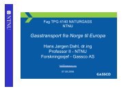
DESIGN AV GASSTRANSPORTSYSTEMER<br />
16. september 2004<br />
TPG4140 – NATURGASS<br />
<strong>NTNU</strong><br />
Morten Aamodt<br />
Fagleder system design<br />
STATOIL ASA<br />
morm@statoil.com<br />
1
Gasstransport<br />
� Innhold<br />
� Del 1:<br />
� Innledning<br />
� Gasstransport norsk sokkel<br />
� Maksimal utnyttelse av gass infrastrukturen<br />
� Del 2:<br />
� System design av rørledninger<br />
� Utbygging av nye gassfelt<br />
� Kristin<br />
� Ormen Lange/Langeled<br />
� Økt utnyttelse<br />
� Åsgard Transport<br />
TPG4140 – NATURGASS<br />
<strong>NTNU</strong><br />
2
Discovered Remaining Undeveloped Discovered Remaining Undeveloped gas: gas: gas: 6954 8763 6954 8763 1713 TCF<br />
TCF<br />
TCF<br />
3
Norwegian Pipeline System<br />
� Technical services are provided by Statoil<br />
for the world's most extensive submarine<br />
gas pipeline system, which runs from<br />
Norway and its offshore fields to continental<br />
Europe.<br />
� 6000 km pipelines (30” – 42”)<br />
� Transport capacity approx. 270 MSm3/d<br />
� Statoil is a leader in the construction of<br />
large-diameter pipelines in deep water. The<br />
group has developed extensive expertise in<br />
pipeline technology and the operation of<br />
advanced pipeline systems.<br />
� On 1 st January 2002, Gassco became the<br />
operator for most of the gas pipeline<br />
systems from the Norwegian continental<br />
shelf.<br />
� On 1 st January 2003, GasLed became the<br />
owner for most of the gas pipeline systems<br />
(Statoil share 20.38%).<br />
4
Norwegian Pipeline System<br />
Gas pipeline<br />
system<br />
Size each<br />
leg, inch<br />
Length<br />
km<br />
Depth<br />
m<br />
Statpipe<br />
Oper.<br />
Year<br />
1985 28, 30, 36, 36 880 300<br />
Zeepipe 1993 30, 40 850 80<br />
Europipe 1995 40 670 70<br />
Troll gas 1996 36, 36 130 360<br />
Zeepipe II 1996 40, 40 610 370<br />
Haltenpipe 1996 16 250 360<br />
Franpipe 1998 42 840 70<br />
Europipe II 1999 42 660 300<br />
Åsgard Transp 2000 42 700 370<br />
Heidrun/Norne 2001 16 200 350<br />
5
Transport capacity in gas pipelines<br />
Terms and conditions<br />
� Hydraulic Capacity (Hyd)<br />
The maximum volume of natural gas physically possible to transport through the pipeline<br />
under given conditions<br />
� Available Technical Capacity (ATC)<br />
The capacity may be limited by a system boundary condition, e.g. lack of export<br />
compression to fill the pipeline. The ATC is the actual capacity available for a given period<br />
� Committable Capacity (Com)<br />
The committable capacity takes into account both the fuel consumption and an operational<br />
flexibility factor. The relation between the ATC and the Com is given by:<br />
� Bookable capacity<br />
This capacity defines the maximum allowed booking level. The capacity equals the Com<br />
minus the retained capacity as defined in the Booking Manual<br />
� Booked Capacity<br />
The sum of the converted bookings as of 31.12.02 and later bookings as recorded on<br />
Gasviagasled.com<br />
Q<br />
COM<br />
=<br />
( 1<br />
Q<br />
ATC<br />
Opflex<br />
+ Fuel ) * ( 1+<br />
)<br />
100 100<br />
6
Kollsnes<br />
7
Kollsnes som blandebatteri<br />
Bruker Troll gass for blande ut<br />
CO2 rik Kvitebjørn gass for å være<br />
innenfor salgsgass spesifikasjon<br />
på 2.5 mol% CO2<br />
Felt CO2<br />
Troll A 0.30<br />
Troll B&C 1.00<br />
Kvitebjørn 3.80<br />
Visund 1.25<br />
From DPC 0<br />
0.77 % CO2<br />
Pipeline<br />
Compressor “A”<br />
0 MSm³/sd<br />
Kollsnes - Sleipner<br />
21 MSm³/sd<br />
157.12 bara pipeline inlet pressure<br />
Train No. 1<br />
1.13 % CO2<br />
0.0 MSm³/sd<br />
Pipeline<br />
0.8 % CO2 0.77 % CO2 Compressor “B”<br />
0 MSm³/sd Comp<br />
A<br />
ZpIIA ZpIIB<br />
1 0<br />
Pipeline<br />
B<br />
C<br />
0<br />
1<br />
1<br />
0<br />
0 0.77 % CO2 Compressor “C”<br />
0 MSm³/sd D 0 1<br />
From DPC<br />
E 1 0<br />
Train No. 2<br />
0.0 MSm³/sd<br />
0.8 % CO2 1.13 % CO2<br />
Pipeline<br />
Compressor “D”<br />
21 MSm³/sd<br />
F 0<br />
1: Deliver<br />
0: Closed<br />
1<br />
From DPC<br />
Train No. 3<br />
1 1.13 % CO2<br />
Pipeline<br />
Compressor “E”<br />
21 MSm³/sd<br />
0 MSm³/sd<br />
2.45 % CO2<br />
Each compressor deliver to<br />
only one pipeline<br />
37.0 MSm³/sd 173.01 bara pipeline inlet pressure<br />
0.8 % CO2 Future Pipeline<br />
41 MSm³/sd<br />
1<br />
3.84 % CO2 Compressor “F”<br />
20 MSm³/sd<br />
Kollsnes - Draupner<br />
From new NGL<br />
extraction train<br />
Total 62 MSm³/sd<br />
25.0 MSm³/sd 78 bara<br />
3.84 % CO2 1: Running<br />
0: Down<br />
8
Sleipner – knutepunkt for norsk gass<br />
�Fleksibilitet til å nå ulike marked<br />
(leveransepunkter)<br />
�Blandetjenester (gasskvalitet)<br />
�Økt regularitet<br />
9
Terminalen i Dunkerque<br />
PIG TRAP<br />
3 PROSESS TOG FOR TRYKK<br />
OG TEMPERATUR KONTROLL<br />
FISCAL MÅLESTASJON<br />
FYRKJEL FOR<br />
OPPVARMING AV GASS<br />
PIG TRAP<br />
GAS DE FRANCE<br />
10
Reservoar<br />
betingelser<br />
Økt utnyttelse av gassrørledningene –<br />
en oversikt !<br />
Rørledningsdesign<br />
Nye design normer<br />
Trykksprang<br />
Optimalisering av system og drift<br />
Redusert operasjonell fleksibilitet<br />
Kapasitetstester<br />
Reduserte operasjonelle marginer<br />
Teknologi utvikling: Flytforbedrer<br />
Forsterkningsløsninger<br />
Markedsbetingelser<br />
Økt utnyttelsesgrad av stålet i rørveggene<br />
Bruke høyere andel av hydraulisk kapasitet<br />
Reell kapasitet/reduserer usikkerhet<br />
Marginer nødvendig for å oppnå høy<br />
regularitet<br />
Utvikling av flytforbedrer for rikgass<br />
ledninger pågår<br />
Midtveis kompresjon og parallelle rør<br />
11
Kapasitetstest gir kunnskap om reell<br />
kapasitet<br />
Forutsetninger for en vellykket test:<br />
�Test avhengig av stabile forhold (volum trykk, temperatur)<br />
�Test bør gjøres med så høy rate som mulig<br />
�Nøyaktig instrumentering (kalibrering)<br />
Kapasitet MSm³/d<br />
p ut1<br />
∆p<br />
q 1<br />
p inn1<br />
p test<br />
q 2<br />
p inn2<br />
Etter kapasitetstest<br />
Design<br />
p<br />
Tunings parametere:<br />
�friksjonsfaktor (ruhet)<br />
�varmeovergang<br />
12
Increased pipeline capacity<br />
Zeepipe IIA<br />
Zeepipe IIB<br />
Europipe II<br />
Europipe<br />
Franpipe<br />
Zeepipe I<br />
Statpipe<br />
Statpipe RG<br />
<strong>ÅT</strong><br />
0 10 20 30 40 50 60 70 80 90<br />
Design Today Upgraded potential<br />
13
Utnyttelse av stålet i rørledninger på land<br />
og i sjøen<br />
� Rørledninger skal tradisjonelt ha samme designtrykk langs hele lengden<br />
� Designsituasjonen for gassrør er en pakket ledning mot stengt nedstrømsventil<br />
� Lange landrørledninger har relativt lavt designtrykk og mange<br />
kompressorstasjoner<br />
� Kompresjon på land er relativt billig, begrenset trykkfall mellom stasjoner<br />
� God gjennomsnittlig utnyttelse av stålet i røret som trykkbeholder<br />
� Lange sjørørledninger har høyt designtrykk, men ikke kompresjon<br />
underveis<br />
� Utvendig overtrykk krever økt veggtykkelse som kan utnyttes for innvendig trykk<br />
� Kompresjon gjøres oppstrøms, stort trykkfall til nedstrøms ende<br />
� Ikke så god gjennomsnittlig utnyttelse av stålet i røret som trykkbeholder<br />
p d<br />
Landrør<br />
Trykkfallskurve<br />
Lavere utnyttet rørmateriale<br />
p d<br />
Sjørør<br />
Trykkfallskurve<br />
Lavere utnyttet rørmateriale<br />
Oppstrøms ende Nedstrøms ende Oppstrøms ende Nedstrøms ende<br />
14
Dimensjoneringskriterier<br />
� Forenklet kan man si at veggtykkelsen til en undervanns rørledning dimensjoneres<br />
for:<br />
� maksimum innvendig driftstrykk (driftsfasen)<br />
� ytre vanntrykk (installasjonsfasen, tomt rør)<br />
� I seksjoner der det ytre vanntrykket er dimensjonerende, vil veggtykkelsen i røret<br />
være større enn det som er nødvendig for røret som en trykkbærende beholder,<br />
noe som bør utnyttes til å øke innvendig trykk i røret dersom dette er praktisk<br />
mulig.<br />
Nødvendig veggtykkelse<br />
(mm)<br />
35<br />
30<br />
25<br />
20<br />
15<br />
10<br />
5<br />
0<br />
0 200 400 600 800<br />
Vanndybde (m)<br />
Potensial for økt kt indre trykk<br />
Veggtykkelse for<br />
gitt innvendig<br />
designtrykk<br />
Kollaps<br />
p.g.a.utvendig<br />
overtrykk<br />
15
Høyere utnyttelse av røret som<br />
trykkbeholder<br />
� Kan stålet i rørveggen utnyttes bedre?<br />
� Avanserte verktøy for tilstandsovervåkning under<br />
drift<br />
� God skadestatistikk, overtrykk er ikke skadeårsak<br />
� Bedre stål egenskaper og toleransekontroll ved<br />
fremstilling av rørene<br />
� Bedre sveise og testprosedyrer<br />
� Er det nødvendig at en lang gassrørledning skal tåle<br />
samme trykk nedstrøms som oppstrøms?<br />
� Under vanlig drift er trykkfallet betydelig over<br />
lengden av rørledningene<br />
� Nedstrøms enden ser sjelden eller aldri maksimalt<br />
driftstrykk<br />
� Men designstandarder og industripraksis forutsetter<br />
overtrykksbeskyttelse på det stedet der<br />
designtrykket endres<br />
Utvendig diameter De<br />
Innvendig diameter Di<br />
Di < De<br />
16
Trykksprangkonsept - prinsipp<br />
� To eller flere nivåer for designtrykk langs rørledningen<br />
� Ingen lokal overtrykksbeskyttelse der designtrykket reduseres<br />
� Trykk-kontroll og overtrykksbeskyttelse baseres på overføring av driftsdata fra nedstrøms<br />
enden til oppstrøms enden ved hjelp av høypålitelig kommunikasjon<br />
� Sentrale forutsetninger<br />
pd<br />
� Trykkfallskurven skal under normal drift alltid ligge under designtrykk-kurven<br />
� Utjevningstrykket skal under normal drift ikke kunne overstige laveste designtrykk<br />
� Utjevningstrykket skal under unormale driftssituasjoner ikke kunne overstige laveste<br />
maksimum tillatt tilfeldig trykk "maximum incidental pressure” (MIP)<br />
Konstant designtrykk<br />
pd1<br />
To designtrykknivåer<br />
Utjevningstrykk<br />
Trykkfallskurve Trykkfallskurve<br />
Lavere utnyttet rørmateriale Lavere utnyttet rørmateriale<br />
Oppstrøms ende Nedstrøms ende Oppstrøms ende Nedstrøms ende<br />
pd2<br />
17
Trykksprangkonseptet - anvendelser<br />
� Zeepipe IIA (implementert)<br />
� Oppstrøms design trykk økt fra 172 til 191 barg<br />
p.g.a. høyt utvendig trykk på dypt vann<br />
� Kapasiteten økt med 40%<br />
� Europipe II (implementert)<br />
� Landfall forberedt med design trykk 163.4 barg (tunnel<br />
Europipe I)<br />
� Oppstrøms design trykk designet for 191 barg<br />
� Kapasitet økt med 22%<br />
� Forlengelse av Åsgard Transport til Norne/Heidrun<br />
(ikke implementert)<br />
� Åsgard Transport har design trykk 212 barg<br />
� Norne-Heidrun rørledningen har design trykk 280 barg<br />
� Kapasiteten i Åsgard Transport kan opprettholdes<br />
� Oppgradering av Zeepipe IIA/B (godkjent av<br />
myndigheter)<br />
� Basert på DNV OS-F101<br />
� Oppstrøms design trykk økes til<br />
� Zeepipe IIA; 200.3 barg<br />
� Zeepipe IIB: 205.2 barg<br />
� Tre design trykk nivåer for begge rørledningene<br />
� 24% økt totalkapasitet ut fra Kollsnes<br />
191 barg<br />
163 barg<br />
280 barg<br />
212 barg<br />
191 barg<br />
172 barg<br />
Norne<br />
Zeepipe IIA<br />
Kollsnes KP 135 Sleipner<br />
Europipe 2<br />
<strong>Kå</strong>rstø KP 350 Dornum<br />
Åsgard transport<br />
Åsgard Kallstø<br />
18
Technology drivers<br />
Natural gas<br />
Snøhvit +<br />
Western<br />
Africa<br />
NCS gas<br />
Snøhvit<br />
LNG<br />
Expand NCS business:<br />
Expand NCS business:<br />
• Increase capacity of current pipelines<br />
• Increase capacity of current pipelines<br />
• Tie-in of new infrastructure<br />
• Tie-in of new infrastructure<br />
• Extraction of NGL (<strong>Kå</strong>rstø)<br />
• Extraction of NGL (<strong>Kå</strong>rstø)<br />
• CO2 and N2 emissions from processing<br />
• CO2 and N2 emissions from processing<br />
• LNG production (Snøhvit)<br />
• LNG production (Snøhvit)<br />
• Mega-scale methanol production<br />
• Mega-scale methanol production<br />
• Power or combined heat and power production from<br />
• Power or combined heat and power production from<br />
gas (<strong>Kå</strong>rstø, Kollsnes, Skogn, others)<br />
gas (<strong>Kå</strong>rstø, Kollsnes, Skogn, others)<br />
The<br />
Caspian<br />
New<br />
New<br />
business<br />
business<br />
opportunities:<br />
opportunities:<br />
•<br />
•<br />
Mega-scale<br />
Mega-scale<br />
GTL<br />
GTL<br />
plants<br />
plants<br />
(Iran)<br />
(Iran)<br />
•<br />
•<br />
Floating<br />
Floating<br />
LNG<br />
LNG<br />
production<br />
production<br />
(Nnwa)<br />
(Nnwa)<br />
•<br />
•<br />
Deep<br />
Deep<br />
water<br />
water<br />
pipelines?<br />
pipelines?<br />
•<br />
•<br />
Onshore<br />
Onshore<br />
pipelines?<br />
pipelines?<br />
19
Gasstransport<br />
Del 2<br />
� System design av rørledninger<br />
� Utbygging av nye gassfelt<br />
� Kristin<br />
� Snøhvit<br />
� Økt utnytting<br />
� Åsgard Transport<br />
20
Pipeline System Design<br />
Work process<br />
Thermohydraulic<br />
analysis<br />
Internal diameter,<br />
capacity, pressure<br />
and temperature<br />
profile, etc.<br />
Functional<br />
requirements;<br />
gas routing,<br />
regularity,<br />
gas quality,<br />
agreements<br />
Functional<br />
requirements,<br />
Regularity,<br />
Deliverability<br />
Overall<br />
Operational<br />
Philosophy;<br />
Control and Safety<br />
System,<br />
Environment, etc.<br />
Control and Safety<br />
Philosophy<br />
Boundary conditions and technical interface between platform – pipeline – terminal<br />
QA<br />
System design<br />
concept<br />
Pipeline System<br />
Diagram, Process<br />
Flow Diagram<br />
P&ID’s<br />
21
Pipeline System Design<br />
System definition<br />
� The extent of the pipeline system, its functional requirements and applicable<br />
legislation should be defined and documented.<br />
� The extent of the system should be defined by describing the system,<br />
including the facilities with their general locations and demarcations and<br />
interfaces with other facilities.<br />
� The functional requirements should define the required design life and design<br />
conditions. Foreseeable normal, extreme and shut-in operating conditions with<br />
their possible ranges in flowrates, pressures, temperatures, fluid compositions<br />
and fluid qualities should be identified and considered when defining the<br />
design conditions.<br />
� Terms and definitions<br />
Petroleum and natural gas industries<br />
Pipeline transportation systems, ISO 13623<br />
OS F-101: Submarine Pipeline Systems<br />
22
Pipeline System Design<br />
Terms and definitions<br />
� Pipeline system<br />
� A pipeline with compressors or pump stations<br />
� Pressure reduction stations<br />
� Metering<br />
� Tankage<br />
� Supervisory control and data acquisition system (SCADA)<br />
� Safety systems<br />
� Corrosion protection systems<br />
� And other equipment, facility or building used in the transportation of fluids<br />
� Pipeline<br />
� Those facilities through which fluids are conveyed, including pipe, pig traps,<br />
components and appurtenances, up to and including the isolation valve.<br />
Petroleum and natural gas industries<br />
Pipeline transportation systems, ISO 13623<br />
23
Pipeline System Design<br />
Design premises<br />
� Pipeline Route<br />
� Length<br />
� Bathymetric profile<br />
� Environmental Conditions<br />
� Air temperature<br />
� Sea bottom temperature<br />
� Ground temperature<br />
� Geo-technical data (soil conditions)<br />
� Pipeline Data<br />
� Design pressure<br />
� Design temperature<br />
� Internal diameter<br />
� Wall thickness<br />
� Internal coating<br />
� Concrete coating<br />
� Insulation<br />
� Trenching/dredging<br />
� Gravel/rock dumping<br />
� Gas composition<br />
� Gas properties<br />
� Equation of state<br />
� Friction equation<br />
� Internal roughness<br />
� Transport specification<br />
� Sales gas specifications<br />
� Pressure Control System<br />
� Pressure regulating<br />
� Pressure safety<br />
� Pig trap arrangement<br />
� Pigging philosophy<br />
� Pipeline valve philosophy<br />
� Future requirements<br />
24
Pipeline System Design<br />
Gas value chain<br />
� The objective of the system design is to develop overall transport solutions for<br />
the gas chain from the field to the market which will maximize the value of the<br />
liquid- and gas products and without any unreasonable external conditions for<br />
any third party (fields or transport systems).<br />
� The main objective in design and operation of gas pipeline systems is to<br />
deliver gas quantities nominated by the buyers within the desired quality<br />
specifications. Within reasonable technical and economical limits and relevant<br />
agreements, necessary means to ensure high availability and regularity will be<br />
used.<br />
25
Pipeline System Design<br />
Hydraulic analysis<br />
� The hydraulic design of a pipeline system is part of the conceptual<br />
development of a gas pipeline <strong>project</strong>.<br />
� The hydraulics of the pipeline system should be analysed to demonstrate that<br />
the system can safely transport the fluids for the design conditions specified<br />
by the system definition, and to identify and determine the constraints and<br />
requirements for its operation. This analysis should cover steady-state and<br />
transient operating conditions.<br />
� The hydraulic design is an optimisation process of several system parameters:<br />
� Boundary conditions both at upstream and downstream end<br />
� pressure and temperature<br />
� Physical transport properties; gas composition<br />
� Design gas flowrate<br />
� Internal wall roughness<br />
� Environmental conditions; ambient temperature, overall heat transfer coefficient<br />
26
Pipeline System Design<br />
Hydraulic analysis<br />
� Predict the pipeline capacity and minimize the uncertainty<br />
� Describe the function loads for the pipeline design<br />
� Pressure profile<br />
� Temperature profile<br />
� Density profile (fluid)<br />
� Velocity profile<br />
� Design cases:<br />
� Normal operation, start-up, planned shut-down, etc.<br />
� Not planned operation, emergency shut-down, depressurisation, etc.<br />
� Emergency preparedness analysis; accidents, pipe rupture, leakage etc.<br />
27
Pressure, barg<br />
240<br />
220<br />
200<br />
180<br />
160<br />
140<br />
120<br />
100<br />
Ormen Lange Transport<br />
Pipeline capacity<br />
Ormen Lange - Gass ekport fra Nyhamn via Sleipner til Easington (UK)<br />
Nyhamn exp. press. - Sleipner@151barg Sleipner exp. pressure 42" Sleipner exp. pressure 44"<br />
Sleipner exp. pressure 46" Sleipner exp. pressure 48" Sleipner press. - Nyhamn@248 barg<br />
Sleipner press. - Nyhamn@213 barg Sleipner @149 barg<br />
Easington 73 barg<br />
10.0 20.0 30.0 40.0 50.0 60.0 70.0 80.0 90.0 100.0 110.0<br />
Hydraulic capacity, MSm3/d<br />
42"<br />
Sleipner pressure<br />
varying<br />
42" 42"<br />
42" 44"<br />
46"<br />
48"<br />
28
System design<br />
Flow control<br />
� A single pipeline network system is normally operated on flow control. At the<br />
upstream end(s) the producing fields or other facilities are often aiming to<br />
introduce the gas at a steady state. At the downstream end the gas off-take<br />
may also be at flow control. The pressure in the system is therefore dependent<br />
on the inventory (packing condition) in the pipeline. If the input to the system<br />
is less than the output, the system would be de-packed, and the system<br />
pressure would decrease. By doing this, the system could be operated both in<br />
packed and de-packed condition, depending on the status of the system.<br />
29
System design<br />
Pressure control<br />
� Because a pipeline system is normally operated on flow control, the pressure<br />
control system is installed to protect the system against overpressurisation<br />
(design and maximum incidental pressure). The pressure control system may<br />
also be used in combination with the flow control system to ensure that the<br />
pressure is kept above a specified minimum pressure either by contractual or<br />
technical matters.<br />
30
System design<br />
Temperature control<br />
� The temperature control system is required to protect the pipeline system<br />
against temperatures above or below the specified design temperatures. The<br />
maximum design temperature may be reached at the compressor outlet due to<br />
the pressure increase. The minimum design temperature may be reached due<br />
to expansion of the gas through the pipeline, valves, etc.<br />
Pressure, barg<br />
160<br />
140<br />
120<br />
100<br />
80<br />
60<br />
40<br />
20<br />
0<br />
Sleipner - Easington pipeline, future Sleipner compression<br />
68M barg 58M barg 48M barg 38M barg 68M Deg C<br />
58M Deg C 48M Deg C 38M Deg C<br />
0 100 200 300 400 500<br />
km from Sleipner<br />
80<br />
70<br />
60<br />
50<br />
40<br />
30<br />
20<br />
10<br />
0<br />
Temperature, °C<br />
31
System design<br />
Metering<br />
� The gas will be fiscally metered both at the gas inlet and outlet locations. The<br />
main purpose of the metering system is for tariffs and allocations purposes.<br />
The system will also be a part of the leak detection system<br />
32
System design<br />
Compression and cooling<br />
� At the compressor outlet, the temperature may be too high to allow the gas<br />
into the pipeline. The gas is therefore cooled to a temperature below the<br />
maximum design temperature. The need for a cooling unit downstream the<br />
compressor is normally determined by the compressor pressure ratio.<br />
33
System design<br />
Heating<br />
� During operation of the pipeline system<br />
the minimum design temperature may be<br />
violated due to high utilisation of the<br />
system or high pressure gradients in parts<br />
of the system (Joule-Thomson effect).<br />
During normal operation heating of the<br />
gas may be required to avoid the<br />
temperature to drop below the minimum<br />
design temperature or other limitations<br />
(sales agreements). In upset situations the<br />
pressure build-up in parts of the system<br />
may cause the temperature to drop below<br />
the minimum design temperature. Heating<br />
of the gas may therefore be required in<br />
order to avoid the minimum temperature<br />
to be violated.<br />
34
System design<br />
Gas Quality<br />
� To avoid deposits in a pipeline and to minimise the possibility of any kind of<br />
corrosion, including internal stress corrosion, it is essential that the gas<br />
should conform to the following:<br />
� The water dew-point, at the working pressure, should at all times be below the<br />
temperatures of the pipeline.<br />
� The hydrocarbon dew-point, at the working pressure, should at all times be<br />
below the temperature of the pipeline – this will also ensure that the calorific<br />
value of the gas is not reduced by condensation of hydrocarbons.<br />
� It should be dust-free.<br />
35
Kristin<br />
36
S<br />
R<br />
P<br />
FORE<br />
Template and<br />
well slot ID’s:<br />
AFT<br />
S3 S4<br />
STB PORT<br />
S2 S1<br />
R-103/R-201<br />
FORE<br />
FORE<br />
N-102/N-201<br />
N<br />
S-103/S-201<br />
S-101<br />
S-102<br />
R-101<br />
R-102<br />
P-102/P-201<br />
P-101<br />
Kristin - Subsea & export field layout<br />
N-101<br />
Kristin<br />
Semi<br />
Grid North<br />
P-212 N<br />
P-212 S<br />
18” check<br />
valve with<br />
1” by pass<br />
10" ID prod (13% Cr.) w/ DEH<br />
12" oil export (CS)<br />
18" gas export (CS)<br />
Umbilical w/ 2" ID centre line<br />
3.5“ ID service line (CS)<br />
Fibre optical cable (FOC)<br />
Direct el. heating (DEH) risers<br />
Future tie-in hub<br />
SSIV<br />
ROV operated ball valve<br />
Check valve<br />
Diverless hot tap tee<br />
Temporary pig launcher<br />
P-211 P-211 Oil Oil export export<br />
Fibre Fibre optical optical cable cable<br />
Pig Pig direction direction<br />
P-212 Gas export loop<br />
Completed well<br />
Completion ongoing<br />
Drilled and capped well<br />
Drilling commenced<br />
Planned well<br />
Spare well slot<br />
Åsgard C<br />
To Åsgard<br />
FOC-1/B-401<br />
Åsgard Åsgard Transport Transport P-121 P-121<br />
Size Length Installed<br />
Tag [mm ID] [Km] Date<br />
Flowlines:<br />
N-101 254.0 6.0<br />
P-101 254.0 6.8<br />
S-101 254.0 6.0<br />
S-102 254.0 6.1<br />
R-101 254.0 6.7<br />
R-102 254.0 6.7<br />
Total flowline 38.3<br />
* excl. riser lengths (640-670 m)<br />
Service lines:<br />
N-102 90.6 2.6<br />
P-102 90.6* 6.4<br />
S-103 90.6* 5.7<br />
R-103 90.6 2.0<br />
Total service line 16.7<br />
*89.2 in zone 2<br />
Umbilicals:<br />
N-201 2.6<br />
P-201 6.4<br />
S-201 5.7<br />
R-201 2.0<br />
Total umbilical 16.7<br />
Export pipelines:<br />
P-211 294.8 22.7<br />
P-212 411.2 30.0<br />
Fibre optical cable:<br />
FOC 26.4<br />
Structures:<br />
Template N 23.07.03<br />
Template P 27.07.03<br />
16” check<br />
Template S 09.05.03<br />
valve with<br />
1” by pass<br />
(ROV op)<br />
16”<br />
Kristin<br />
Tee<br />
Template R<br />
Manifold N<br />
Manifold P<br />
Manifold S<br />
Manifold R<br />
FRB N-101<br />
FRB P-101<br />
FRB S-101<br />
FRB S-102<br />
FRB R-101<br />
FRB R-102<br />
ERB P-212N<br />
ERB P-212S<br />
26.07.03<br />
Template Heading Depth As installed centre positions<br />
Grid UTM Zone 32 Central Median 9 o E<br />
N 199.6 o<br />
368 m E 381 290.05m N 7 214 135.25m<br />
P 200.6 o<br />
372 m E 379 280.50m N 7 212 712.38m<br />
S 181.1 o<br />
364 m E 378 957.28m N 7 208 585.34m<br />
R 180.3 o<br />
Structures:<br />
Template N 23.07.03<br />
Template P 27.07.03<br />
16” check<br />
Template S 09.05.03<br />
valve with<br />
1” by pass<br />
(ROV op)<br />
16”<br />
Kristin<br />
Tee<br />
Template R<br />
Manifold N<br />
Manifold P<br />
Manifold S<br />
Manifold R<br />
FRB N-101<br />
FRB P-101<br />
FRB S-101<br />
FRB S-102<br />
FRB R-101<br />
FRB R-102<br />
ERB P-212N<br />
ERB P-212S<br />
26.07.03<br />
Template Heading Depth As installed centre positions<br />
Grid UTM Zone 32 Central Median 9<br />
356 m E 379 050.74m N 7 206 650.42m<br />
o E<br />
N 199.6 o<br />
368 m E 381 290.05m N 7 214 135.25m<br />
P 200.6 o<br />
372 m E 379 280.50m N 7 212 712.38m<br />
S 181.1 o<br />
364 m E 378 957.28m N 7 208 585.34m<br />
R 180.3 o<br />
356 m E 379 050.74m N 7 206 650.42m<br />
Statoil Kristin Subsea & Export: Schematic field layout<br />
37<br />
Drw. No: C074-ZAA-U-XE-0001-04 Date: 180803
Kristin<br />
Subsea pressure protection<br />
Subsea PSD System<br />
PRODUCTION<br />
MASTER VALVE<br />
(PMV)<br />
SCSSV<br />
PRODUCTION<br />
WING VALVE<br />
(PWV)<br />
(located topside)<br />
1<br />
CHOKE<br />
PTx2<br />
TO PRODUCTIONMANIFOLD<br />
2<br />
HIPPS control logic<br />
(local)<br />
PT (2x)<br />
PT (2x)<br />
From Manifold Flowline to SSIV<br />
HIPPS<br />
VALVE(S)<br />
SSIV<br />
Riser PSV<br />
3<br />
38
Ormen Lange Concept Screening<br />
� Gas supply<br />
� Production profile<br />
� Build-up and plateau<br />
� Market scenarios<br />
� Volume<br />
� Market opportunities<br />
� Company based sales<br />
� Existing infrastructure<br />
� Platforms<br />
� Tie-ins and functional requirements<br />
� Pipelines<br />
� Capacity and ullage<br />
� New infrastructure<br />
39
Ormen Lange Transport<br />
Nyhamna - Easington<br />
U.K.<br />
Easington<br />
KP 537<br />
! ! ! !<br />
! ! ! !<br />
!<br />
*<br />
*<br />
! ! ! !<br />
!<br />
!<br />
! !<br />
!<br />
! !<br />
! !<br />
! !<br />
!!<br />
*<br />
*<br />
! !<br />
**<br />
KP KP 100 100<br />
!<br />
!<br />
! !<br />
KP 150<br />
KP KP 200 200<br />
KP KP 250 250<br />
KP KP 300 300<br />
KP KP 350 350<br />
KP KP 400 400<br />
KP KP 450 450<br />
KP KP 500 500<br />
KP KP 550 550<br />
Sleipner<br />
KP 0<br />
KP KP 625 625<br />
KP 50<br />
KP 100<br />
KP 150<br />
KP 200<br />
KP 250<br />
KP 300<br />
KP 350<br />
Sleipner - Easington 42", 537 km<br />
KP 400<br />
KP 450<br />
Nyhamna - Sleipner 42", 625 km<br />
*<br />
!<br />
!<br />
!<br />
! !<br />
*<br />
!<br />
! !<br />
!<br />
!<br />
! ! ! !! ! ! ! ! !<br />
! !<br />
!<br />
! !<br />
* *<br />
* *<br />
!<br />
!<br />
!<br />
!<br />
! !<br />
!!<br />
!<br />
! !<br />
*<br />
! !! !<br />
Ormen Lange - Nyhamna 2 x 30", 90 km<br />
ORMEN LANGE<br />
Nyhamna<br />
KP 0<br />
KP 150<br />
! !<br />
!<br />
!<br />
KP KP 50 50<br />
! !<br />
! !<br />
!<br />
!<br />
!<br />
! !<br />
*<br />
*<br />
NORWAY<br />
NORWAY<br />
! !<br />
! !<br />
! !<br />
*<br />
*<br />
!<br />
! !<br />
*<br />
! !<br />
!! !<br />
*<br />
*<br />
!<br />
!<br />
*<br />
!<br />
*<br />
*<br />
! !<br />
*<br />
!<br />
! !<br />
!<br />
!!<br />
DENMARK<br />
*<br />
! !<br />
*<br />
*<br />
! *<br />
* *<br />
*<br />
*<br />
*<br />
!<br />
*<br />
*<br />
*<br />
!<br />
*<br />
*<br />
� Largest pipeline <strong>project</strong> on the Norwegian<br />
Continental Shelf<br />
� The new pipeline will be 1166 km long<br />
� Large volumes and fast build up profiles<br />
give an efficient and flexible transportation<br />
solution<br />
� Northern leg<br />
� 42” pipeline with design pressure 215/250<br />
barg<br />
� Capacity of 70 – 80 MSm3/d of gas<br />
� Tie-in to Sleipner Riser plt.<br />
� Southern leg<br />
� 44” pipeline with design pressure 156.8<br />
barg<br />
� Capacity of 70 - 74 MSm3/d of gas<br />
40
Ormen Lange Transport<br />
Sleipner<br />
� The Ormen Lange Transport will be an<br />
integrated part of the Norwegian gas<br />
infrastructure system<br />
� The connection to Sleipner Riser plt.<br />
gives flexibility to route gas both to the<br />
Continent and to the UK<br />
� Other gas sources than Ormen Lange<br />
can also supply gas to the UK<br />
41
Sleipner as gas centre<br />
SLA<br />
SLT<br />
Kollsnes – Sleipner<br />
Nyhamna – Sleipner<br />
Sleipner gas<br />
Total<br />
SLR<br />
70 MSm3/d<br />
70 MSm3/d<br />
20 MSm3/d<br />
160 MSm3/d<br />
42
Sleipner Riser Platform<br />
Blending services<br />
WI (MJ/Sm³)<br />
52.0000<br />
51.8000<br />
51.6000<br />
51.4000<br />
51.2000<br />
51.0000<br />
50.8000<br />
Wobbe Index<br />
50.6000<br />
50 60 70 80 90 100<br />
Ormen Lange Gas (%)<br />
OL1-Troll<br />
OL2-Troll<br />
OL1-SL<br />
OL2-SL<br />
max<br />
� One of the main advantages of tying in<br />
Ormen Lange to the Norwegian gas<br />
network is to allow for quality<br />
adjustment. The Ormen Lange Wobbe<br />
Index is rather high, and it may be a<br />
challenge to meet UK specifications<br />
without blending with other gas.<br />
� On the other hand, the Ormen Lange gas<br />
has a low CO2-content, giving the<br />
possibility to dilute other Norwegian gas<br />
to reduce the growing CO2-challenge in<br />
the gas delivery network:<br />
� Sleipner gas<br />
� High CO2<br />
� Troll gas<br />
� Low CO2<br />
� Ormen Lange<br />
� High Wobbe Index<br />
� Low CO2<br />
43
Process Flow Diagram<br />
Sleipner and Ormen Lange Transport<br />
27-KA01A<br />
27-KA01B<br />
26-KA01<br />
Sleipner T<br />
Nyhamna<br />
XV HV<br />
M<br />
M<br />
Injection<br />
XV EV<br />
42"<br />
16"<br />
EV<br />
EV560<br />
20"<br />
EV<br />
6 metering<br />
tubes<br />
SLA Bridge SLR<br />
PV169<br />
16"<br />
EV171<br />
16"<br />
HIPPS<br />
EV172<br />
EV990<br />
20"<br />
20"<br />
EV994<br />
16" 16"<br />
XV HV HV<br />
FV XV<br />
30" 30"<br />
M<br />
M<br />
FV170<br />
FV197<br />
M<br />
XV201<br />
20"<br />
XV200<br />
XV202<br />
FV138 FV137<br />
FV<br />
XV<br />
M<br />
M<br />
XV196 XV195 XV194<br />
12" 24" 24" 24"<br />
M<br />
16"<br />
EV<br />
EV<br />
20"<br />
20"<br />
XV088<br />
XV087 12" HV098 24"<br />
XV113<br />
XV114<br />
24"<br />
XV151 EV156<br />
XV141 12" HV186 30"<br />
44"<br />
HV136<br />
EV094<br />
EV124<br />
M<br />
XV<br />
M<br />
20" 20"<br />
40"<br />
40"<br />
EV085<br />
XV<br />
FV<br />
EV<br />
30"<br />
FV139<br />
20"<br />
EV150<br />
EV180<br />
EV181<br />
EV115<br />
EV182<br />
HV<br />
XV<br />
Easington<br />
Zeepipe I<br />
Zeebrugge<br />
To / from<br />
Draupner<br />
Zeepipe II A<br />
Kollsnes<br />
XV<br />
44
Pressure, barg<br />
Ormen Lange Transport<br />
Seksjoner med forskjellig design trykk<br />
250<br />
206<br />
200<br />
150<br />
100<br />
50<br />
System design OLT bypass operation<br />
DP @ +30MSL MIP @ +30 MSL 65MSm3/d, 206-77 barg 60MSm3/d, 206-105 barg<br />
60MSm3/d, 191-73 barg PRS Nyhamna PRS Easington<br />
0<br />
100<br />
200<br />
Operation and<br />
settle out pressure<br />
must be 2 bar below<br />
design pressure<br />
300<br />
400<br />
500<br />
600<br />
700<br />
km from Nyhamna<br />
800<br />
900<br />
1000<br />
1100<br />
105<br />
45
Pressure, barg<br />
Ormen Lange Transport<br />
Seksjoner med forskjellig design trykk<br />
250<br />
225<br />
206<br />
200<br />
150<br />
100<br />
System design OLT bypass operation - PSS-2<br />
DP @ +30MSL MIP @ +30 MSL PSS-2 225-125 barg SOP PSS-2<br />
PRS Nyhamna PRS Easington PSS-2 Nyhamna PSS-2 Easington<br />
0<br />
100<br />
200<br />
300<br />
400<br />
500<br />
600<br />
700<br />
km from Nyhamna<br />
800<br />
900<br />
1000<br />
1100<br />
125<br />
105<br />
46
Water depth (m)<br />
-50<br />
-100<br />
-150<br />
-200<br />
-250<br />
-300<br />
-350<br />
-400<br />
<strong>ÅT</strong>/<strong>Kå</strong> <strong>project</strong> – Increased capacity by<br />
Åsgard Transport Looping<br />
0<br />
ERB<br />
KP5.9<br />
Tee locations:<br />
Åsgard: KP7.211<br />
Norne/Heidrun: KP8.406<br />
Kristin: KP21.651<br />
Draugen Tee<br />
KP105.454<br />
Møre Tee<br />
KP180.326<br />
Diver-assisted<br />
Retrofit Hot Tap Tee<br />
KP258<br />
Vøring Tee<br />
KP350.157<br />
Diver-less<br />
Retrofit Hot Tap Tee<br />
KP430<br />
Florø Tee<br />
KP445.105<br />
Kollsnes Tee<br />
KP535.035<br />
Kalstø<br />
(pull in-head)<br />
KP690.0<br />
0 100 200 300 400 500 600 700<br />
Distance KP (km)<br />
47
Åsgard Transport sea bottom temperature<br />
Temperature (°C)<br />
10.5<br />
10.0<br />
9.5<br />
9.0<br />
8.5<br />
8.0<br />
7.5<br />
7.0<br />
6.5<br />
6.0<br />
Åsgard Transport sea bottom temperature<br />
Max temperature (92.5 percentile)<br />
January<br />
February<br />
Åsgard Transport sea March bottom temperature<br />
0 100<br />
9.5<br />
9.0<br />
8.5<br />
8.0<br />
7.5<br />
200 300 400 500<br />
7.0<br />
Distance KP (km)<br />
6.5<br />
6.0<br />
0 100<br />
600<br />
200<br />
Mean temperature April<br />
January<br />
May<br />
February<br />
June<br />
March<br />
July<br />
April<br />
August<br />
May<br />
September<br />
June<br />
October<br />
700<br />
July<br />
November<br />
August<br />
December<br />
Åsgard Transport sea September bottom temperature<br />
Min temperature October (7.5 percentile)<br />
300 400 500 600 700<br />
Distance KP<br />
9.0<br />
(km)<br />
8.5<br />
8.0<br />
7.5<br />
7.0<br />
6.5<br />
6.0<br />
5.5<br />
November<br />
December<br />
0 100 200 300 400 500 600 700<br />
Distance KP (km)<br />
Temperature (°C)<br />
Temperature (°C)<br />
January<br />
February<br />
March<br />
April<br />
May<br />
June<br />
July<br />
August<br />
September<br />
October<br />
November<br />
December<br />
48
<strong>ÅT</strong>/<strong>Kå</strong> <strong>project</strong><br />
Åsgard Transport 42” Looping<br />
Pressure (barg)<br />
220<br />
210<br />
200<br />
190<br />
180<br />
170<br />
160<br />
150<br />
140<br />
130<br />
120<br />
Åsgard Transport 42" looping - 80 MSm³/d<br />
Northern kp7.2 - kp258 / Southern kp430 - kp691<br />
Pressure southern Pressure northern<br />
Temperature southern Temperature northern<br />
0 200 400 600 800<br />
Distance KP (km)<br />
50<br />
45<br />
40<br />
35<br />
30<br />
25<br />
20<br />
15<br />
10<br />
5<br />
0<br />
Temperature (°C)<br />
Pressure (barg)<br />
220<br />
210<br />
200<br />
190<br />
180<br />
170<br />
160<br />
150<br />
140<br />
130<br />
120<br />
Åsgard Transport shut-in pressure<br />
0 4 8 12 16 20 24<br />
Time (hr)<br />
Northern<br />
Northern<br />
Southern<br />
Southern<br />
As is<br />
As is<br />
49
<strong>ÅT</strong>/<strong>Kå</strong> <strong>project</strong><br />
Åsgard Transport 42” Nothern Looping<br />
50
1 2<br />
3<br />
5<br />
4<br />
6<br />
Typical<br />
Hot Tap<br />
Sequence<br />
51
Pressure (barg)<br />
<strong>ÅT</strong>/<strong>Kå</strong> <strong>project</strong> – Increased capacity by<br />
Booster Compressor Kalstø<br />
Åsgard Transport (69.4 vs. 76.9 MSm³/d)<br />
Pressure Booster_press Temperature Booster_temp<br />
210<br />
200<br />
190<br />
180<br />
170<br />
160<br />
150<br />
140<br />
130<br />
120<br />
110<br />
0 200 400 600 800<br />
Distance KP (km)<br />
Booster compressor duty: 15.5 MW (most likely roughness)<br />
50<br />
45<br />
40<br />
35<br />
30<br />
25<br />
20<br />
15<br />
10<br />
5<br />
0<br />
Temperature (°C)<br />
Pressure, barg<br />
140<br />
130<br />
120<br />
110<br />
100<br />
Kalstø Compressor trip<br />
Pressure U/S ESV2001 Pressure D/S ESV2003<br />
Pressure inlet <strong>Kå</strong>rstø Flow <strong>Kå</strong>rstø<br />
0 10 20 30<br />
Time, min<br />
40 50 60<br />
80<br />
70<br />
60<br />
50<br />
40<br />
30<br />
20<br />
10<br />
0<br />
Flow, MSm³/d<br />
52
Pressure, barg<br />
<strong>ÅT</strong>/<strong>Kå</strong> <strong>project</strong> – <strong>Kå</strong>rstø<br />
Roughness and temperature sensitivity<br />
Area B - Åsgard Transport, <strong>Kå</strong>rstø pressure<br />
High Rough Likely Rough Low Rough<br />
130<br />
125<br />
120<br />
115<br />
110<br />
105<br />
100<br />
95<br />
90<br />
85<br />
80<br />
66 68 70 72 74 76 78 80 82 84 86<br />
Hydraulic capacity, MSm³/d<br />
Pressure, barg<br />
104<br />
102<br />
100<br />
98<br />
96<br />
94<br />
92<br />
90<br />
88<br />
<strong>Kå</strong>rstø Pressure<br />
Aug Dec 6°C<br />
Roughness Low<br />
Roughness High<br />
Roughness Likely<br />
Temperature, °C<br />
Temperature, °C<br />
5<br />
3<br />
1<br />
-1<br />
Area B - Åsgard Transport, <strong>Kå</strong>rstø temp.<br />
High Rough Likely Rough Low Rough<br />
-3<br />
66 68 70 72 74 76 78 80 82 84 86<br />
1.4<br />
1.2<br />
1<br />
0.8<br />
0.6<br />
0.4<br />
0.2<br />
0<br />
-0.2<br />
-0.4<br />
-0.6<br />
-0.8<br />
-1<br />
-1.2<br />
-1.4<br />
-1.6<br />
<strong>Kå</strong>rstø Temperature<br />
Aug Dec 6°C<br />
Hydraulic capacity, MSm³/d<br />
Roughness Low<br />
Roughness High<br />
Roughness Likely<br />
53
<strong>ÅT</strong>/<strong>Kå</strong> <strong>project</strong><br />
Pipeline Studio vs. OLGA; P and T profile<br />
Cricondenbar<br />
specification:<br />
105 barg,<br />
i.e. liquid drop out<br />
below that<br />
pressure<br />
Pressure (barg)<br />
112<br />
110<br />
108<br />
106<br />
104<br />
102<br />
100<br />
98<br />
96<br />
94<br />
Åsgard Transport - 80 MSm³/d<br />
Pipeline Studio OLGA Pipeline Studio OLGA<br />
660 665 670 675 680 685 690 695 700 705 710 715<br />
Distance (km - KP)<br />
Onshore<br />
Pres<br />
Temp<br />
4<br />
3<br />
2<br />
1<br />
0<br />
-1<br />
-2<br />
-3<br />
-4<br />
-5<br />
Temperature (°C)<br />
54
Liquid volume flow rate [Sm³/hr]<br />
300<br />
250<br />
200<br />
150<br />
100<br />
50<br />
0<br />
<strong>ÅT</strong>/<strong>Kå</strong> <strong>project</strong><br />
OLGA results Kalstø vs. <strong>Kå</strong>rstø<br />
Liquid flow rate vs. total flow rate<br />
Liquid flow rate <strong>Kå</strong>rstø Liquid flow rate Kalstø<br />
68 70 72 74 76 78 80 82<br />
Total volume flow rate [MSm³/sd]<br />
Liquid content [Sm³]<br />
200<br />
150<br />
100<br />
50<br />
0<br />
Pipeline liquid content vs. total flow rate<br />
Total liquid content <strong>Kå</strong>rstø Total liquid content Kalstø<br />
68 70 72 74 76 78 80 82<br />
Total volume flow rate [MSm³/sd]<br />
55
Statfjord senfase<br />
56
Natural Gas<br />
57