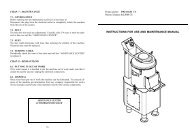
INSTRUCTIONS FOR USE AND MAINTENANCE - mbm-Service ...
INSTRUCTIONS FOR USE AND MAINTENANCE - mbm-Service ...
INSTRUCTIONS FOR USE AND MAINTENANCE - mbm-Service ...

Create successful ePaper yourself
Turn your PDF publications into a flip-book with our unique Google optimized e-Paper software.
4.2.2 Slicer with 3-phase motor<br />
The slicer is equipped with a power supply cord with a section of 5x1mm²and a<br />
length of 1.5m.<br />
Connect the slicer with a 400 Volt - 50 Herz three-phase electric circuit by means<br />
of a CEI plug interposing a differential-magnetothermic switch of 10A., ΔI =<br />
0,03A.. Check that the earthing is fully operational. Before connecting the<br />
machine to the three-phase power supply circuit, check the direction of blade<br />
rotation by pushing the button “I” (ON) (see CHAP. 5.1 FIG. n°8) and<br />
immediately afterwards the cut-off button “0” (OFF).<br />
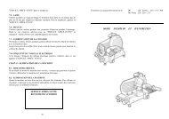
The blade rotation must be anti-clockwise looking at the machine from the blade<br />
guard side (see FIG: n°5).<br />
If the otation is wrong, reverse two of the three power<br />
supply cords in the plug or in the socket (black and grey).<br />
Three-phase motors installed in CE professional slicers<br />
can work with both 230 V.three-phase tension and 400 V<br />
tension.<br />
Unless otherwise specified, connections are made with 400<br />
V. power supply; call the “SERVICE CENTRE” if<br />
matching with the 230 V three-phase circuit. is required.<br />
4.3 - ELECTRIC CIRCUIT DIAGRAMS<br />
4.3.1 - electric circuit diagram of the Normal automatic Single-phase slicer<br />
12<br />
FIG.n°5 - Blade rotation<br />
FIG. n°6 - Electric circuit diagram of Normal automatic Single-phase slicer<br />
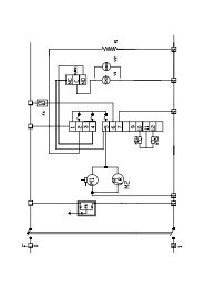
4.3.2 - electric circuit diagram of the Normal automatic Three-phase slicer (see<br />
FIG. n°7)<br />
FIG. n°7 - Electric circuit diagram of normal automatic Three-phase slicer<br />
13