INSTRUCTIONS FOR USE AND MAINTENANCE - mbm-Service ...
INSTRUCTIONS FOR USE AND MAINTENANCE - mbm-Service ...
INSTRUCTIONS FOR USE AND MAINTENANCE - mbm-Service ...

Create successful ePaper yourself
Turn your PDF publications into a flip-book with our unique Google optimized e-Paper software.
over 10 mm respect to the initial diameter. To have it replaced, please call the<br />
“SERVICE CENTRE”.<br />
7.6 - SHARPENING STONES<br />
Check that the sharpening stones keep their abrasion capacity during sharpening:<br />
Otherwise they should be replaced in order not to damage the blade. For<br />
replacement, please call the “SERVICE CENTRE”.<br />
7.7 - LUBRICATING THE SLIDING GUIDES<br />
Occasionally put some oil drops ( from the oil phial supplied with the slicer) on<br />
the round bar on which the carriage slides back and forth, through the hole<br />
located next to the dial knob (OIL).<br />
7.8 - LABEL OF THE PUSH-BUTTON PANEL<br />
If the label of the push-button panel has been damaged, call the “SERVICE<br />
CENTRE” to substitute it.<br />
CHAP. 8 - DISPOSAL OF THE MACHINE<br />
8.1 - PUTTING THE MACHINE OUT OF SERVICE<br />
If for some reason, you decide to put the machine out of service, make sure<br />
nobody can use it: disconnect it from mains and eliminate the electrical<br />
connections<br />
8.2 - DISPOSAL OF THE MACHINE<br />
When the machine is out of service, it can be eliminated easily. To dismantle the<br />
slicer, contact a specialized centre, paying attention to the different materials used<br />
(see chap.1 § 3.2).<br />
SERVICE CENTRE<br />
AUTHORISED DEALER<br />
24<br />
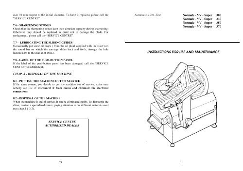
Automatic slicer - line: Normale - VV - Super 300<br />
Normale - VV - Super 330<br />
Normale - VV - Super 350<br />
Normale - VV - Super 370<br />
<strong>INSTRUCTIONS</strong> <strong>FOR</strong> <strong>USE</strong> <strong>AND</strong> <strong>MAINTENANCE</strong><br />
1
INTRODUCTION<br />
• This manual is meant to provide customers with information on the slicer and<br />
its specifications and the necessary operating and maintenance instructions in<br />
order to guarantee the best possible use of the machine and preserve its<br />
efficiency in the long term.<br />
• This manual is to be used by qualified and skilled people well informed about<br />
the use of the slicer and its periodical maintenance.<br />
CONTENTS<br />
CHAP. 1 - IN<strong>FOR</strong>MATION ON THE SLICER page 5<br />
1.1 - GENERAL PRECAUTIONS<br />
1.2 - SAFETY DEVICES INSTALLED ON THE SLICER<br />
1.2.1 - mechanical safety devices<br />
1.2.2 - electrical safety devices<br />
1.3 - SPECIFICATIONS OF THE SLICER<br />
1.3.1 - general description<br />
1.3.2 - construction characteristics<br />
1.3.3 - slicer components<br />
CHAP. 2 - TECHNICAL DATA page 8<br />
2.1 - OVERALL DIMENSIONS, WEIGHT, CHARACTERISTICS ...<br />
CHAP. 3 - THE ARRIVAL OF THE SLICER page 10<br />
3.1 - DESPATCH OF THE SLICER<br />
3.2 - PACKAGE CHECK UPON RECEIPT<br />
3.3 - PACKAGE DISPOSAL<br />
CHAP. 4 - INSTALLATION page.11<br />
4.1 - SETTING UP OF THE SLICER<br />
4.2 - ELECTRICAL CONNECTIONS<br />
4.2.1 - slicer with single-phase motor<br />
4.2.2 - slicer with 3-phase motor<br />
4.3 - ELECTRIC CIRCUIT DIAGRAMS<br />
4.3.1 - electric circuit diagram of normal automatic single-phase slicer<br />
4.3.2 - electric circuit diagram of normal automatic 3-phase slicer<br />
4.3.3 - electric circuit diagram ofsuper automatic three-phase, single-phase<br />
slicer<br />
2<br />
5. take the axis of the two holes (c) on the blade match with the two pivots (d) on<br />
the tool, simply making the blade turn until the desired position is reached;<br />
6. screw the two knobs (e) without though tightening too hard;<br />
6.2.3 - cleaning the sharpener<br />
Rub the sharpening stones with a small brush , still in safety position, i.e. with the<br />
sharpening stones towards the opposite side of the blade.<br />
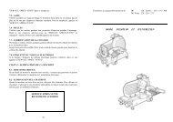
6.2.4 - cleaning the deflector<br />
To remove the deflector (see FIG. n°19) simply unscrew<br />
the two screws (a) that keep it blocked.<br />
At this point, clean the deflector with water and neutral<br />
detergents.<br />
CHAP. 7 - <strong>MAINTENANCE</strong><br />
FIG. n° 19 - View of the deflector<br />
7.1 - GENERAL FEATURES<br />
Before starting maintenance:<br />
a) always disconnect the power plug from the mains to completely isolate the<br />
slicer from the rest of the machine.<br />
b) turn the dial knob to adjust the thickness gauge plate to “0”.<br />
7.2 - BELT<br />
The belt does not need any adjusting. Generally, after 3/4 years it should be<br />
replaced; in this case, please contact the “SERVICE CENTRE”.<br />
7.3 - LEVELING FEET<br />
The leveling feet may deteriorate with time and loose their elasticity, thus reduces<br />
the stability of the slicer and they should be therefore regularly replaced.<br />
7.4 - POWER CORD<br />
Periodically check whether the power supply cord is worn out and, if so, please<br />
call the “SERVICE CENTRE” to have it replaced.<br />
7.5 - BLADES<br />
Check that the diamater of the blade, after many sharpenings, is not reduced by<br />
23<br />
a
- release the carriage from the automatic device by turning the lever (3)<br />
anticlockwise to position A (FIG.n°12);<br />
- unscrew the handwheel (4) and pull the<br />
b<br />
carriage upwards (b);<br />
- when the carriage has been removed, it is<br />
possible to clean the meat hopper with hot<br />
water and neutral detergent (PH7).<br />
FIG.n°16 - Release of the carriage<br />
6.2.2 - Cleaning the blade, the blade protection and the ring<br />
Unscrew the knob of the blade tightener (1) (see FIG. n°17) so as to remove the<br />
blade protection (2).<br />
FIG. n° 17 - Release of the blade<br />
WARNING:<br />
The blade should be cleaned wearing metallic gloves (3) and using a<br />
damp cloth. To clean the opposite surface of the blades and the ring, remove the<br />
blade (see FIG. n°18) from the slicer).<br />
Remove the blade as indicated below:<br />
1) unhook the protection (see FIG. n° 17);<br />
2) remove the sharpener (a) and slightly open<br />
the thickness gauge plate using the dial knob<br />
to make the blade removal tool (b) correctly<br />
a c<br />
f<br />
b<br />
e<br />
adhere to the blade;<br />
3) unscrew the 3 or 4 screws (according to the<br />
model) that fix the blade;<br />
4) place the plexiglas tool onto the blade, so that<br />
the opening on the tool matches the ring (c);<br />
d<br />
FIG. n° 18 - Positioning the blade removal tool<br />
3<br />
2<br />
22<br />
1<br />
a<br />
1<br />
3<br />
2<br />
4<br />
CHAP. 5 - <strong>USE</strong> OF THE SLICER page 16<br />
5.1 - CONTROLS<br />
5.2 - FUNCTIONING CHECK<br />
5.2.1 - normal automatic slicer<br />
5.2.2 - super automatic slicer<br />
5.3 - LOADING THE PRODUCT<br />
5.3.1 - VV and normal automatic slicer with automatic operation<br />
5.3.2 - VV and normal automatic slicer with manual operation<br />
5.3.3 - Super automatic slicer with automatic operation<br />
5.3.4 - Super automatic slicer with semi-automatic operation<br />
5.3.5 - Super automatic slicer with manual operation<br />
5.4 - SHARPENING OF THE BLADE<br />
CHAP. 6 - GENERAL CLEANING page 21<br />
6.1 - GENERAL FEATURES<br />
6.2 - CLEANING PROCEDURE<br />
6.2.1 - Cleaning the meat hopper<br />
6.2.2 - Cleaning the blade, the blade protection and the ring<br />
6.2.3 - Cleaning the sharpener<br />
6.2.4 - Cleaning the deflector<br />
CHAP. 7 - <strong>MAINTENANCE</strong> page. 23<br />
7.1 - GENERAL FEATURES<br />
7.2 - BELT<br />
7.3 - LEVELING FEET<br />
7.4 - POWER SUPPLY CORD<br />
7.5 - BLADE<br />
7.6 - SHARPENING STONES<br />
7.7 - LUBRICATION OF THE SLIDING GUIDES<br />
7.8 - LABEL OF THE PUSH-BUTTON PANEL<br />
CHAP. 8 - MACHINE DISPOSAL page 24<br />
8.1 - PUTTING THE MACHINE OUT OF SERVICE<br />
8.2 - DISPOSAL OF THE MACHINE<br />
3
INDEX OF FIGURES<br />
FIG. n°1 - General view of the slicer page 7<br />
FIG. n°2 - Overall dimensions page 8<br />
FIG. n°3 - Package description page 10<br />
FIG. n°4 - Rating plate - serial number page 11<br />
FIG. n°5 - Blade rotation page 12<br />
FIG. n°6 - Single-phase electric circuit diagram page 12<br />
FIG. n°7 - Three-phase electric circuit diagram page 13<br />
FIG. n°8 - Single and three-phase electric circuit diagram page 14<br />
FIG. n°9 - Table of adjustament values page 15<br />
FIG. n°10 - Location of controls on the normal automatic page 16<br />
slicer<br />
FIG. n°11 - Location of controls on the super automatic page 16<br />
slicer<br />
FIG. n°12 - Carriage lock/unlock lever page 17<br />
FIG. n°13 a-b - Correct cutting position page 18<br />
FIG. n°14 - Meat cut page 18<br />
FIG. n°15 a-b-c - Use of the sharpener page 20<br />
FIG. n°16 - Release of the carriage page 22<br />
FIG. n°17 - Release of the blade guard page 22<br />
FIG. n°18 - Positioning the blade removal tool page 22<br />
FIG. n°19 - View of the deflector page 23<br />
4<br />
6. after sharpening, the sharpening stones should be<br />
cleaned (see 6.2.3);<br />
7. once sharpening has been completed, put the<br />
sharpening device back in its initial position<br />
following the inverse procedure.<br />
N.B.: Deburring should not last longer than 3/4<br />
seconds in order not to deform the blade edge.<br />
CHAP. 6 - ORDINARY CLEANING<br />
6.1 - GENERAL FEATURES<br />
• The slicer should be cleaned at least once a day or more frequently, if<br />
necessary.<br />
• Cleaning should be extremely accurate on all the parts of the slicer that come<br />
into direct contact with the food.<br />
• Never clean the slicer by means of compressed water or water jets. Do not use<br />
other detergents. Also brushes and similar tools that may damage the<br />
appliance should not be used.<br />
Before cleaning:<br />
1) always disconnect the power plug from the mains to isolate completely the<br />
slicer from the rest of the machine;<br />
2) turn the dial knob to position "0";<br />
Pay attention to RESIDUAL RISKS due to cutting and/or sharp edges<br />
6.2 - SLICER CLEANING PROCEDURE<br />
6.2.1 - cleaning of the meat hopper (see FIG.n°16)<br />
The carriage (hopper+meat press+stem) can be easily removed:<br />
- with the dial knob on "0" (1);<br />
- with the carriage (2) at stroke-end (a) on the controls side;<br />
21<br />
3<br />
FIG. n°15b<br />
3<br />
FIG. n°15c<br />
4
7. at the end, press the switch-off button “0” of the blade and then the carriage<br />
switch-off button;<br />
8. resharpen the blade as soon as the slices have a frayed or rough surface and<br />
slicing becomes difficult (see 5.4).<br />
5.3.5 - Super automatic slicer with manual operation<br />
The procedure below is to be followed:<br />
1. load the product on the slicer and lock it with the meat press equipped with<br />
sharp edges;<br />
2. adjust the desired slicing thickness by means of the dial knob;<br />
3. turn the carriage unlocking knob to position A (FIG. n°12);<br />
4. turn the selector to MAN (FIG. n°11 - ref. 2);<br />
5. press the switch-on button “I” of the blade (FIG. n°11);<br />
6. once slicing has been carried out, press the switch-off button “0” of the blade<br />
(FIG. n° 11);<br />
7. resharpen the blade as soon as the slices have a frayed or rough surface<br />
andslicing becomes difficult (see 5.4).<br />
5.4 - BLADE SHARPENING (see FIG. n°15 a-b-c)<br />
Before proceding with blade sharpening, remain alert to the RESIDUAL<br />
RISKS (see §1.2.2) that refer to the hazard of injury if the instructions below<br />
are not followed.<br />
The blade should be re-sharpened each time slicing becomes difficult. To do this,<br />
the instructions indicated below are to be strictly followed:<br />
WARNING:<br />
very dangerous operation.<br />
1. unplug the slicer and carefully clean the blade<br />
using denatured alcohol, so as to degrease it;<br />
2. loosen the knob (1), lift the sharpening device (2)<br />
up to the block (a) and turn it by 180° (b) (see FIG.<br />
15a). Let it then reach the stroke end so that the<br />
blade lies between the twosharpening stones. Lock<br />
the knob;<br />
3. start the slicer by pressing the switch-on button “I”<br />
4. press the small button (3) (see FIG.15b), let the<br />
blade rotate against the sharpening stones for<br />
30/40 sec. to produce burr on the blade edge;<br />
5. press the buttons (3 and 4) simoultaneously and<br />
hold them for 3/4 seconds and then release them<br />
both together (see FIG. n°15c);<br />
20<br />
1<br />
a<br />
b<br />
FIG. n°15a<br />
2<br />
CHAP. 1 - IN<strong>FOR</strong>MATION ON THE SLICER<br />
1.1 - GENERAL PRECAUTIONS<br />
- The slicer must be operated only by highly qualified people who are fully<br />
aware of the safety measures described in this manual.<br />
- In case of a personnel turn over, training is to be provided in advance.<br />
- Although the slicer is equipped with safety devices in the dangerous points, it<br />
is recommended not to touch the blade and the moving components.<br />
- Before starting cleaning and maintenance, disconnect the slicer plug from the<br />
supply socket.<br />
- Assess the residual risks carefully when protection devices are removed to<br />
carry out cleaning and maintenance.<br />
- Cleaning and maintenance require great concentration.<br />
- A regular control of the electric supply cords is absolutely necessary; a<br />
worn-out or damaged cord can expose users to great electric shock hazard.<br />
- If the slicer shows malfunctions, it is recommended not to use it and to abstain<br />
from trying to repair it; please call the “SERVICE CENTRE”.<br />
- Do not use the slicer for frozen products, meat and fish with bones and any<br />
products other than foodstuffs.<br />
- Do not use the slicer without the help of the meat press, when the meat is<br />
nearly finished.<br />
- Do not place yourself in a dangerous position, the blade may cause<br />
injuries.<br />
The manufacturer is not liable in the following cases:<br />
⇒ if the slicer has been tampered by non-authorized personnel;<br />
⇒ if some parts have been substituted by non original spare parts;<br />
⇒ if the instructions contained in this manual are not followed accurately;<br />
⇒ if the slicer is not cleaned and oiled with the right products.<br />
1.2 - SAFETY SYSTEMS INSTALLED IN THE SLICER<br />
1.2.1 - MECHANICAL SAFETY SYSTEM<br />
The mechanical safety system of the slicer described in this manual complies<br />
with EC directives 89/392, mod. EC 91/368, 92/31, 93/44, 93/68 and regulations<br />
EN 1974.<br />
The safety system includes (see 1.3.3):<br />
- blade guard;<br />
- ring;<br />
- cover;<br />
- meat press<br />
- meat press knob with ring and spacer;<br />
- hand protection on the plate;<br />
5
- carriage only removable when the thickness gauge plate is set in the “0”<br />
position, at the end of its run and towards the operating side.<br />
1.2.2 - ELECTRICAL SAFETY SYSTEM<br />
The safety system installed to protect users against electrical risks is in<br />
compliance with EC directives 72/23, 89/336, mod. 91/368, 92/31, 93/68 and<br />
regulations EN 60335-1, EN 60335-2-64, EN 55014.<br />
The slicer is equipped with:<br />
- a micro-switch which stops the slicer in case the tie screw for blade guard is<br />
removed (see Fig. n° 1); the micro-switch prevents from restarting the slicer if<br />
the guard has not been set in the switch-off position.<br />
- a relay in the control box which requires the restarting of the slicer when a<br />
power cut occurs.<br />
Even though CE professional slicers are provided with electrical and mechanical<br />
protections (when the slicer is working and for maintenance and cleaning<br />
operations), there are still RESIDUAL RISKS (EC 89/392 point 1.7.2) that<br />
cannot be eliminated completely; these risks are mentionned in this manual under<br />
WARNING.The blade and other parts of the machine can cause cuts and injuries.<br />
1.3 - SPECIFICATIONS OF THE SLICER<br />
1.3.1 - general description<br />
Our firm has designed and manufactured the CE line of professional slicers to cut<br />
foodstuffs (as salami and meat) in order to guarantee:<br />
- the highest degree of safety in functioning, cleaning and maintenance;<br />
- the highest hygienic standards due to an accurate choice of materials and a<br />
smooth design of the slicer components which come into contact with products<br />
so as to obtain easy and total cleaning and easy disassembly;<br />
- the greatest accuracy in cutting foodstuffs thanks to a cam mechanism;<br />
- solidity and stability of components;<br />
- the highest degree of noiselessness due to belt drive;<br />
- great handiness.<br />
1.3.2 - construction features<br />
The professional slicers CE are made of an aluminium alloy (Peraluman Mg 5)<br />
treated by anodic oxidation. This procedure guarantees high hygienic standards of<br />
the parts interested by the cut and resistance to acids, salts and oxidation<br />
processes. The blade is made of chromium plated steel 100Cr6; it is grinded and<br />
hardened to guarantee an accurate and sharp cut of products also after it has been<br />
resharpened. The other components of the slicer are made of ABS, LEXAN,<br />
PLEXIGLAS and steel AISI 430 or 304.<br />
The edge is made of stainless steel and the inside frame is made of galvanized<br />
6<br />
1. load the product on the slicer and lock it with the meat press equipped with<br />
sharp edges;<br />
2. set the slicing thickness by means of the dial knob;<br />
3. press the switch-on button “I” of the blade (FIG. n° 10 - ref. 1);<br />
4. in the VV model it is possible to adjust the speed using a small knob;<br />
5. push the carriage (meat hopper + meat press + stem) and slightly advance it<br />
towards the blade, without pressing the product against the thickness gauge<br />
plate (by gravity). The product will easily penetrate through the blade, and the<br />
slice, guided by the deflector, will fall onto the collecting tray (see FIG. n°14);<br />
6. do not let the slicer work when unloaded;<br />
7. at the end of the slicing, turn the dial knob to “0”,and press the switch-off<br />
button “0” of the blade to stop the slicer (FIG. n° 10 - ref. 2);<br />
8. resharpen the blade as soon as the slices have a frayed or rough surface and<br />
slicing becomes difficult (see 5.4).<br />
5.3.3 - Super automatic slicer in automatic mode<br />
The procedure below is to be followed:<br />
1. load the product on the slicer and lock it with the meat press equipped with<br />
sharp edges;<br />
2. adjust the desired slicing thickness by means of the dial knob;<br />
3. turn the selector to AUTO (FIG. n°11 - ref. 2);<br />
4. set the number of slices desired by means of the selector (FIG. n°11 - ref. 7);<br />
5. press the switch-on button “I” of the blade;<br />
6. press the switch-on button “I” of the carriage;<br />
7. set the carriage speed by using the appropriate knob (FIG. n°11 - ref. 1); the<br />
display will progressively show the number of slices cut;<br />
8. resharpen the blade as soon as the slices have a frayed or rough surface and<br />
slicing becomes difficult (see 5.4).<br />
5.3.4 - Super automatic slicer in semi-automatic mode<br />
The procedure below is to be followed:<br />
1. load the product on the slicer and lock it with the meat pusher equipped with<br />
sharp edges;<br />
2. adjust the desired slicing thickness by means of the dial knob;<br />
3. turn the selector to MAN (FIG. n° 11 - ref. 2);<br />
4. press the switch-on button “I” of the blade;<br />
5. press the switch-on button “I” of the carriage;<br />
6. set the carriage speed by using the appropriate knob (FIG. n°11 - ref. 1); the<br />
display will progressively show the number of slices cut;<br />
19
5.3 - LOADING THE PRODUCT<br />
The product is to be loaded on the meat hopper only with the dial knob in position<br />
“0” and with the slicer off, paying attention to the blade and to the sharp edges.<br />
N.B.: to avoid accidents, the person who is cutting has to face the machine and<br />
stand correctly: put the right hand on the meat press, and then the left one beside<br />
the deflector (do not touch the blade); the body must be perpendicular to the<br />
working surface (see FIG.n°13a).<br />
Pay the maximum attention: no part of your body should enter in contact<br />
with the blade (see FIG. n°13b);<br />
FIG: n°13a - Right position FIG. n°13b - Wrong position FIG. n°14 - Meat cut<br />
5.3.1 - VV and Normal automatic slicer in automatic mode<br />
The procedure below is to be followed:<br />
1. load the product on the slicer and lock it with the meat press equipped with<br />
sharp edges;<br />
2. set the slicing thickness desired by means of the dial knob;<br />
3. the carriage unlocking lever should be turned in position B (FIG. 12);<br />
4. press the switch-on button “I” of the blade (FIG. n° 10 - ref. 1);<br />
5. then press the switch-on button “I” of the carriage (FIG. n° 10 - ref. 3); in<br />
the VV model it is possible to adjust the speed using a small knob;<br />
6. do not let the slicer work when unloaded;<br />
7. at the end of slicing, turn the dial knob to “0”, press the switch-off button “0”<br />
of the carriage (FIG. n° 10 - ref. 4) and then press the switch-off button “0” of<br />
the blade;<br />
8. resharpen the blade as soon as the slices have a frayed or rough surface and<br />
slicing becomes difficult (see 5.4, FIG.15a-b-c).<br />
5.3.2 -VV and Normal automatic slicer in manual mode<br />
N.B.: to work in manual mode, unlock the carriage by turning the carriage<br />
unlocking lever to position A (FIG. n° 11); in this way, the carriage and the upper<br />
keypad may be normally used as any manual slicer;<br />
18<br />
iron.<br />
1.3.3 - appliance configuration<br />
FIG. n°1 - General view of the slicer<br />
10<br />
13<br />
9<br />
23<br />
11<br />
12<br />
1<br />
2<br />
24<br />
17<br />
18<br />
20<br />
7<br />
8<br />
19<br />
7<br />
6<br />
14<br />
2<br />
3<br />
16<br />
4<br />
15<br />
21<br />
5<br />
22
LEGEND:<br />
1 - Hand guard 12 - Tie screw for blade guard<br />
2 - Meat press arm 13 - Leveling feet<br />
3 - Blade guard 14 - Push-button panel<br />
4 - Sliding food hopper 15 - Dial knob<br />
5 - Edge 16 - Thickness gauge plate<br />
6 - Stem 17 - Deflector<br />
7 - Carriage locking knob 18 - Rating plate - serial number<br />
8 - Mechanism lever 19 - Blade<br />
9 - Thickness gauge plate 20 - Ring<br />
10 - Sharpener cover 21 - Fixed meat hopper<br />
11 - Sharpener locking knob 22 - Shell<br />
23 - Base<br />
24 - Stem lever<br />
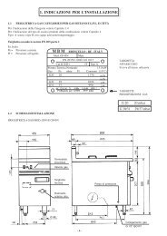
CHAP. 2 - TECHNICAL DATA<br />
2.1 - OVERALL DIMENSIONS, WEIGHT, CHARACTERISTICS...<br />
FIG. n°2 - Overall dimensions<br />
D<br />
A<br />
8<br />
E<br />
B<br />
C<br />
Manual operation<br />
Unlock the carriage by turning the knob to position A (see FIG.n°12):<br />
7. press the switch-on button “I” and the switch-off button “0” of the blade;<br />
8. check the manual sliding of the carriage.<br />
A<br />
B<br />
Carriage lock/unlock lever<br />
A - Carriage unlocked<br />
B - Carriage locked<br />
FIG. n° 12 - Carriage lock/unlock lever<br />
5.2.2 - SUPER AUTOMATIC slicer<br />
1. turn the selector on AUTO (FIG. n° 11 - ref. 2);<br />
2. check the functioning and the adjustment of the thickness gauge plate by using<br />
the dial knob (FIG. n°1 - ref. 15);<br />
3. Check the functioning of the sharpener (see para. 5.4, FIG. 15 a-b-c);<br />
4. check that the carriage can be removed only with the knob in position “0” and<br />
that, after removal, the knob remains in the same position;<br />
5. set a random number of slices on the selector (FIG. n°11 - ref. 7);<br />
6. press the blade switch-on button (FIG. n°11 - ref. 4) and then the carriage<br />
switch-on button (FIG. n°11 - ref. 5), making sure that they both work<br />
correctly;<br />
7. check whether display indicates the number of slices cut;<br />
8. make sure that the slicer shuts down automatically when the preset number of<br />
slices has been reached.<br />
Semi-manual operation mode<br />
9. turn the selector on MAN;<br />
10. press the switch-on button “I” (FIG. n°11 - ref. 4);<br />
11. check that the display indicates the number of slices cut;<br />
12. once the preset number of slices has been reached, turn off the slicer.<br />
Manual operation mode<br />
13. turn the selector on MAN (FIG. n°11 - ref. 2);<br />
14. unlock the carriage by turning the knob in position A (FIG. n° 12);<br />
15. press the blade switch-on button “I” and then the switch-off button “0”;<br />
16. check the manual sliding of the carriage and of the meat press;<br />
17
CHAP. 5 - <strong>USE</strong> OF THE SLICER<br />
5.1 - CONTROLS<br />
Controls are located on the left side of the base.<br />
Controls of VV and Normal automatic slicer:<br />
1. “I” blade ON push-button.<br />
2. “0” blade stop push-button.<br />
3. “I” carriage ON push-button.<br />
4. “0” carriage stop push-button.<br />
FIG. n° 10 - Location of controls on the Normal automatic<br />
Controls of the Super automatic slicer:<br />
1. Carriage speed adjusting knob<br />
2. Selector for manual (MAN) or automatic (AUTO)<br />
operating mode.<br />
3. Number of slices display.<br />
4. “I” blade ON push-button.<br />
5. “I” carriage ON push-button (CAR).<br />
6. “0” blade and carriage stop push-button.<br />
7. Number of slices selector.<br />
FIG. n°11 - Location of controls on the Super automatic slicer<br />
16<br />
3<br />
2<br />
4<br />
3<br />
1<br />
2<br />
4 5 6<br />
5.2 - FUNCTIONING CHECK<br />
Before carrying out testing, make sure the meat hopper is correctly locked with<br />
the knob in position B ( see FIG. n°12)<br />
and then test the slicer<br />
5.2.1 - VV and NORMAL AUTOMATIC slicer<br />
1. press the switch-on button “I” and the switch-off button of the blade;<br />
2. check the carriage functioning by pressing the switch-on button “I” and then<br />
the switch-off button; a special device allows automatic operation only with<br />
the slicer turned on. Repeat step 1;<br />
3. check the operation and the adjustment of the thickeness gauge plate by means<br />
of the dial knob;<br />
4. check the functioning of the sharpener (see par. 5.4, FIG. n°15a-b-c);<br />
5. check that the carriage can be removed only with the dial knob set in position<br />
“0” and after disassembling, the knob cannot be turned;<br />
6. check that the slicer stops functioning by unscrewing the tie screw for blade<br />
guard.<br />
7<br />
1<br />
TAB. n°1 - OVERALL DIMENSIONS <strong>AND</strong> TECHNICAL CHARACTERISTICS<br />
MODEL U.m. NORMALE 300 - 330 - 350 - 370<br />
VV 300 - 330 - 350 - 370<br />
SUPER 300 - 330 - 350 - 370<br />
Blade diametre mm. 300 330 350 370<br />
Length A mm. 665 690 760 765<br />
Width B mm. 635 635 655 695<br />
Height C mm. 730 730 810 810<br />
Distance between feet D mm. 475 475 555 555<br />
Distance between feet E mm. 320 320 370 370<br />
Hopper size mm. 300 x 240 300 x 240 320 x 285 320 x 285<br />
Carriage run mm. 285 295 355 355<br />
Capacity of the cut mm. 210 x 235 235 x 235 250 x 280 260 x 285<br />
Thickness of the cut mm. 0 ÷ 14 0 ÷ 14 0 ÷ 14 0 ÷ 14<br />
Blade turns (g/l) 300 300 300 300<br />
Motor W<br />
W<br />
W<br />
Power supply Mn<br />
Tf<br />
Weight Kg<br />
Kg<br />
Kg<br />
N. 529<br />
VV 391<br />
S. 395<br />
N. 48<br />
VV 50<br />
S. 50<br />
9<br />
N. 529<br />
VV 391<br />
S. 395<br />
N. 586,5<br />
VV 586,5<br />
S. 586,5<br />
230 V. / 50 Hz<br />
230-400 V. / 50 Hz<br />
N. 49,5<br />
VV 51,5<br />
S. 50,5<br />
N. 64,5<br />
VV 64,5<br />
S. 64,5<br />
N. 586,5<br />
VV 439,3<br />
S. 439,3<br />
N. 65,5<br />
VV 65,5<br />
S. 67,5<br />
Nr. of slice/min N°/min. 30 30 30 30<br />
Noise level dB ≤ 65 ≤ 65 ≤ 65 ≤ 65<br />
WARNING<br />
: The electrical characteristics for which the appliance is designed<br />
are indicated on the reference plate applied on the side of the appliance; before<br />
connecting to power supply, please read par. 4.2.
CHAP. 3 - THE ARRIVAL OF THE SLICER<br />
3.1 - DESPATCH OF THE SLICER (see FIG. n°3)<br />
Slicers are accurately packed and then despatched from our warehouses; the<br />
package includes: a) a strong cardboard box;<br />
b) the slicer;<br />
c) two cardboard filling grafts to keep the slicer stable;<br />
d) blade removal tool<br />
e) this manual;<br />
f) an oil phial;<br />
g) EC conformity declaration.<br />
e)<br />
FIG. n°3 - Package description<br />
d)<br />
a)<br />
c)<br />
10<br />
g)<br />
b)<br />
f)<br />
Adjustment procedure<br />
Fuses: IF extra-rapid = 1,5 I MOTOR<br />
Trimmer adjustment (values indicated)<br />
FIG. n° 9 - Table of the adjustment values<br />
1) MAX SPEED: according to the nominal speed of the motor;<br />
2) ACCEL: according to system requirements;<br />
3) IR COMP: starting from zero, increase the adjustment without reaching<br />
overcompensation, which causes instability;<br />
4) CURR LIM TORQUE: it limitates the current transmitted to the motor; adjust<br />
on Imax
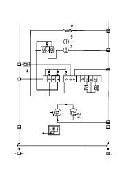
4.3.3 - Electric circuit diagram of Super automatic Three-phase and Singlephase<br />
slicer<br />
FIG. n°8 - Electric circuit diagram of the Super automatic Three-phase and<br />
single-phase slicer<br />
14<br />
3.2 - PACKAGE CHECK UPON RECEIPT<br />
If no external damage is evident on the package upon its arrival, open it and<br />
check that all the components are inside (see FIG. n° 3). If the package has<br />
suffered from rough handling, bumps or crashes, the carrier must be informed<br />
about any damage; moreover a detailed report on the extent of the damage caused<br />
to the machine must be filled within three days from the delivery date shown in<br />
the shipping documents.<br />
Do not overturn the package!! When the package is transported, make sure, the<br />
box is lifted by the 4 corners (parallel to the ground)<br />
3.3 - PACKAGING DISPOSAL<br />
The components of the packaging (cardboard box, pallets, plastic straps and<br />
polyurethane) are urban solid waste; therefore they can be easily disposed.<br />
If the slicer is to be installed in countries where specific regulations are in force,<br />
packaging must be disposed in compliance with them.<br />
CHAP. 4 - INSTALLATION<br />
4.1 - SETTING UP OF THE SLICER<br />
The slicer must be installed upon a working table suitable for the slicer’s overall<br />
dimensions shown in Table 1 (according to the model); therefore it must be<br />
adequately large, well levelled, dry, smooth, resistent, stable and placed at a<br />
height of 80 cm from the ground.<br />
Moreover the machine must be installed in a room with max. 75% not saline<br />
humidity at a temperature between +5°C and 35°C; that is to say in a place that<br />
does not provoke the slicer failure.<br />
4.2 - ELECTRICAL CONNECTIONS<br />
4.2.1 - slicer with single-phase motor<br />
The slicer is equipped with a power supply cord (section of 3x1mm² and length of<br />
1.5m) and a “SHUKO” plug.<br />
Connect the slicer with a 230 Volt - 50 Herz electric circuit by interposing a<br />
differential- magnetothermic switch of 10A, ΔI = 0,03A. Check that the earthing<br />
is fully operational. Moreover check that features on the rating plate - serial<br />
number (FIG. n°4) correspond to the features shown in the consignment and<br />
delivery note.<br />
FIG. n°4 - Rating plate - serial number<br />
11
4.2.2 Slicer with 3-phase motor<br />
The slicer is equipped with a power supply cord with a section of 5x1mm²and a<br />
length of 1.5m.<br />
Connect the slicer with a 400 Volt - 50 Herz three-phase electric circuit by means<br />
of a CEI plug interposing a differential-magnetothermic switch of 10A., ΔI =<br />
0,03A.. Check that the earthing is fully operational. Before connecting the<br />
machine to the three-phase power supply circuit, check the direction of blade<br />
rotation by pushing the button “I” (ON) (see CHAP. 5.1 FIG. n°8) and<br />
immediately afterwards the cut-off button “0” (OFF).<br />
The blade rotation must be anti-clockwise looking at the machine from the blade<br />
guard side (see FIG: n°5).<br />
If the otation is wrong, reverse two of the three power<br />
supply cords in the plug or in the socket (black and grey).<br />
Three-phase motors installed in CE professional slicers<br />
can work with both 230 V.three-phase tension and 400 V<br />
tension.<br />
Unless otherwise specified, connections are made with 400<br />
V. power supply; call the “SERVICE CENTRE” if<br />
matching with the 230 V three-phase circuit. is required.<br />
4.3 - ELECTRIC CIRCUIT DIAGRAMS<br />
4.3.1 - electric circuit diagram of the Normal automatic Single-phase slicer<br />
12<br />
FIG.n°5 - Blade rotation<br />
FIG. n°6 - Electric circuit diagram of Normal automatic Single-phase slicer<br />
4.3.2 - electric circuit diagram of the Normal automatic Three-phase slicer (see<br />
FIG. n°7)<br />
FIG. n°7 - Electric circuit diagram of normal automatic Three-phase slicer<br />
13