WIRELESS
Dynamic Channel Modeling at 2.4 GHz for On-Body Area Networks
Dynamic Channel Modeling at 2.4 GHz for On-Body Area Networks

You also want an ePaper? Increase the reach of your titles
YUMPU automatically turns print PDFs into web optimized ePapers that Google loves.
Dynamic Channel Modeling at 2.4 GHz for<br />
On-Body Area Networks<br />
Lingfeng Liu, Raffaele D’Errico, Laurent Ouvry, Philippe De Doncker, and Claude Oestges<br />
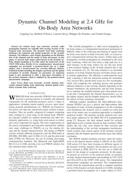
Abstract—In wireless body area networks, on-body radio<br />
propagation channels are typically time-varying, because of the<br />
frequent body movements. The dynamic local body scattering<br />
dominates the temporal and spatial properties of the on-body<br />
channels. The influence varies largely depending on the distribution<br />
of the channels and the modes of body movements. In this<br />
paper, we present some major achievements on the dynamic onbody<br />
channel modeling at 2.4 GHz under the framework of the<br />
COST 2100 action. Results of two complementary measurement<br />
campaigns are presented: a geometry-based one on a single<br />
subject, and a scenario-based one covering different subjects.<br />
Statistical models includingthe Doppler spectrum and the spatial<br />
correlation of on-body channels are presented. An analytical<br />
model is also introduced to offer a time-space description of<br />
the on-body channels, which is validated by the geometry-based<br />
measurement campaign.<br />
Index Terms—Body area networks, on-body channel, timevariant<br />
channel fading, body shadowing, channel spatial correlation,<br />
dynamic body scattering<br />
I. INTRODUCTION<br />
<strong>WIRELESS</strong> body area networks (WBANs) have recently<br />
received a growing interest in scientific and industrial<br />
communities by the promising prospects across a range of<br />
applications, including remote medical services, sport monitoring,<br />
personal entertainments, etc.. WBANs are featured as<br />
low-power, low data rate, and person-centric wireless communications.<br />
They are usually composed of compact computing<br />
units working in a close range of the human body. WBANs<br />
are typically suitable for medical monitoring and other biotelemetry<br />
applications, i.e. using body-worn sensors to collect<br />
and convey important bio-signals. The strict requirements on<br />
the power consumption and long-term transmission stability<br />
raise many challenges to WBANs on e.g. the antenna design<br />
and the channel characterization. The design of WBAN<br />
systems includes different frequencies, like the ISM bands at<br />
400 MHz, 900 MHz, and 2.4 GHz [1]–[3], and the ultra-wide<br />
band (UWB) [4]. Moreover, the use of existing short-range<br />
communication standards, like Bluetooth and Zigbee/IEEE<br />
802.15.4 at 2.4 GHz, provide a low-cost WBAN solution, has<br />
also attracted many studies [5].<br />
L. Liu is with ICTEAM Electrical Engineering, Université catholique de<br />
Louvain, BELGIUM, and OPERA, Université libre de Bruxelles, BELGIUM.<br />
email: lingfeng.liu@uclouvain.be<br />
R. D’Errico and L. Ouvry are with CEA, LETI, MINATEC 17 rue des<br />
Martyrs 38054 Grenoble Cedex 9, FRANCE. emails: raffaele.derrico@cea.fr,<br />
laurent.ouvry@cea.fr<br />
P. De Doncker is with OPERA, Université libre de Bruxelles, BELGIUM.<br />
email: pdedonck@ulb.ac.be<br />
C. Oestges is with ICTEAM Electrical Engineering, Université catholique<br />
de Louvain, BELGIUM. email: claude.oestges@uclouvain.be<br />
Manuscript submitted May 30, 2011; revised July 18, 2011<br />
The on-body propagation, i.e. radio waves propagating on<br />
the body surface, is a fundamental transmission mechanism in<br />
WBANs, either in the collecting and relaying of signals from<br />
the body-worn sensors to body-worn data sinks, or in peer-topeer<br />
communications between the sensors. Unlike large-scale<br />
propagation, on-body propagation are dominated by the local<br />
body scattering, which not only forms a high path loss in a<br />
short distance on the body surface [3], [4], but also forms<br />
a time-variation (fading) of the on-body channels due to the<br />
body movements [2], [3]. The time-variation is an inevitable<br />
property of on-body channels because our bodies always move<br />
in realistic applications. The difficulty to understand the local<br />
body scattering is that the interaction among the transmitter<br />
(Tx), receiver (Rx), and the body occurs in a few wavelengths,<br />
which will complicate the scattering process and generates<br />
different influences to the on-body channels depending on the<br />
channel distribution, the polarization, and the body posture,<br />
not to mention the modified antenna gain when placed close<br />
to the skin. Consequently, the channel characteristics, e.g. on<br />
the fading variance and the Doppler dispersion, should reflect<br />
the effects of body scattering consistently.<br />
Although complex simulations like finite-difference timedomain<br />
(FDTD) can give a precise and high-solution field<br />
description of static on-body propagation as in [6], extending<br />
such simulations into dynamic cases is usually too costly that<br />
most of the studies stay on statistical approaches or simplified<br />
analytical models. The dynamic on-body channels have also<br />
been partly addressed by the IEEE 802.15.6 standardization<br />
group [7]. However, the final channel model for on-body<br />
applications in [8], is mainly focused on static scenarios. Other<br />
studies like [9], [10], were limited by their test-beds and<br />
the understanding of the on-body propagation mechanisms,<br />
which exclude some critical aspects of the dynamic on-body<br />
channels, like the Doppler spectrum and the space-time fading<br />
correlation.<br />
The WBAN channel modeling activities under the framework<br />
of the Special Interest Group E (SIG-E) of the COST<br />
2100 action [11] have been focusing on different aspects of<br />
the dynamic on-body channels. The researches not only cover<br />
those featured in IEEE 802.15.6, but also try to fulfill the<br />
needs for the design of cooperative protocols. In this paper,<br />
we present an overview of the achieved results on dynamic<br />
on-body channel characterization and modeling by UCL-ULB<br />
and CEA-LETI in the COST 2100 action. Two independent<br />
measurement campaigns are presented. The complementary<br />
results from the measurements provide a complete statistical<br />
survey of the dynamic on-body channels at 2.4 GHz, including<br />
a geometry-based investigation on a single subject in UCL-
LIU et al.: DYNAMIC CHANNEL MODELING AT 2.4 GHZ FOR ON-BODY AREA NETWORKS 19<br />
trunk surface<br />
0.5 cm<br />
TABLE I<br />
SETUPS AND HUMAN BODY CHARACTERIZATION OF MEASUREMENT<br />
CAMPAIGN 1<br />
(a)<br />
antenna<br />
(b)<br />
dialetric block<br />
connector<br />
Fig. 1. Antennas in measurement setup 1, (a) shows the antenna structure<br />
where the arrow indicates the antenna polarization, (b) describes the antenna<br />
emplacement on the trunk surface<br />
(a)<br />
RIGHT<br />
3<br />
d 23<br />
d 13<br />
0<br />
d 20<br />
S 32<br />
S 31<br />
S 21<br />
(b)<br />
2<br />
d 10<br />
d 12<br />
1<br />
LEFT<br />
Fig. 2. Measurement setup 1: (a) measured channels where 1, 2, 3 represent<br />
the antennas and 0 represents the trunk center; (b) geometric quantization<br />
of the scenarios, where S xy with x, y = 1, 2, 3, represents the investigated<br />
channel with Tx, y, and Rx, x, d y0 is the transmitter absolute position, and<br />
d xy is the propagation distance on the trunk surface.<br />
ULB, and a scenario-based one on multiple subjects in CEA-<br />
LETI. An analytical model is also introduced to provide a<br />
physical time-space description of the on-body channels with<br />
respect of small-scale body movements.<br />
The paper is organized as follows, Sec. II describes the<br />
context of the two measurement campaigns, Sec. III to Sec.<br />
V present the statistical characterization and modeling of the<br />
time-varying channel fading, Sec. VI introduces the analytical<br />
model, and Sec. VII offers some conclusive comments on the<br />
present work.<br />
II. MEASUREMENTS CONTEXT<br />
In this section, we present the contexts of two on-body<br />
channel measurement campaigns carried out at UCL-ULB<br />
and CEA-LETI respectively. The two measurement campaigns<br />
differ in terms of the test-beds, the scenarios, and the analyzing<br />
methods. Still, the collected results enable complementary<br />
approaches in on-body channel characterization.<br />
A. Measurement setup 1<br />
The measurement campaign from UCL-ULB was carried<br />
out in a quasi-anechoic environment. Three linearly polarized<br />
antennas (Skycross SMT-3TO10M), as depicted in Fig. 1(a),<br />
were attached on the front side of the trunk of a male subject.<br />
The antennas were tangentially polarized to the skin along the<br />
vertical direction, as in Fig. 1(b). The antennas were fixed 5<br />
mm away from the skin to avoid a decrease of the antenna<br />
efficiency by the body coupling effects [3].<br />
We used a multi-ports vector network analyzer (VNA) to<br />
measure the transmission S-parameters among the antennas as<br />
the channel measurements. The antennas and the VNA were<br />
connected through stable coaxial cables. The current influence<br />
Frequency 2.45 GHz IF Bandwidth 10 kHz<br />
Input power 0 dBm Sweep mode CW<br />
Measurement length 10 s Sampling rate 1 ms<br />
Body height 183 cm Body weight 80 Kg<br />
Body trunk radius (ρ body ) 14.5 cm Arm radius (ρ arm) 4.2 cm<br />
Arm-body spacing (d ab ) 3 cm Antenna height 122 cm<br />
from the cables was found ignorable to the measurements. The<br />
measurements were conducted in continuous wave (CW) mode<br />
over time at 2.45 GHz. Each measurement piece with fixed<br />
positions of the antennas contains 10 seconds observation at<br />
a sampling rate of 1 ms.<br />
During the measurements, the subject was asked to stand<br />
on the ground and swing the arms to mimic the typical arm<br />
movement during walk. The arms swing in quasi-periodic way,<br />
which bring the dominant dynamic body-scattering effect to<br />
the investigated on-body channels.<br />
The goal of this measurement campaign was to investigate<br />
different on-body channels by means of measurable geometry,<br />
i.e. a quantized geometric description of the channel distribution<br />
on the body. The statistics of the time-varying narrowband<br />
on-body fading can then be related with the channel geometry<br />
to enable a canonical characterization and modeling. In Fig.<br />
2(a), the antennas were placed at the same height, forming<br />
horizontal on-body channels around the trunk. Each channel<br />
is then described explicitly by its Tx-Rx propagation distance<br />
measured on the trunk surface, and the relative position of<br />
the Tx to the trunk center. Fig. 2(b) describes the geometry<br />
quantization of the channels. Considering the channel distribution<br />
(front side of trunk) and the dominant body scattering<br />
(arm swing), the geometry of the body can be described by<br />
the radii of the arms (ρ arm ) and the trunk (ρ body ), and the<br />
space between the arms and the trunk (d ab ). The details of the<br />
measurement settings are listed in Table I.<br />
B. Measurement setup 2<br />
The measurement campaign from CEA-LETI was carried<br />
out in both anechoic chamber and indoor environments [12].<br />
The test-bed was composed of a pulse step generator, a<br />
wideband real-time digital oscilloscope Tektronix TDS6124C,<br />
a power amplifier at Tx (about 35 dB in the band of interest),<br />
and several low-noise amplifiers at Rx (42 dB gain and noise<br />
figure of 2 dB), to obtain a distributed single-input-multipleoutput<br />
(SIMO) configuration. The test-bed can simultaneously<br />
collect up to four channel impulse responses (CIRs) coming<br />
from different locations on the body. The CIRs were collected<br />
every 20 ms, each one enhanced by averaging 30 CIRs to<br />
improve the signal-to-noise ratio (SNR) of the measurements.<br />
Measurements were investigated in a large band, including 2.4<br />
GHz and 3-5 GHz part of the UWB. In this paper, we focus<br />
only on the results at 2.4 GHz.<br />
The employed antennas were compact 30 mm × 40 mm<br />
UWB antennas derived from [13], which were fixed at 5 mm<br />
away from the skin by dielectric foam blocks. Three different
20 ADVANCES IN ELECTRONICS AND TELECOMMUNICATIONS, VOL. 2, NO. 4, DECEMBER 2011<br />
−20<br />
µ<br />
SA(µ)<br />
−40<br />
dB<br />
−60<br />
−80<br />
−100<br />
0 5 10 15 20 25 30 35 40<br />
Propagation distance [cm]<br />
(a) Mean µ<br />
Fig. 3.<br />
[12]<br />
Measured channels in setup 2: TX on Hip (left), TX on Ear (right)<br />
7<br />
6<br />
5<br />
σ<br />
SA(σ)<br />
modes of body movements were investigated: standing still,<br />
walking, and running on a spot. Two sets of measurements<br />
were performed according to the antenna locations as depicted<br />
in Fig.3. In the first set, the Tx was on “Hip” (left side) and<br />
we collected simultaneously the received signals on “Chest”,<br />
“Right Thigh”, “Right Wrist” and “Right Foot”. In the second<br />
set, the Tx was placed on “Left Ear” and we collected simultaneously<br />
the received signals on “Right Ear”, “Hip”, ”Right<br />
Wrist” and ”Right Foot”. The variability of the human bodies<br />
was taken into account by repeating the measurements on 7<br />
different subjects: heights from 1.69 m to 1.89 m, and weights<br />
from 58 kg to 79 kg. The non-homogeneity of the human body,<br />
and the variability of different subjects, suggest a scenariobased<br />
channel characterization and modeling, with respect<br />
to the locations of the antennas, the body movements, and<br />
the surrounding environment. The scenario-based approach<br />
identifies a specific scenario in measurement campaign 2 by:<br />
• the T X ∈ {Hip, Left Ear}<br />
• the RX ∈ {Hip, Chest, Right Wrist, Right Thigh, Right<br />
Foot, Right Ear }<br />
• the movement m ∈ {Still, Walking, Running}<br />
• the environment e ∈ {Anechoic, Indoor}<br />
In brief, a particular scenario in measurement campaign 2 is<br />
noted as S = {T X, RX, m, e}. The channel characterization<br />
and modeling are then specified to each scenario [14].<br />
III. FADING STATISTICS AND MODELING<br />
The narrowband channel fading is the time-variation of the<br />
channel. The time-variation of on-body channels can be caused<br />
by the following reasons: the dynamic body scattering, the<br />
multipath (MPC) effects from the off-body scattering, and<br />
the modifications of the antenna properties during the body<br />
movements and the change of body postures. The issue of<br />
antenna de-embedding is not covered in this paper, yet it is<br />
important to obtain the correct physical on-body channels from<br />
the measurements.<br />
The geometry-based measurement campaign 1 does not distinguish<br />
the fast fading and slow fading (shadowing) defined<br />
in conventional large-scale propagation, because there is no<br />
clear physical mechanism to strictly specify the two different<br />
fadings when only the dynamic body scattering is considered<br />
dB<br />
4<br />
3<br />
2<br />
1<br />
0<br />
0 5 10 15 20 25 30 35 40<br />
Propagation distance [cm]<br />
(b) STD σ<br />
Fig. 4. Mean µ and STD σ of fading amplitude on a dB scale over the<br />
propagation distance, measurement campaign 1<br />
SA(χ 2 )<br />
5<br />
4<br />
3<br />
2<br />
1<br />
Lognormal<br />
Normal<br />
Nakagami<br />
Exponential<br />
Gamma<br />
Weibull<br />
Rayleigh<br />
Rice<br />
0<br />
0 5 10 15 20 25 30 35 40<br />
Propagation distance [cm]<br />
Fig. 5. SA[χ 2 ] comparison of various distribution estimations of the fading<br />
amplitude on a linear scale, measurement campaign 1<br />
in the scenarios. The statistics of the horizontal on-body channels<br />
are then extracted from each measurement piece (10 s).<br />
In measurement campaign 1, the mean and standard deviation<br />
(std) of the channel fading amplitude are computed on dB<br />
scale, i.e. µ = E[|S xy | dB (t n )] and σ = ST D[|S xy | dB (t n )].<br />
Fig. 4 presents the measurement results of µ and σ, which are<br />
sorted by the propagation distance d xy described in Fig. 2. In<br />
Fig. 4, each point at a given propagation distance represents<br />
a channel at a specific position. The different positions of<br />
the channels causes a spatial variation of µ and σ at each<br />
d xy . The spatial average (SA) of µ and σ, i.e. the averaged<br />
values of µ and σ at each d xy , are also plotted in Fig. 4, to<br />
describe the average trends of µ and σ along d xy . The results<br />
show a linear decrease of µ, i.e. a path loss of 1.68 dB/cm<br />
for on-body propagation around the trunk in tangential z-<br />
polarization. A linear increase of σ at 0.09 dB/cm is observed<br />
when d xy < 30cm, and a faster increase when d xy is above<br />
30 cm. The faster increase of σ of channels longer than 30
LIU et al.: DYNAMIC CHANNEL MODELING AT 2.4 GHZ FOR ON-BODY AREA NETWORKS 21<br />
cm may due to an enhancement of non-line-of-sight (NLOS)<br />
propagation and a relatively increasing impact from the arm<br />
scattering to the channels.<br />
The maximum likelihood estimator (MLE) is applied to<br />
compare the following distribution models of the fading amplitudes<br />
on linear scale in measurement campaign 1: Lognormal,<br />
Normal, Exponential, Weibull, Gamma, Nakagami, Rayleigh,<br />
and Rice. The Chi-square value, χ 2 , is taken as the good-offitness<br />
test for the estimations.<br />
For clarity, Fig. 5 compares the SA of χ 2 of different<br />
distribution estimations over the d xy . It shows that within the<br />
range of the investigated propagation distances, the Lognormal<br />
distribution is among the best candidates to describe the<br />
distribution of fading amplitude on linear scale, i.e. normal<br />
distribution on dB scale. A similar conclusion can be found<br />
in [15] for static scenarios.<br />
The scenario-based measurement campaign 2 distinguishes<br />
the shadowing/slow fading S(t n ) and the fast fading F(t n ) in<br />
the measured time-dependent power transfer function P(t n )<br />
by the conventional definition:<br />
P(t n ) = G 0 · S(t n ) · F(t n ), (1)<br />
where G 0 is the path loss based on each measurement piece.<br />
Examples of P(t n ) and G 0 · S(t n ) are demonstrated in Fig. 6,<br />
showing that the shadowing strictly depends on the movement<br />
mode. When the subject is in still scenarios, the slow varying<br />
component of P(t n ) is very small, since the shadowing<br />
condition of the body remains stationary.<br />
The results from measurement campaign 2 show that the<br />
path loss on dB scale, G 0 | dB , is a Gaussian random variable.<br />
The variance of G 0 | dB accounts for the dissimilarities among<br />
the human body investigated, and the local displacements of<br />
the antennas due to the different body shapes:<br />
G 0 | dB ∼ N (µ 0S , σ 0S ). (2)<br />
In Table II and Table III we resume the statistics of G 0 | dB<br />
for the investigated scenario respectively.<br />
The std of G 0 | dB , σ 0S , can be large especially in anechoic<br />
chamber, where the propagation occurs mainly by on-body<br />
creeping waves, LOS, and the ground reflection. On the other<br />
hand, the path loss of an identical on-body link in indoors<br />
is usually stronger than in anechoic chamber. This is because<br />
the propagation in indoors receives a significant amount of<br />
MPCs from the off-body environment, e.g. reflections of<br />
objects, which results in an extra energy contribution. This<br />
phenomenon is particularly evident when the Rx is shadowed<br />
by the body and the NLOS propagation occurs. For instance, in<br />
the Hip-Foot and Ear-Foot links we measured a channel gain<br />
up to 10 dB and 15 dB stronger in indoors than in anechoic<br />
chamber, as listed in Table II and Table III.<br />
The statistical analysis on the shadowing is also carried out<br />
on dB scale, S(t n )| dB , which follows a Normal distribution:<br />
S(t n )| dB ∼ N (0, σ sS ), (3)<br />
where σ sS describes the slow variation of P (t n ) in each<br />
specific scenario S. A summary on the σ sS is also presented<br />
in Table II and Table III.<br />
[dB]<br />
[dB]<br />
[dB]<br />
−40<br />
−45<br />
−50<br />
−55<br />
−60<br />
−65<br />
Wrist, P(t)<br />
Wrist, G 0<br />
⋅ S(t)<br />
Wrist P(t)<br />
Wrist G 0<br />
⋅ S(t)<br />
−70<br />
0 0.5 1 1.5 2 2.5 3 3.5 4<br />
Time [s]<br />
−40<br />
−45<br />
−50<br />
−55<br />
−60<br />
−65<br />
(a)<br />
Still, G 0<br />
⋅ S(t)<br />
Still, P(t)<br />
Walking, G 0<br />
⋅ S(t)<br />
Walking, P(t)<br />
−70<br />
0 0.5 1 1.5 2 2.5 3 3.5 4<br />
Time [s]<br />
−40<br />
−45<br />
−50<br />
−55<br />
−60<br />
−65<br />
(b)<br />
Still, P(t)<br />
Still, G 0<br />
⋅ S(t)<br />
Walking, P(t)<br />
Walking, G 0<br />
⋅ S(t)<br />
−70<br />
0 0.5 1 1.5 2 2.5 3 3.5 4<br />
Time [s]<br />
(c)<br />
Fig. 6. Time-variant power transfer function and slow fading in indoor in<br />
measurement campaign 2: Hip-to-Wrist (a), Hip-to-Thigh(b),Hip-to-Foot(c)<br />
As expected, we found a large σ sS on moving bodies,<br />
especially in the walking scenarios. The σ sS in a running on<br />
a spot scenario is usually smaller than in a walking scenario,<br />
because of the particular running mode. When the subject is<br />
running on a spot, his legs move faster but oscillate less than<br />
in walking cases. And the arms will also be close to the body,<br />
limiting their range of oscillation. Consequently, these cause a<br />
smaller σ sS . We also observe that the slow fading is generally<br />
smaller in indoors, because the extra reflections from the offbody<br />
environment mitigate the shadowing effect of the body.<br />
The fast fading component is expressed as F(t n ) =<br />
|η(t n )| 2 . Measurement results show that |η(t n )| follows a Rice<br />
distribution. High K-factors (K = νχ 2/2σ2 χ ) are observed in<br />
the still scenarios, which indicates a main path with a strong<br />
energy concentration and no significant body movements besides<br />
the breathing. On the contrary, in walking scenarios, the<br />
body movements enhance the fast fading, hence the K-factor<br />
drops. A typical example can be found in the Hip-Foot link in<br />
Fig. 7, where the nodes are often in NLOS and the propagation<br />
relies on the reflections and diffractions of the body. In this<br />
case, the K-factors drop close to 0, turning the fast fading
22 ADVANCES IN ELECTRONICS AND TELECOMMUNICATIONS, VOL. 2, NO. 4, DECEMBER 2011<br />
TABLE II<br />
TX ON HIP: CHANNEL GAIN AND SHADOWING PARAMETERS IN DB,<br />
MEASUREMENT CAMPAIGN 2<br />
30<br />
25<br />
Anechoic Chamber<br />
Indoor<br />
Still<br />
Walking<br />
Anechoic Chamber<br />
Indoor<br />
RX on µ 0S σ 0S σ SS µ 0S σ 0S σ SS<br />
Chest -60.88 4.15 0.61 -54.65 4.81 0.60<br />
Thigh -64.31 1.54 0.41 -60.71 2.62 0.24<br />
R Wrist -63.21 2.61 0.95 -57.86 5.10 0.26<br />
R Foot -67.12 5.18 0.41 -60.44 2.26 0.24<br />
Chest -53.37 7.86 2.15 -51.75 7.27 1.52<br />
Thigh -61.97 6.49 5.27 -59.48 3.04 3.27<br />
R Wrist -62.17 5.96 4.31 -59.59 4.20 2.66<br />
R Foot -68.60 7.41 4.97 -58.33 2.59 2.57<br />
Rice K−factor<br />
20<br />
15<br />
10<br />
5<br />
0<br />
30<br />
25<br />
Hip−Chest Hip−Thigh Hip−Wrist Hip−Foot<br />
Link<br />
(a)<br />
Anechoic Chamber<br />
Indoor<br />
Running<br />
Chest -52.78 3.34 2.39 -47.94 7.54 2.00<br />
Thigh -59.12 4.43 2.47 -57.84 3.52 1.98<br />
R Wrist -65.86 4.31 3.49 -61.78 3.89 2.37<br />
R Foot -71.22 8.43 2.69 -60.47 1.96 1.80<br />
Rice K−factor<br />
20<br />
15<br />
10<br />
TABLE III<br />
TX ON LEFT EAR: CHANNEL GAIN AND SHADOWING PARAMETERS IN DB,<br />
MEASUREMENT CAMPAIGN 2<br />
Still<br />
Walking<br />
Running<br />
Anechoic Chamber<br />
Indoor<br />
RX on µ 0S σ 0S σ SS µ 0S σ 0S σ SS<br />
R. Ear -63.25 6.35 0.23 -60.22 3.15 0.21<br />
Hip -60.13 8.94 0.45 -60.28 6.07 0.28<br />
R. Wrist -72.9 2.63 1.15 -64.47 3.28 0.31<br />
R. Foot -75.35 4.53 0.56 -62.72 2.19 0.3<br />
R. Ear -61.00 2.7 0.54 -60.03 3.08 0.9<br />
Hip -57.93 7.17 2.07 -58.77 4.94 2.2<br />
R. Wrist -71.85 2.91 3.35 -63.04 1.98 1.8<br />
R. Foot -72.99 4.65 4.21 -61.00 1.31 2.02<br />
R. Ear -61.36 3.64 0.52 -60.74 5.3 0.7<br />
Hip -63.83 7.54 2.82 -60.76 5.7 2.19<br />
R. Wrist -71.99 2.22 2.98 -63.56 2.23 1.88<br />
R. Foot -77.7 3.42 1.57 -62.70 1.15 1.24<br />
distribution into a Rayleigh distribution.<br />
The off-body scattering effect and the increasing number of<br />
MPCs in indoors also enhance the fast fading. These effects<br />
are directly transposed on the statistics of |η(t n )| and the K<br />
factors. In Fig. 7 we compare the K factor of the fast fading<br />
distribution in indoors and in anechoic chamber. It shows that<br />
the K factor in indoors is sensibly lower than in anechoic<br />
chamber, which describes a more important contribution from<br />
the NLOS propagation components.<br />
IV. DOPPLER DISPERSION<br />
The Doppler spectra were investigated and modeled in measurement<br />
campaign 2 in [16]. Fig. 8 presents the normalized<br />
Doppler spectra in walking scenarios in anechoic chamber.<br />
When one node is on the trunk and the other one is on<br />
a moving limb, the Tx-Rx distance changes slightly during<br />
the body movements. However, the relative velocity of the<br />
Rx to the Tx is low, and the time-variance of the Tx-Rx<br />
distance is mainly given by the varying postures of the body.<br />
Consequently the Doppler spectrum is still centered at f ν = 0,<br />
5<br />
0<br />
L. Ear−R. Ear L. Ear−Hip L. Ear−Wrist L. Ear−Foot<br />
Link<br />
(b)<br />
Fig. 7. K factor in Walking scenarios, measurement campaign 2: TX on hip<br />
(a) and on the left ear (b)<br />
Norm. Doppler Spectrum [dB]<br />
0<br />
−10<br />
−20<br />
−30<br />
−40<br />
−50<br />
Measure Hip−Chest<br />
Model Hip−Chest<br />
Measure Hip−Thigh<br />
Model Hip−Thigh<br />
Measure Hip−Wrist<br />
Model Hip−Wrist<br />
Measure Hip−Foot<br />
Model Hip−Foot<br />
−60<br />
−25 −20 −15 −10 −5 0 5 10 15 20 25<br />
Doppler Frequency Shift [Hz]<br />
Fig. 8. Normalized Doppler Spectra: human walking in anechoic chamber,<br />
measurement campaign 2<br />
f ν as the Doppler frequency shift, but presenting a smoother<br />
behavior, as shown in Fig. 8.<br />
The difference on the floor levels of the Doppler spectra in<br />
Fig. 8, when the Rx is on the chest, and when the Rx is on the<br />
limbs, can be explained by the increased freedom of mobility<br />
in the latter case. Given this behavior it is useful to identify<br />
the Doppler bandwidths by a threshold, e.g. -20 dB below the<br />
peak value at f ν =0 Hz, instead of the maximum Doppler shift.<br />
In Table IV, the results of the Doppler bandwidth in anechoic<br />
chamber are listed.<br />
A rigorous mathematical formulation of Doppler spectrum<br />
from moving scatterers has been recently given in [17]. By
LIU et al.: DYNAMIC CHANNEL MODELING AT 2.4 GHZ FOR ON-BODY AREA NETWORKS 23<br />
TABLE IV<br />
BANDWIDTH AT -20 dB AND MODEL PARAMETERS OF ON-BODY DOPPLER<br />
SPECTRUM IN ANECHOIC CHAMBER, MEASUREMENT CAMPAIGN 2<br />
Radio link BW −20dB [Hz] γ<br />
Hip-Chest 1.5 0.004<br />
Hip-Thigh 6.4 0.067<br />
Hip-Wrist 7.3 0.094<br />
Hip-Foot 10 0.231<br />
L. Ear-R. Ear 0.3 0.013<br />
L. Ear-Hip 1.3 0.007<br />
L. Ear-Wrist 8 0.574<br />
L. Ear-Foot 12.6 0.862<br />
assuming uniform scattering pattern and independence of<br />
scatterers, the Doppler spectrum can be decomposed by Bessel<br />
and Legendre functions [17]. Instead of Laplacian distribution<br />
a simplified expression of the normalized Doppler spectrum<br />
can be the following:<br />
D(ν) On−Body =<br />
1<br />
γ + ν 2 (4)<br />
Fig. 8 shows a good approximation of this model with the<br />
measurement results, by using the values of γ listed in Tab.IV.<br />
A small value of γ represents a modest degree of mobility, e.g.<br />
in the Hip-Chest, Ear-Ear and Ear-Hip links.<br />
V. FADING CORRELATION PROPERTIES<br />
The dynamic body scattering causes a deep fading of onbody<br />
channels in time and spatial domains. It brings to a<br />
large fluctuation of the SNR in realistic WBAN links, which<br />
restricts the performance of a power-limited long-term onbody<br />
communication. Cooperative techniques, as studied in<br />
[18], [19], are found effective to mitigate such fading effects<br />
by exploiting the channel spatial diversity. In the design of<br />
cooperative protocols in WBANs, the spatial correlation of the<br />
on-body channel fading is a fundamental parameter to evaluate<br />
the cooperation performance.<br />
The work in measurement campaign 1 investigated the<br />
correlation between the channel S 21 and S 31 as described<br />
in Fig. 2(b) [3]. The correlation coefficient, ρ 21,31 (d 23 ), is<br />
computed by the fading amplitudes on dB scale, since the<br />
channels were found to be lognormally distributed in Fig. 5.<br />
ρ 21,31 = E[(|S 21| dB − µ |S21| dB<br />
)(|S 31 | dB − µ |S31| dB<br />
)]<br />
σ |S21| dB<br />
σ |S31| dB<br />
, (5)<br />
From geometric point of view, S 21 and S 31 are overlapping<br />
channels sharing a common Tx (antenna 1) and differ in the<br />
distance between antennas 2 and 3 (d 23 ). d 23 is supposed<br />
to bring a de-correlation effect between the channels. The<br />
increase of d 23 is therefore expected to lower the correlation<br />
between S 21 and S 31 . Naturally, a boundary condition<br />
ρ 21,31 (d 23 ) = 1, when d 23 = 0, should hold, representing the<br />
complete overlapping of S 21 and S 31 .<br />
Two collections of measurement results, given d 12 = 12<br />
cm and d 12 = 14 cm, are presented in Fig. 9. The results<br />
show a decreasing trend of ρ 21,31 as d 23 increases. It validates<br />
our assumption on the de-correlation effect of d 23 . From the<br />
ρ 21,31<br />
ρ 21,31<br />
1<br />
0.5<br />
0<br />
(a) d 12<br />
= 12 cm<br />
ρ 21,31<br />
SA(ρ 21,31<br />
)<br />
−0.5<br />
0 5 10 15 20 25 30<br />
(b) d 12<br />
= 14 cm<br />
1<br />
0.5<br />
0<br />
ρ 21,31<br />
SA(ρ 21,31<br />
)<br />
−0.5<br />
0 5 10 15 20 25 30<br />
Distance difference, d 23<br />
[cm]<br />
Fig. 9. Collections of ρ 21,31 at different d 12 obtained from measurement<br />
campaign 1<br />
averaged value, SA[ρ 21,31 ], it was found that the average decorrelation<br />
distance of d 23 (ρ 21,31 0.7) varies between 6 cm<br />
and 10 cm.<br />
Based on Fig. 9, an experimental model for ρ 21,31 as a linear<br />
function of d 23 (cm) in (6) is proposed,<br />
{ 1 − 0.043d23 0 d<br />
ρ 21,31 =<br />
23 < 23<br />
(6)<br />
0 d 23 23<br />
The work in measurement campaign 2 investigates the shadowing<br />
correlation coefficients in scenarios where the Tx was<br />
on the Hip, in both anechoic chamber and indoor environment.<br />
Fig. 10 presents the results in different link distributions. It<br />
shows that the shadowing correlation in anechoic chamber<br />
is only slightly higher than in indoors. This shows that in<br />
both anechoic chamber and indoor environment, the dynamic<br />
body scattering is the main source to produce the shadowing to<br />
the on-body propagation. Moreover, the shadowing correlation<br />
is relatively high when the body is static, probably due to<br />
the statistical error in the time-limited channel observation.<br />
Nevertheless, the small value of σ sS reduces the correlation<br />
significance in still scenarios. The results also show a coincidence<br />
of achieving the highest fading correlation in the<br />
scenarios containing high shadowing (generally, when one<br />
antenna is on a limb), as in the Hip-Wrist, Hip-high and Hip-<br />
Foot links in the walking scenarios in Fig. 10.<br />
It is interesting to observe a negative shadowing correlation<br />
in Wrist/Thigh and Wrist/Foot links in Fig. 10. This is because<br />
that the Rxs are all on the right limbs while the Tx is on<br />
the left side. During a walk the subjects tend to alternate the<br />
movements of legs and arms, which consequently causes the<br />
time-variation of the shadowing on right wrist opposite to it<br />
on the right thigh and right foot, and therefore a high negative<br />
correlation between the links. This macro effect is verified in<br />
both anechoic and indoor environments.<br />
VI. ANALYTICAL MODELING<br />
The analytical model is an extension from earlier work<br />
in [20]. The modeling principle is to simplify the shapes of<br />
different body components, such as the trunk, arms, and legs,<br />
as infinite cylinders, so that the fields of line source or point<br />
source with the body scattering can be solved in close form.<br />
To ensure the accuracy of the model with such geometry, the
24 ADVANCES IN ELECTRONICS AND TELECOMMUNICATIONS, VOL. 2, NO. 4, DECEMBER 2011<br />
0.8<br />
0.6<br />
0.4<br />
Still<br />
Walking<br />
Running<br />
90 ◦ Front<br />
I e<br />
ρ i,,j<br />
ρ i,j<br />
0.2<br />
0<br />
−0.2<br />
−0.4<br />
−0.6<br />
0.8<br />
0.6<br />
0.4<br />
0.2<br />
0<br />
Chest/Thigh Chest/Wrist Chest/Foot Thigh/Wrist Thigh/Foot Wrist/Foot<br />
i,,j<br />
Still<br />
Walking<br />
Running<br />
(a)<br />
d l0<br />
r arm d s r arm<br />
Left<br />
φ s Right<br />
r body<br />
180 ◦ d 0 ◦<br />
ab<br />
d ab<br />
Fig. 11. (a) Geometric modeling of the body and the source, (b) Geometric<br />
description of the body and the source in azimuth plane. r body is the trunk<br />
radius, r arm is the arm radius, d ab is the distance between the arm and the<br />
trunk, and d s is the distance from the source to the trunk surface; d l0 =<br />
(r body + d s)φ s is the corresponding distance around the body.<br />
270 ◦<br />
(b)<br />
Back<br />
−0.2<br />
−0.4<br />
−0.6<br />
Chest/Thigh Chest/Wrist Chest/Foot Thigh/Wrist Thigh/Foot Wrist/Foot<br />
i,,j<br />
Fig. 10. Shadowing correlation in measurement campaign 2, Tx placed on<br />
the Hip: anechoic chamber (up), indoor (down)<br />
investigated on-body channels have to be away from the edges<br />
of the body, e.g. the shoulders and the hands. With respect to<br />
measurement campaign 1, three infinite, homogeneous, and<br />
lossy cylinders are applied to model the trunk and the arms of<br />
the body, as in Fig. 11(a). The assumption of homogeneous<br />
cylinders is based on the observation of rapid power decay<br />
when radio waves penetrate the body. All the cylinders are<br />
vertically placed and are allowed to have parallel movements<br />
in the horizontal plane. The size and the initial positions of<br />
the body can be referred in Table. I. The conductivity of the<br />
cylinders is determined by the cole-cole model [21], which<br />
are assumed to be composed by dry skin with respect to the<br />
measurements.<br />
The Tx antenna is simplified into a polarized point source<br />
with constant current intensity. The direction of the polarization<br />
of Tx is described in the global z-polar coordinate, i.e.<br />
the source current is decomposed into polarization components<br />
along the z (tangential polarization along the vertical<br />
direction), φ (tangential polarization along the horizontal direction),<br />
and ρ (normal polarization to the skin) directions.<br />
For computation simplicity, the Tx is fixed at horizontal plane<br />
z = 0, so the fields are symmetric along the z direction. The<br />
Rx antenna is also simplified into a point with its polarization<br />
also described in the z-polar coordinate in the same way.<br />
The positions of the cylinders and the Tx in azimuth plane<br />
can be described in the global z-polar coordinate, as in Fig.<br />
11(b).<br />
The desired on-body channel, given the positions of the Tx<br />
and Rx, is obtained by solving the full-wave fields of the point<br />
source with multiple cylinder scattering. The field solution<br />
contains two steps. First, by [20], the field of the point source<br />
is transferred into the integration of line source fields with<br />
different wave-numbers along z and ρ directions as:<br />
E point (ρ, φ, z) = 1<br />
2π<br />
∫ −∞<br />
−∞<br />
E line (ρ, φ)(k z )e −jkz z dk z , (7)<br />
where k z is the wave-number along the z direction. The<br />
singularity problem in the integration is also well described<br />
in [20].<br />
Secondly, for each line source, the multiple cylinder scattering<br />
is solved by applying the addition theorem by [22] to<br />
explicit the interacting processes of the scattered fields from<br />
different cylinders. In general, the field solution is an iterative<br />
process described by the boundary condition, which can be<br />
understood as that the scattered fields of each cylinder excited<br />
by the initial incident field from the source will re-excite<br />
higher order scattered fields when they reached the surfaces<br />
of the other cylinders, as described as:<br />
E s,p<br />
1 = E i,p + E s,p<br />
2 +<br />
P∑<br />
E s,q , (8)<br />
q≠p<br />
where E s,p<br />
1 and E s,p<br />
2 stand for the scattered fields from<br />
cylinder p inside and outside the surface of cylinder p, E i,p<br />
stands for the incident field from the polarized source at the<br />
surface of cylinder p, and E s,q stands for the scattered fields<br />
from the other cylinders arriving at the surface of cylinder<br />
p. The complete full-wave field solution of each polarization<br />
component (z, ρ, φ) is well described in [23]. An efficient<br />
algorithm for a numerical approximation can be found in [24],<br />
[25]. The model provides a general field solution with arbitrary<br />
polarization of the Tx and Rx.<br />
When the on-body channel is distributed on the horizontal<br />
plane and both the Tx and Rx are in z-polarization, a simplified<br />
field solution can be realized by considering the field solution<br />
of a z-polarized line source with multiple cylinder scattering.<br />
A simulation example is shown in Fig. 12 to compare the<br />
effect of the joint arm-trunk scattering to the trunk scattering<br />
in the azimuth plane. The shadowing effect at the back of the<br />
trunk, and the interference from the arm scattering are clearly<br />
observed.<br />
The dynamic body scattering is modeled by extending the<br />
above static field solution into a series of time-consecutive<br />
scenarios with different positions of the arms at the azimuth
LIU et al.: DYNAMIC CHANNEL MODELING AT 2.4 GHZ FOR ON-BODY AREA NETWORKS 25<br />
−46<br />
d 12<br />
= 14 cm, d 10<br />
= 19 cm<br />
−47<br />
(a)<br />
(b)<br />
Amplitude [dB]<br />
−48<br />
−49<br />
−50<br />
−51<br />
−52<br />
Measurement<br />
Simulation<br />
−53<br />
0 0.1 0.2 0.3 0.4 0.5 0.6 0.7 0.8 0.9 1<br />
Time [s]<br />
Fig. 12. Simulated normalized field of a vertical polarized source and<br />
scattering by single cylinder (a) and by multiple cylinders (b) ; the source<br />
is placed on the trunk center φ s = 90 ◦ , 0.5 cm away from the trunk surface<br />
Fig. 14. Deterministic comparison of the channel fading amplitude (dB) in<br />
one cycle with one measurement sample of S 21 in measurement campaign 1<br />
(d 12 = 14cm, d 10 = 19cm)<br />
Marker<br />
25<br />
20<br />
15<br />
10<br />
Right trace T r<br />
(t)<br />
Left trace T l<br />
(t)<br />
0<br />
−20<br />
Measurement SA(µ)<br />
Simulation SA(µ)<br />
T l/r<br />
(a)<br />
cm<br />
5<br />
0<br />
−5<br />
−10<br />
−15<br />
0 0.1 0.2 0.3 0.4 0.5 0.6 0.7 0.8 0.9 1<br />
Time [s]<br />
Fig. 13. The arm swing modeling, (a) depicts the tracing of arm swinging<br />
through a black marker on the arms, (b) presents the normalized trace<br />
functions of the arms over one cycle<br />
plane, as a result of the arm swing investigated in measurement<br />
campaign 1. The arm swing is modeled as periodic traces<br />
along y direction in Fig. 11(b). In practice, the traces are<br />
recorded from realistic arm-swing motion as in Fig. 13(a).<br />
The samples of the traces are shown in Fig. 13(b).<br />
The model is evaluated by comparing with measurement<br />
campaign 1 on the deterministic and stochastic properties<br />
of the dynamic on-body channels. Simulations repeat the<br />
scenarios in the measurements described in Fig. 2 and in<br />
Table I, where the statistics of the simulated channels are<br />
extracted in the same way. Fig. 14 first presents a deterministic<br />
comparison on the fading amplitude over one cycle between a<br />
measurement sample and the corresponding simulation. In the<br />
comparison, the local peaks between the measurement and the<br />
simulation result are well matched, and a small mean square<br />
error (MSE) of 1.21 dB is achieved. The symmetric waveforms<br />
in the first and second half cycle of the simulation result is<br />
also consistent with the regular arm swing.<br />
The channel statistics, µ, σ, and ρ 21,31 , as investigated<br />
in the measurements in Fig. 4 and Fig. 9, are compared to<br />
those obtained from the simulations in Fig. 15. The statistical<br />
similarity on the path loss, the fading variation, and the<br />
channel fading spatial correlation in the comparison validates<br />
the model performance in the considered scenarios.<br />
This model provides a generalized field solution of multiple<br />
cylinder scattering, which can also be applied to other<br />
scenarios where the body scattering can be approximated by<br />
parallel cylinder scattering. The performance of the model is<br />
restricted by the infinite cylinder approximation and the smallscale<br />
body movements so that the parallel motion assumption<br />
holds true. It also requires that the size of the antennas should<br />
(b)<br />
dB<br />
−40<br />
−60<br />
−80<br />
−100<br />
−120<br />
0 10 20 30 40<br />
Propagation distance [cm]<br />
SA(σ) [dB]<br />
SA(ρ 21,31<br />
)<br />
SA(ρ 21,31<br />
)<br />
3<br />
2.5<br />
2<br />
1.5<br />
1<br />
0.5<br />
Measurement SA(σ)<br />
Simulation SA(σ)<br />
(a)<br />
0<br />
0 5 10 15 20 25<br />
Propagation distance [cm]<br />
1<br />
0.5<br />
(b)<br />
(a) d 12<br />
= 12 cm<br />
0 Measurement<br />
Simulation<br />
−0.5<br />
0 5 10 15<br />
(b) d = 14 cm<br />
12<br />
20 25 30<br />
1<br />
0.5<br />
0<br />
Measurement<br />
Simulation<br />
−0.5<br />
0 5 10 15 20<br />
Distance difference, d 23<br />
[cm]<br />
25 30<br />
(c)<br />
Fig. 15. Statistical comparison between the simulations and measurement<br />
campaign 1 on the (a) averaged mean, (b) std, and (c) correlation coefficient<br />
ρ 21,31 of the on-body channels fading amplitude on dB scale<br />
be small enough that the current distribution on the antennas<br />
will not bring large mismatch when approximated by a point<br />
source.
26 ADVANCES IN ELECTRONICS AND TELECOMMUNICATIONS, VOL. 2, NO. 4, DECEMBER 2011<br />
VII. CONCLUSION<br />
We have presented an overview of some results on the onbody<br />
dynamic channel modeling activity obtained during the<br />
COST 2100 action. The works from CEA-LETI and UCL-<br />
ULB have been focusing on the time-variant aspects of the<br />
on-body channel, attempting to cover those issues that have<br />
not been addressed in the previous models. The adopted<br />
approaches present some discrepancies for what concerns<br />
the way the measurements were performed and analyzed.<br />
Nevertheless, the obtained results have some complementarity,<br />
in terms of scenarios investigated and implemented models,<br />
representing a step forward in the dynamic on-body channel<br />
modeling. Among these, the existence of a long term, a<br />
medium and a short term in on-body channel fading has been<br />
pointed out and statistically modeled. In both measurement<br />
campaigns, it has been shown that body shadowing is the<br />
predominant effect to the time-variation of on-body channels,<br />
and its correlation properties strongly depend on the considered<br />
scenario. Moreover, the simulation results, obtained by a<br />
cylindrical scatterer representation of the human body, show<br />
good consistency with measurements.<br />
The achievements in the COST 2100 action have also<br />
pointed out the absence of sufficient investigation on some<br />
important issues like de-embedding antenna from the channel,<br />
polarization sensitivity, space-time correlation over different<br />
bands, and delay-doppler spectrum in WBAN channel modeling,<br />
which are necessary to draw a complete image of on-body<br />
radio propagation, and serve as fundamental knowledge for the<br />
design of energy-efficient and cooperative on-body wireless<br />
communication systems.<br />
ACKNOWLEDGMENTS<br />
This work has been supported by the ANR French project<br />
BANET, the European Commission under the FP7 project<br />
WiserBAN , and the Walloon Region under the WIST2 project<br />
WALIBI.<br />
REFERENCES<br />
[1] J. Ryckaert, P. De Doncker, R. Meys, A. de Le Hoye, and S. Donnay,<br />
“Channel model for wireless communication around human body,”<br />
Electronics Letters, vol. 40, no. 9, pp. 543 – 544, april 2004.<br />
[2] R. D’Errico and L. Ouvry, “Time-variant ban channel characterization,”<br />
in Proc. IEEE 20th Int. Symp. on PIMRC, sep. 2009, pp. 3000 –3004.<br />
[3] L. Liu, P. De Doncker, and C. Oestges, “Fading correlation measurement<br />
and modeling on the front side of a human body,” in Proc.of3rdEuCAP,<br />
march 2009, pp. 969 –973.<br />
[4] S. van Roy, C. Oestges, F. Horlin, and P. De Doncker, “A comprehensive<br />
channel model for uwb multisensor multiantenna body area networks,”<br />
IEEETrans. on Antennas and Propagation,, vol. 58, no. 1, pp. 163 –170,<br />
jan. 2010.<br />
[5] E. Monton, J. Hernandez, J. Blasco, T. Herve, J. Micallef, I. Grech,<br />
A. Brincat, and V. Traver, “Body area network for wireless patient<br />
monitoring,” IET Communications, vol. 2, no. 2, pp. 215 –222, feb.<br />
2008.<br />
[6] Y. Zhao, Y. Hao, A. Alomainy, and C. Parini, “Uwb on-body radio<br />
channel modeling using ray theory and subband fdtd method,” IEEE<br />
Trans. on Microwave Theory and Techniques,, vol. 54, no. 4, pp. 1827<br />
– 1835, jun. 2006.<br />
[7] D. Miniutti, L. Hanlen, D. Smith, A. Zhang, D. Lewis, D. Rodda,<br />
and B. Gilbert, “Narrowband Channel Characterization for Body Area<br />
Networks,” IEEE P802.15-08-0421-00-0006, July 2008.<br />
[8] K. Y. Yazdandoost and K. Sayrafian-Pour, “Channel Model for Body<br />
Area Network (BAN),” IEEE P802.15-08-0780-09-0006, April, 2009.<br />
[9] S. Cotton, G. Conway, and W. Scanlon, “A Time-Domain Approach<br />
to the Analysis and Modeling of On-Body Propagation Characteristics<br />
Using Synchronized Measurements at 2.45 GHz,” IEEE Trans. on<br />
Antennas and Propagation, vol. 57, no. 4, pp. 943–955, 2009.<br />
[10] B. Zhen, M. Kim, J.-I. Takada, and R. Kohno, “Characterization and<br />
modeling of dynamic on-body propagation at 4.5 ghz,” IEEE Antennas<br />
and Wireless Propagation Letters,, vol. 8, pp. 1263 –1267, 2009.<br />
[11] “COST Action 2100 - Pervasive Mobile & Ambient Wireless Communications,”<br />
http://www.cost2100.org/.<br />
[12] R. D’Errico and L. Ouvry, “Time-variant BAN Channel Characterization,”<br />
in Proc. of IEEE 20th International Symposium on Personal,<br />
Indoor and Mobile Radio Communications (PIMRC 2009), Tokyo,<br />
Japan, Sept. 2009, pp. 3000 –3004.<br />
[13] Demeestere, F. and Delaveaud, C. and Keignart, J., “A compact UWB<br />
antenna with a wide band circuit model and a time domain characterization,”<br />
in Proc. of the 2006 IEEE International Conference on Ultra-<br />
Wideband (ICUWB 2006), Waltham, MA, USA, 2006, pp. 345–350.<br />
[14] R. DErrico and L. Ouvry, “A Statistical Model for On-Body Dynamic<br />
Channels,” International Journal of Wireless Information Networks, pp.<br />
1–13.<br />
[15] A. F. Molisch, D. Cassioli, C. Chong, et al., “A comprehensive<br />
standarization model for ultrawideband propagation channels,” IEEE<br />
Trans. on Antennas and Propagation, vol. 54, no. 11, pp. 3154–3166,<br />
November 2006.<br />
[16] R. D’Errico and L. Ouvry, “Doppler characteristics and correlation<br />
proprieties of on-body channels,” in Proc. of 5th EUCAP, april 2011,<br />
pp. 2977 –2981.<br />
[17] J. Andersen, J. Nielsen, G. Pedersen, G. Bauch, and G. Dietl, “Doppler<br />
spectrum from moving scatterers in a random environment,” IEEETrans.<br />
on Wireless Communications, vol. 8, no. 6, pp. 3270–3277, 2009.<br />
[18] J. Gorce, C. Goursaud, G. Villemeaud, R. D’Errico, and L. Ouvry,<br />
“Opportunistic relaying protocols for human monitoring in BANs,” in<br />
Proc. of IEEE 20th International Symposium on Personal, Indoor and<br />
Mobile Radio Communications (PIMRC 2009), Tokyo, Japan, Sept.<br />
2009, pp. 732 – 736.<br />
[19] Y. Chen, J. Teo, J. Lai, E. Gunawan, K. S. Low, C. B. Soh, and<br />
P. Rapajic, “Cooperative communications in ultra-wideband wireless<br />
body area networks: Channel modeling and system diversity analysis,”<br />
IEEE Journal on Selected Areas in Communications,, vol. 27, no. 1, pp.<br />
5 –16, january 2009.<br />
[20] A. Fort, G. Roqueta, C. Craeye, and C. Oestges, “A body area propagation<br />
model derived from fundamental principles: Analytical analysis<br />
and comparison with measurement,” IEEE Trans. on AP, vol. 58, no. 2,<br />
February 2010.<br />
[21] P. S. Hall and Y. Hao, Antennas and propagation for body-centric<br />
wireless communications. Artec House,London, 2006.<br />
[22] M. Abramowitz, I. A. Stegun, and P. M. Morse, Handbook of mathematical<br />
functions. GPO, 1964.<br />
[23] L. Liu, F. Keshmiri, C. Craeye, P. De Doncker, and C. Oestges,<br />
“An analytical modeling of polarized time-variant on-body propagation<br />
channels with dynamic body scattering,” EURASIP Journal on Wireless<br />
Communications and Networking,, vol. 2011, apr. 2011.<br />
[24] F. Keshmiri and C. Craeye, “Wave propagation from sources with arbitrary<br />
polarization next to the human body,” in Proc. of 2010 IEEE Antennas<br />
and Propagation Society International Symposium (APSURSI),,<br />
july 2010.<br />
[25] L. Liu, F. Keshmiri, P. De Doncker, C. Craeye, and C. Oestges, “3-d body<br />
scattering interference to vertically polarized on-body propagation,” in<br />
Proc. of 2010 IEEE Antennas and Propagation Society International<br />
Symposium (APSURSI),, july 2010, pp. 1 –4.<br />
Lingfeng Liu was born in Jiujiang, Jiangxi, China, on Oct. 25, 1983. He<br />
received the B.S. degree in Electronic Information Engineering from Wuhan<br />
University, China, in 2005 and the M.S. degree in Signal and Information<br />
Processing in Communications from Aalborg University, Denmark, in 2007.<br />
Since 2007, he has been working as a research assistant in the ICTEAM<br />
Electrical Engineering department of Université catholique de Louvain (UCL),<br />
Belgium. He is also a PhD student in the ICTEAM department of UCL and<br />
in the OPERA department of Université libre de Bruxelles (ULB), Belgium.<br />
His research interests during the PhD study cover the channel characterization<br />
and modeling in body area networks (BAN), MIMO channel modeling and<br />
estimation, and design of cooperative communication networks. Since 2008,<br />
he has been an active member of the COST 2100 action and the NEWCOM++<br />
action. He is also a member of the COST IC1004 action.
LIU et al.: DYNAMIC CHANNEL MODELING AT 2.4 GHZ FOR ON-BODY AREA NETWORKS 27<br />
Raffaele D’Errico received the Laurea degree in Telecommunications Engineering<br />
from the University of Bologna, Italy, in 2005, and the PhD degree<br />
in from University of Orsay (Paris XI, France) and University of Bologna,<br />
in 2008. He received two Best Paper Awards, as first author from the IEEE<br />
Personal, Indoor and Mobile Radio Communications Symposium 2009, for<br />
his article “Time-variant BAN Channel Characterization” and, as co-author<br />
from the IFIP International Conference on New Technologies, Mobility and<br />
Security 2011, for the article “Topology Dynamics and Network Architecture<br />
Performance in Wireless Body Sensor Networks”. Since 2007 he has been also<br />
actively participating to COST 2100 activities, focusing more specifically on<br />
channel modeling in Wireless Body Area Networks. Since 2009 he is with the<br />
Laboratory of Electronic and Information Technologies of the French Atomic<br />
Energy Commission (CEA-LETI). His more general research interests concern<br />
channel modeling for wireless sensor networks, UWB single/multiple antennas<br />
and antennas for Body Area Networks.<br />
Laurent Ouvry received the diploma of French “Grande Ecole” SUPELEC<br />
in 1994 and M.S. degree of Rennes University in 1995 with a speciality in<br />
RF, antennas and digital signal processing and communications. He joined<br />
CEA-Leti in 1997, where he took the lead of the digital communication lab<br />
in 2001. Since 2004, he has been responsible for impulse radio UWB low<br />
data rate projects at CEA-Leti and initiated system activities on ultra low<br />
power for IEEE802.15.4 compliant radios. He was involved in the key ICT<br />
IP projects on UWB and has been an active contributor to the IEEE802.15.4a<br />
UWB standard definition. He is also involved in key ICT IP projects related<br />
to wireless sensor networks. Since 2007, he is working in the area of Body<br />
Area Networks and is involved in the IEE802.15.6 standardization for BANs.<br />
Philippe De Doncker was born in Brussels, Belgium, in 1973. He received<br />
the M.Sc. degree in Physics Engineering from the Universit libre de Bruxelles<br />
in 1996, and the PhD degree from the same University in 2001. He is<br />
now Professor with the Wireless Communications Group of the OPERA<br />
Department at the Universit libre de Bruxelles. His research interest focus<br />
on electromagnetics and channel modeling for wireless communications.<br />
Claude Oestges received the M.Sc. and Ph.D. degrees in Electrical Engineering<br />
from the Universit catholique de Louvain (UCL), Louvain-la-Neuve,<br />
Belgium, respectively in 1996 and 2000. In January 2001, he joined as a postdoctoral<br />
scholar the Smart Antennas Research Group (Information Systems<br />
Laboratory), Stanford University, CA, USA. From January 2002 to September<br />
2005, he was associated with the Microwave Laboratory UCL as a postdoctoral<br />
fellow of the Belgian Fonds de la Recherche Scientifique (FRS).<br />
Claude Oestges is presently a FRS Research Associate and Assistant Professor<br />
with the Electrical Engineering Department, Institute for Information and<br />
Communication Technologies, Electronics and Applied Mathematics, UCL.<br />
He is the author or co-author of two books and more than 150 journal papers<br />
and conference communications, and was the recipient of the 1999-2000 IET<br />
Marconi Premium Award and of the 2004 IEEE Vehicular Technology Society<br />
Neal Shepherd Award.


![1RUPDOQH \FLHFKU]H FLMD VNLH](https://img.yumpu.com/54031532/1/184x260/1rupdoqh-flhfkuh-flmd-vnlh.jpg?quality=85)