WIRELESS
Dynamic Channel Modeling at 2.4 GHz for On-Body Area Networks
Dynamic Channel Modeling at 2.4 GHz for On-Body Area Networks

Create successful ePaper yourself
Turn your PDF publications into a flip-book with our unique Google optimized e-Paper software.
LIU et al.: DYNAMIC CHANNEL MODELING AT 2.4 GHZ FOR ON-BODY AREA NETWORKS 19<br />
trunk surface<br />
0.5 cm<br />
TABLE I<br />
SETUPS AND HUMAN BODY CHARACTERIZATION OF MEASUREMENT<br />
CAMPAIGN 1<br />
(a)<br />
antenna<br />
(b)<br />
dialetric block<br />
connector<br />
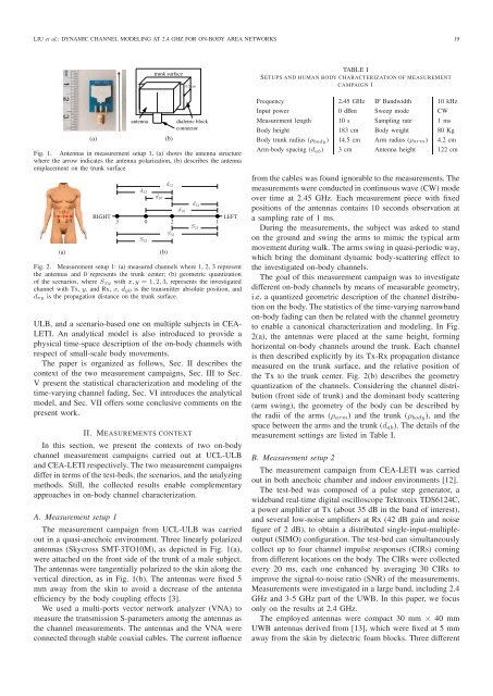
Fig. 1. Antennas in measurement setup 1, (a) shows the antenna structure<br />
where the arrow indicates the antenna polarization, (b) describes the antenna<br />
emplacement on the trunk surface<br />
(a)<br />
RIGHT<br />
3<br />
d 23<br />
d 13<br />
0<br />
d 20<br />
S 32<br />
S 31<br />
S 21<br />
(b)<br />
2<br />
d 10<br />
d 12<br />
1<br />
LEFT<br />
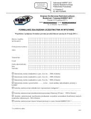
Fig. 2. Measurement setup 1: (a) measured channels where 1, 2, 3 represent<br />
the antennas and 0 represents the trunk center; (b) geometric quantization<br />
of the scenarios, where S xy with x, y = 1, 2, 3, represents the investigated<br />
channel with Tx, y, and Rx, x, d y0 is the transmitter absolute position, and<br />
d xy is the propagation distance on the trunk surface.<br />
ULB, and a scenario-based one on multiple subjects in CEA-<br />
LETI. An analytical model is also introduced to provide a<br />
physical time-space description of the on-body channels with<br />
respect of small-scale body movements.<br />
The paper is organized as follows, Sec. II describes the<br />
context of the two measurement campaigns, Sec. III to Sec.<br />
V present the statistical characterization and modeling of the<br />
time-varying channel fading, Sec. VI introduces the analytical<br />
model, and Sec. VII offers some conclusive comments on the<br />
present work.<br />
II. MEASUREMENTS CONTEXT<br />
In this section, we present the contexts of two on-body<br />
channel measurement campaigns carried out at UCL-ULB<br />
and CEA-LETI respectively. The two measurement campaigns<br />
differ in terms of the test-beds, the scenarios, and the analyzing<br />
methods. Still, the collected results enable complementary<br />
approaches in on-body channel characterization.<br />
A. Measurement setup 1<br />
The measurement campaign from UCL-ULB was carried<br />
out in a quasi-anechoic environment. Three linearly polarized<br />
antennas (Skycross SMT-3TO10M), as depicted in Fig. 1(a),<br />
were attached on the front side of the trunk of a male subject.<br />
The antennas were tangentially polarized to the skin along the<br />
vertical direction, as in Fig. 1(b). The antennas were fixed 5<br />
mm away from the skin to avoid a decrease of the antenna<br />
efficiency by the body coupling effects [3].<br />
We used a multi-ports vector network analyzer (VNA) to<br />
measure the transmission S-parameters among the antennas as<br />
the channel measurements. The antennas and the VNA were<br />
connected through stable coaxial cables. The current influence<br />
Frequency 2.45 GHz IF Bandwidth 10 kHz<br />
Input power 0 dBm Sweep mode CW<br />
Measurement length 10 s Sampling rate 1 ms<br />
Body height 183 cm Body weight 80 Kg<br />
Body trunk radius (ρ body ) 14.5 cm Arm radius (ρ arm) 4.2 cm<br />
Arm-body spacing (d ab ) 3 cm Antenna height 122 cm<br />
from the cables was found ignorable to the measurements. The<br />
measurements were conducted in continuous wave (CW) mode<br />
over time at 2.45 GHz. Each measurement piece with fixed<br />
positions of the antennas contains 10 seconds observation at<br />
a sampling rate of 1 ms.<br />
During the measurements, the subject was asked to stand<br />
on the ground and swing the arms to mimic the typical arm<br />
movement during walk. The arms swing in quasi-periodic way,<br />
which bring the dominant dynamic body-scattering effect to<br />
the investigated on-body channels.<br />
The goal of this measurement campaign was to investigate<br />
different on-body channels by means of measurable geometry,<br />
i.e. a quantized geometric description of the channel distribution<br />
on the body. The statistics of the time-varying narrowband<br />
on-body fading can then be related with the channel geometry<br />
to enable a canonical characterization and modeling. In Fig.<br />
2(a), the antennas were placed at the same height, forming<br />
horizontal on-body channels around the trunk. Each channel<br />
is then described explicitly by its Tx-Rx propagation distance<br />
measured on the trunk surface, and the relative position of<br />
the Tx to the trunk center. Fig. 2(b) describes the geometry<br />
quantization of the channels. Considering the channel distribution<br />
(front side of trunk) and the dominant body scattering<br />
(arm swing), the geometry of the body can be described by<br />
the radii of the arms (ρ arm ) and the trunk (ρ body ), and the<br />
space between the arms and the trunk (d ab ). The details of the<br />
measurement settings are listed in Table I.<br />
B. Measurement setup 2<br />
The measurement campaign from CEA-LETI was carried<br />
out in both anechoic chamber and indoor environments [12].<br />
The test-bed was composed of a pulse step generator, a<br />
wideband real-time digital oscilloscope Tektronix TDS6124C,<br />
a power amplifier at Tx (about 35 dB in the band of interest),<br />
and several low-noise amplifiers at Rx (42 dB gain and noise<br />
figure of 2 dB), to obtain a distributed single-input-multipleoutput<br />
(SIMO) configuration. The test-bed can simultaneously<br />
collect up to four channel impulse responses (CIRs) coming<br />
from different locations on the body. The CIRs were collected<br />
every 20 ms, each one enhanced by averaging 30 CIRs to<br />
improve the signal-to-noise ratio (SNR) of the measurements.<br />
Measurements were investigated in a large band, including 2.4<br />
GHz and 3-5 GHz part of the UWB. In this paper, we focus<br />
only on the results at 2.4 GHz.<br />
The employed antennas were compact 30 mm × 40 mm<br />
UWB antennas derived from [13], which were fixed at 5 mm<br />
away from the skin by dielectric foam blocks. Three different


![1RUPDOQH \FLHFKU]H FLMD VNLH](https://img.yumpu.com/54031532/1/184x260/1rupdoqh-flhfkuh-flmd-vnlh.jpg?quality=85)