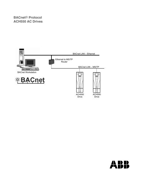
BACnet® Protocol ACH550 AC Drives
ACH550 Bacnet Protocol User's Manual - HSL Automation
ACH550 Bacnet Protocol User's Manual - HSL Automation

You also want an ePaper? Increase the reach of your titles
YUMPU automatically turns print PDFs into web optimized ePapers that Google loves.
<strong>B<strong>AC</strong>net®</strong> <strong>Protocol</strong><br />
<strong><strong>AC</strong>H550</strong> <strong>AC</strong> <strong>Drives</strong><br />
B<strong>AC</strong>net LAN – Ethernet<br />
Ethernet to MS/TP<br />
Router<br />
B<strong>AC</strong>net LAN – MS/TP<br />
B<strong>AC</strong>net Workstation<br />
<strong><strong>AC</strong>H550</strong><br />
Drive<br />
<strong><strong>AC</strong>H550</strong><br />
Drive
2 <strong><strong>AC</strong>H550</strong> B<strong>AC</strong>net User’s Manual<br />
B<strong>AC</strong>net is a registered trademark of ASHRAE.<br />
IBM is a registered trademark of International Business<br />
Machines inc.<br />
Microsoft is a registered trademark of the Microsoft<br />
Corporation.<br />
© 2004, 2005 ABB Inc. All Rights Reserved.
<strong><strong>AC</strong>H550</strong> B<strong>AC</strong>net User’s Manual 3<br />
Safety<br />
WARNING! The <strong><strong>AC</strong>H550</strong> adjustable speed <strong>AC</strong> drive should ONLY be installed<br />
by a qualified electrician.<br />
WARNING! Even when the motor is stopped, dangerous voltage is present at<br />
the Power Circuit terminals U1, V1, W1 and U2, V2, W2 and, depending on the<br />
frame size, UDC+ and UDC-, or BRK+ and BRK-.<br />
WARNING! Dangerous voltage is present when input power is connected.<br />
After disconnecting the supply, wait at least 5 minutes (to let the intermediate<br />
circuit capacitors discharge) before removing the cover.<br />
WARNING! Even when power is removed from the input terminals of the<br />
<strong><strong>AC</strong>H550</strong>, there may be dangerous voltage (from external sources) on the<br />
terminals of the relay outputs R01…R03.<br />
WARNING! When the control terminals of two or more drive units are<br />
connected in parallel, the auxiliary voltage for these control connections must<br />
be taken from a single source which can either be one of the units or an<br />
external supply.<br />
WARNING! The <strong><strong>AC</strong>H550</strong>-01/U1 is not a field repairable unit. Never attempt to<br />
repair a malfunctioning unit; contact the factory or your local Authorized<br />
Service Center for replacement.<br />
WARNING! The <strong><strong>AC</strong>H550</strong> will start up automatically after an input voltage<br />
interruption if the external run command is on.<br />
Note! For more technical information, contact the factory or your local ABB sales<br />
representative.<br />
Use of Warnings and Notes<br />
There are two types of safety instructions throughout this manual:<br />
• Notes draw attention to a particular condition or fact, or give information on a<br />
subject.<br />
• Warnings caution you about conditions which can result in serious injury or death<br />
and/or damage to the equipment. They also tell you how to avoid the danger. The<br />
warning symbols are used as follows:<br />
Dangerous voltage warning warns of high voltage which can cause physical injury<br />
and/or damage to the equipment.<br />
General warning warns about conditions, other than those caused by electricity,<br />
which can result in physical injury and/or damage to the equipment.<br />
Safety
4 <strong><strong>AC</strong>H550</strong> B<strong>AC</strong>net User’s Manual<br />
Safety
<strong><strong>AC</strong>H550</strong> B<strong>AC</strong>net User’s Manual 5<br />
Table of Contents<br />
Safety<br />
Use of Warnings and Notes . . . . . . . . . . . . . . . . . . . . . . . . . . . . . . . . . . . . . . . . 3<br />
Table of Contents<br />
Installation<br />
Introduction . . . . . . . . . . . . . . . . . . . . . . . . . . . . . . . . . . . . . . . . . . . . . . . . . . . . . 7<br />
Overview . . . . . . . . . . . . . . . . . . . . . . . . . . . . . . . . . . . . . . . . . . . . . . . . . . . . 7<br />
Control Interface . . . . . . . . . . . . . . . . . . . . . . . . . . . . . . . . . . . . . . . . . . . . . . 7<br />
Planning . . . . . . . . . . . . . . . . . . . . . . . . . . . . . . . . . . . . . . . . . . . . . . . . . . . . . . . 8<br />
Hardware Installation . . . . . . . . . . . . . . . . . . . . . . . . . . . . . . . . . . . . . . . . . . . . . 8<br />
Start-up<br />
Communications Setup . . . . . . . . . . . . . . . . . . . . . . . . . . . . . . . . . . . . . . . . . . 10<br />
Drive Parameter Group 53 . . . . . . . . . . . . . . . . . . . . . . . . . . . . . . . . . . . . . 10<br />
Quick-Start Sequence . . . . . . . . . . . . . . . . . . . . . . . . . . . . . . . . . . . . . . . . . 11<br />
Activate Drive Control Functions . . . . . . . . . . . . . . . . . . . . . . . . . . . . . . . . . . . 12<br />
Controlling the Drive . . . . . . . . . . . . . . . . . . . . . . . . . . . . . . . . . . . . . . . . . . 12<br />
Start/Stop Direction Control . . . . . . . . . . . . . . . . . . . . . . . . . . . . . . . . . . . . . 13<br />
Input Reference Select . . . . . . . . . . . . . . . . . . . . . . . . . . . . . . . . . . . . . . . . 13<br />
Miscellaneous Drive Control . . . . . . . . . . . . . . . . . . . . . . . . . . . . . . . . . . . . 13<br />
Relay Output Control . . . . . . . . . . . . . . . . . . . . . . . . . . . . . . . . . . . . . . . . . . 14<br />
Analog Output Control . . . . . . . . . . . . . . . . . . . . . . . . . . . . . . . . . . . . . . . . . 14<br />
Communication Fault . . . . . . . . . . . . . . . . . . . . . . . . . . . . . . . . . . . . . . . . . . 14<br />
Feedback from the Drive . . . . . . . . . . . . . . . . . . . . . . . . . . . . . . . . . . . . . . . . . 15<br />
Pre-defined Feedback . . . . . . . . . . . . . . . . . . . . . . . . . . . . . . . . . . . . . . . . . 15<br />
Mailbox Read/Write . . . . . . . . . . . . . . . . . . . . . . . . . . . . . . . . . . . . . . . . . . . 15<br />
Diagnostics<br />
Fault Queue for Drive Diagnostics . . . . . . . . . . . . . . . . . . . . . . . . . . . . . . . . . . 16<br />
Serial Communication Diagnostics . . . . . . . . . . . . . . . . . . . . . . . . . . . . . . . . . . 16<br />
Diagnostic Situations . . . . . . . . . . . . . . . . . . . . . . . . . . . . . . . . . . . . . . . . . . 16<br />
Technical Data<br />
<strong>Protocol</strong> Implementation Conformance Statement (PICS) . . . . . . . . . . . . . . . . 19<br />
PICS Summary . . . . . . . . . . . . . . . . . . . . . . . . . . . . . . . . . . . . . . . . . . . . . . 19<br />
Statement . . . . . . . . . . . . . . . . . . . . . . . . . . . . . . . . . . . . . . . . . . . . . . . . . . 20<br />
Object Definitions . . . . . . . . . . . . . . . . . . . . . . . . . . . . . . . . . . . . . . . . . . . . . . . 22<br />
Object/Property Support Matrix . . . . . . . . . . . . . . . . . . . . . . . . . . . . . . . . . . 22<br />
Binary Input Object Instance Summary . . . . . . . . . . . . . . . . . . . . . . . . . . . . 23<br />
Binary Output Object Instance Summary . . . . . . . . . . . . . . . . . . . . . . . . . . 23<br />
Binary Value Object Instance Summary . . . . . . . . . . . . . . . . . . . . . . . . . . . 24<br />
Analog Input Object Instance Summary . . . . . . . . . . . . . . . . . . . . . . . . . . . 26<br />
Analog Output Object Instance Summary . . . . . . . . . . . . . . . . . . . . . . . . . . 27<br />
Table of Contents
6 <strong><strong>AC</strong>H550</strong> B<strong>AC</strong>net User’s Manual<br />
Index<br />
Analog Value Object Instance Summary . . . . . . . . . . . . . . . . . . . . . . . . . . . 27<br />
Table of Contents
<strong><strong>AC</strong>H550</strong> B<strong>AC</strong>net User’s Manual 7<br />
Installation<br />
Introduction<br />
Overview<br />
The <strong><strong>AC</strong>H550</strong> can be set up to accept control from an external system using standard<br />
serial communication protocols. When using serial communication, the <strong><strong>AC</strong>H550</strong> can<br />
either:<br />
• Receive all of its control information from the fieldbus, or<br />
• Be controlled from some combination of fieldbus control and other available<br />
control locations, such as digital or analog inputs, and the control panel.<br />
Fieldbus Controller<br />
Fieldbus<br />
Other Devices<br />
Connect using either:<br />
• Standard embedded fieldbus (EFB) at<br />
terminals X1:28…32<br />
• Fieldbus adapter (FBA) module<br />
mounted in slot 2 (option Rxxx)<br />
Two basic serial communications configurations are available:<br />
• Embedded fieldbus (EFB) – Using the RS485 interface at terminals X1:28…32 on<br />
the control board, a control system can communicate through the drive’s standard<br />
EFB using standard protocols, one of which is B<strong>AC</strong>net.<br />
• Fieldbus adapter (FBA) – See the <strong><strong>AC</strong>H550</strong> User’s Manual.<br />
Control Interface<br />
In general, the basic control interface between the fieldbus system and the drive<br />
consists of:<br />
<strong>Protocol</strong> Control Interface Reference for more information<br />
B<strong>AC</strong>net • Device management<br />
• Binary output objects<br />
• Analog output objects<br />
• Binary input objects<br />
• Analog input objects<br />
"Technical Data"<br />
Installation
8 <strong><strong>AC</strong>H550</strong> B<strong>AC</strong>net User’s Manual<br />
Note! The words “output” and “input” are used as seen from the fieldbus controller<br />
point of view. For example an output describes data flow from the fieldbus controller<br />
to the drive and appears as an input from the drive point of view.<br />
Planning<br />
Network planning should address the following questions:<br />
• What types and quantities of devices must be connected to the network?<br />
• What control information must be sent down to the drives?<br />
• What feedback information must be sent from the drives to the controlling<br />
system?<br />
Hardware Installation<br />
WARNING! Connections should be made only while the drive is disconnected<br />
from the power source.<br />
Drive terminals 28…32 are for RS485 communications.<br />
• Use Belden 9842 or equivalent. Belden 9842 is a dual twisted, shielded pair cable<br />
with a wave impedance of 120 !.<br />
• Use one of these twisted shielded pairs for the RS485 link. Use this pair to<br />
connect all A (-) terminals together and all B (+) terminals together.<br />
• Use one of the wires in the other pair for the logical ground (terminal 31), leaving<br />
one wire unused.<br />
• Do not directly ground the RS485 network at any point. Ground all devices on the<br />
network using their corresponding earthing terminals.<br />
• As always, the grounding wires should not form any closed loops, and all the<br />
devices should be earthed to a common ground.<br />
• Connect the RS485 link in a daisy-chained bus, without dropout lines.<br />
• To reduce noise on the network, terminate the RS485 network using 120 !<br />
resistors at both ends of the network. Use the DIP switch to connect or disconnect<br />
the termination resistors. See following diagram and table.<br />
Terminated<br />
Terminated<br />
Station Station Station Station<br />
Installation
<strong><strong>AC</strong>H550</strong> B<strong>AC</strong>net User’s Manual 9<br />
X1 Identification Hardware Description<br />
28 Screen<br />
29 B (Positive +)<br />
30 A (Negative -)<br />
31 AGND<br />
32 Screen<br />
RS485 Multidrop application<br />
SCR<br />
+<br />
-<br />
GND<br />
SCR<br />
+<br />
-<br />
GND<br />
28 SCR<br />
29 B<br />
30 A<br />
31 AGND<br />
32 SCR<br />
RS485 interface<br />
J2<br />
ON<br />
J2<br />
ON<br />
OFF position ON position<br />
Bus termination<br />
• Connect the shield at each end of the cable to a drive. On one end, connect the<br />
shield to terminal 28, and on the other end connect to terminal 32. Do not connect<br />
the incoming and outgoing cable shields to the same terminals, as that would<br />
make the shielding continuous.<br />
• For configuration information see the following:<br />
– "Communications Setup" on page 10.<br />
– "Activate Drive Control Functions" on page 12.<br />
– "Technical Data" on page 19.<br />
Installation
10 <strong><strong>AC</strong>H550</strong> B<strong>AC</strong>net User’s Manual<br />
Start-up<br />
Communications Setup<br />
Drive Parameter Group 53<br />
Drive parameter Group 53 defines features unique to B<strong>AC</strong>net, as described below:<br />
Parameter<br />
Default<br />
Value<br />
B<strong>AC</strong>net-specific Description<br />
5301 EFB PROTOCOL ID x5xx This parameter indicates the active protocol and its<br />
revision. It should read x50xx if B<strong>AC</strong>net is properly loaded.<br />
If this is not the case, confirm that drive parameter 9802 =<br />
B<strong>AC</strong>NET (5).<br />
5302 EFB STATION ID 1 This parameter sets the drive’s B<strong>AC</strong>net MS/TP M<strong>AC</strong> ID. A<br />
temporary value of 0 places the protocol channel in reset.<br />
5303 EFB BAUD RATE 9600 This parameter sets the B<strong>AC</strong>net MS/TP baud rate.<br />
5304 EFB PARITY 0 This parameter sets the B<strong>AC</strong>net MS/TP character format<br />
as follows:<br />
0 = 8N1<br />
1 = 8N2<br />
2 = 8E1<br />
3 = 8O1.<br />
5305 EFB CTRL<br />
PROFILE<br />
5306 EFB OK<br />
MESSAGES<br />
- This parameter indicates the active control profile. This<br />
parameter has no affect on B<strong>AC</strong>net behavior.<br />
- This parameter indicates the number of valid application<br />
messages received at this drive. This count does not<br />
include MS/TP token passing and polling messages. (For<br />
such messages, see 5316.)<br />
5307 EFB CRC ERRORS - This parameter indicates the number of CRC errors<br />
detected, in either the header or data CRCs.<br />
5308 EFB UART<br />
ERRORS<br />
- This parameter indicates the number of UART-related<br />
errors (framing, parity) detected.<br />
5309 EFB STATUS - This parameter indicates the internal status of the B<strong>AC</strong>net<br />
channel as follows:<br />
• IDLE – B<strong>AC</strong>net channel is configured but not receiving<br />
messages.<br />
• TIMEOUT – Time between valid messages has<br />
exceeded the interval set by parameter 3019.<br />
• OFFLINE – B<strong>AC</strong>net channel is receiving messages<br />
NOT addressed to this drive.<br />
• ONLINE – B<strong>AC</strong>net channel is receiving messages<br />
addressed to this drive.<br />
• RESET – B<strong>AC</strong>net channel is in reset.<br />
• LISTEN ONLY – B<strong>AC</strong>net channel is in listen-only mode.<br />
5310 EFB PAR 10 5 This parameter sets the B<strong>AC</strong>net MS/TP response turnaround<br />
time, in milliseconds.<br />
Start-up
<strong><strong>AC</strong>H550</strong> B<strong>AC</strong>net User’s Manual 11<br />
5311 EFB PAR 11 0 This parameter, together with parameter 5317, EFB PAR 17,<br />
sets B<strong>AC</strong>net instance IDs:<br />
• For the range 1 to 65,535: This parameter sets the ID<br />
directly (5317 must be 0). For example, the following<br />
values set the ID to 49134: 5311 = 49134 and 5317 = 0.<br />
• For IDs > 65,335: The ID equals 5311’s value plus<br />
10,000 times 5317’s value. For example, the following<br />
values set the ID to 71234: 5311 = 1234 and 5317 = 7.<br />
5312 EFB PAR 12 1 This parameter sets the B<strong>AC</strong>net Device Object Max Info<br />
Frames property.<br />
5313 EFB PAR 13 127 This parameter sets the B<strong>AC</strong>net Device Object Max<br />
Master property.<br />
5314 EFB PAR 14 0 This parameter enables autobaud detection.<br />
0 = DISABLE<br />
1 = ENABLE<br />
5315 EFB PAR 15 When autobaud detection is enabled, this parameter<br />
displays the detected baud rate.<br />
5316 EFB PAR 16 0 This parameter indicates the count of MS/TP tokens<br />
passed to this drive.<br />
5317 EFB PAR 17 0 This parameter works with parameter 5311 to set B<strong>AC</strong>net<br />
instance IDs. See parameter 5311.<br />
5318<br />
…<br />
5320<br />
Parameter<br />
EFB PAR 18…20<br />
Changes made to drive parameter Group 53, EFB <strong>Protocol</strong>, do not take affect until<br />
you perform one of the following:<br />
• Cycle the drive power OFF and ON, or<br />
• Set parameter 5302 to 0, and then back to a unique M<strong>AC</strong> ID, or<br />
• Use the ReinitializeDevice service.<br />
Quick-Start Sequence<br />
Default<br />
Value<br />
B<strong>AC</strong>net-specific Description<br />
N/A - Not supported with B<strong>AC</strong>net protocol.<br />
The following steps summarize the process for enabling and configuring B<strong>AC</strong>net on<br />
the <strong><strong>AC</strong>H550</strong>:<br />
1. Enable B<strong>AC</strong>net protocol: Set drive parameter 9802, COMM PROTOCOL SEL = B<strong>AC</strong>NET<br />
(5).<br />
Note! If you cannot see the desired selection on the panel, your drive does not have<br />
that protocol software in the application memory.<br />
• To confirm this selection, read drive parameter 5301, EFB PROTOCOL ID. It should<br />
read x5xx (where “x” is any value).<br />
Start-up
12 <strong><strong>AC</strong>H550</strong> B<strong>AC</strong>net User’s Manual<br />
2. Place the B<strong>AC</strong>net channel in “reset”: Set drive parameter 5302, EFB STATION ID = 0.<br />
• This setting holds the B<strong>AC</strong>net communication channel in reset while remaining<br />
settings are completed.<br />
3. Define the MS/TP baud rate.<br />
• If MS/TP baud rate is known: Set drive parameter 5303, EFB BAUD RATE =<br />
appropriate value.<br />
• If MS/TP baud rate is unknown: Set drive parameter 5314, EFB PAR 14 = 1 to<br />
enable autobaud detection.<br />
4. Define the Device Object instance.<br />
• To define a specific device object instance value, use drive parameters 5311 and<br />
5317 (object instance values must be unique and in the range 1 to 4,194,303).<br />
• To use the drive’s MS/TP M<strong>AC</strong> ID as the device object instance value, set drive<br />
parameter 5311 and 5317 = 0.<br />
5. Define a unique MS/TP M<strong>AC</strong> ID. Set drive parameter 5302, EFB STATION ID =<br />
appropriate value.<br />
• Once this parameter is set to a non-zero value, current B<strong>AC</strong>net settings are<br />
“latched” and used for communication until the channel is reset.<br />
• In order to participate in MS/TP token passing, the M<strong>AC</strong> ID used must be within<br />
the limits defined by other masters’ “Max Master” property.<br />
6. Confirm proper B<strong>AC</strong>net communication.<br />
• When B<strong>AC</strong>net communication is operating properly, drive parameter 5316, EFB<br />
PAR 16 (the MS/TP token counter), should be continually increasing.<br />
• Drive parameter 5306, UART ERRORS, should be stable. (With autobaud detection,<br />
this parameter may increase until the proper baud rate is detected.)<br />
• With autobaud detection, once the proper baud rate is detected, drive parameter<br />
5315 EFB PAR 15, shows the active baud rate.<br />
Activate Drive Control Functions<br />
Controlling the Drive<br />
Fieldbus control of various drive functions requires configuration to:<br />
• Tell the drive to accept fieldbus control of the function.<br />
• Define as a fieldbus input, any drive data required for control.<br />
• Define as a fieldbus output, any control data required by the drive.<br />
The following sections describe the configuration required for each control function.<br />
Start-up
<strong><strong>AC</strong>H550</strong> B<strong>AC</strong>net User’s Manual 13<br />
Start/Stop Direction Control<br />
Using the fieldbus for start/stop/direction control of the drive requires:<br />
• Drive parameter values set as defined below.<br />
• Fieldbus controller supplied command(s) in the appropriate location.<br />
Drive Parameter Value Description<br />
1001 EXT1 COMMANDS COMM (10) Start/Stop by fieldbus with Ext1 selected. BV10<br />
1002 EXT2 COMMANDS COMM (10) Start/Stop by fieldbus with Ext2 selected. BV10<br />
1003 DIRECTION REQUEST (3) Direction by fieldbus. BV11<br />
B<strong>AC</strong>net<br />
Access Point<br />
Input Reference Select<br />
Using the fieldbus to provide input references to the drive requires:<br />
• Drive parameter values set as defined below.<br />
• Fieldbus controller supplied reference word(s) in the appropriate location.<br />
Drive Parameter Value Description B<strong>AC</strong>net Access Point<br />
1102 EXT1/EXT2 SEL COMM (8) Reference set selection by fieldbus. BV13<br />
1103 REF1 SEL COMM (8) Input reference 1 by fieldbus. AV16<br />
1106 REF2 SEL COMM (8) Input reference 2 by fieldbus. AV17<br />
Miscellaneous Drive Control<br />
Using the fieldbus for miscellaneous drive control requires:<br />
• Drive parameter values set as defined below.<br />
• Fieldbus controller supplied command(s) in the appropriate location.<br />
Drive Parameter Value Description<br />
1601 RUN ENABLE COMM (7) Run enable by fieldbus. BV12<br />
1604 FAULT RESET SEL COMM (8) Fault reset by fieldbus. BV14<br />
1608 START ENABLE 1 7 (COMM) Source for start enable 1 is the fieldbus<br />
Command word.<br />
1609 START ENABLE 2 7 (COMM) Source for start enable 2 is the fieldbus<br />
Command word.<br />
B<strong>AC</strong>net Access<br />
Point<br />
BV20<br />
BV21<br />
Start-up
14 <strong><strong>AC</strong>H550</strong> B<strong>AC</strong>net User’s Manual<br />
Relay Output Control<br />
Using the fieldbus for relay output control requires:<br />
• Drive parameter values set as defined below.<br />
• Fieldbus controller supplied, binary coded, relay command(s) in the appropriate<br />
location.<br />
Drive Parameter Value Description<br />
1401 RELAY OUTPUT 1 COMM (35) Relay Output 1 controlled by fieldbus. BO0<br />
1402 RELAY OUTPUT 2 COMM (35) Relay Output 2 controlled by fieldbus. BO1<br />
1403 RELAY OUTPUT 3 COMM (35) Relay Output 3 controlled by fieldbus. BO2<br />
1410 1 RELAY OUTPUT 4 COMM (35) Relay Output 4 controlled by fieldbus. BO3<br />
1411 1 RELAY OUTPUT 5 COMM (35) Relay Output 5 controlled by fieldbus. BO4<br />
1412 1 RELAY OUTPUT 6 COMM (35) Relay Output 6 controlled by fieldbus. BO5<br />
B<strong>AC</strong>net<br />
Access Point<br />
1. More than 3 relays requires the addition of a relay extension module.<br />
Note! Relay status feedback occurs without configuration as defined below.<br />
Drive Parameter Value B<strong>AC</strong>net Access Point<br />
0122 RO 1-3 STATUS Relay 1…3 status. BI0, BI1, BI2<br />
0123 RO 4-6 STATUS Relay 4…6 status. BI3, BI4, BI5<br />
Analog Output Control<br />
Using the fieldbus for analog output control requires:<br />
• Drive parameter values set as defined below.<br />
• Fieldbus controller supplied analog value(s) in the appropriate location.<br />
Drive Parameter Value Description<br />
1501 AO1 CONTENT SEL 135 (COMM VALUE 1) Analog Output 1 controlled by –<br />
0135 COMM VALUE 1 –<br />
writing to parameter 0135.<br />
AO0<br />
1507 AO2 CONTENT SEL 136 (COMM VALUE 2) Analog Output 2 controlled by –<br />
0136 COMM VALUE 2 –<br />
writing to parameter 0136.<br />
AO1<br />
B<strong>AC</strong>net<br />
Access Point<br />
Communication Fault<br />
When using fieldbus control, specify the drive’s action if serial communication is lost.<br />
Drive Parameter Value Description<br />
3018 COMM FAULT FUNC 0 (NOT SEL)<br />
1 (FAULT)<br />
2 (CONST SP7)<br />
3 (LAST SPEED)<br />
Set for appropriate drive response.<br />
3019 COMM FAULT TIME Set time delay before acting on a communication loss.<br />
Start-up
<strong><strong>AC</strong>H550</strong> B<strong>AC</strong>net User’s Manual 15<br />
Feedback from the Drive<br />
Pre-defined Feedback<br />
Inputs to the controller (drive outputs) have pre-defined meanings established by the<br />
protocol. This feedback does not require drive configuration. The following table lists<br />
a sample of feedback data. For a complete listing, see input word/point/object<br />
listings in the "Technical Data" section.<br />
Drive Parameter<br />
0102 SPEED AV0<br />
0103 FREQ OUTPUT AV1<br />
0104 CURRENT AV4<br />
0105 TORQUE AV5<br />
0106 POWER AV6<br />
0107 DC BUS VOLT AV2<br />
0109 OUTPUT VOLTAGE AV3<br />
0115 KWH COUNTER AV8<br />
0118 DI1-3 STATUS BI6, BI7, BI8<br />
0122 RO1-3 STATUS BI0, BI1, BI2<br />
B<strong>AC</strong>net Access Point<br />
Mailbox Read/Write<br />
The <strong><strong>AC</strong>H550</strong> provides a “Mailbox” function to access parameters that have not been<br />
pre-defined by the protocol. Using mailbox, any drive parameter can be identified<br />
and read. Mailbox can also be used to adjust parameter settings by writing a value to<br />
any parameter identified. The following table describes the use of this function.<br />
Drive Parameter<br />
Mailbox Parameter Enter the number of the drive parameter to access. AV25<br />
Mailbox Data<br />
Mailbox Read<br />
Mailbox Write<br />
Contains the parameter value after a read, or enter the<br />
desired parameter value for a write.<br />
A binary value triggers a read – the value of the “Mailbox<br />
Parameter” appears in “Mailbox data”.<br />
A binary value triggers a write – the drive value for the<br />
“Mailbox Parameter” changes to the value in “Mailbox<br />
data”.<br />
B<strong>AC</strong>net Access<br />
Point<br />
AV26<br />
BV15<br />
BV16<br />
Note! You must read and write mailbox values using the drive’s internal scaling. For<br />
example, the parameter 2202, <strong>AC</strong>CEL TIME1, has a resolution of 0.1 sec., which<br />
means that, in the drive (and in the mailbox), the value 1 = 0.1 seconds. So, a<br />
mailbox value of 10 translates to 1.0 second, a mailbox value of 300 translates to<br />
30.0 seconds, etc. Refer to the parameter listing in the <strong><strong>AC</strong>H550</strong> User’s Manual for<br />
each parameter’s resolution and units of measure.<br />
Start-up
16 <strong><strong>AC</strong>H550</strong> B<strong>AC</strong>net User’s Manual<br />
Diagnostics<br />
Fault Queue for Drive Diagnostics<br />
For general <strong><strong>AC</strong>H550</strong> diagnostics information, see “Diagnostics” in the <strong><strong>AC</strong>H550</strong><br />
User’s Manual. The three most recent <strong><strong>AC</strong>H550</strong> faults are reported to the fieldbus as<br />
defined below.<br />
Drive Parameter<br />
0401 Last Fault AV18<br />
0412 Previous Fault 1 AV19<br />
0413 Previous Fault 2 AV20<br />
B<strong>AC</strong>net Access Point<br />
Serial Communication Diagnostics<br />
Network problems can be caused by multiple sources. Some of these sources are:<br />
• Loose connections<br />
• Incorrect wiring (including swapped wires)<br />
• Incorrect baud rate<br />
• Bad grounding<br />
• Duplicate station numbers<br />
• Incorrect setup of drives or other devices on the network<br />
The major diagnostic features for fault tracing on an EFB network include Group 53<br />
EFB <strong>Protocol</strong> parameters 5306…5309. The “Parameter Descriptions” section, in the<br />
<strong><strong>AC</strong>H550</strong> User’s Manual, describes these parameters in detail.<br />
Diagnostic Situations<br />
The sub-sections below describe various diagnostic situations – the problem<br />
symptoms and corrective actions.<br />
Normal Operation<br />
During normal network operation, 5306…5309 parameter values act as follows at<br />
each drive:<br />
• 5306 EFB OK MESSAGES advances (advances for each application message<br />
properly received and addressed to this drive).<br />
• 5307 EFB CRC ERRORS does not advance at all (advances when an invalid<br />
message CRC is received).<br />
• 5308 EFB UART ERRORS does not advance at all (advances when character format<br />
errors are detected, such as parity or framing errors).<br />
• 5309 EFB status value varies depending on network traffic.<br />
Diagnostics
<strong><strong>AC</strong>H550</strong> B<strong>AC</strong>net User’s Manual 17<br />
• 5316 EFB PAR 16 (MS/TP token counter) advances for each token passed to this<br />
drive.<br />
Loss of Communication<br />
The <strong><strong>AC</strong>H550</strong> behavior, if communication is lost, was configured earlier in<br />
"Communication Fault" on page 14. The parameters are 3018 COMM FAULT FUNC and<br />
3019 COMM FAULT TIME. The “Parameter Descriptions” section in the <strong><strong>AC</strong>H550</strong> User’s<br />
Manual describes these parameters in detail.<br />
No Master Station on Line<br />
If no master station is on line: Neither 5306, EFB OK MESSAGES, nor the errors (5307<br />
EFB CRC ERRORS and 5308 EFB UART ERRORS) increase on any of the stations.<br />
To correct:<br />
• Check that a network master is connected and properly programmed on the<br />
network.<br />
• Verify that the cable is connected, and is not cut or short circuited.<br />
Duplicate Stations<br />
If two or more stations have duplicate numbers:<br />
• Two or more drives cannot be addressed.<br />
• Every time there is a read or write to one particular station, the value for 5307 EFB<br />
CRC ERRORS or 5308 EFB UART ERRORS advances.<br />
To correct: Check all station numbers and edit conflicting values.<br />
Swapped Wires<br />
If the communication wires are swapped (terminal A on one drive is connected to<br />
terminal B on another):<br />
• The value of 5306 EFB OK MESSAGES does not advance.<br />
• The values of 5307 EFB CRC ERRORS and 5308 EFB UART ERRORS are advancing.<br />
To correct: Check that the RS-485 lines are not swapped.<br />
Fault 28 – Serial 1 Err<br />
If the drive’s control panel shows fault code 28 “SERIAL 1 ERR”, check for either of the<br />
following:<br />
• The master system is down. To correct, resolve problem with master system.<br />
• The communication connection is bad. To correct, check communication<br />
connection at the drive.<br />
• The time-out selection for the drive is too short for the given installation. The<br />
master is not polling the drive within the specified time-out delay. To correct,<br />
increase the time set by parameter 3019 COMM FAULT TIME.<br />
Fault 31 – EFB1<br />
If the drive’s control panel shows fault code 31 “EFB1”, the drive has an invalid object<br />
instance ID. To correct, use parameters 5311 and 5317 and establish a unique drive<br />
ID that is in the range 1 to 4,194,303.<br />
Diagnostics
18 <strong><strong>AC</strong>H550</strong> B<strong>AC</strong>net User’s Manual<br />
Faults 32…33 – EFB2…EFB3<br />
Two EFB fault codes (fault codes 32…33) listed for the drive in the “Diagnostics”<br />
section of the <strong><strong>AC</strong>H550</strong> User’s Manual are not used.<br />
Incorrect Baud Rate<br />
If the baud rate setting does not match the network’s rate, the value of 5308, EFB<br />
UART ERRORS, increases and the value of 5306, EFB OK MESSAGES, remains fixed.<br />
If uncertain of the segment baud rate, use the autobaud detection mode, as<br />
described in "Communications Setup".<br />
Intermittent Off-line Occurrences<br />
The problems described above are the most common problems encountered with<br />
<strong><strong>AC</strong>H550</strong> serial communication. Intermittent problems might also be caused by:<br />
• Marginally loose connections.<br />
• Wear on wires caused by equipment vibrations.<br />
• Insufficient grounding and shielding on both the devices and on the<br />
communication cables.<br />
• Missing network terminations (stations at both ends of a network require<br />
termination resistors).<br />
Diagnostics
<strong><strong>AC</strong>H550</strong> B<strong>AC</strong>net User’s Manual 19<br />
Technical Data<br />
<strong>Protocol</strong> Implementation Conformance Statement (PICS)<br />
PICS Summary<br />
B<strong>AC</strong>net Standard Device Profile<br />
This version of <strong><strong>AC</strong>H550</strong> B<strong>AC</strong>net fully conforms to the 'Application-Specific<br />
Controller' standard device profile (B-ASC).<br />
Services Supported<br />
The following services are supported by the <strong><strong>AC</strong>H550</strong>:<br />
• I-Am (Response to Who-Is, also broadcast on power-up & other reset)<br />
• I-Have (Response to Who-Has)<br />
• ReadProperty<br />
• WriteProperty<br />
• DeviceCommunicationControl<br />
• ReinitializeDevice<br />
Data Link Layer<br />
The <strong><strong>AC</strong>H550</strong> implements MS/TP (Master) Data Link Layer. All standard MS/TP baud<br />
rates are supported (9600, 19200, 38400 & 76800).<br />
M<strong>AC</strong> ID / Device Object Instance<br />
The <strong><strong>AC</strong>H550</strong> supports separate M<strong>AC</strong> ID and Device Object Instance parameters:<br />
• Set the M<strong>AC</strong> ID using drive parameter 5302. Default: 5302 = 1.<br />
• Set the Device Object Instance using drive parameters 5311 and 5317. Default:<br />
Both 5311 and 5317 = 0, which causes the M<strong>AC</strong> ID to “double” as the Device<br />
Object Instance. For Device Object Instance values not linked to the M<strong>AC</strong> ID, set<br />
ID values using 5311 and 5317:<br />
– For IDs in the range 1 to 65,535: Parameter 5311sets the ID directly (5317<br />
must be 0). For example, the following values set the ID to 49,134:<br />
5311 = 49134 and 5317 = 0.<br />
– For IDs > 65,335: The ID equals 5311’s value plus 10,000 times 5317’s value.<br />
For example, the following values set the ID to 71,234:<br />
5311 = 1234 and 5317 = 7.<br />
Automatic Baud Rate Detection<br />
Set the communication baud rate using drive parameter 5303. However, this value is<br />
“overridden” if automatic baud rate detection is enabled and a different baud rate is<br />
detected. By default, autobaud detection is disabled – enable by setting drive<br />
Technical Data
20 <strong><strong>AC</strong>H550</strong> B<strong>AC</strong>net User’s Manual<br />
parameter 5314 to 1. When autobaud detection is enabled, drive parameter 5315<br />
displays the detected baud rate.<br />
Note! Autobaud detection samples for, and adjusts to, only the standard MS/TP<br />
baud rates (9600, 19200, 38400 & 76800).<br />
Max Info Frames Property<br />
Configure the Device Object Max Info Frames property using drive parameter 5312.<br />
Default: 5312 = 1.<br />
Max Master Property<br />
Configure the Device Object Max Master property using drive parameter 5313.<br />
Default: 5313 = 127.<br />
MS/TP Token Counter<br />
Parameter 5316 stores the count of MS/TP tokens passed to the associated node.<br />
Statement<br />
This statement is part of this Standard and is required for its use.<br />
B<strong>AC</strong>net <strong>Protocol</strong> Implementation Conformance Statement<br />
Date: June 1, 2005<br />
Vendor Name:<br />
Product Name:<br />
Product Model Number:<br />
ABB, Inc.<br />
Low Voltage <strong>AC</strong> Motor Drive<br />
<strong><strong>AC</strong>H550</strong><br />
Applications Software Version: 0503<br />
Firmware Revision:<br />
B<strong>AC</strong>net <strong>Protocol</strong> Revision: 2<br />
Product Description:<br />
B<strong>AC</strong>net Standardized Device Profile<br />
(Annex L):<br />
List all B<strong>AC</strong>net Interoperability Building<br />
Blocks Supported (Annex K):<br />
Segmentation Capability:<br />
206B<br />
The <strong><strong>AC</strong>H550</strong> is a high-performance adjustable frequency drive<br />
specifically designed for commercial automation applications. This<br />
product supports native B<strong>AC</strong>net, connecting directly to the MS/TP LAN.<br />
All standard MS/TP baud rates are supported, as well as master mode<br />
functionality. Over B<strong>AC</strong>net, the drive can be fully controlled as a standard<br />
adjustable frequency drive. In addition, up to 16 configurable I/O ports<br />
are available over B<strong>AC</strong>net for user applications.<br />
! B<strong>AC</strong>net Operator Workstation (B-OWS)<br />
! B<strong>AC</strong>net Building Controller (B-BC)<br />
! B<strong>AC</strong>net Advanced Application Controller (B-A<strong>AC</strong>)<br />
" B<strong>AC</strong>net Application Specific Controller (B-ASC)<br />
! B<strong>AC</strong>net Smart Sensor (B-SS)<br />
! B<strong>AC</strong>net Smart Actuator (B-SA)<br />
DS-RP-B, DS-WP-B, DM-DDB-B, DM-DOB-B, DM-DCC-B, DM-RD-B.<br />
! Segmented requests supported. Window Size ____<br />
! Segmented responses supported. Window Size ____<br />
Technical Data
<strong><strong>AC</strong>H550</strong> B<strong>AC</strong>net User’s Manual 21<br />
Standard Object Types Supported:<br />
An object type is supported if it may be<br />
present in the device. For each standard<br />
Object Type supported provide the following<br />
data:<br />
1) Whether objects of this type are<br />
dynamically creatable using the<br />
CreateObject service<br />
2) Whether objects of this type are<br />
dynamically detectable using the<br />
DeleteObject service<br />
3) List of the optional properties supported<br />
4) List of all properties that are writable<br />
where not otherwise required by this<br />
standard<br />
5) List of proprietary properties and for each<br />
its property identifier, data type, and<br />
meaning<br />
6) List of any property range restrictions<br />
Data Link Layer Options:<br />
Device Address Binding:<br />
Is static device binding supported? (This is<br />
currently necessary for two-way<br />
communication with MS/TP slaves and<br />
certain other devices.)<br />
Networking Options:<br />
Does the BBMD support registrations by<br />
Foreign Devices?<br />
Character Sets Supported:<br />
Indicating support for multiple character sets<br />
does not imply that they can all be supported<br />
simultaneously.<br />
If this product is a communication<br />
gateway, describe the types of non-<br />
B<strong>AC</strong>net equipment/network(s) that the<br />
gateway supports:<br />
B<strong>AC</strong>net <strong>Protocol</strong> Implementation Conformance Statement<br />
See table at "Object/Property Support Matrix" on page 22.<br />
! B<strong>AC</strong>net IP, (Annex J)<br />
! B<strong>AC</strong>net IP, (Annex J), Foreign Device<br />
! ISO 8802-3, Ethernet (Clause 7)<br />
! ANSI/ATA 878.1, 2.5 Mb. ARCNET (Clause 8)<br />
! ANSI/ATA 878.1, RS-485 ARCNET (Clause 8), baud rate(s) ___<br />
" MS/TP master (Clause 9), baud rate(s): 9600, 19200, 38400, 76800<br />
! MS/TP slave (Clause 9), baud rate(s): ___<br />
! Point-To-Point, EIA 232 (Clause 10), baud rate(s): ___<br />
! Point-To-Point, modem, (Clause 10), baud rate(s): ___<br />
! LonTalk, (Clause 11), medium: __________<br />
! Other: __________<br />
! Yes<br />
" No<br />
! Router, Clause 6 - List all routing configurations,<br />
e.g., ARCNET-Ethernet, Ethernet-MS/TP, etc.<br />
! Annex H, B<strong>AC</strong>net Tunneling Router over IP<br />
! B<strong>AC</strong>net/IP Broadcast Management Device (BBMD)<br />
! Yes<br />
! No<br />
" ANSI X3.4<br />
! IBM/Microsoft DBCS<br />
! ISO 8859-1<br />
! ISO 10646 (UCS-2)<br />
! ISO 10646 (UCS-4)<br />
! JIS C 6226<br />
Technical Data
22 <strong><strong>AC</strong>H550</strong> B<strong>AC</strong>net User’s Manual<br />
Object Definitions<br />
Object/Property Support Matrix<br />
The following table summarizes the Object Types/Properties Supported:<br />
Property<br />
* For commandable values only.<br />
Device<br />
Binary<br />
Input<br />
Binary<br />
Output<br />
Object Type<br />
Binary<br />
Value<br />
Analog<br />
Input<br />
Analog<br />
Output<br />
Object Identifier # # # # # # #<br />
Object Name # # # # # # #<br />
Object Type # # # # # # #<br />
System Status #<br />
Vendor Name #<br />
Vendor Identifier #<br />
Model Name #<br />
Firmware Revision #<br />
Appl Software Revision #<br />
<strong>Protocol</strong> Version #<br />
<strong>Protocol</strong> Revision #<br />
Services Supported #<br />
Object Types Supported #<br />
Object List #<br />
Max APDU Length #<br />
Segmentation Support #<br />
APDU Timeout #<br />
Number APDU Retries #<br />
Max Master #<br />
Max Info Frames #<br />
Device Address Binding #<br />
Database Revision #<br />
Present Value # # # # # #<br />
Status Flags # # # # # #<br />
Event State # # # # # #<br />
Out-of-Service # # # # # #<br />
Units # # #<br />
Priority Array # # * # # *<br />
Relinquish Default # # * # # *<br />
Polarity # #<br />
Active Text # # #<br />
Inactive Text # # #<br />
Analog<br />
Value<br />
Technical Data
<strong><strong>AC</strong>H550</strong> B<strong>AC</strong>net User’s Manual 23<br />
Binary Input Object Instance Summary<br />
The following table summarizes the Binary Input Objects supported:<br />
Instance<br />
ID<br />
Object<br />
Name<br />
Description<br />
BI0 RO 1 <strong>AC</strong>T This object indicates the status of Relay<br />
Output 1.<br />
BI1 RO 2 <strong>AC</strong>T This object indicates the status of Relay<br />
Output 2.<br />
BI2 RO 3 <strong>AC</strong>T This object indicates the status of Relay<br />
Output 3.<br />
BI3 RO 4 <strong>AC</strong>T This object indicates the status of Relay<br />
Output 4 (requires OREL-01 option).<br />
BI4 RO 5 <strong>AC</strong>T This object indicates the status of Relay<br />
Output 5 (requires OREL-01 option)<br />
BI5 RO 6 <strong>AC</strong>T This object indicates the status of Relay<br />
Output 6 (requires OREL-01 option)<br />
BI6 DI 1 <strong>AC</strong>T This object indicates the status of Digital<br />
Input 1.<br />
BI7 DI 2 <strong>AC</strong>T This object indicates the status of Digital<br />
Input 2.<br />
BI8 DI 3 <strong>AC</strong>T This object indicates the status of Digital<br />
Input 3.<br />
BI9 DI 4 <strong>AC</strong>T This object indicates the status of Digital<br />
Input 4.<br />
BI10 DI 5 <strong>AC</strong>T This object indicates the status of Digital<br />
Input 5.<br />
BI11 DI 6 <strong>AC</strong>T This object indicates the status of Digital<br />
Input 6.<br />
Active/<br />
Inactive Text<br />
ON/OFF<br />
ON/OFF<br />
ON/OFF<br />
ON/OFF<br />
ON/OFF<br />
ON/OFF<br />
ON/OFF<br />
ON/OFF<br />
ON/OFF<br />
ON/OFF<br />
ON/OFF<br />
ON/OFF<br />
Present Value<br />
Access Type<br />
R<br />
R<br />
R<br />
R<br />
R<br />
R<br />
R<br />
R<br />
R<br />
R<br />
R<br />
R<br />
Note! For Present Value Access Types, R = Read-only, W = Writeable,<br />
C = Commandable. Commandable values support priority arrays & relinquish<br />
defaults.<br />
Binary Output Object Instance Summary<br />
The following table summarizes the Binary Output Objects supported:<br />
Instance<br />
ID<br />
Object Name<br />
Description<br />
BO0 RO1 COMMAND This object controls the output state<br />
of Relay 1. This control requires<br />
that parameter 1401 value = COMM.<br />
BO1 RO2 COMMAND This object controls the output state<br />
of Relay 2. This control requires<br />
that parameter 1402 value = COMM.<br />
BO2 RO3 COMMAND This object controls the output state<br />
of Relay 3. This control requires<br />
that parameter 1403 value = COMM.<br />
Active/<br />
Inactive Text<br />
ON/OFF<br />
ON/OFF<br />
ON/OFF<br />
Present Value<br />
Access Type<br />
C<br />
C<br />
C<br />
Technical Data
24 <strong><strong>AC</strong>H550</strong> B<strong>AC</strong>net User’s Manual<br />
Instance<br />
ID<br />
Object Name<br />
Description<br />
BO3 RO4 COMMAND This object controls the output state<br />
of Relay 4. This control requires<br />
that parameter 1410 value = COMM<br />
(also requires OREL-01 option).<br />
BO4 RO5 COMMAND This object controls the output state<br />
of Relay 5. This control requires<br />
that parameter 1411 value = COMM<br />
(also requires OREL-01 option).<br />
BO5 RO6 COMMAND This object controls the output state<br />
of Relay 6. This control requires<br />
that parameter 1412 value = COMM<br />
(also requires OREL-01 option).<br />
Active/<br />
Inactive Text<br />
ON/OFF<br />
ON/OFF<br />
ON/OFF<br />
Present Value<br />
Access Type<br />
C<br />
C<br />
C<br />
Note! For Present Value Access Types, R = Read-only, W = Writeable,<br />
C = Commandable. Commandable values support priority arrays & relinquish<br />
defaults.<br />
Binary Value Object Instance Summary<br />
The following table summarizes the Binary Value Objects supported:<br />
Instance<br />
ID<br />
Object Name<br />
Description<br />
BV0 RUN/STOP <strong>AC</strong>T This object indicates the drive<br />
Run Status, regardless of the<br />
control source.<br />
BV1 FWD/REV <strong>AC</strong>T This object indicates the<br />
motor’s rotation direction,<br />
regardless of the control<br />
source.<br />
BV2 FAULT <strong>AC</strong>T this object indicates the<br />
drive’s fault status.<br />
BV3 EXT 1/2 <strong>AC</strong>T This object indicates which<br />
control source is active:<br />
External 1 or External 2.<br />
BV4 HAND/AUTO <strong>AC</strong>T This object indicates whether<br />
the drive is under Hand or<br />
Auto control.<br />
BV5 ALARM <strong>AC</strong>T This object indicates the<br />
drive’s alarm status.<br />
BV6 MAINT REQ This object indicates the<br />
drive’s maintenance status.<br />
Refer to Group 29 in the<br />
drive’s parameter<br />
descriptions.<br />
BV7 DRIVE READY This object indicates whether<br />
the drive is ready to accept a<br />
run command.<br />
BV8 AT SETPOINT This object indicates whether<br />
the drive is at the<br />
commanded setpoint.<br />
Active/Inactive<br />
Text<br />
RUN/STOP<br />
REV/FWD<br />
FAULT/OK<br />
EXT2/EXT1<br />
HAND/AUTO<br />
ALARM/OK<br />
MAINT/OK<br />
READY/NOT<br />
READY<br />
YES/NO<br />
Present Value<br />
Access Type<br />
R<br />
R<br />
R<br />
R<br />
R<br />
R<br />
R<br />
R<br />
R<br />
Technical Data
<strong><strong>AC</strong>H550</strong> B<strong>AC</strong>net User’s Manual 25<br />
Instance<br />
ID<br />
BV9 RUN ENA <strong>AC</strong>T This object indicates the Run<br />
Enable command status,<br />
regardless of the control<br />
source.<br />
BV10 RUN/STOP CMD This object commands a drive<br />
start. Control requires either:<br />
• Parameter 1001 value =<br />
COMM for control by EXT1<br />
or<br />
• Parameter 1002 value =<br />
COMM for control by EXT2.<br />
BV11 FWD/REV CMD This object commands a<br />
motor rotation direction<br />
change. Control requires<br />
1003 = REQUEST and either:<br />
• Parameter 1001 value =<br />
COMM for control by EXT1<br />
or<br />
• Parameter 1002 value =<br />
COMM for control by EXT2.<br />
BV12 RUN ENA CMD This object commands Run<br />
Enable. Control requires<br />
parameter 1601 value =<br />
COMM.<br />
BV13 EXT 1/2 CMD This object selects ext1 or<br />
ext2 as the active control<br />
source. Control requires<br />
parameter 1102 value =<br />
COMM.<br />
BV14 FAULT RESET This object resets a faulted<br />
drive. The command is risingedge<br />
triggered. Control<br />
requires parameter 1604<br />
value = COMM.<br />
BV15 MBOX READ This object reads a parameter<br />
(defined by AV25 MBOX<br />
PARAM) and returns it in AV26<br />
MBOX DATA.<br />
BV16 MBOX WRITE This object writes the data<br />
value specified by AV26,<br />
MBOX DATA, to a parameter<br />
(defined by AV25, MBOX<br />
PARAM).<br />
BV17 LOCK PANEL This object locks the panel<br />
and prevents parameter<br />
changes. The corresponding<br />
drive parameter is 1602.<br />
BV18<br />
Object Name<br />
CTL OVERRIDE<br />
CMD<br />
Description<br />
This object commands the<br />
drive into B<strong>AC</strong>net Control<br />
Override. In this mode,<br />
B<strong>AC</strong>net takes drive control<br />
from the normal source.<br />
However, the control panel’s<br />
HAND mode has priority over<br />
B<strong>AC</strong>net Control Override.<br />
Active/Inactive<br />
Text<br />
ENABLE/<br />
DISABLE<br />
RUN/STOP<br />
REV/FWD<br />
ENABLE/<br />
DISABLE<br />
EXT2/EXT1<br />
RESET/NO<br />
READ/RESET<br />
WRITE/RESET<br />
LOCK/UNLOCK<br />
ON/OFF<br />
Present Value<br />
Access Type<br />
R<br />
C<br />
C<br />
C<br />
C<br />
C<br />
W<br />
W<br />
W<br />
C<br />
Technical Data
26 <strong><strong>AC</strong>H550</strong> B<strong>AC</strong>net User’s Manual<br />
Instance<br />
ID<br />
BV19<br />
Object Name<br />
CTL OVERRIDE<br />
<strong>AC</strong>T<br />
Description<br />
This object indicates whether<br />
the drive is in B<strong>AC</strong>net Control<br />
Override. (See BV18.)<br />
BV20 START ENABLE 1 This object commands start<br />
enable1. Control requires<br />
parameter 1608 value =<br />
COMM.<br />
BV21 START ENABLE 2 This object commands start<br />
enable1. Control requires<br />
parameter 1609 value =<br />
COMM.<br />
Active/Inactive<br />
Text<br />
ON/OFF<br />
ENABLE/<br />
DISABLE<br />
ENABLE/<br />
DISABLE<br />
Present Value<br />
Access Type<br />
R<br />
C<br />
C<br />
Note! For Present Value Access Types, R = Read-only, W = Writeable,<br />
C = Commandable. Commandable values support priority arrays & relinquish<br />
defaults.<br />
Analog Input Object Instance Summary<br />
The following table summarizes the Analog Input Objects supported:<br />
Instance<br />
ID<br />
Object Name Description Units<br />
AI0 ANALOG INPUT 1 This object indicates the value of<br />
Analog Input 1. The corresponding<br />
drive parameter is 0120.<br />
AI1 ANALOG INPUT 2 This object indicates the value of<br />
Analog Input 2. The corresponding<br />
drive parameter is 0121.<br />
Percent<br />
Percent<br />
Present Value<br />
Access Type<br />
R<br />
R<br />
Note! For Present Value Access Types, R = Read-only, W = Writeable,<br />
C = Commandable. Commandable values support priority arrays & relinquish<br />
defaults.<br />
Technical Data
<strong><strong>AC</strong>H550</strong> B<strong>AC</strong>net User’s Manual 27<br />
Analog Output Object Instance Summary<br />
The following table summarizes the Analog Output Objects supported:<br />
Instance<br />
ID<br />
AO0 AO 1<br />
COMMAND<br />
AO1 AO 2<br />
COMMAND<br />
Object Name Description Units<br />
This object controls Analog Output 1. The<br />
corresponding drive parameter is 0135,<br />
COMM VALUE 1. Control requires parameter<br />
1501 value = 135.<br />
This object controls Analog Output 2. The<br />
corresponding drive parameter is 0136,<br />
COMM VALUE 2. Control requires parameter<br />
1507 value = 136.<br />
Percent<br />
Percent<br />
Present Value<br />
Access Type<br />
C<br />
C<br />
Note! For Present Value Access Types, R = Read-only, W = Writeable,<br />
C = Commandable. Commandable values support priority arrays & relinquish<br />
defaults.<br />
Analog Value Object Instance Summary<br />
The following table summarizes the Analog Value Objects supported:<br />
Instance<br />
ID<br />
AV0<br />
Object Name Description Units<br />
OUTPUT<br />
SPEED<br />
This object indicates the calculated motor<br />
speed in RPM. The corresponding drive<br />
parameter is 0102.<br />
AV1 OUTPUT FREQ This object indicates the output<br />
frequency applied to the motor in Hz. The<br />
corresponding drive parameter is 0103.<br />
AV2 DC BUS VOLT This object indicates the drive’s DC bus<br />
voltage level. The corresponding drive<br />
parameter is 0107.<br />
AV3 OUTPUT VOLT This object indicates the <strong>AC</strong> output<br />
voltage applied to the motor. The<br />
corresponding drive parameter is 0109.<br />
AV4 CURRENT This object indicates the measured<br />
output current. The corresponding drive<br />
parameter is 0104.<br />
AV5 TORQUE This object indicates the calculated motor<br />
output torque as a percentage of nominal<br />
torque. The corresponding drive<br />
parameter is 0105.<br />
AV6 POWER This object indicates the measured<br />
output power in kW. The corresponding<br />
drive parameter is 0106.<br />
AV7 DRIVE TEMP This object indicates the measured<br />
heatsink temperature in °C. The<br />
corresponding drive parameter is 0110.<br />
RPM<br />
Hertz<br />
Volts<br />
Volts<br />
Amps<br />
Percent<br />
Kilowatts<br />
Present Value<br />
Access Type<br />
R<br />
R<br />
R<br />
R<br />
R<br />
R<br />
R<br />
°C R<br />
Technical Data
28 <strong><strong>AC</strong>H550</strong> B<strong>AC</strong>net User’s Manual<br />
Instance<br />
ID<br />
Object Name Description Units<br />
Present Value<br />
Access Type<br />
AV8 KWH (R) This object indicates, in kW hours, the<br />
drive’s accumulated energy usage since<br />
the last reset. The value can be reset to<br />
zero. The corresponding drive parameter<br />
is 0115.<br />
AV9 KWH (NR) This object indicates the drive’s<br />
accumulated energy usage in kW hours.<br />
The value cannot be reset.<br />
AV10 PRC PID FBCK This object is the Process PID feedback<br />
signal. The corresponding drive<br />
parameter is 0130.<br />
AV11 PRC PID DEV This object is the Process PID output<br />
signal’s deviation from its setpoint. The<br />
corresponding drive parameter is 0132.<br />
AV12 EXT PID FBCK This object is the External PID feedback<br />
signal. The corresponding drive<br />
parameter is 0131.<br />
AV13 EXT PID DEV This object is the External PID output<br />
signal’s deviation from its setpoint. The<br />
corresponding drive parameter is 0133.<br />
AV14 RUN TIME (R) This object indicates, in hours, the drive’s<br />
accumulated run time since the last reset.<br />
The value can be reset to zero. The<br />
corresponding drive parameter is 0114.<br />
kWh<br />
kWh<br />
Percent<br />
Percent<br />
Percent<br />
Percent<br />
Hours<br />
W<br />
R<br />
R<br />
R<br />
R<br />
R<br />
W<br />
AV15 MOTOR TEMP This object indicates the drive’s motor<br />
temperature, as set up in parameter<br />
Group 35. The corresponding drive<br />
parameter is 0145.<br />
°C R<br />
AV16 INPUT REF 1 This object sets Input Reference 1.<br />
Control requires parameter 1103 value =<br />
COMM.<br />
AV17 INPUT REF 2 This object sets either:<br />
• Input Reference 2. Control requires<br />
parameter 1106 value = COMM.<br />
• Process PID setpoint. Control requires<br />
parameter 1106 value = PID1 OUT and<br />
parameter 4010 value = COMM.<br />
AV18 LAST FLT This object indicates the most recent fault<br />
entered in the drive’s fault log. The<br />
corresponding drive parameter is 0401.<br />
AV19 PREV FLT 1 This object indicates the second most<br />
recent fault entered in the drive’s fault<br />
log. The corresponding drive parameter<br />
is 0412.<br />
AV20 PREV FLT 2 This object indicates the third most recent<br />
fault entered in the drive’s fault log. The<br />
corresponding drive parameter is 0413.<br />
AV21 AO 1 <strong>AC</strong>T This object indicates Analog Output 1’s<br />
level. The corresponding drive parameter<br />
is 0124.<br />
Percent<br />
Percent<br />
None<br />
None<br />
None<br />
Milliamps<br />
C<br />
C<br />
R<br />
R<br />
R<br />
R<br />
Technical Data
<strong><strong>AC</strong>H550</strong> B<strong>AC</strong>net User’s Manual 29<br />
Instance<br />
ID<br />
Object Name Description Units<br />
AV22 AO 2 <strong>AC</strong>T This object indicates Analog Output 2’s<br />
level. The corresponding drive parameter<br />
is 0125.<br />
AV23 <strong>AC</strong>CEL1 TIME This object sets the Ramp1 acceleration<br />
time. The corresponding drive parameter<br />
is 2202.<br />
AV24 DECEL1 TIME This object sets the Ramp1 deceleration<br />
time. The corresponding drive parameter<br />
is 2203.<br />
AV25 MBOX PARAM This object defines the parameter to be<br />
read or written to by the mailbox function.<br />
See BV15 and BV16.<br />
AV26 MBOX DATA This object holds the mailbox function’s<br />
parameter value – a value that was read,<br />
or is to be written. See BV15 and BV16.<br />
AV27 EXT PID STPT This object sets the External PID<br />
controller setpoint. The corresponding<br />
drive parameter is 4211. Control requires<br />
parameter 4210, PID SETPOINT SEL, value<br />
= 19 (INTERNAL).<br />
Milliamps<br />
Seconds<br />
Seconds<br />
None<br />
None<br />
Percent<br />
Present Value<br />
Access Type<br />
R<br />
W<br />
W<br />
W<br />
W<br />
C<br />
Note! For Present Value Access Types, R = Read-only, W = Writeable,<br />
C = Commandable. Commandable values support priority arrays & relinquish<br />
defaults.<br />
Technical Data
30 <strong><strong>AC</strong>H550</strong> B<strong>AC</strong>net User’s Manual<br />
Index<br />
A<br />
autobaud detection . . . . . . . . . . . . . . . . . . . . . . . 19<br />
B<br />
baud rate detection . . . . . . . . . . . . . . . . . . . . . . . 19<br />
bus<br />
connections. . . . . . . . . . . . . . . . . . . . . . . . . . . 8<br />
C<br />
comm (EFB)<br />
analog output control, activate . . . . . . . . . . . 14<br />
comm fault response . . . . . . . . . . . . . . . . . . 14<br />
configuration . . . . . . . . . . . . . . . . . . . . . . . . . 10<br />
configure for loss of communication . . . . . . . 17<br />
control interface . . . . . . . . . . . . . . . . . . . . . . . 7<br />
drive control of functions, activate. . . . . . . . . 12<br />
fault code 28 . . . . . . . . . . . . . . . . . . . . . . . . . 17<br />
fault code 31 . . . . . . . . . . . . . . . . . . . . . . . . . 17<br />
fault code 32 . . . . . . . . . . . . . . . . . . . . . . . . . 18<br />
fault code 33 . . . . . . . . . . . . . . . . . . . . . . . . . 18<br />
fault tracing parameters . . . . . . . . . . . . . . . . 16<br />
fault, duplicate stations . . . . . . . . . . . . . . . . . 17<br />
fault, intermittent off-line . . . . . . . . . . . . . . . . 18<br />
fault, no master station on line . . . . . . . . . . . 17<br />
fault, swapped wires . . . . . . . . . . . . . . . . . . . 17<br />
feedback from drive . . . . . . . . . . . . . . . . . . . 15<br />
feedback from drive, mailbox . . . . . . . . . . . . 15<br />
input ref. sel., activate. . . . . . . . . . . . . . . . . . 13<br />
mailbox, param. read/write . . . . . . . . . . . . . . 15<br />
misc. drive control, activate. . . . . . . . . . . . . . 13<br />
normal operation. . . . . . . . . . . . . . . . . . . . . . 16<br />
relay output control, activate. . . . . . . . . . . . . 14<br />
setup . . . . . . . . . . . . . . . . . . . . . . . . . . . . . . . 10<br />
start/stop control, activate. . . . . . . . . . . . . . . 13<br />
termination . . . . . . . . . . . . . . . . . . . . . . . . . . . 8<br />
connections<br />
bus . . . . . . . . . . . . . . . . . . . . . . . . . . . . . . . . . 8<br />
D<br />
data link layer . . . . . . . . . . . . . . . . . . . . . . . . . . . 19<br />
diagnostics . . . . . . . . . . . . . . . . . . . . . . . . . . . . . 16<br />
drive<br />
bus connections . . . . . . . . . . . . . . . . . . . . . . . 8<br />
F<br />
fault<br />
comm failure (EFB). . . . . . . . . . . . . . . . . . . . 14<br />
fault code<br />
28 serial 1 err . . . . . . . . . . . . . . . . . . . . . . . . 17<br />
G<br />
group 53 parameters . . . . . . . . . . . . . . . . . . . . . . 27<br />
I<br />
installation. . . . . . . . . . . . . . . . . . . . . . . . . . . . . . . . 7<br />
M<br />
mac id . . . . . . . . . . . . . . . . . . . . . . . . . . . . . . . . . . 19<br />
mailbox, EFB comm . . . . . . . . . . . . . . . . . . . . . . . 15<br />
max info frame property . . . . . . . . . . . . . . . . . . . . 20<br />
N<br />
network<br />
planning . . . . . . . . . . . . . . . . . . . . . . . . . . . . . . 8<br />
O<br />
object<br />
analog inputs . . . . . . . . . . . . . . . . . . . . . . . . . 26<br />
analog outputs . . . . . . . . . . . . . . . . . . . . . . . . 27<br />
analog values . . . . . . . . . . . . . . . . . . . . . . . . . 27<br />
binary inputs. . . . . . . . . . . . . . . . . . . . . . . . . . 23<br />
binary outputs. . . . . . . . . . . . . . . . . . . . . . . . . 23<br />
binary values . . . . . . . . . . . . . . . . . . . . . . . . . 24<br />
definitions . . . . . . . . . . . . . . . . . . . . . . . . . . . . 22<br />
P<br />
pics<br />
statement . . . . . . . . . . . . . . . . . . . . . . . . . . . . 20<br />
summary . . . . . . . . . . . . . . . . . . . . . . . . . . . . 19<br />
planning . . . . . . . . . . . . . . . . . . . . . . . . . . . . . . . . . 8<br />
protocol implementation conformance statement<br />
see pics<br />
Q<br />
quick-start sequence . . . . . . . . . . . . . . . . . . . . . . 10<br />
R<br />
RS485 comm . . . . . . . . . . . . . . . . . . . . . . . . . . . . . 8<br />
S<br />
serial 1 error (fault code 28) . . . . . . . . . . . . . . . . . 17<br />
services supported . . . . . . . . . . . . . . . . . . . . . . . . 19<br />
start<br />
control, EFB comm. . . . . . . . . . . . . . . . . . . . . 13<br />
start-up . . . . . . . . . . . . . . . . . . . . . . . . . . . . . . . . . 10<br />
support<br />
matrix . . . . . . . . . . . . . . . . . . . . . . . . . . . . . . . 22<br />
T<br />
technical data . . . . . . . . . . . . . . . . . . . . . . . . . . . . 19<br />
termination . . . . . . . . . . . . . . . . . . . . . . . . . . . . . . . 8<br />
Index
3AUA0000004591 REV C / EN<br />
EFFECTIVE: OCT. 27, 2005<br />
SUPERSEDES: FEB. 7, 2005<br />
ABB Oy<br />
<strong>AC</strong> <strong>Drives</strong><br />
P.O. Box 184<br />
FIN-00381 HELSINKI<br />
FINLAND<br />
Telephone +358 10 22 11<br />
Telefax +358 10 22 22681<br />
Internet http://www.abb.com<br />
ABB Inc.<br />
Automation Technologies<br />
<strong>Drives</strong> & Machines<br />
16250 West Glendale Drive<br />
New Berlin, WI 53151<br />
USA<br />
Telephone 262 785-3200<br />
800 HELP-365<br />
Telefax 262 780-5135