AUTUMN
1SflouO
1SflouO

Create successful ePaper yourself
Turn your PDF publications into a flip-book with our unique Google optimized e-Paper software.
Metal AM part development<br />
| contents page | news | events | advertisers’ index | contact |<br />
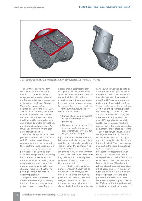
Fig. 4 Layerwise’s first build configuration of my part (Courtesy Layerwise/3D Systems)<br />
One of these people was Tom<br />
De Bruyne, General Manager at<br />
Layerwise. Layerwise is a Belgian<br />
company which was started out of<br />
the Catholic University of Leuven (one<br />
of the premier centres of Additive<br />
Manufacturing research); it was<br />
acquired by 3D Systems in late 2014.<br />
They’re famous for being one of the<br />
few service providers who built their<br />
own laser metal powder bed fusion<br />
machines, and have a ton of experience<br />
making 3D printed parts at both<br />
prototype and production scale. We<br />
struck up a conversation, and soon<br />
agreed to work together.<br />
While popular opinion would have<br />
you think that quantity is a non-factor<br />
with 3D printing, the realities of<br />
running a service bureau are much<br />
to the contrary. To job shops, quantity<br />
is a critical factor; if a part will be<br />
produced at large volumes, every<br />
detail of its design and manufacturing<br />
life cycle must be examined. If, on<br />
the other hand, you’re printing a tool<br />
or a prototype of a part that will be<br />
manufactured conventionally, most<br />
shops will focus on getting the first<br />
print right without modifying its<br />
underlying geometry.<br />
My project falls somewhere in the<br />
middle: while my design is certainly<br />
imperfect, there are many aspects<br />
of it which are very close. Moreover,<br />
it poses challenges (most notably<br />
its opposing cylinders, oriented 90°<br />
apart, and also its thin-wall construction<br />
and bolt boss) that will exist<br />
throughout any redesign, and solving<br />
them now will only improve my ability<br />
to deal with them in future iterations.<br />
At the current juncture, the key<br />
questions to test were:<br />
• Can we reliably build my current<br />
design with minimal post<br />
processing?<br />
• Does my current design meet the<br />
necessary performance standards<br />
(strength, security, etc.) for<br />
bicycle seatmast toppers?<br />
In practical terms, the first question<br />
boils down to whether we can build a<br />
part that can be installed on a bicycle.<br />
This means two things: maintaining<br />
inner diameters which are round<br />
and dimensionally accurate to within<br />
+/-.006”, and having a bolt boss on the<br />
long cylinder which, when tightened,<br />
is capable of securing the part to a<br />
bicycle’s seatmast.<br />
I worked with Martijn Vanloffelt,<br />
a project engineer at Layerwise, on<br />
the next phase of prototypes. He<br />
used a few key tricks and built my<br />
parts on a machine that Layerwise<br />
designed themselves. In order to<br />
maintain roundness in the saddle<br />
clamp cylinder (the shorter of the two<br />
cylinders, which was was going to be<br />
oriented more or less parallel to the<br />
build plate), Layerwise reinforced the<br />
inner diameter with three serrated<br />
discs (Fig. 4). They also oriented the<br />
part slightly off-axis in both the X and<br />
Y axes. This brings me to a point that’s<br />
worth highlighting: In metal powder<br />
bed fusion, a part’s orientation has<br />
a number of effects. First of all, any<br />
surface with an angle of less than<br />
about 45° (depending on material)<br />
must be supported. As a result, it’s<br />
generally better to orient a part so that<br />
all overhangs are as steep as possible.<br />
But in addition, one must consider<br />
the angle between the part and the<br />
recoater blade. If the part lifts up at<br />
any point during the build, the recoater<br />
blade will strike it. The longer the area<br />
of contact is, the worse the result will<br />
be. Some machine manufacturers<br />
offer alternative recoaters to lower<br />
this risk (3D Systems ProX uses a<br />
roller; EOS offers a carbon fibre brush;<br />
Arcam uses a metal comb; and both<br />
Concept Laser and SLM offer soft<br />
polymer blades), but most use a piece<br />
of high speed steel (or, in the case of<br />
older EOS machines, a ceramic blade)<br />
to spread powder across the build<br />
platform. Regardless, it is usually<br />
better to orient parts slightly off axis in<br />
the XY plane, so that the blade doesn’t<br />
contact the part’s walls all at once.<br />
44 Metal Additive Manufacturing | Autumn/Fall 2015<br />
© 2015 Inovar Communications Ltd Vol. 1 No. 3