Wolverine Project TAILINGS AND INFRASTRUCTURE DESIGN ...
Wolverine Project TAILINGS AND INFRASTRUCTURE DESIGN ...
Wolverine Project TAILINGS AND INFRASTRUCTURE DESIGN ...

You also want an ePaper? Increase the reach of your titles
YUMPU automatically turns print PDFs into web optimized ePapers that Google loves.
<strong>Wolverine</strong> <strong>Project</strong><br />
<strong>TAILINGS</strong> <strong>AND</strong> <strong>INFRASTRUCTURE</strong> <strong>DESIGN</strong> <strong>AND</strong><br />
CONSTRUCTION PLAN<br />
VERSION 2009-02<br />
Prepared by:<br />
Klohn Crippen Berger Ltd<br />
In Association with:<br />
Yukon Zinc Corporation<br />
March 2009
<strong>Wolverine</strong> <strong>Project</strong> Tailings and Related Infrastructure Design and Construction Plan<br />
EXECUTIVE SUMMARY<br />
Klohn Crippen Berger.M09234A04<br />
Version 2009-02<br />
This Tailings and Infrastructure Design and Construction Plan (Version 2009-02) presents the<br />
detailed design of the tailings storage facility (TSF) for the <strong>Wolverine</strong> underground zinc-silver<br />
mine located in south eastern Yukon Territory. The <strong>Wolverine</strong> <strong>Project</strong> has received Quartz<br />
Mining License QML-0006 (QML-0006) and Type A Water Licence QZ04-065 (QZ04-065) and<br />
is proceeding with detailed engineering design for all components. The bulk of construction<br />
activities are scheduled for spring 2009, and full operation of the tailings facility is scheduled for<br />
June 2010 with mill startup. For additional <strong>Wolverine</strong> <strong>Project</strong> information, refer to General Site<br />
Plan (Version 2008-04), which includes updated information on the overall project layout,<br />
project development schedule, site and underground mine development overview, and<br />
construction details for the permanent camp, and site roads.<br />
This Plan has been prepared to satisfy QML-0006 Condition 13.3. This report consolidates<br />
changes made to the TSF since the Feasibility Study and Optimized Feasibility Study were issued<br />
in 2006 and 2007, respectively, and submission of the Revised Documentation in Support of A-<br />
Licence Application QZ04-065 in January 2007.<br />
Site Conditions<br />
The project is located in gently rolling hills and mountains with elevations up to 1800 m. The<br />
TSF area is covered with small shrubs and grasses near elevation 1300 m. The TSF is formed by<br />
a 700 m long L-shaped dam, up to 23.5 m high, located in a small drainage northeast of Go<br />
Creek. The foundation soils consist of medium dense to dense ablation tills up to 15 m deep that<br />
overlie bedrock. Local shallow peat deposits occur within the basin. The area is of moderate<br />
seismicity.<br />
The mean annual precipitation and evaporation are 570 mm and 400 mm, respectively. Average<br />
snowpack is 175 mm of snow water equivalent. Mean monthly temperatures are below zero from<br />
October to April. The hydrogeologic regime consists of a shallow aquifer in the soils<br />
March 2009 Page i
<strong>Wolverine</strong> <strong>Project</strong> Tailings and Related Infrastructure Design and Construction Plan<br />
Klohn Crippen Berger.M09234A04<br />
Version 2009-02<br />
immediately above the bedrock and the estimated groundwater flow beneath the tailings basin is<br />
approximately 15 L/s.<br />
A site investigation program was carried out that consisted of 5 drill holes and 20 test pits within<br />
the TSF area, and additional drilling, testpits and geopyhysical surveys were completed in the<br />
general area. Laboratory testing consisted of index testing, shear strength determination and<br />
consolidation tests on the tailings. The dam foundation soils are not susceptible to liquefaction.<br />
Dam construction fills, to be borrowed from the interior of the impoundment, consist of<br />
competent glacial silty sands and gravels.<br />
Tailings Storage Facility Design<br />
The milling process will produce tailings, which will either be deposited in the underground<br />
mine as paste backfill, or deposited in the tailings facility. The tailings have high sulphide<br />
content and have the potential to become acid generating if allowed to oxidize. Therefore,<br />
tailings will be stored in the saturated containment system described herein.<br />
The design of the facility is based on field and laboratory investigations of the foundation<br />
conditions and considerations of geochemical characteristics of the tailings and supernatant<br />
water. The design incorporates the availability of local dam borrow materials, storage capacity<br />
requirements, site water balance, dam failure consequence rating, and earthquake and flood<br />
potential.<br />
The impoundment is designed to safely route the 1:10,000 year return period flood through<br />
spillways (Starter Spillway and Ultimate Spillway) located in the west flank of the dam. During<br />
operations the TSF will also store the 1:200 year return-period flood event, without the release of<br />
water. The design earthquake is a 1:10,000 return period, with a peak ground acceleration of<br />
0.22 g. The minimum geotechnical factors of safety during operations are 1.5 for static stability<br />
and 1.1 for pseudo-static stability. Analysis of the impoundment liner leakage rate indicates an<br />
actual seepage predicted rate of 10 -5 L/s. The negligibly low seepage rate provides a safety<br />
margin against the potential for long-term degradation of portions of the liner.<br />
March 2009 Page ii
<strong>Wolverine</strong> <strong>Project</strong> Tailings and Related Infrastructure Design and Construction Plan<br />
Klohn Crippen Berger.M09234A04<br />
Version 2009-02<br />
The tailings facility includes a L-shaped tailings dam, a tailings pond, a seepage recovery dam<br />
and pond, two upland diversion ditches, and spillways (see Drawing D-3001). The impoundment<br />
covers an area approximately 600 m long and 300 m wide. The catchment area for the TSF will<br />
be reduced with the construction of two main diversion ditches (Ditches A and B). The<br />
maximum dam height is 16.5 m and 23.5 m high at project start up and after Year 2 of mining<br />
operations, respectively.<br />
The tailings dam is a compacted homogeneous earthfill dam with an impervious geosynthetic<br />
liner. The liner will cover the base of the tailings impoundment and the upstream face of the dam<br />
up to the Ultimate Dam crest. A seepage collection pond will be constructed downstream of the<br />
main dam as a contingency to allow return of contaminated water.<br />
Construction and Operations<br />
Dam construction is scheduled to start in spring 2009, with drainage and surface preparation<br />
works having commenced in fall 2008. A QA/QC program will be carried out during<br />
construction, and as-built records will be prepared. Construction of the TSF will use best<br />
practices for control of erosion and sediment, as outlined in General Site Plan (2008-04).<br />
The TSF will be constructed in two stages, a 16.5 m high Starter Dam, which will then be raised<br />
to a 23.5 m high Ultimate Dam in 2011. The starter dam will be a homogeneous earthfill dam<br />
with a 6 m wide crest and a 2H:1V downstream slope and a 2H:1V upstream slope. The dam<br />
raise will be by the downstream method. The impoundment will be lined with a 40 mil linear<br />
low-density polyethylene (LLDPE) geomembrane liner placed on a foundation prepared by<br />
compaction with a smooth drum roller. Fine material will be placed as required to produce a<br />
suitable base.<br />
Tailings will be spigotted from the dam crest and from the upstream edge of the impoundment. A<br />
reclaim pond will initially form near the south side of the dam and in approximately Year 5<br />
tailings will be spigotted from the dam at the south end of the impoundment and the reclaim<br />
pond will be reformed towards the north end to facilitate closure. In approximately Year 6, the<br />
reclaim barge will be moved to the north end.<br />
March 2009 Page iii
<strong>Wolverine</strong> <strong>Project</strong> Tailings and Related Infrastructure Design and Construction Plan<br />
Water Management and Treatment<br />
Klohn Crippen Berger.M09234A04<br />
Version 2009-02<br />
Water within the TSF will be reclaimed to the mill. The water balance results in a net annual<br />
water surplus of approximately 4.1 m 3 /h to 7.6 m 3 /h, which will be treated prior to discharge. A<br />
pilot water treatment plant will be constructed in the first year of operations to develop the final<br />
plant design based on the actual supernatant solutions. Storage capacity is provided in the TSF<br />
for the first few years of operations to allow for pilot plant testing with actual process water to<br />
design and construct the water treatment plant.<br />
Closure Plan<br />
Reclamation and closure plans for closure of the tailings facility are documented in the approved<br />
<strong>Wolverine</strong> <strong>Project</strong> Reclamation and Closure Plan (2008-02). A revised Reclamation and Closure<br />
Plan is required by QML-0006 to be submitted in December 2009, and updated plans for closure<br />
of the tailings facility will be based on as-built drawings. In general, the dam and the closure<br />
spillway are designed as “robust” structures which will be resistant to long-term erosion forces.<br />
As per QML-0006 Condition 16.5, a minimum of 1.0 m of coarse grained material, demonstrated<br />
to not have ARD/ML potential, will be placed over the stored tailings.<br />
Additional QML-0006 Requirements<br />
An Operation, Maintenance and Surveillance (OM&S) Manual will be prepared to document<br />
best practices for TSF operations, and will be submitted in 2009 to Yukon Energy, Mines and<br />
Resources for review and approval. The preliminary Emergency Response and Preparedness<br />
Plan, provided in Appendix IV, will be updated and integrated into the OM&S Manual.<br />
March 2009 Page iv
<strong>Wolverine</strong> <strong>Project</strong> Tailings and Related Infrastructure Design and Construction Plan<br />
TABLE OF CONTENTS<br />
Version 2009-02<br />
1. INTRODUCTION ...............................................................................................................1<br />
1.1 General.....................................................................................................................1<br />
1.2 Tailings Facility Summary.......................................................................................3<br />
1.3 Report Disclaimer ....................................................................................................4<br />
2. SITE CONDITIONS............................................................................................................6<br />
2.1 Geology and Seismicity ...........................................................................................7<br />
2.1.1 Geology........................................................................................................7<br />
2.1.2 Seismicity.....................................................................................................7<br />
2.2 Hydrology and Groundwater .................................................................................10<br />
2.3 Water Quality.........................................................................................................14<br />
3. <strong>DESIGN</strong> CRITERIA .........................................................................................................15<br />
3.1 Dam Classification Assessment.............................................................................16<br />
3.1.1 Dam Break Assessment .............................................................................18<br />
3.2 Earthquake, Flood and Seepage Criteria................................................................20<br />
4. GEOTECHNICAL CHARACTERIZATION ...................................................................25<br />
4.1 Site Investigations..................................................................................................25<br />
4.2 Geotechnical Testing .............................................................................................25<br />
5. GEOCHEMICAL CHARACTERIZATION.....................................................................27<br />
5.1 Tailings Geochemistry...........................................................................................27<br />
5.2 Borrow for Dam Construction Materials ...............................................................33<br />
5.3 Supernatant Water Chemistry................................................................................33<br />
6. <strong>TAILINGS</strong> IMPOUNDMENT ..........................................................................................37<br />
6.1 Storage Capacity ....................................................................................................37<br />
6.2 Deposition Strategy and Staged Development ......................................................39<br />
6.3 Liner Design...........................................................................................................41<br />
6.4 Tailings Facility Water Balance.............................................................................43<br />
6.5 Water Quality Management...................................................................................44<br />
7. <strong>TAILINGS</strong> DAM...............................................................................................................46<br />
7.1 Geotechnical Parameters........................................................................................47<br />
Klohn Crippen Berger.M09234A04<br />
March 2009 Page v
<strong>Wolverine</strong> <strong>Project</strong> Tailings and Related Infrastructure Design and Construction Plan<br />
Klohn Crippen Berger.M09234A04<br />
Version 2009-02<br />
7.2 Slope Stability Analyses ........................................................................................48<br />
8. WATER MANAGEMENT <strong>INFRASTRUCTURE</strong> ...........................................................51<br />
8.1 Surface Water Diversion Ditches...........................................................................51<br />
8.2 Tailing Dam Spillways ..........................................................................................53<br />
8.2.1 Hydraulic Design Parameters ....................................................................53<br />
8.2.2 Spillway Construction Components ..........................................................56<br />
8.3 Seepage Collection Infrastructure..........................................................................56<br />
8.3.1 Seepage Collection Pond ...........................................................................56<br />
8.3.2 Seepage Dam Spillway ..............................................................................57<br />
9. CONSTRUCTION.............................................................................................................59<br />
9.1 Construction Plan...................................................................................................59<br />
9.1.1 Stage I Starter Dam and Impoundment (Year 2008 to 2010) ....................59<br />
9.1.2 Stage II Ultimate Dam and Impoundment (Year 2011).............................60<br />
9.1.3 Closure (Year 2019 to 2022)......................................................................61<br />
9.2 Construction Materials and Details........................................................................61<br />
9.3 Construction Methods............................................................................................63<br />
9.4 Bill of Quantities....................................................................................................65<br />
10. WATER TREATMENT PLANT ......................................................................................68<br />
10.1 High Density Sludge (HDS) Water Treatment ......................................................68<br />
10.1.1 Bench Scale Testing Results of HDS.........................................................68<br />
10.1.2 HDS Treatment Process.............................................................................69<br />
10.2 Bioreactor for Selenium Reduction .......................................................................73<br />
10.2.1 Summary of Test Results Using Biological Reduction .............................75<br />
10.2.2 Preliminary Design of the Biological Reduction System ..........................77<br />
11. CLOSURE .........................................................................................................................80<br />
11.1 Dam Safety.............................................................................................................80<br />
11.2 Geochemical Stability and Surface Water Quality ................................................81<br />
11.3 Decommissioning of Water Management Infrastructure.......................................81<br />
12. DAM SAFETY MONITORING PROGRAM ..................................................................83<br />
12.1 Dam Safety Monitoring and Instrumentation ........................................................83<br />
12.2 Adaptive Management Plan...................................................................................85<br />
March 2009 Page vi
<strong>Wolverine</strong> <strong>Project</strong> Tailings and Related Infrastructure Design and Construction Plan<br />
Klohn Crippen Berger.M09234A04<br />
Version 2009-02<br />
13. SUMMARY <strong>AND</strong> RECOMMENDATIONS....................................................................87<br />
Table 2.1<br />
TABLES<br />
Probabilistic Evaluation of Peak Horizontal Ground Acceleration at <strong>Project</strong> Site. 9<br />
Table 2.2 Deterministic Evaluation of Peak Horizontal Ground Acceleration at <strong>Project</strong> Site<br />
............................................................................................................................... 10<br />
Table 2.3 Ratios of Dry and Wet Year Annual Precipitations and Mean Monthly Runoff<br />
Flows..................................................................................................................... 10<br />
Table 2.4 Monthly Precipitation and Runoff Distribution.................................................... 11<br />
Table 2.5 Expected Mean Monthly and Annual Flows (m 3 /s) for Selected Locations......... 11<br />
Table 2.6 Summary of Piezometric Elevations in Tailings Impoundment Area .................. 13<br />
Table 2.7 Summary of Baseline Groundwater Flow for Selected Locations........................ 13<br />
Table 3.1 Summary of Tailings Dam Design Criteria .......................................................... 15<br />
Table 3.2 Dam Classification Guideline (CDA 2007).......................................................... 17<br />
Table 3.3 Estimated Dam Breach Flood Peaks Downstream of Tailings Dam .................... 19<br />
Table 3.4 Inflow Design Flood and Suggested Design Earthquake Levels for Consequence<br />
Classes (CDA 2007) ............................................................................................. 21<br />
Table 3.5 Selected Flood Design Criteria for Water Management Facilities ....................... 22<br />
Table 3.6 Summary of Concentrations of Parameters of Potential Concern and “Tolerable”<br />
Seepage Rates ....................................................................................................... 24<br />
Table 4.1 Summary of Engineering Properties Determined from Laboratory Tests on Dam<br />
Fill and Tailings .................................................................................................... 25<br />
Table 4.2 Summary of Tailings Laboratory Test Results ..................................................... 26<br />
Table 5.1 Mineral Assemblages and Modal Abundances by Optical Microscopy (wt. %).. 28<br />
Table 5.2 Tailings Acid Base Accounting Results for Tailings Sub-Streams ...................... 30<br />
Table 5.3 Typical Humidity Cell Leachate Concentrations for Combined OC Composite and<br />
Combined OD Tailings......................................................................................... 32<br />
Table 5.4 Tailings Supernatant Geochemistry...................................................................... 34<br />
Table 5.5 Summary of Tailings Aging Tests at 120 Days.................................................... 35<br />
Table 5.6 Summary of Subaqueous Column Results after 8 Weeks .................................... 36<br />
Table 6.1 Tailings Production Rate (t/y) and Volume.......................................................... 38<br />
Table 6.2 Summary of Leakage Sensitivity Analysis........................................................... 42<br />
Table 6.3 Tailings Pond Annual Water Balances for Four Scenarios .................................. 44<br />
March 2009 Page vii
<strong>Wolverine</strong> <strong>Project</strong> Tailings and Related Infrastructure Design and Construction Plan<br />
Klohn Crippen Berger.M09234A04<br />
Version 2009-02<br />
Table 7.1 Geotechnical Properties Used in the Slope Stability Analyses............................. 47<br />
Table 7.2 Summary of Safety Factors for Tailings Dam and Seepage Dam ........................ 48<br />
Table 7.3 Dam Foundation Liquefaction Assessment Based on LPT/SPT Data.................. 50<br />
Table 8.1 Length and Gradient of Diversion Ditches ........................................................... 52<br />
Table 8.2 100-year Flood Flows for Ditches A and B based on Rational Method............... 52<br />
Table 8.3 Mean Annual and Seasonal Flow in Diversion Ditches ....................................... 52<br />
Table 8.4 Flood Design Criteria for Tailings Dam Spillways .............................................. 54<br />
Table 8.5 Tailings Dam Spillways - Design Flood Flows and Freeboards........................... 55<br />
Table 8.6 Seepage Dam Spillway Design Flood Flow and Freeboards for .......................... 58<br />
Table 9.1 Bill of Quantities for the Tailings Dam and Associated Water Management<br />
Structures .............................................................................................................. 66<br />
Table 10.1 HDS Effluent Quality Following Treatment (mg/L) ............................................ 69<br />
Table 10.2 Summary of Biological Reduction Test Results for Key Parameters in <strong>Wolverine</strong><br />
Tailings Supernatant at 20ºC................................................................................. 77<br />
Table 12.1 Summary of Tailings Facility Monitoring Program ............................................. 85<br />
Table 12.2 Tailings Facility Adaptive Management Plan....................................................... 86<br />
Figure 2-1<br />
FIGURES<br />
Location Map of Recent Regional Epicentres ........................................................ 8<br />
Figure 2-2 Peak Horizontal Ground Acceleration at Various Probability of Annual<br />
Exceedance ............................................................................................................. 9<br />
Figure 6-1 Stage Storage Curve – Tailings Impoundment ..................................................... 38<br />
Figure 6-2 Deposition Plan - Year 1....................................................................................... 39<br />
Figure 6-3 Deposition Plan - Year 2....................................................................................... 40<br />
Figure 6-4 Deposition Plan - Year 6....................................................................................... 40<br />
Figure 6-5 Deposition Plan - Closure ..................................................................................... 41<br />
Figure 10-1 Water Treatment Plant General Arrangement Plan .............................................. 72<br />
Figure 10-2 Selenium Reduction of Tailings Supernatant Waters (3a and 3b) and Plate Tests<br />
of Microbial Growth ............................................................................................. 76<br />
Figure 10-3 Schematic Design of the Bioreactor System for the Treatment of Selenium in<br />
Tailings Pond – High Density Sludge (HDS) Overflow Water............................ 78<br />
March 2009 Page viii
<strong>Wolverine</strong> <strong>Project</strong> Tailings and Related Infrastructure Design and Construction Plan<br />
Klohn Crippen Berger.M09234A04<br />
PHOTOS<br />
Version 2009-02<br />
Photo 2.1 Tailings Facility General Area, looking northwest................................................. 6<br />
APPENDICES<br />
Appendix I Geotechnical Characterization<br />
Appendix II Geochemical Characterization<br />
Appendix III Hydrology, Baseline Water Quality and Water Balance<br />
Appendix IV Preliminary Emergency Response and Preparedness Plan<br />
Appendix V Inotec Report: Treatabilitiy and Bench-scale Bioreactor Testing of Waters for<br />
Selenium Removal – January 31, 2008<br />
Drawing D-3001<br />
DRAWINGS<br />
General Site Arrangement<br />
Drawing D-3002 Site Investigation Plan<br />
Drawing D-3003 Subsoil Profiles<br />
Drawing D-3004 Tailings Impoundment - Plan and Storage Volumes<br />
Drawing D-3005 Seepage Dam – Plan and Section<br />
Drawing D-3006 Starter Impoundment Excavation and Fill Plan<br />
Drawing D-3007 Starter Impoundment Excavation and Fill Typical Sections<br />
Drawing D-3008 Ultimate Dam Excavation and Fill Plan<br />
Drawing D-3009 Ultimate Impoundment Excavation and Fill – Typical Sections<br />
Drawing D-3010 Starter Impoundment Typical Section<br />
Drawing D-3011 Ultimate Impoundment Typical Sections<br />
Drawing D-3012 Ultimate Impoundment – Closure Plan<br />
Drawing D-3031 Starter Spillway – Plan, Profile and Sections<br />
Drawing D-3032 Diversion Ditch A - Plan and Profile and Sections<br />
Drawing D-3033 Diversion Ditch B – Section and Details – Sheet 1 of 2<br />
Drawing D-3033 Diversion Ditch B – Sections and Details – Sheet 2 of 2<br />
Drawing D-3034 Ultimate Spillway – Plan, Profile and Section<br />
March 2009 Page ix
<strong>Wolverine</strong> <strong>Project</strong> Tailings and Related Infrastructure Design and Construction Plan<br />
1. INTRODUCTION<br />
1.1 General<br />
Klohn Crippen Berger.M09234A04<br />
Version 2009-02<br />
This report presents the detailed design and construction plan for the tailings facility and related<br />
infrastructures for the Yukon Zinc Corporation (YZC) <strong>Wolverine</strong> <strong>Project</strong>. The project is an<br />
underground zinc-silver, massive sulphide mine located in south-eastern Yukon Territory. Yukon<br />
Zinc Corporation was issued Quartz Mining License QML-0006 by Yukon Energy, Mines and<br />
Resources (EMR) in December 2006 and Type A Water Licence QZ04-065 (A-Licence) by the<br />
Yukon Water Board in October 2007. This report consolidates and updates previous reports or<br />
report sections related to the <strong>Wolverine</strong> <strong>Project</strong> tailings storage facility (TSF) prepared by Klohn<br />
Crippen Berger Ltd. for YZC, including:<br />
• Environmental Assessment Report, (YZC and AXYS 2005).<br />
• Environmental Assessment - Response Document (YZC 2006a).<br />
• Tailings and Infrastructure Design and Construction Plan, Version 2006-01<br />
(KCBL 2006).<br />
• Tailings and Related Infrastructures – Feasibility Design Update Report (KCBL<br />
June 2007).<br />
• Revised Documentation in Support of Water Use Application QZ04-065, Sections<br />
35, 37, 38 and 40 (YZC 2007).<br />
This Tailings and Infrastructure Design and Construction Plan has been prepared to satisfy QML-<br />
0006 Condition 13.3, which requires the submission to EMR of a document for review and<br />
approval that contains the following information:<br />
a. Final designs and specifications of all structures forming part of the tailings<br />
facility including the seepage collection dams, diversion ditches, locations of<br />
piezometers and other monitoring instruments;<br />
b. Quality assurance and quality control for construction of all structures forming<br />
part of the tailings facility, including dams and liners;<br />
c. An operations and maintenance manual for the tailings facility including details of<br />
how tailings, waste rock and dense media separation float material will be<br />
deposited within the lined impoundment and an operating manual consistent with<br />
March 2009 Page 1
<strong>Wolverine</strong> <strong>Project</strong> Tailings and Related Infrastructure Design and Construction Plan<br />
Klohn Crippen Berger.M09234A04<br />
Version 2009-02<br />
the CDA Dam Safety Guidelines and the Guide to the Management of Tailings<br />
Facilities;<br />
d. Descriptions of measures to be in place to respond to any emergencies including<br />
descriptions of location and quantities of stockpiled construction materials and<br />
equipment always to be available on site;<br />
e. Provisions for managing seepage from the tailings facilities;<br />
f. For high density sludge, carbon column and bio-reactor proposals; and<br />
g. Adaptive management measures to respond and adapt to unexpected changes.<br />
Based on an optimization study conducted in late 2007 and the completion of preliminary<br />
detailed engineering design work completed in fall 2008 for the various project components,<br />
several minor modifications have been made to the tailings facility including:<br />
• The dense media separation (DMS) circuit has been removed from the plant<br />
process, thereby negating the requirement for a DMS stockpile and a DMS haul<br />
road to the tailings facility. The removal of the DMS is expected to have a low<br />
influence on the geochemistry and geotechnical properties of the tailings;<br />
• The tailings facility water treatment plant and retention pond will be located<br />
within the industrial complex area;<br />
• The tailings facility diversions ditches (Ditches A and B) have been re-designed<br />
to reduce overall length and minimize disturbance while diverting the same<br />
catchment areas around the facility, thereby minimizing water treatment<br />
requirements;<br />
• The access road adjacent to the tailings facility has been designed to run along the<br />
south and southwest side of the tailings facility. The current site road joining to<br />
the access road on the northeast side of the tailings facility will be used for<br />
construction of Ditch B and the water reclaim line.;<br />
• The starter and ultimate dam heights have increased from 16.0 m to 16.5 m, and<br />
21 m to 23.5 m, respectively;<br />
• The timing of the process plant start-up has been changed to June 2010, which<br />
provides time to capture and store the spring runoff in the TSF for the water<br />
required for mill start-up. Consequently, the Go Creek diversion and pipeline is<br />
no longer required;<br />
March 2009 Page 2
<strong>Wolverine</strong> <strong>Project</strong> Tailings and Related Infrastructure Design and Construction Plan<br />
Klohn Crippen Berger.M09234A04<br />
Version 2009-02<br />
• The dam classification rating presented in the new Canadian Dam Association<br />
Dam Safety Guidelines (2007), has a change in terminology and the previously<br />
classified “High” category is now equivalent to a “Very High” dam rating; there<br />
are no changes to the design criteria;<br />
• The seepage collection ditches have been “downsized” to collection channels at<br />
the toe of the dam;<br />
• The tailings pipeline has been realigned along the new access road; and<br />
• The spillways have been relocated to the northwest abutment of the Starter Dam<br />
and Ultimate Dam. The new locations result in shorter spillway lengths and lower<br />
total hydraulic head drop. These modifications also reduce the potential risk of<br />
spillway erosion leading to dam failure because they are located in sections with<br />
lower dam heights.<br />
1.2 Tailings Facility Summary<br />
The tailings impoundment site is located in a natural, northwest-southeast trending elongated<br />
depression located on the northeast valley slope of Go Creek (See Drawing D-3001). The<br />
depression is flanked on the downhill side by a natural ridge that drops in height gently towards<br />
the upstream end of the tailings facility. The design of the facility is based on field and<br />
laboratory investigations of the foundation conditions and considerations of geochemical<br />
characteristics of the tailings and supernatant water. The design incorporates the availability of<br />
local dam borrow materials, storage capacity requirements, site water balance, dam failure<br />
consequence rating, and earthquake and flood potential.<br />
The tailings dam is a compacted homogeneous earthfill dam with an upstream impervious<br />
geosynthetic liner. The liner will cover the base of the tailings impoundment and the upstream<br />
face of the dam up to the Ultimate Dam crest. A seepage collection pond will be constructed<br />
downstream of the main dam as a contingency to allow return of contaminated water, if required.<br />
The tailings dam will be constructed in two stages: the 16.5 m high Starter Dam will be<br />
constructed to elevation 1306.5 m in 2009, in preparation for mill start-up in June 2010; in 2011<br />
the dam will be raised 7 m using the downstream construction method to the final elevation at<br />
March 2009 Page 3
<strong>Wolverine</strong> <strong>Project</strong> Tailings and Related Infrastructure Design and Construction Plan<br />
Klohn Crippen Berger.M09234A04<br />
Version 2009-02<br />
1313.5 m. During operations there will be storage for mine tailings plus an operating settling<br />
pond and flood storage.<br />
Associated water management facilities include: Ditch A and Ditch B, which will direct clean<br />
surface runoff around the impoundment; and a Starter Dam emergency spillway and an Ultimate<br />
Dam closure spillway.<br />
During the operation of the <strong>Wolverine</strong> Mine, approximately 4 Mt of tailings will be generated.<br />
Approximately 50% will be stored as paste tailings within the underground stope voids, and the<br />
remainder (approximately 2.03 Mt) will be stored in the tailings impoundment. Geochemical<br />
testing of the tailings indicates that they have the potential for developing acid rock drainage.<br />
The detailed mine design has eliminated the dense media float circuit and, therefore, the resulting<br />
tailings may be expected to have a lower sulphide content, on a percentage basis, than the<br />
previously tested tailings. The tailings will be stored in a saturated impoundment with a soil and<br />
water cover on closure.<br />
1.3 Report Disclaimer<br />
This report is an instrument of service of Klohn Crippen Berger Ltd. The report has been<br />
prepared for the exclusive use of Yukon Zinc Corporation for the specific application to the<br />
<strong>Wolverine</strong> <strong>Project</strong>. The report’s contents may not be relied upon by any other party without the<br />
express written permission of Klohn Crippen Berger. In this report, Klohn Crippen Berger has<br />
endeavoured to comply with generally accepted geotechnical practice common to the local area.<br />
Klohn Crippen Berger makes no warranty, express or implied.<br />
The data were obtained by Klohn Crippen Berger Ltd. for a specific purpose and specific project<br />
using the standard of care prevailing at the time the work was done. The data are not to be used<br />
for any purpose or project other than that for which the data were obtained. The data are<br />
provided for information only. Use of the data is at the third party’s own risk and does not<br />
relieve the third party of sole responsibility for all liability associated with the third party’s use<br />
of the data.<br />
March 2009 Page 4
<strong>Wolverine</strong> <strong>Project</strong> Tailings and Related Infrastructure Design and Construction Plan<br />
Klohn Crippen Berger.M09234A04<br />
Version 2009-02<br />
This document is not to be used for any purpose or project other than that for which this<br />
document was prepared. Use of this document is at your own risk and does not relieve you of<br />
sole responsibility for all liability associated with your project.<br />
March 2009 Page 5
<strong>Wolverine</strong> <strong>Project</strong> Tailings and Related Infrastructure Design and Construction Plan<br />
2. SITE CONDITIONS<br />
Klohn Crippen Berger.M09234A04<br />
Version 2009-02<br />
The topography of the general area consists of gently rolling hills and mountains, with an<br />
elevation range of 1200 m to 1800 m. The tailings impoundment area is covered with small<br />
shrubs and grasslands and is located near elevation 1300 m.<br />
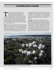
Photo 2.1 presents a photograph of the tailings facility area looking northwest, with the tailings<br />
impoundment outlined in yellow and the main dam located at the left end of the yellow outline.<br />
Photo 2.1 Tailings Facility General Area, looking northwest.<br />
Although the area has the potential for permafrost to occur, none of the test pits and drillholes in<br />
the vicinity of the dam encountered permafrost. Minor permafrost was noted in one of the test<br />
pits at one of the previously proposed dam site locations.<br />
March 2009 Page 6
<strong>Wolverine</strong> <strong>Project</strong> Tailings and Related Infrastructure Design and Construction Plan<br />
2.1 Geology and Seismicity<br />
Klohn Crippen Berger.M09234A04<br />
Version 2009-02<br />
The geology characterization and seismicity assessment are included in Appendix I and<br />
summarized in the following sections.<br />
2.1.1 Geology<br />
The <strong>Wolverine</strong> Lake area lies within the limits of the McConnell Glaciation (youngest of the<br />
four glaciations in Yukon Territory) and most of the geomorphic features in the area are related<br />
to this glaciation. McConnell glacial ice covered this area between 14,000 and 35,000 years ago.<br />
As the McConnell ice retreated and down-wasted, a complex network of ice tongues developed<br />
in valley bottoms. Morainal deposits are found at lower to mid-elevation and valley floors, and<br />
may contain a more complex assemblage of glacio-fluvial, colluvial and fluvial sediments<br />
(Mougeot 1996). The main glacial soils in the vicinity of the tailings impoundment consist of up<br />
to 20 m of silty sand and gravel, with cobbles overlying bedrock.<br />
The area is underlain by bedrock strata generally paralleling the valley trend, i.e., striking in the<br />
direction of the valley. The bedrock consists of an interlayered sequence of volcanoclastic<br />
(rhyolite and quartz feldspar) and carbonaceous/argillic sediments, overlain with basalt. The iron<br />
formation, which hosts the ore zone, trends northwest-southeast throughout the project area.<br />
2.1.2 Seismicity<br />
The most seismically active region near the <strong>Wolverine</strong> <strong>Project</strong> area is along the plate boundaries<br />
in the coastal and offshore area. The most significant inland seismicity occurs along segments of<br />
the Denali fault zone system, where the seismicity rate is an order of magnitude lower than that<br />
in the coastal region. The region between the Denali and Tintina systems is relatively a seismic,<br />
with relatively few and small earthquakes.<br />
Data on recent earthquakes that occurred within about 600 km from the project site (61.41°N and<br />
130.09°W) from September 1899 to December 2005 was extracted from the Canadian<br />
EPB/GSC/PGC database and are shown on Figure 2-1. No earthquakes with magnitude greater<br />
than 5 have occurred within 200 km from the site. However, a magnitude 5 event did occur about<br />
28 km northwest of the project site with a focal depth of 5 km on May 12, 1999.<br />
March 2009 Page 7
<strong>Wolverine</strong> <strong>Project</strong> Tailings and Related Infrastructure Design and Construction Plan<br />
Latitude (deg-North)<br />
66<br />
65<br />
64<br />
63<br />
62<br />
61<br />
60<br />
59<br />
58<br />
57<br />
Approximate Distance from Site (km)<br />
-600 -500 -400 -300 -200 -100 0 100 200 300 400 500 600<br />
YFF<br />
OGL<br />
EGA<br />
DEN<br />
QCB<br />
GLB<br />
RIC<br />
SYT<br />
QCF<br />
NCM<br />
Klohn Crippen Berger.M09234A04<br />
<strong>Wolverine</strong><br />
<strong>Project</strong> Site<br />
CCM<br />
Notes:<br />
1. Only earthquakes with magnitude M > 3 within a grid of 56.03 o N-66.79 o N<br />
and 118.84 o W-141.33 o W and from September 1899 to December 2005 are shown.<br />
2. Epicentre data taken from Canadian EPB/GSC/PGC database and<br />
3. Distances from project site are approximate, assuming one degree of latitude and<br />
longitude as 111.43 km and 53.37 km, respectively.<br />
50 10 0 150 200 300 400 500 Approximate<br />
Radius (km)<br />
Version 2009-02<br />
March 2009 Page 8<br />
MCK<br />
Watson<br />
Lake<br />
NRMT<br />
MAGNITUDE RANGE<br />
8-8.9<br />
NFT<br />
7-7.9<br />
6-6.9<br />
5-5.9<br />
4-4.9<br />
3-3.9<br />
-140 -138 -136 -134 -132 -130 -128 -126 -124 -122 -120<br />
Longitude(deg-West)<br />
GSC-H Model Seismic Souce Zone Boundary<br />
SYT GSC-H Model Seismic Source Zones<br />
Figure 2-1 Location Map of Recent Regional Epicentres<br />
The probabilistic seismic hazard assessment has been determined using both the GSC-H and<br />
GSC-R seismic source zonal models developed by the Geological Survey of Canada for the new<br />
National Building Code of Canada 2005 (Adams and Halchuk 2003). The model incorporated<br />
600<br />
500<br />
400<br />
300<br />
200<br />
100<br />
0<br />
-100<br />
-200<br />
-300<br />
-400<br />
-500<br />
-600<br />
Approximate Distance from Site (km)
<strong>Wolverine</strong> <strong>Project</strong> Tailings and Related Infrastructure Design and Construction Plan<br />
Klohn Crippen Berger.M09234A04<br />
Version 2009-02<br />
the work conducted by Atkinson (2004) for a site-specific seismic hazard analysis for Faro,<br />
Yukon (62.2°N and 133.2°W). In that analysis, an apparent linear alignment of seismicity in the<br />
region along the Tintina Trench fault system was grouped into a Tintina seismic source zone.<br />
This Tintina source zone was incorporated in the model for computing site peak horizontal<br />
acceleration as shown in Figure 2-2 and Table 2.1.<br />
Table 2.1 Probabilistic Evaluation of Peak Horizontal Ground Acceleration at <strong>Project</strong><br />
Site<br />
ANNUAL<br />
PROBABILITY OF<br />
EXCEEDANCE<br />
RETURN PERIOD<br />
(years)<br />
PEAK GROUND ACCELERATION PGA (g)<br />
GSC-H 2005 MODEL<br />
GSC-H 2005 MODEL<br />
WITH TINTINA SOURCE<br />
ZONE<br />
0.0021 475 0.08 0.097<br />
0.001 1,000 0.10 0.12<br />
0.00040 2,475 0.14 0.15<br />
0.0001 10,000 0.20 0.22<br />
Annual Probability of Exceedance<br />
0.1<br />
0.01<br />
0.001<br />
0.0001<br />
475 Year<br />
Return Period<br />
1,000 Year<br />
Return Period<br />
2,475 Year<br />
Return Period<br />
0.00 0.05 0.10 0.15 0.20 0.25 0.30<br />
Peak Horizontal Ground Acceleration (g)<br />
10,000 Year<br />
Return Period<br />
Figure 2-2 Peak Horizontal Ground Acceleration at Various Probability of Annual<br />
Exceedance<br />
March 2009 Page 9
<strong>Wolverine</strong> <strong>Project</strong> Tailings and Related Infrastructure Design and Construction Plan<br />
Klohn Crippen Berger.M09234A04<br />
Version 2009-02<br />
Two earthquake scenarios were considered for the deterministic evaluation for the site peak<br />
horizontal ground acceleration as shown in Table 2.2: a local earthquake at the site with<br />
magnitude M=6; and an earthquake at the Tintina Fault with magnitude M=7.2. The<br />
deterministic assessment was used to assess the potential for liquefaction of the foundation soils,<br />
as discussed in Section 7.2 of this report.<br />
Table 2.2 Deterministic Evaluation of Peak Horizontal Ground Acceleration at <strong>Project</strong><br />
Site<br />
EARTHQUAKE<br />
SCENARIO<br />
MAGNITUDE<br />
EPICENTRAL<br />
DISTANCE (km)<br />
FOCAL DEPTH<br />
(km)<br />
PEAK GROUND<br />
ACCELERATION<br />
PGA (g)<br />
Local 6 0 2.9 0.34<br />
Tintina Fault 7.2 53 2.9 0.11<br />
2.2 Hydrology and Groundwater<br />
The estimated mean annual precipitation for the <strong>Wolverine</strong> Minesite is 570 mm, and the<br />
estimated mean annual evaporation rate is 400 mm. Average snowpack for the minesite is<br />
estimated to be 175 mm snow-water equivalent.<br />
Table 2.3 presents the ratios of dry and wet year annual precipitations and mean monthly runoff<br />
flows, to the average mean annual precipitation and mean monthly flows, respectively (Madrone<br />
2006). Additional hydrology data is provided in Appendix III Part I.<br />
Table 2.3 Ratios of Dry and Wet Year Annual Precipitations and Mean Monthly<br />
Runoff Flows<br />
EVENT 200 yr<br />
dry<br />
Annual<br />
Precipitation<br />
Mean Monthly<br />
Runoff flow<br />
100 yr<br />
dry<br />
10 yr<br />
dry<br />
RATIO<br />
AVERAGE<br />
March 2009 Page 10<br />
10 yr<br />
wet<br />
100 yr<br />
wet<br />
200 yr<br />
wet<br />
1,000 yr<br />
wet<br />
0.59 0.62 0.76 1 1.16 1.39 1.44 1.56<br />
0.61 0.64 0.78 1 1.25 1.52 1.60 1.77<br />
Table 2.4 presents the monthly precipitation distribution and the monthly runoff distribution. A<br />
summary of monthly flows for various site locations are shown in Table 2.5.
<strong>Wolverine</strong> <strong>Project</strong> Tailings and Related Infrastructure Design and Construction Plan<br />
Klohn Crippen Berger.M09234A04<br />
Table 2.4 Monthly Precipitation and Runoff Distribution<br />
MONTH % PRECIPITATION % FLOW<br />
January 7 0<br />
February 6 0<br />
March 5 0<br />
April 4 1<br />
May 7 19<br />
June 11 35<br />
July 14 17<br />
August 11 9<br />
September 10 9<br />
October 9 6<br />
November 8 3<br />
December 8 1<br />
Version 2009-02<br />
Table 2.5 Expected Mean Monthly and Annual Flows (m 3 /s) for Selected Locations<br />
STATION W31 W16 W12 W44 W14<br />
MONTH<br />
GO CREEK AT<br />
AIRSTRIP<br />
(4.7 km 2 )<br />
GO CREEK AT<br />
HAWKOWL<br />
CREEK<br />
(10.2 km 2 )<br />
GO CREEK AT<br />
MONEY CREEK<br />
(36.5 km 2 )<br />
<strong>TAILINGS</strong> DAM<br />
CATCHMENT<br />
(1.05 km 2 )<br />
MONEY CR.<br />
DOWNSTREAM<br />
OF GO (238 km 2 )<br />
Jan 0.007 0.017 0.065 0.0015 0.479<br />
Feb 0.007 0.016 0.061 0.0015 0.435<br />
Mar 0.007 0.015 0.055 0.0014 0.392<br />
Apr 0.010 0.021 0.079 0.0021 0.537<br />
May .0.048 0.108 0.410 0.0099 2.938<br />
Jun 0.045 0.111 0.490 0.0079 4.324<br />
Jul 0.034 0.083 0..352 0.0062 2.970<br />
Aug 0.021 0.050 0.212 0.0038 1.772<br />
Sep 0.020 0.047 0.198 0.0036 1.642<br />
Oct 0.018 0.044 0.180 0.0035 1.450<br />
Nov 0.013 0.030 0.119 00025 0.906<br />
Dec 0.009 0.021 0.083 0.0018 0.631<br />
Year 0.022 0.051 0.207 0.0041 1.643<br />
March 2009 Page 11
<strong>Wolverine</strong> <strong>Project</strong> Tailings and Related Infrastructure Design and Construction Plan<br />
Klohn Crippen Berger.M09234A04<br />
Version 2009-02<br />
In the vicinity of tailings impoundment area, the groundwater table is generally sloping<br />
southwest following the trend of the topography. Near the downstream end of the impoundment<br />
basin at TH05-8 and MW05-7 (refer to Drawing D-3002), the piezometric pressure in the<br />
bedrock is slightly artesian (few meters above ground) and the water table rises, with the<br />
topography, towards the dam abutments. In general, the groundwater table in the overburden is<br />
slightly lower than that in the bedrock except at TH05-9. The groundwater table exhibits<br />
seasonal variation, reaching highest elevation after spring runoff season.<br />
Table 2.6 summarizes piezometric elevations monitored during September 7-9, 2005 at test hole<br />
locations and monitoring wells installed in the general tailings impoundment area.<br />
March 2009 Page 12
<strong>Wolverine</strong> <strong>Project</strong> Tailings and Related Infrastructure Design and Construction Plan<br />
Klohn Crippen Berger.M09234A04<br />
Version 2009-02<br />
Table 2.6 Summary of Piezometric Elevations in Tailings Impoundment Area<br />
MONITORING WELL<br />
OR TEST HOLE<br />
GROUND<br />
El.<br />
(m)<br />
TOP OF<br />
RISER PIPE<br />
ABOVE<br />
GROUND<br />
(m)<br />
DEPTH TO<br />
WATER FROM<br />
TOP OF RISER<br />
PIPE (m)<br />
PIEZOMETRIC<br />
El.<br />
MW05-6A (Bedrock) 1348 0 6.93 1341.07<br />
MW05-6B (Overburden) 1348 0.12 7.32 1340.8<br />
March 2009 Page 13<br />
(m)<br />
PRESSURE<br />
GAUGE<br />
ABOVE<br />
GROUND<br />
MW05-7A (Bedrock) 1286 0.46 0.17 1286.29 0.53 -<br />
MW05-7B (Overburden) 1286 0.37 0.5 1285.87<br />
TH05-7A (Bedrock) 1305 0.53 10.26 1295.27<br />
(m)<br />
ARTESIAN<br />
PRESSURE<br />
(ABOVE<br />
PRESSURE<br />
Gauge el.)<br />
TH05-8A (Bedrock) 1290 0.18 - >1290.25 0.25
<strong>Wolverine</strong> <strong>Project</strong> Tailings and Related Infrastructure Design and Construction Plan<br />
Klohn Crippen Berger.M09234A04<br />
Version 2009-02<br />
The main groundwater aquifer is the 10 m to 20 m thick overburden overlying bedrock within<br />
the Go Creek Valley. Downstream of Go Creek valley, which appears to be a hanging valley, the<br />
morphology changes to a broader terraced valley where much thicker deposits of post glacial<br />
outwash soils provide a larger groundwater flow regime.<br />
2.3 Water Quality<br />
Surface and groundwater quality data is included in Appendix III and the main observations are<br />
summarized below.<br />
Surface Water Quality in the Tailings Impoundment Area<br />
Baseline surface water quality samples (n=13) were collected from October 2005 to August 2007<br />
from Station W44, which is located on a small stream that drains through the tailings<br />
impoundment area. The data indicate that water quality in this small stream is dominated by<br />
meteoric waters of low hardness, low alkalinity and circum-neutral pH. The water is low in<br />
sulphate, nutrients and metal content is generally low, with slightly higher concentrations<br />
observed during peak snow melt periods when TSS levels are elevated. Data is provided in<br />
Appendix III Part 3.<br />
Groundwater<br />
Baseline groundwater quality data was collected from 2005 to 2008 at the tailings impoundment<br />
area monitoring wells: MW05-2A, MW05-2B, MW05-6A, MW05-6B, and MW05-7B (refer to<br />
Drawing D-3002) and data is included in Appendix III Part 3. Two new monitoring wells<br />
(MW08-13 and MW08-14), were installed in late October 2008 and water quality data from<br />
MW08-13 is provided in Appendix III. Sampling was not conducted at MW08-14 as it was<br />
frozen. The results indicate that the groundwater has a neutral to slightly alkaline pH and low<br />
conductivity values. The groundwater is generally calcium-bicarbonate (Ca-HCO3) type water,<br />
which is associated with glacio-fluvial sediments and ground moraine.<br />
March 2009 Page 14
<strong>Wolverine</strong> <strong>Project</strong> Tailings and Related Infrastructure Design and Construction Plan<br />
3. <strong>DESIGN</strong> CRITERIA<br />
Klohn Crippen Berger.M09234A04<br />
Version 2009-02<br />
The <strong>Wolverine</strong> <strong>Project</strong> tailings dam is designed to national standards, using the Canadian Dam<br />
Association – Dam Safety Guidelines (CDA, 2007). The main design criteria are summarized in<br />
Table 3.1 and discussed in the following sections.<br />
Storage Capacity:<br />
Tailings<br />
Flood Management during Operation:<br />
Diversion of upland catchment<br />
Flood storage in impoundment<br />
Flood discharge<br />
Table 3.1 Summary of Tailings Dam Design Criteria<br />
ITEM CRITERIA<br />
2.03 Mt @ 1.6 t/m 3 =1.267 Mm 3<br />
1: 100 year peak flow<br />
200 year return period (approx. 0.3 m of pond rise) + seasonal<br />
storage of water<br />
Exceeding 1:200 year peak flow, no dam overtopping during<br />
1:10,000 year<br />
Seismic Return Period During Operation and Closure 10,000 year return period (PGA = 0.22g)<br />
Geotechnical Factors of Safety during operations:<br />
Static<br />
Pseudo-static, seismic coefficient = 0.125 (a = 0.125 g)<br />
Environment - Operations<br />
Tailings pond<br />
Allowable seepage flows out of impoundment<br />
Closure<br />
Flood Handling<br />
Diversion Ditches<br />
Spillway<br />
Geotechnical stability Safety Factor<br />
Static<br />
Pseudo-static, seismic coefficient = 0.125 (a = 0.125 g)<br />
Geochemical stability<br />
Suspended sediment stability<br />
Allowable Seepage<br />
FS = 1.3 (end of construction) and FS = 1.5 (operational)<br />
FS = 1.1 (note FS = 1.0 required by CDA 2007)<br />
Saturated tailings to prevent acid rock drainage<br />
Effluent treated until water quality meets discharge limits<br />
Seepage < 0.5 L/s. Contaminated seepage from the TSF, if<br />
present, will be collected and pumped to tailings pond<br />
Diversion ditches to be decommissioned<br />
1:10,000 year return period routed peak flow<br />
FS = 1.5<br />
FS = 1.15 (Seed, 1979) (note FS = 1.0 required by CDA 2007)<br />
0.5 m minimum water cover to maintain saturation to prevent<br />
acid rock drainage.<br />
1.0 m of soil cover<br />
Seepage
<strong>Wolverine</strong> <strong>Project</strong> Tailings and Related Infrastructure Design and Construction Plan<br />
3.1 Dam Classification Assessment<br />
Klohn Crippen Berger.M09234A04<br />
Version 2009-02<br />
The recent Canadian Dam Association Dam Safety Guidelines (CDA 2007) were adopted to<br />
confirm the classification of the tailings facility for seismic and flood protection criteria. The<br />
dam classification is primarily based on the consequence of failure and the guideline is<br />
summarized in Table 3.2. To assess the potential consequence of failure, the industry practice is<br />
to conduct a “dam break” assessment, which assumes that the dam could fail and determines<br />
what the potential run-out of tailings and water could be.<br />
The selected dam classification, based on the dam break analysis presented in Section 3.1.1, is<br />
“High” to “Very High”, and the criteria for Very High has been selected for design. The use of<br />
the Very High rating provides additional security for the long term performance of the tailings<br />
facility after closure.<br />
March 2009 Page 16
<strong>Wolverine</strong> <strong>Project</strong> Tailings and Related Infrastructure Design and Construction Plan<br />
Dam Class<br />
Population<br />
at risk<br />
(Note 1)<br />
Klohn Crippen Berger.M09234A04<br />
Table 3.2 Dam Classification Guideline (CDA 2007)<br />
Loss of Life<br />
(Note 2)<br />
Low None 0<br />
Significant Temporary<br />
only<br />
Unspecified<br />
High Permanent 10 or fewer<br />
Very High Permanent 100 or fewer<br />
Extreme Permanent<br />
More than<br />
100<br />
Incremental losses<br />
Environmental and Cultural<br />
Values<br />
Minimal short-term loss<br />
No long-term loss<br />
-No significant loss or<br />
deterioration of fish or wildlife<br />
habitat<br />
-Loss of marginal habitat only<br />
-Restoration or compensation in<br />
kind highly possible<br />
-Significant loss or deterioration<br />
of important fish or wildlife<br />
habitat<br />
-Restoration or compensation in<br />
kind highly possible<br />
-Significant loss or deterioration<br />
of critical fish or wildlife habitat<br />
-Restoration or compensation in<br />
kind possible but impractical<br />
-Major loss of critical fish or<br />
wildlife habitat<br />
-Restoration or compensation in<br />
kind impossible<br />
Version 2009-02<br />
Infrastructure and Economics<br />
-Low economic losses; area contains<br />
limited infrastructure or services<br />
-Losses to recreational facilities,<br />
seasonal workplaces, and<br />
infrequently used transportation<br />
routes<br />
-High economic losses affecting<br />
infrastructure, public transportation,<br />
and commercial facilities<br />
-Very high economic losses affecting<br />
important infrastructure or services<br />
(e.g., highway, industrial facility,<br />
storage facilities for dangerous<br />
substances)<br />
-Extreme losses affecting critical<br />
infrastructure or services (e.g.<br />
hospital, major industrial complex,<br />
major storage facilities for dangerous<br />
substances)<br />
Note 1. Definitions for population at risk:<br />
None - There is no identifiable population at risk, so there is no possibility of loss of life other than through<br />
unforeseeable misadventure.<br />
Temporary - people are only temporarily in the dam-breach inundation zone (e.g., seasonal cottage use, passing<br />
through on transportation routes, participating in recreational activities).<br />
Permanent - The population at risk is ordinarily located in the dam-breach inundation zone (e.g., as permanent<br />
residents); three consequence classes (high, very high, extreme) are proposed to allow for more detailed estimates of<br />
potential loss of life (to assist in decision-making if the appropriate analysis is carried out).<br />
Note 2. Implications for loss of life:<br />
Unspecified - The appropriate level of safety required at a dam where people are temporarily at risk depends on the<br />
number of people, the exposure time, the nature of their activity, and other conditions. A higher class could be<br />
appropriate, depending on the requirements. However, the design flood requirement, for example, might not be higher<br />
if the temporary population is not likely to be present during the flood season.<br />
March 2009 Page 17
<strong>Wolverine</strong> <strong>Project</strong> Tailings and Related Infrastructure Design and Construction Plan<br />
3.1.1 Dam Break Assessment<br />
Klohn Crippen Berger.M09234A04<br />
Version 2009-02<br />
The tailings facility is located in a remote area of Yukon and, except for a campsite on Frances<br />
Lake, there are no major population centres or commercial and industrial activities downstream<br />
of the impoundment. In the event of an incident at the tailings impoundment, the discharge from<br />
the facility would enter Go Creek and then Money Creek. Money Creek discharges into Frances<br />
Lake, which is located east of the mine about 40 km downstream of the tailings impoundment.<br />
The most significant infrastructure crossing along this flow path is the Robert Campbell<br />
Highway over Money Creek, just before the creek enters Frances Lake.<br />
The expected peak flood outflow from the tailings pond occurring as a result of a dam breach<br />
was estimated using charts compiled by MacDonald and Monopolis (1984), and by Wahl (1998),<br />
based on dam failure case studies. It should be noted that these charts are based on failures of<br />
water storage dams. Tailings stored in the tailings ponds have higher viscosity than water and, in<br />
the event of a tailings dam failure, usually not all the tailings are released from the pond.<br />
Furthermore, tailings tend not travel as far downstream as water. The estimated total storage<br />
volume of approximately 1.45 million m 3 (Mm 3 ) at closure in the tailings pond will contain<br />
approximately 1.27 Mm 3 of tailings.<br />
For estimating the peak discharge resulting due to a breach at the <strong>Wolverine</strong> tailings dam, the<br />
following simplifying assumptions were made:<br />
• The total mobilized volume was taken as 100% of the free water in the pond<br />
(0.15 Mm3) plus 30% of the stored tailings (0.40 Mm3); and<br />
• The tailings were assumed to behave the same as water, i.e., the entire volume of<br />
water plus the 30% of tailings is released from the pond and all of it travels<br />
downstream as if it was water.<br />
The analysis of data presented by United States Congress of Large Dams (USCOLD) on tailings<br />
dam failures (USCOLD 1995) indicates that, on average, only 30% of the tailings are released<br />
from the impoundment as a result of a dam failure. Since the charts being used are based on<br />
failures of water storage dams where the entire storage volume above the dam foundation would<br />
March 2009 Page 18
<strong>Wolverine</strong> <strong>Project</strong> Tailings and Related Infrastructure Design and Construction Plan<br />
Klohn Crippen Berger.M09234A04<br />
Version 2009-02<br />
be released, only 30% of the total tailings are assumed to be part of the storage volume for the<br />
dam break analysis of the tailings dam.<br />
The estimated peak outflow released from the dam is 1,850 m 3 /s, which is expected to attenuate<br />
as the flood wave travels downstream. The downstream flows were estimated using the<br />
attenuation charts prepared by Petrascheck and Sydler (1984), and the results are summarized in<br />
Table 3.3.<br />
Table 3.3 Estimated Dam Breach Flood Peaks Downstream of Tailings Dam<br />
LOCATION<br />
DISTANCE FROM DAM<br />
(km)<br />
ESTIMATED PEAK FLOW<br />
(m 3 /s)<br />
At <strong>Wolverine</strong> Tailings Dam 0 1850<br />
Confluence of Go Creek and Money Creek 5 1700<br />
Robert Campbell Highway and Frances Lake 40 1100<br />
The assumptions made and the charts used herein provide approximate estimates of expected<br />
dam breach discharge and downstream attenuation.<br />
As Table 3.3 indicates, little attenuation of the flow is expected by the time the flood peak<br />
reaches Money Creek, but it is expected to decrease to about 60% of the original flow by the<br />
time the flood peak reaches Robert Campbell Highway and Frances Lake. A comparison of the<br />
estimated flood peak resulting from a breach at the tailings dam with the natural stream flows<br />
indicates that the dam breach flood peak will be about 150 times the naturally expected 200-year<br />
peak flow in Go Creek above Money Creek, and it will be about 10 times the naturally expected<br />
200-year peak flow in Money Creek at the Robert Campbell Highway. The expected attenuation<br />
of the flood peak presented in Table 3.3 is based on the assumption that the tailings released<br />
from the dam migrate downstream the same as water. In reality, the tailings will not be as mobile<br />
and a substantial portion of the tailings are expected to be deposited close to the dam.<br />
The potential consequences of the dam failure, that support the dam rating of “Very High”, are<br />
summarized below for the key indicators included in Table 3.2.<br />
March 2009 Page 19
<strong>Wolverine</strong> <strong>Project</strong> Tailings and Related Infrastructure Design and Construction Plan<br />
Populations at Risk and Loss of Life<br />
Klohn Crippen Berger.M09234A04<br />
Version 2009-02<br />
There are no permanent populations that would be at risk and loss of life would be limited to<br />
temporary personnel in the vicinity. Therefore, the “Population at Risk” classification is<br />
“Significant”.<br />
Environmental and Cultural Effects<br />
The flood flow would damage and have a negative impact on the aquatic habitat in the flow path.<br />
The tailings released from the pond as well as those left in the pond are expected to become acid<br />
generating, if left exposed to atmosphere for many years, and would remain acid generating<br />
indefinitely until the oxidation process is complete. The potential effect could be substantial loss<br />
or deterioration of important fish or wildlife habitat and could require recovery of all of the<br />
tailings and construction of a new containment facility. Given the potential for large socioeconomic<br />
and environmental damage, as well as substantial clean-up costs, the tailings<br />
impoundment is classified as a “Very High” consequence facility<br />
Infrastructure and Economics<br />
There is limited infrastructure and no industrial facilities downstream of the dam. The potential<br />
effect of a dam break would be limited to damage to the Robert Campbell Highway and Money<br />
Creek bridge. The potential infrastructure and economic damage could be significant.<br />
Restoration or compensation would be highly possible. Therefore the dam classification is<br />
“High”.<br />
3.2 Earthquake, Flood and Seepage Criteria<br />
Recommended design criteria (CDA 2007) for various dam classifications are summarized in<br />
Table 3.4 and the selected criteria are discussed in the following sections.<br />
March 2009 Page 20
<strong>Wolverine</strong> <strong>Project</strong> Tailings and Related Infrastructure Design and Construction Plan<br />
Klohn Crippen Berger.M09234A04<br />
Version 2009-02<br />
Table 3.4 Inflow Design Flood and Suggested Design Earthquake Levels for<br />
Consequence Classes (CDA 2007)<br />
DAM CLASS<br />
AEP<br />
[NOTE 1] IDF [NOTE 2] EDGM [NOTE 3]<br />
Low 1/100 1/500<br />
Significant Between 1/100 and 1/1000 [note 4] 1/1,000<br />
High 1/3 between 1/1000 and PMF [note 5] 1/2,500<br />
Very High 2/3 between 1/1000 and PMF [note 5] 1/5,000 [note 6]<br />
Extreme PMF [note 5] 1/10,000 [note 6]<br />
Acronyms: AEP, annual exceedance probability; EDGM, earthquake design ground motion; IDF, inflow design<br />
flood; PMF, probable maximum flood.<br />
Note 1. As defined in Table 2-2, Dam Classification<br />
Note 2. Extrapolation of flood statistics beyond 1/1000 year flood (10 -3 AEP) is discouraged.<br />
Note 3. AEP levels for EDGM are to be used for mean rather than median estimates of the hazard.<br />
Note 4. Selected on the basis of incremental flood analysis, exposure, and consequences of failure.<br />
Note 5. PMF has no associated AEP. The flood defined as “1/3 between 1/1000 year and PMF” or “2/3 between<br />
1/1000 year and PMF” has no defined AEP.<br />
Note 6. The EDGM value must be justified to demonstrate conformance to societal norms of acceptable risk.<br />
Justification can be provided with the help of failure modes analysis focused on the particular modes that can<br />
contribute to failure initiated by seismic event. If the justification cannot be provided, the EDGM should be<br />
1/10,000.<br />
Design Earthquakes<br />
The tailings facility is classified as “Very High” consequence and the CDA recommendation<br />
seismic guideline is for an earthquake return period of 1:5000 years. As per QML-0006<br />
Condition 16.2, the tailings facility must withstand a minimum of a 10,000 year return design<br />
earthquake, and has been designed to this standard. For the seepage collection dam, the<br />
recommended return period is 475 years to reflect the low consequence of failure and the short<br />
service life.<br />
Design Floods<br />
The design flood criteria selected for various components of the water management facilities<br />
associated with the tailings impoundment are summarized in Table 3.5. The corresponding dam<br />
safety criteria for a “Very High” consequence dam is “2/3 between 1/1,000 and PMF” and a<br />
March 2009 Page 21
<strong>Wolverine</strong> <strong>Project</strong> Tailings and Related Infrastructure Design and Construction Plan<br />
Klohn Crippen Berger.M09234A04<br />
Version 2009-02<br />
criterion of 10,000 year return period has been used, as per requirements of QML-0006<br />
Condition 16.2.<br />
The expected operating life of the mine was also taken into account in the selection of the design<br />
floods for temporary facilities, such as the surface runoff diversion ditches, the starter dam<br />
emergency spillway and the seepage collection system. During operations all facilities related to<br />
the tailings impoundment will be monitored, and personnel, equipment and materials will be<br />
readily available in the event that remedial measures are required. Therefore, lower design<br />
criteria for temporary facilities have been selected.<br />
Table 3.5 Selected Flood Design Criteria for Water Management Facilities<br />
FACILITY<br />
Surface water<br />
diversion ditches<br />
Starter Dam<br />
Emergency Spillway<br />
Tailings Dam Closure<br />
Spillway<br />
Seepage Collection<br />
Pond Spillway<br />
Tailings Pond flood<br />
storage allowance<br />
below spillway level<br />
during mine operation<br />
Tailings Dam<br />
Spillways<br />
Note: IDF = Inflow Design Flood<br />
MIN. <strong>DESIGN</strong><br />
FLOOD RETURN<br />
PERIOD (YEARS)<br />
FLOOD STORAGE<br />
& FREEBOARD<br />
ALLOWANCE<br />
100 - -<br />
10,000 Storage for 200 year<br />
flood<br />
COMMENTS<br />
Assume that upland surface water<br />
diversion ditches have failed. Spillway<br />
also must be able to pass the 10,000year<br />
flood without overtopping the<br />
dam.<br />
10,000 - Assume that upland surface water<br />
diversion ditches have been<br />
decommissioned.<br />
100 - Assume that upland surface water<br />
diversion ditch is functioning.<br />
- 0.3 m For routing of design flood through the<br />
tailings pond after closure, the initial<br />
water level is assumed to be at the<br />
spillway level, i.e., flood storage<br />
allowance is assumed to be zero.<br />
- 1.5 m Minimum freeboard is defined as the<br />
difference in elevation between the top<br />
of the dam without camber and the<br />
maximum pond level that would result<br />
from routing the IDF through the<br />
reservoir. This is approximately 2.0 m<br />
above spillway invert.<br />
March 2009 Page 22
<strong>Wolverine</strong> <strong>Project</strong> Tailings and Related Infrastructure Design and Construction Plan<br />
Design “Allowable” Seepage Assessment<br />
Klohn Crippen Berger.M09234A04<br />
Version 2009-02<br />
This section presents the design basis for determining the “allowable” seepage rate from the<br />
impoundment. The assessment is based on determining the fate and transport of potential<br />
contaminants from the impoundment to the receiving environment. During operations, seepage<br />
through the dam will be collected with a seepage collection ditch and pond for return to the<br />
impoundment, as required. In addition, a portion of seepage from the impoundment (potentially<br />
25% of total seepage) may bypass the seepage collection system and mix with the regional<br />
groundwater flow. The groundwater flow system downstream of the seepage collection dam can<br />
be characterized as follows:<br />
• In the immediate vicinity of Go Creek and the tailings impoundment, the<br />
groundwater flow system within the glaciofluvial soils overlying bedrock could<br />
have an estimated groundwater flow of 15 L/s.<br />
• The area near W12, upstream of the confluence of Money Creek and Go Creek<br />
appears to have a similar overburden cover as near the dam and the estimated<br />
groundwater flow is 60 L/s.<br />
• In the vicinity of W14, downstream of the confluence of Money Creek and Go<br />
Creek, the geomorphology changes to a terrace glacial outwash regime with a<br />
thicker overburden aquifer, which could have an estimated groundwater flow of<br />
420 L/s.<br />
A portion of the groundwater will report to the deeper groundwater system and flow towards Go<br />
Creek and to the groundwater regime in the vicinity of W14.<br />
The criteria for allowable seepage was estimated on the basis of a simple dilution model, using<br />
predicted concentrations of cadmium, selenium and zinc in the impoundment and the potential<br />
seepage flows from the impoundment. In addition, a factor of 10% has been applied to account<br />
for attenuation and adsorption, which will occur along the flow path. Table 3.6 summarizes the<br />
concentrations of cadmium, selenium and zinc in the tailings/DMS float pore water, baseline<br />
values at W14 and “tolerable” seepage based on the groundwater “dilution” flow and a 10%<br />
factor for adsorption. The pore water chemistry is primarily controlled by the process water<br />
chemistry during operations (see Section 5.3). Supporting data includes shake flask extraction<br />
tests and aging tests of the tailings supernatant.<br />
March 2009 Page 23
<strong>Wolverine</strong> <strong>Project</strong> Tailings and Related Infrastructure Design and Construction Plan<br />
Klohn Crippen Berger.M09234A04<br />
Version 2009-02<br />
Table 3.6 Summary of Concentrations of Parameters of Potential Concern and<br />
“Tolerable” Seepage Rates<br />
PARAMETER OF<br />
POTENTIAL<br />
CONCERN<br />
CCME<br />
LIMIT<br />
(mg/L)<br />
BASELINE<br />
CONCENTRATION<br />
(mg/L)<br />
IMPOUNDMENT<br />
PORE WATER -<br />
RANGE (mg/L)<br />
“TOLERABLE”<br />
SEEPAGE (L/s)*<br />
W-14<br />
“TOLERABLE”<br />
SEEPAGE (L/s)*<br />
W-12<br />
Cadmium 0.000 017 0.000 05 0.01 20 3<br />
Selenium 0.001
<strong>Wolverine</strong> <strong>Project</strong> Tailings and Related Infrastructure Design and Construction Plan<br />
4. GEOTECHNICAL CHARACTERIZATION<br />
4.1 Site Investigations<br />
Klohn Crippen Berger.M09234A04<br />
Version 2009-02<br />
Geotechnical site investigations for the tailings facility were carried out from July to September<br />
2005. The investigations included 6 drill holes, 2 groundwater monitoring wells and 23 test pits,<br />
which are shown in plan in Drawing D-3002. Testing results, and drill hole and test pit logs are<br />
included in Appendix I. Subsoil profiles are shown in Drawing D-3003.<br />
4.2 Geotechnical Testing<br />
Geotechnical laboratory testing included visual classification, moisture content, and gradation<br />
tests for overburden samples retrieved from field investigations. Additionally, standard Proctor<br />
compaction tests, triaxial permeability and direct shear strength tests were carried out on the<br />
potential borrow materials for the dam fill and on the tailings. These results are summarized in<br />
Table 4.1, and test results are included in Appendix I.<br />
Table 4.1 Summary of Engineering Properties Determined from Laboratory Tests on<br />
Dam Fill and Tailings<br />
TYPE OF<br />
MATERIAL<br />
UNIT WEIGHT<br />
γdry (kN/m3)<br />
EFFECTIVE SHEAR STRENGTH<br />
Cohesion<br />
c' (kPa)<br />
Friction Angle<br />
φ′ (degree)<br />
HYDRAULIC<br />
PERMEABILITY<br />
k (m/s)<br />
Dam Fill ~2.1 0 37 3 E-8<br />
Tailings ~1.85 0 34 7 E-8<br />
Test results for dam fill and tailings were obtained by consolidated-undrained triaxial shear tests<br />
with permeability measurement after consolidation and pore pressure measurement during shear.<br />
The consolidation stresses used in the laboratory were selected to simulate the field condition.<br />
The tailings testing carried out in 2006 was on a 50:50 mixture of F11 and F12 (Zn, Rougher<br />
Scavenger Tail) and F23 and F32 (Zn 1 st Cleaner Scavenger Tail). Additional tests were carried<br />
out in 2008 on a mixture of 80% rougher tailings and 20% cleaner tailings and the test results are<br />
summarized in Table 4.2.<br />
March 2009 Page 25
<strong>Wolverine</strong> <strong>Project</strong> Tailings and Related Infrastructure Design and Construction Plan<br />
Klohn Crippen Berger.M09234A04<br />
Table 4.2 Summary of Tailings Laboratory Test Results<br />
TEST TEST RESULTS<br />
Specific gravity S.G = 3.7 and 3.9<br />
Gradation % finer than 75 micron = 83% to 92%<br />
5 day jar settling test Settled density of 71%, equivalent to 1.45 t/m 3<br />
Version 2009-02<br />
Consolidation Density at final stress state (75 kPa average) = 80% solid by weight, equivalent to<br />
1.8 t/m 3<br />
Permeability k < 10 -8 m/s<br />
Coefficient of consolidation: Cv = 10 -2 cm 2 /s<br />
Based on the settling and consolidation tests, an average in situ density of 1.6 t/m 3 has been used<br />
for storage volume calculations.<br />
Subsequent to the testing of the tailings, detail design of the mill has removed the dense media<br />
separation circuit. The potential effects of removing the DMS on the tailings are:<br />
• Slight decrease in specific gravity, which could reduce the settled density by 5%.<br />
However, a conservative density has been assumed and actual densities will be<br />
measured during operations on the basis of bathymetry surveys and production<br />
records; and<br />
• Negligible change to the permeability because the grinding circuit would still be<br />
anticipated to produce a similar gradation tailings.<br />
March 2009 Page 26
<strong>Wolverine</strong> <strong>Project</strong> Tailings and Related Infrastructure Design and Construction Plan<br />
5. GEOCHEMICAL CHARACTERIZATION<br />
Klohn Crippen Berger.M09234A04<br />
Version 2009-02<br />
Geochemical assessments were conducted on tailings, dam construction material, and tailings<br />
supernatant water. A summary is provided below and the databases included in Appendix II. In<br />
addition, an update on the humidity cell testing overseen by Marsland Environmental Associates<br />
to September 2008 is included in Appendix II.<br />
The assessment presented in the following sections is based on the original design basis of using<br />
the dense media separation to segregate low sulphide gangue rock. Detailed mine design has<br />
eliminated the dense media float circuit and reduced the amount of dilution rock being mined.<br />
The potential effects on the geochemistry of removing the DMS are:<br />
• The tailings may have a slightly higher NP/AP ratio due to the addition of neutral<br />
dilution material; and<br />
• The neutral metal leaching properties are anticipated to be similar because the<br />
main contaminants are associated with the sulphide tailings and the process<br />
solutions.<br />
5.1 Tailings Geochemistry<br />
To assess the geochemical characteristics of the tailings, four ore composite types were prepared<br />
and examined. The four samples were prepared with lock cycle tests (LCT) carried out to<br />
simulate the milling process, which produces three tailings sub-streams: ~2% pre-float<br />
concentrate (PFC), 88% rougher tails (Ro), and 10% cleaner scavenger tails (CS). The composite<br />
ore samples include the following:<br />
• Combined overall diluted ore composite (Comb OD Comp) tailings: Combines<br />
the three tailings streams generated by using ore and dilution rock from both<br />
<strong>Wolverine</strong> and Lynx ore zones (LCT3).<br />
• Combined overall ore composite (Comb Overall Ore Comp) tailings: Combines<br />
the tailings generated from using only ore from the <strong>Wolverine</strong> and Lynx ore<br />
zones, and does not include any dilution rock. The sample is a composite of two<br />
lock cycle tests (LCT1 & LCT2).<br />
March 2009 Page 27
<strong>Wolverine</strong> <strong>Project</strong> Tailings and Related Infrastructure Design and Construction Plan<br />
Klohn Crippen Berger.M09234A04<br />
Version 2009-02<br />
• Combined <strong>Wolverine</strong> composite ore with dilution rock (Comb Wolv D Comp)<br />
tailings: Combines all three tailings streams generated from ore with dilution rock<br />
from the <strong>Wolverine</strong> ore zone (LCT4).<br />
• Combined Lynx ore with dilution rock composite (Comb Lynx D Comp) tailings:<br />
Combines all three tailings streams generated from ore with dilution rock from the<br />
Lynx ore zone (LCT5).<br />
Mineralogy<br />
Mineral assemblage percentages for the four composite tailings samples were assessed using<br />
optical microscopy on the four samples and the results are summarized in Table 5.1.<br />
In addition, quantitative phase analysis using x-ray diffraction (XRD) with Rietveld refinement<br />
was carried out, to identify the carbonate and sulphide species. The results suggest the onset of<br />
acidic conditions may have the potential to release metal (loids) from mineral phases, likely from<br />
the sulphide phases confirmed by mineralogical characterization. Furthermore, elements that are<br />
mobile under neutral pH conditions (e.g., Se, Zn, etc.) may have the potential to be released.<br />
Table 5.1 Mineral Assemblages and Modal Abundances by Optical Microscopy (wt. %)<br />
Mineral Comb OD Comp<br />
Comb Overall Ore<br />
Comp<br />
Comb Wolv D<br />
Comp<br />
Comb Lynx D<br />
Comp<br />
Pyrite 53.1 60.1 38.3 60.3<br />
Quartz 20.9 17.1 26.7 16.7<br />
Carbonate 10.5 10.6 14.2 11.6<br />
Muscovite 11.9 5.2 14.3 8.9<br />
Chlorite 1.0 1.1 0.9 0.0<br />
Sphalerite 1.1 1.6 1.3 1.8<br />
Pyrrhotite 0.5 1.6 2.1 0<br />
Amphibole 0 0.6 0.5 0<br />
Arsenopyrite 0.3 0.8 0 0.3<br />
Pyroxene 0.2 0.3 1.5 0.0<br />
Chalcopyrite 0.5 0.4 0.2 0.0<br />
Galena 0.0 0.4 0 0.8<br />
Biotite 0 0.2 0 0<br />
Magnetite 0 0.1 0 0<br />
Total 100 100 100 100<br />
March 2009 Page 28
<strong>Wolverine</strong> <strong>Project</strong> Tailings and Related Infrastructure Design and Construction Plan<br />
Acid Base Accounting<br />
Klohn Crippen Berger.M09234A04<br />
Version 2009-02<br />
The results of the ABA tests carried out on all of the tailings sub-streams are summarized in<br />
Table 5.2. All samples have high sulphide content and a low Neutralization Potential Ratio<br />
(NPR) of less than one, and are classified as having a high potential for producing acid rock<br />
drainage. However, the samples have enough NP (carbonate neutralization potential of 20 kg to<br />
100 kg CaCO3/t) to remain at a near-neutral pH, when initially exposed to oxygen. This is<br />
confirmed with the relatively high paste pH values of 6.9 to 7.85. In addition, most samples<br />
indicate the presence of non-carbonate neutralization potential, possibly from the muscovite,<br />
clinochlore and kaolinite, indicated by the mineralogical analysis.<br />
Shake Flask Tests<br />
The results of the shake flask extraction tests from the four combined tailings samples are<br />
included in Appendix II. The shake flask extraction tests show that the final pH was near neutral<br />
to slightly alkaline and ranged from pH 7.3 to pH 8.4. The initial exposure of tailings to<br />
atmospheric conditions should result in minimal trace metal(loid) releases, except for the<br />
Combined Overall Ore Composite tailings, which shows Cd (0.134 mg/L), Se (0.20 mg/L), Tl<br />
(0.022 mg/L) and Zn (6.87 mg/L) releases. The major ions Ca 2+ , Na + , Mg 2+ , Mn 2+ , Cl - , SO4 2- and<br />
thiosalts also show releases, most likely due to the dissolution of gypsum (CaSO4) and other salts<br />
and sulfosalts present at low abundances.<br />
March 2009 Page 29
<strong>Wolverine</strong> <strong>Project</strong> Tailings and Related Infrastructure Design and Construction Plan<br />
Table 5.2 Tailings Acid Base Accounting Results for Tailings Sub-Streams<br />
Parameter Units<br />
Overall<br />
Comp<br />
LCT2<br />
Ro<br />
Klohn Crippen Berger.M09234A04<br />
Overall<br />
Comp<br />
LCT2<br />
Cl Sc<br />
Overall<br />
Comp<br />
LCT2<br />
Comb<br />
OD<br />
Ro<br />
OD<br />
Cl Sc<br />
Version 2009-02<br />
Paste pH - 7.79 7.26 7.42 7.85 6.69 7.27 7.68 6.91 7.35 7.67 6.45 7.36<br />
Fizz Rate - 3 3 3 3 2 2 3 2 2 3 2 2<br />
Total S %S 22.3 39.5 29.2 17.5 43.0 26.6 12.3 39.4 19.7 23.7 48.4 31.2<br />
Acid Leachable SO4 2- %S 1.07 6.98 2.51 0.02 1.18 2.04 0.45 1.63 1.74 0.92 6.45 0.74<br />
Sulphide S %S 20.2 28.5 25.0 15.7 39.0 22.9 10.1 34.1 15.7 20.4 39.4 27.8<br />
Insoluble SO4 2- %S 0.005 0.005 0.005 0.005 0.005 0.005 0.005 0.005 0.005 0.005 0.005 0.005<br />
Organic S %S 1.10 4.00 1.73 1.72 2.83 1.67 1.79 3.64 2.34 2.35 2.61 2.68<br />
AP kg CaCO3/t 631 891 781 491 1220 715 315 1070 489 638 1230 869<br />
Sobek NP kg CaCO3/t 103 41.8 72.8 114 21.9 82.5 119 32.1 94.6 111 20.9 49.4<br />
Net NP kg CaCO3/t -528 -849 -708 -377 -1198 -632 -196 -1038 -395 -526 -1209 -820<br />
Sobek NP/AP - 0.16 0.05 0.09 0.23 0.02 0.12 0.38 0.03 0.19 0.17 0.02 0.06<br />
Carb NP kg CaCO3/t 72.6 23.4 59.4 91.4 20.5 98.3 105 24.6 106 94.4 22.1 52.3<br />
Carb NP/AP - 0.11 0.56 0.08 0.19 0.02 0.14 0.33 0.02 0.22 0.15 0.02 0.06<br />
TOC %C na na na 0.54 0.43 0.62 0.69 0.75 0.98 0.49 0.25 0.48<br />
TIC %C na na na 1.32 0.11 0.94 1.39 0.14 1.2 1.30 0.21 0.79<br />
C(t) %C 1.72 0.87 1.48 1.86 0.54 1.56 2.07 0.88 2.14 1.79 0.46 1.27<br />
na= not analyzed<br />
March 2009 Page 30<br />
OD<br />
Comb<br />
Wolv<br />
Ro<br />
Wolv<br />
Cl Sc<br />
Wolv<br />
Comb<br />
Lynx<br />
Ro<br />
Lynx<br />
Cl Sc<br />
Lynx<br />
Comb
<strong>Wolverine</strong> <strong>Project</strong> Tailings and Related Infrastructure Design and Construction Plan<br />
Humidity Cell Testing<br />
Klohn Crippen Berger. M09234A04<br />
Version 2009-02<br />
Four humidity cells were initiated in mid 2005 and results are included in Appendix II. Two<br />
humidity cells containing Overall Ore Composite (OC) and Overall Ore Diluted (OD) samples<br />
are operational and an updated report to September 2008 is included in Appendix II. A summary<br />
illustrating the changes to water quality during the test period (using week 15 and week 160 as<br />
indicator weeks) is presented in Table 5.3 and the main observations of the testing to date<br />
include:<br />
• The pH has remained circum-neutral over other the period except for a few<br />
anomalous spikes, which appear to be due to variability in reaction rates within<br />
the samples;<br />
• The sulphate production rates have shown a slight decline over the testing period<br />
and both samples have similar sulphate loading rates (approximately<br />
100 mg/kg/wk);<br />
• A conservative interpretation of potential time to sulphide depletion in the<br />
laboratory is 3 years to 10 years for the OD and OC samples respectively, which<br />
could equate to >25 years in natural conditions; and<br />
• The elemental loading rates for soluble selenium and zinc appear relatively<br />
constant, although the zinc loading rate for the OC samples had a zinc loading<br />
rate that declined, then increased slightly from week 90 to week 150. Average<br />
loading rates are approximately 2 mg/kg/wk for zinc and 0.08 mg/kg/wk for<br />
selenium. Typical Se concentrations in the leachate for week 160 were in the<br />
order of 0.05 mg/L to 0.1 mg/L.<br />
The testing indicates that the lag time for acid generation will be many years and that elemental<br />
loading of zinc and selenium, via leachates, could continue for a number of years.<br />
March 2009 Page 31
<strong>Wolverine</strong> <strong>Project</strong> Tailings and Related Infrastructure Design and Construction Plan<br />
Klohn Crippen Berger. M09234A04<br />
Version 2009-02<br />
Table 5.3 Typical Humidity Cell Leachate Concentrations for Combined OC<br />
Composite and Combined OD Tailings<br />
Parameter Units OC Tailings OD Tailings<br />
Leachate concentrations (selected Weeks)<br />
Week 15 Week 160 Week 15 Week 160<br />
Leachate<br />
Volume<br />
ml 401 498 431 424<br />
pH units 6.87 6.67 6.97 6.72<br />
Alkalinity mg CaCO3/L 7 7 11 5<br />
Acidity mg CaCO3/L 163 3 434 1<br />
Conductivity µS/cm 551 564 1540 651<br />
SO4 2- mg/L 250 270 890 270<br />
Cl mg/L 0.1 0.1<br />
F mg/L 0.08 0.14<br />
NO3 - mg N /L 0.025 0.025<br />
NH3 + NH4 + mg N /L 0.5 0.2<br />
Thiosalts mg S2O3/L 156 5 384 5<br />
CN(T) mg/L 0.005 0.001<br />
CNO mg/L 0.05 0.5<br />
CNS mg/L<br />
Hg µg/l 0.05 0.05<br />
Ag mg/L 0.0025 0.000005 0.0025 0.000005<br />
Al mg/L 0.005 0.005 0.005 0.0027<br />
As mg/L 0.006 0.003 0.017 0.0037<br />
Cd mg/L 0.0935 0.197 0.0677 0.0456<br />
Cu mg/L 0.0025 0.0051 0.0031 0.0050<br />
Pb mg/L 0.019 0.0171 0.0026 0.00188<br />
Sb mg/L 0.025 0.00291 0.025 0.00124<br />
Se mg/L 0.285 0.112 1.18 0.147<br />
Tl mg/L 0.0075 0.0035 0.014 0.00232<br />
Zn mg/L 4.04 8.19 3.01 2.29<br />
Note: All metals are dissolved concentrations<br />
March 2009 Page 32
<strong>Wolverine</strong> <strong>Project</strong> Tailings and Related Infrastructure Design and Construction Plan<br />
5.2 Borrow for Dam Construction Materials<br />
Klohn Crippen Berger. M09234A04<br />
Version 2009-02<br />
Borrow materials from within and adjacent to the impoundment will be used for constructing the<br />
earthfill tailings dam. Geochemical tests, including shake flask tests and acid base accounting<br />
(ABA) tests, were carried out for samples collected from the test pits located in the impoundment<br />
and from the project borrow area located northwest of the tailings facility (see Drawing D-3002),<br />
and results are included in Appendix II. These tests indicate that the borrow materials have a low<br />
leaching potential, and are not potentially acid generating.<br />
5.3 Supernatant Water Chemistry<br />
The tailings supernatant water quality acquired from the lock cycle test work is summarized in<br />
Table 5.4. During operations, variations outside of this range may occur with fluctuations or<br />
alterations in reagent dosage during ore processing. Certain dissolved parameters (e.g., Na, K, Cl<br />
and SO4) may tend to re-circulate through the mill in the reclaim water. Eventually these<br />
parameters will reach a re-circulating equilibrium concentration, that may in part be controlled<br />
by the solubility limit of the parameter of interest (e.g., sulphate can be expected to eventually be<br />
limited by gypsum solubility in the presence of calcium addition as lime in the mill circuit). The<br />
tailings supernatant chemistry will be typical of the pore water quality in the tailings. The main<br />
parameter of potential concern is selenium, which had a typical concentration of approximately<br />
9.5 mg/L.<br />
March 2009 Page 33
<strong>Wolverine</strong> <strong>Project</strong> Tailings and Related Infrastructure Design and Construction Plan<br />
Klohn Crippen Berger. M09234A04<br />
Table 5.4 Tailings Supernatant Geochemistry<br />
Parameter Concentration<br />
(mg/L)<br />
pH 7.4 - 7.9<br />
Ammonia-N 0.1 - 0.35<br />
Nitrate 0.30<br />
CN-total 0.02 - 3.5<br />
Thiosalts 400 - 600<br />
SO4 500 - 1500<br />
Al 0.02 - 0.14<br />
Sb 0.02 - 0.065<br />
As 0.002 - 0.1<br />
Cd 0.001 - 0.005<br />
Cu 0.012 - 0.11<br />
Fe
<strong>Wolverine</strong> <strong>Project</strong> Tailings and Related Infrastructure Design and Construction Plan<br />
Klohn Crippen Berger. M09234A04<br />
Version 2009-02<br />
exposed to atmospheric oxygen and carbon dioxide, as would be the case in the tailings<br />
impoundment during temporary suspension of milling activities (e.g., maintenance shutdowns)<br />
or post-closure. At closure, or during sustained shutdown, there will be a short lag time (up to 9<br />
months) until the remaining thiosalts are oxidized and water quality stabilizes. During this period<br />
there is a slight depression in pH, which then rises after the thiosalts are oxidized. Selenium,<br />
cadmium and zinc for some of the samples show elevated concentrations at 120 days (Table 5.5).<br />
Concentrations of some parameters had not reached equilibrium after 120 days.<br />
Additional testing will be conducted during the operations period to refine the estimates of postclosure<br />
tailings pond water quality behaviour.<br />
Table 5.5 Summary of Tailings Aging Tests at 120 Days<br />
Parameter<br />
COMB Overall<br />
ore comp<br />
Comb OD<br />
cOMP<br />
comb <strong>Wolverine</strong><br />
D Comp<br />
comb Lynx D<br />
Comp<br />
pH 7.39 7.16 7.11 7.63<br />
Hardness 860 560 544 813<br />
Sulphate 1200 920 890 1200<br />
Thiosalts
<strong>Wolverine</strong> <strong>Project</strong> Tailings and Related Infrastructure Design and Construction Plan<br />
Klohn Crippen Berger. M09234A04<br />
Version 2009-02<br />
sample was approximately 7 times the pore volume of the sample. The leachate of the subaqueous<br />
columns was collected and analyzed for pH, conductivity, acidity, alkalinity, thiosalts,<br />
anions (F - , Cl - , SO4 2- and NO3 - ), cyanide (CN), thiocyanate (CNS), cyanate (CNO), ammonia +<br />
ammonium (NH3 + NH4 + ) and a suite of dissolved metal(loid)s via ICP-MS (including mercury)<br />
by SGS Lakefield.<br />
Table 5.6 Summary of Subaqueous Column Results after 8 Weeks<br />
Parameter COMB Overall ore comp (OC)<br />
Comb OD<br />
cOMP (OD)<br />
pH 7.86 7.65<br />
Sulphate 52 38<br />
Thiosalts 5 5<br />
Total Cyanide 0.005 0.005<br />
Ammonia 0.1 0.7<br />
Ag 0.00005 0.00005<br />
As 0.0025 0.002<br />
Cd 0.00005 0.000015<br />
Cu 0.004 0.0005<br />
Pb 0.0005 0.0003<br />
Hg 0.00005 0.0014<br />
Sb 0.0092 0.0228<br />
Se 0.008 0.010<br />
Tl 0.0001 0.0021<br />
Zn 0.005 0.009<br />
Note: All metals are dissolved concentrations (mg/L). Italicized values indicate measured valued less than detection<br />
limit, and listed as one half of the detection limit; Bold values indicated measured values in excess of 10x CCME<br />
guideline.<br />
The water quality of the leachate stabilized after 4 weeks to typical values shown in Table 5.6.<br />
The test indicates that the water quality improves with time, as the process water is “flushed” out<br />
through seepage. For example, the number of pore water volumes in the four weeks was<br />
approximately 30 times indicating that a leaching water volume of approximately 2 L/kg is<br />
required to “flush” residual contaminants. The actual leaching rates for the tailings impoundment<br />
will be very low due to the geomembrane liner.<br />
March 2009 Page 36
<strong>Wolverine</strong> <strong>Project</strong> Tailings and Related Infrastructure Design and Construction Plan<br />
6. <strong>TAILINGS</strong> IMPOUNDMENT<br />
Klohn Crippen Berger. M09234A04<br />
Version 2009-02<br />
The tailings facility includes a tailings impoundment, L-shaped tailings dam, a seepage recovery<br />
dam and pond, two upland diversion ditches, and a spillway (see Drawing D-3004). The tailings<br />
impoundment site is located in a natural, northwest-southeast trending elongated ephemeral<br />
drainage basin perched on the northeast valley slope of Go Creek (see Drawing D-3001). The<br />
basin is flanked on the downhill side by a natural ridge trending in the same direction that drops<br />
in elevation gently towards the upstream end of the tailings facility, and ends rather abruptly at<br />
the elbow point of the L-shaped tailings dam at the downstream end. The impoundment covers<br />
an area approximately 600 m long and 300 m wide.<br />
Site investigations indicate that the tailings basin is mantled by glacio-morainal deposits, which<br />
may have been altered by the stream flowing along the thalweg. Along the ridge, the depth to<br />
bedrock ranges from 30 m to 40 m, while between the ridge and the northeast valley slope the<br />
depth is shallower, ranging from 20 m to 25 m.<br />
6.1 Storage Capacity<br />
The annual storage requirements are summarized in Table 6.1 and the capacities of the<br />
impoundment with Stage 1 and Stage 2 dams is shown on Figure 6-1. The stage storage curve<br />
has been adjusted to reflect the detailed ground survey that was carried out after stripping of the<br />
dam and impoundment foundation was completed.<br />
In addition to storage of tailings solids, the tailings facility will provide for the following:<br />
• Minimum operational water volume of 40,000 m3 for settling of solids and<br />
operation of pumps ;<br />
• Seasonal storage for average conditions of 60,000 m3;<br />
• 200 year flood storage consisting of 200 yr wet month precipitation with<br />
snowmelt of 37,500 m3; and<br />
• 2 m of freeboard, which provides for routing of the 10,000 year return period<br />
flood event through the spillway (0.5 m) and 1.5 m of freeboard.<br />
March 2009 Page 37
<strong>Wolverine</strong> <strong>Project</strong> Tailings and Related Infrastructure Design and Construction Plan<br />
Elevation (m)<br />
1320<br />
1315<br />
1310<br />
1305<br />
1300<br />
1295<br />
Klohn Crippen Berger. M09234A04<br />
Table 6.1 Tailings Production Rate (t/y) and Volume<br />
Calendar<br />
Year<br />
Operation<br />
Year<br />
Total Tailings<br />
Production (TONNES)<br />
Tailings to<br />
Impoundment<br />
(tonnes)<br />
2010 1 1 305,586 159,486<br />
2011 2 484,319 257,910<br />
2012 3 485,645 272,219<br />
2013 4 484,319 231,690<br />
2014 5 484,319 229,410<br />
2015 6 484,319 229,410<br />
2016 7 485,645 230,039<br />
2017 8 484,319 229,410<br />
2018 9 371,805 187,385<br />
Total Tonnage 4,070,275 2,026,960<br />
Total Volumes 2 (m 3 )<br />
1: Based on 184 days of production<br />
na 1,267,000<br />
2: Based on an in situ density of 1.6 t/m 3<br />
Stage 1 Stage 2<br />
Tailings and Water Storage (m³) 520,000 1,328,000<br />
Total Impoundment Volume (m³) 716,000 1,623,000<br />
Stage 1 Dam El. 1306.5 m<br />
WOLVERINE<br />
Stage-Storage Curve<br />
Stage 2 Dam El. 1313.5 m<br />
Freeboard<br />
200 yr Flood Storage<br />
Tailings & Water Storage Height<br />
Version 2009-02<br />
1290<br />
0 200,000 400,000 600,000 800,000 1,000,000 1,200,000 1,400,000 1,600,000 1,800,000<br />
Storage Volume (m 3 )<br />
Figure 6-1 Stage Storage Curve – Tailings Impoundment<br />
March 2009 Page 38
<strong>Wolverine</strong> <strong>Project</strong> Tailings and Related Infrastructure Design and Construction Plan<br />
6.2 Deposition Strategy and Staged Development<br />
Klohn Crippen Berger. M09234A04<br />
Version 2009-02<br />
The tailings will be deposited via several spigot discharges. In approximately the first five years<br />
of operations, tailings will be spigotted from two locations (as shown on Drawing D-3006): a)<br />
from the southeast of the impoundment to push the decant pond towards the north, during<br />
operations; and b) from the north end of the impoundment to cover the geomembrane. The<br />
tailings beach will slope towards the northwest where the water reclaim barge will initially be<br />
located. The tailings will form a beach, which will slope at approximately 1% towards the water<br />
pond. Typical sections, through the impoundment, for Year 2, Year 6 and closure are shown on<br />
Drawing D-1010 and D-3011.<br />
A Surpac spatial model of the impoundment was run to illustrate the deposition of tailings over<br />
the life of the mine. Typical model outputs for tailings deposition are shown on Figure 6-2 to<br />
Figure 6-5, for Year 1, Year 2, Year 6, and closure, respectively (water pond is coloured blue and<br />
the tailings are brown). Typical sections are shown schematically on Drawing D-3010 and<br />
Drawing D-3011 for various stages of operations.<br />
Figure 6-2 Deposition Plan - Year 1<br />
March 2009 Page 39
<strong>Wolverine</strong> <strong>Project</strong> Tailings and Related Infrastructure Design and Construction Plan<br />
Klohn Crippen Berger. M09234A04<br />
Figure 6-3 Deposition Plan - Year 2<br />
Figure 6-4 Deposition Plan - Year 6<br />
Version 2009-02<br />
March 2009 Page 40
<strong>Wolverine</strong> <strong>Project</strong> Tailings and Related Infrastructure Design and Construction Plan<br />
6.3 Liner Design<br />
Klohn Crippen Berger. M09234A04<br />
Figure 6-5 Deposition Plan - Closure<br />
Version 2009-02<br />
The tailings facility is designed to retain water and minimize seepage from the impoundment and<br />
dam. In order to achieve this, A 40 mil LLDPE geosynthetic liner will line the impoundment and<br />
along interior face of the dam. Overburden material in the impoundment will be excavated and<br />
used as general fill for the dam. Typical excavation and fill sections for the impoundment are<br />
shown in Drawings D-3007 and D-3009.<br />
Prior to preparing the foundation base for the liner, a short underdrain will be installed to prevent<br />
uplift pressures from developing beneath the liner in the low area of the impoundment, near the<br />
upstream toe of the dam (See Drawings D-3006 and D-3007). The drain will become redundant<br />
after the liner is covered with water and/or tailings. Following installation of the underdrain, the<br />
foundation base of impoundment will be prepared by heavy compaction of the natural soils.<br />
Local placement of finer material will be required in areas of very coarse gravel or boulders.<br />
March 2009 Page 41
<strong>Wolverine</strong> <strong>Project</strong> Tailings and Related Infrastructure Design and Construction Plan<br />
Klohn Crippen Berger. M09234A04<br />
Version 2009-02<br />
The lining system will be constructed in two stages as shown on Drawings D-3006 and D-3008<br />
Specifications for liner materials and placement are summarized in Section 6.3. The liner will be<br />
anchored in a trench around the perimeter of the impoundment (at the edge of the Stage 1 road<br />
for the Starter Dam and Stage 2 Road for the Ultimate Dam). The liner in the Stage 2 dam<br />
section will have a “backup” low permeability soil zone to provide additional protection in the<br />
event of liner degradation, near surface, due to UV degradation and freeze-thaw actions.<br />
An assessment of the potential leakage for various scenarios (i.e., base case, partially degraded<br />
liner and no liner) is summarized in Table 6.2 and included in Appendix I. The seepage analyses<br />
indicate that the leakage rate out of the impoundment should be on the order of 0.00001 L/s,<br />
which is negligible.<br />
Table 6.2 Summary of Leakage Sensitivity Analysis<br />
ANALYSIS CONDITION<br />
BASIN/LINER<br />
PERMEABILITY (m/s)<br />
TOTAL SEEPAGE (L/sec)<br />
Base Case – Liner with good QA/QC Defect Analysis 0.00001<br />
Partially “Degraded” Liner 10 -10 0.13<br />
Unlined facility 10 -6 6.8<br />
The sensitivity analysis also indicates that the worst-case condition, considering complete<br />
degradation of the liner would result in a seepage rate on the order of 6.8 L/s. Because liner<br />
degradation is often a result of UV effects, complete degradation of the impoundment liner,<br />
which will be covered by tailings, is considered to be highly improbable. As such a more realistic<br />
“worst case” evaluation, considering only partial degradation, suggests that seepage under this<br />
condition would be less than 0.13 L/s. Life of liner estimates are typically > 125 years and are<br />
limited by available service life data. Some designers have suggested a potential life of 300 years<br />
to 400 years. A partially degraded liner would be equivalent to about 3,000 m 2 of area with no<br />
liner.<br />
March 2009 Page 42
<strong>Wolverine</strong> <strong>Project</strong> Tailings and Related Infrastructure Design and Construction Plan<br />
6.4 Tailings Facility Water Balance<br />
Klohn Crippen Berger. M09234A04<br />
Version 2009-02<br />
A water balance for the tailings facility over the 9 year mine life has been carried out and the<br />
complete set of tables is included in Appendix III. The water balances for four scenarios are<br />
summarized in this section, including:<br />
• The first year of tailings facility operation (Year 2);<br />
• The final year of tailings facility operation (Year 8);<br />
• After mine closure, with diversions; and<br />
• After mine closure, without diversions.<br />
The cases were run for the average year, 100 year wet, and 100 year dry. Inflows to the tailings<br />
pond include:<br />
• Surface water runoff and snowmelt from the tailings facility catchment, and direct<br />
precipitation on the tailings facility;<br />
• Milling transport water, which includes: tailings transport water, sewage<br />
treatment plant effluent, underground mine water and collected runoff from the<br />
industrial complex area; and<br />
• Water transferred from the seepage recovery pond to the tailings pond.<br />
Outflows from the tailings facility include:<br />
• Evaporation from the pond;<br />
• Reclaim water recycled to the mill during mining operation;<br />
• Water lost to tailing voids as porewater;<br />
• Water pumped to the water treatment plant for treatment and subsequent<br />
discharge; and<br />
• Seepage losses from the tailings pond.<br />
March 2009 Page 43
<strong>Wolverine</strong> <strong>Project</strong> Tailings and Related Infrastructure Design and Construction Plan<br />
Klohn Crippen Berger. M09234A04<br />
Version 2009-02<br />
The groundwater table is near surface and after placement of tailings, the groundwater gradients<br />
will be downward. Therefore, the contribution of groundwater into the impoundment is<br />
considered negligible.<br />
The tailings pond has a total natural catchment area of about 105 ha. With the upland diversion<br />
ditches in place, the reduced tailings facility catchment is about 16 ha.<br />
Table 6.3 presents the results of the average annual water balance for the four scenarios. As the<br />
table indicates, there will be surplus water of approximately 5 m 3 /hr in the tailings pond during<br />
mine operation for the average year. The surplus will increase to approximately 9 m 3 /hr for the<br />
1:100 year wet year, and a water neutral condition is expected to occur during the 1:100 year dry<br />
year. The average annual water balance for the complete mine life and the average monthly<br />
water balances for the life of the project are included in Appendix III.<br />
The water balances for the closure scenarios indicate that there will be surplus water during the<br />
average year and the 1:100 year wet and dry years, with and without the upland diversion ditches<br />
in place. The upland diversion ditches will be decommissioned after mine closure to ensure that<br />
water cover on the deposited tailings is maintained.<br />
Table 6.3 Tailings Pond Annual Water Balances for Four Scenarios<br />
CONDITION<br />
NET AVERAGE WATER SURPLUS (m 3 /hr)<br />
AVERAGE 100 YR DRY 100 YR WET<br />
Year 2 operations with diversions 4.6 -0.5 8.5<br />
Year 8 operations with diversions 5.8 0.2 10.2<br />
Closure with diversions 7.6 2.0 12.0<br />
Closure without diversions 16.6 6.3 24.6<br />
6.5 Water Quality Management<br />
The water balance shows that during operations, over 90% of the water entering the<br />
impoundment is tailings slurry water. During operations, the impoundment will have a net water<br />
surplus, as indicated in the water balance presented in Section 6.5. Discharge from the<br />
March 2009 Page 44
<strong>Wolverine</strong> <strong>Project</strong> Tailings and Related Infrastructure Design and Construction Plan<br />
Klohn Crippen Berger. M09234A04<br />
Version 2009-02<br />
impoundment will be managed to maintain receiving water quality, which will comprise two<br />
main components:<br />
• Excess water will be stored in the tailings impoundment during the low flow<br />
months of November to April, and treated and discharged during the high flow<br />
months of May to October.<br />
• Discharge concentrations and flows will be managed to meet A Licence QZ04-<br />
065 requirements.<br />
The Starter Impoundment has sufficient capacity to store excess water in the first few years of<br />
operations. This will allow for pilot testing and detailed design of the water treatment plant<br />
during the initial years of operations without the requirement for discharge.<br />
March 2009 Page 45
<strong>Wolverine</strong> <strong>Project</strong> Tailings and Related Infrastructure Design and Construction Plan<br />
7. <strong>TAILINGS</strong> DAM<br />
Klohn Crippen Berger. M09234A04<br />
Version 2009-02<br />
The tailings dam is “L-shaped” in plan (see Drawing D-3004), with the short leg of the “L”<br />
alignment extending across a side valley from the east to the west for a length of approximately<br />
250 m. The dam alignment then bends around and follows the trend of a flanking ridge for<br />
another 450 m towards the northwest. The maximum dam height is 16.5 m and 23.5 m high at<br />
project start up and after Year 2 of mining operations, respectively. The dam section has a crest<br />
width of 6 m and a 2H:1V downstream slope and a 2H:1V upstream slope (see Drawing<br />
D-3007).<br />
The tailings dam is a compacted, homogeneous earthfill embankment dam with an upstream<br />
impervious geosynthetic liner. The liner will cover the base of the tailings impoundment and<br />
upstream face of the dam up to the ultimate dam crest level (see Drawing D-3007 and Drawing<br />
D-3009). In addition, a 5 m wide low permeability glacial till soil zone will be placed adjacent to<br />
the liner in the upper 4 m of the Ultimate Dam to provide a contingency against near surface<br />
liner degradation due to ultra-violet or freeze-thaw effects.<br />
The dam will be constructed in two stages. The Starter Dam will be constructed to elevation<br />
1306.5 m in 2009, one year prior to mill start-up. The dam will be raised 7 m using the<br />
downstream construction method to the final elevation at 1313.5 m in Year 2 of mine operation<br />
(2011). During operations there will be storage for tailings plus operations water, and capacity<br />
for the 200 year flood. Starter and Ultimate Dam spillways will be constructed to pass larger<br />
flood events (see Drawing D-3004).<br />
On closure, a 1.0 m thick layer of granular soil/rockfill will be placed over the tailings to reduce<br />
the potential for fine solids to become re-suspended. The cover material could consist of the local<br />
borrow material, which is a silty sand and gravel, with cobbles. Trial placement of the cover<br />
would be carried out to confirm its suitability. In addition, a 0.5 m minimum depth of water over<br />
the stored tailings will provide an oxygen barrier to prevent acid generation and metal leaching<br />
of the solids. An ultimate spillway will modified as necessary to function as the closure spillway.<br />
March 2009 Page 46
<strong>Wolverine</strong> <strong>Project</strong> Tailings and Related Infrastructure Design and Construction Plan<br />
Klohn Crippen Berger. M09234A04<br />
Version 2009-02<br />
There will be 1.5 m of freeboard (2 m over spillway invert) above the normal pond water level to<br />
provide long term security against wave run-up, crest erosion and temporary spillway blockage.<br />
The seepage collection dam is located approximately 150 m downstream of the main dam (see<br />
Drawing D-4005). The seepage dam consists of an unlined compacted earthfill embankment,<br />
with a minimum 5 m wide crest at elevation 1284.6 m, and outer slopes at 2H:1V. The seepage<br />
dam will become part of the mine access road and the crest width will be widened to suit the<br />
road requirements.<br />
7.1 Geotechnical Parameters<br />
The dam foundation consists of up to 20 m thick competent till-like overburden overlying<br />
bedrock. A layer of about 0.3 m thick topsoil overlies most of the tailings impoundment area.<br />
Test pits excavated in the vicinity of the tailings basin indicate that most of the borrow materials<br />
are available from within the footprint of the impoundment.<br />
Table 7.1 summarizes the geotechnical properties of materials used in the seepage and limit<br />
equilibrium slope stability analyses. These properties are based on field and laboratory test data<br />
acquired for the project and supplemented by general properties available in literature.<br />
Table 7.1 Geotechnical Properties Used in the Slope Stability Analyses<br />
MATERIAL<br />
UNIT WEIGHT 1<br />
γ bulk (kN/m 3 )<br />
EFFECTIVE SHEAR STRENGTH<br />
Cohesion<br />
c’ (kPa)<br />
Friction<br />
φ′ (deg)<br />
Foundation soils 22 0 34<br />
Foundation bedrock 27 0 40<br />
Dam Fill 22 0 36<br />
Glacial Till 22 0 36<br />
Tailings 22 0 25<br />
Geomembrane liner - - -<br />
1 Bulk unit weight is the in situ wet density.<br />
March 2009 Page 47
<strong>Wolverine</strong> <strong>Project</strong> Tailings and Related Infrastructure Design and Construction Plan<br />
7.2 Slope Stability Analyses<br />
Klohn Crippen Berger. M09234A04<br />
Version 2009-02<br />
Static and pseudo-static stability analyses were carried out using the computer program SLOPE-<br />
W (Geo-Slope 2004) and the Morgenstern-Price method to determine the factor of safety.<br />
Analyses were carried out on sections for the Starter Dam, Ultimate Dam, and seepage collection<br />
dam. The results are summarized in Table 7.2. A summary of the stability analyses and figures<br />
depicting the analysis results are provided in Appendix I, Part VI.<br />
Pseudo-static slope stability analyses were carried out using a seismic coefficient (kh) of 0.125,<br />
corresponding to a design earthquake magnitude of 7.2, based on interpolation from Seed (1979).<br />
In the analyses, no seismic-induced excess pore pressure was assumed in either the dam or<br />
foundation material.<br />
Table 7.2 Summary of Safety Factors for Tailings Dam and Seepage Dam<br />
DAM<br />
STATIC<br />
FACTORS OF SAFETY<br />
PSEUDO-STATIC 1<br />
Starter Dam 1.6 1.3<br />
Ultimate Dam 1.6 1.2<br />
Seepage Dam 1.5 1.2<br />
1 Pseudo-static analysis used a seisimic coefficient = 0.125 g.<br />
2 Starter Dam elevation analyses was 1306.5 m and Ultimate Dam elevation analysed was 1313.5 m…..….<br />
The geosynthetic liner will be anchored in a trench, as shown on Drawing D-3007, which is<br />
sufficient to maintain the stability of the liner sliding along the liner/dam fill interface.<br />
March 2009 Page 48
<strong>Wolverine</strong> <strong>Project</strong> Tailings and Related Infrastructure Design and Construction Plan<br />
Dam Foundation Liquefaction Assessment<br />
Klohn Crippen Berger.M09234A04<br />
Version 2009-02<br />
The liquefaction assessment was carried out in general accordance with the Seed simplified<br />
approach as described in Youd et al. (2001). The earthquake induced Cyclic Stress Ratios (CSR)<br />
were computed using the Seed’s simplified relationship for level ground conditions. The Cyclic<br />
Resistance Ratios (CRR) were estimated based on Standard Penetration Test (SPT) (N1)60cs<br />
values derived from the measured SPT and Large Penetration Test (LPT) blow count data. The<br />
factor of safety against liquefaction (FOSLiq), which is defined as the ratio of CRR to CSR was<br />
determined to evaluate the liquefaction potential of granular soils at the site. Table 7.3 shows the<br />
liquefaction assessment based on the LPT data at test holes TH05-07 and TH05-08 and SPT data<br />
at test holes, TH05-09 and TH05-10.<br />
Based on the seismic hazard analyses, the following two deterministically based design<br />
earthquake scenarios were considered in the liquefaction assessment:<br />
Scenario 1 (Probabilistic): Earthquake with magnitude M7 and Peak Horizontal<br />
Ground Acceleration (PHGA) of 0.22 g.<br />
Scenario 2 (Deterministic): Earthquake with magnitude M6 and PHGA of 0.34 g.<br />
The PHGAs listed above are representative for the “firm ground” conditions and they were<br />
amplified at the surface. The conventional method was used to determine the LPT/SPT blow<br />
counts NLPT/NSPT. If refusal was reached after 150 mm of penetration during the LPT or SPT<br />
testing, the LPT/SPT blow counts were estimated based on the data up to the point of refusal.<br />
As can be seen from Table 7.3, the measured SPT and LPT data at these test hole locations<br />
indicate that liquefaction will not occur under either design earthquake scenario.<br />
March 2009 Page 49
<strong>Wolverine</strong> <strong>Project</strong> Tailings and Related Infrastructure Design and Construction Plan<br />
TEST<br />
HOLE<br />
TH-07-7<br />
TH05-8<br />
TH05-9<br />
TH05-10<br />
Klohn Crippen Berger.M09234A04<br />
Version 2009-02<br />
Table 7.3 Dam Foundation Liquefaction Assessment Based on LPT/SPT Data<br />
DEPTH<br />
(m)<br />
SPT/<br />
LPT<br />
SPT or LPT<br />
BLOWCOUNT<br />
NLPT or NSPT<br />
SPT<br />
(N 1) 60cs<br />
EARTHQUAKE<br />
SCENARIO 1<br />
(M=7, PGA=0.22g)<br />
EARTHQUAKE<br />
SCENARIO 2<br />
(M=6, PGA=0.34g)<br />
CRR CSR FOSLiq CRR CSR FOSLi 1.52 LPT 101 112 >0.6 0.38 >1.5 >0.8 0.45 >1.8<br />
3.05 LPT 81 89 >0.6 0.37 >1.5 >0.8 0.44 >1.9<br />
4.57 LPT 58* 52 >0.6 0.37 >1.5 >0.8 0.44 >1.9<br />
6.10 LPT 60* 46 >0.6 0.37 >1.5 >0.8 0.43 >1.9<br />
9.14 LPT 70* 44 >0.5 0.36 >1.5 >0.8 0.42 >1.9<br />
12.19 LPT Refusal - - 0.33 - - 0.39 -<br />
15.24 LPT Refusal - - 0.29 - - 0.35 -<br />
18.29 LPT Refusal - - 0.26 - - 0.31 -<br />
21.34 LPT Refusal - - 0.23 - - 0.27 -<br />
24.38 LPT Refusal - - 0.21 - - 0.25 -<br />
1.52 LPT 40* 44 >0.6 0.38 >1.5 >0.8 0.45 >1.8<br />
3.05 LPT 47* 51 >0.6 0.37 >1.5 >0.8 0.44 >1.9<br />
4.57 LPT 48* 43 >0.6 0.37 >1.5 >0.8 0.44 >1.9<br />
6.10 LPT 42* 32 >0.6 0.37 >1.5 >0.8 0.43 >1.9<br />
9.14 LPT 50* 31.5 0.36 >1.5 >0.8 0.42 >1.9<br />
12.19 LPT 60* 33.5 0.33 >1.5 >0.7 0.39 >1.9<br />
15.24 LPT 120* 59.4 0.29 >1.5 >0.7 0.35 >1.9<br />
18.29 LPT Refusal - - 0.26 - - 0.31 -<br />
1.52 SPT 57 97 >0.6 0.38 >1.5 >0.8 0.45 >1.8<br />
3.05 SPT 51 86 >0.6 0.37 >1.5 >0.8 0.44 >1.9<br />
4.57 SPT 125 172 >0.6 0.37 >1.5 >0.8 0.44 >1.9<br />
6.10 SPT 40* 48 >0.6 0.37 >1.5 >0.8 0.43 >1.9<br />
9.14 SPT 52* 51 >0.5 0.36 >1.5 >0.8 0.42 >1.9<br />
12.19 SPT Refusal - - 0.33 - - 0.39 -<br />
15.24 SPT Refusal - - 0.29 - - 0.35 -<br />
18.29 SPT Refusal - - 0.26 - - 0.31 -<br />
21.34 SPT Refusal - - 0.23 - - 0.27 -<br />
24.38 SPT Refusal - - 0.21 - - 0.25 -<br />
27.43 SPT - - 0.20 - - 0.24 -<br />
30.48 SPT Refusal - - 0.19 - - 0.23 -<br />
1.52 SPT 40* 68 >0.6 0.38 >1.5 0.8 0.45 >1.8<br />
3.05 SPT 40* 67 >0.6 0.37 >1.5 0.8 0.44 >1.9<br />
Notes: * Refusal reached between 150mm and 450 mm penetration and NLPT /NSPT estimated based on blow<br />
counts up to the point of refusal; LPT = Large Penetration Test ; SPT = Standard Penetration Test<br />
March 2009 Page 50
<strong>Wolverine</strong> <strong>Project</strong> Tailings and Related Infrastructure Design and Construction Plan<br />
8. WATER MANAGEMENT <strong>INFRASTRUCTURE</strong><br />
Klohn Crippen Berger.M09234A04<br />
Version 2009-02<br />
The water management infrastructure associated with the tailings impoundment and dam<br />
includes the following (refer to Drawing D-3001):<br />
• Operational diversions: Diversion Ditches A and B to direct clean surface water<br />
runoff around the tailings storage facility;<br />
• Seepage collection dam and pond to collect runoff from the downstream dam<br />
face, and as a contingency measure to collect impoundment/dam seepage;<br />
• Starter Dam spillway; and<br />
• Ultimate Dam spillway.<br />
• Tailings and reclaim pipelines and reclaim pump barge<br />
• Water treatment plant (located at the Industrial Complex)<br />
8.1 Surface Water Diversion Ditches<br />
Two diversion ditches associated with the tailings facility are Ditch A and Ditch B as shown in<br />
Drawings D-3032 and D-3033 (Sheets 1 and 2), respectively. The ditches consist of open<br />
channel excavations with corrugated steel pipe (CSP) culverts in areas where the gradients are<br />
steeper than 2%. The ditch side slopes are typically 2H:1V. Approximate lengths and gradients<br />
of the ditches are provided in Table 8.1.<br />
Ditch A:<br />
Runoff from the catchment northwest of the tailings impoundment will be intercepted by the<br />
mine access road upstream of the tailings impoundment. This runoff will be picked up by<br />
Ditch A and conveyed to Go Creek downstream of the airstrip.<br />
Ditch B:<br />
Ditch B will intercept runoff directly north and northeast of the tailings basin. Ditch B will direct<br />
the flow, via a culvert, to Go Creek downstream of the seepage collection pond.<br />
March 2009 Page 51
<strong>Wolverine</strong> <strong>Project</strong> Tailings and Related Infrastructure Design and Construction Plan<br />
Klohn Crippen Berger.M09234A04<br />
Table 8.1 Length and Gradient of Diversion Ditches<br />
Version 2009-02<br />
DIVERSION DITCH<br />
APPROX.<br />
LENGTH (m)<br />
GRADIENT (%)<br />
Minimum Maximum<br />
Ditch A – open section 220 0.5 0.5<br />
Ditch A – culvert section 270 0.47 8.2<br />
Ditch B – open section 760 1.0 1.96<br />
Ditch B- culvert section 510 1.0 9.74<br />
The catchment area for each diversion ditch and the estimated flows for short and long term<br />
duration storms are presented in Table 8.2. These flows were estimated using the Rational<br />
Method with an assumed runoff coefficient of 0.6.<br />
Table 8.2 100-year Flood Flows for Ditches A and B based on Rational Method<br />
DIVERSION<br />
DITCH<br />
CATCHMENT<br />
AREA<br />
(ha)<br />
Rainfall<br />
(mm)<br />
RAINSTORM DURATION<br />
25 Minutes* 24 Hour<br />
Peak Flow<br />
(m 3 /s)<br />
Rainfall<br />
(mm)<br />
Average Flow<br />
(m 3 /s)<br />
Ditch A 67 12 3.2 53 0.25<br />
Ditch B 33 12 1.6 53 0.12<br />
*NOTE: The times of concentration for Ditch A and Ditch B is approximately 25 minutes.<br />
Regional analysis of snowmelt indicates a peak annual daily change in snowpack of about 5 cm<br />
to 15 cm, with a mean of 8.6 cm. Assuming a snowmelt rate of 15 cm/day, the snow water<br />
equivalent is approximated as 15 mm over a 12 hour period. If this snowmelt is added to the<br />
peak design flow values presented in Table 8.2, the flows in Ditch A and Ditch B will increase<br />
by 0.2 m 3 /s and 0.1 m 3 /s, respectively. The mean annual and seasonal flows anticipated in the<br />
ditches are summarized in Table 8.3.<br />
Table 8.3 Mean Annual and Seasonal Flow in Diversion Ditches<br />
MEAN FLOWS (m 3 DIVERSION<br />
/s)<br />
DITCH Mean Annual Summer (High) Winter (Low)<br />
Ditch A 0.007 0.006 – 0.012 ≈ 0<br />
Ditch B 0.006 0.005 – 0.009 ≈ 0<br />
The diversion ditches are temporary structures and will be decommissioned upon mine closure.<br />
Since the expected mine life is only 9 years, and since the likelihood of a 100-year storm event<br />
March 2009 Page 52
<strong>Wolverine</strong> <strong>Project</strong> Tailings and Related Infrastructure Design and Construction Plan<br />
Klohn Crippen Berger.M09234A04<br />
Version 2009-02<br />
occurring during the 9 years is relatively small, the design of the various components of Ditch A<br />
and Ditch B was carried out on the following basis:<br />
• The open channel portion of the ditch is sized to carry the 100-year peak flow<br />
corresponding to the time of concentration, plus a 0.3 m freeboard;<br />
• The open channel portion of the ditch has erosion protection up to the 100-year,<br />
24-hour flow. Erosion and repair of the ditch is expected for flows exceeding the<br />
100-year, 24-hour event. The ditches will be seeded with a native grass species.<br />
• The pipe portion of the ditch was sized to carry the 100-year, 24-hour flow (Table<br />
8.2) plus snowmelt (15 mm snow water equivalent over 12 hours). Pipe diameter<br />
is 800 mm.<br />
8.2 Tailing Dam Spillways<br />
The spillway design is based on routing the design flood through the impoundment without<br />
overtopping the tailings dam. The spillway inlet is a trapezoidal channel with a base width of 3 m<br />
and 2H:1V side slopes. The channel invert at the control section near the dam centerline is<br />
located 2.0 m below the dam crest level.<br />
Site investigations indicated that the insitu material along the spillway channel will consist<br />
primarily of medium dense to dense silty sand and gravel with cobbles.<br />
8.2.1 Hydraulic Design Parameters<br />
Design Flood Selection<br />
The expected 9 year operating life of the mine was taken into account in the selection of the<br />
design floods for temporary facilities, such as the Starter Dam spillway and the Seepage<br />
Collection Dam spillway. A 200-year design return period was selected for the Starter Dam<br />
spillway, with the proviso that the spillway would pass the 10,000-year flood without<br />
overtopping the dam. The spillways were sized based on the criteria and assumptions below.<br />
March 2009 Page 53
<strong>Wolverine</strong> <strong>Project</strong> Tailings and Related Infrastructure Design and Construction Plan<br />
STAGE<br />
Table 8.4 Flood Design Criteria for Tailings Dam Spillways<br />
Klohn Crippen Berger.M09234A04<br />
<strong>DESIGN</strong> FLOOD<br />
RETURN PERIOD<br />
(yrs)<br />
Starter Dam Spillway 200 & 10,000<br />
Ultimate Dam Spillway 10,000<br />
Inflow Hydrographs<br />
COMMENTS<br />
Version 2009-02<br />
Assume that upland surface water diversion ditches<br />
have failed.<br />
Assume that upland surface water diversion ditches are<br />
decommissioned.<br />
The 1 to 30-day flood inflow hydrographs for the Tailings Pond were developed using the<br />
following method:<br />
• The peak runoff for short duration (i.e., 30 min.) rainfall was estimated using the<br />
Rational Method with a runoff coefficient of 1.0; and<br />
• The estimated peak runoff plus 2 to 4 times the estimated long duration (i.e., 1 to<br />
30-day) runoff volume were used to develop the inflow hydrograph.<br />
The above method used to develop the inflow hydrographs tends to conservatively over-estimate<br />
the rise in pond water level, and pond outflow rates.<br />
Flood Routing<br />
The inflow hydrographs for various scenarios were routed through the Tailings Pond in order to<br />
estimate the peak pond water level and the peak spillway discharge. The size of the spillway was<br />
determined such that adequate dam freeboard is available under flood conditions with a<br />
reasonable spillway size. The results of the flood routing are summarized in Table 8.5.<br />
March 2009 Page 54
<strong>Wolverine</strong> <strong>Project</strong> Tailings and Related Infrastructure Design and Construction Plan<br />
DAM<br />
Table 8.5 Tailings Dam Spillways - Design Flood Flows and Freeboards<br />
CATCH-MENT<br />
AREA (ha)<br />
Klohn Crippen Berger.M09234A04<br />
SURFACE<br />
WATER<br />
DIVERSION<br />
DITCHES<br />
<strong>DESIGN</strong> STORM<br />
PEAK<br />
OUTSFLOW<br />
(m 3 /s)<br />
Version 2009-02<br />
DAM FREEBOARD<br />
(m)<br />
16 Functioning 200-yr, 30-min 0.0 2.2<br />
Starter<br />
105 Not functioning<br />
200-yr, 30-min<br />
10,000-yr, 30-min<br />
0.0<br />
0.0<br />
2.1<br />
2.0<br />
10,000-yr, 30-days 8.2 0.8<br />
Ultimate 105 Decommissioned 10,000-yr, 30-min 0.2 1.95<br />
Notes:<br />
1. The peak design flows and freeboard for spillways are based on a 3-m wide trapezoidal channel with 2H:1V side slopes, with channel invert<br />
located 2.0 m below dam crest level.<br />
2. For routing of the 200-year flood through the Starter Dam, the 0.3 m flood storage allowance is assumed to be fully available. That is, the<br />
initial pond level at the beginning of the storm is assumed to be 0.3 m below the spillway invert.<br />
3. For routing of the 10,000-year flood, the flood storage allowance is assumed to be zero for both the Starter Dam and the Ultimate Dam.<br />
4. Minimum freeboard for spillway channel = 0.6 m.<br />
Starter Dam Condition<br />
The 10,000-year, 30-day storm with the diversion ditches assumed to have failed was found to be<br />
more critical in terms of flood discharge rate and dam freeboard. The peak inflow to the pond for<br />
the 10,000-year, 30-day storm is estimated to be about 9.5 m 3 /s, which attenuates to about<br />
8.2 m 3 /s as the flood passes through the pond and the spillway. The pond water level will peak at<br />
El. 1305.7 m, thus leaving a freeboard of about 0.8 m between the dam crest and the peak flood<br />
level.<br />
Ultimate Dam Condition<br />
The 10,000-year, 30-days flood inflows for the Ultimate Dam will be similar to that for the<br />
Starter Dam, but the flow will attenuate to about 7.7 m 3 /s as the flood passes through the pond,<br />
because of the larger pond size.<br />
For the 10,000-year, 30-min. storm, minimal rise in pond water level is expected and about<br />
1.95 m of freeboard between the top of the dam crest and the peak flood level will be available.<br />
For the 10,000-year, 30-days storm, the available freeboard will reduce to about 0.95 m, which is<br />
considered to be reasonable for such an extreme event.<br />
March 2009 Page 55
<strong>Wolverine</strong> <strong>Project</strong> Tailings and Related Infrastructure Design and Construction Plan<br />
Effect of Snowmelt<br />
Klohn Crippen Berger.M09234A04<br />
Version 2009-02<br />
The flood routing presented above is based on rainfall. The effect of combined runoff from<br />
rainfall and snowmelt on the Tailings Pond freeboard was also investigated. The maximum<br />
snowmelt rate of 15 mm/day water equivalent was added as the base flow of the rainfall inflow<br />
hydrograph and the combined runoff was routed through the Tailings Pond.<br />
The flood routing indicates that the pond water level will rise an additional 0.0 m to 0.05 m due<br />
to the snowmelt. Therefore, the freeboard between the top of the dam and the peak flood level<br />
could be 0.05 m less than that indicated in Table 8.5. The reduced freeboard would still be within<br />
the acceptable range of flood freeboard for this type of facility.<br />
8.2.2 Spillway Construction Components<br />
The starter and ultimate spillways will be excavated and lined with a bedding layer and a rip rap<br />
layer as shown on Drawing D-3031 and Drawing D-3034, respectively. In addition, the spillway<br />
alignments cross the main access road to the mine and culverts will be required for both<br />
spillways. Upon closure, the road and culverts would be decommissioned. Erosion protection<br />
will be provided along the spillway channel excavated for removal of the culvert.<br />
8.3 Seepage Collection Infrastructure<br />
8.3.1 Seepage Collection Pond<br />
A Seepage Collection Pond will be constructed downstream of the tailings dam to collect<br />
potential seepage and local runoff for subsequent return to the tailings impoundment. Flow into<br />
the collection pond will be mainly due to precipitation and runoff from the downstream tailings<br />
dam slope and the immediate catchment area of the seepage pond, with little or no seepage<br />
contribution from the lined tailings impoundment. The quality of the pond water will be<br />
monitored and, if it meets discharge quality criteria, it will be discharged to Go Creek; otherwise<br />
it will be pumped into the tailings impoundment.<br />
The seepage collection facility will consist of a 5 m high, 5 m wide dyke forming a collection<br />
pond with a capacity of approximately 5,000 m 3 and a spillway at the dam’s northwest abutment<br />
March 2009 Page 56
<strong>Wolverine</strong> <strong>Project</strong> Tailings and Related Infrastructure Design and Construction Plan<br />
Klohn Crippen Berger.M09234A04<br />
Version 2009-02<br />
(Drawings D-3004 and D-3005). The dam will be a homogeneous earthfill embankment<br />
constructed of silty sand and gravel material by a cut and fill operation to 1284.6 m elevation.<br />
The pond will be approximately 170 m long, 40 m wide at the widest part, and 4 m deep near the<br />
centre of the pond. The seepage dam and spillway will be used during mine operations, and<br />
decommissioned when no longer required at closure.<br />
The maximum pumping rate likely required during operations is 20 L/s. The maximum static<br />
head for pumping water from the Seepage Collection Pond to the Tailings Pond is 27 m to the<br />
Starter Dam crest and 34 m to the Ultimate Dam crest. At the rate of 20 L/s, it will take about<br />
3 days to pump the 5,000 m 3 pond storage capacity. A 20 L/s pumping rate is approximately<br />
equal to the average pond inflow rate for a 5-year, 24-hour rainfall event.<br />
8.3.2 Seepage Dam Spillway<br />
The seepage dam spillway is designed to route flood water through the pond without overtopping<br />
the seepage dam crest. The spillway will consist of an 850 mm diameter culvert discharging<br />
directly into Go Creek and the culvert invert is located 1.5 m below the dam crest (refer to<br />
Drawing D-3005).<br />
The design criterion for the seepage spillway is the 100-year return period (Table 8.6). The<br />
design criterion was selected based on the rationale that the dam is very low (5 m), tailings will<br />
not be stored behind the dam, and there is a low probability that contaminated seepage will be<br />
collected within the pond.<br />
The estimated peak spillway discharge is 0.7 m 3 /s, and the estimated dam freeboard to the flood<br />
level is 0.5 m (Table 8.6). This flow can be passed with a 850 mm diameter corrugated steel pipe<br />
(CSP), which will extend from the west side of the dam to Go Creek, as shown on Drawing<br />
D-3006.<br />
March 2009 Page 57
<strong>Wolverine</strong> <strong>Project</strong> Tailings and Related Infrastructure Design and Construction Plan<br />
Table 8.6 Seepage Dam Spillway Design Flood Flow and Freeboards for<br />
CATCHMENT<br />
AREA (ha)<br />
SURFACE WATER<br />
DIVERSION<br />
DITCHES<br />
Klohn Crippen Berger.M09234A04<br />
<strong>DESIGN</strong> STORM<br />
PEAK <strong>DESIGN</strong><br />
FLOW (m 3 /s)<br />
Version 2009-02<br />
DAM<br />
FREEBOARD (m)<br />
9 Functioning 100-yr, 10-min 0.7 0.5<br />
The spillway culvert will be inspected a minimum of three times per year, with particular<br />
attention to the inspection prior to the spring freshet. This will ensure that the culvert is not<br />
blocked. The performance of the spillway will also be monitored in the operating period during<br />
high runoff periods, while the mine is in operation. Potential problems, if any, will be identified<br />
and remedial actions taken as necessary.<br />
March 2009 Page 58
<strong>Wolverine</strong> <strong>Project</strong> Tailings and Related Infrastructure Design and Construction Plan<br />
9. CONSTRUCTION<br />
9.1 Construction Plan<br />
Klohn Crippen Berger.M09234A04<br />
Version 2009-02<br />
The construction of the tailings facility occurs in three stages over the life of the operation and<br />
includes Starter Dam and Impoundment construction, Ultimate Dam and Impoundment<br />
construction and closure. The main activities occurring in each of the stages are summarized<br />
below.<br />
9.1.1 Stage I Starter Dam and Impoundment (Year 2008 to 2010)<br />
In winter 2008/2009 site preparation work will be completed, including:<br />
• Construction of a drainage channel through the thalweg of the valley to expedite<br />
dewatering of the area, in preparation for other construction activities and spring<br />
runoff.<br />
• Construction of Diversion Ditch A and Diversion Ditch B to reduce the quantity<br />
of water to be managed during construction of the facility in 2009.<br />
• Stripping of organic material from within the impoundment and dam footprint to<br />
allow an “early” construction start-up in 2009; and<br />
Once the winter period is over, and approval for the tailings facility construction is received,<br />
activities scheduled for the spring to fall 2009 period include:<br />
• Construction of liner underdrain;<br />
• Grading and proof rolling of dam impoundment footprint;<br />
• Excavation of borrow from the impoundment interior and construction of the<br />
Starter Dam and Seepage Collection Dam. Construction of the Stage 1 perimeter<br />
access road at El. 1305 m;<br />
• Construction of the Starter Dam Spillway (excavation of channel and placement<br />
of culverts and riprap;<br />
• Installation of dam instrumentation;<br />
• Final grading and proof rolling of impoundment footprint in preparation for<br />
placement of the liner. Placement of liner bedding in areas of “rough” foundation<br />
March 2009 Page 59
<strong>Wolverine</strong> <strong>Project</strong> Tailings and Related Infrastructure Design and Construction Plan<br />
Klohn Crippen Berger.M09234A04<br />
Version 2009-02<br />
base. Excavation of a liner anchor trench around the perimeter of the<br />
impoundment and dam;<br />
• Placement of the liner and backfilling of the liner anchor trench; and<br />
• Placement of material over the liner to form a pad for the water reclaim barge.<br />
Prior to the startup of the mill in June 2010, the following activities will occur to enable full<br />
operation of the tailings facility:<br />
• Selective diversion of surface water from Ditch A and/or Ditch B to provide<br />
initially for 5,000 m 3 , ramping up to 40,000 m 3 of water for start-up of the mill;<br />
• Placement of tailings delivery pipeline and water reclaim pipeline;<br />
• Installation of water reclaim pump barge and associated electrical works.<br />
• Commencement of mill processing and discharge of tailings, and reclaim of<br />
water.<br />
9.1.2 Stage II Ultimate Dam and Impoundment (Year 2011)<br />
During the first full year of operation (2011), construction of the Ultimate Dam will commence<br />
in late fall. In order to complete this work, the following activities will take place from the spring<br />
to fall:<br />
• Foundation preparation for Ultimate Dam footprint and proof rolling of the<br />
foundation;<br />
• Excavation of borrow from within the impoundment area and raising of the dam<br />
from the downstream side. If sufficient materials are not available then an<br />
alternative borrow area located just north of the impoundment will be used for<br />
dam fill (See Drawing D-3001);<br />
• Construction of the Stage 2 perimeter access road at El. 1313.5 m (See Drawing<br />
D-3008);<br />
• Excavation of the Ultimate Spillway and placement of riprap bedding and riprap;<br />
• Final grading and proof rolling of Ultimate Impoundment footprint in preparation<br />
for placement of the liner. Placement of liner bedding in areas of “rough”<br />
March 2009 Page 60
<strong>Wolverine</strong> <strong>Project</strong> Tailings and Related Infrastructure Design and Construction Plan<br />
Klohn Crippen Berger.M09234A04<br />
Version 2009-02<br />
foundation base. Excavation of a liner anchor trench around the perimeter of the<br />
impoundment and dam;<br />
• Placement of the liner and backfilling of the liner anchor trench.<br />
9.1.3 Closure (Year 2019 to 2022)<br />
Closure of tailings facility will take place over a few years and will be integrated with water<br />
quality management. Consequently the timing of the works will vary to suit discharge<br />
requirements. The main components of the closure will include:<br />
• Continued operation of the water treatment plant, until discharge objectives are<br />
met;<br />
• Placement of granular soil or rockfill layer on top of the ice in the first winter.<br />
The soil will settle during the spring thaw and the impoundment will be surveyed<br />
to confirm the extent of the soil. If required to achieve 1.0 m of cover, a second<br />
soil layer will be placed in the 2 nd winter;<br />
• Final adjustment of dam heights and spillway invert elevations, if required, to<br />
maintain 0.5 m minimum water cover;<br />
• Placement of a 10 m wide non acid generating rockfill along the upstream side of<br />
the dam crest to provide additional security for long term dam safety and to keep<br />
the water pond away from the dam;<br />
• Decommissioning of the Seepage Dam when the seepage water quality is suitable<br />
for discharge;<br />
• Decommissioning of Ditch A and Ditch B upon cessation of mine operations; and<br />
• Reclamation of the dam slopes with placement of topsoil and planting of suitable<br />
vegetation (conducted during operations as part of the progressive reclamation<br />
program).<br />
9.2 Construction Materials and Details<br />
The main construction materials and details for the construction of the dams and spillways are<br />
summarized below.<br />
March 2009 Page 61
<strong>Wolverine</strong> <strong>Project</strong> Tailings and Related Infrastructure Design and Construction Plan<br />
General Dam Fill<br />
Klohn Crippen Berger.M09234A04<br />
Version 2009-02<br />
General fill will be borrowed from within the impoundment area and used to construct the<br />
homogeneous dams. The material consists of a well-graded silty sand and gravel, with cobbles.<br />
Finer materials will be placed towards the upstream slope of the dam as well as adjacent to the<br />
glacial till zone. Coarser materials will be placed towards the downstream slope of the dam.<br />
Glacial Till Zone<br />
The glacial till zone will be placed in the Stage 2 dam. The till will be placed in a 5 m wide zone<br />
on the upstream side of the dam between the elevation of the Starter Dam (1306.5 m) and the<br />
Ultimate Dam (1313.5 m), as a “backup” to the geosynthetic liner. The glacial till zone will have<br />
a minimum of 20% fines passing the 74 micron sieve size.<br />
Geosynthetic Liner<br />
A 40 mil thick LLDPE geosynthetic liner will be placed over the base of the tailings<br />
impoundment and extended up the upstream face of the dam and keyed into the dam crest and<br />
the perimeter of the impoundment.<br />
Liner Underdrain<br />
A liner underdrain will be placed in the valley thalweg to provide positive drainage under the<br />
geosynthetic liner to prevent liner uplift due to potential artesian groundwater. The underdrain<br />
will consist of an excavated ditch filled with drain gravel and a perforated pipe, protected with<br />
geotextile and sand. The extension of the drain under the dam will be with a solid pipe, and<br />
impervious trench backfill, to allow water transport beneath the dam, should the pipe plug.<br />
Liner Bedding<br />
It is anticipated that some bedding materials for the liner may be required in local areas where<br />
grading and proof-rolling of the stripped foundation surface can not achieve a smooth and even<br />
March 2009 Page 62
<strong>Wolverine</strong> <strong>Project</strong> Tailings and Related Infrastructure Design and Construction Plan<br />
Klohn Crippen Berger.M09234A04<br />
Version 2009-02<br />
surface for liner placement. The bedding material will consist of screened sand and fine gravel<br />
with a maximum particle size of 25 mm.<br />
Liner Protection<br />
In local areas where temporary construction access for the pump barge may be required, a<br />
300 mm thick low-permeability protection layer of silty overburden material, with no sharp<br />
coarse particles, will be first placed over the liner.<br />
Riprap and Bedding<br />
The riprap material will consist of hard durable rock obtained from rock quarries along the<br />
access road. Riprap bedding will be processed from granular materials in Km 19 borrow area.<br />
Culverts<br />
Corrugated steel pipe culverts will be used for the diversion ditches and the Starter Dam and<br />
Seepage Dam Spillways.<br />
9.3 Construction Methods<br />
Construction of the facility will use best practices for control of erosion and sediment, as<br />
outlined in General Site Plan (2008-04). The main work components are as follows:<br />
Foundation Preparation<br />
The dam foundation areas will be drained with perimeter diversion ditches and internal ditches,<br />
as required to ensure a drained foundation suitable for placement of fill materials. Surface water<br />
flows, if present during construction, will be cut off by an upstream ditch and collected in a sump<br />
and pumped to the downstream side of the dam to settle out sediments before discharging into<br />
Go Creek. The dam footprint will be stripped of all organic, loose and soft materials and proofrolled<br />
with 5 passes of a 10-tonne vibratory roller compactor.<br />
March 2009 Page 63
<strong>Wolverine</strong> <strong>Project</strong> Tailings and Related Infrastructure Design and Construction Plan<br />
Liner Underdrain<br />
Klohn Crippen Berger.M09234A04<br />
Version 2009-02<br />
The extent of the underdrain will be determined by the Engineer in the field with observation of<br />
the groundwater conditions. A 1 m deep ditch will be excavated leading to the downstream toe of<br />
the dam. The ditch will be filled with a geotextile, drain gravel and a perforated drainage pipe<br />
and covered with a protective sand layer. Under the dam embankment, a solid pipe and<br />
impervious trench backfill will be used.<br />
Fill Placement<br />
The general dam fill and glacial till fill will be spread in 300-mm thick horizontal layers and<br />
compacted to a density of 95% of the Standard Proctor Maximum Density (SPMD). The water<br />
content of the fill will be not more than 2% above or 4% below the optimum SPMD water<br />
content. All fills will be placed in the “dry”.<br />
Geosynthetic Liner<br />
The liner system will be constructed in 2 stages, as shown on Drawing D-3006 and Drawing D-<br />
3008. Overburden material in the impoundment will be excavated and used as damfill. Typical<br />
excavation and fill sections for the impoundment are shown in Drawing D-3007 and Drawing<br />
D-3009.<br />
Ground preparation in the area of the geosynthetic liner will consist of stripping and grading,<br />
followed by proof-rolling. Cobbles, stones, sticks or any other debris that could potentially<br />
puncture the liner will be removed. Irregularities in the surface will be levelled, and finer<br />
bedding material will be used to cover localized areas with surficial coarse gravel, cobbles or<br />
boulders. The geosynthetic liner will be placed in segments and joined in the field. The liner will<br />
be placed over the prepared foundation surface in the tailings impoundment and along the<br />
upstream face of the dam. The liner will be anchored into the crest of the dam with a 0.6 m deep<br />
trench, backfilled with compacted soil.<br />
March 2009 Page 64
<strong>Wolverine</strong> <strong>Project</strong> Tailings and Related Infrastructure Design and Construction Plan<br />
Seepage Collection Ditch<br />
Klohn Crippen Berger.M09234A04<br />
Version 2009-02<br />
A provision for a seepage collection ditch is included in the design, however it is very unlikely<br />
that the ditch will be required to collect seepage. Nonetheless, a V-shaped ditch would be<br />
constructed with a dozer along the downstream toe of the dam to direct seepage and runoff from<br />
the face of the dam to the seepage collection pond.<br />
Spillway Control Section<br />
If the control section of the spillway channel, across the dam crest, is excavated through soil,<br />
then it will be lined with riprap. This is not only to provide erosion protection but also to<br />
discourage future vegetation growth in the channel. The channel side slopes will be excavated at<br />
2H:1V. However, this design slope will be assessed during construction. The side slopes will be<br />
adjusted, if necessary, to provide long-term stable slopes.<br />
If the control section of the spillway channel is located in bedrock, then the channel side slopes<br />
will be selected based on rock quality. Depending on the depth of cut and rock quality, benches<br />
may be provided to intercept rockfalls. All loose rock will be scaled and removed from the<br />
channel during excavation and, if required, during operation and closure phases.<br />
The spillway will be constructed using conventional earthworks equipment in conjunction with<br />
drilling and blasting for sections of the spillway excavation through bedrock.<br />
9.4 Bill of Quantities<br />
A Bill of Quantities (BOS) for the tailings facility is shown in Table 9.1. The BOQ’s are based<br />
on a detailed site survey (< 1 m contour accuracy) carried out after completion of the stripping of<br />
the dam and impoundment areas. The borrow material for the starter dam will come from the<br />
impoundment area. The borrow material for the ultimate dam will come from the impoundment<br />
area and from the borrow pit. The actual amount of borrow material available within the<br />
impoundment area will depend on the groundwater conditions and will be maximized as far as<br />
practical.<br />
March 2009 Page 65
<strong>Wolverine</strong> <strong>Project</strong> Tailings and Related Infrastructure Design and Construction Plan<br />
Klohn Crippen Berger.M09234A04<br />
Version 2009-02<br />
Table 9.1 Bill of Quantities for the Tailings Dam and Associated Water Management<br />
Structures<br />
1 2 Closure<br />
100 Site Preparation<br />
101 Clear and grub (grasslands and shrubs) 173,600 m 2<br />
101,000 72,600<br />
102 Strip topsoil embankment footprint (assume 1.4 m) 58,000 b. m 3<br />
28,500 29,500<br />
103 Strip topsoil impoundment (assume 1.4 m) 185,040 b. m 3<br />
112,900 72,140<br />
104 Excavate unsuitable soils (allowance) 6,000 b. m 3<br />
6,000<br />
105 Proof roll embankment footprint 41,400 m 2<br />
20,400 21,000<br />
200 Borrow Area Development<br />
201 Clear and grub 20,000 m 2<br />
10,000 10,000<br />
202 Strip topsoil (assume 1.4 m) 28,000 b. m 3<br />
14,000 14,000<br />
203 Reclamation 2.0 ha 2.0<br />
300 Tailings Dam<br />
301 General Fill - From impoundment 198,800 c. m 3<br />
115,100 83,700<br />
302 Glacial Till - From impoundment 14,300 c. m 3<br />
0 14,300<br />
303 General Fill - From borrow 114,000 c. m 3<br />
0 114,000<br />
304 Glacial Till - From borrow 14,300 c. m 3<br />
0 14,300<br />
305 Bedding - Access ramp to pump barge 1,700 c. m 3<br />
910 790<br />
306 General Fill - Access ramp to pump barge 7,500 c. m 3<br />
3,920 3,580<br />
400 Geomembrane Liner - Tailings Area<br />
401 Shape foundation, as directed (only areas not used as borrow, El. 1288 to 1298) 4,200 c. m 3<br />
4,200<br />
402 Liner Anchor Trench (by others) 2,770 m 1,110 1,660<br />
403 Liner Bed Preparation - Scarify and compact impoundment area 131,700 m 2<br />
78,800 52,900<br />
404 Liner Bed Preparation - Trim, compact dam slope 22,700 m 2<br />
11,100 11,600<br />
405 Liner Bedding (assumes 10% of impoundment area) 1,976 c. m 3<br />
1,182 794<br />
406 Geomembrane - Impoundment (by others) 154,400 m 2<br />
89,900 64,500<br />
407 Liner Underdrain - Trench excavation 90 b. m 3<br />
90<br />
408 Liner Underdrain - Perforated HDPE pipe (200mm diam.) 200 m 200<br />
409 Liner Underdrain - Solid HDPE pipe (200 mm diam.) 100 m 100<br />
410 Liner Underdrain - Filter fabric 500 m 2<br />
500<br />
411 Liner Underdrain - Drain rock backfill 78 c. m 3<br />
78<br />
412 Liner Underdrain - Impervious backfill below dam embankment (50 mm-minus) 27 c. m 3<br />
27<br />
500 Water Management<br />
501 Overburden Excavation - Ditch A 8,710 b. m 3<br />
8,710<br />
502 Overburden Excavation - Ditch B 32,800 b. m 3<br />
32,800<br />
503 Overburden Excavation - Starter Dam Spillway 3,200 b. m 3<br />
3,200<br />
504 Overburden Excavation - Ultimate Dam Spillway 14,000 b. m 3<br />
14,000<br />
505 Overburden Excavation - Seepage Collection Channels (assumes 1mx1m) 800 b. m 3<br />
700 100<br />
506 Overburden Excavation - Stilling Basins (3 total) 190 b. m 3<br />
190<br />
507 Filter 1 - Starter Dam Spillway 69 c. m 3<br />
69<br />
508 Filter 1 - Ultimate Dam Spillway 860 c. m 3<br />
860<br />
509 Filter 2 - Ultimate Dam Spillway 320 c. m 3<br />
320<br />
510 Riprap A - Starter Dam Spillway 170 c. m 3<br />
170<br />
511 Riprap A - Ultimate Dam Spillway 710 c. m 3<br />
710<br />
512 Riprap A - Stilling Basins (3 total) 90 c. m 3<br />
90<br />
513 Riprap B - Ultimate Dam Spillway 580 c. m 3<br />
580<br />
514 Riprap F - Ultimate Dam Spillway 1,600 c. m 3<br />
1,600<br />
515 CSP Culvert (800 mm diam.) - Ditch A 260 m 260<br />
516 CSP Culvert (800 mm diam.) - Ditch B 520 m 520<br />
517 CSP Culvert (1200 mm diam.) - Starter Dam Spillway 120 m 120<br />
518 CSP Culvert (1200 mm diam.) - Ultimate Dam Spillway 75 m 75<br />
519 Culvert Bedding/backfill - Ditch A 760 c. m 3<br />
760<br />
520 Culvert Bedding/backfill - Ditch B 1,700 c. m 3<br />
1,700<br />
521 Culvert Bedding/backfill - Starter Dam Spillway 330 c. m 3<br />
330<br />
522 Culvert Bedding/backfill - Ultimate Dam Spillway 210 c. m 3<br />
210<br />
523 General Fill - Ditch A (culvert backfill) 2,000 c. m 3<br />
2,000<br />
524 General Fill - Ditch B (culvert backfill) 5,700 c. m 3<br />
5,700<br />
525 General Fill - Starter Dam Spillway (culvert backfill) 300 c. m 3<br />
300<br />
526 General Fill - Ultimate Dam Spillway (culvert backfill) 190 c. m 3<br />
190<br />
526 Grass seeding - Channel Slopes 3.3 ha 3.1 0.2<br />
600 Seepage Control<br />
601 Seepage Dam - Excavation (assume 1.4 m topsoil) 8,400 b. m 3<br />
8,400<br />
602 Seepage Dam - General Fill 12,100 c. m 3<br />
12,100<br />
603 Seepage Dam Spillway - CSP Culvert (850 mm diam.) 100 m 100<br />
604 Seepage Dam Spillway - Overburden Excavation 980 b. m 3<br />
980<br />
605 Seepage Dam Spillway - Culvert Bedding/Backfill 930 c. m 3<br />
930<br />
700 Closure<br />
701 Topsoil Cover (assume 0.5 m over outer dam slope) 10,400 c. m 3<br />
10,400<br />
702 Ditch A<br />
A - Remove and dispose culvert 260 m 260<br />
B - Backfill ditch upstream of Ultimate Dam Spillway 7,000 c. m 3<br />
7,000<br />
C - Grass seeding and re-vegetation 0.40 ha 0.40<br />
703 Ditch B<br />
A - Remove and dispose culvert 520 m 520<br />
B - Backfill ditch 25,100 c. m 3<br />
25,100<br />
C - Grass seeding and re-vegetation 2.2 ha 2.2<br />
704 Neutral Rock on Tailings Dam Beach (10 m width) 24,500 c. m 3<br />
24,500<br />
705 Granular Cover on Tailings (1 m thickness) 122,000 c. m 3<br />
122,000<br />
706 Remove Seepage Dam 12,100 b. m 3<br />
Total<br />
Staged Quantities<br />
ITEM DESCRIPTION<br />
Quantity UOM<br />
12,100<br />
707 Reclamation - dam slopes 2.1 ha 2.1<br />
708 Reclamation - Seepage Dam & Pond 0.7 ha 0.7<br />
March 2009 Page 66
<strong>Wolverine</strong> <strong>Project</strong> Tailings and Related Infrastructure Design and Construction Plan<br />
Quality Assurance/Quality Control<br />
Klohn Crippen Berger.M09234A04<br />
Version 2009-02<br />
All construction work will be monitored by a qualified engineer. The main quality<br />
assurance/quality control (QA/QC) components include the following:<br />
• Foundation preparation review and approval;<br />
• Density and moisture content testing of constructed fill for each lift or every<br />
500 m 3 for till and 1,000 m 3 for general fill, whichever is more frequent;<br />
• Gradation analysis of fills every 1,000 m 3 for till and 2,000 m 3 for general fill;<br />
• Liner joint tests, to be carried out by the liner installation contractor;<br />
• Survey control of fill placement and instrument locations; and<br />
• Construction progress reviews, as required.<br />
Diversion ditch and spillway QA/QC measures include general construction survey monitoring<br />
of the channel excavation and placement of riprap bedding and riprap for design compliance.<br />
The riprap material will be checked visually for quality and size assessment during placement. In<br />
addition, the uniformity, thickness and placement limits of the placed riprap will be monitored.<br />
Riprap gradation will also be measured if required.<br />
A QA/QC plan will be prepared prior to construction.<br />
March 2009 Page 67
<strong>Wolverine</strong> <strong>Project</strong> Tailings and Related Infrastructure Design and Construction Plan<br />
10. WATER TREATMENT PLANT<br />
Klohn Crippen Berger.M09234A04<br />
Version 2009-02<br />
The tailings impoundment will be operated as a closed system with surplus water treated prior to<br />
release. Water treatment and discharge will occur during the six month, ice-free window of May<br />
to October. For the purposes of developing and designing a water treatment strategy, a tailings<br />
supernatant treatment rate of approximately 30 m 3 /h (9 L/s) has been assumed. The water<br />
treatment plant will be located within the Industrial Complex area. The design of the water<br />
treatment plant is being carried out by Lorax Environmental Services Ltd. (Lorax) and will<br />
require set up of a full scale pilot plant in 2010 once actual process water is available to properly<br />
develop and optimize the plant.<br />
The expected chemistry of <strong>Wolverine</strong> tailings supernatant is presented in Table 5.4 and<br />
illustrates a wide range of parameters requiring treatment prior to discharge including total CN,<br />
Al, As, Cd, Cu, Pb, Se and Zn. Thiosalts are also present in tailings supernatant and would be<br />
expected to oxidize within the impoundment and generate acidity. Based on the bench scale tests<br />
conducted on samples obtained from metallurgical lock-cycle testing, treatment of these waters<br />
requires a two-stage process. Testwork has focused on first using a high density sludge (HDS)<br />
with iron salt addition followed by a polishing stage utilizing biological reduction. Bioreactor<br />
testwork was conducted by Inotec at the University of Utah, and the work was supervised by<br />
Lorax.<br />
10.1 High Density Sludge (HDS) Water Treatment<br />
10.1.1 Bench Scale Testing Results of HDS<br />
Due to the low iron concentration and high selenium concentration in the tailings water, it is<br />
recommended to add iron salt to provide iron for co-precipitation of other metals and<br />
effective adsorption of selenium onto ferrihydrite surface. The addition of iron enhances<br />
metals removal to extremely low concentration, and the resulting precipitate has shown to be<br />
chemically stable. The addition of iron salts is a common practice in North America and has<br />
been used to remove contaminants.<br />
March 2009 Page 68
<strong>Wolverine</strong> <strong>Project</strong> Tailings and Related Infrastructure Design and Construction Plan<br />
Klohn Crippen Berger.M09234A04<br />
Version 2009-02<br />
For these tests, the tailings water was neutralized to 4 different pH ranges with high iron to<br />
metals ratio. Iron was added as ferric sulphate and at 200:1 iron to selenium ratio. The ratio<br />
was based on the molar concentration in solution.<br />
The results are shown in Table 10.1 below. As illustrated in the table, most of the metals can<br />
be treated to below discharge limit using HDS process with iron salt addition. However, due<br />
to elevated selenium levels, a secondary polishing stage will be needed to meet the discharge<br />
limit.<br />
Table 10.1 HDS Effluent Quality Following Treatment (mg/L)<br />
Test 1 Test 2 Test 3 Test 4<br />
pH 6.51 7.03 7.55 7.82<br />
Al 0.002 0.001 0.001
<strong>Wolverine</strong> <strong>Project</strong> Tailings and Related Infrastructure Design and Construction Plan<br />
Klohn Crippen Berger.M09234A04<br />
Version 2009-02<br />
density is achieved by using recycled sludge mixed with lime slurry as the neutralization<br />
agent. A schematic of the HDS water treatment plant and infrastructure is provided in<br />
Figure 10-1. A more detailed description of the treatment process is provided below.<br />
Solution entering the plant is directed into Reactor Tank #1 which will overflow (via an<br />
upcomer) to Reactor Tank #2. Each Reactor tank will have 30 minutes residence time at<br />
design flow and will also receive limed sludge from the sludge/lime mix tank. Iron in the<br />
form of ferric sulphate will be added to Reactor #1 to provide sufficient iron to other metals<br />
ratio for effective chemical reaction and co-precipitation of other metals. Hydrogen peroxide<br />
will be added into Reactor #2. Both Reactor tanks are mechanically agitated and have<br />
provision for air sparging to ensure that metals are in their appropriate oxidation state for the<br />
desired chemical reaction.<br />
Reactor Tank #2 discharges (via up-comer) into a discharge drop box. Provision will also be<br />
made for Reactor #1 to discharge into this box in case Reactor Tank #2 is out of service.<br />
From the drop box, the slurry will gravity flow via an open launder to the clarifier center<br />
well. Flocculent will be added to the feed launder, with provision for alternative addition<br />
points.<br />
The clarifier underflow provides sludge for recycle to the sludge/lime mix tank where the<br />
recycled sludge is mixed with lime slurry. This mixture of sludge and lime is used to<br />
neutralize the feed solution entering the plant. In addition to the recycle stream, a purge<br />
system is also provided and excess sludge is purged for disposal.<br />
The sludge lime mix tank receives sludge from the clarifier continuously. The rate at which<br />
sludge is recycled depends on the solution treatment rate, and the solids generation potential<br />
of the water to be treated. The sludge/lime mix tank also receives lime slurry from the lime<br />
stock tank. The rate of lime addition is controlled by the pH in Reactor Tank #1 (or #2). The<br />
sludge/lime mix tank overflows via a launder into Reactor #1, although provision will also be<br />
made so it can overflow into Reactor #2 when Reactor #1 is out of service for maintenance.<br />
March 2009 Page 70
<strong>Wolverine</strong> <strong>Project</strong> Tailings and Related Infrastructure Design and Construction Plan<br />
Klohn Crippen Berger.M09234A04<br />
Version 2009-02<br />
Clarifier overflow will be directed to the biological treatment system for final polishing and<br />
treatment as described below. Residual sludge will be produced at a rate of approximately<br />
260 tonnes per year (~710 kg/d). This material will be blended with the tailings paste backfill<br />
cement and placed in the underground voids.<br />
March 2009 Page 71
<strong>Wolverine</strong> <strong>Project</strong> Tailings and Related Infrastructure Design and Construction Plan<br />
Klohn Crippen Berger<br />
Figure 10-1 Water Treatment Plant General Arrangement Plan<br />
Version 2009-02<br />
January 2009 Page 72
<strong>Wolverine</strong> <strong>Project</strong> Tailings and Related Infrastructure Design and Construction Plan<br />
10.2 Bioreactor for Selenium Reduction<br />
Klohn Crippen Berger.M09234A04<br />
Version 2009-02<br />
Testing of the HDS system indicated good removal of residual cyanide and metal<br />
precipitation for essentially all parameters with the exception of selenium. Successful<br />
removal of Se to very low levels has been proven using a biological reduction approach. For<br />
the <strong>Wolverine</strong> <strong>Project</strong>, a bioremediation approach developed and patented by Dr. Jack<br />
Adams (University of Utah) has been tested on tailings supernatant water generated from<br />
metallurgical testing of <strong>Wolverine</strong> ore.<br />
The process involves the utilization of naturally occurring bacteria (e.g. Thauera,<br />
Pseudomonas spp.) immobilized in biofilms in a series of reaction chambers (anaerobic<br />
solids bed reactors). A nutrient mixture is added to each bioreactor with an organic substrate<br />
to foster growth of microbes that utilize selenate in an analogous fashion to those that reduce<br />
sulphate. The result is the conversion of dissolved selenium oxyanions in the water to<br />
elemental selenium in the solid phase (Oremland et. al., 1989). There is a potential for<br />
economic recovery of the elemental Se produced by this process.<br />
Inorganic selenium is most commonly found in four oxidation states (Se 6+ , Se 4+ , Se 0 and<br />
Se 2- ). Selenate (SeO4 2- ) and selenite (SeO3 2- ) are highly water soluble; while elemental<br />
selenium (Se 0 ) is much less soluble in water. Well-aerated surface waters, especially those<br />
with alkaline conditions, represent a highly oxidized condition, which contains the majority<br />
of selenium as selenate. The relative proportions of selenite and selenate depend on water<br />
redox potentials and pH. Selenite is reduced to elemental selenium under mildly reducing<br />
conditions while selenate reduction occurs under stronger reducing conditions (Ehrlich,<br />
1990; Hughes and Poole, 1989; Maiers, 1988).<br />
Numerous biological technologies have been tested for selenium removal from water (Case<br />
et al., 1990; U.S. Dept. of Int., and Calif. Res. Agency, 1990). Bench scale processes for<br />
selenium and general metal removal from mining and other waters using Pseudomonas<br />
stutzeri and other microorganisms have been demonstrated (Adams et al., 1996a; Adams et<br />
al., 1996b; Adams et al. 1993). Mixed cultures of indigenous bacteria demonstrated a 96%<br />
March 2009 Page 73
<strong>Wolverine</strong> <strong>Project</strong> Tailings and Related Infrastructure Design and Construction Plan<br />
Klohn Crippen Berger.M09234A04<br />
Version 2009-02<br />
percent selenium removal at bench scale (Altringer et al., 1989; Larsen et al., 1989). Pilot<br />
tests using San Joaquin agricultural waters and Thauera selenatus removed 98% of the<br />
selenium in an anaerobic bioreactor and produced effluent selenium concentrations of less<br />
than 5 µg/L (Cantafio et al., 1996). A pilot plant study was conducted in which E. coli was<br />
used to treat a base metal smelter, weak acid effluent containing 33 mg/L Se. A rotating<br />
biological contactor (RBC) was used as the bioreactor. Initial test results indicated that 97%<br />
of the selenium was removed from the contaminated solution with a 4-hr retention time.<br />
Tests on other mining process waters using a bench scale RBC, P. stutzeri, molasses<br />
(1.0 g/L), and a 6 hr retention time removed 97% of the selenium (Adams et al., 1993).<br />
Dr. Adams and Lorax Environmental Services Ltd. have developed and tested a staged<br />
process that addresses the need for both a chemical process and immobilized enzymesmicrobes<br />
to reduce selenium to less than 10 µg/L from tailings supernatant concentrations on<br />
the order of 5 mg/L to ~10 mg/L. The A Licence discharge limit is 0.02 mg/L. To effectively<br />
remove Se to this level, it is necessary to have a staged reaction scheme to address both<br />
higher and lower selenium concentrations as well as any TSS and other problematic cocontaminants<br />
that might build up in a treatment process. It is important that redox conditions<br />
be such that selenium is the primary target; this can be most effectively addressed using a<br />
staged reactor system with components and microorganisms selected specifically for<br />
selenium binding, sorption, reduction, and sequestration.<br />
The selenium bioreactor process proposed for Yukon Zinc was originally developed in 2004<br />
and was further tested under the US EPA Mine Waste Technology Program in 2007. The<br />
process is a newer generation selenium removal technology, and is currently being patented.<br />
This biochemical process represents a significant improvement over previous patented<br />
selenium removal technology developed by Dr. Adams. For reference, the previous patented<br />
technology was evaluated under the EPA’s Mine Waste Technology Program – and the<br />
original selenium removal patent is held by Weber State University and was tested in<br />
conjunction with the EPA and a local water treatment company.<br />
March 2009 Page 74
<strong>Wolverine</strong> <strong>Project</strong> Tailings and Related Infrastructure Design and Construction Plan<br />
10.2.1 Summary of Test Results Using Biological Reduction<br />
Klohn Crippen Berger.M09234A04<br />
Version 2009-02<br />
Biological testing of selenium reduction in <strong>Wolverine</strong> tailings waters has been ongoing since<br />
May 2006; a summary of testwork conducted to date is included in Appendix V. Testing has<br />
involved both initial screening analyses for the potential for Se reduction in test waters,<br />
followed by collection of sediment samples for isolation and testing of indigenous organisms<br />
from <strong>Wolverine</strong> Creek.<br />
Standard methods were used in all procedural methods and modified or 'special' analysis<br />
methods were used for qualitative selenium evaluations. Microbes in site waters were<br />
screened for potentially interfering microbes and indigenous selenium reducers using<br />
standard culturing and plating procedures.<br />
Screening of stock cultures was completed to select better performing selenium reducing<br />
bacterial populations. With screening of 40 selenium reducing cultures, three microbial<br />
cultures were found that performed selenium reduction in site waters at high rates at both 4º<br />
C and 20º C (Figure 10-2; photos 3a & 3b, respectively). A comparison plate test of one of<br />
the microbes on media made with tailings supernatant and purified lab waters is also shown<br />
in Figure 10-2 (photos 3c-1 and 3c-2, respectively) cultured at 20º C. As illustrated,<br />
microbial growth was not inhibited in the media prepared with tailings supernatant as<br />
compared to the purified water media, indicating that growth limitations are not expected to<br />
occur due to toxic effects of the tailings supernatant. Selenium bioreduction tests were run<br />
for 72 hours at 20º C and 24 hours at 4º C; approximately 3.5 times longer was required for<br />
selenium reduction at 4º C than at 20º C.<br />
March 2009 Page 75
<strong>Wolverine</strong> <strong>Project</strong> Tailings and Related Infrastructure Design and Construction Plan<br />
Klohn Crippen Berger.M09234A04<br />
Version 2009-02<br />
Figure 10-2 Selenium Reduction of Tailings Supernatant Waters (3a and 3b) and<br />
Plate Tests of Microbial Growth<br />
Overall, the qualitative tests were very positive and provided a strong demonstration that<br />
biological selenium reduction is achievable in undiluted, fresh <strong>Wolverine</strong> tailings supernatant<br />
water. Additional testing was performed to demonstrate the selenium removal levels that<br />
could be obtained in a laboratory biotreatment system.<br />
Quantitative selenium reduction tests were completed using a modified plug flow laboratory<br />
biotreatment system innoculated with the three microbial populations examined above and a<br />
batch treatment system. Tests were conducted at 20 0 C using retention times of 12 and 24<br />
hours. A quantitative 24-element suite was obtained for three samples; the influent solution<br />
and two 24 hour effluent samples; a quantitative selenium analysis was requested for the 12<br />
hour effluent sample. Results are summarized in Table 10.2.<br />
March 2009 Page 76
<strong>Wolverine</strong> <strong>Project</strong> Tailings and Related Infrastructure Design and Construction Plan<br />
Klohn Crippen Berger.M09234A04<br />
Version 2009-02<br />
Table 10.2 Summary of Biological Reduction Test Results for Key Parameters in<br />
<strong>Wolverine</strong> Tailings Supernatant at 20ºC<br />
Parameter<br />
Feed Concentration<br />
(mg/L)<br />
@12 hours<br />
(mg/L)<br />
@24 hours<br />
(mg/L)<br />
Al 0.298 na 0.005<br />
As 0.0148 na 0.0001<br />
Cd 0.00492 na 0.00002<br />
Cr 0.00157 na 0.0001<br />
Cu 0.0638 na 0.00016<br />
Fe 1.23 na 0.0008<br />
Mn 0.111 na 0.00008<br />
Pb 0.315 na 0.00001<br />
Hg 0.00047 na 0.00005<br />
Ni 0.0056 na 0.00008<br />
Se 9.93 0.00138 0.00015<br />
Ag 0.0018 na 0.00001<br />
Zn<br />
na: not analyzed<br />
0.317 na 0.0089<br />
Further column and batch testing has been completed using microbial isolates collected from<br />
sediments within <strong>Wolverine</strong> Creek. Optimization of nutrient additions and retention times is<br />
the recent focus of testing. Also, in 2007, four tests were conducted on two reactor types – a<br />
biochemical-enhanced material reactor and an electro-biochemical reactor. The Inotec report<br />
Treatability and Bench-scale Testing of Waters for Selenium Removal (January 31, 2008)<br />
details the results of the 2007 testwork and recommendations for pilot plant testing. This<br />
report is provided in Appendix V.<br />
Overall, the testing to date has been very successful, reducing contaminants to very low<br />
levels and demonstrating that biological selenium reduction to levels at or below 1 ppb is<br />
obtainable in tailings supernatant with the appropriate microbes, nutrients, and biotreatment<br />
system configuration.<br />
10.2.2 Preliminary Design of the Biological Reduction System<br />
A preliminary design schematic of the system of bioreactors used for the biological reduction<br />
of selenium is shown in Figure 10-3.<br />
March 2009 Page 77
<strong>Wolverine</strong> <strong>Project</strong> Tailings and Related Infrastructure Design and Construction Plan<br />
Klohn Crippen Berger.M09234A04<br />
Version 2009-02<br />
Figure 10-3 Schematic Design of the Bioreactor System for the Treatment of Selenium<br />
in Tailings Pond – High Density Sludge (HDS) Overflow Water<br />
The bioreactor system will be located within the Industrial Complex area and will receive<br />
water from the HDS water treatment plant. The bioreactor can be designed to treat up to<br />
15 L/s (~55 m 3 /h) of HDS or direct tailings water with 1 to 10 mg/L Se. Anticipated flow<br />
rates are roughly half this amount or 20 m 3 /h to 30 m 3 /h.<br />
For these conditions, the system will consist of a series of six semi-buried concrete tanks<br />
with a combined void volume of 750 m 3 or a total volume of 1,500 m 3 . At the expected flow<br />
rates (e.g. ~10 L/s or ~30 m 3 /h), this would provide a retention time of approximately 50<br />
hours. In addition, several small capacity pumps will be required to circulate water and<br />
introduce nutrients to the influent.<br />
The bioreactor tanks will contain a granular carbon substrate or comparable alternative.<br />
Water movement through the bioreactor system will occur in a modified plug up-flow<br />
configuration. The water from the HDS plant or tailings pond (influent) will receive a<br />
nutrient amendment designed to facilitate the growth of the microbial community inoculated<br />
March 2009 Page 78
<strong>Wolverine</strong> <strong>Project</strong> Tailings and Related Infrastructure Design and Construction Plan<br />
Klohn Crippen Berger.M09234A04<br />
Version 2009-02<br />
on the carbon substrate. The water discharged from the bioreactor will be fed through a sand<br />
filter prior to discharge to a retention pond, where waters will be further tested prior to<br />
release to Go Creek.<br />
As discussed, the ultimate design of the bioreactor system, the required nutrient amendments<br />
and optimal flow capacities need to be determined through a field-scale pilot study in which<br />
operating characteristics are optimized. Pilot plant studies will commence onsite in 2010<br />
once the process plant has generated ‘typical’ supernatant. Based on the storage capacity of<br />
the tailings impoundment, water treatment plant operation is not required until after 2012.<br />
March 2009 Page 79
<strong>Wolverine</strong> <strong>Project</strong> Tailings and Related Infrastructure Design and Construction Plan<br />
11. CLOSURE<br />
Klohn Crippen Berger.M09234A04<br />
Version 2009-02<br />
Reclamation and closure plans for closure of the tailings facility are documented in the approved<br />
<strong>Wolverine</strong> <strong>Project</strong> Reclamation and Closure Plan (2008-02). A revised Reclamation and Closure<br />
Plan is required by QML-0006 to be submitted in December 2009, and updated plans for closure<br />
of the tailings facility will be based on as-built drawings.<br />
Prior to mine closure, tailings will be selectively spigotted around the impoundment to maximize<br />
the tailings storage and to produce a “near-level” tailings surface.<br />
Following mine operations, excess process water will continue to be treated and will naturally be<br />
replaced with runoff water, which, over a period of time, will return the water quality to baseline<br />
conditions. There is a potential that some water treatment for a period of a few years may be<br />
required to ensure stable impoundment water quality.<br />
The tailings facility will be closed as a saturated facility with a 1.0 m soil cover and a minimum<br />
water cover of 0.5 m as shown in Drawings D-3011 and D-3012. The main closure activities<br />
required pertain to dam safety, and long-term groundwater quality and surface water quality as<br />
outlined below.<br />
11.1 Dam Safety<br />
The dam has a minimum pseudo-static factor of safety of 1.15 for the 10,000 year seismic event<br />
and has a very low risk of geotechnical “failure”. Consequently, the main concerns with dam<br />
safety on closure are associated with erosion of the dam or blockage of the spillway.<br />
Accordingly, a long-term care and maintenance plan will be prepared to confirm that erosion is<br />
not occurring and the spillway is clear. Measures to mitigate these potential concerns include the<br />
following:<br />
• Placement of a 10 m wide neutral rockfill, adjacent to the upstream crest of the<br />
dam. The rockfill will keep the “free water” away from the dam crest, further<br />
reducing the potential for water release even with a significant erosion event;<br />
March 2009 Page 80
<strong>Wolverine</strong> <strong>Project</strong> Tailings and Related Infrastructure Design and Construction Plan<br />
Klohn Crippen Berger.M09234A04<br />
Version 2009-02<br />
• The downstream slope of the dam will be revegetated (during operations as part<br />
of the progressive reclamation program) to minimize water and wind erosion; and<br />
• The spillway will be located in an excavated channel lined with large riprap, and<br />
have a discharge capacity for the routed peak flow resulting from the 10,000-year<br />
rainfall plus snowmelt event.<br />
11.2 Geochemical Stability and Surface Water Quality<br />
On closure, a layer of granular borrow material will be laid over the impoundment ice in winter.<br />
When the ice melts, the material will form a stable cover over the tailings and reduce the<br />
potential for remobilization of tailings solids and porewater. A typical section through the<br />
impoundment on closure is shown in Drawing D-3011.<br />
On closure the excess impoundment water could be in the order of 30,000 m 3 to 150,000 m 3 ,<br />
depending on the time of year, climatic conditions and pond management. Excess water will be<br />
treated and discharged. The impoundment water quality should return to near baseline conditions<br />
following treatment and removal of the excess water at closure and upon replenishing the pond<br />
with fresh water from the spring freshet. The potential for contaminated pore water to mix with<br />
the impoundment water to a sufficient degree to impact water quality is considered to be low for<br />
the following reasons:<br />
• There would be very little natural transfer of pore water because of the installed<br />
geosynthetic liner; and<br />
• The potential quantity of pore water that could mix with the pond water is low;<br />
for example, if one assumes that 5% of the pore water in a 1 m thick granular<br />
borrow cover layer (1,000 m3) mixes with the pond water (100,000 m3), the<br />
dilution ratio would be 100:1.<br />
11.3 Decommissioning of Water Management Infrastructure<br />
The following work is required for decommissioning of the water management structures<br />
associated with the tailings impoundment, once the pond water can be directly discharged to the<br />
environment:<br />
March 2009 Page 81
<strong>Wolverine</strong> <strong>Project</strong> Tailings and Related Infrastructure Design and Construction Plan<br />
Klohn Crippen Berger.M09234A04<br />
Version 2009-02<br />
• Breaching of Ditch A to allow flow into the tailings pond and backfilling the<br />
section that is upstream of the Ultimate Spillway;<br />
• Removal of Ditch B Diversion Ditch;<br />
• Removal of the Seepage Dam, collection pond and spillway; and<br />
• Grass seeding and planting in all areas disturbed during the implementation of the<br />
above works, as per the Reclamation and Closure Plan.<br />
March 2009 Page 82
<strong>Wolverine</strong> <strong>Project</strong> Tailings and Related Infrastructure Design and Construction Plan<br />
12. DAM SAFETY MONITORING PROGRAM<br />
12.1 Dam Safety Monitoring and Instrumentation<br />
Klohn Crippen Berger.M09234A04<br />
Version 2009-02<br />
There are four levels of monitoring that will occur to ensure dam safety. The physical and<br />
seepage conditions in the dam and area directly downstream of the dam will be monitored as<br />
follows:<br />
• Routine: visual monitoring by mine personnel – daily during mine operations and<br />
every second month after mine closure until safe long term trends are indicated;<br />
• Intermediate: visual monitoring by the site dam engineer and annual review of<br />
monitoring data and dam performance by the design engineer during operations<br />
and annually after closure;<br />
• Comprehensive: Dam safety review by dam engineer – on first filling, prior to<br />
dam raising, prior to decommissioning and otherwise routinely every 5 years<br />
(even after decommissioning); and<br />
• Special Reviews: site visit and review of monitoring data are required after the<br />
occurrence of any potentially damaging events (e.g., floods, earthquakes) or<br />
unusual observations (e.g., cracks, sinkhole formation).<br />
The following instrumentation will be installed and monitored regularly:<br />
• Two inclinometers located in the dam downstream shell to monitor dam<br />
foundation deformations in the overburden and bedrock for confirming dam<br />
stability. The inclinometers will be monitored two to three times during dam<br />
construction and dam raise periods. They will be protected from damage during<br />
construction and maintained for possible monitoring under appropriate<br />
circumstances, such as after a seismic event or for a comprehensive dam safety<br />
review;<br />
• Four piezometers in the dam downstream shell to monitor damfill saturation level<br />
– monitored weekly during construction and dam raising, quarterly during<br />
operations, annually after closure. The piezometers will consist of 50 mm<br />
diameter PVC pipe, with a slotted screened section. The piezometers could also<br />
be used for periodic water quality monitoring, if required;<br />
• Ten survey monuments on the dam crest/downstream slope – monitored quarterly<br />
during operations and annually after closure;<br />
March 2009 Page 83
<strong>Wolverine</strong> <strong>Project</strong> Tailings and Related Infrastructure Design and Construction Plan<br />
Klohn Crippen Berger.M09234A04<br />
Version 2009-02<br />
• Four groundwater monitoring wells downstream and two upstream of the tailings<br />
facility, have been installed with screened sections located in the foundation soils<br />
and weathered bedrock unit. Samples will be collected quarterly during<br />
construction, monthly during operations and annually at closure;<br />
• Monitoring of precipitation and hydrology during operations as per licence<br />
requirements;<br />
• Survey of pond level – monthly during operations and annually after closure. This<br />
survey will be supplemented by additional information on quantities of tailings<br />
and tailings supernatant. Confirmation of all information related to impoundment<br />
storage will be required prior to dam raise and mine closure; and<br />
• Bathymetric survey of pond – annually during operations. More detailed surveys<br />
will be required prior to dam raise and mine closure.<br />
It is anticipated that the above instrumentation and monitoring scheme will be sufficient to<br />
identify the onset of potential instability. If signs of instability are detected, additional<br />
surveillance and remedial measures will be taken to safeguard the stability and integrity of the<br />
dam.<br />
This monitoring program will confirm design conditions and monitor the “as-constructed”<br />
conditions of the tailings impoundment. This monitoring program is summarized in Table 12.1.<br />
Continuous flow monitoring devices could be installed on the culverts for Ditch A and Ditch B<br />
to monitor flows during operations and provide quantification of the actual site runoff response.<br />
The tailings delivery line and the water reclaim line should also have continuous flow<br />
monitoring.<br />
March 2009 Page 84
<strong>Wolverine</strong> <strong>Project</strong> Tailings and Related Infrastructure Design and Construction Plan<br />
Table 12.1 Summary of Tailings Facility Monitoring Program<br />
Klohn Crippen Berger.M09234A04<br />
Version 2009-02<br />
ITEM PURPOSE FREQUENCY<br />
Dam survey monuments Monitor potential dam foundation Quarterly during operations, annually at<br />
deformations.<br />
closure<br />
Inclinometers Monitor potential dam foundation 2-3 times during dam construction and<br />
deformations.<br />
dam raise periods<br />
Piezometers Monitor foundation pore pressures. Weekly during construction and dam<br />
raising, quarterly during operations,<br />
annually at closure<br />
Groundwater monitoring wells Monitor groundwater quality. Quarterly during construction, monthly<br />
during operations, annually at closure<br />
Bathymetry of impoundment Confirm assumed densities for<br />
material storage and water balance.<br />
Annually during operations.<br />
Water flow Confirm water balance. Continuous<br />
Impoundment water quality and Confirm actual water quality. Monthly during operations and annually at<br />
level<br />
closure<br />
In addition to the above monitoring program, the following manuals will be prepared prior to the<br />
start up of mining operation:<br />
• Operation, Maintenance and Surveillance Manual; and<br />
• Emergency Preparedness and Response Plan (a preliminary draft of the plan is<br />
included in Appendix IV).<br />
12.2 Adaptive Management Plan<br />
Adaptive management measures with respect to impoundment excavation, liner foundation, dam<br />
monitoring, excess water, water shortage and impoundment seepage have been reviewed as they<br />
may be potential areas of change encountered during construction and operation phases.<br />
Table 10.2 summarizes the adaptive management measures to be taken in response the potential<br />
variances outlined.<br />
March 2009 Page 85
<strong>Wolverine</strong> <strong>Project</strong> Tailings and Related Infrastructure Design and Construction Plan<br />
Impoundment<br />
excavation<br />
Klohn Crippen Berger.M09234A04<br />
Table 12.2 Tailings Facility Adaptive Management Plan<br />
Version 2009-02<br />
ITEM POTENTIAL VARIANCE ADAPTIVE MANAGEMENT MEASURES<br />
Groundwater level may vary in<br />
the excavation.<br />
Install additional drainage trenches and underdrains to lower<br />
the groundwater level and manage the potential for uplift<br />
pressures on the liner.<br />
Reduce depth of excavation within the impoundment area and<br />
source borrow areas from outside the impoundment.<br />
Foundation for liner Material is very angular Place more liner bedding soils.<br />
Dam monitoring Inclinometers indicate Assess source and mechanism of movement.<br />
movement.<br />
Place toe berm, if required, for stability.<br />
Piezometers indicate rise in Assess source and mechanism of movement.<br />
water levels in the dam. Place toe berm, if required, for stability.<br />
Water balance Wet years Temporarily store more water in the impoundment. The dam<br />
stages allow for storage for several years.<br />
Raise dam to store additional water.<br />
Dry years Reduce water treatment operations.<br />
Impoundment<br />
seepage<br />
Contaminated seepage reports<br />
to seepage collection pond.<br />
Contaminated seepage<br />
observed in groundwater<br />
monitoring wells.<br />
Activate seepage pond pumpback system.<br />
Carry out assessment of potential source of contamination<br />
and potential consequence of contamination.<br />
Install pumpback wells, if required, to return water to the<br />
tailings pond.<br />
March 2009 Page 86
<strong>Wolverine</strong> <strong>Project</strong> Tailings and Related Infrastructure Design and Construction Plan<br />
13. SUMMARY <strong>AND</strong> RECOMMENDATIONS<br />
Klohn Crippen Berger.M09234A04<br />
Version 2009-02<br />
This report presents the detail design of the tailings facility for the <strong>Wolverine</strong> <strong>Project</strong>. The design<br />
is based on the results of the site assessment and material characterization studies presented in<br />
this report. In 2007, the conceptual design was submitted to regulatory agencies for review and,<br />
as a result, this Plan incorporates review comments received. Construction of the facility is<br />
scheduled to start in 2009 and be operational in 2010.<br />
The main recommendations for development of the tailings facility and related infrastructure<br />
include the following:<br />
• Diversion ditches should be constructed in early 2009 so that as much surface<br />
water as practical can be diverted around the construction area prior to spring<br />
freshet in 2009. Test pits will be excavated immediately prior to construction to<br />
confirm the excavation geometry and suitability of dam borrow materials.<br />
• Based on the content contained herein, construction technical specifications and<br />
Issued for Construction drawings will be prepared to guide the construction<br />
contractors.<br />
• A QA/QC program will be carried out during construction.<br />
• An Operations, Maintenance and Surveillance Manual will be prepared prior to<br />
facility operation.<br />
• The preliminary Emergency Response and Preparedness Plan will be updated<br />
prior to facility operation.<br />
• An as-built report will be submitted 60 days after completion of tailings facility<br />
construction, as per QML-0006 requirements.<br />
March 2009 Page 87
<strong>Wolverine</strong> <strong>Project</strong> Tailings and Related Infrastructure Design and Construction Plan<br />
14. REFERENCES<br />
Klohn Crippen Berger.M09234A04<br />
Version 2009-02<br />
Adams, D. J., P. B. Altringer, and W. D. Gould. 1993. Bioreduction of selenate and selenite. p.<br />
755-771. In A. E. Torma, M. L. Apel., and C.E. Brierley (eds). Biohydrometallurgy. The<br />
Minerals, Metals and Materials Society. Warrendale, PA.<br />
Adams, D. J., T. M. Pickett, and J. R. Montgomery. 1996a. Biotechnologies for metal and toxic<br />
inorganic removal from mining process and waste solutions. Randol Gold Forum Proceedings.<br />
Olympic Valley, CA.<br />
Adams, D. J., K. Fukushi, and S. Ghosh. 1996b. Development of enriched microbial cultures for<br />
enhanced metal removal. American Chemical Society Emerging Technologies in Hazardous<br />
Waste Management VIII Proceedings. Birmingham, AL.<br />
Adams, J., and S. Halchuk, 2003, “Fourth Generation Seismic Hazard Maps of Canada: Values<br />
for Over 650 Canadian Localities intended for the 2005 National Building Code of Canada”,<br />
Geological Survey of Canada, Open File 4459, 155p May 15, 2003.<br />
Altringer, P. B., D. M. Larsen, and K. R. Gardner. 1989. Bench scale process development of<br />
selenium removal from wastewater using facultative bacteria. p. 643-657. In<br />
Biohydrometallurgy. The Minerals, Metals and Materials Society. Warrendale, PA.<br />
Atkinson, G. 2004, Seismic Hazard Assessment for Faro, Yukon Territory, May.<br />
Canadian Dam Association (CDA), 2007, Dam Safety Guidelines,.<br />
Cantafio, A. W., K. D. Hagen, G. E. Lewis, T. L. Bledsoe, K. M. Nunan, and J. M. Macy. 1996.<br />
Pilot-scale selenium bioremediation of san joaquin drainage water with Thauera selenatis. Appl.<br />
Environ. Microbiol. 62:3298-3303.<br />
Case, J. C., L. R. Zelmer, M. T. Harris, R. L. Anderson, and L. L. Lars<br />
March 2009 Page 89
<strong>Wolverine</strong> <strong>Project</strong> Tailings and Related Infrastructure Design and Construction Plan<br />
Klohn Crippen Berger.M09234A04<br />
Version 2009-02<br />
Cassidy, J.F., Rogers, G.C. and Ristau, J. 2005, Seismicity in the Vicinity of the SNORCLE<br />
Corridors of the Northern Canadian Cordillera, Can. J. Earth Sci., Vol. 42, pp. 1137-1148.<br />
Daniel, C. R., Howie, J. A., and Sy, A. 2003, A Method for Correlating Large Penetration Test<br />
(LPT) to Standard Penetration Test (SPT) Blow Counts, Can. Geotech. J. 40: 66–77.<br />
Dyke, A. S. 1990, Quaternary Geology of the Frances Lake Map Area, Yukon and Northwest<br />
Territories, Geological Survey of Canada, Memoir 426.<br />
Ehrlich, H. L. 1990. Geomicrobiology, 2nd edition. Marcel Dekker, Inc. New York.<br />
Expatriate, 2004, Yukon Silver – Zinc <strong>Project</strong> Field Tour, July.<br />
Gabrielse and Yorath, 1992, Geology of the Cordilleran Orogeny in Canada, Geological Survey<br />
of Canada.<br />
Geo-Slope, 2004, Slope/W and Seep/W, GeoStudio 2004, Version 6.17.<br />
Hughes, H. M and R. K. Poole. 1989. Metals and micro-organisms. Chapman and Hall. London.<br />
Koren, D. W., W. D. Gould, and L. Lortie, 1992. Selenium removal from waste water. Canadian<br />
Institute of Metallurgy Meeting, Edmonton, Canada.<br />
Hyndman, R.D., Fluck, P., Mazzotti, S., Lewis, T.J., Ristau, J. and L. Leonard, 2005, Current<br />
Tectonics of the Northern Canadian Cordillera, Can. J. Earth Sci. Vol. 42, pp. 1117-1136,<br />
ICOLD 1989, Tailings Dam Safety Guidelines, Bulletin 74, International Commission on Large<br />
Dams.<br />
Jackson, L.E. Jr. 1993, Surficial Geology, Rainbow Creek, Yukon Territory, Geological Survey<br />
of Canada, Map 1797A, Scale 1:100,000.<br />
Jackson, L.E. Jr. 1994, Terrain Inventory and Quaternary History of the Pelly River Area, Yukon<br />
Territory, Geological Survey of Canada, Memoir 437.<br />
March 2009 Page 90
<strong>Wolverine</strong> <strong>Project</strong> Tailings and Related Infrastructure Design and Construction Plan<br />
Klohn Crippen Berger.M09234A04<br />
Version 2009-02<br />
Klohn Crippen, 2004, Pre-feasibility Study – Proposed <strong>Wolverine</strong> Tailings Impoundment,<br />
September 1.<br />
Klohn Crippen Berger, 2006, Tailings Facility – <strong>Wolverine</strong> <strong>Project</strong> Technical Study, February.<br />
Klohn Crippen Berger, 2006, Tailings and Infrastructure Design and Construction Plan,<br />
Version 2006-01. Prepared in Association with Yukon Zinc Corporation and Hatch, May<br />
2006.<br />
Lam, D.J.S. and Tape, R.T. 1991, Geomembrane Interface Strength Tests, Vancouver<br />
Geotechnical Society Symposium on Geosynthetics: Design and Performance, May.<br />
Larsen, D. M., K. R. Gardner, and P. B. Altringer. 1989. Biologically assisted control of<br />
selenium in process waste waters. p. 177-185. In B. J. Sheiner, F. M. Doyle, S. K. Kawatra<br />
(eds.). Biotechnology in Minerals and Metals Processing. Soc. of Mining Eng., Littleton CO.<br />
MacDonald, T. C. and Monopolis, J. L. 1984, Breaching Characteristics of Dam Failures,<br />
Journal of Hydraulic Engineering, Vol. 110, No. 5, May.<br />
Madrone, 2006, <strong>Wolverine</strong> EA Hydrology – Revised Estimates of Peak, Mean and low Flow,<br />
January 31, 2006.<br />
Maiers D. T. 1988. Selenate reduction by bacteria from a selenium rich environment. Appl.<br />
Environ. Microbiol. 54:2591-2593<br />
MFO, 2002, Metal Mining Effluent Regulations, Ministry of Fisheries and Oceans, June.<br />
Mougeot, 1996, Surface Geology, Soils and Associated Interpretations <strong>Wolverine</strong> Lake<br />
Biophysical Surveys, Mougeot Geoanalysis.<br />
Oremland, R. S., J. T. Hollibaugh, A. S. Maest, T. S. Presser, L. G. Miller, and C. W.<br />
Culbertson. 1989. Selenate reduction to elemental selenium by anaerobic bacteria in sediments<br />
March 2009 Page 91
<strong>Wolverine</strong> <strong>Project</strong> Tailings and Related Infrastructure Design and Construction Plan<br />
Klohn Crippen Berger.M09234A04<br />
Version 2009-02<br />
and culture: biogeochemical significance of a novel, sulfate independent respiration. Appl. and<br />
Environ. Microbiol. 55:2333-2343. DFO, 2002. Metal Mining Effluent Regulations, Ministry of<br />
Fisheries and Oceans, June.<br />
Petrascheck, A.W. and Sydler, P.A., 1984, Routing of Dam Break Flood, Water Power & Dam<br />
Construction, July.<br />
Price, W. A., 1997, DRAFT Guidelines and Recommended Methods for the Prediction of Metal<br />
Leaching and Acid Rock Drainage at Minesites in British Columbia, Ministry of Employment<br />
and Investment, Energy and Mines Division.<br />
Seed, H. B., (1979), “Considerations in the Earthquake Resistance Design of Earth and Rockfill<br />
Dams”, Geotechnique, Vol. 29, No. 3, pp. 215-263.<br />
USCOLD, 1995, Tailings Dam Incidents, United States Committee on Large Dams, Nov 1995.<br />
Wahl, T. L. 1998, Predicting Embankment Dam Breach Parameters – A Literature Review and<br />
Needs Assessment, Dam Safety Research Report DSO-98-004, US Bureau of Reclamation, Dam<br />
Safety Office, July.<br />
Youd et al. 2001, Liquefaction Resistance of Soils: Summary Report from the 1996 NCEER and<br />
1998 NCEER/NSF Workshops on Evaluation of Liquefaction Resistance of Soils, ASCE Journal<br />
of Geotechnical and Geoenvironmental Engineering, Vol, 127, No, 10, pp, 817-833.<br />
YZC and AXYS, 2005, <strong>Wolverine</strong> <strong>Project</strong>, Environmental Assessment Report, Yukon Zinc<br />
Corporation (YZC) and AXYS Environmental Consulting Ltd., October.<br />
YZC 2006a. <strong>Wolverine</strong> <strong>Project</strong>, Environmental Assessment– Response Document, Yukon Zinc<br />
Corporation (YZC).<br />
YZC 2007. <strong>Wolverine</strong> <strong>Project</strong>, Revised Documentation in Support of Water Use Application<br />
QZ04-065, Yukon Zinc Corporation<br />
March 2009 Page 92
WOLVERINE PROJECT Tailings and Related Infrastructures Design and Construction Plan<br />
Version 2009-02<br />
Appendices I-V<br />
March 2009<br />
Insert<br />
Appendices I - V
<strong>Wolverine</strong> <strong>Project</strong> Tailings and Related Infrastructure Design and Construction Plan<br />
Drawing D-3001 General Arrangement<br />
Drawing D-3002 Site Investigation Plan<br />
Drawing D-3003 Subsoil Profiles<br />
DRAWINGS<br />
Drawing D-3004 Tailings Impoundment Plan and Storage Volumes<br />
Drawing D-3005 Tailings Dam and Seepage Dam – Dam Sections<br />
Drawing D-3006 Starter Impoundment Excavation and Fill – Plan<br />
Drawing D-3007 Starter Impoundment Excavation and Fill – Sections<br />
Drawing D-3008 Ultimate Impoundment Excavation and Fill – Plan<br />
Drawing D-3009 Ultimate Impoundment Excavation and Fill Sections<br />
Drawing D-3010 Starter Impoundment Schematic Sections<br />
Drawing D-3011 Ultimate Impoundment Schematic Sections<br />
Drawing D-3012 Impoundment – Closure Plan<br />
Drawing D-3031 Starter Dam Spillway – Plan, Profile and Sections<br />
Drawing D-3032 Diversion Ditch A – Plan, Profile and Sections<br />
Drawing D-3033 Diversion Ditch B – Plan, Profile and Sections<br />
Drawing D-3034 Closure Spillway – Plan, Profile and Sections<br />
Version 2009-02