computing - Fischertechnik
computing - Fischertechnik
computing - Fischertechnik

Create successful ePaper yourself
Turn your PDF publications into a flip-book with our unique Google optimized e-Paper software.
COMPUTING<br />
Programing Tips<br />
•<br />
•<br />
13<br />
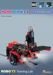
ROBO TX Training Lab<br />
You can create a subprogram for "going around a corner." This allows the main program to remain clearer.<br />
You certainly already have the solution for the task in your head. But just in case, here is a suggestion<br />
from us again:<br />
Always the same, but not exactly?<br />
As you have certainly noticed, the repeating accuracy of the robot is still capable of improvement. Even if it carries<br />
out the same task several times, the result is not always the same. This is due to various reasons. One of these is<br />
that both motors do not rotate at exactly the same speed. For example, the gearbox for one motor can run with more<br />
difficulty than that of the other motor. And because both motors are operated with the same voltage (nine volts) then<br />
one motor rotates slower than the other one. Since in the past, we have controlled our robot through waiting times,<br />
perhaps one wheel has rotated farther during this time than the other one.<br />
Thus, the solution would be to have both motors rotate at exactly the same speed. And it is precisely this that can be<br />
very simply done with the encoder motors.<br />
Task 4: Use Encoder Motors<br />
• Repeat the last three tasks and instead of the normal motor output and waiting time elements use the<br />
encoder motor elements. How you use these is described in the ROBO Pro online help in chapter 11.6.<br />
Programing Tip<br />
• With the encoder motor element, you can control both motors at the same time with a program item. Using the<br />
distance, you insure that each motor only rotates as far as it is supposed to.<br />
•<br />
You can open the solution suggestions as usual by clicking on the symbols on<br />
the right.<br />
For counting the pulses at the fast counting inputs, C1-C4, you do not need an additional<br />
program item in ROBO Pro. The counting input, C1, is automatically assigned internally to the motor, M1, M2<br />
belongs to C2 and so forth.<br />
Note!<br />
If your model does not move straight ahead in spite of the use of the encoder motor elements then the cause may be<br />
in the model itself. For example, if a hub nut, which transmits the force from the axle to the wheels, is not tightened<br />
enough then the axle slips and the model moves in a curve although the motors rotate at the same speed. So tighten<br />
the hub nuts very firmly.<br />
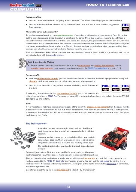
The Trail Searcher<br />
Your robot can now move straight ahead and turn. And in the<br />
past, it only makes this precisely as you prescribe for it with the<br />
program.<br />
However, a robot is supposed to actually be able to react as independently<br />
as possible. That's why we now want to give it something<br />
that it can react to: a black line as a marking on the floor.<br />
The goal is that the robot searches for the black line and moves<br />
along it.<br />
But one thing at a time. First, you must modify the basic model so it becomes<br />
the trail searcher. How this is done is found naturally in the assembly instructions.<br />
After you have finished modifying the model, you should use the interface test to check if all components are correctly<br />
connected to the ROBO TX Controller and function properly. You can test the trail sensor by holding it over<br />
the black trail of the course and moving it sideways. The signals at the inputs, to which the trail sensor is connected,<br />
should change due to this.<br />
Don't forget to set the inputs in the interface test to "digital 10V (trail sensor)."