technical data & service manual split system air conditioner
technical data & service manual split system air conditioner
technical data & service manual split system air conditioner

Create successful ePaper yourself
Turn your PDF publications into a flip-book with our unique Google optimized e-Paper software.
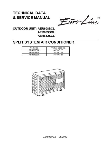
TECHNICAL DATA<br />
& SERVICE MANUAL<br />
OUTDOOR UNIT: AER608SCL<br />
AER609SCL<br />
AER612SCL<br />
SPLIT SYSTEM AIR CONDITIONER<br />
Model No. Product Code No.<br />
AER608SCL 387007127<br />
AER609SCL 387007128<br />
AER612SCL 387007129<br />
0.8180.272.0 05/2002<br />
®
IMPORTANT!<br />
Please read before installation<br />
This <strong>air</strong> conditioning <strong>system</strong> meets strict safety and operating<br />
standards.<br />
For the installer or <strong>service</strong> person, it is important to install or<br />
<strong>service</strong> the <strong>system</strong> so that it operates safely and efficiently.<br />
For safe installation and trouble-free operation, you must:<br />
• Carefully read this instruction booklet before beginning.<br />
• Follow each installation or rep<strong>air</strong> step exactly as shown.<br />
• Observe all local, state and national electrical codes.<br />
• Pay close attention to all warning and caution notices given in<br />
this <strong>manual</strong>.<br />
•The unit must be supplied with a dedicated electrical line.<br />
WARNING<br />
This symbol refers to a hazard or unsafe practice which can result<br />
in severe personal injury or death.<br />
CAUTION<br />
This symbol refers to a hazard or unsafe practice which can result<br />
in personal injury or product or property damage.<br />
If necessary, get help<br />
These instructions are all you need for most installation sites and<br />
maintenance conditions.<br />
If you require help for a special problem, contact our sale/<strong>service</strong><br />
outlet or your certified dealer for additional instructions.<br />
In case of improper installation<br />
The manufacturer shall in no way be responsible for improper<br />
installation or maintenance <strong>service</strong>, including failure to follow the<br />
instructions in this document.<br />
SPECIAL PRECAUTIONS<br />
• During installation, connect before the refrigerant <strong>system</strong> and<br />
then the wiring one; proceed in the reverse orden when removing<br />
the units.<br />
WARNING When wiring<br />
ELECTRICAL SHOCK CAN CAUSE SEVERE<br />
PERSONAL INJURY OR DEATH. ONLY A QUALIFIED,<br />
EXPERIENCED ELECTRICIANS SHOULD ATTEMPT<br />
TO WIRE THIS SYSTEM.<br />
• Do not supply power to the unit until all wiring and tubing are<br />
completed or reconnected and checked, to ensure the grounding.<br />
• Highly dangerous electrical voltages are used in this <strong>system</strong>.<br />
Carefully refer to the wiring diagram and these instructions when<br />
wiring.<br />
Improper connections and inadequate grounding can cause<br />
accidental injury and death.<br />
2<br />
• Ground the unit following local electrical codes.<br />
• The Yellow/Green wire cannot be used for any connection<br />
different from the ground connection.<br />
• Connect all wiring tightly. Loose wiring may cause overheating<br />
at connection points and a possible fire hazard.<br />
• Do not allow wiring to touch the refrigerant tubing, compressor,<br />
or any moving parts of the fan.<br />
• Do not use multi-core cable when wiring the power supply and<br />
control lines. Use separate cables for each type of line.<br />
When transporting<br />
Be careful when picking up and moving the indoor and outdoor<br />
units. Get a partner to help, and bend your knees when lifting to<br />
reduce strain on your back. Sharp edges or thin aluminium fins on<br />
the <strong>air</strong> <strong>conditioner</strong> can cut your fingers.<br />
When installing...<br />
... In a ceiling or wall<br />
Make sure the ceiling/wall is strong enough to hold the unit-weight.<br />
It may be necessary to build a strong wooden or metal frame to<br />
provide added support.<br />
... In a room<br />
Properly insulate any tubing run inside a room to prevent<br />
"sweating", which can cause dripping and water damage to walls<br />
and floors.<br />
... In moist or uneven locations<br />
Use a raised concrete base to provide a solid level foundation for<br />
the outdoor unit.<br />
This prevents damage and abnormal vibrations.<br />
... In area with strong winds<br />
Securely anchor the outdoor unit down with bolts and a metal<br />
frame. Provide a suitable <strong>air</strong> baffle.<br />
... In a snowy area (for heat pump-type <strong>system</strong>s)<br />
Install the outdoor unit on a raised platform that is higher than<br />
drifting snow. Provide snow vents.<br />
When connecting refrigerant tubing<br />
• Keep all tubing runs as short as possible.<br />
• Use the flare method for connecting tubing.<br />
• Apply refrigerant lubricant to the matching surfaces of the flare<br />
and union tubes before connecting them; screw by hand and<br />
then tighten the nut with a torque wrench for a leak-free<br />
connection.<br />
• Check carefully for leaks before starting the test run.<br />
NOTE:<br />
Depending on the <strong>system</strong> type, liquid and gas lines may be either<br />
narrow or wide. Therefore, to avoid confusion, the refrigerant<br />
tubing for your particular model is specified as narrow tube for<br />
liquid, wide tube for gas.<br />
When servicing<br />
• Turn the power OFF at the main power board before opening<br />
the unit to check or rep<strong>air</strong> electrical parts and wiring.<br />
• Keep your fingers and clothing away from any moving parts.<br />
• Clean up the site after the work, remembering to check that no<br />
metal scraps or bits of wiring have been left inside the unit being<br />
<strong>service</strong>d.<br />
• Ventilate the room during the installation or testng the refrigeration<br />
<strong>system</strong>; make sure that, after the installation, no gas leaks are<br />
present, because this could produce toxic gas and dangerous<br />
if in contact with flames or heat-sources.
Table of Contents<br />
Page<br />
1. OPERATING RANGE 4<br />
2. SPECIFICATIONS 5<br />
2-1 Unit specifications 5<br />
2-2 Major Component specifications 8<br />
2-3 Other Component specifications 11<br />
3. DIMENSIONAL DATA 12<br />
4. REFRIGERANT FLOW DIAGRAM 13<br />
5. PERFORMANCE DATA 14<br />
5-1 Performance Charts 14<br />
5-2 Cooling Capacity 17<br />
6. ELECTRICAL DATA 20<br />
6-1 Electrical characteristics 20<br />
6-2 Electric Wiring Diagram 21<br />
6-3 System Wiring Diagram 21<br />
3
1. OPERATING RANGE<br />
Cooling<br />
Temperature Indoor Air Intake Temp. Outdoor Air Intake Temp.<br />
Maximum<br />
Minimum<br />
32°C D.B. / 23°C W.B.<br />
19°C D.B. / 14°C W.B.<br />
4<br />
43°C D.B.<br />
-15°C D.B.
2. SPECIFICATIONS<br />
2-1 Unit Specifications<br />
AER608SCL<br />
Power source<br />
Voltage rating<br />
Performance * AWR608CL<br />
Capacity kW<br />
BTU/h<br />
Air circulation (High) m³/h<br />
Moisture removal (High) Liters/h<br />
Electrical Rating<br />
Available voltage range V<br />
Running amperes A<br />
Power input W<br />
Power factor %<br />
C.O.P. W/W<br />
Compressor locked rotor amperes A<br />
Features<br />
Fan speed<br />
Compressor<br />
Refrigerant / Amount charged at shipment g<br />
Refrigerant control<br />
Operation Sound Hi dB-A<br />
Refrigerant tubing connections<br />
Max. allowable tubing length at shipment m<br />
Refrigerant Narrow tube mm(in.)<br />
tube diameter Wide tube mm(in.)<br />
Dimensions & Weight<br />
Unit dimensions Height mm<br />
Width mm<br />
Depth mm<br />
Package dimensions Height mm<br />
Width mm<br />
Depth mm<br />
Weight Net kg<br />
Shipping kg<br />
Shipping volume m 3<br />
Remarks:<br />
Rating conditions are:<br />
Cooling: Indoor <strong>air</strong> temperature 27°C D.B. / 19°C W.B.<br />
Outdoor <strong>air</strong> temperature 35°C D.B. / 24°C W.B.<br />
* For other INDOOR UNITS' MODELS, please refer to catalogue<br />
5<br />
220 - 240 V ~ 50 Hz<br />
230 V<br />
Cooling<br />
1,90<br />
6485<br />
430<br />
0,40<br />
Cooling<br />
198 ~ 264<br />
3,20<br />
680<br />
92<br />
2,8<br />
17<br />
1(Hi)<br />
Rotary (Hermetic)<br />
R407C / 730<br />
Capillary tube<br />
57<br />
Flare type<br />
7.5<br />
6,35 (1/4)<br />
9,52 (3/8)<br />
540<br />
700<br />
265<br />
568<br />
815<br />
343<br />
34<br />
37<br />
0,16<br />
DATA SUBJECT TO CHANGE WITHOUT NOTICE
AER609SCL<br />
Power source<br />
Voltage rating<br />
Performance * AWR609CL<br />
Capacity kW<br />
BTU/h<br />
Air circulation (High) m³/h<br />
Moisture removal (High) Liters/h<br />
Electrical Rating<br />
Available voltage range V<br />
Running amperes A<br />
Power input W<br />
Power factor %<br />
C.O.P. W/W<br />
Compressor locked rotor amperes A<br />
Features<br />
Fan speed<br />
Compressor<br />
Refrigerant / Amount charged at shipment g<br />
Refrigerant control<br />
Operation Sound Hi dB-A<br />
Refrigerant tubing connections<br />
Max. allowable tubing length at shipment m<br />
Refrigerant Narrow tube mm(in.)<br />
tube diameter Wide tube mm(in.)<br />
Remarks:<br />
Rating conditions are:<br />
Cooling: Indoor <strong>air</strong> temperature 27°C D.B. / 19°C W.B.<br />
Outdoor <strong>air</strong> temperature 35°C D.B. / 24°C W.B.<br />
* For other INDOOR UNITS' MODELS, please refer to catalogue<br />
220 - 240 V ~ 50 Hz<br />
230 V<br />
Cooling<br />
2,60<br />
8874<br />
450<br />
0,80<br />
Cooling<br />
198 ~ 264<br />
4,40<br />
990<br />
98<br />
2,6<br />
23<br />
1(Hi)<br />
Rotary (Hermetic)<br />
R407C / 800<br />
Capillary tube<br />
57<br />
Flare type<br />
7.5<br />
6,35 (1/4)<br />
9,52 (3/8)<br />
Dimensions & Weight<br />
Unit dimensions Height mm<br />
Width mm<br />
Depth mm<br />
Package dimensions Height mm<br />
Width mm<br />
Depth mm<br />
Weight Net kg<br />
Shipping kg<br />
Shipping volume m 3<br />
540<br />
700<br />
265<br />
568<br />
815<br />
343<br />
36<br />
39<br />
0,16<br />
DATA SUBJECT TO CHANGE WITHOUT NOTICE<br />
6
AER612SCL<br />
Power source<br />
Voltage rating<br />
Performance * AWR612CL<br />
Capacity kW<br />
BTU/h<br />
Air circulation (High) m³/h<br />
Moisture removal (High) Liters/h<br />
Electrical Rating<br />
Available voltage range V<br />
Running amperes A<br />
Power input W<br />
Power factor %<br />
C.O.P. W/W<br />
Compressor locked rotor amperes A<br />
Features<br />
Fan speed<br />
Compressor<br />
Refrigerant / Amount charged at shipment g<br />
Refrigerant control<br />
Operation Sound Hi dB-A<br />
Refrigerant tubing connections<br />
Max. allowable tubing length at shipment m<br />
Refrigerant Narrow tube mm(in.)<br />
tube diameter Wide tube mm(in.)<br />
Remarks:<br />
Rating conditions are:<br />
Cooling: Indoor <strong>air</strong> temperature 27°C D.B. / 19°C W.B.<br />
Outdoor <strong>air</strong> temperature 35°C D.B. / 24°C W.B.<br />
* For other INDOOR UNITS' MODELS, please refer to catalogue<br />
220 - 240 V ~ 50 Hz<br />
230 V<br />
Cooling<br />
3,40<br />
11604<br />
470<br />
1,50<br />
Cooling<br />
198 ~ 264<br />
6,30<br />
1380<br />
95<br />
2,5<br />
33<br />
1(Hi)<br />
Rotary (Hermetic)<br />
R407C / 750<br />
Capillary tube<br />
59<br />
Flare type<br />
7.5<br />
6,35 (1/4)<br />
12,7 (1/2)<br />
Dimensions & Weight<br />
Unit dimensions Height mm<br />
Width mm<br />
Depth mm<br />
Package dimensions Height mm<br />
Width mm<br />
Depth mm<br />
Weight Net kg<br />
Shipping kg<br />
Shipping volume m 3<br />
540<br />
700<br />
265<br />
568<br />
815<br />
343<br />
37<br />
40<br />
0,16<br />
DATA SUBJECT TO CHANGE WITHOUT NOTICE<br />
7
2-2 Major Component Specifications<br />
Outdoor Unit: AER608SCL<br />
Controller PCB<br />
Part No.<br />
Control circuit fuse<br />
Compressor<br />
Type<br />
Compressor model<br />
Nominal output W<br />
Compressor oil…Amount cc<br />
Coil resistance (Ambient temp. 25°C) Ω<br />
Overload relay<br />
Safety devices Type<br />
Operating Temp. Open °C<br />
Close °C<br />
Operating amp. (Ambient temp. 25°C)<br />
Run capacitor µF<br />
VAC<br />
Fan & Fan Motor<br />
Type<br />
Q'ty ……. Dia.<br />
Fan motor model…Q'ty<br />
No. Of poles…rpm (230 V, High)<br />
Nominal output W<br />
Coil resistance (Ambient temp. 25 °C ) Ω<br />
Safety devices Type<br />
Operating temp. Open °C<br />
Close °C<br />
Run capacitor µF<br />
VAC<br />
Heat Exch. Coil<br />
Coil<br />
Rows<br />
Fin pitch mm<br />
Face area m 2<br />
External Finish<br />
8<br />
POW-CL128E<br />
250 V 3,15 A<br />
Rotary (Hermetic)<br />
802 060 35B C-1RN60H5C<br />
600<br />
FV68S…350<br />
C-R: 4,66<br />
C-S: 8,89<br />
External (OLR A) External (OLR T)<br />
MRA 38072-3229<br />
CS-7C115<br />
145 ± 5<br />
115 ± 3<br />
69 ± 11<br />
95 ± 5<br />
Trip in 6 to 16 s at 13 A<br />
//<br />
17,5<br />
450<br />
Propeller<br />
1…. Ø 370<br />
K35410-M01846…1<br />
4…782<br />
19<br />
BLK-WHT: 211÷242<br />
WHT-VLT: 244÷281<br />
VLT-YEL: 83,5÷96,1<br />
BLK-PNK: 41,7÷48,0<br />
Thermal protector<br />
150 ± 10<br />
Automatic<br />
1,5<br />
450<br />
Aluminium plate fin / Copper tube<br />
1<br />
1,3<br />
0,353<br />
Acrylic baked-on enamel finish<br />
DATA SUBJECT TO CHANGE WITHOUT NOTICE
Outdoor Unit: AER609SCL<br />
Controller PCB<br />
Part No.<br />
Control circuit fuse<br />
Compressor<br />
Type<br />
Compressor model<br />
Nominal output W<br />
Compressor oil…Amount cc.<br />
Coil resistance (Ambient temp. 25°C) Ω<br />
Overload relay<br />
Safety devices Type<br />
Operating Temp. Open °C<br />
Close °C<br />
Run capacitor µF<br />
VAC<br />
Fan & Fan Motor<br />
Type<br />
Q'ty ……. Dia.<br />
Fan motor model…Q'ty<br />
No. Of poles…rpm (230 V, High)<br />
Nominal output W<br />
Coil resistance (Ambient temp. 25 °C ) Ω<br />
Safety devices Type<br />
Operating temp. Open °C<br />
Close °C<br />
Run capacitor µF<br />
VAC<br />
Heat Exch. Coil<br />
Coil<br />
Rows<br />
Fin pitch mm<br />
Face area m 2<br />
External Finish<br />
9<br />
POW-CL128E<br />
250 V 3,15 A<br />
Rotary (Hermetic)<br />
802 282 45G C-RN80H5A<br />
800<br />
FV68S…470<br />
C-R: 3,07<br />
C-S: 7,97<br />
External (OLR A) External (OLR T)<br />
MRA 38066-3229 CS-7C115<br />
145 ± 5<br />
115 ± 3<br />
69 ± 11 95 ± 5<br />
Trip in 6 to 16 s at 18 A //<br />
22,5<br />
450<br />
Propeller<br />
1…. Ø 370<br />
K35410-M01846…1<br />
4…782<br />
19<br />
BLK-WHT: 211÷242<br />
WHT-VLT: 244÷281<br />
VLT-YEL: 83,5÷96,1<br />
BLK-PNK: 41,7÷48,0<br />
Thermal protector<br />
150 ± 10<br />
Automatic<br />
1,5<br />
450<br />
Aluminium plate fin / Copper tube<br />
1<br />
1,3<br />
0,353<br />
Acrylic baked-on enamel finish
Outdoor Unit: AER612SCL<br />
Controller PCB<br />
Part No.<br />
Control circuit fuse<br />
Compressor<br />
Type<br />
Compressor model<br />
Nominal output W<br />
Compressor oil…Amount cc.<br />
Coil resistance (Ambient temp. 25°C) Ω<br />
Overload relay<br />
Safety devices Type<br />
Operating Temp. Open °C<br />
Close °C<br />
Run capacitor µF<br />
VAC<br />
Fan & Fan Motor<br />
Type<br />
Q'ty ……. Dia.<br />
Fan motor model…Q'ty<br />
No. Of poles…rpm (230 V, High)<br />
Nominal output W<br />
Coil resistance (Ambient temp. 25 °C ) Ω<br />
Safety devices Type<br />
Operating temp. Open °C<br />
Close °C<br />
Run capacitor µF<br />
VAC<br />
Heat Exch. Coil<br />
Coil<br />
Rows<br />
Fin pitch mm<br />
Face area m 2<br />
POW-CL128E<br />
250 V 3,15 A<br />
Rotary (Hermetic)<br />
802 356 45B C-RN110H5B<br />
1100<br />
FV68S…520<br />
C-R: 1,962<br />
C-S: 5,38<br />
External (OLR A) External (OLR T)<br />
MRA 38065-3229 CS-7C115<br />
145 ± 5 115 ± 3<br />
69 ± 11 95 ± 5<br />
Trip in 6 to 16 s at 21 A //<br />
25<br />
450<br />
Propeller<br />
1…. Ø 370<br />
K35410-M01846…1<br />
4…819<br />
22<br />
BLK-WHT: 211÷242<br />
WHT-VLT: 244÷281<br />
VLT-YEL: 83,5÷96,1<br />
BLK-PNK: 41,7÷48,0<br />
Thermal protector<br />
150 ± 10<br />
Automatic<br />
2<br />
450<br />
Aluminium plate fin / Copper tube<br />
1<br />
1,3<br />
0,353<br />
External Finish Acrylic baked-on enamel finish<br />
10
2-3 Other Component Specifications<br />
Outdoor Unit: AER608SCL<br />
AER609SCL<br />
AER612SCL<br />
Transformer<br />
Type<br />
Rating Primary<br />
Secondary<br />
Capacity<br />
Coil resistance (at 21°C) Ω<br />
Thermal cut-off temp. °C<br />
Thermistor<br />
Type<br />
Resistance kΩ<br />
11<br />
ATR-J105<br />
230 V ~ 50/60 Hz<br />
19 V 0,526 A<br />
10 VA<br />
Primary (WHT-WHT): 205 ± 10%<br />
Secondary (BRN-BRN): 2,0 ± 10%<br />
150<br />
PBC-41E-S14 or PBC-41E-S4<br />
-20 °C 40,1 ± 5% 20 °C 6,5 ± 5%<br />
-10 °C 24,4 ± 5% 30 °C 4,4 ± 5%<br />
0 °C 15,3 ± 5% 40 °C 3,0 ± 5%<br />
10 °C 9,9 ± 5% 50 °C 2,1 ± 5%
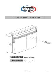
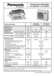
3. DIMENSIONAL DATA<br />
4 – ø12 holes<br />
470<br />
Air intake<br />
Air discharge<br />
700<br />
116<br />
12<br />
294<br />
15<br />
320<br />
540<br />
10<br />
Wide tube <strong>service</strong> valve<br />
ø9.52 (3/8")<br />
ø12.7 (1/2")<br />
Narrow tube <strong>service</strong> valve<br />
ø6.35 (1/4")<br />
255<br />
170<br />
7000/9000 BTU/h<br />
12000 BTU/h<br />
103 57<br />
Unit : mm
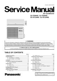
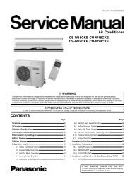
4. REFRIGERANT FLOW DIAGRAM<br />
Indoor Unit: Outdoor Unit: AER608SCL<br />
AER609SCL<br />
Indoor Unit Outdoor Unit<br />
Evaporator<br />
Wide tube<br />
O.D.<br />
ø9.52 mm<br />
(3/8 ")<br />
Narrow tube<br />
O.D.<br />
ø6.35 mm<br />
(1/4")<br />
Wide tube<br />
<strong>service</strong><br />
valve<br />
Narrow<br />
tube<br />
<strong>service</strong><br />
valve<br />
Muffler<br />
Capillary tube<br />
Accumulator<br />
Indoor Unit: Outdoor Unit: AER612SCL<br />
Indoor Unit Outdoor Unit<br />
Evaporator<br />
Insulation of Refrigerant Tubing<br />
IMPORTANT<br />
Wide tube<br />
O.D.<br />
ø12.7 mm<br />
(1/2 ")<br />
Narrow tube<br />
O.D.<br />
ø6.35 mm<br />
(1/4")<br />
Wide tube<br />
<strong>service</strong><br />
valve<br />
Narrow<br />
tube<br />
<strong>service</strong><br />
valve<br />
Because capillary tubing is used in the outdoor unit, both the<br />
wide and narrow tubes of this <strong>air</strong> <strong>conditioner</strong> become cold. To<br />
prevent heat loss and wet floors due to dripping of<br />
condensation, both tubes must be well insulated with a<br />
proper insulation material. The thickness of the insulation<br />
should be a min. 8 mm.<br />
CAUTION<br />
After a tube has been insulated,<br />
never try to bend it into a narrow<br />
curve because it can cause the tube<br />
to break or crack.<br />
13<br />
Muffler<br />
Capillary tube<br />
Thickness:<br />
Min. 8 mm<br />
Wide tube<br />
Accumulator<br />
Condenser<br />
Condenser<br />
Compressor<br />
Compressor<br />
Insulation<br />
Narrow tube<br />
Thickness:<br />
Min. 8 mm
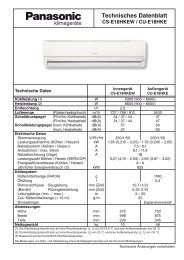
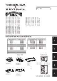
5. PERFORMANCE DATA<br />
5-1 Performance charts<br />
AER608SCL<br />
� Cooling Characteristics<br />
Notes:<br />
Operating current (A)<br />
Low pressure at wide tube <strong>service</strong> valve MPa<br />
0,90<br />
0,80<br />
0,70<br />
0,60<br />
0,50<br />
0,40<br />
0,30<br />
0,20<br />
0,10<br />
Points of Rating condition<br />
Data referred to indoor unit AWR608CL<br />
6<br />
5<br />
4<br />
3<br />
2<br />
Indoor inlet <strong>air</strong><br />
D.B. (°C)<br />
1<br />
20 25 30 35 40 45<br />
Outdoor inlet <strong>air</strong> D.B. temp. (°C)<br />
Indoor inlet <strong>air</strong><br />
D.B. (°C)<br />
0,00<br />
20 25 30 35 40 45<br />
Outdoor inlet <strong>air</strong> D.B. (°C)<br />
14<br />
32<br />
27<br />
19<br />
32<br />
27<br />
19
AER609SCL<br />
� Cooling Characteristics<br />
Notes:<br />
Operating current (A)<br />
Low pressure at wide tube <strong>service</strong> valve MPa<br />
0,90<br />
0,80<br />
0,70<br />
0,60<br />
0,50<br />
0,40<br />
0,30<br />
0,20<br />
0,10<br />
Points of Rating condition<br />
Data referred to indoor unit AWR609CL<br />
6<br />
5<br />
4<br />
3<br />
2<br />
Indoor inlet <strong>air</strong><br />
D.B. (°C)<br />
1<br />
20 25 30 35 40 45<br />
Outdoor inlet <strong>air</strong> D.B. temp. (°C)<br />
Indoor inlet <strong>air</strong><br />
D.B. (°C)<br />
0,00<br />
20 25 30 35 40 45<br />
Outdoor inlet <strong>air</strong> D.B. (°C)<br />
15<br />
32<br />
27<br />
19<br />
32<br />
27<br />
19
AER612SCL<br />
� Cooling Characteristics<br />
Notes:<br />
Operating current (A)<br />
Points of Rating condition<br />
Data referred to indoor unit AWR612CL<br />
10<br />
9<br />
8<br />
7<br />
6<br />
5<br />
4<br />
3<br />
2<br />
Indoor inlet <strong>air</strong><br />
D.B. (°C)<br />
1<br />
20 25 30 35 40 45<br />
Low pressure at wide tube <strong>service</strong> valve MPa<br />
0,90<br />
0,80<br />
0,70<br />
0,60<br />
0,50<br />
0,40<br />
0,30<br />
0,20<br />
0,10<br />
Outdoor inlet <strong>air</strong> D.B. temp. (°C)<br />
Indoor inlet <strong>air</strong><br />
D.B. (°C)<br />
0,00<br />
20 25 30 35 40 45<br />
Outdoor inlet <strong>air</strong> D.B. (°C)<br />
16<br />
32<br />
27<br />
19<br />
32<br />
27<br />
19
5-2 Cooling Capacity<br />
OUTDOOR UNIT: AER608SCL<br />
220 - 240 V ~ 50 Hz<br />
RATING CAPACITY 1,90 kW moisture removal 0,4 l/h<br />
COMP. POWER INPUT 0,586 kW max comp input 0,666 kW<br />
AIR FLOW RATE 430 m³/h<br />
EVAPORATOR<br />
CONDENSER<br />
ENT.TEMP. °C<br />
OUTDOOR AMBIENT TEMP. °C<br />
W.B. D.B. 20 25 30 35 40 43<br />
TC 1,92 1,80 1,75 1,66 1,56 1,44<br />
CM 0,48 0,51 0,53 0,55 0,57 0,60<br />
21 SHC 1,33 1,23 1,21 1,17 1,12 1,06<br />
23 SHC 1,51 1,40 1,37 1,33 1,28 1,22<br />
15 25 SHC 1,67 1,56 1,53 1,49 1,44 1,38<br />
27 SHC 1,84 1,72 1,69 1,65 1,56 1,44<br />
29 SHC 1,92 1,80 1,75 1,66 1,56 1,44<br />
31 SHC 1,92 1,80 1,75 1,66 1,56 1,44<br />
TC 2,06 1,95 1,88 1,78 1,68 1,54<br />
CM 0,50 0,52 0,55 0,57 0,59 0,61<br />
21 SHC 1,15 1,08 1,05 1,01 0,96 0,90<br />
23 SHC 1,32 1,24 1,21 1,16 1,12 1,06<br />
17 25 SHC 1,49 1,41 1,37 1,33 1,28 1,21<br />
27 SHC 1,67 1,57 1,52 1,48 1,43 1,38<br />
29 SHC 1,84 1,73 1,69 1,64 1,59 1,53<br />
31 SHC 2,01 1,90 1,84 1,78 1,68 1,54<br />
TC 2,19 2,07 2,00 1,90 1,78 1,64<br />
CM 0,52 0,54 0,56 0,59 0,61 0,63<br />
21 SHC 0,96 0,90 0,88 0,83 0,78 0,73<br />
23 SHC 1,14 1,06 1,04 1,00 0,95 0,89<br />
19 25 SHC 1,31 1,22 1,19 1,15 1,11 1,05<br />
27 SHC 1,48 1,38 1,35 1,62 1,26 1,21<br />
29 SHC 1,65 1,53 1,51 1,47 1,43 1,36<br />
31 SHC 1,82 1,69 1,67 1,63 1,58 1,52<br />
TC 2,30 2,19 2,11 2,02 1,89 1,74<br />
CM 0,54 0,56 0,58 0,61 0,63 0,65<br />
23 SHC 0,94 0,89 0,86 0,82 0,77 0,71<br />
21 25 SHC 1,12 1,05 1,02 0,98 0,93 0,88<br />
27 SHC 1,29 1,20 1,18 1,14 1,09 1,03<br />
29 SHC 1,46 1,36 1,34 1,30 1,25 1,19<br />
31 SHC 1,63 1,52 1,50 1,46 1,41 1,35<br />
TC 2,45 2,31 2,24 2,11 1,98 1,84<br />
CM 0,56 0,58 0,60 0,62 0,65 0,67<br />
23 25 SHC 0,92 0,87 0,84 0,79 0,74 0,69<br />
27 SHC 1,09 1,02 1,00 0,95 0,90 0,85<br />
29 SHC 1,27 1,17 1,16 1,11 1,06 1,01<br />
31 SHC 1,44 1,33 1,32 1,27 1,22 1,17<br />
TC: TOTAL COOLING CAPACITY kW<br />
SHC: SENSIBLE HEAT CAPACITY kW<br />
CM: COMPRESSOR INPUT kW<br />
RATING CONDITIONS<br />
Cooling: Indoor <strong>air</strong> temperature 27°C D.B. / 19°C W.B.<br />
Outdoor <strong>air</strong> temperature 35°C D.B. / 24°C W.B.<br />
NOTE: Data referred to indoor unit AWR608CL<br />
17
OUTDOOR UNIT: AER609SCL<br />
220 - 240 V ~ 50 Hz<br />
RATING CAPACITY 2,60 kW moisture removal 0,8 l/h<br />
COMP. POWER INPUT 0,89 kW max comp input 1,02 kW<br />
AIR FLOW RATE 450 m³/h<br />
EVAPORATOR<br />
CONDENSER<br />
ENT.TEMP. °C<br />
OUTDOOR AMBIENT TEMP. °C<br />
W.B. D.B. 20 25 30 35 40 43<br />
TC 2,63 2,46 2,39 2,28 2,14 1,97<br />
CM 0,73 0,76 0,80 0,83 0,86 0,89<br />
21 SHC 1,82 1,69 1,66 1,60 1,53 1,45<br />
23 SHC 2,06 1,91 1,88 1,82 1,75 1,67<br />
15 25 SHC 2,29 2,13 2,09 2,03 1,97 1,89<br />
27 SHC 2,52 2,36 2,31 2,26 2,14 1,97<br />
29 SHC 2,63 2,46 2,39 2,28 2,14 1,97<br />
31 SHC 2,63 2,46 2,39 2,28 2,14 1,97<br />
TC 2,81 2,67 2,57 2,44 2,29 2,11<br />
CM 0,76 0,80 0,83 0,86 0,89 0,93<br />
21 SHC 1,57 1,48 1,44 1,38 1,31 1,23<br />
23 SHC 1,81 1,70 1,65 1,59 1,53 1,45<br />
17 25 SHC 2,04 1,93 1,87 1,81 1,75 1,66<br />
27 SHC 2,28 2,15 2,09 2,03 1,96 1,88<br />
29 SHC 2,52 2,37 2,31 2,25 2,18 2,10<br />
31 SHC 2,75 2,59 2,52 2,44 2,29 2,11<br />
TC 2,99 2,83 2,73 2,60 2,44 2,25<br />
CM 0,80 0,83 0,86 0,89 0,93 0,96<br />
21 SHC 1,32 1,24 1,20 1,14 1,07 0,99<br />
23 SHC 1,56 1,46 1,42 1,36 1,29 1,22<br />
19 25 SHC 1,79 1,67 1,63 1,58 1,51 1,43<br />
27 SHC 2,02 1,88 1,85 2,04 1,73 1,65<br />
29 SHC 2,26 2,09 2,07 2,01 1,95 1,87<br />
31 SHC 2,49 2,31 2,29 2,23 2,16 2,09<br />
TC 3,15 3,00 2,89 2,76 2,59 2,39<br />
CM 0,83 0,86 0,89 0,93 0,96 0,99<br />
23 SHC 1,29 1,22 1,18 1,12 1,06 0,98<br />
21 25 SHC 1,53 1,43 1,40 1,35 1,28 1,20<br />
27 SHC 1,76 1,65 1,62 1,56 1,50 1,41<br />
29 SHC 2,00 1,86 1,83 1,78 1,71 1,63<br />
31 SHC 2,22 2,08 2,05 2,00 1,93 1,85<br />
TC 3,35 3,16 3,06 2,89 2,71 2,52<br />
CM 0,86 0,89 0,93 0,96 0,99 1,02<br />
23 25 SHC 1,26 1,19 1,15 1,09 1,02 0,95<br />
27 SHC 1,50 1,39 1,36 1,30 1,23 1,16<br />
29 SHC 1,73 1,60 1,58 1,52 1,45 1,38<br />
31 SHC 1,97 1,83 1,80 1,74 1,67 1,61<br />
TC: TOTAL COOLING CAPACITY kW<br />
SHC: SENSIBLE HEAT CAPACITY kW<br />
CM: COMPRESSOR INPUT kW<br />
RATING CONDITIONS<br />
Cooling: Indoor <strong>air</strong> temperature 27°C D.B. / 19°C W.B.<br />
Outdoor <strong>air</strong> temperature 35°C D.B. / 24°C W.B.<br />
NOTE: Data referred to indoor unit AWR609CL<br />
18
OUTDOOR UNIT: AER612SCL<br />
220 - 240 V ~ 50 Hz<br />
RATING CAPACITY 3,40 kW moisture removal 1,5 l/h<br />
COMP. POWER INPUT 1,271 kW max comp input 1,491 kW<br />
AIR FLOW RATE 470 m³/h<br />
EVAPORATOR<br />
CONDENSER<br />
ENT.TEMP. °C<br />
OUTDOOR AMBIENT TEMP. °C<br />
W.B. D.B. 20 25 30 35 40 43<br />
TC 3,43 3,22 3,13 2,98 2,79 2,58<br />
CM 0,98 1,05 1,12 1,19 1,27 1,34<br />
21 SHC 2,38 2,21 2,17 2,09 2,00 1,90<br />
23 SHC 2,69 2,50 2,45 2,38 2,29 2,19<br />
15 25 SHC 2,99 2,79 2,73 2,66 2,57 2,47<br />
27 SHC 3,30 3,08 3,02 2,95 2,79 2,58<br />
29 SHC 3,43 3,22 3,13 2,98 2,79 2,58<br />
31 SHC 3,43 3,22 3,13 2,98 2,79 2,58<br />
TC 3,68 3,49 3,36 3,19 3,00 2,76<br />
CM 1,02 1,09 1,16 1,23 1,30 1,38<br />
21 SHC 2,05 1,93 1,88 1,80 1,71 1,60<br />
23 SHC 2,36 2,22 2,16 2,08 2,00 1,89<br />
17 25 SHC 2,67 2,52 2,45 2,37 2,28 2,17<br />
27 SHC 2,98 2,81 2,73 2,65 2,56 2,46<br />
29 SHC 3,29 3,10 3,02 2,94 2,85 2,74<br />
31 SHC 3,59 3,39 3,30 3,19 3,00 2,76<br />
TC 3,91 3,70 3,57 3,40 3,19 2,94<br />
CM 1,06 1,13 1,20 1,27 1,34 1,41<br />
21 SHC 1,73 1,62 1,57 1,49 1,40 1,30<br />
23 SHC 2,04 1,90 1,86 1,78 1,69 1,59<br />
19 25 SHC 2,35 2,18 2,14 2,06 1,98 1,87<br />
27 SHC 2,64 2,46 2,42 2,35 2,26 2,16<br />
29 SHC 2,95 2,73 2,71 2,63 2,55 2,44<br />
31 SHC 3,26 3,02 2,99 2,92 2,83 2,73<br />
TC 4,11 3,92 3,78 3,61 3,39 3,12<br />
CM 1,08 1,16 1,23 1,30 1,38 1,45<br />
23 SHC 1,69 1,60 1,54 1,47 1,38 1,28<br />
21 25 SHC 2,00 1,87 1,83 1,76 1,67 1,57<br />
27 SHC 2,31 2,15 2,11 2,04 1,96 1,85<br />
29 SHC 2,62 2,43 2,39 2,33 2,24 2,14<br />
31 SHC 2,91 2,71 2,68 2,61 2,53 2,42<br />
TC 4,39 4,14 4,01 3,78 3,54 3,30<br />
CM 1,11 1,19 1,26 1,34 1,41 1,49<br />
23 25 SHC 1,65 1,55 1,50 1,42 1,33 1,24<br />
27 SHC 1,96 1,82 1,78 1,70 1,61 1,52<br />
29 SHC 2,27 2,09 2,07 1,99 1,90 1,81<br />
31 SHC 2,58 2,39 2,36 2,27 2,18 2,10<br />
TC: TOTAL COOLING CAPACITY kW<br />
SHC: SENSIBLE HEAT CAPACITY kW<br />
CM: COMPRESSOR INPUT kW<br />
RATING CONDITIONS<br />
Cooling: Indoor <strong>air</strong> temperature 27°C D.B. / 19°C W.B.<br />
Outdoor <strong>air</strong> temperature 35°C D.B. / 24°C W.B.<br />
NOTE: Data referred to indoor unit AWR612CL<br />
19
6. ELECTRICAL DATA<br />
6-1 Electrical characteristics<br />
OUTDOOR UNIT: AER608SCL<br />
Indoor Unit Outdoor unit<br />
Complete Unit<br />
Fan Motor Fan Motor Compressor<br />
Performance at<br />
230 V 1-Phase 50 Hz<br />
Rating conditions Running Amps. A 0,110 0,316 2,774 3,200<br />
Power input kW 0,025 0,069 0,586 0,680<br />
Full load conditions Running Amps. A 0,110 0,316 3,074 3,500<br />
Power input kW 0,025 0,069 0,666 0,760<br />
NOTE: Data referred to indoor unit AWR608CL<br />
For other indoor unit models there could be some differences.<br />
OUTDOOR UNIT: AER609SCL<br />
Indoor Unit Outdoor unit<br />
Complete Unit<br />
Fan Motor Fan Motor Compressor<br />
Performance at<br />
230 V 1-Phase 50 Hz<br />
Rating conditions Running Amps. A 0,120 0,316 3,964 4,400<br />
Power input kW 0,027 0,069 0,894 0,990<br />
Full load conditions Running Amps. A 0,120 0,316 4,464 4,900<br />
Power input kW 0,027 0,069 1,024 1,120<br />
NOTE: Data referred to indoor unit AWR609CL<br />
For other indoor unit models there could be some differences.<br />
OUTDOOR UNIT: AER612SCL<br />
Indoor Unit Outdoor unit<br />
Complete Unit<br />
Fan Motor Fan Motor Compressor<br />
Performance at<br />
230 V 1-Phase 50 Hz<br />
Rating conditions Running Amps. A 0,130 0,357 5,813 6,300<br />
Power input kW 0,031 0,078 1,271 1,380<br />
Full load conditions Running Amps. A 0,130 0,357 7,013 7,500<br />
Power input kW 0,031 0,078 1,491 1,600<br />
NOTE: Data referred to indoor unit AWR612CL<br />
For other indoor unit models there could be some differences.<br />
Rating Conditions: Indoor Air Temperature 27°C D.B. / 19°C W.B.<br />
Outdoor Air Temperature 35°C D.B.<br />
Full Load Conditions: Indoor Air Temperature 32°C D.B. / 23°C W.B.<br />
Outdoor Air Temperature 43°C D.B.<br />
20
6-2 Electric Wiring Diagram<br />
6-3 System Wiring Diagram<br />
21
Via Varese, 90 - 21013 Gallarate - Va - Italy<br />
Tel. +39 0331 755111 - Fax +39 0331 776240<br />
www.argoclima.it