Panasonic Air Conditioner
Panasonic Air Conditioner
Panasonic Air Conditioner

Create successful ePaper yourself
Turn your PDF publications into a flip-book with our unique Google optimized e-Paper software.
TABLE OF CONTENTS<br />
1 Service Information---------------------------------------------- 3<br />
1.1. Example of trouble at test operation------------------ 3<br />
1.2. Caution of test operation--------------------------------- 3<br />
1.3. Caution during automatic address setting----------- 3<br />
1.4. Operation range-------------------------------------------- 4<br />
2Features------------------------------------------------------------- 5<br />
2.1. Ceiling Type------------------------------------------------- 5<br />
2.2. Outdoor Unit ----------------------------------------------- 5<br />
Order No. MAC0602019C2<br />
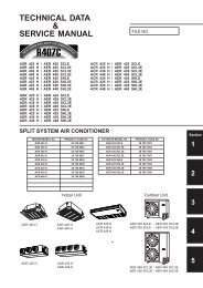
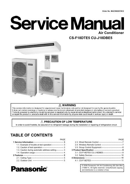
<strong>Air</strong> <strong>Conditioner</strong><br />
CS-F18DTE5 CU-J18DBE5<br />
PAGE PAGE<br />
2.3. Wired Remote Control ------------------------------------7<br />
2.4. Wireless Remote Control --------------------------------7<br />
2.5. Group Control Equipment--------------------------------8<br />
3 Product Specification -------------------------------------------9<br />
3.1. CS-F18DTE5 CU-J18DBE5-----------------------------9<br />
3.2. Safety Devices-------------------------------------------- 10<br />
4Dimensions------------------------------------------------------- 11<br />
4.1. CS-F18DTE5---------------------------------------------- 11<br />
© 2006 <strong>Panasonic</strong> HA <strong>Air</strong>-Conditioning (M) Sdn Bhd<br />
(11969-T). All rights reserved. Unauthorized copying<br />
and distribution is a violation of law.
4.2. CU-J18DBE5---------------------------------------------- 12<br />
5 Refrigeration Cycle--------------------------------------------- 13<br />
5.1. CS-F18DTE5 CU-J18DBE5 --------------------------- 13<br />
6 Block Diagram --------------------------------------------------- 14<br />
6.1. CS-F18DTE5---------------------------------------------- 14<br />
6.2. CU-J18DBE5 --------------------------------------------- 14<br />
7 Wiring Diagram -------------------------------------------------- 15<br />
7.1. CS-F18DTE5 --------------------------------------------- 15<br />
7.2. CU-J18DBE5---------------------------------------------- 16<br />
8 Operation Instructions ---------------------------------------- 17<br />
8.1. Wired Remote Control ---------------------------------- 17<br />
8.2. Remote Control - Display ------------------------------ 18<br />
8.3. Remote Control - Panel -------------------------------- 19<br />
8.4. How to set remote control day and time------------ 20<br />
8.5. How To Select The Timer ------------------------------ 20<br />
8.6. Daily Timer Setting--------------------------------------- 21<br />
8.7. Weekly Timer Setting------------------------------------ 22<br />
8.8. Wireless Remote Control------------------------------- 24<br />
9 Operation Details------------------------------------------------ 25<br />
9.1. Cooling Operation---------------------------------------- 25<br />
9.2. Soft Dry Operation --------------------------------------- 25<br />
9.3. Auto Operation-------------------------------------------- 25<br />
9.4. Fan Operation--------------------------------------------- 25<br />
9.5. Normal Control-------------------------------------------- 26<br />
9.6. Operation Control ---------------------------------------- 27<br />
9.7. Protection Control---------------------------------------- 28<br />
9.8. Test Run ---------------------------------------------------- 29<br />
10 Installation Instruction ---------------------------------------- 30<br />
10.1. Pipe length------------------------------------------------- 30<br />
10.2. Refrigerant additional charge ------------------------- 30<br />
10.3. Position of the centre gravity -------------------------- 31<br />
10.4. Indoor unit installation----------------------------------- 32<br />
10.5. Outdoor unit installation ------------------------------- 42<br />
10.6. Wired remote control installation --------------------- 54<br />
10.7. Wireless remote control installation manual------- 62<br />
11 Installation and Servicing <strong>Air</strong> <strong>Conditioner</strong> Using<br />
R410A --------------------------------------------------------------- 69<br />
11.1. Outline ------------------------------------------------------ 69<br />
11.2. Tools for installing/servicing refrigerant piping ---- 70<br />
11.3. Refrigerant piping work --------------------------------- 74<br />
11.4. Installation, transferring, servicing ------------------- 76<br />
12 Troubleshooting Guide---------------------------------------- 80<br />
12.1. For standard installation -------------------------------- 80<br />
12.2. During group control operation ----------------------- 82<br />
12.3. Test operation and self-diagnosis -------------------- 83<br />
12.4. Emergency operation ----------------------------------- 87<br />
12.5. Self-diagnosis error code table ----------------------- 89<br />
13 Technical Data---------------------------------------------------- 91<br />
13.1. Cooling capacity performance data------------------ 91<br />
13.2. Capacity and power consumption-------------------- 92<br />
13.3. Reaching distance --------------------------------------- 95<br />
13.4. Sound data------------------------------------------------- 96<br />
13.5. Sound measuring point --------------------------------- 97<br />
13.6. Fan performance ----------------------------------------- 98<br />
13.7. Discharge and suction pressure---------------------- 99<br />
13.8. Operating characteristics------------------------------- 99<br />
14 Exploded View (Indoor Unit) ------------------------------ 100<br />
14.1. CS-F18DTE5-------------------------------------------- 100<br />
14.2. CS-F18DTE5-------------------------------------------- 101<br />
14.3. CS-F18DTE5-------------------------------------------- 102<br />
15 Replacement Part List (Indoor Unit) -------------------- 103<br />
2<br />
15.1. CS-F18DTE5 --------------------------------------------103<br />
16 Exploded View (Outdoor Unit) ----------------------------105<br />
16.1. CU-J18DBE5 --------------------------------------------105<br />
16.2. CU-J18DBE5 --------------------------------------------106<br />
17 Replacement Part List (Outdoor Unit) ------------------107<br />
17.1. CU-J18DBE5 --------------------------------------------107<br />
18 Print Pattern -----------------------------------------------------108<br />
18.1. Indoor Unit Printed (Main) ----------------------------108<br />
18.2. Indoor Unit Printed (Indicator) -----------------------109<br />
18.3. Outdoor Unit (Main) ------------------------------------109
1 Service Information<br />
The new Cassette / New Outdoor models are possible to have address setting for twin control by automatic when main<br />
power supply is switched on.<br />
(Manual address setting is also possible by using Dip switch on Indoor unit P.C. board.) However, this address setting is only<br />
possible when made proper wiring connection and also Indoor unit should be original virgin unit.<br />
1.1. Example of trouble at test operation<br />
If found out as following phenomenon at test operation on site, it may have possibility of wrong address setting.<br />
Therefore, please ensure of the address setting.<br />
1. LCD display of wired remote control had not illuminate although the main power supply switch is ‘on’.<br />
2. LCD display had indicated as normal illumination when power supply switch is ‘on’, however outdoor unit cannot be operated.<br />
(But, it is necessary to take 3 to 5 minutes for outdoor unit to start from the timing of remote control ON/OFF switch is ‘on’.)<br />
3. P.C. board had memorized wrong setting information.<br />
a. If main power supply is switched ‘on’ with the wrong connection.<br />
b. When changing the connection or combination of units due to re-installation etc.<br />
• When changing the system from group control to normal one to one system.<br />
• When making the replacement of units as master and slave etc.<br />
1.2. Caution of test operation<br />
Notice of Address setting for NEW Cassette / NEW Outdoor Unit.<br />
Do not touch the remote control switch and do not change any wirings for one minute when the main power supply switch is ‘on’.<br />
(Because the unit is having automatic address setting during the first one minute.)<br />
1.3. Caution during automatic address setting<br />
When main power supply switch is ‘on’, the P.C. board will automatically memorize the connecting system.<br />
Consequently, when initial power supply is ‘on’, there will not be interchangeability of units even of the same type and same capacity<br />
unit. Therefore unable to connect the unit to another system.<br />
3
1.4. Operation range<br />
1.4.1. Power Supply<br />
The applicable voltage range for each unit is given in the following table. The working voltage among the three phases must be balanced<br />
within a 3% deviation from each voltage at the compressor terminals. The starting voltage must be higher than 85% of the<br />
rated voltage.<br />
MODEL Unit Main Power Applicable Voltage<br />
CU- Phase, Volts Hz Max. Min.<br />
1 ~ 220 50 242 198<br />
J18DBE5 1 ~ 230 50 253 207<br />
1 ~ 240 50 264 216<br />
1.4.2. Indoor and Outdoor Temperature<br />
• Model 50Hz CU-J18DBE5<br />
Operating Hz Indoor Temp. (D.B./W.B.) (°C) Outdoor Temp. (D.B./W.B.) (°C)<br />
Max. Min. Max. Min.<br />
Cooling 50 32/23 21/15 43/- -5/-<br />
4
2 Features<br />
2.1. Ceiling Type<br />
2.1.1. Easier Maintenance and Cleaning<br />
• Anti-Mould Long Life <strong>Air</strong> Filter.<br />
• 3-Direction Pipe Lead-Out.<br />
2.1.2. Wide <strong>Air</strong> Discharge, Comfortable Control<br />
• Wide-Angle <strong>Air</strong>flow — 100 Degrees Horizontal.<br />
• Auto Swing Louver.<br />
2.2. Outdoor Unit<br />
2.2.1. Flexible Installation in Smaller Spaces<br />
• Long Pipe design with maximum piping length of 30m.<br />
• Flexible 4-way piping.<br />
5
• Centralized Drain Method gathered multiple outdoor unit’s drain pipes into a single drain pipe to makes installation easier and<br />
also improve appearance.<br />
• Side-by-Side Continuous Installation is possible even outdoor units with different capacities.<br />
2.2.2. Quiet, Efficient Design<br />
• A host of silencing technologies achieves super-quiet operation.<br />
• The Noise-Suppressing Winglet Fan is a result of new research into vane design theory. The unique curved shaped suppressed<br />
the generation of vortexes, thus reduces air flows noise.<br />
• Operating efficiency is improved and energy consumption reduced.<br />
2.2.3. Low Ambient Cooling Operation<br />
• The unit can set for cooling even when the outdoor temperature drops to -10°C. This is ideal for location such as non-residential<br />
computer room (where the temperature is not less than 21°C and humidity is not more than 45%) that require cooling even in<br />
winter.<br />
6
2.3. Wired Remote Control<br />
1. The new design includes an easily-visible red pilot lamp. The power can be turned on and off at a single touch, without opening<br />
the cover.<br />
2. Has a build-in thermistor, allowing indoor temperature detection in accordance with indoor conditions by switching with main<br />
unit thermistor.<br />
3. Twin non-polar wires make installation work easy. (10 m cable supplied as accessory.)<br />
2.4. Wireless Remote Control<br />
1. New design with compact size. (Operation range within approximately 8 m.)<br />
2. Built-in timer with OFF/ON timer setting (within 24 hours)<br />
Wired Wireless<br />
CZ-RD513C CZ-RL513T<br />
NOTE: Both of the above remote control is packed separately from the indoor unit.<br />
7
2.5. Group Control Equipment<br />
Wired<br />
remote<br />
control<br />
Common<br />
control<br />
Group control by one remote control<br />
• All air conditioner units are controlled<br />
as a whole by remote control.<br />
• All indoor units operate in the same<br />
mode.<br />
Twin remote control separate control<br />
• Each indoor unit can be operated by<br />
either one of the two remote control.<br />
• Apart from timer setting time, displays<br />
for two remote control are<br />
identical.<br />
• Last button pressed has priority<br />
(main or slave is set at remote control<br />
unit).<br />
Common control / group<br />
• Operation is possible using either<br />
wired or wireless remote control<br />
unit.<br />
• Last button pressed has priority.<br />
8<br />
[Remote side]<br />
• Optional wired remote control<br />
CZ-RD513C<br />
[Local side]<br />
Not needed<br />
[Remote side]<br />
• Optional wired remote control<br />
[Local side]<br />
• Optional wired remote control<br />
CZ-RD513C<br />
• Optional wired remote control<br />
and wireless remote<br />
control<br />
Wired CZ-RD513C<br />
Wireless CZ-RL513T
3 Product Specification<br />
3.1. CS-F18DTE5 CU-J18DBE5<br />
Indoor Unit Outdoor Unit<br />
ITEM / MODEL Main Body CS-F18DTE5 CU-J18DBE5<br />
Remote CZ-RD513C (Wired)<br />
Control CZ-RL513T (Wireless)<br />
Cooling Capacity kW 5.0<br />
BTU/h 17,100<br />
Refrigerant Charge-less m 20<br />
Standard <strong>Air</strong> Volume for High Speed m3 /min 14 57<br />
cfm 494 2013<br />
Outside Dimension (H × W × D) mm 210 × 1245 × 700 795 × 900 × 320<br />
inch 8-9/32 × 49-1/64 × 27-9/16 31-5/16 × 35-7/16 × 12-19/32<br />
Net Weight kg (lbs) 33 (73) 57 (126)<br />
Piping Refrigerant Gas mm (inch) O.D Ø 12.70 (1/2) Flared Type<br />
Connection Liquid mm (inch) O.D Ø 6.35 (1/4) Flared Type<br />
Drain O.D Ø 20 I.D Ø 20<br />
Compressor Type, Number of Set — Hermetic, 1<br />
Starting Method — Permanent Split Capacitor<br />
Motor Type — 2-pole 1 phase brushless motor<br />
Rated Output kW — 1.5<br />
Fan Type, Number of Set Sirocco fan-4 Mix flow fan-1<br />
Motor Type 4-pole single phase induction motor 6-pole single phase induction motor<br />
Rated Output kW 0.022 0.07<br />
<strong>Air</strong>-heat Exchanger (Row × Stage × FPI) Louver-fin type (2 × 12 × 18) Corrugate-fin type (1 × 36 × 21)<br />
Refrigerant Control — Expansion Valve<br />
Refrigerant Oil (Charged) cm3 — FV50S<br />
Refrigerant (Charged) R410A kg (oz) — 1.10 (38.8)<br />
Running Control Switch Wireless or Wired Remote Control —<br />
Adjustment Room Temperature Thermostat —<br />
Noise Level dB (A) Cooling: 41/37 49/-<br />
Power level<br />
dB<br />
Cooling: 58/54 65/-<br />
Moisture Removal L/h (Pt/h) 2.8 (5.9)<br />
EER W/W 2.81/2.76/2.72<br />
1. Cooling capacities are based on indoor temperature of 27°C D.B. (80.6°F D.B.), 19.0°C W.B. (66.2°F W.B.) and outdoor air<br />
temperature of 35°C D.B. (95°F D.B.), 24°C W.B. (75.2°F W.B.)<br />
2. Heating capacities are based on indoor temperature of 20°C D.B. (68°F D.B.) and outdoor air temperature of 7°C D.B. (44.6°F<br />
D.B.), 6°C W.B. (42.8°F W.B.)<br />
ELECTRICAL DATA (50 Hz)<br />
ITEM / MODEL Condition by ISO5151<br />
Volts V 220 230 240<br />
Phase Single Single Single<br />
Power Consumption kW Cooling 1.78 1.81 1.84<br />
Running Current A Cooling 8.15 8.10 8.05<br />
Starting Current A 26 27 28<br />
Power Factor % Cooling 99 97 95<br />
*Power Factor means total figure of compressor, indoor fan motor and outdoor fan motor.<br />
<strong>Panasonic</strong> Power source AC, 1~220V, 230V, 240V 50Hz<br />
9
3.2. Safety Devices<br />
INDOOR UNIT<br />
Indoor Unit Cooling Only Model CS-F18DTE5<br />
For fan motor protection<br />
Internal OFF °C 135<br />
Protector ON °C 87<br />
For control protection<br />
Fuse CUT A 3.15<br />
OUTDOOR UNIT<br />
Outdoor Unit<br />
For refrigerant cycle<br />
Cooling Only Model 50Hz CU-J18DBE5<br />
High pressure OFF MPa 4.15<br />
Switch (63H1)<br />
For compressor<br />
Over current protection<br />
ON MPa 3.05<br />
Cooling Only Model OFF A —<br />
Discharge temp protection<br />
RESET — Automatic<br />
Discharge Compressor<br />
temperature<br />
thermistor (Th1)<br />
Liquid compress protection<br />
OFF °C 114<br />
Crankcase heater<br />
Compressor protection<br />
Input Power W 37 × 2<br />
Internal protector OFF °C<br />
50Hz<br />
160<br />
ON °C<br />
50Hz<br />
90<br />
For fan motor protection<br />
Trip<br />
Time<br />
50Hz 3-10sec/35A<br />
Internal OFF °C 135<br />
Protector (49F)<br />
Heating control (Heat pump only)<br />
ON °C 85<br />
Pressure switch OFF MPa —<br />
(Fan speed) (63H2) ON MPa —<br />
Cooling control<br />
Heat exchanger Th 40°C ——— High speed<br />
temperature Control Method Th 40°C ——— 5 speed step control<br />
thermistor (Th2)<br />
For control protection<br />
Fuse CUT A 6.3<br />
1MPa=10.2kgf/cm 2<br />
10
4 Dimensions<br />
4.1. CS-F18DTE5<br />
11
4.2. CU-J18DBE5<br />
12
5 Refrigeration Cycle<br />
5.1. CS-F18DTE5 CU-J18DBE5<br />
13
6 Block Diagram<br />
6.1. CS-F18DTE5<br />
6.2. CU-J18DBE5<br />
14
7 Wiring Diagram<br />
7.1. CS-F18DTE5<br />
15
7.2. CU-J18DBE5<br />
16
8 Operation Instructions<br />
8.1. Wired Remote Control<br />
Name and function of each part<br />
REMOTE<br />
The OFF/ON button cannot be used.<br />
LOCAL<br />
All wired remote control buttons can be used.<br />
Time/time setting display<br />
Check display<br />
Fan speed display<br />
Operation mode selection display<br />
FILTER RESET display<br />
(Appears after the cumulative running time reaches approximately<br />
2,500 hours of operation.)<br />
Temperature setting display (16°C - 31°C)<br />
NOTES<br />
• Ensure that the correct button is pressed as simultaneous pressing of the multiple buttons will not make the setting correct.<br />
• The illustration above is for explanatory purposes only. The appearance will be different during actual operation.<br />
• Do not operate the remote control with wet hands. Otherwise, electric shock or malfunction may occur.<br />
• Do not press the remote control buttons with sharp object as this may damage the remote control.<br />
• Buttons marked with * are not needed for normal operation. If one of these buttons is pressed by mistake, press the same button<br />
once more to cancel the operation.<br />
• When the power resumed after power failure, the unit will restart automatically with all the previous settings preserved by the<br />
memory function. (Auto restart function)<br />
17<br />
<strong>Air</strong>flow direction setting display<br />
OFF/ON button<br />
Used to start and stop the operation.<br />
FAN SPEED button<br />
Used to select the fan speed of high (HI), medium (MED), low<br />
(LO) or auto (AUTO).<br />
MODE button<br />
Used to select the operation of AUTO, FAN, COOL, or DRY.<br />
TEMP (UP/DOWN) buttons<br />
Used to select the desired temperature.<br />
AIR SWING (AUTO/MANUAL) buttons<br />
Used to determined the air swing condition, either auto or<br />
manual.<br />
FILTER RESET button<br />
Press to reset the “FILTER RESET” display after washing the filter.<br />
TEST RUN button*<br />
VENTILATION button*<br />
ECONOMY operation button<br />
Provides Energy saving function<br />
ODOUR WASH button<br />
Provides deodorizing function.<br />
CHECK button<br />
Press this button if the check display is flashing.<br />
TIMER/CLOCK SET buttons<br />
Used to set the timer operation and the current time.<br />
Operation indicator<br />
Lights up when the unit in operation.
8.2. Remote Control - Display<br />
18
8.3. Remote Control - Panel<br />
19
8.4. How to set remote control day and time<br />
• The day and time needs to be set when you turn on the power for the first time or after a long time has elapsed since the power<br />
was last turned on.<br />
• The day and time becomes the standard time for all the Timer operations.<br />
• Set the day and time accurately.<br />
• Example : Current Day is Wednesday and Current Time is 8:00.<br />
Note:<br />
• Press “UP button” to increase or “DOWN button” to decrease (interval 1 minute) or hold the button to change the time faster.<br />
• If the “UP or DOWN button” is not pressed for 30 seconds during the day or time setting or if the “SELECT button” is pressed, the<br />
setting at that moment is confirmed and setting will end.<br />
8.5. How To Select The Timer<br />
• 2 types of Timer mode can be selected on the remote control.<br />
- Daily Timer<br />
- Weekly Timer<br />
• These timers cannot be operated simultaneously.<br />
• Select one of these Timers for your convenience.<br />
How to Change the Display<br />
• Press once to change the display from CLOCK to Timer or vice-versa.<br />
• Press more than 3 seconds to change the display from Daily Timer to Weekly Timer or vice-versa.<br />
20
CLOCK Display (To set current Day and Time)<br />
Note:<br />
• The above display is shown if no valid timer setting is made.<br />
• If valid timer setting is made.<br />
- and setting will be displayed.<br />
- If you want to check the current time and day, press “MODE button” once.<br />
(However, after a few seconds, the display will change back to and the setting)<br />
8.6. Daily Timer Setting<br />
•Display<br />
• How to Set Daily Timer<br />
- You can set only “ON” or only “OFF” or “ON” and “OFF” in a day.<br />
1. Change Display<br />
Press “MODE button” to change the display to daily timer.<br />
2. ON-Timer, OFF-Timer and select Time<br />
Press “SELECT button”; ON-Timer setting will be displayed.<br />
Press “UP or DOWN button” to select the desired time, (Example: ON 9:00), then press “SET button” to confirm the<br />
selected desired time.<br />
Or press “CANCEL button” if you do not want any setting for ON-Timer.<br />
Then OFF-Timer setting will be displayed.<br />
Press “UP or DOWN button” to select the desired time, (Example: OFF 18:30), then press “SET button” to confirm<br />
the selected desired time.<br />
Or press “CANCEL button” if you do not want any setting for ON-Timer.<br />
Note:<br />
• The setting timer will be activated everyday.<br />
• Timer nearer to the current time will be activated first.<br />
21
Final Display of Daily Timer:<br />
8.7. Weekly Timer Setting<br />
• Display<br />
• How to Set Weekly Timer<br />
- You can set the Timer for 1 week (Monday to Sunday) with 6 programs per day.<br />
- ON-Timer can be set together with your desired temperature. However, this temperature will be used continuously.<br />
- Cannot set 2 programs with same time setting in a day.<br />
- You also may select Collective - many days with same time setting or Individual<br />
- single/one day setting.<br />
1. Change Display<br />
Press “MODE button” to change the display to weekly timer.<br />
2. Select Day (please refer to next page for example of setting)<br />
You may select Collective or Individual day setting.<br />
• Collective day setting.<br />
Press “SELECT button”: display will show day selection setting.<br />
Press “UP or DOWN button” to select the day. Then press “SET button” to delete triangle<br />
mark (deselect) or add triangle mark (select).<br />
(Triangle mark on top of each day indicates the day to be selected).<br />
Repeat these steps if you want to deselect or select many days.<br />
To confirm the selected days, press the “SELECT button”.<br />
• Individual day setting.<br />
Press “UP or DOWN button” to select the day.<br />
Then press “SELECT button”.<br />
3. Select Time (please refer to next page for example of setting)<br />
For 1st program setting.<br />
Press “UP or DOWN button” to select ON or OFF.<br />
Then press “SET button” to confirm.<br />
Press “UP or DOWN button” again to select the desired time.<br />
(If you want to set them together with your desired temperature, press “TEMP UP/DOWN button”<br />
to select the temperature).<br />
Then press “SET button” to confirm.<br />
Or press “CANCEL button” if you do not want to set any time.<br />
For 2nd ~ 6th program you may refer to the above step.<br />
22
For example , if you want to set:<br />
A - Monday to Friday: Same time, 1st program ON 9:00 & 2nd program OFF 16:00.<br />
B - Only Wednesday: Additional 3rd program OFF 12:30 & 4th program ON 13:30.<br />
C - Only Saturday: 1st program ON 10:00 with 20°C & 2nd program OFF 14:00.<br />
D - Sunday: Holiday. No need to set any Timer.<br />
• To set A (Monday to Friday - Collective day setting)<br />
Press “SELECT button”<br />
To select Monday to Friday, deselect Saturday and Sunday by pressing “UP or DOWN button” to Saturday, press<br />
“SET button” (triangle mark on top of Saturday will disappear)<br />
Follow the same step to deselect Sunday.<br />
Ensure triangle mark appears on top of Monday ~ Friday.<br />
- To confirm the selected days, press “SELECT button”.<br />
To set the time, please refer to step 3. Select time at page 22.<br />
- 1st program - select ON and desired time to 9:00.<br />
2nd program - select OFF and desired time to 16:00.<br />
3rd ~ 6th program - press “CANCEL button”.<br />
• To set B (Wednesday - Individual day setting)<br />
- Press “UP or DOWN button” to select WED (Wednesday).<br />
Then press “SELECT button”.<br />
To set the time, please refer to step 3. Select time at page 22.<br />
- 1st program - press “SET button” twice (confirm ON and 9:00)<br />
2nd program - also press “SET button” twice. (Confirm OFF and 16:00)<br />
3rd program - select OFF and desired time to 12:30<br />
4th program - select ON and desired time to 13:30<br />
5th ~6th program - press “CANCEL button”<br />
• To set C (Saturday - Individual day setting)<br />
- Follow the same step as above.<br />
To set the time, please refer to step 3. Select time at page 22.<br />
- 1st program - select ON, desired time to 10:00 and desired temperature to 20°C.<br />
2nd program - select OFF and desired time to 14:00.<br />
3rd ~ 6th program - press “CANCEL button”.<br />
- Final Display for Weekly timer may show as:<br />
(Display is showing, 9:00 ON - Timer on Wednesday will be activated next because it is nearest the current<br />
day/time.)<br />
Note:<br />
• Timer that has setting nearest to current time and day will be activated first.<br />
• To check the setting timer, press “SELECT button”, then “UP or DOWN button” to select day. The display will show each program<br />
for the selected day.<br />
• To reset the setting for all, press “SELECT button”, then ensure all day setting with triangle mark. Then press “CANCEL button”<br />
for all the programs.<br />
23
8.8. Wireless Remote Control<br />
Name and function of each part<br />
Transmitter<br />
Transmits the remote control signal.<br />
<strong>Air</strong>flow direction setting display<br />
Fan speed display<br />
Temperature setting display (16°C - 31°C)<br />
Time/time setting display<br />
Shows the timer operation setting time or the current time.<br />
NOTES<br />
• Ensure that the correct button is pressed as simultaneous pressing of the multiple buttons will not make the setting correct.<br />
• The illustration above is for explanatory purpose only. The appearance will be different during actual operation.<br />
• If using the wireless remote control in conjunction with the wired remote control, the settings made from the wireless remote control<br />
will appear on the wired remote control display (except when making timer settings).<br />
• Buttons marked with * are not needed for normal operation. If one of these buttons is pressed by mistake, press the same button<br />
once more to cancel the operation.<br />
• When the power resumed after power failure, the unit will restart automatically with all previous settings preserved by the<br />
memory function. (Auto restart function)<br />
24<br />
Address number display<br />
Operation selection display<br />
OFF/ON button<br />
Used to start and stop the operation.<br />
ODOUR WASH button<br />
FILTER RESET button<br />
Press to cancel the “FILTER” indicator light on the control panel.<br />
FAN SPEED button<br />
Used to select the fan speed of high (HI), medium (MED), low<br />
(LO) or auto (AUTO).<br />
SET button*<br />
Local setting function.<br />
ADDRESS SET button*<br />
Used to change the address setting when using more than one<br />
indoor unit.<br />
RESET button<br />
Pressing this button will clear all the settings from memory.<br />
You will then need to make the settings again.<br />
TIMER/CLOCK SET buttons<br />
Used to set the timer operation and the current time.<br />
AIR SWING (AUTO/MANUAL) buttons<br />
Used to determine the air swing condition, either auto or manual.<br />
MODE button<br />
Used to select the operation of AUTO, FAN, COOL or DRY.<br />
TEMP (UP/DOWN) buttons<br />
Used to select the desired temperature.<br />
ECONOMY operation button
9 Operation Details<br />
9.1. Cooling Operation<br />
• Cooling operation can be set using remote control.<br />
• This operation is applied to cool down the room temperature reaches the setting temperature set on the remote control.<br />
• Cooling Operation Time Diagram.<br />
9.2. Soft Dry Operation<br />
• Soft Dry Operation can be set using remote control.<br />
• Soft Dry operation is applied to dehumidify the room.<br />
• When operation begins, the fan speed is fixed at Low speed while cooling operation is running until reaches the remote control<br />
setting temperature.<br />
9.3. Auto Operation<br />
• Automatic Mode can be set using remote control.<br />
• This operation starts to judge the intake air temperature, setting temperature, and outdoor piping temperature. Then the unit<br />
starts to operate at determined operation mode.<br />
9.4. Fan Operation<br />
• Fan operation can be set using remote control.<br />
• The indoor fan is operated at High, Medium or Low speed according to remote control setting.<br />
25
9.5. Normal Control<br />
9.5.1. Cooling Indoor Fan Control<br />
• Manual Fan Speed<br />
Operation starts at High, Medium or Low speed set by remote control.<br />
• Auto Fan Speed<br />
When operation start, or shifting to thermostat ON condition from thermostat OFF condition, indoor fan operates as below.<br />
Thermostat & Compres-<br />
Thermostat &<br />
Thermostat &<br />
Thermostat &<br />
sor ON/OFF<br />
Compressor ON<br />
Compressor OFF<br />
Compressor ON<br />
Time 40 sec. 50 sec. - 20 sec. 120 sec. 20 sec. 40 sec. 50 sec. -<br />
Cooling Auto Off Lo Hi Lo Off Lo Off Lo Me<br />
Soft Dry Auto Off Lo Lo Lo Off Lo Off Lo Lo<br />
9.5.2. Louver control<br />
• When power is on, at the same time, louver initialize 2 times.<br />
• During operation, stopping, thermostat is off condition, louver angle change as below table by manual setting or auto setting of<br />
remote controller.<br />
Remote controller setting Manual Auto<br />
Operation mode Display<br />
Set 1<br />
Set 2<br />
Set 3<br />
Set 4<br />
Piping temp (heating)<br />
A B C<br />
Fan 20° 35° 50° 70° 20° - 70°<br />
Cooling Normal 20° 35° 50° 70° 20° - 70°<br />
(fan) Dew control 35°<br />
Thermostat off 20° 35° 50° 70° 20° - 70°<br />
Normal 35°<br />
Soft Dry Dew control 35°<br />
Thermostat off 20° 35° 50° 70° 20° - 70°<br />
Operation mode judge 20° 35° 50° 70° 20°<br />
Stop mode 70°<br />
9.5.3. Cooling Outdoor Fan Control<br />
• During cooling operation, outdoor fan speed changes according to outdoor pipe temperature.<br />
• The fan speed is controlled by the timing of turning the outdoor fan ON and OFF within an interval.<br />
• When outdoor pipe temperature increase, interval timing increased.<br />
• Outdoor fan ON time is a variable with the range of 200ms to 2000ms.<br />
• After 2 minutes, the outdoor pipe temperature is detected and the outdoor unit fan speed is changed automatically.<br />
26
9.6. Operation Control<br />
9.6.1. Odour Cut Control<br />
• Odour cut operation removes the odour generated at indoor heat exchanger by using drain water come out from indoor heat<br />
exchanger.<br />
• Press “Odour” button at remote control to enable odour cut operation.<br />
• Odour cut operation starts when compressor or thermostat is on.<br />
Thermostat & Compres-<br />
Thermostat &<br />
Thermostat &<br />
Thermostat &<br />
sor ON/OFF<br />
Compressor ON<br />
Compressor OFF<br />
Compressor ON<br />
Time 40 sec. 50 sec. - 20 sec. 120 sec. 20 sec. 40 sec. 50 sec. -<br />
Cooling Off Lo Normal Lo Off Lo Off Lo Normal<br />
Operation<br />
Operation<br />
Soft Dry Off Lo Lo Lo Off Lo Off Lo Lo<br />
9.6.2. Energy Saving<br />
• During Operation, press "Economy" button at remote control to enable Energy Saving Operation.<br />
• The air conditioner judges the stable condition, where the different between indoor suction temperature and setting temperature<br />
is 1°C for 30 minutes and moderately shifts the set temperature in 0.5°C steps (Maximum 2°C) to control energy saving operation.<br />
• If temperature different is out of range, energy save operation will not start.<br />
• Energy Save Operation is canceled by pressing the "Economy" button again.<br />
Energy save control time chart<br />
9.6.3. Dew Form Prevention Control<br />
• During Cooling or Soft Dry operation, if outdoor temperature is less than 30°C, and indoor fan speed is low or auto setting, indoor<br />
heat exchanger temperature become lower, dew form prevention control start to prevention dew form at indoor discharge grille.<br />
• When indoor pipe temperature decrease, the cooling capacity will be reduced and the louver angle will be fixed at certain angle.<br />
9.6.4. Freeze Prevention Control<br />
• After compressor starts operation for 4 minutes, the outdoor unit will stop its operation if indoor pipe temperature falls below 0°C<br />
for 6 minutes.<br />
• After 3 minutes stops, compressor restarts operation if indoor pipe temperature is 6°C or more.<br />
• This phenomenon is to protect the indoor heat exchanger from freezing and to prevent higher volume of refrigerant in liquid from<br />
returning to the compressor.<br />
9.6.5. Time Delay Safe Control<br />
• The compressor will not start for three minutes after stop of operation.<br />
9.6.6. Outdoor Fan Remaining Heat Removal Control<br />
• When compressor stop, outdoor fan operates at High speed for 1 minute to remove the remaining heat.<br />
27
9.6.7. Thermostat Control<br />
• Depending on differences between room temperature and setting temperature, compressor operation is decided and starts operation.<br />
• If temperature difference matches values shown below, thermostat switches off.<br />
9.7. Protection Control<br />
9.7.1. Outdoor Low-pressure Protection Control<br />
• The purpose of low-pressure protection control is gas leakage detection control.<br />
• The low-pressure protection control starts when low-pressure switch is activated less than 15 minutes after compressor startup.<br />
• During this protection control, compressor is shut down, indoor unit is set to thermo-off status.<br />
• After 6 occasions, suction pressure error is displayed; all operation stopped except outdoor fan remaining heat removal control.<br />
9.7.2. Outdoor High-pressure Protection Control<br />
• The high-pressure protection control starts when high-pressure switch is activated less than 15 minutes after compressor startup.<br />
• During this protection control, compressor is shut down. And indoor unit is set to thermo-off status.<br />
• After 6 occasions, high-pressure protection error is displayed; all operation stopped except outdoor fan remaining heat removal<br />
control.<br />
9.7.3. Discharge Temperature Protection Control<br />
• The discharge temperature protection control starts when abnormal compressor temperature 115°C is detected when outdoor<br />
unit is operating in cooling operation.<br />
• During this protection control, compressor is shut down. And indoor unit is set to thermo-off status.<br />
• After 6 occasions, high-pressure protection error is displayed; all operation stopped except outdoor fan remaining heat removal<br />
control.<br />
Cooling Mode -1.5°C<br />
Soft Dry Mode -2.5°C<br />
9.7.4. Over Current Protection Control<br />
• The purpose of over current protection control is to protect the air conditioner from over current.<br />
• The over current protection control starts when input current from CT is maintained at 20A or more for 2 seconds when the outdoor<br />
unit is starting up or during cooling operation.<br />
• During this protection control, compressor is shut down. And indoor unit is set to thermo-off status.<br />
• After 4 occasions, over current protection error is displayed; all operation stopped except outdoor fan remaining heat removal<br />
control.<br />
9.7.5. CT Disconnection Detection Control<br />
• CT disconnection detection control detects if the CT sensor works normally.<br />
• The CT disconnection detection activates when:<br />
- CT input value is maintained at compressor shutdown status (1.5A or less) consecutively for 2 seconds when the compressor<br />
is operating.<br />
- During this condition, compressor is shut down and indoor unit is set to thermo-off status.<br />
- After 4 occasions, CT sensor error is displayed; all operation stopped except outdoor fan remaining heat removal control.<br />
- CT input value is maintained at compressor operation status (5A or more) consecutively for a period of 60 seconds when the<br />
compressor is shut down.<br />
- During this condition, CT sensor error is displayed.<br />
9.7.6. Connection Capacity Protection Control<br />
• The purpose of connection capacity protection control is to ensure the total capacity of connected indoor units is within acceptable<br />
range.<br />
Model Number Min. Capacity (kW) Max. Capacity (kW) Model Number Min. Capacity (kW) Max. Capacity (kW)<br />
CU-J14DBE5 5.3 6.9 CU-B28DBE8 6.3 9.8<br />
CU-J18DBE5 5.3 6.9 CU-B34DBE8 7.3 12.3<br />
CU-J24DBE5 5.3 6.9 CU-B43DBE8 10.2 13.8<br />
CU-J28DBE5 6.3 9.8 CU-B50DBE8 12.7 15.8<br />
CU-J34DBE5 7.3 12.3<br />
• During this protection control, connection capacity error is displayed; all operations stopped.<br />
28
9.7.7. Sensor Disconnection Detection Control<br />
• The sensor disconnection detection control activates when the following condition comply:<br />
Sensor Detection Threshold Duration (Sec.) Detection Condition<br />
Discharge Temperature < -4.5°C or 201.8°C 5 Other than compressor start control<br />
and compressor ON<br />
Outdoor Heat Exchanger < -50.5°C or 103.7°C 5 Regularly<br />
• During sensor disconnection, sensor error is displayed; all operations stops except outdoor fan remaining heat removal control.<br />
9.7.8. High-pressure Switch Disconnection Error Detection Control<br />
• High-pressure switch disconnection is detected when high-pressure switch input continuously open for 1 minutes while the compressor<br />
shutdown.<br />
• During this error, high-pressure switch error is displayed.<br />
9.7.9. Low-pressure Switch Disconnection Error Detection Control<br />
• Low-pressure switch disconnection is detected when low-pressure switch input continuously open for 1 minutes while compressor<br />
shutdown.<br />
• During this error, low-pressure switch error is displayed.<br />
9.8. Test Run<br />
• Test run is necessary after installation is completed.<br />
• To enable forced cooling test run, at outdoor PCB, set the DS1 to position below:<br />
• To enable forced heating test run, at outdoor PCB, set the DS1 to position below:<br />
• Press Test Run button at outdoor pcb for 1 second.<br />
29
10 Installation Instruction<br />
10.1. Pipe length<br />
• CORRECTION OF CAPACITIES<br />
1. Correction of capacities according to the connecting pipe length.<br />
The data of rated capacities (marked on the name plate) are based on 7.5 meters connecting pipe and horizontal installation.<br />
2. For other pipe length of other installation multiply by the following correction factor to determine the revised cooling capacity.<br />
Note :<br />
Piping elevation B = outdoor unit installed at top<br />
Piping elevation C = outdoor unit installed at bottom<br />
10.2. Refrigerant additional charge<br />
Piping Size / Length & Elevation<br />
Model No. Piping size Piping<br />
length<br />
(A)<br />
Liquid /<br />
High<br />
Valve Gas /<br />
Low<br />
1. Piping installation by standard piping<br />
• At the time of shipment from the factory, this unit is charged with enough refrigerant for an equivalent pipe length of 20m.<br />
(Refer the following table)<br />
But when the piping length exceeds 20m, additional charge is required according to the following table.<br />
Example:<br />
CU-J18DBE5<br />
In case of 30m long pipe (one way), the amount of refrigerant to be replenished is: (30 - 20) x 20 = 200g<br />
30<br />
Piping<br />
elevation<br />
(B)<br />
Piping<br />
elevation<br />
(C)<br />
Piping<br />
Chargeless<br />
Add<br />
Refrigerant<br />
Valve Max(m) Max(m) Max(m) Max(m) (g/m)<br />
R<br />
Cassette 4<br />
type 1 CS-F18DTE5 6.35 3-ways 12.70 3-ways 30 20 20 20 20<br />
0<br />
A<br />
Model Name Standard piping specification<br />
Liquid piping Gas piping Gas chargeless Additional gas<br />
(dia.mm) (dia.mm) length (m) volume (g/m)<br />
CU-J18DBE5 6.35 12.7 20 20
10.3. Position of the centre gravity<br />
MODEL NAME OUTSIDE DIMENSIONS NET WEIGHT CENTRE OF GRAVITY<br />
WIDTH (mm) DEPTH (mm) HEIGHT (mm) kg X (mm) Y (mm) Z (mm)<br />
CU-J18DBE5 900 320 795 69 560 150 320<br />
31
10.4. Indoor unit installation<br />
CEILING TYPE AIR CONDITIONERS INSTALLATION INSTRUCTIONS<br />
Precautions in terms of safety<br />
Carry out installation work with reliability after throughout reading of this “Precautions in terms of safety”.<br />
• Precautions shown here are differentiated between Warnings and Cautions. Those that have much chance for leading to<br />
significant result such as fatality or serious injury if wrong installation would have been carried out are listed compiling them<br />
especially into the column of Warnings.<br />
However, even in the case of items which are listed in the column of Cautions, such items also have a chance for leading to<br />
significant result depending on the situations.<br />
In either case, important descriptions regarding the safety are listed, then observe them without fail.<br />
• As to indications with illustration<br />
This mark means “Caution” or “Warning”. This mark means “Earth”.<br />
• After installation work has been completed, do not only make sure that the unit is free from any abnormal condition through the<br />
execution of trial run but also explain how to use and how to perform maintenance of this unit to the customer according to the<br />
instruction manual.<br />
In addition, request the customer to keep this manual for installation work together with instruction manual.<br />
The appliance must be installed by technician, who takes into<br />
account the requirements given by ISO5149 or eventual equivalent<br />
requirements.<br />
As to installation, request the distributor or vendor to perform it.<br />
Imperfection in installation caused by that having been carried out<br />
by the customer himself may lead to water leakage, electric shock,<br />
fire, etc.<br />
Carry out the installation work with reliability according to this<br />
manual for installation work.<br />
Imperfection in installation leads to water leakage, electric shock,<br />
fire, etc.<br />
Carry out the installation work with reliability on the place that can<br />
bear the weight of this unit sufficiently. Insufficient strength leads to<br />
injury due to falling of the unit.<br />
Carry out predetermined installation work in preparation for strong<br />
wind such as typhoon, earthquake. Imperfection in installation<br />
work may lead to accidents arisen from overturn, etc.<br />
Warnings<br />
32<br />
If installing inside a small room, measures should be taken to prevent<br />
refrigerant levels from building up to critical concentrations in<br />
the event of a refrigerant leak occurring. Please discuss with the<br />
place of purchase for advice on what measures may be necessary<br />
to prevent critical concentrations being exceeded. If the refrigerant<br />
leaks and reaches critical concentration levels, there is the danger<br />
that death from suffocation may result.<br />
Securely attach the protective covers for the outdoor unit connection<br />
cables and power cord so that they do not lift up after installation.<br />
If the covers are not properly attached and installed, the<br />
terminal connections may overheat, and fire or electric shock may<br />
result.<br />
Switch off all supplies before accessing any electrical part.<br />
If refrigerant gas escapes during installation, ventilate the affected<br />
area. If the refrigerant gas comes into contact with sparks or naked<br />
flames, it will cause toxic gases to be generated.<br />
Once installation work is completed, check that there are no refrigerant<br />
gas in the room that can come into contact with sparks or<br />
flames from a fan heater, stove or kitchen range, which will cause<br />
toxic gases to be generated.
The unit must be installed in accordance with applicable national<br />
and local regulations.Any electrical work should only be carried<br />
out by qualified technician and use exclusive circuits without fail.<br />
Presence of insufficient capacity in power circuit or imperfection in<br />
execution leads to electric shock, fire, etc.<br />
Wiring shall be connected using specified cables and fix them<br />
securely so that external force of the cables may not transfer to the<br />
terminal connection section.<br />
Imperfect connection and fixing leads to fire, etc.<br />
When performing piping work do not mix air except for specified<br />
refrigerant (R22) in refrigeration cycle. it causes capacity down,<br />
and risk of explosion and injury due to high tension inside the<br />
refrigerant cycle.<br />
Do not install the unit at the place where the possibility of inflammable<br />
gas leakage exists. If gas leakage should arise and the gas<br />
builds up around the unit, such situation may lead to ignition.<br />
Drain piping should be made to ensure secure drainage according<br />
to the manual for installation work and carry out the thermal insulation<br />
to prevent the occurrence of condensation.<br />
Imperfection in piping work lead to water leakage and may cause<br />
the house and property, etc. to become wet.<br />
Cautions<br />
10.4.1. Accessories packed in the indoor unit container<br />
10.4.2. Selecting the location for indoor unit<br />
Provide a check port on the piping side ceiling for repair and maintenance.<br />
• Install the indoor unit once the following conditions are satisfied and after receiving the customer approval.<br />
1. The indoor unit must keep a maintenance space.<br />
2. The indoor unit must be free from any obstacles in path of the air inlet and outlet, and must allow spreading of air throughout<br />
the room.<br />
3. The installation position must be able to support a load four times the indoor unit weight. Warnings<br />
4. The installation location (surface that the unit is suspended from) must be horizontal (and guaranteed to stay horizontal).<br />
5. The indoor unit must be away from heat and steam sources, but avoid installing it near an entrance.<br />
6. The indoor unit must allow easy draining.<br />
7. The indoor unit must allow easy connection to the outdoor unit.<br />
8. The indoor unit must be at least 3m away from any noise-generating equipment. The electrical wiring must be shielded<br />
with a steel conduit.<br />
9. If the power supply is subject to noise generation, add a suppressor.<br />
10. Do not install the indoor unit at a laundry. Electric shocks may result.<br />
33<br />
Earth<br />
This equipment must be properly earthed.<br />
Earth line must not be connected to earth of gas<br />
pipe, water pipe, lightning rod and telephone.<br />
Otherwise, it may cause electrical shock in case<br />
the equipment breakdown or has leakage current.<br />
Installation of Earth Leakage Current Breaker<br />
This equipment must be installed with earth leakage<br />
current breaker.<br />
Otherwise, it may cause electrical shock and fire in case<br />
the equipment breakdown or has leakage current.<br />
Position the indoor unit and outdoor unit, power cords and indoor/<br />
outdoor unit connection cables in a way so that they are at least 1<br />
meter away from televisions and radios.<br />
This is to avoid problem such as interference with picture and/or<br />
sound. (However, note that depending on the electromagnetic<br />
wave conditions, interference may still occur even if the separation<br />
distance is more than 1 meter.)<br />
Name Q’ty Appearance Purpose Name Q’ty Appearance Purpose<br />
Band 4 For fastening the heat<br />
insulator<br />
Drain hose 1 For drain piping<br />
Edge protection<br />
cover<br />
1 To protect the end surface<br />
of the piping holes<br />
Warnings<br />
Heat insulator 2 For insulating refrigerant<br />
pipe joint
NOTE<br />
• Study throughly the following installation locations.<br />
1. In places such as restaurants and kitchens, considerable amount of oil steam and flour adhere to the fan, and the fin of the<br />
heat exchanger may result in heat exchange reduction, spraying or dispersing of water drops, etc.<br />
In these cases, take the following actions:<br />
• Make sure the ventilation fan for smoke-collection hood on a cooking table has sufficient capacity so that it draws oily steam<br />
which should not flow into the suction of the air conditioner.<br />
• Make enough distance from cooking room to install the air conditioner in such place where it may not suck in oily steam.<br />
2. Avoid installing the air conditioner in such circumstances where cutting oil mist or iron powder exist especially in factories, etc.<br />
3. Avoid places where inflammable gas can be generated, flows-in, contaminated, or leak.<br />
4. Avoid places where sulphurous acid gas or corrosive gas can be generated.<br />
5. Avoid places near high frequency generators.<br />
10.4.3. Installation of indoor unit<br />
The paper template for installation may expand or shrink according to temperature and humidity. Check the dimensions before using it.<br />
CEILING OPENING DIMENSIONS AND HANGING BOLT LOCATION<br />
Caution During the installation, care must be taken not to damage the electric wires.<br />
34
1. Open the inlet grille, and remove the side cover fixing<br />
screw (right and left) from the internal part of the unit.<br />
2. Move the side cover to about 15mm forward to remove it.<br />
Use the packing material (Styrene foam) to support, when<br />
you reverse the top and bottom of the indoor unit.<br />
3. Remove the hanging bracket<br />
a. Remove the slip prevention screws of the brackets<br />
(right and left).<br />
b. Loosen the hanging bracket fastening bolts to about<br />
10mm, and remove the hanging bracket.<br />
* Use either W3/8 or M10 bolts and nuts (local supplied)<br />
• Fastening the hanging bracket<br />
REMOVING THE SIDE COVER AND HANGING BRACKET<br />
Fastening the hanging bracket<br />
Piping hole positions<br />
• The refrigerant piping can be installed on the right, right upper or right rear.<br />
• The drain piping can be installed on the right, right rear, left or left rear (there are connection ports on both right and left sides.)<br />
• Thermally insulate the drain and refrigerant piping to prevent dew condensation.<br />
• After cutting the piping holes, use the edge protection cover (accessory) to protect the end surfaces.<br />
35<br />
Warning Be sure to tighten the nut and bolt to prevent the<br />
unit from falling.
1. Insert the hanging bracket fastening bolts and both sides of the unit into the hanging brackets, and slide the unit to the rear.<br />
Fasten the bolts.<br />
2. Tighten the slip prevention screws (M5) for brackets to prevent the unit from shifting.<br />
3. To ensure correct drainage, after hanging the unit, use a level gauge to check the installation angle.<br />
10.4.4. Refrigerant piping<br />
Refrigerant is charged to the outdoor unit. For details, see the manual for installation work of outdoor unit. (Additional charging,<br />
etc.)<br />
1. Brazing for piping.<br />
a. Execute brazing before tightening the flare nut.<br />
b. Brazing must be executed while blowing nitrogen gas.<br />
(This prevents generation of oxidized scale in copper pipe.)<br />
2. When there is a lot of brazing for long piping, install a strainer at the midway of the piping.<br />
(The strainer is locally supplied.)<br />
3. Use clean copper pipe with inner wall surface free from mist and dust. Blow nitrogen gas or air to blow off dust in the pipe<br />
before connection.<br />
4. Form the piping according to its routing. Avoid bending and bending back the same piping point more than three times.<br />
(This will result in hardening of the pipe).<br />
5. After deforming the pipe, align centers of the union fitting of the indoor unit and the piping and tighten them firmly with<br />
wrenches.<br />
6. Connect pipe to the service valve or ball valve which is located below the outdoor unit.<br />
7. After completed the piping connection, be sure to check if there is gas leakage in indoor and outdoor connection.<br />
• Confirm the red mark of the union (thin side) is always at lower direction after connecting piping.<br />
Vacuum drying<br />
After completing the piping connection, execute vacuum drying for the connecting piping and the indoor unit.<br />
The vacuum drying must be carried out by using the service ports of both the liquid and gas side valves.<br />
CAUTION Use two wrenches and tighten with regular torque.<br />
Flare nut fastening torque N.m (kgf.cm)<br />
ø6.35 mm 18 (180) ø15.88 mm 65 (660)<br />
ø9.52 mm 42 (430) ø19.05 mm 100 (1020)<br />
ø12.7 mm 55 (560)<br />
Installing the unit<br />
36<br />
Liquid side piping Gas side piping<br />
ø9.52 mm ø15.88 mm
10.4.5. Indoor unit drain piping<br />
• Be sure to use the drain hose provided (accessory item.)<br />
• Drain piping must have down-slope (1/50 to 1/100): be sure<br />
not to provide up-and-down slope to prevent reversal flow.<br />
• During drain piping connection, be careful not to exert extra<br />
force on the drain port at the indoor unit.<br />
• The outside diameter of the drain connection at the indoor<br />
unit is 20 mm.<br />
Piping material: Polyvinyl chloride pipe VP-20 and pipe fittings<br />
Heat insulation material: Polyethylene foam with thickness more than<br />
8mm (local supply).<br />
Be sure to perform heat insulation on the drain piping.<br />
Caution If insulation is insufficient, dew may form.<br />
This causes water leakage.<br />
Prevent the drain hose from floating and hanging<br />
Caution down.<br />
This causes water leakage. (down figure)<br />
10.4.6. Heat insulation<br />
37<br />
In the case of left piping<br />
1. Remove both the internal and external plugs.<br />
2. Use a wrench or pliers to remove the plugs.<br />
• Putting substitution of rubber plug.<br />
Drain Test<br />
Confirm the drain water flows smoothly after connecting the<br />
drain piping.<br />
• Pour water to about 1.5 liters for the drain confirmation from<br />
the air inlet part which should gradually flow into the drain<br />
pan.<br />
Caution Be sure to perform heat insulation on the drain, liquid and gas piping. Imperfection in heat insulation work leads to water leakage.<br />
1. Use the heat insulation material for the refrigerant piping which has an excellent heat-resistance (over 100°C).
2. Precautions in high humidity circumstance.<br />
This air conditioner has been tested according to the “JIS Standard Conditions with Mist” and have been confirmed that there<br />
is no form of any faults. However, if it is operated for a long time in high humid atmosphere (dew point temperature: more than<br />
23°C), water drops are liable to fall.<br />
• In addition to the normal heat insulation (thickness: more than 8 mm) for refrigerant piping (gas piping: thick piping) and drain<br />
piping, add a further of 10 mm to 30 mm thickness material.<br />
Wall seal<br />
• When the outdoor unit is installed on a higher position than<br />
the indoor unit, install the trap so as not to instill rain water<br />
into the wall by transmitted in piping.<br />
• Stuff the space among piping, the electric wire, and the drain<br />
hose with “Putty” and seal the penetration wall hole.<br />
Make sure that rain water do not instill into the wall.<br />
10.4.7. Electrical wiring<br />
As to the main power source and cable size of outdoor unit, read the installation manual attached to the outdoor unit.<br />
Warning<br />
1. Select a power source that is capable of supplying the current required by the air conditioner.<br />
2. Be sure to connect the wires correctly to terminal board with connecting the crimp type ring terminal to the wires.<br />
3. Be sure to turn off the main power before installing and connecting the remote controller.<br />
Note<br />
The units must be connected to the supply cables for fixed wiring by qualified technician.<br />
Feed the power source to the unit via a distribution switch board designed for this purpose, the switch should disconnected all<br />
poles with a contact separation of at least 3mm.<br />
When the supply cable is damaged, it must be replaced by qualified technician.<br />
Be sure to install a current leakage breaker, main switch and fuse to the main power supply, otherwise electric shocks may result.<br />
Be sure to connect the unit to secure earth connection.<br />
If the earthing work is not carried out properly, electric shock may result.<br />
Wiring shall be connected securely using specified cables and fix them securely so that external force of the cables may not<br />
transfer to the terminal connection section. Imperfect connection and fixing leads to fire, etc.<br />
If momentarily turning on the power supply for both the indoor and outdoor units, do not turn the power off after again until at least<br />
1 minute has passed. (for the system’s automatic setting.)<br />
Turning off the power supply on the way may cause an abnormal operation.<br />
• Use the standard power cord for Europe (such as HO5RN-F or HO7RN-F which conforms to CENELEC (HAR) rating specifications)<br />
or use the cable based on IEC standard. (245IEC57, 245IEC66)<br />
38
CONNECTING THE WIRES TO THE CONTROL BOX Caution Make sure that screws of the terminal are securely tightened.<br />
• Remove a two mounting screw, remove the control box<br />
cover, and then connect the wires by following the procedure<br />
given in the illustration.<br />
10.4.8. Settings<br />
Do not operate the remote controller within 1 minute after turning on the power of the indoor unit.<br />
When using group control with the standard type, at least 1 unit must be set at No.1 at the indoor unit.<br />
Check the settings of the indoor unit in a case where there are no display at remote controller. If there is no problem to the settings, either<br />
group control or standard type should be set at No.16 at the indoor unit before turning the power on again.<br />
• All sets in the group which uses the same remote controller thermistor settings can be controlled by the same remote controller<br />
thermistor.<br />
• Up to a maximum of 16 indoor units can be connected at the time of group control. (Do not connect heat pump unit with cooling<br />
only unit.)<br />
• Indoor unit No. will be set automatically at the time of group control. However, which indoor unit uses which number is unknown.<br />
Indoor unit No. is also possible to be set manually with DIP switches. Since manual address setting has priority to automatic<br />
address setting. To perform automatic address settings after doing manual setting, turn off all DIP switches from No.1 to No.4,<br />
and then stop the operation. Then press three switches such as [AIR SWING AUTO]. [MODE]. [A/C No.] at the same time. (Do<br />
not use manual address setting and automatic address setting together.)<br />
• Centralized control is possible for master unit and slave unit at the time of group control.<br />
39
(Remote Control Address Setting)<br />
(Refer to the Operation Manual which is provided with the remote controller for details.)<br />
• Two remote controllers (including the wireless remote controller) can be connected. However, remote control thermistor setting is<br />
not possible.<br />
• As for [master/slave] setting of remote controller, the automatic setting and manual setting are possible. Since manual setting is<br />
priority.<br />
• Two remote controllers, which both are wireless, cannot be connected.<br />
10.4.9. As for timer output<br />
• Connect the timer cord to connector (CN-TIMER) on print circuit board.<br />
10.4.10. Precautions in test run<br />
• The initial power supply must provide at least 90% of the rated voltage. Otherwise, the air conditioner may not operate.<br />
• Test operation can be carried out using the remote control unit or at the outdoor unit. (If carrying out test operation at the outdoor<br />
unit, refer to “TEST OPERATION” in the outdoor unit installation manual.)<br />
• If using the remote control unit to carry out test operation, follow the procedure given below.<br />
• First, press the OFF/ON ( ) button.<br />
• Then press the TEST RUN button within 1 minute of pressing the OFF/ON ( ) button.<br />
• Next, select the operation modes.<br />
• The temperature of the indoor unit pipes will be shown on the temperature setting display.<br />
(At the start of the test operation, it may take up to 1 minute for air conditioner number,<br />
switching time and other displays to appear.)<br />
• After operation modes have been selected, stop the compressor for a moment.<br />
• Press the OFF/ON ( ) button of the TEST RUN button once more to cancel test operation<br />
mode.<br />
NOTE 1 These units are equipped with connection error prevention circuits. If the units do not operate, it is possible that the connection<br />
error prevention circuits have operated. In such cases, check that the power wires (connected to terminals and and the<br />
control wires ) are connected correctly. If they are connected incorrectly, connect them correctly. Normal operation should<br />
then commence.<br />
NOTE 2 Do not short the remote control unit wires to each other. (The protection circuit will be activated and the units will not operate.)<br />
Once the cause of the short is eliminated, normal operation will then be possible.<br />
NOTE 3 When running the units in heating mode during test operation, be sure to run the units in cooling mode first before selecting this<br />
mode. If heating mode is selected first, it may cause problems with operation of the compressor. (Heat pump model only.)<br />
NOTE 4 Test operation should be carried out for a minimum of 5 minutes. (Test operation will be cancelled automatically after 30 minutes.)<br />
NOTE 5 Test operation mode should always be cancelled once test operation itself has been completed.<br />
40
10.4.11. Check the following items when installation is complete<br />
• After completing work, be sure to measure and record trial run properties, and store measuring data, etc.<br />
• Measuring items are room temperature, outside temperature, suction temperature, blow out temperature, wind velocity, wind volume,<br />
voltage, current, presence of abnormal vibration and noise, operating pressure, piping temperature, compressive pressure,<br />
airtight pressure.<br />
• As to the structure and appearance, check the following items.<br />
Is circulation of air adequate?<br />
Is draining smooth?<br />
Is heat insulation complete (refrigerant and drain piping)?<br />
Is there any leakage of refrigerant?<br />
Is remote controller switch operated?<br />
41<br />
Is there any faulty wiring?<br />
Are the terminal screws loosened?<br />
M3...69-98 N•cm {7-10 kgf•cm}<br />
M4...157-196 N•cm {16-20 kgf•cm}<br />
M5...196-245 N•cm {20-25 kgf•cm}<br />
10.4.12. Hand over<br />
• Teach the customer the operation and maintenance procedures, using the operation manual (air filter cleaning, temperature control,<br />
etc.)<br />
As to parts to be sold separately<br />
• With regards to installation of the parts sold separately, follow the installation manual which is provided with the parts sold separately<br />
As for work specifications of the outdoor unit, read the OUTDOOR UNIT INSTALLATION MANUAL attached to the outdoor<br />
unit.
10.5. Outdoor unit installation<br />
• Precautions shown here are differentiated between Warnings and Cautions. Those that have much chances for leading to<br />
significant result such as fatality or serious injury if wrong installation would have been carried out are listed compiling them<br />
especially into the column of Warnings.<br />
However, even in the case of items which are listed in the column of Cautions, such items also have a chance for leading to<br />
significant result depending on the situations.<br />
In either case, important descriptions regarding the safety are listed, then observe them without fail.<br />
• As to indications with illustration<br />
AIR CONDITIONERS OUTDOOR UNIT INSTALLATION INSTRUCTIONS<br />
Precautions in terms of safety<br />
Carry out installation work with reliability after thorough reading of this “Precautions in terms of safety”.<br />
This mark means “Caution” or “Warning”. This mark means “Earth”.<br />
• After installation work has been completed, do not only make sure that the unit is free from any abnormal condition through the<br />
execution of try run but also explain how to use and how to perform maintenance of this unit to the customer according to the<br />
instruction manual.<br />
In addition, request the customer to keep this manual for installation work together with instruction manual.<br />
The appliance must be installed by technician, who takes into<br />
account the requirements given by ISO5149 or eventual equivalent<br />
requirements.<br />
As to installation, request the distributor or vendor to perform it.<br />
Imperfection in installation caused by that having been carried out<br />
by the customer himself may lead to water leakage, electric<br />
shock, fire, etc.<br />
Carry out the installation work with reliability according to this<br />
manual for installation work.<br />
Imperfection in installation leads to water leakage, electric shock,<br />
fire, etc.<br />
Carry out the installation work with reliability on the place that can<br />
bear the weight of this unit sufficiently. Insufficient strength leads<br />
to injury due to falling of the unit.<br />
Carry out predetermined installation work in preparation for strong<br />
wind such as typhoon, earthquake.<br />
Imperfection in installation work may lead to accidents arisen from<br />
overturn, etc.<br />
Warnings<br />
42<br />
Wiring shall be connected securely using specified cables and fix<br />
them securely so that external force of the cables may not transfer<br />
to the terminal connection section.<br />
Imperfect connection and fixing leads to fire, etc.<br />
If installing inside a small room, measures should be taken to prevent<br />
refrigerant levels from building up to critical concentrations in<br />
the event of a refrigerant leak occurring. Please discuss with the<br />
place of purchase for advice on what measures may be necessary<br />
to prevent critical concentrations being exceeded. If the refrigerant<br />
leaks and reaches critical concentration levels, there is the danger<br />
that death from suffocation may result.<br />
Securely attach the protective covers for the outdoor unit connection<br />
cables and power cord so that they do not lift up after installation.<br />
If the covers are not properly attached and installed, the<br />
terminal connections may overheat, and fire or electric shock may<br />
result.<br />
Switch off all supplies before accessing any electrical part.<br />
If refrigerant gas escapes during installation, ventilate the affected<br />
area. If the refrigerant gas comes into contact with sparks or naked<br />
flames, it will cause toxic gases to be generated.
The unit must be installed in accordance with applicable national<br />
and local regulations.<br />
Any electrical work should only be carried out by qualified technician<br />
and use exclusive circuits without fail.<br />
Presence of insufficient capacity in power circuit or imperfection in<br />
execution leads to electric shock, fire, etc.<br />
When performing piping work do not mix air except for specified<br />
refrigerant (R410A) in refrigeration cycle. It causes capacity down,<br />
and risk of explosion and injury due to high tension inside the<br />
refrigerant cycle.<br />
10.5.1. Accessories supplied with outdoor unit<br />
• The following parts are supplied as accessories with each outdoor unit.<br />
Check that all accessory parts are present before installing the outdoor unit.<br />
10.5.2. Before installation work<br />
• This product is using new refrigeration (R410A). The basic way of installation work is the same as usual, but water and impurities<br />
should be controlled more strictly than before due to characteristic of refrigerating machine oil. Therefore, selection of materials<br />
to use and processing, storing and brazing need appropriate construction and control.<br />
1. Tools and materials<br />
There are tools and materials for both new refrigeration and usual refrigeration you can use together and for either two of<br />
them you can use. Use the below for new refrigeration.<br />
• Vacuum pump (with back flow preventor system)<br />
• Gas leakage detection warning device<br />
• Gauge manifold<br />
• Charge hose<br />
43<br />
Once installation work is completed, check that there are no refrigerant<br />
gas in the room that can come into contact with sparks or<br />
flames from a fan heater, stove or kitchen range, which will cause<br />
toxic gases to be generated.<br />
Earth<br />
This equipment must be properly earthed.<br />
Earth line must not be connected to earth of gas<br />
pipe, water pipe, lightning rod and telephone.<br />
Otherwise, it may cause electrical shock in case<br />
the equipment breakdown or has leakage current.<br />
Installation of Earth Leakage Current Breaker.<br />
This equipment must be installed with earth leakage current breaker.<br />
Otherwise, it may cause electrical shock and fire in case the equipment breakdown or has leakage current.<br />
Do not install the unit at the place where the possibility of inflammable<br />
gas leakage exists. If such gas leakages should arise and the<br />
gas builds up around the unit, such situation may lead to ignition.<br />
Warnings<br />
Cautions<br />
Drain piping should be made to ensure secure drainage according<br />
to the manual for installation work and carry out the thermal insulation<br />
to prevent the occurrence of condensation.<br />
Imperfection in piping work leads to water leakage and may cause<br />
the house and property, etc. to become wet<br />
Position the indoor unit and outdoor unit, power cords and indoor/outdoor unit connection cables in a way so that they are at least 1 meter away<br />
from televisions and radios.<br />
This is to avoid problem such as interference with picture and/or sound. (However, note that depending on the electromagnetic wave conditions,<br />
interference may still occur even if the separation distance is more than 1 meter.)<br />
Part name Q’ty Diagram Application<br />
Protective<br />
bushing<br />
Banding<br />
strap<br />
2 For protecting electrical<br />
wires<br />
3 For tying electrical wires<br />
together<br />
Heat pump-types only<br />
Part name Q’ty Diagram Application<br />
Drain elbow AS 1 For connecting the drain<br />
pipe (with ring seat)
2. Installation work<br />
a. Brazing work<br />
Brazing work needs replacing air inside pipe with nitrogen gas in order to prevent oxidation scale from occurring. This<br />
is called nitrogen replacement, and one of very important work in brazing refrigerant piping. (Oxidation preventive is<br />
not possible to use)<br />
b. Prevention measure for refrigerant piping<br />
Prevention measure for refrigerant piping is very important work to prevent water-dust-rubbish from getting in. All piping<br />
terminals needs sealing such as shown below.<br />
• How to pinch<br />
Close terminal part of piping with pliers and seal the gap with brazing.<br />
• How to tape<br />
Seal terminal part of piping with vinyl tape.<br />
3. Vacuum pumping<br />
The purpose of vacuum pumping work is to remove and dry air inside the piping or nitrogen at air tightness test.<br />
Perform the work carefully.<br />
Caution<br />
Place Period of work Method of seal<br />
Outside More than 1 month Pinch<br />
Less than 1 month Pinch or taping<br />
Inside Not specified<br />
Use the vacuum pump with the backflow prevention mechanism to prevent backflow of oil.<br />
Vacuuming time 60 minutes or more Vacuum pump capacity<br />
60 l/min or more<br />
44
4. Refrigerant filling<br />
Refrigerant filling must be done in the state of liquid refrigerant. If this is done in gas refrigerant, the balance of refrigerant<br />
composition will collapse and damage the operation.<br />
For the use of a gas cylinder without siphon inside, turn it upside down and use it.<br />
(We recommend manifold with sight glass.)<br />
Caution Do not use a “CHARGE CYLINDER”.<br />
Caution As a rule, please collect all existing refrigerants in the system outside the system when the refrigerant leakage occurs by the<br />
system.<br />
After that, please fill new refrigerant of a regulated amount again.<br />
DRY VACUUMING<br />
• If vacuum pump possible vacuuming until less than -100.7kpa.<br />
1. Running vacuum pump at both liquid and gas side for more than 1 hour and vacuuming until -100.7kpa.<br />
2. After that keep the pressure -100.7kpa for 1 hour and confirm the vacuum gauge value not increasing.<br />
3. If vacuum gauge value is increase, there is possibility of water inside the unit or there is any leakage.<br />
10.5.3. Regarding handling<br />
Handling the unit by hold the handle at compressor side and hold the basepan bottom at fan side.<br />
10.5.4. Selecting the outdoor unit installation locations<br />
• Select location which satisfies the following condition, and then confirm with the customer that such a place is satisfactory before<br />
installing the outdoor unit.<br />
1. There should be sufficient ventilation.<br />
2. The outdoor unit should be sheltered as much as possible from rain and direct sunlight, and the air should be able to move around so that hot<br />
and cold air do not build up.<br />
45
3. There should not be animals or plants near the air outlet which could be adversely<br />
affected by hot or cold air coming out from the unit.<br />
4. The outlet air and operating noise should not be a nuisance to other occupants<br />
nearby.<br />
5. The location should be able to withstand the full weight and vibration of the outdoor<br />
unit, and it should also be level and safe for the unit to be installed.<br />
6. The intake and outlet should not be covered.<br />
7. There should not be danger of flammable gas or corrosive gas leaks.<br />
8. There should be as little back-ventilation (air blowing directly onto the fan) as possible.<br />
(If strong wind blows directly onto the fan, it may cause problems with normal operation.)<br />
• If you know which direction the prevailing wind comes from during the operating<br />
season, set the outdoor unit at a right-angle to this wind direction, or so that air<br />
outlet faces toward a wall or fence.<br />
• If there are obstructions near the outdoor unit and the wind direction is not constant,<br />
install an optional air guider.<br />
9. Do not allow any obstacles near the outdoor unit which will interfere with air flow around the air intake and air outlet.<br />
10. If installing in a location which is prone to snowfall, place the installation base as high as possible, and be sure to install a roof or enclosure<br />
which does not allow snow to accumulate.<br />
11. Avoid installing the unit in places where petroleum products (such as machine oil), salinity, sulphurous, gases or high-frequency noise are<br />
present.<br />
12. Be sure to leave enough space around the outdoor unit to maintain proper performance and to allow access for routine maintenance.<br />
• Allow enough space from any obstacles as shown in Fig. 1.2 below in order to prevent short-circuits from occurring.<br />
(If installing more than one outdoor unit, make the necessary space available as outlined in 13.)<br />
However, there should be at least 1 meter of free space above the unit.<br />
• The height of any obstacles at the air intake and outlet sides should not be greater than the height of the outdoor unit.<br />
13. If installing more than one outdoor unit, allow enough space around each unit as shown below.<br />
Maintain sufficient space above the unit.<br />
Values inside brackets indicate distances when installing the 4HP - 6HP.<br />
• The distance given above are the minimum distance required in order to maintain proper performance.<br />
Allow as much space as possible in order to get the best performance from the units.<br />
46
10.5.5. Transporting and installing the outdoor unit<br />
• Transporting<br />
1. The outdoor unit should be transported in its original packaging as close to the installation location as possible.<br />
2. If suspending the outdoor unit, use a rope or belt, and use cloth or wood as padding in order to avoid damaging the unit.<br />
• Installation<br />
1. Read the “Selecting the outdoor unit installation location” section thoroughly before installing the outdoor unit.<br />
2. If installing the unit to a concrete base or other solid base, use M10 or W3/8 bolts and nuts to secure the unit, and ensure<br />
that the unit is fully upright and level.<br />
(The anchor bolt positions are shown in the diagram at the right side.)<br />
In particular, install the unit at a distance from the neighbouring building which conforms to regulations specified by local<br />
noise emission regulation standards.<br />
3. Do not install the outdoor unit to the building’s roof.<br />
4. If there is a possibility that vibration may be transmitted to the rooms of the building, place rubber insulation between the<br />
unit and the installation surface.<br />
5. Drain water will be discharged from the outdoor unit when operating the system in heating or defrosting modes. Select an<br />
installation location which will allow the water to drain away properly, or provide a drainage channel so that the water can<br />
drain away.<br />
(If this is not done, the drain water may freeze during winter, or the water may spill down to areas underneath the installation<br />
location.)<br />
• If a drain pipe needs to be installed, insert the accessory drain elbow into the mounting hole at the bottom of the outdoor unit, and<br />
connect a hose with an inside diameter of 15mm to this drain elbow.<br />
(The hose is not supplied.)<br />
If using the drain elbow, install the outdoor unit on a base which is at least 5cm high.<br />
NOTE In cold regions (where the outdoor air temperature can drop to 0°C or below continuously for 2-3 days), the drain water may freeze,<br />
and this may prevent the fan from operating. Do not use the drain elbow in such cases.<br />
10.5.6. Connecting the pipes<br />
• Use a clean pipe which does not include water or dust for inside of piping.<br />
• When cutting the refrigerant pipes, a piping cutter must be used. Before connecting the refrigerant pipes, blow nitrogen and blow<br />
off dust in the pipes.<br />
(Never use tools which cause a lot of dust such as a saw and a magnet.)<br />
• When waxing replace nitrogen inside the piping after removing dirt and dust. (In order to prevent oxidation scale from forming<br />
inside the piping).<br />
• The refrigerant pipes are of particular importance.<br />
The installation work for refrigerant cycles in separate-type air conditioners must be carried out perfectly.<br />
1. Refer to the table below for the pipe diameters equivalent lengths and indoor/outdoor unit difference of elevation.<br />
Model Pipe diameter (mm) Equivalent length (m) Difference of elevation (m)<br />
Liquid-side pipes Gas-side pipes<br />
1.5 HP • 2 HP ø6.35 × t0.8 ø12.7 × t0.8 30 20<br />
2.5 HP ~ 6 HP ø9.52 × t0.8 ø15.88 × t1.0 50 30<br />
47
2. Local pipes can project in any of four directions.<br />
• Make holes in the pipe panels for the pipes to pass through.<br />
• Be sure to install the pipe panels to prevent rain from getting inside the outdoor unit.<br />
[Removing the service panel].<br />
(1)<br />
(2)<br />
Remove the two mounting screws.<br />
Slide the service panel downward to release the pawls. After this, pull the<br />
service panel toward you to remove it.<br />
3. Notes when connecting the refrigerant pipes.<br />
• Use clean copper, pipes with no water or dust on the insides.<br />
• Use phosphorus-free, unjointed copper pipes for the refrigerant pipes.<br />
• If it is necessary to cut the refrigerant pipes, be sure to use a pipe cutter, and use compressed nitrogen or an air blower to<br />
clean out any foreign particles from inside the pipe.<br />
• Be careful not to let any dust, foreign materials or water get inside the pipes during connection.<br />
• If bending the pipes, allow as large a bending radius as possible. Do not flex the pipes any more than necessary.<br />
• If joining pipe ends, do so before tightening the flare nut.<br />
• Always blow the pipe end with nitrogen while joining pipe ends.<br />
(This will prevent any oxide scaling from occurring inside the pipe.)<br />
• If using long pipe lengths with several joined pipe ends, insert strainers inside the pipes. (Strainers are not supplied.)<br />
• When tightening the flare nuts, coat the flare (both inside surfaces) with a small amount of refrigerator oil, and screw in about<br />
3-4 turns at first by hand.<br />
• Refer to the following table for the tightening torques. Be sure to use two spanners to tighten.<br />
(If the nuts are overtightened, it may cause the flares to break or leak.)<br />
4. After piping connection has been completed, make sure that the joint areas of the indoor and outdoor units are free from gas<br />
leakage by the use of nitrogen, etc.<br />
5. <strong>Air</strong> purge within connection piping shall be carried out by evacuation.<br />
6. Close the tube joining area with putty heat insulator (local supply) without any gap as shown in below figure.<br />
(To prevent insects or small animal entering)<br />
48
10.5.7. Heat insulation<br />
10.5.8. Charging with refrigerant<br />
1.5 HP • 2 HP (14 • 18 type)<br />
• At the time of shipment from the factory, this unit is charged with enough refrigerant for an equivalent pipe length of 20m. If the<br />
equivalent pipe length used will be 20m or less, no additional charging will be necessary.<br />
• If the equivalent pipe length will be between 20 and 30m, charge with additional refrigerant according to the equivalent length<br />
given in the table below.<br />
2.5 HP ~ 6 HP (24 ~ 50 type)<br />
• At the time of shipment from the factory, this unit is charged with enough refrigerant for an equivalent pipe length of 30m. If the<br />
equivalent pipe length used will be 30m or less, no additional charging will be necessary.<br />
• If the equivalent pipe length will be between 30 and 50m, charge with additional refrigerant according to the equivalent length<br />
given in the table below.<br />
• Pump down operation<br />
- Operate the pump down according to the following procedures.<br />
10.5.9. Electrical wiring<br />
Caution<br />
Use a material with good heat-resistant properties as the<br />
heat insulation for the pipes. Be sure to insulate both the<br />
gas-side and liquid-side pipes. If the pipes are not adequately<br />
insulated, condensation or water leakages may<br />
occur.<br />
Liquid-side pipes Material that can withstand<br />
Gas-side pipes 120°C or higher<br />
Model Additional charging amount Equivalent length<br />
1.5 HP • 2 HP (14 • 18 type) 0.02 kg/m 30m<br />
2.5 HP ~ 6 HP (24 ~ 50 type) 0.05 kg/m 50m<br />
Procedure Notes<br />
1. Confirm the valve on the liquid side and the gas side is surely open.<br />
2. Press the PUMP DOWN switch on outdoor printed board for 1 second Perform the cooling operation for five minutes or more.<br />
or more.<br />
3. Shut the valve on the liquid side surely. When the valve is shut halfway, the compressor is occasionally damaged.<br />
The units must be connected to the supply cables for fixed wiring by qualified technician.<br />
Feed the power source to the unit via a distribution switch board designed for this purpose, the switch should disconnected all<br />
poles with a contact separation of at least 3mm.<br />
When the supply cable is damaged, it must be replaced by qualified technician.<br />
Warning Be sure to install a current leakage breaker, main switch and fuse to the main power supply, otherwise electric shocks may result.<br />
Be sure to connect the unit to secure earth connection.<br />
If the earthing work is not carried out properly, electric shocks may result.<br />
Wiring shall be connected securely by using specified cables and fix them securely so that external force of the cables may not<br />
transfer to the terminal connection section.<br />
Imperfect connection and fixing leads to fire, etc.<br />
• Connect the power supply wiring and indoor/outdoor unit connection wiring according to the electrical circuit diagram instructions.<br />
• Clamp the wires securely to the terminal connections using cord clamps so that no undue force is placed on the wires.<br />
• Once all wiring work has been completed, tie the wires and cords together with the binding strap so that they do not touch other<br />
parts such as the compressor and pipes.<br />
49
1. Connect the power supply line to a 3-phase/380-415V (or single-phase 220-240V)<br />
power supply.<br />
2. The equipment shall be connected to a suitable mains network with a main impedance<br />
less than the valve indicated in the table of power supply specifications.<br />
3. Be sure to connect the wires correctly to terminal board with connecting the crimp<br />
type ring terminal to the wires.<br />
4. The binding screws inside the power supply box may become loosened due to<br />
vibration during transportation, so check that they are tightened securely.<br />
5. Tighten the binding screws to the specified torque while referring to the table below.<br />
6. If connecting two separate wires to a single crimped terminal, place the two<br />
crimped terminal wires together as shown in Fig. A. (If the arrangement shown in<br />
Fig. B is used, poor contacts or contact damage may result.)<br />
7. If momentarily turning on the power supply for both the indoor and outdoor units, do<br />
not turn the power off again until at least 1 minute has passed (except when a<br />
reversed phase has been detected).<br />
Warning<br />
Use only the specified cables for wiring connections. Connect the cable securely, and secure them properly so that no undue<br />
force will be applied to the terminal connections.<br />
If the terminals are loose or if the wires are not connected securely, fire may result.<br />
Terminal screw Tightening torque N.cm {kgf.cm}<br />
M3 69 ~ 98 {7 ~ 10}<br />
M4 157 ~ 196 {16 ~ 20}<br />
M5 196 ~ 245 {20 ~ 25}<br />
Earth lead wire shall be longer than other lead wires as shown in the figure for the electrical safety in case of the slipping out of the<br />
cord from the anchorage.<br />
50
• Power supply specifications<br />
Model name<br />
Leakage<br />
current<br />
breaker<br />
10.5.10. Connecting power supply cables<br />
Circuit breaker<br />
(Minimum Capacity) Minimum<br />
power<br />
CAUTION<br />
• For three phase model, never operate the unit by pressing the electromagnetic switch.<br />
• Never correct the phase by switching over any of the wires inside the unit.<br />
(A)<br />
Switch<br />
(A)<br />
51<br />
Fuse<br />
(A)<br />
supply<br />
cables<br />
4mm2 cable<br />
based on<br />
length (m)<br />
Maximum<br />
permissible<br />
impedance<br />
(Ω)<br />
CU-B14DBE5 CU-J14DBE5 220V-240V~ 15 15 15 35 0.0374<br />
CU-B18DBE8 CU-J18DBE8 220V-240V~ 20 20 20 24 0.0374<br />
CU-B24DBE5 CU-J24DBE5 220V-240V~ 30 30 20<br />
4 mm2 16 0.0374<br />
CU-B24DBE8 CU-J24DBE8 380V-415V 3N~ 15 15 15 68 0.1017<br />
CU-B28DBE5 CU-J28DBE5 220V-240V~ 30 30 30 16 0.0374<br />
CU-B28DBE8 CU-J28DBE8 380V-415V 3N~ 15 15 15 59 0.1017<br />
CU-B34DBE5 CU-J34DBE5 220V-240V~ 40 40 40 10 0.0374<br />
CU-B34DBE8 CU-J34DBE8 380V-415V 3N~ 20 20 20 38 0.1017<br />
CU-B43DBE8 CU-J43DBE8 380V-415V 3N~ 20 20 20 27 0.1017<br />
CU-B50DBE8 CU-J50DBE8 380V-415V 3N~ 20 20 20 25 0.1017<br />
NOTE<br />
Indoor/outdoor<br />
unit connection<br />
power cables<br />
(terminals ,<br />
, , )<br />
2.5 mm 2 × 4<br />
1. Where ground work (earth) is carried out, do not connect the ground return to the gas pipe, water line pipe, grounded circuit of the<br />
telephone and lightning rod, or ground circuit of other product in which earth leakage breaker is incorporated. (Such action is prohibited<br />
by statute, etc.)<br />
Make sure the indoor and outdoor connection wires are detangled. (There might be effect to received outside noise.)<br />
2. Use the standard power supply cables for Europe (such as H05RN-F or H07RN-F which conforms to CENELEC (HAR) rating specifications)<br />
or use the cables based on IEC standard. (245IEC57, 245IEC66)<br />
3. Select the particular size of electrical wire for power supply cables in accordance with the standards of the given nation and region.
10.5.11. Precautions with regard to test operation<br />
• Use only insulation tool to the switch on the microswitch on the electric circuit board. (Do not use<br />
your finger or a metallic tool.)<br />
• Do not switch on power before all installation is completed.<br />
• For 3 phase power, make sure the phases are connected correctly. (If the phases are connected<br />
incorrectly, LED indicator on the electric circuit board will start flashing.)<br />
• After power on, make sure the voltage is 90% - 110% of the rated voltage.<br />
• May use remote control or corresponding switches on the control panel of the outdoor unit to initiate<br />
“Test run”. If “Test Run” is initiated using remote control, refer to indoor unit installation.<br />
• Test run consists oof cooling and heating modes (Single mode unit does not have heating<br />
function).<br />
• Press and hold SW1 more than 1 second. In DS1, under different setting condition, outdoor unit will<br />
perform “cooling” test run or “heating” test run.<br />
(Must first select “cooling” mode.)<br />
DS1 Operation mode<br />
1 2 3 4<br />
ON OFF × × “Cooling” test run<br />
ON ON × × “Heating” test run<br />
OFF OFF × × PUMP DOWN<br />
* When operation mode changes, the compressor stops operation momentary.<br />
• Press SW1 again to cancel test run.<br />
• If outdoor temperature is high during “heating” test run, or low during “cooling” test run, the protection system in the system will be activated<br />
within several minutes.<br />
NOTE 1 These units are equipped with connection error prevention circuits. If the units do not operate, it is possible that the connection<br />
error prevention circuits have been operated. In such cases, check that the Indoor/outdoor unit connection wire (connected to terminals<br />
, and ) is connected correctly. If they are connected incorrectly, connect them correctly. Normal operation should<br />
then commence.<br />
NOTE 2 Do not short the remote control unit wires to each other. (The protection circuit will be activated and the units will not operate.)<br />
Once the cause of the short is eliminated, normal operation will then be possible.<br />
NOTE 3 When running the units in heating mode during test operation, be sure to run the units in cooling mode first before selecting this<br />
mode. If heating mode is selected first, it may cause problems with operation of the compressor.<br />
NOTE 4 Be sure to select cooling mode first, and run the unit in this mode for 5 minutes or more.<br />
If the cooling operation is not executed first for five minutes or more, the heating operation can not be executed. (Test operation<br />
will be cancelled automatically after 30 minutes.)<br />
NOTE 5 Test operation mode should always be cancelled once test operation itself has been completed.<br />
NOTE 6 If the self-diagnosis function reports a problem but more than one problem has developed at the indoor and/or outdoor units, the<br />
problem display on the remote control unit may not match the LED display on the outdoor unit printed circuit board. In such cases,<br />
check both locations and remove the causes of the problems.<br />
52
10.5.12. As to making the inspection after completion of work fully understood<br />
• At the time when the work has been completed, measure and record the characteristics of test run without fail and keep the measuring<br />
date, etc.<br />
• Carry out the measurement regarding room temperature outside air temperature, suction and air discharge temperatures, wind<br />
velocity, wind volume, voltage current, presence of abnormal vibration, operating pressure, piping temperature, compressive<br />
pressure, airtight pressure as items to be measured.<br />
• As to the structure and appearance, check following items.<br />
Short circuit of the blow-out air<br />
Smooth flow of the drain<br />
Reliable thermal insulation<br />
Leakage of refrigerant<br />
Mistake in wiring<br />
10.5.13. As to delivery to the customer<br />
• Request the customer to operate this air conditioner viewing instruction manual come with indoor unit in practice and explain<br />
how to operate.<br />
• Deliver the instruction manual to the customer without fail.<br />
53<br />
Reliable connection of the grand wire<br />
Looseness in terminal screw, fastening torque<br />
M3... 69-98N•cm {7-10kgf•cm} M4... 157-196N.cm {16-20kgf•cm}<br />
M5... 196-245N•cm {20-25kgf•cm}
10.6. Wired remote control installation<br />
Wired Remote Control Installation Manual<br />
• Before installing the wired remote controller, be sure to thoroughly read the “Notes with regard to safety” section of the installation<br />
manual provided with the indoor unit.<br />
• After installing the wired remote controller, carry out a test operation to check that the remote controller functions properly, and<br />
also explain the operation and cleaning procedures to the customer in accordance with the details in instruction manual. Furthermore,<br />
ask the customer to keep this installation manual and the instruction manual in a safe place for later reference.<br />
10.6.1. Accessories supplied with wired remote controller<br />
Name Q’ty Diagram Remark<br />
Remote controller 1<br />
Remote control cable 1 Length (10m)<br />
4mm screw 3 Installing the remote controller to the wall<br />
M4 screw 3 Installing the remote controller to an outlet box<br />
Round terminal 2 Connecting to indoor unit terminal block<br />
10.6.2. Notes regarding wired remote controller setting-up location<br />
• Select a place where the remote controler can be operated easily (after obtaining approval from the building’s owner).<br />
• Install in a place which is away from direct sunlight and as free from humidity as possible.<br />
• Install in a place which is as flat as possible to avoid warping of the remote controller.<br />
(If installed to a wall an uneven surface, damage to the LCD case or operation problems may result.)<br />
• Install in a place where the LCD can be seen easily. If the remote controller is installed somewhere which is too low or too high,<br />
it may be difficult to read the LCD. (Standard height from the floor is 1.2 to 1.5 meters.)<br />
• Avoid installing the remote control cable near refrigerant pipes or drain pipes.<br />
• Install the remote control cable at least 5cm away from other electric wires (including stereo and TV cables) to avoid mis-operation<br />
(electromagnetic noise).<br />
• If passing the remote control cable through a wall, be sure to install a water trap above the cable.<br />
• Allow sufficient space around the remote controller as shown in the illustration at right.<br />
Secure the remote controller lower case to the wall or to an outlet.<br />
10.6.3. Remote controller installation<br />
• Be sure to turn off the main power before installing and connecting the remote controller.<br />
(If the remote controller is connected while the power is still turned on, the remote controller displays may not appear.)<br />
If no displays appear on the remote controller, check while referring to “If no remote controller displays appear” in “5 Test operation”.<br />
• The remote control cable is live during use, so please be careful with it.<br />
54
Remote controller wiring<br />
• Connect the indoor unit and the remote controller as shown in the illustration below.<br />
• The remote control cable is non-polar.<br />
• At the time of shipment from the factory, the connector cable used to connect the terminal block and connector CN1 is disconnected.<br />
When connecting the remote controller wiring and installing the remote controller, be sure to connect the cord to the connector<br />
CN1.<br />
Extending the remote control cable<br />
• Solder a sheathed PVC cord or cable (0.5 - 2 mm 2 ) with specifications among those given below to the remote controller end of<br />
the accessory remote control cable (10 m).<br />
* PVC round cabtire cord IEC 502<br />
* 600V PVC-insulated PVC sheathed round cable IEC 227-4<br />
* 600V PVC-insulated PVC sheathed flat cable IEC 227-4<br />
NOTE The maximum possible length for the remote control cable is 200 m.<br />
Remote controller installation procedure<br />
• Remove the remote controller lower case.<br />
(Insert a flat-tipped screw driver or similar 2 to 3 mm into one of the gaps at the bottom of the case, and then twist the screw<br />
driver to open. [Refer to the illustration below.])<br />
Be careful not to damage the lower case.<br />
• Secure the lower case to the wall or outlet box.<br />
(Refer to the illustration at right for the embedded and exposed positions for remote control cable.)<br />
NOTE<br />
- Be sure to use only the accessory screws.<br />
- Do not bend the lower case when tightening the screws.<br />
(If the screws are overtightened, damage may result.)<br />
- Do not remove the protective tape which is affixed to the upper case circuit board.<br />
55
• If installing the remote controller with the remote control cable exposed, use pliers to cut a notch into the upper case. (The feeding-out<br />
direction can be either up or to the left or right)<br />
• Strip the end of the remote control cable which is to be connected to the remote controller. (Refer to the illustration below)<br />
• Route the remote control cable inside the lower case in accordance with the intended feeding- out direction. (Refer to the illustration<br />
below.)<br />
Securely connect connector CN1. (If it is not connected the remote controller will not operate.)<br />
NOTE After connecting the connector, do not suspend the upper case by its own weight, otherwise the connector cord may break.<br />
• If controlling using two remote controllers, refer to “Control using two remote controllers” in “4 Settings”.<br />
• Secure the upper case to the lower case.<br />
(Hook the upper tab of the upper case into the lower case, and then push the upper case until it snaps shut onto the lower case<br />
tab, while being careful not to clamp the remote control cable and the connector cord.)<br />
56
If remote control cable is embedded If installing with the remote control cable exposed<br />
1. Embed an outlet box (JIS C 8336) into the wall, and then secure<br />
the remote controller base plate to the outlet box with the two<br />
accessory M4 screws. Make sure that the base plate is flat against<br />
the wall at this time, with no bending (looseness)<br />
2. Pass the remote control cable into the box and then install the<br />
remote controller.<br />
57<br />
1. Secure the remote controller base plate to the wall with two accessory<br />
4 mm screws.<br />
2. The feeding-out direction for the remote control cable can be<br />
either up or to the left or right. (Refer to the illustration above.)<br />
After determining the feeding-out direction, use nippers to make a<br />
notch in the cover.<br />
3. Route the remote control cable as shown in the illustration above.<br />
Pull the cord firmly around the outside of the base plate at this<br />
time.
10.6.4. Settings<br />
Control using two remote controllers<br />
• Up to two remote controllers can be installed for a single indoor unit, and either remote controller can be used to operate the<br />
indoor unit.<br />
• The indoor unit can be operated with the last switch pressed having priority.<br />
1. Decide which is to be the master and which is to be the slave remote controller.<br />
The master or slave states of the remote controller are set automatically. The MASTER/SLAVE setting switch can also be<br />
use to make the setting manually, however if a manual setting is made, that manual setting has priority.<br />
Be sure to turn off the main power before making a manual setting.<br />
2. Connect the remote controllers.<br />
Connect both remote controller to terminals (A) and (B) on the indoor unit terminal block (non-polar).<br />
Group control<br />
• All in group will be remote controller thermistor setting when using the remote controller thermistor.<br />
• Up to a maximum of 16 indoor units can be connected at the time of group control.<br />
(Do not connect heat pump unit with cooling only unit.)<br />
• Indoor unit No. is possible to set automatically at the time of group control. However, what number would be assigned to which<br />
indoor units is unknown.<br />
Indoor unit No. is also possible to set manually with DIP switches. Since manual address setting is priority during performing<br />
automatic address setting. (Do not use manual address setting and automatic address setting together.)<br />
58
Automatic address resetting for group control<br />
• The address settings for group control (air conditioner Nos. 1 to 16) can be reset automatically.<br />
1. When operation is stopped, press for 5 seconds, continue the TEST RUN switch to display “00” (will be LOCAL MODE).<br />
2. Press the UP (TEMP) DOWN (TEMP) switch to display 10.<br />
3. Press the SELECT switch to display “000”. It would blink.<br />
4. Press the UP (TIMER) DOWN (TIMER) switch to display “001”. It would blink.<br />
5. Press the SET switch.<br />
Switching the thermistor<br />
• The temperature detection thermistor can be switched between the thermistor at the indoor unit and the thermistor at the remote<br />
controller. However, do not switch to the remote controller thermistor if using two remote controllers.<br />
1. When operation is stopped, press for 5 seconds, continue the TEST RUN switch to display “00” (will be LOCAL MODE).<br />
2. Press the UP (TEMP) DOWN (TEMP) switch to display 11.<br />
3. Press the SELECT switch to display “000”. It would blink.<br />
4. Press the UP (TIMER) DOWN (TIMER) switch to choose display “000” or “001”.<br />
“000”... Indoor unit setting (factory default)<br />
“001”... Remote controller setting<br />
5. Press the SET switch. (Be sure to press the SET switch so that normal operation mode can be resumed.)<br />
• Repeat the procedure in steps (1) to (5) to change the setting again.<br />
59
10.6.5. Test operation<br />
• Turn on the main power.<br />
• After 3 minutes have passed since the power was turned on, press the OFF/ON switch on the remote controller. (No operation occurs within 3<br />
minutes after the power was turned on.)<br />
• Press the TEST RUN switch within 1 minute of pressing the OFF/ON switch.<br />
• Next, select the operation mode. (Be sure to select cooling mode first, and run the unit in this mode for 5 minutes<br />
or more.)<br />
• Press the OFF/ON switch or the TEST RUN switch to cancel test operation.<br />
• Test operation will be cancelled automatically after 30 minutes.<br />
• Check once more that the remote control cable is securely connected. (Check for loose terminals, poor contacts, connection<br />
positions terminal block, etc.)<br />
• If the above checks show that nothing is wrong but nothing appears on the remote controller display.<br />
• It is possible that the remote controller was connected while the main power was still turned on. If such is the case, carry out the<br />
following.<br />
• Set DIP switch (SW2) No. 1 to 4. The ON position, and then turn on the main power. If the display appears after about 30 seconds,<br />
turn DIP switches 2 to 4 to OFF position.<br />
10.6.6. Self-diagnosis function<br />
If remote controller displays nothing<br />
If “CHECK” is blinking on the timer<br />
• If the “CHECK” display on the wired remote controller is blinking, the details of the problems are displayed on the timer display<br />
screen each time the CHECK switch is pressed.<br />
• Further details of the problem can be displayed by pressing the SET switch while the general problem details are being displayed.<br />
Example of current problem display<br />
If “CHECK” is not blinking on the timer<br />
• If the “CHECK” display on the wired remote controller is not blinking, press the CHECK switch continuously for 5 seconds or<br />
more to display the problem details for the last problem or the problem before that.<br />
• You can then switch between the display for the previous problem and the problem before that by pressing the UP (TIMER)<br />
DOWN (TIMER) switches.<br />
• Press the CHECK switch once more to return to the normal display.<br />
60
Example of previous problem display<br />
Example of abnormality display before previous display<br />
• The display can be switched between the previous problem and the one before that by pressing the UP (TIMER) DOWN<br />
(TIMER) switches.<br />
• After eliminating the cause of the problem, press the CHECK switch once more to return to the normal display.<br />
61
10.7. Wireless remote control installation manual<br />
Wireless Remote Control Installation Manual<br />
• Before installing the wireless remote controller, be sure to thoroughly read the “Notes with regard to safety” section of the installation<br />
manual provided with the indoor unit.<br />
• After installing the wireless remote controller, carry out a test operation to check that the remote controller functions properly, and<br />
also explain the operation and cleaning procedures to the customer in accordance with the details in the instruction manual.<br />
Furthermore, ask the customer to keep this installation manual and the instruction manual in a safe place for later reference.<br />
10.7.1. Accessories supplied with the wireless remote controller<br />
No. Name Q’ty<br />
Cassette Ceiling<br />
1. Wireless Remote Controller 1 1<br />
2. R03 battery 2 2<br />
3. Holder (For securing remote controller) 1 1<br />
4. Holder fixing screw 2 2<br />
5. Receptor unit (For Cassette Type) 1 -<br />
6. Receptor unit (For Ceiling Type) - 1<br />
7. Installation manual 1 1<br />
10.7.2. Points and notes regarding wireless remote controller setting-up location<br />
• The wireless remote controller can be used to operate indoor units at a maximum range of 8 metres from directly facing infront of<br />
the indoor unit.<br />
• If the remote controller is at an angle to the receptor unit, the operation range may become shortened.<br />
• The accessory receptor unit must be attached to the veneer panel.<br />
• The receptor unit for the wireless remote controller should be in a place where it will not be affected by direct light from fluorescent<br />
lights. (Refer to the illustration below.)<br />
(If using an inverter-type fluorescent light, keep the receptor unit at least 1m away from the light, otherwise remote control operation<br />
may not work properly.)<br />
• If installing in a place where a power supply is generating electromagnetic noise, take measures such as installing a noise filter.<br />
• Install at least 3m away from any noise sources, and shield the electric cables using an iron conduit pipe.<br />
• Install at least 1m away from equipment such as TVs and radios. (Otherwise picture distortion or static may occur.)<br />
62
Wireless remote control installation procedure<br />
• Installing the wireless remote controller to a wall (for remote control storage).<br />
• If using a single remote controller to operate several air conditioners, address setting will be required. (Refer to later in this manual.)<br />
• For twin and triple types, install to the main unit only. (Accordingly, the installation and wiring operations described later in this<br />
manual are for the main unit only.)<br />
Inserting the batteries<br />
• Remove the battery compartment cover of the wireless remote controller, and then insert the two accessory R03 size batteries.<br />
(Be sure not to make a mistake with the polarities.)<br />
NOTE<br />
The accessory batteries are to be used when checking operation. They should be replaced with new batteries as soon as possible.<br />
(Be sure not to make a mistake with the polarities.)<br />
NOTE<br />
• When inserting the batteries for the first time, or when replacing the batteries, the remote controller may stop working. In such<br />
case, use a ballpoint pen or similar object to push the reset switch.<br />
The remote controller should then start working normally.<br />
• Replace the batteries with two new batteries of the same kind.<br />
• Rechargeable (Ni-Cd) batteries differ in aspects such as shape and performance, and thus cannot be use.<br />
10.7.3. Installing the receptor unit<br />
Receptor unit (for four-way cassette type) assembly procedure<br />
1 Attach the receptor unit onto the decorative panel of the indoor unit as shown in the figure below.<br />
1. Remove the “corner cover” at the decorative panel indicate “<strong>Panasonic</strong>” logo left side.<br />
2. Attach the receptor unit which same position.<br />
2 Route the joint cord for wiring and connect it to P.C.B connector in the control box of the indoor unit.<br />
63
1. Route the joint cord for wiring as shown in the figure (figure of the back of decorative panel) below.<br />
Pass the cord through the hook of the decorative panel, taking care that the cord does not run on the heat insulator, etc.<br />
2. Remove the control box cover by removing the two fixing screws and connect the joint cord to P.C.B terminal in<br />
the control box.<br />
64
Receptor unit (for ceiling type) assembly procedure<br />
1 Attach the receptor unit onto the indoor main unit as shown in the figure below.<br />
1. Remove the air-intake grille and the side cover.<br />
To remove the side cover, remove the fixing screw each on the left and the right and pull the side cover towards you.<br />
(Refer to the installation Manual supplied with the indoor main unit.)<br />
2. Remove the Decorative grille (component on which the brand name is shown) to the right on the air-blow opening. (Fixed with three tabs.)<br />
(There is a gap at the rear center of the decorative grille. Insert the tip of a slotted screwdriver, etc., 2 to 3mm into the gap and pry of the decorative<br />
grille to remove.)<br />
3. Draw out the cord of the receptor unit through the feed-through hole toward the side plate and attach the receptor unit onto the main unit.<br />
Hook the three tabs onto the receptor unit to attach the receptor unit on the main unit. (Press in the receptor unit until a click sound is heard.)<br />
65
2 Route the joint cord for wiring and connect it to P.C.B terminal in the control box of the indoor unit.<br />
1. Route for wiring the cord as shown in the figure to the right.<br />
2. Remove the control box cover by removing the two fixing screws and connect the joint cord to P.C.B terminal in<br />
the control box.<br />
10.7.4. Address setting for wireless remote controller and receptor unit (only when using<br />
more than one indoor unit)<br />
• Only the air conditioner units which receptor unit address numbers match the remote controller address number can be operated.<br />
• At the time of shipment from the factory, the address numbers for both the wireless remote controller and the receptor unit are<br />
set to “1”. (When using only one indoor unit, the indoor unit can be used without changing the factory default settings.)<br />
Press the address setting switch with a ballpoint pen or similar object to change the address setting.<br />
The address number displayed on the LCD change in the order [ADDRESS 1] → [ADDRESS 2] → [ADDRESS 3] → [GROUP] →<br />
[ADDRESS 1] each time the switch is pressed.<br />
66
NOTE<br />
• If the batteries are replaced or the remote controller is reset, the address setting will return to ADDRESS1, so you will need to<br />
repeat the address setting again.<br />
All setting details which are stored in memory will be cleared, so you will need to repeat the setting.<br />
• If the address is set to GROUP, more than one indoor unit can be operated at the same time.<br />
Example: If the address numbers for all indoor units are changed, other indoor units may operate accidentally due to signal interference.<br />
Control using two remote controllers<br />
• If both the wireless remote controller and the optional wired remote controller are being used together, either remote controller<br />
can be used to operate the indoor units.<br />
• The optional wired remote controller can be connected to only one other indoor unit besides the one with the receptor unit.<br />
• Two wireless remote controller cannot be connected at the same time.<br />
• When using the wireless remote controller and the optional wired remote controller, the MASTER/SLAVE setting is not needed.<br />
Group control<br />
• When using group control, be sure to install the receptor unit to indoor unit No. 1. (Refer to the illustration below.)<br />
• When using group control, up to a maximum of 16 indoor units can be connected. (Do not mix heat pump units and cooling only<br />
units.)<br />
• When using group control, the indoor unit address numbers can be set automatically. However, you will not know at this time<br />
which address number corresponds to which indoor unit.<br />
• Setting of address numbers can be carried out manually using the DIP switches. Manual settings have priority. (Do not combine<br />
both manual settings and automatic settings.)<br />
67
[Manual setting]<br />
10.7.5. Emergency operation<br />
• If you do not have the wireless remote controller (because the batteries are weak, or some other reason prevents the wireless<br />
remote controller from being used), emergency operation can be carried out at receptor unit.<br />
• Press the AUTO switch to start emergency operation.<br />
Press the AUTO switch once more to stop emergency operation.<br />
• Press the AUTO switch continue 5 seconds to start cooling operation.<br />
Again press the AUTO switch continue 5 seconds to start heating operation.<br />
• The setting temperature, fan speed and louver control will be fixed at the settings shown in the table below.<br />
• While the indoor unit is running, the OPERATION indicator on the receptor unit will illuminate, and it will switch off when the<br />
indoor units stops.<br />
• Heating operation is not available for indoor units which are for cooling only. (If set to HEAT, the setting will change to FAN<br />
instead.)<br />
Operation mode Fan speed Louver<br />
Cooling Hi Previous setting<br />
Heating Hi Previous setting<br />
Instructions for users<br />
Please refer to the instruction manual provided with the indoor unit for instruction on how to use the wireless remote controller.<br />
68
11 Installation and Servicing <strong>Air</strong> <strong>Conditioner</strong> Using R410A<br />
11.1. Outline<br />
11.1.1. About R410A refrigerant<br />
1. Converting air conditioners to R410A<br />
Since it was declared in1974 that chlorofluorocarbons (CFC), hydro chlorofluorocarbons (HCFC) and other substances pose<br />
a destructive danger to the ozone layer in the earth’s upper stratosphere (20 to 40 km above the earth), measures have been<br />
taken around the world to prevent this destruction.<br />
The R22 refrigerant which has conventionally been used in ACs is an HCFC refrigerant and, therefore, possesses this ozonedestroying<br />
potential. International regulations (the Montreal Protocol on Ozone-Damaging Substances) and the domestic laws<br />
of various countries call for the early substitution of R22 by a refrigerant which will not harm the ozone layer.<br />
• In ACs, the HFC refrigerant which has become the mainstream alternative is called R410A. Compared with R22, the pressure<br />
of R410A is approximately 1.6 times as high at the same refrigerant temperature, but the energy efficiency is about the<br />
same. Consisting of hydrogen (H), fluorine (F) and carbon (C), R410A is an HFC refrigerant. Another typical HFC refrigerant<br />
is R407C. While the energy efficiency of R407C is somewhat inferior to that of R410A, it offers the advantage of having pressure<br />
characteristics which are about the same as those of R22, and is used mainly in packaged ACs.<br />
2. The characteristics of HFC (R410A) refrigerants<br />
a. Chemical characteristics<br />
The chemical characteristics of R410A are similar to those of R22 in that both are chemically stable, non-flammable refrigerants<br />
with low toxicity.<br />
However, just like R22, the specific gravity of R410A gas is heavier than that of air. Because of this, it can cause an oxygen<br />
deficiency if it leaks into a closed room since it collects in the lower area of the room. It also generates toxic gas when<br />
it is directly exposed to a flame, so it must be used in a well ventilated environment where it will not collect.<br />
Table 1 Physical comparison of R410A and R22<br />
R410A R22<br />
Composition (wt%) R32/R125 (50/50) R22 (100)<br />
Boiling point (°C) -51.4 -40.8<br />
Vaporizing pressure (25°C) 1.56 MPa (15.9 kgf/cm2 ) 0.94 MPa (9.6 kgf/cm2 )<br />
Saturated vapor density 64.0 kg/m3 44.4 kg/m3 Flammability Non-flammable Non-flammable<br />
Ozone-destroying point (ODP) 0 0.055<br />
Global-warming point (GWP) 1730 1700<br />
b. Compositional change (pseudo-azeotropic characteristics)<br />
R410A is a pseudo-azeotropic mixture comprising the two components R32 and R125. Multi-component refrigerants with<br />
these chemical characteristics exhibit little compositional change even from phase changes due to vaporization (or condensation),<br />
which means that there is little change in the circulating refrigerant composition even when the refrigerant<br />
leaks from the gaseous section of the piping.<br />
Accordingly, R410A can be handled in almost the same manner as the single-component refrigerant R22. However, when<br />
charging, because there is a slight change in composition between the gas phase and the liquid phase inside a cylinder or<br />
other container, charging should basically begin with the liquid side.<br />
c. Pressure characteristics<br />
As seen in Table 2, the gas pressure of R410A is approximately 1.6 times as high as that of R22 at the same refrigerant<br />
temperature, which means that special R410A tools and materials with high-pressure specifications must be used for all<br />
refrigerant piping work and servicing.<br />
Table 2 Comparison of R410A and R22 saturated vapor density<br />
Unit: MPa<br />
Refrigerant Temperature (°C) R410A R22<br />
-20 0.30 0.14<br />
0 0.70 0.40<br />
20 1.35 0.81<br />
40 2.32 1.43<br />
60 3.73 2.33<br />
65 4.15 2.60<br />
69
d. R410A refrigerating machine oil<br />
Conventionally, mineral oil or a synthetic oil such as alkylbenzene has been used for R22 refrigerating machine oil.<br />
Because of the poor compatibility between R410A and conventional oils like mineral oil, however, there is a tendency for<br />
the refrigerating machine oil to collect in the refrigerating cycle. For this reason, polyester and other synthetic oils which<br />
have a high compatibility with R410A are used as refrigerating machine oil.<br />
Because of the high hygroscopic property of synthetic oil, more care must be taken in its handling than was necessary with<br />
conventional refrigerating machine oils. Also, these synthetic oils will degrade if mixed with mineral oil or alkylbenzene,<br />
causing clogging in capillary tubes or compressor malfunction. Do not mix them under any circumstances.<br />
11.1.2. Safety measures when installing/servicing refrigerant piping<br />
Cause the gas pressure of R410A is approximately 1.6 times as high as that of R22, a mistake in installation or servicing could<br />
result in a major accident. It is essential that you use R410A tools and materials, and that you observe the following precautions to<br />
ensure safety.<br />
1. Do not use any refrigerant other than R410A in ACs that have been used with R410A.<br />
2. If any refrigerant gas leaks while you are working, ventilate the room. Toxic gas may be generated if refrigerant gas is<br />
exposed to a direct flame.<br />
3. When installing or transferring an AC, do not allow any air or substance other than R410A to mix into the refrigeration cycle. If<br />
it does, the pressure in the refrigeration cycle can become abnormally high, possibly causing an explosion and/or injury.<br />
4. After finishing the installation, check to make sure there is no refrigerant gas leaking.<br />
5. When installing or transferring an AC, follow the instructions in the installation instructions carefully. Incorrect installation can<br />
result in an abnormal refrigeration cycle or water leakage, electric shock, fire, etc.<br />
6. Do not perform any alterations on the AC unit under any circumstances. Have all repair work done by a specialist. Incorrect<br />
repairs can result in a water leakage, electric shock, fire, etc.<br />
11.2. Tools for installing/servicing refrigerant piping<br />
11.2.1. Necessary tools<br />
In order to prevent an R410A AC from mistakenly being charged with any other refrigerant, the diameter of the 3-way valve service<br />
port on the outdoor unit has been changed. Also, to increase its ability to withstand pressure, the opposing dimensions have been<br />
changed for the refrigerant pipe flaring size and flare nut. Accordingly, when installing or servicing refrigerant piping, you must have<br />
both the R410A and ordinary tools listed below.<br />
Table 3 Tools for installation, transferring or replacement<br />
Type of work Ordinary tools R410A tools<br />
Flaring Flaring tool (clutch type), pipe cutter, Copper pipe gauge for clearance Adjust-<br />
reamer<br />
ment, flaring tool (clutch type)*1)<br />
Bending, connecting pipes Torque wrench (nominal diameter 1/4, 3/<br />
8,1/2). Fixed spanner (opposing sides 12<br />
mm, 17 mm, 19 mm). Adjustable wrench,<br />
Spring bender<br />
<strong>Air</strong> purging Vacuum pump. Hexagonal wrench (oppos- Manifold gauge, charging hose, vacuum<br />
ing sides 4 mm)<br />
pump adaptor<br />
Gas leak inspection Gas leak inspection fluid or soapy water Electric gas leak detector for HFC refrigerant*2)<br />
*1) You can use the conventional (R22) flaring tool. If you need to buy a new tool, buy the R410A type.<br />
*2) Use when it is necessary to detect small gas leaks.<br />
For other installation work, you should have the usual tools, such as screwdrivers (+,-), a metal-cutting saw, an electrical drill, a hole<br />
core drill (65 or 70 dia.), a tape measure, a level, a thermometer, a clamp meter, an insulation tester, a voltmeter, etc.<br />
Table 4 Tools for serving<br />
Type of work Ordinary tools R410A tools<br />
Refrigerant charging Electronic scale for refrigerant charging.<br />
Refrigerant cylinder. Charging orifice and<br />
packing for refrigerant cylinder<br />
Brazing (Replacing refrigerating cycle<br />
part*1)<br />
Nitrogen blow set (be sure to use nitrogen<br />
blowing for all brazing), and brazing<br />
machine<br />
*1) Always replace the dryer of the outdoor unit at the same time. The replacement dryer is wrapped in a vacuum pack. Replace it<br />
last among the refrigerating cycle parts. Start brazing as soon as you have opened the vacuum pack, and begin the vacuuming<br />
operation within 2 hours.<br />
70
11.2.2. R410A tools<br />
1. Copper tube gauge for clearance adjustment<br />
(used when flaring with the conventional flaring tool<br />
(clutch type))<br />
• This gauge makes it easy to set the clearance for the<br />
copper tube to 1.0-1.5 mm from the clamp bar of the flaring<br />
tool.<br />
2. Flaring tool (clutch type)<br />
• In the R410A flaring tool, the receiving hole for the clamp<br />
bar is enlarged so the clearance from the clamp bar can<br />
be set to 0-0.5 mm, and the spring inside the tool is<br />
strengthened to increase the strength of the pipeexpanding<br />
torque. This flaring tools can also be used<br />
with R22 piping, so we recommend that you select it if<br />
you are buying a new flaring tool.<br />
3. Torque wrenches<br />
Table 5<br />
71<br />
Fig. 1 Copper tube gauge for clearance adjustment<br />
Fig. 2 Flaring tool (clutch type)<br />
Fig. 3 Torque wrenches<br />
Conventional wrenches R410A wrenches<br />
For 1/4 (opposite side x torque) 17 mm x 18 N.m (180 kgf.cm) 17 mm x 18 N.m (180 kgf.cm)<br />
For 3/8 (opposite side x torque) 22 mm x 42 N.m (420 kgf.cm) 22 mm x 42 N.m (420 kgf.cm)<br />
For 1/2 (opposite side x torque) 24 mm x 55 N.m (550 kgf.cm) 26 mm x 55 N.m (550 kgf.cm)<br />
For 5/8 (opposite side x torque) 27 mm x 65 N.m (650 kgf.cm) 29 mm x 65 N.m (650 kgf.cm)<br />
4. Manifold gauge<br />
• Because the pressure is higher for the R410A type, the conventional type cannot be used.<br />
Table 6 Difference between R410A and conventional high/low-pressure gauges<br />
Conventional gauges R410A gauges<br />
High-pressure gauge (red) -76 cmHg - 35 kgf/cm 3 -0.1 - 5.3 MPa -76 cmHg - 53 kgf/cm 3<br />
Low-pressure gauge (blue) -76 cmHg - 17 kgf/cm 3<br />
-0.1 - 3.8 MPa -76 cmHg - 38 kgf/cm 3<br />
• The shape of the manifold ports has been changed to prevent the possibility of mistakenly charging with another type of<br />
refrigerant.<br />
Table 7 Difference between R410A and conventional manifold port size<br />
Conventional gauges R410A gauges<br />
Port size 7/16 UNF 20 threads 1/2 UNF 20 threads
5. Charging hose<br />
• The pressure resistance of the charging hose has been<br />
raised to match the higher pressure of R410A. The hose<br />
material has also been changed to suit HFC use, and the<br />
size of the fitting has been changed to match the manifold<br />
ports.<br />
6. Vacuum pump adaptor<br />
• When using a vacuum pump for R410A, it is necessary<br />
to install an electromagnetic valve to prevent the vacuum<br />
pump oil from flowing back into the charging hose. The<br />
vacuum pump adaptor is installed for that purpose. If the<br />
vacuum pump oil (mineral oil) becomes mixed with<br />
R410A, it will damage the unit.<br />
7. Electric gas leak detector for HFC refrigerant<br />
• The leak detector and halide torch that were used with<br />
CFC and HCFC cannot be used with R410A (because<br />
there is no chlorine in the refrigerant).<br />
• The present R134a leak detector can be used, but the<br />
detection sensitivity will be lower (setting the sensitivity<br />
for R134a at 1, the level for R410A will drop to 0.6).<br />
• For detecting small amounts of gas leakage, use the<br />
electric gas leak detector for HFC refrigerant. (Detection<br />
sensitivity with R410A is about 23 g/year).<br />
72<br />
Fig. 4 Manifold gauge charging hose<br />
Table 8 Difference between R410A and conventional charging hoses<br />
Conventional hoses R410A hoses<br />
Pressure<br />
resistance<br />
Working pressure 3.4 MPa (35 kgf/cm3 ) 5.1 MPa (52 kgf/cm3 Bursting pressure 17.2 MPa (175 kgf/cm<br />
)<br />
3 ) 27.4 MPa (280 kgf/cm 3 )<br />
Material NBR rubber HNBR rubber Nylon coating inside<br />
Fig. 5 Vacuum pump adaptor<br />
Fig. 6 Electric gas leak detector for HFC refrigerant
8. Electronic scale for refrigerant charging<br />
• Because of the high pressure and fast vaporizing speed<br />
of R410A, the refrigerant cannot be held in a liquid phase<br />
inside the charging cylinder when charging is done using<br />
the charging cylinder method, causing bubbles to form in<br />
the measurement scale glass and making it difficult to<br />
see the reading. (Naturally, the conventional R22 charging<br />
cylinder cannot be used because of the differences in<br />
the pressure resistance, scale gradation, connecting port<br />
size, etc.)<br />
• The electronic scale has been strengthened by using a<br />
structure in which the weight detector for the refrigerant<br />
cylinder is held by four supports. It is also equipped with<br />
two connection ports, one for R22 (7/16 UNF, 20<br />
threads) and one for R410A (1/2 UNF, 20 threads), so it<br />
can also be used for conventional refrigerant charging.<br />
• There are two types of electronic scales, one for 10-kg<br />
cylinders and one for 20-kg cylinders. (The 10-kg cylinder<br />
is recommended.)<br />
Refrigerant charging is done manually by opening and<br />
closing the valve.<br />
9. Refrigerant cylinders<br />
• The R410A cylinders are labeled with the refrigerant<br />
name, and the coating color of the cylinder protector is<br />
pink, which is the color stipulated by ARI of the U.S.<br />
• Cylinders equipped with a siphon tube are available to<br />
allow the cylinder to stand upright for liquid refrigerant<br />
charging.<br />
10. Charging orifice and packing for refrigerant cylinders<br />
• The charging orifice must match the size of the charging<br />
hose fitting (1/2 UNF, 20 threads).<br />
• The packing must also be made of an HFC-resistant<br />
material.<br />
11.2.3. R410A tools which are usable for R22 models<br />
Table 9 R410A tools which are usable for R22 models<br />
73<br />
Fig. 7 Electronic scale for refrigerant charging<br />
Fig. 8 Refrigerant cylinders<br />
Fig. 9 Charging orifice and packing<br />
R410A tools Usable for R22 models<br />
(1) Copper tube gauge for clearance adjustment OK<br />
(2) Flaring tool (clutch type) OK<br />
(3) Manifold gauge NG<br />
(4) Charging hose NG<br />
(5) Vacuum pump adaptor OK<br />
(6) Electric gas leak detector for HFC refrigerant NG<br />
(7) Electronic scale for refrigerant charging OK<br />
(8) Refrigerant cylinder NG<br />
(9) Charging orifice and packing for refrigerant cylinder NG
11.3. Refrigerant piping work<br />
11.3.1. Piping materials<br />
It is recommended that you use copper and copper alloy jointless pipes with a maximum oil adherence of 40 mg/10m. Do not use<br />
pipes that are crushed, deformed, or discolored (especially the inside surface). If these inferior pipes are used, impurities may clog<br />
the expansion valves or capillaries.<br />
Because the pressure of ACs using R410A is higher than those using R22, it is essential that you select materials that are appropriate<br />
for these standards.<br />
The thickness of the copper tubing used for R410A is shown in Table 10. Please be aware that tubing with a thickness of only 0.7<br />
mm is also available on the market, but this should never be used.<br />
Table 10 Copper tube thickness (mm)<br />
Soft pipe Thickness (mm)<br />
Nominal diameter Outside diameter (mm) R410A (Reference) R22<br />
1/4 6.35 0.80 0.80<br />
3/8 9.52 0.80 0.80<br />
1/2 12.7 0.80 0.80<br />
5/8 15.88 1.00 1.00<br />
11.3.2. Processing and connecting piping materials<br />
When working with refrigerant piping, the following points must<br />
be carefully observed: no moisture or dust must be allowed to<br />
enter the piping, and there must be no refrigerant leaks.<br />
1. Procedure and precautions for flaring work<br />
a. Cut the pipe<br />
Use a pipe cutter, and cut slowly so the pipe will not<br />
be deformed.<br />
b. Remove burrs and clean shavings from the cut surface<br />
If the shape of the pipe end is poor after removing<br />
burrs, or if shavings adhere to the flared area, it may<br />
lead to refrigerant leaks.<br />
To prevent this, turn the cut surface downward and<br />
remove burrs, then clean the surface, carefully.<br />
c. Insert the flare nut (be sure to use the same nut that is<br />
used on the AC unit)<br />
d. Flaring<br />
Check the clamp bar and the cleanliness of the copper<br />
pipe.<br />
Be sure to use the clamp bar to do the flaring with<br />
accuracy. Use either an R410A flaring tool, or a conventional<br />
flaring tool. Flaring tools come in different<br />
sizes, so be sure to check the size before using.<br />
When using a conventional flaring tool, use the copper<br />
pipe gauge for clearance adjustment, etc., to<br />
ensure the correct A dimension (see Fig. 10)<br />
Fig. 11 Relation between the flare nut structure and flaring tool end<br />
74<br />
Fig. 10 Flaring dimensions
Nominal<br />
diameter<br />
Outside<br />
diameter<br />
(mm)<br />
Wall thickness<br />
(mm)<br />
Table 11 R410A flaring dimensions<br />
R410A flaring<br />
tool, clutch type<br />
Table 12 R22 flaring dimensions<br />
Table 13 R410A flare and flare nut dimensions Unit: mm<br />
Table 14 R22 flare and flare nut dimensions Unit: mm<br />
2. Procedure and precautions for flare connection<br />
a. Check to make sure there is no scratches, dust, etc., on the flare and union.<br />
b. Align the flared surface with the axial center of the union.<br />
c. Use a torque wrench, and tighten to the specified torque. The tightening torque for R410A is the same as the conventional<br />
torque value for R22. Be careful, because if the torque is too weak, it may lead to a gas leak. If it is too strong, it may split<br />
the flare nut or make it impossible to remove the flare nut.<br />
Table 15 R410A tightening torque<br />
11.3.3. Storing and managing piping materials<br />
1. Types of piping and their storage<br />
The following is a general classification of the refrigerant pipe materials used for ACs.<br />
Because the gas pressure of R410A is approximately 1.6 times as high as that of R22, copper pipes with the thickness shown<br />
in Table 10, and with minimal impurities must be used. Care must also be taken during storage to ensure that pipes are not<br />
crushed, deformed, or scratched, and that no dust, moisture or other substance enters the pipe interior. When storing<br />
sheathed copper pipes or plain copper pipes, seal the openings by pinching or taping them securely.<br />
2. Makings and management<br />
a. Sheathed copper pipes and copper-element pipes<br />
75<br />
A (mm)<br />
Conventional flaring tool<br />
Clutch type Wing-nut type<br />
1/4 6.35 0.8 0 - 0.5 1.0 - 1.5 1.5 - 2.0<br />
3/8 9.52 0.8 0 - 0.5 1.0 - 1.5 1.5 - 2.0<br />
1/2 12.70 0.8 0 - 0.5 1.0 - 1.5 2.0 - 2.5<br />
5/8 15.88 1.0 0 - 0.5 1.0 - 1.5 2.0 - 2.5<br />
Nominal<br />
diameter<br />
Outside<br />
diameter<br />
(mm)<br />
Wall thickness<br />
(mm)<br />
R22 flaring<br />
tool, clutch type<br />
A (mm)<br />
Conventional flaring tool<br />
Clutch type Wing-nut type<br />
1/4 6.35 0.8 0 - 0.5 0.5 - 1.0 1.0 - 1.5<br />
3/8 9.52 0.8 0 - 0.5 0.5 - 1.0 1.0 - 1.5<br />
1/2 12.70 0.8 0 - 0.5 0.5 - 1.0 1.5 - 2.0<br />
Nominal Outside Wall thickness A +0, -0.4 B<br />
C<br />
D<br />
Flare nut<br />
diameter diameter (mm) (mm)<br />
dimension dimension dimension width<br />
1/4 6.35 0.8 9.1 9.2 6.5 13 17<br />
3/8 9.52 0.8 13.2 13.5 9.7 20 22<br />
1/2 12.70 0.8 16.6 16.0 12.9 23 26<br />
5/8 15.88 1.0 19.7 19.0 16.0 25 29<br />
Nominal Outside Wall thickness A +0, -0.4 B<br />
C<br />
D<br />
Flare nut<br />
diameter diameter (mm) (mm)<br />
dimension dimension dimension width<br />
1/4 6.35 0.8 9.0 9.2 6.5 13 17<br />
3/8 9.52 0.8 13.0 13.5 9.7 20 22<br />
1/2 12.70 0.8 16.2 16.0 12.9 20 24<br />
Nominal<br />
Outside<br />
Tightening torque Torque wrench tightening torque<br />
diameter<br />
diameter (mm)<br />
N.m (kgf.cm)<br />
N.m (kgf.cm)<br />
1/4 6.35 14 - 18 (140 - 180) 18 (180)<br />
3/8 9.52 33 - 42 (330 -420) 42 (420)<br />
1/2 12.70 55 (550) 55 (550)<br />
5/8 15.88 65 (650) 65 (650)
When using these pipes, check to make sure that they are the stipulated thickness. For flare nuts, be sure to used the<br />
same nut that is used on the AC unit.<br />
b. Copper pipes<br />
Use only copper pipes with the thickness given in table 10, and with minimal impurities. Because the surface of the pipe is<br />
exposed, you should take special care, and also take measures such as marking the pipes to make sure they are easily<br />
distinguished from other piping materials, to prevent mistaken use.<br />
3. Precautions during refrigerant piping work<br />
Take the following precautions on-site when connecting pipes. (Keep in mind that the need to control the entry of moisture and<br />
dust is even more important that in conventional piping).<br />
a. Keep the open ends of all pipes sealed until connection with AC equipment is complete.<br />
b. Take special care when doing piping work on rainy days. The entering of moisture will degrade the refrigerating machine<br />
oil, and lead to malfunctions in the equipment.<br />
c. Complete all pipe connections in as short a time as possible. If the pipe must be left standing for a long time after removing<br />
the seal, it must be thoroughly purged with nitrogen, or dried with a vacuum pump.<br />
11.4. Installation, transferring, servicing<br />
11.4.1. Inspecting gas leaks with a vacuum pump for new installations (Using new refrigerant<br />
piping)<br />
1. From the viewpoint of protecting the global environment, please do not release refrigerant into the atmosphere.<br />
a. Connect the projecting side (pin-pushing side) of the charging hose for the manifold gauge to the service port of the 3-way<br />
valve. (1)<br />
b. Fully open the handle Lo of the manifold gauge and run the vacuum pump. (2) (If the needle of the low-pressure gauge<br />
instantly reaches vacuum, re-check step a).)<br />
c. Continue the vacuum process for at least 15 minutes, then check to make sure the low-pressure gauge has reached -0.1<br />
MPa (-76 cmHg). Once the vacuum process has finished, fully close the handle Lo of the manifold gauge and stop the<br />
vacuum pump operation, then remove the charging hose that is connected to the vacuum pump adaptor. (Leave the unit in<br />
that condition for 1-2 minutes, and make sure that the needle of the manifold gauge does not return.) (2) and (3)<br />
d. Turn the valve stem of the 2-way valve 90° counter-clockwise to open it, then, after 10 seconds, close it and inspect for a<br />
gas leak (4)<br />
e. Remove the charging hose from the 3-way valve service port, then open both the 2-way valve and 3-way valve. (1) (4)<br />
(Turn the valve stem in the counter-clockwise direction until it gently makes contact. Do not turn it forcefully).<br />
f. Tighten the service port cap with a torque wrench (18 N.m (1.8 kgf.m)). (5) Then tighten the 2-way valve and 3-way valve<br />
caps with a torque wrench (42 N.m (4.2 kgf.m)) or (55 N.m (5.5 kgf.m)). (6)<br />
g. After attaching each of the caps, inspect for a gas leak around the cap area. (5) (6)<br />
Precautions<br />
• Be sure to read the instructions for the vacuum pump, vacuum<br />
pump adaptor and manifold gauge prior to use, and follow<br />
the instructions carefully.<br />
• Make sure that the vacuum pump is filled with oil up to the<br />
designated line on the oil gauge.<br />
• The gas pressure back flow prevention valve on the charging<br />
hose is generally open during use. When you are removing<br />
the charging hose from the service port, it will come off<br />
more easily if you close this valve.<br />
76<br />
Fig. 12 Vacuum pump air purging configuration
11.4.2. Transferring (Using new refrigerant piping)<br />
1. Removing the unit<br />
a. Collecting the refrigerant into the outdoor unit by pumping down<br />
The refrigerant can be collected into the outdoor unit (pumping down) by pressing the TEST RUN button, even when the<br />
temperature of the room is low.<br />
• Check to make sure that the valve stems of the 2-way valve and 3-way valve have been opened by turning them counterclockwise.<br />
(Remove the valve stem caps and check to see that the valve stems are fully opened position. Always use a<br />
hex wrench (with 4-mm opposing sides) to operate the valve stems.)<br />
• Press the TEST RUN button on the indoor unit, and allow preliminary operation for 5-6 minutes. (TEST RUN mode)<br />
• After stopping the operation, let the unit sit for about 3 minutes, then close the 2-way valve by turning the valve stem in<br />
the clockwise direction.<br />
• Press the TEST RUN button on the indoor unit again, and after 2-3 minutes of operation, turn the valve stem of the 3-way<br />
valve quickly in the clockwise direction to close it, then stop the operation.<br />
• Tighten the caps of the 2-way valve and 3-way valve to the stipulated torque.<br />
• Remove the connection pipes (liquid side and gas side).<br />
b. Removing the indoor and outdoor units<br />
• Disconnect the pipes and connecting electric cables from between the indoor and outdoor units.<br />
• Put capped flare nuts onto all of the pipe connections of the indoor and outdoor units, to make sure no dust or other foreign<br />
matter enters.<br />
• Remove the indoor and outdoor units.<br />
2. Installing the unit<br />
Install the unit using new refrigerant piping. Follow the instructions in section 4.1 to evacuate the pipes connecting the indoor<br />
and outdoor units, and the pipes of the indoor unit, and check for gas leaks.<br />
11.4.3. AC units replacement (Using existing refrigerant piping)<br />
When replacing an R410A AC unit with another R410A AC unit, you should re-flare the refrigerant piping. Even though the replacement<br />
AC unit uses the R410A, problems occur when, for example, either the AC unit maker or the refrigerating machine oil is different.<br />
When replacing an R22 AC unit with an R410A AC unit, the following checks and cleaning procedures are necessary but are difficult<br />
to do because of the chemical characteristics of the refrigerating machine oil (as described in items c) and d) of section About<br />
R410A Refrigerant). In this case, you should use new refrigerant piping rather than the existing piping.<br />
1. Piping check<br />
Because of the different pressure characteristics of R22 and R410A, the design pressure for the equipment is 1.6 times different.<br />
The wall thickness of the piping must comply with that shown in Table 10, but this is not easy to check. Also, even if the<br />
thickness is correct, there may be flattened or bent portions midway through the piping due to sharp curves. Buried sections of<br />
the piping also cannot be checked.<br />
2. Pipe cleaning<br />
A large quantity of refrigerating machine oil (mineral oil) adheres to existing pipes due to the refrigeration cycle circulation. If<br />
the pipes are used just as they are for the R410A cycle, the capacity will be lowered due to the incompatibility of this oil with<br />
the R410A, or irregularities may occur in the refrigeration cycle. For this reason, the piping must be thoroughly cleaned, but<br />
this is difficult with the present technology.<br />
11.4.4. Refrigerant compatibility (Using R410A refrigerant in R22 ACs and vice versa)<br />
Do not operate an existing R22 AC with the new R410A refrigerant. Doing so would result in improper functioning of the equipment<br />
or malfunction, and might lead to a major accident such as an explosion in the refrigeration cycle. Similarly, do not operate an<br />
R410A AC with R22 refrigerant. The chemical reaction between the refrigerating machine oil used in R410A ACs and the chlorine<br />
that is contained in R22 would cause the refrigerating machine oil to degrade and lead to malfunction.<br />
11.4.5. Recharging refrigerant during servicing<br />
When recharging is necessary, insert the specified amount of new refrigerant in accordance with the following procedure.<br />
1. Connect the charging hose to the service port of the outdoor unit.<br />
2. Connect the charging hose to the vacuum pump adaptor. At this time, fully open the 2-way valve and 3-way valve.<br />
3. Fully open the handle Lo of the manifold gauge, turn on the power of the vacuum pump and continue the vacuum process for<br />
at least one hour.<br />
4. Confirm that the low pressure gauge shows a reading of -0.1 MPa (-76 cmHg), then fully close the handle Lo, and turn off the<br />
vacuum pump. Wait for 1-2 minutes, then check to make sure that the needle of the Low pressure gauge has not returned.<br />
See Fig. 13 for the remaining steps of this procedure.<br />
5. Set the refrigerant cylinder onto the electronic scale, then connect the hose the cylinder and to the connection port for the<br />
electronic scale. (1)(2)<br />
77
Precaution:<br />
Be sure to set up the cylinder for liquid charging. If you use a cylinder equipped with a siphon tube, you can charge the liquid<br />
without having to turn the cylinder around<br />
6. Remove the charging hose of the manifold gauge from the vacuum pump adaptor, and connect it to the connection port of the<br />
electronic scale. (2)(3)<br />
7. Open the valve of the refrigerant cylinder, then open the charging valve slightly and close it. Next, press the check valve of the<br />
manifold gauge and purge the air. (2)(4) (Watch the liquid refrigerant closely at this point.)<br />
8. After adjusting the electronic scale to zero, open the charging valve, then open the valve Lo of the manifold gauge and charge<br />
with the liquid refrigerant. (2)(5) (Be sure to read the operating instructions for the electronic scale.)<br />
9. If you cannot charge the stipulated amount, operate the unit in the cooling mode while charging a little of the liquid at a time<br />
(about 150 g/time as a guideline). If the charging amount is insufficient from one operation, wait about one minute, then use<br />
the same procedure to do the liquid charging again.<br />
Precaution:<br />
Never use the gas side to allow a larger amount of liquid refrigerant to be charged while operating the unit.<br />
10. Close the charging valve, and after charging the liquid refrigerant inside the charging hose, fully close the valve Lo of the manifold<br />
gauge, and stop the operation of the unit. (2)(5)<br />
11. Quickly remove the charging hose from the service port. (6) If you stop midway through, the refrigerant that is in the cycle will<br />
be discharged.<br />
12. After putting on the caps for the service port and operating valve, inspect around the caps for a gas leak. (6)(7)<br />
Fig. 13 Re-charging refrigerant<br />
78
11.4.6. Brazing<br />
As brazing requires sophisticated techniques and experiences, it must be performed by a qualified person.<br />
In order to prevent the oxide film from occurring in the pipe interior during brazing, it is effective to proceed with brazing while letting<br />
dry nitrogen gas (N 2) flow.<br />
<br />
1. Attach a reducing valve to the nitrogen gas cylinder.<br />
2. Apply a seal onto the clearance between the piping and inserted pipe for the nitrogen gas in order to prevent the nitrogen gas<br />
from flowing backward.<br />
3. When the nitrogen gas is flowing, be sure to keep the piping end open.<br />
4. Adjust the flow rate of nitrogen gas so that it is lower than 0.05 m3 /h, or 0.02 MPa (0.2 kgf/cm2 ) by means of the reducing<br />
valve.<br />
5. After taking the steps above, keep the nitrogen gas flowing until the piping cools down to a certain extent (i.e. temperature at<br />
which pipes are touchable with finger).<br />
6. Completely remove the flux after brazing.<br />
Fig. 14 Prevention of Oxidation during Brazing<br />
Cautions during brazing<br />
1. General Cautions<br />
a. The brazing strength should be high as required.<br />
b. After operation, airtightness should be kept under pressurized condition.<br />
c. During brazing do not allow component materials to become damaged due to overheating.<br />
d. The refrigerant pipe work should not become blocked with scale or flux.<br />
e. The brazed part should not restrict the flow in the refrigerant circuit.<br />
f. No corrosion should occur from the brazed part.<br />
2. Prevention of Overheating<br />
Due to heating, the interior and exterior surfaces of treated metal may oxidize. Especially, when the interior of the refrigerant<br />
circuit oxidizes due to overheating, scale occurs and stays in the circuit as dust, thus exerting a fatally adverse effect. So,<br />
make brazing at adequate brazing temperature and with minimum of heating area.<br />
3. Overheating Protection<br />
In order to prevent components near the brazed part from overheating damage or quality deterioration due to flame or heat,<br />
take adequate steps for protection such as (1) by shielding with a metal plate, (2) by using a wet cloth, and (3) by means of<br />
heat absorbent.<br />
4. Movement during Brazing<br />
Eliminate all vibration during brazing to protect brazed joints from cracking and breakage.<br />
5. Oxidation Preventative<br />
In order to improve the brazing efficiency, various types of antioxidant are available on the market. However, the constituents<br />
of these are widely varied, and some are anticipated to corrode the piping materials, or adversely affect HFC refrigerant, lubricating<br />
oil, etc. Exercise care when using an oxidation preventive.<br />
11.4.7. Servicing tips<br />
The drier must also be replaced whenever replacing the refrigerant cycle parts. Replacing the refrigerant cycle parts first<br />
before replacing the drier. The drier is supplied in a vacuum pack. Perform brazing immediately after opening the vacuum<br />
pack, and then start the vacuum within two hours. In addition, the drier also needs to be replaced when the refrigerant has<br />
leaked completely. (Applicable for drier models only)<br />
79
12 Troubleshooting Guide<br />
If test operation does not proceed correctly<br />
Carry out test operation after approximately 12 hours have passed since the power was turned on (crankcase heater is energized). If<br />
operation is started by using the remote control within 1 minute of turning on the power, the outdoor unit settings will not be made correctly<br />
and correct operation will not be possible.<br />
If the following symptoms occur after turning on the power, check the wiring connections once more.<br />
12.1. For standard installation<br />
System example<br />
1. The main power is turned on while the indoor-outdoor transmission wires are not connected.<br />
(open circuit at A: power line)<br />
Symptom<br />
Indoor unit: no power supply<br />
Remote control unit: no power supply<br />
Outdoor unit: LED2, 4, 6 on P.C.B flashes<br />
2. The main power is turned on while the indoor-outdoor transmission wires are not connected.<br />
(open circuit at B: power/transmission line)<br />
Symptom<br />
Indoor unit: no power supply<br />
Remote control unit: no power supply<br />
Outdoor unit: LED2, 4, 6 on P.C.B flashes<br />
3. The main power is turned on while the indoor-outdoor transmission wires are not connected.<br />
(open circuit at C: transmission line)<br />
Symptom<br />
Remote control unit: “check” flashes<br />
Error code: F27-01 (indoor/outdoor transmission error)<br />
Indoor unit: LED1 on P.C.B flashes<br />
Outdoor unit: LED2, 4, 6 on P.C.B flashes<br />
80
(When remote control display shows “power supply”)<br />
Clock setting, and no timer setting<br />
(When remote control display shows “No power supply”)<br />
81
12.2. During group control operation<br />
System example<br />
1. The main power is turned on while the transmission wires between the indoor units are not connected.<br />
(open circuit at A or B or C)<br />
Symptom<br />
Operation of indoor unit No.1 and No.3 is possible.<br />
However “check” flashes in the remote control display for 3-5 minutes after main power is turned on.<br />
Remote control unit: “check” flashes<br />
Error code: F30-01 (indoor capacity error)<br />
Indoor unit: LED1 on P.C.B flashes<br />
Outdoor unit: LED6, 7 on P.C.B flashes<br />
2. The main power is turned on while the remote control connection wire is not connected.<br />
(open circuit at section D)<br />
Symptom<br />
Nothing abnormal appears on the remote control display.<br />
Operation of indoor unit No.1 and No.2 is possible.<br />
However indoor unit No.3 cannot be operated.<br />
Remedy<br />
1. Turn off the main power.<br />
↓<br />
2. Connect the disconnected wire correctly.<br />
↓<br />
3. Turn on the main power.<br />
↓<br />
4. After 1 minute, start the operation using the remote control.<br />
(Indoor unit operation will start according to the remote control setting.)<br />
(Outdoor unit operation will start after 3-5 minutes.)<br />
82
12.3. Test operation and self-diagnosis<br />
12.3.1. Test Run (Forced Cooling mode and Heating mode)<br />
1. Always use a properly-insulated tool to operate the switch on the circuit board.<br />
(Do not use your finger or any metalic object.)<br />
2. Never turn on the power supply unit until all installation work has been completed.<br />
3. Turn on the circuit breaker before test operation extends past 12 hours.<br />
4. Check that the voltage is -10% of the rated voltage (198V) or higher when starting the unit.<br />
The unit will not operate if the voltage is less than -10% of the rated voltage (198V).<br />
5. If test operation continue more than 30 minutes, test operation finishes and shift to normal operation.<br />
12.3.2. Test operation from the outdoor unit<br />
During emergency operation or when test operation is carried out, the LED on the P.C.B. will turn on.<br />
83
12.3.3. Test operation using the wired remote control<br />
1. Check that “COOL” is displayed on the LCD, and then press the OFF/ON button to start test operation.<br />
2. After pressing the OFF/ON button, press the TEST RUN button within 1 minute.<br />
3. Then, the pipe temperature (gas pipe) will be displayed in the LCD of the remote control.<br />
4. Check that the pipe temperature in the display of the remote control starts dropping after operation has been continuing for<br />
sometime.<br />
84
12.3.4. Self-diagnosis function<br />
The wired remote control display and the self-diagnosis LEDs (green) on the outdoor unit printed circuit board indicate where the<br />
abnormality has occured.<br />
Recalling the error display.<br />
The air conditioner No.”01” appears during normal installation and use.<br />
When using group control, a different number may appear.<br />
The air conditioner No. can be displayed by pressing the air conditioner No. button.<br />
(= same as Temp. up and down button)<br />
When an abnormality occurs at this unit, “check” flashes in the display.<br />
• Press the check button while the display is flashing.<br />
The timer display will change and an error code from F15 to F44 will appear in place of time.<br />
(the temperature setting display will also change to show the air conditioner. No.)<br />
• Press the timer set button while the error is displayed.<br />
The F15-44 display will change to the detail display.<br />
85
• How to display the past error message.<br />
If the CHECK display on the wired remote control is not flashing, press the CHECK button continuously for 5 seconds or more to<br />
display the past problem details.<br />
12.3.5. Test operation using the receiver auto button<br />
(If using wireless remote controller)<br />
86
12.4. Emergency operation<br />
When using the wireless remote control and losing the remote controller, emergency operation can be operated by pressing auto<br />
button in the receiver.<br />
• Press the auto button continuously within 5 seconds<br />
Press the auto button continuously within 5 seconds<br />
→ emergency operation<br />
• Press the auto button continuously for more than 5 seconds to less than 8 seconds<br />
→ cooling test operation<br />
• Press the auto button continuously for more than 8 seconds to less than 11 seconds<br />
→ cooling test operation<br />
Press the auto button continuously for more than 11 seconds to less than 16 seconds<br />
→ set remote controller address<br />
Press the auto button continuously for more than 16 seconds to less than 21 seconds<br />
→ remote controller address confirmation mode<br />
Press the auto button continuously for more than 21 seconds to less than 26 seconds<br />
→ change address of branch unit<br />
Press the auto button continuously for more than 26 seconds to less than 31 seconds<br />
→ individual change mode<br />
During the above each stage, finally press the SET button, then the operation mode can be decided.<br />
If there is an abnormality in the temperature thermistor (disconnect or shorted), indoor unit cannot be operated.<br />
If abnormality detected in the indoor or outdoor unit, turn off the main power supply and find the cause.<br />
Check the resistance of each thermistor of both indoor and outdoor units by referring the resistance table as follows.<br />
Thermistor resistance table<br />
Resistance value (kΩ)±5%<br />
Temperature Indoor Outdoor<br />
°C Room temperature Pipe temperature Discharge temperature Pipe temperature<br />
thermistor thermistor thermistor thermistor<br />
-20 158.5 211.3 528.3 47.9<br />
-10 87.5 116.7 291.8 27.1<br />
-5 66.1 88.2 220.5 20.7<br />
0 50.5 67.3 168.3 15.9<br />
5 38.9 51.9 129.8 12.4<br />
10 30.3 40.4 100.9 9.8<br />
15 23.8 31.7 79.2 7.7<br />
20 18.8 25.1 62.7 6.2<br />
25 15 20 50 5<br />
30 12.1 16.1 40.2 4<br />
40 8 10.6 26.5 2.7<br />
50 5.4 7.2 17.9 1.9<br />
60 3.7 5 12.4 1.3<br />
87
Resistance value (kΩ)±5%<br />
Temperature Indoor Outdoor<br />
°C Room temperature Pipe temperature Discharge temperature Pipe temperature<br />
thermistor thermistor thermistor thermistor<br />
70 - 3.5 8.8 0.9<br />
80 - 2.5 6.3 -<br />
90 - 1.9 4.7 -<br />
100 - 1.4 3.5 -<br />
During outdoor unit emergency operation or test operation, the LED on the P.C.B. will flash.<br />
88
12.5. Self-diagnosis error code table<br />
• The display screen on the wired remote control unit and the self-diagnosis LEDs (green) on the outdoor unit printed circuit board<br />
in the outdoor unit can be used to indicate where the location of a problem is.<br />
Refer to the table below to remove the cause of the problem, and then re-start the air conditioner system.<br />
• If the problem disappears and operation returns to normal, the CHECK display on the remote control unit will switch off, but the<br />
self-diagnosis LED will remain illuminated until operation is resumed. ... illuminated.<br />
Wired remote Outdoor unit printed circuit board Location or problem Check location<br />
control unit display<br />
LED<br />
Abnormal Detail 2 3 4 5 6 7 8<br />
dispaly dispaly<br />
F15 -01 Drain level Float switch problem Drain pump and drain pipe, indoor unit connectors<br />
F16 -01 Louver switch problem Louver motor, decorative panel connection<br />
terminal, or indoor unit louver motor connectors<br />
F17 -02 D.C. Fan motor problem Indoor unit D.C.Fan motor or connection terminals<br />
F20 -01 Indoor temperature sensor prob- Indoor temperature sensor lead wire or indoor<br />
lem<br />
unit connector<br />
-02 Remote control thermistor problem<br />
Remote control thermistor<br />
F21 -01 Pipe temp. sensor problem Pipe temperature sensor lead wire or indoor<br />
(indoor unit)<br />
unit connector<br />
F26 -01 Remote control transmission Remote control unit cable and connection ter-<br />
problem<br />
minals<br />
F27 -01 Indoor/outdoor unit disconnec- Indoor/outdoor unit connection cable and<br />
tion problem<br />
connection terminals, or indoor unit power<br />
supplies (indoor side)<br />
-05 Indoor/outdoor unit connection Indoor/outdoor unit connection wire (indoor<br />
error problem<br />
side)<br />
-01 Indoor/outdoor unit disconnec- Indoor/outdoor unit connection cable and<br />
tion problem<br />
connection terminals, or outdoor unit power<br />
supplies (outdoor side)<br />
-05 Indoor/outdoor unit connection Indoor/outdoor unit connection wire (outdoor<br />
error problem<br />
side)<br />
F30 -01 System problem Total capacity for the number of indoor units is<br />
insufficient, or over. Check the total capacity<br />
and the number of indoor units<br />
-02 Open phase, or reversed phase Check the main power supply terminal board<br />
of supply<br />
connections, or switch over any two of the<br />
power supply wires.<br />
F31 -01 Suction pressure protection Insufficient refrigerant or valve operation<br />
(closed)<br />
-02 High-pressure cut-off Check the Refrigeration system<br />
-06 4 way valve problem Check the 4 way valve or lead wire<br />
-10 Refrigerant system problem Valve operation (closed), or refrigerant system<br />
F32 -05 Compressor overcurrent protection<br />
Open phase or lock in compressor<br />
-06 Compressor discharge temp.<br />
protection<br />
Insufficient refrigerant<br />
F40 -21 Outdoor heat exchanger outlet Outdoor heat exchanger outlet temperature<br />
temperature sensor problem sensor (COND TEMP) lead wire, connector<br />
-51 Compressor discharge tempera- Compressor discharge temperature sensor<br />
ture sensor problem<br />
(DIS T. TEMP) lead wire, connector<br />
F41 -02 High pressure switch open circuit High-pressure switch lead wire, connector<br />
problem<br />
-12 Low pressure sensor problem Low pressure sensor lead wire, connector or<br />
valve operation (closed)<br />
89
Wired remote Outdoor unit printed circuit board<br />
control unit display<br />
LED<br />
Abnormal Detail 2 3 4 5 6 7 8<br />
dispaly dispaly<br />
F42 -11 Current detector open circuit<br />
Compressor internal protector<br />
worked<br />
Location or problem Check location<br />
90<br />
Outdoor unit current detector fault or connector<br />
Compressor fault or refrigeration system
13 Technical Data<br />
13.1. Cooling capacity performance data<br />
Ambient Temperature <strong>Air</strong> Entering Condenser (°C D.B.)<br />
Model Power Return 25°C 30°C 35°C 40°C 43°C<br />
(CS-) Source <strong>Air</strong> TC SHC IPT TC SHC IPT TC SHC IPT TC SHC IPT TC SHC IPT<br />
D.B. W.B. kW kW kW kW kW kW kW kW kW kW kW kW kW kW kW<br />
F18DTE5 220V,<br />
50Hz,<br />
1 phase<br />
F18DTE5 230V,<br />
50Hz,<br />
1 phase<br />
F18DTE5 240V,<br />
50Hz,<br />
1 phase<br />
TC: Cooling Capacity<br />
SHC: Sensible Heat Capacity<br />
IPT: Cooling Power Consumption<br />
17 5.21 3.41 1.42 5.00 3.38 1.53 4.71 3.27 1.67 4.35 3.13 1.83 4.12 3.03 1.94<br />
23 19 5.50 2.80 1.50 5.33 2.82 1.63 5.05 2.78 1.77 4.71 2.69 1.94 4.47 2.64 2.06<br />
22 6.00 2.16 1.62 5.84 2.22 1.76 5.57 2.23 1.91 5.22 2.19 2.10 4.97 2.19 2.23<br />
17 5.14 3.93 1.42 4.94 3.88 1.53 4.66 3.75 1.67 4.32 3.61 1.82 4.10 3.50 1.93<br />
25 19 5.50 3.47 1.51 5.31 3.45 1.63 5.03 3.37 1.78 4.68 3.25 1.94 4.46 3.19 2.06<br />
22 6.00 2.73 1.63 5.82 2.76 1.76 5.53 2.74 1.92 5.15 2.65 2.09 4.95 2.65 2.22<br />
17 5.08 4.52 1.42 4.89 4.45 1.53 4.61 4.29 1.67 4.29 4.12 1.81 4.10 4.06 1.92<br />
27 19 5.51 4.08 1.52 5.30 4.03 1.64 5.00 3.90 1.78 4.69 3.77 1.95 4.45 3.69 2.05<br />
22 5.99 3.30 1.64 5.79 3.30 1.77 5.49 3.24 1.92 5.10 3.11 2.09 4.93 3.11 2.21<br />
17 5.07 4.97 1.41 4.89 4.84 1.53 4.60 4.60 1.65 4.32 4.32 1.77 4.13 4.13 1.84<br />
29 19 5.50 4.67 1.51 5.30 4.61 1.63 5.00 4.45 1.76 4.69 4.29 1.89 4.47 4.21 1.97<br />
22 5.97 3.91 1.66 5.77 3.89 1.80 5.45 3.79 1.94 5.11 3.68 2.08 4.89 3.62 2.17<br />
17 5.06 4.96 1.41 4.89 4.89 1.53 4.28 4.28 1.63 4.34 4.34 1.74 4.14 4.14 1.79<br />
32 19 5.49 5.44 1.50 5.30 5.30 1.63 5.00 5.00 1.74 4.71 4.71 1.86 4.49 4.49 1.91<br />
22 5.96 4.88 1.68 5.75 4.83 1.80 5.40 4.69 1.95 5.11 4.55 2.07 4.87 4.43 2.14<br />
17 5.21 3.41 1.44 5.00 3.38 1.56 4.71 3.27 1.70 4.35 3.13 1.86 4.12 3.03 1.98<br />
23 19 5.50 2.80 1.53 5.33 2.82 1.65 5.05 2.78 1.80 4.71 2.69 1.98 4.47 2.64 2.10<br />
22 6.00 2.16 1.65 5.84 2.22 1.79 5.57 2.23 1.95 5.22 2.19 2.13 4.97 2.19 2.26<br />
17 5.14 3.93 1.44 4.94 3.88 1.56 4.66 3.75 1.70 4.32 3.61 1.85 4.10 3.50 1.96<br />
25 19 5.50 3.47 1.54 5.31 3.45 1.66 5.03 3.37 1.81 4.68 3.25 1.97 4.46 3.19 2.09<br />
22 6.00 2.73 1.66 5.82 2.76 1.79 5.53 2.74 1.95 5.15 2.65 2.13 4.95 2.65 2.26<br />
17 5.08 4.52 1.44 4.89 4.45 1.56 4.61 4.29 1.69 4.29 4.12 1.84 4.10 4.06 1.95<br />
27 19 5.51 4.08 1.54 5.30 4.03 1.66 5.00 3.90 1.81 4.69 3.77 1.98 4.45 3.69 2.09<br />
22 5.99 3.30 1.67 5.79 3.30 1.80 5.49 3.24 1.95 5.10 3.11 2.12 4.93 3.11 2.25<br />
17 5.07 4.97 1.44 4.89 4.84 1.55 4.60 4.60 1.67 4.32 4.32 1.80 4.13 4.13 1.89<br />
29 19 5.50 4.67 1.53 5.30 4.61 1.66 5.00 4.45 1.79 4.69 4.29 1.92 4.47 4.21 2.02<br />
22 5.97 3.91 1.69 5.77 3.89 1.83 5.45 3.79 1.97 5.11 3.68 2.12 4.89 3.62 2.23<br />
17 5.06 4.96 1.43 4.89 4.89 1.55 4.28 4.28 1.66 4.34 4.34 1.77 4.14 4.14 1.85<br />
32 19 5.49 5.44 1.53 5.30 5.30 1.66 5.00 5.00 1.77 4.71 4.71 1.89 4.49 4.49 1.98<br />
22 5.96 4.88 1.71 5.75 4.83 1.80 5.42 4.69 1.98 5.11 4.55 2.11 4.87 4.43 2.21<br />
17 5.21 3.41 1.46 5.00 3.38 1.59 4.71 3.27 1.73 4.35 3.13 1.90 4.12 3.03 2.01<br />
23 19 5.50 2.80 1.55 5.33 2.82 1.68 5.05 2.78 1.83 4.71 2.69 2.01 4.47 2.64 2.13<br />
22 6.00 2.16 1.68 5.84 2.22 1.82 5.57 2.23 1.98 5.22 2.19 2.17 4.97 2.19 2.30<br />
17 5.14 3.93 1.47 4.94 3.88 1.58 4.66 3.75 1.72 4.32 3.61 1.88 4.10 3.50 2.00<br />
25 19 5.50 3.47 1.56 5.31 3.45 1.69 5.03 3.37 1.84 4.68 3.25 2.00 4.46 3.19 2.12<br />
22 6.00 2.73 1.69 5.82 2.76 1.82 5.53 2.74 1.98 5.15 2.65 2.16 4.95 2.65 2.29<br />
17 5.08 4.52 1.47 4.89 4.45 1.58 4.61 4.29 1.72 4.29 4.12 1.87 4.10 4.06 1.98<br />
27 19 5.51 4.08 1.57 5.30 4.03 1.69 5.00 3.90 1.84 4.70 3.77 2.02 4.45 3.69 2.12<br />
22 5.99 3.30 1.70 5.79 3.30 1.83 5.49 3.24 1.99 5.10 3.11 2.16 4.93 3.11 2.29<br />
17 5.07 4.97 1.46 4.89 4.84 1.58 4.60 4.60 1.70 4.32 4.32 1.83 4.13 4.13 1.92<br />
29 19 5.50 4.67 1.56 5.30 4.61 1.69 5.00 4.45 1.82 4.69 4.29 1.95 4.47 4.21 2.05<br />
22 5.97 3.91 1.72 5.77 3.89 1.86 5.45 3.79 2.00 5.11 3.68 2.15 4.89 3.62 2.26<br />
17 5.06 4.96 1.45 4.89 4.89 1.58 4.28 4.28 1.69 4.34 4.34 1.80 4.14 4.14 1.88<br />
32 19 5.49 5.44 1.55 5.30 5.30 1.68 5.00 5.00 1.80 4.71 4.71 1.92 4.49 4.49 2.01<br />
22 5.96 4.88 1.73 5.75 4.83 1.86 5.42 4.69 2.01 5.11 4.65 2.14 4.87 4.43 2.24<br />
91
13.2. Capacity and power consumption<br />
13.2.1. Cooling Performance<br />
Model Cooling capacities are based on conditions<br />
CS-F18DTE5 Single phase, 50Hz 220V<br />
Cooling capacity Indoor temp. 27°C D.B. 19°C W.B.<br />
5.0kW Outdoor temp. 35°C D.B.<br />
Standard air volume 14 m3 /min<br />
92
Model Cooling capacities are based on conditions<br />
CS-F18DTE5 Single phase, 50Hz 230V<br />
Cooling capacity Indoor temp. 27°C D.B. 19°C W.B.<br />
5.0kW Outdoor temp. 35°C D.B.<br />
Standard air volume 14 m3 /min<br />
93
Model Cooling capacities are based on conditions<br />
CS-F18DTE5 Single phase, 50Hz 240V<br />
Cooling capacity Indoor temp. 27°C D.B. 19°C W.B.<br />
5.0kW Outdoor temp. 35°C D.B.<br />
Standard air volume 14 m3 /min<br />
94
13.3. Reaching distance<br />
• CS-F18DTE5<br />
<br />
95
13.4. Sound data<br />
96
13.5. Sound measuring point<br />
13.5.1. Indoor Unit<br />
13.5.2. Outdoor Unit<br />
97
13.6. Fan performance<br />
CS-F18DTE5 (220/230/240V)<br />
ITEM/MODEL Indoor Unit Outdoor Unit<br />
CS-F18DTE5 CU-J18DBE5<br />
MODE Hi Me Lo Hi<br />
<strong>Air</strong> Volume m3 /min 16 14 12 57<br />
Running Current A 0.35 0.28 0.28 0.57/0.58/0.59<br />
Power Consumption kW 0.07 0.06 5 0.124/0.130/0.135<br />
Fan Speed r/min 1100 950 880 656/676/696<br />
98
13.7. Discharge and suction pressure<br />
SATURATION TEMPERATURE OF DISCHARGE AND SUCTION PRESSURE<br />
COOLING<br />
13.8. Operating characteristics<br />
COOLING ONLY MODEL<br />
Main Power Compressor Motor Indoor Unit Outdoor Unit Electrical Data (50Hz)<br />
Model Source Fan Motor Fan Motor<br />
Voltage Frequency S.C. R.C. (A) IPT (kW) R.C. IPT R.C. IPT Current. (A) Power Consumption<br />
(kW)<br />
(V) (Hz) (A) COOL COOL (A) (kW) (A) (kW) COOL COOL<br />
CS-F18DTE5 220 50 26 7.30 1.59 0.28 0.06 0.57 0.12 8.15 1.78<br />
CU-J18DBE5 230 50 27 7.23 1.62 0.29 0.07 0.58 0.13 8.10 1.81<br />
240 50 28 7.17 1.64 0.29 0.07 0.59 0.14 8.05 1.84<br />
Legend : S.C. : Starting Current<br />
R.C. : Running Current<br />
IPT : Power Consumption<br />
99
14 Exploded View (Indoor Unit)<br />
14.1. CS-F18DTE5<br />
100
14.2. CS-F18DTE5<br />
101
14.3. CS-F18DTE5<br />
102
15 Replacement Part List (Indoor Unit)<br />
15.1. CS-F18DTE5<br />
NO. PART DESCRIPTION QTY. CS-F18DTE5<br />
1 CABINET TOP PLATE 1 CWE001015<br />
2 CABINET FRONT PLATE 1 CWG07K1009<br />
3 CABINET SIDE PLATE (L) 1 CWD63K1001<br />
4 VANE SUPPORTER (L) 1 CWG071146<br />
5 CATCHER 1 CWH601005<br />
6 CABINET SIDE PLATE (R) 1 CWD63K1002<br />
7 VANE SUPPORTER (R) 1 CWG071147<br />
8 BLOWER WHEEL BASE ASS’Y 1 CWD90K1007<br />
9 BRACKET FAN MOTOR ASS’Y 1 CWD54K1006<br />
10 BEARING 1 CWH64C1001<br />
11 BEARING COVER 1 CWD911196<br />
12 FAN SHAFT 1 CWH631030<br />
13 COUPLING SHAFT COMPLETE 1 CWH08C1001<br />
14 SCREW-COUPLING SHAFT COMPLETE 2 CWH55424<br />
15 AIR GUIDER B. WHEEL (TOP) 4 CWD321026<br />
16 AIR GUIDER B. WHEEL (BOTTOM) 4 CWD321027<br />
17 BLOWER WHEEL 1 CWH011004<br />
18 BLOWER WHEEL 3 CWH011009<br />
19 FAN MOTOR 1 CWA921052<br />
20 FAN MOTOR SUPPORTER 2 CWD93C1027<br />
21 SIDE FILTER SEAL 1 CWD911158<br />
22 SEPARATOR 1 CWD911106<br />
23 EVAPORATOR COMPLETE 1 CWB30C1750<br />
24 TUBE ASS’Y (CAPIL. TUBE-EVA) 1 CWT07K1246<br />
25 FLARE NUT (1/4”) 1 CWT251032<br />
26 FLARE NUT (1/2”) 1 CWT251026<br />
27 HEATPROOF TUBE [LIQUID] 1 CWG021024<br />
28 HEATPROOF TUBE [GAS] 1 CWG021022<br />
29 WATERPROOF COVER 1 CWG251006<br />
30 SENSOR-EVAPORATOR 1 CWA50C2232<br />
31 HOLDER SENSOR 1 CWH32137<br />
32 VANE COMPLETE 1 CWE24C1016<br />
33 VANE SIDE HOLDER 2 CWH511027<br />
34 FULCRUM 2 CWH621008A<br />
35 VERTICAL VANE HOLDER (MANUAL) 3 CWD911107<br />
36 VERTICAL VANE (HORIZ.AIR FLOW) 12 CWE241051<br />
37 CONNECTING BAR 6 CWE261019<br />
38 AIR SWING MOTOR COMPLETE 1 CWA98C1004<br />
39 CONTROL BOARD ASS’Y 1 CWH10K1050<br />
40 TERMINAL BOARD 1 CWA281031<br />
41 CAPACITOR-FAN MOTOR (MF/V) 1 DS451125BPQB<br />
42 ELECTRONIC CONTROLLER-MAIN 1 CWA73C1694<br />
43 LOCKING GUARD SPACER 6 CWH541026<br />
44 CONTROL BOARD COVER-COMPLETE 1 CWH13C1106<br />
45 TRANSFORMER 1 CWA40C1031<br />
46 SENSOR COMPLETE 1 CWA50C2233<br />
48 CABLE CLIP (CORD CLAMPER) 1 CWH88133<br />
49 WIRE SADDLE 4 CWH881016<br />
50 DRAIN PAN ASS’Y 1 CWH40K1014<br />
51 DRAIN PLUG 1 CWB821002<br />
52 CABINET BOTTOM PLATE 1 CWE051001A<br />
53 CURVED WIRE 1 CWH751002<br />
54 RAY RECEIVER HOLDER 1 CWD911428<br />
55 INTAKE GRILLE (LARGE) 2 CWE221029<br />
56 GRILLE SLIDE HOOK 4 CWH891001<br />
57 AIR FILTER (MAIN) 2 CWD001169<br />
58 AIR FILTER (SIDE) 1 CWD001041<br />
59 BRACKET HANGER (R) 1 CWD601014<br />
60 BRACKET HANGER (L) 1 CWD601015<br />
61 CABINET SIDE COVER (R) 1 CWE041022<br />
62 CABINET SIDE COVER (L) 1 CWE041023<br />
103
NO. PART DESCRIPTION QTY. CS-F18DTE5<br />
63 FLEXIBLE PIPE-ACCESSORY 1 CWH82C1297<br />
64 WIRED REMOTE CONTROL COMPLETE 1 CWA75C2586<br />
66 WIRELESS REMOTE CONTROL COMP. 1 CWA75C2588<br />
67 RAY RECEIVER 1 CWD76C1030<br />
102 BEARING 2 CWH641004<br />
107 WIRED REMOTE CONTROL CO. (ACCESSORY) 1 CWG50C2604<br />
OPERATING INSTRUCTION 1 CWF564868<br />
OPERATING INSTRUCTION 1 CWF564869<br />
OPERATING INSTRUCTION 1 CWF564870<br />
OPERATING INSTRUCTION 1 CWF564871<br />
OPERATING INSTRUCTION 1 CWF564882<br />
INSTALLATION INSTRUCTION 1 CWF612642<br />
INSTALLATION INSTRUCTION 1 CWF612836<br />
All parts are supplied from PHAAM, Malaysia (Vendor Code: 061)<br />
104
16 Exploded View (Outdoor Unit)<br />
16.1. CU-J18DBE5<br />
105
16.2. CU-J18DBE5<br />
106
17 Replacement Part List (Outdoor Unit)<br />
17.1. CU-J18DBE5<br />
NO. PART DESCRIPTION QTY. CU-J18DBE5<br />
1 BASE PAN ASS’Y 1 CWD52K1159<br />
2 COMPRESSOR 1 5KS205DAH21<br />
3 ANTI-VIBRATION BUSHING 3 CWH50055<br />
4 NUT COMPRESSOR MOUNT 3 CWH561049<br />
5 GASKET FOR TERMINAL COVER 3 CWB811017<br />
6 CRANKCASE HEATER 1 CWA341033<br />
7 CRANKCASE HEATER 1 CWA341035<br />
8 CONDENSER COMPLETE 1 CWB32C1810<br />
9 PIPE HOLDER RUBBER 1 CWG251022<br />
10 HEATING PRESSURE SWITCH 1 CWA101007<br />
11 TUBE ASS’Y(EXP.VALVE AND STRAINER) 1 CWT024345<br />
12 3-WAYS VALVE(LIQUID) 1 CWB011423<br />
13 3-WAYS VALVE(GAS) 1 CWB011425<br />
14 STRAINER 2 CWB111032<br />
15 HOLDER-SERVICE VALVE 1 CWD911425<br />
16 SOUND PROOF BOARD 1 CWH151078<br />
17 SOUND PROOF MATERIAL 1 CWG302338<br />
18 V-COIL COMPLETE 1 CWA43C2128J<br />
19 PIPING SENSOR 1 CWA50C2292<br />
20 PIPING SENSOR 1 CWA50C2293<br />
21 SPRING FOR SENSOR 2 CWH711010<br />
22 CABINET REAR PLATE COMPLETE 1 CWE02C1035<br />
23 CONTROL BOARD ASS’Y 1 CWH10K1063<br />
24 TERMINAL BOARD ASS’Y 1 CWA28K1085J<br />
25 TERMINAL BOARD ASS’Y 1 CWA28K1076J<br />
26 CAPACITOR-FM (2.0µF/460V) (2.5µF/460V) 1 DS461255QP-A<br />
27 CAPACITOR-COMP. (30µF/370V) (50µF/370V) 1 DS371506CPNA<br />
28 HOLDER CAPACITOR 1 CWH30060<br />
29 ELECTRONIC CONTROLLER (MAIN) 1 CWA73C1891<br />
30 MAGNETIC RELAY 1 K6C4E8A00003<br />
31 TRANSFORMER 1 CWA401060<br />
32 TERMINAL COVER 1 CWH171012<br />
33 NUT FOR TERMINAL COVER 1 CWH7080300J<br />
34 BRACKET FAN MOTOR ASS’Y 1 CWD54K1025<br />
35 SCREW-FAN MOTOR BRACKET 2 CWH551040J<br />
36 FAN MOTOR AC 70W SINGLE 1 CWA951366J<br />
37 SCREW-FAN MOTOR 4 CWH551040J<br />
38 PROPELLER FAN 1 CWH001019<br />
39 NUT-PROPELLER FAN 1 CWH561038J<br />
40 CABINET TOP PLATE COMPLETE 1 CWE03C1039<br />
41 PIPE COVER (FRONT) 1 CWD601074A<br />
42 PIPE COVER (BACK) 1 CWD60K1003A<br />
43 CABINET FRONT PLATE 1 CWE061118A<br />
44 DISCHARGE GRILLE 1 CWE201073<br />
45 CABINET SIDE PLATE ASSY 1 CWE04K1019A<br />
46 WIRE NET 1 CWD041063A<br />
47 CABINET FRONT PLATE COMPLETE 1 CWE06C1131<br />
48 HANDLE 3 CWE161008<br />
49 WIRING COVER AND BAND 1 CWH82C1105<br />
50 INSTALLATION INSTRUCTION 1 CWF613006<br />
All parts are supplied from PHAAM, Malaysia (Vendor Code: 061)<br />
107
18 Print Pattern<br />
18.1. Indoor Unit Printed (Main)<br />
108
18.2. Indoor Unit Printed (Indicator)<br />
18.2.1. Outdoor Unit (Main)<br />
109<br />
[PHAAM] Printed in Malaysia<br />
SSBZ0603-00