Indoor Unit Outdoor Unit CS-E24NKES CS-E28NKES CU-E24NKE ...
Indoor Unit Outdoor Unit CS-E24NKES CS-E28NKES CU-E24NKE ...
Indoor Unit Outdoor Unit CS-E24NKES CS-E28NKES CU-E24NKE ...

You also want an ePaper? Increase the reach of your titles
YUMPU automatically turns print PDFs into web optimized ePapers that Google loves.
TABLE OF CONTENTS<br />
1. Safety Precautions.............................................3<br />
2. Specification.......................................................5<br />
3. Features ..............................................................8<br />
4. Location of Controls and Components ...........9<br />
4.1 <strong>Indoor</strong> <strong>Unit</strong>....................................................9<br />
4.2 <strong>Outdoor</strong> <strong>Unit</strong>.................................................9<br />
4.3 Remote Control ............................................9<br />
5. Dimensions.......................................................10<br />
5.1 <strong>Indoor</strong> <strong>Unit</strong> & Remote Control ....................10<br />
5.2 <strong>Outdoor</strong> <strong>Unit</strong>...............................................11<br />
6. Refrigeration Cycle Diagram...........................12<br />
7. Block Diagram ..................................................13<br />
8. Wiring Connection Diagram............................14<br />
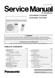
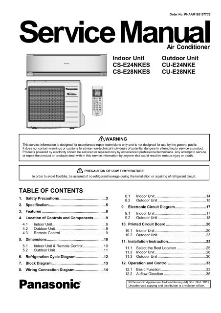
Order No: PHAAM1201077C2<br />
<strong>Indoor</strong> <strong>Unit</strong> <strong>Outdoor</strong> <strong>Unit</strong><br />
<strong>CS</strong>-<strong><strong>E24NKE</strong>S</strong><br />
<strong>CS</strong>-<strong>E28NKES</strong><br />
WARNING<br />
<strong>CU</strong>-<strong>E24NKE</strong><br />
<strong>CU</strong>-E28NKE<br />
This service information is designed for experienced repair technicians only and is not designed for use by the general public.<br />
It does not contain warnings or cautions to advise non-technical individuals of potential dangers in attempting to service a product.<br />
Products powered by electricity should be serviced or repaired only by experienced professional technicians. Any attempt to service<br />
or repair the product or products dealt with in this service information by anyone else could result in serious injury or death.<br />
PRECAUTION OF LOW TEMPERATURE<br />
In order to avoid frostbite, be assured of no refrigerant leakage during the installation or repairing of refrigerant circuit.<br />
8.1 <strong>Indoor</strong> <strong>Unit</strong>..................................................14<br />
8.2 <strong>Outdoor</strong> <strong>Unit</strong>...............................................15<br />
9. Electronic Circuit Diagram ..............................17<br />
9.1 <strong>Indoor</strong> <strong>Unit</strong>..................................................17<br />
9.2 <strong>Outdoor</strong> <strong>Unit</strong>...............................................18<br />
10. Printed Circuit Board .......................................20<br />
10.1 <strong>Indoor</strong> <strong>Unit</strong>..................................................20<br />
10.2 <strong>Outdoor</strong> <strong>Unit</strong>...............................................23<br />
11. Installation Instruction.....................................25<br />
11.1 Select the Best Location ............................25<br />
11.2 <strong>Indoor</strong> <strong>Unit</strong>..................................................26<br />
11.3 <strong>Outdoor</strong> <strong>Unit</strong>...............................................30<br />
12. Operation and Control .....................................33<br />
12.1 Basic Function............................................33<br />
12.2 Airflow Direction .........................................35<br />
© Panasonic Appliances Air-Conditioning (M) Sdn. Bhd. 2012.<br />
Unauthorized copying and distribution is a violation of law.
12.3 Quiet operation (Cooling Mode/Cooling area<br />
of Soft Dry Mode) .......................................37<br />
12.4 Powerful Mode Operation...........................38<br />
12.5 Timer Control..............................................38<br />
12.6 Auto Restart Control...................................38<br />
12.7 Indication Panel..........................................38<br />
12.8 nanoe-G Operation.....................................39<br />
12.9 Mild Dry Cooling Operation ........................41<br />
12.10 AUTO COMFORT and ECO NAVI<br />
Operation....................................................41<br />
13. Protection Control............................................50<br />
13.1 Protection Control For All Operations.........50<br />
13.2 Protection Control For Cooling & Soft Dry<br />
Operation....................................................52<br />
13.3 Protection Control For Heating<br />
Operation....................................................53<br />
14. Servicing Mode.................................................54<br />
14.1 Auto OFF/ON Button ..................................54<br />
14.2 Remote Control Button...............................55<br />
15. Troubleshooting Guide....................................56<br />
15.1 Refrigeration Cycle System........................56<br />
15.2 Relationship Between The Condition Of<br />
The Air Conditioner And Pressure And<br />
Electric Current...........................................57<br />
15.3 Breakdown Self Diagnosis Function...........58<br />
15.4 Error Codes Table ......................................59<br />
15.5 Self-diagnosis Method................................61<br />
16. Disassembly and Assembly Instructions ......89<br />
16.2 <strong>Outdoor</strong> Electronic Controller Removal<br />
Procedure ...................................................93<br />
17. Technical Data ..................................................94<br />
17.1 Operation Characteristics...........................94<br />
17.2 Sensible Capacity Chart.......................... 102<br />
18. Exploded View and Replacement Parts<br />
List .................................................................. 103<br />
18.1 <strong>Indoor</strong> <strong>Unit</strong> ............................................... 103<br />
18.2 <strong>Outdoor</strong> <strong>Unit</strong> ............................................ 106<br />
2
1. Safety Precautions<br />
� Read the following “SAFETY PRECAUTIONS” carefully before perform any servicing.<br />
� Electrical work must be installed or serviced by a licensed electrician. Be sure to use the correct rating of the<br />
power plug and main circuit for the model installed.<br />
� The caution items stated here must be followed because these important contents are related to safety. The<br />
meaning of each indication used is as below. Incorrect installation or servicing due to ignoring of the instruction<br />
will cause harm or damage, and the seriousness is classified by the following indications.<br />
WARNING<br />
CAUTION<br />
This indication shows the possibility of causing death or serious injury.<br />
This indication shows the possibility of causing injury or damage to properties.<br />
� The items to be followed are classified by the symbols:<br />
This symbol denotes item that is PROHIBITED from doing.<br />
� Carry out test run to confirm that no abnormality occurs after the servicing. Then, explain to user the operation,<br />
care and maintenance as stated in instructions. Please remind the customer to keep the operating instructions for<br />
future reference.<br />
1. Do not modify the machine, part, material during repairing service.<br />
WARNING<br />
2. If wiring unit is supplied as repairing part, do not repair or connect the wire even only partial wire break. Exchange the whole wiring unit.<br />
3. Do not wrench the fasten terminal. Pull it out or insert it straightly.<br />
4. Engage authorized dealer or specialist for installation and servicing. If installation or servicing done by the user is defective, it will cause<br />
water leakage, electrical shock or fire.<br />
5. Install according to this installation instructions strictly. If installation is defective, it will cause water leakage, electric shock or fire.<br />
6. Use the attached accessories parts and specified parts for installation and servicing. Otherwise, it will cause the set to fall, water leakage,<br />
fire or electrical shock.<br />
7. Install at a strong and firm location which is able to withstand the set’s weight. If the strength is not enough or installation is not properly done,<br />
the set will drop and cause injury.<br />
8. For electrical work, follow the local national wiring standard, regulation and the installation instruction. An independent circuit and single<br />
outlet must be used. If electrical circuit capacity is not enough or defect found in electrical work, it will cause electrical shock or fire.<br />
9. This equipment is strongly recommended to be installed with Earth Leakage Circuit Breaker (ELCB) or Residual Current Device (RCD).<br />
Otherwise, it may cause electrical shock and fire in case equipment breakdown or insulation breakdown.<br />
10. Do not use joint cable for indoor/outdoor connection cable. Use the specified indoor/outdoor connection cable, refer to installation instruction<br />
CONNECT THE CABLE TO THE INDOOR UNIT and connect tightly for indoor/outdoor connection. Clamp the cable so that no external force<br />
will be acted on the terminal. If connection or fixing is not perfect, it will cause heat up or fire at the connection.<br />
11. Wire routing must be properly arranged so that control board cover is fixed properly. If control board cover is not fixed perfectly, it will cause<br />
heat-up or fire at the connection point of terminal, fire or electrical shock.<br />
12. When install or relocate air conditioner, do not let any substance other than the specified refrigerant, eg. air etc. mix into refrigeration<br />
cycle (piping). (Mixing of air etc. will cause abnormal high pressure in refrigeration cycle and result in explosion, injury etc.).<br />
13. Do not install outdoor unit near handrail of veranda. When installing air-conditioner unit at veranda of high rise building, child may climb up to<br />
outdoor unit and cross over the handrail and causing accident.<br />
14. This equipment must be properly earthed. Earth line must not be connected to gas pipe, water pipe, earth of lightning rod and<br />
telephone. Otherwise, it may cause electric shock in case equipment breakdown or insulation breakdown.<br />
15. Keep away from small children, the thin film may cling to nose and mouth and prevent breathing.<br />
16. Do not use unspecified cord, modified cord, joint cord or extension cord for power supply cord. Do not share the single outlet with<br />
other electrical appliances. Poor contact, poor insulation or over current will cause electrical shock or fire.<br />
17. Tighten the flare nut with torque wrench according to specified method. If the flare nut is over-tightened, after a long period, the flare<br />
may break and cause refrigerant gas leakage.<br />
18. For R410A models, when connecting the piping, do not use any existing (R22) pipes and flare nuts. Using such same may cause<br />
abnormally high pressure in the refrigeration cycle (piping), and possibly result in explosion and injury. Use only R410A materials.<br />
Thickness of copper pipes used with R410A must be more than 0.8mm. Never use copper pipes thinner than 0.8mm.<br />
It is desirable that the amount of residual oil is less than 40 mg/10m.<br />
3
WARNING<br />
19. During installation, install the refrigerant piping properly before run the compressor. (Operation of compressor without fixing refrigeration piping<br />
and valves at opened condition will cause suck-in of air, abnormal high pressure in refrigeration cycle and result in explosion, injury etc).<br />
20. During pump down operation, stop the compressor before remove the refrigeration piping. (Removal of refrigeration piping while compressor is<br />
operating and valves are opened condition will cause suck-in of air, abnormal high pressure in refrigeration cycle and result in explosion,<br />
injury etc.)<br />
21. After completion of installation or service, confirm there is no leakage or refrigerant gas. It may generate toxic gas when the refrigerant<br />
contacts with fire.<br />
22. Ventilate if there is refrigerant gas leakage during operation. It may cause toxic gas when the refrigerant contacts with fire.<br />
23. Do not insert your fingers or other objects into the unit, high speed rotating fan may cause injury.<br />
24. Must not use other parts except original parts describe in catalog and manual.<br />
25. Using of refrigerant other than the specified type may cause product damage, burst and injury etc.<br />
CAUTION<br />
1. Do not install the unit at place where leakage of flammable gas may occur. In case gas leaks and accumulates at surrounding of the<br />
unit, it may cause fire.<br />
2. Carry out drainage piping as mentioned in installation instructions. If drainage is not perfect, water may enter the room and damage<br />
the furniture.<br />
3. Tighten the flare nut with torque wrench according to specified method. If the flare nut is over-tightened, after a long period, the flare<br />
may break and cause refrigerant gas leakage.<br />
4. Do not touch outdoor unit air inlet and aluminium fin. It may cause injury.<br />
5. Select an installation location which is easy for maintenance.<br />
6. Pb free solder has a higher melting point than standard solder; typically the melting point is 50°F – 70°F (30°C – 40°C) higher. Please use<br />
a high temperature solder iron. In case of the soldering iron with temperature control, please set it to 700 ± 20°F (370 ± 10°C).<br />
Pb free solder will tend to splash when heated too high (about 1100°F / 600°C).<br />
7. Power supply connection to the air conditioner. Connect the power supply cord of the air conditioner to the mains using one of the following<br />
methods.<br />
Power supply point shall be the place where there is ease for access for the power disconnection in case of emergency. In some countries,<br />
permanent connection of this room air conditioner to the power supply is prohibited.<br />
i. Power supply connection to the receptacle using a power plug. Use an approved 15/16A (3/4~1.75HP), 16A (2.0HP), 20A (2.5HP) or<br />
25A (3.0HP) power plug with earth pin for the connection to the socket.<br />
ii. Power supply connection to a circuit breaker for the permanent connection. Use an approved 16A (3/4~2.0HP), 20A (2.5HP) or<br />
25A (3.0HP) circuit breaker for the permanent connection. It must be a double pole switch with a minimum 3.0 mm contact gap.<br />
8. Do not release refrigerant during piping work for installation, servicing, reinstallation and during repairing a refrigerant parts.<br />
Take care of the liquid refrigerant, it may cause frostbite.<br />
9. Installation or servicing work: It may need two people to carry out the installation or servicing work.<br />
10. Do not install this appliance in a laundry room or other location where water may drip from the ceiling, etc.<br />
11. Do not sit or step on the unit, you may fall down accidentally.<br />
12. Do not touch the sharp aluminium fins or edges of metal parts.<br />
If you are required to handle sharp parts during installation or servicing, please wear hand glove.<br />
Sharp parts may cause injury.<br />
4
2. Specification<br />
Cooling<br />
Heating<br />
Model<br />
<strong>Indoor</strong> <strong>CS</strong>-<strong><strong>E24NKE</strong>S</strong> <strong>CS</strong>-<strong>E28NKES</strong><br />
<strong>Outdoor</strong> <strong>CU</strong>-<strong>E24NKE</strong> <strong>CU</strong>-E28NKE<br />
Performance Test Condition EUROVENT EUROVENT<br />
Power Supply<br />
Phase, Hz Single, 50 Single, 50<br />
V 230 230<br />
Min. Mid. Max. Min. Mid. Max.<br />
kW 0.98 6.80 8.10 0.98 7.65 8.60<br />
Capacity<br />
BTU/h 3340 23200 27600 3340 26100 29300<br />
Kcal/h 840 5850 6970 840 6580 7400<br />
Running Current A - 9.7 - - 11.5 -<br />
Input Power W 380 2.12k 2.70k 380 2.54k 2.95k<br />
Annual Consumption kWh - 1060 - - 1270 -<br />
W/W 2.58 3.21 3.00 2.58 3.01 2.92<br />
EER<br />
BTU/hw 8.79 10.94 10.22 8.79 10.28 9.93<br />
Kcal/hW 2.21 2.76 2.58 2.21 2.59 2.51<br />
Power Factor % - 95 - - 96 -<br />
<strong>Indoor</strong> Noise (H / L / QLo)<br />
dB-A 47 / 38 / 35 49 / 38 / 35<br />
Power Level dB 63 / - 65 / -<br />
<strong>Outdoor</strong> Noise (H / L)<br />
dB-A 52 / - 53 / -<br />
Power Level dB 66 / - 67 / -<br />
kW 0.98 8.60 9.90 0.98 9.60 11.00<br />
Capacity<br />
BTU/h 3340 29300 33800 3340 32700 37500<br />
Kcal/h 840 7400 8510 840 8260 9460<br />
Running Current A - 12.1 - - 15.0 -<br />
Input Power W 450 2.66k 3.20k 450 3.30k 3.75k<br />
W/W 2.18 3.23 3.09 2.18 2.91 2.93<br />
COP<br />
BTU/hW 7.42 11.02 10.56 7.42 9.91 10.00<br />
Kcal/hW 1.87 2.78 2.66 1.87 2.50 2.52<br />
Power Factor % - 96 - - 96 -<br />
<strong>Indoor</strong> Noise (H / L / QLo)<br />
dB-A<br />
Power Level dB<br />
47 / 38 / 35<br />
63 / -<br />
48 / 38 / 35<br />
64 / -<br />
<strong>Outdoor</strong> Noise (H / L)<br />
dB-A 52 / - 53 / -<br />
Power Level dB 66 / - 67 / -<br />
Low Temp. : Capacity (kW) / I.Power (W) / COP 7.17 / 2.83k / 2.53 7.97 / 3.32k / 2.40<br />
Extr Low Temp. : Capacity (kW) / I.Power (W) / COP 6.13 / 2.86k / 2.14 6.77 / 3.47k / 1.95<br />
Compressor<br />
Max Current (A) / Max Input Power (W) 14.6 / 3.20k 15.6 / 3.75k<br />
Starting Current (A) 12.1 15.0<br />
Type Hermetic Motor (Rotary) Hermetic Motor (Rotary)<br />
Motor Type Brushless (4 poles) Brushless (4 poles)<br />
Output Power W 1.7k 1.7k<br />
5
<strong>Indoor</strong> Fan<br />
<strong>Outdoor</strong> Fan<br />
Speed<br />
Type Cross-Flow Fan Cross-Flow Fan<br />
Material ASG20K1 ASG20K1<br />
Motor Type Transistor (8-poles) Transistor (8-poles)<br />
Input Power W 94.8 94.8<br />
Output Power W 40 40<br />
QLo<br />
Lo<br />
Me<br />
Hi<br />
Shi<br />
Cool rpm 900 900<br />
Heat rpm 990 990<br />
Cool rpm 1000 1000<br />
Heat rpm 1090 1090<br />
Cool rpm 1200 1230<br />
Heat rpm 1280 1320<br />
Cool rpm 1410 1470<br />
Heat rpm 1480 1550<br />
Cool rpm 1480 1520<br />
Heat rpm 1520 1570<br />
Type Propeller Fan Propeller Fan<br />
Material PP PP<br />
Motor Type Induction (6-poles) Induction (6-poles)<br />
Input Power W - -<br />
Output Power W 80 80<br />
Speed Hi<br />
<strong>Indoor</strong><br />
Airflow<br />
<strong>Outdoor</strong><br />
Airflow<br />
Refrigeration<br />
Cycle<br />
Cool rpm 670 710<br />
Heat rpm - -<br />
Moisture Removal L/h (Pt/h) 3.9 (8.2) 4.5 (9.5)<br />
QLo<br />
Lo<br />
Me<br />
Hi<br />
Shi<br />
Hi<br />
Cool m 3 /min (ft 3 /min) 10.40 (367) 10.40 (367)<br />
Heat m 3 /min (ft 3 /min) 11.35 (401) 11.35 (401)<br />
Cool m 3 /min (ft 3 /min) 11.95 (422) 11.95 (422)<br />
Heat m 3 /min (ft 3 /min) 12.90 (456) 12.90 (456)<br />
Cool m 3 /min (ft 3 /min) 15.20 (537) 15.60 (551)<br />
Heat m 3 /min (ft 3 /min) 16.45 (581) 16.50 (583)<br />
Cool m 3 /min (ft 3 /min) 18.4 (650) 19.3 (680)<br />
Heat m 3 /min (ft 3 /min) 19.5 (690) 20.1 (710)<br />
Cool m 3 /min (ft 3 /min) 19.4 (685) 20.1 (710)<br />
Heat m 3 /min (ft 3 /min) 20.1 (710) 20.6 (727)<br />
Cool m 3 /min (ft 3 /min) 50.2 (1770) 54.5 (1925)<br />
Heat m 3 /min (ft 3 /min) 50.2 (1770) 54.5 (1925)<br />
Control Device Capillary Tube Expansion Valve<br />
Refrigerant Oil cm 3 FV50S (800) FV50S (800)<br />
Refrigerant Type g (oz) R410A, 1.70k (60.0) R410A, 1.80k (63.5)<br />
Height (I/D / O/D) mm (inch) 240 (9-15/32) / 795 (31-5/16) 240 (9-15/32) / 795 (31-5/16)<br />
Dimension Width (I/D / O/D) mm (inch) 1070 (42-5/32) / 875 (34-15/32) 1070 (42-5/32) / 875 (34-15/32)<br />
Depth (I/D / O/D) mm (inch) 240 (9-15/32) / 320 (12-5/8) 240 (9-15/32) / 320 (12-5/8)<br />
Weight Net (I/D / O/D) kg (lb) 12 (26) / 65 (143) 12 (26) / 67 (148)<br />
Pipe Diameter (Liquid / Gas) mm (inch) 6.35 (1/4) / 15.88 (5/8) 6.35 (1/4) / 15.88 (5/8)<br />
Piping<br />
Standard Length m (ft) 5.0 (16.4) 5.0 (16.4)<br />
Length Range (min – max) m (ft) 3 (9.8) ~ 30 (98.4) 3 (9.8) ~ 30 (98.4)<br />
I/D & O/D Height Different m (ft) 20 (65.6) 20 (65.6)<br />
Additional Gas Amount g/m (oz/ft) 30 (0.3) 30 (0.3)<br />
Length for Additional Gas m (ft) 10 (32.8) 10 (32.8)<br />
6
Drain Hose<br />
<strong>Indoor</strong> Heat<br />
Exchanger<br />
<strong>Outdoor</strong><br />
Heat<br />
Exchanger<br />
Air Filter<br />
Inner Diameter mm 16.7 16.7<br />
Length mm 650 650<br />
Fin Material Aluminium (Pre Coat) Aluminium (Pre Coat)<br />
Fin Type Slit Fin Slit Fin<br />
Row x Stage x FPI 2 x 15 x 21 2 x 15 x 21<br />
Size (W x H x L) mm 810 x 315 x 25.4 810 x 315 x 25.4<br />
Fin Material Aluminium (Pre Coat) Aluminium (Pre Coat)<br />
Fin Type Corrugated Fin Corrugated Fin<br />
Row x Stage x FPI 2 x 30 x 19 2 x 30 x 19<br />
Size (W x H x L) mm 38.1 x 762 x 895.8:865.8 38.1 x 762 x 895.8:865.8<br />
Material Polypropelene Polypropelene<br />
Type One-touch One-touch<br />
Power Supply <strong>Outdoor</strong> Power Supply <strong>Outdoor</strong> Power Supply<br />
Power Supply Cord A Nil Nil<br />
Thermostat Electronic Contol Electronic Contol<br />
Protection Device Electronic Contol Electronic Contol<br />
<strong>Indoor</strong><br />
Operation<br />
Range<br />
<strong>Outdoor</strong><br />
Operation<br />
Range<br />
Cooling<br />
Heating<br />
Cooling<br />
Heating<br />
Dry Bulb Wet Bulb Dry Bulb Wet Bulb<br />
Maximum 32 23 32 23<br />
Minimum 16 11 16 11<br />
Maximum 30 - 30 -<br />
Minimum 16 - 16 -<br />
Maximum 43 26 43 26<br />
Minimum 16 11 16 11<br />
Maximum 24 18 24 18<br />
Minimum -5 -6 -5 -6<br />
1. Cooling capacities are based on indoor temperature of 27°C Dry Bulb (80.6°F Dry Bulb), 19.0°C Wet Bulb (66.2°F Wet Bulb) and outdoor air<br />
temperature of 35°C Dry Bulb (95°F Dry Bulb), 24°C Wet Bulb (75.2°F Wet Bulb)<br />
2. Heating capacities are based on indoor temperature of 20°C Dry Bulb (68°F Dry Bulb) and outdoor air temperature of 7°C Dry Bulb<br />
(44.6°F Dry Bulb), 6°C Wet Bulb (42.8°F Wet Bulb)<br />
3. Heating low temperature capacity, Input Power and COP measured at 230 V, indoor temperature 20°C, outdoor 2/1°C.<br />
4. Heating extreme low temperature capacity, Input Power and COP measured at 230 V, indoor temperature 20°C, outdoor -7/-8°C.<br />
5. Specifications are subjected to change without prior notice for further improvement.<br />
7
3. Features<br />
� Inverter Technology<br />
o Wider output power range<br />
o Energy saving<br />
o Quick Cooling<br />
o More precise temperature control<br />
� Environment Protection<br />
o Non-ozone depletion substances refrigerant (R410A)<br />
� Long Installation Piping<br />
o <strong>CS</strong>/<strong>CU</strong>-E24/28NK, long piping up to 30 meter<br />
� Easy to use remote control<br />
� Quality Improvement<br />
o Random auto restart after power failure for safety restart operation<br />
o Gas leakage protection<br />
o Prevent compressor reverse cycle<br />
o Inner protector to protect compressor<br />
o Noise prevention during soft dry operation<br />
� Operation Improvement<br />
o Quiet mode to reduce the indoor unit operating sound<br />
o Powerful mode to reach the desired room temperature quickly<br />
o 24-hour timer setting<br />
� Serviceability Improvement<br />
o Breakdown Self Diagnosis function<br />
8
4. Location of Controls and Components<br />
4.1 <strong>Indoor</strong> <strong>Unit</strong><br />
4.2 <strong>Outdoor</strong> <strong>Unit</strong><br />
4.3 Remote Control<br />
9
5. Dimensions<br />
5.1 <strong>Indoor</strong> <strong>Unit</strong> & Remote Control<br />
10
5.2 <strong>Outdoor</strong> <strong>Unit</strong><br />
11
6. Refrigeration Cycle Diagram<br />
12
7. Block Diagram<br />
13
8. Wiring Connection Diagram<br />
8.1 <strong>Indoor</strong> <strong>Unit</strong><br />
14
8.2 <strong>Outdoor</strong> <strong>Unit</strong><br />
8.2.1 <strong>CU</strong>-<strong>E24NKE</strong><br />
15
8.2.2 <strong>CU</strong>-E28NKE<br />
16
9. Electronic Circuit Diagram<br />
9.1 <strong>Indoor</strong> <strong>Unit</strong><br />
17
9.2 <strong>Outdoor</strong> <strong>Unit</strong><br />
9.2.1 <strong>CU</strong>-<strong>E24NKE</strong><br />
18
9.2.2 <strong>CU</strong>-E28NKE<br />
19
10. Printed Circuit Board<br />
10.1 <strong>Indoor</strong> <strong>Unit</strong><br />
10.1.1 Main Printed Circuit Board<br />
10.1.2 Indicator Printed Circuit Board<br />
20
10.1.3 High Voltage Power Supply Printed Circuit Board<br />
10.1.4 Comparator Printed Circuit Board<br />
21
10.1.5 Human Activity Sensor Printed Circuit Board<br />
22
10.2 <strong>Outdoor</strong> <strong>Unit</strong><br />
10.2.1 Main Printed Circuit Board<br />
23
10.2.2 Power Printed Circuit Board<br />
24
11. Installation Instruction<br />
11.1 Select the Best Location<br />
11.1.1 <strong>Indoor</strong> <strong>Unit</strong><br />
� Do not install the unit in excessive oil fume area<br />
such as kitchen, workshop and etc.<br />
� There should not be any heat source or steam<br />
near the unit.<br />
� There should not be any obstacles blocking the air<br />
circulation.<br />
� A place where air circulation in the room is good.<br />
� A place where drainage can be easily done.<br />
� A place where noise prevention is taken into<br />
consideration.<br />
� Do not install the unit near the door way.<br />
� Ensure the spaces indicated by arrows from the<br />
wall, ceiling, fence or other obstacles.<br />
� Recommended installation height for indoor unit<br />
shall be at least 2.5 m.<br />
11.1.2 <strong>Outdoor</strong> <strong>Unit</strong><br />
� If an awning is built over the unit to prevent direct<br />
sunlight or rain, be careful that heat radiation from<br />
the condenser is not obstructed.<br />
� There should not be any animal or plant which<br />
could be affected by hot air discharged.<br />
� Keep the spaces indicated by arrows from wall,<br />
ceiling, fence or other obstacles.<br />
� Do not place any obstacles which may cause a<br />
short circuit of the discharged air.<br />
� If piping length is over the [piping length for<br />
additional gas], additional refrigerant should be<br />
added as shown in the table.<br />
Model<br />
Horse<br />
Power<br />
(HP)<br />
Piping size<br />
Gas Liquid<br />
Std.<br />
Length<br />
(m)<br />
Max.<br />
Elevation<br />
(m)<br />
Min.<br />
Piping<br />
Length<br />
(m)<br />
Max.<br />
Piping<br />
Length<br />
(m)<br />
AdditionalRefri-<br />
gerant<br />
(g/m)<br />
Piping<br />
Lengt<br />
h for<br />
add.<br />
gas<br />
(m)<br />
E7***,<br />
3/4HP<br />
XE7***<br />
E9***,<br />
1.0HP<br />
XE9***<br />
E12***,<br />
XE12***<br />
15<br />
15<br />
15<br />
15<br />
20<br />
20<br />
7.5<br />
7.5<br />
1.5HP<br />
9.52<br />
mm<br />
(3/8")<br />
15 15 20 7.5<br />
E15***,<br />
1.75HP<br />
XE15***<br />
E18***,<br />
2.0HP<br />
XE18***<br />
E21***,<br />
XE21***<br />
15<br />
15<br />
15<br />
20<br />
20<br />
20<br />
7.5<br />
7.5<br />
2.25HP<br />
6.35<br />
12.7 mm<br />
mm (1/4")<br />
(1/2")<br />
5<br />
15<br />
3<br />
20 20 7.5<br />
E24*** 2.5HP 15.88<br />
mm<br />
20 30 30 10<br />
E28*** 3.0HP (5/8")<br />
20<br />
30 30 10<br />
Example: For E9***<br />
If the unit is installed at 10 m distance, the quantity of<br />
additional refrigerant should be 50 g .... (10-7.5) m x<br />
20 g/m = 50 g.<br />
25<br />
11.1.3 <strong>Indoor</strong>/<strong>Outdoor</strong> <strong>Unit</strong> Installation<br />
Diagram
11.2 <strong>Indoor</strong> <strong>Unit</strong><br />
11.2.1 How to Fix Installation Plate<br />
The mounting wall shall be strong and solid enough to<br />
prevent it from the vibration.<br />
The center of installation plate should be at more than<br />
� at right and left of the wall.<br />
The distance from installation plate edge to ceiling<br />
should more than �.<br />
From installation plate left edge to unit’s left side is �.<br />
From installation plate right edge to unit’s right side is<br />
�.<br />
○B : For left side piping, piping connection for<br />
liquid should be about � from this line.<br />
: For left side piping, piping connection for gas<br />
should be about � from this line.<br />
1 Mount the installation plate on the wall with<br />
5 screws or more (at least 5 screws).<br />
(If mounting the unit on the concrete wall,<br />
consider using anchor bolts.)<br />
o Always mount the installation plate<br />
horizontally by aligning the marking-off<br />
line with the thread and using a level<br />
gauge.<br />
2 Drill the piping plate hole with ø70 mm holecore<br />
drill.<br />
o Line according to the left and right side of<br />
the installation plate. The meeting point<br />
of the extended line is the center of the<br />
hole. Another method is by putting<br />
measuring tape at position as shown in<br />
the diagram above. The hole center is<br />
obtained by measuring the distance<br />
namely 128 mm for left and right hole<br />
respectively.<br />
o Drill the piping hole at either the right or<br />
the left and the hole should be slightly<br />
slanting to the outdoor side.<br />
26<br />
11.2.2 To Drill a Hole in the Wall and<br />
Install a Sleeve of Piping<br />
1 Insert the piping sleeve to the hole.<br />
2 Fix the bushing to the sleeve.<br />
3 Cut the sleeve until it extrudes about 15 mm<br />
from the wall.<br />
4 Finish by sealing the sleeve with putty or<br />
caulking compound at the final stage.<br />
11.2.3 <strong>Indoor</strong> <strong>Unit</strong> Installation
11.2.3.1 For the right rear piping<br />
11.2.3.2 For the right and right<br />
bottom piping<br />
11.2.3.3 For the embedded piping<br />
27<br />
(This can be used for left rear piping and bottom<br />
piping also.)
11.2.4 Connect the Cable to the <strong>Indoor</strong> <strong>Unit</strong><br />
1 The inside and outside connection cable can<br />
be connected without removing the front grille.<br />
2 Connection cable between indoor unit and<br />
outdoor unit shall be approved<br />
polychloroprene sheathed 4 x 1.5 mm 2 flexible<br />
cord, type designation 245 IEC 57 or heavier<br />
cord.<br />
3 Bind all the indoor and outdoor connection<br />
cable with tape and route the connection<br />
cable via the escapement.<br />
4 Remove the tapes and connect the<br />
connection cable between indoor unit and<br />
outdoor unit according to the diagram below.<br />
Note:<br />
o Secure the connecting cable onto the control board with the holder (clamper).<br />
o Ensure the colour of wires of outdoor unit and the terminal Nos. are the same to the indoor’s<br />
respectively.<br />
o Earth wire shall be Yellow/Green (Y/G) in colour and longer than other AC wires for safety reason.<br />
28
11.2.4.1 Cutting and flaring the piping<br />
1 Please cut using pipe cutter and then remove the burrs.<br />
2 Remove the burrs by using reamer. If burrs is not removed, gas leakage may be caused.<br />
Turn the piping end down to avoid the metal powder entering the pipe.<br />
3 Please make flare after inserting the flare nut onto the copper pipes.<br />
29
11.3 <strong>Outdoor</strong> <strong>Unit</strong><br />
11.3.1 Install the <strong>Outdoor</strong> <strong>Unit</strong><br />
� After selecting the best location, start installation according to <strong>Indoor</strong>/<strong>Outdoor</strong> <strong>Unit</strong> Installation Diagram.<br />
1 Fix the unit on concrete or rigid frame firmly and horizontally by bolt nut (ø10 mm).<br />
2 When installing at roof, please consider strong wind and earthquake. Please fasten the installation stand<br />
firmly with bolt or nails.<br />
11.3.2 Connect the Piping<br />
Connecting the Piping to <strong>Indoor</strong><br />
Please make flare after inserting flare nut (locate at<br />
joint portion of tube assembly) onto the copper pipe.<br />
(In case of using long piping)<br />
Connect the piping<br />
� Align the center of piping and sufficiently tighten<br />
the flare nut with fingers.<br />
� Further tighten the flare nut with torque wrench in<br />
specified torque as stated in the table.<br />
Connecting the Piping to <strong>Outdoor</strong><br />
Decide piping length and then cut by using pipe cutter.<br />
Remove burrs from cut edge. Make flare after<br />
inserting the flare nut (locate at valve) onto the copper<br />
pipe.<br />
Align center of piping to valves and then tighten with<br />
torque wrench to the specified torque as stated in the<br />
table.<br />
30<br />
Model A B C D<br />
E7***<br />
E9***<br />
E12***-3<br />
570 mm 105 mm 18.5 mm 320 mm<br />
E12***<br />
E15***<br />
E15***-3<br />
E18***<br />
540 mm 160 mm 18.5 mm 330 mm<br />
E21***<br />
E24***<br />
E28***<br />
613 mm 131 mm 16 mm 360.5 mm<br />
Do not over tighten, over tightening cause gas leakage.<br />
Piping Size Torque<br />
6.35 mm (1/4”) [18 N•m (1.8 kgf.m)]<br />
9.52 mm (3/8”) [42 N•m (4.3 kgf.m)]<br />
12.7 mm (1/2”) [55 N•m (5.6 kgf.m)]<br />
15.88 mm (5/8”) [65 N•m (6.6 kgf.m)]<br />
19.05 mm (3/4”) [100 N•m (10.2 kgf.m)]<br />
Connecting the Piping to <strong>Outdoor</strong> Multi<br />
Decide piping length and then cut by using pipe cutter. Remove burrs from cut edge. Make flare after inserting the<br />
flare nut (located at valve) onto the copper pipe.<br />
Align center of piping to valve and then tighten with torque wrench to the specified torque as stated in the table.
11.3.3 Evacuation of the Equipment<br />
WHEN INSTALLING AN AIR CONDITIONER, BE SURE TO EVA<strong>CU</strong>ATE THE AIR INSIDE THE INDOOR UNIT AND<br />
PIPES in the following procedure.<br />
1 Connect a charging hose with a push pin to the Low side of a charging set and the service port of the 3-way<br />
valve.<br />
o Be sure to connect the end of the charging hose with the push pin to the service port.<br />
2 Connect the center hose of the charging set to a vacuum pump.<br />
3 Turn on the power switch of the vacuum pump and make sure that the needle in the gauge moves from<br />
0 cmHg (0 MPa) to -76 cmHg (-0.1 MPa). Then evacuate the air approximately ten minutes.<br />
4 Close the Low side valve of the charging set and turn off the vacuum pump. Make sure that the needle in the<br />
gauge does not move after approximately five minutes.<br />
Note: BE SURE TO TAKE THIS PROCEDURE IN ORDER TO AVOID REFRIGERENT GAS LEAKAGE.<br />
5 Disconnect the charging hose from the vacuum pump and from the service port of the 3-way valve.<br />
6 Tighten the service port caps of the 3-way valve at a torque of 18 N•m with a torque wrench.<br />
7 Remove the valve caps of both of the 2-way valve and 3-way valve. Position both of the valves to “OPEN”<br />
using a hexagonal wrench (4 mm).<br />
8 Mount valve caps onto the 2-way valve and the 3-way valve.<br />
o Be sure to check for gas leakage.<br />
� If gauge needle does not move from 0 cmHg (0 MPa) to -76 cmHg (-0.1 MPa), in the step � above take the following measure:<br />
- If the leak stops when the piping connections are tightened further, continue working from step �.<br />
- If the leak does not stop when the connections are retightened, repair location of leak.<br />
- Do not release refrigerant during piping work for installation and reinstallation.<br />
- Take care of the liquid refrigerant, it may cause frostbite.<br />
11.3.4 Connect the Cable to the <strong>Outdoor</strong> <strong>Unit</strong><br />
1 Remove the control board cover from the unit<br />
by loosening the screw.<br />
2 Cable connection to the power supply through<br />
Isolating Devices (Disconnecting means).<br />
o Connect approved type polychloroprene<br />
sheathed power supply cord 3 x<br />
1.5 mm 2 (3/4 ~ 1.75HP), 3 x 2.5 mm 2<br />
(2.0 ~ 2.5HP) or 3 x 4.0 mm 2 (3.0HP)<br />
type designation 245 IEC 57 or heavier<br />
cord to the terminal board, and connect<br />
the others end of the cord to Isolating<br />
Devices (Disconnecting means).<br />
3 Connection cable between indoor unit and<br />
outdoor unit shall be approved<br />
polychloroprene sheathed 4 x 1.5 mm 2 flexible<br />
cord, type designation 245 IEC 57 or heavier<br />
cord.<br />
4 Connect the power supply cord and<br />
connection cable between indoor unit and<br />
outdoor unit according to the diagram below.<br />
31
5 Secure the power supply cord and connection cable onto the control board with the holder.<br />
6 Attach the control board cover back to the original position with screw.<br />
7 For wire stripping and connection requirement, refer to instruction 11.2.4 of indoor unit.<br />
WARNING<br />
This equipment must be properly earthed.<br />
� Note: Isolating Devices (Disconnecting means) should have minimum 3.0 mm contact gap.<br />
� Earth wire shall be Yellow/Green (Y/G) in colour and longer than other AC wires for safety reason.<br />
11.3.5 Piping Insulation<br />
1 Please carry out insulation at pipe connection portion as mentioned in <strong>Indoor</strong>/<strong>Outdoor</strong> <strong>Unit</strong> Installation<br />
Diagram. Please wrap the insulated piping end to prevent water from going inside the piping.<br />
2 If drain hose or connecting piping is in the room (where dew may form), please increase the insulation by<br />
using POLY-E FOAM with thickness 6 mm or above.<br />
32
12. Operation and Control<br />
12.1 Basic Function<br />
Inverter control, which equipped with a microcomputer in determining the most suitable operating mode as time<br />
passes, automatically adjusts output power for maximum comfort always. In order to achieve the suitable operating<br />
mode, the microcomputer maintains the set temperature by measuring the temperature of the environment and<br />
performing temperature shifting. The compressor at outdoor unit is operating following the frequency instructed by<br />
the microcomputer at indoor unit that judging the condition according to internal setting temperature and intake air<br />
temperature.<br />
12.1.1 Internal Setting Temperature<br />
Once the operation starts, remote control setting temperature will be taken as base value for temperature shifting<br />
processes. These shifting processes are depending on the air conditioner settings and the operation environment.<br />
The final shifted value will be used as internal setting temperature and it is updated continuously whenever the<br />
electrical power is supplied to the unit.<br />
12.1.2 Cooling Operation<br />
12.1.2.1 Thermostat control<br />
� Compressor is OFF when Intake Air Temperature - Internal Setting Temperature < -1.5°C continue for 3 minutes.<br />
� Compressor is ON after waiting for 3 minutes, if the Intake Air Temperature - Internal Setting Temperature ><br />
Compressor OFF point.<br />
12.1.3 Soft Dry Operation<br />
12.1.3.1 Thermostat control<br />
� Compressor is OFF when Intake Air Temperature - Internal Setting Temperature < -2.0°C continue for 3 minutes.<br />
� Compressor is ON after waiting for 3 minutes, if the Intake Air Temperature - Internal Setting Temperature ><br />
Compressor OFF point.<br />
12.1.4 Heating Operation<br />
12.1.4.1 Thermostat control<br />
� Compressor is OFF when Intake Air Temperature - Internal Setting Temperature > +2.0°C continue for 3 minutes.<br />
� Compressor is ON after waiting for 3 minutes, if the Intake Air Temperature - Internal Setting Temperature <<br />
Compressor OFF point.<br />
33
12.1.5 Automatic Operation<br />
� This mode can be set using remote control and the operation is decided by remote control setting temperature,<br />
remote control operation mode and indoor intake air temperature.<br />
� During operation mode judgment, indoor fan motor (with speed of Lo-) is running for 30 seconds to detect the<br />
indoor intake air temperature.<br />
� Every 10 minutes, the indoor temperature is judged.<br />
� For the 1st judgment<br />
o If indoor intake temperature - remote control setting temperature ≥ 2°C, COOL mode is decided.<br />
o If -2°C ≤ indoor intake temperature - remote control setting temperature < 2°C, DRY mode is decided.<br />
o If indoor intake temperature - remote control setting temperature < -2°C, HEAT mode is decided.<br />
� For the 2nd judgment onwards<br />
o If indoor intake temperature - remote control setting temperature ≥ 3°C, if previous operate in DRY mode,<br />
then continue in DRY mode. otherwise COOL mode is decided.<br />
o If -2°C ≤ indoor intake temperature - remote control setting temperature < 3°C, maintain with previous mode.<br />
o If indoor intake temperature - remote control setting temperature < -2°C, HEAT mode is decided.<br />
12.1.6 <strong>Indoor</strong> Fan Motor Operation<br />
A. Basic Rotation Speed (rpm)<br />
i. Manual Fan Speed<br />
[Cooling, Dry]<br />
� Fan motor’s number of rotation is determined according to remote control setting.<br />
Remote control ○ ○ ○ ○ ○<br />
Tab Hi Me+ Me Me- Lo<br />
[Heating]<br />
� Fan motor’s number of rotation is determined according to remote control setting.<br />
Remote control ○ ○ ○ ○ ○<br />
Tab SHi Me+ Me Me- Lo<br />
ii. Auto Fan Speed<br />
[Cooling, Dry]<br />
� According to room temperature and setting temperature, indoor fan speed is determined automatically.<br />
� The indoor fan will operate according to pattern below.<br />
34
[Heating]<br />
o According to indoor pipe temperature, automatic heating fan speed is determined as follows.<br />
B. Feedback control<br />
� Immediately after the fan motor started, feedback control is performed once every second.<br />
� During fan motor on, if fan motor feedback ≥ 2550 rpm or < 50 rpm continue for 10 seconds, then fan motor error<br />
counter increase, fan motor is then stop and restart. If the fan motor counter becomes 7 times, then H19 - fan<br />
motor error is detected. Operation stops and cannot on back.<br />
12.1.7 <strong>Outdoor</strong> Fan Motor Operation<br />
<strong>Outdoor</strong> fan motor is operated with one fan speed only. It starts when compressor starts operation and it stops<br />
30 seconds after compressor stops operation.<br />
12.2 Airflow Direction<br />
� There are two types of airflow, vertical airflow (directed by horizontal vane) and horizontal airflow (directed by<br />
vertical vanes).<br />
� Control of airflow direction can be automatic (angles of direction is determined by operation mode, heat<br />
exchanger temperature and intake air temperature) and manual (angles of direction can be adjusted using<br />
remote control).<br />
12.2.1 Vertical Airflow<br />
Cooling<br />
Dry<br />
Operation Mode<br />
Auto<br />
Manual<br />
Auto<br />
Manual<br />
35<br />
Vane Angle (°)<br />
1 2 3 4 5<br />
Usual (Ventilation) 5 ~ 35<br />
Control with dew 5 ~ 35<br />
Usual (Ventilation) 5 12.5 20 27.5 35<br />
Control with dew 5 12.5 20 27.5 35<br />
Usual 5 ~ 35<br />
Control with dew 5 ~ 35<br />
Usual 5 12.5 20 27.5 35<br />
Control with dew 5 12.5 20 27.5 35<br />
Heating Manual Usual 5 17.5 30 42.5 55<br />
1 Automatic vertical airflow direction can be set using remote control; the vane swings up and down within the<br />
angles as stated above. For heating mode operation, the angle of the vane depends on the indoor heat<br />
exchanger temperature as Figure 1 below. It does not swing during fan motor stop. When the air conditioner<br />
is stopped using remote control, the vane will shift to close position.
2 Manual vertical airflow direction can be set using remote control; the angles of the vane are as stated above<br />
and the positions of the vane are as Figure 2 below. When the air conditioner is stopped using remote control,<br />
the vane will shift to close position.<br />
12.2.2 Horizontal Airflow<br />
1 Automatic horizontal airflow direction can be set using remote control; the vane swings left and right within<br />
the angles as stated below. It does not swing during fan motor stop. For heating mode operation, the angle of<br />
the vane depends on the indoor heat exchanger temperature as Figure 1 below.<br />
Operation Mode Vane Angle (°)<br />
Heating, with heat exchanger temperature<br />
A<br />
B<br />
65 ~ 115<br />
90<br />
Cooling and Soft Dry 65 ~ 115<br />
2 Manual horizontal airflow direction can be set using remote control; the angles of the vane are as stated<br />
below and the positions of the vane are as Figure 2 above.<br />
Pattern<br />
Airflow Direction<br />
Patterns at Remote<br />
Control<br />
1 2 3 4 5<br />
Vane Angle (°) 90 70 80 100 110<br />
36
12.3 Quiet operation (Cooling Mode/Cooling area of Soft Dry Mode)<br />
A. Purpose<br />
To provide quiet cooling operation compare to normal operation.<br />
B. Control condition<br />
a. Quiet operation start condition<br />
o When “POWERFUL/QUIET” button at remote control is pressed twice.<br />
POWERFUL/QUIET LED illuminates.<br />
b. Quiet operation stop condition<br />
1 When one of the following conditions is satisfied, quiet operation stops:<br />
a. POWERFUL/QUIET button is pressed again.<br />
b. Stop by OFF/ON switch.<br />
c. Timer “off” activates.<br />
d. AUTO COMFORT button is pressed.<br />
e. ECONAVI button is pressed.<br />
f. Mild Dry Cooling button is pressed.<br />
2 When quiet operation is stopped, operation is shifted to normal operation with previous setting.<br />
3 When fan speed is changed, quiet operation is shifted to quiet operation of the new fan speed.<br />
4 When operation mode is changed, quiet operation is shifted to quiet operation of the new mode.<br />
5 During quiet operation, if timer “on” activates, quiet operation maintains.<br />
6 After off, when on back, quiet operation is not memorised.<br />
C. Control contents<br />
1 Fan speed is changed from normal setting to quiet setting of respective fan speed.<br />
This is to reduce sound of Hi, Me, Lo for 3dB (some models more than 3dB).<br />
2 Fan speed for quiet operation is reduced from setting fan speed.<br />
12.3.1 Quiet operation (Heating)<br />
A. Purpose<br />
To provide quiet heating operation compare to normal operation.<br />
B. Control condition<br />
a. Quiet operation start condition<br />
o When “POWERFUL/QUIET” button at remote control is pressed.<br />
POWERFUL/QUIET LED.<br />
b. Quiet operation stop condition<br />
1 When one of the following conditions is satisfied, quiet operation stops:<br />
a. POWERFUL/QUIET button is pressed again.<br />
b. Stop by OFF/ON switch.<br />
c. Timer “off” activates.<br />
d. AUTO COMFORT button is pressed.<br />
e. ECONAVI button is pressed.<br />
f. Mild Dry Cooling button is pressed.<br />
2 When quiet operation is stopped, operation is shifted to normal operation with previous setting.<br />
3 When fan speed is changed, quiet operation is shifted to quiet operation of the new fan speed.<br />
4 When operation mode is changed, quiet operation is shifted to quiet operation of the new mode, except fan<br />
only mode.<br />
5 During quiet operation, if timer “on” activates, quiet operation maintains.<br />
6 After off, when on back, quiet operation is not memorised.<br />
C. Control contents<br />
a. Fan Speed manual<br />
1 Fan speed is changed from normal setting to quiet setting of respective fan speed.<br />
This is to reduce sound of Hi, Me, Lo for 3dB.<br />
2 Fan speed for quiet operation is reduced from setting fan speed.<br />
b. Fan Speed Auto<br />
1 <strong>Indoor</strong> FM RPM depends on pipe temp sensor of indoor heat exchanger.<br />
37
12.4 Powerful Mode Operation<br />
When the powerful mode is selected, the internal setting temperature will shift higher up to 3.5°C (for Heating) or<br />
lower up to 2°C (for Cooling/Soft Dry) than remote control setting temperature for 20 minutes to achieve the setting<br />
temperature quickly.<br />
12.5 Timer Control<br />
� There are 2 sets of ON and OFF timer available to turn the unit ON or OFF at different preset time.<br />
� If more than one timer had been set, the upcoming timer will be displayed and will activate in sequence.<br />
12.5.1 ON Timer Control<br />
� ON timer 1 and ON timer 2 can be set using remote control, the unit with timer set will start operate earlier than<br />
the setting time.<br />
This is to provide a comfortable environment when reaching the set ON time.<br />
� 60 minutes before the set time, indoor (at fan speed of Lo-) and outdoor fan motor start operate for 30 seconds to<br />
determine the indoor intake air temperature and outdoor air temperature in order to judge the operation starting<br />
time.<br />
� From the above judgment, the decided operation will start operate earlier than the set time as shown below.<br />
12.5.2 OFF Timer Control<br />
OFF timer 1 and OFF timer 2 can be set using remote control, the unit with timer set will stop operate at set time.<br />
12.6 Auto Restart Control<br />
1 When the power supply is cut off during the operation of air conditioner, the compressor will re-operate within<br />
three to four minutes (there are 10 patterns between 2 minutes 58 seconds and 3 minutes 52 seconds to be<br />
selected randomly) after power supply resumes.<br />
2 This type of control is not applicable during ON/OFF Timer setting.<br />
12.7 Indication Panel<br />
LED POWER TIMER POWERFUL/ QUIET Nanoe-G ECONAVI AUTO COMFORT<br />
Color Green Orange Orange Blue Green Green<br />
Light ON Operation ON Timer Setting ON<br />
Light OFF Operation OFF Timer Setting OFF<br />
POWERFUL/ QUIET<br />
Mode ON<br />
POWERFUL/ QUIET<br />
Mode OFF<br />
38<br />
nanoe-G ON ECONAVI ON AUTO COMFORT ON<br />
nanoe-G OFF ECONAVI OFF<br />
AUTO COMFORT<br />
OFF<br />
Note:<br />
� If POWER LED is blinking, the possible operation of the unit are Hot Start, during Deice operation, operation<br />
mode judgment, or ON timer sampling.<br />
� If Timer LED is blinking, there is an abnormality operation occurs.
12.8 nanoe-G Operation<br />
� This operation provides clean air by producing great amount of negative ions and distribute through the<br />
discharge airflow to capture or deactivate molds, bacteria or viruses.<br />
� nanoe-G operation start condition<br />
o During unit running at any operation mode, if nanoe-G operation is activated, combination operation<br />
(operation mode + nanoe-G operation) starts.<br />
o During unit is OFF, if nanoe-G operation is activated, nanoe-G individual operation starts.<br />
� nanoe-G operation stop condition<br />
o When OFF/ON button is pressed to stop the operation.<br />
o When nanoe-G button is pressed.<br />
o When OFF Timer activates.<br />
� nanoe-G operation pause condition<br />
o When indoor fan stop (during deice, odor cut control, thermostat off, etc.). nanoe-G operation resume after<br />
indoor fan restarts.<br />
o When indoor intake temperature ≥ 40°C. nanoe-G operation resume after indoor intake temperature ≤ 40°C<br />
continuously for 30 minutes.<br />
� <strong>Indoor</strong> fan control<br />
o During any operation mode combines with nanoe-G operation, fan speed follows respective operation mode.<br />
However, nanoe-G system enabled when fan speed ≥ 500rpm to ensure proper negative ion distribution,<br />
nanoe-G system disabled when fan speed < 500 rpm.<br />
o During nanoe-G individual operation, only Auto Fan Speed and no Powerful operation is allowed. Even if Fan<br />
Speed button is pressed, no signal is sent to the unit and no change on remote control display. Auto Fan<br />
Speed for nanoe-G operation changes from SHi to Hi after 4 hours of operation.<br />
� Airflow direction control<br />
o During any operation mode combines with nanoe-G operation, airflow direction follows respective operation<br />
mode.<br />
o During nanoe-G individual operation, only Auto Air Swing is allowed. Even if Air Swing button is pressed, no<br />
signal is sent to the unit and no change on remote control display.<br />
� Timer control<br />
o When ON Timer activates when unit stops, previous operation resumes and restored last saved nanoe-G<br />
operation status.<br />
o When ON Timer activates during any operation, no change on current operation.<br />
o When OFF Timer activates during any operation, all operation stops and the latest nanoe-G operation status<br />
is saved.<br />
� Indicator<br />
o When nanoe-G starts, nanoe-G indicator ON.<br />
� Remote Control Receiving Sound<br />
o Normal Operation � nanoe-G Operation : Beep<br />
o Nanoe-G Operation � Normal Operation : Beep<br />
o Stop � nanoe-G individual Operation : Beep<br />
o Nanoe-G individual Operation � Stop : Long Beep<br />
� Power failure<br />
o During nanoe-G individual operation, if power failure occurs, after power resumes, nanoe-G individual<br />
operation resumes immediately.<br />
o During combination operation, if power failure occurs, after power resumes, combination operation resume<br />
immediately.<br />
o nanoe-G operation status is not memorized after OFF the unit. After OFF the unit, when the operation is ON<br />
again, air conditioner operates without nanoe-G operation.<br />
39
� nanoe-G check mode<br />
o To enable nanoe-G check mode, during nanoe-G operation ON:<br />
o If there is abnormal discharge, nanoe-G indicator blinks immediately.<br />
� Error detection control<br />
When nanoe-G indicator blinks, it indicates error listed below:<br />
o nanoe-G connector at main PCB open<br />
� Judgment method<br />
� During nanoe-G operation, nanoe-G connector at main PCB is opened.<br />
� Troubleshooting method<br />
� Connect the connector or stop operation to cancel the blinking<br />
o Abnormal discharge error<br />
� Judgment method<br />
� During nanoe-G operation, the nanoe-G system has abnormal discharge due to short-circuit caused<br />
by water or dust adhesion and so forth, with Lo-feedback voltage (at microcontroller).<br />
� When abnormal discharge occurred, every 30 minutes the unit supplies power to the nanoe-G<br />
system.<br />
� When abnormal discharge occurs for 24 times continuously, nanoe-G indicator blinks.<br />
o Troubleshooting method<br />
� Press nanoe-G button or OFF/ON button to stop the operation and check the nanoe-G connector at PCB.<br />
� After that, press nanoe-G button again to confirm the nanoe-G indicator do not blinks.<br />
� The 24 timer counter will be clear after 10 minutes of normal operation or when operation stops.<br />
o Error reset method<br />
� Press OFF/ON button to OFF the operation.<br />
� Press AUTO OFF/ON button at indoor unit to OFF the operation.<br />
� OFF Timer activates<br />
� Power supply reset.<br />
o nanoe-G breakdown error<br />
� Judgment method<br />
� Hi-feedback voltage (at microcontroller) supplied to the nanoe-G system when nanoe-G operation is<br />
OFF; nanoe-G breakdown error show immediately.<br />
� It is due to indoor PCB or nanoe-G high voltage power supply damage.<br />
� Operations except nanoe-G continue. Both Timer indicator and nanoe-G indicator blink.<br />
40
� Troubleshooting method<br />
� Press nanoe-G button or OFF/ON button to stop the operation.<br />
� Change nanoe-G high voltage power supply or main PCB.<br />
� When Lo-feedback voltage supplied to nanoe-G system during nanoe-G operation ON, nanoe-G<br />
indicator and Timer indicator stop blinking.<br />
12.9 Mild Dry Cooling Operation<br />
� This operation helps to prevent decreases in room humidity while maintaining the setting temperature.<br />
� During unit running at Cooling operation mode, if “Mild Dry Cooling” button is pressed, Mild Dry Cooling operation<br />
starts and Mild Dry Cooling indicators turns ON at remote control display.<br />
� Mild dry cooling operation is unavailable when the unit is operating Auto mode and Soft Dry mode operation.<br />
� Mild dry cooling operation is cancelled when the unit turned OFF, Mild Dry Cooling button is pressed again or<br />
when the operation mode changed from Cooling to other mode.<br />
� ECONAVI, Powerful, Quiet and Mild Dry Cooling mode cannot function at the same time, the unit will follows the<br />
operation according to the last signal received.<br />
� During this operation, the compressor frequency changes according to operating condition to prevent room<br />
humidity decreases and when AUTO AIR SWING is set, the vertical airflow direction fixed at lower limit position.<br />
12.10 AUTO COMFORT and ECO NAVI Operation<br />
� Area of human availability, activity level and absent is judged based on pulses by using 2 infrared sensors. The<br />
internal setting temperature shift, fan speed and horizontal airflow direction are adjusted in order to provide<br />
comfort environment while maintain the energy saving level.<br />
� AUTO COMFORT start condition:<br />
o When AUTO COMF button is pressed.<br />
� AUTO COMFORT stop conditions:<br />
o When AUTO COMF button is pressed again.<br />
o When unit is OFF by OFF/ON button.<br />
o When unit is OFF when OFF TIMER activates.<br />
o When unit is OFF by AUTO OFF/ON button at indoor unit.<br />
o When POWERFUL, QUIET operation activates.<br />
o When ◄► button is pressed.<br />
� ECO NAVI start condition:<br />
o When ECO NAVI button is pressed.<br />
� ECO NAVI stop conditions:<br />
o When ECO NAVI button is pressed again.<br />
o When unit is OFF by OFF/ON button.<br />
o When unit is OFF when OFF TIMER activates.<br />
o When unit is OFF by AUTO OFF/ON button at indoor unit.<br />
o When POWERFUL, QUIET operation activates.<br />
o When ◄► button is pressed.<br />
� AUTO COMFORT / ECO NAVI initialization<br />
Initialize indication Human Activity Sensor<br />
1 0 – 2 seconds □ □ □<br />
2 2 – 3 seconds ■ ■ ■<br />
I ■ □ ■<br />
II ■ ■ □<br />
3 3 – 70 seconds<br />
III ■ □ ■<br />
IV □ ■ ■<br />
* □ Indicator ON, ■ Indicator OFF<br />
41<br />
Repeat Step I to IV
12.10.1 Human Activity Sensor<br />
� Area of human availability, activity level and absent is judged based on pulses by using 2 infrared sensors. The<br />
internal setting temperature shift, fan speed and horizontal airflow direction are adjusted in order to provide<br />
comfort environment while maintain the energy saving level.<br />
� AUTO COMFPRT / ECO NAVI initialization<br />
Initialize indication Human Activity Sensor<br />
1 0 – 2 seconds □ □ □<br />
2 2 – 3 seconds ■ ■ ■<br />
I ■ □ ■<br />
II ■ ■ □<br />
3 3 – 70 seconds<br />
III ■ □ ■<br />
IV □ ■ ■<br />
* □ Indicator ON, ■ Indicator OFF<br />
� Human activity judgment is as following<br />
42<br />
Repeat Step I to IV
12.10.1.1 Signal Detection<br />
� Human Activity sensor will turns on according to infrared sensors signal detection.<br />
Signal detection Possible detected human<br />
Human Activity Indicator<br />
Sensor 1 Sensor 2<br />
position area Left Center Right<br />
1 0 C ■ ■ □<br />
0 1 A □ ■ ■<br />
B ■ □ ■<br />
A & C ■ □ ■<br />
1 1<br />
B & C ■ □ ■<br />
A & C ■ □ ■<br />
A, B & C ■ □ ■<br />
0 0 – ■ ■ ■<br />
* □ Indicator ON, ■ Indicator OFF<br />
� However, once the Human Activity Indicator is ON, it will maintain ON status for 5 seconds. If there is no signal<br />
detection from either infrared sensor, the final display condition will be kept until absence status.<br />
12.10.1.2 Information Log<br />
� The signal from Infrared sensors will be log to human activity database for further analysis.<br />
12.10.1.3 Area of Living Classification Judgment<br />
� The system is able to judge area of living according to human activity database, classified as following:<br />
o Living Area – In front of television, dining table, etc.<br />
o Walkway – Human detection is relatively less.<br />
o Non-Living Area – near windows, wall, etc.<br />
12.10.1.4 Human Position Analysis<br />
� According to Area of Living, frequency of activity and indoor unit intake temperature, the system will analyze the<br />
human position away from the indoor unit.<br />
12.10.1.5 Target Area and Position Judgment<br />
� The system will judge the indoor unit installation position according to human activity Non-Living Area:<br />
o Non-Living Area at Position A – <strong>Indoor</strong> unit installed at left side of the room.<br />
o Non-Living Area at Position C – <strong>Indoor</strong> unit installed at right side of the room.<br />
o Other than above – <strong>Indoor</strong> unit installed at center of the room.<br />
� Every 4 hours, the Target Area and Position Judgment will restart.<br />
12.10.1.6 Human Activity Level Judgment<br />
� Human Activity Level is judged based on the frequency of pulses detected by the infrared sensors within a<br />
timeframe. The activity level will be categorized into High, Normal, Low level.<br />
� When a pulse is detected within this timeframe, the status of human presence is judged.<br />
� When there is no signal detection continues for 20 minutes or more, the status of human absence is judged.<br />
43
12.10.1.7 Setting Position Judgment<br />
� According to installation position when there is only one activity area detected, the horizontal airflow direction<br />
louver position is fixed according to chart below:<br />
Target area<br />
Horizontal airflow direction louver position<br />
Left installation Center installation Right installation<br />
A 3 2 2<br />
B 1 1 1<br />
C 5 5 4<br />
� Louver position refer to horizontal airflow direction control.<br />
� When 2 activity areas have been detected, according to Human Activity Level, the timing of horizontal airflow<br />
direction louver steps at the targeted activity areas is judged.<br />
Operation mode Activity level difference Louver stop time<br />
Cooling<br />
1 level<br />
2 levels<br />
Higher Activity level ≈ 60 seconds<br />
Lower Activity level ≈ 30 seconds<br />
Higher Activity level ≈ 60 seconds<br />
Lower Activity level ≈ 8 seconds<br />
� When 3 activity areas have been detected, according to Human Activity Level the timing of horizontal airflow<br />
louver steps at the targeted activity areas is judged.<br />
Operation mode Activity level Louver stop time<br />
Cooling<br />
Hi<br />
Me<br />
Lo<br />
≈ 45 seconds<br />
≈ 30 seconds<br />
≈ 20 seconds<br />
� When 3 activity areas have same activity level, the horizontal airflow direction louver will swing left and right.<br />
12.10.2 Setting Temperature and Fan Speed Shift<br />
� Cooling Dual Sensor<br />
44
12.10.2.1 ECO NAVI and AUTO COMF Demo Mode<br />
� To enable ECO DEMO mode:<br />
� To disable ECO Demo MODE:<br />
o Transmit ECO Demo signal again.<br />
� Operation details<br />
Infrared sensor<br />
Sensor 1 Sensor 2 Left<br />
Human Activity Sensor<br />
Center Right<br />
Vane position Fan speed<br />
1 0 ■ ■ □ 5 HI<br />
1 1 ■ □ ■ Auto Swing HI<br />
0 1 □ ■ ■ 1 HI<br />
0 0 ■ ■ ■ Auto Swing LO<br />
� The target area will maintain for 5 seconds before changeover to next detection.<br />
� If no activity detection, the last action will maintain for 30 seconds before changeover to human absence status.<br />
45
12.10.2.2 Infrared Sensor Abnormality<br />
� Abnormality detection:<br />
� Connector disconnection / Wire cut abnormality<br />
o Sensor judge Hi level continuously for 25 seconds<br />
� Circuit abnormality<br />
o 70 seconds after power ON, if infrared sensor judge Lo level continuously for 25 seconds<br />
� Error Code judgment<br />
� When abnormality happened, internal counter increase by 1 time.<br />
� Infrared sensor power OFF, retry after 5 seconds.<br />
� When the infrared sensor maintains normal condition for 120 seconds, the counter reset or AC reset.<br />
� When abnormality counter reached 4 times, H59 occurred – No TIMER indicator blinking.<br />
� When error code happened, the unit is able to operate without AUTO COMF / ECO NAVI.<br />
12.10.2.3 Infrared Sensor Check Mode<br />
� To enable Infrared sensor abnormality check mode:<br />
� During ECO NAVI is ON, when CHECK signal received, if either sensors has abnormality, the 4 times<br />
abnormality counter is ignored, ECO NAVI Indicator will blink immediately and error code is memorized.<br />
� The unit could operate without ECO NAVI or AUTO COMF.<br />
� The ECO NAVI indicator blinking could be cancelled by pressing ECO NAVI button again.<br />
� If the Infrared sensor has no abnormality, the CHECK process will end and continue with normal operation.<br />
46
12.10.3 Sunlight Sensor<br />
� During ECONAVI operation, the sunlight sensor detects sunlight intensity coming through windows and<br />
differentiates between sunny and cloudy or night to further optimize energy saving by adjusting the temperature.<br />
� Sunlight judgment is as following<br />
12.10.3.1 Sunlight Intensity Reset<br />
� The sunlight intensity will to reset to zero (no sunlight condition) when<br />
o Each time ECONAVI is activated.<br />
o Setting temperature is changed.<br />
o Operation mode is changed.<br />
12.10.3.2 Judge Sunlight Intensity<br />
� Based on sunlight sensor output voltage, the sunlight intensity value will be computed and logged to sunlight<br />
intensity database.<br />
� The sunlight sensor sensitivity could be adjusted:<br />
47
12.10.3.3 Judge Ambient Condition<br />
� According to sunlight intensity over a period of time, the system will analyze the ambient condition is sunny,<br />
cloudy or night.<br />
12.10.3.4 Temperature Shift<br />
12.10.3.5 Sunlight Sensor Check Mode<br />
� To enable sunlight sensor check mode, during unit is OFF (power standby):<br />
� Operation details<br />
o The sunlight sensor check mode will be operated for 5 minutes.<br />
o During check mode, the ON and OFF timer will be memorized but it operation be ignored.<br />
o During check mode, if the sunlight sensor check code is retransmitted, the 5 minutes counter will be reset.<br />
o During check mode, if sunlight sensor detected the sunlight intensity value above minimum level, the<br />
ECONAVI indicator turns ON. Else if sunlight sensor detected sunlight intensity value below minimum level,<br />
the ECONAVI indicator is OFF.<br />
� To disable sunlight sensor check mode<br />
o After check mode is ended (5 minutes counter elapsed), press AUTO OFF/ON button at indoor unit.<br />
o If the sunlight sensor detected sunlight intensity is at abnormal range, the check mode will be ended.<br />
Please check for error code.<br />
48
12.10.3.6 Sunlight Sensor Abnormality<br />
� Abnormality detection:<br />
o When ECONAVI is ON, if the sunlight intensity value below minimum level continuously for 24 hours, the<br />
sunlight sensor disconnection error counter will increase by 1 time. If the ECONAVI is OFF, the 24 hours<br />
timer will be reset, but the sunlight sensor disconnection error counter will not be reset.<br />
� Error Code judgment<br />
o When sunlight sensor disconnection error counter reached 15 times. H70 occurred.<br />
o No TIMER indicator or ECONAVI indicator blink.<br />
� When error code happened, the unit is able to operate without sunlight sensor.<br />
49
13. Protection Control<br />
13.1 Protection Control For All Operations<br />
13.1.1 Time Delay Safety Control<br />
� The compressor will not start for three minutes after stop of operation.<br />
� This control is not applicable if the power supply is cut off and on again or after 4-way valve deices condition.<br />
13.1.2 Total Running Current Control<br />
� When the outdoor unit total running current (AC) exceeds X value, the frequency instructed for compressor<br />
operation will be decreased.<br />
� If the running current does not exceed X value for five seconds, the frequency instructed will be increased.<br />
� However, if total outdoor unit running current exceeds Y value, compressor will be stopped immediately for<br />
3 minutes.<br />
Model E24NK E28NK<br />
Operation Mode X (A) Y (A) X (A) Y (A)<br />
Cooling/Soft Dry (A) 15.03 19.02 15.21 19.02<br />
Cooling/Soft Dry (B) 13.63 19.02 13.81 19.02<br />
Cooling/Soft Dry (C) 15.03 19.02 15.21 19.02<br />
Heating 13.35 19.02 15.67 19.02<br />
� The first 30 minutes of cooling operation, (A) will be applied.<br />
13.1.3 IPM (Power transistor) Prevention Control<br />
� Overheating Prevention Control<br />
o When the IPM temperature rises to 110°C, compressor operation will stop immediately.<br />
o Compressor operation restarts after three minutes the temperature decreases to 95°C.<br />
o If this condition repeats continuously 4 times within 20 minutes, timer LED will be blinking (“F96” is indicated).<br />
� DC Peak Current Control<br />
o When electric current to IPM exceeds set value of 30.0 ± 5.0 A, the compressor will stop operate. Then,<br />
operation will restart after three minutes.<br />
o If the set value is exceeded again more than 30 seconds after the compressor starts, the operation will<br />
restart after one minute.<br />
o If the set value is exceeded again within 30 seconds after the compressor starts, the operation will restart<br />
after one minute. If this condition repeats continuously for seven times, all indoor and outdoor relays will be<br />
cut off, timer LED will be blinking (“F99” is indicated).<br />
50
13.1.4 Compressor Overheating Prevention Control<br />
� Instructed frequency for compressor operation will be regulated by compressor discharge temperature. The<br />
changes of frequency are as below figure.<br />
� If compressor discharge temperature exceeds 112°C, compressor will be stop, occurs 4 times per 20 minutes,<br />
timer LED will be blinking (“F97” is to be confirmed).<br />
13.1.5 Low Pressure Prevention Control (Gas Leakage Detection)<br />
� Control start conditions<br />
o For 5 minutes, the compressor continuously operates and outdoor total current is between 1.88A and 2.85A<br />
(Cooling), 2.85A and 3.57A (Heating).<br />
o During Cooling and Soft Dry operations:<br />
<strong>Indoor</strong> suction temperature - indoor piping temperature is below 4°C.<br />
o During Heating operations:<br />
<strong>Indoor</strong> piping temperature - indoor suction is under 5°C.<br />
� Control contents<br />
o Compressor stops (and restart after 3 minutes).<br />
o If the conditions above happen 2 times within 20 minutes, the unit will:<br />
� Stop operation<br />
� Timer LED blinks and “F91” indicated.<br />
13.1.6 Low Frequency Protection Control 1<br />
� When the compressor operate at frequency lower than 20 Hz continued for 20 minutes, the operation frequency<br />
will be changed to 21 Hz for 2 minutes.<br />
13.1.7 Low Frequency Protection Control 2<br />
� When all the below conditions comply, the compressor frequency will change to lower frequency.<br />
Temperature, T, for: Cooling/Soft Dry Heating<br />
<strong>Indoor</strong> intake air (°C) T < 14 or T ≥ 30 T < 14 or T ≥ 28<br />
<strong>Outdoor</strong> air (°C) T < 13 or T ≥ 38 T < 4 or T ≥ 24<br />
<strong>Indoor</strong> heat exchanger (°C) T < 30 T ≥ 0<br />
51
13.2 Protection Control For Cooling & Soft Dry Operation<br />
13.2.1 <strong>Outdoor</strong> Air Temperature Control<br />
� The compressor operating frequency is regulated in accordance to the outdoor air temperature as shown in the<br />
diagram below.<br />
� This control will begin 1 minute after the compressor starts.<br />
� Compressor frequency will adjust base on outdoor air temperature.<br />
13.2.2 Cooling Overload Control<br />
� Pipe temperature limitation/restriction<br />
o Detects the <strong>Outdoor</strong> pipe temperature and carry out below restriction/limitation (Limit the compressor<br />
Operation frequency).<br />
o The compressor stop if outdoor pipe temperature exceeds 65°C.<br />
o If the compressor stops 4 times in 20 minutes, Timer LED blinking (F95: outdoor high pressure rise<br />
protection).<br />
13.2.3 Dew Prevention Control 1<br />
� To prevent dew formation at indoor unit discharge area.<br />
� This control activated if:<br />
o <strong>Outdoor</strong> air temperature and <strong>Indoor</strong> pipe temperature judgment by microcontroller is fulfilled.<br />
o When Cooling or Dry mode is operated more than 20 minutes or more.<br />
� This control stopped if:<br />
o Compressor stopped.<br />
o Remote control setting changed. (fan speed / temperature)<br />
o <strong>Outdoor</strong> air temperature and indoor intake temperature changed.<br />
� Fan speed will be adjusted accordingly in this control.<br />
13.2.4 Freeze Prevention Control 1<br />
� When indoor heat exchanger temperature is lower than 0°C continuously for six minutes, compressor will stop<br />
operating.<br />
� Compressor will resume its operation three minutes after the indoor heat exchanger is higher than 5°C.<br />
� At the same time, indoor fan speed will be higher than during its normal operation.<br />
� If indoor heat exchanger temperature is higher than 5°C for five minutes, the fan speed will return to its normal<br />
operation.<br />
13.2.5 Freeze Prevention Control 2<br />
� Control start conditions<br />
o During Cooling operation and soft dry operation.<br />
� During thermo OFF condition, indoor intake temperature is less than 10°C or<br />
� Compressor stops for freeze prevention control<br />
o Either one of the conditions above occurs 5 times in 60 minutes.<br />
� Control contents<br />
o Operation stops.<br />
o Timer LED blinks and “H99” indicated.<br />
52
13.2.6 Odor Cut Control<br />
� To reduce the odor released from the unit.<br />
o Start Condition<br />
� AUTO FAN Speed is selected during COOL or DRY operation.<br />
� During freeze prevention control and timer preliminary operation, this control is not applicable.<br />
o Control content<br />
� Depends on compressor conditions:<br />
� Compressor OFF → Compressor ON.<br />
The indoor unit fan stops temporarily and then starts to blow at minimum airflow for 30 seconds.<br />
� Compressor ON → Compressor OFF.<br />
The indoor unit fan stops for 90 seconds and then blows at minimum airflow for 20 seconds.<br />
13.3 Protection Control For Heating Operation<br />
13.3.1 Intake Air Temperature Control<br />
� Compressor will operate at limited frequency if indoor intake air temperature is 30°C or above.<br />
13.3.2 <strong>Outdoor</strong> Air Temperature Control<br />
� The maximum current value is regulated when the outdoor air temperature rises above 14°C in order to avoid<br />
compressor overloading.<br />
13.3.3 Overload Protection Control<br />
� The compressor operating frequency is regulated in accordance to indoor heat exchanger temperature as shown<br />
in below figure.<br />
13.3.4 Cold Draught Prevention Control<br />
� When indoor pipe temperature is low, cold draught operation starts where indoor fan speed will be reduced.<br />
13.3.5 Deice Operation<br />
� When outdoor pipe temperature and outdoor air temperature is low, deice operation start where indoor fan motor<br />
and outdoor fan motor stop and operation LED blinks.<br />
53
14. Servicing Mode<br />
14.1 Auto OFF/ON Button<br />
1 AUTO OPERATION MODE<br />
The Auto operation will be activated immediately once the Auto OFF/ON button is pressed. This operation<br />
can be used to operate air conditioner with limited function if remote control is misplaced or malfunction.<br />
2 TEST RUN OPERATION (FOR PUMP DOWN/SERVICING PURPOSE)<br />
The Test Run operation will be activated if the Auto OFF/ON button is pressed continuously for more than<br />
5 seconds. A “beep” sound will occur at the fifth seconds, in order to identify the starting of Test Run<br />
operation (Forced cooling operation). Within 5 minutes after Forced cooling operation start, the Auto OFF/ON<br />
button is pressed for more than 5 seconds. A 2 “beep” sounds will occur at the fifth seconds, in order to<br />
identify the starting of Forced heating operation.<br />
The Auto OFF/ON button may be used together with remote control to set / change the advance setting of air<br />
conditioner operation.<br />
3 REMOTE CONTROL NUMBER SWITCH MODE<br />
The Remote Control Number Switch Mode will be activated if the Auto OFF/ON button is pressed<br />
continuously for more than 11 seconds (3 “beep” sounds will occur at 11th seconds to identify the Remote<br />
Control Number Switch Mode is in standby condition) and press “AC RESET” button and then press any<br />
button at remote control to transmit and store the desired transmission code to the EEPROM.<br />
There are 4 types of remote control transmission code could be selected and stored in EEPROM of indoor<br />
unit. The indoor unit will only operate when received signal with same transmission code from remote control.<br />
This could prevent signal interference when there are 2 or more indoor units installed nearby together.<br />
To change remote control transmission code, short or open jumpers at the remote control printed circuit<br />
board.<br />
54<br />
Remote Control Printed Circuit Board<br />
Jumper A (J1) Jumper B (D2) Remote Control No.<br />
Short Open A (Default)<br />
Open Open B<br />
Short Short C<br />
Open Short D
4 REMOTE CONTROL RECEIVING SOUND OFF/ON MODE<br />
The Remote Control Receiving Sound OFF/ON Mode will be activated if the Auto OFF/ON button is pressed<br />
continuously for more than 16 seconds (4 “beep” sounds will occur at 16th seconds to identify the Remote<br />
Control Receiving Sound Off/On Mode is in standby condition) and press “AC Reset” button at remote<br />
control.<br />
Press “Auto OFF/ON button” to toggle remote control receiving sound.<br />
o Short “beep”: Turn OFF remote control receiving sound.<br />
o Long “beep”: Turn ON remote control receiving sound.<br />
After Auto OFF/ON Button is pressed, the 20 seconds counter for Remote Control Receiving Sound OFF/ON<br />
Mode is restarted.<br />
14.2 Remote Control Button<br />
14.2.1 SET BUTTON<br />
� To check remote control transmission code and store the transmission code to EEPROM<br />
o Press “SET” button continuously for 10 seconds by using pointer.<br />
o Press “TIMER SET” button until a “beep” sound is heard as confirmation of transmission code change.<br />
14.2.2 RESET (RC)<br />
� To clear and restore the remote control setting to factory default<br />
o Press once to clear the memory.<br />
14.2.3 RESET (AC)<br />
� To restore the unit’s setting to factory default<br />
o Press once to restore the unit’s setting.<br />
14.2.4 TIMER ▲<br />
� To change indoor unit indicator’s LED intensity<br />
o Press continuously for 5 seconds.<br />
14.2.5 TIMER ▼<br />
� To change remote control display from Degree Celsius to Degree Fahrenheit.<br />
o Press continuously for 10 seconds.<br />
55
15. Troubleshooting Guide<br />
15.1 Refrigeration Cycle System<br />
In order to diagnose malfunctions, make sure that there are no<br />
electrical problems before inspecting the refrigeration cycle.<br />
Such problems include insufficient insulation, problem with the<br />
power source, malfunction of a compressor and a fan.<br />
The normal outlet air temperature and pressure of the refrigeration<br />
cycle depends on various conditions, the standard values for them<br />
are shown in the table on the right.<br />
56<br />
Normal Pressure and Outlet Air Temperature (Standard)<br />
Gas pressure<br />
Mpa<br />
(kg/cm 2 G)<br />
Outlet air<br />
temperature<br />
(°C)<br />
Cooling Mode 0.9 ~ 1.2 (9 ~ 12) 12 ~ 16<br />
Heating Mode 2.3 ~ 2.9 (23 ~ 29) 36 ~ 45<br />
*Condition: • <strong>Indoor</strong> fan speed = High<br />
• <strong>Outdoor</strong> temperature 35°C at the cooling<br />
mode and 7°C at the heating mode.<br />
• Compressor operates at rated frequency
15.2 Relationship Between The Condition Of The Air Conditioner And<br />
Pressure And Electric Current<br />
Condition of the<br />
air conditioner Low Pressure High Pressure<br />
Insufficient refrigerant<br />
(gas leakage)<br />
Clogged capillary tube or<br />
Strainer<br />
Cooling Mode Heating Mode<br />
57<br />
Electric current<br />
during operation<br />
Low Pressure High Pressure<br />
Electric current<br />
during operation<br />
� � � � � �<br />
� � � � � �<br />
Short circuit in the indoor unit � � � � � �<br />
Heat radiation deficiency<br />
of the outdoor unit<br />
� � � � � �<br />
Inefficient compression � � � � � �<br />
• Carry out the measurements of pressure, electric current, and temperature fifteen minutes after an operation is started.
15.3 Breakdown Self Diagnosis Function<br />
15.3.1 Self Diagnosis Function (Three Digits Alphanumeric Code)<br />
� Once abnormality has occurred during operation,<br />
the unit will stop its operation, and Timer LEDs<br />
blink.<br />
� Although Timer LED goes off when power supply<br />
is turned off, if the unit is operated under a<br />
breakdown condition, the LED will light up again.<br />
� In operation after breakdown repair, the Timer<br />
LED will no more blink. The last error code<br />
(abnormality) will be stored in IC memory.<br />
15.3.2 To Make a Diagnosis<br />
1 Timer LED start to blink and the unit<br />
automatically stops the operation.<br />
2 Press the CHECK button on the remote<br />
controller continuously for 5 seconds.<br />
3 “- -” will be displayed on the remote controller<br />
display.<br />
Note: Display only for “- -”. (No transmitting<br />
signal, no receiving sound and no Power LED<br />
blinking.)<br />
4 Press the “TIMER” ▲ or ▼ button on the<br />
remote controller. The code “H00” (no<br />
abnormality) will be displayed and signal will<br />
be transmitted to the main unit.<br />
5 Every press of the button (up or down) will<br />
increase abnormality numbers and transmit<br />
abnormality code signal to the main unit.<br />
6 When the latest abnormality code on the main<br />
unit and code transmitted from the remote<br />
controller are matched, power LED will light<br />
up for 30 seconds and a beep sound<br />
(continuously for 4 seconds) will be heard. If<br />
no codes are matched, power LED will light up<br />
for 0.5 seconds and no sound will be heard.<br />
7 The breakdown diagnosis mode will be<br />
canceled by pressing the CHECK button<br />
continuously for 5 seconds or without any<br />
operation the remote control for 30 seconds.<br />
8 The LED will be off if the unit is turned off or<br />
the AC button on the main is pressed.<br />
15.3.3 To Display Memorized Error<br />
(Protective Operation) status<br />
1 Turn power on.<br />
2 Press the CHECK button on the remote<br />
controller continuously for 5 seconds.<br />
3 “- -” will be displayed on the remote controller<br />
display.<br />
Note: Display only for “- -”. (No transmitting<br />
signal, no receiving sound and no Power LED<br />
blinking.)<br />
4 Press the “TIMER” ▲ or ▼ button on the<br />
remote controller. The code “H00” (no<br />
abnormality) will be displayed and signal will<br />
be transmitted to the main unit. The power<br />
LED lights up. If no abnormality is stored in<br />
the memory, three beeps sound will be heard.<br />
5 Every press of the button (up or down) will<br />
increase abnormality numbers and transmit<br />
abnormality code signal to the main unit.<br />
58<br />
6 When the latest abnormality code on the main<br />
unit and code transmitted from the remote<br />
controller are matched, power LED will light<br />
up for 30 seconds and a beep sound<br />
(continuously for 4 seconds) will be heard. If<br />
no codes are matched, power LED will light up<br />
for 0.5 seconds and no sound will be heard.<br />
7 The breakdown diagnosis mode will be<br />
canceled unless pressing the CHECK button<br />
continuously for 5 seconds or operating the<br />
unit for 30 seconds.<br />
8 The same diagnosis can be repeated by<br />
turning power on again.<br />
15.3.4 To Clear Memorized Error<br />
(Protective Operation) status<br />
after Repair<br />
1 Turn power on.<br />
2 Press the AUTO button for 5 seconds (A beep<br />
receiving sound) on the main unit to operate<br />
the unit at Forced Cooling Operation mode.<br />
3 Press the CHECK button on the remote<br />
controller for about 1 second with a pointed<br />
object to transmit signal to main unit. A beep<br />
sound is heard from main unit and the data is<br />
cleared.<br />
15.3.5 Temporary Operation (Depending<br />
On Breakdown Status)<br />
1 Press the AUTO button (A beep receiving<br />
sound) on the main unit to operate the unit.<br />
(Remote control will become possible.)<br />
2 The unit can temporarily be used until<br />
repaired.
15.4 Error Codes Table<br />
59
15.5 Self-diagnosis Method<br />
15.5.1 H11 (<strong>Indoor</strong>/<strong>Outdoor</strong> Abnormal Communication)<br />
Malfunction Decision Conditions<br />
� During startup and operation of cooling and heating, the data received from outdoor unit in indoor unit signal<br />
transmission is checked whether it is normal.<br />
Malfunction Caused<br />
� Faulty indoor unit PCB.<br />
� Faulty outdoor unit PCB.<br />
� <strong>Indoor</strong> unit-outdoor unit signal transmission error due to wrong wiring.<br />
� <strong>Indoor</strong> unit-outdoor unit signal transmission error due to breaking of wire in the connection wires between the<br />
indoor and outdoor units.<br />
� <strong>Indoor</strong> unit-outdoor unit signal transmission error due to disturbed power supply waveform.<br />
Troubleshooting<br />
61
15.5.2 H12 (<strong>Indoor</strong>/<strong>Outdoor</strong> Capacity Rank Mismatched)<br />
Malfunction Decision Conditions<br />
� During startup, error code appears when different types of indoor and outdoor units are interconnected.<br />
Malfunction Caused<br />
� Wrong models interconnected.<br />
� Wrong indoor unit or outdoor unit PCBs mounted.<br />
� <strong>Indoor</strong> unit or outdoor unit PCBs defective.<br />
� <strong>Indoor</strong>-outdoor unit signal transmission error due to wrong wiring.<br />
� <strong>Indoor</strong>-outdoor unit signal transmission error due to breaking of wire 3 in the connection wires between the indoor<br />
and outdoor units.<br />
Troubleshooting<br />
62
15.5.3 H14 (<strong>Indoor</strong> Intake Air Temperature Sensor Abnormality)<br />
Malfunction Decision Conditions<br />
� During startup and operation of cooling and heating, the temperatures detected by the indoor intake air<br />
temperature sensor are used to determine sensor errors.<br />
Malfunction Caused<br />
� Faulty connector connection.<br />
� Faulty sensor.<br />
� Faulty PCB.<br />
Troubleshooting<br />
63
15.5.4 H15 (Compressor Temperature Sensor Abnormality)<br />
Malfunction Decision Conditions<br />
� During startup and operation of cooling and heating, the temperatures detected by the outdoor compressor<br />
temperature sensor are used to determine sensor errors.<br />
Malfunction Caused<br />
� Faulty connector connection.<br />
� Faulty sensor.<br />
� Faulty PCB.<br />
Troubleshooting<br />
64
15.5.5 H16 (<strong>Outdoor</strong> Current Transformer Open Circuit)<br />
Malfunction Decision Conditions<br />
� A current transformer (CT) is detected by checking the compressor running frequency (≥ rated frequency) and<br />
CT detected input current (less than 0.65A) for continuously 20 seconds.<br />
Malfunction Caused<br />
� CT defective.<br />
� <strong>Outdoor</strong> PCB defective.<br />
� Compressor defective (low compression)<br />
Troubleshooting<br />
65
15.5.6 H19 (<strong>Indoor</strong> Fan Motor – DC Motor Mechanism Locked)<br />
Malfunction Decision Conditions<br />
� The rotation speed detected by the Hall IC during fan motor operation is used to determine abnormal fan motor<br />
(feedback of rotation > 2550rpm or < 50rpm).<br />
Malfunction Caused<br />
� Operation stops due to short circuit inside the fan motor winding.<br />
� Operation stops due to breaking of wire inside the fan motor.<br />
� Operation stops due to breaking of fan motor lead wires.<br />
� Operation stops due to Hall IC malfunction.<br />
� Operation error due to faulty indoor unit PCB.<br />
Troubleshooting<br />
66
15.5.7 H23 (<strong>Indoor</strong> Pipe Temperature Sensor Abnormality)<br />
Malfunction Decision Conditions<br />
� During startup and operation of cooling and heating, the temperatures detected by the indoor heat exchanger<br />
temperature sensor are used to determine sensor errors.<br />
Malfunction Caused<br />
� Faulty connector connection.<br />
� Faulty sensor.<br />
� Faulty PCB.<br />
Troubleshooting<br />
67
15.5.8 H27 (<strong>Outdoor</strong> Air Temperature Sensor Abnormality)<br />
Malfunction Decision Conditions<br />
� During startup and operation of cooling and heating, the temperatures detected by the outdoor air temperature<br />
sensor are used to determine sensor errors.<br />
Malfunction Caused<br />
� Faulty connector connection.<br />
� Faulty sensor.<br />
� Faulty PCB.<br />
Troubleshooting<br />
68
15.5.9 H28 (<strong>Outdoor</strong> Pipe Temperature Sensor Abnormality)<br />
Malfunction Decision Conditions<br />
� During startup and operation of cooling and heating, the temperatures detected by the outdoor pipe temperature<br />
sensor are used to determine sensor errors.<br />
Malfunction Caused<br />
� Faulty connector connection.<br />
� Faulty sensor.<br />
� Faulty PCB.<br />
Troubleshooting<br />
69
15.5.10 H30 (Compressor Discharge Temperature Sensor Abnormality)<br />
Malfunction Decision Conditions<br />
� During startup and operation of cooling and heating, the temperatures detected by the outdoor discharge pipe<br />
temperature sensor are used to determine sensor errors.<br />
Malfunction Caused<br />
� Faulty connector connection.<br />
� Faulty sensor.<br />
� Faulty PCB.<br />
Troubleshooting<br />
70
15.5.11 H32 (<strong>Outdoor</strong> Heat Exchanger Temperature Sensor 2 Abnormality)<br />
Malfunction Decision Conditions<br />
� During startup and operation of cooling and heating, the temperatures detected by the outdoor heat exchanger<br />
temperature sensor are used to determine sensor errors.<br />
Malfunction Caused<br />
� Faulty connector connection.<br />
� Faulty sensor.<br />
� Faulty PCB.<br />
Troubleshooting<br />
71
15.5.12 H33 (Unspecified Voltage between <strong>Indoor</strong> and <strong>Outdoor</strong>)<br />
Malfunction Decision Conditions<br />
� The supply power is detected for its requirement by the indoor/outdoor transmission.<br />
Malfunction Caused<br />
� Wrong models interconnected.<br />
� Wrong indoor unit and outdoor unit PCBs used.<br />
� <strong>Indoor</strong> unit or outdoor unit PCB defective.<br />
Troubleshooting<br />
72
15.5.13 H34 (<strong>Outdoor</strong> Heat Sink Temperature Sensor Abnormality)<br />
Malfunction Decision Conditions<br />
� During startup and operation of cooling and heating, the temperatures detected by the outdoor heat sink<br />
temperature sensor are used to determine sensor errors.<br />
Malfunction Caused<br />
� Faulty connector connection.<br />
� Faulty sensor.<br />
� Faulty PCB.<br />
Troubleshooting<br />
73
15.5.14 H36 (<strong>Outdoor</strong> Gas Pipe Sensor Abnormality)<br />
Malfunction Decision Conditions<br />
� During startup and operation of cooling and heating, the temperatures detected by the outdoor gas pipe<br />
temperature sensor are used to determine sensor errors.<br />
Malfunction Caused<br />
� Faulty connector connection.<br />
� Faulty sensor.<br />
� Faulty PCB.<br />
Troubleshooting<br />
74
15.5.15 H37 (<strong>Outdoor</strong> Liquid Pipe Temperature Sensor Abnormality)<br />
Malfunction Decision Conditions<br />
� During startup and operation of cooling and heating, the temperatures detected by the outdoor liquid pipe<br />
temperature sensor are used to determine sensor errors.<br />
Malfunction Caused<br />
� Faulty connector connection.<br />
� Faulty sensor.<br />
� Faulty PCB.<br />
Troubleshooting<br />
75
15.5.16 H97 (<strong>Outdoor</strong> Fan Motor – DC Motor Mechanism Locked)<br />
Malfunction Decision Conditions<br />
� The rotation speed detected by the Hall IC during fan motor operation is used to determine abnormal fan motor.<br />
Malfunction Caused<br />
� Operation stops due to short circuit inside the fan motor winding.<br />
� Operation stops due to breaking of wire inside the fan motor.<br />
� Operation stops due to breaking of fan motor lead wires.<br />
� Operation stops due to Hall IC malfunction.<br />
� Operation error due to faulty outdoor unit PCB.<br />
Troubleshooting<br />
76
15.5.17 H98 (<strong>Indoor</strong> High Pressure Protection)<br />
Error Code will not display (no Timer LED blinking) but store in EEPROM<br />
Malfunction Decision Conditions<br />
� During heating operation, the temperature detected by the indoor pipe temperature sensor is above 60°C.<br />
Malfunction Caused<br />
� Air short circuit at indoor unit<br />
� Clogged indoor unit air filter<br />
� Dust accumulation on the indoor unit heat exchanger<br />
� 2/3 way valve closed<br />
� Faulty indoor unit fan motor<br />
� Excessive refrigerant<br />
� Clogged expansion valve or strainer<br />
� Faulty indoor pipe temperature sensor<br />
� Faulty indoor unit PCB<br />
Troubleshooting<br />
77
15.5.18 H99 (<strong>Indoor</strong> Freeze Prevention Protection: Cooling or Soft Dry)<br />
Error Code will not display (no Timer LED blinking) but store in EEPROM<br />
Malfunction Decision Conditions<br />
� Freeze prevention control takes place (when indoor pipe temperature is lower than 2°C)<br />
Malfunction Caused<br />
� Air short circuit at indoor unit<br />
� Clogged indoor unit air filter<br />
� Dust accumulation on the indoor unit heat exchanger<br />
� 2/3 way valve closed<br />
� Faulty indoor unit fan motor<br />
� Refrigerant shortage (refrigerant leakage)<br />
� Clogged expansion valve or strainer<br />
� Faulty indoor pipe temperature sensor<br />
� Faulty indoor unit PCB<br />
Troubleshooting<br />
78
15.5.19 F11 (4-way valve Abnormality)<br />
Malfunction Decision Conditions<br />
� When heating operation, when indoor pipe temperature is below 10°C.<br />
� When cooling operation, when indoor pipe temperature is above 45°C.<br />
Malfunction Caused<br />
� Connector in poor contact.<br />
� Faulty sensor.<br />
� Faulty outdoor unit PCB.<br />
� 4-way valve defective.<br />
Troubleshooting<br />
79
15.5.20 F17 (<strong>Indoor</strong> Standby <strong>Unit</strong>s Freezing Abnormality)<br />
Malfunction Decision Conditions<br />
� When the different between indoor intake air temperature and indoor pipe temperature is above 10°C or indoor<br />
pipe temperature is below -1.0°C.<br />
Remark:<br />
When the indoor standby unit is freezing, the outdoor unit transfers F17 error code to the corresponding indoor<br />
unit and H39 to other indoor unit(s).<br />
Malfunction Caused<br />
� Wrong wiring connection.<br />
� Faulty sensor.<br />
� Faulty expansion valve.<br />
Troubleshooting<br />
80
15.5.21 F90 (Power Factor Correction Protection)<br />
Malfunction Decision Conditions<br />
� During startup and operation of cooling and heating, when Power Factor Correction (PFC) protection circuitry at<br />
the outdoor unit main PCB senses abnormal high DC voltage level.<br />
Malfunction Caused<br />
� DC voltage peak due to power supply surge.<br />
� DC voltage peak due to compressor windings not uniform.<br />
� Faulty outdoor PCB.<br />
Troubleshooting<br />
81
15.5.22 F91 (Refrigeration Cycle Abnormality)<br />
Malfunction Decision Conditions<br />
� During cooling, compressor frequency = Fcmax.<br />
� During heating, compressor frequency > Fhrated.<br />
� During cooling and heating operation, running current: 0.65A < I < 1.65A.<br />
� During cooling, indoor intake - indoor pipe < 4°C<br />
� During heating, indoor pipe - indoor intake < 5°C<br />
Multi Models Only<br />
� Gas shortage detection 1: A gas shortage is detected by checking the CT-detected input current value<br />
and the compressor running frequency. During startup and operating of cooling and heating, input<br />
current < 8.78/256 (A/Hz) x compressor running frequency + 0.25.<br />
� Gas shortage detection 2: A gas shortage is detected by checking the difference between indoor pipe<br />
temperature and indoor intake air temperature during cooling and heating.<br />
Malfunction Caused<br />
� Faulty indoor intake air or pipe temperature sensor<br />
� 2/3 way valve closed<br />
� Refrigerant shortage (refrigerant leakage)<br />
� Clogged expansion valve or strainer<br />
� Faulty outdoor unit<br />
� Poor compression of compressor<br />
Troubleshooting<br />
82
15.5.23 F93 (Compressor Rotation Failure)<br />
Malfunction Decision Conditions<br />
� A compressor rotation failure is detected by checking the compressor running condition through the position<br />
detection circuit.<br />
Malfunction Caused<br />
� Compressor terminal disconnect<br />
� Faulty <strong>Outdoor</strong> PCB<br />
� Faulty compressor<br />
Troubleshooting<br />
83
15.5.24 F95 (Cooling High Pressure Abnormality)<br />
Malfunction Decision Conditions<br />
� During operation of cooling, when outdoor unit heat exchanger high temperature data (61°C) is detected by the<br />
outdoor pipe temperature sensor.<br />
Malfunction Caused<br />
� Air short circuit at indoor unit<br />
� Dust accumulation on the indoor unit heat exchanger<br />
� 2/3 way valve closed<br />
� Faulty outdoor unit fan motor<br />
� Excessive refrigerant<br />
� Clogged expansion valve or strainer<br />
� Faulty outdoor pipe temperature sensor<br />
� Faulty outdoor unit PCB<br />
Troubleshooting<br />
84
15.5.25 F96 (IPM Overheating)<br />
Malfunction Decision Conditions<br />
� During operating of cooling and heating, when IPM temperature data (100°C) is detected by the IPM temperature<br />
sensor.<br />
Multi models only<br />
o Compressor Overheating: During operation of cooling and heating, when the compressor OL is activated.<br />
o Heat Sink Overheating: During operation of cooling and heating, when heat sink temperature data (90°C) is<br />
detected by the heat sink temperature sensor.<br />
Malfunction Caused<br />
� IPM overheats due to short circuit of hot discharge air flow.<br />
� IPM overheats due to defective of outdoor fan motor.<br />
� IPM overheats due to defective of internal circuitry of IPM.<br />
� IPM overheats due to defective IPM temperature sensor.<br />
Multi Models Only<br />
o Compressor OL connector poor contact.<br />
o Compressor OL faulty.<br />
Troubleshooting<br />
85
15.5.26 F97 (Compressor Overheating)<br />
Malfunction Decision Conditions<br />
� During operation of cooling and heating, when compressor tank temperature data (112°C) is detected by the<br />
compressor tank temperature sensor.<br />
Malfunction Caused<br />
� Faulty compressor tank temperature sensor<br />
� 2/3 way valve closed<br />
� Refrigerant shortage (refrigerant leakage)<br />
� Faulty outdoor unit PCB<br />
� Faulty compressor<br />
Troubleshooting<br />
86
15.5.27 F98 (Input Over Current Detection)<br />
Malfunction Decision Conditions<br />
� During operation of cooling and heating, when an input over-current (X value in Total Running Current Control) is<br />
detected by checking the input current value being detected by current transformer (CT) with the compressor<br />
running.<br />
Malfunction Caused<br />
� Excessive refrigerant.<br />
� Faulty outdoor unit PCB.<br />
Troubleshooting<br />
87
15.5.28 F99 (Output Over Current Detection)<br />
Malfunction Decision Conditions<br />
� During operation of cooling and heating, when an output over-current (DC peak current value at IPM Prevention<br />
Control) is detected by checking the current that flows in the inverter DC peak sensing circuitry.<br />
Malfunction Caused<br />
� Faulty outdoor unit PCB<br />
� Faulty compressor<br />
Troubleshooting<br />
� Checking the power transistor<br />
� Never touch any live parts for at least 10 minutes after turning off the circuit breaker.<br />
� If unavoidable necessary to touch a live part, make sure the power transistor’s supply voltage is below 50V using<br />
the tester.<br />
� For the UVW, make measurement at the Faston terminal on the board of the relay connector.<br />
Tester’s negative terminal Power transistor (+) UVW Power transistor (-) UVW<br />
Tester’s positive terminal UVW Power transistor (+) UVW Power transistor (-)<br />
Normal resistance Several kΩ to several MΩ<br />
Abnormal resistance 0 or ∞<br />
88
16. Disassembly and Assembly Instructions<br />
WARNING<br />
High Voltage are generated in the electrical parts area by the capacitor. Ensure that the capacitor has discharged sufficiently before proceeding<br />
with repair work. Failure to heed this caution may result in electric shocks.<br />
16.1.1 <strong>Indoor</strong> Electronic Controllers, Cross Flow Fan and <strong>Indoor</strong> Fan Motor Removal<br />
Procedures<br />
16.1.1.1 To remove front grille<br />
16.1.1.2 To remove horizontal vane<br />
Figure 1<br />
Figure 2<br />
89
16.1.1.3 To remove power electronic controller<br />
16.1.1.4 To remove discharge grille<br />
Figure 6<br />
90
16.1.1.5 To remove control board<br />
Figure 7<br />
16.1.1.6 To remove cross flow fan and indoor fan motor<br />
Figure 8<br />
91
16.2 <strong>Outdoor</strong> Electronic Controller Removal Procedure<br />
1 Remove the 8 screws of the Top Panel.<br />
Fig. 1<br />
2 Remove the 8 screws of the Front Panel.<br />
Fig. 2<br />
3 Remove the Top Cover of the Electronic<br />
Controller.<br />
Fig. 3<br />
93<br />
4 Remove the Control Board.<br />
Fig. 4<br />
5 Remove the 6 screws of the Electronic<br />
Controller.<br />
Fig. 5<br />
Caution! When handling electronic controller, be careful of<br />
electrostatic discharge.
17. Technical Data<br />
17.1 Operation Characteristics<br />
17.1.1 <strong>CS</strong>-<strong><strong>E24NKE</strong>S</strong> <strong>CU</strong>-<strong>E24NKE</strong><br />
Cooling Characteristic at Different <strong>Outdoor</strong> Air Temperature<br />
Condition<br />
<strong>Indoor</strong> room temperature: 27/19°C<br />
Remote control setting: HI FAN, COOL 16°C<br />
Compressor frequency: Fc<br />
Voltage: 230 V<br />
Outlet Air<br />
Tempeature (°C)<br />
Cooling<br />
Capacity (kW)<br />
Current<br />
(A)<br />
Gas Side Piping<br />
Pressure (MPa)<br />
14.000<br />
13.500<br />
13.000<br />
12.500<br />
12.000<br />
11.500<br />
11.000<br />
16 18 20 22 24 26 28 30 32 34 36 38 40 42 44<br />
<strong>Outdoor</strong> Air Temperature (°C)<br />
8.400<br />
7.900<br />
7.400<br />
6.900<br />
6.400<br />
5.900<br />
16 18 20 22 24 26 28 30 32 34 36 38 40 42 44<br />
<strong>Outdoor</strong> Air Temperature (°C)<br />
11.600<br />
10.600<br />
9.600<br />
8.600<br />
7.600<br />
6.600<br />
16 18 20 22 24 26 28 30 32 34 36 38 40 42 44<br />
<strong>Outdoor</strong> Air Temperature (°C)<br />
0.920<br />
0.900<br />
0.880<br />
0.860<br />
0.840<br />
0.820<br />
0.800<br />
0.780<br />
16 18 20 22 24 26 28 30 32 34 36 38 40 42 44<br />
<strong>Outdoor</strong> Air Temperature (°C)<br />
94<br />
230
Cooling Characteristic at Different Piping Length<br />
Condition<br />
<strong>Indoor</strong> room temperature: 27/19°C, 35/-°C<br />
Remote control setting: HI FAN, COOL 16°C<br />
Compressor frequency: Fc<br />
Voltage: 230 V<br />
Outlet Air<br />
Temperature (°C)<br />
Cooling<br />
Capacity (kW)<br />
Gas Side Piping<br />
Pressure (MPa)<br />
Current<br />
(A)<br />
13.000<br />
12.900<br />
12.800<br />
12.700<br />
12.600<br />
6.900<br />
6.800<br />
6.700<br />
6.600<br />
6.500<br />
0.880<br />
0.870<br />
0.860<br />
0.850<br />
0.840<br />
9.760<br />
9.740<br />
9.720<br />
9.700<br />
9.680<br />
9.660<br />
9.640<br />
3 5 7 9 11 13 15 17 19 21 23 25 27 29 31<br />
Piping Length (m)<br />
3 5 7 9 11 13 15 17 19 21 23 25 27 29 31<br />
Piping Length (m)<br />
0.830<br />
3 5 7 9 11 13 15 17 19 21 23 25 27 29 31<br />
Piping Length (m)<br />
3 5 7 9 11 13 15 17 19 21 23 25 27 29 31<br />
Piping Length (m)<br />
95<br />
230
Heating Characteristic at Different <strong>Outdoor</strong> Air Temperature<br />
Condition<br />
<strong>Indoor</strong> room temperature: 20/-°C<br />
Remote control setting: HI FAN, HEAT 30°C<br />
Compressor frequency: Fh<br />
Voltage: 230 V<br />
Outlet Air<br />
Tempeature (°C)<br />
Heating<br />
Capacity (kW)<br />
Current<br />
(A)<br />
Gas Side Piping<br />
Pressure (MPa)<br />
46.000<br />
44.000<br />
42.000<br />
40.000<br />
38.000<br />
36.000<br />
34.000<br />
-5 -4 -3 -2 -1 0 1 2 3 4 5 6 7 8 9 10<br />
<strong>Outdoor</strong> Air Temperature (°C)<br />
9.700<br />
9.200<br />
8.700<br />
8.200<br />
7.700<br />
7.200<br />
6.700<br />
6.200<br />
5.700<br />
-5 -4 -3 -2 -1 0 1 2 3 4 5 6 7 8 9 10<br />
<strong>Outdoor</strong> Air Temperature (°C)<br />
13.300<br />
12.800<br />
12.300<br />
11.800<br />
11.300<br />
10.800<br />
10.300<br />
9.800<br />
9.300<br />
-5 -4 -3 -2 -1 0 1 2 3 4 5 6 7 8 9 10<br />
<strong>Outdoor</strong> Air Temperature (°C)<br />
3.500<br />
3.300<br />
3.100<br />
2.900<br />
2.700<br />
2.500<br />
2.300<br />
-5 -4 -3 -2 -1 0 1 2 3 4 5 6 7 8 9 10<br />
<strong>Outdoor</strong> Air Temperature (°C)<br />
96<br />
230
Heating Characteristic at Different Piping Length<br />
Condition<br />
<strong>Indoor</strong> room temperature: 20/-°C, 7/6°C<br />
Remote control setting: HI FAN, HEAT 30°C<br />
Compressor frequency: Fh<br />
Voltage: 230 V<br />
Outlet Air<br />
Temperature (°C)<br />
Heating<br />
Capacity (kW)<br />
Gas Side Piping<br />
Pressure (MPa)<br />
Current<br />
(A)<br />
44.000<br />
43.000<br />
42.000<br />
41.000<br />
40.000<br />
39.000<br />
8.700<br />
8.200<br />
7.700<br />
7.200<br />
3.200<br />
3.100<br />
3.000<br />
2.900<br />
12.200<br />
12.000<br />
11.800<br />
11.600<br />
11.400<br />
11.200<br />
11.000<br />
10.800<br />
3 5 7 9 11 13 15 17 19 21 23 25 27 29 31<br />
Piping Length (m)<br />
3 5 7 9 11 13 15 17 19 21 23 25 27 29 31<br />
Piping Length (m)<br />
2.800<br />
3 5 7 9 11 13 15 17 19 21 23 25 27 29 31<br />
Piping Length (m)<br />
3 5 7 9 11 13 15 17 19 21 23 25 27 29 31<br />
Piping Length (m)<br />
97<br />
230
17.1.2 <strong>CS</strong>-<strong>E28NKES</strong> <strong>CU</strong>-E28NKE<br />
Cooling Characteristic at Different <strong>Outdoor</strong> Air Temperature<br />
Condition<br />
<strong>Indoor</strong> room temperature: 27/19°C<br />
Remote control setting: HI FAN, COOL 16°C<br />
Compressor frequency: Fc<br />
Voltage: 230 V<br />
Outlet Air<br />
Tempeature (°C)<br />
Cooling<br />
Capacity (kW)<br />
Current<br />
(A)<br />
Gas Side Piping<br />
Pressure (MPa)<br />
13.100<br />
12.600<br />
12.100<br />
11.600<br />
11.100<br />
10.600<br />
16 18 20 22 24 26 28 30 32 34 36 38 40 42 44<br />
<strong>Outdoor</strong> Air Temperature (°C)<br />
9.400<br />
8.900<br />
8.400<br />
7.900<br />
7.400<br />
6.900<br />
6.400<br />
16 18 20 22 24 26 28 30 32 34 36 38 40 42 44<br />
<strong>Outdoor</strong> Air Temperature (°C)<br />
13.700<br />
12.700<br />
11.700<br />
10.700<br />
9.700<br />
8.700<br />
7.700<br />
16 18 20 22 24 26 28 30 32 34 36 38 40 42 44<br />
<strong>Outdoor</strong> Air Temperature (°C)<br />
0.870<br />
0.820<br />
0.770<br />
0.720<br />
0.670<br />
0.620<br />
0.570<br />
16 18 20 22 24 26 28 30 32 34 36 38 40 42 44<br />
<strong>Outdoor</strong> Air Temperature (°C)<br />
98<br />
230
Cooling Characteristic at Different Piping Length<br />
Condition<br />
<strong>Indoor</strong> room temperature: 27/19°C, 35/-°C<br />
Remote control setting: HI FAN, COOL 16°C<br />
Compressor frequency: Fc<br />
Voltage: 230 V<br />
Outlet Air<br />
Temperature (°C)<br />
Cooling<br />
Capacity (kW)<br />
Gas Side Piping<br />
Pressure (MPa)<br />
Current<br />
(A)<br />
12.500<br />
12.400<br />
12.300<br />
12.200<br />
12.100<br />
7.800<br />
7.700<br />
7.600<br />
7.500<br />
7.400<br />
7.300<br />
7.200<br />
0.820<br />
0.810<br />
0.800<br />
0.790<br />
0.780<br />
11.560<br />
11.540<br />
11.520<br />
11.500<br />
11.480<br />
11.460<br />
11.440<br />
11.420<br />
3 5 7 9 11 13 15 17 19 21 23 25 27 29 31<br />
Piping Length (m)<br />
3 5 7 9 11 13 15 17 19 21 23 25 27 29 31<br />
Piping Length (m)<br />
0.770<br />
3 5 7 9 11 13 15 17 19 21 23 25 27 29 31<br />
Piping Length (m)<br />
3 5 7 9 11 13 15 17 19 21 23 25 27 29 31<br />
Piping Length (m)<br />
99<br />
230
Heating Characteristic at Different <strong>Outdoor</strong> Air Temperature<br />
Condition<br />
<strong>Indoor</strong> room temperature: 20/-°C<br />
Remote control setting: HI FAN, HEAT 30°C<br />
Compressor frequency: Fh<br />
Voltage: 230 V<br />
Outlet Air<br />
Tempeature (°C)<br />
Heating<br />
Capacity (kW)<br />
Current<br />
(A)<br />
Gas Side Piping<br />
Pressure (MPa)<br />
49.000<br />
47.000<br />
45.000<br />
43.000<br />
41.000<br />
39.000<br />
37.000<br />
-5 -4 -3 -2 -1 0 1 2 3 4 5 6 7 8 9 10<br />
<strong>Outdoor</strong> Air Temperature (°C)<br />
10.800<br />
10.300<br />
9.800<br />
9.300<br />
8.800<br />
8.300<br />
7.800<br />
7.300<br />
6.800<br />
-5 -4 -3 -2 -1 0 1 2 3 4 5 6 7 8 9 10<br />
<strong>Outdoor</strong> Air Temperature (°C)<br />
15.800<br />
15.300<br />
14.800<br />
14.300<br />
13.800<br />
13.300<br />
12.800<br />
12.300<br />
-5 -4 -3 -2 -1 0 1 2 3 4 5 6 7 8 9 10<br />
<strong>Outdoor</strong> Air Temperature (°C)<br />
3.300<br />
3.100<br />
2.900<br />
2.700<br />
2.500<br />
-5 -4 -3 -2 -1 0 1 2 3 4 5 6 7 8 9 10<br />
<strong>Outdoor</strong> Air Temperature (°C)<br />
100<br />
230
Heating Characteristic at Different Piping Length<br />
Condition<br />
<strong>Indoor</strong> room temperature: 20/-°C, 7/6°C<br />
Remote control setting: HI FAN, HEAT 30°C<br />
Compressor frequency: Fh<br />
Voltage: 230 V<br />
Outlet Air<br />
Temperature (°C)<br />
Heating<br />
Capacity (kW)<br />
Gas Side Piping<br />
Pressure (MPa)<br />
Current<br />
(A)<br />
46.000<br />
45.500<br />
45.000<br />
44.500<br />
9.900<br />
9.800<br />
9.700<br />
9.600<br />
9.500<br />
9.400<br />
9.300<br />
9.200<br />
3.200<br />
3.150<br />
3.100<br />
3.050<br />
3.000<br />
15.040<br />
15.020<br />
15.000<br />
14.980<br />
14.960<br />
14.940<br />
14.920<br />
3 5 7 9 11 13 15 17 19 21 23 25 27 29 31<br />
Piping Length (m)<br />
3 5 7 9 11 13 15 17 19 21 23 25 27 29 31<br />
Piping Length (m)<br />
2.950<br />
3 5 7 9 11 13 15 17 19 21 23 25 27 29 31<br />
Piping Length (m)<br />
3 5 7 9 11 13 15 17 19 21 23 25 27 29 31<br />
Piping Length (m)<br />
101<br />
230
17.2 Sensible Capacity Chart<br />
� <strong>CS</strong>-<strong><strong>E24NKE</strong>S</strong> <strong>CU</strong>-<strong>E24NKE</strong><br />
<strong>Outdoor</strong> Temp. (°C)<br />
<strong>Indoor</strong> wet<br />
30 35 40 46<br />
bulb temp. TC SHC IP TC SHC IP TC SHC IP TC SHC IP<br />
17.0°C 6.75 5.11 1.94 6.30 4.90 2.09 5.86 4.71 2.23 5.33 4.48 2.41<br />
19.0°C 6.80 2.12<br />
19.5°C 7.41 5.35 1.98 6.92 5.14 2.13 6.44 4.95 2.28 5.85 4.71 2.45<br />
22.0°C 8.07 5.55 2.01 7.54 5.34 2.17 7.02 5.15 2.32 6.38 4.91 2.50<br />
� <strong>CS</strong>-<strong>E28NKES</strong> <strong>CU</strong>-E28NKE<br />
<strong>Outdoor</strong> Temp. (°C)<br />
<strong>Indoor</strong> wet<br />
30 35 40 46<br />
bulb temp. TC SHC IP TC SHC IP TC SHC IP TC SHC IP<br />
17.0°C 7.59 5.75 2.33 7.09 5.52 2.50 6.59 5.30 2.68 6.00 5.04 2.89<br />
19.0°C 7.65 2.54<br />
19.5°C 8.33 6.02 2.37 7.79 5.79 2.55 7.24 5.57 2.73 6.59 5.30 2.94<br />
22.0°C 9.08 6.25 2.41 8.48 6.01 2.60 7.89 5.79 2.78 7.18 5.53 2.99<br />
TC - Total Cooling Capacity (kW)<br />
SHC - Sensible Heat Capacity (kW)<br />
IP - Input Power (kW)<br />
102<br />
<strong>Indoor</strong> 27°C/19°C<br />
<strong>Outdoor</strong> 35°C/24°C
18. Exploded View and Replacement Parts List<br />
18.1 <strong>Indoor</strong> <strong>Unit</strong><br />
Note:<br />
The above exploded view is for the purpose of parts disassembly and replacement.<br />
The non-numbered parts are not kept as standard service parts.<br />
103
REF. NO. PART NAME & DESCRIPTION QTY. <strong>CS</strong>-<strong><strong>E24NKE</strong>S</strong> <strong>CS</strong>-<strong>E28NKES</strong> REMARK<br />
1 CHASSIS COMPLETE 1 CWD50C1654 ←<br />
2 FAN MOTOR 1 ARW7627AC ← O<br />
3 CROSS-FLOW FAN COMPLETE 1 CWH02C1077 ←<br />
4 BEARING ASSY 1 CWH64K007 ← O<br />
5 SCREW - CROSS-FLOW FAN 1 CWH551146 ←<br />
6 GENERATOR COMPLETE 1 CWH94C0043 ←<br />
7 EVAPORATOR 1 CWB30C3767 ←<br />
8 FLARE NUT (LIQUID) 1 CWT251030 ←<br />
9 FLARE NUT (GAS) 1 CWT251033 ←<br />
10 CLIP FOR SENSOR 1 CWH32143 ←<br />
11 CONTROL BOARD CASING 1 CWH102449 ←<br />
12 TERMINAL BOARD COMPLETE 1 CWA28C2357 ← O<br />
13 ELECTRONIC CONTROLLER - MAIN 1 CWA73C6647 CWA73C6648 O<br />
14 ELECTRONIC CONTROLLER - HVU 1 N0GE1F000002 ←<br />
15 ELECTRONIC CONTROLLER - INDICATOR & RECEIVER 1 CWA746634 ← O<br />
16 SENSOR COMPLETE 1 CWA50C2782 ← O<br />
17 SENSOR COMPLETE (ECO) 1 CWA50C2826 ← O<br />
18 ELECTRONIC CONTROLLER (ECO SENSOR) 1 CWA745791 ←<br />
19 ELECTRONIC CONTROLLER (ECO SENSOR) 1 CWA746206 ←<br />
20 ELECTRONIC CONTROLLER (COMPARATOR) 1 CWA746653 ←<br />
21 LEAD WIRE - PCB ECO 1 CWA67C9934 ←<br />
22 CONTROL BOARD CASING FOR PCB ECO 1 CWD933407A ←<br />
23 CONTROL BOARD TOP COVER 1 CWH131467 ←<br />
24 INDICATOR HOLDER 1 CWD933406 ←<br />
25 CONTROL BOARD FRONT COVER CO. 1 CWH13C1247 ←<br />
26 DISCHARGE GRILLE COMPLETE 1 CWE20C3242 ←<br />
27 BACK COVER CHASSIS 1 CWD933031 ←<br />
28 FULCRUM 2 CWH621138 ←<br />
29 VERTICAL VANE 11 CWE241374 ←<br />
30 CONNECTING BAR (RIGHT) 1 CWE261257 ←<br />
31 CONNECTING BAR (LEFT) 1 CWE261258 ←<br />
32 AIR SWING MOTOR 1 CWA98K1018 ← O<br />
33 AIR SWING MOTOR 1 CWA981241 ← O<br />
34 CAP - DRAIN TRAY 1 CWH521096 ←<br />
35 HORIZONTAL VANE COMPLETE 1 CWE24C1392 ←<br />
36 REMOTE CONTROL COMPLETE 1 CWA75C3887 ← O<br />
37 FRONT GRILLE COMPLETE 1 CWE11C5092 ← O<br />
38 INTAKE GRILLE COMPLETE 1 CWE22C1728 ←<br />
39 GRILLE DOOR COMPLETE 1 CWE14C1090 ←<br />
40 AIR FILTER 2 CWD001283 ← O<br />
41 SCREW - FRONT GRILLE 3 XTT4+16CFJ ←<br />
42 CAP - FRONT GRILLE 3 CWH521227 ←<br />
43 DRAIN HOSE 1 CWH851173 ←<br />
44 INSTALLATION PLATE 1 CWH361098 ←<br />
45 BAG COMPLETE - INSTALLATION SCREW 1 CWH82C1705 ←<br />
46 OPERATING INSTRUCTION 1 CWF568397 ←<br />
50 BAG 1 CWG861498 ←<br />
51 SHOCK ABSORBER ( L ) 1 CWG713402 ←<br />
52 SHOCK ABSORBER ( R ) 1 CWG713403 ←<br />
53 C.C. CASE 1 CWG567454 ←<br />
54 OPERATING INSTRUCTION 1 CWF568398 ←<br />
55 INSTALLATION INSTRUCTION 1 CWF60C1649 ←<br />
104
56 INSTALLATION INSTRUCTION 1 CWF60C1650 ←<br />
57 INSTALLATION INSTRUCTION 1 CWF60C1651 ←<br />
(Note)<br />
� All parts are supplied from PAPAMY, Malaysia (Vendor Code: 00029488).<br />
� “O” marked parts are recommended to be kept in stock.<br />
105
18.2 <strong>Outdoor</strong> <strong>Unit</strong><br />
18.2.1 <strong>CU</strong>-<strong>E24NKE</strong><br />
106
18.2.2 <strong>CU</strong>-E28NKE<br />
Note:<br />
The above exploded view is for the purpose of parts disassembly and replacement.<br />
The non-numbered parts are not kept as standard service parts.<br />
107
REF. NO. PART NAME & DESCRIPTION QTY. <strong>CU</strong>-<strong>E24NKE</strong> <strong>CU</strong>-E28NKE REMARK<br />
1 CHASSIS COMPLETE 1 CWD52K1190 ←<br />
2 ANTI - VIBRATION BUSHING 3 CWH50055 ←<br />
3 PACKING 3 CWB81043 ←<br />
4 COMPRESSOR 1 5KD240XAF21 ← O<br />
5 NUT - COMPRESSOR MOUNT 3 CWH561049 ←<br />
9 FAN MOTOR BRACKET 1 CWD541126 ←<br />
10 FAN MOTOR 1 CWA951636 ← O<br />
11 SCREW - FAN MOTOR BRACKET 2 CWH551217 ←<br />
12 SCREW - FAN MOTOR MOUNT 4 CWH551040J ←<br />
13 PROPELLER FAN ASSY 1 CWH001019 ←<br />
14 NUT - PROPELLER FAN 1 CWH561038J ←<br />
15 CONDENSER 1 CWB32C2715 CWB32C2714<br />
16 TUBE ASSY CO.(CAP TUBE) 1 CWT01C4686 CWT01C4685<br />
17 DISCHARGE MUFFLER 1 CWB121013 ←<br />
18 TUBE ASSY CO. (CAP./CHK VALVE) 1 CWT01C4733 -<br />
19 EXPANSION VALVE - - CWB051018J O<br />
21 RECEIVER - - CWB14017<br />
22 4-WAYS VALVE 1 CWB001026J ← O<br />
23 STRAINER - - CWB111032<br />
24 HOLDER COUPLING 1 CWH351057 ←<br />
25 3-WAY VALVE (GAS) 1 CWB011363 ← O<br />
26 2-WAYS VALVE (LIQUID) 1 CWB021464 ← O<br />
27 SOUND PROOF BOARD 1 CWH151197 ←<br />
28 TERMINAL COVER 1 CWH171039A ←<br />
29 NUT - TERMINAL COVER 1 CWH7080300J ←<br />
30 SENSOR CO-COMP TEMP 1 CWA50C2185 ← O<br />
32 V-COIL COMPLETE (4-WAY VALVE) 1 CWA43C2169J ← O<br />
33 V-COIL COMPLETE (EXP.VALVE) - - CWA43C2258 O<br />
34 SENSOR CO-AIR TEMP AND PIPE TEMP 1 CWA50C2515 ← O<br />
35 SENSOR-CO. (PIPING & AIR TEMP) 1 CWA50C2517 ← O<br />
36 REACTOR 2 G0C403J00001 G0C423J00001 O<br />
38 TERMINAL BOARD ASSY 1 CWA28K1076J ← O<br />
39 TERMINAL BOARD ASSY 1 CWA28K1162 ←<br />
40 ELECTRONIC CONTROLLER - MAIN 1 CWA73C6409R CWA73C6410R O<br />
41 CONTROL BOARD COVER-TOP 1 CWH131333 ←<br />
42 CABINET SIDE PLATE (LEFT) 1 CWE041317A ←<br />
43 HANDLE 1 CWE161010 ←<br />
44 CABINET SIDE PLATE CO. 1 CWE041319A ←<br />
46 CABINET FRONT PLATE CO. 1 CWE06K1063 ←<br />
47 WIRE NET 1 CWD041128A ←<br />
48 CABINET TOP PLATE 1 CWE031083A ←<br />
49 CONTROL BOARD COVER CO. 1 CWH13C1185 ←<br />
50 PLATE - C. B. COVER TERMINAL 1 CWH131332 ←<br />
51 BAG-COMPLETE 1 CWG87C900 ←<br />
53 SOUND PROOF MATERIAL 1 CWG302245 ←<br />
54 SOUND PROOF MATERIAL 1 CWG302246 ←<br />
55 CAPACITOR 1 DS461305QP-A DS461355QP-A O<br />
56 ELECTRONIC CONTROLLER -NF 1 CWA747004 ←<br />
57 BAG 1 CWG861154 ←<br />
58 BASE BOARD-COMPLETE 1 CWG62C1081 ←<br />
59 SHOCK ABSORBER 1 CWG712879 ←<br />
108
60 SHOCK ABSORBER 1 CWG712880 ←<br />
61 C.C. CASE 1 CWG568361 ←<br />
(Note)<br />
� All parts are supplied from PAPAMY, Malaysia (Vendor Code: 00029488).<br />
� “O” marked parts are recommended to be kept in stock.<br />
109<br />
[PAPAMY] Printed in Malaysia<br />
FB0112-0