

PRACTICES
nastt-ne-journal-2016
nastt-ne-journal-2016

You also want an ePaper? Increase the reach of your titles
YUMPU automatically turns print PDFs into web optimized ePapers that Google loves.
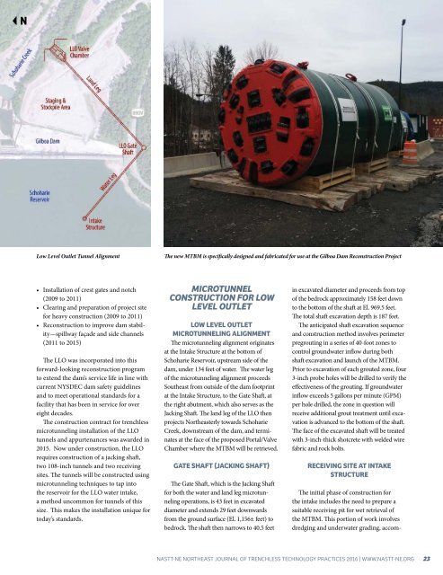
Low Level Outlet Tunnel Alignment<br />
The new MTBM is specifically designed and fabricated for use at the Gilboa Dam Reconstruction Project<br />
• Installation of crest gates and notch<br />
(2009 to 2011)<br />
• Clearing and preparation of project site<br />
for heavy construction (2009 to 2011)<br />
• Reconstruction to improve dam stability—spillway<br />
façade and side channels<br />
(2011 to 2015)<br />
The LLO was incorporated into this<br />
forward-looking reconstruction program<br />
to extend the dam’s service life in line with<br />
current NYSDEC dam safety guidelines<br />
and to meet operational standards for a<br />
facility that has been in service for over<br />
eight decades.<br />
The construction contract for trenchless<br />
microtunneling installation of the LLO<br />
tunnels and appurtenances was awarded in<br />
2015. Now under construction, the LLO<br />
requires construction of a jacking shaft,<br />
two 108-inch tunnels and two receiving<br />
sites. The tunnels will be constructed using<br />
microtunneling techniques to tap into<br />
the reservoir for the LLO water intake,<br />
a method uncommon for tunnels of this<br />
size. This makes the installation unique for<br />
today’s standards.<br />
MICROTUNNEL<br />
CONSTRUCTION FOR LOW<br />
LEVEL OUTLET<br />
LOW LEVEL OUTLET<br />
MICROTUNNELING ALIGNMENT<br />
The microtunneling alignment originates<br />
at the Intake Structure at the bottom of<br />
Schoharie Reservoir, upstream side of the<br />
dam, under 134 feet of water. The water leg<br />
of the microtunneling alignment proceeds<br />
Southeast from outside of the dam footprint<br />
at the Intake Structure, to the Gate Shaft, at<br />
the right abutment, which also serves as the<br />
Jacking Shaft. The land leg of the LLO then<br />
projects Northeasterly towards Schoharie<br />
Creek, downstream of the dam, and terminates<br />
at the face of the proposed Portal/Valve<br />
Chamber where the MTBM will be retrieved.<br />
GATE SHAFT (JACKING SHAFT)<br />
The Gate Shaft, which is the Jacking Shaft<br />
for both the water and land leg microtunneling<br />
operations, is 43 feet in excavated<br />
diameter and extends 29 feet downwards<br />
from the ground surface (El. 1,156± feet) to<br />
bedrock. The shaft then narrows to 40.5 feet<br />
in excavated diameter and proceeds from top<br />
of the bedrock approximately 158 feet down<br />
to the bottom of the shaft at El. 969.5 feet.<br />
The total shaft excavation depth is 187 feet.<br />
The anticipated shaft excavation sequence<br />
and construction method involves perimeter<br />
pregrouting in a series of 40-foot zones to<br />
control groundwater inflow during both<br />
shaft excavation and launch of the MTBM.<br />
Prior to excavation of each grouted zone, four<br />
3-inch probe holes will be drilled to verify the<br />
effectiveness of the grouting. If groundwater<br />
inflow exceeds 5 gallons per minute (GPM)<br />
per hole drilled, the zone in question will<br />
receive additional grout treatment until excavation<br />
is advanced to the bottom of the shaft.<br />
The face of the excavated shaft will be treated<br />
with 3-inch-thick shotcrete with welded wire<br />
fabric and rock bolts.<br />
RECEIVING SITE AT INTAKE<br />
STRUCTURE<br />
The initial phase of construction for<br />
the intake includes the need to prepare a<br />
suitable receiving pit for wet retrieval of<br />
the MTBM. This portion of work involves<br />
dredging and underwater grading, accom-<br />
NASTT-NE NORTHEAST JOURNAL OF TRENCHLESS TECHNOLOGY <strong>PRACTICES</strong> 2016 | WWW.NASTT-NE.ORG 23