

PRACTICES
nastt-ne-journal-2016
nastt-ne-journal-2016

Create successful ePaper yourself
Turn your PDF publications into a flip-book with our unique Google optimized e-Paper software.
HORIZONTAL<br />
FEET<br />
VERTICAL<br />
FEET<br />
After the land leg tunnel construction is<br />
complete, the contractor will continue with<br />
other work necessary for installation of the<br />
valve chamber structure, connection with<br />
the tunnel, and finishing for LLO mechanical<br />
work within the gate shaft to control the<br />
water release into Schoharie Creek.<br />
MICROTUNNELING CONSTRUCTION<br />
FOR LOW LEVEL OUTLET TUNNELS<br />
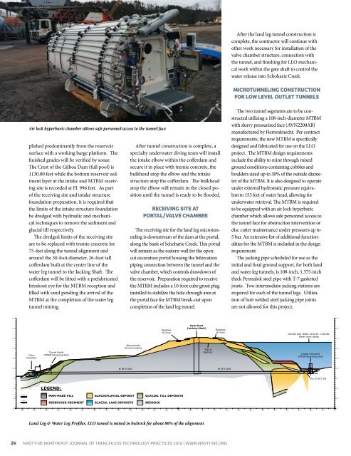
Air lock hyperbaric chamber allows safe personnel access to the tunnel face<br />
plished predominantly from the reservoir<br />
surface with a working barge platform. The<br />
finished grades will be verified by sonar.<br />
The Crest of the Gilboa Dam (full pool) is<br />
1130.00 feet while the bottom reservoir sediment<br />
layer at the intake and MTBM receiving<br />
site is recorded at El. 996 feet. As part<br />
of the receiving site and intake structure<br />
foundation preparation, it is required that<br />
the limits of the intake structure foundation<br />
be dredged with hydraulic and mechanical<br />
techniques to remove the sediment and<br />
glacial till respectively.<br />
The dredged limits of the receiving site<br />
are to be replaced with tremie concrete for<br />
75-feet along the tunnel alignment and<br />
around the 30-foot diameter, 26-foot tall<br />
cofferdam built at the center line of the<br />
water leg tunnel to the Jacking Shaft. The<br />
cofferdam will be fitted with a prefabricated<br />
breakout eye for the MTBM reception and<br />
filled with sand pending the arrival of the<br />
MTBM at the completion of the water leg<br />
tunnel mining.<br />
After tunnel construction is complete, a<br />
specialty underwater diving team will install<br />
the intake elbow within the cofferdam and<br />
secure it in place with tremie concrete, the<br />
bulkhead atop the elbow and the intake<br />
structure atop the cofferdam. The bulkhead<br />
atop the elbow will remain in the closed position<br />
until the tunnel is ready to be flooded.<br />
RECEIVING SITE AT<br />
PORTAL/VALVE CHAMBER<br />
The receiving site for the land leg microtunneling<br />
is downstream of the dam at the portal,<br />
along the bank of Schoharie Creek. This portal<br />
will remain as the eastern wall for the opencut<br />
excavation portal housing the bifurcation<br />
piping connection between the tunnel and the<br />
valve chamber, which controls drawdown of<br />
the reservoir. Preparation required to receive<br />
the MTBM includes a 10-foot cube grout plug<br />
installed to stabilize the hole-through area at<br />
the portal face for MTBM break-out upon<br />
completion of the land leg tunnel.<br />
The two tunnel segments are to be constructed<br />
utilizing a 108-inch-diameter MTBM<br />
with slurry pressurized face (AVN2200AB)<br />
manufactured by Herrenknecht. Per contract<br />
requirements, the new MTBM is specifically<br />
designed and fabricated for use on the LLO<br />
project. The MTBM design requirements<br />
include the ability to mine through mixed<br />
ground conditions containing cobbles and<br />
boulders sized up to 30% of the outside diameter<br />
of the MTBM. It is also designed to operate<br />
under external hydrostatic pressure equivalent<br />
to 153 feet of water head, allowing for<br />
underwater retrieval. The MTBM is required<br />
to be equipped with an air lock hyperbaric<br />
chamber which allows safe personnel access to<br />
the tunnel face for obstruction intervention or<br />
disc cutter maintenance under pressures up to<br />
5 bar. An extensive list of additional functionalities<br />
for the MTBM is included in the design<br />
requirement.<br />
The jacking pipe scheduled for use as the<br />
initial and final ground support, for both land<br />
and water leg tunnels, is 108-inch, 1.375-inch<br />
thick Permalok steel pipe with T-7 gasketed<br />
joints. Two intermediate jacking stations are<br />
required for each of the tunnel legs. Utilization<br />
of butt welded steel jacking pipe joints<br />
are not allowed for this project.<br />
1250<br />
1250<br />
1200<br />
1150<br />
Roadway<br />
& Drive<br />
Gate Shaft<br />
(Jacking Shaft)<br />
Roadway<br />
& Drive<br />
Normal Pool Water Level El. 1130.00.<br />
Water level varies<br />
1200<br />
1150<br />
1100<br />
1050<br />
Valve<br />
Chamber<br />
Tunnel Portal<br />
(MTBM Receiving Site)<br />
Approximate<br />
Ground Surface<br />
Top of<br />
Bedrock<br />
Intake Structure<br />
(MTBM Receiving Site)<br />
1100<br />
1050<br />
1000<br />
NE FLOW<br />
SE FLOW<br />
~<br />
1000<br />
950<br />
Inv. El 977.00<br />
950<br />
900<br />
LEGEND:<br />
900<br />
850<br />
MAN-MADE FILL<br />
GLACIOFLUVIAL DEPOSIT<br />
GLACIAL TILL DEPOSITS<br />
850<br />
RESERVOIR SEDIMENT<br />
GLACIAL LAKE DEPOSITS<br />
BEDROCK<br />
800<br />
800<br />
24+00<br />
23+00 22+00<br />
21+00 20+00 19+00 18+00 17+00 16+00 15+00 14+00 13+00 12+00<br />
11+00<br />
10+00 9+00 8+00 7+00 6+00 5+00 4+00 3+00 2+00 1+00 0+00<br />
-1+00<br />
-2+00<br />
Land Leg & Water Leg Profiles. LLO tunnel is mined in bedrock for about 80% of the alignment<br />
24 NASTT-NE NORTHEAST JOURNAL OF TRENCHLESS TECHNOLOGY <strong>PRACTICES</strong> 2016 | WWW.NASTT-NE.ORG