

EC6201_uw

You also want an ePaper? Increase the reach of your titles
YUMPU automatically turns print PDFs into web optimized ePapers that Google loves.
This ranges from 0.1 to 10µ mhos.<br />
III.<br />
Forward current gain (h fb ): It is defined as the ratio of change in output current (collector<br />
current) to change in input current (emitter current) with the output voltage (collector<br />
voltage) is kept constant.<br />
This ranges from 0.9 to 1.0.<br />
IV.<br />
Reverse voltage gain (h rb ): It is defined as the ratio of change in input voltage (emitter<br />
voltage) to change in output voltage (collector voltage) with the input current (emitter<br />
current) is kept constant.<br />
This ranges from 10 -5 to 10 -4 .<br />
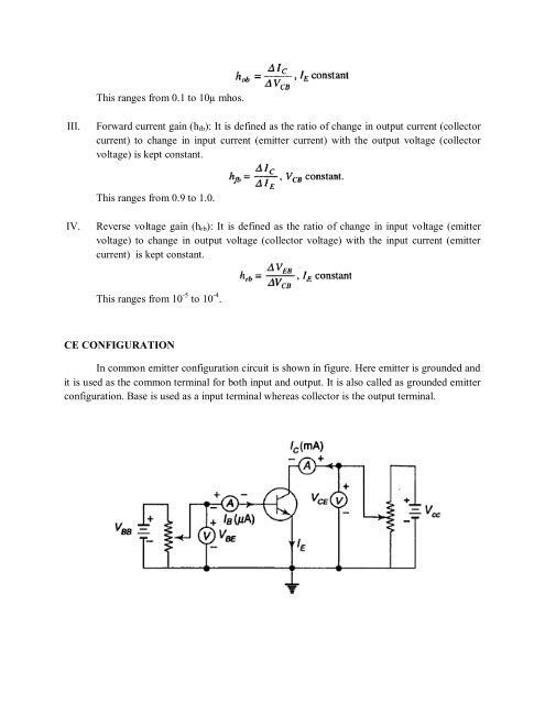
CE CONFIGURATION<br />
In common emitter configuration circuit is shown in figure. Here emitter is grounded and<br />
it is used as the common terminal for both input and output. It is also called as grounded emitter<br />
configuration. Base is used as a input terminal whereas collector is the output terminal.