- Page 2:
Computer Testing Supplement for Ins
- Page 6 and 7:
Table of Contents Preface .........
- Page 8 and 9:
• A7S0, Piper PA-34-200 • A11EA
- Page 10 and 11:
Section I: Title 14 of the Code of
- Page 12 and 13:
§ 1.1 General definitions. PART 1
- Page 14 and 15:
Category B, with respect to transpo
- Page 16 and 17:
(1) An ETOPS group 1 Significant Sy
- Page 18 and 19:
Glider means a heavier-than-air air
- Page 20 and 21:
Long-range communication system (LR
- Page 22 and 23:
Overseas air transportation means t
- Page 24 and 25:
Rated maximum continuous augmented
- Page 26 and 27:
(2) With respect to turbine engines
- Page 28 and 29:
ETOPS means extended operations. EW
- Page 30 and 31:
SSALS means simplified short approa
- Page 32 and 33:
(2) May is used in a permissive sen
- Page 34 and 35:
§ 23.1 Applicability. PART 23—AI
- Page 36 and 37:
(i) The highest weight selected by
- Page 38 and 39:
[Doc. No. 4080, 29 FR 17955, Dec. 1
- Page 40 and 41:
significantly reduce the capability
- Page 42 and 43:
(1) The instrument that most effect
- Page 44 and 45:
[Amdt. 23-1, 30 FR 8261, June 29, 1
- Page 46 and 47:
(2) Each exposed sight gauge used a
- Page 48 and 49:
[Doc. No. 4080, 29 FR 17955, Dec. 1
- Page 50 and 51:
(c) Main power cables (including ge
- Page 52 and 53:
(c) Rear position light installatio
- Page 54 and 55:
system is observed from a distance,
- Page 56 and 57:
(c) For those airplanes required to
- Page 58 and 59:
(d) As used in this section: (1) BT
- Page 60 and 61:
§23.1457 Cockpit voice recorders.
- Page 62 and 63:
23.1511 Flap extended speed. (a) Th
- Page 64 and 65:
23.1541 General. (a) The airplane m
- Page 66 and 67:
(1) Each fuel tank selector control
- Page 68 and 69:
(2) Stating that recovery must be i
- Page 70 and 71:
(3) Acrobatic category airplanes. A
- Page 72 and 73:
(4) The effect on landing distances
- Page 74 and 75:
ecommended at these periods. Howeve
- Page 76 and 77:
Subpart A—General §27.1 Applicab
- Page 78 and 79:
(3) The portion of the total weight
- Page 80 and 81:
warn the pilot of the occurrence of
- Page 82 and 83:
(c) Except as provided in paragraph
- Page 84 and 85:
(2) Compliance with paragraph (a)(1
- Page 86 and 87:
§27.1365 Electric cables. (a) Each
- Page 88 and 89:
§27.1391 Minimum intensities in th
- Page 90 and 91:
where: Ie=effective intensity (cand
- Page 92 and 93:
(2) By installing a continually ene
- Page 94 and 95:
§27.1505 Never-exceed speed. (a) T
- Page 96 and 97:
(i) The maximum value determined by
- Page 98 and 99:
(b) Each arc and line must be wide
- Page 100 and 101:
(2) Oil filler openings must be mar
- Page 102 and 103:
(ii) The maximum safe wind for oper
- Page 104 and 105:
PART 39—AIRWORTHINESS DIRECTIVES
- Page 106 and 107:
PART 43—MAINTENANCE, PREVENTIVE M
- Page 108 and 109:
§ 43.5 Approval for return to serv
- Page 110 and 111:
is permanently removed from use on
- Page 112 and 113:
(b) Rotorcraft. Each person perform
- Page 114 and 115:
Appendix A to Part 43—Major Alter
- Page 116 and 117:
(2) Powerplant major repairs. Repai
- Page 118 and 119:
(31) Removing and replacing self-co
- Page 120 and 121:
(3) Internal engine—for cylinder
- Page 122 and 123:
(vi) Barometric scale error. At con
- Page 124 and 125:
Appendix F to Part 43—ATC Transpo
- Page 126 and 127:
§ 45.1 Applicability. This part pr
- Page 128 and 129:
§ 45.14 Identification of critical
- Page 130 and 131:
§ 45.25 Location of marks on fixed
- Page 132 and 133:
§ 91.1 Applicability. PART 91—GE
- Page 134 and 135:
hospital, or doctor, or other perso
- Page 136 and 137:
§§ 91.27-91.99 [Reserved] § 91.2
- Page 138 and 139:
(i) Airplanes with a third attitude
- Page 140 and 141:
(11) On and after January 1, 2004,
- Page 142 and 143:
(iv) Required to be operational by
- Page 144 and 145:
(5) Accept necessary barometric pre
- Page 146 and 147:
§ 91.407 Operation after maintenan
- Page 148 and 149:
(g) Inspection program approved und
- Page 150 and 151:
(iii) The time since last overhaul
- Page 152 and 153:
Section II: Airworthiness Directive
- Page 154 and 155:
MESSERSCHMITT-BOLKOW-BLOHM-GMBH AND
- Page 156 and 157:
AGUSTA, COSTRUZIONI AERONAUTICHE GI
- Page 158 and 159:
BEECH =============================
- Page 160 and 161:
d. Coat entire portion of bolt that
- Page 162 and 163:
AIR TRACTOR, INC. =================
- Page 164 and 165:
BENDIX ============================
- Page 166 and 167:
ENSTROM ===========================
- Page 168 and 169:
BEECH =============================
- Page 170 and 171: BEECH AIRCRAFT CORPORATION ========
- Page 172 and 173: PRATT & WITHEY AIRCRAFT OF CANADA,
- Page 174 and 175: (j) Install a CT stator assembly, a
- Page 176 and 177: Section III: Exhibits • Exhibit 1
- Page 178 and 179: Rivet identifi cation and part numb
- Page 180 and 181: Aircraft rivet identification. EXHI
- Page 182 and 183: Aircraft rivet identification. (con
- Page 184 and 185: Thickness “t” in inches No. of
- Page 186 and 187: Thickness “t” in inches No. of
- Page 188 and 189: Thickness “t” in inches No. of
- Page 190 and 191: Recommended radii for 90° bends in
- Page 192 and 193: Minimum Bend Radius for Aluminum Al
- Page 194 and 195: 3-19 RADIUS THICKNESS 1/32 .031 1/1
- Page 196 and 197: EXHIBIT 10 K-chart for determining
- Page 198 and 199: . . DATUM D C.G. L . . NOSE WHEEL T
- Page 200 and 201: COMPUTED WEIGHING POINT (C MAIN WHE
- Page 202 and 203: NOSE SCALE 464 LBS. TARE 10 LBS. We
- Page 204 and 205: FULL OIL EXHIBIT 14 Example of chec
- Page 206 and 207: FULL OIL EXHIBIT 15 Example of chec
- Page 208 and 209: 1. GENERAL. The minimum airworthine
- Page 210 and 211: Utility Category Aircraft (FAR 23)
- Page 212 and 213: EXHIBIT 17 Turnbuckle safetying gui
- Page 214 and 215: Straight-shank terminal dimensions
- Page 216 and 217: BEND RADIUS INCHES 3 — 2 — 1
- Page 218 and 219: MINIMUM BEND RADIUS (INCHES) 16 15
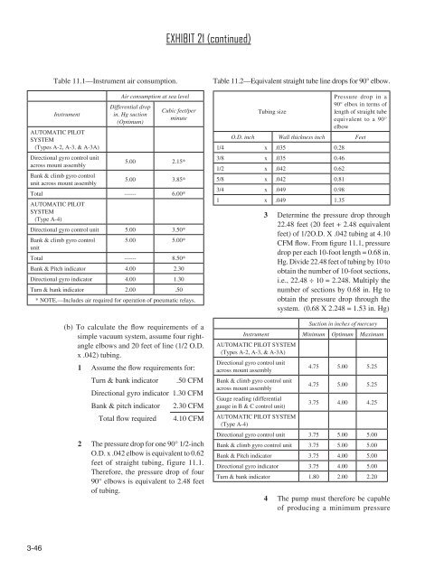
- Page 222 and 223: differential of 5.53 in. Hg, i.e.,
- Page 224 and 225: DC wire and circuit protector chart
- Page 226 and 227: Where: T1 T2 TR I2 Imax TABLE 11-9.
- Page 228 and 229: 11-67. METHODS FOR DETERMINING CURR
- Page 230 and 231: (1) The wire run is 15.5 feet long,
- Page 232 and 233: STEP 1: Refer to the “single wire
- Page 234 and 235: FIGURE 11-3. Conductor chart, inter
- Page 236 and 237: FIGURE 11-4b. Single copper wire in
- Page 238 and 239: FIGURE 11-6. Altitude derating curv
- Page 240 and 241: Minimum Equipment List Page MINIMUM
- Page 242 and 243: EXHIBIT 24 Bend Allowance = 2π (R
- Page 244 and 245: EXHIBIT 25 c = 2π a 2 + b 2 2 Circ
- Page 246 and 247: Section IV: Type Certificate Data S
- Page 248 and 249: TCDS BACKGROUND INFORMATION Type Ce
- Page 250 and 251: Coded Entries Many aircraft and eng
- Page 252 and 253: DEPARTMENT OF TRANSPORTATION FEDERA
- Page 254 and 255: I. Model 208, Caravan (cont’d) 3
- Page 256 and 257: II. - Model 208B, Caravan (cont’d
- Page 258 and 259: Data Pertinent to All Models (cont
- Page 260: Data Pertinent to All Models (cont
- Page 263 and 264: TCDS E4EA PAGE 2 IV. MODEL TYPE (se
- Page 265 and 266: TCDS E4EA PAGE 4 I. MODELS (Cont.))
- Page 267 and 268: TCDS E4EA PAGE 6 I. MODELS (cont.)
- Page 269 and 270: TCDS E4EA PAGE 8 II. MODELS PT6A-45
- Page 271 and 272:
TCDS E4EA PAGE 10 III. MODELS (cont
- Page 273 and 274:
TCDS E4EA PAGE 12 PT6A-28 PT6A-29 P
- Page 275 and 276:
TCDS E4EA PAGE 14 NOTE 1.(continued
- Page 277 and 278:
TCDS E4EA PAGE 16 Maximum Continuou
- Page 279 and 280:
TCDS E4EA PAGE 18 Accessory Drive P
- Page 281 and 282:
TCDS E4EA PAGE 20 NOTE 7. The maxim
- Page 283 and 284:
TCDS E4EA PAGE 22 NOTE 13. (Cont'd)
- Page 285 and 286:
P9NE 2 NOTE 2. Blade Model Designat
- Page 287 and 288:
P60GL Page 2 of 3 Certification Bas
- Page 290 and 291:
Page No. 1 2 3 Rev. No. 29 29 29 Re
- Page 292:
E-252 Page 3 The Model 0-200-C is s
- Page 295 and 296:
2A13 Page 2 of 43 Center of Gravity
- Page 297 and 298:
2A13 Page 4 of 43 Propeller Spinner
- Page 299 and 300:
2A13 Page 6 of 43 Propeller Spinner
- Page 301 and 302:
2A13 Page 8 of 43 VI - Model PA-28-
- Page 303 and 304:
2A13 Page 10 of 43 Center of Gravit
- Page 305 and 306:
2A13 Page 12 of 43 Empty Weight C.
- Page 307 and 308:
2A13 Page 14 of 43 X - Model PA-28R
- Page 309 and 310:
2A13 Page 16 of 43 Control Surface
- Page 311 and 312:
2A13 Page 18 of 43 Engine Limits Fo
- Page 313 and 314:
2A13 Page 20 of 43 Manufacturer's S
- Page 315 and 316:
2A13 Page 22 of 43 Center of Gravit
- Page 317 and 318:
2A13 Page 24 of 43 XVI - B. Model P
- Page 319 and 320:
2A13 Page 26 of 43 No. of Seats Nor
- Page 321 and 322:
2A13 Page 28 of 43 Airspeed Limits
- Page 323 and 324:
2A13 Page 30 of 43 Propeller and Pr
- Page 325 and 326:
2A13 Page 32 of 43 Engine Limits Fo
- Page 327 and 328:
2A13 Page 34 of 43 Manufacturer's S
- Page 329 and 330:
2A13 Page 36 of 43 PA-28-236: CAR 3
- Page 331 and 332:
2A13 Page 38 of 43 (Continued) MODE
- Page 333 and 334:
2A13 Page 40 of 43 NOTE 3 The Model
- Page 335 and 336:
2A13 Page 42 of 43 NOTE 20 PA-28-18
- Page 338 and 339:
DEPARTMENT OF TRANSPORTATION FEDERA
- Page 340 and 341:
II - Model 150D, Model 150E, Model
- Page 342 and 343:
IV - Model A150K, Aerobat, 2 PCLM (
- Page 344 and 345:
V - Model 150L (cont’d) Page 7 of
- Page 346 and 347:
VII - Model 150M (cont’d) Page 9
- Page 348 and 349:
IX - Model 152 (cont'd) Page 11 of
- Page 350 and 351:
X - Model A152 (cont’d) Page 13 o
- Page 352 and 353:
Data Pertinent to All Models (cont
- Page 354 and 355:
Page 17 of 19 3A19 Data Pertinent t
- Page 356:
Data Pertinent to All Models (cont
- Page 359 and 360:
E-295 Page 2 of 8 Model Lycoming O-
- Page 361 and 362:
E-295 Page 4 of 8 Certification bas
- Page 363 and 364:
E-295 Page 6 of 8 NOTE 5. These mod
- Page 365 and 366:
E-295 Page 8 of 8 NOTE 12. When equ
- Page 367 and 368:
A7CE Page 2 of 24 Propeller and or
- Page 369 and 370:
A7CE Page 4 of 24 II - Model 401, M
- Page 371 and 372:
A7CE Page 6 of 24 III - Model 402,
- Page 373 and 374:
A7CE Page 8 of 24 IV - Model 421, M
- Page 375 and 376:
A7CE Page 10 of 24 V - Model 414 (N
- Page 377 and 378:
A7CE Page 12 of 24 VI - Model 421B
- Page 379 and 380:
A7CE Page 14 of 24 VII - Model 421C
- Page 381 and 382:
A7CE Page 16 of 24 VIII - Model 414
- Page 383 and 384:
A7CE Page 18 of 24 IX - Model 402C
- Page 385 and 386:
A7CE Page 20 of 24 X - Model 425 (c
- Page 387 and 388:
A7CE Page 22 of 24 X - Model 425 (c
- Page 389 and 390:
A7CE Page 24 of 24 NOTE 3. (cont'd.
- Page 391 and 392:
3A13 Page 2 of 37 Rev. 66 I - Model
- Page 393 and 394:
3A13 Page 4 of 37 Rev. 66 II - Mode
- Page 395 and 396:
3A13 Page 6 of 37 Rev. 66 IV - Mode
- Page 397 and 398:
3A13 Page 8 of 37 Rev. 66 V - Model
- Page 399 and 400:
3A13 Page 10 of 37 Rev. 66 VII - Mo
- Page 401 and 402:
3A13 Page 12 of 37 Rev. 66 VIII - M
- Page 403 and 404:
3A13 Page 14 of 37 Rev. 66 X - Mode
- Page 405 and 406:
3A13 Page 16 of 37 Rev. 66 Model TR
- Page 407 and 408:
3A13 Page 18 of 37 Rev. 66 Model 18
- Page 409 and 410:
3A13 Page 20 of 37 Rev. 66 Data Per
- Page 411 and 412:
3A13 Page 22 of 37 Rev. 66 Data Per
- Page 413 and 414:
3A13 Page 24 of 37 Rev. 66 Data Per
- Page 415 and 416:
3A13 Page 26 of 37 Rev. 66 Long ran
- Page 417 and 418:
3A13 Page 28 of 37 Rev. 66 (3) On t
- Page 419 and 420:
3A13 Page 30 of 37 Rev. 66 Data Per
- Page 421 and 422:
3A13 Page 32 of 37 Rev. 66 XIII - M
- Page 423 and 424:
3A13 Page 34 of 37 Rev. 66 Special
- Page 425 and 426:
3A13 Page 36 of 37 Rev. 66 Oil Capa
- Page 428 and 429:
DEPARTMENT OF TRANSPORTATION FEDERA
- Page 430 and 431:
Maximum Weight S/N 34-7250215 throu
- Page 432 and 433:
5 of 16 A7SO Maximum Weight 4570 lb
- Page 434 and 435:
Maximum Weight 4773 lb. - Ramp 4750
- Page 436 and 437:
Oil Capacity 8 qts. per engine (5 q
- Page 438 and 439:
11 of 16 A7SO Control Surface Movem
- Page 440 and 441:
13 of 16 A7SO Equipment The basic r
- Page 442 and 443:
15 of 16 A7SO The Model PA-34-200T;
- Page 444 and 445:
Page No. 1 2 3 4 5 6 7 8 Rev. No. 1
- Page 446 and 447:
Page 3 A11EA 3. McCauley Model 1A10
- Page 448 and 449:
Oil capacity 6 qt. at (+39) (2 qt.
- Page 450 and 451:
UTILITY CATEGORY AA-1 AA-1A Maximum
- Page 452 and 453:
DEPARTMENT OF TRANSPORTATION FEDERA
- Page 454 and 455:
Page 3 of 15 1A6 Maximum Baggage50
- Page 456 and 457:
Page 5 of 15 1A6 Fuel Capacity 36 g
- Page 458 and 459:
Page 7 of 15 1A6 Fuel Capacity 36 g
- Page 460 and 461:
Page 9 of 15 1A6 Required Equipment
- Page 462 and 463:
Page 11 of 15 1A6 105. Vacuum pump
- Page 464 and 465:
Page 13 of 15 1A6 (w) FAA-DOA appro
- Page 466:
Page 15 of 15 1A6 (3) On left side
- Page 469 and 470:
E-273 Page 2 Model O-470-A O-470-E
- Page 471 and 472:
E-273 Page 4 NOTE 3. The following
- Page 473 and 474:
E-273 Page 6 NOTE 13. The following
- Page 475 and 476:
P57GL Page 2 of 5 Maximum Diameter
- Page 477 and 478:
P57GL Page 4 of 5 NOTE 3. Pitch Con
- Page 480 and 481:
DEPARTMENT OF TRANSPORTATION P-920
- Page 482 and 483:
Page 3 of 12 P-920, Revision 29 Max
- Page 484 and 485:
Note 2: Blade Model Designation (Se
- Page 486 and 487:
Note 9: Special Limits Page 7 of 12
- Page 488 and 489:
Page 9 of 12 P-920, Revision 29 Hub
- Page 490 and 491:
Page 11 of 12 P-920, Revision 29 Hu
- Page 492 and 493:
DEPARTMENT OF TRANSPORTATION FEDERA
- Page 494 and 495:
3 2A4 II. - Model 680-E (cont’d)
- Page 496 and 497:
5 2A4 III. - Model 720 (cont’d) L
- Page 498 and 499:
V - Model 560-F, 7 PCLM (Normal Cat
- Page 500 and 501:
9 2A4 VI - Model 680-FL (cont’d)
- Page 502 and 503:
11 2A4 VII - MODEL 680-FL(P) (cont
- Page 504 and 505:
13 2A4 IX - MODEL 680-V, 11 PCLM (N
- Page 506 and 507:
15 2A4 X - MODEL 680-W (cont’d) D
- Page 508 and 509:
17 2A4 XI - MODEL 681 (cont’d) Se
- Page 510 and 511:
19 2A4 XIII - MODEL 685 (cont’d)
- Page 512 and 513:
XIV - MODEL 690A (cont’d) Maximum
- Page 514 and 515:
23 2A4 XVI - MODEL 690C, 11 PCLM (N
- Page 516 and 517:
25 2A4 XVII - MODEL 695 (cont’d)
- Page 518 and 519:
27 2A4 XVIII - MODEL 695A (cont’d
- Page 520 and 521:
29 2A4 XIX - MODEL 690D (cont’d)
- Page 522 and 523:
31 2A4 Specifications Pertinent to
- Page 524 and 525:
33 2A4 NOTE 6: Model 680FL S/N 1471
- Page 526 and 527:
Page No. 1 2 3 4 Rev. No. 9 9 9 9 R
- Page 528 and 529:
3 E-284 NOTE 4. The "6" in the engi
- Page 530 and 531:
DEPARTMENT OF TRANSPORTATION FEDERA
- Page 532 and 533:
Page 3 of 17 A9CE II. Model A188, A
- Page 534 and 535:
III. Model 188A, AGwagon "A" & "B"
- Page 536 and 537:
V. Model 188B, AGpickup (cont'd) *E
- Page 538 and 539:
Page 9 of 17 A9CE VI. Model A188B (
- Page 540 and 541:
VII. Model T188C (cont'd) Number of
- Page 542 and 543:
Page 13 of 17 A9CE Reference weight
- Page 544 and 545:
Page 15 of 17 A9CE Fuel Flows at Fu
- Page 546:
NOTE 8. 14 volt electrical system 1
- Page 549 and 550:
3A12 2 Rev. 77 I. Model 172 (cont'd
- Page 551 and 552:
3A12 4 Rev. 77 II. Model 172A, Mode
- Page 553 and 554:
3A12 6 Rev. 77 IV. Model 172D, Mode
- Page 555 and 556:
3A12 8 Rev. 77 V. Model 172I, Model
- Page 557 and 558:
3A12 10 Rev. 77 VI. Model 172L (con
- Page 559 and 560:
3A12 12 Rev. 77 VIII. Model 172N (c
- Page 561 and 562:
3A12 14 Rev. 77 IX. Model 172P (con
- Page 563 and 564:
3A12 16 Rev. 77 DATA PERTINENT TO A
- Page 565 and 566:
3A12 18 Rev. 77 DATA PERTINENT TO A
- Page 567 and 568:
3A12 20 Rev. 77 DATA PERTINENT TO A
- Page 569 and 570:
3A12 22 Rev. 77 DATA PERTINENT TO A
- Page 571 and 572:
3A12 24 Rev. 77 DATA PERTINENT TO A
- Page 573 and 574:
3A12 26 Rev. 77 XI - Model 172R (co
- Page 575 and 576:
3A12 28 Rev. 77 Data Pertinent to M
- Page 577 and 578:
3A12 30 Rev. 77 XII - Model 172S (c
- Page 580 and 581:
DEPARTMENT OF TRANSPORTATION FEDERA
- Page 582 and 583:
3 A16CE Control Surface Movements W
- Page 584 and 585:
5 A16CE Data Pertinent to All Model
- Page 586 and 587:
7 A16CE (6) On cargo door: "Baggage
- Page 588 and 589:
9 A16CE (7) Near the manifold press
- Page 590:
11 A16CE NOTE 5. The marking of the
- Page 593 and 594:
Page 2 of 43 3A21 I - Model 210 (co
- Page 595 and 596:
Page 4 of 43 3A21 III - Model 210B,
- Page 597 and 598:
V - Model 210D (cont’d) Empty wt.
- Page 599 and 600:
Page 8 of 43 3A21 VII - Model T210F
- Page 601 and 602:
Page 10 of 43 3A21 IX - Model T210G
- Page 603 and 604:
XI - Model T210J (cont’d) Page 12
- Page 605 and 606:
Page 14 of 43 3A21 XIII Model 210K/
- Page 607 and 608:
Page 16 of 43 3A21 XIV - Model 210M
- Page 609 and 610:
Page 18 of 43 3A21 XV - Model P210N
- Page 611 and 612:
Page 20 of 43 3A21 Model 210N (cont
- Page 613 and 614:
XVII - Model P210R (cont’d) Fuel
- Page 615 and 616:
Model T210R (cont’d) Fuel Capacit
- Page 617 and 618:
Page 26 of 43 3A21 NOTE 2. (cont’
- Page 619 and 620:
Page 28 of 43 3A21 NOTE 2. (4) On f
- Page 621 and 622:
Page 30 of 43 3A21 NOTE 2. (cont’
- Page 623 and 624:
Page 32 of 43 3A21 NOTE 2. (cont’
- Page 625 and 626:
Page 34 of 43 3A21 NOTE 2. (cont’
- Page 627 and 628:
NOTE 2. (cont’d) J. (10) Page 36
- Page 629 and 630:
NOTE 2. (cont’d) J. (21) Near the
- Page 631 and 632:
Page 40 of 43 3A21 NOTE 2. (cont’
- Page 633 and 634:
Page 42 of 43 3A21 NOTE 2. K. (26)
- Page 636 and 637:
DEPARTMENT OF TRANSPORTATION FEDERA
- Page 638 and 639:
A3SO Page 3 of 31 I. - Model PA-32-
- Page 640 and 641:
A3SO Page 5 of 31 II. - Model PA-32
- Page 642 and 643:
A3SO Page 7 of 31 III. - Model PA-3
- Page 644 and 645:
A3SO Page 9 of 31 V. - Model PA-32R
- Page 646 and 647:
A3SO Page 11 of 31 VI. - Model PA-3
- Page 648 and 649:
A3SO Page 13 of 31 VII. - Model PA-
- Page 650 and 651:
A3SO Page 15 of 31 IX. - Model PA-3
- Page 652 and 653:
A3SO Page 17 of 31 X. - Model PA-32
- Page 654 and 655:
A3SO Page 19 of 31 XI. - Model PA-3
- Page 656 and 657:
A3SO Page 21 of 31 XII. - Model PA-
- Page 658 and 659:
A3SO Page 23 of 31 XIV. - Model PA-
- Page 660 and 661:
A3SO Page 25 of 31 PA-32R-301, S/N
- Page 662 and 663:
A3SO Page 27 of 31 23.1329, 23.1351
- Page 664 and 665:
A3SO Page 29 of 31 AFM Supp. VB-357
- Page 666 and 667:
A3SO Page 31 of 31 32R-8029121, 32R
- Page 668 and 669:
Section V FAA FORMS • FAA Form 33
- Page 670 and 671:
5-3 Form Approved Electronic Tracki
- Page 672 and 673:
Paperwork Reduction Act Statement:
- Page 674 and 675:
END OF SECTION 5 5-7


