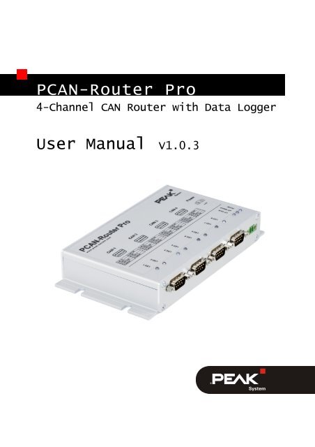
PCAN-Router Pro - User Manual - PEAK-System
PCAN-Router Pro - User Manual - PEAK-System
PCAN-Router Pro - User Manual - PEAK-System

You also want an ePaper? Increase the reach of your titles
YUMPU automatically turns print PDFs into web optimized ePapers that Google loves.
<strong>PCAN</strong>-<strong>Router</strong> <strong>Pro</strong><br />
4-Channel CAN <strong>Router</strong> with Data Logger<br />
<strong>User</strong> <strong>Manual</strong> V1.0.3
<strong>PCAN</strong>-<strong>Router</strong> <strong>Pro</strong> – <strong>User</strong> <strong>Manual</strong><br />
<strong>Pro</strong>ducts taken into account<br />
<strong>Pro</strong>duct Name Model Part number<br />
<strong>PCAN</strong>-<strong>Router</strong> <strong>Pro</strong> 4 High-speed CAN channels,<br />
Wake-up ready; other CAN<br />
transceiver modules on request<br />
IPEH-002212<br />
<strong>Pro</strong>duct names mentioned in this document may be the trademarks or registered<br />
trademarks of their respective companies. They are not explicitly marked by “” and<br />
“®”.<br />
© 2011 <strong>PEAK</strong>-<strong>System</strong> Technik GmbH<br />
<strong>PEAK</strong>-<strong>System</strong> Technik GmbH<br />
Otto-Roehm-Strasse 69<br />
64293 Darmstadt<br />
Germany<br />
Phone: +49 (0)6151 8173-20<br />
Fax: +49 (0)6151 8173-29<br />
www.peak-system.com<br />
info@peak-system.com<br />
Document version 1.0.3 (2011-12-12)<br />
2
<strong>PCAN</strong>-<strong>Router</strong> <strong>Pro</strong> – <strong>User</strong> <strong>Manual</strong><br />
Contents<br />
1 Introduction 5<br />
1.1 <strong>Pro</strong>perties at a Glance 5<br />
1.2 Prerequisites for Operation 6<br />
1.3 Scope of Supply 7<br />
2 Connectors 8<br />
2.1 Power (Voltage Supply) 8<br />
2.2 CAN 1 to CAN 4, D-Sub 9-pin 8<br />
2.3 CompactFlash Card 9<br />
3 Hardware Adjustments 10<br />
3.1 Using an Alternative CAN Transceiver Module 11<br />
3.2 Adjusting the Termination for a CAN Bus 12<br />
3.3 Setting the <strong>Router</strong> ID for the Configuration 13<br />
3.4 Replacing the Button Cell for the Real-Time<br />
Clock (RTC) 14<br />
4 Installing Software 16<br />
5 Operation 18<br />
5.1 Activating the <strong>PCAN</strong>-<strong>Router</strong> <strong>Pro</strong> 18<br />
5.2 Default Bit Rates of the CAN Channels 18<br />
5.3 Shipping Configuration 19<br />
5.3.1 Structure of the Status Messages 20<br />
5.4 Setting the Real-Time Clock 22<br />
5.5 Status LEDs 26<br />
5.6 Wake-up 27<br />
5.6.1 Wake-up via CAN 27<br />
5.6.2 Wake-Up Externally by High Level 27<br />
5.6.3 Wake-Up by Real-Time Clock (RTC) 27<br />
3
<strong>PCAN</strong>-<strong>Router</strong> <strong>Pro</strong> – <strong>User</strong> <strong>Manual</strong><br />
5.7 Sleep Mode 28<br />
6 Logging CAN Data onto a CompactFlash Card 29<br />
6.1 Preparing a CompactFlash Card 29<br />
6.2 Preparing a Configuration for Data Logging 30<br />
6.3 Using Logged Data 32<br />
7 Firmware Update 33<br />
8 Technical Specifications 34<br />
Appendix A CE Certificate 36<br />
Appendix B Dimension Drawing 37<br />
Appendix C Contents of a CompactFlash Card 38<br />
Appendix D <strong>Router</strong> Resources 39<br />
4
<strong>PCAN</strong>-<strong>Router</strong> <strong>Pro</strong> – <strong>User</strong> <strong>Manual</strong><br />
1 Introduction<br />
The <strong>PCAN</strong>-<strong>Router</strong> <strong>Pro</strong> links the data traffic from up to four Highspeed<br />
CAN buses. As well as pure forwarding, the CAN data can be<br />
processed, manipulated and, for example, filtered in a number of<br />
different ways. A virtual fifth CAN channel is used for recording data<br />
traffic to a CompactFlash card. The behavior of the <strong>PCAN</strong>-<strong>Router</strong><br />
<strong>Pro</strong> can be freely configured using a Windows program.<br />
1.1 <strong>Pro</strong>perties at a Glance<br />
4 High-speed CAN channels via plug-in transceiver modules<br />
(wake-up capable); optionally available are modules for Lowspeed,<br />
Single-wire, opto-decoupled High-speed, and High-speed<br />
without wake-up function<br />
CAN connection D-Sub 9-pin<br />
Comprehensive configuration with the Windows software<br />
P<strong>PCAN</strong>-Editor 2<br />
Various function blocks for data processing and manipulation<br />
Configurable beeper<br />
Configurable status LEDs<br />
CAN data and error frames recorded to a CompactFlash card<br />
Conversion of logging data to miscellaneous output formats<br />
using Windows software<br />
Wake-up function using a separate input or the CAN bus<br />
Battery-buffered real-time clock (RTC), can also be used for<br />
wake-up<br />
Voltage supply 8 - 30 V, overvoltage and reversed polarity<br />
protection<br />
5
<strong>PCAN</strong>-<strong>Router</strong> <strong>Pro</strong> – <strong>User</strong> <strong>Manual</strong><br />
Aluminum profile casing with mounting flange<br />
Option for mounting on top hat rails<br />
Customized firmware available on request<br />
Extended operating temperature range of -40 to +85 °C (-40 to<br />
+185 °F)<br />
1.2 Prerequisites for Operation<br />
Voltage supply 8 – 30 V DC (e.g. car battery)<br />
For configuring via CAN:<br />
• Computer with CAN interface of the <strong>PCAN</strong> series (e.g.<br />
<strong>PCAN</strong>-USB)<br />
• CAN cabling with correct termination<br />
• Windows 7/Vista/XP (32/64-bit) for the configuration<br />
program<br />
For converting logged CAN data:<br />
• Computer with card reader for CompactFlash cards<br />
• Windows 7/Vista/XP (32/64-bit) for the converter program<br />
• Sufficient space for data on the hard disk (up to 5 times of<br />
the initial file size from the CompactFlash card, e.g.<br />
1 GByte + 4 GByte)<br />
6
<strong>PCAN</strong>-<strong>Router</strong> <strong>Pro</strong> – <strong>User</strong> <strong>Manual</strong><br />
1.3 Scope of Supply<br />
<strong>PCAN</strong>-<strong>Router</strong> <strong>Pro</strong> in an aluminum casing<br />
Mating connector for the power supply<br />
Configuration software P<strong>PCAN</strong>-Editor 2 for Windows 7/Vista/XP<br />
(32/64-bit)<br />
Converter software for Windows 7/Vista/XP (32/64-bit)<br />
Industrial CompactFlash card (min. 1 GByte)<br />
Documentation in PDF format<br />
7
<strong>PCAN</strong>-<strong>Router</strong> <strong>Pro</strong> – <strong>User</strong> <strong>Manual</strong><br />
2 Connectors<br />
2.1 Power (Voltage Supply)<br />
The operation of the <strong>PCAN</strong>-<strong>Router</strong> <strong>Pro</strong> requires a voltage source<br />
with a nominal 12 V direct current voltage, 8 to 30 V are possible.<br />
The input is electronically protected against reverse polarity and<br />
overvoltage.<br />
The connection is done with the supplied mating connector for<br />
fastening cable strands. The polarity is as follows:<br />
Note: After applying the supply voltage, the <strong>PCAN</strong>-<strong>Router</strong> <strong>Pro</strong><br />
needs a wake-up signal in order to start operation. If the router<br />
is equipped with at least one CAN transceiver module with<br />
wake-up functionality (standard), this happens automatically.<br />
See section 5.6 Wake-up on page 27.<br />
2.2 CAN 1 to CAN 4, D-Sub 9-pin<br />
A CAN bus is connected to a 9-pin D-Sub port. The assignment of<br />
the CAN signals is depending on the used CAN transceiver module<br />
(see table below).<br />
The CAN ports CAN 3 and CAN 4 additionally provide an external<br />
wake-up function (see section 5.6.2 on page 27).<br />
8
<strong>PCAN</strong>-<strong>Router</strong> <strong>Pro</strong> – <strong>User</strong> <strong>Manual</strong><br />
Pin assignment of the ports<br />
CAN 1 and CAN 2<br />
Module name Transmission<br />
standard<br />
CAN-HS High-speed CAN<br />
ISO 11898-2<br />
CAN-HS opto High-speed CAN<br />
ISO 11898-2<br />
CAN-HS-1041<br />
(standard)<br />
High-speed CAN<br />
ISO 11898-2<br />
CAN-LS Low-speed CAN<br />
ISO 11898-3<br />
CAN-LS-SW Single-wire CAN<br />
SAE J2411<br />
2.3 CompactFlash Card<br />
9<br />
Pin assignment of the ports<br />
CAN 3 and CAN 4<br />
Special function Used CAN lines<br />
CAN_L, CAN_H<br />
Galvanic isolation up to<br />
300 V for the CAN interface<br />
CAN_L, CAN_H<br />
Wake-up via CAN CAN_L, CAN_H<br />
Wake-up via CAN CAN_L, CAN_H<br />
Wake-up via CAN CAN_SW<br />
To log the CAN data traffic (trace) you can use CompactFlash cards<br />
(CF cards) with a maximum capacity of 2 GByte.<br />
The CF slot is placed on the rear of the <strong>PCAN</strong>-<strong>Router</strong> <strong>Pro</strong>. The CF<br />
card is properly inserted if it flushes with the rear panel.<br />
Note: When you want to insert or eject a CompactFlash card,<br />
the <strong>PCAN</strong>-<strong>Router</strong> <strong>Pro</strong> must be off or in sleep mode (Power LED<br />
off). Else the card is not detected or data gets lost.<br />
About the use of a CF card see chapter 6 Logging CAN Data onto a<br />
CompactFlash Card on page 29.
<strong>PCAN</strong>-<strong>Router</strong> <strong>Pro</strong> – <strong>User</strong> <strong>Manual</strong><br />
3 Hardware Adjustments<br />
You can adjust some hardware settings on the board of the <strong>PCAN</strong>-<br />
<strong>Router</strong> <strong>Pro</strong>:<br />
Using an alternative CAN transceiver module (on request)<br />
Adjusting the termination for a CAN bus<br />
Setting the <strong>Router</strong> ID for the configuration<br />
Replacing the button cell for the real-time clock<br />
The adjustments are described in the following sections.<br />
Do the following to open the casing of the <strong>PCAN</strong>-<strong>Router</strong> <strong>Pro</strong> in<br />
order to access the possibilities for adjustments:<br />
Along the top edge of the casing remove two screws on each the<br />
front and the rear of the <strong>PCAN</strong>-<strong>Router</strong> <strong>Pro</strong>. Afterwards take off the<br />
upper casing part.<br />
Now you can access the elements of the board.<br />
During reassembling later on take care about the light guides in the<br />
casing part.<br />
10
<strong>PCAN</strong>-<strong>Router</strong> <strong>Pro</strong> – <strong>User</strong> <strong>Manual</strong><br />
3.1 Using an Alternative CAN Transceiver<br />
Module<br />
For each of the four CAN connections an alternative CAN transceiver<br />
module can be inserted on request.<br />
Following modules are available:<br />
Module name Transmission<br />
standard<br />
CAN-HS High-speed CAN<br />
ISO 11898-2<br />
CAN-HS opto High-speed CAN<br />
ISO 11898-2<br />
CAN-HS-1041<br />
(standard)<br />
High-speed CAN<br />
ISO 11898-2<br />
CAN-LS Low-speed CAN<br />
ISO 11898-3<br />
CAN-LS-SW Single-wire CAN<br />
SAE J2411<br />
Special<br />
function<br />
11<br />
Used CAN<br />
lines<br />
Standard bit<br />
rate<br />
CAN_L, CAN_H 500 kbit/s<br />
Galvanic CAN_L, CAN_H 500 kbit/s<br />
isolation up to<br />
300 V for the<br />
CAN interface<br />
Wake-up CAN_L, CAN_H 500 kbit/s<br />
Wake-up CAN_L, CAN_H 125 kbit/s<br />
Wake-up CAN_SW 33.3 kbit/s<br />
The <strong>PCAN</strong>-<strong>Router</strong> <strong>Pro</strong> automatically detects the type of the inserted<br />
CAN transceiver module and adjusts the default bit rate for the CAN<br />
channel. The bit rate can be changed by a configuration.
<strong>PCAN</strong>-<strong>Router</strong> <strong>Pro</strong> – <strong>User</strong> <strong>Manual</strong><br />
3.2 Adjusting the Termination for a CAN<br />
Bus<br />
Depending on the used CAN transceiver module you can activate or<br />
change the CAN bus termination for each CAN connection CAN 1 to<br />
CAN 4 with switch blocks S1 to S4. Switches 1 and 2 on a switch<br />
block always must have the same position. By default the switches<br />
are in OFF position (upper position according to the orientation of<br />
the figure).<br />
Positions of the switch blocks for CAN termination;<br />
ON at lower switch position<br />
Type of transceiver<br />
Termination at switch position *<br />
OFF (upper pos., default) ON (lower pos.)<br />
High-speed CAN (ISO 11898-2) none 120 Ω between<br />
CAN_L and CAN_H<br />
Low-speed CAN (ISO 11898-3) 4.7 kΩ for<br />
1.1 kΩ for<br />
CAN_L and CAN_H CAN_L and CAN_H<br />
Single-wire CAN (SAE J2411) 9.1 kΩ for CAN_SW 2.1 kΩ for CAN_SW<br />
* Both switches of a switch block<br />
12
<strong>PCAN</strong>-<strong>Router</strong> <strong>Pro</strong> – <strong>User</strong> <strong>Manual</strong><br />
3.3 Setting the <strong>Router</strong> ID for the<br />
Configuration<br />
The board of the <strong>PCAN</strong>-<strong>Router</strong> <strong>Pro</strong> has a rotary switch with 16<br />
positions to determine the <strong>Router</strong> ID (0 - F hex = 0 - 15).<br />
Position of the rotary switch for the <strong>Router</strong> ID<br />
When the <strong>PCAN</strong>-<strong>Router</strong> <strong>Pro</strong> is started the configuration with the<br />
number from the internal memory is loaded which matches the<br />
specified <strong>Router</strong> ID. In addition, the <strong>Router</strong> ID gives the <strong>PCAN</strong>-<br />
<strong>Router</strong> <strong>Pro</strong> a unique identification during the P<strong>PCAN</strong> communication<br />
(configuration transfer). For the transmission of CAN messages<br />
during normal operation this <strong>Router</strong> ID is not relevant.<br />
Note: The rotary switch position F is reserved for the firmware<br />
update (start of the bootloader) on the <strong>PCAN</strong>-<strong>Router</strong> <strong>Pro</strong> with<br />
serial number 100 and above.<br />
This is how you change the <strong>Router</strong> ID of a <strong>PCAN</strong>-<strong>Router</strong> <strong>Pro</strong>:<br />
1. Change the position of the rotary switch with a small slot<br />
screwdriver.<br />
13
<strong>PCAN</strong>-<strong>Router</strong> <strong>Pro</strong> – <strong>User</strong> <strong>Manual</strong><br />
2. Restart the <strong>PCAN</strong>-<strong>Router</strong> <strong>Pro</strong> by briefly cutting off the power<br />
supply.<br />
After the restart the changed <strong>Router</strong> ID will be active. Before<br />
the restart changes made at the rotary switch will have no<br />
influence on operation.<br />
During operation with a configuration the LED μC Status blinks<br />
green every second. If a configuration for the set <strong>Router</strong> ID does not<br />
exist, the LED blinks twice as fast.<br />
3.4 Replacing the Button Cell for the<br />
Real-Time Clock (RTC)<br />
The real-time clock (RTC) integrated in the <strong>PCAN</strong>-<strong>Router</strong> <strong>Pro</strong> is supplied<br />
by a button cell of the IEC type CR 1620 (3 V), as long as the<br />
device is not active (without voltage supply or in sleep mode).<br />
Position of the button cell for the real-time clock<br />
A new button cell lasts several years. If the internal clock indicates<br />
an unexpected time, take out the button cell and measure its voltage.<br />
This should be around the nominal 3.0 Volts. If the measured<br />
14
<strong>PCAN</strong>-<strong>Router</strong> <strong>Pro</strong> – <strong>User</strong> <strong>Manual</strong><br />
voltage is lower than 2.5 Volts, you should replace the button cell<br />
with a fresh one.<br />
Find more details about recalling and setting the time in sections 5.3<br />
Shipping Configuration on page 19 and 5.4 Setting the Real-Time<br />
Clock on page 22.<br />
15
<strong>PCAN</strong>-<strong>Router</strong> <strong>Pro</strong> – <strong>User</strong> <strong>Manual</strong><br />
4 Installing Software<br />
Create configurations for the operation with the supplied software<br />
P<strong>PCAN</strong>-Editor for Windows. This chapter covers the installation<br />
procedure for the program. Please find information about the<br />
creation of a configuration in the program help of the P<strong>PCAN</strong>-Editor.<br />
This is how to install the P<strong>PCAN</strong>-Editor:<br />
1. Only Windows XP: Make sure that you are logged in as user<br />
with administrator privileges.<br />
When you use the P<strong>PCAN</strong>-Editor later you can also work as<br />
a user with limited rights.<br />
2. Start the setup program from the supplied CD, directory<br />
Tools/P<strong>PCAN</strong>-Edit.<br />
Startup screen of the installation program for the P<strong>PCAN</strong>-Editor<br />
3. Follow the instructions of the setup program until you come<br />
to the step Select Hardware <strong>Pro</strong>files. At this point select the<br />
entry “<strong>PCAN</strong>-<strong>Router</strong> <strong>Pro</strong>” so that the <strong>PCAN</strong>-<strong>Router</strong> <strong>Pro</strong> will<br />
be supported by the P<strong>PCAN</strong>-Editor.<br />
16
<strong>PCAN</strong>-<strong>Router</strong> <strong>Pro</strong> – <strong>User</strong> <strong>Manual</strong><br />
Choice of the hardware profile for the <strong>PCAN</strong>-<strong>Router</strong> <strong>Pro</strong><br />
4. Follow the remaining instructions of the setup program.<br />
You can then launch the P<strong>PCAN</strong>-Editor, create a configuration, and<br />
send it to the <strong>PCAN</strong>-<strong>Router</strong> <strong>Pro</strong>. Find relevant information in the<br />
help of the P<strong>PCAN</strong>-Editor.<br />
Note: The P<strong>PCAN</strong>-Editor uses the CAN ID 7E7h for communication<br />
with the <strong>PCAN</strong>-<strong>Router</strong> <strong>Pro</strong>. Do not use this CAN ID for<br />
communication on CAN channels that are enabled for configuration<br />
(by default all CAN channels; I/O Function Special Out,<br />
I/O Number “Configuration ID 07e7h enable”)<br />
17
<strong>PCAN</strong>-<strong>Router</strong> <strong>Pro</strong> – <strong>User</strong> <strong>Manual</strong><br />
5 Operation<br />
5.1 Activating the <strong>PCAN</strong>-<strong>Router</strong> <strong>Pro</strong><br />
After applying a supply voltage, the <strong>PCAN</strong>-<strong>Router</strong> <strong>Pro</strong> does a reset<br />
and is initially inactive (sleep mode).<br />
The standard equipment of the <strong>PCAN</strong>-<strong>Router</strong> <strong>Pro</strong> provides Highspeed<br />
CAN transceiver modules with wake-up function. Therefore it<br />
is instantly activated (Power LED on).<br />
If customized equipment does not include a CAN transceiver module<br />
with wake-up function, the <strong>PCAN</strong>-<strong>Router</strong> <strong>Pro</strong> can be activated<br />
with a connection between the positive terminal of the supply<br />
voltage and pin 4 of port CAN 3 or CAN 4.<br />
5.2 Default Bit Rates of the CAN Channels<br />
In order to ensure the communication with the <strong>PCAN</strong>-<strong>Router</strong> <strong>Pro</strong>,<br />
default bit rates are preset for CAN channels according to the used<br />
CAN transceiver module.<br />
Module name Transmission standard Default bit rate<br />
CAN-HS High-speed CAN ISO 11898-2 500 kbit/s<br />
CAN-HS opto High-speed CAN ISO 11898-2 500 kbit/s<br />
CAN-HS-1041<br />
(standard equipment)<br />
High-speed CAN ISO 11898-2 500 kbit/s<br />
CAN-LS Low-speed CAN ISO 11898-3 125 kbit/s<br />
CAN-LS-SW Single-wire CAN SAE J2411 33.3 kbit/s<br />
The default bit rate is enabled if the current configuration in the<br />
<strong>PCAN</strong>-<strong>Router</strong> <strong>Pro</strong> does not provide another bit rate. In a configura-<br />
18
<strong>PCAN</strong>-<strong>Router</strong> <strong>Pro</strong> – <strong>User</strong> <strong>Manual</strong><br />
tion the bit rate can be set independently for each CAN channel.<br />
This is done with the I/O function 70h (Special Out)/CAN Baud.<br />
Tip: If the communication with the <strong>PCAN</strong>-<strong>Router</strong> <strong>Pro</strong> is prevented<br />
because you do not know the bit rates of the CAN channels<br />
that have been changed by the current configuration, you can<br />
set the <strong>Router</strong> ID to a position without configuration (see section<br />
3.3 on page 13). Then the default bit rate is enabled.<br />
5.3 Shipping Configuration<br />
At delivery, the <strong>PCAN</strong>-<strong>Router</strong> <strong>Pro</strong> contains an example configuration.<br />
You can change its elements (e.g. the CAN IDs) or use them as<br />
basis for own configurations.<br />
For editing the shipping configuration in the P<strong>PCAN</strong>-Editor it is<br />
contained on the provided CD as file ShippingConfig.ppproj.<br />
This configuration has following properties:<br />
All incoming messages from the four CAN channels are written<br />
to an inserted CompactFlash card.<br />
No forwarding is done between the four CAN channels.<br />
The LEDs for the CAN ports blink during CAN traffic; LEDs 1, 3,<br />
5, and 7 (green) for incoming, LEDs 2, 4, 6, and 8 (red) for<br />
outgoing CAN messages.<br />
Via CAN channel 1 status CAN messages are provided for<br />
request (RTR) containing information related to the logging<br />
function and the CompactFlash card (see following tables).<br />
Optionally: The battery-buffered real-time clock (RTC) can be set<br />
and recalled via CAN channel 1 (see section 5.4 Setting the Real-<br />
Time Clock on page 22).<br />
19
<strong>PCAN</strong>-<strong>Router</strong> <strong>Pro</strong> – <strong>User</strong> <strong>Manual</strong><br />
5.3.1 Structure of the Status Messages<br />
CAN property Message GetTraceStatus_R<br />
ID 7F0h<br />
Data length 4 bytes<br />
Transmit cycle<br />
time<br />
none (0 ms)<br />
RTR yes<br />
Format Intel (Little Endian)<br />
Data See following table<br />
Position<br />
(byte:bit)<br />
Length<br />
(bits)<br />
Name of data<br />
variable<br />
20<br />
Description<br />
0:0 1 NoCardPresent No CF card inserted in the <strong>PCAN</strong>-<strong>Router</strong><br />
<strong>Pro</strong> (For a card detection a reset (power<br />
cycle) is needed.)<br />
0:1 1 PartitionError CF card does not contain a partition or<br />
more than one<br />
0:2 1 FAT16Error CF card isn't formatted with the file<br />
system FAT16<br />
0:3 1 RootError Root directory cannot be found<br />
0:4 1 RootDirError Root directory cannot be opened<br />
0:5 1 FileNotFound File trace.btr does not exist<br />
0:6 1 FileOpenError File trace.btr cannot be opened<br />
0:7 1 FileSeekError Start of file trace.btr cannot be found<br />
1:0 1 FileStartError First sector of file trace.btr cannot be<br />
determined<br />
1:1 1 EndOfFileError Trace file is completely filled with CAN<br />
messages (linear record mode)<br />
1:2 1 RunAllocationError Maximum number of records is reached
<strong>PCAN</strong>-<strong>Router</strong> <strong>Pro</strong> – <strong>User</strong> <strong>Manual</strong><br />
CAN property Message GetTraceInfo_R<br />
ID 7F1h<br />
Data length 8 bytes<br />
Transmit cycle<br />
time<br />
none (0 ms)<br />
RTR yes<br />
Format Intel (Little Endian)<br />
Data See following table<br />
Position<br />
(byte:bit)<br />
Length<br />
(bits)<br />
Name of data variable Description<br />
0:0 32 CFTraceFileMsgFree Number of CAN messages still<br />
fitting into the trace file<br />
4:0 32 CFTraceQueueOverruns Number of CAN message not being<br />
processed by the CF card queue<br />
due to overload<br />
21
<strong>PCAN</strong>-<strong>Router</strong> <strong>Pro</strong> – <strong>User</strong> <strong>Manual</strong><br />
5.4 Setting the Real-Time Clock<br />
The <strong>PCAN</strong>-<strong>Router</strong> <strong>Pro</strong> comprises a battery-buffered real-time clock<br />
(RTC). The clock is accessed with the I/O functions 70h (Special Out)<br />
> RTC and F0h (Special In) > RTC.<br />
The shipping configuration for the <strong>PCAN</strong>-<strong>Router</strong> <strong>Pro</strong> contains<br />
entries you can enable and adjust, in order to set the time with a<br />
CAN message. Those entries are deactivated by default to prevent<br />
an accidental adjustment per CAN.<br />
The following gives instructions about<br />
the adjustment of the shipping configuration and the transfer to<br />
the <strong>PCAN</strong>-<strong>Router</strong> <strong>Pro</strong>, and<br />
the transmission of a CAN message with the Windows program<br />
<strong>PCAN</strong>-View in order to set the time.<br />
<strong>PCAN</strong>-View is supplied with a CAN interface of the <strong>PCAN</strong> series (e.g.<br />
<strong>PCAN</strong>-USB).<br />
Do the following to adjust the shipping configuration and to<br />
transfer this to the <strong>PCAN</strong>-<strong>Router</strong> <strong>Pro</strong>:<br />
1. Under Windows start the P<strong>PCAN</strong>-Editor.<br />
2. Use File > Open or to open the file<br />
ShippingConfig.ppproj from the supplied CD.<br />
3. In the window CAN Objects on the tab General select the<br />
symbol entry <strong>Router</strong>_CAN-1 > SetDateTime (7F8h).<br />
22
<strong>PCAN</strong>-<strong>Router</strong> <strong>Pro</strong> – <strong>User</strong> <strong>Manual</strong><br />
4. If desired, you can change the CAN ID of the symbol entry.<br />
5. Enable the symbol entry by checking the corresponding<br />
field Enable.<br />
6. Make sure that a CAN connection exists between the computer<br />
and the <strong>PCAN</strong>-<strong>Router</strong> <strong>Pro</strong>, and furthermore, that the<br />
P<strong>PCAN</strong>-Editor has access to this connection (display in the<br />
status bar).<br />
7. With Transmit > Send Configuration or send the altered<br />
configuration to the <strong>PCAN</strong>-<strong>Router</strong> <strong>Pro</strong>.<br />
During transfer the LED μC Status blinks green with short<br />
light phase.<br />
23
<strong>PCAN</strong>-<strong>Router</strong> <strong>Pro</strong> – <strong>User</strong> <strong>Manual</strong><br />
Do the following to set the time with <strong>PCAN</strong>-View and the shipping<br />
configuration for the <strong>PCAN</strong>-<strong>Router</strong> <strong>Pro</strong>:<br />
1. Under Windows start the program <strong>PCAN</strong>-View and establish<br />
a connection to the CAN bus that is connected with the<br />
<strong>PCAN</strong>-<strong>Router</strong> <strong>Pro</strong>, CAN channel 1.<br />
2. On the Transmit panel insert the CAN message 7F8h with<br />
8 data bytes for data, time, and the RTC update bit (see<br />
example below). Note that these are hexadecimal values.<br />
Since the message must only received once by the <strong>PCAN</strong>-<br />
<strong>Router</strong> <strong>Pro</strong>, a cyclic transmission isn't set.<br />
Example for Monday, 2010-04-19, 11:13:00:<br />
Data bytes: year month day weekday hour minute second RTC update bit<br />
3. Transmit this message once manually, e.g. by pressing the<br />
space bar.<br />
Date and time of the real-time clock in the <strong>PCAN</strong>-<strong>Router</strong> <strong>Pro</strong><br />
are now set to the information contained in the data bytes.<br />
Tip: You can recall the current date and time with another CAN<br />
message having the ID 7F9h and being transmitted as remote<br />
request frame (data bytes: see table below).<br />
24
<strong>PCAN</strong>-<strong>Router</strong> <strong>Pro</strong> – <strong>User</strong> <strong>Manual</strong><br />
Data structures of the CAN messages for the real-time clock (shipping<br />
configuration):<br />
Function CAN ID Data bytes Remarks<br />
Setting<br />
RTC<br />
7F8h YY MM DD WW hh mm ss 01 Last byte = RTC update bit<br />
Reading<br />
RTC<br />
7F9h YY MM DD W0 cc ss mm hh Weekday on upper 4 bits<br />
Y = year (2-digit), M = month, D = day, W = weekday (1 = Monday),<br />
h = hour, m = minute, s = second, c = hundredth<br />
25
<strong>PCAN</strong>-<strong>Router</strong> <strong>Pro</strong> – <strong>User</strong> <strong>Manual</strong><br />
5.5 Status LEDs<br />
LED State Meaning<br />
Power Off If a supply voltage is applied, the <strong>PCAN</strong>-<strong>Router</strong><br />
<strong>Pro</strong> is in sleep mode and must be activated by a<br />
wake-up signal. See following section 5.6.<br />
Green static A supply voltage exists and the <strong>PCAN</strong>-<strong>Router</strong><br />
<strong>Pro</strong> is active.<br />
μC Status Green slow blinking Normal operation with the configuration which<br />
(1 Hz)<br />
is allocated to the currently specified <strong>Router</strong> ID.<br />
Green quick blinking No or no valid configuration is available for the<br />
(2 Hz)<br />
currently specified <strong>Router</strong> ID.<br />
Changing the <strong>Router</strong> ID:<br />
section 3.3 on page 13<br />
Transferring a configuration to the <strong>PCAN</strong>-<br />
<strong>Router</strong> <strong>Pro</strong>:<br />
see program help of the P<strong>PCAN</strong>-Editor<br />
Green quick blinking Configuration transfer to/from the <strong>PCAN</strong>-<strong>Router</strong><br />
with short light phase<br />
(2 Hz)<br />
<strong>Pro</strong> via CAN (ID 7E7h)<br />
Red Reset<br />
Due to the shortness of the reset signal, this<br />
status is barely viewable.<br />
CF Card Orange blinking Write access onto the CompactFlash card<br />
LED 1 Configurable (green) Freely configurable, access via I/O functions<br />
LED 3<br />
LED 5<br />
LED 7<br />
00h (Dout Level) > LED CAN<br />
LED 2<br />
LED 4<br />
LED 6<br />
LED 8<br />
Configurable (red)<br />
26
<strong>PCAN</strong>-<strong>Router</strong> <strong>Pro</strong> – <strong>User</strong> <strong>Manual</strong><br />
5.6 Wake-up<br />
If the <strong>PCAN</strong>-<strong>Router</strong> <strong>Pro</strong> is in sleep mode (supply voltage is applied,<br />
Power LED off), a wake-up signal is needed for starting operation.<br />
The following subsections show the possibilities for the activation<br />
(wake-up) of the <strong>PCAN</strong>-<strong>Router</strong> <strong>Pro</strong>.<br />
5.6.1 Wake-up via CAN<br />
Note: This function is only available if a CAN transceiver module<br />
with wake-up function is present for the used CAN channel.<br />
This is the case with standard equipment.<br />
When on a CAN channel a message is received, the <strong>PCAN</strong>-<strong>Router</strong><br />
<strong>Pro</strong> turns on. Within a wake-up time of 165 ms further incoming<br />
CAN messages are not processed.<br />
5.6.2 Wake-Up Externally by High Level<br />
On ports CAN 3 and CAN 4 a High level can be applied to pin 4 to<br />
activate the <strong>PCAN</strong>-<strong>Router</strong> <strong>Pro</strong>.<br />
An external wake-up signal gets necessary if none of the CAN transceiver<br />
modules in the <strong>PCAN</strong>-<strong>Router</strong> <strong>Pro</strong> has a wake-up function.<br />
Tip: One possibility for a wake-up signal is terminal 15<br />
“Ignition” in a motor vehicle.<br />
5.6.3 Wake-Up by Real-Time Clock (RTC)<br />
The <strong>PCAN</strong>-<strong>Router</strong> <strong>Pro</strong> is activated at the alarm time set previously.<br />
An alarm is set via CAN. To do so, the I/O function 70h (Special Out)<br />
> RTC Set Alarm must be assigned to a CAN variable in the used<br />
configuration.<br />
27
<strong>PCAN</strong>-<strong>Router</strong> <strong>Pro</strong> – <strong>User</strong> <strong>Manual</strong><br />
5.7 Sleep Mode<br />
In sleep mode the voltage supply is turned off for a majority of the<br />
electronics in the <strong>PCAN</strong>-<strong>Router</strong> <strong>Pro</strong> and the current consumption is<br />
reduced to 470 μA at 12 V. The Power LED is off.<br />
To put the <strong>PCAN</strong>-<strong>Router</strong> <strong>Pro</strong> from active status to sleep mode, in a<br />
configuration you need to define a CAN message with a symbol that<br />
is assigned to the I/O function 70h (Special Out) > SelfHold. Selfhold<br />
is activated by default.<br />
If no CAN transceiver module with wake-up function is present in<br />
the <strong>PCAN</strong>-<strong>Router</strong> <strong>Pro</strong> and no external wake-up signal is present, the<br />
sleep mode also occurs in the following cases:<br />
after applying a supply voltage (reset)<br />
after a transient voltage drop (reset)<br />
28
<strong>PCAN</strong>-<strong>Router</strong> <strong>Pro</strong> – <strong>User</strong> <strong>Manual</strong><br />
6 Logging CAN Data onto a<br />
CompactFlash Card<br />
6.1 Preparing a CompactFlash Card<br />
To log CAN data with the <strong>PCAN</strong>-<strong>Router</strong> <strong>Pro</strong> the contents of a<br />
CompactFlash card (CF card) must be prepared in a certain way.<br />
What you need:<br />
a Computer with card reader for CF cards<br />
a CF card with a maximum of 2 GByte capacity<br />
(enclosed: 1-GByte card, already prepared)<br />
Important note: Already existing data on the CF card will be<br />
lost when following the described procedure.<br />
Do the following to prepare a CF card:<br />
1. Insert the card into the card reader of the computer.<br />
2. With the appropriate program of the operating system<br />
format the card using the file system FAT (FAT16).<br />
3. Create a file trace.btr in the root directory of the CF card,<br />
which contains empty bytes (00h). The file size must be a<br />
multiple of 512 bytes.<br />
For a start the file trace.btr is available in different sizes<br />
on the provided CD. Decompress the respective ZIP archive<br />
directly to the root directory of the CF card.<br />
4. Log off the CF card from the operation system (e.g. under<br />
Windows with the Eject command) and remove the card<br />
from the card reader of the computer. Then, insert the CF<br />
card into the slot on the rear of the <strong>PCAN</strong>-<strong>Router</strong> <strong>Pro</strong>.<br />
29
<strong>PCAN</strong>-<strong>Router</strong> <strong>Pro</strong> – <strong>User</strong> <strong>Manual</strong><br />
The CF card is properly inserted if it flushes with the rear<br />
panel.<br />
Note: When you want to insert or eject a CompactFlash card,<br />
the <strong>PCAN</strong>-<strong>Router</strong> <strong>Pro</strong> must be off or in sleep mode (Power LED<br />
off). Else the card is not detected or data gets lost.<br />
6.2 Preparing a Configuration for Data<br />
Logging<br />
In the configuration program P<strong>PCAN</strong>-Editor the data logging is set<br />
up in the module-specific configuration ( icon) on the Default<br />
values for data objects tab.<br />
The entries for the data logging<br />
are created in the module-specific configuration.<br />
30
<strong>PCAN</strong>-<strong>Router</strong> <strong>Pro</strong> – <strong>User</strong> <strong>Manual</strong><br />
Create the following entries (see also figure):<br />
Field Selection/Input Explanation<br />
I/O Function 70h (Special Out) Special functions of the <strong>PCAN</strong>-<strong>Router</strong> <strong>Pro</strong><br />
I/O No Routing 1 to CF All Forward all CAN messages from CAN channel<br />
1 to the CF card.<br />
Alternatively, you can select the CAN channels<br />
2, 3, or 4, or create additional entries for these<br />
CAN channels.<br />
Default Value 3 2-bit value, CAN frames with 11-bit and/or 29bit<br />
ID are forwarded to the CF card (here: both<br />
ID types)<br />
Bit 0 (1) = 11-bit ID<br />
Bit 1 (2) = 29-bit ID<br />
Field Selection/Input Explanation<br />
I/O Function 70h (Special Out) Special functions of the <strong>PCAN</strong>-<strong>Router</strong> <strong>Pro</strong><br />
I/O No Trace Enable The logging function must be enabled for the<br />
desired CAN channels.<br />
Default Value 15 4-bit value, a set bit enables the logging<br />
function for the corresponding CAN channel<br />
(here: all four CAN channels)<br />
Bit 0 (1) = CAN 1<br />
Bit 1 (2) = CAN 2<br />
Bit 2 (4) = CAN 3<br />
Bit 3 (8) = CAN 4<br />
Further logging possibilities with the I/O function 70h (Special Out):<br />
Routing 1 to CF Explicit: Only CAN messages with the given 11bit<br />
ID<br />
Routing 1 to CF Exclude: All CAN messages with 11-bit ID<br />
excluding those with the given 11-bit ID<br />
31
<strong>PCAN</strong>-<strong>Router</strong> <strong>Pro</strong> – <strong>User</strong> <strong>Manual</strong><br />
6.3 Using Logged Data<br />
The logged CAN data on the CompactFlash card (CF card) is binary<br />
coded in the file trace.btr. For further use you must convert the<br />
data in an appropriate format. To do so, a Windows program is<br />
available on the provided CD.<br />
To view the data in the <strong>PCAN</strong>-Explorer or to playback the CAN messages<br />
in the program <strong>PCAN</strong>-Trace use the trc format. The different<br />
format versions are suitable for the following programs:<br />
Version 1.1: all versions of the <strong>PCAN</strong>-Explorer and the program<br />
<strong>PCAN</strong>-Trace (one trace file per CAN channel)<br />
Version 1.3: <strong>PCAN</strong>-Explorer from version 5 (a single trace file for<br />
all CAN channels)<br />
To convert the logged CAN data proceed as follows:<br />
1. Eject the CF card from the <strong>PCAN</strong>-<strong>Router</strong> <strong>Pro</strong> and insert it<br />
into the card reader of the computer.<br />
2. Start the converter program from the supplied CD, directory<br />
Tools/<strong>PEAK</strong>-Converter.<br />
3. As source select the file trace.btr from the CF card.<br />
4. Enter a destination file and select the desired format version<br />
(see above).<br />
32
<strong>PCAN</strong>-<strong>Router</strong> <strong>Pro</strong> – <strong>User</strong> <strong>Manual</strong><br />
7 Firmware Update<br />
An update of the firmware for the <strong>PCAN</strong>-<strong>Router</strong> <strong>Pro</strong> can be done via<br />
a connected CAN bus. Prerequisite is a computer with a CAN interface<br />
of the <strong>PCAN</strong> series.<br />
Ask our technical support for the current firmware version and<br />
instructions for updating:<br />
E-mail: support@peak-system.com<br />
Phone and postal address: see on page 2.<br />
The configurations saved on the device are kept at a firmware update,<br />
provided that the general format of configurations does not<br />
change with the new firmware. Note the readme file to the new<br />
firmware version.<br />
If the configuration format has changed, after a firmware update<br />
and a restart of the <strong>PCAN</strong>-<strong>Router</strong> <strong>Pro</strong> the LED μC Status blinks with<br />
higher frequency (2 Hz, compared to 1 Hz during normal operation).<br />
After that you need to re-transfer the accordingly adjusted configuration(s)<br />
to the <strong>PCAN</strong>-<strong>Router</strong> <strong>Pro</strong> with the P<strong>PCAN</strong>-Editor.<br />
33
<strong>PCAN</strong>-<strong>Router</strong> <strong>Pro</strong> – <strong>User</strong> <strong>Manual</strong><br />
8 Technical Specifications<br />
Power supply<br />
Supply voltage 12 V DC, 8 - 30 V possible<br />
Current consumption (at 12 V) Idling: 65 mA<br />
Maximum: 95 mA (4 channels to CF card)<br />
Sleep mode: 470 μA<br />
Wake-up time 165 ms<br />
Data logging<br />
Medium CompactFlash card, max. 2 GByte<br />
Maximum size of a trace 2 GByte<br />
Storage requirement 512 bytes per 25 CAN messages (independent of<br />
the message lengths)<br />
Recording format <strong>Pro</strong>prietary binary format (*.btr), conversion<br />
options with the provided Windows program:<br />
- <strong>PCAN</strong>-Trace (*.trc)<br />
- Vector Trace (*.asc)<br />
- comma-separated values (*.csv)<br />
CAN<br />
Standard transceiver High-speed CAN ISO 11898-2 with wake-up<br />
function (TJA1041)<br />
Other transceivers (on request) High-speed CAN ISO 11898-2 (TJA1040)<br />
with galvanic isolation<br />
Low-speed CAN ISO 11898-3 (TJA1054)<br />
with wake-up function<br />
Single-wire CAN SAE J2411 (TH8056)<br />
with wake-up function<br />
Wake-up time 165 ms<br />
Termination Setup with switches on the board<br />
CAN OFF ON<br />
High-speed none 120 Ω<br />
Low-speed 4.7 kΩ 1.1 kΩ<br />
Single-wire 9.1 kΩ 2.1 kΩ<br />
CAN ID reserved for<br />
configuration transfer<br />
7E7h<br />
34
<strong>PCAN</strong>-<strong>Router</strong> <strong>Pro</strong> – <strong>User</strong> <strong>Manual</strong><br />
Measures<br />
Size (casing) 190 x 29 x 104 mm (7 1/2 x 1 1/8 x 4 1/8 inches)<br />
(W x H x D)<br />
See also dimension drawing Appendix B on<br />
page 37<br />
Weight 570 g (20 oz.)<br />
Environment<br />
Operating temperature -40 - +85 °C (-40 - +185 °F)<br />
Temperature for storage and -40 - +100 °C (-40 - +212 °F)<br />
transport<br />
Relative humidity 15% - 90%, not condensing<br />
EMC EN 61326-1:2006<br />
EC directive 2004/108/EG<br />
EN 55011:2007 + A2:2007<br />
Ingress protection (IEC 60529) IP20<br />
35
<strong>PCAN</strong>-<strong>Router</strong> <strong>Pro</strong> – <strong>User</strong> <strong>Manual</strong><br />
Appendix A CE Certificate<br />
36
<strong>PCAN</strong>-<strong>Router</strong> <strong>Pro</strong> – <strong>User</strong> <strong>Manual</strong><br />
Appendix B Dimension Drawing<br />
The figures do not show the original size.<br />
Top view (measures in mm)<br />
Front view (measures in mm)<br />
37
<strong>PCAN</strong>-<strong>Router</strong> <strong>Pro</strong> – <strong>User</strong> <strong>Manual</strong><br />
Appendix C Contents of a<br />
CompactFlash Card<br />
Contents of a CompactFlash card being prepared for data logging:<br />
File system FAT16 (often just called FAT)<br />
File trace.btr in the root directory (file name extension .btr =<br />
binary trace)<br />
File size: a multiple of 512 bytes (min. 1024 bytes), not<br />
fragmented<br />
File contents: empty bytes (00h)<br />
The size and the time stamp of the file trace.btr are not altered by<br />
the <strong>PCAN</strong>-<strong>Router</strong> <strong>Pro</strong> at data logging.<br />
Capacity of CAN messages of the file trace.btr:<br />
⎛ Bytes<br />
CAN messages =<br />
⎜<br />
⎝ 512<br />
trace.<br />
btr<br />
⎞<br />
−1⎟<br />
⋅ 25<br />
⎠<br />
38
<strong>PCAN</strong>-<strong>Router</strong> <strong>Pro</strong> – <strong>User</strong> <strong>Manual</strong><br />
Appendix D <strong>Router</strong> Resources<br />
The table lists all the logical resources of the <strong>PCAN</strong>-<strong>Router</strong> <strong>Pro</strong>, arranged by I/O functions (column “I/O Function”) and the pertinent I/O numbers (column “I/O<br />
Number”).<br />
I/O Function I/O Number<br />
DOut Level<br />
(00h)<br />
Special Out<br />
(70h)<br />
Numbe<br />
r of bits<br />
Value range Function<br />
LED CAN x 1 CAN status LEDs 1 - 8 (= 1a - 4b)<br />
Selfhold 1 0: Off, 1: On When turned on (wake-up), automatically set to 1. To switch off the module set to 0.<br />
0: Normal (all transceivers)<br />
1: WakeUp (AU5790)<br />
CAN x Mode 3 0 - 5 Operation mode CAN transceiver x<br />
2: PowerDown (AU7590, TJA1040, TJA1041, TJA1054)<br />
3: ListenOnly (TJA1040, TJA1041, TJA1054)<br />
4: HighSpeed (AU5790)<br />
5: Standby (TJA1040, TJA1041, TJA1054)<br />
Beeper Pattern 32<br />
Routing x to y All 2 0 - 3<br />
Value from bit<br />
pattern (see right)<br />
Tonal rhythm for beeper, resulting from a bit pattern (makes a 32-bit value):<br />
tttttttt tttttttt tttttttt 00clllll<br />
t: Sequence of 24 segments each 100 ms, where the beeper makes a sound (bit set)<br />
c: 0 = play sequence once, 1 = play sequence continuously<br />
l: Number of sequence segments t that are played (0 - 24)<br />
Forwarding of all CAN messages from CAN channel x to CAN channel y<br />
Bit 1 set: CAN messages with 11-bit ID (standard frame)<br />
Bit 2 set: CAN messages with 29-bit ID (extended frame)<br />
Routing x to y Explicit 11 11-bit CAN ID Forwarding of CAN messages with the given 11-bit CAN ID<br />
Routing x to y Exclude 11 11-bit CAN ID Forwarding of all CAN messages with 11-bit CAN ID except the specified 11-bit CAN ID<br />
Forwarding all CAN messages from CAN channel x to the CF card.<br />
Routing x to CF 2 0 - 3<br />
Prerequisite: I/O function Special Out (70h) > Trace Enable<br />
Bit 1 set: CAN messages with 11-bit ID (standard frame)<br />
Bit 2 set: CAN messages with 29-bit ID (extended frame)<br />
Routing x to CF Explicit 11 11-bit CAN ID<br />
Forwarding of CAN messages with the given 11-bit CAN ID to CF card<br />
Prerequisite: I/O function Special Out (70h) > Trace Enable<br />
Routing x to CF Exclude 11 11-bit CAN ID<br />
Forwarding of all CAN messages with 11-bit CAN ID except the specified 11-bit CAN ID to CF card<br />
Prerequisite: I/O function Special Out (70h) > Trace Enable<br />
Trace Enable 4<br />
Value from bit<br />
pattern (see right)<br />
Enable logging function for one or more CAN channels<br />
Prerequisite for the execution of I/O function Special Out (70h) > Routing x to CF [Explicit/Exclude]<br />
Each of the four bits represents a CAN channel (CAN 1 - CAN 4).<br />
Trace Disable 4<br />
Value from bit<br />
pattern (see right)<br />
Disable logging function for one or more CAN channels<br />
Each of the four bits represents a CAN channel (CAN 1 - CAN 4).<br />
39
<strong>PCAN</strong>-<strong>Router</strong> <strong>Pro</strong> – <strong>User</strong> <strong>Manual</strong><br />
I/O Function I/O Number<br />
Numbe<br />
Value range<br />
r of bits<br />
Function<br />
Trace Clear 1 0, 1 Erases the contents of the trace file<br />
Determines the mode for logging:<br />
Trace Buffer Type 2 1, 2<br />
1 = linear: The logging stops when the trace file is full (default).<br />
2 = circular: When the trace file is full, the logging restarts at the beginning.<br />
Const<br />
(CCh)<br />
Positive Const<br />
(CDh)<br />
Negative Const<br />
(CEh)<br />
Special In<br />
(F0h)<br />
Configuration ID 7E7h<br />
enable<br />
4<br />
Value from bit<br />
pattern (see right)<br />
Determines for each CAN channel if it can receive configuration messages via the CAN ID 7E7h (on for all<br />
channels by default). At least one CAN channel must be selected for reception. Each of the four bits represents a<br />
CAN channel (CAN 1 - CAN 4).<br />
RTC Set Year 0 - 99<br />
RTC Set Month 1 - 12<br />
RTC Set Day of Month 1 - 31<br />
Declarations for date and time to set the battery-buffered real-time clock<br />
RTC Set Day of Week 1 = Mo … 7 = Su Note: All declarations must be transmitted to the router.<br />
RTC Set Hour 0 - 23<br />
Initialization with the I/O function Special Out (70 h) > RTC Write<br />
RTC Set Minute 0 - 59<br />
RTC Set Second 0 - 59<br />
RTC Write 1 0, 1 Initializes the real-time clock (RTC) with declarations from the I/O function Special Out (70h) > RTC Set<br />
Sets the alarm time for activating the <strong>PCAN</strong>-<strong>Router</strong> <strong>Pro</strong> when it is in sleep mode<br />
RTC Set Alarm 32<br />
Value from bit<br />
pattern (see right)<br />
Bit pattern:<br />
--MMMMMM MMDDDDDh hhhhmmmm mmssssss<br />
M = month, D = day of month, h = hour, m = minute, s = second<br />
Logging error frames<br />
enable<br />
4<br />
Value from bit<br />
pattern (see right)<br />
Determines for each CAN channel if occuring error frames are recorded with the enabled logging function. Each<br />
of the four bits represents a CAN channel (CAN 1 - CAN 4).<br />
CAN x bitrate raw 16 0x0000 - 0xFFFF<br />
Sets the CAN bit rate for CAN channel x by the register values for the CAN controller (compatible to SJA1000 at<br />
16 MHz)<br />
CAN bitrate: xy<br />
0 - 3<br />
(CAN channel 1 - 4)<br />
Sets a CAN bit rate xy for the given CAN channel<br />
None<br />
No function<br />
Can be used as place-holder if the corresponding input or output has no function.<br />
(Diverse values)<br />
Diverse constants<br />
Read only; can be used as input constants<br />
0 to 255<br />
Positive constants<br />
Read only; can be used as input constants<br />
0 to -255<br />
Negative constants<br />
Read only; can be used as input constants<br />
Conf Ver Main<br />
Conf Ver Sub<br />
8<br />
8<br />
0 - 255<br />
0 - 255<br />
Main version number of the configuration<br />
Secondary version number of the<br />
configuration<br />
Can be specified in the P<strong>PCAN</strong>-Editor during the modulespecific<br />
settings<br />
40
<strong>PCAN</strong>-<strong>Router</strong> <strong>Pro</strong> – <strong>User</strong> <strong>Manual</strong><br />
I/O Function I/O Number<br />
Numbe<br />
Value range<br />
r of bits<br />
Function<br />
FW Ver Main 3 0 - 7 Main version number of the firmware<br />
FW Ver Sub 5 0 - 31 Secondary version number of the firmware For information purposes<br />
FW Build No 8 0 - 255 Build version number of the firmware<br />
Module ID 4 0 - 15<br />
<strong>Router</strong> ID<br />
Position of the corresponding rotary switch on the board of the <strong>PCAN</strong>-<strong>Router</strong> <strong>Pro</strong> (see section 3.3 on page 13)<br />
Tx Msg Count CAN x 32 Number of transmitted CAN messages on CAN channel x<br />
Rx Msg Count CAN x 32 Number of received CAN messages on CAN channel x<br />
RTC Time 32<br />
RTC Date 32<br />
RTC Alarm 32<br />
Value from bit<br />
pattern (see right)<br />
Value from bit<br />
pattern (see right)<br />
Value from bit<br />
pattern (see right)<br />
Read current time from the real-time clock<br />
Bit pattern:<br />
hhhhhhhh mmmmmmmm ssssssss cccccccc<br />
h = hours, m = minutes, s = seconds, c = hundreds<br />
Read current date from the real-time clock<br />
Bit pattern:<br />
WWWW---- DDDDDDDD MMMMMMMM YYYYYYYY<br />
W = day of week, D = day of month, M = month, Y = year<br />
Read set alarm time from the real-time clock<br />
Bit pattern:<br />
--MMMMMM MMDDDDDh hhhhmmmm mmssssss<br />
M = month, D = day of month, h = hour, m = minute, s = second<br />
Main Cycles 32 Gives the average duration for a computation cycle of the firmware (since the last polling)<br />
Main Cycles Max 16 0 - 65535<br />
Gives the maximum duration for a computation cycle of the firmware<br />
Debug Cycles 16<br />
Mean duration based on 1000 calculation cycles<br />
Rx Traffic Indicator CAN x 1 0, 1 Indicates the reception of CAN messages (monoflop 100 ms)<br />
Rx Error Counter CAN x<br />
Tx Error Counter CAN x<br />
8<br />
8<br />
0 - 255<br />
Counter of the CAN controller for reception errors<br />
Counter of the CAN controller for transmission errors<br />
Bus Error Counter CAN x 32 Counter of the CAN controller for bus errors<br />
Rx Queue Overrun CAN x 32 Counter for overrun of the reception queue<br />
Error Warning CAN x 32 0 - 2 Counter of the CAN controller for warning errors<br />
Error Passive CAN x 32 Counter of the CAN controller for passive errors<br />
Data Overrun CAN x 32<br />
32-1 Counter of the CAN controller for data overrun errors<br />
Tx Traffic Indicator CAN x 1 0, 1 Indicates the transmission of CAN messages (monoflop 100 ms)<br />
41
<strong>PCAN</strong>-<strong>Router</strong> <strong>Pro</strong> – <strong>User</strong> <strong>Manual</strong><br />
I/O Function I/O Number<br />
Numbe<br />
r of bits<br />
Trace Status 16<br />
Value range Function<br />
Value from bit<br />
pattern (see right)<br />
Status of logging to CompactFlash card<br />
Bit meaning:<br />
0: No CF card inserted in the <strong>PCAN</strong>-<strong>Router</strong> <strong>Pro</strong> (For a card detection a reset (power cycle) is needed.)<br />
1: CF card does not contain a partition or more than one<br />
2: CF card isn't formatted with the file system FAT16<br />
3: Root directory cannot be found<br />
4: Root directory cannot be opened<br />
5: File trace.btr does not exist<br />
6: File trace.btr cannot be opened<br />
7: File pointer cannot be set to the start of the file<br />
8: First sector of file trace.btr cannot be determined<br />
9: Trace file is completely filled with CAN messages (linear record mode)<br />
10: Maximum number of records is reached<br />
11 - 15: (Not used)<br />
Trace File Msg Free<br />
Trace Queue Overruns<br />
32<br />
32<br />
0 - 2<br />
Number of CAN messages still fitting into the trace file<br />
32-1 Number of CAN message not being processed by the CF card queue due to overload<br />
None<br />
No function<br />
Can be used as place-holder if the corresponding input or output has no function.<br />
32-bit Variable<br />
0 - 2<br />
(FFh) 0 to 255 32<br />
32-1 or<br />
-231 - +231 256 disposable 32-bit variables; interpretation as Signed or Unsigned depending on context<br />
-1<br />
42
![English - Low Quality [7.2 MB] - PEAK-System](https://img.yumpu.com/5931738/1/184x260/english-low-quality-72-mb-peak-system.jpg?quality=85)