![English - Low Quality [7.2 MB] - PEAK-System](https://img.yumpu.com/5931738/1/500x640/english-low-quality-72-mb-peak-system.jpg)
English - Low Quality [7.2 MB] - PEAK-System
English - Low Quality [7.2 MB] - PEAK-System
English - Low Quality [7.2 MB] - PEAK-System

You also want an ePaper? Increase the reach of your titles
YUMPU automatically turns print PDFs into web optimized ePapers that Google loves.
<strong>PEAK</strong>-<strong>System</strong> Technik<br />
You have a vision ...<br />
You are working on the future of your company and planning successful products<br />
for tomorrow's markets.<br />
You want to translate your projects into reality, so you look for a responsive and<br />
reliable partner.<br />
You set great store by the functionality of your development tools and the quality<br />
of the hardware you use.<br />
Whether you need a plug-in card for the PC, a microcontroller module for<br />
temperature recording, a program monitoring your system, or just the right kind of<br />
cable – with our product range we can help you concentrate on what is important<br />
to you: developing successful products.<br />
We support you at every phase in a product's<br />
development: from consultation to design to<br />
production.<br />
Based on your requirements we develop<br />
the solution that is right for you – with<br />
a cost-conscious and efficient attitude<br />
Customer specific hard- & software for<br />
CAN/LIN communication<br />
We create your documentation …<br />
carry out the training and familiarization …<br />
and organize the manufacture
<strong>PEAK</strong>-<strong>System</strong> Technik<br />
CAN/LIN-PC interface modules<br />
Digital and analog CAN microcontroller modules<br />
Converters for use in different physical layer<br />
applications (bus converter modules)<br />
Cable makeup to your requirements<br />
... we do the rest.<br />
CAN development systems for<br />
Windows 7/Vista/XP/CE 6.x and Linux<br />
CAN validation and diagnostic tools<br />
Control engineering applications<br />
Process visualization<br />
In your quest for new technologies and successful products, you need a partner<br />
you can rely on 100 percent.<br />
<strong>PEAK</strong>-<strong>System</strong> Technik puts creative teams of experienced and highly-motivated<br />
specialists at your disposal, open to new ways, open to new solutions. Talk over<br />
your aims and objectives with us.<br />
Use our convenient online shop for your orders<br />
Find a complete list of our distributors in the<br />
section Contact > Distributors<br />
Download current documentation on our products<br />
as well as our product catalog in PDF format<br />
The latest drivers for our hardware products for<br />
Windows 7/Vista/XP/CE 6.x and Linux, the free of<br />
charge PCAN-View CAN monitor and the PCAN-<br />
Basic development kit can also be downloaded
4<br />
<strong>PEAK</strong>-<strong>System</strong> Technik<br />
Engineering on your behalf<br />
From our experts: tailor-made developments ...<br />
For example …<br />
Simulation and controls for vehicle<br />
prototypes and concept cars<br />
Vehicle instrument displays<br />
(speedo and entertainment simulation)<br />
Process measurement and control systems<br />
for small batch runs and prototypes<br />
Onboard microcomputers<br />
Prototype I/O connections<br />
Control units for special vehicles (after-sales)<br />
Whether you build vehicles for use on road, rail, or in the air – whether you develop manufacturing plant<br />
and machinery or consumer goods – as specialists in fieldbus communication we support you from the very<br />
outset. And being perfectionists, we are never satisfied until your product is working absolutely<br />
perfectly.<br />
Cost analysis<br />
Design-phase consultation<br />
Specifications &<br />
project coordination<br />
Hardware and software<br />
development
<strong>PEAK</strong>-<strong>System</strong> Technik<br />
One of our products fits your portfolio?<br />
Your development department is under pressure?<br />
We have the ideal solution for you:<br />
Adaptation of our products to your specific needs<br />
Available as customer OEM-product<br />
(your logo, your case)<br />
Translation of your ideas into<br />
ready-to-manufacture products<br />
Advice and consultation on hardware and<br />
software development<br />
Fixed-price development on your behalf<br />
Documentation<br />
Prototype build<br />
Mass production management<br />
Current monitoring devices for<br />
Pitot tube heating<br />
Customer-defined display<br />
systems<br />
LCD display activation<br />
Diagnostic hardware and software<br />
Marketing &<br />
publicity planning<br />
Product maintenance &<br />
support<br />
We have our own products<br />
and customer-specific<br />
OEM products produced in<br />
reputable manufacturing<br />
companies in Germany and<br />
throughout Europe.<br />
5
6<br />
<strong>PEAK</strong>-<strong>System</strong> Technik<br />
Hardware & software for CAN/LIN bus applications<br />
Hardware ...<br />
CAN Interfaces<br />
PCAN-USB 8<br />
PCAN-USB Pro 9<br />
PCAN-USB Hub 10<br />
PCAN-PC Card 11<br />
PCAN-ExpressCard 12<br />
PCAN-PCI 13<br />
PCAN-PCI Express 14<br />
PCAN-cPCI 15<br />
PCAN-miniPCI 16<br />
PCAN-miniPCIe 17<br />
PCAN-PC/104 18<br />
PCAN-PC/104-Plus 19<br />
PCAN-PC/104-Plus Quad 20<br />
PCAN-PCI/104-Express 21<br />
PCAN-ISA 22<br />
PCAN-Dongle 23<br />
PCAN-LIN 24<br />
PCAN-LWL 25<br />
PCAN-Optoadapter 26<br />
PCAN-Repeater 27<br />
Chip Solutions 28<br />
Bus Converter Modules<br />
PCAN-AU5790 29<br />
PCAN-B10011S 30<br />
PCAN-TJA1054 31<br />
Microcontroller Hardware<br />
PCAN-MicroMod 32<br />
PCAN-MicroMod Evaluation 32<br />
PCAN-MicroMod Analog 1 & 2 33<br />
PCAN-MicroMod Digital 1 & 2 34<br />
PCAN-MicroMod Mix 1 35<br />
PCAN-MicroMod Mix 2 36<br />
PCAN-MicroMod Mix 3 37<br />
PCAN-RS-232 38<br />
PCAN-Router 39<br />
PCAN-Router Pro 40<br />
PCAN-MIO 41<br />
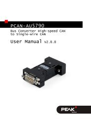
PCAN-GPRS Link 42<br />
PCAN-Diag 2 44<br />
MU-Thermocouple1 CAN 47<br />
Software ...<br />
Development Packages<br />
PCAN-Basic 50<br />
PCAN-Developer 52<br />
PCAN-RP1210 API 55<br />
PCAN-CCP API & PCAN-XCP API 56<br />
Application Software<br />
PCAN-View 57<br />
PLIN-View Pro 58<br />
PCAN-MicroMod Configuration 59<br />
PPCAN-Editor 2 60<br />
PCAN-Trace 61<br />
PCAN-FMS Simulator 2 62<br />
PCAN-Link 64<br />
PCAN-Explorer & Add-ins<br />
PCAN-Explorer 5 65<br />
Plotter Add-in 2 68<br />
CANdb Import Add-in 3 69<br />
Instruments Panel Add-in 3 70<br />
J1939 Add-in 71<br />
PCAN Symbol Editor 72<br />
Accessories ...<br />
Adapters<br />
ISA-PC/104 Adapter 74<br />
PCI-PC/104-Plus Adapter 74<br />
PCI-Express-PCIe/104 Adapter 74<br />
PCAN-Term 75<br />
PCAN-T-Adapter 75<br />
Cables<br />
PCAN-Cable 1 & 2 76<br />
PCAN-Cable 3 77<br />
PCAN-LIN Connection Cable 78<br />
PCAN-Cable OBD-2 79<br />
Education<br />
Serial Bus Simulator 80<br />
PLIN-Slave 81<br />
A constantly updated overview of our products can be found on . . .
Hardware ...<br />
CAN Interfaces<br />
Bus Converter Modules<br />
Microcontroller Hardware<br />
CAN/LIN access for all conventional PC interfaces<br />
Optional with electrical isolation<br />
Linux drivers available free of charge<br />
Converters for use in different physical layer<br />
applications (bus converter modules)<br />
Microcontroller hardware ideal for development,<br />
prototype build, and small batch runs<br />
Configurable modules for control, measured data<br />
recording, and processing<br />
Simple integration into existing networks without<br />
developing additional software<br />
CAN bus diagnostics<br />
All products are conform to CE standards
8<br />
Hardware >> CAN Interfaces<br />
PCAN-USB<br />
CAN Interface for USB<br />
The PCAN-USB adapter enables simple connection<br />
to CAN networks. Its compact plastic casing makes it<br />
suitable for mobile applications.<br />
The opto-decoupled version guarantees galvanic<br />
isolation of up to 500 Volts between the PC and the<br />
CAN side.<br />
The package is also supplied with the CAN monitor<br />
PCAN-View for Windows and the programming<br />
interface PCAN-Basic.<br />
D-Sub Pin Pin assignment<br />
1 Not connected / optional +5V<br />
2 CAN-L<br />
3 GND<br />
4 Not connected<br />
5 Not connected<br />
6 GND<br />
7 CAN-H<br />
8 Not connected<br />
9 Not connected / optional +5V<br />
Specifications<br />
Adapter for USB connection<br />
(USB 1.1, compatible with USB 2.0)<br />
USB voltage supply<br />
Bit rates up to 1 Mbit/s<br />
Time stamp resolution approx. 42 µs<br />
Compliant with CAN specifications<br />
2.0A (11-bit ID) and 2.0B (29-bit ID)<br />
CAN bus connection via D-Sub,<br />
9-pin (in accordance with CiA® 102)<br />
NXP SJA1000 CAN controller,<br />
16 MHz clock frequency<br />
NXP PCA82C251 CAN transceiver<br />
5-Volts supply to the CAN connection can be<br />
connected through a solder jumper, e.g. for<br />
external bus converter<br />
Extended operating temperature range<br />
from -40 to 85 °C (-40 to 185 °F)<br />
Optionally available:<br />
Galvanic isolation on the CAN connection<br />
up to 500 V<br />
www.peak-system.com Products 2012<br />
Ordering information<br />
Designation Part No. Price [€]<br />
PCAN-USB IPEH-002021 195,00<br />
PCAN-USB opto-decoupled IPEH-002022 245,00<br />
(All prices are net prices)<br />
Scope of supply<br />
PCAN-USB in plastic casing<br />
Device drivers for<br />
Windows 7/Vista/XP/Linux (32/64-bit)<br />
Device driver for Windows CE 6.x<br />
(x86 and ARMv4 processor support)<br />
PCAN-View CAN monitor for Windows<br />
(details on page 57)<br />
PCAN-Basic programming interface consisting<br />
of an interface DLL, examples, and header files<br />
for all common programming languages<br />
(details on page 50)<br />
Manual in PDF format
Hardware >> CAN Interfaces<br />
PCAN-USB Pro<br />
CAN/LIN Interface for High-Speed USB 2.0<br />
The PCAN-USB Pro adapter enables simple connection<br />
of a PC to CAN and LIN networks. Two field busses<br />
can be connected at the same time, with up to four<br />
connections available using appropriate adapter<br />
cables (2 x CAN, 2 x LIN). Its robust aluminum casing<br />
makes the PCAN-USB Pro adapter suitable for mobile<br />
applications.<br />
The supplied monitor applications PCAN-View and<br />
PLIN-View Pro as well as the PCAN-Basic and PLIN<br />
programming interfaces round off the range.<br />
Specifications<br />
Adapter for USB connection (USB 2.0)<br />
Transmitting and receiving of CAN and LIN<br />
messages using 2 D-Sub connections (both with<br />
pin assignment for the CAN and LIN bus)<br />
Time stamp resolution 1 µs<br />
Extended operating temperature range<br />
from -40 to 85 °C (-40 to 185 °F)<br />
CAN operation properties:<br />
Bit rates up to 1 Mbit/s<br />
Compliant with CAN specifications<br />
2.0A (11-bit ID) and 2.0B (29-bit ID)<br />
MAX3057ASA CAN transceiver<br />
Each CAN channel is separately opto-decoupled<br />
against USB and LIN<br />
Measurement of bus load including error frames<br />
and overload frames<br />
Induced error generation for incoming and<br />
outgoing CAN messages<br />
LIN operation properties:<br />
Bit rates of 1 – 20 kbit/s<br />
AMIS-30600 LIN transceiver<br />
Both LIN channels (common ground) are<br />
opto-decoupled against USB and CAN<br />
Can be used as a LIN master or slave<br />
(1 ms master task resolution)<br />
Automatic bit rate, frame length, and checksum<br />
type recognition<br />
Autonomous scheduler with support for<br />
unconditional, event, and sporadic frames<br />
Hardware can work through a schedule table<br />
(up to 8 schedule tables can be configured with a<br />
total of 256 slots)<br />
www.peak-system.com Products 2012<br />
D-Sub Pin Pin assignment<br />
1 Not connected / optional +5V<br />
2 CAN-L<br />
3 CAN-GND<br />
4 LIN<br />
5 LIN-GND<br />
6 LIN-GND<br />
7 CAN-H<br />
8 Not connected<br />
9 VBAT<br />
Ordering information<br />
Designation Part No. Price [€]<br />
PCAN-USB Pro IPEH-002061 490,00<br />
(All prices are net prices)<br />
Scope of supply<br />
PCAN-USB Pro in aluminum casing<br />
CAN interface drivers for<br />
Windows 7/Vista/XP and Linux (32/64 bit)<br />
LIN interface drivers for<br />
Windows 7/Vista/XP (32/64 bit)<br />
PCAN-View CAN monitor for Windows<br />
(details on page 57)<br />
PLIN-View Pro LIN monitor for Windows<br />
(details on page 58)<br />
PCAN-Basic programming interface consisting<br />
of an interface DLL, examples, and header files<br />
for all common programming languages<br />
(details on page 50)<br />
PLIN-API programming interface consisting of<br />
an interface DLL, an example, and header files<br />
for all common programming languages<br />
Manual in PDF format<br />
9
10<br />
Hardware >> CAN Interfaces<br />
PCAN-USB Hub<br />
All-in-one USB Adapter for Communication through USB, CAN, and RS-232<br />
The PCAN-USB Hub provides multiple hardware<br />
interfaces through a USB connection. It offers the user<br />
one CAN, two RS-232, and two further USB interfaces.<br />
Its robust aluminum casing makes the PCAN-USB Hub<br />
suitable for mobile applications.<br />
The package is also supplied with the CAN monitor<br />
PCAN-View for Windows and the programming<br />
interface PCAN-Basic.<br />
D-Sub Pin Pin assignment RS-232<br />
1 DCD<br />
2 RxD<br />
3 TxD<br />
4 DTR<br />
5 GND<br />
6 DSR<br />
7 RTS<br />
8 CTS<br />
9 RI<br />
Specifications<br />
High-speed USB 2.0 hub with<br />
• CAN interface, D-Sub 9-pin connector<br />
(in accordance with CiA® 102)<br />
• two RS-232 ports, D-Sub 9-pin connectors<br />
• two High-speed USB 2.0 downstream ports<br />
Passive (bus-powered) hub operation through the<br />
USB port of a PC enables power consumption of<br />
up to 100 mA per USB channel<br />
Active (self-powered) hub operation through the<br />
optional external hub power supply (9 – 36 V)<br />
enables power consumption of up to 500 mA per<br />
USB channel<br />
Guaranteed high bit rates on all channels if a<br />
Full-speed device is connected, thanks to a hub<br />
controller with 4 transaction translators<br />
CAN Bit rates up to 1 Mbit/s<br />
Time stamp resolution approx. 42 µs<br />
Compliant with CAN specifications 2.0A and 2.0B<br />
NXP PCA82C251 CAN transceiver<br />
5-Volt and external power supply at the CAN<br />
connector connectible by solder bridges, e.g. for<br />
external bus converter<br />
Extended operating temperature range<br />
from -40 to 85 °C (-40 to 185 °F)<br />
www.peak-system.com Products 2012<br />
D-Sub Pin Pin assignment CAN<br />
1 Not connected / optional +5V<br />
2 CAN-L<br />
3 CAN-GND<br />
4 Not connected<br />
5 Not connected<br />
6 PWR-GND<br />
7 CAN-H<br />
8 Not connected<br />
9 PWR-OUT<br />
Ordering information<br />
Designation Part No. Price [€]<br />
PCAN-USB Hub IPEH-002004 390,00<br />
(All prices are net prices)<br />
Scope of supply<br />
PCAN-USB Hub in aluminum casing<br />
Mating connector for voltage supply<br />
Device drivers for<br />
Windows 7/Vista/XP/Linux (32/64-bit)<br />
Device driver for Windows CE 6.x<br />
(x86 and ARMv4 processor support)<br />
PCAN-View CAN monitor for Windows<br />
(details on page 57)<br />
PCAN-Basic programming interface consisting<br />
of an interface DLL, examples, and header files<br />
for all common programming languages<br />
(details on page 50)<br />
Manual in PDF format
Hardware >> CAN Interfaces<br />
PCAN-PC Card<br />
CAN Interface for the PC Card Slot<br />
The card allows the connection of a CAN bus to a<br />
laptop or to a desktop PC with a PC Card slot.<br />
The card is available as a single or dual-channel<br />
version. There are also galvanically separated versions<br />
which guarantee galvanic separation up to a maximum<br />
of 100 Volts between the PC and CAN sides.<br />
The package is also supplied with the CAN monitor<br />
PCAN-View for Windows and the programming<br />
interface PCAN-Basic.<br />
Specifications<br />
Card for the PC Card slot<br />
Form factor Type II, maximum 5 mm in height<br />
Bit rates up to 1 Mbit/s<br />
Compliant with CAN specifications<br />
2.0A (11-bit ID) and 2.0B (29-bit ID)<br />
CAN bus connection via D-Sub,<br />
9-pin (in accordance with CiA® 102)<br />
NXP SJA1000 CAN controller,<br />
16 MHz clock frequency<br />
NXP PCA82C251 CAN transceiver<br />
Software option to switch on 5 Volt supply to CAN<br />
connection, e.g. for external bus converter<br />
Operating temperature range<br />
from 0 to 70 °C (32 to 158 °F)<br />
Optionally available:<br />
Single-channel or dual-channel version<br />
Galvanic isolation on the CAN connection up to<br />
100 V, separate for each CAN channel<br />
www.peak-system.com Products 2012<br />
D-Sub Pin Pin assignment<br />
1 Not connected / optional +5V<br />
2 CAN-L<br />
3 GND<br />
4 Not connected<br />
5 Not connected<br />
6 GND<br />
7 CAN-H<br />
8 Not connected<br />
9 Not connected<br />
Ordering information<br />
Designation Part No. Price [€]<br />
PCAN-PC Card Single Ch. IPEH-002090 195,00<br />
PCAN-PC Card Dual Ch.<br />
PCAN-PC Card Single<br />
IPEH-002091 240,00<br />
Channel opto-decoupled<br />
PCAN-PC Card Dual<br />
IPEH-002092 245,00<br />
Channel opto-decoupled IPEH-002093 295,00<br />
(All prices are net prices)<br />
Scope of supply<br />
PCAN-PC Card CAN interface<br />
Device drivers for<br />
Windows 7/Vista/XP/Linux (32/64-bit)<br />
PCAN-View CAN monitor for Windows<br />
(details on page 57)<br />
PCAN-Basic programming interface consisting<br />
of an interface DLL, examples, and header files<br />
for all common programming languages<br />
(details on page 50)<br />
Manual in PDF format<br />
11
12<br />
Hardware >> CAN Interfaces<br />
PCAN-ExpressCard<br />
CAN Interface for the ExpressCard Slot<br />
The PCAN-ExpressCard provides a connection<br />
between a CAN bus and a laptop or desktop PC with an<br />
ExpressCard slot.<br />
The card is available in single and dual-channel<br />
versions. There are also galvanically separated<br />
versions which guarantee galvanic separation up to a<br />
maximum of 300 Volts between the PC and CAN sides.<br />
The package is also supplied with the CAN monitor<br />
PCAN-View for Windows and the programming<br />
interface PCAN-Basic.<br />
Specifications<br />
Card for the ExpressCard slot<br />
Form factor ExpressCard/54<br />
Bit rates up to 1 Mbit/s<br />
Compliant with CAN specifications<br />
2.0A (11-bit ID) and 2.0B (29-bit ID)<br />
CAN bus connection via D-Sub,<br />
9-pin (in accordance with CiA® 102)<br />
NXP SJA1000 CAN controller,<br />
16 MHz clock frequency<br />
NXP PCA82C251 CAN transceiver<br />
Software option to switch a 5-Volts supply to the<br />
CAN connection, e.g. for external bus converter<br />
Operating temperature range<br />
from 0 to 70 °C (32 to 158 °F)<br />
Optionally available:<br />
Single-channel or dual-channel version<br />
Galvanic isolation on the CAN connection up to<br />
300 V, separate for each CAN channel<br />
www.peak-system.com Products 2012<br />
D-Sub Pin Pin assignment<br />
1 Not connected / optional +5V<br />
2 CAN-L<br />
3 GND<br />
4 Not connected<br />
5 Not connected<br />
6 GND<br />
7 CAN-H<br />
8 Not connected<br />
9 Not connected<br />
Ordering information<br />
Designation Part No. Price [€]<br />
PCAN-ExpressCard<br />
Single Ch. IPEH-003000 210,00<br />
PCAN-ExpressCard Dual Ch. IPEH-003001 255,00<br />
PCAN-ExpressCard Single Ch.<br />
galv. isolated IPEH-003002 260,00<br />
PCAN-ExpressCard Dual Ch.<br />
galv. isolated IPEH-003003 355,00<br />
(All prices are net prices)<br />
Scope of supply<br />
PCAN-ExpressCard CAN interface<br />
Device drivers for<br />
Windows 7/Vista/XP/Linux (32/64-bit)<br />
PCAN-View CAN monitor for Windows<br />
(details on page 57)<br />
PCAN-Basic programming interface consisting<br />
of an interface DLL, examples, and header files<br />
for all common programming languages<br />
(details on page 50)<br />
Manual in PDF format
Hardware >> CAN Interfaces<br />
PCAN-PCI<br />
CAN Interface for PCI<br />
The PCAN-PCI card enables the connection of a PC<br />
with PCI slots to CAN networks.<br />
The card is available as a single or dual-channel<br />
version. The opto-decoupled versions also guarantee<br />
galvanic isolation of up to 500 Volts between the PC<br />
and the CAN sides.<br />
The package is also supplied with the CAN monitor<br />
PCAN-View for Windows and the programming<br />
interface PCAN-Basic.<br />
Specifications<br />
PC plug-in card for PCI slots<br />
Bit rates up to 1 Mbit/s<br />
Compliant with CAN specifications<br />
2.0A (11-bit ID) and 2.0B (29-bit ID)<br />
CAN bus connection via D-Sub,<br />
9-pin (in accordance with CiA® 102)<br />
NXP SJA1000 CAN controller,<br />
16 MHz clock frequency<br />
NXP PCA82C251 CAN transceiver<br />
5-Volts supply to the CAN connection can be<br />
connected through a solder jumper, e.g. for<br />
external bus converter<br />
Extended operating temperature range<br />
from -40 to 85 °C (-40 to 185 °F)<br />
Optionally available:<br />
Single-channel or dual-channel version<br />
Galvanic isolation on the CAN connection up to<br />
500 V, separate for each CAN channel<br />
www.peak-system.com Products 2012<br />
D-Sub Pin Pin assignment<br />
1 Not connected / optional +5V<br />
2 CAN-L<br />
3 GND<br />
4 Not connected<br />
5 Not connected<br />
6 GND<br />
7 CAN-H<br />
8 Not connected<br />
9 Not connected / optional +5V<br />
Ordering information<br />
Designation Part No. Price [€]<br />
PCAN-PCI Single Channel IPEH-002064 200,00<br />
PCAN-PCI Dual Channel IPEH-002065 245,00<br />
PCAN-PCI Single<br />
Channel opto-decoupled IPEH-002066 250,00<br />
PCAN-PCI Dual<br />
Channel opto-decoupled IPEH-002067 345,00<br />
(All prices are net prices)<br />
Scope of supply<br />
PCAN-PCI card<br />
Device drivers for<br />
Windows 7/Vista/XP/Linux (32/64-bit)<br />
Device driver for Windows CE 6.x<br />
(x86 and ARMv4 processor support)<br />
PCAN-View CAN monitor for Windows<br />
(details on page 57)<br />
PCAN-Basic programming interface consisting<br />
of an interface DLL, examples, and header files<br />
for all common programming languages<br />
(details on page 50)<br />
Manual in PDF format<br />
13
14<br />
Hardware >> CAN Interfaces<br />
PCAN-PCI Express<br />
CAN Interface for PCI Express<br />
The PCAN-PCI Express card enables the connection of<br />
a PC with PCI Express slots to CAN networks. There<br />
is galvanic isolation of up to 500 Volts between the<br />
computer and CAN sides. The card is available as a<br />
single, dual, or four-channel version.<br />
The package is also supplied with the CAN monitor<br />
PCAN-View for Windows and the programming<br />
interface PCAN-Basic.<br />
Specifications<br />
PC plug-in card (PCIe-x1) for PCI Express slots<br />
Bit rates up to 1 Mbit/s<br />
Compliant with CAN specifications<br />
2.0A (11-bit ID) and 2.0B (29-bit ID)<br />
CAN bus connection via D-Sub,<br />
9-pin (in accordance with CiA® 102)<br />
NXP SJA1000-compatible CAN controller<br />
(FPGA implementation)<br />
NXP PCA82C251 CAN transceiver<br />
Galvanic isolation on the CAN connection up to<br />
500 V, separate for each CAN channel<br />
5-Volts supply to the CAN connection can be<br />
connected through a solder jumper, e.g. for<br />
external bus converter<br />
Extended operating temperature range<br />
from -40 to 85 °C (-40 to 185 °F)<br />
Optionally available:<br />
Single, dual, or four-channel version<br />
www.peak-system.com Products 2012<br />
D-Sub Pin Pin assignment<br />
1 Not connected / optional +5V<br />
2 CAN-L<br />
3 GND<br />
4 Not connected<br />
5 Not connected<br />
6 GND<br />
7 CAN-H<br />
8 Not connected<br />
9 Not connected<br />
Ordering information<br />
Designation Part No. Price [€]<br />
PCAN-PCI Express Single<br />
Channel galv. isolated IPEH-003026 220,00<br />
PCAN-PCI Express Dual<br />
Channel galv. isolated IPEH-003027 280,00<br />
PCAN-PCI Express Four<br />
Channel galv. isolated IPEH-003040 350,00<br />
(All prices are net prices)<br />
Scope of supply<br />
PCAN-PCI Express card<br />
Slot bracket with D-Sub connectors for the<br />
CAN bus (only four-channel version)<br />
Device drivers for<br />
Windows 7/Vista/XP/Linux (32/64-bit)<br />
PCAN-View CAN monitor for Windows<br />
(details on page 57)<br />
PCAN-Basic programming interface consisting<br />
of an interface DLL, examples, and header files<br />
for all common programming languages<br />
(details on page 50)<br />
Manual in PDF format
Hardware >> CAN Interfaces<br />
PCAN-cPCI<br />
CAN Interface for CompactPCI<br />
The PCAN-cPCI card enables the connection of an<br />
industrial computer system with CompactPCI to CAN<br />
networks. There is galvanic isolation of up to 500 Volts<br />
between the computer and CAN sides. The card is<br />
available as a dual or four-channel version.<br />
The package is also supplied with the CAN monitor<br />
PCAN-View for Windows and the programming<br />
interface PCAN-Basic.<br />
Specifications<br />
Extension card with euroboard form factor (3U)<br />
for a CompactPCI system<br />
Bit rates up to 1 Mbit/s<br />
Compliant with CAN specifications<br />
2.0A (11-bit ID) and 2.0B (29-bit ID)<br />
CAN bus connection via D-Sub,<br />
9-pin (in accordance with CiA® 102)<br />
NXP SJA1000 CAN controller,<br />
16 MHz clock frequency<br />
NXP PCA82C251 CAN transceiver<br />
5-Volts supply to the CAN connection can be<br />
connected through a solder jumper, e.g. for<br />
external bus converter<br />
Galvanic isolation on the CAN connection up to<br />
500 V, separate for each CAN channel<br />
Extended operating temperature range<br />
from -40 to 85 °C (-40 to 185 °F)<br />
Optionally available:<br />
Dual or four-channel version<br />
www.peak-system.com Products 2012<br />
D-Sub Pin Pin assignment<br />
1 Not connected / optional +5V<br />
2 CAN-L<br />
3 GND<br />
4 Not connected<br />
5 Not connected<br />
6 GND<br />
7 CAN-H<br />
8 Not connected<br />
9 Not connected / optional +5V<br />
Ordering information<br />
Designation Part No. Price [€]<br />
PCAN-cPCI Dual Channel<br />
opto-decoupled<br />
PCAN-cPCI Four Channel<br />
IPEH-003021 450,00<br />
opto-decoupled IPEH-003022 580,00<br />
(All prices are net prices)<br />
Scope of supply<br />
PCAN-cPCI card<br />
Slot bracket with D-Sub connectors for the<br />
CAN bus (only four-channel version)<br />
Device drivers for<br />
Windows 7/Vista/XP/Linux (32/64-bit)<br />
Device driver for Windows CE 6.x<br />
(x86 and ARMv4 processor support)<br />
PCAN-View CAN monitor for Windows<br />
(details on page 57)<br />
PCAN-Basic programming interface consisting<br />
of an interface DLL, examples, and header files<br />
for all common programming languages<br />
(details on page 50)<br />
Manual in PDF format<br />
15
16<br />
Hardware >> CAN Interfaces<br />
PCAN-miniPCI<br />
CAN Interface for Mini PCI<br />
The PCAN-miniPCI card enables the connection of<br />
embedded PCs and laptops with Mini PCI slots to CAN<br />
networks.<br />
The card is available as a single or dual-channel<br />
version. The opto-decoupled versions also guarantee<br />
galvanic isolation of up to 300 Volts between the PC<br />
and the CAN sides.<br />
The package is also supplied with the CAN monitor<br />
PCAN-View for Windows and the programming<br />
interface PCAN-Basic.<br />
Specifications<br />
CAN interface for the Mini PCI slot<br />
CAN bus connection via connection cable and<br />
D-Sub, 9-pin (in accordance with CiA® 102)<br />
Bit rates up to 1 Mbit/s<br />
Compliant with CAN specifications<br />
2.0A (11-bit ID) and 2.0B (29-bit ID)<br />
NXP SJA1000 CAN controller,<br />
16 MHz clock frequency<br />
TJA1040 CAN transceiver<br />
Space-saving dimensions thanks to<br />
SMD technology<br />
5-Volts supply to the CAN connection can be<br />
connected through a solder jumper, e.g. for<br />
external bus converter<br />
Operating temperature range<br />
from 0 to 70 °C (32 to 158 °F)<br />
Optionally available:<br />
Single-channel or dual-channel version<br />
Galvanic isolation on the CAN connection up to<br />
300 V, separate for each CAN channel<br />
www.peak-system.com Products 2012<br />
D-Sub Pin Pin assignment<br />
1 Not connected / optional +5V<br />
2 CAN-L<br />
3 GND<br />
4 Not connected<br />
5 Not connected<br />
6 GND<br />
7 CAN-H<br />
8 Not connected<br />
9 Not connected<br />
Ordering information<br />
Designation Part No. Price [€]<br />
PCAN-miniPCI Single Ch. IPEH-003044 200,00<br />
PCAN-miniPCI Dual Ch.<br />
PCAN-miniPCI Single Ch.<br />
IPEH-003045 245,00<br />
opto-decoupled<br />
PCAN-miniPCI Dual Ch.<br />
IPEH-003046 250,00<br />
opto-decoupled IPEH-003047 345,00<br />
(All prices are net prices)<br />
Scope of supply<br />
PCAN-miniPCI card<br />
Connection cable incl. D-Sub plug<br />
Device drivers for<br />
Windows 7/Vista/XP/Linux (32/64-bit)<br />
Device driver for Windows CE 6.x<br />
(x86 and ARMv4 processor support)<br />
PCAN-View CAN monitor for Windows<br />
(details on page 57)<br />
PCAN-Basic programming interface consisting<br />
of an interface DLL, examples, and header files<br />
for all common programming languages<br />
(details on page 50)<br />
Manual in PDF format
Hardware >> CAN Interfaces<br />
PCAN-miniPCIe<br />
CAN Interface for PCI Express Mini<br />
The PCAN-miniPCIe card enables the connection of<br />
embedded PCs and laptops with PCI Express Mini slots<br />
to CAN networks. There is galvanic isolation of up to<br />
300 Volts between the computer and CAN sides. The<br />
card is available as a single or dual-channel version.<br />
The package is also supplied with the CAN monitor<br />
PCAN-View for Windows and the programming<br />
interface PCAN-Basic.<br />
Specifications<br />
CAN interface for the PCI Express Mini slot<br />
CAN bus connection via connection cable and<br />
D-Sub, 9-pin (in accordance with CiA® 102)<br />
Bit rates up to 1 Mbit/s<br />
Compliant with CAN specifications<br />
2.0A (11-bit ID) and 2.0B (29-bit ID)<br />
NXP SJA1000-compatible CAN controller<br />
(FPGA implementation)<br />
NXP PCA82C251 CAN transceiver<br />
Galvanic isolation on the CAN connection up to<br />
300 V, separate for each CAN channel<br />
Space-saving dimensions thanks to<br />
SMD technology<br />
Extended operating temperature range<br />
from -40 to 85 °C (-40 to 185 °F)<br />
Optionally available:<br />
Single-channel or dual-channel version<br />
www.peak-system.com Products 2012<br />
D-Sub Pin Pin assignment<br />
1 Not connected<br />
2 CAN-L<br />
3 GND<br />
4 Not connected<br />
5 Not connected<br />
6 GND<br />
7 CAN-H<br />
8 Not connected<br />
9 Not connected<br />
Ordering information<br />
Designation Part No. Price [€]<br />
PCAN-miniPCIe Single Ch. IPEH-003048 230,00<br />
PCAN-miniPCIe Dual Ch. IPEH-003049 290,00<br />
(All prices are net prices)<br />
Scope of supply<br />
PCAN-miniPCIe card<br />
Connection cable incl. D-Sub plug<br />
Device drivers for<br />
Windows 7/Vista/XP/Linux (32/64-bit)<br />
PCAN-View CAN monitor for Windows<br />
(details on page 57)<br />
PCAN-Basic programming interface consisting<br />
of an interface DLL, examples, and header files<br />
for all common programming languages<br />
(details on page 50)<br />
Manual in PDF format<br />
17
18<br />
Hardware >> CAN Interfaces<br />
PCAN-PC/104<br />
CAN Interface for PC/104<br />
The PCAN-PC/104 card enables the connection of one<br />
or two CAN networks to a PC/104 system. Multiple<br />
PCAN-PC/104 cards can easily be operated using<br />
interrupt sharing.<br />
The card is available as a single or dual-channel<br />
version. The opto-decoupled versions also guarantee<br />
galvanic isolation of up to 500 Volts between the PC<br />
and the CAN sides.<br />
The package is also supplied with the CAN monitor<br />
PCAN-View for Windows and the programming<br />
interface PCAN-Basic.<br />
Specifications<br />
Form factor PC/104<br />
Multiple PC/104 cards can be operated in<br />
parallel (interrupt sharing)<br />
14 port and 8 interrupt addresses are available for<br />
configuration using jumpers<br />
Bit rates up to 1 Mbit/s<br />
Compliant with CAN specifications<br />
2.0A (11-bit ID) and 2.0B (29-bit ID)<br />
Connection to CAN bus through D-Sub slot<br />
bracket, 9-pin (in accordance with CiA® 102)<br />
NXP SJA1000 CAN controller,<br />
16 MHz clock frequency<br />
NXP PCA82C251 CAN transceiver<br />
5-Volts supply to the CAN connection can be<br />
connected through a solder jumper, e.g. for<br />
external bus converter<br />
Extended operating temperature range<br />
from -40 to 85 °C (-40 to 185 °F)<br />
Optionally available:<br />
Single-channel or dual-channel version<br />
Galvanic isolation on the CAN connection up to<br />
500 V, separate for each CAN channel<br />
www.peak-system.com Products 2012<br />
D-Sub Pin Pin assignment<br />
1 Not connected / optional +5V<br />
2 CAN-L<br />
3 GND<br />
4 Not connected<br />
5 Not connected<br />
6 GND<br />
7 CAN-H<br />
8 Not connected<br />
9 Not connected / optional +5V<br />
Ordering information<br />
Designation Part No. Price [€]<br />
PCAN-PC/104 Single Ch. IPEH-002054 128,00<br />
PCAN-PC/104 Dual Ch.<br />
PCAN-PC/104 Single<br />
IPEH-002055 149,00<br />
Channel opto-decoupled<br />
PCAN-PC/104 Dual<br />
IPEH-002056 169,00<br />
Channel opto-decoupled IPEH-002057 200,00<br />
(All prices are net prices)<br />
Scope of supply<br />
PCAN-PC/104 card<br />
Slot bracket with D-Sub connectors for<br />
the CAN bus<br />
Device drivers for Windows 7/Vista/XP (32-bit)<br />
and Linux (32/64-bit)<br />
Device driver for Windows CE 6.x<br />
(x86 and ARMv4 processor support)<br />
PCAN-View CAN monitor for Windows<br />
(details on page 57)<br />
PCAN-View CAN monitor for DOS<br />
PCAN-Basic programming interface consisting<br />
of an interface DLL, examples, and header files<br />
for all common programming languages<br />
(details on page 50)<br />
Manual in PDF format
Hardware >> CAN Interfaces<br />
PCAN-PC/104-Plus<br />
CAN Interface for PC/104-Plus<br />
The PCAN-PC/104-Plus card enables the connection of<br />
one or two CAN networks to a PC/104-Plus system. Up<br />
to four cards can be operated, with each piggy-backing<br />
off the next. The CAN bus is connected using a 9-pin<br />
D-Sub plug on the slot bracket supplied.<br />
The card is available as a single or dual-channel<br />
version. The opto-decoupled versions also guarantee<br />
galvanic isolation of up to 500 Volts between the PC<br />
and the CAN sides.<br />
The package is also supplied with the CAN monitor<br />
PCAN-View for Windows and the programming<br />
interface PCAN-Basic.<br />
Specifications<br />
Form factor PC/104<br />
Use of the 120-pin connection for the PCI bus<br />
Up to four cards can be used in one system<br />
Bit rates up to 1 Mbit/s<br />
Compliant with CAN specifications<br />
2.0A (11-bit ID) and 2.0B (29-bit ID)<br />
Connection to CAN bus through D-Sub slot<br />
bracket, 9-pin (in accordance with CiA® 102)<br />
NXP SJA1000 CAN controller,<br />
16 MHz clock frequency<br />
NXP PCA82C251 CAN transceiver<br />
5-Volts supply to the CAN connection can be<br />
connected through a solder jumper, e.g. for<br />
external bus converter<br />
Extended operating temperature range<br />
from -40 to 85 °C (-40 to 185 °F)<br />
Optionally available:<br />
Single-channel or dual-channel version<br />
Galvanic isolation on the CAN connection up to<br />
500 V, separate for each CAN channel<br />
PC/104-ISA stack-through connector<br />
www.peak-system.com Products 2012<br />
D-Sub Pin Pin assignment<br />
1 Not connected / optional +5V<br />
2 CAN-L<br />
3 GND<br />
4 Not connected<br />
5 Not connected<br />
6 GND<br />
7 CAN-H<br />
8 Not connected<br />
9 Not connected / optional +5V<br />
Ordering information<br />
Designation Part No. Price [€]<br />
PCAN-PC/104-Plus Single Ch. IPEH-002094 200,00<br />
PCAN-PC/104-Plus Dual Ch. IPEH-002095 245,00<br />
PCAN-PC/104-Plus Single<br />
Channel opto-decoupled IPEH-002096 250,00<br />
PCAN-PC/104-Plus Dual<br />
Channel opto-decoupled IPEH-002097 345,00<br />
(All prices are net prices)<br />
Scope of supply<br />
PCAN-PC/104-Plus card<br />
Slot bracket with D-Sub connectors for<br />
the CAN bus<br />
Device drivers for<br />
Windows 7/Vista/XP/Linux (32/64-bit)<br />
Device driver for Windows CE 6.x<br />
(x86 and ARMv4 processor support)<br />
PCAN-View CAN monitor for Windows<br />
(details on page 57)<br />
PCAN-Basic programming interface consisting<br />
of an interface DLL, examples, and header files<br />
for all common programming languages<br />
(details on page 50)<br />
Manual in PDF format<br />
19
20<br />
Hardware >> CAN Interfaces<br />
PCAN-PC/104-Plus Quad<br />
Four-Channel CAN Interface for PC/104-Plus<br />
The PCAN-PC/104-Plus Quad card enables the<br />
connection of four CAN networks to a PC/104-Plus<br />
system. Up to four cards can be operated, with each<br />
piggy-backing off the next. The CAN bus is connected<br />
using a 9-pin D-Sub plug on the slot brackets supplied.<br />
There is galvanic isolation of up to 500 Volts between<br />
the computer and CAN sides.<br />
The package is also supplied with the CAN monitor<br />
PCAN-View for Windows and the programming<br />
interface PCAN-Basic.<br />
Specifications<br />
Form factor PC/104<br />
Use of the 120-pin connection for the PCI bus<br />
Up to four cards can be used in one system<br />
Bit rates up to 1 Mbit/s<br />
Compliant with CAN specifications<br />
2.0A (11-bit ID) and 2.0B (29-bit ID)<br />
Connection to CAN bus through D-Sub slot<br />
brackets, 9-pin (in accordance with CiA® 102)<br />
NXP SJA1000-compatible CAN controller<br />
(FPGA implementation)<br />
NXP PCA82C251 CAN transceiver<br />
Galvanic isolation on the CAN connection up to<br />
500 V, separate for each CAN channel<br />
5-Volts supply to the CAN connection can be<br />
connected through a solder jumper, e.g. for<br />
external bus converter<br />
Extended operating temperature range<br />
from -40 to 85 °C (-40 to 185 °F)<br />
Optionally available:<br />
PC/104-ISA stack-through connector<br />
www.peak-system.com Products 2012<br />
D-Sub Pin Pin assignment<br />
1 Not connected / optional +5V<br />
2 CAN-L<br />
3 GND<br />
4 Not connected<br />
5 Not connected<br />
6 GND<br />
7 CAN-H<br />
8 Not connected<br />
9 Not connected / optional +5V<br />
Ordering information<br />
Designation Part No. Price [€]<br />
PCAN-PC/104-Plus Quad IPEH-002099 395,00<br />
(All prices are net prices)<br />
Scope of supply<br />
PCAN-PC/104-Plus Quad card<br />
Two slot brackets with D-Sub connectors for<br />
the CAN bus<br />
Device drivers for<br />
Windows 7/Vista/XP/Linux (32/64-bit)<br />
PCAN-View CAN monitor for Windows<br />
(details on page 57)<br />
PCAN-Basic programming interface consisting<br />
of an interface DLL, examples, and header files<br />
for all common programming languages<br />
(details on page 50)<br />
Manual in PDF format
Hardware >> CAN Interfaces<br />
PCAN-PCI/104-Express<br />
CAN Interface for PCI/104-Express<br />
The PCAN-PCI/104-Express card enables the<br />
connection of one or two CAN networks to a PCI/104-<br />
Express system. Up to three cards can be stacked<br />
together. The CAN bus is connected using a 9-pin<br />
D-Sub plug on the slot bracket supplied.<br />
The card is available as a single or dual-channel<br />
version. The opto-decoupled versions also guarantee<br />
galvanic isolation of up to 500 Volts between the PC<br />
and the CAN sides.<br />
The package is also supplied with the CAN monitor<br />
PCAN-View for Windows and the programming<br />
interface PCAN-Basic.<br />
D-Sub Pin Pin assignment<br />
1 Not connected / optional +5V<br />
2 CAN-L<br />
3 GND<br />
4 Not connected<br />
5 Not connected<br />
6 GND<br />
7 CAN-H<br />
8 Not connected<br />
9 Not connected / optional +5V<br />
Specifications<br />
PCI/104-Express card, 1 lane (x1)<br />
Form factor PC/104<br />
Up to 3 cards can be used in one system<br />
Bit rates up to 1 Mbit/s<br />
Compliant with CAN specifications<br />
2.0A (11-bit ID) and 2.0B (29-bit ID)<br />
Connection to CAN bus through D-Sub slot<br />
bracket, 9-pin (in accordance with CiA® 102)<br />
NXP SJA1000 CAN controller,<br />
16 MHz clock frequency<br />
NXP PCA82C251 CAN transceiver<br />
5-Volts supply to the CAN connection can be<br />
connected through a solder jumper, e.g. for<br />
external bus converter<br />
Extended operating temperature range<br />
from -40 to 85 °C (-40 to 185 °F)<br />
Optionally available:<br />
Single-channel or dual-channel version<br />
Galvanic isolation on the CAN connection up to<br />
500 V, separate for each CAN channel<br />
PCI-104 stack-through connector<br />
www.peak-system.com Products 2012<br />
Ordering information<br />
Designation Part No. Price [€]<br />
PCAN-PCI/104-Express<br />
Single Channel IPEH-003054 210,00<br />
PCAN-PCI/104-Express<br />
Dual Channel IPEH-003055 255,00<br />
PCAN-PCI/104-Express<br />
Single Ch. opto-decoupled IPEH-003056 260,00<br />
PCAN-PCI/104-Express<br />
Dual Ch. opto-decoupled IPEH-003057 355,00<br />
(All prices are net prices)<br />
Scope of supply<br />
PCAN-PCI/104-Express card<br />
Slot bracket with D-Sub connectors for<br />
the CAN bus<br />
Device drivers for<br />
Windows 7/Vista/XP/Linux (32/64-bit)<br />
PCAN-View CAN monitor for Windows<br />
(details on page 57)<br />
PCAN-Basic programming interface consisting<br />
of an interface DLL, examples, and header files<br />
for all common programming languages<br />
(details on page 50)<br />
Manual in PDF format<br />
21
22<br />
Hardware >> CAN Interfaces<br />
PCAN-ISA<br />
CAN Interface for ISA<br />
The PCAN-ISA card enables simple, cost-effective<br />
connection of computer systems with ISA slots to<br />
CAN networks. Multiple PCAN-ISA cards can easily be<br />
operated using interrupt sharing.<br />
The card is available as a single or dual-channel<br />
version. The opto-decoupled versions also guarantee<br />
galvanic isolation of up to 500 Volts between the PC<br />
and the CAN sides.<br />
The package is also supplied with the CAN monitor<br />
PCAN-View for Windows and the programming<br />
interface PCAN-Basic.<br />
Specifications<br />
PC plug-in card for 16-bit ISA slots<br />
Multiple cards can be operated in parallel<br />
in a single PC (interrupt sharing)<br />
13 port and 8 interrupt addresses are available for<br />
configuration using jumpers<br />
Bit rates up to 1 Mbit/s<br />
Compliant with CAN specifications<br />
2.0A (11-bit ID) and 2.0B (29-bit ID)<br />
Connection to CAN bus through D-Sub slot<br />
bracket, 9-pin (in accordance with CiA® 102)<br />
NXP SJA1000 CAN controller,<br />
16 MHz clock frequency<br />
NXP PCA82C251 CAN transceiver<br />
5-Volts supply to the CAN connection can be<br />
connected through a solder jumper, e.g. for<br />
external bus converter<br />
Extended operating temperature range<br />
from -40 to 85 °C (-40 to 185 °F)<br />
Optionally available:<br />
Single-channel or dual-channel version<br />
Galvanic isolation on the CAN connection up to<br />
500 V, separate for each CAN channel<br />
www.peak-system.com Products 2012<br />
D-Sub Pin Pin assignment<br />
1 Not connected / optional +5V<br />
2 CAN-L<br />
3 GND<br />
4 Not connected<br />
5 Not connected<br />
6 GND<br />
7 CAN-H<br />
8 Not connected<br />
9 Not connected / optional +5V<br />
Ordering information<br />
Designation Part No. Price [€]<br />
PCAN-ISA Single Channel IPEH-002074 88,00<br />
PCAN-ISA Dual Channel IPEH-002075 108,00<br />
PCAN-ISA Single Channel<br />
opto-decoupled<br />
PCAN-ISA Dual Channel<br />
IPEH-002076 148,00<br />
opto-decoupled IPEH-002077 200,00<br />
(All prices are net prices)<br />
Scope of supply<br />
PCAN-ISA card<br />
Slot bracket with D-Sub connectors for<br />
the CAN bus<br />
Device drivers for Windows 7/Vista/XP (32-bit)<br />
and Linux (32/64-bit)<br />
Device driver for Windows CE 6.x<br />
(x86 and ARMv4 processor support)<br />
PCAN-View CAN monitor for Windows<br />
(details on page 57)<br />
PCAN-View CAN monitor for DOS<br />
PCAN-Basic programming interface consisting<br />
of an interface DLL, examples, and header files<br />
for all common programming languages<br />
(details on page 50)<br />
Manual in PDF format
Hardware >> CAN Interfaces<br />
PCAN-Dongle<br />
CAN Interface for the Parallel Port<br />
This parallel connection to CAN converter is a<br />
sensible alternative to using a PCAN-USB adapter<br />
for connecting to a CAN network, especially for<br />
older PCs and laptops. Depending on the parallel<br />
interface present, it can be operated in “Multiplex” or<br />
“Enhanced Parallel Port” mode. Power is supplied to<br />
the PCAN-Dongle through a special adapter connected<br />
to the PC's keyboard output.<br />
The opto-decoupled version also guarantees galvanic<br />
isolation of up to 500 Volts between the PC and the<br />
CAN sides.<br />
The package is also supplied with the CAN monitor<br />
PCAN-View for Windows and the programming<br />
interface PCAN-Basic.<br />
Specifications<br />
Logic control by means of integrated CPLD<br />
Supplied in space-saving port adapter casing<br />
D-Sub 25-pin (LPT) to D-Sub 9-pin (CAN)<br />
Software-driven switching from “Multiplex” to<br />
“EPP (Enhanced Parallel Port)” mode<br />
The voltage supply is through the PS/2 keyboard<br />
connection<br />
Bit rates up to 1 Mbit/s<br />
Compliant with CAN specifications<br />
2.0A (11-bit ID) and 2.0B (29-bit ID)<br />
CAN bus connection via D-Sub,<br />
9-pin (in accordance with CiA® 102)<br />
NXP SJA1000 CAN controller,<br />
16 MHz clock frequency<br />
NXP PCA82C251 CAN transceiver<br />
5-Volts supply to the CAN connection can be<br />
connected through a solder jumper, e.g. for<br />
external bus converter<br />
Operating temperature range<br />
from 0 to 60 °C (32 to 140 °F)<br />
Optionally available:<br />
Galvanic isolation on the CAN connection<br />
up to 500 V<br />
www.peak-system.com Products 2012<br />
D-Sub Pin Pin assignment<br />
1 Not connected / optional +5V<br />
2 CAN-L<br />
3 GND<br />
4 Not connected<br />
5 Not connected<br />
6 GND<br />
7 CAN-H<br />
8 Not connected<br />
9 Not connected / optional +5V<br />
Ordering information<br />
Designation Part No. Price [€]<br />
PCAN-Dongle PS/2<br />
PCAN-Dongle PS/2<br />
IPEH-002019 145,00<br />
opto-decoupled IPEH-002020 195,00<br />
(All prices are net prices)<br />
Scope of supply<br />
PCAN-Dongle in plastic casing<br />
Device drivers for Windows 7/Vista/XP (32-bit)<br />
and Linux (32/64-bit)<br />
PCAN-View CAN monitor for Windows<br />
(details on page 57)<br />
PCAN-View CAN monitor for DOS<br />
PCAN-Basic programming interface consisting<br />
of an interface DLL, examples, and header files<br />
for all common programming languages<br />
(details on page 50)<br />
Manual in PDF format<br />
23
24<br />
Hardware >> CAN Interfaces<br />
PCAN-LIN<br />
Interface for LIN, CAN, and RS-232<br />
The PCAN-LIN module enables CAN, LIN, and serial<br />
participants to communicate. The module is supplied<br />
in a plastic casing and includes firmware which<br />
enables data to be exchanged between the different<br />
bus systems. Various modes can be set up with the<br />
aid of configuration software. Then for instance the<br />
module acting as the LIN master can request data and<br />
route the incoming LIN data to the CAN bus and/or the<br />
serial interface. Data can be routed between CAN and<br />
LIN with an ID offset.<br />
Specifications<br />
General-purpose gateway (or router when using<br />
Acceptance Code / Acceptance Mask feature) from:<br />
• RS-232 to LIN (and back)<br />
• CAN to LIN (and back)<br />
• RS-232 to CAN (limited bandwidth)<br />
CAN bit rates up to 1 Mbit/s<br />
LIN bit rates of 1 – 20 kbit/s<br />
Transmitting/receiving LIN 1.x and 2.x frames<br />
Available for use as LIN master or slave<br />
Simulation of LIN slaves. Data can be changed via<br />
CAN frames<br />
Processing a user-definable LIN ID list (scheduler<br />
with limited number of entries, cyclic handling if<br />
required)<br />
Individual LIN frames can be initiated<br />
via CAN or RS-232<br />
Voltage supply from 9 to 30 V<br />
Extended operating temperature range<br />
from -40 to 85 °C (-40 to 185 °F)<br />
Optionally available:<br />
High-speed (ISO 11898-2) or <strong>Low</strong>-speed<br />
(ISO 11898-3) CAN transceiver module<br />
Galvanic isolation between RS-232 and CAN/LIN<br />
up to 1 kV (only for High-speed CAN)<br />
www.peak-system.com Products 2012<br />
Female D-Sub Connector Pin Pin assignment RS-232<br />
1 Not connected<br />
2 T x D (RS-232-level)<br />
3 R x D (RS-232-level)<br />
4 Not connected<br />
5 GND<br />
6 Not connected<br />
7 Not connected<br />
8 Not connected<br />
9 Not connected<br />
Male D-Sub Connector Pin Pin assignment CAN/LIN<br />
1 VBat 9 - 30V (Imax ~ 130mA)<br />
2 CAN-L<br />
3 GND<br />
4 LIN data<br />
5 Not connected<br />
6 GND<br />
7 CAN-H<br />
8 Not connected<br />
9 Not connected<br />
Ordering information<br />
Designation Part No. Price [€]<br />
PCAN-LIN High-speed CAN IPEH-002025 245,00<br />
PCAN-LIN <strong>Low</strong>-speed CAN IPEH-002028 245,00<br />
PCAN-LIN High-speed CAN<br />
opto-decoupled IPEH-002029 295,00<br />
(All prices are net prices)<br />
Scope of supply<br />
PCAN-LIN in plastic casing<br />
Configuration and monitoring tool<br />
PCAN-LIN Config for<br />
Windows 7/Vista/XP (32/64-bit)<br />
Manual in PDF format<br />
Accessories<br />
PCAN-LIN Connection Cable optionally available<br />
(details on page 78)
Hardware >> CAN Interfaces<br />
PCAN-LWL<br />
Optical Coupler for CAN Data Transmission<br />
For use in explosion-proof areas or for EMC<br />
measurements, the PCAN-LWL can be used to replace<br />
a stretch of CAN network with a fibre-optic line at any<br />
point. There are the options of conversion to Highspeed<br />
CAN or <strong>Low</strong>-speed CAN. The modules are<br />
supplied with power externally.<br />
Specifications<br />
LED display for transceiver status<br />
High-speed CAN: AMIS 30660 transceiver, max.<br />
500 kbit/s, switchable 120 Ohm bus termination<br />
<strong>Low</strong>-speed CAN: TJA1054 transceiver, max.<br />
125 kbit/s, switchable 510 Ohm / 5.6 kOhm bus<br />
termination, bus error display<br />
The fibre-optic line consists of a 62.5/125 µm fibreoptic<br />
duplex line with ST connectors<br />
Aluminum casing<br />
CAN bus connection via D-Sub, 9-pin<br />
(in accordance with CiA® 102)<br />
Supply voltage: 6.5 – 30 V<br />
Supply via D-Sub 9 pin, or DC connector (jumper)<br />
Operating temperature range<br />
from 0 to 70 °C (32 to 158 °F)<br />
www.peak-system.com Products 2012<br />
D-Sub Pin Pin assignment<br />
1 Not connected<br />
2 CAN-L<br />
3 GND<br />
4 Not connected<br />
5 Not connected<br />
6 GND<br />
7 CAN-H<br />
8 Not connected<br />
9 VIN (optional)<br />
Ordering information<br />
Designation Part No. Price [€]<br />
PCAN-LWL IPEH-002026 695,00<br />
(All prices are net prices)<br />
Scope of supply<br />
2 CAN to optical waveguide converters<br />
including power supply units<br />
A choice of 5 or 10 m FO cable,<br />
62.5 / 125 µm duplex line ST connector.<br />
Other lengths available on request<br />
Manual in PDF format<br />
Also available with Single-wire CAN transceiver on<br />
request<br />
25
26<br />
Hardware >> CAN Interfaces<br />
PCAN-Optoadapter<br />
Plug-on Adapter for Decoupling CAN Networks<br />
The PCAN-Optoadapter is a universal plug-on adapter<br />
to allow galvanic isolation of High-speed CAN bus<br />
systems.<br />
Its integrated logic means that decoupling can be<br />
installed at any point in the CAN network.<br />
Female D-Sub Connector Pin Pin assignment<br />
1 5V Power supply<br />
2 CAN-L<br />
3 GND<br />
4 Not connected<br />
5 Not connected<br />
6 GND<br />
7 CAN-H<br />
8 Not connected<br />
9 Not connected<br />
Specifications<br />
Plug-on adapter for decoupling the CAN bus for<br />
all <strong>PEAK</strong> CAN interfaces<br />
Optical decoupling and electrical isolation<br />
by DC/DC converters up to 500 V<br />
Bit rates up to 1 Mbit/s<br />
High-speed CAN transceiver NXP TJA1050<br />
CAN bus connection via D-Sub,<br />
9-pin (in accordance with CiA® 102)<br />
Extended operating temperature range<br />
from -40 to 85 °C (-40 to 185 °F)<br />
All <strong>PEAK</strong> CAN interfaces can be set to the supply<br />
voltage required<br />
www.peak-system.com Products 2012<br />
Male D-Sub Connector Pin Pin assignment<br />
1 Not connected<br />
2 CAN-L<br />
3 GND<br />
4 Not connected<br />
5 Not connected<br />
6 GND<br />
7 CAN-H<br />
8 Not connected<br />
9 Not connected<br />
Ordering information<br />
Designation Part No. Price [€]<br />
PCAN-Optoadapter IPEH-002038 75,00<br />
(All prices are net prices)<br />
Scope of supply<br />
Adapter in plastic casing<br />
Manual in PDF format
Hardware >> CAN Interfaces<br />
PCAN-Repeater<br />
Test CAN Repeater with Galvanic Isolation<br />
The PCAN-Repeater creates a connection between two<br />
High-speed CAN busses with galvanic isolation of up<br />
to 5 kV. Both CAN channels are decoupled from each<br />
other and from the power supply. CAN messages are<br />
forwarded 1:1 between the two channels and may be<br />
forwarded unidirectionally if required. LEDs display<br />
the current bus status. With its DIN rail casing and<br />
extended temperature range support, this module is<br />
suitable for use in an industrial environment.<br />
Please note: Due to the CAN protocol, the maximum<br />
length of a CAN bus depends on the bit rate. Therefore,<br />
a bus cannot be extended with the PCAN-Repeater.<br />
The physical total length of the CAN bus is reduced<br />
with each built-in PCAN-Repeater according to its<br />
signal delay.<br />
Specifications<br />
Two High-speed CAN channels (ISO 11898-2)<br />
Galvanic isolation rated up to 5 kV according to<br />
IEC60601-1, between both CAN channels and<br />
between CAN and power supply<br />
Bit rates up to 1 Mbit/s<br />
NXP PCA82C251 CAN transceiver<br />
LEDs display CAN bus load and CAN errors<br />
Each CAN channel can be selectively terminated<br />
Listen-only mode for CAN channel 1 or CAN<br />
channel 2 can be switched selectively<br />
Plastic casing (width: 22.5 mm) for mounting on<br />
a DIN rail<br />
Voltage supply from 8 to 30 V<br />
Extended operating temperature range<br />
from -40 to 85 °C (-40 to 185 °F)<br />
www.peak-system.com Products 2012<br />
Ordering information<br />
Designation Part No. Price [€]<br />
PCAN-Repeater IPEH-004038 180,00<br />
(All prices are net prices)<br />
Scope of supply<br />
PCAN-Repeater in DIN rail plastic casing<br />
3 mating connectors for power supply and<br />
CAN connections<br />
Manual in PDF format<br />
27
28<br />
Hardware >> CAN Interfaces<br />
Chip Solutions<br />
Chip Solutions for the CAN Connection to PCI and PCI Express<br />
PCI Bus<br />
PCI Level<br />
Converter<br />
(optional)<br />
Illustration shows the chip solution for the PCI bus<br />
www.peak-system.com Products 2012<br />
SPI Flash<br />
For the CAN connection of your hardware design we<br />
provide several chip solutions. Based on an FPGA, up<br />
to 4 CAN channels can be implemented via the PCI or<br />
the PCI Express bus.<br />
Aside from the documentation about integrating the<br />
FPGA and the configuration file, a license for the<br />
Windows and Linux device drivers, the CAN monitor<br />
PCAN-View, and the PCAN-Basic API is included in the<br />
scope of supply of each chip.<br />
Specifications<br />
FPGA in a BGA package with 256 balls<br />
(1 mm pitch)<br />
100-percent compatible with the PCI and PCI<br />
Express device drivers and the software from<br />
<strong>PEAK</strong>-<strong>System</strong><br />
SJA1000-compatible CAN controller<br />
Small chip size of 17 x 17 mm (without flash)<br />
Extended operating temperature range<br />
from -40 to 85 °C (-40 to 185 °F)<br />
PCI version:<br />
33 MHz clock rate<br />
32 bit bus width<br />
3.3 V; with level converters also suitable for 5-Volt<br />
PCI bus<br />
Available as four-channel version<br />
Programming<br />
Interface (optional)<br />
FPGA<br />
Reset & Clock Power<br />
CAN<br />
Transceiver<br />
1 ... 4<br />
CAN Bus<br />
1 ... 4<br />
PCI Express version:<br />
PCI Express x1<br />
Bit rates up to 2.5 Gbit/s<br />
Available as dual-channel or four-channel version<br />
Scope of supply<br />
FPGA with configuration file according to the<br />
version:<br />
• PCI Quad Channel<br />
• PCI Express Dual Channel<br />
• PCI Express Quad Channel<br />
Documentation about the application of the FPGA<br />
and a sample circuit diagram<br />
One license per chip for:<br />
Device drivers for Windows 7/Vista/XP (32/64-bit)<br />
and Linux (32/64-bit)<br />
PCAN-View CAN monitor for<br />
Windows 7/Vista/XP (32/64-bit)<br />
(details on page 57)<br />
PCAN-Basic programming interface consisting of<br />
an interface DLL, examples, and header files for all<br />
common programming languages<br />
(details on page 50)<br />
If you are interested and for more information, please<br />
contact info@peak-system.com.
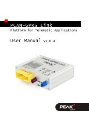
Hardware >> Bus Converter Modules<br />
PCAN-AU5790<br />
Bus Converter High-Speed CAN to Single-Wire CAN<br />
The PCAN-AU5790 bus converter establishes a<br />
connection between a High-speed CAN bus (ISO<br />
11898-2) and a Single-wire CAN bus (SAE J2411). One<br />
of the most important potential applications of the bus<br />
converter is a simple connection between a <strong>PEAK</strong> CAN<br />
interface (e.g. PCAN-USB) and a Single-wire CAN bus.<br />
Female D-Sub Connector Pin Pin assignment High-speed CAN (82C251)<br />
1 5V Power supply<br />
2 CAN-L<br />
3 GND<br />
4 Not connected<br />
5 Not connected<br />
6 GND<br />
7 CAN-H<br />
8 Not connected<br />
9 Not connected / optional +5V<br />
Specifications<br />
There are three different operating modes for the<br />
SW-CAN side which can be set using a sliding<br />
switch. Normal (33.3 kbit/s), High-speed<br />
(83.3 kbit/s) and Wake-up<br />
Indicator LEDs for power supply (red) and wake-up<br />
signals (yellow)<br />
Power supply (5 V, 150 mA) through HS-CAN<br />
connection (a current list of <strong>PEAK</strong> CAN interfaces<br />
with suitable supply voltage is available on<br />
request)<br />
If the power supply has a current output lower<br />
than 150 mA, an additional 12-Volt supply is<br />
needed via the SW-CAN connector<br />
Operating temperature range<br />
from 0 to 70 °C (32 to 158 °F)<br />
www.peak-system.com Products 2012<br />
Male D-Sub Connector Pin Pin assignment Single-wire CAN (AU5790)<br />
1 Not connected<br />
2 Not connected<br />
3 GND<br />
4 Not connected<br />
5 CAN<br />
6 GND<br />
7 Not connected<br />
8 Not connected<br />
9 VBAT<br />
Ordering information<br />
Designation Part No. Price [€]<br />
PCAN-AU5790 IPEH-002040 95,00<br />
(All prices are net prices)<br />
Scope of supply<br />
Adapter in plastic casing<br />
Manual in PDF format<br />
Other transceiver types on request<br />
29
30<br />
Hardware >> Bus Converter Modules<br />
PCAN-B10011S<br />
Bus Converter High-Speed CAN to Truck Trailer CAN<br />
The PCAN-B10011S bus converter establishes a<br />
connection between a High-speed CAN bus<br />
(ISO 11898-2) and a Truck Trailer CAN bus<br />
(ISO 11992-1). One of the most important potential<br />
applications of the bus converter is a simple<br />
connection between a <strong>PEAK</strong> CAN interface<br />
(e.g. PCAN-USB) and a Truck Trailer CAN bus.<br />
Female D-Sub Connector Pin Pin assignment High-speed CAN (82C251)<br />
1 Not connected<br />
2 CAN-L<br />
3 GND<br />
4 Not connected<br />
5 Not connected<br />
6 GND<br />
7 CAN-H<br />
8 Not connected<br />
9 Not connected<br />
Specifications<br />
Direct connection to a High-speed CAN bus<br />
through a D-Sub connector, 9-pin with switchable<br />
termination<br />
Direct connection of the Truck Trailer CAN bus<br />
through a D-Sub connector, 9-pin with switchable<br />
termination (master/slave mode)<br />
Connection of the Truck Trailer CAN<br />
via 9-pin D-Sub connector<br />
Normal or listen-only operating mode<br />
Data transfer rates up to 125 kbit/s<br />
Power supply via Truck Trailer CAN bus<br />
or self-sufficient with power supply unit<br />
Adjustable Truck Trailer system voltage (11 - 26 V)<br />
for power through mains power pack<br />
Status display for power supply and error states<br />
via LEDs<br />
Extended operating temperature range<br />
from -40 to 85 °C (-40 to 185 °F)<br />
www.peak-system.com Products 2012<br />
Male D-Sub Connector Pin Pin assignment Truck Trailer CAN (B10011S)<br />
1 Not connected<br />
2 CAN-L<br />
3 GND<br />
4 Not connected<br />
5 Not connected<br />
6 GND<br />
7 CAN-H<br />
8 Not connected<br />
9 VBAT<br />
Ordering information<br />
Designation Part No. Price [€]<br />
PCAN-B10011S IPEH-002041 195,00<br />
(All prices are net prices)<br />
Scope of supply<br />
Adapter in plastic casing<br />
Power supply unit<br />
Manual in PDF format<br />
Other transceiver types on request
Hardware >> Bus Converter Modules<br />
PCAN-TJA1054<br />
Bus Converter High-Speed CAN to <strong>Low</strong>-Speed CAN<br />
The PCAN-TJA1054 bus converter establishes a<br />
connection between a High-speed CAN bus<br />
(ISO 11898-2) and a <strong>Low</strong>-speed CAN bus (ISO 11898-3).<br />
One of the most important potential applications of the<br />
bus converter is a simple connection between a <strong>PEAK</strong><br />
CAN interface (e.g. PCAN-USB) and a <strong>Low</strong>-speed CAN<br />
bus.<br />
Female D-Sub Connector Pin Pin assignment High-speed CAN (82C251)<br />
1 5V Power supply<br />
2 CAN-L<br />
3 GND<br />
4 Not connected<br />
5 Not connected<br />
6 GND<br />
7 CAN-H<br />
8 Not connected<br />
9 Not connected<br />
Specifications<br />
Adapter from High-speed CAN to <strong>Low</strong>-speed CAN<br />
Bit rates up to 125 kbit/s<br />
CAN transceiver NXP PCA82C251 and TJA1054<br />
Termination resistors for <strong>Low</strong>-speed CAN<br />
can be switched (560 Ohm / 5.66 kOhm)<br />
Power LED<br />
Error LED (<strong>Low</strong>-speed CAN)<br />
CAN bus connection via D-Sub,<br />
9-pin (in accordance with CiA® 102)<br />
Power supply (5 V) through pin 1 of the High-speed<br />
CAN connection. All <strong>PEAK</strong> CAN interfaces can be<br />
set to the required supply via solder jumper<br />
Extended operating temperature range<br />
from -40 to 85 °C (-40 to 185 °F)<br />
www.peak-system.com Products 2012<br />
Male D-Sub Connector Pin Pin assignment <strong>Low</strong>-speed CAN (TJA1054)<br />
1 Not connected<br />
2 CAN-L<br />
3 GND<br />
4 Not connected<br />
5 Not connected<br />
6 GND<br />
7 CAN-H<br />
8 Not connected<br />
9 Not connected<br />
Ordering information<br />
Designation Part No. Price [€]<br />
PCAN-TJA1054 IPEH-002039 85,00<br />
(All prices are net prices)<br />
Scope of supply<br />
Adapter in plastic casing<br />
Manual in PDF format<br />
Other transceiver types on request<br />
31
32<br />
Hardware >> Microcontroller Hardware<br />
PCAN-MicroMod<br />
Universal I/O Module with CAN Interface<br />
The plug-in module PCAN-MicroMod represents<br />
a straightforward possibility to provide electronic<br />
circuits with I/O functionality and a CAN connection.<br />
Configuring is done with a Windows program which<br />
sends the configuration data to the module via CAN.<br />
Several modules can be configured independently on<br />
a CAN bus.<br />
With various PCAN-MicroMod motherboards, it can<br />
be used in device and plant engineering and in the<br />
motor vehicle industry. An optional evaluation board<br />
simplifies the enhancement and development of<br />
custom boards.<br />
PCAN-MicroMod Specifications<br />
8 analog inputs 10 bit Vref 5 V<br />
8 digital inputs and 8 digital outputs<br />
PWM/frequency outputs (1 Hz – 10 kHz)<br />
Maximum of 32 MicroMods in one CAN network<br />
Dimensions: 32 x 35 mm<br />
Extended operating temperature range<br />
from -40 to 85 °C (-40 to 185 °F)<br />
PCAN-MicroMod Evaluation<br />
Specifications<br />
Open-collector output driver for digital outputs<br />
and CMOS PWM outputs<br />
Pickoffs and screw terminals for inputs and<br />
outputs<br />
Switches for status modification of the digital<br />
inputs<br />
Protected digital inputs + LED<br />
4 potentiometers for analog inputs<br />
<strong>Low</strong> pass and resistive divider for voltages > 5 V<br />
Serial interface for firmware updates<br />
Optional <strong>Low</strong>-speed CAN transceiver<br />
Operating temperature range from 0 to 85 °C<br />
(32 to 185 °F)<br />
Dimensions: approx. 100 x 100 mm<br />
www.peak-system.com Products 2012<br />
Ordering information<br />
Designation Part No. Price [€]<br />
PCAN-MicroMod IPEH-002080 98,00<br />
PCAN-MicroMod<br />
Evaluation Board IPEH-002082 110,00<br />
PCAN-MicroMod<br />
Evaluation Kit 1 IPEH-002081 298,00<br />
PCAN-MicroMod<br />
Evaluation Kit 2 IPEH-002079 348,00<br />
(All prices are net prices)<br />
Scope of supply PCAN-MicroMod<br />
PCAN-MicroMod<br />
PCAN-MicroMod Configuration for Windows<br />
(details on page 59)<br />
Manual in PDF format<br />
Scope of supply PCAN-MicroMod Evaluation Kit<br />
PCAN-MicroMod<br />
PCAN-MicroMod Evaluation Board<br />
Power supply unit<br />
PCAN-Dongle PS/2 (Kit 1) / PCAN-USB (Kit 2)<br />
2 m CAN cable with termination (Kit 1 & 2)<br />
PCAN-MicroMod Configuration for Windows<br />
(details on page 59)<br />
Manual and schematic in PDF format
Hardware >> Microcontroller Hardware<br />
PCAN-MicroMod Analog 1 & 2<br />
Application-specific PCAN-MicroMod Motherboards<br />
The motherboards for the PCAN-MicroMod provide<br />
an application-oriented environment. Typical<br />
characteristics of this product group include a wide<br />
supply voltage range and the protective circuit for the<br />
inputs and outputs. CANopen® firmware is available<br />
for all PCAN-MicroMod motherboards.<br />
The motherboards Analog 1 & 2 support general<br />
analog requirements.<br />
Specifications Analog 1<br />
Completely configurable using the Windows<br />
software PCAN-MicroMod Configuration<br />
(details on page 59)<br />
Communication through High-speed CAN<br />
Operating voltage 11 - 26 V<br />
Aluminum casing with spring terminal connectors.<br />
Optional DIN rail fixing option available<br />
Extended operating temperature range<br />
from -40 to 85 °C (-40 to 185 °F)<br />
8 analog inputs with the following properties:<br />
Pull-down circuit<br />
Measuring range unipolar, 0 - 5 V (10 bit)<br />
Measuring range extension optional<br />
Protection against under- and overvoltages<br />
Parallel connection of one digital input each<br />
(alternative use, e.g. for keys)<br />
4 analog outputs with the following properties:<br />
Voltage range 0 - 10 V (based on 8-bit PWM)<br />
Output current 15 mA per channel<br />
Short-circuit protection<br />
www.peak-system.com Products 2012<br />
Specifications Analog 2<br />
Completely configurable using the Windows<br />
software PCAN-MicroMod Configuration<br />
(details on page 59)<br />
Software low pass filter can be adjusted by means<br />
of configuration (1 - 1000 ms)<br />
Communication through High-speed CAN<br />
Operating voltage 11 - 30 V<br />
Aluminum casing with spring terminal connectors.<br />
Optional DIN rail fixing option available<br />
Extended operating temperature range<br />
from -40 to 85 °C (-40 to 185 °F)<br />
8 analog inputs with the following properties:<br />
Bipolar measurement range,<br />
high-resolution +/-10 V (16-bit)<br />
Protection against under- and overvoltages<br />
4 analog outputs with the following properties:<br />
Voltage range 0 - 10 V (based on 12-bit DAC)<br />
Output current 20 mA per channel<br />
Short-circuit protection<br />
33
34<br />
Hardware >> Microcontroller Hardware<br />
PCAN-MicroMod Digital 1 & 2<br />
Application-specific PCAN-MicroMod Motherboards<br />
The motherboards Digital 1 & 2 support general<br />
digital requirements.<br />
Specifications Digital 1 & 2<br />
Completely configurable using the Windows<br />
software PCAN-MicroMod Configuration<br />
(details on page 59)<br />
Communication through High-speed CAN<br />
Operating voltage 8 - 26 V<br />
Aluminum casing with spring terminal connectors.<br />
Optional DIN rail fixing option available<br />
Extended operating temperature range<br />
from -40 to 85 °C (-40 to 185 °F)<br />
8 digital inputs with the following properties:<br />
Pull-up or Pull-down circuit selectable in groups<br />
(3 groups)<br />
Voltage level difference 5 - 18 V<br />
Schmitt trigger behaviour, inverting<br />
<strong>Low</strong> pass behaviour<br />
Parallel switching of one frequency input for 4<br />
digital inputs for an alternative use (e.g. for fast<br />
status changes, counters)<br />
www.peak-system.com Products 2012<br />
5 digital outputs with the following properties:<br />
PCAN-MicroMod Digital 1: 4 <strong>Low</strong>-side switch,<br />
max. 45 V, 0.35 A<br />
PCAN-MicroMod Digital 2: 4 High-side switch,<br />
max. 34 V, 1.1 A<br />
1 fast <strong>Low</strong>-side switch, max. 55 V, 0.75 A<br />
(„frequency output“)<br />
Short-circuit protection<br />
Status LEDs for power supply and digital output
Hardware >> Microcontroller Hardware<br />
PCAN-MicroMod Mix 1<br />
Application-specific PCAN-MicroMod Motherboards<br />
The Mix 1 motherboard combines general analog<br />
and digital requirements with temperature recording<br />
functions.<br />
Specifications<br />
Completely configurable using the Windows<br />
software PCAN-MicroMod Configuration<br />
(details on page 59)<br />
Communication through High-speed CAN<br />
Operating voltage 8 - 26 V<br />
Aluminum casing with spring terminal connectors.<br />
Optional DIN rail fixing option available<br />
Extended operating temperature range<br />
from -40 to 85 °C (-40 to 185 °F)<br />
6 digital inputs with the following properties:<br />
Pull-up or Pull-down circuit selectable in groups<br />
(3 groups)<br />
Voltage level difference 5 - 18 V<br />
Schmitt trigger behavior, inverting<br />
<strong>Low</strong> pass behavior<br />
Parallel switching of one frequency input for 4<br />
digital inputs for an alternative use (e.g. for fast<br />
status changes, counters)<br />
www.peak-system.com Products 2012<br />
2 analog inputs with the following properties:<br />
Pull-down circuit<br />
Measuring range unipolar, 0 to 5 V<br />
Measuring range extension optional<br />
Protection against under- and overvoltages<br />
2 temperature inputs for the connection of<br />
NTC resistors (type EC95F103W), measuring<br />
range 0 - 70 ºC<br />
2 digital outputs (frequency outputs) with the<br />
following properties:<br />
Fast <strong>Low</strong>-side switch, max. 55 V, 0.75 A<br />
Short-circuit protection<br />
35
36<br />
Hardware >> Microcontroller Hardware<br />
PCAN-MicroMod Mix 2<br />
Application-specific PCAN-MicroMod Motherboards<br />
The Mix 2 motherboard combines general analog and<br />
digital requirements with temperature recording<br />
functions.<br />
Specifications<br />
Completely configurable using the Windows<br />
software PCAN-MicroMod Configuration<br />
(details on page 59)<br />
Communication through High-speed CAN<br />
Operating voltage 11 - 26 V<br />
Aluminum casing with spring terminal connectors.<br />
Optional DIN rail fixing option available<br />
Extended operating temperature range<br />
from -40 to 85 °C (-40 to 185 °F)<br />
2 digital inputs with the following properties:<br />
Pull-up or Pull-down circuit selectable in groups<br />
(1 group)<br />
Voltage level difference 5 - 18 V<br />
Schmitt trigger behavior, inverting<br />
<strong>Low</strong> pass behavior<br />
Parallel switching of one frequency input for<br />
an alternative use (e.g. for fast status changes,<br />
counters)<br />
www.peak-system.com Products 2012<br />
3 analog inputs with the following properties:<br />
Pull-down circuit<br />
Measuring range unipolar, 0 - 4.1 V<br />
Measuring range extension optional<br />
<strong>Low</strong> pass behavior<br />
Protection against under- and overvoltages<br />
2 temperature inputs for the connection of one<br />
NTC resistor (type EC95F103W) and one platinum<br />
sensor PT1000, measuring range 0 - 70 °C each<br />
1 digital output with the following properties:<br />
Fast <strong>Low</strong>-side switch, max. 55 V, 0.75 A<br />
Short-circuit protection<br />
1 analog output with the following properties:<br />
Voltage 0 - 10 V on PWM basis at 16-bit resolution<br />
Load capacity: 15 mA, short-circuit proof<br />
1 analog output with the following properties:<br />
Current intensity 0 - 20 mA on PWM basis at<br />
16-bit resolution
Hardware >> Microcontroller Hardware<br />
PCAN-MicroMod Mix 3<br />
Application-specific PCAN-MicroMod Motherboards<br />
The Mix 3 motherboard allows the use of all inputs<br />
and outputs available on the PCAN-MicroMod, which<br />
opens up a wide range of potential applications in the<br />
automotive and industrial sectors.<br />
Specifications<br />
Completely configurable using the Windows<br />
software PCAN-MicroMod Configuration<br />
(details on page 59)<br />
Communication through High-speed CAN<br />
Operating voltage 12 V DC nominal, 8 - 26 V<br />
possible<br />
Plastic casing with Tyco automotive connectors<br />
Extended operating temperature range<br />
from -40 to 85 °C (-40 to 185 °F)<br />
8 analog inputs with the following properties:<br />
0 – 4.1 V (can be expanded using resistive dividers)<br />
10-bit resolution<br />
Protection against voltage dips and surges<br />
<strong>Low</strong> pass behavior<br />
8 digital inputs with the following properties:<br />
Schmitt trigger behavior (Vh = 4 V, Vl = 2.5 V)<br />
Voltage level difference 5 - 18 V<br />
Pull-up or pull-down switching can be set for each<br />
channel<br />
<strong>Low</strong> pass behavior<br />
4 frequency inputs (differences to the digital inputs):<br />
Scanned frequency range 0 – 10 kHz<br />
8 digital outputs with the following properties:<br />
High-side drivers, 350 mA continuous current,<br />
500 mA short-circuit current<br />
4 outputs switchable in low-side drivers,<br />
700 mA continuous current, 1 A short-circuit<br />
current<br />
Short-circuit protection<br />
4 PWM/frequency outputs with the following<br />
properties:<br />
<strong>Low</strong>-side drivers, 350 mA continuous current,<br />
1 A short-circuit current<br />
2 outputs switchable to high-side drivers,<br />
1.5 A continuous current, 5 A short-circuit current<br />
Short-circuit protection<br />
www.peak-system.com Products 2012<br />
Ordering information<br />
Designation Part No. Price [€]<br />
PCAN-MicroMod Analog 1 IPEH-002204 196,00<br />
PCAN-MicroMod Analog 2 IPEH-002207 285,00<br />
PCAN-MicroMod Digital 1 IPEH-002200 196,00<br />
PCAN-MicroMod Digital 2 IPEH-002201 196,00<br />
PCAN-MicroMod Mix 1 IPEH-002202 196,00<br />
PCAN-MicroMod Mix 2 IPEH-002203 196,00<br />
PCAN-MicroMod Mix 3 IPEH-002206 255,00<br />
(All prices are net prices)<br />
Scope of supply<br />
PCAN-MicroMod<br />
PCAN-MicroMod motherboard in casing<br />
including mating connectors<br />
PCAN-MicroMod Configuration for Windows<br />
(details on page 59)<br />
Manual in PDF format<br />
CANopen® firmware is available for all PCAN-<br />
MicroMod motherboards.<br />
37
38<br />
Hardware >> Microcontroller Hardware<br />
PCAN-RS-232<br />
Programmable Converter for RS-232 to CAN<br />
PCAN-RS-232 is a programmable module for the<br />
communication between RS-232 and CAN. The<br />
conversion of data traffic is done via a NXP LPC21<br />
series microcontroller.<br />
The library and WinARM software provided (contains<br />
the GNU Compiler Collection (GCC) for C and C++)<br />
can be used to produce your own firmware and then<br />
transfer it to the module via CAN. This gives a whole<br />
range of options for manipulation, evaluation, filtering,<br />
and routing of the data traffic.<br />
On delivery the PCAN-RS-232 is provided with a demo<br />
firmware that routes from CAN to RS-232 and vice<br />
versa. It allows to configure the data transfer as well<br />
as the hardware with serial control commands. The<br />
corresponding source code is included.<br />
Specifications<br />
NXP LPC21 series microcontroller<br />
(16/32-bit ARM CPU)<br />
External 32 kbyte EEPROM<br />
High-speed CAN channel (ISO 11898-2) with bit<br />
rates from 40 kbit/s to 1 Mbit/s (slower bit rates<br />
available on request)<br />
Data transfer between CAN and RS-232 with a<br />
maximum bit rate of 115,200 bit/s<br />
One digital input and one digital output<br />
(low-active)<br />
2-color LED for status signaling<br />
Connection via a 10-pole screw-terminal strip<br />
(Phoenix)<br />
Voltage supply from 8 to 30 V<br />
Extended operating temperature range<br />
from -40 to 85 °C (-40 to 185 °F)<br />
New firmware can be loaded via CAN interface<br />
To transfer the firmware via CAN, a <strong>PEAK</strong> CAN<br />
interface to connect to your computer is required<br />
www.peak-system.com Products 2012<br />
Ordering information<br />
Designation Part No. Price [€]<br />
PCAN-RS-232 IPEH-002100 110,00<br />
(All prices are net prices)<br />
Scope of supply<br />
PCAN-RS-232 in plastic casing<br />
Windows software (WinARM software with<br />
GNU Compiler Collection for C and C++)<br />
CD with library, programming examples, and<br />
manual in PDF format<br />
On request also available with exposed connector<br />
contacts
Hardware >> Microcontroller Hardware<br />
PCAN-Router<br />
Universal Programmable CAN Converter<br />
The PCAN-Router is a dual-channel CAN<br />
module whose NXP LPC21 series programmable<br />
microcontroller provides the option of using the CAN<br />
messages on both channels on a flexible basis. This<br />
gives a whole range of options for manipulation,<br />
evaluation, filtering, and routing of CAN messages. The<br />
library and WinARM software provided (contains the<br />
GNU Compiler Collection (GCC) for C and C++) can be<br />
used to produce your own firmware and then transfer<br />
it to the module via CAN.<br />
The PCAN-Router is shipped with demonstration<br />
firmware which performs one-to-one forwarding of the<br />
CAN messages between the two CAN channels at 500<br />
kbit/s. The corresponding source code is included.<br />
The module is installed in an sectional aluminum<br />
casing, and is shipped in versions with two D-Sub<br />
connectors or a screw-terminal strip.<br />
Specifications<br />
NXP LPC21 series microcontroller<br />
(16/32-bit ARM CPU)<br />
External 32 kbyte EEPROM<br />
Two High-speed CAN channels (ISO 11898-2) with<br />
bit rates from 40 kbit/s to 1 Mbit/s (slower bit rates<br />
available on request)<br />
An additional LIN channel available on request<br />
Galvanic isolation of the D-Sub connector CAN 2<br />
with the opto-decoupled version<br />
Status signaling with two 2-color LEDs<br />
Connections via two 9-pin D-Sub connectors or<br />
one 10-pole screw-terminal strip (Phoenix)<br />
Aluminum casing, optional with DIN rail fixing<br />
option available<br />
Voltage supply from 8 to 30 V<br />
Extended operating temperature range<br />
from -40 to 85 °C (-40 to 185 °F)<br />
New firmware can be loaded via CAN interface<br />
To transfer the firmware via CAN, a <strong>PEAK</strong> CAN<br />
interface to connect to your computer is required<br />
www.peak-system.com Products 2012<br />
Ordering information<br />
Designation Part No. Price [€]<br />
PCAN-Router with<br />
D-Sub connectors<br />
PCAN-Router with<br />
IPEH-002210 200,00<br />
Phoenix connector IPEH-002210-P 200,00<br />
PCAN-Router opto-decoupled<br />
with D-Sub connectors IPEH-002211 250,00<br />
(All prices are net prices)<br />
Scope of supply<br />
PCAN-Router in aluminum casing<br />
Windows software (WinARM software with<br />
GNU Compiler Collection for C and C++)<br />
CD with library, programming example, and<br />
manual in PDF format<br />
39
40<br />
Hardware >> Microcontroller Hardware<br />
PCAN-Router Pro<br />
4-Channel CAN Router with Data Logger<br />
The PCAN-Router Pro allows the data traffic from up to<br />
four High-speed CAN busses to be connected together.<br />
As well as pure forwarding, the CAN data can be<br />
processed, manipulated, and for example filtered in a<br />
number of different ways. To do this, the behaviour of<br />
the PCAN-Router Pro can be freely configured using<br />
comprehensive Windows software. There are a variety<br />
of function blocks and other settings available to the<br />
user to allow this kind of configuration to be set up.<br />
At the same time, there is a virtual fifth CAN channel<br />
which is responsible for recording all the data traffic to<br />
a CompactFlash card.<br />
Added to this, the modular bus structure allows<br />
flexible adaptation of the CAN channels to the relevant<br />
requirements. For example, <strong>Low</strong>-speed and Singlewire<br />
CAN transceivers are also available on request.<br />
Specifications<br />
4 High-speed CAN channels via plugable<br />
transceiver modules. Alternatively, <strong>Low</strong>-speed,<br />
Single-wire, and opto-decoupled High-speed<br />
modules, as well as High-speed modules without<br />
wake-up function available<br />
Wake-up function using separate input or CAN bus<br />
CAN connections are D-Sub, 9-pin<br />
CAN termination switchable<br />
Detailed configuration with the software<br />
PPCAN-Editor 2 for Windows<br />
Various function blocks for data processing and<br />
manipulation<br />
Configurable beeper<br />
Configurable status LEDs<br />
Recording of CAN data and error frames to a<br />
CompactFlash card<br />
Conversion of logging data to various output<br />
formats using Windows software<br />
Battery buffered realtime clock (RTC), can also be<br />
used for wake-up<br />
Aluminum casing with flange. DIN rail fixing<br />
option available on request<br />
8 - 30 V power supply, protection against<br />
overvoltage and reverse polarity<br />
Extended operating temperature range<br />
from -40 to 85 °C (-40 to 185 °F)<br />
www.peak-system.com Products 2012<br />
Ordering information<br />
Designation Part No. Price [€]<br />
PCAN-Router Pro IPEH-002212 495,00<br />
(All prices are net prices)<br />
Scope of supply<br />
PCAN-Router Pro in aluminum casing<br />
including mating connector for power supply<br />
Configuration software PPCAN-Editor 2 for<br />
Windows (details on page 60)<br />
Conversion software <strong>PEAK</strong>-Converter for<br />
Windows 7/Vista/XP (32/64-bit)<br />
Industrial CompactFlash card (min. 1 GB)<br />
Manual in PDF format<br />
Customization and customer-specific firmware<br />
available on request
Hardware >> Microcontroller Hardware<br />
PCAN-MIO<br />
Universal Controller for CAN Applications<br />
The Multiple Input Output module (MIO) is a universal,<br />
modular controller for use both in the industrial and<br />
automotive fields.<br />
The module has two CAN interfaces as well as multiple<br />
analog and digital inputs and outputs. Incoming<br />
signals can be processed by the microcontroller<br />
and then forwarded to the CAN interfaces or output<br />
channels. For this purpose, the behaviour of the<br />
PCAN-MIO module can be freely configured using a<br />
comprehensive Windows software. A large number of<br />
function blocks and other settings are available to help<br />
the user in creating such a configuration.<br />
A bus structure also enables expansion of the number<br />
of inputs and outputs with additional modules.<br />
Customer-specific requirements can be implemented<br />
in doing so.<br />
Specifications<br />
2 High-speed CAN channels via plugable<br />
transceiver modules. Alternatively, <strong>Low</strong>-speed,<br />
Single-wire, and opto-decoupled High-speed<br />
modules, as well as High-speed modules without<br />
wake-up function available<br />
Wake-up function using separate input or CAN bus<br />
CAN termination switchable<br />
8 digital inputs with low-pass performance<br />
8 digital outputs, 2 of these with PWM capability<br />
6 analog inputs (10 bit, 0 - 10 V)<br />
2 analog outputs (10 bit, 0 - 10 V)<br />
Suitable for use in the automotive field<br />
Detailed configuration with the software<br />
PPCAN-Editor 2 for Windows<br />
Module can store up to 15 configurations<br />
CAN gateway between busses<br />
Individual function blocks for data linkage and data<br />
modification<br />
Available with industrial connectors (Phoenix<br />
spring terminal connectors) or automotive<br />
connectors (Tyco connectors)<br />
Aluminum casing with flange. DIN rail fixing<br />
option available on request<br />
9 - 30 V voltage supply, overvoltage and reverse<br />
polarity protection<br />
Extended operating temperature range<br />
from -40 to 85 °C (-40 to 185 °F)<br />
www.peak-system.com Products 2012<br />
Ordering information<br />
Designation Part No. Price [€]<br />
PCAN-MIO (Industrial) IPEH-002187 480,00<br />
PCAN-MIO Set<br />
(Industrial)<br />
PCAN-MIO<br />
IPEH-002187-Set 650,00<br />
(Automotive)<br />
PCAN-MIO Set<br />
IPEH-002187-A 480,00<br />
(Automotive) IPEH-002187-ASet 650,00<br />
(All prices are net prices)<br />
Scope of supply PCAN-MIO<br />
PCAN-MIO in aluminum casing including<br />
mating connectors<br />
Configuration software PPCAN-Editor 2 for<br />
Windows (details on page 60)<br />
Manual in PDF format<br />
Scope of supply PCAN-MIO Set<br />
PCAN-MIO in aluminum casing including<br />
mating connectors<br />
CAN interface PCAN-USB<br />
Configuration software PPCAN-Editor 2 for<br />
Windows (details on page 60)<br />
Manual in PDF format<br />
Customization on request<br />
41
42<br />
Hardware >> Microcontroller Hardware<br />
PCAN-GPRS Link<br />
Platform for Telematic Applications<br />
The PCAN-Cable OBD-2 cable<br />
is not supplied with the product.<br />
PCAN-GPRS Link is a module for recording and<br />
forwarding vehicle data. There are two freely<br />
programmable microcontrollers within the unit which<br />
process internal vehicle data.<br />
The PCAN-GPRS Link is provided as a development<br />
platform for telematic applications. An API allows<br />
simple integration within a specific application<br />
environment. The PCAN-GPRS Link supports<br />
the evaluation of FMS and Bus FMS data (Fleet<br />
Management <strong>System</strong>). This produces consumptionrelated<br />
vehicle data. The DTCO info interface also<br />
allows the connection and processing of a digital tacho<br />
with access to information such as driver identification<br />
and driver working time. The GPS module can be<br />
used to determine location and output the direction of<br />
travel.<br />
www.peak-system.com Products 2012<br />
There is an optional expansion to allow any volume of<br />
additional data to be processed, output and recorded.<br />
These include temperature and movement sensors,<br />
barcode scanners, RFID readers, displays, and WiFi or<br />
Bluetooth connections.<br />
The PCAN-GPRS Link has ECE type approval (E1),<br />
which guarantees its problem–free use in vehicles.<br />
The PCAN-GPRS Link is supplied with a programming<br />
example in the form of a Linux daemon for x86 Debian.<br />
This daemon receives the data from the PCAN-GPRS<br />
Link and writes them to a mySQL database. Data can<br />
then be visualized using a php script based on Google<br />
Maps* and AJAX. Output includes the FMS and OBD-2<br />
data and positions of all modules connected to the<br />
database.
Hardware >> Microcontroller Hardware<br />
Specifications<br />
Dualcore ARM7 (core) and ARM9 (GPRS) system<br />
Recording of all data to internal flash memory<br />
(maximum 32 GB)<br />
E1 type approval<br />
Operating voltage 6 – 32 V DC<br />
Extended operating temperature range<br />
from -40 to 85 °C (-40 to 185 °F)<br />
U-blox 5 GPS module with 50 channels and over<br />
1 million correlators. Position accuracy 2.5 m CEP<br />
at -130 dBm<br />
Data transfer via GPRS or CSD<br />
Wavecom GPRS class 10 quad-band modem<br />
Handling of DTCO and FMS data<br />
Handling of OBD-2 data via CAN<br />
(complete PID support not ensured)<br />
CiA® 447 and J1939 protocol support on request<br />
Firmware update via GPRS<br />
Two High-speed CAN channels (ISO 11898-2) with<br />
bit rates of 40 kbit/s to 1 Mbit/s<br />
Two digital inputs and one digital output<br />
One UART V.24<br />
www.peak-system.com Products 2012<br />
Ordering information<br />
Designation Part No. Price [€]<br />
PCAN-GPRS Link IPEH-004000 350,00<br />
PCAN-GPRS Link Set IPEH-004000-EVAL 440,00<br />
(All prices are net prices)<br />
Scope of supply PCAN-GPRS Link<br />
PCAN-GPRS Link in aluminum casing<br />
Tyco mating connector including<br />
crimp contacts<br />
CD with library, programming example, and<br />
manual in PDF format<br />
Scope of supply PCAN-GPRS Link Set<br />
* Use of Google Maps is<br />
subject to the licensing terms and<br />
conditions as specified by Google Inc. and<br />
is only in limits free of charge.<br />
PCAN-GPRS Link in aluminum casing<br />
Preconfigured cable set<br />
Additional set of crimp contacts<br />
1 GB memory card installed<br />
JTAG adapter<br />
GPRS/GPS combination antenna<br />
CD with library, programming example, and<br />
manual in PDF format<br />
43
44<br />
Hardware >> Microcontroller Hardware<br />
PCAN-Diag 2<br />
Handheld CAN Bus Diagnostics Unit<br />
PCAN-Diag 2 is a handheld diagnostics unit with a<br />
wide range of functions to allow investigation of a<br />
CAN bus, such as detection of the CAN bit rate, bus<br />
load measurement, and termination measurement. As<br />
well as receiving CAN messages, it can transmit either<br />
individual messages or entire sequences of them. In<br />
addition, the internal memory card allows tracing and<br />
playback of the CAN traffic.<br />
The integrated two-channel oscilloscope enables<br />
visualization of CAN signals. Single CAN IDs and<br />
various events can be used as triggers. The CAN<br />
frames are decoded from the analog signal, for<br />
example, to detect errors in the frame.<br />
Incoming CAN messages can be displayed as symbols<br />
for clear and easy allocation. The PCAN Symbol Editor<br />
software supplied with this product enables convenient<br />
creation of the symbol files needed for this feature.<br />
Output is through a color display with OLED<br />
technology which allows excellent readability even<br />
when there is strong ambient light. The user selects<br />
and operates the individual diagnostic functions using<br />
www.peak-system.com Products 2012<br />
a push dial. As an alternative to High-speed CAN, CAN<br />
transceiver modules are also available on request for<br />
connecting to <strong>Low</strong>-speed or Single-wire CAN.<br />
Specifications<br />
High-speed CAN (ISO 11898-2), CAN transceiver<br />
module available on request for <strong>Low</strong>-speed CAN<br />
(ISO 11898-3) or Single-wire CAN (SAE J2411)<br />
CAN connection is D-Sub, 9-pin<br />
Select from fixed and 8 user-defined bit rates<br />
OLED display with 320 x 240 pixel resolution<br />
Power supply via batteries (4 x 1.5 V AA) or using<br />
supply unit provided (low-voltage socket on unit)<br />
Internal memory card (min. 1 GB) for saving<br />
projects. Can also be used as a USB mass storage<br />
device when connected to a PC<br />
Operating temperature range<br />
from 0 to 50 °C (32 to 122 °F)
Hardware >> Microcontroller Hardware<br />
Overview of functions<br />
Symbolic display of incoming CAN messages<br />
using symbol files, taking into account enums<br />
(lists of values), multiplexers, and ID ranges<br />
Symbol files can be set up using the PCAN Symbol<br />
Editor software supplied with this product<br />
Recording of incoming CAN messages to the<br />
internal memory card<br />
Playback of trace files<br />
Conversion of trace data to various output formats<br />
using Windows software<br />
Transmitting individual CAN frames or<br />
CAN frame lists<br />
Decimal, hexadecimal, or binary entering of<br />
CAN data. Data change of a single transmission<br />
message during runtime<br />
Measurement of CAN bus load, displayed by<br />
means of time diagram<br />
Bus-load time diagrams can be saved as Bitmap<br />
screenshots<br />
Measurement of CAN termination for High-speed<br />
CAN bus, even while the system is running<br />
Switchable CAN termination for the connected<br />
bus, depending on the transceiver module used<br />
Voltage measurement for all pins of the CAN<br />
connector (D-Sub)<br />
www.peak-system.com Products 2012<br />
Management of device configuration, transmit<br />
lists, symbol files, and all recorded data<br />
(screenshots, trace, and CSV files) in projects<br />
Features of the software PCAN-Diag Editor for<br />
Windows, supplied with this product:<br />
Convenient configuration of all available device<br />
settings<br />
Compilation of transmit lists<br />
Configuration of up to 8 bit rates per project<br />
Device configuration, transmit lists, and associated<br />
symbol files can be saved in projects<br />
Projects can be transferred to the memory card of<br />
the PCAN-Diag 2 using an USB connection<br />
Note about the trace function<br />
With the firmware 1.5.0 tracing of CAN messages is<br />
now possible. In order to record also at a high bit rate<br />
together with high CAN bus load, a hardware upgrade<br />
is available for devices that had been delivered before<br />
February 2012. If you are interested and for further<br />
information, please contact info@peak-system.com.<br />
45
46<br />
Hardware >> Microcontroller Hardware<br />
Oscilloscope functions<br />
Oscilloscope with two independent measurement<br />
channels, each with a maximum sample rate<br />
of 20 MHz<br />
Display of the CAN-High and the CAN-<strong>Low</strong> signals<br />
as well as the difference of both signals<br />
Inspection of external signals (with frequencies up<br />
to 1 MHz) with a probe via the BNC connection<br />
Trigger configuration to frame start, frame end,<br />
CAN errors, or individual CAN frames based on<br />
their CAN ID<br />
External measurement devices can be triggered<br />
using the BNC connector<br />
Depiction of raw CAN frames<br />
Decoding of CAN frames from the recorded<br />
signal trace<br />
Current view can be saved as a Bitmap screenshot<br />
Memory depth can be set to up to 64 kSamples<br />
Recorded sample data can be saved as a CSV file<br />
Extensive zoom functions<br />
Time measurement with a resolution of up to 50 ns<br />
www.peak-system.com Products 2012<br />
Ordering information<br />
Designation Part No. Price [€]<br />
PCAN-Diag 2 IPEH-002069 765,00<br />
(All prices are net prices)<br />
Scope of supply<br />
PCAN-Diag 2 in plastic casing<br />
Configuration software PCAN-Diag Editor for<br />
Windows 7/Vista/XP (32/64-bit)<br />
PCAN Symbol Editor for Windows<br />
(details on page 72)<br />
Conversion software <strong>PEAK</strong>-Converter for<br />
Windows 7/Vista/XP (32/64-bit)<br />
Batteries (4 x 1.5 V AA)<br />
Micro USB connector cable<br />
Power supply unit with changeable plugs for<br />
Euro, U.S., and UK<br />
Manual in PDF format<br />
Printed quick start guide<br />
Delivered in shockproof plastic box
Hardware >> Microcontroller Hardware<br />
MU-Thermocouple1 CAN<br />
Configurable <strong>System</strong> for Data Acquisition and Data Processing<br />
The Thermocouple Measuring Unit offers connections<br />
for 8 thermoelements for different temperature ranges<br />
(J, K, T).<br />
Measurement data can be pre-processed<br />
and transmitted via CAN bus using a central<br />
microcontroller. Configuration work involves using<br />
Windows software on a computer connected to the<br />
same CAN bus.<br />
Specifications<br />
8 Mini sockets for thermocouple types J, K, and<br />
T (depending on the assembly of measuring<br />
modules at delivery)<br />
4 galvanically isolated measuring modules, each<br />
with 2 thermocouple sockets of the same type<br />
Measuring ranges: • J: -210 to +1121 °C<br />
• K: -200 to +1370 °C<br />
• T: -200 to +400 °C<br />
Measurement accuracy: 0.2 %<br />
Accuracy of the reference sensors: typically<br />
±0.5 K, max. ±1.0 K at +25 °C ambient temperature<br />
Resolution for temperature data at CAN<br />
communication: 1/16 °C<br />
High-speed CAN connection (ISO 11898-2) for data<br />
transfer and configuring, galvanic isolation<br />
up to 500 V<br />
Basic configuration with the Windows software<br />
Thermocouple Configuration<br />
Advanced configuration with the Windows<br />
software PPCAN-Editor 2<br />
Preprocessing of readings possible with integrated<br />
microcontroller<br />
Aluminum casing with flange. DIN rail fixing<br />
option available on request<br />
Extended operating temperature range<br />
from -40 to 85 °C (-40 to 185 °F)<br />
www.peak-system.com Products 2012<br />
Ordering information<br />
Designation Part No. Price [€]<br />
MU-Thermocouple1 CAN IPEH-002205 560,00<br />
(All prices are net prices)<br />
Scope of supply<br />
MU-Thermocouple1 CAN in aluminum casing<br />
Mating connector for voltage supply<br />
Configuration software<br />
Thermocouple Configuration for<br />
Windows 7/Vista/XP (32/64-bit)<br />
(Configuration requires a <strong>PEAK</strong> CAN interface)<br />
Configuration software PPCAN-Editor 2 for<br />
Windows (details on page 60)<br />
Manual in PDF format<br />
47
48<br />
Hardware<br />
PCAN-USB<br />
The most recent versions of our free applications, device drivers, and APIs are available at our<br />
Download web page.<br />
The Support section contains an overview of the current versions of our software products, drivers, and<br />
APIs, along with change histories.<br />
Visit our Linux website for the latest Linux device drivers, documentation, change history, and additional<br />
information.<br />
www.peak-system.com Products 2012<br />
Over the last few years, we have continuously expanded the range of<br />
driver support options available for our CAN interfaces. For example, we<br />
have added support for Windows CE 6.x for x86 and ARMv4 processors,<br />
alongside 64-bit support, which is becoming increasingly important.<br />
For an overview of the operating systems supported, please see the table<br />
below, released December 05, 2012. For more recent information, please<br />
see our website.<br />
Windows Linux<br />
XP Vista 7 CE 6.x<br />
32 64 32 64 32 64 ARM x86 32 64<br />
PCAN-USB Pro - -<br />
PCAN-USB Hub<br />
PCAN-PC Card - -<br />
PCAN-ExpressCard - -<br />
PCAN-PCI<br />
PCAN-PCI Express - -<br />
PCAN-cPCI<br />
PCAN-miniPCI<br />
PCAN-miniPCIe - -<br />
PCAN-PC/104 - - -<br />
PCAN-PC/104-Plus<br />
PCAN-PC/104-Plus Quad - -<br />
PCAN-PCI/104-Express - -<br />
PCAN-ISA - - -<br />
PCAN-Dongle - - - - -
Software ...<br />
Development Packages<br />
Application Software<br />
PCAN-Explorer & Add-ins<br />
<strong>PEAK</strong>-<strong>System</strong> Technik GmbH designs customerspecific<br />
software for PC and embedded systems.<br />
We support you from the idea through to the<br />
finished product<br />
Specification<br />
Technical analysis<br />
Development<br />
Test<br />
Documentation<br />
Delivery<br />
Support
50<br />
Software >> Development Packages<br />
PCAN-Basic<br />
CAN Software API for Windows<br />
The PCAN-Basic API (application programming<br />
interface) enables easy development of powerful<br />
software with CAN support. It includes all of the<br />
functions that an application needs in order to<br />
communicate with PCAN PC hardware. The crossoperating-system<br />
design makes it possible to easily<br />
port software projects between platforms.<br />
PCAN-Basic consists of the actual device driver and an<br />
interface DLL, which provides the API functions.<br />
As the successor to PCAN-Light, PCAN-Basic offers<br />
increased functionality and extended language<br />
support. It provides various functions for developers<br />
under C++, C#, C++/CLR, Delphi, VB.NET, Java, and<br />
Python 2.6.<br />
Features<br />
Supports Windows 7/Vista/XP (32/64-bit) and<br />
Windows CE 6.x operating systems<br />
Multiple <strong>PEAK</strong>-<strong>System</strong> applications and your own<br />
can be operated on a physical CAN channel at the<br />
same time<br />
Use of a single DLL for all supported<br />
hardware types<br />
Use of up to 8 channels for each hardware unit<br />
(depending on the <strong>PEAK</strong> CAN interface used)<br />
Simple switching between channels of a<br />
<strong>PEAK</strong> CAN interface<br />
Driver-internal buffering of 32,768 messages per<br />
CAN channel<br />
Precision of time stamps on received messages<br />
up to 1 µs (depending on the <strong>PEAK</strong> CAN interface<br />
used)<br />
Access to specific hardware parameters, such as<br />
listen-only mode<br />
Notification of the application through Windows<br />
events when a message is received<br />
www.peak-system.com Products 2012<br />
Extended system for debugging operations<br />
Multilingual debugging output<br />
Output language depends on operating system<br />
Debugging information can be defined individually<br />
Note: ISA and parallel port CAN interfaces<br />
only support 32-bit<br />
PCAN-Basic for Windows CE<br />
<strong>PEAK</strong>-<strong>System</strong> provides the PCAN-Basic API to allow<br />
the development of your own CAN applications for<br />
Windows CE 6.x. Programmers can use the languages<br />
C++, C#, and VB.NET.<br />
PCAN-Basic for Linux<br />
A Linux version of the PCAN-Basic API is currently<br />
being developed and will be available soon.
Software >> Development Packages<br />
Functions<br />
Connection:<br />
Initialize: Initialize hardware, set the bit rate,<br />
log on at the driver<br />
Uninitialize: Log off from the driver<br />
Configuration:<br />
SetValue: Setup of hardware parameters such<br />
as debug log, listen-only, and autoreset<br />
FilterMessages: Register messages to be received<br />
Information:<br />
GetValue: Read out DLL and API information<br />
GetStatus: Read out CAN bus status information<br />
GetErrorText: Get an error code description<br />
CAN communication:<br />
Read: Read a CAN message or status incl.<br />
time stamp<br />
Write: Transmit a CAN message<br />
(11/29-bit ID and RTR possible)<br />
Reset: Clear the transmit and receive buffer<br />
www.peak-system.com Products 2012<br />
Ordering information<br />
Designation Price [€]<br />
PCAN-Basic free of charge<br />
Scope of supply<br />
Interface DLL, examples, and header files for<br />
all common programming languages<br />
Documentation in HTML Help format<br />
The current version …<br />
… is available on the product CD<br />
(supplied with our hardware)<br />
… can be downloaded from the Internet free<br />
of charge at www.peak-system.com<br />
<strong>System</strong> requirements<br />
Windows 7/Vista/XP (32/64-bit) or<br />
Windows CE 6.x<br />
At least 512 <strong>MB</strong> RAM and 1 GHz CPU<br />
51
52<br />
Software >> Development Packages<br />
PCAN-Developer<br />
CAN Development Package for Windows 7/Vista/XP<br />
PCAN is a flexible system for planning, developing,<br />
and applying CAN networks. Windows Kernel drivers<br />
are the basis for communication between PCs and<br />
external hardware via a CAN bus. These form the<br />
core of a complete CAN network environment on a PC<br />
running Windows.<br />
This device driver manages the whole data traffic for<br />
all the hardware connected to the PC. The interface<br />
to the user or operator of a hardware device, which is<br />
connected to a CAN network, is formed by so-called<br />
PCAN-Clients. These enable process quantities to be<br />
displayed and influenced as necessary. The driver<br />
allows multiple clients to be connected and these are<br />
able to communicate with CAN busses. It supports<br />
various hardware components that are based on NXP’s<br />
SJA1000 CAN controller.<br />
The following features apply to PCAN-Client programs,<br />
networks, and hardware:<br />
A Client can be connected to more than one<br />
network<br />
A network supports multiple Clients<br />
A hardware device belongs to one network only<br />
A network may have exactly one hardware device<br />
assigned to it, or none at all<br />
When a Client transmits, the message is passed<br />
via hardware to the external bus and to all the<br />
other Clients<br />
If a message is received via the hardware, it is<br />
received by all Clients<br />
Multiple networks may be defined per hardware<br />
device<br />
The PCAN-API interface DLL enables software<br />
developers to use these features.<br />
www.peak-system.com Products 2012<br />
PCAN-Developer includes a single user license for<br />
the development package and a distribution license<br />
for the PCAN-Developer redistributable. This package<br />
includes the API DLLs as well as the software products<br />
PCAN-View, PCAN-CPL, PCAN-Nets Configuration, and<br />
PCAN-Status Display.<br />
For the API and the software you will receive for the<br />
duration of two years all updates and free support,<br />
from our hotline or the forum for developers working<br />
with PCAN-Developer.<br />
Example network<br />
Client A Client B Hardware 1<br />
Gateway<br />
Net 1<br />
Client C Client D Hardware 2<br />
Net 2<br />
Client E Hardware 3<br />
Net 3<br />
Internal network<br />
Client F Client G Client H<br />
Net 4<br />
External<br />
CAN bus „A“,<br />
e.g. PCAN-USB<br />
External<br />
CAN bus „B“,<br />
e.g. PCAN-PCI<br />
External<br />
CAN bus „C“,<br />
e.g. PCAN-cPCI
Software >> Development Packages<br />
Features<br />
Supports Windows 7/Vista/XP (32/64-bit)<br />
operating systems<br />
Use of a Windows DLL for 32-bit or 64-bit as<br />
programming interface (API) for all supported<br />
hardware types<br />
Up to 32 applications can be operated per physical<br />
CAN channel at the same time<br />
Use of up to 16 channels for each hardware unit<br />
Driver-internal buffering of 32,768 messages per<br />
Client. Buffer size can be configured via the API<br />
Precision of time stamps on received messages<br />
up to 1 µs (depending on the <strong>PEAK</strong> CAN interface<br />
used)<br />
Hardware configuration using the control panel<br />
or application<br />
Simulated CAN communication between<br />
applications via Clients<br />
Configuration of single-shot and self-receiverequest<br />
transmissions<br />
Access to all available hardware parameters such<br />
as listen-only mode<br />
Interrupt-driven reception of CAN messages from<br />
the hardware into a FIFO buffer within the driver,<br />
complete with time stamp<br />
Notification of the application through Windows<br />
events when a message is received<br />
Supports CAN specifications 2.0A (11-bit ID) and<br />
2.0B (29-bit ID)<br />
www.peak-system.com Products 2012<br />
Control of the transmission timing by specifying<br />
time stamps when transmitting messages<br />
Comprehensive programming manual (HTML Help<br />
format) and runnable sample source code<br />
Collection of tools for CAN system configuration,<br />
parameterization, and visualization<br />
Ordering information<br />
Designation Part No. Price [€]<br />
PCAN-Developer IPES-002070 1.640,00<br />
(All prices are net prices)<br />
Scope of supply<br />
PCAN-API<br />
PCAN-Developer license package<br />
Software: PCAN-View, PCAN-CPL, PCAN-Nets<br />
Configuration, and PCAN-Status Display<br />
Header files, units, and examples<br />
Documentation in HTML Help format<br />
<strong>System</strong> requirements<br />
Windows 7/Vista/XP (32/64-bit)<br />
At least 512 <strong>MB</strong> RAM and 1 GHz CPU<br />
Note: ISA and parallel port CAN interfaces<br />
only support 32-bit<br />
53
54<br />
Software >> Development Packages<br />
* Information on PCAN-API and the Clients can be found on page 52.<br />
www.peak-system.com Products 2012<br />
We offer various APIs (application programming interfaces) for<br />
developing CAN applications, including our PCAN-API, which<br />
is included in the PCAN-Developer package and the free PCAN-<br />
Basic API. Our PCAN-API, PCAN-Basic, PCAN-Light, and PCAN-<br />
RP1210 programming interfaces enable creation of 32-bit and<br />
64-bit applications.<br />
This section includes a direct side-by-side comparison of our<br />
development packages.<br />
PCAN-Basic PCAN-Developer<br />
Based on the API PCAN-Basic API PCAN-API<br />
Supports Windows 7/Vista/XP (32/64-bit)<br />
operating systems<br />
Supports all <strong>PEAK</strong> CAN interfaces<br />
(ISA and parallel port CAN interfaces<br />
only support 32-bit)<br />
Maximum number of CAN channels supported 8 16<br />
Maximum number of applications per<br />
physical CAN channel<br />
Extended information through hardware parameters -<br />
Precision of time stamps on received messages<br />
(depending on the <strong>PEAK</strong> CAN interface used)<br />
Control of transmission time by time-stamping<br />
outgoing messages<br />
Notification of the application through Windows<br />
events when a message is received<br />
A single application of your<br />
own and applications by<br />
<strong>PEAK</strong>-<strong>System</strong><br />
32<br />
1 µs 1 µs<br />
Driver-internal message buffer 32,768 per CAN channel 32,768 per Client*<br />
Simulated CAN communication between<br />
the applications<br />
One interface for all <strong>PEAK</strong> CAN interfaces (one DLL) (one DLL)<br />
Hotline support for developers -<br />
-<br />
-<br />
Hardware configuration Via application Via control panel and<br />
application<br />
Hardware reset during an<br />
active connection<br />
Freely definable message filter One filter for each CAN channel One filter per Client*<br />
Licensing License for PCAN-Basic API<br />
included with hardware<br />
-<br />
Unlimited licenses for<br />
PCAN-API<br />
Software supplied PCAN-View PCAN-View<br />
PCAN-CPL<br />
PCAN-Nets Configuration<br />
PCAN-Status Display
Software >> Development Packages<br />
PCAN-RP1210 API<br />
RP1210 Development Package and RP1210 Connectivity to <strong>PEAK</strong> CAN Interfaces<br />
The Recommended Practice 1210 was defined by<br />
the Technology and Maintenance Council (TMC)<br />
as a standardized API for communication between<br />
Windows applications and communication networks in<br />
vehicles.<br />
The PCAN-RP1210 API by <strong>PEAK</strong>-<strong>System</strong> is an<br />
implementation of RP1210 version A with support for<br />
CAN and SAE J1939 networks. Thus the API makes<br />
it possible to develop own RP1210 applications and<br />
to use already existing ones with CAN interfaces by<br />
<strong>PEAK</strong>-<strong>System</strong>.<br />
With the PCAN-RP1210 API you get a single user<br />
license for the development package and for the<br />
RP1210 connectivity to <strong>PEAK</strong> CAN interfaces. The<br />
PCAN-Developer RP1210 Extension contains a<br />
distribution license for the PCAN-RP1210 API DLLs.<br />
With this extension your customers can install the<br />
DLLs via the PCAN-Developer redistributable package.<br />
Features<br />
RP1210 (Version A) implementation according to<br />
the specification by TMC<br />
Development of own RP1210 applications<br />
Use of RP1210 applications with <strong>PEAK</strong><br />
CAN interfaces<br />
Support of CAN and SAE J1939 networks<br />
Note: The PCAN-Developer RP1210 Extension is only<br />
available in conjunction with a valid PCAN-Developer<br />
license.<br />
www.peak-system.com Products 2012<br />
Ordering information<br />
Designation Part No. Price [€]<br />
PCAN-RP1210 API IPES-002099 50,00<br />
PCAN-Developer<br />
RP1210-Extension IPES-002099-FL 500,00<br />
(All prices are net prices)<br />
Scope of supply PCAN-RP1210 API<br />
PCAN-RP1210 API<br />
PCAN-Nets Configuration<br />
Documentation in PDF format<br />
Documentation in HTML Help format<br />
Scope of supply PCAN-Developer RP1210 Extension<br />
PCAN-RP1210 API<br />
Enhanced PCAN-Developer<br />
redistributable package<br />
PCAN-Nets Configuration<br />
Documentation in PDF format<br />
Documentation in HTML Help format<br />
<strong>System</strong> requirements<br />
Windows 7/Vista/XP (32/64-bit)<br />
At least 512 <strong>MB</strong> RAM and 1 GHz CPU<br />
55
56<br />
Software >> Application Software<br />
PCAN-CCP API & PCAN-XCP API<br />
APIs for the Communication with Control Units<br />
The PCAN-CCP API is a programming interface for<br />
the communication between Windows applications<br />
(Masters) and electronic control units (Slave ECUs).<br />
The API is based on the CAN Calibration Protocol (CCP)<br />
by ASAM and is mainly deployed for development in<br />
the automotive area.<br />
The Universal Measurement and Calibration Protocol<br />
(XCP) is a further development of CCP, but not<br />
compatible. XCP supports multiple transmission<br />
mediums. The corresponding programming interface<br />
by <strong>PEAK</strong>-<strong>System</strong> is called PCAN-XCP API which uses<br />
the CAN bus as transmission medium analogous to the<br />
PCAN-CCP API.<br />
Both APIs utilize the programming interface PCAN-<br />
Basic for accessing the CAN hardware in the computer.<br />
PCAN-Basic is included with every CAN interface from<br />
<strong>PEAK</strong>-<strong>System</strong>. The PCAN-CCP API and PCAN-XCP API<br />
packages are free of charge.<br />
Features<br />
Windows DLLs for 32-bit and 64-bit applications<br />
Physical communication via CAN using a CAN<br />
interface of the PCAN series<br />
Uses the PCAN-Basic API for accessing the CAN<br />
hardware in the computer<br />
Thread-safe API<br />
One API function for each command of the<br />
CCP/XCP standards<br />
Additional commands for communication<br />
management<br />
www.peak-system.com Products 2012<br />
Ordering information<br />
Designation Price [€]<br />
PCAN-CCP API free of charge<br />
PCAN-XCP API free of charge<br />
Scope of supply<br />
Interface DLL, examples, and header files for<br />
all common programming languages<br />
Documentation in PDF format<br />
Documentation in HTML Help format<br />
<strong>System</strong> requirements<br />
Windows 7/Vista/XP (32/64-bit)<br />
At least 512 <strong>MB</strong> RAM and 1 GHz CPU
Software >> Application Software<br />
PCAN-View<br />
Windows Software for Displaying CAN Messages<br />
The software PCAN-View for Windows is a simple<br />
CAN monitor for viewing, sending, and recording<br />
CAN data traffic. Messages can be sent manually and<br />
periodically at a user-determined bit rate of up to<br />
1 Mbit/s. Bus system errors and memory overflows<br />
in the CAN hardware being controlled are displayed<br />
during the process. The trace function can be used to<br />
record and save CAN data traffic.<br />
PCAN-View is supplied with every PCAN PC hardware<br />
product and enables a fast and simple initial hardware<br />
operation. All available <strong>PEAK</strong> CAN interfaces are listed<br />
in the connection dialog. After selecting the hardware<br />
and the bit rate, the user can access all the software<br />
functions, hardware-specific settings, and information.<br />
Features<br />
Manual and periodic transmission of CAN<br />
messages with bit rates up to 1 Mbit/s and a<br />
resolution of 10 ms<br />
Support for CAN 2.0A (11-bit ID) and<br />
2.0B (29-bit-ID) specifications<br />
Saving and reloading of CAN messages as<br />
transmit lists<br />
CAN message reception with a resolution of 1 ms<br />
Recording CAN messages in trace files<br />
Display of receive, transmit, and error states<br />
CAN controller hardware reset (SJA1000)<br />
Access to hardware-specific settings and<br />
information<br />
Note: ISA and parallel port CAN interfaces<br />
only support 32-bit<br />
www.peak-system.com Products 2012<br />
Ordering information<br />
Designation Price [€]<br />
PCAN-View free of charge<br />
Scope of supply<br />
PCAN-View software<br />
Documentation in HTML Help format<br />
The current version …<br />
… is available on the product CD<br />
(supplied with our hardware)<br />
… can be downloaded from the Internet free<br />
of charge at www.peak-system.com<br />
<strong>System</strong> requirements<br />
Windows 7/Vista/XP (32/64-bit)<br />
At least 512 <strong>MB</strong> RAM and 1 GHz CPU<br />
57
58<br />
Software >> Application Software<br />
PLIN-View Pro<br />
Windows Software for Displaying LIN Messages<br />
The PCAN-USB Pro is supplied with the LIN monitor<br />
PLIN-View Pro for Windows. Incoming LIN messages<br />
can be viewed using this software, with the use of<br />
LDF files (LIN Description File) allowing the symbolic<br />
depiction of LIN messages. Outgoing LIN frames can<br />
be defined depending on the master or slave operation<br />
mode.<br />
PLIN-View Pro also accesses the LIN functionality of<br />
the PCAN-USB Pro hardware, such as the on-board<br />
scheduler or automatic bit rate detection.<br />
Features<br />
Display of incoming LIN frames<br />
Symbolic display of LIN messages (LDF files)<br />
Master or Slave mode<br />
Administration and processing of schedule tables<br />
Recording of LIN frames (trace)<br />
The PCAN-USB Pro is also supplied with the<br />
PLIN-API by <strong>PEAK</strong>-<strong>System</strong>. It allows the development<br />
of own LIN applications or communication with the<br />
PCAN-USB Pro. The simple PLIN-View LIN monitor is<br />
provided with this API as an example.<br />
www.peak-system.com Products 2012<br />
Ordering information<br />
Designation Price [€]<br />
PLIN-View Pro free of charge<br />
Scope of supply<br />
PLIN-View Pro software<br />
Documentation in HTML Help format<br />
The current version …<br />
… is available on the product CD<br />
(supplied with our hardware)<br />
… can be downloaded from the Internet free<br />
of charge at www.peak-system.com<br />
Note: PLIN-View Pro and the PLIN-API are<br />
designed to be used exclusively with the<br />
PCAN-USB Pro.<br />
<strong>System</strong> requirements<br />
PCAN-USB Pro<br />
Windows 7/Vista/XP (32/64-bit)<br />
Microsoft .NET Framework 2.0<br />
At least 512 <strong>MB</strong> RAM and 1 GHz CPU
Software >> Application Software<br />
PCAN-MicroMod Configuration<br />
Windows Configuration Software for PCAN-MicroMod Products<br />
The PCAN-MicroMod Configuration software can be<br />
used to configure all products based on the PCAN-<br />
MicroMod. Specific configuration options are available<br />
for the PCAN-MicroMod itself, the motherboards, and<br />
the Evaluation board, depending on the hardware in<br />
use.<br />
Configuration data is transmitted to the module via<br />
CAN. Use of unique module IDs allows independent<br />
configuration of multiple devices on a single CAN bus.<br />
Features<br />
Product-specific configuration options:<br />
• Periodic and edge-triggered transmission of<br />
CAN messages<br />
• Logical linking of digital inputs<br />
• Direct conversion from analog inputs to<br />
CAN IDs<br />
• Analog values can be processed using<br />
characteristic curves or hysteresis functions<br />
• Direct evaluation of rotary encoders<br />
Configuration data transmitted via CAN<br />
(<strong>PEAK</strong> CAN interface required)<br />
Existing configurations can be read out via CAN<br />
for further processing<br />
www.peak-system.com Products 2012<br />
Ordering information<br />
Designation Price [€]<br />
PCAN-MicroMod Configuration free of charge<br />
Scope of supply<br />
PCAN-MicroMod Configuration software<br />
Documentation in HTML Help format<br />
The current version …<br />
… is available on the product CD<br />
(supplied with our hardware)<br />
… can be downloaded from the Internet free<br />
of charge at www.peak-system.com<br />
<strong>System</strong> requirements<br />
Windows 7/Vista/XP (32/64-bit)<br />
At least 512 <strong>MB</strong> RAM and 1 GHz CPU<br />
59
60<br />
Software >> Application Software<br />
PPCAN-Editor 2<br />
Comprehensive Configuration Software for I/O Modules<br />
PPCAN-Editor 2 software enables detailed<br />
configuration of various I/O modules with CAN<br />
connections, such as PCAN-MIO, PCAN-Router Pro,<br />
and MU-Thermocouple1 CAN.<br />
This type of configuration process begins with the<br />
definition of incoming and outgoing CAN messages.<br />
Then, depending on the hardware, the user has a<br />
number of different function blocks and other settings<br />
available for processing CAN data traffic. Finally, the<br />
configuration data is transmitted to the module using<br />
CAN. This step requires a <strong>PEAK</strong> CAN interface.<br />
Features<br />
Definition of event-triggered or periodic CAN<br />
message transmission<br />
Data manipulation via the basic scale and offset<br />
functions<br />
Various function blocks for processing of<br />
measurement values such as hysteresis,<br />
characteristic curves, mathematical calculation<br />
operations, and logical links<br />
Selective forwarding of CAN data via gateway<br />
functions<br />
Conditional execution of function blocks via<br />
comparison functions<br />
Module-specific parameter settings<br />
Importing of PCAN Symbol Editor symbol files for<br />
convenient definition of incoming and outgoing<br />
CAN messages<br />
Configuration data transmitted via CAN<br />
(<strong>PEAK</strong> CAN interface required)<br />
www.peak-system.com Products 2012<br />
Ordering information<br />
Designation Price [€]<br />
PPCAN-Editor 2 free of charge<br />
Scope of supply<br />
PPCAN-Editor 2 software<br />
Documentation in HTML Help format<br />
PDF function block reference guide<br />
The current version …<br />
… is available on the product CD<br />
(supplied with our hardware)<br />
… can be downloaded from the Internet free<br />
of charge at www.peak-system.com<br />
<strong>System</strong> requirements<br />
Windows 7/Vista/XP (32/64-bit)<br />
At least 512 <strong>MB</strong> RAM and 1 GHz CPU
Software >> Application Software<br />
PCAN-Trace<br />
Comprehensive Data Logger for CAN Messages<br />
The PCAN-Trace program is a data logger for up to<br />
9,999,000 CAN messages. It enables CAN messages<br />
to be quickly recorded, saved, and even played back<br />
on the CAN bus. The program displays the number<br />
of received messages and identifies the types of the<br />
messages (data frame, error frame, RTR frame).<br />
CAN messages can be recorded or replayed in linear or<br />
ring buffer mode. PCAN-Trace also provides an option<br />
to play back CAN messages in single step mode.<br />
You can also simplify analysis and tracing by setting<br />
playback mode breakpoints.<br />
Features<br />
Log facility for up to 9,999,000 CAN messages<br />
Choice of linear buffer or ring buffer (in receive<br />
and playback mode)<br />
Displays number and type of received<br />
CAN messages<br />
Adjustable message filter<br />
Support for 11-bit and 29-bit IDs<br />
Facility to play back CAN messages that have<br />
been recorded using PCAN-Explorer or PCAN-<br />
View, even in single-step mode<br />
Playback of selected areas of a CAN message<br />
record<br />
Breakpoints can be used in playback mode<br />
Received data can also be viewed in a text editor<br />
Control of the software via the command line<br />
www.peak-system.com Products 2012<br />
Ordering information<br />
Designation Part No. Price [€]<br />
PCAN-Trace IPES-002027 300,00<br />
(All prices are net prices)<br />
Scope of supply<br />
PCAN-Trace installation CD<br />
Single user license<br />
Documentation in HTML help format<br />
<strong>System</strong> requirements<br />
Windows 7/Vista/XP (32/64-bit)<br />
At least 512 <strong>MB</strong> RAM and 1 GHz CPU<br />
61
62<br />
Software >> Application Software<br />
PCAN-FMS Simulator 2<br />
Windows Software for Simulating CAN Data According to the FMS Standard<br />
The protocols FMS (Fleet Management <strong>System</strong>)<br />
and Bus-FMS provide a manufacturer-independent<br />
interface for reading vehicle-specific CAN data on<br />
heavy commercial vehicles and busses. The extensive<br />
and continually growing support of leading commercial<br />
vehicle and bus manufacturers allows cross-market<br />
telematics applications to be implemented.<br />
For these types of developments, the PCAN-FMS<br />
Simulator 2 application made by <strong>PEAK</strong>-<strong>System</strong><br />
provides the simulation of both standards in a single<br />
software application with an easy-to-use graphical<br />
user interface.<br />
Features<br />
Support for FMS 01.00 and 02.00 standards, along<br />
with Bus-FMS 00.01 and 00.02<br />
Activate and deactivate the different standards in<br />
the program<br />
Manual simulation of CAN data at FMS input.<br />
Optional switchable automatic calculation for<br />
various signal values, such as fill level<br />
Feed-in of CAN data using PCAN hardware at<br />
FMS input<br />
Reproduction of trace files or a user-defined<br />
period of a trace file at the FMS input. A loop<br />
function can be used optionally<br />
Possibility of simulating error statuses<br />
Disconnection and connection of specific CAN<br />
messages<br />
Graphic representation of FMS data with analog<br />
and digital instruments in a virtual cockpit with<br />
full-screen function<br />
Configurable colored sections on the analog<br />
instruments<br />
www.peak-system.com Products 2012<br />
ISO-7000-compliant symbolic display of status<br />
signal values<br />
FMS data output possible using a<br />
<strong>PEAK</strong> CAN interface<br />
Recording of CAN messages in trace files<br />
Recording of FMS data as CSV log files, for<br />
instance for further processing in Excel<br />
Loading and saving of the entire simulation<br />
environment in project files (forward and<br />
backward compatibility with version 1 of the<br />
PCAN-FMS Simulator)
Software >> Application Software<br />
Since version 2.5, specially pre-configured projects can<br />
be opened by the Tour Starter or directly with desktop<br />
icons. This mode doesn‘t require further settings. The<br />
display of the instruments is set to full-screen mode<br />
and the tour recording can be started. Besides the<br />
recording of trace and log data, additional information<br />
is collected for later analysis, like fuel consumption and<br />
average speed.<br />
Features of the Tour mode:<br />
Starting of specially pre-configured projects via<br />
the Tour Starter or desktop icons for recurring<br />
analysis and monitoring purposes<br />
Recording of additional driving data, like fule<br />
consumption and average speed<br />
Archiving Tour-specific records and driving data<br />
www.peak-system.com Products 2012<br />
Ordering information<br />
Designation Part No. Price [€]<br />
PCAN-FMS Simulator 2 IPES-002050 650,00<br />
(All prices are net prices)<br />
Scope of supply<br />
PCAN-FMS Simulator 2 installation CD<br />
Single computer license<br />
Copy protection dongle<br />
Documentation in HTML Help format<br />
(<strong>English</strong> and German)<br />
<strong>System</strong> requirements<br />
Windows 7/Vista/XP (32/64-bit)<br />
Microsoft .NET Framework 2.0<br />
At least 1 GB RAM and 1.6 GHz CPU<br />
Free USB port for copy protection dongle<br />
63
64<br />
Software >> Application Software<br />
PCAN-Link<br />
Transfer of CAN Data via TCP/IP<br />
The PCAN-Link software package allows the transfer<br />
of CAN data using TCP/IP. PCAN-Link is based on<br />
the PCAN-API interface by <strong>PEAK</strong>-<strong>System</strong> and thus<br />
supports various communication scenarios.<br />
Various virtual or physical CAN networks (blue lines)<br />
can be connected via a network medium (red lines).<br />
Features<br />
Communication of up to 15 CAN networks via<br />
WAN/LAN with TCP/IP<br />
Free allocation of the ports used<br />
(adaptation to any firewall possible)<br />
Integrated CAN monitor in each Client module<br />
with exact allocation of the sender (IP, local or<br />
NetBIOS name)<br />
Server can be started as service under<br />
Windows 7/Vista/XP<br />
The clients incorporate additional services in order<br />
to receive information about the remote client<br />
(operating system, local date or time) or the CAN<br />
connection<br />
Chat mode integrated to exchange information<br />
between programs<br />
Simple and intuitive user interface<br />
Setting for the delay on receipt in order to<br />
compensate for run times and bandwidth<br />
problems<br />
Cost-effective remote integration for<br />
trouble-shooting or visualization in CAN-based<br />
networks (CANopen®, DeviceNet)<br />
Available in 3 different expansion stages<br />
• 2 client version (peer to peer)<br />
• 5 client version<br />
• 15 client version<br />
PCAN-Link runs on all <strong>PEAK</strong> CAN interfaces<br />
www.peak-system.com Products 2012<br />
Client A<br />
Computer A<br />
Send to<br />
Nets 2,3<br />
Receive<br />
from<br />
Nets 2,3<br />
Net1 Net2 Net3<br />
Server<br />
Computer A<br />
Ordering information<br />
Client B<br />
Computer A<br />
Send to<br />
Nets 1,3<br />
Receive<br />
from<br />
Nets 1,3<br />
Client C<br />
Computer B<br />
Send to<br />
Nets 1,2<br />
Receive<br />
from<br />
Nets 1,2<br />
Designation Part No. Price [€]<br />
PCAN-Link 2 client version IPES-002010 195,00<br />
PCAN-Link 5 client version IPES-002011 390,00<br />
PCAN-Link 15 client version IPES-002012 580,00<br />
(All prices are net prices)<br />
Scope of supply<br />
PCAN-Link software on CD<br />
PCAN-Link license package<br />
Documentation in HTML Help format<br />
Note: The software and documentation in HTML<br />
help format are only available in <strong>English</strong>.<br />
<strong>System</strong> requirements<br />
Windows 7/Vista/XP (32-bit)<br />
At least 512 <strong>MB</strong> RAM and 1 GHz CPU
Software >> PCAN-Explorer & Add-ins<br />
PCAN-Explorer 5<br />
Comprehensive CAN Monitor for Windows<br />
PCAN-Explorer is a universal tool for monitoring data<br />
traffic on a CAN network. For easy and clear allocation<br />
of the individual messages, these can be identified as<br />
so-called symbols. The integrated VBScript support<br />
allows the creation of macros to automate complex<br />
tasks. The integrated data logger means that the data<br />
traffic of a bus can be recorded, analyzed, and stored.<br />
PCAN-Explorer is designed as automation server and<br />
can therefore be remote controlled through scripts.<br />
Features<br />
All files and elements can be managed and saved<br />
in projects<br />
Project components such as CAN connections,<br />
symbol files, and macros are clearly displayed and<br />
laid out in the project browser<br />
The new start page allows fast access to the most<br />
recently opened projects or files<br />
Simultaneous connections with up to 16 networks/<br />
CAN interfaces of the same hardware type<br />
Connection window with an overview of all<br />
connections, complete with status, error counters,<br />
bus load, etc.<br />
www.peak-system.com Products 2012<br />
All parameters of all elements in the user interface<br />
can be examined using a property window and<br />
edited if necessary<br />
Multiple flexible filters can be configured and, for<br />
example, assigned to the transmit/receive window<br />
or the various different tracers<br />
Tabs to switch between the different windows<br />
Flexible arrangement of the user interface using<br />
the dockable windows<br />
User-defined column display and arrangement in<br />
transmit/receive window<br />
J1939 support with the relevant add-in<br />
Display of received messages showing the ID,<br />
length, data bytes, number of messages received,<br />
and receiving interval<br />
Simultaneous hexadecimal and symbolic<br />
representation of the details<br />
Display of remote frames, status reports of the<br />
CAN controller and, as option, CAN-bus error<br />
frames also<br />
65
66<br />
Software >> PCAN-Explorer & Add-ins<br />
Logging of time-outs<br />
Transmission of messages at fixed intervals of<br />
time, manually or as reply to remote frames<br />
Messages can be created as transmit lists, stored<br />
and loaded as desired, in order to e. g. emulate<br />
CAN nodes<br />
Periodical transmission with up to 1 ms precision<br />
Easy creation of symbol files and macros using the<br />
integrated text editor with syntax highlighting<br />
User-friendly real-time monitoring of several<br />
signals via the watch window<br />
Extensive improvements to user guidance and<br />
interface compared to PCAN-Explorer version 4<br />
User interface language can be switched<br />
(German/<strong>English</strong>)<br />
Simple integration of external tools<br />
Integration of add-ins to upgrade functionality<br />
www.peak-system.com Products 2012<br />
Function upgrade of the PCAN-Explorer with the<br />
integrated VBScript language:<br />
Creation of macros in VBScript with the integrated<br />
text editor<br />
Access with macros and scripts to almost all<br />
program elements via the PCAN-Explorer object<br />
model<br />
Ideal for creating test tools to implement or<br />
develop CAN systems<br />
Examples: sending of e-mails when a temperature<br />
is exceeded, starting of a test tool when a<br />
particular message is received, opening of an<br />
Excel sheet when an event occurs and saving of<br />
data in the individual cells<br />
Assignment of function keys with individual send<br />
messages or macros<br />
VBS scripts run in the background even without<br />
the PCAN-Explorer interface
Software >> PCAN-Explorer & Add-ins<br />
Properties of the integrated, configurable PCAN-<br />
Explorer data logger:<br />
Operation of multiple tracers at the same time<br />
Variable buffer size<br />
Optional linear buffer or circular buffer<br />
Representation of the logged messages with time<br />
stamp, type, ID, length, and data bytes<br />
Logging of errors that have occurred is possible<br />
Flexible storage possibility for the logged data in<br />
text form for importing into Excel or similar<br />
Export of the recording to a CSV file<br />
Filtering of the messages for logging through<br />
symbol definitions<br />
Subsequent examination of the logged data in the<br />
buffer via different symbol files<br />
www.peak-system.com Products 2012<br />
PCAN-Explorer 5 Licenses:<br />
Single Computer License - With this license you get<br />
an installation CD and a license file. With that you<br />
can install, unlock, and use the software on a single<br />
computer exclusively.<br />
Portable License + USB Copy Protection Dongle - With<br />
this type of license, you get a USB copy protection<br />
dongle for each purchased license in addition to the<br />
installation CD. You can install PCAN-Explorer 5 on<br />
several computers. In order to unlock and use the<br />
software, you must plug the copy protection dongle<br />
into a free USB port.<br />
Ordering information<br />
Designation Part No. Price [€]<br />
PCAN-Explorer 5<br />
Single Computer<br />
License<br />
PCAN-Explorer 5<br />
Portable License +<br />
Copy Protection Dongle<br />
(All prices are net prices)<br />
Scope of supply<br />
IPES-005028 450,00<br />
IPES-005028 +<br />
IPES-005090<br />
540,00<br />
PCAN-Explorer installation CD including<br />
PCAN-Explorer Line Writer Add-in<br />
Single computer license or portable license<br />
with USB copy protection dongle<br />
PCAN Symbol Editor for Windows<br />
(details on page 72)<br />
Documentation in HTML help format<br />
<strong>System</strong> requirements<br />
Windows 7/Vista/XP (32/64-bit)<br />
At least 512 <strong>MB</strong> RAM and 1 GHz CPU<br />
Free USB port for copy protection dongle<br />
(only for portable license)<br />
67
68<br />
Software >> PCAN-Explorer & Add-ins<br />
Plotter Add-in 2<br />
Optional Function Upgrade for PCAN-Explorer<br />
The plotter allows the recording and graphical<br />
representation of any number of signal sequences.<br />
Signal sources can be the data from incoming and<br />
outgoing CAN messages as well as virtual variables<br />
and results from macro calculations.<br />
Plot Viewer: The free Windows software Plot<br />
Viewer enables the display of the records without an<br />
installation of PCAN-Explorer.<br />
Features<br />
Real-time display of signal sequences<br />
Unlimited number of recording channels<br />
Unlimited number of Y-axes<br />
X-axis and Y-axes can be zoomed and scrolled<br />
freely, even during recording<br />
Labelling of time axis with absolute or relative<br />
time stamps<br />
Facility for automatic adaptation of axes to plots<br />
Reversible Y-axes<br />
Logarithmic scales<br />
Cursor display for plot measurement<br />
The current view can be saved as an image in<br />
EMF, PNG, BMP, or JPEG format<br />
Export of the recording to a CSV file<br />
Import of data recordings from the PCAN-<br />
Explorer‘s tracer, from PCAN-Trace, or PCAN-View<br />
Display of limiting values and value ranges<br />
Comprehensive formatting options for displaying<br />
curves, axes, and the plotter layout<br />
www.peak-system.com Products 2012<br />
Ordering information<br />
Designation Part No. Price [€]<br />
Plotter Add-in 2 IPES-005087 150,00<br />
(All prices are net prices)<br />
Scope of supply<br />
PCAN-Plotter Add-in software<br />
Single user license<br />
<strong>System</strong> requirements<br />
PCAN-Explorer 5<br />
Windows 7/Vista/XP (32/64-bit)<br />
At least 512 <strong>MB</strong> RAM and 1 GHz CPU<br />
The current version of the Plot Viewer …<br />
… is available on the product CD<br />
(supplied with our hardware)<br />
… can be downloaded from the Internet free<br />
of charge at www.peak-system.com
Software >> PCAN-Explorer & Add-ins<br />
CANdb Import Add-in 3<br />
Optional Function Upgrade for PCAN-Explorer<br />
The CANdb format is a common data description<br />
format for CAN bus information in the car industry.<br />
CANdb Import allows the import of CANdb files. This<br />
is a useful function for all those who do not want to<br />
manually transcribe their database into the<br />
PCAN-Explorer symbol format.<br />
Features<br />
Opening of CANdb files (.dbc)<br />
Selecting of the messages for importing in a<br />
CANdb file<br />
Saves data using the project administration<br />
function in PCAN-Explorer<br />
Storing in the PCAN-Explorer symbol format<br />
www.peak-system.com Products 2012<br />
Ordering information<br />
Designation Part No. Price [€]<br />
CANdb Import Add-in 3 IPES-005086 80,00<br />
(All prices are net prices)<br />
Scope of supply<br />
CANdb Import Add-in software<br />
Single user license<br />
Documentation in HTML help format<br />
<strong>System</strong> requirements<br />
PCAN-Explorer 5<br />
Windows 7/Vista/XP (32/64-bit)<br />
At least 512 <strong>MB</strong> RAM and 1 GHz CPU<br />
69
70<br />
Software >> PCAN-Explorer & Add-ins<br />
Instruments Panel Add-in 3<br />
Optional Function Upgrade for PCAN-Explorer<br />
The Instruments Panel Add-in allows the graphical<br />
representation of digital and analog signals using<br />
different display instruments. The integrated input<br />
options and controllers mean that signals can also be<br />
produced on the CAN bus, allowing easy simulation of<br />
complex CAN applications.<br />
Features<br />
Representation of analog and digital signals from<br />
received CAN messages using different display<br />
instruments<br />
In addition to potentiometers, switches, and<br />
sliding controllers input fields can be used to<br />
generate CAN messages<br />
Selection and configuration of multiple elements<br />
at the same time<br />
Extensive configuration of the properties of one or<br />
more elements using the new property window<br />
The new Instruments Panel object model enables<br />
complete automation using COM and scripts<br />
Representation of different scenes on the same<br />
panel during running time<br />
Signal-dependent display of image lists and<br />
scenes<br />
www.peak-system.com Products 2012<br />
Free positioning of the instruments using<br />
drag & drop, or numerical inputs for spot-on<br />
positioning<br />
Loading and storing of complete panel<br />
configurations<br />
Ordering information<br />
Designation Part No. Price [€]<br />
Instruments Panel Add-in 3 IPES-005088 150,00<br />
(All prices are net prices)<br />
Scope of supply<br />
Instruments Panel Add-in software<br />
Single user license<br />
Documentation in HTML help format<br />
<strong>System</strong> requirements<br />
PCAN-Explorer 5<br />
Windows 7/Vista/XP (32/64-bit)<br />
At least 512 <strong>MB</strong> RAM and 1 GHz CPU
Software >> PCAN-Explorer & Add-ins<br />
J1939 Add-in<br />
Optional Function Upgrade for PCAN-Explorer<br />
The SAE J1939 network protocol describes<br />
communication on a CAN bus in utility vehicles for<br />
the transmission of diagnostics data and control<br />
information. It contains a complete network definition<br />
using 29-bit CAN-IDs (CAN 2.0B Extended Frame).<br />
The J1939 add-in for PCAN-Explorer 5 supports all<br />
definitions established by the standard’s parameter<br />
groups and provides a simple means of accessing the<br />
parameters. A complete database of all the definitions<br />
and the parameters contained is also supplied.<br />
Features<br />
Support for all functions of the SAE J1939 network<br />
protocol<br />
CAN messages can be sent in broadcast form or<br />
targeted to individual control units (ECUs)<br />
Addressing of up to 254 ECUs<br />
Supports multi-packet messages<br />
www.peak-system.com Products 2012<br />
Ordering information<br />
Designation Part No. Price [€]<br />
J1939 Add-in IPES-005089 290,00<br />
(All prices are net prices)<br />
Scope of supply<br />
J1939 Add-in software<br />
Single user license<br />
Documentation in HTML help format<br />
<strong>System</strong> requirements<br />
PCAN-Explorer 5<br />
Windows 7/Vista/XP (32/64-bit)<br />
At least 512 <strong>MB</strong> RAM and 1 GHz CPU<br />
71
72<br />
Software >> PCAN-Explorer & Add-ins<br />
PCAN Symbol Editor<br />
Windows Software for Creating and Editing Symbol Files<br />
The symbol format developed by <strong>PEAK</strong>-<strong>System</strong><br />
translates the hexadecimal display used for CAN data<br />
traffic into a format that the user can understand.<br />
To create a symbol, names are first assigned to<br />
the individual CAN IDs. The interpretation and<br />
presentation of CAN data is defined using variables<br />
with various parameters, such as name and output<br />
format. The symbol created in this manner enables<br />
easy allocation of incoming and outgoing CAN<br />
messages and ensures that the CAN data is readable.<br />
The free PCAN Symbol Editor uses clearly structured<br />
menus and a graphical representation of symbols to<br />
enable convenient creation and editing of symbol files.<br />
Features<br />
Symbolic representation of CAN messages<br />
through the assigning of alphanumeric names<br />
Bit-exact division of the data into variables for<br />
assigning name, data type, list of values, scaling,<br />
offset etc.<br />
Supports data processing in accordance with IEEE<br />
754 as well as in the Intel and Motorola format<br />
Set up user-defined outputs using lists of values<br />
(Enums)<br />
Use of multiplexers for outputting CAN data of a<br />
single CAN ID with different symbol definitions<br />
The graphic representation of symbols and the<br />
automatic error detection allow easy creation of<br />
symbol files<br />
The Item Navigator and the search function allow<br />
targeted access to all elements of the symbol files<br />
Create virtual variables for CAN-independent<br />
inputs and outputs and macro calculations (in<br />
conjunction with PCAN-Explorer only)<br />
Importing of CANdb files into the symbol data<br />
format and vice versa (requires the PCAN-Explorer<br />
Add-In CANdb Import)<br />
Supports symbols for J1939 message formats<br />
(requires the PCAN-Explorer Add-In J1939)<br />
www.peak-system.com Products 2012<br />
Ordering information<br />
Designation Price [€]<br />
PCAN Symbol Editor free of charge<br />
Scope of supply<br />
PCAN Symbol Editor software<br />
Documentation in HTML Help format<br />
The current version …<br />
… is available on the product CD<br />
(supplied with our hardware)<br />
… can be downloaded from the Internet free<br />
of charge at www.peak-system.com<br />
<strong>System</strong> requirements<br />
Windows 7/Vista/XP (32/64-bit)<br />
At least 512 <strong>MB</strong> RAM and 1 GHz CPU
Accessories ...<br />
Cables<br />
Adapters<br />
Education<br />
Helpful CAN accessories<br />
Ideal for test layouts and small batch runs<br />
Provision of special CAN cables<br />
Special manufacture possible at any time<br />
Products for education, demonstrations,<br />
and test setups
74<br />
Accessories >> Adapters<br />
Adapters<br />
Test Interfaces for PC/104, PC/104-Plus, and PCIe/104 Cards<br />
These adapters can be used to fit and operate PC/104 cards in PCs with ISA slots, PC/104-Plus cards in PCs with PCI<br />
slots and PCI/104-Express cards in PCs with PCI Express slots. Multiple cards can be stacked together on a<br />
single adapter.<br />
ISA-PC/104 Adapter<br />
There are screw terminal adapters which allow the<br />
different power supply voltages (+5 V, -5 V, +12 V,<br />
-12 V) to be accessed on the card. Four control LEDs<br />
show the relevant status. A stack-through connector is<br />
provided for the PC/104 bus.<br />
Specifications<br />
Two-layer board with gold plated ISA contacts<br />
PC voltages may be tapped into using screw<br />
terminals<br />
LED status display<br />
PC/104 contacts fed out on bottom side<br />
PCI-PC/104-Plus Adapter<br />
This adapter has insertion positions for 0 Ohm<br />
resistors which allow you to influence the signal delay.<br />
Specifications<br />
Two-layer board with gold-plated PCI contacts<br />
www.peak-system.com Products 2012<br />
PCI-Express-PCIe/104 Adapter<br />
This adapter has its own internal voltage controller<br />
which generates the 5-Volt supply for the PCI/104-<br />
Express card from the 12-Volts from the PC PCI Express<br />
slot. As an option, the 5-Volt supply can be connected<br />
directly via the HD connection. All power supplies are<br />
displayed by means of LED and can be isolated by<br />
means of connection jumpers for power measurement.<br />
Specifications<br />
4-layer board with gold-plated PCIe contacts<br />
Internal 5-Volt voltage regulator<br />
Molex PC HD connector for external 5-Volt supply<br />
LED power supply indication<br />
Connector jumper to measure power supply<br />
voltage (3.3 V, 5 V, and 12 V)<br />
Ordering information<br />
Designation Part No. Price [€]<br />
ISA-PC/104 Adapter IPEH-002078 100,00<br />
PCI-PC/104-Plus Adapter IPEH-003028-XL 100,00<br />
PCI-Express-PCIe/104<br />
Adapter IPEH-003033 140,00<br />
(All prices are net prices)
Accessories >> Adapters<br />
Adapters<br />
CAN Termination Adapter & T-Adapter for CAN Tapping<br />
The PCAN-Term adapter terminates a High-speed CAN<br />
bus (ISO 11898-2) at one end. It is used if a CAN node<br />
is connected without internal termination or no CAN<br />
node is connected.<br />
PCAN-Term<br />
Specifications<br />
120 Ohm<br />
9-pin D-Sub socket to 9-pin D-Sub connector<br />
(in accordance with CiA® 102)<br />
with 120 Ohm termination resistor<br />
PCAN-T-Adapter<br />
Specifications<br />
9-pin D-Sub socket to 9-pin D-Sub connector<br />
and D-Sub socket (in accordance with CiA® 102)<br />
CAN tap length about 20 cm<br />
Unterminated<br />
www.peak-system.com Products 2012<br />
The PCAN-T-Adapter creates a tap connection to the<br />
data cables and the ground within a CAN bus in order<br />
to be able to connect a CAN node. In this case, the<br />
CAN node is not terminated.<br />
Ordering information<br />
Designation Part No. Price [€]<br />
PCAN-Term IPEK-003002 10,00<br />
PCAN-T-Adapter IPEK-003003 20,00<br />
(All prices are net prices)<br />
75
76<br />
Accessories >> Cables<br />
PCAN-Cable 1 & 2<br />
CAN Connection Cable<br />
These cables are needed to set up a CAN bus and are<br />
specially designed to be used in a CAN environment.<br />
If two High-speed CAN hubs need a simple direct<br />
connection between them, the PCAN-Cable 2 with<br />
integrated termination can be used. The<br />
PCAN-Cable 1 is suitable for putting together<br />
a CAN bus which shall contain tap<br />
connections and separate termination<br />
(PCAN-T-Adapter and PCAN-Term<br />
products).<br />
Specifications<br />
PCAN-Cable 1 PCAN-Cable 2<br />
9-pin D-Sub sockets (in accordance with<br />
CiA® 102) at both ends<br />
Length 2.0 m<br />
Shield connected to GND<br />
PCAN-Cable 1 without termination resistors<br />
PCAN-Cable 2 with 120 Ohm termination<br />
resistors<br />
www.peak-system.com Products 2012<br />
Ordering information<br />
120 Ohm<br />
Designation Part No. Price [€]<br />
PCAN-Cable 1 IPEK-003000 15,00<br />
PCAN-Cable 2 IPEK-003001 18,00<br />
(All prices are net prices)<br />
Other lengths and special cable makeup on request<br />
120 Ohm
Accessories >> Cables<br />
PCAN-Cable 3<br />
CAN Cable for Test and Measurement Setups<br />
With this cable the two components CAN-High and<br />
CAN-<strong>Low</strong> of the differential CAN signal can be picked<br />
up from a CAN bus or directly from a CAN interface.<br />
An easy connection to test and measurement setups is<br />
accomplished by the banana plugs.<br />
Specifications<br />
9-pin D-Sub socket (in accordance with CiA® 102)<br />
to banana plugs 4 mm for picking up the signals<br />
CAN-High and CAN-<strong>Low</strong><br />
Without termination resistors<br />
Length 2.0 m<br />
www.peak-system.com Products 2012<br />
Ordering information<br />
CAN_L<br />
CAN_H<br />
Designation Part No. Price [€]<br />
PCAN-Cable 3 IPEK-003011 18,00<br />
(All prices are net prices)<br />
Other lengths and special cable makeup on request<br />
77
78<br />
Accessories >> Cables<br />
PCAN-LIN Connection Cable<br />
Pre-configured Cable Set for the PCAN-LIN Module<br />
On the PCAN-LIN module, the field busses and the<br />
power supply are connected together via a D-Sub plug.<br />
However, for some applications a separate access to<br />
the components is necessary.<br />
The PCAN-LIN Connection Cable allows the tapping of<br />
individual lines. The LIN and the supply lines are lead<br />
directly out to separate plugs and the CAN lines are<br />
forwarded to a D-Sub plug.<br />
Specifications<br />
Pre-configured cable set for PCAN-LIN<br />
Split-up of the lines from the CAN/LIN<br />
connector to:<br />
• CAN (D-Sub plug, 9-pin)<br />
• LIN (banana plug, 4 mm)<br />
• Power supply (banana plugs, 4 mm)<br />
Length about 0.75 m<br />
Without terminating resistor<br />
www.peak-system.com Products 2012<br />
Ordering information<br />
V Bat<br />
GND<br />
LIN Data<br />
Designation Part No. Price [€]<br />
PCAN-LIN Connection<br />
Cable IPEK-003008 25,00<br />
(All prices are net prices)<br />
Other lengths and special cable makeup on request
Accessories >> Cables<br />
PCAN-Cable OBD-2<br />
CAN-OBD-2 Diagnostics Cable<br />
Many modern motor vehicles have an OBD-2 interface<br />
for connecting various diagnostics and testing tools.<br />
This adapter cable can be used to access the<br />
contained CAN lines.<br />
Specifications<br />
9-pin D-Sub socket (in accordance with CiA® 102)<br />
OBD-2 connector – assigned for CAN only on:<br />
• Pin 6: CAN-High (J-2284)<br />
• Pin 14: CAN-<strong>Low</strong> (J-2284)<br />
Length 1.0 m<br />
Without termination resistors<br />
All ODB-2 pins are mounted in the plug and can<br />
be assigned as desired<br />
www.peak-system.com Products 2012<br />
Ordering information<br />
Designation Part No. Price [€]<br />
PCAN-Cable OBD-2 IPEK-003004 35,00<br />
(All prices are net prices)<br />
Other lengths and special cable makeup on request<br />
79
80<br />
Accessories >> Education<br />
Serial Bus Simulator<br />
Data Stream Generator for Serial Bus Protocols<br />
The Serial Bus Simulator (SBS) generates data traffic<br />
on the CAN, LIN, V24, I2C, and SPI bus systems to<br />
validate hardware and display the relevant protocol<br />
structures.<br />
SBS could be used, for example, in measurement<br />
technology for protocol analysis or for educational<br />
purposes for demonstrating digital message transfer.<br />
Specifications<br />
Switchable data frame transmission<br />
<strong>System</strong>atic generation of faulty data frames<br />
Generation of variable analog voltage for display<br />
purposes (e.g. trigger)<br />
Transmission at two different bit rates per<br />
bus system<br />
Special connection strip for oscilloscope<br />
scanner heads<br />
4 mm lab socket for ground connection<br />
Ergonomic console casing<br />
Voltage supply via USB<br />
Operating temperature range<br />
from 0 to 70 °C (32 to 158 °F)<br />
www.peak-system.com Products 2012<br />
Ordering information<br />
Designation Part No. Price [€]<br />
Serial Bus Simulator IPEH-003050 320,00<br />
(All prices are net prices)<br />
Scope of supply<br />
Serial Bus Simulator with 1.5 m USB cable<br />
Manual in PDF format<br />
Customer-specific models available on request
Accessories >> Education<br />
PLIN-Slave<br />
Test Slave for the LIN Bus with Various I/Os<br />
The PLIN-Slave is an evaluation board with an interface<br />
for a LIN 2.0 bus. The device also has comprehensive<br />
I/O functionality which is accessible through control<br />
and display elements.<br />
The device is used in development and education, for<br />
example, for testing purposes or as a teaching aid for<br />
handling the LIN protocol.<br />
Specifications<br />
1 LIN bus (v2.0), 19200 bit/s<br />
Based on Melexis MLX80103<br />
5 digital inputs (low-active), already occupied<br />
3 analog inputs (up to 18 V), already occupied<br />
4 digital outputs (low-active), 500 mA each<br />
4 digital outputs (high-active), 500 mA each<br />
Supply voltage: 7 - 18 V<br />
Extended operating temperature range<br />
from -40 to 85 °C (-40 to 185 °F)<br />
www.peak-system.com Products 2012<br />
Ordering information<br />
Designation Part No. Price [€]<br />
PLIN-Slave IPEH-004050 195,00<br />
(All prices are net prices)<br />
Scope of supply<br />
PLIN-Slave including mating connector<br />
Manual in PDF format<br />
Customer-specific models available on request<br />
81
82<br />
<strong>PEAK</strong>-<strong>System</strong> Technik<br />
General Terms of Business<br />
<strong>PEAK</strong>-<strong>System</strong> Technik GmbH – General Terms of Business<br />
HRB 9183/Darmstadt, VAT-ID-No.: DE202220078, (Revision: 16.11.2009)<br />
1. General<br />
1.1 These general terms of business, delivery, quotation and payment are<br />
valid for all sales contracts, purchase orders and business agreements<br />
between <strong>PEAK</strong>-<strong>System</strong> and the buying party („Buyer“), collectively<br />
referred to as „Parties“. If any of the provisions of Buyer’s Purchase<br />
Order or other documents are in addition to or in conflict with the terms<br />
and conditions herein, or are ambiguous, those additional, conflicting<br />
or ambiguous terms and conditions are expressly rejected and these<br />
terms and conditions shall govern. In the event of a conflict among the<br />
terms and conditions herein and any other writings from <strong>PEAK</strong>-<strong>System</strong>,<br />
the following documents shall govern in descending order: a) Contract<br />
between <strong>PEAK</strong>-<strong>System</strong> and Buyer, b) <strong>PEAK</strong>-<strong>System</strong> Quote, c) <strong>PEAK</strong>-<br />
<strong>System</strong> General Terms of Business, d) other documents issued by<br />
<strong>PEAK</strong>-<strong>System</strong>.<br />
1.2 The Buyer acknowledges <strong>PEAK</strong>-<strong>System</strong>’s general terms of business, at<br />
the very latest, upon acceptance of merchandise from <strong>PEAK</strong>-<strong>System</strong>.<br />
2. Quotations and Contracts<br />
2.1 These terms and conditions are valid for all quotes issued by <strong>PEAK</strong>-<br />
<strong>System</strong>.<br />
2.2 Any and all changes to written agreements between the Parties, including<br />
verbal agreements, require written consent from both Parties.<br />
2.3 Purchase Orders issued by the Buyer to <strong>PEAK</strong>-<strong>System</strong> are legally binding<br />
only upon <strong>PEAK</strong>-<strong>System</strong>’s written confirmation of said orders.<br />
2.4 Quotes issued by <strong>PEAK</strong>-<strong>System</strong> are subject to change if confirmation is<br />
not in written form.<br />
2.5 A product quality guarantee is only part of the contract with explicit written<br />
confirmation of said product guarantee.<br />
3. Prices<br />
3.1 Prices are denominated in EUR for all transactions made in Germany.<br />
Prices are exclusive Shipping and VAT tax on the day of accounting.<br />
3.2 Prevailing prices for standard products are taken from current <strong>PEAK</strong>-<br />
<strong>System</strong> catalogs and price lists.<br />
4. Shipping and Transport Insurance<br />
4.1 Shipping of products is at the expense of the Buyer. Title in and the right<br />
of possession to such goods passes to Buyer upon delivery of goods<br />
by <strong>PEAK</strong>-<strong>System</strong> to a carrier at point of shipment. Arrangements for<br />
insurance of goods are the responsibility of the Buyer.<br />
4.2 Partial deliveries of orders by <strong>PEAK</strong>-<strong>System</strong> are permissible.<br />
5. Terms of Payment<br />
5.1 All payments are denoted in EUR and are to be made by the Buyer within<br />
twenty (20) days of invoicing and delivery without any allowances. After<br />
which, beginning with the first reminder, standard bank interest will be<br />
charged, at a rate at least 1.5% per month or part thereof.<br />
5.2 Payments will be applied to the balancing of the earliest payable debt,<br />
including the interest payable on arrears resulting from it, any legal costs<br />
and, lastly, to the sales price.<br />
5.3 Promissory notes or predated checks will only be accepted after a<br />
written promissory agreement made prior to sale, and only for payment<br />
purposes. All taxes, bank, discount, or withdrawal charges are at the<br />
expense of the Buyer.<br />
5.4 When a number of promissory notes are given as payment, then all<br />
promissory notes are payable, if the next payable promissory note is not<br />
paid according to the time allotted in the promissory note agreement.<br />
5.5 If the Buyer is derelict in making payments or fails to otherwise to meet<br />
the terms from these General Terms of Business, ceases payment, or<br />
if the Buyer’s legal representative files for bankruptcy, then all legal<br />
fees become payable toward the sum of the total accounts payable to<br />
<strong>PEAK</strong>-<strong>System</strong>. In this case <strong>PEAK</strong>-<strong>System</strong> has the right to renege on<br />
all contracts and to take all previously delivered merchandise back into<br />
their possession, as well as to demand restitution for all costs occurred<br />
in connection with the repossession of said merchandise. This includes<br />
transportation costs, devaluation of merchandise, etc. Merchandise<br />
shall be valued at the prevailing price list or purchase contract at the time<br />
of purchase.<br />
6. Ownership Proviso, Private Resale, Transfer of Goods<br />
6.1 <strong>PEAK</strong>-<strong>System</strong> maintains claims on ownership of delivered merchandise<br />
until full payment of the purchase price, including any interest resulting<br />
from default as well as legal costs, has been made.<br />
www.peak-system.com Products 2012<br />
6.2 Until transfer of ownership of the merchandise from <strong>PEAK</strong>-<strong>System</strong><br />
to the Buyer has been made, the Buyer may neither sell, nor transfer<br />
ownership of said merchandise to a Third Party. In the event that the<br />
merchandise in question is either forfeited or taken into possession by<br />
another Party, the Buyer is responsible for notifying <strong>PEAK</strong>-<strong>System</strong>. In<br />
addition, all costs resulting from the release of said merchandise are<br />
the financial responsibility of the Buyer. The Buyer may, in the course<br />
of normal business, sell the merchandise to a Third Party, as long as<br />
the Buyer is not in default on payments to <strong>PEAK</strong>-<strong>System</strong>. The Buyer<br />
is also responsible for any wear, damage or incidental product failure<br />
during the period of the ownership proviso. If the Buyer chooses to use<br />
other products in combination with <strong>PEAK</strong>-<strong>System</strong> products during this<br />
time, <strong>PEAK</strong>-<strong>System</strong> obtains co-ownership of the additional products in<br />
relation to their value when combined with <strong>PEAK</strong>-<strong>System</strong> merchandise.<br />
The Buyer hereby forfeits his or her rights to transfer ownership of the<br />
provisioned good, at currently calculated net value, to <strong>PEAK</strong>-<strong>System</strong>;<br />
<strong>PEAK</strong>-<strong>System</strong> hereby accepts this forfeiture. The Buyer’s right to resell<br />
<strong>PEAK</strong>-<strong>System</strong> merchandise ends when the Buyer is overdue in his payments<br />
to <strong>PEAK</strong>-<strong>System</strong>, or becomes insolvent. In this case, the Buyer<br />
maintains possession of the provisioned merchandise only with <strong>PEAK</strong>-<br />
<strong>System</strong>’s written permission.<br />
7. Terms of Delivery<br />
7.1 As <strong>PEAK</strong>-<strong>System</strong> is not personally the manufacturer of the majority<br />
of components used on its products, terms of delivery are only valid<br />
for the merchandise that is currently held in storage at <strong>PEAK</strong>-<strong>System</strong>.<br />
Furthermore, <strong>PEAK</strong>-<strong>System</strong> can only reference „estimated delivery<br />
dates“ and cannot be bound by the terms of a fixed delivery schedule.<br />
<strong>PEAK</strong>-<strong>System</strong> is obligated to inform the Buyer in writing of any foreseeable<br />
delay in any stated, estimated delivery date.<br />
<strong>7.2</strong> If an estimated delivery date is unexpectedly delayed, then the Buyer<br />
has the right to extend to <strong>PEAK</strong>-<strong>System</strong> a four (4) week grace period<br />
on delivery. If delivery has not been made upon lapse of this period,<br />
the Buyer has the right to partially or completely withdraw from the<br />
contracted purchase agreement. Unless the Buyer can demonstrate that<br />
a legal representative or employee of <strong>PEAK</strong>-<strong>System</strong> is guilty of malice<br />
or gross negligence, further claims or demands are excluded, including<br />
claims for loss compensation as a result of failure to comply with the<br />
terms of the contract.<br />
7.3 Estimated delivery dates, as originally printed in quotes, sales contracts<br />
or Purchase Order confirmations, are subject to change due to such<br />
issues as failure to receive parts from distributors and other sources,<br />
production errors, strikes, Acts of God, as well as other circumstances<br />
that are beyond <strong>PEAK</strong>-<strong>System</strong>’s control.<br />
8. Cancellation of Delivery<br />
8.1 If the Buyer cancels an order in part or completely, and fails to fulfill its<br />
obligation to accept delivery, <strong>PEAK</strong>-<strong>System</strong> is then justified in making<br />
claims for comprehensive loss compensation.<br />
8.2 All products intended for delivery that have already been produced at the<br />
point of the Buyer’s cancellation of an order or contracted agreement are<br />
to be paid for at the full sales price by the Buyer.<br />
8.3 For any products that have not yet been produced, a flat-rate compensation<br />
of 50% of the order value is to be paid if cancellation by the Buyer<br />
is not made at least twenty (20) days before the estimated delivery date.<br />
8.4 In all other cases of non-delivery at the Buyer’s behest, a flat-rate compensation<br />
of 30% of order value will be assessed.<br />
8.5 If the Buyer can document proof that the amount of actual loss is smaller<br />
than that claimed by <strong>PEAK</strong>-<strong>System</strong>, then <strong>PEAK</strong>-<strong>System</strong> shall only be<br />
entitled to compensation equal to this the determined amount of loss.<br />
Likewise, <strong>PEAK</strong>-<strong>System</strong> is also free to calculate the exact sustained loss<br />
in the case of a breach of contract and demand this sum as compensation<br />
from the Buyer.<br />
8.6 <strong>PEAK</strong>-<strong>System</strong> maintains the right to demand default compensation<br />
after discontinuing delivery if the Buyer fails to pay for partially delivered<br />
products according to the terms of contract.<br />
8.7 In case of products designated and acknowledged as NCNR (Non-<br />
Cancelable, Non-Returnable), Buyer is obligated to receive and pay in<br />
full for all merchandise and parts upon submittal of a Purchase Order for<br />
said products.
<strong>PEAK</strong>-<strong>System</strong> Technik<br />
9. Merchandise (Hardware) Warranty<br />
9.1 <strong>PEAK</strong>-<strong>System</strong> guarantees that the delivered merchandise has no<br />
material or manufacturing flaws that will affect its value or function, as<br />
specified in the Parameters of Use section of these Terms of Business.<br />
9.2 The warranty also covers any failure to perform functions that are explicitly<br />
guaranteed by <strong>PEAK</strong>-<strong>System</strong> to the Buyer.<br />
9.3 The merchandise warranty is valid up to six (6) months after the Buyer<br />
has received merchandise.<br />
9.4 Missing items and/or damage („defects“) sustained to merchandise<br />
during shipping is to be reported to <strong>PEAK</strong>-<strong>System</strong> by the Buyer in writing<br />
within eight (8) days of receiving merchandise. The Buyer is obligated<br />
to inspect the merchandise immediately after delivery and, in the case<br />
of defects, to inform <strong>PEAK</strong>-<strong>System</strong> of said defects in writing. The Buyer<br />
is also responsible for returning the defective articles to <strong>PEAK</strong>-<strong>System</strong><br />
along with providing a detailed description of alleged defects. If the<br />
Buyer fails to notify <strong>PEAK</strong>-<strong>System</strong>, then it is assumed that the merchandise<br />
was received and considered acceptable. That is, unless even by<br />
close inspection of the merchandise no visible defects could be found.<br />
In this case, the Buyer must immediately inform <strong>PEAK</strong>-<strong>System</strong> of such<br />
defects for verification by <strong>PEAK</strong>-<strong>System</strong>. Otherwise the merchandise<br />
will be considered accepted regardless of any defects.<br />
9.5 In the instance of a substantiated Buyer complaint, <strong>PEAK</strong>-<strong>System</strong><br />
makes good its warranty by repairing or replacing any material or manufacturing<br />
defects in the effected merchandise.<br />
9.6 If the Buyer is not in agreement with these terms of the warranty, then<br />
it is left with no claims for compensation, including compensation for<br />
assembly or installation costs of the merchandise.<br />
9.7 <strong>PEAK</strong>-<strong>System</strong> warranties no product defects that result from improper<br />
use, negligence, modification, improper installation, improper product<br />
testing methods, repairs made by the Buyer, or other coincidental factors.<br />
9.8 Removal of the original „CE“ technical quality assurance emblem or the<br />
Serial label will void this guarantee.<br />
9.9 Upon <strong>PEAK</strong>-<strong>System</strong>’s failure to repair or to replace any defective merchandise,<br />
the Buyer has the right to demand a discount on the sales<br />
price or annulment (or a rewriting) of the sales contract.<br />
9.10 <strong>PEAK</strong>-<strong>System</strong> can exclude its warranty on the sale of used hardware.<br />
9.11 <strong>PEAK</strong>-<strong>System</strong> employees cannot be held personally liable for any product<br />
defects.<br />
10. Merchandise (Software) Warranty<br />
10.1 If software developed and sold by <strong>PEAK</strong>-<strong>System</strong> does not function<br />
according to the parameters described in the contract or product<br />
description, and a complaint is made to <strong>PEAK</strong>-<strong>System</strong> in writing, <strong>PEAK</strong>-<br />
<strong>System</strong> is obligated to make all necessary repairs, gratis, within twelve<br />
(12) months.<br />
10.2 For software resold but not produced by <strong>PEAK</strong>-<strong>System</strong>, <strong>PEAK</strong>-<strong>System</strong><br />
shall recognize no warranties given <strong>PEAK</strong>-<strong>System</strong>’s rights as stated in<br />
the current licensing terms with the original software manufacturer.<br />
10.3 Software discrepancies and limitations caused by innovations in the<br />
market (such as changes to operating systems) are not considered<br />
defects. The Buyer only has claims to continued software maintenance<br />
and adaptation if a consultation service is a component of a sales agreement.<br />
10.4 Compensation liability for immediate or subsequently incurred damages<br />
is excluded, unless it can be demonstrated that a legal representative or<br />
employee of <strong>PEAK</strong>-<strong>System</strong> is guilty of malice or gross negligence.<br />
11. Manufacturer’s Liability<br />
11.1 <strong>PEAK</strong>-<strong>System</strong> is exempt from liability if product defects were caused by<br />
Buyer usage of a <strong>PEAK</strong>-<strong>System</strong> product for purposes other than which<br />
it was intended.<br />
11.2 <strong>PEAK</strong>-<strong>System</strong> is exempt from liability if defects result from improper use,<br />
negligence, modification, improper installation, improper product testing<br />
methods, repairs made by the Buyer, or other coincidental factors.<br />
11.3 <strong>PEAK</strong>-<strong>System</strong> is exempt from liability if the original „CE“ or other quality<br />
assurance emblems are removed from <strong>PEAK</strong>-<strong>System</strong> merchandise.<br />
11.4 The exemption from liability also ends if <strong>PEAK</strong>-<strong>System</strong> manufactures a<br />
product on the order of a Buyer without knowledge of the end product<br />
usage or without <strong>PEAK</strong>-<strong>System</strong>’s ability to control or monitor the products<br />
end application.<br />
11.5 The Buyer receives no exemption from liability if <strong>PEAK</strong>-<strong>System</strong> can<br />
make valid claims for liability exemption according applicable liability<br />
laws in Germany.<br />
www.peak-system.com Products 2012<br />
12. Export and Re-export<br />
12.1 All of <strong>PEAK</strong>-<strong>System</strong>’s deliveries are made according to Germany commercial<br />
export law. It is the obligation of the Buyer to be aware of these<br />
laws.<br />
12.2 Technical proprietary knowledge, licenses, copyrights and trademarks<br />
associated with all <strong>PEAK</strong>-<strong>System</strong> products remain under the ownership<br />
of <strong>PEAK</strong>-<strong>System</strong>. The resale or reexport of single or system-integrated<br />
<strong>PEAK</strong>-<strong>System</strong> products requires <strong>PEAK</strong>-<strong>System</strong>’s permission. Any such<br />
permission granted to Buyers from <strong>PEAK</strong>-<strong>System</strong> does not include<br />
transfer to Third Parties of any technical proprietary knowledge, licenses,<br />
copyrights and trademarks associated with all <strong>PEAK</strong>-<strong>System</strong> products.<br />
13. Jurisdiction<br />
13.1 The venue for any legal actions for any and all disputes about or resulting<br />
from these General Terms of Business or any separate contractual<br />
relations with <strong>PEAK</strong>-<strong>System</strong> shall be Darmstadt, Germany unless otherwise<br />
agreed to in writing between <strong>PEAK</strong>-<strong>System</strong> and the Buyer.<br />
13.2 All legal proceedings between <strong>PEAK</strong>-<strong>System</strong> and Buyers fall exclusively<br />
under the legal jurisdiction of Germany.<br />
14. Parameters of Use<br />
14.1 Copyrights, as well as application and exploitation rights to a final<br />
product in which a <strong>PEAK</strong>-<strong>System</strong> merchandise has been incorporated,<br />
remain dependent on the delivery of <strong>PEAK</strong>-<strong>System</strong> products to the<br />
Buyer as stipulated by contract. Deconstruction or reverse engineering<br />
of single parts or <strong>PEAK</strong>-<strong>System</strong> systems is only allowed with the<br />
expressed written consent of <strong>PEAK</strong>-<strong>System</strong>.<br />
14.2 Reproduction of <strong>PEAK</strong>-<strong>System</strong> software without the expressed written<br />
consent of <strong>PEAK</strong>-<strong>System</strong> is only allowed for Buyer’s internal usage or<br />
for backup.<br />
14.3 <strong>PEAK</strong>-<strong>System</strong> products may not be installed in life-sustaining medical or<br />
military systems without the express written consent of <strong>PEAK</strong>-<strong>System</strong>.<br />
15. Return Merchandise Authorization<br />
15.1 If <strong>PEAK</strong>-<strong>System</strong> is in error regarding in fulfillment of Buyer’s order, correction<br />
will be made promptly and without charge.<br />
15.2 Any elective returns for merchandize that is not damaged or defective<br />
may require a 15% restocking charge.<br />
15.3 Returns must be made within 20 days of receipt of original merchandise.<br />
15.4 Shipping charges are non-refundable.<br />
15.5 Buyer is responsible for all return shipping costs.<br />
15.6 <strong>PEAK</strong>-<strong>System</strong> reserves the right to refuse any returns, with incomplete<br />
merchandise contents and documentation, or with merchandise that has<br />
been altered by the Buyer.<br />
15.7 <strong>PEAK</strong>-<strong>System</strong> shall issue any credit is due no later than 20-days following<br />
receipt of RMA merchandise.<br />
15.8 Software and licenses may not be returned following initial purchase.<br />
16. Miscellaneous<br />
16.1 If the Buyer should happen to fail to meet the terms from a sales contract,<br />
<strong>PEAK</strong>-<strong>System</strong> can refuse further delivery without danger of invalidating<br />
its legal rights and contractual obligations.<br />
16.2 If the decree of these General Terms of Business is declared legally ineffective,<br />
then it is considered to have been substituted for by a provision<br />
that approaches the intended function of the now ineffective decree and<br />
takes the interests of both parties involved into consideration.<br />
16.3 The Buyer cannot transfer or forfeit its rights to a Third Party without the<br />
written consent of <strong>PEAK</strong>-<strong>System</strong>.<br />
16.4 If the Buyer claims protection under of the data security and proprietary<br />
property copyright and patent laws, the Buyer must declare itself in<br />
agreement with <strong>PEAK</strong>-<strong>System</strong>’s right to a thorough analysis of said data<br />
or proprietary property, to the extent that such an analysis is deemed<br />
necessary.<br />
The current copyright provisions are also valid for products sold but not<br />
produced by <strong>PEAK</strong>-<strong>System</strong>.<br />
83
84<br />
<strong>PEAK</strong>-<strong>System</strong> Technik<br />
Contact<br />
Germany, Austria, Switzerland<br />
<strong>PEAK</strong>-<strong>System</strong> Technik GmbH<br />
Head Office Darmstadt<br />
Otto-Röhm-Str. 69, 64293 Darmstadt<br />
Germany<br />
Phone: +49 6151 8173-20<br />
Fax: +49 6151 8173-29<br />
E-mail: info@peak-system.com<br />
Website: www.peak-system.com<br />
Australia and New Zealand<br />
Embedded Logic Solutions<br />
Pty Ltd<br />
Suite 2, Level 3, 144 Marsden<br />
Street, 2150 Parramatta NSW,<br />
Australia (PO Box 1078,<br />
2124 Parramatta NSW)<br />
Phone: +61 2 9687 1880<br />
Fax: +61 2 9687 1881<br />
E-mail: sales@emlogic.com.au<br />
Website: www.emlogic.com.au<br />
www.peak-system.com Products 2012<br />
Brazil<br />
Grid Connect Inc.<br />
Phone: +1 (530) 219-2565<br />
E-mail: tomf@gridconnect.com<br />
France<br />
<strong>PEAK</strong>-<strong>System</strong> S.A.R.L.<br />
132, rue André Bisiaux, bâtiment C 1er étage<br />
54320 Maxeville<br />
France<br />
Phone: +33 (0)3.83.54.15.20<br />
Fax: +33 (0)3.83.54.15.21<br />
E-mail: france@peak-system.com<br />
Website: www.peak-system.com<br />
Please Note: All prices in this catalog are determined by <strong>PEAK</strong>-<strong>System</strong> Technik Germany. These prices are not<br />
obligatory for our distributors.<br />
China<br />
Nanjing LIKE electronics<br />
technology Co., Ltd<br />
No. 406, No. 86 of YuLan Road,<br />
Nanjing, Jiangsu,<br />
China<br />
Phone: +86-25-83199867<br />
Fax: +86-25-83197121<br />
E-mail: zsh@njlike.com<br />
Website: www.njlike.com<br />
India<br />
Embedded <strong>System</strong>s<br />
Solutions Pvt Ltd<br />
#37, ‚Embedded Home‘,<br />
36th Cross, II Block, Rajajinagar,<br />
Bangalore-560010<br />
Phone: +91-80-23577924 ; 23521165<br />
Fax: +91-80-23130630<br />
E-mail: sales@embeddedindia.com<br />
Website: www.embeddedindia.com<br />
China<br />
Shanghai HANSI Industrial<br />
Co., Ltd<br />
Room B, 5th Floor Building B,<br />
No.3089 Hechuan Road,<br />
201103 Shanghai, PR China<br />
Phone: +86-21-54580909 * 1629,<br />
+86-21-64466713<br />
Fax: +86-21-23025185<br />
E-mail: helen.he@hansi.biz<br />
Website: www.hansi-sh.com<br />
Italy<br />
Power On<br />
di Lorenzo Wohlgemuth<br />
Via Roma, 23<br />
38030 Castello di Fiemme (TN)<br />
Phone: +39 0462 341015<br />
Fax: +39 0462 248393<br />
E-mail: peak@poweron.it<br />
Website: www.poweron.it<br />
China<br />
Hongke Co., Ltd<br />
Hongke Co., Ltd, Room 504-505,<br />
Building 2, National Science &<br />
Technology Park, South China<br />
University of Technology, Tianhe,<br />
Wushan, Guangzhou, China(510640)<br />
Phone: +86-20-3874 4538<br />
Fax: +86-20-3874 3233<br />
E-mail: cqy@hkaco.com<br />
Website: www.hkaco.com<br />
Czech Republic<br />
EHL elektronika s.r.o.<br />
Cistá 9,<br />
294 23 Cistá,<br />
Czech Republic<br />
Phone: +420 326 303010<br />
Fax: +420 326 303073<br />
E-mail: ehl@ehl.cz<br />
Website: www.ehl.cz<br />
Japan<br />
Gailogic Corporation<br />
Musashiya Bldg 1F,<br />
1-6-8 Gotenyama, Musashino-shi,<br />
Tokyo 180-0005, Japan<br />
Phone: +81-422-26-8211<br />
Fax: +81-422-26-8212<br />
E-mail: sales@gailogic.co.jp<br />
Website: www.gailogic.co.jp
<strong>PEAK</strong>-<strong>System</strong> Technik<br />
Korea<br />
Embedded <strong>System</strong>s Korea<br />
RM 303, Geonguk Building,<br />
#288-1 Doksan 1 Dong,<br />
Geumcheon-Gu, 153-001 Seoul<br />
Phone: +82 2 856-8246<br />
Fax: +82 2 867-8246<br />
E-mail: esk@eskorea.net<br />
Website: www.peak-system.kr<br />
Singapore<br />
Scientec Technology Pte Ltd<br />
46 Lorong 17 Geylang,<br />
#06-01 Enterprise Industrial<br />
Building, Singapore 388568<br />
Phone: +65 6355 1813<br />
Fax: +65 6355 1536<br />
E-mail: info@scientec.com<br />
Website: www.scientec.com<br />
South Africa<br />
Eagle Technology<br />
24 Burg Street, 8001 Cape Town,<br />
South Africa<br />
Phone: +27 21 4234943<br />
Fax: +27 21 4244637<br />
E-mail: eagle@eagle.co.za<br />
Website: www.eagle.co.za<br />
United Kingdom<br />
Computer Solutions Ltd<br />
1a New Haw Road, Addlestone,<br />
Surrey KT15 2BZ, England<br />
Phone: +44 (0)1 932 829460<br />
Fax: +44 (0)1 932 840 603<br />
E-mail: sales@computer-solutions.co.uk<br />
Website: www.computer-solutions.co.uk<br />
www.peak-system.com Products 2012<br />
Mexico<br />
Grid Connect Inc.<br />
Phone: +1 (530) 219-2565<br />
E-mail: tomf@gridconnect.com<br />
Singapore and Malaysia<br />
Gopalam Embedded<br />
<strong>System</strong>s Pte Ltd<br />
10, Jalan Besar, #08-01,<br />
Sim Lim Tower, Singapore 208787<br />
Phone: +65-6296 3161, 96497444<br />
Fax: +65-6296 3521<br />
E-mail: sales@EmbeddedSingapore.com<br />
Website: www.EmbeddedSingapore.com<br />
Sweden / Scandinavia<br />
LAWICEL AB<br />
Industrigatan 6, 2nd Floor,<br />
SE-282 32 Tyringe, Sweden<br />
Phone: +46 451-59877<br />
Fax: +46 451-59878<br />
Website: www.lawicel-shop.se<br />
USA<br />
Grid Connect Inc.<br />
1630 W. Diehl Rd., Naperville,<br />
Illinois 60563, USA<br />
Phone: +1 630-245-1445<br />
Fax: +1 630-245-1717<br />
E-mail: sales@gridconnect.com<br />
Website: www.gridconnect.com<br />
Poland<br />
JANBIT, Andrzej Janiak<br />
ul. Nerudy 11/58, 01-926 Warsaw,<br />
Poland<br />
Phone: +48 22 865-2005, +48 22 865-2312<br />
Fax: +48 22 865-2311<br />
E-mail: janbit3@janbit.pl<br />
Website: www.janbit.pl<br />
Singapore and Malaysia<br />
Testech Electronics Pte Ltd<br />
Blk 118, #05-110, Aljunied Ave 2,<br />
Singapore 380118<br />
Phone: +65-67492162<br />
Fax: +65-67494246<br />
E-mail: sales@testech-elect.com<br />
Website: www.testech-elect.com<br />
Taiwan<br />
Microport Computer<br />
Electronics Inc.<br />
243 Dong Pyng Rd., Tainan, Taiwan<br />
Phone: +886 6 2753783<br />
Fax: +886 6 237 5031<br />
E-mail: 2business@microport.com.tw<br />
Website: www.microport.com.tw<br />
USA<br />
PHYTEC America LLC<br />
203 Parfitt Way SW, Suite 120,<br />
Bainbridge Island, WA 98110, USA<br />
Phone: +1 206-451-4327<br />
Fax: +1 206-451-4328<br />
E-mail: cansales@phytec.com<br />
Website: www.phytec.com<br />
Windows® and MS-DOS are registered trademarks of Microsoft Corporation in the United States and other countries.<br />
CANopen® and CiA® are registered trademarks of CAN in Automation e.V. All other product names can be trademarks<br />
or registered trademarks of their respective owners. They are not always explicitly indicated by „“ or „®“.<br />
The delivered hardware and software products may differ visually from images in this catalog.<br />
All prices are net prices. No responsibility accepted for inaccuracies and specification changes. 12.2012<br />
85
So you are looking for successful products for tomorrow's<br />
markets? We translate your ideas into ready-tomanufacture<br />
products.<br />
Hardware, software, and system solutions for many sectors<br />
including automotive, aircraft, machinery, and equipment<br />
building, consumer goods, etc.<br />
Consultation, development, production<br />
management, documentation, and training.<br />
You CAN get it …<br />
<strong>PEAK</strong>-<strong>System</strong> Technik GmbH<br />
Otto-Röhm-Str. 69<br />
64293 Darmstadt<br />
Germany<br />
Phone: + 49 6151 8173-20<br />
Fax: + 49 6151 8173-29<br />
E-mail: info@peak-system.com<br />
www.peak-system.com<br />
Product Catalog (ENG) © 2012 by <strong>PEAK</strong>-<strong>System</strong> Technik GmbH - 05.12.2012