PCAN-MicroMod CANopen - User Manual - PEAK-System
PCAN-MicroMod CANopen - User Manual - PEAK-System
PCAN-MicroMod CANopen - User Manual - PEAK-System

You also want an ePaper? Increase the reach of your titles
YUMPU automatically turns print PDFs into web optimized ePapers that Google loves.
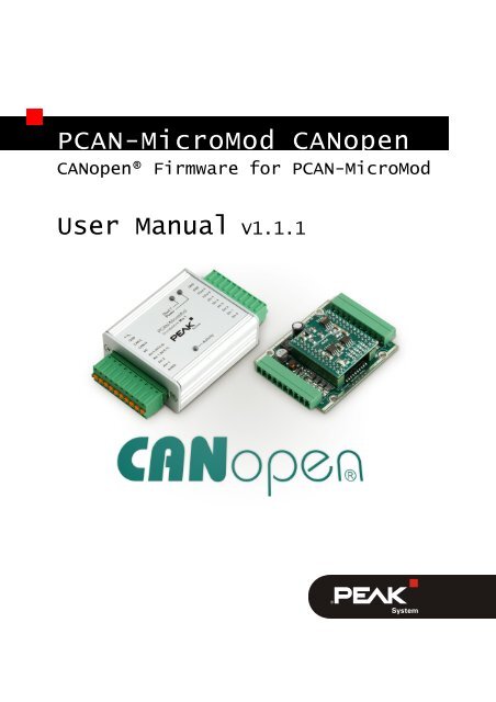
<strong>PCAN</strong>-<strong>MicroMod</strong> <strong>CANopen</strong><br />
<strong>CANopen</strong>® Firmware for <strong>PCAN</strong>-<strong>MicroMod</strong><br />
<strong>User</strong> <strong>Manual</strong> V1.1.1
<strong>PCAN</strong>-<strong>MicroMod</strong> <strong>CANopen</strong> - <strong>User</strong> <strong>Manual</strong><br />
Products taken into account<br />
Product name Model Part number<br />
<strong>CANopen</strong>® Firmware for <strong>PCAN</strong>-<strong>MicroMod</strong><br />
<strong>CANopen</strong>® and CiA® are registered community trade marks of CAN in Automation<br />
e.V.<br />
All other product names mentioned in this document may be the trademarks or<br />
registered trademarks of their respective companies. They are not explicitly marked<br />
by “” and “®”.<br />
© 2012 <strong>PEAK</strong>-<strong>System</strong> Technik GmbH<br />
<strong>PEAK</strong>-<strong>System</strong> Technik GmbH<br />
Otto-Roehm-Strasse 69<br />
64293 Darmstadt<br />
Germany<br />
Phone: +49 (0)6151 8173-20<br />
Fax: +49 (0)6151 8173-29<br />
www.peak-system.com<br />
info@peak-system.com<br />
Document version 1.1.1 (2012-02-24)<br />
2
<strong>PCAN</strong>-<strong>MicroMod</strong> <strong>CANopen</strong> - <strong>User</strong> <strong>Manual</strong><br />
Contents<br />
1 Outline and Introduction 5<br />
1.1 About the <strong>CANopen</strong>® Implementation 6<br />
1.2 Scope of Supply 6<br />
1.3 Hardware and Software Requirements 6<br />
1.4 Terminology and Abbreviations 7<br />
2 Product and Firmware Selection 13<br />
2.1 Device Summary 13<br />
2.2 Loading the Firmware into a <strong>MicroMod</strong> 14<br />
2.3 Processing Times and Performance 15<br />
3 Hardware Features 18<br />
3.1 Status and Error LEDs 18<br />
3.2 Boot Mode Selection with Solder Bridges 19<br />
3.3 Assignment of Bit Rate and Node ID 19<br />
3.4 Status Info on Serial Port 20<br />
4 <strong>CANopen</strong>® Implementation 22<br />
4.1 Product Identification 23<br />
4.2 Default Connection Set 24<br />
4.3 Default PDO Mapping 25<br />
4.4 Input Processing 26<br />
4.5 Output Processing 28<br />
4.6 Heartbeat Production and Consumption 29<br />
4.7 Storing Parameters 30<br />
3
<strong>PCAN</strong>-<strong>MicroMod</strong> <strong>CANopen</strong> - <strong>User</strong> <strong>Manual</strong><br />
Appendix A Object Dictionary Reference 32<br />
A.1 Overview 32<br />
A.2 Communication Profile Entries 34<br />
A.3 Device Profile Entries 50<br />
4
<strong>PCAN</strong>-<strong>MicroMod</strong> <strong>CANopen</strong> - <strong>User</strong> <strong>Manual</strong><br />
1 Outline and Introduction<br />
<strong>CANopen</strong>® is a popular industrial communication standard used in<br />
many embedded networking applications such as mobile machinery,<br />
industrial automation, medical equipment and many more.<br />
The standards including all the device and application profiles are<br />
maintained by the CiA, the CAN in Automation <strong>User</strong>’s and Manufacturer’s<br />
Group.<br />
One of the main reasons for the popularity of <strong>CANopen</strong> is its flexibility<br />
towards customization. <strong>CANopen</strong> provides a set of standardized<br />
communication functions of which only a little percentage is<br />
mandatory. When designing a network for a specific application,<br />
engineers and designers can choose which functions are needed<br />
and can even add custom functionality where required.<br />
Nevertheless, the standardized <strong>CANopen</strong> device and application<br />
profiles available still enable off-the-shelf, plug-and-play usage of<br />
<strong>CANopen</strong> devices. <strong>System</strong> designers that need to add standardized<br />
sensors or actuators such as generic I/Os, encoders, drives, and<br />
motors can choose from a wide variety of products from numerous<br />
manufacturers.<br />
Although this user manual explains all the <strong>CANopen</strong> features implemented<br />
by the software provided, it still assumes that the reader<br />
has some basic knowledge about Controller Area Network (CAN)<br />
and <strong>CANopen</strong>. If in doubt, the CAN and <strong>CANopen</strong> specifications or<br />
books like “Embedded Networking with CAN and <strong>CANopen</strong>”<br />
(www.canopenbook.com) should be consulted.<br />
Note: This user manual only contains information about the<br />
<strong>CANopen</strong> firmware to be used with a <strong>PCAN</strong>-<strong>MicroMod</strong>. For<br />
detailed information about the hardware please refer to the<br />
extra manual.<br />
5
<strong>PCAN</strong>-<strong>MicroMod</strong> <strong>CANopen</strong> - <strong>User</strong> <strong>Manual</strong><br />
1.1 About the <strong>CANopen</strong>® Implementation<br />
The <strong>PCAN</strong>-<strong>MicroMod</strong> I/O modules fall into the category of off-theshelf<br />
<strong>CANopen</strong> generic I/O devices. The <strong>CANopen</strong> software package<br />
for these modules implements the following CiA standards:<br />
CiA® 301 “<strong>CANopen</strong> Application Layer and Communication<br />
Profile” version 4.02<br />
CiA® 401 “<strong>CANopen</strong> Device Profile for Generic I/O Modules”<br />
version 2.1<br />
By loading the appropriate firmware into the modules, they can be<br />
directly used as standardized <strong>CANopen</strong> generic I/O modules.<br />
The EDS files (Electronic Data Sheet) provided along with the firmware<br />
were tested with their corresponding module for <strong>CANopen</strong><br />
conformance using the official <strong>CANopen</strong> conformance tests.<br />
1.2 Scope of Supply<br />
The <strong>CANopen</strong> firmware package is license free for all users of<br />
<strong>PCAN</strong>-<strong>MicroMod</strong> and can be downloaded as part of the <strong>PCAN</strong>-<br />
<strong>MicroMod</strong> package from www.peak-system.com.<br />
The ZIP file available online contains the latest version of the<br />
firmware (Fujitsu hex file format), the EDS files, and the user<br />
manual in PDF format. Furthermore, a flash tool for loading the<br />
firmware into a <strong>MicroMod</strong> is included.<br />
1.3 Hardware and Software Requirements<br />
The <strong>CANopen</strong> firmware is loaded into a <strong>PCAN</strong>-<strong>MicroMod</strong> using the<br />
<strong>PCAN</strong>-<strong>MicroMod</strong> Evaluation Board. With the flash programming<br />
utility, the hex files provided can be programmed.<br />
6
<strong>PCAN</strong>-<strong>MicroMod</strong> <strong>CANopen</strong> - <strong>User</strong> <strong>Manual</strong><br />
In order to configure a <strong>MicroMod</strong> a generic <strong>CANopen</strong> Configuration<br />
Tool with access to the CAN bus is required. We recommend the<br />
software package <strong>PCAN</strong>open Magic Pro (www.canopenmagic.com)<br />
with a <strong>PCAN</strong>-USB interface.<br />
1.4 Terminology and Abbreviations<br />
The following <strong>CANopen</strong> terms and abbreviations are used in this<br />
manual without further explanation. Please refer to the <strong>CANopen</strong><br />
standards CiA® 301, CiA® 302, and CiA® 401 or books like<br />
“Embedded Networking with CAN and <strong>CANopen</strong>” for further<br />
explanation.<br />
[xxxxh,yyh]<br />
This syntax is used to indicate an Object Dictionary entry using<br />
hexadecimal values. The first number ‘xxxx’ represents the Index<br />
and ‘yy’ the Subindex.<br />
Bit Rate<br />
The default bit rates supported by many <strong>CANopen</strong> nodes are<br />
1 Mbit/s, 800 kbit/s, 500 kbit/s, 250 kbit/s, 125 kbit/s, and 50 kbit/s.<br />
The bit rate can be changed using the [1F50h,03h] Object Dictionary<br />
entry.<br />
Boot-up Message<br />
After a reset, a <strong>CANopen</strong> node transmits its boot-up message. The<br />
message (CAN) identifier used is 700h plus the node’s Node ID<br />
number. The boot-up message contains one data byte which is zero.<br />
<strong>CANopen</strong> Manager<br />
In a <strong>CANopen</strong> network the optional <strong>CANopen</strong> Manager typically<br />
includes a NMT Master and a Configuration Manager. The NMT<br />
Master is responsible for generating the NMT Master Message and<br />
starting or stopping the network. The Configuration Manager keeps<br />
7
<strong>PCAN</strong>-<strong>MicroMod</strong> <strong>CANopen</strong> - <strong>User</strong> <strong>Manual</strong><br />
track of all nodes connected and ensures that the connected nodes<br />
are configured correctly.<br />
Change-of-state (COS)<br />
Generic I/O modules typically monitor their inputs for changes.<br />
<strong>CANopen</strong> nodes can be configured to only transmit this input data,<br />
if a change was detected.<br />
Connection Object Identifier, COB-ID<br />
The COB-ID specifies the CAN message details used for a specific<br />
connection. These include a (CAN) Message Identifier and typically<br />
an enable/disable bit.<br />
Default Connection Set<br />
The default connection set determines which (CAN) Message<br />
Identifier is used for which purpose in a <strong>CANopen</strong> network.<br />
Typically (CAN) Message Identifiers are assigned using a base<br />
identifier (such as 180h for TPDO1) and adding the Node ID to that<br />
base identifier.<br />
Emergency, EMCY<br />
<strong>CANopen</strong> emergency messages have a default (CAN) Message<br />
Identifier of 80h plus the Node ID of the node generating the<br />
emergency. Emergency messages contain a <strong>CANopen</strong> specified<br />
emergency code, the error register [1001h,00h] and a manufacturer<br />
specific emergency code.<br />
Event Time<br />
For TPDOs the Event Time specifies the periodic time at which<br />
TPDOs get transmitted. The Event Time is specified in multiples of<br />
milliseconds and typically only used if the Transmission Type is set<br />
to 255d/FFh.<br />
Heartbeat Producer and Consumer<br />
In <strong>CANopen</strong> the recommended function to monitor the health of<br />
network nodes is to use the heartbeat mechanism. Each <strong>CANopen</strong><br />
8
<strong>PCAN</strong>-<strong>MicroMod</strong> <strong>CANopen</strong> - <strong>User</strong> <strong>Manual</strong><br />
node can individually produce a heartbeat message, using the<br />
(CAN) Message Identifier 0700h plus the node’s Node ID. The<br />
message contains a single byte representing the current NMT state<br />
of the node (like Pre-Operational, Operational, Stopped). The Heartbeat<br />
Producer time [1017h,00h] is specified in multiples of milliseconds.<br />
<strong>CANopen</strong> nodes may have zero, one, or multiple Heartbeat<br />
Consumers [1016h,xxh] that can be configured to monitor heartbeats<br />
from other nodes. If a node looses a heartbeat monitored, it<br />
typically transmits an emergency message and goes back into the<br />
Pre-Operational NMT state.<br />
Inhibit Time<br />
For TPDOs that implement a COS detection, the Inhibit Time is used<br />
to prevent back-to-back transmission of input data that changes frequently.<br />
The Inhibit Time is selected in multiples of 100s of microseconds<br />
and specifies how long a <strong>CANopen</strong> node must wait before it<br />
may transmit a TPDO again. Note that many <strong>CANopen</strong> implementations<br />
do not offer such a high resolution and the Inhibit Time might<br />
get rounded up to milliseconds.<br />
Index<br />
An Object Dictionary entry is selected using a 16-bit Index and an 8bit<br />
Subindex.<br />
Layer Setting Services (LSS)<br />
A <strong>CANopen</strong> standard defining how layer services like bit rate and<br />
Node ID can be changed during operation.<br />
Manager/Master<br />
In <strong>CANopen</strong> there are several Master and Manager services,<br />
typically combined into the ‘<strong>CANopen</strong> Manager’.<br />
Message Identifier<br />
Any communication technology used for <strong>CANopen</strong> (default is CAN –<br />
Controller Area Network) must be able to assign a Message Identifier<br />
to any message transferred. CAN uses the default of an 11-bit<br />
9
<strong>PCAN</strong>-<strong>MicroMod</strong> <strong>CANopen</strong> - <strong>User</strong> <strong>Manual</strong><br />
Message Identifier. The Default Connection Set selects how these<br />
Message Identifiers are used.<br />
Network Management (NMT)<br />
Each <strong>CANopen</strong> node internally implements an NMT Slave state<br />
machine with the major states being Pre-Operational (used to<br />
configure devices), Operational (actively producing and consuming<br />
PDOs) and Stopped (limiting communication to Heartbeats). The<br />
NMT Master Message is used to command nodes to switch their<br />
NMT States.<br />
NMT Master Message<br />
The NMT Master (often integrated into the <strong>CANopen</strong> Manager) uses<br />
the NMT Master Message to switch the NMT State of individual or<br />
all nodes. The (CAN) Message Identifier of the NMT Master<br />
Message is 0 (zero) with 2 data bytes.<br />
Node ID<br />
In any <strong>CANopen</strong> network each <strong>CANopen</strong> node must have a unique<br />
Node ID in the range of 1 to 127. The Node ID can be changed using<br />
the [1F50h,03h] Object Dictionary entry.<br />
Object Dictionary, OD<br />
Each <strong>CANopen</strong> node internally structures its data (configuration and<br />
process data) into an Object Dictionary, similar to a look-up table.<br />
Each entry can be identified by a 16-bit Index and an 8-bit Subindex.<br />
The <strong>CANopen</strong> standards specify which entry is used for which<br />
purpose. A configuration tool or <strong>CANopen</strong> Manager can access the<br />
OD of any node using SDO communication.<br />
PDO Communication Parameters<br />
The PDO communication parameters include COB ID, Transmission<br />
Type, Inhibit Time, and Event Time. They specify the used (CAN)<br />
message identifier and for Transmit PDOs the selected trigger<br />
events.<br />
10
<strong>PCAN</strong>-<strong>MicroMod</strong> <strong>CANopen</strong> - <strong>User</strong> <strong>Manual</strong><br />
PDO Mapping Parameters<br />
The PDO Mapping Parameters select the contents of a PDO. One or<br />
multiple variables from the Object Dictionary can be combined into<br />
a PDO.<br />
Process Data Object, PDO<br />
These (CAN) messages are used for communicating process data.<br />
Receive Process Data Object, RPDO<br />
Each <strong>CANopen</strong> node typically can transmit and receive PDOs. To<br />
better distinguish between the services, the terms RPDOs and<br />
TPDOs are used. Note that a TPDO of one node is a RPDO for all<br />
other nodes that consume this PDO.<br />
Service Data Object, SDO<br />
These (CAN) messages are used for communicating<br />
service/configuration data.<br />
Subindex<br />
An Object Dictionary entry is selected using a 16-bit Index and an 8bit<br />
Subindex.<br />
Synchronized Communication<br />
In synchronized communication mode (one of the Transmission<br />
Types supported by <strong>CANopen</strong>), RPDO data received is not immediately<br />
applied to the outputs; it is only applied after the SYNC message<br />
was received. Synchronized TPDO data gets transmitted right<br />
after the SYNC message is received.<br />
Transmission Type<br />
For each PDO the Transmission Type can be selected as it is one of<br />
the PDO Communication Parameters. The default Transmission<br />
Type is 255/FFh selecting the communication specific for the Device<br />
Profile. In the case of CiA® 401 Generic I/O this means that both<br />
Event Time and Inhibit Time are used.<br />
11
<strong>PCAN</strong>-<strong>MicroMod</strong> <strong>CANopen</strong> - <strong>User</strong> <strong>Manual</strong><br />
Transmit Process Data Object, TPDO<br />
Each <strong>CANopen</strong> node typically can transmit and receive PDOs. To<br />
better distinguish between the services, the terms RPDOs and<br />
TPDOs are used. Note that a TPDO of one node is a RPDO for all<br />
other nodes that consume this PDO.<br />
12
<strong>PCAN</strong>-<strong>MicroMod</strong> <strong>CANopen</strong> - <strong>User</strong> <strong>Manual</strong><br />
2 Product and Firmware<br />
Selection<br />
All <strong>CANopen</strong> firmware versions for <strong>PCAN</strong>-<strong>MicroMod</strong> use the same<br />
code basis and thus have similar features. The main difference is<br />
that the number of I/O channels made available matches the hardware<br />
layout of the various motherboards.<br />
2.1 Device Summary<br />
The generic firmware version (device 0) is a superset, as it implements<br />
the maximum number of I/O channels supported. This version<br />
is intended for users that embed a <strong>MicroMod</strong> into their own<br />
customized hardware.<br />
All other firmware versions provided implement a specific subset<br />
enabling a limited number of I/O channels.<br />
The following table lists the number of channels available with each<br />
device. The header indicates the resolution for each I/O channel<br />
(exceptions apply for Analog 2).<br />
Device DI (1 bit) DO (1 bit) AI (10 bits) AO (8 bits)<br />
0 <strong>MicroMod</strong> (custom) 8 7<br />
8 4<br />
Evaluation Board<br />
(see also<br />
Mix 3<br />
note below)<br />
1 Digital 1 8 4 0 1<br />
2 Digital 2 8 4 0 1<br />
3 Analog 1 8 (shared AI) 0 8 4<br />
4 Mix 1 6 0 4 2<br />
5 Mix 2 2 1 5 2<br />
6 Analog 2 0 0 8 (16 bits) 4 (12 bits)<br />
13
<strong>PCAN</strong>-<strong>MicroMod</strong> <strong>CANopen</strong> - <strong>User</strong> <strong>Manual</strong><br />
Resolution (bits) Value range hex Value range dec<br />
8 0 - 00FFh 0 - 255<br />
10 0 - 03FFh 0 - 1023<br />
12 0 - 0FFFh 0 - 4095<br />
16 signed 0 - FFFFh -32768 - +32767<br />
Note for Device 0: The digital outputs of the <strong>PCAN</strong>-<strong>MicroMod</strong><br />
Evaluation Board and the motherboard Mix 3 behave differently<br />
regarding the Low and High states. Please refer to the user<br />
manual of the respective motherboard.<br />
2.2 Loading the Firmware into a <strong>MicroMod</strong><br />
The hex files provided can be loaded into a <strong>MicroMod</strong> using the<br />
<strong>PCAN</strong>-<strong>MicroMod</strong> Evaluation Board and the Fujitsu Flash 16 programming<br />
utility (part of the <strong>PCAN</strong>-<strong>MicroMod</strong> software package).<br />
Follow these steps to upload the firmware:<br />
1. Make sure that the power plug of the Evaluation Board is<br />
disconnected.<br />
2. Plug the <strong>MicroMod</strong> to be programmed onto the Evaluation<br />
Board.<br />
3. On the Evaluation Board set the programming jumper S5 to<br />
“Prog” (2-3) to activate the on-chip boot loader.<br />
4. Make sure that the DIP switches 1 and 2 are in the ‘off’<br />
position.<br />
5. Connect the serial connector “RS232” to the COM port of<br />
the PC.<br />
6. Start the Fujitsu Flash 16 programming utility (flash.exe).<br />
14
<strong>PCAN</strong>-<strong>MicroMod</strong> <strong>CANopen</strong> - <strong>User</strong> <strong>Manual</strong><br />
7. Re-apply power to the Evaluation Board and press the reset<br />
button to ensure the processor goes properly into the boot<br />
mode.<br />
8. Make the following settings in the Fujitsu Flash 16 utility:<br />
Target Microcontroller: MB90F497/G<br />
Crystal Frequency: 4 MHz<br />
Hex File: one of the hex files implementing <strong>CANopen</strong><br />
9. Press the button “Full Operation”.<br />
The Flash 16 utility converts the hex file, transfers it to<br />
<strong>MicroMod</strong> and programs it into the flash memory.<br />
10. Once the process is completed, you can power down the<br />
Evaluation Board, remove the <strong>MicroMod</strong>, and insert it into<br />
appropriate <strong>CANopen</strong> target hardware.<br />
2.3 Processing Times and Performance<br />
The <strong>CANopen</strong> firmware was optimized to provide the best possible<br />
performance. Nevertheless, it should be noted that in any <strong>CANopen</strong><br />
based I/O system the flexible configuration potentially allows configuring<br />
a module in such a way that its performance can vary<br />
considerably.<br />
As a result all timings given here are not ‘true’ worst-case timings.<br />
For example, they can be delayed by higher-priority CAN activity,<br />
such as an NMT Master message.<br />
On an 1-Mbit/s CAN network, Event, Inhibit or synchronization cycle<br />
times of down to 5 milliseconds may be used with the <strong>MicroMod</strong><br />
without any performance penalty. Even shorter times are possible<br />
but their accuracy depends on the overall PDO configuration (how<br />
many PDOs need to be that fast and how long are they).<br />
15
<strong>PCAN</strong>-<strong>MicroMod</strong> <strong>CANopen</strong> - <strong>User</strong> <strong>Manual</strong><br />
2.3.1 Digital I/O Performance<br />
Processing of all digital I/Os happens on a 500-microsecond timer<br />
basis. For best performance, digital I/Os should always be mapped<br />
into the first RPDO/TPDO as that is processed with a higher priority.<br />
Digital outputs get applied to the outputs within one millisecond<br />
after the triggering message was received. This is either the RPDO1<br />
itself or the SYNC message if synchronized communication is used.<br />
With the change-of-state (COS) detection a change in the digital inputs<br />
is typically recognized within one millisecond and immediately<br />
triggers the transmission of TPDO if COS communication is used.<br />
However, process data received is processed at a higher priority,<br />
potentially delaying the COS detection.<br />
2.3.2 Analog I/O Performance<br />
Processing of all analog I/Os happens on a 1-millisecond timer<br />
basis. Each millisecond one analog input channel and one analog<br />
output channel are updated. As a result, the overall delay in analog<br />
data processing depends on the number of analog channels used.<br />
With a system using 8 analog inputs each input is updated every 8<br />
milliseconds. The COS and minimal delta detection typically requires<br />
another millisecond to execute and detect potential changes.<br />
If a system has 4 analog outputs, then the delay in applying new<br />
received values to the outputs can be up to 4 milliseconds.<br />
16
<strong>PCAN</strong>-<strong>MicroMod</strong> <strong>CANopen</strong> - <strong>User</strong> <strong>Manual</strong><br />
2.3.3 Background Task and Change Of State<br />
Detection<br />
Processing of change-of-state and analog input delta detection,<br />
heartbeat production and consumption and SDO request processing<br />
is all handled in the main background task. As both CAN Receive<br />
Interrupt and the 500-microsecond Timer Interrupt have a higher<br />
priority, the background task can get interrupted and delayed at any<br />
time.<br />
The <strong>PEAK</strong> Status Register [1002h,00h] in the Object Dictionary contains<br />
the current average execution time of a single background<br />
loop. In operational mode, this number typically varies from 300 to<br />
600 microseconds.<br />
17
<strong>PCAN</strong>-<strong>MicroMod</strong> <strong>CANopen</strong> - <strong>User</strong> <strong>Manual</strong><br />
3 Hardware Features<br />
This chapter summarizes the most important <strong>PCAN</strong>-<strong>MicroMod</strong> hardware<br />
features as far as the <strong>CANopen</strong> implementation is concerned.<br />
For further hardware details like pin assignment and I/O characteristics,<br />
please refer to the <strong>PCAN</strong>-<strong>MicroMod</strong> user manual and those for<br />
the <strong>PCAN</strong>-<strong>MicroMod</strong> motherboards.<br />
3.1 Status and Error LEDs<br />
<strong>CANopen</strong> supports two LED indicators as specified by document<br />
DR303 “Indicator Specification”. Concerning the <strong>CANopen</strong> Firmware<br />
the RUN LED is located directly on the <strong>MicroMod</strong>. The ERR<br />
LED is related to DO7.<br />
3.1.1 RUN LED<br />
The RUN LED shows one of the following patterns:<br />
LED Status Description<br />
On Node is in NMT state “Operational”<br />
Blinking Node is in NMT state “Pre-operational”<br />
Single Flash Node is in NMT state “Stopped”<br />
3.1.2 ERR LED<br />
The ERR LED shows one of the following patterns:<br />
LED Status Description<br />
Off No Error<br />
On Node is not yet initialized after reset or a fatal error occurred<br />
Double Flash Heartbeat lost<br />
18
<strong>PCAN</strong>-<strong>MicroMod</strong> <strong>CANopen</strong> - <strong>User</strong> <strong>Manual</strong><br />
3.2 Boot Mode Selection with Solder<br />
Bridges<br />
<strong>PCAN</strong>-<strong>MicroMod</strong> features a total of 5 solder bridges. The <strong>CANopen</strong><br />
implementations currently only use the solder bridge ‘4’ as a boot<br />
mode indicator. If solder bridge ‘4’ is closed, after reset, <strong>PCAN</strong>-<br />
<strong>MicroMod</strong> starts in a default boot mode using a CAN bit rate of<br />
125 kbit/s and the <strong>CANopen</strong> node ID 40h/64d.<br />
A “blinking” LED blinks with a period of 200 milliseconds.<br />
A “single flash” LED is on for 200 milliseconds and then off for<br />
1 second.<br />
3.3 Assignment of Bit Rate and Node ID<br />
The CAN bit rate and <strong>CANopen</strong> node ID used cannot be changed by<br />
hardware. They can be changed by writing specific values to an<br />
Object Dictionary entry.<br />
Using a <strong>CANopen</strong> configuration tool (such as <strong>CANopen</strong> Magic),<br />
writes to the Object Dictionary entry [1F50h,03h] can change the bit<br />
rate and node ID.<br />
Writing the 4-byte ASCII string “BPSx” changes the bit rate. ‘x’ must<br />
be replaced with one of the following digits (LSS compatible<br />
values):<br />
Value Bit rate<br />
0 1 Mbit/s<br />
1 800 kbit/s<br />
2 500 kbit/s<br />
3 250 kbit/s<br />
4 125 kbit/s<br />
6 50 kbit/s<br />
19
<strong>PCAN</strong>-<strong>MicroMod</strong> <strong>CANopen</strong> - <strong>User</strong> <strong>Manual</strong><br />
Other bit rates are not supported.<br />
Writing the 4-byte ASCII string “NIxy” changes the node ID. ‘xy’<br />
must be replaced by a 2-digit hexadecimal number specifying the<br />
new node ID, which must be in the range of 01h to 7Fh.<br />
Note: The new settings will only be activated after the next<br />
reset of the <strong>MicroMod</strong>.<br />
Figure 1: Example for sending the 'NI' command to a node<br />
using <strong>PCAN</strong>open Magic Pro<br />
3.4 Status Info on Serial Port<br />
If a <strong>MicroMod</strong> is used in hardware with serial line drivers (such as<br />
the <strong>PCAN</strong>-<strong>MicroMod</strong> Evaluation Board), then some basic status info<br />
can be displayed on a terminal. The communication settings are:<br />
19200 bit/s, 8 bits, 1 stop bit, no parity.<br />
20
<strong>PCAN</strong>-<strong>MicroMod</strong> <strong>CANopen</strong> - <strong>User</strong> <strong>Manual</strong><br />
Information is only sent during initialization and in case of errors.<br />
Information displayed on the terminal includes the CAN bit rate, the<br />
<strong>CANopen</strong> node ID and the number of input and output channels<br />
used.<br />
In case of a fatal error, an internal error number is displayed.<br />
The following is a sample output:<br />
<strong>PEAK</strong> <strong>MicroMod</strong> <strong>CANopen</strong>IA V1.01 Rev.204<br />
J0-J4: 0<br />
Regular Operation as <strong>MicroMod</strong>: 125kbps, node ID 32<br />
Number of I/O: DI 1, DO 1, AI 8, AO 4<br />
Initialization completed!<br />
21
<strong>PCAN</strong>-<strong>MicroMod</strong> <strong>CANopen</strong> - <strong>User</strong> <strong>Manual</strong><br />
4 <strong>CANopen</strong>® Implementation<br />
The implementation features the major <strong>CANopen</strong> services as standardized<br />
in the following CiA documents:<br />
CiA® 301 “<strong>CANopen</strong> Application Layer and Communication<br />
Profile” version 4.02<br />
CiA® 401 “<strong>CANopen</strong> Device Profile for Generic I/O Modules”<br />
version 2.1<br />
In summary, these services are:<br />
One SDO server giving <strong>CANopen</strong> Managers and configuration<br />
tools access to the internal Object Dictionary (OD)<br />
Heartbeat Producer functionality allowing the devices to<br />
produce their individual heartbeat messages at a configurable<br />
rate<br />
Heartbeat Consumer functionality with up to three channels<br />
allowing the monitoring of up to 3 heartbeats<br />
Although not recommended to be used, the Node Guarding<br />
functionality is still implemented in order to be compatible with<br />
legacy devices<br />
Emergency Producer to inform other nodes over major error or<br />
other emergency situations<br />
Re-configuration of Node ID and bit rate during operation<br />
Storage of configuration parameters in non-volatile memory<br />
4 Receive Process Data Objects (RPDO) with dynamic<br />
communication and mapping parameters – RPDO configuration<br />
including CAN message ID used and contents mapped to the<br />
RPDO can be changed during operation<br />
22
<strong>PCAN</strong>-<strong>MicroMod</strong> <strong>CANopen</strong> - <strong>User</strong> <strong>Manual</strong><br />
4 Transmit Process Data Objects (TPDO) with dynamic<br />
communication and mapping parameters – TPDO configuration<br />
including CAN message ID used, message trigger mechanisms<br />
and contents mapped to the TPDO can be changed during<br />
operation<br />
Up to 8 digital input channels with configurable polarity<br />
inversion<br />
Up to 7 digital output channels with configurable polarity<br />
inversion and default output values for error situations<br />
Up to 8 analog input channels with configurable minimal<br />
difference (delta) detection<br />
Up to 4 analog output channels with individual default output<br />
values for error situation<br />
4.1 Product Identification<br />
There are several Object Dictionary (OD) entries implemented that<br />
can be used to identify the <strong>PCAN</strong>-<strong>MicroMod</strong> and the specific<br />
<strong>CANopen</strong> firmware used:<br />
[1000h,00h] Device Type<br />
32-bit device type info, see table below<br />
[1008h,00h] Manufacturer Device Name<br />
4-byte ASCII string, see table below<br />
[1009h,00h] Manufacturer Hardware Version<br />
4-byte ASCII string with the hardware version number<br />
[100Ah,00h] Manufacturer Software Version<br />
4-byte ASCII string with the firmware revision number<br />
[1018h,01h] <strong>CANopen</strong> vendor ID<br />
32-bit vendor ID of <strong>PEAK</strong>: 00000175h<br />
23
<strong>PCAN</strong>-<strong>MicroMod</strong> <strong>CANopen</strong> - <strong>User</strong> <strong>Manual</strong><br />
[1018h,02h] Product Code<br />
32-bit product code, see table below<br />
[1018h,03h] Revision Number<br />
32-bit revision number<br />
Device Device Type<br />
OD [1000h,00h]<br />
0 <strong>MicroMod</strong> (custom)<br />
Evaluation Board<br />
Mix 3<br />
24<br />
Device Name<br />
[1008h,00h]<br />
Product ID<br />
[1018h,0]<br />
000F0191h “PCO0” 00100000h<br />
1 Digital 1 000B0191h “PCO1” 00100001h<br />
2 Digital 2 000B0191h “PCO2” 00100002h<br />
3 Analog 1 000D0191h “PCO3” 00100003h<br />
4 Mix 1 000D0191h “PCO4” 00100004h<br />
5 Mix 2 000F0191h “PCO5” 00100005h<br />
6 Analog 2 000C0191h “PCO6” 00100006h<br />
4.2 Default Connection Set<br />
The <strong>CANopen</strong> implementations use the Default Connection Set.<br />
This means the following CAN Message Identifiers are used, unless<br />
the devices are re-configured.<br />
CAN Message ID Direction Default Usage<br />
000h Receive NMT Master Message<br />
080h Receive SYNC Message<br />
080h + Node ID Transmit Emergency Message<br />
180h + Node ID Transmit TPDO 1<br />
200h + Node ID Receive RPDO 1<br />
280h + Node ID Transmit TPDO 2<br />
300h + Node ID Receive RPDO 2<br />
380h + Node ID Transmit TPDO 3<br />
400h + Node ID Receive RPDO 3<br />
480h + Node ID Transmit TPDO 4
<strong>PCAN</strong>-<strong>MicroMod</strong> <strong>CANopen</strong> - <strong>User</strong> <strong>Manual</strong><br />
CAN Message ID Direction Default Usage<br />
500h + Node ID Receive RPDO 4<br />
580h + Node ID Transmit SDO Response<br />
600h + Node ID Receive SDO Request<br />
700h + Node ID Transmit Boot-up, Heartbeat<br />
Per default unused PDOs are disabled.<br />
4.3 Default PDO Mapping<br />
The default PDO mapping used is that of the <strong>CANopen</strong> Device<br />
Profile CIA® 401 for generic I/O. A maximum of four variables are<br />
mapped to each PDO. The following table illustrates the mapping<br />
used by the <strong>PCAN</strong>-<strong>MicroMod</strong> device zero (stand-alone module). The<br />
other device types only have those variables mapped that are<br />
implemented on these devices.<br />
PDO No. of<br />
Entries<br />
Entry 1 Entry 2 Entry 3 Entry 4<br />
RPDO1 1 DO (1-7) empty empty empty<br />
RPDO2 4 AO 1 AO 2 AO 3 AO 4<br />
TPDO1 1 DI (1-8) empty empty empty<br />
TPDO2 4 AI 1 AI 2 AI 3 AI 4<br />
TPDO3 4 AI 5 AI 6 AI 7 AI 8<br />
The PDO parameters can easily be changed with <strong>CANopen</strong><br />
configuration tools such as <strong>PCAN</strong>open Magic Pro.<br />
25
<strong>PCAN</strong>-<strong>MicroMod</strong> <strong>CANopen</strong> - <strong>User</strong> <strong>Manual</strong><br />
Figure 2: <strong>PCAN</strong>open Magic Pro displaying the PDO parameters with the possibility to<br />
edit each entry directly<br />
4.4 Input Processing<br />
Digital input data is XORed with the polarity settings [6002h] before<br />
getting stored in [6000h]. The analog input data goes directly into<br />
the array at [6401h].<br />
Using SDO requests sent to the device, all input data can be read at<br />
any time by a configuration tool or <strong>CANopen</strong> manager.<br />
26
<strong>PCAN</strong>-<strong>MicroMod</strong> <strong>CANopen</strong> - <strong>User</strong> <strong>Manual</strong><br />
Figure 3: Input data processed by the <strong>CANopen</strong> firmware<br />
Depending on the TPDO Mapping Parameters [1A0xh], the input<br />
data is included in one or multiple TPDOs. Depending on the TPDO<br />
Communication Parameters [180xh] the input data gets transmitted<br />
if a transmit trigger is activated. For analog inputs, the change-ofstate<br />
detection includes a delta detection: if the Analog Input<br />
Interrupt Enable [6423h] is set, then the array Analog Input Value<br />
Difference [6426h] specifies for each channel the minimum<br />
difference that a new value must have in comparison to the last<br />
transmitted value to trigger a COS event.<br />
27
<strong>PCAN</strong>-<strong>MicroMod</strong> <strong>CANopen</strong> - <strong>User</strong> <strong>Manual</strong><br />
4.5 Output Processing<br />
Data received in a RPDO is copied to its destination in the Object<br />
Dictionary, depending on the RPDO Mapping Parameters [160xh].<br />
The destination is the array at [6200h] for digital outputs and the<br />
array at [6411h] for analog outputs. These entries can also be<br />
written to by any <strong>CANopen</strong> configuration tool or <strong>CANopen</strong> manager<br />
using SDO requests.<br />
Figure 4: Output data processed by the <strong>CANopen</strong> firmware<br />
Depending on the RPDO Communication Parameters [140xh] the<br />
output data received by RPDO is either applied immediately or upon<br />
reception of the next SYNC signal if synchronized communication is<br />
used.<br />
Digital output data is XORed with the Polarity Digital Output value<br />
at [6202h] before being applied to the output.<br />
When an output channel is marked ‘1’ the Digital Output Error Mode<br />
[6206h] array or the Analog Output Error Mode [6443h] array, then<br />
default values get applied to the outputs whenever the node leaves<br />
28
<strong>PCAN</strong>-<strong>MicroMod</strong> <strong>CANopen</strong> - <strong>User</strong> <strong>Manual</strong><br />
the operational state. The default outputs for each channel are<br />
stored in the arrays Digital Output Error Value [6207h] and Analog<br />
Output Error Value [6444h].<br />
4.6 Heartbeat Production and Consumption<br />
The recommended method to monitor the health of each <strong>CANopen</strong><br />
node is using the heartbeat protocol. Each <strong>CANopen</strong> node produces<br />
its own heartbeat. The heartbeat producer time [1017h,00h] can be<br />
set with a configuration tool. The time is specified in milliseconds.<br />
In addition, the firmware implements 3 heartbeat consumer<br />
channels allowing the <strong>MicroMod</strong> to monitor up to 3 heartbeats from<br />
other nodes. Each heartbeat consumer entry at [1016h,01h-03h] is a<br />
Unsigned32 value, where the consumer time (timeout) is stored in<br />
bits 0-15, and bits 16-22 hold the node ID of the node monitored.<br />
The heartbeat consumer time must be bigger than the producer<br />
time of the node monitored. Otherwise a “heartbeat lost event” will<br />
occur almost immediately after monitoring begins. A recommended<br />
approach is to make the consumer time 1.5 times bigger than the<br />
producer time.<br />
Upon loosing a heartbeat, a <strong>PCAN</strong>-<strong>MicroMod</strong> device transmits an<br />
emergency message and switches itself into the pre-operational<br />
mode. When the default error output mode is activated, the default<br />
outputs get applied.<br />
29
<strong>PCAN</strong>-<strong>MicroMod</strong> <strong>CANopen</strong> - <strong>User</strong> <strong>Manual</strong><br />
4.7 Storing Parameters<br />
All configurable parameters of the <strong>CANopen</strong> implementation can be<br />
stored in non-volatile memory and be automatically activated after<br />
the next reset. This way complex configuration does not need to be<br />
made over and over again after every reset of the device.<br />
To save the current configuration into non-volatile memory, the 4byte<br />
string “save” needs to be written to OD entry Store Parameters<br />
[1010h,01h].<br />
It should be noted that saving the current configuration into nonvolatile<br />
memory takes longer than other SDO accesses. On some<br />
<strong>CANopen</strong> configuration tools it might be necessary to lengthen the<br />
timeout for SDO requests.<br />
The manufacturer default configuration can be restored by writing<br />
the 4-byte string “load” to the OD entry Restore Parameters<br />
[1011h,01h]. The default settings become active after the next reset.<br />
Figure 5: Settings for storing parameters<br />
30
<strong>PCAN</strong>-<strong>MicroMod</strong> <strong>CANopen</strong> - <strong>User</strong> <strong>Manual</strong><br />
The OD entries at Verify Configuration [1020h] can be used to save<br />
the configuration date and time into non-volatile memory. This<br />
allows <strong>CANopen</strong> managers to verify when the device was<br />
configured for the last time.<br />
31
<strong>PCAN</strong>-<strong>MicroMod</strong> <strong>CANopen</strong> - <strong>User</strong> <strong>Manual</strong><br />
Appendix A Object Dictionary<br />
Reference<br />
A.1 Overview<br />
The firmware implements a <strong>CANopen</strong> Object Dictionary (OD). The<br />
specific OD implementation for each module is specified by the<br />
corresponding Electronic Data Sheet (EDS). OD entries belonging to<br />
I/O channels are only implemented if the matching device has these<br />
channels available.<br />
The following table gives an overview of all OD entries<br />
implemented.<br />
Index Name Type Access<br />
1000h Device Type Unsigned32 Read Only<br />
1001h Error Register Unsigned8 Read Only<br />
1002h <strong>PEAK</strong> Status Register Unsigned32 Read Only<br />
1005h SYNC COB ID Unsigned32 Read/Write<br />
1008h Manufacturer Device Name Visible_String Read Only<br />
1009h Manufacturer Hardware Version Visible_String Read Only<br />
100Ah Manufacturer Software Version Visible_String Read Only<br />
100Ch Guard Time Unsigned16 Read/Write<br />
100Dh Life Time Factor Unsigned8 Read/Write<br />
1010h Store Parameters Unsigned32 Read/Write<br />
1011h Restore Default Parameters Unsigned32 Read/Write<br />
1016h Consumer Heartbeat Time Array of Unsigned32 Read/Write<br />
1017h Producer Heartbeat Time Unsigned16 Read/Write<br />
1018h Identity Identity Record (0023h) Read Only<br />
1020h Verify Configuration Unsigned32 Read/Write<br />
1400h 1st Receive PDO Parameter PDO Communication<br />
Parameter Record<br />
Read/Write<br />
32
<strong>PCAN</strong>-<strong>MicroMod</strong> <strong>CANopen</strong> - <strong>User</strong> <strong>Manual</strong><br />
Index Name Type Access<br />
1401h 2nd Receive PDO Parameter PDO Communication<br />
Parameter Record<br />
1402h 3rd Receive PDO Parameter PDO Communication<br />
Parameter Record<br />
1403h 4th Receive PDO Parameter PDO Communication<br />
Parameter Record<br />
1600h 1st Receive PDO Mapping PDO Mapping<br />
Parameter Record<br />
1601h 2nd Receive PDO Mapping PDO Mapping<br />
Parameter Record<br />
1602h 3rd Receive PDO Mapping PDO Mapping<br />
Parameter Record<br />
1603h 4th Receive PDO Mapping PDO Mapping<br />
Parameter Record<br />
1800h 1st Transmit PDO Parameter PDO Communication<br />
Parameter Record<br />
1801h 2nd Transmit PDO Parameter PDO Communication<br />
Parameter Record<br />
1802h 3rd Transmit PDO Parameter PDO Communication<br />
Parameter Record<br />
1803h 4th Transmit PDO Parameter PDO Communication<br />
Parameter Record<br />
1A00h 1st Transmit PDO Mapping PDO Mapping<br />
Parameter Record<br />
1A01h 2nd Transmit PDO Mapping PDO Mapping<br />
Parameter Record<br />
1A02h 3rd Transmit PDO Mapping PDO Mapping<br />
Parameter Record<br />
1A03h 4th Transmit PDO Mapping PDO Mapping<br />
Parameter Record<br />
33<br />
Read/Write<br />
Read/Write<br />
Read/Write<br />
Read/Write<br />
Read/Write<br />
Read/Write<br />
Read/Write<br />
Read/Write<br />
Read/Write<br />
Read/Write<br />
Read/Write<br />
Read/Write<br />
Read/Write<br />
Read/Write<br />
Read/Write<br />
1F50h Download Program Array of Domain Read/Write<br />
6000h Read Digital Inputs Array of Unsigned8 Read Only<br />
6002h Polarity Digital Input Array of Unsigned8 Read/Write<br />
6200h Write Digital Outputs Array of Unsigned8 Read/Write<br />
6202h Polarity Digital Output Array of Unsigned8 Read/Write<br />
6206h Digital Output Error Mode Array of Unsigned8 Read/Write<br />
6207h Digital Output Error Value Array of Unsigned8 Read/Write
<strong>PCAN</strong>-<strong>MicroMod</strong> <strong>CANopen</strong> - <strong>User</strong> <strong>Manual</strong><br />
Index Name Type Access<br />
6401h Read Analog Inputs Array of Integer16 Read Only<br />
6411h Write Analog Outputs Array of Integer16 Read/Write<br />
6423h Analog Input Interrupt Enable Boolean Read/Write<br />
6426h Analog Input Value Difference Array of Unsigned32 Read/Write<br />
6443h Analog Output Error Mode Array of Unsigned8 Read/Write<br />
6444h Analog Output Error Value Array of Integer32 Read/Write<br />
A.2 Communication Profile Entries<br />
A.2.1 Device Type (1000h)<br />
[1000h,00h], Unsigned32, read only<br />
This entry indicates the number of the device profile used and<br />
provides some additional basic information about which features of<br />
the device profile are used in the node. The entry value is<br />
constructed as follows:<br />
Bit Description<br />
0-15 Device Profile Number (401d/191h)<br />
16 Set, if the device has digital inputs<br />
17 Set, if the device has digital outputs<br />
18 Set, if the device has analog inputs<br />
19 Set, if the device has analog outputs<br />
20-31 Unused, return zero<br />
A.2.2 Error Register (1001h)<br />
[1001h,00h], Unsigned8, read only, may be mapped to<br />
TPDO<br />
The error register value indicates if an error has occurred within the<br />
device. The Error Register is included in byte two of the Emergency<br />
34
<strong>PCAN</strong>-<strong>MicroMod</strong> <strong>CANopen</strong> - <strong>User</strong> <strong>Manual</strong><br />
object, but may also be mapped into PDOs. The bits in the error<br />
register are defined as follows:<br />
Bit Description<br />
0 Generic Error<br />
1 Current (always zero)<br />
2 Voltage (always zero)<br />
3 Temperature (always zero)<br />
4 Communication Error<br />
5 Device Profile Defined Error (always zero)<br />
6 Reserved (always zero)<br />
7 Manufacturer Specific Error (always zero)<br />
A.2.3 <strong>PEAK</strong> Status Register (1002h), MCU Load, and<br />
Performance<br />
[1002h,00h], Unsigned32, read only<br />
Bits 0 through 11 contain an MCU load indicator. Internally the<br />
devices measure the runtime of the main background loop working<br />
on all input and output data. The value returned in these bits is the<br />
average (measuring 10 loops at the time) runtime of a single loop in<br />
microseconds. In operational status this value typically ranges from<br />
400 microseconds to 650 microseconds.<br />
In each loop all digital inputs and outputs are updated and one each<br />
of analog inputs and analog outputs.<br />
If a device has 4 analog outputs, then it takes 4 loops to update all<br />
analog output channels. So if new analog output data was received<br />
via <strong>CANopen</strong> it can take up to four loop executions until all analog<br />
output channels are set to the new value.<br />
35
<strong>PCAN</strong>-<strong>MicroMod</strong> <strong>CANopen</strong> - <strong>User</strong> <strong>Manual</strong><br />
A.2.4 SYNC COB ID (1005h)<br />
[1005h,00h], Unsigned32, read/write<br />
This entry contains the CAN ID used by the SYNC message along<br />
with a flag to indicate if the node generates the SYNC message or<br />
not. In synchronous PDO communication mode the SYNC message<br />
triggers the TPDOs transmitted.<br />
The 32 bits of the entry are used as follows:<br />
Bit Description<br />
0-10 COB ID for SYNC Object<br />
11-28 Set to 0<br />
29 Set to 0 as only 11-bit CAN IDs are supported<br />
30 Set to 0 as the node does not generate the SYNC Object<br />
31 Set to 0<br />
A.2.5 Manufacturer Device Name (1008h)<br />
[1008h,00h], Visible_String (4 ASCII bytes), read only<br />
Upon reading, this entry returns a 4-byte ASCII string with the<br />
device name. See the table in section 4.1 on page 23 for a list of<br />
names used.<br />
A.2.6 Manufacturer Hardware Version (1009h)<br />
[1009h,00h], Visible_String (4 ASCII bytes), read only<br />
Upon reading, this entry returns a 4-byte ASCII string with the<br />
hardware version number.<br />
A.2.7 Manufacturer Software Version (100Ah)<br />
[1009h,00h], Visible_String (4 ASCII bytes), read only<br />
Upon reading, this entry returns a 4-byte ASCII string with the<br />
software revision number of the <strong>CANopen</strong> firmware.<br />
36
<strong>PCAN</strong>-<strong>MicroMod</strong> <strong>CANopen</strong> - <strong>User</strong> <strong>Manual</strong><br />
A.2.8 Guard Time (100Ch)<br />
[100Ch,00h], Unsigned16, read/write<br />
Note: The CiA recommends not to use node guarding. This<br />
feature has only been implemented to be backwards compatible<br />
to legacy devices.<br />
The guard time specifies how long the period should be in ms<br />
between node guarding requests sent to the device. If the NMT<br />
master implements node guarding, then it should read this entry<br />
and transmit the node guarding requests to the node at the<br />
frequency indicated by the value of this entry.<br />
If a response from the node to a node guarding request is not<br />
transmitted within the node life time, then a node guarding event<br />
occurs, indicating that the node may have possibly stopped<br />
working. If a node guarding request from the NMT Master is not<br />
received within the node life time, then the node knows that the<br />
NMT Master may have possibly stopped working.<br />
The node life time is the guard time multiplied by the life time<br />
factor.<br />
A.2.9 Life Time Factor (100Dh)<br />
[100Dh,00h], Unsigned8, read/write<br />
Note: The CiA recommends not to use node guarding. This<br />
feature has only been implemented to be backwards compatible<br />
to legacy devices.<br />
The life time factor specifies the number of multiples of the guard<br />
time to wait for a response from the node to a node guarding<br />
request.<br />
37
<strong>PCAN</strong>-<strong>MicroMod</strong> <strong>CANopen</strong> - <strong>User</strong> <strong>Manual</strong><br />
If a response from the node to a node guarding request is not<br />
transmitted within the node life time, then a node guarding event<br />
occurs, indicating that the node may have possibly stopped<br />
working. If a node guarding request from the NMT Master is not<br />
received within the node life time, then the node knows that the<br />
NMT Master may have possibly stopped working.<br />
The node life time is the guard time multiplied by the life time<br />
factor.<br />
A.2.10 Store Parameters (1010h)<br />
[1010h,00h], Unsigned8, read only<br />
Returns 1<br />
[1010h,01h] Unsigned32, read/write<br />
The <strong>PCAN</strong>-<strong>MicroMod</strong> devices support Subindex one, store all<br />
parameters to save all configuration data into non-volatile memory.<br />
By writing to the subentries, the node can be instructed to<br />
immediately store all or some of the settings in non-volatile<br />
memory.<br />
By reading the subentries, non-volatile storage capabilities of the<br />
node may be determined.<br />
By writing the value 65766173h (ASCII "save") to [1010h,01h], the<br />
configurable parts of the Object Dictionary are stored in non-volatile<br />
memory.<br />
If a value other than "save" is written, or if the parameter storing<br />
fails for some reason, an SDO abort message is transmitted.<br />
Reading [1010h,01h] returns ‘1’ indicating that the device can save<br />
the parameters by writing to this subentry.<br />
38
<strong>PCAN</strong>-<strong>MicroMod</strong> <strong>CANopen</strong> - <strong>User</strong> <strong>Manual</strong><br />
A.2.11 Restore Default Parameters (1011h)<br />
[1011h,00h], Unsigned8, read only<br />
Returns 1<br />
[1011h,01h] Unsigned32, read/write<br />
The [1011h,00h] entry provides a means to restore the manufacturer<br />
default values for the configurable parameters of the Object<br />
Dictionary. By writing the value 64616F6Ch (ASCII "load") to<br />
[1011h,00h], the configurable parameters will be restored to their<br />
manufacturer default values on the next reset of the node or the<br />
next power cycle.<br />
A.2.12 Consumer Heartbeat Time (1016h)<br />
[1016h,00h], Unsigned8, read only<br />
Returns 3<br />
[1016h,01h], Heartbeat Consumer Channel 1, Unsigned32,<br />
read/write<br />
[1016h,02h], Heartbeat Consumer Channel 2, Unsigned32,<br />
read/write<br />
[1016h,03h], Heartbeat Consumer Channel 3, Unsigned32,<br />
read/write<br />
The devices implement three heartbeat consumer channels and<br />
may listen to the heartbeat messages generated by other nodes on<br />
the network. Each subentry specifies the maximum time to wait for<br />
a heartbeat from a specific node before generating an internal<br />
“Heartbeat Lost” event. The Heartbeat Consumer Time is specified<br />
in milliseconds. Measurement begins after reception of the first<br />
heartbeat message. It does not begin after reception of a boot-up<br />
message.<br />
Each Subindex specifies the Heartbeat Consumer Time for one<br />
<strong>CANopen</strong> node. The value of the entry is constructed as follows:<br />
39
<strong>PCAN</strong>-<strong>MicroMod</strong> <strong>CANopen</strong> - <strong>User</strong> <strong>Manual</strong><br />
Bit Description<br />
0-15 Heartbeat consumer time in milliseconds<br />
16-23 Node ID<br />
24-31 Reserved, set to 0<br />
The Heartbeat Consumer Time of a specific node must be higher<br />
than the Heartbeat Producer Time of the node. It is recommended to<br />
set the consumer time at least 1.5 times higher than the producer<br />
time. The Producer Time can be read from entry 1017h.<br />
Specifying a Heartbeat Consumer Time of zero for a specific Node<br />
ID disables the heartbeat monitoring of that node.<br />
A.2.13 Producer Heartbeat Time (1017h)<br />
[1017h,00h], Unsigned16, read/write<br />
The value of this entry specifies in milliseconds the time between<br />
transmission of heartbeat messages. A value of zero disables<br />
transmission of heartbeat messages by the node.<br />
Because the entry is writeable, the value of the entry may change at<br />
any time.<br />
As the heartbeat production is internally implemented with the<br />
lowest priority, delays in heartbeat production can be directly used<br />
to monitor the overall load and health of a device.<br />
A.2.14 Identity (1018h)<br />
[1018h,00h], Unsigned8, read only<br />
Returns 3<br />
[1018h,01h], Vendor ID, Unsigned32, read only<br />
[1018h,02h], Product ID, Unsigned32, read only<br />
[1018h,03h], Product Revision, Unsigned32, read only<br />
40
<strong>PCAN</strong>-<strong>MicroMod</strong> <strong>CANopen</strong> - <strong>User</strong> <strong>Manual</strong><br />
The Identity entries are used to identify specific <strong>CANopen</strong> products<br />
and their versions. The values returned are described in more detail<br />
in section 4.1 on page 23.<br />
A.2.15 Verify Configuration (1020h)<br />
[1020h,00h], Unsigned8, read only<br />
Returns 2<br />
[1020h,01h], Configuration Date, Unsigned8, read only<br />
[1020h,02h], Configuration Time, Unsigned8, read only<br />
This entry allows an NMT Master or a Configuration Manager to<br />
determine, if the configuration of the device matches a known<br />
configuration.<br />
When storing a new configuration for the node by writing to entry<br />
1010h, a Configuration Manager first writes the current date and<br />
time to this entry along with storing the current date and time in its<br />
local OD.<br />
Whenever any new values are written to the Object Dictionary of the<br />
node, it must set the current date and time stored in this entry to<br />
zero to indicate that the configuration has changed.<br />
The next time the node is started, the configuration manager can<br />
read this entry and compare the date and time with the date and<br />
time stored locally in the manager. If the times match then the<br />
manager knows the current configuration of the node without<br />
having to read any further Object Dictionary entries.<br />
The date value is the number of whole days since January 1st 1984.<br />
The time value is the number of milliseconds since midnight.<br />
41
<strong>PCAN</strong>-<strong>MicroMod</strong> <strong>CANopen</strong> - <strong>User</strong> <strong>Manual</strong><br />
A.2.16 Receive PDO Communication Parameters (1400h<br />
– 1403h)<br />
[140xh,00h], Unsigned8, read-only<br />
Returns 2<br />
[140xh,01h], COB ID, Unsigned32, read/write<br />
[140xh,02h], Transmission Type, Unsigned8, read/write<br />
These entries describe the communication configuration of the four<br />
Receive PDOs.<br />
Subentry 01h defines the COB ID of the PDO. The default value<br />
depends on the index of the entry, as shown in the following table.<br />
Index Default Value<br />
1400h Node ID + 00000200h<br />
1401h Node ID + 00000300h<br />
1402h Node ID + 00000400h<br />
1403h Node ID + 00000500h<br />
The bits in the COB ID entry are used as follows.<br />
Bit Description<br />
0-10 COB ID for PDO<br />
11-28 Set to 0<br />
29 Set to 0 to select 11-bit COB ID<br />
30 Set to 0<br />
31 Set to 1 if the PDO is currently disabled<br />
To change a COB ID, bit 31 must first be set to 1 to disable the PDO.<br />
Once the COB ID has been changed the PDO can be re-enabled by<br />
clearing bit 31.<br />
Subentry 02h specifies the Transmission Type of the Receive PDO.<br />
The following table lists the available Transmission Types for a<br />
Receive PDO.<br />
42
<strong>PCAN</strong>-<strong>MicroMod</strong> <strong>CANopen</strong> - <strong>User</strong> <strong>Manual</strong><br />
Transmission<br />
Type<br />
Description<br />
0-240 The Receive PDO is synchronous. The data in the PDO is processed<br />
on reception of the next SYNC Object. The actual value of the<br />
Transmission Type is not relevant.<br />
241-253 Not used<br />
254 Not used<br />
255 The Transmission Type of the Receive PDO is device profile<br />
specific. The Receive PDO is asynchronous. As soon as the PDO<br />
arrives the data is processed by the node.<br />
A.2.17 Receive PDO Mapping Parameters (1600h –<br />
1603h)<br />
[160xh,00h], Unsigned8, read/write<br />
[160xh,0yh], Mapping Entry, Unsigned32, read/write<br />
This entry defines which process data is stored in a single PDO,<br />
along with the position of the process data in the eight data bytes of<br />
the PDO. A total of 4 indexes (1A00h to 1A03h) with each up to 8<br />
Subindexes are implemented.<br />
Each Receive PDO supported by the node must have a corresponding<br />
Receive PDO Mapping parameter entry implemented. The<br />
entry at 1600h is for the first Receive PDO whose communication<br />
parameters are defined at 1400h. The entry at 1601h is for the<br />
second Receive PDO whose communication parameters are defined<br />
at 1401h, etc.<br />
A PDO may have 1 to 8 process data variables mapped to it, with<br />
each variable having the length of 8, 16, or 32 bits, however the<br />
total size of all the process data mapped to a single PDO may not<br />
exceed 64 bits (eight bytes). Each subentry defines a process data<br />
variable. Therefore subentry 00h holds the total number of process<br />
data variables mapped to the PDO.<br />
The value of each subentry defines the process data variable to be<br />
mapped and the size of the process data variable in bits. The<br />
43
<strong>PCAN</strong>-<strong>MicroMod</strong> <strong>CANopen</strong> - <strong>User</strong> <strong>Manual</strong><br />
process data variable is defined by specifying the Object Dictionary<br />
location where the data is stored. The value is constructed as<br />
follows:<br />
Bit Description<br />
0-7 Data length in bits (08h, 10h or 20h)<br />
8-15 Subindex of OD entry mapped<br />
16-31 Index of OD entry mapped<br />
For example, if a 16-bit process data variable was stored in the<br />
Object Dictionary at index 6001h, Subindex 04h, then it can be<br />
mapped into a PDO using the value 60010410h.<br />
It is possible to create gaps in the mapping by using dummy<br />
entries. A dummy entry is created by mapping one of the data types<br />
located at indexes 0005h – 0007h into the PDO. For example, to<br />
create a gap of 16 bits in the PDO, the Unsigned16 data type must<br />
be defined in a subentry. This is achieved using the Unsigned16<br />
Object Dictionary location of index 0006h Subindex 00h, giving a<br />
value for the subentry of 00060010h.<br />
In order to change the current mapping of a PDO, the PDO must first<br />
be disabled by writing zero to subentry 00h. Once the new values<br />
for the subentries have been written, subentry 00h can be written<br />
with the number of process data variables mapped to the PDO.<br />
Attempting to write a non-zero value to subentry 00h will cause the<br />
node to check and ensure the entire mapping is valid. For example,<br />
the total number of bits mapped to the PDO does not exceed 64,<br />
each mapped process data variable exists in the Object Dictionary<br />
and can be mapped to a PDO. If the mapping is not valid, then the<br />
node will return an SDO Abort message in response to attempting<br />
to set subentry 00h to a non-zero value.<br />
Each time a mapping entry is written, the node will check and<br />
ensure that the process data exists and can be mapped. If it does<br />
not exist or cannot be mapped then an SDO Abort message will be<br />
returned.<br />
44
<strong>PCAN</strong>-<strong>MicroMod</strong> <strong>CANopen</strong> - <strong>User</strong> <strong>Manual</strong><br />
A.2.18 Transmit PDO Communication Parameters (1800h<br />
– 1803h)<br />
[140xh,00h], Unsigned8, read-only<br />
Returns 5<br />
[140xh,01h], COB ID, Unsigned32, read/write<br />
[140xh,02h], Transmission Type, Unsigned8, read/write<br />
[140xh,03h], Inhibit Time, Unsigned16, read/write<br />
[140xh,05h], Event Time, Unsigned16, read/write<br />
These entries describe the communication configuration of the<br />
Transmit PDOs.<br />
Subentry 01h defines the COB ID of the PDO. The default value<br />
depends on the index of the entry, as shown in the following table.<br />
Index Default Value<br />
1400h Node ID + 00000180h<br />
1401h Node ID + 00000280h<br />
1402h Node ID + 00000380h<br />
1403h Node ID + 00000480h<br />
The COB ID entry also indicates if the PDO is used or not, size of the<br />
identifier and whether remote transmit requests are allowed for the<br />
PDO:<br />
Bit Description<br />
0-10 COB ID for PDO<br />
11-28 Set to 0<br />
29 Set to 0 to select 11-bit COB ID<br />
30 Set to 0 if remote transmit requests are allowed for the PDO, else 1<br />
31 Set to 1 if the PDO is currently disabled<br />
To change a COB ID, bit 31 must first be set to 1 to disable the PDO.<br />
Once the COB ID has been changed the PDO can be re-enabled by<br />
clearing bit 31.<br />
45
<strong>PCAN</strong>-<strong>MicroMod</strong> <strong>CANopen</strong> - <strong>User</strong> <strong>Manual</strong><br />
Subentry 02h specifies the Transmission Type of the Transmit PDO.<br />
The following table lists the available Transmission Types for a<br />
Transmit PDO.<br />
Transmission Description<br />
Type<br />
0 The Transmit PDO is synchronous. It is transmitted within the Synchronous<br />
Window Length after a SYNC Object. Additional details of<br />
the PDO transmission are given in the device profile.<br />
1-240 The Transmit PDO is synchronous. It is transmitted after every nth SYNC Object within the Synchronous Window Length, where n is the<br />
Transmission Type. For example, when using Transmission Type 34,<br />
the PDO is transmitted after every 34th SYNC Object.<br />
241-251 Not used<br />
252 The data for the PDO is updated on reception of a SYNC Object, but<br />
the PDO is not transmitted. The PDO is only transmitted on reception<br />
of a Remote Transmit Request.<br />
253 The data for the PDO is updated and the PDO is transmitted on<br />
reception of a remote transmission request.<br />
254 Not used<br />
255 The Transmission Type of the Receive PDO is device profile specific.<br />
The Receive PDO is asynchronous. As soon as the PDO arrives the<br />
data is processed by the node.<br />
Subindex 03h defines the inhibit time for the PDO. The inhibit time<br />
specifies the minimum time between transmissions of the PDO.<br />
Once the PDO is transmitted, any additional transmissions of the<br />
PDO will not take place during the inhibit time.<br />
The inhibit time is a multiple of 100μs.<br />
Note: The base timer used in the <strong>CANopen</strong> firmware only has a<br />
resolution of 1 ms, therefore the inhibit time is always rounded<br />
up to the next millisecond.<br />
The inhibit time is measured from the time when the node first<br />
attempts to send the PDO. If the PDO is blocked from being sent<br />
because of higher priority messages on the bus, then the delay<br />
before the PDO is actually transmitted is included in the inhibit time.<br />
46
<strong>PCAN</strong>-<strong>MicroMod</strong> <strong>CANopen</strong> - <strong>User</strong> <strong>Manual</strong><br />
Therefore the inhibit time must be greater than the worst case<br />
transmission time of the PDO.<br />
The inhibit time may not be changed while the PDO is being used<br />
by the node. To change the inhibit time the PDO must first be disabled<br />
by setting bit 31 of subentry 01h.<br />
Subentry 04h is not used.<br />
Subentry 05h defines the event time for a Transmit PDO. A value of<br />
zero disables the event timer.<br />
If the event timer is used, then the PDO is periodically transmitted.<br />
The value of the event timer entry is the number of milliseconds<br />
between transmissions. Each time the PDO is transmitted as a result<br />
of the event timer expiring, the event timer is reset.<br />
A.2.19 Transmit PDO Mapping Parameters (1A00h –<br />
1A03h)<br />
[1A0xh,00h], Unsigned8, read write<br />
[1A0xh,0yh], Mapping Entry, Unsigned32, read/write<br />
This entry defines which process data is stored in a single PDO,<br />
along with the position of the process data in the eight data bytes of<br />
the PDO. A total of 4 indexes (1A00h to 1A03h) with each up to 8<br />
Subindexes are implemented.<br />
Each Transmit PDO supported by the node must have a corresponding<br />
Transmit PDO Mapping parameter entry implemented. The<br />
entry at 1A00h is for the first Transmit PDO whose communication<br />
parameters are defined at 1800h. The entry at 1A01h is for the<br />
second Receive PDO whose communication parameters are defined<br />
at 1801h, etc.<br />
A PDO may have 1 to 8 process data variables mapped to it, with<br />
each variable having the length of 8, 16, or 32 bits, however the<br />
total size of all the process data mapped to a single PDO may not<br />
47
<strong>PCAN</strong>-<strong>MicroMod</strong> <strong>CANopen</strong> - <strong>User</strong> <strong>Manual</strong><br />
exceed 64 bits (eight bytes). Each subentry defines a process data<br />
variable. Therefore subentry 00h holds the total number of process<br />
data variables mapped to the PDO.<br />
The value of each subentry defines the process data variable to be<br />
mapped and the size of the process data variable in bits. The process<br />
data variable is defined by specifying the Object Dictionary<br />
location where the data is stored. The value is constructed as<br />
follows:<br />
Bit Description<br />
0-7 Data length in bits (08h, 10h or 20h)<br />
8-15 Subindex of OD entry mapped<br />
16-31 Index of OD entry mapped<br />
For example, if a 16-bit process data variable was stored in the<br />
Object Dictionary at index 6001h, Subindex 04h, then it can be<br />
mapped into a PDO using the value 60010410h.<br />
In order to change the current mapping of a PDO, the PDO must first<br />
be disabled by writing zero to subentry 00h. Once the new values<br />
for the subentries have been written, subentry 00h can be written<br />
with the number of process data variables mapped to the PDO.<br />
Attempting to write a non-zero value to subentry 00h will cause the<br />
node to check and ensure the entire mapping is valid. For example,<br />
the total number of bits mapped to the PDO does not exceed 64,<br />
each mapped process data variable exists in the Object Dictionary<br />
and can be mapped to a PDO. If the mapping is not valid, then the<br />
node will return an SDO Abort message in response to attempting<br />
to set subentry 00h to a non-zero value.<br />
Each time a mapping entry is written, the node will check and ensure<br />
that the process data exists and can be mapped. If it does not<br />
exist or cannot be mapped then an SDO Abort message will be<br />
returned.<br />
48
<strong>PCAN</strong>-<strong>MicroMod</strong> <strong>CANopen</strong> - <strong>User</strong> <strong>Manual</strong><br />
A.2.20 Program Download (1F50h), Node ID, and BPS<br />
[1F50h,00h], Unsigned8, read only<br />
Returns 3<br />
[1F50h,03h], Hardware Settings, Unsigned32, read/write<br />
This entry allows changing the CAN bit rate and the <strong>CANopen</strong> Node<br />
ID used by the device. After writing new settings to this OD entry,<br />
the device must be reset.<br />
To change the <strong>CANopen</strong> Node ID, the ASCII string “NIxx” must be<br />
written to this OD entry, where “xx” is replaced with two hexadecimal<br />
digits selecting a Node ID in the range from 1 to 127.<br />
To change the CAN bit rate, the ASCII string “BPSx” must be written<br />
to this OD entry, where “x’ is replaced with a digit in the range<br />
from 3 to 8 representing the following CAN bit rates (values are LSS<br />
compatible):<br />
Value Bit Rate<br />
0 1 Mbit/s<br />
1 800 kbit/s<br />
2 500 kbit/s<br />
3 250 kbit/s<br />
4 125 kbit/s<br />
6 50 kbit/s<br />
Other bit rates are not supported.<br />
49
<strong>PCAN</strong>-<strong>MicroMod</strong> <strong>CANopen</strong> - <strong>User</strong> <strong>Manual</strong><br />
A.3 Device Profile Entries<br />
A.3.1 Read Digital Inputs (6000h)<br />
[6000h,00h], Unsigned8, read only<br />
If digital inputs are available, returns 1<br />
[6000h,01h], Unsigned8, read only, can be mapped to<br />
TPDO<br />
For devices with digital inputs, the digital input data can be read<br />
from [6000h,01h]. If less than 8 input bits are implemented, the<br />
most significant bits of this entry are unused.<br />
A.3.2 Polarity Digital Input (6002h)<br />
[6002h,00h], Unsigned8, read only<br />
If digital inputs are available, returns 1<br />
[6002h,01h], Unsigned8, read/write<br />
For each input bit available in [6000h,01h] this entry applies a polarity<br />
change. If a bit in this entry is set, the corresponding bit in<br />
[6000h,01h] is inverted. If less than 8 input bits are implemented,<br />
the most significant bits of this entry are unused. The bit is inverted<br />
when reading from the input pin, before storing into the OD.<br />
A.3.3 Write Digital Outputs (6200h)<br />
[6200h,00h], Unsigned8, read/write<br />
If digital outputs are available, returns 1<br />
[6200h,01h], Unsigned8, read only, can be mapped to<br />
RPDO<br />
For devices with digital outputs, the digital output data is written to<br />
[6200h,01h]. If less than 8 output bits are implemented, the most<br />
significant bits of this entry are unused.<br />
50
<strong>PCAN</strong>-<strong>MicroMod</strong> <strong>CANopen</strong> - <strong>User</strong> <strong>Manual</strong><br />
A.3.4 Polarity Digital Output (6202h)<br />
[6202h,00h], Unsigned8, read only<br />
If digital outputs are available, returns 1<br />
[6202h,01h], Unsigned8, read/write<br />
For each output bit available in [6200h,01h] this entry applies a polarity<br />
change. If a bit in this entry is set, the corresponding bit from<br />
[6200h,01h] is inverted before it gets applied to the output. If less<br />
than 8 output bits are implemented, the most significant bits of this<br />
entry are unused.<br />
A.3.5 Digital Output Error Mode (6206h)<br />
[6206h,00h], Unsigned8, read only<br />
If digital outputs are available, returns 1<br />
[6206h,01h], Unsigned8, read/write<br />
For each output bit available in [6200h,01h] this entry specifies if the<br />
error output [6207h,01h] should be applied to the output when the<br />
node goes into the pre-operational or stopped state. If a corresponding<br />
bit is set, than the error output as defined in [6207h,01h] is<br />
applied. If less than 8 output bits are implemented, the most<br />
significant bits of this entry are unused.<br />
A.3.6 Digital Output Error Value (6207h)<br />
[6207h,00h], Unsigned8, read only<br />
If digital outputs are available, returns 1<br />
[6207h,01h], Unsigned8, read/write<br />
For each output bit available in [6200h,01h] this entry specifies the<br />
error output that should be applied when the node goes into the<br />
pre-operational or stopped state. The error output only gets applied,<br />
if the corresponding bit in [6206h,01] enables this functionality. If<br />
less than 8 output bits are implemented, the most significant bits of<br />
this entry are unused.<br />
51
<strong>PCAN</strong>-<strong>MicroMod</strong> <strong>CANopen</strong> - <strong>User</strong> <strong>Manual</strong><br />
A.3.7 Read Analog Inputs (6401h)<br />
[6401h,00h], Unsigned8, read only<br />
If analog inputs are available, returns the number of<br />
input channels<br />
[6401h,0xh], Integer16, read only, can be mapped to<br />
TPDO<br />
For devices with analog inputs, the analog input data can be read<br />
from [6401h,01h-08h], depending on number of input channels<br />
available. The value range for each analog input channel is 0 to<br />
1023d/03FFh (-32,768d/0h to +32,767d/FFFFh for Analog 2<br />
motherboard).<br />
A.3.8 Write Analog Outputs (6411h)<br />
[6411h,00h], Unsigned8, read only<br />
If analog outputs are available, returns the number<br />
of output channels<br />
[6411h,0xh], Integer16, read/write, can be mapped to<br />
RPDO<br />
For devices with analog outputs, the analog output data can be<br />
written to [6411h,01h-04h], depending on number of output channels<br />
available. The value range for each analog output channel is 0<br />
to 255d/0FFh (0 to 4095d/FFFh for Analog 2 motherboard).<br />
A.3.9 Analog Input Interrupt Enable (6423h)<br />
[6423h,00h], Boolean, read/write<br />
If this bit is set, the value difference (delta) detection for analog inputs<br />
is enabled. If the device is configured to transmit PDOs on a<br />
change-of-state (COS) detection, then this functionality ensures that<br />
a COS detection is only made if the analog input data changed at<br />
least by the difference value specified in [6426h]. Changes that are<br />
smaller than the value difference are ignored.<br />
52
<strong>PCAN</strong>-<strong>MicroMod</strong> <strong>CANopen</strong> - <strong>User</strong> <strong>Manual</strong><br />
A.3.10 Analog Input Value Difference (6426h)<br />
[6426h,00h], Unsigned8, read only<br />
If analog inputs are available, returns the number of<br />
input channels<br />
[6426h,0xh], Unsigned32, read/write<br />
For each analog input channel there is one subentry specifying the<br />
minimum value difference (delta) used for the channel. Value difference<br />
detection is only enabled if the bit [6423h,00h] is set and the<br />
TPDO containing the analog data uses change-of-state detection<br />
(Transmission Type 255).<br />
A.3.11 Analog Output Error Mode (6443h)<br />
[6443h,00h], Unsigned8, read only<br />
If analog outputs are available, returns the number<br />
of output channels<br />
[6443h,0xh], Unsigned8, read/write<br />
There is one subentry for each output channel [6411h,0xh] available<br />
specifying if the corresponding error output [6444h,0xh] should be<br />
applied to the output when the node goes into the pre-operational<br />
or stopped state. When a subentry is set to one, the corresponding<br />
error output is enabled. When set to zero, it is disabled.<br />
A.3.12 Analog Output Error Value (6444h)<br />
[6444h,00h], Unsigned8, read only<br />
If analog outputs are available, returns the number<br />
of output channels<br />
[6444h,0xh], Integer32, read/write<br />
There is one subentry for each output channel [6411h,0xh] available<br />
specifying the error output that should be applied when the node<br />
goes into the pre-operational or stopped state. The error output only<br />
gets applied, if the corresponding subentry [6443h,0xh] enables<br />
this functionality.<br />
53
![English - Low Quality [7.2 MB] - PEAK-System](https://img.yumpu.com/5931738/1/184x260/english-low-quality-72-mb-peak-system.jpg?quality=85)