PCAN-AU5790 - User Manual - PEAK-System
PCAN-AU5790 - User Manual - PEAK-System
PCAN-AU5790 - User Manual - PEAK-System
You also want an ePaper? Increase the reach of your titles
YUMPU automatically turns print PDFs into web optimized ePapers that Google loves.
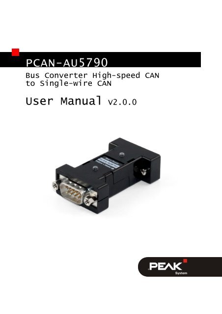
<strong>PCAN</strong>-<strong>AU5790</strong><br />
Bus Converter High-speed CAN<br />
to Single-wire CAN<br />
<strong>User</strong> <strong>Manual</strong> V2.0.0
<strong>PCAN</strong>-<strong>AU5790</strong> – <strong>User</strong> <strong>Manual</strong><br />
Products taken into account<br />
Product Name Model Part number<br />
<strong>PCAN</strong>-<strong>AU5790</strong> IPEH-002040<br />
CANopen® and CiA® are registered community trade marks of CAN in Automation<br />
e.V.<br />
All other product names mentioned in this document may be the trademarks or<br />
registered trademarks of their respective companies. They are not explicitly marked<br />
by “” and “®”.<br />
© 2012 <strong>PEAK</strong>-<strong>System</strong> Technik GmbH<br />
<strong>PEAK</strong>-<strong>System</strong> Technik GmbH<br />
Otto-Roehm-Strasse 69<br />
64293 Darmstadt<br />
Germany<br />
Phone: +49 (0)6151 8173-20<br />
Fax: +49 (0)6151 8173-29<br />
www.peak-system.com<br />
info@peak-system.com<br />
Document version 2.0.0 (2012-06-27)<br />
2
<strong>PCAN</strong>-<strong>AU5790</strong> – <strong>User</strong> <strong>Manual</strong><br />
Contents<br />
1 Introduction 4<br />
1.1 Properties at a Glance 4<br />
1.2 Scope of Supply 5<br />
2 Connectors 6<br />
2.1 D-Sub Socket: High-speed CAN, Primary Voltage<br />
Supply 6<br />
2.1.1<br />
2.1.2<br />
Supply Voltage Vmain<br />
Voltage Supply Alternatively Via Pin 9<br />
6<br />
7<br />
2.1.3 Termination High-Speed-CAN 8<br />
2.2 D-Sub Plug: Single-wire CAN, Secondary<br />
Voltage Supply 9<br />
2.2.1 Ground Connection (GND) 9<br />
2.2.2<br />
2.2.3<br />
Additional Supply Voltage Vaux<br />
Termination Single-wire CAN<br />
9<br />
9<br />
3 Operation 10<br />
3.1 Status LEDs 10<br />
3.2 Single-wire CAN Operation Modes 10<br />
3.2.1 Normal Mode 11<br />
3.2.2 High-speed Mode 11<br />
3.2.3 Wake-up Mode 11<br />
3.3 CAN Bit Rate 12<br />
4 Technical Specifications <strong>PCAN</strong>-<strong>AU5790</strong> 13<br />
Appendix A CE Certificate 15<br />
Appendix B Dimension Drawing 16<br />
Appendix C Quick Reference 17<br />
3
<strong>PCAN</strong>-<strong>AU5790</strong> – <strong>User</strong> <strong>Manual</strong><br />
1 Introduction<br />
Tip: At the end of this manual (Appendix C) you can find a<br />
Quick Reference with brief information about the installation<br />
and operation of the <strong>PCAN</strong>-<strong>AU5790</strong>.<br />
The bus converter <strong>PCAN</strong>-<strong>AU5790</strong> establishes a connection between<br />
a High-speed CAN bus (ISO 11898-2) and a Single-wire CAN bus<br />
(SAE J2411). It is designed for direct connection of a CAN interface<br />
of the <strong>PCAN</strong> series (e.g. <strong>PCAN</strong>-USB) to a Single-wire CAN bus. The<br />
term <strong>AU5790</strong> refers to the transceiver of the same name. This (or a<br />
compatible transceiver) is used in the bus converter for the<br />
connection to the Single-wire CAN bus.<br />
Single-wire CAN<br />
Single-wire CAN only uses one signal line in contrast to High-speed<br />
CAN. Single-wire CAN is used in motor vehicles. The bodywork<br />
functions as ground of the bus. Therefore the Single-wire CAN bus<br />
actually consists of an unipolar line and thus reduces the overhead<br />
of the wiring through the motor vehicle. On the other hand the<br />
highest possible transmission rate is considerably lower than for<br />
High-speed CAN.<br />
1.1 Properties at a Glance<br />
Three operation modes for Single-wire CAN (Normal/Highspeed/Wake-up),<br />
configurable by slide switch<br />
Status LEDs for power supply and wake-up signals<br />
Voltage supply (5 V, 150 mA) via High-speed CAN connection<br />
On voltage supply with lower current delivery than 150 mA additional<br />
voltage supply (12 V) via Single-wire CAN connection<br />
necessary<br />
4
<strong>PCAN</strong>-<strong>AU5790</strong> – <strong>User</strong> <strong>Manual</strong><br />
Operating temperature range from 0 to 70 °C (32 to 185 °F)<br />
Note: You can find additional information about the properties<br />
and the behavior of the Single-wire CAN transceiver <strong>AU5790</strong> in<br />
the corresponding data sheet which you can download, for<br />
example, from the NXP website: www.nxp.com<br />
1.2 Scope of Supply<br />
Bus converter <strong>PCAN</strong>-<strong>AU5790</strong> (plastic casing with two ports and<br />
slide switch)<br />
<strong>Manual</strong> in PDF format<br />
5
<strong>PCAN</strong>-<strong>AU5790</strong> – <strong>User</strong> <strong>Manual</strong><br />
2 Connectors<br />
2.1 D-Sub Socket: High-speed CAN, Primary<br />
Voltage Supply<br />
The bus converter <strong>PCAN</strong>-<strong>AU5790</strong> is designed for the use as add-on<br />
module for a CAN interface of the <strong>PCAN</strong> series (e.g. <strong>PCAN</strong>-USB). As<br />
an extension it is directly connected to the CAN interface with the<br />
High-speed CAN side (D-Sub socket).<br />
Attention! Risk of short circuit! When you connect the <strong>PCAN</strong>-<br />
<strong>AU5790</strong> to or remove it from the CAN interface, latter must be<br />
turned off (without supply voltage). The <strong>PCAN</strong>-<strong>AU5790</strong> or other<br />
electronic components may be damaged.<br />
Figure 1: Pin assignment High-speed CAN side (D-Sub socket)<br />
2.1.1 Supply Voltage Vmain<br />
For the bus converter operation a direct voltage of 5 V (V main) is<br />
needed. The voltage source must be able to supply a current of up<br />
to 150 mA.<br />
6
<strong>PCAN</strong>-<strong>AU5790</strong> – <strong>User</strong> <strong>Manual</strong><br />
Note: If the voltage source cannot supply a current up to<br />
150 mA, an additional voltage supply must be used on V aux at<br />
the Single-wire CAN connection. This applies, for example, to<br />
all CAN interfaces of the <strong>PCAN</strong> series with galvanic isolation<br />
(“opto-decoupled”).<br />
For the voltage supply of the bus converter a CAN interface of the<br />
<strong>PCAN</strong> series must be configured so that the 5-Volts supply of the<br />
computer is routed to either pin 1 or pin 9 of the High-speed CAN<br />
connector. Please take detailed notes from the documentation of the<br />
respective CAN interface.<br />
When the 5-Volt supply is active, the red LED on the <strong>PCAN</strong>-<strong>AU5790</strong><br />
is on.<br />
2.1.2 Voltage Supply Alternatively Via Pin 9<br />
The bus converter is pre-configured to be supplied via pin 1 of the<br />
connector. Alternatively the voltage supply V main can be done via<br />
pin 9. For that a modification must be done on the PCB of the <strong>PCAN</strong>-<br />
<strong>AU5790</strong>.<br />
Important note: Perform the following procedure with special<br />
care, because soldering can incur unintentional short circuits<br />
on the PCB. This can lead to damage of the bus converter or the<br />
connected hardware.<br />
Do the following to route the voltage supply via pin 9:<br />
1. Open the plastic casing of the <strong>PCAN</strong>-<strong>AU5790</strong> by cautiously<br />
levering the latches on both sides, e.g. with a flat tip<br />
screwdriver.<br />
2. On the bottom side of the PCB in the soldering field JP1, a 0-<br />
Ohm resistor connects the lower two pads (see Figure 2).<br />
Unsolder the resistor and replace it so that it connects the<br />
7
<strong>PCAN</strong>-<strong>AU5790</strong> – <strong>User</strong> <strong>Manual</strong><br />
upper two pads. Alternatively, you can remove the resistor<br />
and connect the pads with a solder bridge.<br />
Figure 2: Position of soldering field JP1<br />
on the bottom side of the opened <strong>PCAN</strong>-<strong>AU5790</strong><br />
Voltage supply via… Pin 1 Pin 9<br />
Connected pads on JP1<br />
3. Put together the two parts of the casing on the bus<br />
converter. Pay attention to the correct position because of<br />
the LEDs and the switch.<br />
2.1.3 Termination High-Speed-CAN<br />
The High-speed CAN lines CAN_L and CAN_H are terminated in the<br />
bus converter with an 120-Ohm resistor. This termination is<br />
unalterable.<br />
8
<strong>PCAN</strong>-<strong>AU5790</strong> – <strong>User</strong> <strong>Manual</strong><br />
2.2 D-Sub Plug: Single-wire CAN, Secondary<br />
Voltage Supply<br />
Figure 3: Pin assignment Single-wire CAN side (D-Sub plug)<br />
2.2.1 Ground Connection (GND)<br />
For pin allocation it has to be taken into account that a ground<br />
connection (via GND) to all other CAN nodes is needed on the<br />
Single-wire CAN bus. In motor vehicles this is usually done via<br />
bodywork.<br />
2.2.2 Additional Supply Voltage Vaux<br />
The additional supply voltage V aux with 12 V DC (e.g. car battery, 6 -<br />
16 V possible, at wake-up mode 12 V min.) is needed if the 5-Volt<br />
supply V main at the High-speed CAN connector cannot provide up to<br />
150 mA current. This applies, for example, to all CAN interfaces of<br />
the <strong>PCAN</strong> series with galvanic isolation (“opto-decoupled”).<br />
Note: The 5-Volt supply V main at the High-speed CAN connector<br />
must remain when using V aux.<br />
2.2.3 Termination Single-wire CAN<br />
On the Single-wire CAN side the <strong>PCAN</strong>-<strong>AU5790</strong> is terminated internally<br />
with 5.1 kΩ. The Single-wire CAN specification does not<br />
include an external termination of the bus converter with a<br />
terminating resistor.<br />
9
<strong>PCAN</strong>-<strong>AU5790</strong> – <strong>User</strong> <strong>Manual</strong><br />
3 Operation<br />
3.1 Status LEDs<br />
LED Meaning<br />
Red Power supply 5 V<br />
Yellow Reception/transmission of wake-up signals on the Single-wire CAN<br />
bus (see also section 3.2.3 Wake-up Mode on page 11)<br />
3.2 Single-wire CAN Operation Modes<br />
The <strong>PCAN</strong>-<strong>AU5790</strong> can be operated in three different Single-wire<br />
CAN modes. They are determined by the slide switch at the side of<br />
the casing.<br />
Switch position Mode Description<br />
Middle Normal Up to 33.3 kbit/s, with waveshaping<br />
Right High-speed Up to 83.3 kbit/s, without waveshaping<br />
Left Wake-up<br />
Like normal mode, but with increased<br />
signal levels<br />
The Sleep mode, defined in addition for Single-wire CAN, is not<br />
supported.<br />
Note: To prevent mistakes: The term “high-speed mode” in this<br />
manual refers to Single-wire CAN and does not have a direct<br />
relation to High-speed CAN.<br />
10
<strong>PCAN</strong>-<strong>AU5790</strong> – <strong>User</strong> <strong>Manual</strong><br />
3.2.1 Normal Mode<br />
This mode is used for normal operation. Bit rates up to 33.3 kbit/s<br />
are supported. The output of signals on the Single-wire CAN bus is<br />
done with waveshaping. The voltage slew rate and the shape of the<br />
rising edge as well as the beginning of the falling edge are controlled.<br />
This behavior contributes to the minimization of EM<br />
emissions.<br />
3.2.2 High-speed Mode<br />
The <strong>PCAN</strong>-<strong>AU5790</strong> provides a high-speed mode for the transfer of<br />
software or diagnostic data, for example. Bit rates up to 83.3 kbit/s<br />
can be used. In contrast to the normal mode, the waveshaping<br />
function is deactivated, i.e. the bus driver is switched on and off as<br />
fast as possible to be able to reach higher bit rates. However, the<br />
electromagnetic compatibility (EMC) consequently is reduced in<br />
comparison to the normal mode.<br />
The high-speed mode is only used in special cases and shouldn’t be<br />
used for regular operation of a Single-wire CAN bus.<br />
3.2.3 Wake-up Mode<br />
In this mode transmission is done with an increased level in comparison<br />
to the normal mode. An activation of all “sleeping” bus<br />
nodes in the network results from it. Sleeping bus nodes ignore<br />
normal 4-Volt levels and only react to levels with higher voltage<br />
(12 V). Because the <strong>PCAN</strong>-<strong>AU5790</strong> itself does not have a sleep<br />
mode, incoming signals are all interpreted in the same manner<br />
independently of their level (normal or wake-up).<br />
The yellow LED indicates a received or transmitted signal with<br />
wake-up level. After detection the LED switches off again with delay.<br />
Thus signals of short duration are also recognized.<br />
11
<strong>PCAN</strong>-<strong>AU5790</strong> – <strong>User</strong> <strong>Manual</strong><br />
3.3 CAN Bit Rate<br />
When operating the <strong>PCAN</strong>-<strong>AU5790</strong> it must be ensured that the bit<br />
rate on the High-speed CAN bus matches the one on the Single-wire<br />
CAN bus. No conversion or automatic adaptation of the bit rate is<br />
done in the bus converter.<br />
Usual bit rate for Single-wire CAN:<br />
33.3 kbit/s (normal mode, wake-up mode)<br />
83.3 kbit/s (high-speed mode)<br />
12
<strong>PCAN</strong>-<strong>AU5790</strong> – <strong>User</strong> <strong>Manual</strong><br />
4 Technical Specifications<br />
<strong>PCAN</strong>-<strong>AU5790</strong><br />
Power supply<br />
Supply voltage 5 V DC, at least 150 mA (via High-speed CAN<br />
connection)<br />
12 V DC additionally, if the available amperage of<br />
the 5-Volt supply < 150 mA (via Single-wire CAN<br />
connection; 6 - 16 V possible, at least 12 V for<br />
wake-up mode)<br />
Current consumption 20 mA average, 120 mA maximum<br />
High-speed CAN<br />
Specification ISO 11898-2<br />
CAN specifications 2.0A and 2.0B<br />
Transceiver PCA82C251<br />
Connector D-Sub socket, 9-pin, pin assignment according to<br />
specification CiA® 102<br />
Termination 120 Ω (unalterable)<br />
Single-wire CAN<br />
Specification SAE J2411<br />
Transceiver <strong>AU5790</strong> or compatible<br />
Connector D-Sub plug, 9-pin<br />
Termination 5.1 kΩ<br />
Operating modes (bit rates) normal (33.3 kbit/s), high-speed (83.3 kbit/s),<br />
wake-up (33.3 kbit/s)<br />
Wake-up LED (yellow)<br />
Pulse width > 0.5 s<br />
Delay time signal > 5 μs (at 11-Volt pulse)<br />
Threshold signal 8.2 V<br />
13
<strong>PCAN</strong>-<strong>AU5790</strong> – <strong>User</strong> <strong>Manual</strong><br />
Measures<br />
Size 63 x 34 x 19 mm (L x W x H)<br />
See also dimension drawing in Appendix B on<br />
page 16<br />
Weight 26 g<br />
Environment<br />
Operating temperature 0 - 70 °C (32 - 158 °F)<br />
Temperature for storage and -40 - +100 °C (-40 - +212 °F)<br />
transport<br />
Relative humidity 15% - 90%, not condensing<br />
EMC EN 55024:2003-10<br />
EN 55022:2008-05<br />
EC directive 2004/108/EG<br />
Ingress protection (IEC 60529) IP20<br />
14
<strong>PCAN</strong>-<strong>AU5790</strong> – <strong>User</strong> <strong>Manual</strong><br />
Appendix A CE Certificate<br />
15
<strong>PCAN</strong>-<strong>AU5790</strong> – <strong>User</strong> <strong>Manual</strong><br />
Appendix B Dimension Drawing<br />
Figure 4: Top view and side view <strong>PCAN</strong>-<strong>AU5790</strong>.<br />
The figure does not show the original size.<br />
16
<strong>PCAN</strong>-<strong>AU5790</strong> – <strong>User</strong> <strong>Manual</strong><br />
Appendix C Quick Reference<br />
Procedure for connecting to CAN interface of the <strong>PCAN</strong> series:<br />
1. On the CAN interface, enable the routing of the 5-Volt<br />
supply to pin 1 of the D-Sub connector (see documentation<br />
of the CAN interface).<br />
2. Plug the <strong>PCAN</strong>-<strong>AU5790</strong> with its D-Sub socket (High-speed<br />
CAN) onto the D-Sub plug of the CAN interface.<br />
3. Only CAN interfaces with galvanic isolation (“optodecoupled”):<br />
On the Single-wire CAN side of the <strong>PCAN</strong>-<br />
<strong>AU5790</strong>, connect an additional voltage supply V aux.<br />
Single-wire CAN Connector<br />
Switch for Single-wire CAN Modes<br />
V aux = 12 V DC, e.g. car battery<br />
(6 - 16 V possible, at least 12 V for wake-up<br />
mode)<br />
Switch position Mode Description<br />
Middle Normal Up to 33.3 kbit/s, with waveshaping<br />
Right High-speed Up to 83.3 kbit/s, without wave shaping<br />
Left Wake-up<br />
Like normal mode, but with increased<br />
signal levels<br />
Status LEDs<br />
LED Meaning<br />
Red Power supply 5 V<br />
Yellow Reception/transmission of wake-up signals on the Single-wire CAN<br />
bus<br />
17


![English - Low Quality [7.2 MB] - PEAK-System](https://img.yumpu.com/5931738/1/184x260/english-low-quality-72-mb-peak-system.jpg?quality=85)


