Measurement Method for Acoustic Emission Signals in Concrete - IfB
Measurement Method for Acoustic Emission Signals in Concrete - IfB
Measurement Method for Acoustic Emission Signals in Concrete - IfB

You also want an ePaper? Increase the reach of your titles
YUMPU automatically turns print PDFs into web optimized ePapers that Google loves.
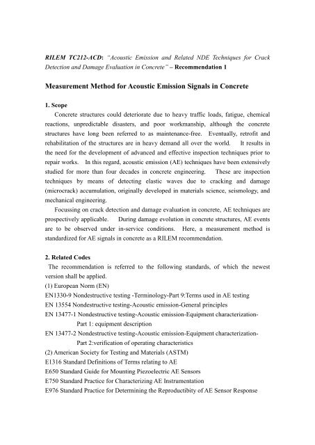
RILEM TC212-ACD: “<strong>Acoustic</strong> <strong>Emission</strong> and Related NDE Techniques <strong>for</strong> Crack<br />
Detection and Damage Evaluation <strong>in</strong> <strong>Concrete</strong>” – Recommendation 1<br />
<strong>Measurement</strong> <strong>Method</strong> <strong>for</strong> <strong>Acoustic</strong> <strong>Emission</strong> <strong>Signals</strong> <strong>in</strong> <strong>Concrete</strong><br />
1. Scope<br />
<strong>Concrete</strong> structures could deteriorate due to heavy traffic loads, fatigue, chemical<br />
reactions, unpredictable disasters, and poor workmanship, although the concrete<br />
structures have long been referred to as ma<strong>in</strong>tenance-free. Eventually, retrofit and<br />
rehabilitation of the structures are <strong>in</strong> heavy demand all over the world. It results <strong>in</strong><br />
the need <strong>for</strong> the development of advanced and effective <strong>in</strong>spection techniques prior to<br />
repair works. In this regard, acoustic emission (AE) techniques have been extensively<br />
studied <strong>for</strong> more than four decades <strong>in</strong> concrete eng<strong>in</strong>eer<strong>in</strong>g. These are <strong>in</strong>spection<br />
techniques by means of detect<strong>in</strong>g elastic waves due to crack<strong>in</strong>g and damage<br />
(microcrack) accumulation, orig<strong>in</strong>ally developed <strong>in</strong> materials science, seismology, and<br />
mechanical eng<strong>in</strong>eer<strong>in</strong>g.<br />
Focuss<strong>in</strong>g on crack detection and damage evaluation <strong>in</strong> concrete, AE techniques are<br />
prospectively applicable. Dur<strong>in</strong>g damage evolution <strong>in</strong> concrete structures, AE events<br />
are to be observed under <strong>in</strong>-service conditions. Here, a measurement method is<br />
standardized <strong>for</strong> AE signals <strong>in</strong> concrete as a RILEM recommendation.<br />
2. Related Codes<br />
The recommendation is referred to the follow<strong>in</strong>g standards, of which the newest<br />
version shall be applied.<br />
(1) European Norm (EN)<br />
EN1330-9 Nondestructive test<strong>in</strong>g -Term<strong>in</strong>ology-Part 9:Terms used <strong>in</strong> AE test<strong>in</strong>g<br />
EN 13554 Nondestructive test<strong>in</strong>g-<strong>Acoustic</strong> emission-General pr<strong>in</strong>ciples<br />
EN 13477-1 Nondestructive test<strong>in</strong>g-<strong>Acoustic</strong> emission-Equipment characterization-<br />
Part 1: equipment description<br />
EN 13477-2 Nondestructive test<strong>in</strong>g-<strong>Acoustic</strong> emission-Equipment characterization-<br />
Part 2:verification of operat<strong>in</strong>g characteristics<br />
(2) American Society <strong>for</strong> Test<strong>in</strong>g and Materials (ASTM)<br />
E1316 Standard Def<strong>in</strong>itions of Terms relat<strong>in</strong>g to AE<br />
E650 Standard Guide <strong>for</strong> Mount<strong>in</strong>g Piezoelectric AE Sensors<br />
E750 Standard Practice <strong>for</strong> Characteriz<strong>in</strong>g AE Instrumentation<br />
E976 Standard Practice <strong>for</strong> Determ<strong>in</strong><strong>in</strong>g the Reproductibity of AE Sensor Response
E1106 Standard <strong>Method</strong> <strong>for</strong> Primary Calibration of AE Sensors<br />
(3) American Society <strong>for</strong> Nondestructive Test<strong>in</strong>g (ASNT)<br />
DGZfP-SE1 Nondestructive Test<strong>in</strong>g: <strong>Acoustic</strong> <strong>Emission</strong> Terms<br />
DGZfP-SE2 Guide l<strong>in</strong>e <strong>for</strong> AE Sensor Calibration<br />
DGZfP-SE3 Guide l<strong>in</strong>e <strong>for</strong> AE Characterization dur<strong>in</strong>g AE Test<br />
(4) French Association <strong>for</strong> Standards (AFNOR)<br />
NF A09-350 Nondestructive Test<strong>in</strong>g-Vocabulary used <strong>in</strong> <strong>Acoustic</strong> <strong>Emission</strong><br />
(5) European Work<strong>in</strong>g Group on <strong>Acoustic</strong> <strong>Emission</strong> (EWGAE)<br />
EWGAE Codes <strong>for</strong> AE Exam<strong>in</strong>ation: Code I-Location of Discrete <strong>Acoustic</strong> Events<br />
EWGAE Codes <strong>for</strong> AE Exam<strong>in</strong>ation: Code IV-Def<strong>in</strong>ition of Terms <strong>in</strong> AE<br />
(6) Japanese Society <strong>for</strong> Nondestructive Inspection (JSNDI)<br />
NDIS 2110 Calibration of AE Sensors<br />
NDIS 2421 Recommendation Practice <strong>for</strong> In Situ Monitor<strong>in</strong>g AE of <strong>Concrete</strong> Structures<br />
by AE<br />
3. Def<strong>in</strong>itions of technical terms<br />
a) <strong>Acoustic</strong> emission (AE): transient elastic waves generated by the release of energy<br />
with<strong>in</strong> a material. Microscopic fracture <strong>in</strong> concrete takes place with the release of<br />
stored stra<strong>in</strong> energy as nucleat<strong>in</strong>g micro-cracks and generat<strong>in</strong>g elastic waves. These<br />
waves due to crack nucleation are referred to as AE waves, which propagate <strong>in</strong>side a<br />
material and are detected by an AE sensor as shown <strong>in</strong> Fig. 1.<br />
Fig. 1 Detection of AE wave.
) AE signal: The electrical signal detected at a sensor, which is converted through the<br />
detection of AE wave (elastic wave).<br />
c) Burst emission: A description of the signal that has a rapid rise to peak and slower<br />
decay to the noise level. Burst-type AE signals are typically detected <strong>in</strong> concrete. In<br />
contrast, under plastic de<strong>for</strong>mation <strong>in</strong> metal, emissions are observed cont<strong>in</strong>uously<br />
without the decay. This is normally named “cont<strong>in</strong>uous emission”.<br />
d) Channel: One l<strong>in</strong>e of AE signal detected by AE sensor and processed by the other<br />
devises.<br />
e) Hit: A hit is the term to <strong>in</strong>dicate that a given AE channel has detected and processed<br />
one AE transient. Count<strong>in</strong>g methods of AE signals are later described <strong>in</strong> the section<br />
of “5. signal analysis and AE parameters” .<br />
f) Event: AE wave can be detected <strong>in</strong> the <strong>for</strong>m of hits on one or more channels. One<br />
event is a group of AE hits received from a s<strong>in</strong>gle source by two or more channels<br />
which is located.<br />
g) Array: Spatial arrangement of AE sensors <strong>for</strong> locat<strong>in</strong>g AE sources<br />
h) Attenuation: The observed loss of a signal as it travels through a medium.<br />
i) Noises: <strong>Signals</strong> produced by causes other than AE phenomena. Elim<strong>in</strong>ation of<br />
noises is essential <strong>for</strong> effective detection of AE signals.<br />
4. Measur<strong>in</strong>g system<br />
AE measur<strong>in</strong>g system shall consist of the follow<strong>in</strong>g devices with prescribed<br />
functions. A basic system is illustrated <strong>in</strong> Fig. 2, where only analog devices are shown.<br />
Follow<strong>in</strong>g this system, a digital signal-processor is presently equipped.<br />
Fig. 2 AE measurement system.
4.1 Sensor<br />
AE sensors shall be sensitive enough to detect AE signals generated <strong>in</strong> the target<br />
structure, tak<strong>in</strong>g acoustic coupl<strong>in</strong>g <strong>in</strong>to consideration. They convert elastic waves<br />
(motions) on the surface of a material <strong>in</strong>to electric signals, preferably, without any<br />
distortions. Usually, a resonance-type sensor is most sensitive around the resonant<br />
frequency, while a broad-band sensor has approximately flat response <strong>in</strong> the range but is<br />
less sensitive than the resonance-type. AE sensor shall be robust enough aga<strong>in</strong>st<br />
temperature change, moisture condition and mechanical vibrations <strong>in</strong> the environments.<br />
Sensitivity calibration of AE sensors shall be per<strong>for</strong>med by employ<strong>in</strong>g the standard<br />
source. A simulated AE source due to pencil-lead break is def<strong>in</strong>ed <strong>in</strong> NDIS 2110 and<br />
others. Along with a guide-r<strong>in</strong>g, a standard source is illustrated <strong>in</strong> Fig. 3.<br />
4.2 Amplifier<br />
Fig. 3 Standard AE source.<br />
Amplifiers normally consist of the pre-amplifier and the ma<strong>in</strong> amplifier as shown <strong>in</strong><br />
Fig. 2. The pre-amplifier shall be located as close as possible to AE sensor. The<br />
<strong>in</strong>ternal noise of the amplifier shall be <strong>in</strong>herently low and less than 20 �V as the peak<br />
voltage converted by <strong>in</strong>put voltage. The amplifier shall be robust enough aga<strong>in</strong>st the<br />
environmental conditions and be protected properly.<br />
4.3 Filter<br />
The frequency range shall be determ<strong>in</strong>ed prior to the measurement, tak<strong>in</strong>g <strong>in</strong>to<br />
account the per<strong>for</strong>mance of AE sensors and the amplifiers. Selection of the frequency<br />
rage is closely related to elim<strong>in</strong>ation of noises. In concrete, the use of a band-pass<br />
filter between several kHz and several 100 kHz is recommended.
5. Signal analysis and AE parameters<br />
One wave<strong>for</strong>m is to be counted as one AE event, while the cycles over the threshold<br />
level are named as AE r<strong>in</strong>g-down counts (or simply “counts”). Here, the threshold is<br />
a preset voltage level, which has to be exceeded be<strong>for</strong>e one AE signal is detected and<br />
processed. <strong>Method</strong>s <strong>for</strong> AE count<strong>in</strong>g are illustrated <strong>in</strong> Fig. 4. In the case of<br />
multi-channel observation, AE occurrence is monitored at each sensor location. At<br />
some sensors, AE signals may not be observed due to attenuation or undetectable<br />
propagation path. The number of the events which are counted at one of the channels<br />
corresponds to the number of AE hits def<strong>in</strong>ed above.<br />
Fig. 4 AE count<strong>in</strong>g methods.<br />
In addition to AE count, AE hit and AE event, the follow<strong>in</strong>g AE parameters shall be<br />
obta<strong>in</strong>ed by the measurement system.
1) Peak amplitude<br />
2) AE energy<br />
3) Rise time<br />
4) Duration time<br />
5) Arrival time differences <strong>in</strong> AE sensor array<br />
6) External parameters : The measurement system shall be able to obta<strong>in</strong> time<br />
<strong>in</strong><strong>for</strong>mation along with AE parameters. In addition, such external parameters<br />
as load, stra<strong>in</strong> and so <strong>for</strong>th are preferably recorded <strong>in</strong> the system.<br />
The wave<strong>for</strong>m parameters of arrival time, duration and peak amplitude are displayed<br />
<strong>in</strong> Fig. 5. show<strong>in</strong>g the threshold level. The rise time means a duration from the<br />
arrival to the peak. There exist a variety of def<strong>in</strong>itions on AE energy. In pr<strong>in</strong>ciple,<br />
AE energy corresponds to an area of the envelope of the wave<strong>for</strong>m.<br />
6. Setup and <strong>Measurement</strong><br />
6.1 Sensor setup<br />
Fig. 5 AE wave<strong>for</strong>m parameters.<br />
AE sensors shall be calibrated properly <strong>in</strong> advance of the measurement. They are<br />
attached at proper locations to cover the target area. The period of the measurement<br />
shall be prescribed, depend<strong>in</strong>g on the follow<strong>in</strong>g conditions:<br />
a) Propagation property of AE signals <strong>in</strong> the target structure<br />
b) Stress distribution <strong>in</strong> the structure under <strong>in</strong>spection<br />
6.2 Environmental noises<br />
In advance to AE measurement, the noise level shall be estimated. Then,<br />
counteract aga<strong>in</strong>st external noises, w<strong>in</strong>d, ra<strong>in</strong>, sunsh<strong>in</strong>e and so <strong>for</strong>th shall be conducted
to decrease the noise level as low as possible. In the case that the noises have similar<br />
frequency contents, amplitudes to AE signals or sources of the noises are unknown,<br />
characteristics of the noises shall be estimated prior to the measurement. Based on<br />
this result, separation of AE signals from the noises shall be achieved. In this respect,<br />
the use of filters is applicable after determ<strong>in</strong><strong>in</strong>g the proper frequency range.<br />
6.3 <strong>Measurement</strong><br />
In an exist<strong>in</strong>g structure, a measurement is normally conducted under loads which<br />
must not make a critical damage on functions of the structure to detect and locate active<br />
cracks. Based on the spatial area to be covered by AE sensors, those of proper<br />
frequency characteristics shall be selected. In advance to the test, attenuation<br />
properties of the target structure shall be estimated, by employ<strong>in</strong>g the standard source or<br />
the equivalent. Based on this <strong>in</strong><strong>for</strong>mation, sensor array shall be determ<strong>in</strong>ed so as to<br />
keep the equivalent sensitivities <strong>in</strong> all the sensors. AE signals due to crack<strong>in</strong>g shall be<br />
detected properly <strong>for</strong> the duration of the measurement. Concern<strong>in</strong>g AE parameters<br />
detected, their trend, distribution, correlation, and locations are monitored. In<br />
addition, multi-channel observation provides to locate AE sources, by apply<strong>in</strong>g the<br />
location rout<strong>in</strong>e available.<br />
6.4 System <strong>in</strong>spection<br />
Sensitivity of AE channels shall be conducted rout<strong>in</strong>ely by employ<strong>in</strong>g the standard<br />
source. Variation with<strong>in</strong> the channels shall be less than 3%.<br />
6.5 Storage of data<br />
The system shall be equipped with an enough memory to record the data measured.<br />
It is preferable that all the data recorded are analyzed digitally by computer.<br />
7. Documents<br />
Documents to report the results shall conta<strong>in</strong> the follow<strong>in</strong>g articles:<br />
a) Date<br />
b) Test person<br />
c) Devices<br />
d) <strong>Measurement</strong> locations<br />
e) Results of system <strong>in</strong>spection be<strong>for</strong>e and after the setup<br />
f) Results of analytical data be<strong>for</strong>e and after the setup