
You also want an ePaper? Increase the reach of your titles
YUMPU automatically turns print PDFs into web optimized ePapers that Google loves.
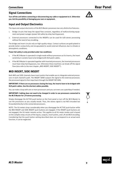
Connections<br />
Signal Connections<br />
Turn off the unit before connecting or disconnecting any cable or equipment to it. Otherwise<br />
you risk the possibility of damaging your ears or equipment.<br />
Input and Output Electronics<br />
The input and output electronics of the M/S <strong>Master</strong> possesses two very distinctive features:<br />
1. Bridge circuits that keep the signal flow constant, regardless of malfunctioning equipment<br />
and power outages (power fail safety by relay hard bypasses).<br />
2. External processors connected to the INSERTs can be used for A/B stereo processing<br />
without the need of any recabling.<br />
The bridge and insert circuits rely on high-quality relays. Contact surfaces are gold-plated to<br />
provide better conductivity and encapsulated to avoid external influences due to climate or<br />
atmospheric conditions.<br />
Power fail safety is only provided under two conditions:<br />
1. If the M/S <strong>Master</strong> is operated in single mode without processors at its inserts, the insert<br />
send/return sockets have to be bridged with XLR patch cables.<br />
2. If the M/S <strong>Master</strong> is operated together with inserted processors, the inserted processors<br />
must have relay hard bypasses, too. Otherwise these machines can break off the signal<br />
flow (also refer to the next chapter „MID INSERT, SIDE INSERT“).<br />
MID INSERT, SIDE INSERT<br />
Both MID and SIDE channels have insert points that enable you to integrate external processors<br />
in each channel‘s path. The INSERT SEND outputs the signal to the external processor;<br />
the processed signal is then input back through the INSERT RETURN.<br />
IMPORTANT: If there are no processors closing the loop, the inserts have to be bridged with<br />
XLR patch cables. Use the shortest cables possible.<br />
You can make a loop with one or more processors and you can even use a patchbay if needed.<br />
IMPORTANT: Cabling does not need to be changed in order to use processors connected to<br />
the M/S <strong>Master</strong> for L/R stereo processing.<br />
Simply disengage the ACTIVE push button on the front panel or turn off the M/S <strong>Master</strong> to<br />
use the processors as you usually would. Thus, the stereo signal is not M/S encoded but<br />
forwarded directly to the connected processors.<br />
NOTE: The VU-meters drop considerably when you disengage the ACTIVE push button while<br />
the MID INSERT and SIDE INSERT push buttons are engaged. If the INSERT push buttons are<br />
not engaged, the VU-meter remains active. This applies to all VU-meter modes and is based<br />
on the complex relay circuits of the inputs, outputs, insert points, and L/R and M/S encoding.<br />
Considering that the push button setting described does not correspond to an actual work<br />
function, it can be neglected.<br />
M/S <strong>Master</strong><br />
9<br />
Rear Panel