Commercial Self-Contained - Trane
Commercial Self-Contained - Trane
Commercial Self-Contained - Trane

Create successful ePaper yourself
Turn your PDF publications into a flip-book with our unique Google optimized e-Paper software.
<strong>Commercial</strong> <strong>Self</strong>-<strong>Contained</strong><br />
IntelliPak Signature Series<br />
20-110 Ton Water-Cooled Air Conditioners<br />
20-60 Ton Air-Cooled Air Conditioners<br />
Remote Air-Cooled Condensers<br />
June 2006 PKG-PRC002-EN
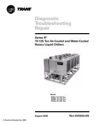
Affordable <strong>Self</strong>-<strong>Contained</strong> Value from <strong>Trane</strong>…<br />
<strong>Trane</strong>’s advanced technology brings unmatched reliability, high performance, and affordable cost!<br />
2-inch flat filter<br />
box inside unit<br />
casing<br />
Internally trapped<br />
drain for low cost<br />
installation<br />
Waterside economizer<br />
(cleanable option shown)<br />
Waterside valve<br />
package option to<br />
enhance system<br />
efficiency<br />
2<br />
© 2005 American Standard — All rights reserved<br />
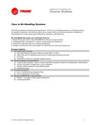
Introduction<br />
Inte liPak Signature Series <strong>Self</strong>-<strong>Contained</strong> Units<br />
Sight glasses with<br />
ports for viewing<br />
while unit is running<br />
Two-bolt connection on cleanable<br />
condenser for quick, easy<br />
maintenance<br />
Unit mounted microprocessor<br />
control with easy-to-read human<br />
interface panel<br />
Swing out VFO panel with<br />
Tri-VFO for efficient VAV<br />
operation<br />
<strong>Trane</strong> 3-D ® Scroll Compressor<br />
for reliability, efficiency and<br />
quiet operation<br />
PKG-PRC002-EN
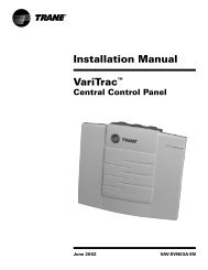
Contents<br />
Introduction 2<br />
Features and Benefits 4<br />
Application Considerations 8<br />
Selection Procedure 12<br />
Model Number Description 14<br />
General Data 17<br />
Performance Data 22<br />
Airside Pressure Drops 22<br />
Waterside Pressure Drops 30<br />
Waterflow 37<br />
Water-Cooled Units - R-22 Refrigerant 38<br />
Water-Cooled Units - 407c Refrigerant 70<br />
Air-Cooled Units 77<br />
Heating Coils 85<br />
Controls 86<br />
Electrical Data 97<br />
Dimensions and Weights 99<br />
Mechanical Specifications 114<br />
Options 115<br />
PKG-PRC002-EN 3
Why consider the<br />
Signature Series<br />
self-contained floor-by-floor<br />
systems?<br />
Improved Cash Management<br />
• Factory-installed and tested options<br />
reduce field labor and installation risk,<br />
while improving system reliability<br />
• Requires less sophisticated<br />
maintenance than built-up systems<br />
Tenant Satisfaction<br />
• Complete HVAC system on each floor<br />
minimizes tenant inconvenience during<br />
routine maintenance<br />
• Tenants can control system after hours<br />
to increase productivity and minimize<br />
expense<br />
Low First Cost<br />
• Reduce field labor, installation time, and<br />
cost with factory packaged controls and<br />
piping<br />
• Reduce installed tonnage up to 20<br />
percent by taking advantage of building<br />
diversity and VAV flexibility<br />
• Flexible air discharge arrangement<br />
matches most building configurations<br />
4<br />
Features and<br />
Benefits<br />
Lower Installed Cost<br />
• Single point power connection<br />
• Single point water connection<br />
• Factory commissioned and tested<br />
controls<br />
• Factory installed options<br />
• Internally trapped drain connection<br />
Economical Operation<br />
• Free cooling with waterside or airside<br />
economizer<br />
• Energy savings with floor-by-floor<br />
system since only units on floors<br />
requiring cooling need to operate<br />
• Significant annual energy consumption<br />
reduction due to partial occupancy<br />
after-hours, when compared to a<br />
central chilled water system<br />
• Simple heating alternatives include<br />
perimeter radiation and fan-powered<br />
VAV<br />
• Energy savings from the integrated<br />
water valve control using pump<br />
unloading<br />
Assured Acoustical Performance<br />
• Flexible, horizontal discharge plenum<br />
provides smooth airflow, reducing static<br />
pressure losses for optimum acoustical<br />
performance<br />
• Multiple compressor design reduces<br />
acoustical levels. Scroll compressor<br />
design smooths gas flow for quieter<br />
operation<br />
Indoor Air Quality (IAQ) Features<br />
• Sloped drain pan<br />
• Stainless steel sloped drain pan option<br />
• Internally trapped drain connection<br />
• Double wall construction option<br />
• Matt-faced fiberglass insulation<br />
• High efficiency throwaway filter option<br />
• Easily cleanable evaporator,<br />
condensers, and waterside<br />
economizers<br />
• Filter access door allows easy removal<br />
to encourage frequent filter changing<br />
• Airside economizer with Traq damper<br />
allows direct measurement and control<br />
of outdoor air<br />
Enhanced Serviceability<br />
• <strong>Self</strong>-supporting removable panels<br />
• Quick access service panel fasteners<br />
• Eye level control/service center<br />
• Refrigerant line sight glasses in view<br />
during operation<br />
Competitive Advantage<br />
• Increased capacity to meet today’s<br />
growing floor plates and building loads<br />
• Compact cabinet to minimize<br />
mechanical room requirements<br />
• Up to 17% more efficient than<br />
competitive units<br />
• Low leaving air temp capability to<br />
reduce fan motor energy, improve<br />
accoustical performance, and<br />
minimize duct sizes<br />
• Factory-installed and tested IntelliPak ®<br />
microprocessor controller<br />
PKG-PRC002-EN
Standard Features<br />
• 20 through 110 ton industrial/<br />
commercial water-cooled selfcontained<br />
units<br />
• 20 through 60 ton industrial/commercial<br />
remote air-cooled self-contained units<br />
• Fully integrated, factory-installed, and<br />
commissioned microelectronic controls<br />
• Unit mounted human interface panel<br />
with a two line x 40 character clear<br />
language (English, Spanish, or French)<br />
display and a 16-function keypad that<br />
includes custom, diagnostics, and<br />
service test mode menu keys<br />
• Improved <strong>Trane</strong> 3-D ® scroll compressor<br />
• Compressor lead/lag<br />
• CV or VAV system control<br />
• Low ambient compressor lockout<br />
adjustable control input<br />
• FROSTAT coil frost protection on all<br />
units<br />
• Daytime warmup (occupied mode) on<br />
units with heat and morning warmup<br />
operation on all units<br />
• Supply air static overpressurization<br />
protection on units with inlet guide<br />
vanes or variable frequency drives<br />
(VFDs)<br />
• Supply airflow proving<br />
• Supply air tempering control with<br />
heating option<br />
• Supply air heating control on VAV with<br />
hydronic heating option<br />
• Emergency stop input<br />
• Mappable sensors and setpoint sources<br />
• Occupied/unoccupied switching<br />
• Timed override activation<br />
• Refrigeration circuits are completely<br />
factory piped and tested on watercooled<br />
units<br />
• Factory piped and tested, mechanically<br />
cleanable water-cooled condensers<br />
• Two-bolt removable condenser<br />
waterboxes for quick and easy cleaning<br />
• Sloped drain pans to ensure complete<br />
condensate removal for IAQ<br />
• Internally trapped drain connection with<br />
cleanout<br />
• Internally isolated centrifugal supply fan<br />
• Sturdy-gauge galvanized steel<br />
framework with easily removable<br />
painted galvanized steel exterior panels<br />
• UL listing on standard options<br />
• Fan belts and grease lines are easily<br />
accessible<br />
• Access panels and clearance provided<br />
to clean both evaporator and waterside<br />
Features and<br />
Benefits<br />
economizer coil fins<br />
• Condensing pressure control on all<br />
variable water flow systems with valves<br />
• Programmable water purge during<br />
unoccupied mode<br />
• High entering air temperature limit<br />
• Low entering air temperature limit with<br />
waterside economizer or hydronic heat<br />
Optional Features<br />
• <strong>Trane</strong> communication interface module:<br />
ICS interface control module<br />
• Generic BAS interface<br />
• Comparative enthalpy control<br />
• Ventilation override from up to five<br />
external inputs<br />
• Remote human interface controls up to<br />
four units<br />
• Fully integrated, factory-installed/<br />
commissioned variable frequency drive<br />
control with or without optional<br />
integrated bypass<br />
• Fully integrated, factory-installed and<br />
commissioned inlet guide vanes on FC<br />
supply fan<br />
• Waterside economizer with factory<br />
installed piping and controls<br />
• Waterside modulating condensing<br />
temperature control valves include<br />
factory installed piping and control<br />
wiring<br />
• Removable cast iron headers on<br />
cleanable waterside economizer<br />
• Flexible horizontal discharge plenum<br />
with or without factory cut holes<br />
• Heating options include hot water,<br />
steam, and electric<br />
• Refrigerant suction discharge line<br />
service (shut-off) valves<br />
• Protective coatings for the unit and/or<br />
evaporator coils<br />
• Double wall construction<br />
• Stainless steel sloped drain pan<br />
• Medium efficiency throwaway filters<br />
• Through-the-door non-fused disconnect<br />
switch<br />
• <strong>Trane</strong>’s air quality Traq damper in<br />
airside economizer mixing box<br />
• High duct temperature thermostat<br />
• Dual electrical power connection<br />
•COreset input<br />
2<br />
• R407C refrigerant option available upon<br />
request<br />
• 2 - 4-inch filter racks for all sizes<br />
• Hi-capacity coils available for all sizes<br />
FC Fans With Inlet Guide Vanes<br />
<strong>Trane</strong>’s forward-curved fans with inlet<br />
guide vanes pre-rotate the air in the<br />
direction of the fan wheel. This decreases<br />
static pressure and horsepower. The<br />
unloading characteristics of a <strong>Trane</strong> FC<br />
fan with inlet guide vanes results in<br />
superior part load performance.<br />
Variable Frequency Drives (VFD)<br />
Variable frequency drives are factory<br />
installed, wired, and tested to provide<br />
supply fan motor speed modulation.<br />
VFD’s are quieter and more efficient than<br />
inlet quide vanes and may even be<br />
eligible for utility rebates. The VFD’s are<br />
available with and without a manual<br />
integrated bypass option, controlled<br />
through the human interface (HI) panel.<br />
Bypass control provides full nominal<br />
airflow control to CV zone setpoints in the<br />
unlikely event of a drive failure by<br />
manually placing the drive in the bypass<br />
mode.<br />
Field Installed Accessories<br />
• Airside economizer control with or<br />
without mixing box<br />
• Programmable sensors with or without<br />
night set back for CV and VAV systems<br />
• ICS zone sensors used with TracerTM system for zone control<br />
• Field installed module kits available for<br />
field upgrade of controls<br />
• Ultra low leak dampers for 0-100<br />
percent modulating fresh air<br />
economizer<br />
PKG-PRC002-EN 5
6<br />
Features and<br />
Benefits<br />
Integrated <strong>Self</strong>-<strong>Contained</strong><br />
Systems<br />
Integrated Comfort System (ICS)<br />
<strong>Trane</strong>’s Integrated Comfort system (ICS)<br />
increases job control by combining<br />
IntelliPak Signature Series selfcontained<br />
units and a Tracer building<br />
management system. This integrated<br />
system provides total building comfort<br />
and control. Building owners and<br />
managers not only save energy when<br />
using ICS—they have the ability to<br />
automate their facilities and the<br />
convenience of a control system<br />
interface.<br />
Simplifying The Comfort System<br />
<strong>Trane</strong>’s designers combined new<br />
technology and innovation to bring you<br />
more system capabilities and flexibility.<br />
Our Integrated Comfort System (ICS)<br />
with HVAC equipment is easy to use,<br />
install, commission, and service.<br />
Everything you need to know about your<br />
self-contained VAV system is available<br />
using Tracer, <strong>Trane</strong>’s family of building<br />
automation products. Tracer is a<br />
software package that minimizes custom<br />
programming requirements and allows<br />
easy system setup and control using<br />
your personal computer. By enabling all<br />
CSC units to communicate using the<br />
LonTalk interface, tranforming your<br />
heating and cooling units into a true<br />
system is made simple.<br />
Operating data from all system<br />
components is readily available for<br />
evaluation. You can control, monitor, and<br />
service your facility—all from your<br />
personal computer. That is why all Tracer<br />
controls have been designed to be<br />
LonTalk compatible.<br />
The IntelliPak self-contained unit, as part<br />
of <strong>Trane</strong> ICS, provides powerful<br />
maintenance monitoring, control, and<br />
reporting capabilities. Tracer places the<br />
self-contained unit in the appropriate<br />
operating mode for: system on/off, night<br />
setback, demand limiting, setpoint<br />
adjustment based on outside<br />
parameters and much more. You can<br />
monitor unit diagnostic conditions<br />
through Tracer such as: sensor failures,<br />
loss of supply airflow, and an inoperative<br />
refrigerant circuit.<br />
IntelliPak Signature Series self-contained<br />
monitoring points available using Tracer<br />
• Compressor on/off status<br />
• Ventilation status<br />
• Condenser water flow status<br />
• Heat status<br />
• Supply air pressure<br />
• Supply air temperature<br />
• Suction temperature of each circuit<br />
• Entering economizer water<br />
temperature<br />
• Zone temperature<br />
• Entering condenser water temperature<br />
• Supply air temperature reset signal<br />
• Morning warmup sensor temperature<br />
• Entering air temperature<br />
Tracer control points for IntelliPak<br />
Signature Series <strong>Self</strong>-<strong>Contained</strong> Units<br />
• Cooling and heating setpoints<br />
• VAV discharge air temperature<br />
setpoints<br />
• Supply air pressure setpoint<br />
• Cooling and heating enable/disable<br />
• Air economizer enable/disable<br />
• Airside economizer minimum position<br />
• Unit priority shutdown<br />
Commissioning, control, efficiency, and<br />
information…it simply all adds up to one<br />
reliable source…<strong>Trane</strong>.<br />
PKG-PRC002-EN
<strong>Trane</strong> 3-D Scroll Compressor<br />
Simple Design with 70% Fewer Parts<br />
Fewer parts than an equal capacity<br />
reciprocating compressor means<br />
significant reliability and efficiency<br />
benefits.The single orbiting scroll<br />
eliminates the need for pistons,<br />
connecting rods, wrist pins, and valves.<br />
Fewer parts lead to increased reliability.<br />
Fewer moving parts, less rotating mass,<br />
and less internal friction means greater<br />
efficiency than reciprocating compressors.<br />
Patented 3-D Scroll Compliance<br />
<strong>Trane</strong> 3-D scroll compliance provides<br />
important reliability and efficiency<br />
benefits. 3-D compliance allows the<br />
orbiting scrolls to touch in all three<br />
dimensions, forming a completely<br />
enclosed compression chamber that leads<br />
to increased efficiency. In addition, 3-D<br />
compliance means the orbiting scrolls only<br />
touch with enough force to create a seal—<br />
so there is no wear between the scroll<br />
plates.The fixed and orbiting scrolls are<br />
made of high strength cast iron—resulting<br />
in less thermal distortion, less leakage,<br />
and higher efficiencies. The most<br />
outstanding feature of the scroll<br />
compressor 3-D compliance is that<br />
slugging will not cause failure. In a<br />
reciprocating compressor, however, liquid<br />
or dirt can cause serious damage.<br />
Low Torque Variation<br />
The 3-D scroll compressor has a very<br />
smooth compression cycle with torque<br />
variations that are only 30 percent of that<br />
produced by a reciprocating compressor.<br />
This means the scroll compressor<br />
imposes very little stress on the motor for<br />
greater reliability. Low torque variation<br />
means reduced noise and vibration.<br />
Suction Gas Cooled Motor<br />
Compressor motor efficiency and<br />
reliability are further optimized with this<br />
design. Cool suction gas keeps the motor<br />
cooler for longer life and better efficiency.<br />
Proven Design Through Testing and<br />
Research<br />
With over twenty years of development<br />
and testing, <strong>Trane</strong> 3-D scroll compressors<br />
have undergone more than 400,000 hours<br />
of laboratory testing and field operation.<br />
This work combined with over 25 patents<br />
makes <strong>Trane</strong> the worldwide leader in air<br />
conditioning scroll compressor technology.<br />
Features and<br />
Benefits<br />
One of two matched scroll plates — the<br />
distinguishing feature of the scroll<br />
compressor.<br />
The Chart above illustrates low torque<br />
variation of 3-D Scroll compressors as<br />
compared to a reciprocating compressor.<br />
PKG-PRC002-EN 7
<strong>Self</strong>-<strong>Contained</strong> Acoustical<br />
Recommendations<br />
Successful acoustical results are<br />
dependent on many system design<br />
factors.<br />
Following are general acoustical<br />
recommendations. For more information,<br />
or if there is concern about a particular<br />
installation, contact a professional<br />
acoustical consultant.<br />
Location and Orientation of the<br />
Mechanical Equipment Room<br />
Locate the equipment room adjacent to<br />
stairwells, utility rooms, electrical closets,<br />
and rest rooms if possible (See figure<br />
below). This minimizes the acoustic<br />
effects and risk of workmanship or<br />
installation errors. Place the discharge<br />
and return air ductwork over these less<br />
acoustically sensitive areas, using vertical<br />
or horizontal fresh air shafts. Consult code<br />
requirements for fresh air and smoke<br />
purge constraints.<br />
8<br />
Application<br />
Considerations<br />
Return Air Ductwork<br />
Duct the return air into the mechanical<br />
equipment room. Connect ductwork to<br />
the unit if local code dictates. The return<br />
air ductwork must have an elbow inside<br />
the equipment room. This elbow will<br />
reduce sound transmissions through the<br />
return duct. Extend the ductwork from<br />
the elbow far enough to block the “line of<br />
sight” to the exterior of the equipment<br />
room. Use a minimum ductwork length<br />
of 15 feet to the equipment room<br />
exterior. Line the duct with two-inch,<br />
three-pound density insulation. Use<br />
multiple, small return ducts for better<br />
acoustical performance to the occupied<br />
space.<br />
Supply Air Ductwork<br />
Insulate the supply air duct with two-inch,<br />
three-pound density insulation. Extend<br />
this lining at least 15 feet out from the<br />
equipment room wall, keeping the duct<br />
aspect ratio as small as possible.<br />
Minimize large flat panels since they<br />
Equipment Room Location and Orientation<br />
<strong>Self</strong>-<strong>Contained</strong><br />
transmit sound. In addition, small aspect<br />
ratios will minimize potential “oil canning”<br />
of the duct due to flow turbulence.<br />
The flexible horizontal discharge plenum<br />
option helps avoid complicated ductwork<br />
transitions. Ductwork turning vanes<br />
typically improve pressure drop but<br />
degrade acoustical performance.<br />
Recommended Maximum Air Velocities<br />
The maximum recommended velocity<br />
for the discharge air duct is 2,000 fpm. The<br />
maximum recommended velocity for the<br />
return air duct is 1,000 fpm. Limit air<br />
velocities below these operating points to<br />
minimize the risk of flow turbulence that<br />
causes regenerated noise. Using round<br />
supply duct and static regain allows<br />
maximum discharge air velocities up to<br />
3,000 fpm. Lining round supply duct also<br />
substantially lowers frequency noise<br />
attenuation. However, flow regenerated<br />
noise potential increases dramatically at<br />
air velocities over 3000 fpm.<br />
PKG-PRC002-EN
Equipment Room Construction Options<br />
The preferred equipment room wall<br />
construction is concrete block. If this is not<br />
feasible then a double stud offset wall is<br />
suggested (See figure). This removes<br />
physical contact that would transmit<br />
sound through the equipment room wall<br />
to the occupied space. Interweave<br />
fiberglass insulation between the wall<br />
studs. Use two layers of sheetrock on<br />
each side of the wall.<br />
Workmanship details are critical to<br />
acoustical performance. Seal all wall and<br />
floor penetrations by the ductwork, water<br />
piping, and equipment room access<br />
doors with a flexible material such as<br />
caulk and/or gasketing to stop noise and<br />
air leaks.<br />
Locate the equipment room door away<br />
from acoustically sensitive areas like<br />
conference rooms. The door should swing<br />
out of the equipment room, if possible, so<br />
that the low pressure in the equipment<br />
room pulls the door in to help maintain a<br />
tight seal.<br />
Equipment Options<br />
The flexible horizontal discharge plenum<br />
allows multiple tested outlet options. This<br />
minimizes the risk of acoustic and/or<br />
pressure drop problems by avoiding<br />
complex transitions close to the fan<br />
discharge.<br />
Static Pressure Versus Acoustics<br />
Design the system to minimize the total<br />
static pressure required from the selfcontained<br />
unit fan. Typically a change in<br />
static pressure of only 0.5 inches can<br />
reduce NC level by approximately 2 or 3<br />
in the occupied space.<br />
Isolation Recommendations<br />
Unit<br />
The Signature Series unit fan and<br />
compressors are internally isolated.<br />
Therefore, external isolation is not<br />
required. Consult a vibration specialist<br />
before considering external or double<br />
vibration isolation.<br />
Ductwork<br />
Design duct connections to the unit using<br />
a flexible material. Consult local codes for<br />
approved flexible duct material to<br />
prevent fire hazard potential.<br />
Application<br />
Considerations<br />
Double Stud Offset Wall with Interwoven Insulation<br />
Piping Connections<br />
Rubber isolator connectors are<br />
recommended for condenser piping to<br />
prevent vibration transmission to or from<br />
the building plumbing. The Signature<br />
Series self-contained unit is internally<br />
isolated and does not require additional<br />
isolation. However, ensure proper<br />
system vibration isolation design<br />
prevents vibration transmission from the<br />
building plumbing to the unit. Also be sure<br />
to properly isolate the drain line.<br />
Condenser Water Piping<br />
Piping Location and Arrangement<br />
Provide at least 24 inches of clearance<br />
between the piping and the unit for<br />
service. Place the risers away from the<br />
side of the unit if possible. Be sure to<br />
allow sufficient space for valves and<br />
unions between the piping and the selfcontained<br />
unit. Lay out condenser piping<br />
in reverse returns to help balance the<br />
system. This is accomplished by<br />
equalizing the supply and return pipe<br />
length. Multi-story buildings may use a<br />
direct return system with balancing<br />
valves at each floor. Install all heat<br />
exchangers and most cooling tower<br />
piping below the sump operating water<br />
level to prevent overflow during unit and/<br />
or system shut down.<br />
<strong>Self</strong>-<strong>Contained</strong><br />
Free Cooling Opportunities<br />
and Alternatives<br />
Free cooling is available with either the<br />
airside or waterside economizer options.<br />
Waterside Economizer<br />
The waterside economizer substantially<br />
reduces the compressor energy<br />
requirements because it uses the cooling<br />
water before it enters the condensers.<br />
Additional equipment room space is not<br />
required since the coils are contained<br />
within the overall unit dimensions.<br />
Disadvantages include higher airside<br />
pressure drop and a higher head on<br />
condenser water pumps.<br />
The coils may be mechanically cleanable<br />
(optional) for ease in maintenance versus<br />
expensive and difficult chemical cleaning<br />
methods.<br />
Airside Economizer<br />
The airside economizer substantially<br />
reduces compressor, cooling tower, and<br />
condenser water pump energy<br />
requirements using outside air for free<br />
cooling. It also reduces tower make up<br />
water needs and related water<br />
treatment.<br />
Disadvantages include building<br />
requirements that locate the mechanical<br />
room and self-contained unit toward an<br />
exterior wall to minimize ductwork ,<br />
building barometric control, or additional<br />
air shafts. Also, airside economizers<br />
require additional mechanical room<br />
space.<br />
PKG-PRC002-EN 9
Recommended Pump Location<br />
Locate pump downstream of the cooling<br />
tower and upstream of the self-contained<br />
unit. This provides smoother and more<br />
stable unit operation.<br />
When the tower and pump are both roof<br />
mounted, be sure to provide the<br />
necessary net positive suction head<br />
pressure to prevent cavitation. Raise the<br />
tower or submerge the pump in a sump<br />
to provide positive suction. To prevent an<br />
on-line pump failure, use a standby pump<br />
to avoid a complete system shutdown.<br />
Several partial capacity pumps or<br />
variable speed pumps may be used.<br />
Review the economics of these alternate<br />
pumping options.<br />
Strainers and Water Treatment<br />
Water strainers are required at the unit<br />
inlet to eliminate potential unit damage<br />
from dirty water. Specify a water baskettype<br />
strainer to avoid an incorrect<br />
stream strainer application. Untreated or<br />
poorly treated water may result in<br />
equipment damage. Consult a water<br />
treatment specialist for treatment<br />
recommendations.<br />
Isolation Valves<br />
Install isolation valves at each unit before<br />
the strainer and after the condenser. This<br />
allows periodic servicing of the unit or<br />
10<br />
Waterside Economizer Piping<br />
Application<br />
Considerations<br />
strainer while allowing other units in the<br />
system to remain in operation.<br />
Pressure Gauges<br />
Install pressure gauges on the inlet and<br />
outlet of the self-contained unit. Select<br />
the gauge’s scale so that the unit design<br />
operating point is approximately midscale.<br />
Thermometers<br />
Install thermometers on the condenser<br />
water inlet and outlet lines to each unit for<br />
system analysis. <strong>Trane</strong> Company<br />
recommends using a thermometer<br />
temperature range of 40 to 140°F, using<br />
a 2°F temperature increment.<br />
Drains<br />
The unit condensate drain is internally<br />
trapped to offset the pressure differential<br />
that exists during fan operation. Install a<br />
trapped drain in the low point of the<br />
mechanical equipment room floor to<br />
collect water from cleaning operations.<br />
Condensing Pressure Control<br />
(Water-Cooled condensers)<br />
Often cold condensing water applications<br />
between 35°F and 54°F require a<br />
condensing pressure control valve. Any<br />
unit with variable-flow waterside valves<br />
can modulate water flow to maintain a<br />
user defined condensing temperature.<br />
However, to utilize this feature, the<br />
<strong>Self</strong>-<strong>Contained</strong><br />
building water system must be capable of<br />
operating at reduced water flow rates<br />
through the self-contained units. It is<br />
imperative to install variable volume<br />
pumps or an external bypass in the water<br />
distribution system.<br />
Waterside Economizer Flow Control<br />
Units equipped with waterside<br />
economizer control valves can be set up<br />
for variable or constant water flow.<br />
Use constant water flow setup on water<br />
systems that are not capable of<br />
unloading water supply to the unit. The<br />
economizer and condenser valves will<br />
operate in complement to one another to<br />
provide continuous water flow.<br />
Use variable water flow setup with water<br />
flow systems that can take advantage of<br />
pump unloading for energy savings.<br />
Since non-cooling operation restricts<br />
water flow during part load economizing<br />
or condensing temperature control, it is<br />
imperative to install variable volume<br />
pumps or an external bypass in the water<br />
distribution system.<br />
Unit Operating Limits<br />
Airflow<br />
The minimum recommended airflow for<br />
proper VAV system staging and<br />
temperature control is 35 percent of<br />
nominal design airflow. Adjusting VAV<br />
boxes with the appropriate minimum<br />
settings will prevent the self-contained<br />
unit from operating in a surge condition at<br />
airflows below this point. Continuous<br />
operation in a surge condition can cause<br />
fan failure. Reference General Data<br />
Tables on pages 17-20 for minimum<br />
airflow conditions.<br />
Signature Series self-contained units use<br />
fixed pitch sheaves. Adjust air balancing<br />
by obtaining alternate fixed pitch sheave<br />
selections from the local <strong>Trane</strong> sales<br />
office.<br />
Waterflow<br />
Use 3 gpm/ton for optimum unit capacity<br />
and efficiency. Use 2.5 or 2 gpm/ton to<br />
reduce pump energy, cooling tower and<br />
piping costs. However, these reduced<br />
waterflows may impact unit capacity and<br />
efficiency by one or two percent. Consult<br />
General Data Tables on pages 17-20 for<br />
unit specific waterflow ranges.<br />
PKG-PRC002-EN
Remote Air-Cooled Condenser<br />
Unit Location<br />
Unobstructed condenser airflow is<br />
essential to maintaining capacity and<br />
operating efficiency. When determining<br />
unit placement, give careful<br />
consideration to assure sufficient airflow<br />
across the condenser coils. Avoid these<br />
two detrimental conditions: warm air<br />
recirculation and coil starvation.<br />
Both warm air recirculation and coil<br />
starvation cause reductions in unit<br />
efficiency and capacity because of the<br />
higher head pressure associated with<br />
them. In more severe cases, nuisance<br />
unit shutdowns will result from excessive<br />
head pressures.<br />
Application<br />
Considerations<br />
Clearance<br />
Ensure vertical condenser air discharge is<br />
unobstructed. While it is difficult to predict<br />
the degree of warm air recirculation, a<br />
unit installed with a ceiling or other<br />
obstruction above it will experience a<br />
capacity reduction that will reduce the<br />
maximum ambient operation limit.<br />
Nuisance high head pressure tripouts<br />
may also occur.<br />
The coil inlet must also be unobstructed.<br />
A unit installed closer than the minimum<br />
recommended distance to a wall or other<br />
vertical riser will experience a<br />
combination of coil starvation and warm<br />
air recirculation. This may result in unit<br />
capacity and efficiency reductions, as<br />
well as possible excessive head<br />
pressures. Reference the service<br />
clearance section on page 111 for<br />
recommended lateral distances.<br />
Air Cooled<br />
Condenser<br />
Ambient Limitations<br />
Standard ambient control allows<br />
operation down to 45°F with cycling of<br />
condenser fans. Units with the low<br />
ambient option are capable of starting<br />
and operating in ambient temperatures<br />
down to 0°F. Optional low ambient units<br />
use a condenser fan damper<br />
arrangement that controls condenser<br />
capacity by modulating damper airflow in<br />
response to saturated condenser<br />
temperature.<br />
Maximum ambient temperature<br />
operation of a standard condenser<br />
is 115°F. Operation at design ambient<br />
above 115°F can result in excessive head<br />
pressures. For applications above 115°F,<br />
contact the local <strong>Trane</strong> sales office.<br />
PKG-PRC002-EN 11
12<br />
Selection<br />
Procedure<br />
Following is a sample selection for a<br />
standard applied water-cooled selfcontained<br />
at particular operating<br />
conditions. Use <strong>Trane</strong> Official Product<br />
Selection System, TOPSS , for making all<br />
final selections or contact your local <strong>Trane</strong><br />
representative.<br />
Unit Capacities<br />
1<br />
Determine entering air temperature dry<br />
bulb and wet bulb and entering water<br />
temperature.<br />
2<br />
Refer to the Performance Data section<br />
beginning on page 32 to find gross total<br />
and sensible capacity that best meets<br />
capacity requirements.<br />
3<br />
Apply the cfm correction factors from the<br />
capacity correction factor Table<br />
PD-1 on page 37 to determine gross total<br />
and gross sensible capacities at desired<br />
cfm.<br />
4<br />
Multiply condenser water delta T by<br />
the total capacity cfm correction factor to<br />
determine new condenser water delta T.<br />
5<br />
Using design cfm, determine static air<br />
pressure drops for accessories from the<br />
air pressure drop Charts PD-1 through<br />
PD-18. Add accessory static pressure<br />
drops to external supply and return static<br />
air pressure drops. Use the total air<br />
pressure drop to determine rpm and<br />
brake horsepower requirements from the<br />
appropriate fan curve. Note: The fan<br />
curves include refrigerant coil and internal<br />
cabinet static loses.<br />
6<br />
Calculate supply fan motor heat by using<br />
the following equation:<br />
Fan motor heat (MBh) = 2.8 x fan motor<br />
brake horsepower<br />
7<br />
Determine net total capacity and net<br />
sensible capacity by subtracting fan<br />
motor heat from gross total capacity and<br />
gross sensible capacity.<br />
8<br />
Refer to <strong>Trane</strong> psychometric chart to<br />
determine leaving air temperatures.<br />
<strong>Self</strong>-<strong>Contained</strong><br />
Waterside Economizer Capacity<br />
1<br />
After determining that the unit will meet<br />
the required mechanical cooling capacity,<br />
determine the waterside economizer<br />
capacity by referring to the appropriate<br />
two-row (low capacity) or four-row (high<br />
capacity) waterside economizer capacity<br />
tables on pages 38-76.<br />
2<br />
Determine entering air temperature dry<br />
bulb and wet bulb, condenser water flow<br />
(gpm), and economizer entering water<br />
temperature.<br />
3<br />
Refer to the appropriate waterside<br />
economizer table to find gross total and<br />
sensible capacity and the leaving water<br />
temperature.<br />
4<br />
Apply the cfm correction factor for the<br />
waterside economizer from the<br />
appropriate table to determine the gross<br />
total and sensible capacities at the desired<br />
cfm.<br />
5<br />
Multiply the condenser water delta T by<br />
the total capacity cfm correction factor to<br />
determine the new delta T.<br />
6<br />
Calculate supply fan motor heat by using<br />
the following equation:<br />
Fan motor heat (MBh) = 2.8 x fan motor<br />
brake horsepower<br />
7<br />
Determine net total and sensible capacity<br />
by subtracting fan motor heat from gross<br />
total and sensible capacity.<br />
8<br />
Refer to the <strong>Trane</strong> psychometric chart to<br />
determine leaving air temperatures.<br />
PKG-PRC002-EN
Selection Example<br />
Design Conditions<br />
Total gross capacity required =<br />
420 MBh = 35.2 Tons<br />
Total sensible capacity required =<br />
315 MBh<br />
Entering air temperature = 80/67°F<br />
Entering water temperature = 85°F<br />
Water flowrate = 105 gpm<br />
Airflow = 14840 cfm at 2.5-inch<br />
duct static pressure<br />
Unit includes:<br />
Inlet guide vanes<br />
Waterside economizer<br />
Medium velocity throwaway filters<br />
Unit Selection<br />
Tentatively select a 35 ton unit:<br />
Model SCWF 35.<br />
Refer to Table PD-19 on page 48 to obtain<br />
gross total and sensible unit capacities,<br />
and gpm at the design conditions:<br />
Total capacity = 419.0 MBh<br />
Sensible capacity = 309.0 MBh<br />
Leaving water temperature = 94.7°F<br />
Since the design cfm is greater than the<br />
nominal cfm, adjust the capacities and<br />
condenser water delta T to reflect the<br />
higher cfm:<br />
design cfm 14840 = +6% of nom. cfm<br />
nominal 14000<br />
cfm<br />
Selection<br />
Procedure<br />
Refer to Table PD-1 on page 37 to obtain<br />
the capacity correction factors for +6% of<br />
nominal cfm:<br />
Cooling capacity multiplier = 1.009<br />
Sensible capacity multiplier = 1.027<br />
Multiply the capacities by the correction<br />
factors:<br />
419 MBh x 1.009 = 422.8 MBh<br />
309 MBh x 1.027 = 317.3 MBh<br />
The SCWF 35 meets the total and<br />
sensible design requirements.<br />
Multiply the delta T of 9.7°F by the cooling<br />
capacity correction factor of 1.009 to<br />
obtain new delta T of 9.79°F and add this<br />
to the entering water temperature to<br />
obtain the actual leaving water<br />
temperature of 94.79°F.<br />
Determine static air pressure drops<br />
through the accessories at the design cfm<br />
from Chart PD-3 on page 22:<br />
4-row waterside economizer = 0.37 in.<br />
Medium velocity filters = 0.28 in.<br />
add this to the 2.5 inch duct static pressure<br />
for a total external static pressure of 3.15<br />
inches.<br />
Refer to the fan curve with inlet guide<br />
vanes, Chart PC-10 on page 49, to<br />
determine approximate brake<br />
horsepower and fan rpm:<br />
Fan brake horsepower = 16 bhp<br />
Fan rpm = 1020 rpm<br />
<strong>Self</strong>-<strong>Contained</strong><br />
Determine net capacities by subtracting<br />
fan motor heat from gross capacities:<br />
2.8 x 16 bhp = 44.8 MBh<br />
Net total capacity = 422.8 MBh -<br />
44.8 MBh = 378.0 MBh<br />
Net sensible capacity = 317.3 MBh -<br />
44.8 MBh = 272.5 MBh<br />
Determine waterside economizer<br />
capacity by referring to Table PD-17 on<br />
page 48. Use entering air of 80/67 and<br />
entering water temperature of 55°F at<br />
105 gpm. The table provides a gross total<br />
capacity of 282.1 MBh and gross sensible<br />
capacity of 277.2 MBh and<br />
60.4°F leaving water temperature at<br />
nominal cfm.<br />
Determine gross capacities at design cfm<br />
by applying the cfm correction factors<br />
from waterside economizer from Table<br />
PD-1 on page 31. Use the following<br />
correction factors:<br />
282.1 MBh x 1.0 09 = 284.6 MBh<br />
277.2 MBh x 1.027 = 284.7 MBh<br />
Apply the cooling correction factor to<br />
water delta T to determine new delta T of<br />
5.45 F.<br />
Determine net capacities by subtracting<br />
fan motor heat for net total capacity of<br />
239.8 MBh and net sensible capacities of<br />
239.9 MBh.<br />
PKG-PRC002-EN 13
<strong>Self</strong>-<strong>Contained</strong> Model Number Description<br />
Digit 1 - unit model<br />
S = self contained<br />
Digit 2 - unit type<br />
C = commercial<br />
I = industrial<br />
Digit 3 - condenser medium<br />
W = water-cooled<br />
R = air-cooled<br />
Digit 4 - development sequence<br />
F = signature series<br />
Digit 5 - refrigerant circuit configuration<br />
N = independent - R22<br />
M = manifolded - R22<br />
P = independent - R22, high capacity<br />
R = independent - 407C<br />
T = independent - 407C, high capacity<br />
Digit 6, 7 - unit nominal capacity<br />
20 = 20 tons (water or air)<br />
22 = 22 tons (water only)<br />
25 = 25 tons (water or air)<br />
29 = 29 tons (water or air)<br />
30 = 30 tons (air only)<br />
32 = 32 tons (water only)<br />
35 = 35 tons (water or air)<br />
38 = 38 tons (water only)<br />
40 = 40 tons (air only)<br />
42 = 42 tons (water only)<br />
46 = 46 tons (water only)<br />
50 = 50 tons (air only)<br />
52 = 52 tons (water only)<br />
58 = 58 tons (water only)<br />
60 = 60 tons (air only)<br />
65 = 65 tons (water only)<br />
72 = 72 tons (water only)<br />
80 = 80 tons (water only)<br />
90 = 90 tons (water only)<br />
C0 = 100 tons (water only)<br />
C1 = 110 tons (water only)<br />
Digit 8 - unit voltage<br />
6 = 200 volt/60 hz/3 ph<br />
4 = 460 volt/60 hz/3 ph<br />
5 = 575 volt/60 hz/3 ph<br />
Digit 9 - air volume/temp control<br />
1 = IGV and supply air temp ctrl<br />
2 = VFD and supply air temp ctrl<br />
3 = VFD w/ bypass and supply<br />
air temp ctrl<br />
4 = constant volume, zone temp cool only<br />
5 = constant volume, w/ zone temp<br />
heat/cool<br />
6 = constant volume and supply air<br />
temp ctrl<br />
14<br />
Selection<br />
Procedure<br />
S C W F N 20 4 2 BO A B 2 10 065 B A 1 0 1 0 A A C F A 1 1 0 T 2 0<br />
1 2 3 4 5 6 7 8 9 10 11 12 13 14 15 16 17 18 19 20 21 22 23 24 25 26 27 28 29 30 31 32 33 34 35 36<br />
Digit 10, 11 - design sequence<br />
KO = “K” design<br />
Digit 12 - unit construction<br />
A = vertical discharge<br />
B = vertical discharge with double wall<br />
Digit 13 - flexible horizontal discharge<br />
plenum type<br />
B = std plenum w/ factory-cut holes<br />
C = low plenum w/ factory-cut holes<br />
E = Std plenum w/ field-cut holes<br />
F = low plenum w/ field-cut holes<br />
H = std plenum double wall w/ field-cut<br />
holes<br />
J = low plenum double wall w/ field-cut<br />
holes<br />
K = 45” plenum w/factory-cut holes, ship<br />
separate<br />
L = std plenum w/factory-cut holes, ship<br />
separate<br />
M = low plenum w/factory-cut holes, ship<br />
separate<br />
N = 45” plenum w/field-cut holes, ship<br />
separate<br />
P = std plenum w/field-cut holes, ship<br />
separate<br />
R = low plenum w/field-cut holes, ship<br />
separate<br />
T = 45” double-wall plenum w/field-cut<br />
holes, ship separate<br />
U = std double-wall plenum w/field-cut<br />
holes, ship separate<br />
V = low double-wall plenum w/field-cut<br />
holes, ship separate<br />
W = std double-wall plenum w/field-cut<br />
holes (90-110 ton only)<br />
X = low double-wall plenum w/field-cut<br />
holes (90-110 ton only)<br />
Y = 45” double-wall plenum w/field-cut<br />
holes, ship separate (90-110 ton only)<br />
0 = none<br />
Digit 14 - motor type<br />
1 = std eff. ODP motor<br />
2 = premium eff. ODP motor<br />
3 = totally enclosed motor<br />
Digit 15, 16 - motor hp<br />
05 = 5 hp motor<br />
07 = 7.5 hp motor<br />
10 = 10 hp motor<br />
15 = 15 hp motor<br />
20 = 20 hp motor<br />
25 = 25 hp motor<br />
30 = 30 hp motor<br />
40 = 40 hp motor<br />
50 = 50 hp motor (400V, 460V, 575V only)<br />
60 = 60 hp motor (90-110 ton only)<br />
Digit 17, 18, 19 - fan rpm<br />
040 = 400 rpm<br />
042 = 425 rpm<br />
045 = 450 rpm<br />
047 = 475 rpm<br />
050 = 500 rpm<br />
052 = 525 rpm<br />
055 = 550 rpm<br />
057 = 575 rpm<br />
060 = 600 rpm<br />
062 = 625 rpm<br />
065 = 650 rpm<br />
067 = 675 rpm<br />
070 = 700 rpm<br />
072 = 725 rpm<br />
075 = 750 rpm<br />
077 = 775 rpm<br />
080 = 800 rpm<br />
082 = 825 rpm<br />
085 = 850 rpm<br />
087 = 875 rpm<br />
090 = 900 rpm<br />
092 = 925 rpm<br />
095 = 950 rpm<br />
100 = 1000 rpm<br />
102 = 1025 rpm<br />
105 = 1050 rpm<br />
107 = 1075 rpm<br />
110 = 1100 rpm<br />
112 = 1125 rpm<br />
115 = 1150 rpm<br />
117 = 1175 rpm<br />
120 = 1200 rpm<br />
122 = 1225 rpm<br />
125 = 1250 rpm<br />
127 = 1275 rpm<br />
130 = 1300 rpm<br />
132 = 1325 rpm<br />
135 = 1350 rpm<br />
137 = 1375 rpm<br />
140 = 1400 rpm<br />
142 = 1425 rpm<br />
145 = 1450 rpm<br />
147 = 1475 rpm<br />
150 = 1500 rpm<br />
Digit 20 - heating type<br />
A = steam coil, LH<br />
B = hot water coil, LH<br />
C = electric heat, 1 stage<br />
F = hydronic heat ctrl interface<br />
G = elec. heat ctrl interface, 1 stage<br />
H = elec. heat ctrl interface, 2-stage (90-110<br />
ton only)<br />
J = elec. heat ctrl interface, 3 stage (90-110<br />
ton only)<br />
K = steam coil ship separate, LH<br />
L = Hot water coil ship separate, LH<br />
T = hot water coil, high capacity, LH<br />
U = hot water coil, high capacity, LH, ship<br />
separate<br />
0 = none<br />
Digit 21 - unit isolators<br />
A = isopads<br />
B = spring isolators<br />
0 = none<br />
Digit 22 - unit finish<br />
1 = paint - executive beige<br />
2 = protective coating<br />
3 = protective coating w/ finish coat<br />
Digit 23 - supply fan options<br />
0 = standard fan<br />
1 = low cfm fan<br />
PKG-PRC002-EN
<strong>Self</strong>-<strong>Contained</strong> Model Number Continued —<br />
Digit 24 - unit connection<br />
1 = disconnect switch<br />
2 = terminal block<br />
3 = dual point power (2 blocks)<br />
Digit 25 - industrial options<br />
A = protective coating evaporator coil<br />
B = silver solder<br />
C = stainless steel screws<br />
D = A and B<br />
E = A and C<br />
F = B and C<br />
G = A, B, and C<br />
0 = none<br />
Digit 26 - drain pan type<br />
A = galvanized sloped<br />
B = stainless steel sloped<br />
Digit 27 - waterside economizer<br />
A = mechanical clean full capacity (4-row)<br />
B = mechanical clean low capacity (2-row)<br />
C = chemical clean full capacity (4-row)<br />
D = chemical clean low capacity (2-row)<br />
0 = none<br />
Digit 28 - ventilation control<br />
A = airside econ w/ Traq damper, back O/A<br />
B = airside econ w/ Traq damper, top O/A<br />
C = airside econ w/ std damper, top O/A<br />
D = airside econ w/Traq damper, back &<br />
comp. enthalpy<br />
E = airside econ w/ Traq damper &<br />
comparative enthalpy<br />
F = airside econ w/ std damper &<br />
comparative enthalpy, top O/A<br />
G = ventilation w/ Traq damper<br />
H = 2-position damper ventilation interface<br />
J = airside economizer interface<br />
K = airside economizer interface w/<br />
comparative enthalpy<br />
Digit 29 - water piping<br />
D = left hand basic piping<br />
F = left hand Intermediate piping<br />
K = left hand basic w/ flow switch<br />
M = left hand intermediate w/ flow switch<br />
0 = none<br />
Selection<br />
Procedure<br />
Digit 30 - condenser tube type<br />
A = standard condenser tubes<br />
B = 90/10 CuNi condenser tubes<br />
0 = none (air-cooled only)<br />
Digit 31 - compressor service valves<br />
1 = with service valves<br />
0 = none<br />
Digit 32 - miscellaneous system control<br />
1 = timeclock<br />
2 = interface for remote HI (IPCB)<br />
3 = dirty filter switch<br />
4 = 1 and 2<br />
5 = 1 and 3<br />
6 = 2 and 3<br />
7 = 1, 2 and 3<br />
0 = none<br />
Digit 33 - control interface options<br />
A = generic BAS module (GBAS)<br />
B = ventilation override module (VOM)<br />
D = remote human interface (RHI)<br />
G = GBAS and VOM<br />
H = GBAS and RHI<br />
J = VOM and RHI<br />
M = GBAS, VOM, and RHI<br />
0 = none<br />
1 = Tracer/LCI-I (COMM5) interface module<br />
2 = Tracer/LCI-I and GBAS<br />
3 = Tracer/LCI-I and VOM<br />
4 = Tracer/LCI-I and RHI<br />
5 = Tracer/LCI-I, GBAS and VOM<br />
6 = Tracer/LCI-I, GBAS and RHI<br />
7 = Tracer/LCI-I, VOM and RHI<br />
8 = Tracer/LCI-I, GBAS, VOM and RHI<br />
Digit 34 - agency<br />
T = UL agency listing<br />
0 = none<br />
Digit 35 - filter type<br />
1 = 2” T/A w/ 2” rack<br />
2 = 2” med. eff. T/A w/ 2” rack<br />
3 = 4” bolt-on rack w/ 2” med eff. filter<br />
4 = 6” rack w/ 2” construction T/A pre-filter<br />
& 4” filter space<br />
5 = 6” rack w/ 2” med. eff. T/A pre-filter & 4”<br />
filter space<br />
Digit 36 - miscellaneous control option<br />
A = low entering air temp. protect device<br />
(LEATPD)<br />
B = high duct temp t-stat, ship separate<br />
C = plenum high static switch,ship separate<br />
E = A and B<br />
F = A and C<br />
H = B and C<br />
L = A, B, and C<br />
0 = none<br />
PKG-PRC002-EN 15
Digit 1 - unit model<br />
C = condenser<br />
Digit 2 - unit type<br />
C = commercial<br />
I = industrial<br />
Digit 3 - condenser medium<br />
R = remote<br />
Digit 4 - development sequence<br />
C = C<br />
Digit 5, 6, 7 - nominal capacity<br />
020 = 20 tons<br />
029 = 29 tons<br />
035 = 35 tons<br />
040 = 40 tons<br />
050 = 50 tons<br />
060 = 60 tons<br />
16<br />
Selection<br />
Procedure<br />
<strong>Self</strong>-<strong>Contained</strong> Accessory Model Number Description<br />
P S W F S A 1 1 0 AO<br />
1 2 3 4 5 6 7 8 9 10 11<br />
Digit 1 - parts/accessories<br />
P = parts/accessories<br />
Digit 2 - unit model<br />
S = self-contained<br />
Digit 3 - shipment<br />
W = with unit<br />
Digit 4 - development sequence<br />
F = signature series<br />
G = modular series<br />
Digit 5 - sensors and other accessories<br />
S = sensors<br />
Digit 6 - sensors (field installed)<br />
A = BAYSENS017, zone temp only, CV & VAV<br />
B = BAYSENS013, zone temp with<br />
timed override button, CV & VAV<br />
C = BAYSENS014, zone temp w/timed<br />
override button, setpoint dial, CV & VAV<br />
E = BAYSENS008, CV zone sensor<br />
F = BAYSENS010, CV zone sensor with<br />
indicator lights<br />
G = BAYSENS019, CV programmable<br />
night setback sensor<br />
H = BAYSENS021, VAV zone sensor<br />
with indicator lights<br />
J = BAYSENS020, VAV programmable<br />
night setback sensor<br />
K = remote sensor kit<br />
L = outside air temperature sensor kit<br />
M = outside air humidity sensor kit<br />
0 = none<br />
Remote Air-Cooled Condenser Model Number Description<br />
C C R C 020 4 A AO 1 A 0 0 T<br />
1 2 3 4 5 6 7 8 9 10 11 12 13 14 15 16<br />
Digit 8 - unit voltage<br />
4 = 460 volt/60 hz/3 ph<br />
5 = 575 volt/60 hz/3 ph<br />
6 = 200 volt/60 hz/3 ph<br />
Digit 9 - control option<br />
0 = no low ambient damper, I-Pak.<br />
A = no low ambient damper, t-stat.<br />
B = low ambient, I-Pak.<br />
C = low ambient, t-stat.<br />
Digit 10, 11 - design sequence<br />
AO = “A” design sequence<br />
Digit 12 - unit finish<br />
1 = paint, executive beige<br />
2 = protective coating<br />
3 = protective coating with<br />
finish coat<br />
Digit 7 - low entering air temperature<br />
protection device (field installed)<br />
1 = low entering air temp. protect. device<br />
0 = none<br />
Digit 8 - carbon dioxide sensor (field<br />
installed)<br />
1 = carbon dioxide sensor kit<br />
0 = none<br />
Digit 9 - not used<br />
0 = none<br />
Digit 10, 11 - design sequence<br />
A0 = A design<br />
Digit 13 - coil options<br />
A = non-coated aluminum<br />
C = protective coating aluminum<br />
Digit 14 - unit isolators<br />
0 = none<br />
A = spring isolators<br />
B = isopads<br />
Digit 15 - panels<br />
0 = none<br />
1 = louvered panels<br />
Digit 16 - agency listing<br />
0 = none<br />
U = with UL listing<br />
PKG-PRC002-EN
General Data<br />
SCWF/SIWF<br />
20-42 Tons<br />
Table GD-1. SCWF/SIWF Water-Cooled <strong>Self</strong>-<strong>Contained</strong>, 20 to 42 Tons<br />
unit size<br />
Compressor Data<br />
20 22 25 29 32 35 38 42<br />
quantity 2 2 2 1/1 1/1 3 3 2/1<br />
nominal ton/comp 10 10 10 15/10 15/10 10 10 10/15<br />
circuits<br />
Evaporator Coil Data<br />
2 2 2 2 2 3 3 3<br />
rows 2 2 3 or 6 2 4 or 6 3 4 or 6 3<br />
sq. ft. 21.81 21.81 21.81 29.98 29.98 31.35 31.35 38.57<br />
FPF<br />
Condenser Data<br />
144 144 144 144 144 144 144 144<br />
minimum GPM w/o econ 36 36 36 46 46 54 54 64<br />
minimum GPM w/ econ 41 41 41 60 60 65 65 64<br />
maximum GPM<br />
Evaporator fan Data<br />
80 80 80 102 102 119 119 142<br />
quantity 1 1 1 1 1 1 1 1<br />
diameter, in. 16.5" 16.5" 16.5" 18.25" 18.25" 20" 20" 25”<br />
minimum HP 5 5 5 5 5 5 5 7. 5”<br />
minimum kW (3.73) (3.73) (3.73) (3.73) (3.73) (3.73) (3.73) (5.39)<br />
maximum HP 20 20 20 25 25 25 25 30<br />
maximum kW (14.91) (14.91) (14.91) (18.64) (18.64) (18.64) (18.64) (22.37)<br />
minimum design CFM 6325 6325 6500 8700 8700/5000 9100 9880 11200<br />
maximum design CFM<br />
High Capacity Option<br />
8500 9350 10625 12325 13600 14875 16150 17850<br />
rows - - 6 - 6 - 6 -<br />
diameter, in. - - 16.5” - 16.5” - 16.5” -<br />
min/max design CFM<br />
General Data R-22/407C<br />
- - 4500/10625 - 5000/13600 - 6000/16150 -<br />
EER 12.9/12.38 12.6/11.95 13.4/12.75 14.1/12.62 13.6/12.75 13.3/12.98 13.4/12.98 14.1/12.89<br />
IPLV 13.6/13.1 12.9/12.3 13.6/13.0 14.5/13.4 13.0/12.5 12.8/12.7 12.4/12.7 13.9/13.0<br />
Refrigerant Charge, lbs. R-22/407-C<br />
circuit A 24/26 24/26 24/26 26/29.5 27/32 24/25.5 25/27 28/29.5<br />
circuit B 24/26 24/26 24/26 24/25.5 25/27 24/25.5 25/26.5 24/25.5<br />
circuit C - - - - - 24/25.5 25/26.5 24/25.5<br />
capacity steps - % 100/53/0 100/53/0 100/53/0 100/62/39/0 100/59/39/0 100/65/31/0 100/65/30/0 100/71/43/26/0<br />
Notes:<br />
1. Compressors are <strong>Trane</strong> Cornerstone TM scroll.<br />
2. EER and IPV are rated in accordance to the ARI Standard 340/360-93. Based on 80/67 °F (26.7/19.4 °C) to the evaporator coil,<br />
nominal airflow and 85-95°F (29.4/35°C) condenser water.<br />
3. All units operate with R-22/407-C. Units ships with full operating charge.<br />
4. Maximum cfm limits are set to prevent moisture carryover on the evaporator coil.<br />
5. Minimum cfm limits are set to ensure stable thermal expansion valve operation at low load conditions.<br />
6. Unit sizes: 25, 32, 38, 46, 58 and 72 offer standard 3-row evaporator coil. An optional high capacity 6-row evaporator coil with smaller fan sizes for the 38 model is available.<br />
Table GD-2. SCWF/SIWF water flow volumes<br />
Water Volume in U.S. Gallons / Liters<br />
unit w/o economizer with mech. with chem.<br />
size cleanable econ cleanable econ<br />
gallons liters gallons liters gallons liters<br />
20 9.0 34.1 17.4 65.9 16.9 64.0<br />
22 9.0 34.1 17.4 65.9 16.9 64.0<br />
25 9.0 34.1 17.4 65.9 16.9 64.0<br />
29 9.0 34.1 20.5 77.6 18.8 71.2<br />
32 9.0 34.1 20.5 77.6 18.8 71.2<br />
35 10.0 37.9 21.9 82.9 20.2 76.5<br />
38 10.0 37.9 21.9 82.9 20.2 76.5<br />
42 15.0 56.8 32.2 121.9 31.4 118.9<br />
46 15.0 56.8 32.2 121.9 31.4 118.9<br />
52 15.0 56.8 36.9 139.7 35.9 135.9<br />
58 15.0 56.8 36.9 139.7 35.9 135.9<br />
65 16.0 60.6 37.9 143.5 36.9 139.7<br />
72 16.0 60.6 37.9 143.5 36.9 139.7<br />
80 16.0 60.6 37.9 143.5 36.9 139.7<br />
90 22.5 85.2 50.1 189.6 N/A N/A<br />
100 23.0 87.1 50.6 191.5 N/A N/A<br />
110 24.0 90.8 51.6 195.3 N/A N/A<br />
Table GD-3. SCWF/SIWF Refrigerant Circuits, Number of<br />
Compressors by Circuit<br />
circuit 1 2 3 4 5 6<br />
unit size<br />
20/22/25 Ton 1- 10T 1- 10T<br />
29/32Ton 1- 15T 1- 10T<br />
35/38Ton 1- 10T 1- 10T 1- 10T<br />
42/46Ton 1- 15T 1- 10T 1- 10T<br />
52/58Ton 1- 15T 1- 15T 1- 15T<br />
60/72Ton 1- 15T 1- 15T 1- 15T 1- 10T<br />
80Ton 1- 15T 1- 15T 1- 15T 1- 15T<br />
90Ton 1- 15T 1- 15T 1- 15T 1- 15T 1- 15T<br />
100 Ton 1-15T 1-15T 1-15T 1-15T 1-10T 1-10T<br />
110 Ton 1- 15T 1- 15T 1- 15T 1- 15T 1- 15T 1- 15T<br />
Note:This table depicts compressor location in unit, plan view from left corner.<br />
PKG-PRC002-EN 17
18<br />
General Data<br />
SCWF/SIWF<br />
46-110 Tons<br />
Table GD-4. SCWF/SIWF Water-Cooled <strong>Self</strong>-<strong>Contained</strong>, 46-110 Tons<br />
Unit Size 46 52 58 65 72 80 90 100 110<br />
Compressor Data<br />
Quantity 2/1 3 3 3/1 3/1 4 5 2/4 6<br />
NominalTon/Comp 10/15 15 15 15/10 15/10 15 15 10/15 15<br />
Circuits 3 3 3 4 4 4 5 6 6<br />
Evaporator Coil Data<br />
Rows 4 or 6 2 4 or 6 3 4 or 6 6 6 6 6<br />
Sq. Ft. 38.57 49.09 49.09 49.09 49.09 49.09 56.81 56.81 56.81<br />
FPF 144 144 144 144 144 144 144 144 144<br />
Condenser Data<br />
Minimum GPM w/o Econ 64 84 84 102 102 112 140 168 168<br />
Minimum GPM w/ Econ 64 84 84 102 102 112<br />
Maximum GPM 142 186 186 226 226 248 300 350 350<br />
Evaporator Fan Data<br />
Quantity 1 1 1 1 1 1 1 1 1<br />
Size (Dia. - inches) 25" 25" 25" 27.5" 27.5" 27.5" 27.5" 27.5" 27.5”<br />
Minimum HP 7.5 10 10 10 10 10 15 15 15<br />
Minimum kW (5.59) (7.46) (7.46) (7.46) (7.46) (7.46) (11.19) (11.19) (11.19)<br />
Maximum HP 30 50 50 50 50 50 60 60 60<br />
Maximum kW (22.37) (37.29) (37.29) (37.29) (37.29) (37.29) (44.74) (44.74) (44.74)<br />
Minimum Design CFM 11960 14250 15080 16900 18700 20800 17500 17500 17500<br />
Maximum Design CFM 19550 22100 24650 27625 29800 29800 35000 35000 35000<br />
High Capacity Option<br />
Rows 6 - 6 - 6 - 8 8 8<br />
Size (Dia - inches) 16.5” - 18.25” - 20” - 27” 27” 27”<br />
Min./Max Design CFM 7700/19550 - 8900/24650 - 10700/29800 - 17500/35000 17500/35000 17500/35000<br />
General Data R-22/407C<br />
EER 14.2/13.25 13.1/11.54 13.5/12.24 13.1/11.76 13.0/11.76 13.0/11.86 14.05/11.78 12.7/11.08 13.0/11.6<br />
IPLV 13.6/13.0 12.9/13.0 12.5/11.8 12.4/11.16 11.8/11.1 11.4/10.9 11.8/11.2 10.8/10.3 11.8/10.4<br />
Refrigerant Charge - lbs. R-22/407C<br />
Circuit A 30/31.5 28/29.5 30/31.5 28/29.5 30/31.5 32/33.5 28/30.5 28/30.5 28/30.5<br />
Circuit B 25/26.5 28/29.5 30/31.5 28/29.5 30/31.5 32/33.5 28/30.5 28/30.5 28/30.5<br />
Circuit C 25/26.5 28/29.5 30/31.5 28/29.5 30/31.5 32/33.5 28/30.5 28/30.5 28/30.5<br />
Circuit D - - - 24/25.5 25/26.5 32/33.5 28/30.5 28/30.5 28/30.5<br />
Circuit E - - - - - - 28/30.5 25/28.5 28/28.5<br />
Circuit F - - - - - - - 25/28.5 28/28.5<br />
Capacity Steps - % 100/70/41/30/0 100/65/32/0 100/65/30/0 100/71/44/24/0 100/71/43/23/0 100/73/46/20/0 100/80/40/20/0 100/75/38/19/0 100/66/33/17/0<br />
Notes:<br />
1. Compressors are <strong>Trane</strong> Cornerstone TM scroll.<br />
2. EER and IPV are rated in accordance to the ARI Standard 340/360-93. Based on 80/67 F (26.7/19.4 C) to the evaporator coil, nominal airflow and 85-95 F (29.4/35 C) condenser water.<br />
3. All units operate with R-22 or 407-C. Units ships with full operating charge.<br />
4. Maximum cfm limits are set to prevent moisture carryover on the evaporator coil.<br />
5. Minimum cfm limits are set to ensure stable thermal expansion valve operation at low load conditions.<br />
6. Unit sizes: 25, 32, 38, 46, 58 and 72 offer standard 3-row evaporator coil. An optional high capacity 6-row evaporator coil with smaller fan sizes for the 46, 58 and 72 models is available.<br />
Table GD-5. Filter data, water-cooled units models SCWF & SIWF<br />
unit size 20- 38 tons 40-85 tons 90-110 tons<br />
number - size (in.) 8 - 20x18 12 - 25 x 20 15 - 24 x 24<br />
units with hot water or steam<br />
4 - 20 x 20 6 - 20 x 20 3 - 24 x 12<br />
number - size (in.) 4 - 16x20 4 - 25 x 20 na<br />
4 - 20 x 20 2 - 20 x 20<br />
4 - 18 x 20 8 - 25 x 16<br />
4 - 20 x 16<br />
PKG-PRC002-EN
Table GD-6. SCRF/SIRF Air-Cooled <strong>Self</strong>-<strong>Contained</strong><br />
General Data<br />
SCRF/SIRF<br />
20-60 Tons<br />
Unit Size 20 25 29 30 35 40 50 60<br />
Compressor Data<br />
Quantity 2 1/1 1/1 3 3 2/1 3 4<br />
NominalTon/Comp 10 15/10 15/10 10 10 10/15 15 15<br />
Circuits 2 2 2 2 2 2 2 2<br />
Evaporator Coil Data<br />
Rows 3 2 4 3 4 4 4 6<br />
Sq. Ft. 21.81 29.98 29.98 31.35 31.35 38.57 49.09 49.09<br />
FPF 144 144 144 120 144 144 144 144<br />
Evaporator Fan Data<br />
Quantity 1 1 1 1 1 1 1 1<br />
Size (Dia. - inches) 16.5" 18.25" 18.25" 20" 20" 25" 25" 27.5"<br />
Minimum HP 5 5 5 5 5 7.5 10 10<br />
Minimum kW (3.73) (3.73) (3.73) (3.73) (3.73) (5.59) (7.46) (7.46)<br />
Maximum HP 20 25 25 25 25 40 40 50<br />
Maximum kW (14.91) (18.64) (18.64) (18.64) (18.64) (22.37) (37.29) (37.29)<br />
Minimum Design CFM 6500 8700 8700 9100 9880 11960 15080 20800<br />
Maximum Design CFM 10625 12325 13600 14875 16150 19550 24650 29800<br />
General Data<br />
EER 10.8 10.8 10.8 11.0 11.2 11.3 10.8 9.9<br />
IPLV 11.8 12.1 11.4 12.8 12.6 12.5 12.0 10.0<br />
Refrigerant Charge - lbs. R-22 57.2 66.7 72 57 57.2 66.7 72 72<br />
Capacity Steps - % 100/53/0 100/62/39/0 100/59/39/0 100/65/31/0 100/65/30/0 100/70/41/30/0 100/65/30/0 100/73/46/20/0<br />
(508x635x51) (508x635x51) (508x635x51)<br />
CCRC/CIRC Unit Match 20 29 29 35 35 40 50 60<br />
Notes:<br />
1. Compressors are <strong>Trane</strong> Cornerstone TM scroll.<br />
2. EER and IPLV are rated in accordance to the ARI Standard 340/360-93. Based on 80/67 F (26.7/19.4 C) to the evaporator coil, nominal airflow and 95 F (35 C) ambient.<br />
3. All units operate with R-22. Units ship with a dry nitrogen holding charge.<br />
4. Maximum cfm limits are set to prevent moisture carryover on the evaporator coil.<br />
5. Minimum cfm limits are set to ensure stable thermal expansion valve operation at low load conditions.<br />
Table GD-7. Filter data, air-cooled units models SCRF & SIRF<br />
Unit size 20- 35 tons 40-60 tons<br />
number - size (in.) 8 - 20x18 12 - 25 x 20<br />
units with hot water or steam<br />
4 - 20 x 20 6 - 20 x 20<br />
number - size (in.) 4 - 16x20 4 - 25 x 20<br />
4 - 20 x 20 2 - 20 x 20<br />
4 - 18 x 20 8 - 25 x 16<br />
4 - 20 x 16<br />
Table GD-8. SCRF/SIRF Refrigerant Circuits,<br />
Number of Compressors by Circuit<br />
Circuit 1 2<br />
Unit Size<br />
20 Ton 1-10T 1- 10T<br />
25/29 Ton 1-15T 1-10T<br />
30/35 Ton 2-10T 1-10T<br />
40 Ton 1-10T, 1-15T 1-15T<br />
50 Ton 2-15T 1-15T<br />
60 Ton 2-15T 2-15T<br />
Note: This table depicts compressor location in unit, plan<br />
view from left corner<br />
PKG-PRC002-EN 19
Table GD-9. CCRC/CIRC Remote Air-Cooled Condenser<br />
20<br />
General Data<br />
CCRC/CIRC<br />
Unit Size 20 29 35 40 50 60<br />
Gross Heat Rejection (MBH) 493 538 640 725 1040 1122<br />
Gross Heat Rejection (kW) (144.5) (157.7) (187.6) (212.5) (304.8) (328.8)<br />
Condenser Fan Data<br />
Number/Type 4/Prop 4/Prop 6/Prop 6/Prop 8/Prop 8/Prop<br />
Size (inches) 26 26 26 26 26 26<br />
Size (mm) (660.4) (660.4) (660.4) (660.4) (660.4) (660.4)<br />
Fan Drive Direct Direct Direct Direct Direct Direct<br />
No. of Motors/HP ea. 4/1 4/1 6/1 6/1 8/1 8/1<br />
Nominal CFM 18,800 21,200 35,600 39,800 46,200 56,400<br />
Nominal (liters / sec) (8873) (10005) (16801) (18784) (21804) (26618)<br />
Condenser Coil Data<br />
Circuit 1 Size (in.) 1/46x71 1/64x71 2/46x71 2/46x71 2/64x71 2/64x71<br />
Circuit 1 Size (mm) (1/1168x1803) (1/1626x1803) (2/1168x1803) (2/1168x1803) (2/1626x1803) (2/1626x1803)<br />
Circuit 2 No./Size (in.) 1/46x71 1/46x71 1/46x71 1/64x71 1/64x71 2/64x71<br />
Circuit 2 No./Size (mm) (1/1168x1803) (1/1168x1803) (1/1168x1803) (1/1626x1803) (1/1626x1803) (2/1626x1803)<br />
Face Area (sq. ft.) 45.4 54.2 68 76.9 94.7 126.2<br />
Face Area (sq.m) (4.2) (5) (6.3) (7.1) (8.8) (11.7)<br />
Rows/fpf 4/144 4/144 4/144 4/144 4/144 4/144<br />
Ambient Temperature Operating Range<br />
Standard Ambient (F) 50-115 50-115 50-115 50-115 50-115 50-115<br />
Standard Ambient (C) (10 - 46.1) (10 - 46.1) (10 - 46.1) (10 - 46.1) (10 - 46.1) (10 - 46.1)<br />
Low Ambient Option (F) 0-115 0-115 0-115 0-115 0-115 0-115<br />
Low Ambient Option (C) (-17.8 - 46.1) (-17.8 - 46.1) (-17.8 - 46.1) (-17.8 - 46.1) (-17.8 - 46.1) (-17.8 - 46.1)<br />
Notes:<br />
1. Gross Heat Rejection is at a 20 F (-6.7 C) ITD (Initial Temperature Difference) between condensing temperature and ambient air entering condenser (includes the effect of subcooling).<br />
2. Operating charge is for entire unit, including 100 feet of interconnecting piping.<br />
3. At conditions of 95 F (35 C), condenser is 95 percent full.<br />
Table GD-10. SCRF/SIRF Air–Cooled <strong>Self</strong>–<strong>Contained</strong> and CCRC/CIRC Remote Air-Cooled Condenser<br />
Unit Size<br />
Refrigerant Circuit General Data<br />
20 29 35 40 50 60<br />
No. of Refrigerant Circuits 2 2 2 2 2 2<br />
Operating Charge - lbs. R-22 36/36 58/36 72/36 94/36 115/58 115/115<br />
Operating Charge - kg R-22 (16.3/16.3) (26.3/16.3) (32.7/16.3) (42.6/16.3) (52.2/26.3) (52.2/56.7)<br />
Cond. Storage Cap. - lbs. R-22 44/44 61/44 88/44 105/44 122/122 122/122<br />
Cond. Storage Cap. - kg R-22 (20/20) (27.7/20) (39.9/20) (47.6/20) (55.3/55.3) (55.3/55.3)<br />
Notes:<br />
1. Gross heat rejection is at a 20 F (-6.7 C) ITD (initial temperature difference) between condensing temperature and ambient air entering condenser (includes the effect of subcooling).<br />
2. Operating charge is for entire system, which includes the air–cooled self–contained, remote air–cooled condenser, and 25 feet of interconnecting refrigerant piping.<br />
3. At conditions of 95 F (35 C), condenser storage capacity is 95% full.<br />
4. To determine the correct amount of refrigerant needed for a particuliar application, reference the <strong>Trane</strong> Reciprocating Refrigeration Manual .<br />
PKG-PRC002-EN
General Data<br />
Table GD- 1. <strong>Self</strong>-<strong>Contained</strong> Heating Coil<br />
Heating Coil<br />
Unit Size SCWF 20 - 38 SCWF 42 - 80 SCRF 20 - 35 SCRF 40 - 60<br />
Steam Coil<br />
CoilType NS NS NS NS<br />
Rows Rows 1 1 1 1<br />
No./Size (inches) ((2) 24x58) ((2) 30x81) ((2) 24x58) ((2) 30x81)<br />
No./Size (mm) ((2) 609.6x1473.2) ((2) 762x2057.4) ((2) 609.6x1473.2) ((2) 762x2057.4)<br />
FPF 42 42 42 42<br />
HotWater Coil<br />
CoilType 5W 5W 5W 5W<br />
Rows 1 or 2 1 or 2 1 or 2 1 or 2<br />
No./Size (inches) (2) 24x58 (2) 30x81 (2) 24x58 (2) 30x81<br />
No./Size (mm) ((2) 609.6x1473.2) ((2) 762x2057.4) ((2) 609.6x1473.2) ((2) 762x2057.4)<br />
FPF 80 or 108 80 or 108 80 or 108 80 or 108<br />
Filter Data<br />
Quantity 4 4 4 4<br />
Size (inches) 20x18x2 16x20x2 20x18x2 16x20x2<br />
Size (mm) (508x457x51) (406x508x51) (508x457x51) (406x508x51)<br />
Quantity 8 8 8 8<br />
Size (inches) 20x20x2 16x25x2 20x20x2 16x25x2<br />
Size (mm) (508x508x51) (406x635x51) (508x508x51) (406x635x51)<br />
Quantity 2 2<br />
Size (inches) 20x20x2 20x20x2<br />
Size (mm) (508x508x51) (508x508x51)<br />
Quantity 4 4<br />
Size (inches) 20x25x2 20x25x2<br />
Size (mm) (508x635x51) (508x635x51)<br />
Notes:<br />
1. Hot water and steam heating coils have Prima-Flo ® fins without turbulators.<br />
2. For coil capacites, use TOPSS (<strong>Trane</strong> Official Product Selection Program).<br />
3. Full capacity coils consist of two coils stacked and piped in parallel.<br />
PKG-PRC002-EN 21
Chart PD-1. Airside Pressure Drop<br />
SCWF/SIWF 20, 22, 25 and SCRF/SIRF 20<br />
Chart PD-3. Airside Pressure Drop<br />
SCWF/SIWF 35, 38 and SCRF/SIRF 30, 35<br />
22<br />
Performance Airside Pressure<br />
Data Drops<br />
Chart PD-2. Airside Pressure Drop<br />
SCWF/SIWF 29, 32 and SCRF/SIRF 25, 29<br />
Chart PD-4. Airside Pressure Drop<br />
SCWF/SIWF 42, 46 and SCRF/SIRF 40<br />
Notes:<br />
1. Dotted line on construction filters indicates cfm where face velocity exceeds manufacturer ’s recommended maximum of 300 fpm. After startup, construction filters must be<br />
replaced with medium velocity or high velocity filters.<br />
2. Air pressure drop through electric heat is 0.5 inches WC.<br />
3. Refer to Page 25-26 for pressure drop through flexible horizontal discharge plenum.<br />
4. Refer to Page 24 for pressure drop through heating coils.<br />
5. For 4-inch catridge filters, air pressure drops must be added to the external static pressure design point.<br />
6. All fan curve values calculated for R-22 refrigerant.<br />
PKG-PRC002-EN
Chart PD-5. Airside Pressure Drop<br />
SCWF/SIWF 52, 58 and SCRF/SIRF 50<br />
Chart PD-7. Airside Pressure Drop<br />
SCWF/SIWF 72<br />
Performance Airside Pressure<br />
Data Drops<br />
Chart PD-6. Airside Pressure Drop<br />
SCWF/SIWF 65<br />
Chart PD-8. Airside Pressure Drop<br />
SCWF/SIWF 80 and SCRF/SIRF 60<br />
Notes:<br />
1. Dotted line on construction filters indicates cfm where face velocity exceeds manufacturer’s recommended maximum of 30 0 fpm. After startup, construction filters must be<br />
replaced with medium velocity or high velocity filters.<br />
2. Air pressure drop through electric heat is 0.5 inches WC.<br />
3. Refer to Page 25-26 for pressure drop through flexible horizontal discharge plenum.<br />
4. Refer to Page 24 for pressure drop through heating coils.<br />
5. For 4-inch catridge filters, air pressure drops must be added to the external static pressure design point.<br />
6. All fan curve values calculated for R-22 refrigerant.<br />
PKG-PRC002-EN 23
Chart PD-9. Airside Pressure Drop<br />
SCWF/SIWF 90- 10<br />
24<br />
Air Pressure Drop - Inches of Water<br />
Performance Airside Pressure<br />
Data Drops<br />
Airflow - - CFM<br />
CFM<br />
4 Row Economizer<br />
2 Inch Med Eff Filter<br />
Notes:<br />
1. Dotted line on construction filters indicates cfm where face velocity exceeds manufacturer ’s recommended maximum of 300 fpm. After startup, construction filters must be<br />
replaced with medium velocity or high velocity filters.<br />
2. Air pressure drop through electric heat is 0.5 inches WC.<br />
3. Refer to Page 25-26 for pressure drop through flexible horizontal discharge plenum.<br />
4. Refer to Page 24 for pressure drop through heating coils.<br />
5. For 4-inch catridge filters, air pressure drops must be added to the external static pressure design point.<br />
6. All fan curve values calculated for R-22 refrigerant.<br />
PKG-PRC002-EN
Heating Coils<br />
Chart PD-10. Airside Pressure Drop<br />
Steam Coil<br />
20 to 80-Ton Units<br />
For NS Coils<br />
Performance Airside Pressure<br />
Data Drops<br />
Chart PD- 1. Airside Pressure Drop<br />
Hot Water Coil<br />
20 to 80-Ton Units<br />
PKG-PRC002-EN 25
Discharge Plenum<br />
Chart PD-12. Airside Pressure Drop,<br />
Standard Height Discharge Plenum<br />
20 to 38 Ton Unit<br />
Note:<br />
“Primary” refers to the side where the static pressure drop was measured. This value<br />
must be added to the unit external static pressure for proper fan horsepower<br />
determination.<br />
26<br />
Chart PD-14. Airside Pressure Drop,<br />
Low Height Discharge Plenum<br />
20 to 38 Ton Unit<br />
Performance Airside Pressure<br />
Data Drops<br />
Chart PD-13. Airside Pressure Drop,<br />
Standard Height Discharge Plenum<br />
42 to 80 Ton Unit<br />
Chart PD-15. Airside Pressure Drop,<br />
Low Height Discharge Plenum<br />
42 to 80 Ton Unit<br />
PKG-PRC002-EN
Discharge Plenum<br />
Chart PD-16. Airside Pressure Drop<br />
Extended Height Discharge Plenum<br />
20 to 38-Ton Unit<br />
Chart PD-18. Airside Pressure Drop<br />
Standard Height Discharge Plenum 90 to 100-Ton Unit<br />
Static Pressure Pressure - Inches of of Water Water<br />
Dual Discharge<br />
Airflow - CFM<br />
Performance Airside Pressure<br />
Data Drops<br />
Front or Rear<br />
Discharge<br />
Chart PD-17. Airside Pressure Drop<br />
Extended Height Discharge Plenum<br />
42 to 80-Ton Unit<br />
Chart PD-19. Airside Pressure Drop<br />
Low Height Discharge Plenum 90 to 100-Ton Unit<br />
Dual Discharge<br />
Airflow - CFM<br />
Front or Rear<br />
Discharge<br />
PKG-PRC002-EN 27<br />
Static Pressure - Inches of Water Water
Discharge Plenum<br />
28<br />
Performance Airside Pressure<br />
Data Drops<br />
Chart PD-19. Airside Pressure Drop<br />
Extended Height Discharge Plenum 90 to 100-Ton Unit<br />
Static Pressure - Inches of of Water Water<br />
Airflow - CFM<br />
Dual Discharge<br />
Front or Rear<br />
Discharge<br />
PKG-PRC002-EN
Airside Economizer with<br />
Standard Damper<br />
Chart PD-20. Airside Pressure Drop: Airside Economizer<br />
with Standard Damper 20 to 38-Ton Unit<br />
Airside Economizer with Traq<br />
Damper<br />
Performance Airside Pressure<br />
Data Drops<br />
Chart PD-21 Airside Pressure Drop: Airside Economizer with<br />
Standard Damper 42 to 80-Ton Unit<br />
Chart PD-22. Airside Pressure Drop<br />
Airside Economizer with Traq Damper<br />
Air Flow Rate CFM<br />
PKG-PRC002-EN 29
Chart PD-23. Waterside Pressure Drop<br />
SCWF/SIWF 20, 22, 25<br />
Chart PD-25. Waterside Pressure Drop<br />
SCWF/SIWF 35, 38<br />
30<br />
Performance Waterside<br />
Data Pressure Drop<br />
Chart PD-24. Waterside Pressure Drop<br />
SCWF/SIWF 29, 32<br />
Chart PD-26. Waterside Pressure Drop<br />
SCWF/SIWF 42, 46<br />
Note:<br />
1. Each curve provides total water pressure drop through the entire unit including all accessories and internal valves and piping. Do not add curves together.<br />
2. All data calculated with R-22.<br />
PKG-PRC002-EN
Chart PD-27. Waterside Pressure Drop<br />
SCWF/SIWF 52, 58<br />
Chart PD-29. Waterside Pressure Drop<br />
SCWF/SIWF 72<br />
Performance Waterside<br />
Data Pressure Drop<br />
Chart PD-28. Waterside Pressure Drop<br />
SCWF/SIWF 65<br />
Chart PD-30. Waterside Pressure Drop<br />
SCWF/SIWF 80<br />
Note:<br />
1. Each curve provides total water pressure drop through the entire unit including all accessories and internal valves and piping. Do not add curves together.<br />
2. All data calculated with R-22.<br />
PKG-PRC002-EN 31
Pressure Drop -- Ft of of Water<br />
Chart PD-31. Waterside Pressure Drop<br />
SCWF/SIWF 90<br />
32<br />
Water Flow Rate - GPM<br />
Performance Waterside<br />
Data Pressure Drop<br />
Unit with Valves<br />
and Economizer<br />
Unit with Valves<br />
without Economizer<br />
Unit without Valves<br />
and Economizer<br />
Chart PD-32. Waterside Pressure Drop<br />
SCWF/SIWF 10<br />
Water Flow Rate - GPM<br />
Note:<br />
1. Each curve provides total water pressure drop through the entire unit including all accessories and internal valves and piping. Do not add curves together.<br />
2. All data calculated with R-22.<br />
Pressure Drop - Ft of of Water<br />
Unit with Valves<br />
and Economizer<br />
Unit with Valves<br />
without Economizer<br />
Unit without Valves<br />
and Economizer<br />
PKG-PRC002-EN
Hot Water Coils<br />
Chart PD-33. Hot Water Coil Pressure Drop<br />
SCXF 20-38 (one row)<br />
Note:<br />
1. Verify coil WPD from the coil selection program.<br />
Performance Waterside<br />
Data Pressure Drop<br />
Chart PD-34. Hot Water Coil Pressure Drop<br />
SCXF 42 - 80 (one row)<br />
PKG-PRC002-EN 33
Chart PD-36. Waterside Pressure Drop<br />
SCWF/SIWF 20, 22, 25<br />
34<br />
Performance Waterside<br />
Data Pressure Drop<br />
Chart PD-37. Waterside Pressure Drop<br />
SCWF/SIWF 29, 32<br />
25 50 75 100 125 150 175 200 250 300<br />
25 50 75 100 125 150 175 200 250 300<br />
Chart PD-37. Waterside Pressure Drop<br />
SCWF/SIWF 35, 38<br />
Chart PD-38. Waterside Pressure Drop<br />
SCWF/SIWF 42, 46<br />
25 50 75 100 125 150 175 200 250 300<br />
25<br />
50 75 100 125 150 175 200 250 300<br />
PKG-PRC002-EN
Chart PD-39. Waterside Pressure Drop<br />
SCWF/SIWF 52, 58<br />
Performance Waterside<br />
Data Pressure Drop<br />
Chart PD-40 Waterside Pressure Drop<br />
SCWF/SIWF 65<br />
25 50 75 100 125 150 175 200 250 300<br />
25 50 75 100 125 150 175 200 250 300<br />
Chart PD-41. Waterside Pressure Drop<br />
SCWF/SIWF 72<br />
Chart PD-42. Waterside Pressure Drop<br />
SCWF/SIWF 80<br />
25 50 75 100 125 150 175 200 250 300<br />
25<br />
50 75 100 125 150 175 200 250 300<br />
PKG-PRC002-EN 35
Chart PD-43. Waterside Pressure Drop<br />
SCWF/SIWF 85<br />
36<br />
Performance Waterside<br />
Data Pressure Drop<br />
Chart PD-44 Waterside Pressure Drop<br />
SCWF/SIWF 90<br />
125 150 175 200 225 250 275 300 350 400<br />
125 150 175 200 225 250 275 300 350 400<br />
Chart PD-45. Waterside Pressure Drop<br />
SCWF/SIWF 100<br />
Chart PD-46. Waterside Pressure Drop<br />
SCWF/SIWF 10<br />
125 150 175 200 225 250 275 300 350 400<br />
125<br />
150 175 200 225 250 275 300 350 400<br />
PKG-PRC002-EN
Performance Water-Cooled<br />
Data<br />
Table PC-1. CFM Capacity Co rection Table<br />
Cfm Compared Cooling Sensible<br />
To Rated Capacity Capacity<br />
Quanitity Multiplier Multiplier<br />
-20% 0.970 0.910<br />
-10% 0.985 0.955<br />
DX Cooling Std 1.000 1.000<br />
+3% 1.005 1.014<br />
+6% 1.009 1.027<br />
-20% 0.970 0.910<br />
-10% 0.985 0.955<br />
Waterside Std 1.000 1.000<br />
Economizer +3% 1.005 1.014<br />
+6% 1.009 1.027<br />
Table PC-2. SCWF/SIWF Water Volume in U.S. Gallons / Liters<br />
Unit Size Unit W/O Economiz er Unit with Mech. Cleanable Econ Unit with Chem. Cleanable Econ<br />
Gallons Liters Gallons Liters Gallons Liters<br />
20 9.0 34.1 17.4 65.9 16.9 64.0<br />
22 9.0 34.1 17.4 65.9 16.9 64.0<br />
25 9.0 34.1 17.4 65.9 16.9 64.0<br />
29 9.0 34.1 20.5 77.6 18.8 71.2<br />
32 9.0 34.1 20.5 77.6 18.8 71.2<br />
35 10.0 37.9 21.9 82.9 20.2 76.5<br />
38 10.0 37.9 21.9 82.9 20.2 76.5<br />
42 15.0 56.8 32.2 121.9 31.4 118.9<br />
46 15.0 56.8 32.2 121.9 31.4 118.9<br />
52 15.0 56.8 36.9 139.7 35.9 135.9<br />
58 15.0 56.8 36.9 139.7 35.9 135.9<br />
65 16.0 60.6 37.9 143.5 36.9 139.7<br />
72 16.0 60.6 37.9 143.5 36.9 139.7<br />
80 16.0 60.6 37.9 143.5 36.9 139.7<br />
90 22.5 85.2 50.1 189.6 N/A N/A<br />
100 23.0 87.1 50.6 191.5 N/A N/A<br />
110 24.0 90.8 51.6 195.3 N/A N/A<br />
PKG-PRC002-EN 37
38<br />
Performance Water-Cooled<br />
Data<br />
20 Ton<br />
Table PW-1. SCWF/SIWF 20 - Economizer Full Capacity - 8, 00 cFm<br />
Entering Water Temp<br />
Entering Air 45°F 55°F<br />
EDB EWB Flow Total Sensible LWT Total Sensible LWT<br />
°F °F gpm MBh MBh °F MBh MBh °F<br />
50 210.3 189.3 53.4 132.5 132.5 60.3<br />
62 60 220.8 193.7 52.4 136.2 136.2 59.5<br />
70 228.8 197.1 51.5 138.9 138.9 59.0<br />
50 265.7 160.4 55.6 155.2 119.1 61.2<br />
75 67 60 284.6 167.9 54.5 164.4 122.4 60.5<br />
70 299.0 173.7 53.5 171.8 125.0 59.9<br />
50 339.2 133.9 58.6 221.4 92.8 63.9<br />
72 60 364.8 143.3 57.2 238.3 98.5 62.9<br />
70 383.9 150.5 56.0 251.4 103.0 62.2<br />
50 230.9 226.2 54.2 165.6 165.6 61.6<br />
62 60 239.2 234.5 53.0 170.2 170.2 60.7<br />
70 245.2 240.6 52.0 173.5 173.5 60.0<br />
50 271.3 204.6 55.9 171.1 166.8 61.8<br />
80 67 60 288.1 211.3 54.6 178.2 169.4 60.9<br />
70 300.9 216.5 53.6 183.7 171.4 60.2<br />
50 338.5 176.3 58.5 222.0 135.4 63.9<br />
72 60 363.9 185.8 57.1 238.0 140.8 62.9<br />
70 383.0 193.1 55.9 250.6 145.1 62.2<br />
50 262.5 262.5 55.5 198.6 198.6 62.9<br />
62 60 270.4 270.4 54.0 204.1 204.1 61.8<br />
70 275.9 275.9 52.9 208.0 208.0 60.9<br />
50 283.5 251.3 56.3 199.2 199.2 63.0<br />
85 67 60 298.0 257.1 54.9 204.8 204.8 61.8<br />
70 309.0 261.6 53.8 208.8 208.8 61.0<br />
50 340.7 219.3 58.6 230.6 180.5 64.2<br />
72 60 364.4 228.2 57.1 244.2 185.1 63.1<br />
70 382.6 235.1 55.9 255.1 188.8 62.3<br />
Table PW-2 SCWF/SIWF 20 - Economizer Low Capacity - 8,000 cFm<br />
Entering Water Temp<br />
Entering Air 45 °F 55 °F<br />
EDB EWB Flow Total Sensible LWT Total Sensible LWT<br />
°F °F gpm MBh MBh °F MBh MBh °F<br />
50 140.0 135.3 50.6 92.8 92.8 58.7<br />
62 60 147.0 144.0 49.9 96.1 96.1 58.2<br />
70 152.4 146.2 49.4 98.4 98.4 57.8<br />
50 175.6 114.8 52.0 102.0 88.3 59.1<br />
75 67 60 188.4 119.7 51.3 107.8 90.3 58.6<br />
70 198.0 123.3 50.7 112.6 92.0 58.2<br />
50 224.3 90.6 54.0 146.7 64.5 60.9<br />
72 60 241.1 96.5 53.0 157.3 68.0 60.2<br />
70 253.7 101.0 52.2 165.5 70.7 59.7<br />
50 160.2 160.2 51.4 116.1 116.1 59.6<br />
62 60 166.4 166.4 50.5 120.1 120.1 59.0<br />
70 170.7 170.7 49.9 123.0 123.0 58.5<br />
50 177.8 149.8 52.1 116.4 111.3 59.7<br />
80 67 60 189.3 154.2 51.3 120.8 115.7 59.0<br />
70 198.1 157.5 50.7 124.2 119.1 58.5<br />
50 223.8 124.8 54.0 146.2 98.8 60.8<br />
72 60 240.5 130.7 53.0 156.8 102.2 60.2<br />
70 253.1 135.2 52.2 165.0 104.8 59.7<br />
50 183.2 183.2 52.3 139.3 139.3 60.6<br />
62 60 190.2 190.2 51.3 144.1 144.1 59.8<br />
70 195.1 195.1 50.6 147.6 147.6 59.2<br />
50 188.1 187.8 52.5 139.6 139.6 60.6<br />
85 67 60 197.7 191.4 51.6 144.4 144.4 59.8<br />
70 205.0 194.3 50.9 147.9 147.9 59.2<br />
50 223.6 158.9 53.9 151.1 134.6 61.0<br />
72 60 240.0 164.7 53.0 159.8 137.4 60.3<br />
70 252.6 169.2 52.2 166.7 139.7 59.8<br />
PKG-PRC002-EN
R-22<br />
Refrigerant<br />
Note:<br />
1. Fan curves include refrigerant coil and internal cabinet<br />
static losses. To determine static pressure to be used<br />
with these curves, add filter, economizer, flexible<br />
horizontal discharge and heat pressure drops to<br />
external duct static pressure.<br />
2. All fan curve data valid for both R-22 and 407-C<br />
refrigerants.<br />
Performance Water-Cooled<br />
Data<br />
20 Ton<br />
Table PW-3. SCWF/SIWF 20 Gross Cooling Capacity - 8,000 cfm, 60 gpm<br />
Entering Water Temp<br />
Entering Air 75 °F 85 °F 95 °F<br />
EDB EWB Total Sensible Total Sensible Total Sensible<br />
°F °F MBh MBh LWT MBh MBh LWT MBh MBh LWT<br />
62 244 185 84.7 235 181 94.7 225 176 104.6<br />
75 67 266 150 85.5 256 146 95.4 246 141 105.3<br />
72 289 114 86.3 278 110 96.2 267 106 106.0<br />
62 244 218 84.7 235 214 94.7 226 209 104.6<br />
80 67 266 183 85.5 256 179 95.4 245 174 105.3<br />
72 289 147 86.3 278 143 96.1 267 139 106.0<br />
62 247 246 84.8 239 239 94.8 231 231 104.8<br />
85 67 265 216 85.5 256 211 95.4 245 207 105.3<br />
72 288 180 86.3 278 176 96.1 267 171 106.0<br />
Chart FC-1. SCWF/SIWF 20 Fan Performance for CV or with VFD<br />
Chart FC-2. SCWF/SIWF 20 Fan Performance with Inlet Guide Vanes<br />
PKG-PRC002-EN 39
40<br />
Performance Water-Cooled<br />
Data<br />
22 Ton<br />
Table PW-4. SCWF/SIWF 22 - Economizer Full Capacity - 8,800 cfm<br />
Entering Water Temp<br />
Entering Air 45 °F 55 °F<br />
EDB EWB Flow Total Sensible LWT Total Sensible LWT<br />
°F °F gpm MBh MBh °F MBh MBh °F<br />
55 226.8 205.7 53.2 143.3 143.3 60.2<br />
62 66 237.6 210.2 52.2 147.3 147.3 59.5<br />
77 245.9 213.8 51.4 150.2 150.2 58.9<br />
55 286.3 173.7 55.4 167.0 129.3 61.1<br />
75 67 66 305.8 181.4 54.3 176.4 132.6 60.3<br />
77 320.8 187.5 53.3 184.2 135.4 59.8<br />
55 365.5 144.5 58.3 238.0 100.2 63.7<br />
72 66 391.8 154.1 56.9 255.6 106.1 62.7<br />
77 411.9 161.6 55.7 269.5 110.8 62.0<br />
55 249.7 244.6 54.1 179.1 179.1 61.5<br />
62 66 258.1 253.0 52.8 184.0 184.0 60.6<br />
77 264.5 259.4 51.9 187.6 187.6 59.9<br />
55 292.3 222.0 55.6 184.5 181.5 61.7<br />
80 67 66 309.6 228.8 54.4 191.8 184.1 60.8<br />
77 322.9 234.2 53.4 197.6 186.2 60.1<br />
55 364.6 190.8 58.3 238.6 146.7 63.7<br />
72 66 390.8 200.5 56.8 255.2 152.2 62.7<br />
77 410.9 208.1 55.7 268.6 156.8 62.0<br />
55 284.2 284.2 55.3 214.8 214.8 62.8<br />
62 66 292.5 292.5 53.9 220.7 220.7 61.7<br />
77 298.4 298.4 52.7 225.0 225.0 60.8<br />
55 305.7 273.1 56.1 215.5 215.5 62.8<br />
85 67 66 320.5 279.0 54.7 221.4 221.4 61.7<br />
77 332.0 283.6 53.6 225.8 225.8 60.9<br />
55 366.9 237.7 58.3 247.9 195.9 64.0<br />
72 66 391.3 246.8 56.9 262.1 200.7 62.9<br />
77 410.3 254.0 55.7 273.5 204.6 62.1<br />
Table PW-5. SCWF/SIWF 22 - Economizer Low Capacity - 8,8 0 cfm<br />
Entering Water Temp<br />
Entering Air 45 °F 55 °F<br />
EDB EWB Flow Total Sensible LWT Total Sensible LWT<br />
°F °F gpm MBh MBh °F MBh MBh °F<br />
55 150.1 145.0 50.5 99.6 99.6 58.6<br />
62 66 157.1 155.1 49.8 102.9 102.9 58.1<br />
77 162.5 157.3 49.2 105.4 105.4 57.7<br />
55 188.1 123.5 51.8 108.9 95.1 59.0<br />
75 67 66 200.9 128.4 51.1 114.8 97.1 58.5<br />
77 210.7 132.1 50.5 119.7 98.9 58.1<br />
55 240.1 97.1 53.7 156.6 69.2 60.7<br />
72 66 256.9 103.0 52.8 167.3 72.6 60.1<br />
77 269.8 107.6 52.0 175.9 75.4 59.6<br />
55 172.2 172.2 51.3 124.5 124.5 59.5<br />
62 66 178.4 178.4 50.4 128.6 128.6 58.9<br />
77 182.9 182.9 49.7 131.7 131.7 58.4<br />
55 190.4 161.4 51.9 124.8 119.3 59.5<br />
80 67 66 201.9 165.8 51.1 129.2 123.7 58.9<br />
77 210.8 169.2 50.5 132.7 127.1 58.4<br />
55 239.6 134.1 53.7 156.1 106.2 60.7<br />
72 66 256.4 140.0 52.8 166.8 109.7 60.1<br />
77 269.2 144.6 52.0 175.3 112.4 59.6<br />
55 196.8 196.8 52.2 149.5 149.5 60.4<br />
62 66 203.9 203.9 51.2 154.4 154.4 59.7<br />
77 209.0 209.0 50.4 158.1 158.1 59.1<br />
55 201.6 195.7 52.3 149.7 149.7 60.4<br />
85 67 66 211.1 206.2 51.4 154.7 154.7 59.7<br />
77 218.5 209.0 50.7 158.4 158.4 59.1<br />
55 239.3 171.1 53.7 161.4 145.1 60.9<br />
72 66 255.8 177.0 52.8 170.1 147.9 60.2<br />
77 268.6 181.5 52.0 177.3 150.2 59.6<br />
PKG-PRC002-EN
R-22<br />
Refrigerant<br />
Note:<br />
1. Fan curves include refrigerant coil and internal cabinet<br />
static losses. To determine static pressure to be used<br />
with these curves, add filter, economizer, flexible<br />
horizontal discharge and heat pressure drops to<br />
external duct static pressure.<br />
2. All fan curve data valid for both R-22 and 407-C<br />
refrigerants.<br />
Performance Water-Cooled<br />
Data<br />
22 Ton<br />
Table PW-6. — SCWF/SIWF 22 Gross Cooling Capacity - 8,8 0 cfm, 66 gpm<br />
EnteringWater Temp<br />
Entering Air 75 °F 85 °F 95 °F<br />
EDB EWB Total Sensible Total Sensible Total Sensible<br />
°F °F MBh MBh LWT MBh MBh LWT MBh MBh LWT<br />
62 257 197 84.3 248 193 94.3 238 188 104.2<br />
75 67 280 159 85.0 270 155 94.9 259 150 104.9<br />
72 305 120 85.8 294 116 95.7 282 112 105.6<br />
62 257 233 84.3 248 228 94.3 238 223 104.2<br />
80 67 280 194 85.0 270 190 94.9 259 186 104.9<br />
72 304 156 85.8 294 152 95.7 282 147 105.6<br />
62 262 261 84.4 254 254 94.4 246 246 104.4<br />
85 67 280 230 85.0 270 226 94.9 259 221 104.8<br />
72 304 191 85.8 293 187 95.7 282 183 105.6<br />
Chart FC-3. — SCWF/SIWF 22 Fan Performance for CV or with VFD<br />
Chart FC-4.— SCWF/SIWF 22 Fan Performance with Inlet Guide Vanes<br />
PKG-PRC002-EN 41
42<br />
Performance Water-Cooled<br />
Data<br />
25 Ton<br />
Table PW-7. SCWF/SIWF 25 - Economizer Full Capacity -10,000 cfm<br />
Entering Water Temp<br />
Entering Air 45 °F 55 °F<br />
EDB EWB Flow Total Sensible LWT Total Sensible LWT<br />
°F °F gpm MBh MBh °F MBh MBh °F<br />
63 250.7 229.6 53.0 159.0 159.0 60.0<br />
62 75 261.4 234.1 52.0 163.2 163.2 59.4<br />
80 265.2 235.7 51.6 164.6 164.6 59.1<br />
63 316.1 193.1 55.0 183.8 144.0 60.8<br />
75 67 75 335.6 200.8 53.9 193.5 147.5 60.2<br />
80 342.5 203.6 53.6 197.0 148.7 59.9<br />
63 404.1 160.2 57.8 262.3 110.9 63.3<br />
72 75 429.9 169.5 56.5 280.2 116.9 62.5<br />
80 439.1 172.9 56.0 286.5 119.0 62.2<br />
63 276.9 271.1 53.8 198.7 198.7 61.3<br />
62 75 285.3 279.5 52.6 203.9 203.9 60.4<br />
80 288.2 282.4 52.2 205.6 205.6 60.1<br />
63 322.6 247.4 55.2 203.9 202.9 61.5<br />
80 67 75 339.8 254.2 54.1 211.3 205.6 60.6<br />
80 345.9 256.6 53.6 213.9 206.5 60.3<br />
63 403.2 212.1 57.8 262.8 163.2 63.3<br />
72 75 428.9 221.6 56.4 279.7 168.8 62.5<br />
80 438.1 225.0 56.0 285.8 170.9 62.1<br />
63 315.6 315.6 55.0 238.3 238.3 62.6<br />
62 75 324.1 324.1 53.6 244.6 244.6 61.5<br />
80 326.9 326.9 53.2 246.6 246.6 61.2<br />
63 337.7 304.9 55.7 239.1 239.1 62.6<br />
85 67 75 352.4 310.7 54.4 245.3 245.3 61.5<br />
80 357.6 312.8 53.9 247.4 247.4 61.2<br />
63 404.8 264.6 57.9 273.0 218.6 63.7<br />
72 75 429.2 273.6 56.4 287.4 223.4 62.7<br />
80 438.0 276.9 55.9 292.5 225.1 62.3<br />
Table PW-8. SCWF/SIWF 25 - Economizer Low Capacity - 10, 00 cfm<br />
Entering Water Temp<br />
Entering Air 45 °F 55 °F<br />
EDB EWB Flow Total Sensible LWT Total Sensible LWT<br />
°F °F gpm MBh MBh °F MBh MBh °F<br />
63 164.5 158.7 50.2 109.2 109.2 58.5<br />
62 75 171.1 170.9 49.6 112.6 112.6 58.0<br />
80 173.5 171.9 49.3 113.7 113.7 57.8<br />
63 205.7 136.0 51.5 118.7 104.8 58.8<br />
75 67 75 218.1 140.7 50.8 124.5 106.8 58.3<br />
80 222.4 142.3 50.6 126.7 107.6 58.2<br />
63 262.5 106.4 53.3 170.7 75.8 60.4<br />
72 75 278.7 112.1 52.4 181.4 79.2 59.8<br />
80 284.5 114.1 52.1 185.2 80.4 59.6<br />
63 189.1 189.1 51.0 136.5 136.5 59.3<br />
62 75 195.2 195.2 50.2 140.7 140.7 58.8<br />
80 197.2 197.2 49.9 142.2 142.2 58.6<br />
63 208.1 178.0 51.6 136.8 136.8 59.3<br />
80 67 75 219.1 182.2 50.8 141.1 134.8 58.8<br />
80 223.1 183.7 50.6 142.6 136.4 58.6<br />
63 262.0 147.5 53.3 170.2 116.9 60.4<br />
72 75 278.1 153.2 52.4 180.8 120.4 59.8<br />
80 283.9 155.2 52.1 184.6 121.6 59.6<br />
63 216.2 216.2 51.9 163.9 163.9 60.2<br />
62 75 223.0 223.0 50.9 168.9 168.9 59.5<br />
80 225.4 225.4 50.6 170.6 170.6 59.3<br />
63 220.7 214.1 52.0 164.2 164.2 60.2<br />
85 67 75 229.7 227.2 51.1 169.2 169.2 59.5<br />
80 233.0 228.4 50.8 170.9 170.9 59.3<br />
63 261.5 188.6 53.3 175.9 160.0 60.6<br />
72 75 277.6 194.2 52.4 184.5 162.8 59.9<br />
80 283.2 196.2 52.1 187.7 163.8 59.7<br />
PKG-PRC002-EN
R-22<br />
Refrigerant<br />
Chart FC-5. SCWF/SIWF 25 Fan Performance for CV or with VFD<br />
Table PW-10. SCWF25 (High Capacity) Gross Cooling Capacity<br />
& Fan Performance Data - 10, 00 cfm, 75 gpm<br />
Entering Water Temp<br />
Entering Air 85 °F 95 °F<br />
EDB EWB Total Sensible Total Sensible<br />
°F °F MBh MBh LWT MBh MBh LWT<br />
62 295 295 94.3 285 285 104.2<br />
80 67 310 250 94.7 297 245 104.6<br />
72 335 192 95.4 321 187 105.3<br />
62 312 312 94.8 301 301 104.7<br />
85 67 313 307 94.8 301 300 104.7<br />
72 335 246 95.4 321 241 105.3<br />
Note:<br />
1. Fan curves include refrigerant coil and internal cabinet<br />
static losses. To determine static pressure to be used<br />
with these curves, add filter, economizer, flexible<br />
horizontal discharge and heat pressure drops to<br />
external duct static pressure.<br />
2. All fan curve data valid for both R-22 and 407-C<br />
refrigerants.<br />
Performance Water-Cooled<br />
Data<br />
25 Ton<br />
Table PW-9. SCWF/SIWF 25 Gross Cooling Capacity - 10,000 cfm, 75 gpm<br />
Entering Water Temp<br />
Entering Air 75 °F 85 °F 95 °F<br />
EDB EWB Total Sensible Total Sensible Total Sensible<br />
°F °F MBh MBh LWT MBh MBh LWT MBh MBh LWT<br />
62 281 234 83.9 270 229 93.8 259 224 103.6<br />
75 67 306 184 84.5 294 179 94.4 281 174 104.3<br />
72 332 133 85.3 319 129 95.1 305 124 105.0<br />
62 284 278 83.9 274 272 93.8 263 263 103.8<br />
80 67 306 231 84.5 294 227 94.4 281 221 104.3<br />
72 332 180 85.3 319 176 95.1 305 171 104.9<br />
62 298 298 84.3 288 288 94.3 278 278 104.2<br />
85 67 306 278 84.6 295 272 94.4 283 267 104.3<br />
72 332 228 85.2 319 223 95.1 305 218 104.9<br />
Chart FC-6 SCWF/SIWF 25 Fan Performance with Inlet Guide Vanes<br />
PKG-PRC002-EN 43
44<br />
Performance Water-Cooled<br />
Data<br />
29 Ton<br />
Table PW- 1. SCWF/SIWF 29 - Economizer Full Capacity - 1,6 0 cfm<br />
Entering Water Temp<br />
Entering Air 45 °F 55 °F<br />
EDB EWB Flow Total Sensible LWT Total Sensible LWT<br />
°F °F gpm MBh MBh °F MBh MBh °F<br />
73 302.2 272.9 53.3 190.6 190.6 60.2<br />
62 87 316.4 278.8 52.3 195.7 195.7 59.5<br />
102 327.9 283.8 51.4 199.7 199.7 58.9<br />
73 382.0 231.0 55.5 222.7 171.6 61.1<br />
75 67 87 407.4 241.1 54.4 235.2 176.0 60.4<br />
102 428.3 249.5 53.4 245.9 179.8 59.8<br />
73 488.3 192.9 58.4 318.0 133.5 63.7<br />
72 87 522.1 205.3 57.0 340.8 141.2 62.8<br />
102 549.9 215.7 55.8 360.0 147.7 62.1<br />
73 332.2 325.4 54.1 238.2 238.2 61.5<br />
62 87 343.2 336.5 52.9 244.5 244.5 60.6<br />
102 352.0 345.3 51.9 249.4 249.4 59.9<br />
73 389.9 294.8 55.7 245.9 240.6 61.7<br />
80 67 87 412.4 303.8 54.5 255.3 244.0 60.9<br />
102 431.0 311.3 53.5 263.4 246.9 60.2<br />
73 487.3 254.1 58.4 318.8 195.0 63.7<br />
72 87 520.9 266.7 57.0 340.3 202.2 62.8<br />
102 548.6 277.2 55.8 358.8 208.5 62.0<br />
73 377.9 377.9 55.4 285.7 285.7 62.8<br />
62 87 388.6 388.6 53.9 293.2 293.2 61.7<br />
102 396.6 396.6 52.8 299.0 299.0 60.9<br />
73 407.5 362.3 56.2 286.6 286.6 62.9<br />
85 67 87 426.8 370.0 54.8 294.2 294.2 61.8<br />
102 442.8 376.5 53.7 300.1 300.1 60.9<br />
73 489.7 316.0 58.4 331.0 260.1 64.1<br />
72 87 521.5 327.9 57.0 349.3 266.3 63.0<br />
102 547.9 337.9 55.7 365.1 271.7 62.2<br />
Table PW-12. SCWF/SIWF 29 - Economizer Low Capacity - 1,6 0 cfm<br />
Entering Water Temp<br />
Entering Air 45 °F 55 °F<br />
EDB EWB Flow Total Sensible LWT Total Sensible LWT<br />
°F °F gpm MBh MBh °F MBh MBh °F<br />
73 200.6 193.8 50.5 133.0 133.0 58.6<br />
62 87 209.8 206.5 49.8 137.3 137.3 58.2<br />
102 217.4 209.6 49.3 140.7 140.7 57.8<br />
73 251.7 164.8 51.9 145.8 126.7 59.0<br />
75 67 87 268.6 171.2 51.2 153.5 129.3 58.5<br />
102 282.3 176.4 50.5 160.5 131.8 58.1<br />
73 321.4 129.8 53.8 209.9 92.5 60.7<br />
72 87 343.5 137.7 52.9 223.9 97.0 60.1<br />
102 361.6 144.1 52.1 235.8 100.9 59.6<br />
73 229.7 229.7 51.3 166.2 166.2 59.6<br />
62 87 237.9 237.9 50.5 171.6 171.6 58.9<br />
102 244.1 244.1 49.8 175.9 175.9 58.4<br />
73 254.7 215.0 52.0 166.6 159.4 59.6<br />
80 67 87 269.9 220.8 51.2 172.4 165.1 59.0<br />
102 282.5 225.6 50.5 177.4 170.0 58.5<br />
73 320.7 179.0 53.8 209.2 141.7 60.7<br />
72 87 342.8 186.8 52.9 223.2 146.2 60.1<br />
102 360.8 193.2 52.1 235.0 150.0 59.6<br />
73 262.7 262.7 52.2 199.5 199.5 60.5<br />
62 87 271.9 271.9 51.3 205.9 205.9 59.7<br />
102 279.0 279.0 50.5 211.0 211.0 59.1<br />
73 269.4 261.6 52.4 199.9 199.9 60.5<br />
85 67 87 282.0 274.4 51.5 206.3 206.3 59.7<br />
102 292.4 278.4 50.7 211.5 211.5 59.1<br />
73 320.3 228.1 53.8 216.1 193.2 60.9<br />
72 87 342.1 235.8 52.9 227.6 196.9 60.2<br />
102 360.0 242.2 52.1 237.6 200.2 59.7<br />
PKG-PRC002-EN
R-22<br />
Refrigerant<br />
Note:<br />
1. Fan curves include refrigerant coil and internal cabinet<br />
static losses. To determine static pressure to be used<br />
with these curves, add filter, economizer, flexible<br />
horizontal discharge and heat pressure drops to<br />
external duct static pressure.<br />
2. All fan curve data valid for both R-22 and 407-C<br />
refrigerants.<br />
Performance Water-Cooled<br />
Data<br />
29 Ton<br />
Table PW-13. SCWF/SIWF 29 Gross Cooling Capacity - 1,600 cfm, 87 gpm<br />
EnteringWater Temp<br />
Entering Air 75 °F 85 °F 95 °F<br />
EDB EWB Total Sensible Total Sensible Total Sensible<br />
°F °F MBh MBh LWT MBh MBh LWT MBh MBh LWT<br />
62 335 266 84.2 323 259 94.1 309 254 104.0<br />
75 67 365 211 84.9 352 206 94.8 337 201 104.7<br />
72 397 157 85.6 383 152 95.5 366 146 105.4<br />
62 336 315 84.2 325 309 94.1 311 301 104.0<br />
80 67 365 262 84.9 352 256 94.8 337 251 104.6<br />
72 396 208 85.6 381 202 95.5 366 196 105.4<br />
62 347 347 84.4 337 337 94.4 325 325 104.3<br />
85 67 365 312 84.9 351 306 94.8 337 300 104.7<br />
72 396 258 85.6 381 253 95.5 366 246 105.3<br />
Chart FC-7 SCWF/SIWF 29 Fan Performance for CV or with VFD<br />
Chart FC-8. SCWF/SIWF 29 Fan Performance with Inlet Guide Vanes<br />
PKG-PRC002-EN 45
46<br />
Performance Water-Cooled<br />
Data<br />
32 Ton<br />
Table PW-14. SCWF/SIWF 32 - Economizer Full Capacity - 12,800 cfm<br />
Entering Water Temp<br />
Entering Air 45 °F 55 °F<br />
EDB EWB Flow Total Sensible LWT Total Sensible LWT<br />
°F °F gpm MBh MBh °F MBh MBh °F<br />
80 325.8 296.8 53.1 206.2 206.2 60.2<br />
62 96 340.9 303.2 52.1 212.0 212.0 59.4<br />
102 345.5 305.1 51.8 213.7 213.7 59.2<br />
80 410.8 250.1 55.3 239.5 186.4 61.0<br />
75 67 96 438.2 260.9 54.1 252.7 191.1 60.3<br />
102 446.8 264.3 53.8 257.1 192.7 60.0<br />
80 524.5 207.6 58.1 341.3 144.0 63.5<br />
72 96 561.3 221.1 56.7 366.1 152.2 62.6<br />
102 572.8 225.3 56.2 374.0 154.9 62.3<br />
80 359.2 351.8 54.0 257.7 257.7 61.4<br />
62 96 371.0 363.6 52.7 264.8 264.8 60.5<br />
102 374.6 367.2 52.3 266.9 266.9 60.2<br />
80 419.5 320.1 55.5 265.0 262.1 61.6<br />
80 67 96 443.6 329.6 54.2 275.3 265.8 60.7<br />
102 451.2 332.6 53.8 278.6 267.0 60.5<br />
80 523.3 274.5 58.1 342.0 211.3 63.6<br />
72 96 560.0 288.2 56.7 365.5 219.1 62.6<br />
102 571.4 292.5 56.2 373.1 221.7 62.3<br />
80 409.2 409.2 55.2 309.1 309.1 62.7<br />
62 96 420.9 420.9 53.8 317.6 317.6 61.6<br />
102 424.4 424.4 53.3 320.1 320.1 61.3<br />
85 80 439.0 394.1 56.0 310.1 310.1 62.8<br />
67 96 459.6 402.3 54.6 318.6 318.6 61.6<br />
102 466.1 404.9 54.1 321.2 321.2 61.3<br />
80 526.4 342.5 58.2 355.4 282.6 63.9<br />
72 96 560.6 355.2 56.7 375.4 289.3 62.8<br />
102 571.4 359.3 56.2 381.8 291.5 62.5<br />
Table PW-15. SCWF/SIWF 32 - Economizer Low Capacity - 12,800 cfm<br />
Entering Water Temp<br />
Entering Air 45 °F 55 °F<br />
EDB EWB Flow Total Sensible LWT Total Sensible LWT<br />
°F °F gpm MBh MBh °F MBh MBh °F<br />
80 214.8 207.4 50.4 142.6 142.6 58.6<br />
62 96 224.4 222.7 49.7 147.3 147.3 58.1<br />
102 227.4 223.9 49.5 148.7 148.7 57.9<br />
80 268.8 177.2 51.7 155.5 136.5 58.9<br />
75 67 96 286.5 183.8 51.0 163.6 139.3 58.4<br />
102 292.0 185.9 50.7 166.4 140.3 58.3<br />
80 343.2 138.9 53.6 223.5 99.0 60.6<br />
72 96 366.3 147.1 52.6 238.5 103.8 60.0<br />
102 373.5 149.6 52.3 243.3 105.3 59.8<br />
80 246.7 246.7 51.2 178.3 178.3 59.5<br />
62 96 255.3 255.3 50.3 184.1 184.1 58.8<br />
102 257.8 257.8 50.1 185.9 185.9 58.6<br />
80 272.1 231.7 51.8 178.6 178.6 59.5<br />
80 67 96 287.9 237.7 51.0 184.7 176.7 58.8<br />
102 292.9 239.6 50.7 186.7 178.6 58.7<br />
80 342.5 192.3 53.6 222.8 152.4 60.6<br />
72 96 365.5 200.4 52.6 237.7 157.2 60.0<br />
102 372.7 202.9 52.3 242.5 158.7 59.8<br />
80 282.0 282.0 52.0 214.0 214.0 60.3<br />
62 96 291.8 291.8 51.1 220.9 220.9 59.6<br />
102 294.7 294.7 50.8 223.0 223.0 59.4<br />
80 288.3 279.8 52.2 214.4 214.4 60.4<br />
85 67 96 301.4 296.0 51.3 221.3 221.3 59.6<br />
102 305.5 297.6 51.0 223.5 223.5 59.4<br />
80 342.0 245.6 53.5 230.4 208.3 60.8<br />
72 96 364.8 253.6 52.6 242.5 212.2 60.1<br />
102 371.9 256.1 52.3 246.5 213.5 59.8<br />
PKG-PRC002-EN
R-22<br />
Refrigerant<br />
Performance Water-Cooled<br />
Data<br />
32 Ton<br />
Table PW-16. SCWF/SIWF 32 Gross Cooling Capacity - 12,800 cfm, 96 gpm<br />
Entering Water Temp<br />
Entering Air 75 °F 85 °F 95 °F<br />
EDB EWB Total Sensible Total Sensible Total Sensible<br />
°F °F MBh MBh LWT MBh MBh LWT MBh MBh LWT<br />
62 367 317 83.9 352 310 93.8 337 303 103.7<br />
75 67 398 246 84.6 382 240 94.5 365 233 104.3<br />
72 432 175 85.3 415 169 95.2 397 163 105.0<br />
62 374 372 84.1 361 360 94.0 348 348 103.9<br />
80 67 398 313 84.6 382 307 94.5 365 300 104.3<br />
72 431 241 85.3 415 236 95.2 397 229 105.0<br />
62 393 393 84.5 380 380 94.4 367 367 104.3<br />
85 67 401 377 84.7 386 370 94.6 369 361 104.4<br />
72 431 308 85.3 414 302 95.2 395 296 105.0<br />
Chart FC-7. SCWF/SIWF 32 Fan Performance for CV or w/VFD Chart FC-8. SCWF/SIWF 32 Fan Performance with Inlet<br />
Table PW-17. SCWF32 (High Capacity) Gross Cooling Capacity & Fan Performance Data - 12,800 cfm, 96 gpm<br />
Entering Water Temp<br />
Entering Air 85 °F 95 °F<br />
EDB EWB Total Sensible Total Sensible<br />
°F °F MBh MBh LWT MBh MBh LWT<br />
62 372 372 94.3 358 358 104.2<br />
80 67 389 318 94.7 373 311 104.5<br />
72 421 243 95.2 403 236 105.0<br />
62 393 393 94.7 379 379 104.6<br />
85 67 395 387 94.8 380 376 104.7<br />
72 422 313 95.2 404 306 105.0<br />
Note:<br />
1. Fan curves include refrigerant coil and internal cabinet<br />
static losses. To determine static pressure to be used<br />
with these curves, add filter, economizer, flexible<br />
horizontal discharge and heat pressure drops to<br />
external duct static pressure.<br />
2. All fan curve data valid for both R-22 and 407-C<br />
refrigerants.<br />
PKG-PRC002-EN 47
48<br />
Performance Water-Cooled<br />
Data<br />
35 Ton<br />
Table PW-18 SCWF/SIWF 35 - Economizer Full Capacity - 14,000 cfm<br />
Entering Water Temp<br />
Entering Air 45 °F 55 °F<br />
EDB EWB Flow Total Sensible LWT Total Sensible LWT<br />
°F °F gpm MBh MBh °F MBh MBh °F<br />
88 335.2 309.5 52.6 212.8 212.8 59.8<br />
62 105 349.5 315.4 51.7 218.4 218.4 59.2<br />
119 358.9 319.4 51.0 221.9 221.9 58.7<br />
88 425.7 260.8 54.7 246.3 194.3 60.6<br />
75 67 105 451.9 271.0 53.6 259.2 198.8 59.9<br />
119 469.1 277.9 52.9 268.1 202.0 59.5<br />
88 544.6 216.1 57.4 354.1 149.9 63.0<br />
72 105 579.2 228.9 56.0 377.7 157.7 62.2<br />
119 602.1 237.4 55.1 393.3 162.9 61.6<br />
88 370.3 362.2 53.4 265.9 265.9 61.0<br />
62 105 381.4 373.3 52.3 272.9 272.9 60.2<br />
119 388.6 380.5 51.5 277.3 277.3 59.7<br />
88 432.4 333.5 54.8 272.4 263.1 61.2<br />
80 67 105 455.5 342.6 53.7 282.1 277.2 60.4<br />
119 470.9 348.7 52.9 288.7 279.6 59.9<br />
88 543.4 286.3 57.3 353.7 220.4 63.0<br />
72 105 577.9 299.0 56.0 376.4 228.0 62.2<br />
119 600.6 307.6 55.1 391.9 233.1 61.6<br />
88 422.4 422.4 54.6 319.0 319.0 62.2<br />
62 105 433.8 433.8 53.3 327.3 327.3 61.2<br />
119 440.9 440.9 52.4 332.5 332.5 60.6<br />
88 451.5 410.9 55.3 319.9 319.9 62.3<br />
85 67 105 471.1 418.7 54.0 328.3 328.3 61.3<br />
119 484.1 423.9 53.1 333.5 333.5 60.6<br />
88 544.2 357.0 57.4 365.6 294.8 63.3<br />
72 105 577.1 369.2 56.0 384.6 301.2 62.3<br />
119 599.3 377.5 55.1 397.7 305.6 61.7<br />
Table PW-19. SCWF/SIWF 35 - Economizer Low Capacity - 14,000 cfm<br />
Entering Water Temp<br />
Entering Air 45 °F 55 °F<br />
EDB EWB Flow Total Sensible LWT Total Sensible LWT<br />
°F °F gpm MBh MBh °F MBh MBh °F<br />
88 216.3 208.3 49.9 143.3 143.3 58.3<br />
62 105 224.9 223.6 49.3 147.5 147.5 57.8<br />
119 230.7 225.9 48.9 150.3 150.3 57.5<br />
88 274.3 179.6 51.2 157.0 137.4 58.6<br />
75 67 105 290.2 185.6 50.5 164.7 140.1 58.1<br />
119 300.7 189.6 50.1 170.1 142.0 57.9<br />
88 350.3 141.5 53.0 228.0 100.5 60.2<br />
72 105 371.3 148.9 52.1 241.7 105.0 59.6<br />
119 385.1 153.9 51.5 250.9 107.9 59.2<br />
88 248.2 248.2 50.6 179.2 179.2 59.1<br />
62 105 255.9 255.9 49.9 184.4 184.4 58.5<br />
119 260.8 260.8 49.4 187.8 187.8 58.2<br />
88 275.7 233.7 51.3 179.5 179.5 59.1<br />
80 67 105 290.3 239.2 50.5 184.9 176.3 58.5<br />
119 300.2 243.0 50.0 188.6 179.9 58.2<br />
88 349.6 195.1 52.9 227.3 154.2 60.2<br />
72 105 370.5 202.4 52.1 241.0 158.6 59.6<br />
119 384.3 207.4 51.5 250.1 161.5 59.2<br />
88 283.7 283.7 51.4 215.0 215.0 59.9<br />
62 105 292.5 292.5 50.6 221.3 221.3 59.2<br />
119 298.0 298.0 50.0 225.3 225.3 58.8<br />
88 290.3 281.2 51.6 215.4 215.4 59.9<br />
85 67 105 302.1 297.2 50.8 221.7 221.7 59.2<br />
119 310.0 300.2 50.2 225.7 225.7 58.8<br />
88 348.9 248.6 52.9 232.4 209.6 60.3<br />
72 105 369.7 255.9 52.0 243.8 213.2 59.6<br />
PKG-PRC002-EN
R-22<br />
Refrigerant<br />
Note:<br />
1. Fan curves include refrigerant coil and internal cabinet<br />
static losses. To determine static pressure to be used<br />
with these curves, add filter, economizer, flexible<br />
horizontal discharge and heat pressure drops to<br />
external duct static pressure.<br />
2. All fan curve data valid for both R-22 and 407-C<br />
refrigerants.<br />
Performance Water-Cooled<br />
Data<br />
35 Ton<br />
Table PW-20. SCWF/SIWF 35 Gross Cooling Capacity - 14,000 cfm, 105 gpm<br />
EnteringWater Temp<br />
Entering Air 75 °F 85 °F 95 °F<br />
EDB EWB Total Sensible Total Sensible Total Sensible<br />
°F °F MBh MBh LWT MBh MBh LWT MBh MBh LWT<br />
62 401 320 84.1 386 313 94.0 369 306 103.9<br />
75 67 436 254 84.8 420 247 94.7 402 240 104.6<br />
72 474 188 85.5 456 182 95.4 437 175 105.3<br />
62 402 381 84.1 388 373 94.0 373 365 104.0<br />
80 67 436 316 84.8 419 309 94.7 402 302 104.6<br />
72 473 250 85.5 455 243 95.4 436 236 105.3<br />
62 419 419 84.4 406 406 94.4 392 392 104.4<br />
85 67 435 377 84.8 419 370 94.7 402 363 104.6<br />
72 473 311 85.5 455 304 95.4 436 297 105.2<br />
Chart FC-9. SCWF/SIWF 35 Fan Performance for CV or with VFD<br />
Chart FC-10. SCWF/SIWF 35 Fan Performance with Inlet Guide Vanes<br />
PKG-PRC002-EN 49
50<br />
Performance Water-Cooled<br />
Data<br />
38 Ton<br />
Table PW-21. SCWF/SIWF 38 - Economizer Full Capacity - 15,20 0 cfm<br />
Entering Water Temp<br />
Entering Air 45 °F 55 °F<br />
EDB EWB Flow Total Sensible LWT Total Sensible LWT<br />
°F °F gpm MBh MBh °F MBh MBh °F<br />
95 355.5 330.9 52.5 226.5 226.5 59.8<br />
62 114 370.6 337.2 51.5 232.7 232.7 59.1<br />
119 374.1 338.7 51.3 234.0 234.0 58.9<br />
95 450.7 277.7 54.5 260.8 207.6 60.5<br />
75 67 114 478.7 288.7 53.4 274.4 212.4 59.8<br />
119 485.0 291.2 53.2 277.6 213.5 59.7<br />
95 576.2 229.0 57.1 374.4 159.1 62.9<br />
72 114 613.4 242.7 55.8 399.7 167.5 62.0<br />
119 621.8 245.8 55.4 405.4 169.4 61.8<br />
95 394.0 385.2 53.3 283.0 283.0 61.0<br />
62 114 405.8 397.1 52.1 290.7 290.7 60.1<br />
119 408.5 399.7 51.9 292.4 292.4 59.9<br />
95 457.8 356.0 54.6 289.1 279.0 61.1<br />
80 67 114 482.4 365.7 53.5 299.5 296.9 60.3<br />
119 488.0 367.9 53.2 301.8 297.8 60.1<br />
95 574.9 304.5 57.1 374.0 235.0 62.9<br />
72 114 612.0 318.2 55.7 398.4 243.1 62.0<br />
119 620.3 321.3 55.4 404.0 245.0 61.8<br />
95 449.7 449.7 54.5 339.5 339.5 62.1<br />
62 114 462.2 462.2 53.1 348.7 348.7 61.1<br />
119 464.8 464.8 52.8 350.7 350.7 60.9<br />
95 478.6 439.4 55.1 340.5 340.5 62.2<br />
85 67 114 499.4 447.7 53.8 349.7 349.7 61.1<br />
119 504.2 449.6 53.5 351.7 351.7 60.9<br />
95 575.8 380.7 57.1 386.7 315.1 63.1<br />
72 114 611.1 393.6 55.7 407.1 321.9 62.1<br />
119 619.2 396.6 55.4 411.8 323.5 61.9<br />
Table PW-22. SCWF/SIWF 38 - Economizer Low Capacity - 15,200 cfm<br />
Entering Water Temp<br />
Entering Air 45 °F 55 °F<br />
EDB EWB Flow Total Sensible LWT Total Sensible LWT<br />
°F °F gpm MBh MBh °F MBh MBh °F<br />
95 228.0 219.3 49.8 151.4 151.4 58.2<br />
62 114 237.0 228.2 49.2 155.9 155.9 57.7<br />
119 239.0 238.1 49.0 156.9 156.9 57.6<br />
95 288.5 190.0 51.1 165.1 145.8 58.5<br />
75 67 114 305.2 196.3 50.4 173.1 148.5 58.0<br />
119 308.9 197.7 50.2 175.0 149.2 57.9<br />
95 368.4 149.1 52.8 239.5 106.0 60.0<br />
72 114 390.3 156.8 51.8 254.0 110.7 59.5<br />
119 395.3 158.6 51.6 257.3 111.8 59.3<br />
95 262.3 262.3 50.5 189.2 189.2 59.0<br />
62 114 270.4 270.4 49.7 194.9 194.9 58.4<br />
119 272.2 272.2 49.6 196.1 196.1 58.3<br />
95 290.0 247.8 51.1 189.5 189.5 59.0<br />
80 67 114 305.3 253.5 50.4 195.2 185.9 58.4<br />
119 308.8 254.8 50.2 196.5 187.2 58.3<br />
95 367.6 206.3 52.7 238.7 163.2 60.0<br />
72 114 389.5 213.9 51.8 253.2 167.9 59.4<br />
119 394.5 215.7 51.6 256.4 168.9 59.3<br />
95 299.8 299.8 51.3 227.1 227.1 59.8<br />
62 114 309.1 309.1 50.4 233.8 233.8 59.1<br />
119 311.1 311.1 50.2 235.3 235.3 59.0<br />
95 305.9 296.1 51.4 227.5 227.5 59.8<br />
85 67 114 318.2 315.4 50.6 234.2 234.2 59.1<br />
119 321.0 316.5 50.4 235.7 235.7 59.0<br />
95 366.9 263.3 52.7 244.3 222.3 60.1<br />
72 114 388.7 270.9 51.8 256.2 226.2 59.5<br />
119 393.6 272.7 51.6 259.0 227.1 59.4<br />
PKG-PRC002-EN
R-22<br />
Refrigerant<br />
Performance Water-Cooled<br />
Data<br />
38 Ton<br />
Table PW-23 SCWF/SIWF 38 Gross Cooling Capacity - 15,200 cfm, 14 gpm<br />
EnteringWater Temp<br />
Entering Air 75 °F 85 °F 95 °F<br />
EDB EWB Total Sensible Total Sensible Total Sensible<br />
°F °F MBh MBh LWT MBh MBh LWT MBh MBh LWT<br />
62 434 373 83.9 416 365 93.8 398 357 103.7<br />
75 67 471 290 84.6 452 283 94.5 432 275 104.3<br />
72 511 206 85.3 490 199 95.2 469 192 105.0<br />
62 441 441 84.1 426 426 94.0 410 410 103.9<br />
80 67 470 369 84.6 452 361 94.5 432 353 104.3<br />
72 510 285 85.3 490 277 95.2 468 270 105.0<br />
62 465 465 84.5 450 450 94.4 433 433 104.4<br />
85 67 473 444 84.7 455 435 94.5 436 425 104.4<br />
72 510 363 85.3 489 355 95.2 468 348 105.0<br />
Chart FC-11. SCWF/SIWF 38 Fan Performance for CV or with VFD Chart FC-12. SCWF/SIWF 38 Fan Performance w/ Inlet Guide Vanes<br />
Table PW-24. SCWF38 (High Capacity) Gross Cooling Capacity & Fan Performance Data - 15,200 cfm, 114 gpm<br />
Entering Water Temp<br />
Entering Air 85 °F 95 °F<br />
EDB EWB Total Sensible Total Sensible<br />
°F °F MBh MBh LWT MBh MBh LWT<br />
62 442 442 94.2 426 426 104.1<br />
80 67 463 377 94.6 443 373 104.4<br />
72 501 288 95.3 479 280 105.1<br />
62 467 467 94.7 451 451 104.6<br />
85 67 469 462 94.7 451 451 104.6<br />
72 501 371 95.3 480 363 105.1<br />
Note:<br />
1. Fan curves include refrigerant coil and internal cabinet<br />
static losses. To determine static pressure to be used<br />
with these curves, add filter, economizer, flexible<br />
horizontal discharge and heat pressure drops to<br />
external duct static pressure.<br />
2. All fan curve data valid for both R-22 and 407-C<br />
refrigerants.<br />
PKG-PRC002-EN 51
52<br />
Performance Water-Cooled<br />
Data<br />
42 Ton<br />
Table PW-25. SCWF/SIWF 42 - Economizer Full Capacity - 16,800 cfm<br />
Entering Water Temp<br />
Entering Air 45 °F 55 °F<br />
EDB EWB Flow Total Sensible LWT Total Sensible LWT<br />
°F °F gpm MBh MBh °F MBh MBh °F<br />
105 438.5 393.8 53.4 274.5 274.5 60.2<br />
62 126 457.1 401.7 52.3 281.4 281.4 59.5<br />
142 468.6 406.6 51.6 285.4 285.4 59.0<br />
105 556.7 335.0 55.6 322.8 247.5 61.1<br />
75 67 126 591.2 348.7 54.4 339.9 253.6 60.4<br />
142 612.2 357.2 53.6 350.8 257.5 59.9<br />
105 711.9 281.0 58.6 462.2 193.6 63.8<br />
72 126 757.8 297.9 57.0 494.2 204.4 62.8<br />
142 786.0 308.5 56.1 513.6 211.0 62.2<br />
105 480.2 470.5 54.1 343.0 343.0 61.5<br />
62 126 494.6 484.9 52.9 351.6 351.6 60.6<br />
142 503.3 493.6 52.1 356.5 356.5 60.0<br />
105 566.9 426.2 55.8 354.9 346.2 61.8<br />
80 67 126 597.1 438.3 54.5 367.9 350.9 60.8<br />
142 615.8 445.8 53.7 375.9 353.8 60.3<br />
105 710.3 368.9 58.5 462.7 281.8 63.8<br />
72 126 756.0 386.0 57.0 493.0 291.9 62.8<br />
142 784.0 396.7 56.0 511.9 298.3 62.2<br />
105 545.5 545.5 55.4 411.4 411.4 62.8<br />
62 126 559.4 559.4 53.9 421.6 421.6 61.7<br />
142 567.3 567.3 53.0 427.4 427.4 61.0<br />
105 590.8 522.7 56.3 412.7 412.7 62.9<br />
85 67 126 616.6 533.0 54.8 423.0 423.0 61.7<br />
142 632.5 539.5 53.9 428.9 428.9 61.0<br />
105 712.7 457.3 58.6 479.1 374.9 64.1<br />
72 126 756.0 473.6 57.0 504.7 383.5 63.0<br />
142 782.8 483.8 56.0 520.7 388.9 62.3<br />
Table PW-26. SCWF/SIWF 42 - Economizer Low Capacity - 16,800 cfm<br />
Entering Water Temp<br />
Entering Air 45 °F 55 °F<br />
EDB EWB Flow Total Sensible LWT Total Sensible LWT<br />
°F °F gpm MBh MBh °F MBh MBh °F<br />
105 291.1 290.3 50.5 191.1 191.1 58.6<br />
62 126 302.7 295.0 49.8 196.7 196.7 58.1<br />
142 310.0 298.0 49.4 200.0 200.0 57.8<br />
105 368.9 238.2 52.0 211.6 181.4 59.0<br />
75 67 126 390.4 246.4 51.2 221.9 184.9 58.5<br />
142 403.6 251.5 50.7 228.7 187.3 58.2<br />
105 471.3 189.6 54.0 306.1 133.9 60.8<br />
72 126 499.6 199.7 52.9 325.0 140.0 60.2<br />
142 517.1 206.0 52.3 336.6 143.8 59.7<br />
105 331.6 331.6 51.3 238.9 238.9 59.6<br />
62 126 341.5 341.5 50.4 245.9 245.9 58.9<br />
142 347.4 347.4 49.9 250.0 250.0 58.5<br />
105 566.9 426.2 55.8 354.9 346.2 61.8<br />
80 67 126 391.2 316.4 51.2 247.4 236.8 58.9<br />
142 403.5 321.1 50.7 252.1 241.5 58.6<br />
105 470.3 259.3 54.0 305.1 203.7 60.8<br />
72 126 498.5 269.3 52.9 323.9 209.7 60.1<br />
142 515.9 275.6 52.3 335.5 213.5 59.7<br />
105 379.0 379.0 52.2 286.7 286.7 60.5<br />
62 126 390.3 390.3 51.2 295.0 295.0 59.7<br />
142 397.0 397.0 50.6 299.9 299.9 59.2<br />
105 390.9 385.8 52.4 287.3 287.3 60.5<br />
85 67 126 406.8 392.0 51.5 295.6 295.6 59.7<br />
142 416.8 395.8 50.9 300.5 300.5 59.2<br />
105 469.3 328.9 53.9 313.2 276.2 61.0<br />
72 126 497.4 338.8 52.9 328.7 281.3 60.2<br />
142 514.8 345.1 52.3 338.5 284.5 59.8<br />
PKG-PRC002-EN
R-22<br />
Refrigerant<br />
Note:<br />
1. Fan curves include refrigerant coil and internal cabinet<br />
static losses. To determine static pressure to be used<br />
with these curves, add filter, economizer, flexible<br />
horizontal discharge and heat pressure drops to<br />
external duct static pressure.<br />
2. All fan curve data valid for both R-22 and 407-C<br />
refrigerants.<br />
Performance Water-Cooled<br />
Data<br />
42 Ton<br />
Table PW-27. SCWF/SIWF 42 Gross Cooling Capacity - 16,800 cfm, 126 gpm<br />
EnteringWater Temp<br />
Entering Air 75 °F 85 °F 95 °F<br />
EDB EWB Total Sensible Total Sensible Total Sensible<br />
°F °F MBh MBh LWT MBh MBh LWT MBh MBh LWT<br />
62 488 403 84.1 469 394 94.1 449 385 104.0<br />
75 67 530 317 84.9 510 309 94.7 488 300 104.6<br />
72 576 231 85.6 554 223 95.5 531 215 105.3<br />
62 493 473 84.3 476 460 94.2 458 445 104.1<br />
80 67 530 397 84.9 510 389 94.7 488 380 104.6<br />
72 576 311 85.6 554 303 95.5 530 295 105.3<br />
62 513 512 84.6 496 496 94.5 479 479 104.5<br />
85 67 532 476 84.9 512 467 94.8 491 456 104.6<br />
72 575 391 85.6 553 383 95.5 530 375 105.3<br />
Chart FC-13. SCWF/SIWF 42 Fan Performance for CV or with VFD<br />
Chart FC-14. SCWF/SIWF 42 Fan Performance with Inlet Guide Vanes<br />
PKG-PRC002-EN 53
54<br />
Performance Water-Cooled<br />
Data<br />
46 Ton<br />
Table PW-28. SCWF/SIWF 46 - Economizer Full Capacity - 18,400 cfm<br />
Entering Water Temp<br />
Entering Air 45 °F 55 °F<br />
EDB EWB Flow Total Sensible LWT Total Sensible LWT<br />
°F °F gpm MBh MBh °F MBh MBh °F<br />
115 469.0 425.0 53.2 295.0 295.0 60.1<br />
62 138 488.5 433.3 52.1 302.5 302.5 59.4<br />
142 491.5 434.5 51.9 303.5 303.5 59.3<br />
115 594.6 360.1 55.3 344.7 266.9 61.0<br />
75 67 138 630.9 374.4 54.1 362.5 273.2 60.3<br />
142 636.3 376.6 54.0 365.3 274.2 60.1<br />
115 760.7 300.9 58.2 493.5 207.5 63.6<br />
72 138 808.6 318.4 56.7 526.8 218.7 62.6<br />
142 815.8 321.1 56.5 531.8 220.3 62.5<br />
115 515.3 504.7 54.0 368.6 368.6 61.4<br />
62 138 530.5 519.8 52.7 377.9 377.9 60.5<br />
142 532.7 522.0 52.5 379.2 379.2 60.3<br />
115 605.5 459.2 55.5 380.0 374.4 61.6<br />
80 67 138 637.2 471.8 54.2 393.5 379.2 60.7<br />
142 642.0 473.7 54.0 395.6 380.0 60.6<br />
115 759.0 396.1 58.2 493.9 303.3 63.6<br />
72 138 806.6 413.9 56.7 525.5 313.9 62.6<br />
142 813.8 416.6 56.5 530.3 315.5 62.5<br />
115 586.3 586.3 55.2 442.1 442.1 62.7<br />
62 138 601.2 601.2 53.7 453.1 453.1 61.6<br />
142 603.4 603.4 53.5 454.7 454.7 61.4<br />
115 631.8 564.1 56.0 443.5 443.5 62.7<br />
85 67 138 658.8 574.9 54.5 454.6 454.6 61.6<br />
142 662.8 576.6 54.3 456.2 456.2 61.4<br />
115 761.0 492.1 58.2 511.5 404.5 63.9<br />
72 138 806.5 509.1 56.7 538.2 413.4 62.8<br />
142 813.3 511.6 56.5 542.2 414.8 62.6<br />
Table PW-29. SCWF/SIWF 46 - Economizer Low Capacity - 18,4 0 cfm<br />
Entering Water Temp<br />
Entering Air 45 °F 55 °F<br />
EDB EWB Flow Total Sensible LWT Total Sensible LWT<br />
°F °F gpm MBh MBh °F MBh MBh °F<br />
115 309.1 298.4 50.4 203.6 203.6 58.5<br />
62 138 321.0 315.6 49.7 209.4 209.4 58.0<br />
142 322.8 316.3 49.5 210.3 210.3 58.0<br />
115 390.9 254.1 51.8 224.1 194.0 58.9<br />
75 67 138 413.0 262.5 51.0 234.6 197.6 58.4<br />
142 416.4 263.8 50.9 236.3 198.2 58.3<br />
115 499.2 201.2 53.7 324.1 142.3 60.6<br />
72 138 528.4 211.6 52.7 343.5 148.6 60.0<br />
142 532.8 213.1 52.5 346.4 149.6 59.9<br />
115 353.2 353.2 51.1 254.4 254.4 59.4<br />
62 138 363.6 363.6 50.3 261.7 261.7 58.8<br />
142 365.1 365.1 50.1 262.8 262.8 58.7<br />
115 394.0 330.3 51.9 255.0 243.6 59.4<br />
80 67 138 413.9 337.9 51.0 262.9 251.4 58.8<br />
142 417.0 339.1 50.9 264.1 252.5 58.7<br />
115 498.1 276.3 53.7 323.0 217.5 60.6<br />
72 138 527.3 286.6 52.6 342.3 223.7 60.0<br />
142 531.6 288.1 52.5 345.2 224.7 59.9<br />
115 403.6 403.6 52.0 305.3 305.3 60.3<br />
62 138 415.5 415.5 51.0 314.0 314.0 59.6<br />
142 417.2 417.2 50.9 315.3 315.3 59.4<br />
115 414.9 413.1 52.2 305.9 305.9 60.3<br />
85 67 138 431.2 419.4 51.2 314.6 314.6 59.6<br />
142 433.7 420.3 51.1 315.9 315.9 59.4<br />
115 497.1 351.2 53.6 331.7 295.6 60.8<br />
72 138 526.1 361.4 52.6 347.6 300.7 60.0<br />
142 530.5 363.0 52.5 350.0 301.5 59.9<br />
PKG-PRC002-EN
R-22<br />
Refrigerant<br />
Chart FC-15 SCWF/SIWF 46 Fan Performance for CV or with VFD<br />
EnteringWater Temp<br />
Entering Air 85 °F 95 °F<br />
EDB EWB Total Sensible Total Sensible<br />
°F °F MBh MBh LWT MBh MBh LWT<br />
62 531 529 94.0 511 511 103.9<br />
80 67 558 457 94.4 535 448 104.3<br />
72 605 350 95.0 580 341 104.9<br />
62 560 560 94.4 540 540 104.3<br />
85 67 566 546 94.5 545 530 104.4<br />
72 605 450 95.0 580 442 104.9<br />
Performance Water-Cooled<br />
Data<br />
46 Ton<br />
Table PW-30. SCWF/SIWF 46 Gross Cooling Capacity - 18,4 0 cfm, 138 gpm<br />
EnteringWater Temp<br />
Entering Air 75 °F 85 °F 95 °F<br />
EDB EWB Total Sensible Total Sensible Total Sensible<br />
°F °F MBh MBh LWT MBh MBh LWT MBh MBh LWT<br />
62 517 449 83.8 498 439 93.6 476 429 103.5<br />
75 67 561 348 84.4 540 340 94.3 516 331 104.1<br />
72 609 248 85.1 586 239 95.0 561 231 104.8<br />
62 530 520 84.0 511 505 93.9 491 488 103.8<br />
80 67 562 444 84.4 539 435 94.3 516 425 104.1<br />
72 609 343 85.1 586 334 95.0 560 325 104.8<br />
62 556 556 84.4 538 538 94.3 518 518 104.2<br />
85 67 567 533 84.5 546 521 94.4 524 505 104.3<br />
72 609 437 85.1 585 428 95.0 559 420 104.5<br />
Chart FC-16. SCWF/SIWF 46 Fan Performance w/ Inlet Guide Vanes<br />
Table PW-31. SCWF46 (High Capacity) Gross Cooling Capacity & Fan Performance Data - 18,4 0 cfm, 138 gpm<br />
Note:<br />
1. Fan curves include refrigerant coil and internal cabinet<br />
static losses. To determine static pressure to be used<br />
with these curves, add filter, economizer, flexible<br />
horizontal discharge and heat pressure drops to<br />
external duct static pressure.<br />
2. All fan curve data valid for both R-22 and 407-C<br />
refrigerants.<br />
PKG-PRC002-EN 55
56<br />
Performance Water-Cooled<br />
Data<br />
52 Ton<br />
Table PW-32. SCWF/SIWF 52 - Economizer Full Capacity - 20,800 cfm<br />
Entering Water Temp<br />
Entering Air 45 °F 55 °F<br />
EDB EWB Flow Total Sensible LWT Total Sensible LWT<br />
°F °F gpm MBh MBh °F MBh MBh °F<br />
130 546.6 489.7 53.4 341.8 341.8 60.3<br />
62 156 570.0 499.6 52.3 350.4 350.4 59.5<br />
182 588.4 507.5 51.5 356.6 356.6 58.9<br />
130 694.3 417.0 55.7 402.7 307.8 61.2<br />
75 67 156 737.5 434.2 54.5 424.2 315.4 60.4<br />
182 771.2 447.8 53.5 441.7 321.7 59.9<br />
130 887.8 350.3 58.7 576.6 241.3 63.9<br />
72 156 945.5 371.6 57.1 616.7 254.8 62.9<br />
182 990.6 388.5 55.9 647.8 265.4 62.1<br />
130 598.2 586.1 54.2 427.0 427.0 61.6<br />
62 156 616.2 604.1 52.9 437.6 437.6 60.6<br />
182 630.1 618.1 51.9 445.4 445.4 59.9<br />
130 707.0 530.2 55.9 442.3 430.2 61.8<br />
80 67 156 744.9 545.4 54.5 458.6 436.1 60.9<br />
182 774.8 557.5 53.5 471.5 440.8 60.2<br />
130 885.8 459.3 58.6 577.3 350.6 63.9<br />
72 156 943.2 480.9 57.1 615.2 363.4 62.9<br />
182 988.1 498.1 55.9 645.6 373.7 62.1<br />
130 679.1 679.1 55.4 512.1 512.1 62.9<br />
62 156 696.3 696.3 53.9 524.8 524.8 61.7<br />
182 708.9 708.9 52.8 534.0 534.0 60.9<br />
130 736.6 649.9 56.3 513.8 513.8 62.9<br />
85 67 156 769.0 662.9 54.9 526.6 526.6 61.8<br />
182 794.5 673.3 53.7 535.8 535.8 60.9<br />
130 888.9 569.1 58.7 597.7 466.2 64.2<br />
72 156 943.3 589.5 57.1 629.7 477.0 63.1<br />
182 986.2 606.0 55.8 655.5 485.8 62.2<br />
Table PW-33. SCWF/SIWF 52 - Economizer Low Capacity - 20,8 0 cfm<br />
Entering Water Temp<br />
Entering Air 45 °F 55 °F<br />
EDB EWB Flow Total Sensible LWT Total Sensible LWT<br />
°F °F gpm MBh MBh °F MBh MBh °F<br />
130 363.7 361.8 50.6 238.6 238.6 58.7<br />
62 156 378.3 367.7 49.9 245.6 245.6 58.1<br />
182 390.1 372.6 49.3 250.9 250.9 57.8<br />
130 461.2 297.3 52.1 264.6 226.1 59.1<br />
75 67 156 488.3 307.6 51.3 277.6 230.6 58.6<br />
182 509.6 315.8 50.6 288.6 234.5 58.2<br />
130 589.2 236.9 54.1 382.8 167.2 60.9<br />
72 156 625.0 249.6 53.0 406.6 174.9 60.2<br />
182 653.2 259.8 52.2 425.4 181.1 59.7<br />
130 413.9 413.9 51.4 298.2 298.2 59.6<br />
62 156 426.4 426.4 50.5 306.9 306.9 58.9<br />
182 435.8 435.8 49.8 313.5 313.5 58.4<br />
130 464.9 385.4 52.2 299.4 286.4 59.6<br />
80 67 156 489.3 394.7 51.3 309.0 295.9 59.0<br />
182 509.2 402.3 50.6 316.7 303.6 58.5<br />
130 588.0 323.6 54.0 381.6 254.0 60.9<br />
72 156 623.6 336.3 53.0 405.2 261.7 60.2<br />
182 651.7 346.4 52.2 423.9 267.8 59.7<br />
130 473.1 473.1 52.3 357.9 357.9 60.5<br />
62 156 487.2 487.2 51.2 368.3 368.3 59.7<br />
182 497.9 497.9 50.5 376.1 376.1 59.1<br />
130 488.4 480.9 52.5 358.6 358.6 60.5<br />
85 67 156 508.5 488.6 51.5 369.0 369.0 59.7<br />
182 524.8 494.9 50.8 376.9 376.9 59.1<br />
130 586.7 410.2 54.0 391.6 344.3 61.0<br />
72 156 622.2 422.8 53.0 411.1 350.7 60.3<br />
182 650.2 432.9 52.1 427.1 355.9 59.7<br />
PKG-PRC002-EN
R-22<br />
Refrigerant<br />
Note:<br />
1. Fan curves include refrigerant coil and internal cabinet<br />
static losses. To determine static pressure to be used<br />
with these curves, add filter, economizer, flexible<br />
horizontal discharge and heat pressure drops to<br />
external duct static pressure.<br />
2. All fan curve data valid for both R-22 and 407-C<br />
refrigerants.<br />
Performance Water-Cooled<br />
Data<br />
52 Ton<br />
Table PW-34. SCWF/SIWF 52 Gross Cooling Capacity - 20,800 cfm, 156 gpm<br />
EnteringWater Temp<br />
Entering Air 75 °F 85 °F 95 °F<br />
EDB EWB Total Sensible Total Sensible Total Sensible<br />
°F °F MBh MBh LWT MBh MBh LWT MBh MBh LWT<br />
62 596 471 84.1 575 461 94.0 551 450 103.9<br />
75 67 650 376 84.8 626 366 94.7 601 356 104.6<br />
72 707 280 85.5 681 271 95.4 654 261 105.3<br />
62 598 559 84.1 577 548 94.0 555 535 104.0<br />
80 67 649 465 84.8 626 455 94.7 600 445 104.6<br />
72 706 369 85.5 680 360 95.4 653 350 105.3<br />
62 616 616 84.3 598 598 94.3 579 579 104.3<br />
85 67 649 554 84.8 625 544 94.7 601 533 104.6<br />
72 705 458 85.5 680 448 95.4 653 438 105.3<br />
Chart FC-17. SCWF/SIWF 52 Fan Performance for CV or with VFD<br />
Chart FC-18. SCWF/SIWF 52 Fan Performance with Inlet Guide Vanes<br />
PKG-PRC002-EN 57
58<br />
Performance Water-Cooled<br />
Data<br />
58 Ton<br />
Table PW-35. SCWF/SIWF 58 - Economizer Full Capacity - 23,200 cfm<br />
Entering Water Temp<br />
Entering Air 45 °F 55 °F<br />
EDB EWB Flow Total Sensible LWT Total Sensible LWT<br />
°F °F gpm MBh MBh °F MBh MBh °F<br />
145 592.9 536.8 53.2 372.8 372.8 60.1<br />
62 174 617.6 547.2 52.1 382.2 382.2 59.4<br />
186 626.2 550.8 51.7 385.2 385.2 59.1<br />
145 751.8 454.9 55.4 435.8 337.1 61.0<br />
75 67 174 797.7 473.1 54.2 458.4 345.1 60.3<br />
186 813.5 479.4 53.7 466.5 348.0 60.0<br />
145 961.6 380.3 58.3 623.9 262.3 63.6<br />
72 174 1022.3 402.5 56.8 666.1 276.4 62.7<br />
186 1043.5 410.3 56.2 680.7 281.3 62.3<br />
145 651.2 637.7 54.0 465.7 465.7 61.4<br />
62 174 670.3 656.9 52.7 477.4 477.4 60.5<br />
186 676.9 663.4 52.3 481.2 481.2 60.2<br />
145 765.5 580.0 55.6 480.3 472.7 61.6<br />
80 67 174 805.6 595.9 54.3 497.4 478.9 60.7<br />
186 819.6 601.5 53.8 503.4 481.0 60.4<br />
145 959.5 500.5 58.2 624.4 383.1 63.6<br />
72 174 1019.8 523.0 56.7 664.5 396.5 62.6<br />
186 1040.9 531.0 56.2 678.6 401.3 62.3<br />
145 740.7 740.7 55.2 558.6 558.6 62.7<br />
62 174 759.6 759.6 53.7 572.5 572.5 61.6<br />
186 765.8 765.8 53.2 577.0 577.0 61.2<br />
145 798.6 712.4 56.0 560.3 560.3 62.7<br />
85 67 174 832.8 726.1 54.6 574.3 574.3 61.6<br />
186 844.7 730.9 54.1 578.9 578.9 61.2<br />
145 962.1 621.6 58.3 646.7 510.8 63.9<br />
72 174 1019.7 643.1 56.7 680.5 522.2 62.8<br />
186 1039.8 650.7 56.2 692.4 526.2 62.4<br />
Table PW-36. SCWFSIWF 58 - Economizer Low Capacity - 23,200 cfm<br />
Entering Water Temp<br />
Entering Air 45 °F 55 °F<br />
EDB EWB Flow Total Sensible LWT Total Sensible LWT<br />
°F °F gpm MBh MBh °F MBh MBh °F<br />
145 391.0 377.5 50.4 257.4 257.4 58.6<br />
62 174 406.1 398.9 49.7 264.8 264.8 58.0<br />
186 411.4 401.1 49.4 267.3 267.3 57.9<br />
145 494.5 321.3 51.8 283.6 245.2 58.9<br />
75 67 174 522.7 331.9 51.0 296.9 249.8 58.4<br />
186 532.4 335.7 50.7 301.9 251.5 58.2<br />
145 631.6 254.6 53.7 410.1 180.0 60.7<br />
72 174 668.7 267.7 52.7 434.7 188.0 60.0<br />
186 681.6 272.3 52.3 443.2 190.8 59.8<br />
145 446.6 446.6 51.2 321.8 321.8 59.4<br />
62 174 459.8 459.8 50.3 331.0 331.0 58.8<br />
186 464.3 464.3 50.0 334.1 334.1 58.6<br />
145 498.5 417.6 51.9 322.6 308.1 59.4<br />
80 67 174 523.8 427.2 51.0 332.5 318.0 58.8<br />
186 532.8 430.6 50.7 336.0 321.4 58.6<br />
145 630.3 349.4 53.7 408.7 275.0 60.6<br />
72 174 667.3 362.4 52.7 433.2 282.9 60.0<br />
186 680.1 367.0 52.3 441.8 285.6 59.8<br />
145 510.4 510.4 52.0 386.1 386.1 60.3<br />
62 174 525.4 525.4 51.0 397.1 397.1 59.6<br />
186 530.5 530.5 50.7 400.8 400.8 59.3<br />
145 524.8 522.1 52.2 386.8 386.8 60.3<br />
85 67 174 545.5 530.1 51.3 397.9 397.9 59.6<br />
186 552.8 532.9 50.9 401.6 401.6 59.3<br />
145 628.9 444.0 53.7 419.7 373.6 60.8<br />
72 174 665.8 457.0 52.7 439.8 380.2 60.1<br />
186 678.6 461.5 52.3 447.0 382.5 59.8<br />
PKG-PRC002-EN
R-22<br />
Refrigerant<br />
Performance Water-Cooled<br />
Data<br />
58 Ton<br />
Table PW-37. SCWF/SIWF 58 Gross Cooling Capacity - 23,200 cfm, 174 gpm<br />
EnteringWater Temp<br />
Entering Air 75 °F 85 °F 95 °F<br />
EDB EWB Total Sensible Total Sensible Total Sensible<br />
°F °F MBh MBh LWT MBh MBh LWT MBh MBh LWT<br />
62 663 571 83.9 637 559 93.8 610 547 103.7<br />
75 67 720 444 84.6 692 433 94.4 662 421 104.3<br />
72 782 316 85.3 751 306 95.2 719 294 105.0<br />
62 675 674 84.1 653 653 94.0 629 629 103.9<br />
80 67 720 564 84.6 692 553 94.4 662 541 104.3<br />
72 781 436 85.3 751 425 95.2 719 414 105.0<br />
62 712 712 84.5 689 689 94.4 665 665 104.3<br />
85 67 725 679 84.6 698 666 94.5 669 652 104.4<br />
72 781 555 85.3 750 545 95.1 718 533 105.0<br />
Chart FC-19. SCWF/SIWF 58 Fan Performance for CV or with VFD Chart FC-20. SCWF/SIWF 58 Fan Performance with Inlet Guide Vanes<br />
Table PW-38. SCWF58 (High Capacity) Gross Cooling Capacity & Fan Performance Data - 23,200 cfm, 174 gpm<br />
Entering Water Temp<br />
Entering Air 85 °F 95 °F<br />
EDB EWB Total Sensible Total Sensible<br />
°F °F MBh MBh LWT MBh MBh LWT<br />
62 683 683 94.1 659 659 104.0<br />
80 67 719 571 94.5 689 559 104.3<br />
72 780 440 95.2 747 428 105.0<br />
62 722 722 94.5 696 696 104.4<br />
85 67 727 711 94.6 698 696 104.4<br />
72 779 562 95.2 746 550 105.0<br />
Note:<br />
1. Fan curves include refrigerant coil and internal cabinet<br />
static losses. To determine static pressure to be used<br />
with these curves, add filter, economizer, flexible<br />
horizontal discharge and heat pressure drops to<br />
external duct static pressure.<br />
2. All fan curve data valid for both R-22 and 407-C<br />
refrigerants.<br />
PKG-PRC002-EN 59
60<br />
Performance Water-Cooled<br />
Data<br />
65 Ton<br />
Table PW-39. SCWF/SIWF 65 - Economizer Full Capacity - 26,000 cfm<br />
Entering Water Temp<br />
Entering Air 45 °F 55 °F<br />
EDB EWB Flow Total Sensible LWT Total Sensible LWT<br />
°F °F gpm MBh MBh °F MBh MBh °F<br />
163 644.4 590.0 52.9 407.4 407.4 60.0<br />
62 195 670.0 600.7 51.9 417.5 417.5 59.3<br />
226 689.7 609.0 51.1 424.7 424.7 58.8<br />
163 815.9 497.6 55.0 472.6 370.1 60.8<br />
75 67 195 863.7 516.4 53.9 495.9 378.4 60.1<br />
226 899.9 530.8 53.0 514.5 385.0 59.6<br />
163 1043.3 413.8 57.8 676.7 285.8 63.3<br />
72 195 1106.7 436.7 56.4 720.4 300.4 62.4<br />
226 1155.0 454.5 55.2 753.5 311.5 61.7<br />
163 710.6 695.5 53.7 509.0 509.0 61.2<br />
62 195 730.5 715.4 52.5 521.6 521.6 60.3<br />
226 745.5 730.4 51.6 530.5 530.5 59.7<br />
163 830.6 636.1 55.2 522.6 520.8 61.4<br />
80 67 195 872.3 652.6 53.9 540.3 527.1 60.5<br />
226 904.5 665.4 53.0 553.9 532.0 59.9<br />
163 1041.0 546.6 57.8 676.9 419.8 63.3<br />
72 195 1104.0 569.9 56.3 718.5 433.6 62.4<br />
226 1152.2 588.1 55.2 750.9 444.5 61.6<br />
163 809.6 809.6 54.9 610.6 610.6 62.5<br />
62 195 829.9 829.9 53.5 625.5 625.5 61.4<br />
226 844.4 844.4 52.5 636.1 636.1 60.6<br />
163 867.7 783.1 55.6 612.4 612.4 62.5<br />
85 67 195 903.1 797.2 54.3 627.4 627.4 61.4<br />
226 930.4 808.2 53.2 638.2 638.2 60.6<br />
163 1043.6 680.9 57.8 701.3 561.3 63.6<br />
72 195 1103.6 703.1 56.3 736.1 573.0 62.5<br />
226 1149.9 720.5 55.2 763.4 582.1 61.8<br />
Table PW-40. SCWF/SIWF 65 - Economizer Low Capacity - 26,000 cfm<br />
Entering Water Temp<br />
Entering Air 45 °F 55 °F<br />
EDB EWB Flow Total Sensible LWT Total Sensible LWT<br />
°F °F gpm MBh MBh °F MBh MBh °F<br />
163 420.9 405.9 50.2 278.1 278.1 58.4<br />
62 195 436.1 433.3 49.5 285.8 285.8 57.9<br />
226 448.0 438.2 49.0 291.4 291.4 57.6<br />
163 531.1 347.9 51.5 304.3 266.3 58.7<br />
75 67 195 559.7 358.7 50.7 317.8 271.0 58.3<br />
226 581.7 367.0 50.1 329.0 274.9 57.9<br />
163 678.2 274.0 53.3 440.0 194.2 60.4<br />
72 195 715.9 287.3 52.3 464.9 202.3 59.8<br />
226 744.8 297.6 51.6 484.1 208.5 59.3<br />
163 482.5 482.5 50.9 347.6 347.6 59.3<br />
62 195 496.2 496.2 50.1 357.2 357.2 58.7<br />
226 506.4 506.4 49.5 364.2 364.2 58.2<br />
163 535.3 453.2 51.6 348.2 348.2 59.3<br />
80 67 195 561.0 463.0 50.8 358.2 342.1 58.7<br />
226 581.3 470.7 50.1 365.8 349.7 58.2<br />
163 676.7 377.8 53.3 438.6 298.1 60.4<br />
72 195 714.3 391.0 52.3 463.4 306.1 59.8<br />
226 743.2 401.3 51.6 482.5 312.3 59.3<br />
163 551.5 551.5 51.8 417.1 417.1 60.1<br />
62 195 567.1 567.1 50.8 428.5 428.5 59.4<br />
226 578.6 578.6 50.1 436.9 436.9 58.9<br />
163 564.7 547.6 51.9 417.9 417.9 60.1<br />
85 67 195 585.6 575.9 51.0 429.3 429.3 59.4<br />
226 602.0 582.2 50.3 437.7 437.7 58.9<br />
163 675.3 481.4 53.3 450.5 406.1 60.5<br />
72 195 712.8 494.6 52.3 470.8 412.7 59.8<br />
226 741.5 504.8 51.6 486.9 417.9 59.3<br />
PKG-PRC002-EN
R-22<br />
Refrigerant<br />
Note:<br />
1. Fan curves include refrigerant coil and internal cabinet<br />
static losses. To determine static pressure to be used<br />
with these curves, add filter, economizer, flexible<br />
horizontal discharge and heat pressure drops to<br />
external duct static pressure.<br />
2. All fan curve data valid for both R-22 and 407-C<br />
refrigerants.<br />
Performance Water-Cooled<br />
Data<br />
65 Ton<br />
Table PW-41. SCWF/SIWF 65 Gross Cooling Capacity - 26,000 cfm, 196 gpm<br />
EnteringWater Temp<br />
Entering Air 75 °F 85 °F 95 °F<br />
EDB EWB Total Sensible Total Sensible Total Sensible<br />
°F °F MBh MBh LWT MBh MBh LWT MBh MBh LWT<br />
62 744 609 84.1 715 597 93.9 686 583 103.8<br />
75 67 809 480 84.8 779 468 94.6 746 455 104.5<br />
72 879 351 85.5 845 338 95.4 810 326 105.2<br />
62 749 726 84.1 722 711 94.0 694 692 104.0<br />
80 67 809 601 84.8 778 589 94.6 746 576 104.5<br />
72 878 471 85.5 844 459 95.4 810 447 105.2<br />
62 780 780 84.5 756 756 94.4 730 730 104.4<br />
85 67 809 721 84.8 779 708 94.6 747 695 104.5<br />
72 877 592 85.5 844 579 95.4 808 567 105.2<br />
Chart FC-21 SCWF/SIWF 65 Fan Performance for CV or with VFD<br />
Chart FC-22. SCWF/SIWF 65 Fan Performance with Inlet Guide Vanes<br />
PKG-PRC002-EN 61
62<br />
Performance Water-Cooled<br />
Data<br />
72 Ton<br />
Table PW-42. SCWF/SIWF 72 - Economizer Full Capacity - 28,000 cfm<br />
Entering Water Temp<br />
Entering Air 45 °F 55 °F<br />
EDB EWB Flow Total Sensible LWT Total Sensible LWT<br />
°F °F gpm MBh MBh °F MBh MBh °F<br />
180 692.2 640.9 52.7 440.0 440.0 59.9<br />
62 216 719.4 652.3 51.7 451.1 451.1 59.2<br />
226 725.9 655.0 51.4 453.6 453.6 59.0<br />
180 874.7 537.8 54.7 506.6 401.7 60.6<br />
75 67 216 925.8 557.8 53.6 531.1 410.4 59.9<br />
226 937.7 562.5 53.3 537.2 412.5 59.8<br />
180 1117.6 443.9 57.4 724.9 307.7 63.1<br />
72 216 1185.9 469.3 56.0 771.3 323.1 62.1<br />
226 1201.8 475.0 55.6 782.2 326.7 61.9<br />
180 766.5 749.8 53.5 549.8 549.8 61.1<br />
62 216 787.8 771.1 52.3 563.5 563.5 60.2<br />
226 792.8 776.1 52.0 566.6 566.6 60.0<br />
180 890.5 689.6 54.9 562.1 542.9 61.2<br />
80 67 216 934.9 707.0 53.7 580.8 573.8 60.4<br />
226 945.5 711.2 53.4 585.3 575.4 60.2<br />
180 1114.9 589.6 57.4 724.9 454.5 63.1<br />
72 216 1183.0 614.7 56.0 769.1 469.2 62.1<br />
226 1198.9 620.6 55.6 779.7 472.7 61.9<br />
180 874.4 874.4 54.7 659.4 659.4 62.3<br />
62 216 896.7 896.7 53.3 675.8 675.8 61.3<br />
226 901.7 901.7 53.0 679.5 679.5 61.0<br />
180 931.6 850.8 55.4 661.3 661.3 62.3<br />
85 67 216 969.2 865.7 54.0 677.8 677.8 61.3<br />
226 978.2 869.3 53.7 681.6 681.6 61.0<br />
180 1118.3 737.1 57.4 751.4 609.6 63.3<br />
72 216 1182.3 760.6 55.9 788.3 621.9 62.3<br />
226 1197.5 766.2 55.6 797.1 624.8 62.1<br />
Table PW-43. SCWF/SIWF 72 - Economizer Low Capacity - 28,000 cfm<br />
Entering Water Temp<br />
Entering Air 45 °F 55 °F<br />
EDB EWB Flow Total Sensible LWT Total Sensible LWT<br />
°F °F gpm MBh MBh °F MBh MBh °F<br />
180 448.3 431.7 50.0 297.1 297.1 58.3<br />
62 216 464.1 447.5 49.3 305.3 305.3 57.8<br />
226 467.9 467.4 49.1 307.1 307.1 57.7<br />
180 564.0 372.5 51.3 323.1 286.1 58.6<br />
75 67 216 593.9 383.7 50.5 337.1 291.0 58.1<br />
226 601.0 386.4 50.3 340.6 292.2 58.0<br />
180 720.0 291.7 53.0 466.8 207.2 60.2<br />
72 216 759.4 305.5 52.0 492.8 215.6 59.6<br />
226 768.7 308.8 51.8 499.0 217.5 59.4<br />
180 515.6 515.6 50.7 371.4 371.4 59.1<br />
62 216 530.2 530.2 49.9 381.5 381.5 58.5<br />
226 533.5 533.5 49.7 383.9 383.9 58.4<br />
180 568.5 486.6 51.3 372.0 372.0 59.1<br />
80 67 216 595.3 496.7 50.5 382.2 364.5 58.5<br />
226 601.8 499.1 50.3 384.7 366.9 58.4<br />
180 718.5 404.1 53.0 465.3 319.7 60.2<br />
72 216 757.7 417.8 52.0 491.2 328.0 59.5<br />
226 767.0 421.1 51.8 497.3 330.0 59.4<br />
180 589.3 589.3 51.5 445.6 445.6 60.0<br />
62 216 605.9 605.9 50.6 457.8 457.8 59.2<br />
226 609.7 609.7 50.4 460.6 460.6 59.1<br />
180 601.1 582.4 51.7 446.4 446.4 60.0<br />
85 67 216 622.8 619.2 50.8 458.6 458.6 59.2<br />
226 628.0 621.2 50.6 461.4 461.4 59.1<br />
180 716.9 516.2 53.0 478.3 436.6 60.3<br />
72 216 756.1 529.9 52.0 499.3 443.4 59.6<br />
226 765.4 533.2 51.8 504.4 445.1 59.5<br />
PKG-PRC002-EN
R-22<br />
Refrigerant<br />
Performance Water-Cooled<br />
Data<br />
72 Ton<br />
Table PW-44. SCWF/SIWF 72 Gross Cooling Capacity - 28,800 cfm, 216 gpm<br />
EnteringWater Temp<br />
Entering Air 75 °F 85 °F 95 °F<br />
EDB EWB Total Sensible Total Sensible Total Sensible<br />
°F °F MBh MBh LWT MBh MBh LWT MBh MBh LWT<br />
62 799 690 83.7 768 675 93.6 735 660 103.4<br />
75 67 868 536 84.3 834 522 94.2 798 509 104.0<br />
72 941 381 85.0 905 368 94.9 866 355 104.7<br />
62 814 812 83.8 787 788 93.7 758 758 103.7<br />
80 67 868 681 84.3 833 668 94.2 798 653 104.0<br />
72 941 526 85.0 904 514 94.8 866 500 104.7<br />
62 859 859 84.2 832 832 94.2 802 802 104.1<br />
85 67 874 819 84.4 841 803 94.3 807 786 104.1<br />
72 940 670 85.0 904 658 94.8 865 644 104.7<br />
Chart FC-23. SCWF/SIWF 72 Fan Performance for CV or with VFD Chart FC-24. SCWF/SIWF 72 Fan Performance with Inlet Guide Vanes<br />
Table PW-45. SCWF72 (High Capacity) Gross Cooling Capacity & Fan Performance Data - 28,800 cfm, 216 gpm<br />
Entering Water Temp<br />
Entering Air 85 °F 95 °F<br />
EDB EWB Total Sensible Total Sensible<br />
°F °F MBh MBh LWT MBh MBh LWT<br />
62 825 825 93.9 796 796 103.8<br />
80 67 867 711 94.3 831 697 104.1<br />
72 940 543 94.9 901 530 104.7<br />
62 872 872 94.3 841 841 104.2<br />
85 67 878 864 94.4 844 844 104.2<br />
72 939 700 94.9 900 686 104.7<br />
Note:<br />
1. Fan curves include refrigerant coil and internal cabinet<br />
static losses. To determine static pressure to be used<br />
with these curves, add filter, economizer, flexible<br />
horizontal discharge and heat pressure drops to<br />
external duct static pressure.<br />
2. All fan curve data valid for both R-22 and 407-C<br />
refrigerants.<br />
PKG-PRC002-EN 63
64<br />
Performance Water-Cooled<br />
Data<br />
80 Ton<br />
Table PW-46. SCWF/SIWF 80 - Economizer Full Capacity - 29,800 cfm<br />
Entering Water Temp<br />
Entering Air 45 °F 55 °F<br />
EDB EWB Flow Total Sensible LWT Total Sensible LWT<br />
°F °F gpm MBh MBh °F MBh MBh °F<br />
200 719.8 663.3 52.2 456.0 456.0 59.6<br />
62 240 746.6 674.5 51.2 466.7 466.7 58.9<br />
248 751.3 676.5 51.1 468.4 468.4 58.8<br />
200 915.9 559.9 54.2 527.8 416.0 60.3<br />
75 67 240 966.0 579.6 53.1 552.8 424.9 59.6<br />
248 974.5 583.0 52.9 557.1 426.4 59.5<br />
200 1171.5 464.7 56.7 760.6 321.6 62.6<br />
72 240 1238.3 489.6 55.3 805.9 336.7 61.7<br />
248 1249.7 493.8 55.1 813.6 339.3 61.6<br />
200 794.7 777.5 52.9 569.7 569.7 60.7<br />
62 240 815.5 798.2 51.8 583.0 583.0 59.9<br />
248 819.0 801.7 51.6 585.1 585.1 59.7<br />
200 929.2 715.3 54.3 583.4 563.2 60.8<br />
80 67 240 973.1 732.5 53.1 601.8 592.6 60.0<br />
248 980.7 735.5 52.9 605.0 593.8 59.9<br />
200 1168.7 614.9 56.7 759.4 472.5 62.6<br />
72 240 1235.3 639.5 55.3 803.2 487.1 61.7<br />
248 1246.6 643.7 55.1 810.8 489.6 61.5<br />
200 906.2 906.2 54.1 683.3 683.3 61.8<br />
62 240 927.8 927.8 52.7 699.1 699.1 60.8<br />
248 931.3 931.3 52.5 701.7 701.7 60.7<br />
200 969.0 880.5 54.7 685.2 685.2 61.9<br />
85 67 240 1006.1 895.3 53.4 701.2 701.2 60.8<br />
248 1012.5 897.8 53.2 703.8 703.8 60.7<br />
200 1170.1 766.1 56.7 783.6 631.4 62.8<br />
72 240 1233.4 789.5 55.3 820.2 643.6 61.8<br />
248 1244.3 793.5 55.0 826.5 645.7 61.7<br />
Table PW-47. SCWF/SIWF 80 - Economizer Low Capacity - 29,800 cfm<br />
Entering Water Temp<br />
Entering Air 45 °F 55 °F<br />
EDB EWB Flow Total Sensible LWT Total Sensible LWT<br />
°F °F gpm MBh MBh °F MBh MBh °F<br />
200 464.0 446.9 49.6 307.0 307.0 58.1<br />
62 240 479.5 462.3 49.0 314.9 314.9 57.6<br />
248 482.2 480.6 48.9 316.2 316.2 57.6<br />
200 587.4 385.5 50.9 334.7 294.7 58.3<br />
75 67 240 616.7 396.5 50.1 349.2 299.7 57.9<br />
248 621.7 398.4 50.0 351.7 300.6 57.8<br />
200 750.3 303.3 52.5 486.5 215.0 59.9<br />
72 240 788.8 316.9 51.6 511.9 223.2 59.3<br />
248 795.4 319.2 51.4 516.3 224.6 59.2<br />
200 533.0 533.0 50.3 383.7 383.7 58.8<br />
62 240 547.1 547.1 49.6 393.5 393.5 58.3<br />
248 549.4 549.4 49.4 395.2 395.2 58.2<br />
200 590.6 502.1 50.9 384.4 384.4 58.8<br />
80 67 240 617.2 512.1 50.1 394.3 375.9 58.3<br />
248 621.8 513.9 50.0 396.0 377.7 58.2<br />
200 748.7 418.7 52.5 484.9 330.5 59.8<br />
72 240 787.1 432.2 51.6 510.2 338.7 59.3<br />
248 793.7 434.5 51.4 514.6 340.1 59.1<br />
200 609.1 609.1 51.1 460.4 460.4 59.6<br />
62 240 625.1 625.1 50.2 472.2 472.2 58.9<br />
248 627.8 627.8 50.1 474.1 474.1 58.8<br />
200 622.3 602.9 51.2 461.2 461.2 59.6<br />
85 67 240 643.6 637.3 50.4 473.0 473.0 58.9<br />
248 647.3 638.7 50.2 475.0 475.0 58.8<br />
200 747.1 533.8 52.5 496.6 450.0 60.0<br />
72 240 785.4 547.2 51.5 517.0 456.6 59.3<br />
248 791.9 549.5 51.4 520.6 457.8 59.2<br />
PKG-PRC002-EN
R-22<br />
Refrigerant<br />
Performance Water-Cooled<br />
Data<br />
80 Ton<br />
Table PW-48. SCWF/SIWF 80 Gross Cooling Capacity - 29,800 cfm, 240 gpm<br />
EnteringWater Temp<br />
Entering Air 75 °F 85 °F 95 °F<br />
EDB EWB Total Sensible Total Sensible Total Sensible<br />
°F °F MBh MBh LWT MBh MBh LWT MBh MBh LWT<br />
62 891 761 83.7 856 746 93.6 819 729 103.4<br />
75 67 966 590 84.3 928 575 94.2 887 559 104.0<br />
72 1049 419 85.0 1007 405 94.8 963 389 104.7<br />
62 910 896 83.8 880 867 93.8 847 834 103.7<br />
80 67 967 752 84.3 929 737 94.2 888 721 104.0<br />
72 1048 579 85.0 1006 565 94.8 963 550 104.7<br />
62 961 947 84.3 930 916 94.2 896 883 104.1<br />
85 67 975 908 84.4 938 890 94.3 899 871 104.1<br />
72 1047 740 85.0 1006 725 94.8 963 710 104.7<br />
Chart FC-25. SCWF/SIWF 80 Fan Performance for CV or with VFD Chart FC-26 SCWF/SIWF 80 Fan Performance with Inlet Guide Vanes<br />
Table PW-49. SCWF80 (High Capacity) Gross Cooling Capacity & Fan Performance Data - 28,800 cfm, 216 gpm<br />
Entering Water Temp<br />
Entering Air 85 °F 95 °F<br />
EDB EWB Total Sensible Total Sensible<br />
°F °F MBh MBh LWT MBh MBh LWT<br />
62 825 825 93.9 796 796 103.8<br />
80 67 867 711 94.3 831 697 104.1<br />
72 940 543 94.9 901 530 104.7<br />
62 872 872 94.3 841 841 104.2<br />
85 67 878 864 94.4 844 844 104.2<br />
72 939 700 94.9 900 686 104.7<br />
Note:<br />
1. Fan curves include refrigerant coil and internal cabinet<br />
static losses. To determine static pressure to be used<br />
with these curves, add filter, economizer, flexible<br />
horizontal discharge and heat pressure drops to<br />
external duct static pressure.<br />
2. All fan curve data valid for both R-22 and 407-C<br />
refrigerants.<br />
SCWF/SIWF80 - 20 Inch Fan Performance CV or with VFD<br />
PKG-PRC002-EN 65
R-22<br />
Refrigerant<br />
66<br />
Performance Water-Cooled<br />
Data<br />
90 Ton<br />
Table PW-49. 90-ton SCWF economizer performance - 30, 00 cfm<br />
entering water temperature<br />
45°F 55°F<br />
EDB EWB total sensible LWT total sensible LWT<br />
°F °F gpm MBh MBh °F MBh MBh °F<br />
180 692.7 660.1 52.7 453.3 447.2 60.0<br />
62 225 732.1 676.1 51.5 471.0 464.8 59.2<br />
270 761.4 688.1 50.6 483.4 476.9 58.6<br />
180 846.1 532.2 54.4 500.1 408.8 60.5<br />
75 67 225 916.4 558.6 53.1 534.4 420.9 59.7<br />
270 969.4 578.7 52.2 561.0 430.0 59.2<br />
180 1074.0 420.9 56.9 698.1 296.9 62.7<br />
72 225 1170.0 453.7 55.4 761.5 316.7 61.8<br />
270 1242.0 478.8 54.2 809.8 332.3 61.0<br />
180 785.1 776.3 53.7 566.6 560.2 61.3<br />
62 225 817.5 793.9 52.2 588.6 582.0 60.2<br />
270 839.5 830.0 51.2 603.9 597.3 59.5<br />
180 875.2 717.7 54.7 571.8 547.5 61.3<br />
80 67 225 937.4 722.0 53.3 598.5 573.5 60.3<br />
270 984.2 739.9 52.3 618.7 605.4 59.6<br />
180 1072.0 575.2 56.9 704.4 453.7 62.8<br />
72 225 1168.0 608.4 55.3 763.0 472.6 61.8<br />
270 1239.0 633.7 54.1 808.7 487.3 61.0<br />
180 897.5 889.3 54.9 679.9 673.5 62.5<br />
62 225 934.0 925.4 53.3 706.0 699.5 61.3<br />
270 959.0 950.1 52.1 724.3 717.7 60.4<br />
180 931.6 875.3 55.3 681.8 671.2 62.6<br />
85 67 225 985.2 924.1 53.7 708.2 697.2 61.3<br />
270 1026.0 939.4 52.6 726.6 715.4 60.4<br />
180 1087.0 735.6 57.0 744.7 621.7 63.3<br />
72 225 1174.0 766.2 55.4 794.6 638.0 62.1<br />
270 1241.0 790.0 54.2 833.5 650.3 61.2<br />
Table PW-50. 90-ton SCWF gross cooling capacity - 30,000 cfm, 270 gpm<br />
entering water temperature<br />
75°F 85°F 95°F<br />
EDB EWB total sensible LWT total sensible LWT total sensible LWT<br />
°F °F MBh MBh °F MBh MBh °F MBh MBh °F<br />
62 1040.9 770.9 83.9 1005.4 753.8 93.8 967.8 736.0 103.7<br />
75 67 1135.6 629.7 84.6 1097.0 613.0 94.5 1056.3 595.6 104.4<br />
72 1236.8 487.2 85.4 1195.1 471.0 95.3 1151.0 454.1 105.1<br />
62 1042.3 904.6 83.9 10 07.3 887.4 93.9 970.6 869.4 103.8<br />
80 67 1134.6 762.4 84.6 1096.1 745.5 94.5 1055.6 728.0 104.4<br />
72 1235.8 619.5 85.4 1194.1 603.1 95.3 1150.2 586.1 105.1<br />
62 1055.6 1037.2 84.0 1023.2 1015.4 94.0 990.3 990.1 103.9<br />
85 67 1134.7 894.8 84.6 1096.3 877.8 94.5 1055.9 860.2 104.4<br />
72 1234.8 751.1 85.4 1193.2 734.6 95.3 1149.2 717.5 105.1<br />
Table PW-51. SCWF90 (High Capacity) Gross Cooling Capacity - 30,000 cfm, 270 gpm<br />
Entering Water Temp<br />
Entering Air 85 °F 95 °F<br />
EDB EWB Total Sensible Total Sensible<br />
°F °F MBh MBh LWT MBh MBh LWT<br />
62 1038 922 94.1 999 903 103.9<br />
80 67 1128 773 94.7 1085 754 104.6<br />
72 1228 623 95.5 1182 605 105.3<br />
62 1062 1059 94.2 1028 1028 104.2<br />
85 67 1128 912 94.7 1086 893 104.6<br />
72 1227 762 95.5 1181 743 105.3<br />
PKG-PRC002-EN
R-22<br />
Refrigerant<br />
Performance Water-Cooled<br />
Data<br />
100 Ton<br />
Table PW-52. 100-ton SCWF economizer performance - 32,000 cfm<br />
entering water temperature<br />
45°F 55°F<br />
EDB EWB total sensible LWT total sensible LWT<br />
°F °F gpm MBh MBh °F MBh MBh °F<br />
200 734.1 700.0 52.3 479.8 473.6 59.8<br />
62 250 773.3 715.9 51.2 497.8 491.3 59.0<br />
300 802.9 728.1 50.3 510.4 503.4 58.4<br />
200 899.4 565.6 54.0 529.6 433.7 60.3<br />
75 67 250 969.9 592.0 52.7 564.5 445.8 59.5<br />
300 1024.0 612.5 51.8 591.5 454.8 58.9<br />
200 1143.0 447.9 56.4 742.2 315.3 62.4<br />
72 250 1239.0 480.9 54.9 806.5 335.7 61.4<br />
300 1312.0 506.2 53.7 855.2 351.4 60.7<br />
200 831.9 822.5 53.3 599.6 593.0 61.0<br />
62 250 864.1 838.8 51.9 622.0 614.9 60.0<br />
300 886.5 876.7 50.9 637.6 630.5 59.2<br />
200 928.5 741.3 54.3 605.0 579.1 61.0<br />
80 67 250 990.6 764.9 52.9 632.0 605.5 60.0<br />
300 1038.0 782.9 51.9 652.3 625.7 59.3<br />
200 1141.0 611.4 56.4 747.5 481.6 62.5<br />
72 250 1237.0 644.8 54.9 807.3 500.7 61.4<br />
300 1310.0 835.7 53.7 878.7 688.5 60.7<br />
200 950.8 942.0 54.5 719.5 712.8 62.2<br />
62 250 987.2 978.1 52.9 746.1 739.2 61.0<br />
300 1013.0 1003.4 51.7 764.7 757.6 60.1<br />
200 987.0 928.4 54.8 721.5 710.4 62.2<br />
85 67 250 1040.0 981.5 53.3 748.3 736.8 61.0<br />
300 1081.0 997.2 52.2 767.0 755.2 60.1<br />
200 1154.0 781.2 56.5 788.5 659.3 62.9<br />
72 250 1242.0 811.8 54.9 839.3 675.7 61.7<br />
300 1310.0 835.7 53.7 878.7 688.5 60.9<br />
Table PW-53. 100-ton SCWF performance data - 32, 00 cfm<br />
entering air 75°F<br />
entering water temperature<br />
85°F 95°F<br />
EDB EWB total sensible LWT total sensible LWT total sensible LWT<br />
°F °F MBh MBh °F MBh MBh °F MBh MBh °F<br />
62 1155.4 906.7 84.5 1114.8 887.8 94.4 1072.1 867.8 104.3<br />
75 67 1256.8 723.1 85.3 1212.8 704.7 95.1 1166.1 685.5 105.0<br />
72 1366.7 542.5 86.1 1319.0 524.7 95.9 1268.6 506.8 105.8<br />
62 1164.3 1067.9 84.6 1125.7 1043.8 94.5 1085.2 1018.4 104.4<br />
80 67 1256.8 896.0 85.3 1212.9 877.4 95.1 1166.6 858.0 105.0<br />
72 1365.7 713.0 86.1 1317.9 695.0 95.9 1267.5 673.9 105.7<br />
62 1195.7 1190.5 84.8 1160.5 1160.5 94.7 1123.3 1123.3 104.7<br />
85 67 1260.0 1064.3 85.3 1216.5 1045.0 95.2 1170.7 1024.2 105.0<br />
72 1365.0 882.2 86.1 1317.4 864.2 95.9 1267.2 845.2 105.8<br />
Table PW-54. SCWF100 (High Capacity) Gross Cooling Capacity - 32, 00 cfm, 280 gpm<br />
Entering Water Temp<br />
Entering Air 85 °F 95 °F<br />
EDB EWB Total Sensible Total Sensible<br />
°F °F MBh MBh LWT MBh MBh LWT<br />
62 1159 1087 94.7 1117 1060 104.6<br />
80 67 1248 906 95.4 1199 885 105.2<br />
72 1355 716 96.5 1302 696 106.4<br />
62 1198 1198 95.0 1159 1159 104.9<br />
85 67 1252 1081 95.4 1204 1060 105.3<br />
72 1355 892 96.5 1302 872 106.4<br />
PKG-PRC002-EN 67
R-22<br />
Refrigerant<br />
68<br />
Performance Water-Cooled<br />
Data<br />
110 Ton<br />
Table PW-55. 10-ton SCWF economizer performance - 32, 00 cfm<br />
entering water temperature<br />
45°F 55°F<br />
EDB EWB total sensible LWT total sensible LWT<br />
°F °F gpm MBh MBh °F MBh MBh °F<br />
200 734.1 700.0 52.3 479.8 473.6 59.8<br />
62 250 773.3 715.9 51.2 497.8 491.3 59.0<br />
300 802.9 728.1 50.3 510.4 503.4 58.4<br />
200 899.4 565.6 54.0 529.6 433.7 60.3<br />
75 67 250 969.9 592.0 52.7 564.5 445.8 59.5<br />
300 1024.0 612.5 51.8 591.5 454.8 58.9<br />
200 1143.0 447.9 56.4 742.2 315.3 62.4<br />
72 250 1239.0 480.9 54.9 806.5 335.7 61.4<br />
300 1312.0 506.2 53.7 855.2 351.4 60.7<br />
200 831.9 822.5 53.3 599.6 593.0 61.0<br />
62 250 864.1 838.8 51.9 622.0 614.9 60.0<br />
300 886.5 876.7 50.9 637.6 630.5 59.2<br />
200 928.5 741.3 54.3 605.0 579.1 61.0<br />
80 67 250 990.6 764.9 52.9 632.0 605.5 60.0<br />
300 1038.0 782.9 51.9 652.3 625.7 59.3<br />
200 1141.0 611.4 56.4 747.5 481.6 62.5<br />
72 250 1237.0 644.8 54.9 807.3 500.7 61.4<br />
300 1309.0 670.4 53.7 853.6 515.6 60.7<br />
200 950.8 942.0 54.5 719.5 712.8 62.2<br />
62 250 987.2 978.1 52.9 746.1 739.2 61.0<br />
300 1013.0 1003.4 51.7 764.7 757.6 60.1<br />
200 987.0 928.4 54.8 721.5 710.4 62.2<br />
85 67 250 1040.0 981.5 53.3 748.3 736.8 61.0<br />
300 1081.0 997.2 52.2 767.0 755.2 60.1<br />
200 1154.0 781.2 56.5 788.5 659.3 62.9<br />
72 250 1242.0 811.8 54.9 839.3 675.7 61.7<br />
300 1310.0 835.7 53.7 878.7 688.5 60.9<br />
Table PW-57. 10-ton SCWF gross cooling capacity - 32,000 cfm, 30 0 gpm<br />
entering air 75°F 85°F 95°F<br />
EDB EWB total sensible LWT total sensible LWT total sensible LWT<br />
°F °F MBh MBh °F MBh MBh °F MBh MBh °F<br />
62 1252.0 940.9 84.6 1208.7 920.4 94.5 1163.0 899.0 104.4<br />
75 67 1365.7 764.3 85.4 1318.8 744.3 95.3 1269.4 723.4 105.2<br />
72 1486.9 586.1 86.2 1436.1 566.7 96.1 1382.7 546.4 105.9<br />
62 1253.3 1107.9 84.7 1211.1 1087.2 94.6 1166.7 1065.4 104.5<br />
80 67 1364.6 930.4 85.4 1317.8 910.2 95.3 1268.4 889.1 105.2<br />
72 1485.7 751.7 86.2 1435.0 732.1 96.1 1381.6 711.7 105.9<br />
62 1273.2 1264.5 84.8 1235.2 1235.2 94.7 1197.5 1197.5 104.7<br />
85 67 1363.5 1095.7 85..4 1316.7 1075.3 95.3 1267.5 1054.2 105.2<br />
72 1484.5 916.5 86.2 1433.8 896.8 96.1 1380.5 876.2 105.9<br />
Table PW-58. SCWF 10 (High Capacity) Gross Cooling Capacity - 32, 00 cfm, 300 gpm<br />
Entering Water Temp<br />
Entering Air 85 °F 95 °F<br />
EDB EWB Total Sensible Total Sensible<br />
°F °F MBh MBh LWT MBh MBh LWT<br />
62 1240 1133 94.9 1192 1110 104.8<br />
80 67 1345 944 95.6 1292 922 105.5<br />
72 1464 755 96.4 1407 733 106.3<br />
62 1271 1271 95.1 1230 1230 105.0<br />
85 67 1346 1120 95.6 1294 1098 105.5<br />
72 1463 930 96.4 1406 908 106.3<br />
PKG-PRC002-EN
Note:<br />
1. Fan curves include refrigerant coil and internal cabinet<br />
static losses. To determine static pressure to be used<br />
with these curves, add filter, economizer, flexible<br />
horizontal discharge and heat pressure drops to<br />
external duct static pressure.<br />
2. All fan curve data valid for both R-22 and 407-C<br />
refrigerants.<br />
Performance Water-Cooled<br />
Data<br />
Chart FC-27. SCWF90- 10 Fan Performance with VFD<br />
PKG-PRC002-EN 69
Note:<br />
1. For fan curve information, please refer to unit size in the<br />
R-22 Refrigerant performance data section. All fan<br />
curves apply to both R-22 and 407-C refrigerant data .<br />
70<br />
Performance Water-Cooled<br />
Data<br />
407c Refrigerant<br />
Table PW-59. SCWF/SIWF20 Gross cooling capacity - 8, 00 cfm, 60 gpm<br />
entering air 75°F<br />
entering water temperature<br />
85°F 95°F<br />
EDB EWB total sensible LWT total sensible LWT total sensible LWT<br />
°F °F MBh MBh °F MBh MBh °F MBh MBh °F<br />
62 251 191 85.2 241 186 95.1 231 182 105.1<br />
75 67 274 154 86.0 263 150 95.9 252 145 105.8<br />
72<br />
62<br />
298<br />
251<br />
117<br />
221<br />
86.9<br />
85.2<br />
287<br />
242<br />
113<br />
215<br />
96.8<br />
95.2<br />
275<br />
232<br />
109<br />
208<br />
106.7<br />
105.1<br />
80 67<br />
72<br />
273<br />
298<br />
189<br />
152<br />
86.0<br />
86.9<br />
263<br />
287<br />
184<br />
148<br />
95.9<br />
96.8<br />
252<br />
275<br />
180<br />
143<br />
105.8<br />
106.6<br />
62 256 241 85.4 248 235 95.4 240 239 105.4<br />
85 67 273 223 86.0 263 219 95.9 252 213 105.8<br />
72 298 186 86.9 287 182 96.8 275 177 106.6<br />
Table PW-60. SCWF/SIWF22 Gross cooling capacity - 8,800 cfm, 66 gpm<br />
entering air 75°F<br />
entering water temperature<br />
85°F 95°F<br />
EDB EWB total sensible LWT total sensible LWT total sensible LWT<br />
°F °F MBh MBh °F MBh MBh °F MBh MBh °F<br />
62 255 199 84.4 245 195 94.3 235 190 104.3<br />
75 67 279 160 85.2 268 155 95.1 257 151 105.0<br />
72 303 120 86.0 292 116 95.8 280 111 105.7<br />
62 256 229 84.5 247 223 94.4 237 216 104.3<br />
80 67<br />
72<br />
278<br />
303<br />
197<br />
157<br />
85.2<br />
86.0<br />
268<br />
292<br />
193<br />
153<br />
95.1<br />
95.8<br />
257<br />
280<br />
188<br />
148<br />
105.0<br />
105.7<br />
62 264 263 84.7 256 255 94.7 247 246 104.7<br />
85 67 278 234 85.2 268 228 95.1 257 222 105.0<br />
72 303 194 85.9 292 190 95.8 280 185 105.7<br />
Table PW-61. SCWF/SIWF25 Gross cooling capacity - 10,000 cfm, 75 gpm<br />
entering air 75°F<br />
entering water temperature<br />
85°F 95°F<br />
EDB EWB total sensible LWT total sensible LWT total sensible LWT<br />
°F °F MBh MBh °F MBh MBh °F MBh MBh °F<br />
62 279 233 84.0 268 228 93.8 256 222 103.7<br />
75 67 304 184 84.7 292 180 94.5 279 174 104.4<br />
72 331 133 85.4 318 128 95.2 304 123 105.1<br />
62 284 275 84.1 274 269 94.0 264 263 103.9<br />
80 67 304 233 84.6 292 228 94.5 279 222 104.4<br />
72 331 181 85.4 318 177 95.2 304 172 105.1<br />
62 300 298 84.5 290 289 94.4 279 278 104.4<br />
85 67 306 275 84.7 295 270 94.6 282 264 104.5<br />
72 331 229 85.4 318 225 95.2 304 220 105.1<br />
Table PW-62. SCWF25 (High Capacity) Gross Cooling Capacity - 28,800 cfm, 216 gpm<br />
Entering Water Temp<br />
Entering Air 85 °F 95 °F<br />
EDB EWB Total Sensible Total Sensible<br />
°F °F MBh MBh LWT MBh MBh LWT<br />
62 294 293 94.6 282 281 104.5<br />
80 67 310 249 95.0 295 243 104.8<br />
72 337 192 95.7 320 186 105.5<br />
62 312 311 95.1 299 298 104.9<br />
85 67 314 304 95.1 300 299 105.0<br />
72 337 246 95.8 321 240 105.5<br />
PKG-PRC002-EN
Note:<br />
1. For fan curve information, please refer to unit size in the<br />
R-22 Refrigerant performance data section. All fan<br />
curves apply to both R-22 and 407-C refrigerant data .<br />
Performance Water-Cooled<br />
Data<br />
407c Refrigerant<br />
Table PW-63. SCWF/SIWF29 Gross cooling capacity - 1,6 0 cfm, 87 gpm<br />
entering air 75°F<br />
entering water temperature<br />
85°F 95°F<br />
EDB EWB total sensible LWT total sensible LWT total sensible LWT<br />
°F °F MBh MBh °F MBh MBh °F MBh MBh °F<br />
62 325 258 84.1 311 252 94.0 297 245 103.9<br />
75 67<br />
72<br />
355<br />
387<br />
206<br />
153<br />
84.8<br />
85.6<br />
341<br />
372<br />
200<br />
148<br />
94.7<br />
95.5<br />
325<br />
355<br />
194<br />
142<br />
104.6<br />
105.3<br />
62 327 295 84.1 314 287 94.1 301 279 104.0<br />
80 67<br />
72<br />
355<br />
387<br />
256<br />
203<br />
84.8<br />
85.6<br />
340<br />
371<br />
250<br />
197<br />
94.7<br />
95.5<br />
325<br />
355<br />
243<br />
191<br />
104.6<br />
105.3<br />
62 339 331 84.4 328 327 94.4 316 315 104.4<br />
85 67 355 302 84.8 341 294 94.7 326 286 104.6<br />
72 387 252 85.6 371 246 95.5 354 240 105.3<br />
Table PW-64. SCWF/SIWF32 Gross cooling capacity - 12,800 cfm, 96 gpm<br />
entering water temperature<br />
entering air 75°F 85°F 95°F<br />
EDB EWB total sensible LWT total sensible LWT total sensible LWT<br />
°F °F MBh MBh °F MBh MBh °F MBh MBh °F<br />
62 366 314 84.1 350 306 94.0 333 299 103.9<br />
75 67 398 246 84.8 380 239 94.7 361 232 104.5<br />
72 434 175 85.6 415 169 95.4 394 162 105.2<br />
62 375 371 84.3 361 360 94.2 346 344 104.1<br />
80 67<br />
72<br />
399<br />
434<br />
312<br />
242<br />
84.8<br />
85.6<br />
381<br />
415<br />
304<br />
235<br />
94.7<br />
95.4<br />
362<br />
394<br />
297<br />
228<br />
104.5<br />
105.2<br />
62 397 395 84.8 382 381 94.7 367 365 104.6<br />
85 67<br />
72<br />
403<br />
434<br />
376<br />
308<br />
84.9<br />
85.6<br />
386<br />
415<br />
369<br />
301<br />
94.8<br />
95.4<br />
369<br />
394<br />
361<br />
294<br />
104.6<br />
105.2<br />
Table PW-65. SCWF32 (High Capacity) Gross Cooling Capacity - 12,8 0 cfm, 96 gpm<br />
Entering Water Temp<br />
Entering Air 85 °F 95 °F<br />
EDB EWB Total Sensible Total Sensible<br />
°F °F MBh MBh LWT MBh MBh LWT<br />
62 372 371 94.5 356 354 104.4<br />
80 67 391 317 94.9 371 309 104.7<br />
72 425 243 95.6 403 236 105.4<br />
62 394 393 95.0 378 376 104.8<br />
85 67 397 388 95.0 379 372 104.9<br />
72 426 313 95.7 404 305 105.4<br />
Table PW-66. SCWF/SIWF35 Gross cooling capacity - 14, 00 cfm, 105 gpm<br />
entering water temperature<br />
entering air 75°F 85°F 95°F<br />
EDB EWB total sensible LWT total sensible LWT total sensible LWT<br />
°F °F MBh MBh °F MBh MBh °F MBh MBh °F<br />
62 412 338 84.5 396 330 94.4 378 321 104.3<br />
75 67 450 268 85.2 432 261 95.1 413 253 104.9<br />
72 490 195 86.0 471 189 95.8 450 181 105.7<br />
62 418 396 84.6 403 388 94.5 387 379 104.4<br />
80 67<br />
72<br />
449<br />
489<br />
336<br />
263<br />
85.2<br />
86.0<br />
432<br />
470<br />
329<br />
257<br />
95.1<br />
95.8<br />
412<br />
450<br />
321<br />
249<br />
104.9<br />
105.7<br />
62 438 437 85.0 424 423 94.9 409 407 104.9<br />
85 67 452 397 85.3 435 389 95.1 416 380 105.0<br />
72 489 331 86.0 470 324 95.8 449 317 105.7<br />
PKG-PRC002-EN 71
72<br />
Note:<br />
1. For fan curve information, please refer to unit size in the<br />
R-22 Refrigerant performance data section. All fan<br />
curves apply to both R-22 and 407-C refrigerant data .<br />
Performance Water-Cooled<br />
Data<br />
407c Refrigerant<br />
Table PW-67. SCWF/SIWF38 Gross cooling capacity - 14, 00 cfm, 105 gpm<br />
entering air 75°F<br />
entering water temperature<br />
85°F 95°F<br />
EDB EWB total sensible LWT total sensible LWT total sensible LWT<br />
°F °F MBh MBh °F MBh MBh °F MBh MBh °F<br />
62 434 370 84.1 416 362 94.0 397 353 103.9<br />
75 67<br />
72<br />
471<br />
513<br />
290<br />
207<br />
84.8<br />
85.5<br />
452<br />
492<br />
283<br />
200<br />
94.6<br />
95.4<br />
431<br />
470<br />
275<br />
192<br />
104.5<br />
105.2<br />
62 444 446 84.3 429 427 94.2 412 410 104.1<br />
80 67 471 368 84.8 453 360 94.6 432 351 104.5<br />
72 512 286 85.5 492 278 95.4 469 271 105.2<br />
62 469 468 84.8 454 452 94.7 436 435 104.6<br />
85 67<br />
72<br />
476<br />
512<br />
443<br />
364<br />
84.9<br />
85.5<br />
458<br />
492<br />
435<br />
356<br />
94.7<br />
95.4<br />
439<br />
469<br />
427<br />
348<br />
104.6<br />
105.2<br />
Table PW-68. SCWF38 (High Capacity) Gross Cooling Capacity - 14,400 cfm, 105 gpm<br />
Entering Water Temp<br />
Entering Air 85 °F 95 °F<br />
EDB EWB Total Sensible Total Sensible<br />
°F °F MBh MBh LWT MBh MBh LWT<br />
62 443 441 94.5 425 423 104.4<br />
80 67 466 376 94.9 443 368 104.7<br />
72 505 289 95.6 481 281 105.4<br />
62 469 468 94.9 451 449 104.8<br />
85 67 472 460 95.0 451 451 104.8<br />
72 506 371 95.6 482 363 105.4<br />
Table PW-69. SCWF/SIWF42 Gross cooling capacity - 16,8 0 cfm, 126 gpm<br />
entering water temperature<br />
entering air 75°F 85°F 95°F<br />
EDB EWB total sensible LWT total sensible LWT total sensible LWT<br />
°F °F MBh MBh °F MBh MBh °F MBh MBh °F<br />
62 473 375 84.1 454 366 94.0 433 356 103.9<br />
75 67 516 302 84.8 495 294 94.7 473 285 104.5<br />
72 563 224 85.6 541 216 95.4 516 207 105.3<br />
62 479 438 84.2 461 428 94.1 442 417 104.0<br />
80 67 516 375 84.8 495 365 94.7 473 356 104.5<br />
72 562 298 85.6 540 290 95.4 516 281 105.3<br />
62 498 485 84.5 481 470 94.4 463 462 104.4<br />
85 67<br />
72<br />
519<br />
562<br />
440<br />
371<br />
84.8<br />
85.6<br />
498<br />
540<br />
431<br />
363<br />
94.7<br />
95.4<br />
477<br />
515<br />
421<br />
354<br />
104.6<br />
105.3<br />
Table PW-70. SCWF/SIWF46 Gross cooling capacity - 18,400 cfm, 138 gpm<br />
entering water temperature<br />
entering air 75°F 85°F 95°F<br />
EDB EWB total sensible LWT total sensible LWT total sensible LWT<br />
°F °F MBh MBh °F MBh MBh °F MBh MBh °F<br />
62 508 422 83.8 488 412 93.7 465 401 103.6<br />
75 67 552 336 84.5 529 327 94.3 504 317 104.2<br />
72 602 242 85.2 577 233 95.1 550 224 104.9<br />
62 521 504 84.0 502 494 93.9 482 469 103.8<br />
80 67<br />
72<br />
553<br />
601<br />
421<br />
331<br />
84.5<br />
85.2<br />
531<br />
577<br />
411<br />
322<br />
94.4<br />
95.1<br />
506<br />
550<br />
401<br />
312<br />
104.2<br />
104.9<br />
62 549 548 84.4 530 528 94.3 510 507 104.3<br />
85 67<br />
72<br />
560<br />
602<br />
502<br />
417<br />
84.6<br />
85.2<br />
539<br />
577<br />
493<br />
408<br />
94.5<br />
95.1<br />
515<br />
551<br />
482<br />
398<br />
104.4<br />
104.9<br />
PKG-PRC002-EN
Note:<br />
1. For fan curve information, please refer to unit size in the<br />
R-22 Refrigerant performance data section. All fan<br />
curves apply to both R-22 and 407-C refrigerant data .<br />
Performance Water-Cooled<br />
Data<br />
407c Refrigerant<br />
Table PW-71. SCWF46 (High Capacity) Gross Cooling Capacity - 18,400 cfm, 138 gpm<br />
EnteringWater Temp<br />
Entering Air 85 °F 95 °F<br />
EDB EWB Total Sensible Total Sensible<br />
°F °F MBh MBh LWT MBh MBh LWT<br />
62 532 523 94.4 509 505 104.3<br />
80 67 557 444 94.8 531 433 104.6<br />
72 604 343 95.5 575 333 105.3<br />
62 563 561 94.8 540 538 104.7<br />
85 67 568 541 94.9 543 531 104.8<br />
72 606 438 95.5 576 428 105.3<br />
Table PW-72. SCWF/SIWF52 Gross cooling capacity - 20,800 cfm, 156 gpm<br />
entering water temperature<br />
entering air 75°F 85°F 95°F<br />
EDB EWB total sensible LWT total sensible LWT total sensible LWT<br />
°F °F MBh MBh °F MBh MBh °F MBh MBh °F<br />
62 568 439 83.9 544 428 93.8 519 417 103.8<br />
75 67 622 354 84.7 597 343 94.6 569 332 104.5<br />
72 681 268 85.4 653 258 95.3 623 247 105.2<br />
62 572 497 84.0 549 483 93.9 526 469 103.9<br />
80 67<br />
72<br />
622<br />
680<br />
435<br />
349<br />
84.6<br />
85.4<br />
596<br />
652<br />
424<br />
339<br />
94.5<br />
95.3<br />
569<br />
622<br />
413<br />
328<br />
104.5<br />
105.2<br />
62 588 549 84.2 569 536 94.2 549 523 104.2<br />
85 67 622 508 84.6 597 494 94.6 571 480 104.5<br />
72 679 429 85.4 652 419 95.3 622 408 105.2<br />
Table PW-73. SCWF/SIWF58 Gross cooling capacity - 23,200 cfm, 174 gpm<br />
entering air 75°F<br />
entering water temperature<br />
85°F 95°F<br />
EDB EWB total sensible LWT total sensible LWT total sensible LWT<br />
°F °F MBh MBh °F MBh MBh °F MBh MBh °F<br />
62 653 537 84.0 623 523 93.9 593 508 103.7<br />
75 67<br />
72<br />
710<br />
775<br />
429<br />
311<br />
84.7<br />
85.5<br />
678<br />
741<br />
416<br />
298<br />
94.5<br />
95.3<br />
644<br />
703<br />
403<br />
285<br />
104.4<br />
105.1<br />
62 667 640 84.2 640 627 94.1 612 613 104.0<br />
80 67<br />
72<br />
711<br />
775<br />
536<br />
423<br />
84.7<br />
85.5<br />
679<br />
740<br />
522<br />
410<br />
94.6<br />
95.3<br />
645<br />
703<br />
508<br />
397<br />
104.4<br />
105.1<br />
62 705 702 84.6 679 676 94.5 650 648 104.5<br />
85 67 719 638 84.8 689 625 94.7 656 611 104.5<br />
72 775 533 85.5 740 519 95.3 703 505 105.1<br />
Table PW-74. SCWF58 (High Capacity) Gross Cooling Capacity - 23,200 cfm, 174 gpm<br />
Entering Water Temp<br />
Entering Air 85 °F 95 °F<br />
EDB EWB Total Sensible Total Sensible<br />
°F °F MBh MBh LWT MBh MBh LWT<br />
62 679 679 94.5 650 647 104.4<br />
80 67 713 563 95.0 676 549 104.8<br />
72 775 437 95.7 734 423 105.5<br />
62 721 718 95.1 689 686 104.9<br />
85 67 725 686 95.1 690 672 104.9<br />
72 776 557 95.7 736 542 105.5<br />
PKG-PRC002-EN 73
74<br />
Note:<br />
1. For fan curve information, please refer to unit size in the<br />
R-22 Refrigerant performance data section. All fan<br />
curves apply to both R-22 and 407-C refrigerant data .<br />
Performance Water-Cooled<br />
Data<br />
407c Refrigerant<br />
Table PW-75. SCWF/SIWF65 Gross cooling capacity - 26, 00 cfm, 196 gpm<br />
entering water temperature<br />
entering air 75°F 85°F 95°F<br />
EDB EWB total sensible LWT total sensible LWT total sensible LWT<br />
°F °F MBh MBh °F MBh MBh °F MBh MBh °F<br />
62 724 576 84.0 693 560 93.9 660 542 103.8<br />
75 67<br />
72<br />
791<br />
862<br />
460<br />
342<br />
84.7<br />
85.5<br />
757<br />
826<br />
446<br />
328<br />
94.6<br />
95.3<br />
721<br />
787<br />
431<br />
314<br />
104.5<br />
105.2<br />
62 731 656 84.1 702 639 94.0 671 621 103.9<br />
80 67 790 571 84.7 757 557 94.6 721 542 104.4<br />
72 861 452 85.5 825 439 95.3 786 425 105.2<br />
62 761 740 84.4 735 732 94.3 707 704 104.3<br />
85 67<br />
72<br />
792<br />
861<br />
666<br />
563<br />
84.7<br />
85.4<br />
759<br />
825<br />
649<br />
549<br />
94.6<br />
95.3<br />
725<br />
786<br />
631<br />
535<br />
104.5<br />
105.2<br />
Table PW-776. SCWF/SIWF72 Gross cooling capacity - 28,800 cfm, 216 gpm<br />
entering water temperature<br />
entering air 75°F 85°F 95°F<br />
EDB EWB total sensible LWT total sensible LWT total sensible LWT<br />
°F °F MBh MBh °F MBh MBh °F MBh MBh °F<br />
62 783 645 83.7 749 628 93.6 713 611 103.5<br />
75 67 852 516 84.4 815 501 94.2 775 485 104.1<br />
72 929 373 85.1 889 358 95.0 845 343 104.8<br />
62 800 764 83.9 769 748 93.8 736 732 103.7<br />
80 67<br />
72<br />
853<br />
929<br />
646<br />
508<br />
84.4<br />
85.1<br />
816<br />
888<br />
629<br />
493<br />
94.2<br />
95.0<br />
776<br />
845<br />
612<br />
478<br />
104.1<br />
104.8<br />
62 846 842 84.3 815 812 94.2 782 779 104.2<br />
85 67 862 765 84.5 827 749 94.4 789 732 104.2<br />
72 928 642 85.1 888 626 94.9 845 609 104.8<br />
Table PW-77. SCWF72 (High Capacity) Gross Cooling Capacity - 28,8 0 cfm, 216 gpm<br />
Entering Water Temp<br />
Entering Air 85 °F 95 °F<br />
EDB EWB Total Sensible Total Sensible<br />
°F °F MBh MBh LWT MBh MBh LWT<br />
62 819 819 94.3 785 781 104.2<br />
80 67 859 683 94.7 816 666 104.5<br />
72 933 530 95.4 885 513 105.2<br />
62 869 866 94.8 832 828 104.7<br />
85 67 874 831 94.8 833 814 104.7<br />
72 934 676 95.4 886 658 105.2<br />
Table PW-78. SCWF/SIWF80 Gross cooling capacity - 29,800 cfm, 240 gpm<br />
entering water temperature<br />
entering air 75°F 85°F 95°F<br />
EDB EWB total sensible LWT total sensible LWT total sensible LWT<br />
°F °F MBh MBh °F MBh MBh °F MBh MBh °F<br />
62 887 743 83.8 846 724 93.7 803 705 103.6<br />
75 67 965 587 84.5 919 569 94.3 871 550 104.2<br />
72 1052 423 85.3 1003 405 95.1 951 387 104.9<br />
62 908 898 84.0 871 880 93.9 835 832 103.8<br />
80 67 966 738 84.5 921 719 94.4 874 700 104.2<br />
72 1051 578 85.3 1002 561 95.1 950 542 104.9<br />
62 963 959 84.5 925 922 94.4 885 882 104.3<br />
85 67 978 889 84.6 934 871 94.5 889 852 104.3<br />
72 1051 730 85.3 1002 712 95.1 951 693 104.9<br />
PKG-PRC002-EN
Note:<br />
1. For fan curve information, please refer to unit size in the<br />
R-22 Refrigerant performance data section. All fan<br />
curves apply to both R-22 and 407-C refrigerant data .<br />
Performance Water-Cooled<br />
Data<br />
407c Refrigerant<br />
Table PW-79. SCWF/SIWF90 Gross cooling capacity - 30,000 cfm, 270 gpm<br />
entering air 75°F<br />
entering water temperature<br />
85°F 95°F<br />
EDB EWB total sensible LWT total sensible LWT total sensible LWT<br />
°F °F MBh MBh °F MBh MBh °F MBh MBh °F<br />
62 1020 759 84.2 977 738 94.1 930 715 104.0<br />
75 67 1116 621 84.9 1069 601 94.8 1018 579 104.7<br />
72 1220 480 85.7 1168 460 95.6 1113 439 105.4<br />
62 1028 888 84.2 985 867 94.1 940 845 104.0<br />
80 67 1116 755 84.9 1068 734 94.8 1018 711 104.7<br />
72 1219 613 85.7 1168 593 95.6 1112 572 105.4<br />
62 1050 1023 84.4 1011 1004 94.3 972 977 104.3<br />
85 67 1119 883 84.9 1073 862 94.8 1023 840 104.7<br />
72 1219 745 85.7 1167 725 95.6 1112 704 105.4<br />
Table PW-80. SCWF90 (High Capacity) Gross Cooling Capacity - 30, 00 cfm, 270 gpm<br />
Entering Water Temp<br />
Entering Air 85 °F 95 °F<br />
EDB EWB Total Sensible Total Sensible<br />
°F °F MBh MBh LWT MBh MBh LWT<br />
62 1020 905 94.4 972 881 104.3<br />
80 67 1107 759 95.1 1053 736 104.9<br />
72 1209 614 95.9 1150 591 105.7<br />
62 1048 1048 94.6 1009 1009 104.6<br />
85 67 1111 896 95.1 1058 873 105.0<br />
72 1209 751 95.9 1150 727 105.7<br />
Table PW-81. SCWF/SIWF100 Gross cooling capacity - 32,000 cfm, 280 gpm<br />
entering air 75°F<br />
entering water temperature<br />
85°F 95°F<br />
EDB EWB total sensible LWT total sensible LWT total sensible LWT<br />
°F °F MBh MBh °F MBh MBh °F MBh MBh °F<br />
62 1143 897 84.8 1095 874 94.6 1044 850 104.5<br />
75 67 1244 720 85.5 1192 698 95.4 1135 675 105.2<br />
72 1358 539 86.3 1301 518 96.2 1240 495 106.0<br />
62 1161 1067 84.9 1116 1045 94.8 1067 1000 104.7<br />
80 67 1247 891 85.5 1195 868 95.4 1138 844 105.2<br />
72 1357 710 86.3 1301 688 96.2 1239 666 106.0<br />
62 1203 1191 85.2 1160 1164 95.1 1118 1136 105.1<br />
85 67 1257 1058 85.6 1206 1035 95.5 1151 1012 105.3<br />
72 1358 880 86.4 1302 858 96.2 1240 835 106.0<br />
Table PW-82. SCWF100 (High Capacity) Gross Cooling Capacity - 32,000 cfm, 280 gpm<br />
Entering Water Temp<br />
Entering Air 85 °F 95 °F<br />
EDB EWB Total Sensible Total Sensible<br />
°F °F MBh MBh LWT MBh MBh LWT<br />
62 1157 1077 95.1 1104 1045 105.0<br />
80 67 1237 900 95.7 1176 875 105.5<br />
72 1346 713 96.5 1280 688 106.3<br />
62 1206 1206 95.5 1159 1155 105.4<br />
85 67 1249 1079 95.8 1190 1054 105.6<br />
72 1347 889 96.5 1282 864 106.3<br />
PKG-PRC002-EN 75
76<br />
Performance Water-Cooled<br />
Data<br />
407c Refrigerant<br />
Table PW-83. SCWF/SIWF110 Gross cooling capacity - 32, 00 cfm, 30 0 gpm<br />
entering air 75°F<br />
entering water temperature<br />
85°F 95°F<br />
EDB EWB total sensible LWT total sensible LWT total sensible LWT<br />
°F °F MBh MBh °F MBh MBh °F MBh MBh °F<br />
62 1228 927 84.9 1175 901 94.8 1119 874 104.7<br />
75 67 1343 756 85.8 1285 731 95.6 1223 705 105.5<br />
72 1468 578 86.6 1404 554 96.5 1337 529 106.3<br />
62 1239 1087 85.0 1187 1062 94.9 1132 1035 104.8<br />
80 67 1342 923 85.7 1284 897 95.6 1223 870 105.5<br />
72 1467 745 86.6 1403 721 96.5 1336 695 106.3<br />
62 1271 1256 85.2 1224 1232 95.2 1180 1210 105.2<br />
85 67 1348 1082 85.8 1291 1056 95.7 1230 1029 105.5<br />
72 1466 912 86.6 1402 887 96.4 1335 862 106.3<br />
Table PW-84. SCWF 10 (High Capacity) Gross Cooling Capacity - 32,000 cfm, 30 0 gpm<br />
Entering Water Temp<br />
Entering Air 85 °F 95 °F<br />
EDB EWB Total Sensible Total Sensible<br />
°F °F MBh MBh LWT MBh MBh LWT<br />
62 1232 1116 95.2 1173 1089 105.1<br />
80 67 1333 933 96.0 1267 904 105.8<br />
72 1455 749 96.8 1382 722 106.6<br />
62 1277 1277 95.6 1227 1223 105.5<br />
85 67 1339 1106 96.0 1274 1078 105.8<br />
72 1455 922 96.8 1382 894 106.6<br />
Note:<br />
1. For fan curve information, please refer to unit size in the<br />
R-22 Refrigerant performance data section. All fan<br />
curves apply to both R-22 and 407-C refrigerant data .<br />
PKG-PRC002-EN
Note:<br />
1. Fan curves include refrigerant coil and internal cabinet<br />
static losses. To determine static pressure to be used<br />
with these curves, add filter, economizer, flexible<br />
horizontal discharge and heat pressure drops to<br />
external duct static pressure.<br />
Performance Air-Cooled<br />
Data<br />
20 Ton<br />
Table PA-1. SCRF/SIRF 20 Gross Cooling Capacity - 10, 00 cfm - Air Cooled<br />
Entering Ambient Air Temperature<br />
75°F 85°F 95°F 105°F 115°F<br />
EDB EWB Tot Sen Tot Sen Tot Sen Tot Sen Tot Sen<br />
°F °F MBh MBh MBh MBh MBh MBh MBh MBh MBh MBh<br />
70 62 287.5 191.1 277.4 186.6 266.5 181.9 255.0 176.9 242.6 171.7<br />
67 313.6 139.5 302.6 135.2 290.9 130.6 278.4 125.7 265.1 120.6<br />
62 287.3 240.4 277.4 235.9 266.8 231.1 255.4 226.0 243.4 220.5<br />
75 67 313.3 188.7 302.4 184.3 290.7 179.7 278.2 174.8 264.9 169.7<br />
72 341.1 136.8 329.2 132.5 316.5 128.1 303.0 123.3 288.7 118.4<br />
62 291.4 286.6 282.3 280.6 272.9 273.1 263.2 263.3 252.7 252.7<br />
80 67 313.1 237.6 302.1 233.2 290.4 228.6 278.0 223.7 264.8 218.5<br />
72 340.8 185.6 328.9 181.3 316.2 176.8 302.7 172.0 288.4 167.1<br />
62 306.9 306.9 298.1 298.2 288.7 288.7 278.5 278.6 267.6 267.7<br />
85 67<br />
72<br />
314.5<br />
340.5<br />
285.8<br />
234.2<br />
303.9<br />
328.6<br />
281.1<br />
229.9<br />
292.7<br />
316.0<br />
275.9<br />
225.3<br />
280.9<br />
302.5<br />
270.2<br />
220.5<br />
268.5<br />
288.2<br />
263.6<br />
215.5<br />
Chart FA-1. SCRF/SIRF 20 Fan Performance for CV or with VFD<br />
Chart FA-2. SCRF/SIRF 20 Fan Performance with Inlet Guide Vanes<br />
PKG-PRC002-EN 77
Note:<br />
1. Fan curves include refrigerant coil and internal cabinet<br />
static losses. To determine static pressure to be used with<br />
these curves, add filter, economizer, flexible horizontal<br />
and heat discharge pressure drops to external duct static<br />
pressure.<br />
78<br />
Performance Air-Cooled<br />
Data<br />
25 Ton<br />
Table PA-2. SCRF/SIRF 25 Gross Cooling Capacity - 1,600 cfm<br />
Entering Ambient Air Temperature<br />
75°F 85°F 95°F 105°F 115°F<br />
EDB EWB Tot Sen Tot Sen Tot Sen Tot Sen Tot Sen<br />
°F °F MBh MBh MBh MBh MBh MBh MBh MBh MBh MBh<br />
70 62 336.8 214.8 325.2 209.5 312.8 204.0 299.6 198.1 285.7 192.0<br />
67 367.8 161.8 355.1 156.6 341.7 151.1 327.5 145.5 312.4 139.5<br />
62 336.5 265.4 324.9 260.1 312.5 254.5 299.4 248.7 285.5 242.5<br />
75 67 367.4 212.3 354.8 207.1 341.4 201.6 327.2 195.9 312.1 189.9<br />
72 400.2 158.7 386.5 153.6 372.0 148.3 356.6 142.8 340.3 137.0<br />
62 337.8 315.3 326.7 309.5 315.1 303.1 303.0 296.0 290.7 287.2<br />
80 67 367.1 262.6 354.5 257.3 341.1 251.8 326.9 246.1 311.9 240.0<br />
72 399.9 208.8 386.2 203.7 371.7 198.4 356.3 192.8 340.0 187.0<br />
62 349.9 350.0 340.3 340.4 329.9 329.9 318.7 318.7 306.7 306.8<br />
85 67 366.9 312.6 354.5 307.3 341.3 301.6 327.4 295.6 312.9 289.1<br />
72 399.6 258.8 385.9 253.6 371.3 248.2 356.0 242.6 339.8 236.7<br />
Chart FA-3. SCRF/SIRF 25 Fan Performance for CV or with VFD<br />
Chart FA-4. SCRF/SIRF 25 Fan Performance with Inlet Guide Vanes<br />
PKG-PRC002-EN
Note:<br />
1. Fan curves include refrigerant coil and internal cabinet<br />
static losses. To determine static pressure to be used<br />
with these curves, add filter, economizer, flexible<br />
horizontal discharge and heat pressure drops to<br />
external duct static pressure.<br />
Performance Air-Cooled<br />
Data<br />
29 Ton<br />
Table PA-3. SCRF/SIRF 29 Gross Cooling Capacity - 12,800 cfm<br />
Entering Ambient Air Temperature<br />
75°F 85°F 95°F 105°F 115°F<br />
EDB EWB Tot Sen Tot Sen Tot Sen Tot Sen Tot Sen<br />
°F °F MBh MBh MBh MBh MBh MBh MBh MBh MBh MBh<br />
70 62 370.7 252.4 356.6 246.3 341.7 239.9 326.1 233.2 309.7 226.3<br />
67 404.3 181.4 388.9 175.4 372.8 169.2 355.9 162.7 338.2 156.0<br />
62 371.5 320.3 357.6 314.0 343.0 307.3 327.8 300.3 311.9 292.7<br />
75 67 403.9 249.1 388.6 243.1 372.5 236.9 355.6 230.3 337.9 223.6<br />
72 439.4 177.7 422.8 171.9 405.3 165.8 387.0 159.5 367.9 153.0<br />
62 379.9 377.1 367.4 366.5 354.5 354.6 341.1 341.1 326.8 326.8<br />
80 67 403.9 316.7 388.8 310.6 372.8 304.2 356.1 297.5 338.7 290.5<br />
72 439.1 245.0 422.4 239.1 405.0 233.0 386.7 226.6 367.6 220.1<br />
62 400.8 400.9 388.3 388.4 375.1 375.2 361.1 361.1 346.3 346.3<br />
85 67 407.3 382.3 392.7 375.3 377.6 367.3 362.5 356.6 346.8 344.2<br />
72 438.8 312.0 422.2 306.0 404.8 299.9 386.7 293.4 367.7 286.8<br />
Chart FA-5. SCRF/SIRF 29 Fan Performance for CV or with VFD<br />
Chart FA-6. SCRF/SIRF 29 Fan Performance with Inlet Guide Vanes<br />
PKG-PRC002-EN 79
Note:<br />
1. Fan curves include refrigerant coil and internal cabinet<br />
static losses. To determine static pressure to be used<br />
with these curves, add filter, economizer, flexible<br />
horizontal discharge and heat pressure drops to<br />
external duct static pressure.<br />
80<br />
Performance Air-Cooled<br />
Data<br />
30 Ton<br />
Table PA-4. SCRF/SIRF 30 Gross Cooling Capacity - 14,000 cfm<br />
Entering Ambient Air Temperature<br />
75°F 85°F 95°F 105°F 115°F<br />
EDB EWB Tot Sen Tot Sen Tot Sen Tot Sen Tot Sen<br />
°F °F MBh MBh MBh MBh MBh MBh MBh MBh MBh MBh<br />
70 62 415.4 268.4 401.2 262.0 386.0 255.3 369.6 248.1 352.1 240.5<br />
67 453.3 200.0 437.9 193.7 421.4 187.1 403.8 180.2 384.9 172.8<br />
62 415.0 333.7 400.9 327.3 385.6 320.5 369.3 313.3 352.0 305.6<br />
75 67 452.9 265.1 437.6 258.9 421.1 252.2 403.4 245.2 384.6 237.8<br />
72 493.3 196.1 476.6 190.1 458.7 183.6 439.7 176.8 419.4 169.7<br />
62 417.7 397.5 404.4 390.3 390.2 382.3 375.4 372.9 360.4 360.8<br />
80 67 452.6 330.0 437.2 323.7 420.7 317.0 403.1 309.9 384.3 302.4<br />
72 492.9 260.8 476.2 254.7 458.4 248.2 439.3 241.3 419.0 234.1<br />
62 435.7 435.8 423.7 423.7 410.7 410.7 396.7 396.7 381.6 381.6<br />
85 67 452.7 394.5 437.7 388.0 421.7 381.1 404.7 373.5 386.7 365.2<br />
72 492.5 325.2 475.8 319.0 458.0 312.5 438.9 305.6 418.7 298.3<br />
Chart FA-7. SCRF/SIRF 30 Fan Performance for CV or with VFD<br />
Chart FA-8. SCRF/SIRF 30 Fan Performance with Inlet Guide Vanes<br />
PKG-PRC002-EN
Note:<br />
1. Fan curves include refrigerant coil and internal cabinet<br />
static losses. To determine static pressure to be used<br />
with these curves, add filter, economizer, flexible<br />
horizontal discharge and heat pressure drops to<br />
external duct static pressure.<br />
Performance Air-Cooled<br />
Data<br />
35 Ton<br />
Table PA-5. SCRF/SIRF 35 Gross Cooling Capacity - 15,200 cfm<br />
Entering Ambient Air Temperature<br />
75°F 85°F 95°F 105°F 115°F<br />
EDB EWB Tot Sen Tot Sen Tot Sen Tot Sen Tot Sen<br />
°F °F MBh MBh MBh MBh MBh MBh MBh MBh MBh MBh<br />
70 62 440.9 298.8 424.9 291.9 407.8 284.5 389.6 276.8 370.3 268.6<br />
67 480.9 215.4 463.5 208.6 445.0 201.4 425.4 193.9 404.5 186.0<br />
62 441.7 378.7 425.9 371.6 409.1 364.0 391.4 355.9 372.6 347.1<br />
75 67 480.6 295.0 463.2 288.2 444.7 281.0 425.0 273.4 404.2 265.4<br />
72 523.1 211.1 504.2 204.5 484.1 197.5 462.9 190.2 440.4 182.5<br />
62 450.4 450.2 436.9 437.0 422.3 422.4 406.7 406.7 389.9 390.0<br />
80 67 480.4 374.5 463.2 367.6 444.9 360.2 425.5 352.5 405.0 344.3<br />
72 522.7 290.2 503.8 283.5 483.8 276.5 462.5 269.1 440.1 261.4<br />
62 476.1 476.2 462.0 462.1 446.9 446.9 430.7 430.7 413.3 413.3<br />
85 67 484.2 451.9 467.5 444.2 450.0 435.8 431.7 426.0 413.2 413.3<br />
72 522.3 369.0 503.4 362.2 483.4 355.1 462.3 347.7 440.1 339.8<br />
Chart F.A-9. SRF/SIRF 35 Fan Performance for CV or with VFD<br />
Chart FA-10. SCRF/SIRF 35 Fan Performance with Inlet Guide Vanes<br />
PKG-PRC002-EN 81
Note:<br />
1. Fan curves include refrigerant coil and internal cabinet<br />
static losses. To determine static pressure to be used<br />
with these curves, add filter, economizer, flexible<br />
horizontal discharge and heat pressure drops to<br />
external duct static pressure.<br />
82<br />
Performance Air-Cooled<br />
Data<br />
40 Ton<br />
Table PA-6. SCRF/SIRF 40 Gross Cooling Capacity - 18,400 cfm<br />
Entering Ambient Air Temperature<br />
75°F 85°F 95°F 105°F 115°F<br />
EDB EWB Tot Sen Tot Sen Tot Sen Tot Sen Tot Sen<br />
°F °F MBh MBh MBh MBh MBh MBh MBh MBh MBh MBh<br />
70 62 512.1 343.9 493.5 335.8 473.8 327.2 452.9 318.3 430.8 308.9<br />
67 559.2 249.9 539.0 241.9 517.6 233.6 495.0 224.8 471.1 215.7<br />
62 512.3 434.1 494.0 425.8 474.6 417.0 454.1 407.6 432.6 397.5<br />
75 67 558.7 339.8 538.5 331.8 517.2 323.4 494.6 314.6 470.7 305.4<br />
72 608.7 245.2 586.8 237.4 563.6 229.2 539.0 220.7 513.2 211.8<br />
62 522.3 509.6 505.7 496.5 488.0 482.5 469.3 467.3 449.8 450.1<br />
80 67 558.2 429.4 538.1 421.3 516.9 412.9 494.5 404.0 470.9 394.6<br />
72 608.2 334.4 586.3 326.6 563.1 318.4 538.6 309.8 512.8 300.8<br />
62 548.1 548.2 532.0 532.0 514.7 514.8 496.2 496.3 476.6 476.6<br />
85 67<br />
72<br />
561.3<br />
607.7<br />
516.7<br />
423.4<br />
542.0<br />
585.8<br />
507.6<br />
415.5<br />
521.9<br />
562.6<br />
497.2<br />
407.2<br />
501.4<br />
538.1<br />
483.4<br />
398.5<br />
480.1<br />
512.4<br />
467.3<br />
389.5<br />
Chart FA- 1. SCRF/SIRF 40 Fan Performance for CV or with VFD<br />
Chart FA-12. SCRF/SIRF 40 Fan Performance with Inlet Guide Vanes<br />
PKG-PRC002-EN<br />
T
Note:<br />
1. Fan curves include refrigerant coil and internal cabinet<br />
static losses. To determine static pressure to be used<br />
with these curves, add filter, economizer, flexible<br />
horizontal discharge and heat pressure drops to<br />
external duct static pressure.<br />
Performance Air-Cooled<br />
Data<br />
50 Ton<br />
Table PA-7. SCRF/SIRF 50 Gross Cooling Capacity - 23,2 0 cfm<br />
Entering Ambient Air Temperature<br />
75°F 85°F 95°F 105°F 115°F<br />
EDB EWB Tot Sen Tot Sen Tot Sen Tot Sen Tot Sen<br />
°F °F MBh MBh MBh MBh MBh MBh MBh MBh MBh MBh<br />
70 62 658.4 438.9 633.9 428.2 608.4 417.1 581.6 405.6 553.7 393.7<br />
67 719.0 320.1 692.5 309.7 664.9 298.9 636.0 287.7 605.8 276.2<br />
62 657.8 552.9 633.5 542.1 608.4 531.0 582.2 519.4 555.0 507.1<br />
75 67 718.4 433.7 692.0 423.2 664.3 412.3 635.4 401.1 605.3 389.4<br />
72 783.0 314.2 754.3 304.0 724.3 293.5 693.1 282.6 660.5 271.3<br />
62 667.2 660.8 645.4 645.5 623.7 623.8 601.1 601.1 577.2 577.3<br />
80 67 717.8 546.8 691.4 536.3 663.8 525.3 634.9 514.0 604.7 502.2<br />
72 782.3 426.9 753.7 416.7 723.7 406.1 692.5 395.1 659.9 383.7<br />
62 703.3 703.4 682.2 682.3 659.9 660.0 636.5 636.5 611.7 611.8<br />
85 67 720.3 659.1 694.8 647.9 668.4 635.9 641.1 622.9 613.1 608.0<br />
72 781.7 539.2 753.0 528.9 723.1 518.2 691.9 507.1 659.3 495.7<br />
Chart FA-13. SCRF/SIRF 50 Fan Performance for CV or with VFD<br />
Chart FA-14. SCRF/SIRF 50 Fan Performance with Inlet Guide Vanes<br />
PKG-PRC002-EN 83
Note:<br />
1. Fan curves include refrigerant coil and internal cabinet<br />
static losses. To determine static pressure to be used<br />
with these curves, add filter, economizer, flexible<br />
horizontal discharge and heat pressure drops to<br />
external duct static pressure.<br />
84<br />
Performance Air-Cooled<br />
Data<br />
60-Ton<br />
Table PA-8. SCRF/SIRF 60 Gross Cooling Capacity - 29,800 cfm<br />
Entering Ambient Air Temperature<br />
75°F 85°F 95°F 105°F 115°F<br />
EDB EWB Tot Sen Tot Sen Tot Sen Tot Sen Tot Sen<br />
°F °F MBh MBh MBh MBh MBh MBh MBh MBh MBh MBh<br />
70 62 874.8 591.1 840.5 576.2 804.8 560.8 767.6 544.9 728.7 528.5<br />
67 954.6 427.0 917.3 412.4 878.5 397.4 838.1 381.9 796.1 366.0<br />
62 874.6 748.6 840.9 733.7 805.9 718.3 769.5 702.2 731.9 685.6<br />
75 67 953.8 583.7 916.5 569.1 877.8 553.9 837.4 538.3 795.4 522.2<br />
72 1038.1 418.6 997.7 404.3 955.6 389.7 911.8 374.6 866.4 359.1<br />
62 889.2 889.3 860.2 860.3 829.8 829.9 797.8 797.9 764.2 764.3<br />
80 67 953.0 739.9 915.8 725.1 877.0 709.8 836.7 694.1 795.3 678.0<br />
72 1037.3 574.2 996.9 559.8 954.8 545.0 911.1 529.8 865.7 514.1<br />
62 939.6 939.6 909.5 909.6 877.8 877.9 844.6 844.7 809.7 809.8<br />
85 67 958.7 895.7 923.0 880.3 886.0 863.8 848.4 845.4 809.7 809.8<br />
72 1036.5 729.2 996.1 714.7 954.0 699.7 910.3 684.4 865.0 668.6<br />
Chart FA-15. SCRF/SIRF 60 Fan Performance for CV or with VFD<br />
Chart FA-16. SCRF/SIRF 60 Fan Performance with Inlet Guide Vanes<br />
PKG-PRC002-EN
Performance <strong>Self</strong>-<strong>Contained</strong><br />
Data Steam Coils<br />
Table PS-1. Hot Water Heating Capacity<br />
180 °F 200 °F<br />
Unit Air Flow Capacity LAT Flow Capacity LAT Flow<br />
Size cFm MBh °F gpm MBh °F gpm<br />
20 tons 8000 237.2 87.3 23.7 287.6 93.2 28.7<br />
22 tons 8800 249.1 86.1 24.9 302.2 91.6 30.1<br />
25 tons 10000 266.2 84.5 26.6 323.0 89.8 32.2<br />
29 tons 11600 287.3 82.8 28.7 348.7 87.7 34.8<br />
32 tons 12800 302.2 81.8 30.2 366.8 86.4 36.6<br />
35 tons 14000 316.2 80.8 31.6 384.0 85.3 38.3<br />
38 tons 15200 329.6 80.0 32.9 400.2 84.3 39.9<br />
42 tons 16800 471.2 85.9 47.1 567.8 91.2 56.6<br />
46 tons 18400 494.0 84.8 49.4 595.3 89.8 59.3<br />
52 tons 20800 526.4 83.3 52.6 634.5 88.1 63.2<br />
58 tons 23200 556.7 82.1 55.6 671.2 86.7 66.9<br />
65 tons 26000 589.9 80.9 58.9 711.2 85.2 70.9<br />
72 tons 28800 620.9 79.9 62.0 748.7 84.0 74.6<br />
80 tons 29800 631.5 79.5 63.1 761.5 83.6 75.9<br />
Based on 60°F EAT with a 20°F water temperature difference.<br />
Table PS-2. Steam Heating Capacity<br />
2 psi 5 psi 10 psi<br />
Unit Air Flow Capacity LAT Capacity LAT Capacity LAT<br />
Size cFm MBh °F MBh °F MBh °F<br />
20 tons 8000 257.4 89.7 271.6 91.3 291.6 93.6<br />
22 tons 8800 272.2 88.5 287.1 90.1 308.3 92.3<br />
25 tons 10000 292.7 87.0 308.8 88.5 331.6 90.6<br />
29 tons 11600 317.6 85.2 335.1 86.6 359.9 88.6<br />
32 tons 12800 334.7 84.1 353.2 85.4 379.3 87.3<br />
35 tons 14000 350.5 83.1 369.9 84.4 397.3 86.2<br />
38 tons 15200 365.3 82.2 385.4 83.4 414.0 85.1<br />
42 tons 16800 500.5 87.5 528.1 89.0 567.1 91.1<br />
46 tons 18400 526.7 86.4 555.7 87.8 596.8 89.9<br />
52 tons 20800 563.0 85.0 594.1 86.3 638.1 88.3<br />
58 tons 23200 596.3 83.7 629.3 85.0 675.9 86.9<br />
65 tons 26000 631.7 82.4 666.7 83.6 716.2 85.4<br />
72 tons 28800 663.9 81.3 700.7 82.4 752.8 84.1<br />
80 tons 29800 674.7 80.9 712.1 82.0 765.1 83.7<br />
Based on 60°F EAT<br />
PKG-PRC002-EN 85
We’ve redesigned the self-contained unit<br />
with the latest control technology to make<br />
it even better! New modular DDC<br />
controls with human interface (HI) panel<br />
make self-contained units more flexible<br />
and easier to operate.<br />
Controls are <strong>Trane</strong>-designed to work with<br />
<strong>Trane</strong> equipment for optimum efficiency.<br />
The factory installs and commissions<br />
each control component to ensure simple<br />
and reliable operation.<br />
Furthermore, the DDC control’s modular<br />
design allows greater application<br />
flexibility using up to twelve different<br />
modules, dependent upon unit options.<br />
You can order exactly what the job<br />
requires as options, instead of one large<br />
control package. And since unit features<br />
are distributed among multiple printed<br />
circuit boards, field replacement is easy.<br />
Depending upon unit options, IntelliPak ®<br />
units can operate as:<br />
1) stand-alone<br />
2) interface with <strong>Trane</strong>’s Tracer ® building<br />
management system<br />
3) interface with a generic (non-<strong>Trane</strong>)<br />
building management system.<br />
86<br />
Controls<br />
Inte liPak Signature Series <strong>Self</strong>-<strong>Contained</strong> Units<br />
Available Input and Output<br />
Points<br />
RTM Module (on all units)<br />
Binary inputs<br />
• Emergency stop<br />
• External auto/stop<br />
• Unoccupied/occupied<br />
• Dirty filter<br />
• VAV changeover with hydronic heat<br />
• Units with staged heat interface have 1-<br />
3 additional points<br />
Binary outputs<br />
• VAV box drive max (VAV units only)<br />
• CV Unoccupied mode indicator (CV units<br />
only)<br />
• Alarm<br />
• Fan run request<br />
• Water pump request (water-cooled only)<br />
• Units with staged heat interface have 1-<br />
3 additional points<br />
Analog input<br />
• Airside economizer damper minimum<br />
position<br />
Analog output<br />
• Outside air damper actuator<br />
Heat Module Option<br />
• Analog output<br />
Generic BAS Option (GBAS)<br />
Binary inputs<br />
• Demand limit contacts<br />
Binary outputs<br />
• Dirty filter relay<br />
• Refrigeration fail relay<br />
• Heat fail relay<br />
• Supply fan fail relay<br />
• Active diagnostics<br />
Analog inputs<br />
• Occupied zone cooling setpoint<br />
• Occupied zone heating setpoint<br />
• Unoccupied zone cooling setpoint<br />
• Unoccupied zone heating setpoint or<br />
minimum outside air flow setpoint<br />
• Supply air cooling setpoint<br />
• Supply air heating setpoint<br />
• Supply air static pressure setpoint<br />
Comparative Enthalpy Module (ECEM)<br />
Option<br />
Analog inputs<br />
• Return air temperature<br />
• Return air humidity<br />
Ventilation Override Module (VOM)<br />
Option<br />
Binary inputs<br />
• VOM mode A, unit off<br />
• VOM mode B, pressurize<br />
• VOM mode C, exhaust<br />
• VOM mode D, purge<br />
• VOM mode E, purge w/duct pressure<br />
control<br />
Binary output<br />
• V.O. relay<br />
PKG-PRC002-EN
Tracer ® /LCI-I option<br />
Constant Volume (CV)<br />
Binary inputs<br />
• Airside economizer enable/disable<br />
• Condensor type ( air or water cooled)<br />
• Condensor water flow status<br />
• Emergency shutdown<br />
• Local fan switch enable/disable<br />
• Mechanical cooling lockout<br />
• Mechanical heating lockout<br />
• Mixed air temperature<br />
• Occupancy<br />
• Occupancy override<br />
• Occupancy sensor<br />
Binary outputs<br />
• Airside economizer status<br />
• Alarm status<br />
• Compressor on/off status<br />
• Condensor circuit information<br />
• Condensor water pump status<br />
• Waterside economizer status<br />
Analog inputs<br />
• Airside economizer dry bulb setpoint<br />
• Airside economizer minimum setpoint<br />
• Building static pressure input<br />
• Maintenance required time<br />
• Occupancy bypass time<br />
• Outdoor air damper minimum position<br />
setpoint<br />
• Outdoor air relative humidity<br />
• Outdoor air temperature<br />
• Unit start delay time setpoint<br />
• Zone temperature<br />
• Zone temperature setpoint<br />
• Zone temperature setpoint (default)<br />
• Zone temperature setpoint limits<br />
• Zone temperature setpoint offsets<br />
• Zone temperature setpoint shift<br />
Analog outputs<br />
• Alarm message<br />
• Building static pressure status<br />
• Condensor staurated refrigerant<br />
temperature<br />
• Condensor water temperature<br />
• Cooling output status<br />
• Effective occupancy<br />
• Exhaust fan status<br />
• Heating output status<br />
• Heating/cooling mode<br />
• Morning warm up sensor temperature<br />
• Outdoor air damper position<br />
• Outdoor air enthalpy<br />
• Outdoor air relative humidity<br />
• Return air temperature<br />
• Supply air temperature<br />
• Supply fan status<br />
• Unit status mode<br />
Controls<br />
• Zone CO 2<br />
• Zone relative humidity<br />
Variable Air Volume (VAV)<br />
Binary Input<br />
• Airside economizer enable/disable<br />
• Condensor water flow input<br />
• Emergency override<br />
• Local fan switch enable/disable<br />
• Mechanical cooling lockout<br />
• Mechanical heating lockout<br />
• Occupancy<br />
Binary Outputs<br />
• Airside economizer status<br />
• Alarm status<br />
• Compressor on/off status<br />
• Condensor circuit information<br />
• Condensor type (water or air cooled)<br />
• Condensor waterflow status<br />
• Condensor waterflow status<br />
• Condensor water pump status<br />
Analog Inputs<br />
• Airside economizer dry bulb setpoint<br />
• Airside economizer minimum position<br />
• Building static pressure input<br />
• Building static pressure setpoint<br />
• Daytime warm up setpoint<br />
• Daytime warm up terminate setpoint<br />
• Maintenance required time<br />
• Occupancy bypass time<br />
• Outdoor air damper minimum position<br />
setpoint<br />
• Outdoor airflow minimum setpoint<br />
• Outdoor air relative humidity<br />
• Outdoor air temperature<br />
• Supply air cooling setpoint<br />
• Supply air cooling setpoint (default)<br />
Analog Outputs<br />
• Building static pressure status<br />
• Alarm message<br />
• Condensor saturated refrigerant temp.<br />
• Condensor water temperature<br />
• Condensor water temp (local)<br />
• Cooling output status<br />
• Exhaust fan status<br />
• Heating output status<br />
• Heating/cooling mode<br />
• Mixed air temperature<br />
• Morning warm up sensor temperature<br />
• Outdoor air damper position<br />
• Outdoor air enthalpy<br />
• Outdoor air flow<br />
• Outdoor air relative humidity status<br />
• Outdoor air temperature status<br />
• Return air temperature<br />
PKG-PRC002-EN 87
Standard IntelliPak Unit<br />
Control Features<br />
All set-up parameters are preset from the<br />
factory, requiring less start-up time during<br />
installation.<br />
The human interface panel is easy to<br />
read and requires less time for building<br />
maintenance personnel to learn to<br />
interact with the unit. It features a clear<br />
language display (in English, Spanish, or<br />
French) that shows all of the selfcontained<br />
unit control parameters, such<br />
as system on/off; demand limiting type;<br />
night setback setpoints; and many other<br />
setpoints. All adjustments are done<br />
through the human interface key-pad.<br />
Also the human interface panel allows<br />
you to monitor diagnostic points such as;<br />
sensor failures; supply airflow loss; and<br />
inoperative refrigerant circuit. No special<br />
tools are required for servicing the unit.<br />
Diagnostics are held in memory, even<br />
during power loss. This allows the<br />
operator/servicer to diagnose the failure<br />
root cause.<br />
IntelliPak Unit Features<br />
• Unit mounted human interface panel<br />
with a two line x 40 character language<br />
(English, Spanish, or French) display and<br />
a 16-function keypad that includes<br />
CUSTOM, DIAGNOSTICS, and SERVICE<br />
TEST MODE menu keys on IntelliPak<br />
units<br />
• Compressor lead/lag<br />
• FROSTAT coil frost protection on all<br />
units<br />
• Daytime warmup (occupied mode) on<br />
units with heating options and morning<br />
warmup operation on all units<br />
• Supply air static overpressurization<br />
protection on units with inlet guide<br />
vanes and variable frequency drives<br />
(VFD’s)<br />
• Supply airflow proving<br />
• Supply air tempering control with<br />
heating option<br />
• Supply air heating control on VAV with<br />
hydronic heating option<br />
• Mappable sensors and setpoint sources<br />
• Occupied/unoccupied switching<br />
• Timed override activation<br />
• Programmable water purge during<br />
unoccupied mode<br />
88<br />
Controls<br />
Human Interface Panel (HI)<br />
The human interface panel provides a<br />
16-button keypad for monitoring, setting,<br />
editing and controlling. The HI panel is<br />
mounted in the unit’s main control panel,<br />
accessible through the unit’s control panel<br />
door.<br />
The optional remote-mount version of the<br />
human interface (RHI) panel has all the<br />
functions of the unit-mounted version,<br />
except for the service mode. To use a RHI,<br />
the unit must be equipped with the<br />
remote HI interface option (model<br />
number digit 32 = 2), which includes an<br />
interprocessor communications bridge<br />
(IPCB). The RHI can be located up to 1,000<br />
feet (304.8 m) from the unit. A single RHI<br />
can be used to monitor and control up to<br />
four self-contained units, each containing<br />
an IPCB.<br />
The main menus of the human interface<br />
panels are:<br />
• STATUS is used to monitor all<br />
temperatures, pressures, humidities,<br />
setpoints, input and output status.<br />
• CUSTOM key allows the user to<br />
customize a status report - consisting of<br />
up to four screens of the data available<br />
in the main Status menu.<br />
• SETPOINT is used to edit all factory<br />
preset default setpoints.<br />
Human interface panel is<br />
available as unit or<br />
remote mounted.<br />
• DIAGNOSTICS allows the user to<br />
review active and historical lists of<br />
diagnostic conditions. A total of 49<br />
different diagnostics can be read at the<br />
human interface (HI) panel and the last<br />
20 diagnostics can be held in an active<br />
history buffer log at the HI panel.<br />
• SETUP allows the user to edit control<br />
parameters, sensor selections, setpoint<br />
source selections, output definitions,<br />
and numerous other points in this<br />
menu. All points have factory preset<br />
values to keep unnecessary editing to a<br />
minimum.<br />
• CONFIGURATION allows changing of<br />
factory-preset unit configuration<br />
information. This information can be<br />
edited only if certain options are fieldinstalled<br />
or deleted from the unit. For<br />
example, if a <strong>Trane</strong> communication<br />
interface (TCI) module or ventilation<br />
override module (VOM) were fieldinstalled,<br />
the unit configuration will<br />
require editing to reflect those options<br />
for proper unit operation.<br />
• SERVICE allows servicing or<br />
troubleshooting the unit by selecting<br />
component control outputs such as<br />
compressors, fans, damper position,<br />
etc. This menu is accessible only at the<br />
unit-mounted human interface panel.<br />
PKG-PRC002-EN
Control Sequences of<br />
Operation<br />
Morning Warmup<br />
This feature is available on all types of<br />
factory-installed heat units and on units<br />
with no heat. This function may still be<br />
selected to support systems with heat<br />
sources not provided by the selfcontained<br />
unit. At the conclusion of<br />
unoccupied mode, the selected zone is<br />
heated to the user-defined morning<br />
warmup setpoint. The unit is then<br />
released to occupied mode. There are<br />
two types of morning warmup: full<br />
capacity or cycling capacity.<br />
• Full Capacity Morning Warmup (MWU)<br />
Full capacity morning warmup uses full<br />
heating capacity to heat the zone as<br />
quickly as possible. Full heating capacity<br />
is provided until the morning warmup<br />
setpoint is met. At this point, the unit is<br />
released to daytime mode.<br />
• Cycling Capacity Morning Warmup<br />
(MWU)<br />
Cycling capacity morning warmup<br />
provides gradual heating to overcome<br />
“building sink” as the zone is heated.<br />
Normal zone temperature control with<br />
varying capacity is used to raise the zone<br />
temperature to the MWU zone<br />
temperature setpoint. Cycling capacity<br />
MWU will operate until MWU setpoint is<br />
reached or for 60 minutes. Then the unit<br />
switches to occupied mode. Cooling will<br />
suspend untill building load conditions<br />
exceed the MWU setpoint of 3 F (1.7 C),<br />
which is field adjustable.<br />
Note: When using the morning warmup<br />
option in a heating/cooling self-contained<br />
unit in a VAV system, it is important to<br />
maintain airflow through the unit. This can<br />
be accomplished by electrically tying the<br />
VAV boxes to the VAV drive max output<br />
relay contacts on the unit’s RTM module<br />
board or by using changeover<br />
thermostats. Either of these methods will<br />
assure adequate airflow through the unit<br />
and satisfactory heating.<br />
Ventilation Override (VOM) Option<br />
The user can customize up to five<br />
different override sequences for<br />
purposes of ventilation override control. If<br />
more than one VOM sequence is being<br />
requested, the sequence with the highest<br />
priority is initiated first. Priority schedule is<br />
Controls<br />
that sequence “A” (unit off) is first, with<br />
sequence “E” (purge with duct pressure<br />
control) last.<br />
• UNIT OFF sequence “A”<br />
When complete system shut down is<br />
required, the following sequence can be<br />
used.<br />
• Supply fan – Off<br />
• Supply fan VFD – Off (0 Hz)<br />
(if equipped)<br />
• Inlet guide vanes – closed<br />
(if equipped)<br />
• Outside air dampers – Closed<br />
• Heat – all stages – Off, Modulating heat<br />
output at 0 vdc<br />
• Occupied/Unoccupied output –<br />
Deenergized<br />
• VO relay – Energized<br />
• Exhaust fan (field-installed) - Off<br />
• Exhaust damper (field-installed) - Closed<br />
• PRESSURIZE sequence “B”<br />
This override sequence can be used if a<br />
positively pressured space is desired<br />
instead of a negatively pressurized space.<br />
• Supply fan – On<br />
• Supply fan VFD – On (60 Hz)<br />
(if equipped)<br />
• Inlet guide vanes/VAV boxes – Open<br />
(if equipped)<br />
• Outside air dampers – Open<br />
• Heat – all stages – Off, Modulating heat<br />
output at 0 vdc<br />
• Occupied/ Unoccupied output -<br />
Energized<br />
• VO relay - Energized<br />
• Exhaust fan (field-installed) - Off<br />
• Exhaust damper (field-installed) - Closed<br />
• EXHAUST sequence “C”<br />
With the building’s exhaust fans running<br />
and the unit’s supply fan off, the<br />
conditioned space becomes negatively<br />
pressurized. This is desirable for clearing<br />
the area of smoke when necessary; i.e.<br />
from an extinguished fire, to keep smoke<br />
out of areas that were not damaged.<br />
• Supply fan – Off<br />
• Supply fan VFD – Off (0 Hz)<br />
(if equipped)<br />
• Inlet guide vanes – Closed<br />
(if equipped)<br />
• Outside air dampers – Closed<br />
• Heat – all stages – Off, Modulating heat<br />
output at 0 vdc<br />
• Occupied/Unoccupied output –<br />
Deenergized<br />
• VO relay – Energized<br />
Sequence of<br />
Operation<br />
• Exhaust fan (field-installed) - On<br />
• Exhaust damper (field-installed) - Open<br />
• Purge sequence “D”<br />
This sequence could be used for purging<br />
the air out of a building before coming out<br />
of unoccupied mode of operation on VAV<br />
units. Also, it can be used to purge smoke<br />
or stale air.<br />
• Supply fan – On<br />
• Supply fan VFD – On (60 Hz)<br />
(if equipped)<br />
• Inlet guide vanes/VAV boxes – Open<br />
(if equipped)<br />
• Outside air damper – Open<br />
• Heat – all stages – Off, Modulating heat<br />
output at 0 vdc<br />
• Occupied/Unoccupied output –<br />
Energized<br />
• VO relay – Energized<br />
• Exhaust fan (field-installed) - On<br />
• Exhaust damper (field-installed) - Open<br />
• Purge with duct pressure control “E”<br />
This sequence can be used when supply<br />
air control is required for smoke control.<br />
• Supply fan – On<br />
• Supply fan VFD – On (if equipped)<br />
• Inlet guide vanes – controlled by supply<br />
air pressure control function with<br />
supply air pressure high limit disabled<br />
• Outside air dampers – Open<br />
• Heat – all stages – Off, Modulating heat<br />
output at 0 vdc<br />
• Occupied/Unoccupied output –<br />
Energized<br />
• VO relay – Energized<br />
• Exhaust fan (field-installed) - On<br />
• Exhaust damper (field-installed) - Open<br />
Note: Each system (cooling, exhaust,<br />
supply air, etc.) within the unit can be<br />
redefined in the field for each of the fi ve<br />
sequences, if required. Also the<br />
definitions of any or all of the five<br />
sequences may be locked into the<br />
software by simple key strokes at the<br />
human interface panel.<br />
PKG-PRC002-EN 89
Generic Building Automation System<br />
Module (GBAS) Option<br />
The generic building automation system<br />
module (GBAS) provides broad control<br />
capabilities for building automation<br />
systems other than <strong>Trane</strong>’s Tracer ®<br />
system. A field provided potentiometer<br />
or a 0-5 vdc signal can be applied to any<br />
of the inputs of the GBAS to provide the<br />
following inputs and outputs.<br />
• GBAS Analog Inputs<br />
Four analog inputs that can be configured<br />
to be any of the following:<br />
(1) Occupied zone cooling<br />
(2) Unoccupied zone cooling<br />
(3) Occupied zone heating<br />
(4) Unoccupied zone heating<br />
(5) SA cooling setpoint<br />
(6) SA heating setpoint<br />
(7) Space static pressure setpoint<br />
(8) SA static pressure setpoint<br />
• GBAS Binary Outputs<br />
Each of the five (5) relay outputs can be<br />
mapped to any/all of the available<br />
diagnostics.<br />
• Demand Limiting Binary Input<br />
This function is operational on units with a<br />
GBAS and is used to reduce electrical<br />
consumption at peak load times. There<br />
are two types of demand limiting, 50%<br />
and 100%. When demand limiting is<br />
needed, mechanical cooling and heating<br />
operation are either partially (50%), or<br />
completely disabled (100%) to save<br />
energy. The demand limit definition is<br />
user definable at the human interface<br />
panel. Demand limit binary input accepts<br />
a field supplied switch or contact closure.<br />
When the need for demand limiting has<br />
been discontinued, the unit’s cooling/<br />
heating functions will again become fully<br />
enabled.<br />
Evaporator Coil Frost Protection<br />
FROSTAT <br />
A temperature sensor on the evaporator<br />
is used to determine if the coil is getting<br />
close to a freezing condition. Mechanical<br />
cooling capacity is shed as necessary to<br />
prevent icing.<br />
90<br />
Controls<br />
The FROSTAT system eliminates the<br />
need for hot gas bypass and adds a<br />
suction line surface temperature sensor<br />
mounted near the TXV bulb location to<br />
shut off the cooling when coil frosting<br />
conditions occur. The supply fan is not<br />
shut off and will de-ice the coil. Timers<br />
prevent the compressors from rapid<br />
cycling.<br />
Occupied/Unoccupied Switching<br />
There are four ways to switch occupied/<br />
unoccupied:<br />
(1) Programmable night setback sensor<br />
(2) Field-supplied contact closure<br />
(hardwired binary input to RTM)<br />
(3) Tracer ®<br />
(4) Factory-mounted time clock<br />
• Field Supplied Occupied/Unoccupied<br />
input on the RTM<br />
This input accepts a field supplied switch<br />
or contacts closure such as a time clock.<br />
• <strong>Trane</strong> Tracer ® System<br />
The <strong>Trane</strong> Tracer ® system can control the<br />
occupied/unoccupied status of the selfcontained<br />
unit.<br />
• Factory Mounted Time Clock<br />
A time clock can control the<br />
occupied/unoccupied status of the<br />
self-contained unit.<br />
Timed Override Activation - ICS<br />
This function is operational whenever the<br />
unit’s RTM module board is used as the<br />
zone temperature sensor source, which<br />
can be set at the human interface panel.<br />
When this function is initiated by the push<br />
of the override button on the zone sensor,<br />
the unit will switch to the occupied mode.<br />
Unit operation (occupied mode) during<br />
timed override is terminated by a signal<br />
fromTracer.<br />
Timed Override Activation - Non-ICS<br />
This function is active whenever the unit’s<br />
RTM module board is selected as the<br />
zone temperature source, which can be<br />
set at the human interface panel. When<br />
this function is initiated by the push of the<br />
override button on the zone sensor, the<br />
unit will switch to the occupied mode.<br />
Automatic cancellation of the timed<br />
override mode occurs after three hours<br />
of operation.<br />
Sequence of<br />
Operation<br />
Low Ambient Compressor Lockout<br />
This function will lock out the compressor<br />
if the outdoor air temperature is below<br />
the low ambient compressor lock-out<br />
temperature setpoint when using a fieldinstalled<br />
outside air sensor. This setpoint is<br />
adjustable at the human interface panel.<br />
Compressors will lock out when outdoor<br />
air temperature falls below that selected<br />
temperature and will start again when<br />
the temperature rises 5 F above the<br />
setpoint.<br />
Comparative Enthalpy Control of Airside<br />
Economizer Option<br />
An optional comparative enthalpy<br />
system is used to control the operation of<br />
the economizer and measures the<br />
temperature and humidity of both return<br />
air and outside air to determine which<br />
source has lower enthalpy. This system<br />
allows true comparison of outdoor air<br />
and return air enthalpy by measurement<br />
of outdoor and return air temperatures<br />
and humidities.<br />
Note: If comparative enthalpy is not<br />
ordered, the standard method compares<br />
outdoor air enthalpy with a fixed<br />
reference enthalpy, set through the<br />
human interface panel.<br />
Compressor Lead/Lag<br />
Compressor lead/lag is a user-selectable<br />
feature through the human interface<br />
panel available on all units. After each<br />
request for compressor operation, the<br />
lead refrigeration circuit or compressor<br />
switches, thereby causing a more<br />
equitable or balanced run time among<br />
compressors.<br />
Emergency Stop Input<br />
A binary input is provided on the unit’s<br />
RTM module board for installation of a<br />
field-provided switch or contacts to<br />
immediatly shutdown all unit functions.<br />
PKG-PRC002-EN
Water Flow Control<br />
With compatible piping configurations,<br />
the unit can be configured to provide:<br />
1) Constant water flow with basic or<br />
intermediate piping or 2) Variable water<br />
flow with intermediate piping only.<br />
Constant water flow is for condenser<br />
pumping systems that are not capable of<br />
unloading the water-pumping system.<br />
Variable water flow maximizes energy<br />
saving by unloading the water pumping<br />
system.<br />
Head Pressure Control<br />
• Water-Cooled Condensers<br />
Units that are set up for variable water<br />
flow will modulate a water valve to<br />
maintain a user-defined condensing<br />
temperature setpoint. Condensing<br />
temperature will be referenced utilizing<br />
factory installed sensors located at each<br />
condenser.<br />
• Air-Cooled Condensers<br />
Condenser fans will stage per a userdefined<br />
setting. If the condenser is<br />
equipped with head pressure control (air<br />
modulation on last stage of condenser<br />
capacity), the condenser airflow will<br />
modulate to maintain condensing<br />
temperature setpoint. Condensing<br />
temperature is determined by sensors<br />
located at each condenser coil.<br />
Controls<br />
Water Purge<br />
This user-definable feature allows the<br />
user to select a purge schedule to<br />
automatically circulate water through the<br />
economizer and condensers periodically<br />
during non-operational times. This allows<br />
fresh chemicals to circulate in waterside<br />
heat exchangers.<br />
Airside Options<br />
Inlet Guide Vane Control<br />
Inlet guide vanes are driven by a<br />
modulating 0-10 vdc signal from the RTM<br />
module. A pressure transducer measures<br />
duct static pressure, and the inlet guide<br />
vanes modulate to maintain the supply<br />
air static pressure within an adjustable<br />
user-defined range. The range is<br />
determined by the supply air pressure<br />
setpoint and supply air pressure<br />
deadband, which are set through the<br />
human interface panel.<br />
Inlet guide vane assemblies installed on<br />
the supply fan inlet regulate fan capacity<br />
and limit horsepower at lower system air<br />
requirements. When in any position other<br />
than full open, the vanes pre-spin the air<br />
in the same direction as supply fan<br />
rotation. As the vanes approach the fullclosed<br />
position, the amount of “spin”<br />
induced by the vanes increases at the<br />
same time that intake airflow and fan<br />
horsepower diminish. The inlet guide<br />
vanes will close when the supply fan is<br />
off.<br />
Sequence of<br />
Operation<br />
Variable Frequency Drive (VFD) Control<br />
Variable frequency drives are driven by a<br />
modulating 0-10 vdc signal from the RTM<br />
module. A pressure transducer measures<br />
duct static pressure, and the VFD adjusts<br />
the fan speed to maintain the supply air<br />
static pressure within an adjustable userdefined<br />
range. The range is determined<br />
by the supply air pressure setpoint and<br />
supply air pressure deadband, which are<br />
set through the human interface panel.<br />
Variable frequency drives provide supply<br />
fan motor speed modulation. The drives<br />
will accelerate or decelerate as required<br />
to maintain the supply static pressure<br />
setpoint.<br />
Bypass control is offered as an option to<br />
provide full nominal airflow in the event<br />
of drive failure. Manual bypass is initiated<br />
at the human interface panel. When in the<br />
bypass mode, VAV boxes will need to be<br />
fully opened. The self-contained unit will<br />
control heating and cooling functions to<br />
maintain setpoint from a user defined<br />
zone sensor. Supply air static pressure<br />
limit will be active in this mode.<br />
Supply Air Static Pressure Limit<br />
The opening of the inlet guide vanes and<br />
VAV boxes are coordinated during unit<br />
start up and transition to/from occupied/<br />
unoccupied modes to prevent<br />
overpressurization of the supply air<br />
ductwork. However, if for any reason the<br />
supply air pressure exceeds the userdefined<br />
supply air static pressure limit<br />
that was set at the human interface<br />
panel, the supply fan/VFD is shut down<br />
and the inlet guide vanes close. Then unit<br />
will attempt to restart, up to three times. If<br />
the overpresssurization condition still<br />
occurs on the third restart, the unit shuts<br />
down and a manual reset diagnostic sets<br />
and displays at the human interface<br />
panel.<br />
PKG-PRC002-EN 91
Zone Temperature Control<br />
Unit Sequence Of Operation<br />
1<br />
Occupied Zone Temperature Control<br />
Cooling/Waterside Economizer<br />
During occupied cooling mode, the<br />
waterside economizer option and<br />
mechanical cooling function to control<br />
zone temperature. If the entering<br />
condenser water temperature is<br />
appropriate to use “free cooling,” the<br />
economizer initiates to attempt to satisfy<br />
the cooling zone temperature setpoint<br />
with the compressors staging on as<br />
necessary. Minimum on/off timing of<br />
compressors prevents rapid cycling.<br />
Waterside economizing enables when the<br />
unit’s entering water temperature is<br />
below the unit’s entering mixed air<br />
temperature by 4°F plus the user<br />
adjustable economizer approach<br />
temperature. The approach temperature<br />
default is 4°F and is adjustable from 0-9°F<br />
at the human interface (HI) panel.<br />
Waterside economizing disables when<br />
the unit’s entering water temperature is<br />
not below the unit’s entering mixed air<br />
temperature by at least the water<br />
economizer approach temperature. The<br />
approach temperature defaults to 4°F<br />
and is adjustable from 0-9°F at the HI. The<br />
economizer acts as the first stage of<br />
cooling. If the economizer is unable to<br />
maintain the zone temperature setpoint,<br />
the compressor module will bring on<br />
compressors as required to meet the<br />
setpoint.<br />
If the unit does not include an economizer,<br />
only mechanical cooling will operate to<br />
satisfy cooling requirements.<br />
Cooling/Airside Economizer<br />
During occupied cooling mode, the<br />
economizer option and mechanical<br />
cooling operate to control zone<br />
temperature. If the outside air enthalpy is<br />
appropriate for airside economizing or<br />
“free cooling,” the economizer initiates to<br />
satisfy the cooling zone temperature<br />
setpoint with the compressors staging on<br />
as necessary. Minimum on/off timing of<br />
compressors will prevent rapid cycling.<br />
On units with an airside economizer, a call<br />
for cooling will modulate the fresh air<br />
92<br />
Controls<br />
dampers open. The rate of economizer<br />
modulation is based on deviation of the<br />
zone temperature from setpoint; i.e., the<br />
further away from setpoint, the faster the<br />
fresh air damper will open. First stage of<br />
cooling will start after the economizer<br />
reaches full open.<br />
Note that the airside economizer will only<br />
function freely if ambient conditions are<br />
below the enthalpy control settings or<br />
below the return air enthalpy if unit has<br />
comparative enthalpy installed. If outside<br />
air is not suitable for “economizing,” the<br />
fresh air dampers drive to the minimum<br />
open position. A field adjustable, factory<br />
default setting in the human interface<br />
panel or Tracer can provide the input to<br />
establish the minimum damper position.<br />
At outdoor air conditions above the<br />
enthalpy control setting, only mechanical<br />
cooling is used and the fresh air dampers<br />
remain at minimum position.<br />
If the unit does not include an airside<br />
economizer, only mechanical cooling will<br />
operate to satisfy cooling requirements.<br />
Heating: Electric<br />
On units with electric heating, the zone<br />
temperature can be controlled to a<br />
heating setpoint during the occupied<br />
mode by cycling a single stage electric<br />
heater. Interface is provided for field<br />
supplied single stage electric heat. The<br />
zone temperature heating setpoint and<br />
deadband are user defined at the human<br />
interface panel.<br />
Heating: Hot Water or Steam<br />
On units with hot water or steam heating,<br />
the zone temperature can be controlled<br />
to a heating setpoint during the occupied<br />
mode. The zone temperature heating<br />
setpoint and deadband are user defined<br />
at the human interface panel.<br />
Sequence of<br />
Operation<br />
Supply Air Tempering<br />
For hot water, steam, or electric heat<br />
units in the heat mode but not actively<br />
heating, if the supply air temperature<br />
drops to 10°F below the occupied zone<br />
heating temperature setpoint, one stage<br />
of heat will be brought on to maintain a<br />
minimum supply air temperature. The<br />
unit transitions out of heat mode if the<br />
supply air temperature rises to 10°F<br />
above the occupied zone heating<br />
temperature setpoint.<br />
Auto Changeover<br />
When the system mode is auto, the mode<br />
will change to cooling or heating as<br />
necessary to satisfy the zone cooling and<br />
heating setpoints. The zone cooling and<br />
heating setpoints can be as close as 2°F<br />
apart.<br />
2<br />
Unoccupied Zone Temperature Control<br />
Cooling and Heating<br />
Both cooling and heating modes can be<br />
selected to maintain unoccupied zone<br />
temperature deadbands. For unoccupied<br />
periods, heating, economizer operation,<br />
or compressor operation can be<br />
selectively locked out at the human<br />
interface panel.<br />
PKG-PRC002-EN
Supply Air Temperature<br />
Control Unit Sequence Of<br />
Operation<br />
1<br />
Occupied Supply Air Temperature Control<br />
Cooling/Waterside Economizer<br />
During occupied cooling mode, the<br />
waterside economizer option and<br />
mechanical cooling are used to control<br />
the supply air temperature. The supply air<br />
temperature setpoint and deadband are<br />
user defined at the human interface<br />
panel. Waterside economizing enables<br />
when the units entering water<br />
temperature is below the units entering<br />
mixed air temperature by 4°F plus the<br />
user adjustable economizer approach<br />
temperature. The approach temperature<br />
default is 4°F and is adjustable from 0-9°F<br />
at the HI. Waterside economizing disables<br />
when the units entering water<br />
temperature is not below the units<br />
entering mixed air temperature by at<br />
least the water economizer approach<br />
temperature.<br />
The economizer acts as the first stage of<br />
cooling. If the economizer is unable to<br />
maintain the supply air setpoint, the<br />
compressor module will bring on<br />
compressors as required to meet the<br />
setpoint. If the unit does not include an<br />
economizer, only mechanical cooling will<br />
satisfy cooling requirements.<br />
Cooling/Airside Economizer<br />
During occupied cooling mode of<br />
operation, the airside economizer option<br />
and mechanical cooling are used to<br />
control the supply air temperature. The<br />
supply air temperature setpoint and<br />
deadband are user-defined at the human<br />
interface panel. If the temperature of the<br />
mixed air is appropriate to use “free<br />
cooling,” the economizer initiates to<br />
satisfy the supply air setpoint. Then if<br />
required, the mechanical cooling stages<br />
on to maintain supply air temperature<br />
setpoint. Minimum on/off timing of the<br />
mechanical cooling prevents rapid<br />
cycling.<br />
On units with an airside economizer, a call<br />
for cooling will modulate the fresh air<br />
dampers open. The rate of economizer<br />
modulation is based on deviation of the<br />
Controls<br />
discharge temperature from setpoint, i.e.,<br />
the further away from setpoint, the faster<br />
the fresh air damper will open. First stage<br />
of cooling initiates after the economizer<br />
reaches full open.<br />
Note that the airside economizer is only<br />
allowed to function freely if ambient<br />
conditions are below the setpoint control<br />
settings or below the return air enthalpy,<br />
if unit has the comparative enthalpy<br />
option. If outside air is not suitable for<br />
“economizing,” the fresh air dampers<br />
drive to the minimum open position. A<br />
field adjustable, factory default setting in<br />
the human interface panel or Tracer can<br />
provide the input to establish the<br />
minimum damper position.<br />
At outdoor air conditions above the<br />
setpoint or comparative enthalpy control<br />
setting, only mechanical cooling is used<br />
and the fresh air dampers remain at<br />
minimum position.<br />
If the unit does not include an<br />
economizer, only mechanical cooling<br />
operates to satisfy cooling requirements.<br />
Heating: Hot Water or Steam<br />
On units with hot water or steam heating,<br />
the supply air temperature can be<br />
controlled to a heating setpoint during the<br />
occupied mode. The supply air<br />
temperature heating setpoint and<br />
deadband are user defined at the human<br />
interface panel. VAV occupied heating on<br />
hot water and steam heat units is initiated<br />
by closing a field-supplied switch or<br />
contacts connected to a changeover input<br />
on the unit’s RTM module board .<br />
Supply Air Setpoint Reset<br />
Supply air reset can be used to adjust the<br />
supply air temperature setpoint on the<br />
basis of a zone temperature or outdoor<br />
air temperature. Supply air reset<br />
adjustment is available from the human<br />
interface panel for supply air heating and<br />
supply air cooling control.<br />
Reset based on outdoor air temperature<br />
Outdoor air cooling reset is sometimes<br />
used in applications where the outdoor<br />
temperature has a large effect on<br />
building load. When the outside air<br />
temperature is low and the building<br />
cooling load is low, the supply air setpoint<br />
can be raised, thereby preventing<br />
subcooling of critical zones. This reset can<br />
lower usage of mechanical cooling, thus<br />
Sequence of<br />
Operation<br />
savings in compressor kW, but an<br />
increase in supply fan kW may occur.<br />
Outdoor air heating reset is the inverse of<br />
cooling, with the same principles applied.<br />
For both outdoor air cooling reset and<br />
heating reset, there are three user<br />
defined parameters that are adjustable<br />
through the human interface panel.<br />
•Beginning reset temperature<br />
•Ending reset temperature<br />
•Maximum amount of temperature reset<br />
Reset based on zone temperature<br />
Zone reset is applied to the zone(s) in a<br />
building that tends to overcool or<br />
overheat. The supply air temperature<br />
setpoint is adjusted based on the<br />
temperature of the critical zone(s). This<br />
can have the effect of improving comfort<br />
and/or lowering energy usage. The userdefined<br />
parameters are the same as for<br />
outdoor air reset.<br />
Supply Air Tempering (Hot Water and<br />
Steam Units Only)<br />
When supply air temperature falls below<br />
the supply air temperature deadband low<br />
end, the heating valve modulates open to<br />
maintain the minimum supply air<br />
temperature setpoint.<br />
2<br />
Unoccupied Supply Air Temperature<br />
Control Zone Heating and Cooling<br />
During unoccupied mode, the unit<br />
operates to maintain zone temperature<br />
with fan cycling as needed for building<br />
load. VAV boxes drive full open. However,<br />
unit airflow modulation control operates<br />
to maintain duct static setpoint. The unit<br />
controls zone temperature within the<br />
unoccupied zone cooling and heating<br />
(heating units only) deadbands.<br />
Daytime Warmup<br />
During occupied mode, if the zone<br />
temperature falls to a preset, userdefined<br />
zone low limit temperature<br />
setpoint, the unit is put into daytime<br />
warmup. The system changes over to CV<br />
heating, the VAV boxes drive full open.<br />
However, unit airflow modulation control<br />
operates to maintain duct static setpoint,<br />
and full heating capacity is provided until<br />
the daytime warmup setpoint is reached.<br />
The unit is then returned to normal<br />
occupied mode.<br />
PKG-PRC002-EN 93
Standard with all units<br />
Zone temperature sensor, Accessory Model<br />
Number Digit 6 = A, BAYSENS017<br />
94<br />
Controls<br />
Standard On All Units VAV VAV<br />
This wall-mounted zone sensor ships with<br />
every Signature Series unit, CV or VAV.<br />
Additional sensors are also available for<br />
order using the accessory model number.<br />
It includes an internal thermistor and<br />
should be mounted in the zone. This<br />
sensor is available for use with all zone<br />
sensor options to provide remote sensing<br />
capabilities.<br />
Single setpoint sensor with system<br />
function lights, Accessory Model Number<br />
Digit 6 = H, BAYSENS021<br />
This wall-mounted zone sensor option is<br />
for use in VAV applications. Features and<br />
system control functions are:<br />
• Temperature sensing in the zone<br />
• System control switch with mode setting<br />
for Auto or Off<br />
• Supply air single temperature setpoint<br />
• Function status indicator lights:<br />
SYS ON glows continuously during<br />
normal operation, or blinks if system is<br />
in test mode.<br />
COOL glows continuously during<br />
cooling cycles or blinks to indicate a<br />
cooling system failure.<br />
HEAT glows continuously during<br />
heating cycles or blinks to indicate a<br />
heating system failure.<br />
SERVICE blinks or glows to indicate a<br />
problem. These signals vary depending<br />
on the particular equipment used.<br />
Zone Sensor<br />
Options<br />
Programmable night-setback sensor,<br />
Accessory Model Number Digit 6 = J,<br />
BAYSENS020<br />
This programmable night setback sensor<br />
is for use in VAV applications. The sensor<br />
has a time clock function that provides<br />
communication to the self-contained unit<br />
through a 2-wire communications link.<br />
The desired transition times are<br />
programmed at the night setback sensor<br />
and communicated to the self-contained<br />
unit.<br />
The programmable night setback<br />
(unoccupied mode) operates through the<br />
time clock provided in the sensors with<br />
night setback. When the time clock<br />
switches to night setback operation, the<br />
outdoor air dampers close and heating/<br />
cooling enables or disables, depending on<br />
set-up parameters. As the building load<br />
changes, the night setback sensor<br />
energizes the self-contained unit’s<br />
heating/cooling (if enabled) function and<br />
the evaporator fan. The self-contained<br />
unit will cycle through the evening as<br />
heating/cooling (if enabled) is required in<br />
the space. When the time clock switches<br />
from night setback to occupied mode, all<br />
heating/cooling functions begin normal<br />
operation.<br />
When using the night setback options<br />
with VAV heating/cooling, maintain<br />
airflow through the self-contained unit by<br />
electrically tying the VAV boxes to the<br />
unoccupied output relay contacts on the<br />
unit’s RTM module board or by using<br />
changeover thermostats. Either of these<br />
methods will assure adequate airflow<br />
through the unit and satisfactory<br />
temperature control of the building.<br />
PKG-PRC002-EN
Dual setpoint, manual/automatic<br />
changeover sensor, Accessory Model<br />
Number Digit 6 = E, BAYSENS008<br />
Controls<br />
CV CV CV<br />
This zone sensor module is for use with<br />
cooling/heating CV applications. It<br />
provides the following features and<br />
system control functions:<br />
• System control switch (Heat/Auto/Off/<br />
Cool): Allows you to select heating<br />
mode, cooling mode, automatic<br />
selection of heating or cooling as<br />
required, or turn the system off.<br />
• Fan control switch (Auto/On): Allows you<br />
to select automatic fan operation while<br />
actively heating or cooling or<br />
continuous fan operation.<br />
• Dual temperature setpoint levers allow<br />
you to set different cooling (blue lever)<br />
and heating setpoints (red lever).<br />
• Thermometer to indicate temperature in<br />
the zone.<br />
Dual setpoint, manual/automatic<br />
changeover sensor with system function<br />
lights, Accessory Model Number Digit 6 = F,<br />
BAYSENS010<br />
This zone sensor is for use with cooling/<br />
heating CV applications. It provides the<br />
following features and system control<br />
functions:<br />
• System control switch to select heating<br />
mode (HEAT), cooling mode (COOL),<br />
AUTO for automatic selection of<br />
heating or cooling as required, or OFF<br />
to turn the system off.<br />
• Fan control switch to select automatic<br />
fan operation while actively heating or<br />
cooling (AUTO), or continuous fan<br />
operation (ON).<br />
• Dual temperature setpoint levers for<br />
setting cooling (blue lever) or heating<br />
(red lever).<br />
• Thermometer to indicate temperatuare<br />
in the zone.<br />
• Function status indicator lights:<br />
SYS ON glows continuously during<br />
normal operation, or blinks if system is<br />
in test mode.<br />
COOL glows continuously during<br />
cooling cycles or blinks to indicate a<br />
cooling system failure.<br />
HEAT glows continuously during<br />
heating cycles or blinks to indicate a<br />
heating system failure.<br />
SERVICE blinks or glows to indicate a<br />
problem. These signals vary depending<br />
on the particular equipment used.<br />
Zone Sensor<br />
Options<br />
Programmable night setback sensor,<br />
Accessory Model Number Digit 6 = G,<br />
BAYSENS019<br />
The programmable night setback sensor<br />
is for use in CV applications. The sensor<br />
has a time clock function that provides<br />
communication to the self-contained unit<br />
through a 2-wire communications link.<br />
The desired transition times are<br />
programmed at the night setback sensor<br />
and communicated to the self-contained<br />
unit.<br />
The programmable night setback<br />
(unoccupied mode) operates through the<br />
time clock provided in the sensors with<br />
night setback. When the time clock<br />
switches to night setback operation, the<br />
outdoor air dampers close and heating/<br />
cooling enables or disables, depending on<br />
set-up parameters. As the building load<br />
changes, the night setback sensor<br />
energizes the self-contained unit’s<br />
heating/cooling (if enabled) function and<br />
the evaporator fan. The self-contained<br />
unit will cycle through the evening as<br />
heating/cooling (if enabled) is required in<br />
the space. When the time clock switches<br />
from night setback to occupied mode, all<br />
heating/cooling functions begin normal<br />
operation.<br />
PKG-PRC002-EN 95
Integrated Comfort Systems<br />
Sensors for CV and VAV<br />
Applications<br />
96<br />
Controls<br />
Zone temperature sensor w/timed override<br />
buttons and local setpoint adjustment,<br />
Accessory Model Number Digit 6 = C,<br />
BAYSENS014C<br />
This zone sensor is for use with<br />
cooling/heating ICS. It provides the<br />
following features and system control<br />
functions:<br />
• Remote temperature sensing in the<br />
zone<br />
• A timed override button to move an<br />
Integrated Comfort System or a<br />
building management system from<br />
unoccupied to occupied mode.<br />
• Setpoint thumbwheel for local<br />
setpoint adjustment<br />
• Cancel button to cancel the<br />
unoccupied override command.<br />
Zone Sensor<br />
Options<br />
Zone temperature sensor w/timed override<br />
buttons, Accessory Model Number Digit 6<br />
= B, BAYSENS013C<br />
This zone sensor is for use with cooling/<br />
heating Integrated Comfort Systems<br />
(ICS). It provides the following features<br />
and system control functions:<br />
• Remote temperature sensing in the<br />
zone<br />
• A timed override button to move an ICS<br />
or building management system from<br />
it unoccupied to occupied mode.<br />
• Cancel button to cancel the unoccupied<br />
override command.<br />
PKG-PRC002-EN
Selection Procedures<br />
RLA = Rated Load Amps<br />
Compressor LRA = Locked Rotor Amps<br />
Fan Motor LRA = Locked Rotor Amps,<br />
N.E.C. Table 430 - 150<br />
FLA = Full Load Amps, N.E.C.<br />
Table 430 - 150<br />
Voltage utilization range is ±10 percent<br />
Determination of minimum circuit<br />
ampacity (MCA).<br />
MCA = 1.25 x largest motor amps/VFD<br />
amps (FLA or RLA) + the sum of the<br />
remaining motor amps.<br />
Determination of maximum fuse size<br />
(MFS) and maximum circuit breaker size<br />
(MCB)<br />
MFS and MCB = 2.25 x largest motor<br />
amps (FLA or RLA) + the sum of the<br />
remaining motor amps.<br />
Units with the dual power option require<br />
separate MFS and MCB calculations for<br />
each electrical circuit: 1)<br />
fans and 2) compressors.<br />
If the rating value calulation does not<br />
equal a standard over current protective<br />
device rating, use the next lower standard<br />
rating as the maximum.<br />
Electrical Data<br />
Table ED-1. Number of Compressors per Unit<br />
SCRF/SIRF 20 25 - 29 30 - 35 40 50 60<br />
SCWF/SIWF 20 - 25 29 - 32 35 - 38 42 - 46 52 - 58 65 - 72 80 90 100/110<br />
10 2 1 3 2 - 1 - - -<br />
15 - 1 - 1 3 3 4 5 6<br />
Table ED-2. SCWF/SIWF Compressor Electrical Data (R-22 and 407-C)<br />
200V 460V 575V<br />
HP RLA LRA RLA LRA RLA LRA<br />
10 33 269 14.5 117 11.5 94<br />
15 46 409 20.5 178 16.5 143<br />
Table ED-3. SCRF/SIRF Compressor Electrical Data<br />
200V 460V 575V<br />
HP RLA LRA RLA LRA RLA LRA<br />
10 36.8 269 16.3 117 13.2 94<br />
15 61.1 409 26 178 21.5 143<br />
Table ED-4. Fan Without VFD Electrical Data<br />
200V 460V 575V<br />
HP FLA LRA FLA LRA FLA LRA<br />
5 16.1 105 6.7 46 5.4 37<br />
7.5 25.0 152 10.8 66 8.2 54<br />
10 32.9 193 14.2 84 11.4 66<br />
15 44.8 290 20.3 126 16.2 102<br />
20 61.0 373 25.0 162 20.0 132<br />
25 74.0 469 31.0 204 24.2 162<br />
30 87.0 552 36.0 240 28.6 192<br />
40 113.0 718 47.8 312 38.0 246<br />
50 NA NA 62.0 390 49.2 312<br />
Table ED-5. Fan with VFD Electrical Data<br />
200V 460V 575V<br />
HP FLA LRA FLA LRA FLA LRA<br />
7.5 23.8 152 10.6 66 8.8 54<br />
10 32.2 193 14.2 84 11.1 66<br />
15 48.3 290 21.0 126 16.6 102<br />
20 61.9 373 27.6 162 21.4 132<br />
25 78.2 469 34.0 204 26.3 162<br />
30 92.0 552 41.0 240 31.2 192<br />
40 117.0 718 53.0 312 39.9 246<br />
50 NA NA 64.0 390 50.6 312<br />
60 NA NA 97.0 464 NA NA<br />
Note: Values are at the maximum VFD input rating and not the reduced motor values.<br />
PKG-PRC002-EN 97
98<br />
Electrical Data<br />
Table ED-6. Single Stage Electric Heat Electrical Data<br />
SCWF/SCRF<br />
SXWF SXRF Heat 200V 460V<br />
Size Size Kw Amps Amps<br />
20 - 18 50 21.7<br />
22 - 18 50 21.7<br />
25 20 18 50 21.7<br />
29 25 23 63.8 27.7<br />
32 29 23 63.8 27.7<br />
35 30 27 75 32.5<br />
38 35 27 75 32.5<br />
42 - 31.5 87.4 37.9<br />
46 40 31.5 87.4 37.9<br />
52 - 39 108.3 46.9<br />
58 50 39 108.3 46.9<br />
65 - 48 133.2 57.7<br />
72 - 48 133.2 57.7<br />
80 60 48 133.2 57.7<br />
Note:<br />
Electric heat amperage should not be considered when determining minimum circuit ampacity. The current of the<br />
unit in the heating mode will not exceed the current of the unit in the cooling mode.<br />
Table ED-7. CCRC/CIRC Condenser Electrical Data<br />
Unit Size Rated MFS.<br />
Tons Voltage # Fans FLA (ea.) LRA (ea.) MCA MCB<br />
20, 29 200 4 4.1 20.7 17.43 20<br />
460 4 1.8 9 7.65 15<br />
575 4 1.4 7.2 5.95 15<br />
35, 40 200 6 4.1 20.7 25.63 30<br />
460 6 1.8 9 11.25 15<br />
575 6 1.4 7.2 8.75 15<br />
50, 60 200 8 4.1 20.7 33.83 40<br />
460 8 1.8 9 14.85 20<br />
Note:<br />
575 8 1.4 7.2 11.55 15<br />
All motors for CCRC/CIRC units are rated at 1 hp (.7457 kW).<br />
PKG-PRC002-EN
20-38 Ton <strong>Self</strong>-<strong>Contained</strong><br />
AIR INLET<br />
Dimensions<br />
and Weights<br />
AIR INLET<br />
AIR INLET<br />
<strong>Self</strong>-<strong>Contained</strong><br />
20-38 Tons<br />
AIR INLET<br />
PKG-PRC002-EN 99
40-80 Ton <strong>Self</strong>-<strong>Contained</strong><br />
100<br />
AIR INLET<br />
Dimensions<br />
and Weights<br />
AIR INLET<br />
AIR INLET<br />
<strong>Self</strong>-<strong>Contained</strong><br />
40-80 Ton<br />
AIR INLET<br />
PKG-PRC002-EN
90- 110 Ton <strong>Self</strong>-<strong>Contained</strong><br />
86 1/4” 80 1/2”<br />
5 7/8”<br />
TOP VIEW<br />
140”<br />
128 1/4”<br />
66 1/4” 66 3/4”<br />
Dimensions<br />
and Weights<br />
3 1/2”<br />
89 1/2”<br />
72”<br />
6“<br />
FILTER RACK<br />
CONDENSATE<br />
CONNECTION<br />
ISO VIEW<br />
FRONT VIEW LEFT VIEW<br />
<strong>Self</strong>-<strong>Contained</strong><br />
90-110 Ton<br />
VERTICAL DISCHARGE<br />
WITHOUT ELECTRICAL<br />
HEAT<br />
PIPING<br />
CONNECTIONS<br />
ELECTRICAL<br />
CONNECTIONS<br />
SCWF Top View (isolator mounting locations shown)<br />
PKG-PRC002-EN 101<br />
71”<br />
14 3/4”<br />
33 1/2”<br />
50 3/4”<br />
34 1/2”<br />
17 1/4”
Detail A<br />
Electrical Connections<br />
Detail B<br />
Discharge Dimensions -<br />
High Capacity option<br />
102<br />
AIRFLOW<br />
40 3/8” (20-38 Ton)<br />
(1026 mm)<br />
Dimensions<br />
and Weights<br />
<strong>Self</strong>-<strong>Contained</strong><br />
20-80 Tons<br />
Discharge Dimensions (inches/mm)<br />
Unit units Fan A B C D<br />
SCWF 20-25/ in 16.5” 31.5 23.8 27.0 22.4<br />
SCRF 20 mm 419 800 605 686 569<br />
SCWF 29-32/ in 18.25” 31.9 23.5 23.2 20.4<br />
SCRF 25-29 mm 464 809 597 589 518<br />
SCWF 35-38/ in 20” 30.5 26.2 21.3 25.8<br />
SCRF 30-35 mm 508 775 665 540 654<br />
SCWF 42-58/ in 25” 43.8 33.0 31.5 31.5<br />
SCRF 40-50 mm 635 1111 838 800 800<br />
SCWF 65-80/ in 27.5” 43.5 33.5 28.6 34.5<br />
SCRF 60 mm 699 1105 851 727 876<br />
SCWF 90-110 in 27.5” 55.4 33.5 28.8 34.5<br />
mm 699 1407 851 732 876<br />
Low Flow Fan Option - Discharge Dimensions<br />
Unit units Fan A B C D<br />
SCWF 32 in 16.5” 31.5 23.8 27.0 22.4<br />
mm 419 800 605 686 569<br />
SCWF 38 in 16.5” 31.5 23.8 27.0 22.4<br />
mm 419 800 605 686 569<br />
SCWF 46 in 16.5” 44.3 24.2 17.4 22.4<br />
mm 419 1126 611 1031 570<br />
SCWF 58 in 18.25” 44.8 23.3 36.7 19.7<br />
mm 464 1139 591 933 501<br />
SCWF 72 / 80 in 20” 43.4 26.2 36.8 24.6<br />
mm 508 1103 664 934 624<br />
PKG-PRC002-EN
CCRC Unit Dimensions<br />
Unit Dimensions - English - (inches)<br />
Unit Tons AA AB AC<br />
CCRC/CIRC 20, 29 70 1 /8 7' - 4 7' - 4<br />
CCRC/CIRC 35, 40 70 1 /8 10' - 10 3 /4 7' - 4<br />
CCRC/CIRC 50, 60 70 1 /8 14' - 8 7' - 4<br />
Unit Dimensions - Metric (mm)<br />
Unit Tons AA AB AC<br />
CCRC/CIRC 20, 29 1781 2235 2235<br />
CCRC/CIRC 35, 40 1781 3321 2235<br />
CCRC/CIRC 50, 60 1781 4470 2235<br />
AA<br />
Dimensions<br />
and Weights<br />
CCRC/CIRC 20 and 29<br />
AA<br />
CCRC/CIRC 35 and 40<br />
CCRC/CIRC 50 and 60<br />
AA<br />
AC<br />
Air-Cooled<br />
Condenser<br />
(Optional) Low<br />
Ambient Damper<br />
(One Damper Per Circuit)<br />
Refrigerant Line<br />
Connections<br />
Frontal View<br />
PKG-PRC002-EN 103<br />
AB<br />
AB<br />
AB<br />
AC<br />
AC<br />
AC<br />
(Optional) Low<br />
Ambient Damper<br />
(One Damper Per Circuit)<br />
Refrigerant Line<br />
Connections<br />
Frontal View<br />
(Optional) Low<br />
Ambient Damper<br />
(One Damper Per Circuit)<br />
Refrigerant Line<br />
Connections<br />
Frontal View
Refrigerant and Electrical Connections<br />
104<br />
Dimensions<br />
and Weights<br />
CIRCUIT 2<br />
Front View Looking at Control Panel<br />
Electrical Connections - English - (inches)<br />
Unit A B C D<br />
CCRC/CIRC 20-32 6 3 / 8 12 1 / 4 15 1 / 4 18 1 CCRC/CIRC 35-40 6<br />
/ 4<br />
3 /<br />
8<br />
12 1 /<br />
4<br />
15 1 /<br />
4<br />
18 1 CCRC/CIRC 50-60 6<br />
/<br />
4<br />
3 / 8 12 1 / 4 15 1 / 4 18 1 / 4<br />
Electrical Connections - Metric - (mm)<br />
Unit A B C D<br />
CCRC/CIRC 20-32 162 311 387 464<br />
CCRC/CIRC 35-40 162 311 387 464<br />
CCRC/CIRC 50-60 162 311 387 464<br />
Refrigerant Connections - English - (inches)<br />
Unit E F G H J K L M N<br />
CCRC/CIRC 20-32 66 7 / 8 14 3 / 8 18 1 / 2 24 3 / 4 29<br />
5<br />
/8 1 1 / 8<br />
5<br />
/8 1 1 CCRC/CIRC 35-40 66<br />
/ 8<br />
7 / 8 14 3 / 8 18 1 / 2 24 3 / 4 29 5<br />
/8 1 1 / 8<br />
7<br />
/8 1 3 CCRC/CIRC 50 66<br />
/ 8<br />
7 / 8 14 3 / 8 18 1 / 2 24 3 / 4 29<br />
5<br />
/8 1 1 / 8<br />
7<br />
/8 1 5 CCRC/CIRC 60 66<br />
/ 8<br />
7 / 8 14 3 / 8 18 1 / 2 24 3 / 4 29 7<br />
/8 1 5 / 8<br />
7<br />
/8 1 5 / 8<br />
Refrigerant Connections - Metric - (mm)<br />
Unit E F G H J K L M N<br />
CCRC/CIRC 20-32 1699 365 470 629 737 16 29 16 29<br />
CCRC/CIRC 35-40 1699 365 470 629 737 16 29 22 35<br />
CCRC/CIRC 50 1699 365 470 629 737 16 29 22 41<br />
CCRC/CIRC 60 1699 365 470 629 737 22 41 22 41<br />
CIRCUIT 1<br />
PKG-PRC002-EN
Hot Water Coil<br />
Hot Water Coil Piping Locations, inches<br />
Dimensions<br />
and Weights<br />
unit tons & model coil A B C D E F G H J<br />
25 - 35 SXRF<br />
29 - 38 SXWF std 60 3 /8 5 9 /32 82 7 /8 18 7 1 /2 18 7 /8 22 3 /8 1 3 /4 2 3 /8<br />
20 SXRF<br />
20 - 25 SXWF std 60 3 /8 5 9 /32 82 7 /8 18 7 1 /2 26 1 /2 22 3 /8 1 3 /4 2 3 /8<br />
25 - 35 SXRF<br />
29 - 38 SXWF hi-cap 60 3 /8 5 1 /2 82 7 /8 18 7 1 /2 18 7 /8 22 3 /8 2 3 /4 3 1 /2<br />
20 SXRF<br />
20 - 25 SXWF hi-cap 60 3 /8 5 1 /2 82 7 /8 18 7 1 /2 26 1 /2 14 1 /8 12 3 /4 2 1 /2<br />
42 - 80 SXRF/SXWF std 72 7 /8 3 11 /16 104 5 /8 18 7 1 /2 32 3 /4 22 3 /8 2 3 /4 3 1 /2<br />
42 - 80 SXRF/SXWF hi-cap 72 7 /8 3 7 /8 104 5 /8 18 7 1 /2 32 3 /4 14 1 /8 2 3 /4 3 3 /8<br />
Notes:<br />
1. All coils are factory mounted. The control valve ships<br />
loose.<br />
2. All pricing connections are 1 1/2” (38.1mm) NFT (EXT)<br />
for 1 row coils and 2 1/2” (50.8mm) NPT (EXT) for 2 row<br />
coils (high capacity).<br />
PKG-PRC002-EN 105
Steam Coil<br />
106<br />
Dimensions<br />
and Weights<br />
Air Inlet<br />
Piping Locations For Steam Coils - English (inches)<br />
A B C D E F G H J K L M N<br />
Unit Sizes 20 - 38 60 3 /<br />
8<br />
82 7 /<br />
8<br />
18 - - 22 3 /<br />
8<br />
- 3 18 1 /<br />
2<br />
3 7 /<br />
8<br />
5 4 3 /<br />
8<br />
1 1 Unit Sizes 42 - 80 72<br />
/<br />
4<br />
7 / 8 105 1 / 4 18 - - 13 1 / 4 - 3 22 1 / 8 6 3 / 8 5 3 / 8 4 3 / 8 1 1 / 4<br />
Piping Locations For Steam Coils - Metric (mm)<br />
A<br />
C<br />
B<br />
K<br />
L<br />
F<br />
Main Control Panel<br />
A B C D E F G H J K L M N<br />
Unit Sizes 20 - 38 1534 2105 457 - - 568 - 76 470 98 127 111 32<br />
Unit Sizes 42 - 80 1851 2680 457 - - 337 - 76 562 162 137 111 32<br />
J<br />
H<br />
M<br />
N<br />
Vacuum Trap Connection<br />
Condensate Return<br />
Vacuum Trap Connection<br />
Steam Inlet Connection<br />
Condensate Return<br />
Notes:<br />
1. All coils are factory<br />
mounted, piped, and<br />
wired.<br />
2. All piping connections<br />
are 1- 1 / 2 ” (38.1mm)<br />
female NPT fittings.<br />
PKG-PRC002-EN
Flexible Horizontal<br />
Discharge Plenum<br />
Dimensions<br />
and Weights<br />
Plenum Dimensions - English - (inches)<br />
A B C Weight<br />
Low 64 7 /<br />
8<br />
24 5 /<br />
8<br />
95 7 Unit Sizes 20-38 Std. 64<br />
/<br />
8<br />
325 lbs.<br />
7 /<br />
8<br />
32 3 /<br />
8<br />
95 7 Ext. 64<br />
/<br />
8<br />
430 lbs.<br />
7 /<br />
8<br />
45 95 7 Low 80<br />
/<br />
8<br />
705 lbs.<br />
3 / 8 21 1 / 8 119 7 Unit Sizes 42-80 Std. 80<br />
/ 8 390 lbs.<br />
3 / 8 28 5 / 8 119 7 Ext. 80<br />
/ 8 540 lbs.<br />
3 / 8 45 119 7 / 8 705 lbs.<br />
Plenum Dimensions - Metric - (mm)<br />
A B C Weight<br />
Low 1648 625 2435 147.4 k g<br />
Unit Sizes 20-38 Std. 1648 822 2435 195.0 kg<br />
Ext. 1648 1143 2435 320.0 kg<br />
Low 2042 537 3045 176.9 kg<br />
Unit SizesI 42-80 Std. 2042 727 3045 244.9 kg<br />
Ext. 2042 1143 3045 320.0 kg<br />
6-inch Filter Rack Option<br />
PKG-PRC002-EN 107<br />
A<br />
Flexible Horizontal<br />
Discharge Plenum<br />
C<br />
B
Airside<br />
Economizer<br />
108<br />
Dimensions<br />
and Weights<br />
Airside<br />
Economizer<br />
PKG-PRC002-EN
Airside Economizer Dimensions - English - (inches)<br />
Dimensions<br />
and Weights<br />
Unit Model A B C D E F (1) F (2) G (1) G (2) H (1) H (2) J K L M<br />
20 SXWF 44 74 22 3 /<br />
8<br />
81 3 /<br />
4<br />
8 3 /<br />
4<br />
66 3 /<br />
4<br />
49 3 /<br />
4<br />
23 1 /<br />
4<br />
20 1 /<br />
2<br />
9 3 /<br />
4<br />
11 1 /<br />
8<br />
20 1 /<br />
2<br />
22 1 /<br />
4<br />
16 49 3 /<br />
4<br />
20 SXRF 44 74 22 3 / 8 81 3 / 4 8 3 / 4 68 5 / 8 49 3 / 4 28 1 / 8 20 1 / 2 7 1 / 4 11 1 / 8 20 1 / 2 22 1 / 4 16 49 3 / 4<br />
25 SXRF<br />
22 SXWF 44 74 22 3 / 8 81 3 / 4 8 3 / 4 68 5 / 8 49 3 / 4 28 1 / 8 20 1 / 2 7 1 / 4 11 1 / 8 20 1 / 2 22 1 / 4 16 49 3 / 4<br />
29 SXWF<br />
29 SXRF 44 74 22 3 / 8 81 3 / 4 8 3 / 4 74 1 / 4 62 3 / 4 23 1 / 4 20 1 / 2 9 3 / 4 11 1 / 8 20 1 / 2 22 1 / 4 9 1 / 2 62 3 / 4<br />
32 SXWF<br />
30 SXRF 44 74 22 3 / 8 81 3 / 4 8 3 / 4 73 1 / 2 62 3 / 4 33 20 1 / 2 4 7 / 8 11 1 / 8 20 1 / 2 22 1 / 4 9 1 / 2 62 3 / 4<br />
35 SXRF<br />
35 SXWF 44 74 22 3 / 8 81 3 / 4 8 3 / 4 73 1 / 2 62 3 / 4 33 20 1 / 2 4 7 / 8 11 1 / 8 20 1 / 2 22 1 / 4 9 1 / 2 62 3 / 4<br />
38 SXWF<br />
42 SXWF 57 3 / 8 86 1 / 2 13 1 / 4 104 3 / 8 8 7 / 8 83 5 / 8 63 1 / 2 33 26 2 1 / 2 15 26 24 3 / 4 20 3 / 8 63 1 / 2<br />
40 SXRF 57 3 / 8 86 1 / 2 13 1 / 4 104 3 / 8 8 7 / 8 94 1 / 8 63 1 / 2 28 1 / 8 26 6 7 / 8 15 26 24 3 / 4 20 3 / 8 63 1 46 SXWF<br />
/ 2<br />
50 SXRF 57 3 /<br />
8<br />
86 1 /<br />
2<br />
13 1 /<br />
4<br />
104 3 /<br />
8<br />
8 7 /<br />
8<br />
96 5 /<br />
8<br />
63 1 /<br />
2<br />
52 37 1 /<br />
2<br />
1 7 /<br />
8<br />
9 1 /<br />
4<br />
37 1 /<br />
2<br />
19 20 3 /<br />
8<br />
63 1 60 SXRF<br />
52-80 SXWF<br />
/<br />
2<br />
Airside Economizer Dimensions - Metric - (mm)<br />
Airside<br />
Economizer<br />
Unit Model A B C D E F (1) F (2) G (1) G (2) H (1) H (2) J K L M<br />
20 SXWF 1118 1880 568 2076 222 1695 1264 591 521 248 283 521 565 406 1264<br />
20 SXRF 1118 1880 568 2076 222 1743 1264 714 521 184 283 521 565 406 1264<br />
22 SXWF 1118 1880 568 2076 222 1743 1264 714 521 184 283 521 565 406 1264<br />
29 SXWF<br />
29 SXRF 1118 1880 568 2076 222 1886 1594 591 521 248 283 521 565 241 1594<br />
32 SXWF<br />
30 SXRF 1118 1880 568 2076 222 1867 1594 838 521 124 283 521 565 241 1594<br />
35 SXRF<br />
35 SXWF 1118 1880 568 2076 222 1867 1594 838 521 124 283 521 565 241 1594<br />
38 SXWF<br />
42 SXWF 1457 2197 337 2651 225 2124 1613 838 660 64 381 660 629 518 1613<br />
40 SXRF 1457 2197 337 2651 225 2390 1613 714 660 175 381 660 629 518 1613<br />
46 SXWF<br />
50 SXRF 1457 2197 337 2651 225 2454 1613 1321 953 48 235 953 483 518 1613<br />
60 SXRF<br />
52-80 SXWF<br />
PKG-PRC002-EN 109
NOTE: Remote sensors are available for use with all zone<br />
sensors to provide remote sensing capabilities.<br />
110<br />
Dimensions<br />
and Weights<br />
(70 mm)<br />
(114 mm)<br />
Dual Setpoint, Manual/Automatic<br />
Changeover Sensor With System Function<br />
Lights<br />
BAYSENS010<br />
(70 mm)<br />
(70 mm)<br />
Dual Setpoint, Manual/Automatic<br />
Changeover Sensor<br />
BAYSENS 08<br />
(114 mm)<br />
Field-Installed<br />
Zone Sensors<br />
(70 mm)<br />
Zone Temperature Sensor W/Timed<br />
Override Buttons<br />
BAYSENS013<br />
(70 mm)<br />
(114 mm)<br />
(114 mm)<br />
Zone Temperature Sensor W/Timed<br />
Override Buttons and Local Setpoint<br />
Adjustment<br />
BAYSENS014<br />
PKG-PRC002-EN
Dimensions<br />
and Weights<br />
(70 mm)<br />
Zone Temperature Sensor Only<br />
BAYSENS017<br />
(140mm)<br />
(114 mm)<br />
Programmable Night-Setback Sensor<br />
BAYSENS020B<br />
Field-Installed<br />
Zone Sensors<br />
Single Setpoint Sensor With System<br />
Function Lights<br />
BAYSENS021<br />
PKG-PRC002-EN 111<br />
(95mm)<br />
(70 mm)<br />
(140 mm)<br />
(114 mm)<br />
Programmable Night Setback Sensor<br />
BAYSENS019B<br />
(95 mm)
<strong>Self</strong>-<strong>Contained</strong> Models<br />
SCWF/SIWF/SCRF/SIRF<br />
112<br />
Top view<br />
SCWF/SCRF/SIWF/SIRF<br />
Left side<br />
36” (914.4mm)<br />
Minimum<br />
Dimensions<br />
and Weights<br />
Service/Code Clearance Requirements<br />
Side Distance Purpose<br />
Front 42 in. (1066 mm) (20-38 Ton) NEC code requirement<br />
48 in. (1219 mm) (42-80 Ton) Fan service/removal<br />
Left 36 in. (914 mm) Filter, refrigeration and waterside component service<br />
Right 9 in. (229 mm) Non VFD w/ open return<br />
18 in. (457 mm) Non VFD w/ ducted return<br />
20 - 80 ton: 9 in. (229 mm) w/ VFD 7.5 to 50 HP<br />
90 -110 ton: 36 in. (914 mm) w/ VFD 25 to 50 HP<br />
Inlet 18 in. (457 mm) Provides uniform airflow<br />
Control<br />
Panel<br />
Air Inlet<br />
42” (1066.8mm) (20-38 Ton)<br />
Minimum<br />
48” (1219mm) (42-80 Ton)<br />
Top View Front<br />
SCWF/SCRF/SIWF/SIRF<br />
Note:<br />
Units (20 - 80) with VFD contain a swing out door.<br />
Allow 48” mimimum clearance.<br />
Service<br />
Clearances<br />
Left side<br />
18” (457.2mm)<br />
Minimum<br />
Right side<br />
See Table<br />
PKG-PRC002-EN
Remote Air-Cooled Condensers<br />
Models CCRC/CIRC<br />
Top View<br />
CCRC/CIRC 20, 29<br />
Top View<br />
CCRC/CIRC 35, 40<br />
Top View<br />
CCRC/CIRC 50, 60<br />
48” (1066 mm)<br />
48” (1066 mm)<br />
Dimensions<br />
and Weights<br />
G<br />
H<br />
F<br />
C<br />
E<br />
F<br />
96” (2132 mm)<br />
96” (2132 mm)<br />
96” (2132 mm)<br />
96” (2132 mm)<br />
48” (1066 mm)<br />
PKG-PRC002-EN 113<br />
C<br />
D<br />
B<br />
D A<br />
96” (2132 mm)<br />
C B<br />
D A<br />
96” (2132 mm)<br />
B<br />
A<br />
Service<br />
Clearances<br />
48” (1066 mm)<br />
Control<br />
Panel<br />
96” (2132 mm) 48” (1066 mm)<br />
E<br />
Control<br />
Panel<br />
Control<br />
Panel
Table W-1. Unit Weights - SCWF/SCRF/SIWF/SIRF<br />
114<br />
Dimensions<br />
and Weights<br />
Weights<br />
407C 2-Row 4-Row<br />
Unit Base Refrigerant Airside Waterside Waterside Heating 6-Row 6-inch filter<br />
Size Weight (R-22) Option Economizer Economizer Economizer Coil Box Evap. Coil rack<br />
lbs. (kg) lbs. (kg) lbs. (kg) lbs. (kg) lbs. (kg) lbs. (kg) lbs. (kg) lbs. (kg)<br />
SCWF/SIWF 20 3105 (1410) 30 (14) 430 (195) 140 (65) 340 (155) 460 (210) - 212 (96)<br />
22 3105 (1410) 30 (14) 430 (195) 140 (65) 340 (155) 460 (210) - 212 (96)<br />
25 3173 (1441) 30 (14) 430 (195) 140 (65) 340 (155) 460 (210) 144 (65) 212 (96)<br />
29 3395 (1542) 30 (14) 500 (225) 190 (85) 390 (175) 460 (210) - 212 (96)<br />
32 3583 (1627) 30 (14) 500 (225) 190 (85) 390 (175) 460 (210) 132 (60) 212 (96)<br />
35 2725 (1691) 45 (20) 500 (225) 280 (130) 505 (230) 460 (210) - 212 (96)<br />
38 3823 (1740) 45 (20) 500 (225) 280 (130) 505 (230) 460 (210) 138 (63) 212 (96)<br />
42 4686 (2128) 45 (20) 640 (290) 255 (115) 505 (230) 600 (270) - 257 (117)<br />
46 4776 (2170) 45 (20) 640 (290) 255 (115) 505 (230) 600 (270) 170 (77) 257 (117)<br />
52 5096 (2314) 45 (20) 700 (315) 335 (150) 665 (300) 600 (270) - 257 (117)<br />
58 5346 (2428) 45 (20) 700 (315) 335 (150) 665 (300) 600 (270) 216 (98) 257 (117)<br />
65 5576 (2532) 60 (27) 800 (360) 335 (150) 665 (300) 600 (270) - 257 (117)<br />
72 5696 (2586) 60 (27) 800 (360) 335 (150) 665 (300) 600 (270) 216 (98) 257 (117)<br />
80 6086 (2763) 60 (27) 800 (360) 335 (150) 665 (300) 600 (270) - 257 (117)<br />
90 6670 (3074) 75 (34) na na 1015 (460) na 255 (116) na<br />
100 7115 (3230) 90 (41) na na 1015 (460) na 255 (116) na<br />
110 7260 (3296) 90 (41) na na 1015 (460) na 255 (116) na<br />
SCRF/SIRF 20 2920 (1325) - 430 (195) 140 (65) 340 (155) 460 (210) - -<br />
25 3140 (1425) - 500 (225) 190 (85) 390 (175) 460 (210) - -<br />
29 3330 (1510) - 500 (225) 190 (85) 390 (175) 460 (210) - -<br />
30 3370 (1530) - 500 (225) 280 (130) 505 (230) 460 (210) - -<br />
35 3470 (1575) - 500 (225) 280 (130) 505 (230) 460 (210) - -<br />
40 4410 (2000) - 640 (290) 255 (115) 505 (230) 600 (270) - -<br />
50 4980 (2260) - 700 (315) 335 (150) 665 (300) 600 (270) - -<br />
60 5620 (2550) - 800 (360) 335 (150) 665 (300) 600 (270) - -<br />
Notes:<br />
1. All unit weights include refrigerant, water, inlet guide vanes and controllers, electric heat and valves.<br />
2. Add 150 lbs. to total weight to obtain approximate shipping weight.<br />
3. Flexible horizontal discharge plenum option weights:<br />
45-inch plenum = 705 lbs.<br />
Standard height plenum = 430 lbs.<br />
Low height plenum = 325 lbs.<br />
Table W-2. Unit Weights - CCRC/CIRC<br />
Shipping Operating<br />
Unit Weight Weight<br />
Size lbs (kg). lbs.(kg)<br />
CCRC/CIRC 20 2030 (920) 1906 (865)<br />
CCRC/CIRC 29 2084 (945) 1960 (890)<br />
CCRC/CIRC 32 2138 (970) 2014 (915)<br />
CCRC/CIRC 35 3018 (1370) 2833 (1285)<br />
CCRC/CIRC 40 3072 (1395) 2887 (1310)<br />
CCRC/CIRC 50 3995 (1810) 3695 (1675)<br />
CCRC/CIRC 60 4275 (1940) 3975 (1805)<br />
Table W-3. Variable Frequency Drive<br />
Weights<br />
Motor HP Voltage Weight<br />
lbs. (kg)<br />
7.5 208V 131 (59)<br />
7.5 460V 131 (59)<br />
10 208V 141 (64)<br />
10 460V 141 (64)<br />
15 208V 190 (86)<br />
15 460V 190 (86)<br />
20 208V 190 (86)<br />
20 460V 190 (86)<br />
25 208V 241(109)<br />
25 460V 241(109)<br />
30 208V 241(109)<br />
30 460V 241(109)<br />
40 208V 245 (111)<br />
40 460V 245 (111)<br />
50 460V 245 (111)<br />
60 460V 265 (120)<br />
PKG-PRC002-EN
Signature Series <strong>Self</strong>-<br />
<strong>Contained</strong> Units<br />
Cabinet<br />
The unit framework shall be formed<br />
structural steel members of sturdy-gauge<br />
galvanized steel. Exterior panels shall be<br />
fabricated from industrial-gauge<br />
galvanized steel. The fan and compressor<br />
sections shall be insulated with ¾-inch (19<br />
mm) of 1.75 lb./cu. ft. (28 kg./cu. ft.) density<br />
fiberglass insulation.<br />
The unit shall be provided with removable<br />
panels to allow service access to<br />
compressors, condensers, fan motor, fan<br />
bearings, coils, and valves. Removable<br />
panels shall be secured with quick-acting<br />
fasteners. The refrigerant sight glasses<br />
shall be accessible during operation. The<br />
control panel door shall have lift-off<br />
hinges.<br />
Compressors<br />
Units shall have multiple compressors<br />
with independent circuits for water-cooled<br />
units and manifolded circuits for air-cooled<br />
units. Compressors shall be<br />
manufactured by the unit manufacturer.<br />
Scroll compressors shall be heavy duty<br />
suction cooled type with suction screen,<br />
centrifugal oil pump with dirt separator, oil<br />
charging valve, and oil sight glass.<br />
Protective devices for low pressure, high<br />
pressure, and motor temperature shall be<br />
provided. The compressors shall be<br />
mounted on isolators for vibration<br />
isolation.<br />
Condenser (SCWF/SIWF only)<br />
One condenser shall be provided for each<br />
compressor. The condensers shall be<br />
shell-and-tube design with removable<br />
heads and mechanically cleanable tubes.<br />
Tubes shall be ¾-inch (19mm) OD and<br />
constructed of copper. Condenser<br />
waterside working pressure shall be 400<br />
psig. All condenser water piping including,<br />
cleanouts, shall be factory installed to<br />
provide single connections for water inlet<br />
and outlet.<br />
Evaporator<br />
The evaporator coil shall be seamless<br />
copper tubes expanded into aluminum<br />
fins. Tubes shall be ½-inch (13mm) OD<br />
with internally enhanced surfaces. Coil<br />
shall have staggered tube arrangement<br />
with intertwined circuiting and no more<br />
than 12 fins per inch.<br />
Mechanical<br />
Specifications<br />
The drain pan shall be positively sloped in<br />
all directions to ensure proper condensate<br />
removal. The drain pan shall be fabricated<br />
of galvanized steel and insulated with ¾inch<br />
(19 mm) of 1-lb. (0.5 kg) density<br />
fiberglass. Drain piping, including a trap<br />
with cleanout, shall be provided with a<br />
single-point connection to the unit’s<br />
exterior.<br />
Refrigerant Circuit (SCWF only)<br />
Refrigerant circuits shall be independent<br />
and completely piped including sight<br />
glasses, distributors, thermal expansion<br />
valves with adjustable superheat and<br />
external equalizer, and high pressure<br />
relief valves with ½-inch (13 mm) flare<br />
connection. Filter driers ship loose for field<br />
installation. Unit shall be provided with<br />
adequate means of frost control. The<br />
circuits shall be factory dehydrated,<br />
charged with oil and R-22 or an optional<br />
selection of 407-C refrigerant.<br />
Compressors shall be mounted on<br />
rubber-in-shear isolator s for vibration<br />
isolation.<br />
Refrigerant Circuit (SCRF/SIRF only)<br />
Two refrigerant circuits shall be piped to<br />
the unit’s exterior. The refrigerant piping<br />
includes filter driers (for field installation),<br />
sight glasses, distributors, thermal<br />
expansion valves with adjustable<br />
superheat and external equalizer. Unit<br />
shall be provided with adequate means of<br />
frost control. The circuits shall be factory<br />
tested, dehydrated and then charged with<br />
dry nitrogen. Compressors shall be<br />
mounted on rubber-in-shear isolators for<br />
vibration isolation.<br />
Supply Fan<br />
The supply fan shall be a single forward<br />
curved medium pressure fan secured to a<br />
solid steel shaft with grease lubricated<br />
bearings designed for 200,000 hours.<br />
Both fan bearings shall have greaselines<br />
extended to a common location. The drive<br />
components shall include fixed pitch<br />
sheaves and multiple V-belt sized for<br />
130% nominal motor horsepower. The<br />
supply fan motor shall have a service<br />
factor of 1.15. The supply fan motor shall<br />
be either:<br />
• Standard efficiency open drip-proof<br />
• Premium efficiency open drip-proof<br />
• Totally enclosed fan cooled standard<br />
efficiency.<br />
<strong>Self</strong>-<strong>Contained</strong><br />
Supply fan motor shall have a standard Tframe.<br />
All drive components shall be<br />
accessible without using scaffolds or<br />
ladders.<br />
The entire fan assembly, including drive<br />
components, shall be mounted on a<br />
common base. The fan base shall be<br />
isolated inside the unit. The entire<br />
assembly shall be statically and<br />
dynamically balanced at the factory.<br />
Filters<br />
Two-inch (51 mm) throwaway fiberglass<br />
filters shall be provided for installation<br />
during construction. Optional two-inch and<br />
four-inch filter racks may also be provided.<br />
Unit Controls - DDC<br />
Microprocessor controls shall be provided<br />
to control all unit functions. The control<br />
system shall be suitable to control CV or<br />
VAV applications. The controls shall be<br />
factory-installed and mounted in the main<br />
control panel. All factory-installed controls<br />
shall be fully commissioned (run tested) at<br />
the factory. The unit shall have a human<br />
interface panel with 16-key keypad, a<br />
two line, 40 character clear language<br />
(English, French, or Spanish) display as<br />
standard to provide the operator with full<br />
adjustment and display of control data<br />
functions. The unit controls shall be used<br />
as a stand-alone controller or as part of a<br />
building management system involving<br />
multiple units.<br />
The unit shall be equipped with a<br />
complete microprocessor control system.<br />
This system shall consist of temperature<br />
and pressure (thermistor and static<br />
pressure transducer) sensors, printed<br />
circuit boards (modules) and a unit<br />
mounted human interface panel. Modules<br />
(boards) shall be individually replaceable<br />
for service ease. All microprocessors,<br />
boards, and sensors shall be factory<br />
mounted, wired, and tested.<br />
The microprocessor boards shall be<br />
stand-alone DDC controls not dependent<br />
on communications with an on-site PC or<br />
building management network. The<br />
microprocessors shall be equipped with<br />
on-board diagnostics, indicating that all<br />
hardware, software, and interconnecting<br />
wiring are in proper operating condition.<br />
The modules (boards) shall be protected<br />
to prevent RFI and voltage transients<br />
from affecting the board’s circuits. All field<br />
PKG-PRC002-EN 115
wiring shall be terminated at a separate,<br />
clearly marked terminal strip. Direct field<br />
wiring to the I/O boards is not acceptable.<br />
The microprocessor ’s memory shall be<br />
nonvolatile EEPROM type requiring no<br />
battery or capacitive backup, while<br />
maintaining all data.<br />
Zone sensors shall be available in several<br />
combinations with selectable features<br />
depending on sensor.<br />
The human interface panel’s keypad<br />
display character format shall be 40<br />
characters x two lines. The character font<br />
shall be 5 x 7 dot matrix plus cursor. The<br />
display shall be supertwist liquid crystal<br />
display (LCD) with blue characters on a<br />
gray/green background which provides<br />
high visibility and interface ease. The<br />
display format shall be in clear language:<br />
English, French, or Spanish.<br />
The keypad shall be equipped with 16<br />
individual touch sensitive membrane key<br />
switches. The switches shall be divided<br />
into four separate sections and password<br />
protected to prevent tampering by<br />
unauthorized personnel. The six main<br />
menus shall be STATUS, SETPOINTS,<br />
DIAGNOSTICS, SETUP, CONFIGURATION,<br />
and SERVICE MODE.<br />
Agency Listing<br />
The unit shall have the US/Canada<br />
Underwriter’s Laboratory agency listing.<br />
116<br />
Mechanical<br />
Specifications<br />
Remote Air-Cooled Condenser<br />
Cabinet<br />
The unit framework shall be formed<br />
structural steel members of sturdy-gauge<br />
galvanized steel. Panels and access doors<br />
shall be sturdy-gauge galvanized steel.<br />
The unit exterior shall be phosphatized<br />
and finished with air-dried enamel paint.<br />
Refrigerant Circuits and Controls<br />
All sizes shall have dual refrigerant<br />
circuits and shall include an integral<br />
subcooling circuit for each circuit. All<br />
necessary controls to run unit fans shall<br />
be factory installed. The control panel shall<br />
include fan motor contactors, terminal<br />
block connection for compressor interlock,<br />
and 115-volt control power transformer.<br />
Condenser Coils<br />
The condenser coil arrangement shall be<br />
slab type. Coils shall be seamless<br />
3<br />
/8-inch (10mm) OD copper tubes<br />
expanded into aluminum fins. Each circuit<br />
shall include an integral subcooler. The coil<br />
shall be leak tested at 450 psig air<br />
pressure.<br />
Condenser Fans and Motor<br />
Vertical discharge direct drive fans shall<br />
be statically and dynamically balanced at<br />
the factory. Motors shall be three-phase<br />
with permanently lubricated ball bearings,<br />
built-in current and thermal overload<br />
protection and weathertight rain slinger<br />
over the fan shaft.<br />
Air-Cooled<br />
Condenser<br />
Protective Coating (Option)<br />
Unit<br />
The unit’s interior and exterior shall have<br />
a 4 to 6 mil coat of protective coating<br />
applied with an air-dry process.<br />
Condenser Coils<br />
The condenser coil shall have a 4 to 6 mil<br />
coat of protective coating applied by a<br />
multiple dip-and-bake process.<br />
Low Ambient Operation Option<br />
Standard ambient control allows<br />
operation down to 45°F by cycling the<br />
condenser fans. Low ambient control<br />
damper shall allow the unit to operate<br />
down to 0°Fby utilizing additional fan<br />
cycling and an external damper<br />
assembly. The low ambient control<br />
damper shall include an industrial-gauge<br />
damper assembly. The damper is<br />
controlled by the air-cooled unit’s DDC<br />
controller.<br />
Louvered Coil Guards Option<br />
The unit coils shall be covered with a<br />
factory installed decorative louvered grill<br />
type panel for protection.<br />
Agency Listing<br />
The unit shall have the US/Canada<br />
Underwriter’s Laboratory agency listing.<br />
PKG-PRC002-EN
<strong>Self</strong>-<strong>Contained</strong> Options<br />
Air Volume/Temperature Control<br />
• Zone Temperature Control<br />
This option includes a zone sensor,<br />
microprocessor unit control module, a<br />
microprocessor compressor controller,<br />
and a unit-mounted human interface<br />
panel.The unit operates at a design<br />
airflow based on the fan and motor drive<br />
selections.<br />
• Supply Air Temperature Control<br />
with Inlet Guide Vanes<br />
This option controls supply air<br />
temperature to the specified supply air<br />
cooling setpoint by modulating the<br />
economizer option and/or staging<br />
mechanical cooling on and of as required.<br />
Control components include a discharge<br />
air microprocessor controller, discharge<br />
air sensor, pressure sensor, and inlet<br />
guide vanes. The microprocessor<br />
controller coordinates the economizer<br />
control and the cooling stages with zone<br />
or outdoor air reset capabilities and an<br />
adjustable control band to fine-tune the<br />
control to specific applications. The inlet<br />
guide vanes (IGV) operate with the selfcontained<br />
unit to control duct static<br />
pressure. The IGV option includes vanes<br />
and static pressure controls.<br />
Inlet Guide Vanes<br />
• Supply Air Temperature Control<br />
With Variable Frequency Drive<br />
This option controls the VAV selfcontained<br />
unit from the discharge air<br />
temperature using a factory mounted<br />
variable frequency drive (VFD). The VFD<br />
safely varies the fan motor speed to allow<br />
Mechanical<br />
Specifications<br />
the motor to meet the dynamic<br />
requirements at the motor shaft and<br />
meet the system static. Other control<br />
components include a discharge air<br />
microprocessor controller and discharge<br />
air sensor. The microprocessor controller<br />
coordinates the economizer control and<br />
the stages of cooling with discharge air<br />
temperature reset capabilities. Includes<br />
factory installed and tested variable<br />
frequency drive (VFD) to provide supply<br />
fan motor speed modulation. The VFD<br />
receives 0-10vdc signal from the unit<br />
microprocessor based upon supply static<br />
pressure and causes the drive to<br />
accelerate or decelerate as required to<br />
maintain the supply static pressure<br />
setpoint.<br />
Supply Air Temperature Control With<br />
Variable Frequency Drive with Bypass<br />
Manual bypass control provides full<br />
nominal airflow and zone temperature<br />
control in the event of a drive failure. The<br />
VFD with bypass is factory mounted<br />
completely wired and tested. A motor<br />
overload relay and fuses are provided to<br />
properly size motor protection during<br />
both drive and bypass modes.<br />
High Capacity Coils<br />
The high capacity coil option (6 row evap)<br />
is a standard option on unit sizes 25, 32,<br />
38, 46, 58, 72.<br />
The high capacity coil option (8 row evap)<br />
is a standard option on unit sizes 90, 100,<br />
110.<br />
Economizer<br />
The waterside economizer takes<br />
advantage of cooling tower water to<br />
either pre-cool the entering air to aid the<br />
mechanical cooling process or, provides<br />
total system cooling if the water<br />
temperature is low enough. Waterside<br />
economizing enables when the unit’s<br />
entering water temperature is below the<br />
unit’s entering mixed air temperature by<br />
a minimum of 4°F plus the economizer’s<br />
approach temperature. The approach<br />
temperature default is 4°F and is<br />
adjustable from 0 to 9°F. Waterside<br />
economizing disables when the unit’s<br />
entering water temperature is not below<br />
the unit’s entering mixed air temperature<br />
by at least the water economizer<br />
approach temperature. The economizer<br />
acts as the first stage of cooling. If the<br />
Options<br />
economizer is unable to maintain the<br />
supply air setpoint, the unit control<br />
module brings on compressors as<br />
required to meet the setpoint.<br />
The waterside economizer includes a coil,<br />
modulating valves, controls, and piping<br />
with cleanouts. All components are<br />
factory installed in the unit cabinet. The<br />
coil construction is ½-inch (13mm) OD<br />
seamless copper tubes expanded into<br />
aluminum fins. The evaporator and<br />
economizer coils share a common sloped<br />
(IAQ) drain pan. Drain pan options are<br />
either galvanized or stainless steel and<br />
insulated and internally trapped.<br />
The waterside economizer coil options<br />
have either two or four rows with no<br />
more than 12 fins per inch. The tubes are<br />
arranged in a staggered pattern to<br />
Side View of Unit with Waterside<br />
Economizer with Removable Headers<br />
TR-1 variable frequency drive control<br />
panel<br />
PKG-PRC002-EN 117
maximize heat transfer. The coil has<br />
round copper supply and return headers<br />
with removable cleanout and vent plugs.<br />
The optional mechanically cleanable<br />
economizer has removable cast iron<br />
headers to allow easy mechanical<br />
cleaning of the tubes. The waterside<br />
working pressure is rated for 400 psig<br />
(2758 kPa).<br />
Airside Economizer<br />
Units with the airside economizer option<br />
are equipped with the necessary control<br />
sequences to use outside air for the first<br />
stage of cooling, in occupied or<br />
unoccupied mode and when ambient<br />
conditions are favorable for economizing.<br />
Inherent in the unit controller is the ability<br />
to suppress the setpoint below the normal<br />
unit setpoint. This allows the building to<br />
improve comfort levels when possible,<br />
and at the same time, optimize building<br />
mechanical cooling operation for peak<br />
operating efficiency. An outside air<br />
temperature and relative humidity sensor<br />
are provided to allow monitoring of<br />
reference enthalpy and are field installed.<br />
Economizer operation enables when the<br />
outside air enthalpy is less than 25 BTU’s/<br />
lb. default (adjustable 19-28 BTU’s/lb.).<br />
During occupied mode, the outside air<br />
damper opens to 15% (adjustable 0-<br />
100%) for ventilation purposes. Also, the<br />
ability to alter the outside air damper<br />
position to compensate for VAV supply air<br />
modulation is inherent in the unit controls,<br />
and can be enabled by the operator.<br />
The mixing box fabrication is sturdygauge<br />
galvanized steel. Opposed low leak<br />
damper blades are fabricated from<br />
sturdy-gauge galvanized steel and rotate<br />
on rustproof nylon bushings. A factory<br />
installed 24V modulating spring return<br />
actuator controls both damper positions.<br />
• Comparative Enthalpy Control<br />
Units with comparative enthalpy control<br />
are equipped with the necessary control<br />
sequences to allow using outside air for<br />
the first stage of cooling, in occupied or<br />
unoccupied mode and when ambient<br />
conditions are favorable for economizing.<br />
Inherent in the unit controller is the ability<br />
to suppress the setpoint below the normal<br />
unit setpoint. This allows the building to<br />
improve comfort levels when possible,<br />
and at the same time, optimize building<br />
mechanical cooling operation for peak<br />
118<br />
Mechanical<br />
Specifications<br />
operating efficiency. A factory-installed<br />
control board, with field-installed outside<br />
and return air temperature and relative<br />
humidity sensors, allows monitoring of<br />
outside and return air. Economizer<br />
operation enables when the outside air<br />
enthalpy is 3 BTU’s/lb. less than the return<br />
air enthalpy. During occupied mode, the<br />
outside air damper opens to 15%<br />
(adjustable 0-100%) for ventilation<br />
purposes. Also, the ability to alter the<br />
outside air damper position to<br />
compensate for VAV supply air<br />
modulation is inherent in the unit controls,<br />
and can be enabled by the operator.<br />
The mixing box fabrication is sturdygauge<br />
galvanized steel. Opposed low leak<br />
damper blades are fabricated from<br />
sturdy-gauge galvanized steel and rotate<br />
on rustproof nylon bushings. A factory<br />
installed 24V modulating spring return<br />
actuator controls both damper positions.<br />
•Standard Two-Position Damper Interface<br />
Units with the two-position damper<br />
interface are provided with a 0-10 VDC<br />
control output suitable for controlling a<br />
field-provided modulating actuator. In<br />
occupied mode, the output drives to the<br />
maximum position.<br />
• Airside Economizer Interface<br />
Units with airside economizer interface<br />
are equipped with the necessary control<br />
sequences to allow using outside air for<br />
the first stage of cooling, in occupied or<br />
unoccupied mode and when ambient<br />
conditions are favorable for economizing.<br />
Inherent in the unit controller is the ability<br />
to suppress the setpoint below the normal<br />
unit setpoint. This allows the building to<br />
improve comfort levels when possible,<br />
and at the same time, optimize building<br />
mechanical cooling operation for peak<br />
operating efficiency. An outside air<br />
temperature and relative humidity sensor<br />
are provided for field installation to<br />
monitor reference enthalpy. Economizer<br />
operation enables when the outside air<br />
enthalpy is less than 25 BTU’s/lb.<br />
(adjustable 19-28 BTU’s/lb). During<br />
occupied mode, the outside air damper<br />
opens to 15% (adjustable 0-100%) for<br />
ventilation purposes. Also, the ability to<br />
alter the outside air damper position to<br />
compensate for VAV supply air<br />
modulation is inherent in the unit controls,<br />
Options<br />
and can be enabled by the operator. An<br />
analog 2-10 VDC output (adjustable (0-10<br />
VDC) is provided to modulate the fieldprovided<br />
30 second damper actuators<br />
(adjustable 1-255 seconds).<br />
• Airside Economizer Interface with<br />
Comparative Enthalpy<br />
Units with airside economizer interface<br />
and comparative enthalpy are equipped<br />
with the necessary control sequences to<br />
allow using outside air for the first stage<br />
of cooling, in occupied or unoccupied<br />
mode and when ambient conditions are<br />
favorable for economizing. Inherent in the<br />
unit controller is the ability to suppress<br />
the setpoint below the normal unit<br />
setpoint. This allows the building to<br />
improve comfort levels when possible,<br />
and at the same time, optimize building<br />
mechanical cooling operation for peak<br />
operating efficiency. A factory-installed<br />
control board, with outside and return air<br />
temperature and relative humidity<br />
sensors, are provided for monitoring<br />
outside and return air. The sensors are<br />
field installed. Economizer operation<br />
enables when the outside air enthalpy is<br />
3 BTU’s/lb. less than the return air<br />
enthalpy. During occupied mode, the<br />
outside air damper opens to 15%<br />
(adjustable 0-100%) for ventilation<br />
purposes. Also, the ability to alter the<br />
outside air damper position to<br />
compensate for VAV supply air<br />
modulation is inherent in the unit<br />
controls, and can be enabled by the<br />
operator. An analog 2-10 VDC output<br />
(adjustable (0-10 VDC) is provided to<br />
modulate the field-provided 30-second<br />
damper actuators (adjustable 1-255<br />
seconds).<br />
Basic Water Piping<br />
This option is available on units without a<br />
waterside economizer and with<br />
condenser water applications above 54°F<br />
that do not require condensing pressure<br />
control. Left hand water connections and<br />
piping are extended to the unit exterior.<br />
Manifold piping is factory installed.<br />
The minimum valve position to maintain<br />
minimum condenser flow rates is userdefined<br />
at the human interface. This valve<br />
drives closed if the unit shuts down or if a<br />
power failure occurs.<br />
PKG-PRC002-EN
Intermediate Water Piping<br />
This option provides condensing<br />
temperature control when the unit is<br />
configured (user defined at the HI) for<br />
variable water flow with or without a<br />
water side economizer. A two-way<br />
modulating control valve is wired and<br />
installed in the unit to maintain a specific<br />
range of water temperature rise through<br />
the condenser when entering fluid<br />
temperature is less than 58°F. This option<br />
allows the compressor to operate with<br />
entering fluid temperature down to 35°F.<br />
Waterside Economizer Flow Control<br />
Units equipped with a waterside<br />
economizer can be set from the human<br />
interface panel for variable or constant<br />
water flow.<br />
• Constant Water Flow<br />
Two-way modulating control shutoff<br />
valves are wired, controlled, and installed<br />
in the unit. One valve is located in the<br />
economizer’s water inlet, and the other is<br />
in the condenser bypass water inlet.<br />
When the waterside economizer enables,<br />
the two-way valve modulates to maintain<br />
the discharge air temperature setpoint.<br />
As the economizer valve opens, the<br />
condenser bypass valve closes, and vice<br />
versa. Full water flow is always<br />
maintained through the condensers. Both<br />
valves will close in the event of a power<br />
failure.<br />
• Variable Water Flow<br />
Two-way modulating control shutoff<br />
valves are wired, controlled, and installed<br />
in the unit. One valve is located in the<br />
economizer’s water inlet, and the other is<br />
in the condenser bypass water inlet.<br />
When the economizer valve is active, the<br />
condenser bypass valve closes. The<br />
economizer valve modulates, thus water<br />
flow through the unit modulates. If the<br />
water is cool enough for economizing, but<br />
mechanical cooling is also required, the<br />
economizer valve fully opens to establish<br />
full water flow through the condensers.<br />
Whenever the water is too warm for<br />
economizing and there is a call for<br />
cooling, the economizer valve fully closes<br />
and the bypass valve fully opens,<br />
establishing full water flow through the<br />
condensers. Full water flow is always<br />
maintained through the condensers<br />
when mechanical cooling is required.<br />
Mechanical<br />
Specifications Options<br />
Both valves close whenever cooling is<br />
not required and in the event of a power<br />
failure.<br />
Water Flow Switch<br />
A water flow switch is factory installed in<br />
the condenser water pipe within the unit.<br />
Whenever the flow switch detects a<br />
water flow loss prior to or during<br />
mechanical cooling, compressor<br />
operation locks out and a diagnostic code<br />
displays. If water flow is restored, the<br />
compressor operation automatically<br />
restores.<br />
Service Valves<br />
Service valves are factory installed on<br />
each circuit before and after the<br />
compressor to allow compressor<br />
isolation for servicing.<br />
Heating Coils<br />
• Electric Heat<br />
A single stage electric heating coil and<br />
controls are factory installed inside the<br />
unit casing at the fan discharge. An open<br />
construction type coil is provided. Power<br />
to the electric heater is factory wired to<br />
the unit’s single-point power connection.<br />
• Hot Water<br />
The hot water heating assembly includes<br />
the coil and filter section and is factory<br />
installed on the unit’s inlet. A three-way<br />
modulating valve with actuator ships with<br />
the hot water coil rack option. The coil is a<br />
<strong>Trane</strong> type 5W, constructed of 5 /8-inch (16<br />
mm) OD copper tubes arranged in a<br />
parallel pattern. The copper tubes are<br />
expanded into aluminum fins positioned<br />
continuously across the entire coil width,<br />
not exceeding 12 fins per inch. A one row<br />
or two row (high capacity) coil is<br />
available. The coil casing is galvanized<br />
steel. Coil performance is rated at a<br />
maximum working pressure of 200 psig<br />
in accordance with ARI Standard 410.<br />
Supply and return water header<br />
connections are steel pipe and are<br />
accessed from the unit’s left side.<br />
• Steam<br />
The steam heating assembly includes the<br />
coil and filter section, factory installed on<br />
the unit’s inlet. A two-way modulating<br />
valve, actuator, and manifold piping are<br />
also factory installed. Also, connections<br />
are provided for field installing a vacuum<br />
breaker. The coil is a <strong>Trane</strong> type NS,<br />
constructed of one inch (25 mm) OD<br />
copper tubes arranged in a parallel<br />
pattern. The copper tubes are expanded<br />
into aluminum fins positioned<br />
continuously across the entire coil width,<br />
not exceeding 42 fins per foot. The coil<br />
casing is sturdy-gauge steel. Coil<br />
performance is rated at a maximum<br />
working pressure of 100 psig in<br />
accordance with ARI Standard 410.<br />
Supply and return steam header<br />
connections are female tapered NPT and<br />
are accessed from the unit’s left side.<br />
Factory provided controls limit the steam<br />
coil leaving air temperature to no more<br />
than 105°F at all operating conditions.<br />
Single Stage Electric Heat Interface<br />
A heat control module will be factory<br />
installed and wired for customer supplied<br />
and powered electric heat. This module<br />
will allow the unit to stage the customerprovided<br />
electric heat. Single stage<br />
electric heat control will be accomplished<br />
with one dry binary output rated at one<br />
amp for 115 VAC.<br />
Hydronic Heating Control Interface<br />
A heat control module will be factory<br />
installed and wired for customer supplied<br />
hydronic heating. This control will be<br />
accomplished with a dry binary output, 0-<br />
10 VDC analog control signal.<br />
Time Clock<br />
A factory-installed programmable time<br />
clock is wired to the unoccupied mode<br />
binary input to provide on/off control. The<br />
timer is accessible without opening the<br />
control panel door, and is a seven-day<br />
type with a maximum of four operations<br />
per day. A permanent built-in<br />
rechargeable battery pack is provided.<br />
Low Entering Air Temp. Protection Device<br />
A thermostat limit switch is factory<br />
mounted on the unit’s entering air side<br />
with a capillary tube serpentine across<br />
the coil face. If the temperature falls<br />
below 35°F, the fan shuts down and the<br />
waterside economizer and/or hydronic<br />
heat valve option opens to allow full<br />
water flow. The heat output also<br />
energizes. A manual reset is required.<br />
Note: this option is standard on units with<br />
a waterside economizer or hydronic<br />
heat.<br />
Non-fused Disconnect Switch<br />
The unit has a factory mounted non-fused<br />
disconnect switch accessible without<br />
opening the control panel door.<br />
PKG-PRC002-EN 119
Dual Point Power Terminal Blocks<br />
Two separate power terminal blocks are<br />
available to bring power to the unit; one<br />
terminal block provides power to the<br />
compressors and the other provides<br />
power to the fan motor and controls.<br />
Note: A single point power terminal block<br />
is standard.<br />
Flexible Horizontal Discharge Plenum<br />
• Low and Standard Height<br />
Units are provided with a factory installed<br />
horizontal discharge plenum that permits<br />
multi-directional duct connections. The<br />
plenum is insulated with two inches (51<br />
mm) of 1.75 lb. (0.79 kg) density fiberglass<br />
for sound attenuation. Discharge<br />
openings can either be field cut or factory<br />
cut based on duct dimensions supplied by<br />
the customer. A two-inch duct collar is<br />
provided for field duct connections. On<br />
unit sizes 20-38 tons, the low height<br />
plenum is 24 5 / inches (625 mm) and the<br />
8<br />
standard height plenum is 32 3 / inches<br />
8<br />
(822 mm). On unit sizes 42-80 tons, the<br />
low height plenum is 21 1 / inches (537<br />
8<br />
mm) and the standard height plenum is<br />
28 5 / inches (727 mm).<br />
8<br />
• Extended Height, 45-inch (1143m)<br />
Units are provided with a horizontal<br />
discharge plenum that permits multidirectional<br />
duct connections. The plenum<br />
is insulated with four inches (102 mm) of<br />
1.75 lb. (0.79 kg) density fiberglass for<br />
sound attenuation. Double-wall perf is<br />
also available. Discharge openings can<br />
either be field cut or factory cut based on<br />
duct dimensions supplied by the<br />
customer. A two-inch duct collar is<br />
provided for field duct connections.<br />
High Duct Temperature Thermostat<br />
A factory-supplied temperature limit<br />
switch with reset element detects the<br />
supply air duct temperature. This sensor<br />
should be field-installed downstream<br />
from the unit’s discharge in the supply air<br />
duct. If the supply air duct temperature<br />
exceeds 240°F, the unit shuts down and<br />
displays a diagnostic. A manual reset is<br />
required at the unit. The high duct<br />
temperature can be adjusted at the<br />
thermostat.<br />
120<br />
Mechanical<br />
Specifications Options<br />
Plenum High Static Switch<br />
A factory supplied sensor provides<br />
additional protection from ductwork<br />
over-pressurization. This sensor should<br />
be field-installed downstream of the<br />
unit’s discharge in the supply air duct.<br />
Protective Coating<br />
• Cabinet<br />
The unit exterior and exposed interior<br />
surfaces have a four to six mil coat of<br />
protective coating.<br />
• Coils<br />
A three to five mil coat of protective<br />
coating is applied to the coil using a<br />
multiple dip-and-bake process.<br />
Cupro-Nickel Condenser<br />
One condenser is provided for each<br />
compressor. The condensers are a shelland-tube<br />
design with removable heads<br />
to allow mechanical tube cleaning. Tubes<br />
are ¾-inch (19mm) OD and constructed<br />
of copper cupro-nickel (90/10).<br />
Stainless Steel Drain Pan<br />
The drain pan is positively sloped,<br />
fabricated from 304L stainless steel, and<br />
insulated with ¾-inch (19 mm) of<br />
1-lb. (0.5 kg) density fiberglass. The drain<br />
pan contains a factory piped trap with<br />
cleanout.<br />
Dirty Filter Sensor<br />
A factory installed pressure switch<br />
senses the pressure differential across<br />
the filters. When the differential pressure<br />
exceeds 0.9-inches (23 mm) WG, contact<br />
closure occurs.<br />
A field installed indicator device may be<br />
wired to relay terminals that indicate<br />
when filter service is required. Contacts<br />
are rated at 115 VAC and are powered by<br />
a field supplied transformer.<br />
Dirty Filter Switch<br />
Filters<br />
Medium Efficiency<br />
Two-inch (51 mm) medium efficiency<br />
throwaway fiberglass filters are installed<br />
in the unit filter section. Optional two-inch<br />
and four-inch filter racks may also be<br />
provided. Four-inch cartridge filters must<br />
be field purchased for installation.<br />
Remote Human Interface Panel<br />
The remote human interface panel (RHI)<br />
can perform all the same functions as<br />
the unit mounted human interface panel,<br />
except the service mode function. A<br />
single RHI can monitor and control up to<br />
four units. The panel includes a 2 x 40<br />
character clear language (English,<br />
Spanish, or French) display, a red LED<br />
light to indicate an alarm condition, a<br />
simple 16-key keypad for making unit<br />
setpoint and configuration changes, and<br />
hinged access door. The panel can be<br />
mounted up to 5,000 feet (1524 m) from<br />
the unit and is wired to the interprocessor<br />
communications bridge (IPCB)<br />
mounted in the unit with twisted wire<br />
pair communication wiring and 24V<br />
wiring.<br />
Generic Building Automation System<br />
Module (GBAS)<br />
The GBAS module is for use with a non-<br />
<strong>Trane</strong> building management system. The<br />
module provides a binary input for<br />
demand limiting, four analog inputs for<br />
setpoint adjustment, and five relay<br />
outputs for diagnostic reporting. Inputs<br />
can use a potentiometer or 0-5 vdc<br />
signal.<br />
Ventilation Override Module (VOM)<br />
The VOM allows you to program the unit<br />
with up to five ventilation sequences:<br />
smoke purge, evacuation, pressurization,<br />
purge, and purge with duct control.<br />
Typically, a hard-wire short from a<br />
smoke detector or fire control panel will<br />
cause a binary input on the VOM to close,<br />
thus causing the programmed sequence<br />
to occur.<br />
<strong>Trane</strong> Communication/LCI-I<br />
The <strong>Trane</strong> Communication/LCI-I option<br />
(COMM5) provides interface to a <strong>Trane</strong><br />
Integrated Comfort system (ICS). It<br />
allows remote control and monitoring of<br />
the self-contained unit using a personal<br />
computer with Tracer ® building<br />
management software.<br />
PKG-PRC002-EN
<strong>Trane</strong><br />
A business of American Standard<br />
Companies Inc.<br />
www.trane.com<br />
For more information contact<br />
your local <strong>Trane</strong> office or<br />
e-mail comfort@trane.com<br />
Literature Order Number PKG-PRC002-EN<br />
File Number PL-UN-PKG-PRC002-EN-0606<br />
Supersedes PKG-PRC002-EN 10/04<br />
Stocking Location La Crosse - Inland<br />
The <strong>Trane</strong> Company has a policy of continuous product improvement and reserves the right to change design and<br />
specifications without notice.