Type Test Record for Digital Impulse Analyzers, Type MIA(S) - Highvolt
Type Test Record for Digital Impulse Analyzers, Type MIA(S) - Highvolt
Type Test Record for Digital Impulse Analyzers, Type MIA(S) - Highvolt

You also want an ePaper? Increase the reach of your titles
YUMPU automatically turns print PDFs into web optimized ePapers that Google loves.
Data Sheet no. 5.60-1/3<br />
<strong>Type</strong> <strong>Test</strong> <strong>Record</strong> <strong>for</strong> <strong>Digital</strong> <strong>Impulse</strong> <strong>Analyzers</strong>,<br />
<strong>Type</strong> <strong>MIA</strong>(S) 200-12, <strong>MIA</strong>(S) 100-14,<br />
<strong>Test</strong> procedures were per<strong>for</strong>med according to IEC 60060-2:1994, IEC 61000-4-4:2006, IEC 61083-1:2001 and IEC<br />
61083-2:1996.<br />
Identification of the <strong>Test</strong> Sample<br />
<strong>Type</strong>: <strong>MIA</strong>S 200-12/2 (design type C with built in PC)<br />
Rated resolution: 12 bit<br />
Maximum sampling rate: 200 MS/s<br />
Maximum input voltage range: 2000 V<br />
Results are applicable <strong>for</strong> the following specifications:<br />
<strong>MIA</strong>S 100-14, <strong>MIA</strong> 100-14, <strong>MIA</strong>S 200-12 and <strong>MIA</strong> 200-12 families design type B (external PC) and C (internal PC)<br />
Calibration<br />
The measuring procedure was carried out according to clause 1.5 of the standard. The calibration was per<strong>for</strong>med<br />
by the PTB Braunschweig (German National Institute of Standards, calibration certificate 2524 PTB 06) and by the<br />
Helsinki University of Technology, Department of Electrical Engineering (Finnish National Institute of Standards,<br />
calibration certificate TKKSJ491). The relative measuring deviation of the voltage and of the time parameters at<br />
lightning impulse voltage (LI), switching impulse voltage (SI) and chopped lightning impulse voltage (LIC) were<br />
determined by the HIGHVOLT calibration laboratory DKD-K-24501 with a calibrator calibrated by the PTB.<br />
Used abbreviations:<br />
U expanded relative measurement uncertainty, related to the measurand<br />
(Normally, the value of the measurement lies within the assigned range of values with a probability of 95 %).<br />
UP peak value of the impulse voltage UPP peak to peak voltage<br />
T1 front time T2 time to half value<br />
TP time to peak TP time to chop<br />
Umax maximum input voltage<br />
statistic mean value of the peak value in the time interval<br />
tr rise time<br />
Usm<br />
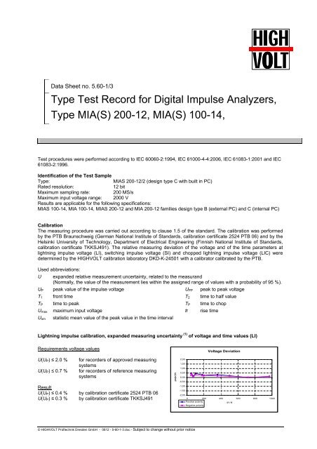
Lightning impulse calibration, expanded measuring uncertainty (1) of voltage and time values (LI)<br />
Requirements voltage values<br />
U(UP) ≤ 2.0 % <strong>for</strong> recorders of approved measuring<br />
systems<br />
U(UP) ≤ 0.7 % <strong>for</strong> recorders of reference measuring<br />
systems<br />
Result<br />
U(UP) ≤ 0.4 % by calibration certificate 2524 PTB 06<br />
U(UP) ≤ 0.3 % by calibration certificate TKKSJ491<br />
© HIGHVOLT Prüftechnik Dresden GmbH - 0812 - 5-60-1-3.doc - Subject to change without prior notice<br />
δm(U)/%<br />
2,00<br />
1,50<br />
1,00<br />
0,50<br />
0,00<br />
-0,50<br />
-1,00<br />
-1,50<br />
-2,00<br />
Voltage Deviation<br />
0 200 400 600 800 1000<br />
Positive polarity<br />
Negative polarity<br />
U / V
Requirements time values<br />
U(T1,T2) ≤ 4.0 % <strong>for</strong> recorders of approved measuring<br />
systems<br />
U(T1,T2) ≤ 3.0 % <strong>for</strong> recorders of reference measuring<br />
systems<br />
Result<br />
U(T1,T2) ≤ 1.5 % by calibration certificate 2524 PTB 06<br />
U(T1,T2) ≤ 1.4 % by calibration certificate TKKSJ491<br />
Switching impulse calibration, expanded measuring uncertainty (1) of voltage and time values (SI)<br />
Requirements voltage values<br />
U(UP) ≤ 2.0 % <strong>for</strong> recorders of approved measuring systems<br />
U(UP) ≤ 0.7 % <strong>for</strong> recorders of reference measuring systems<br />
Result<br />
U(UP) ≤ 0.4 % by calibration certificate 2524 PTB 06<br />
U(UP) ≤ 0.2 % by calibration certificate TKKSJ491<br />
Requirements time values<br />
U(TP,T2) ≤ 4.0 % <strong>for</strong> recorders of approved measuring<br />
systems<br />
U(TP,T2) ≤ 3.0 % <strong>for</strong> recorders of reference measuring<br />
systems<br />
Result<br />
U(TP,T2) ≤ 1.5 % by calibration certificate 2524 PTB 06<br />
U(TP,T2) ≤ 1.0 % by calibration certificate TKKSJ491<br />
Front chopped lightning impulse calibration, expanded measuring uncertainty (1) of voltage and time values<br />
(LIC)<br />
Requirements voltage values<br />
U(UP) ≤ 3.0 % <strong>for</strong> recorders of approved measuring systems<br />
U(UP) ≤ 2.0 % <strong>for</strong> recorders of reference measuring systems<br />
Result<br />
U(UP) ≤ 0.6 % by calibration certificate 2524 PTB 06<br />
Requirements time values<br />
U(TC) ≤ 4.0 % <strong>for</strong> recorders of approved measuring<br />
systems<br />
U(TC) ≤ 3.0 % <strong>for</strong> recorders of reference measuring<br />
systems<br />
Result<br />
U(TC) ≤ 1.5 % by calibration certificate 2524 PTB 06<br />
© HIGHVOLT Prüftechnik Dresden GmbH - 0812 - 5-60-1-3.doc - Subject to change without prior notice<br />
δm(T)/%<br />
3,00<br />
2,00<br />
1,00<br />
0,00<br />
-1,00<br />
-2,00<br />
Time Deviation<br />
-3,00<br />
0,00 200,00 400,00 600,00 800,00 1000,00<br />
T1, positive polarity T1, negative polarity<br />
U / V<br />
T2, positive polarity T2, negative polarity<br />
δm(U)/%<br />
δm(U)/%<br />
δm(T)/%<br />
δm(T)/%<br />
1,00<br />
0,80<br />
0,60<br />
0,40<br />
0,20<br />
0,00<br />
-0,20<br />
-0,40<br />
-0,60<br />
-0,80<br />
-1,00<br />
Voltage Deviation<br />
0 100 200 300 400 500 600 700 800 900 1000<br />
Positive polarity<br />
Negative polarity<br />
U / V<br />
2,00<br />
1,50<br />
1,00<br />
0,50<br />
0,00<br />
-0,50<br />
-1,00<br />
-1,50<br />
-2,00<br />
1,50<br />
1,00<br />
0,50<br />
0,00<br />
-0,50<br />
-1,00<br />
-1,50<br />
4,00<br />
3,00<br />
2,00<br />
1,00<br />
0,00<br />
-1,00<br />
-2,00<br />
-3,00<br />
Time Deviation<br />
0 100 200 300 400 500 600 700 800 900 1000<br />
Tp, positive polarity Tp, negative polarity<br />
U / V<br />
T2, positive polarity T2, negative polarity<br />
Voltage Deviation<br />
0 100 200 300 400<br />
U / V<br />
500 600 700 800<br />
Positive polarity<br />
Negative polarity<br />
Time Deviation<br />
-4,00<br />
0 100 200 300 400 500 600 700 800<br />
TC, positive polarity<br />
TC, negative polarity<br />
U / V
Step calibration, expanded measuring uncertainty (1) of voltage values (STEP)<br />
Requirements voltage values<br />
U(Usm) ≤ 1.0 % <strong>for</strong> recorders of approved measuring<br />
systems<br />
U(Usm) ≤ 0.5 % <strong>for</strong> recorders of reference measuring<br />
systems<br />
Result<br />
U(Usm) ≤ 0.30 % by 2524 PTB 06<br />
(1) The expanded measuring uncertainty is the parameter requested by IEC 60060-2 and IEC61083-1. It shall be mentioned that it<br />
includes all measuring conditions. Consequently, it is larger than the single deviation given in the diagrams.<br />
Software <strong>Test</strong><br />
The comprehensive software test according to IEC 61083-2 <strong>for</strong> checking all the operations was per<strong>for</strong>med successfully.<br />
This includes the recording of different impulses (LI, LIC, SI, Step), the functionality of the coordinate system, the creating<br />
of the protocol and the execution of the self test. Based on this, the curves according to IEC 61083-2 were loaded,<br />
evaluated and saved. The results were compared with the limits of the instruction. All impulse shapes are within the limits.<br />
IEC curve measured value limits measured value limits measured value limits<br />
No. 1 (LI) UP [MV] 1.050 1.04 … 1.06 T1 [ns] 846.7 810 … 870 T2 [µs] 60.01 57.5.. .62.5<br />
No. 2 (LIC) UP [kV] 861.0 860 … 880 T1 [ns] 494.5 490 … 530 TC [ns] 567.6 550 … 590<br />
No. 3 (LI) UP [MV] 1.049 1.04 … 1.06 T1 [µs] 1.661 1.6 … 1.7 T2 [µs] 46.80 45 … 49<br />
No. 4 (LI) UP [kV] 975.8 960 … 990 T1 [µs] 1.053 1.0 … 1.1 T2 [µs] 49.67 48 … 52<br />
No. 5 (SI) UP [kV] 950.4 940 … 960 TP [µs] 248.9 240 … 260 T2 [ms] 2.503 2.4 … 2.6<br />
No. 6 (LI) UP [MV] 1.053 1.04 … 1.06 T1 [ns] 849.4 810 … 870 T2 [µs] 59.81 57.5 62.5<br />
No. 7 (LIC) UP [MV] 1.050 1.04 1.06 T1 [ns] 497.7 490 … 530 TC [ns] 566.4 550 ..590<br />
No. 8 (LI) UP [MV] 1.050 1.04 1.06 T1 [µs] 1.662 1.6 … 1.7 T2 [µs] 46.84 45 … 49<br />
No. 9 (LI) UP [kV] 972.9 960 … 990 T1 [µs] 1.047 1.0 … 1.1 T2 [µs] 49.49 48 … 52<br />
No. 10 (SI) UP [kV] 947.3 940 … 960 TP [µs] 254.2 240 … 260 T2 [ms] 2.493 2.4 … 2.6<br />
No. 11 (LI) UP [kV] 956.2 940 … 960 T1 [µs] 1.100 1.07 1.19 T2 [µs] 86.99 82 … 91<br />
No.12 (LIC) UP [kV] 847.5 840 … 870 T1 [ns] 528.5 480 540 TC [ns] 557.6 510 … 560<br />
No. 13 (LI) UP [MV] -1.07 -1.08..-1.06 T1 [µs] 3.430 3.40 3.76 T2 [µs] 60.42 56 … 62<br />
No. 14 (LI) UP [kV] -965. -970 -950 T1 [µs] 1.926 1.85… 2.05 T2 [µs] 45.13 43 … 47<br />
Time Base<br />
The measuring procedure was carried out according to clause 1.5.4 of the standard IEC 61083-1.<br />
<strong>Test</strong> signal: rectangular<br />
UPP = 5 V<br />
f = 50 Hz<br />
The time between the slope of the first cycle and the slope of the second cycle has been measured <strong>for</strong> one period. The<br />
time base deviation related to the optimum value of the cycle duration (T = 20 ms) and its standard deviation has been<br />
determined by the measured values.<br />
Requirements Results<br />
Time base deviation: ≤ ± 0.2 % Time base deviation: ≤ 0.003 %<br />
Standard deviation: ≤ ± 0.1 % Standard deviation: ≤ 0.001 %<br />
© HIGHVOLT Prüftechnik Dresden GmbH - 0812 - 5-60-1-3.doc - Subject to change without prior notice<br />
δm(U)/%<br />
Voltage Deviation<br />
1,00<br />
1,50<br />
0,80<br />
0,60 1,00<br />
0,40<br />
0,50<br />
0,20<br />
0,00 0,00<br />
-0,20<br />
-0,50<br />
-0,40<br />
-0,60<br />
-1,00<br />
-0,80<br />
-1,00 -1,50<br />
0 0 100200 200 300 400 400<br />
U / V<br />
600 500 600 800700 800 1000<br />
Positive polarity<br />
Negative polarity
Rise Time<br />
The measuring procedure has been carried out according to clause 1.5.5 of the standard IEC 61083-1.<br />
<strong>Test</strong> signal: step impulse<br />
Measured with Tektronix TDS5054<br />
• input of internal divider tr = 1.3 ns<br />
• output of internal divider tr ≤ 1.8 ns<br />
Measured with <strong>MIA</strong>S 200-12/2<br />
Sampling rate: 2GS/s (random interleaved sampling)<br />
The rise and fall time are measured with different values<br />
of the voltage.<br />
Requirements<br />
Rise time tr ≤ 15 ns (8.75 ns)<br />
Result<br />
tr = 2.75 ns<br />
Noise Level<br />
The measuring procedure was carried out according to<br />
clause 1.5.9.1 of the standard IEC 61083-1.<br />
<strong>Test</strong> signal: sine<br />
UPP = 1 V<br />
f = 9.83 MHz<br />
Requirements<br />
Noise level average ≤ 0.1 %<br />
Result<br />
Noise level average ≤ 0.001%<br />
Interference<br />
The measuring procedure was carried out according to clause 1.5.10 of the standard IEC 61083-1.<br />
Moreover, the crosstalk of two channels was tested. The test signal was connected to one channel.<br />
The second channel has been hot-wired. The FFT has been calculated and compared <strong>for</strong> both curves.<br />
Requirements Result<br />
Interference ≤ 1% Interference ≤ 0.1%<br />
Electromagnetic Compatibility (EMC)<br />
The measuring procedure has been carried out according to Annex B of the standard, per<strong>for</strong>med and certified at<br />
TU Dresden / GWT.<br />
The EMC was tested regarding to:<br />
• Emitted interference<br />
This test is divided in: - Conducted emission<br />
- Rayed emission<br />
- Electromagnetic shielding<br />
• Electrostatic discharge (ESD)<br />
• High frequency fields (HF-fields)<br />
• Burst immunity test (level 3)<br />
• High frequency asymmetric<br />
© HIGHVOLT Prüftechnik Dresden GmbH - 0812 - 5-60-1-3.doc - Subject to change without prior notice
Summary of the <strong>Test</strong><br />
During these tests no defects were observed. The digital impulse analyzer fulfils all requirements of IEC 61083-1<br />
and IEC 61000-4-4.<br />
Voltage Drop<br />
The measuring procedure was carried out according to Annex B of the standard IEC 61083-1.<br />
<strong>Test</strong> conditions<br />
Duration of breaks: 0.5; 5; 50; 250 cycles<br />
Duration of tests: 5 breaks<br />
During the voltage drop of 0.5 and 5 cycles no failures were registered. After the voltage drop of 50 and 250 cycles<br />
the internal computer restarted and the connection <strong>for</strong> operating could be recovered. The test was passed.<br />
Surge Voltage<br />
- Input Voltage (Umax): 1000 V and 2000 V<br />
- <strong>Test</strong> signal<br />
Pulse <strong>for</strong>m: LI, LIC<br />
- Voltages: 1 · Umax, 2 · Umax, 2.5 · Umax, 3 · Umax, 3.5 · Umax, 4 · Umax<br />
Two different input dividers were tested. At channel 1 the surge voltage has been impressed and at channel 2 this<br />
voltage has been controlled. The stressed channel has measured the voltage up to the limit of the measurement<br />
range.<br />
When the voltage fell below the limit of the measurement range the values have been recorded without any time<br />
lag. The test objects have passed the test successfully in all voltage levels.<br />
Static integral non-linearity (INL)<br />
The measuring procedure has been carried out<br />
according to clause 1.5.7 of the standard.<br />
Requirements<br />
INL ≤ ± 0.5 %<br />
Result<br />
INL ≤ ± 0.025%<br />
Static differential non-linearity (DNL)<br />
The measuring procedure has been carried out<br />
according to clause 1.5.7 of the standard.<br />
Requirements<br />
DNL ≤ ± 0.8 %<br />
Result<br />
DNL ≤ ± 0.2 %<br />
© HIGHVOLT Prüftechnik Dresden GmbH - 0812 - 5-60-1-3.doc - Subject to change without prior notice
Dynamic differential non-linearity (DDNL)<br />
The measuring procedure has been carried out<br />
according to clauses 1.5.8 of the standard<br />
IEC 61083-1<br />
Requirements<br />
DDNL ≤ ±0.8 %<br />
Result<br />
DDNL ≤ ± 0.2 %<br />
For further in<strong>for</strong>mation please contact: or our local representative:<br />
HIGHVOLT Prüftechnik Dresden GmbH<br />
Marie-Curie-Strasse 10<br />
D-01139 Dresden / Germany<br />
Tel. +49 351 8425-648<br />
Fax +49 351 8425-679<br />
e-mail dresden@highvolt.de<br />
website http://www.highvolt.de<br />
© HIGHVOLT Prüftechnik Dresden GmbH - 0812 - 5-60-1-3.doc - Subject to change without prior notice