150H Fork Positioner - Cascade Corporation
150H Fork Positioner - Cascade Corporation
150H Fork Positioner - Cascade Corporation

You also want an ePaper? Increase the reach of your titles
YUMPU automatically turns print PDFs into web optimized ePapers that Google loves.
S<br />
ERVICE MANUAL<br />
<strong>150H</strong> <strong>Fork</strong> <strong>Positioner</strong><br />
Manual Number 219473 R-1<br />
cascade�<br />
corporation<br />
<strong>Cascade</strong> is a Registered Trademark of <strong>Cascade</strong> <strong>Corporation</strong>
C<br />
ONTENTS<br />
Page<br />
INTRODUCTION, Section 1<br />
Introduction, 1.1 1<br />
Special Definitions, 1.2 1<br />
INSTALLATION, Section 2<br />
Truck System Requirements, 2.1 2<br />
Recommended Hydraulic Supply Options, 2.2 3<br />
Installation Procedure, 2.3 4<br />
PERIODIC MAINTENANCE, Section 3<br />
100-Hour Maintenance, 3.1 11<br />
500-Hour Maintenance, 3.2 11<br />
1000-Hour Maintenance, 3.3 11<br />
2000-Hour Maintenance, 3.4 11<br />
TROUBLESHOOTING, Section 4<br />
General Procedures, 4.1 12<br />
Truck System Requirements, 4.1-1 12<br />
Tools Required, 4.1-2 12<br />
Troubleshooting Chart, 4.1-3 12<br />
Plumbing, 4.2 13<br />
Hosing Diagram, 4.2-1 13<br />
Hydraulic Circuit Schematic, 4.2-2 13<br />
<strong>Fork</strong> Position Function, 4.3 14<br />
Supply Circuit Test, 4.3-1 14<br />
<strong>Fork</strong> Position Circuit Test, 4.3-2 14<br />
Sideshift Function, 4.4 15<br />
Supply Circuit Test, 4.4-1 15<br />
Sideshift Circuit Test, 4.4-2 15<br />
Electrical Circuit, 4.5 16<br />
Page<br />
SERVICE, Section 5<br />
5.1 <strong>Fork</strong> <strong>Positioner</strong> Removal 17<br />
5.2 Valve 18<br />
5.2-1 Removal 18<br />
5.2-2 Valve Service 18<br />
5.3 Cylinders 19<br />
5.3-1 Cylinder Removal 19<br />
5.3-2 Cylinder Disassembly 20<br />
5.3-3 Cylinder Inspection 20<br />
5.3-4 Cylinder Reassembly 21<br />
5.4 <strong>Fork</strong> Carriers 21<br />
5.4-1 <strong>Fork</strong> Carrier Bushings<br />
SPECIFICATIONS, Section 6<br />
21<br />
6.1 Specifications 22<br />
6.1-1 Hydraulics 22<br />
6.1-2 Auxiliary Valve Functions 22<br />
6.1-3 Truck Carriage 22<br />
6.1.4 Torque Values 23<br />
i 219473 Rev. 1
I<br />
NTRODUCTION<br />
1.1 Introduction<br />
This Manual provides the Installation, Periodic Maintenance,<br />
Troubleshooting, Service and Specifications for<br />
<strong>Cascade</strong> <strong>150H</strong> <strong>Fork</strong> <strong>Positioner</strong> with D-Series Sideshifter.<br />
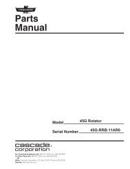
In any communication about the <strong>Fork</strong> <strong>Positioner</strong>, refer to<br />
the product I.D. number stamped on the nameplate as<br />
shown. If the nameplate is missing, the numbers can be<br />
found stamped on the back of the baseplate.<br />
IMPORTANT: All hoses, tubes and fittings on H-Series<br />
<strong>Fork</strong> <strong>Positioner</strong>s are JIC.<br />
NOTE: Specifications are shown<br />
in both U.S. and (Metric) units.<br />
Nameplate<br />
1.2 Special Definitions<br />
The statements shown appear throughout this Manual<br />
where special emphasis is required. Read all WARNINGS<br />
and CAUTIONS before proceeding with any work.<br />
Statements labeled IMPORTANT and NOTE are provided<br />
as additional information of special significance or to<br />
make the job easier.<br />
WARNING - A statement preceded by<br />
WARNING is information that should be<br />
acted upon to prevent bodily injury. A<br />
WARNING is always inside a ruled box.<br />
CAUTION - A statement preceded by CAUTION is<br />
information that should be acted upon to prevent<br />
machine damage.<br />
FP0440.ill<br />
IMPORTANT - A statement preceded by IMPORTANT is<br />
information that possesses special significance.<br />
NOTE - A statement preceded by NOTE is information<br />
that is handy to know and may make the job easier.<br />
c<br />
SERIAL<br />
NUMBER<br />
CATALOG<br />
NUMBER<br />
ADDITIONAL<br />
EQUIPMENT<br />
ADDITIONAL<br />
EQUIPMENT<br />
ADDITIONAL<br />
EQUIPMENT<br />
cascade<br />
�<br />
���� ����� ����������<br />
������������<br />
ATTACHMENT CAPACITY<br />
FOR TECHNICAL ASSISTANCE, PARTS AND SERVICE<br />
CONTACT:<br />
1-800-227–2233<br />
PORTLAND, OREGON USA<br />
219473 Rev. 1 1<br />
WEIGHT<br />
LBS.<br />
POUNDS<br />
AT<br />
INCH LOAD<br />
CENTER<br />
CAPACITY OF TRUCK AND ATTACHMENT COMBINATION<br />
MAY BE LESS THAN ATTACHMENT CAPACITY SHOWN<br />
ABOVE. CONSULT TRUCK NAMEPLATE.<br />
RECOMMENDED SYSTEM PRESSURE – 2000 PSI<br />
MAXIMUM SYSTEM PRESSURE – 2300 PSI<br />
cascade�<br />
S/N <strong>150H</strong>-FPB-005
I<br />
NSTALLATION<br />
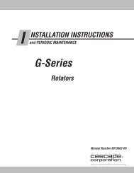
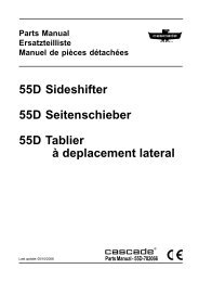
2.1 Truck System<br />
Requirements<br />
The <strong>150H</strong> <strong>Fork</strong> <strong>Positioner</strong> will provide maximum operating<br />
capability when the following requirements are met.<br />
A<br />
Truck Relief Setting<br />
GA0028.ill<br />
2300 psi (160 bar) Recommended<br />
2600 psi (180 bar) Maximum<br />
Truck Flow Volume ➀<br />
<strong>150H</strong> Min. ➁ Recommended Max. ➂<br />
<strong>Fork</strong><br />
3 GPM 4 GPM 5 GPM<br />
Position<br />
(11 L/min.) (15 L/min.) (19 L/min.)<br />
Sideshift<br />
1 GPM<br />
(4 L/min.)<br />
6 GPM<br />
(23 L/min.)<br />
12 GPM<br />
(45 L/min.)<br />
➀ <strong>Cascade</strong> H-Series <strong>Fork</strong> <strong>Positioner</strong>s are compatible with SAE<br />
10W petroleum base hydraulic fluid meeting Mil. Spec. MIL-0-<br />
5606 or MIL-0-2104B. Use of synthetic or aqueous base<br />
hydraulic fluid is not recommended. If fire resistant hydraulic<br />
fluid is required, special seals must be used. Contact <strong>Cascade</strong>.<br />
➁ Flow less than recommended can result in slow and unequal<br />
fork movement.<br />
➂ Flow greater than maximum can result in excessive heating,<br />
reduced system performance and short hydraulic system life.<br />
Carriage Mount Dimension (A) ITA (ISO)<br />
Auxiliary Valve Functions<br />
Check for compliance with ANSI standards:<br />
GA0082.ill<br />
Minimum Maximum<br />
Class IV 23.44 in. (595.5 mm) 23.50 in. (597.0 mm)<br />
Hoist Down<br />
Hoist Up<br />
Tilt<br />
Back<br />
Tilt<br />
Forward<br />
Sideshift<br />
Left<br />
Sideshift<br />
Right<br />
Spread<br />
<strong>Fork</strong>s<br />
Close<br />
<strong>Fork</strong>s<br />
WARNING: Rated capacity of the truck/<br />
attachment combination is a responsibility of<br />
the original truck manufacturer and may be<br />
less than that shown on the attachment<br />
nameplate. Consult the truck nameplate.<br />
GA0095.ill<br />
Carriage – Clean and inspect carriage<br />
bars. Assure that bars are parallel and<br />
ends are flush. Grind smooth any protruding<br />
welds that may affect Sideshifter lower<br />
bearings. Repair any damaged notches.<br />
2 219473 Rev. 1
I<br />
NSTALLATION<br />
2.2 Recommended<br />
Hydraulic Supply<br />
Options<br />
H-Series <strong>Fork</strong> <strong>Positioner</strong>s can be operated with any of<br />
the hydraulic supply arrangements shown below.<br />
Refer to <strong>Cascade</strong> Hose and Cable Reel Selection<br />
Guide, Part No. 212119, to select the correct hose<br />
reel for the mast and truck. Hose and fitting requirements<br />
are as follows:<br />
• All hoses and fittings for the fork-positioning and<br />
sideshifting (if equipped) functions should be No. 6<br />
with 9/32 in. (7 mm) minimum I.D.<br />
B<br />
GA0033.ill<br />
Non-Sideshifting<br />
A Mast Single Internal Reeving<br />
OR<br />
C LH THINLINE� 2-Port Hose Reel Group<br />
Sideshifting<br />
A Mast Double Internal Reeving<br />
OR<br />
A and C Mast Single Internal Reeving and<br />
LH THINLINE� 2-Port Hose Reel<br />
Group<br />
OR<br />
B and C RH and LH THINLINE� 2-Port Hose<br />
Reel Groups<br />
Solenoid Adaption<br />
A and B Mast Single Internal Reeving and<br />
RH Cable Reel Group<br />
OR<br />
B RH 6-N-1 Cable/Hose Reel Group<br />
219473 Rev. 1 3<br />
C<br />
A
I<br />
NSTALLATION<br />
2.3 Installation Procedure<br />
Follow the steps shown to install the <strong>Fork</strong> <strong>Positioner</strong> on the<br />
truck. Read and understand all WARNINGS and CAUTION<br />
statements. If you don't understand a procedure, ask your<br />
supervisor, or call the nearest <strong>Cascade</strong> Service Department<br />
for assistance.<br />
1<br />
2 Unlock<br />
Attach overhead hoist<br />
A Remove banding.<br />
B Attach hoist to top of backrest as shown and<br />
lift Attachment into vertical position.<br />
C Remove bolt-on lower mounting hooks.<br />
B<br />
C<br />
quick-change lower<br />
mounting hooks (if equipped)<br />
A Remove pin and drop hooks into<br />
unlocked position.<br />
B Reinstall pin in lower hole.<br />
Guide<br />
Pin<br />
cascade ®<br />
C-675514-1<br />
A<br />
LH lower<br />
Hook<br />
5/8-in. (16 mm)<br />
offset on top<br />
provides max.<br />
clearance.<br />
WARNING: Make sure overhead hoist<br />
has a rated capacity of at least<br />
2000 lbs. (910 kg.)<br />
4 219473 Rev. 1<br />
B<br />
FP0263.ill<br />
NOTE: Guides can be reversed to<br />
change hook-to-carriage clearance<br />
(See lower hook installation, Step 4).<br />
CL0097.ill<br />
Tighten Capscrews:<br />
Class II, III Mounting – 165 ft.-lbs. (225 Nm)<br />
Class IV Mounting – 190 ft.-lbs. (255 Nm)
I<br />
3 Mount<br />
NSTALLATION<br />
<strong>Fork</strong> <strong>Positioner</strong> on truck<br />
A Lower Attachment onto truck carriage.<br />
B Engage upper mounting hooks. If<br />
sideshifter equipped (shown), make sure<br />
bearings are in place and centering tab<br />
engages center notch on truck carriage.<br />
ITA Class IV – 0.72–0.78 in. (18–20 mm)<br />
ITA Class IV – 0.47–0.51 in. (12–13 mm)<br />
4 Install<br />
or engage lower hooks<br />
Tap tight into position.<br />
If sideshifter, back off<br />
1 notch and check<br />
clearance:<br />
3/32 in. (2.4 mm) min.<br />
3/16 in. (4.8 mm) max.<br />
219473 Rev. 1 5<br />
FP0209.ill<br />
BOLT-ON TYPE QUICK-CHANGE TYPE<br />
(optional)<br />
������<br />
Center<br />
Notch<br />
Truck<br />
Carriage<br />
Tighten Capscrews:<br />
Class IV Mounting – 190 ft.-lbs. (255 Nm)<br />
Lower<br />
Carriage<br />
Bar<br />
SS0140.ill<br />
SS0139.ill<br />
Back (Driver's) View<br />
Slide hook up<br />
to engage<br />
bar, install<br />
pin in locked<br />
position.<br />
(upper hole.)<br />
A<br />
cascade �<br />
����������<br />
B<br />
Sideshifter<br />
Upper Bearings<br />
Lower<br />
Carriage<br />
Bar<br />
SS0141.ill<br />
FP0651.ill<br />
Inspect hooks for<br />
excessive clearance.<br />
(Reverse<br />
guides to reduce<br />
clearance – see<br />
Step 2.)<br />
3/16 in.<br />
(4.8 mm)<br />
max.
I<br />
5<br />
NSTALLATION<br />
Install <strong>Fork</strong>s<br />
A Attach overhead hoist to backrest as shown.<br />
B Remove capscrews fastening <strong>Fork</strong> <strong>Positioner</strong><br />
frame to sideshifter or false carriage. Raise<br />
frame to install forks.<br />
WARNING: Assure locking pins<br />
are removed from forks. <strong>Fork</strong>s<br />
must slide freely on carriage bars.<br />
C Install forks, using bottom fork slot to engage<br />
forks with carriage.<br />
D Line up forks with fork carriers on frame.<br />
E Reinstall frame, engaging fork carriers with<br />
forks and top carriage bar. Tighten mounting<br />
capscrews to 115–125 ft.-lbs. (155–170 Nm).<br />
<strong>Fork</strong> Carriers<br />
FP0210.ill<br />
<strong>Fork</strong> <strong>Positioner</strong> Frame<br />
D<br />
Sideshifter or<br />
False Carriage<br />
Mounting Capscrews (4).<br />
6 219473 Rev. 1<br />
A<br />
C<br />
<strong>Fork</strong>s<br />
B
I<br />
6<br />
NSTALLATION<br />
Prepare hoses<br />
A Determine hose lengths required for<br />
hydraulic supply configuration of truck.<br />
B Cut hoses to length and install end fittings<br />
or quick-disconnect kits.<br />
INTERNAL HOSE REEVING<br />
Sideshifting / Non-sideshifting<br />
Close <strong>Fork</strong>s Close <strong>Fork</strong>s<br />
Spread <strong>Fork</strong>s Spread <strong>Fork</strong>s<br />
7 Flush<br />
Sideshift Right Sideshift Left<br />
FP0207.ill<br />
hydraulic supply hoses<br />
A Install hoses to hose terminals on carriage.<br />
Connect together using union fittings.<br />
B Operate auxiliary valves for 30 sec.<br />
C Remove union fittings.<br />
Back (Driver's) View<br />
HOSE REELS<br />
Sideshifting / Non-Sideshifting<br />
Sideshift Right Sideshift Left<br />
GA0092.ill<br />
219473 Rev. 1 7<br />
FP0208.ill
I NSTALLATION<br />
8 Connect<br />
9 Install<br />
Plate<br />
Button<br />
toward<br />
driver<br />
10<br />
hoses prepared in<br />
Step 6 to Attachment fittings<br />
solenoid control knob or<br />
pushbutton switch (solenoid equipped)<br />
FP0624.ill<br />
Nut<br />
Install wiring –<br />
(Solenoid equipped units)<br />
7.5-Amp Fuse<br />
White<br />
Knob<br />
Button<br />
Black<br />
Snap Ring<br />
Adapter<br />
Diode<br />
PRESS<br />
BUTTON<br />
TO POSITION<br />
SIDESHIFT<br />
SIDESHIFT Control Lever<br />
Solenoid Coil<br />
7.5-Amp<br />
Fuse<br />
CL0258.ill CL0257.ill<br />
Control Lever Knob<br />
White Black<br />
User-supplied wire<br />
Solenoid Coil<br />
8 219473 Rev. 1<br />
Cable<br />
Ties<br />
Foam Tape<br />
Pushbutton<br />
Switch<br />
Heat Shrink Tubing<br />
Diode<br />
AC0898.ill<br />
FP0219.ill<br />
NOTE: Shrink tubing<br />
may be removed around<br />
button as desired.<br />
3 in. (60 mm)<br />
Typical
I NSTALLATION<br />
11<br />
Cycle <strong>Fork</strong> <strong>Positioner</strong> functions<br />
NON-SIDESHIFTING<br />
A Spread <strong>Fork</strong>s<br />
B Close <strong>Fork</strong>s<br />
C (not used)<br />
D (not used)<br />
B<br />
A<br />
• Spread forks and close forks several times.<br />
Sideshift (if equipped) left and right. Check<br />
for smoothness and equal movement.<br />
• Check for operation in accordance with ITA<br />
(ISO) standards.<br />
• Check for leaks at fittings, valve, cylinders.<br />
B<br />
FP0164.ill<br />
A<br />
B<br />
D<br />
GA0005.ill<br />
SIDESHIFTING<br />
A Sideshift Left<br />
B Sideshift Right<br />
C Spread <strong>Fork</strong>s<br />
D Close <strong>Fork</strong>s<br />
C<br />
Hoist down<br />
Hoist up<br />
219473 Rev. 1 9<br />
A<br />
FP0164.ill<br />
AUXILIARY VALVE FUNCTIONS<br />
D<br />
A<br />
Tilt back<br />
C<br />
Tilt forward<br />
C<br />
B D<br />
SIDESHIFTING WITH<br />
SOLENOID VALVE<br />
A Sideshift Left<br />
A Spread <strong>Fork</strong>s<br />
(press knob button)<br />
B Sideshift Right<br />
B Close <strong>Fork</strong>s<br />
(press knob button)<br />
B<br />
B<br />
A<br />
A<br />
B<br />
FP0164.ill<br />
A
I NSTALLATION<br />
12<br />
13<br />
Adjust forks for equal movement<br />
(if required)<br />
NOTE: Attachment is Factory-adjusted for<br />
equal fork movement when operated at<br />
recommended pressure and flow rate at<br />
normal operating temperature.<br />
A Locate the flow restrictor fittings below the<br />
valve. Loosen jam nuts and screw both<br />
flow restrictors in until they bottom. Screw<br />
each restrictor out (CCW) three turns.<br />
B Cycle forks open and closed five (5) times<br />
to warm up hydraulic system. Look for<br />
unequal fork movement.<br />
C On faster fork (one that bottoms first),<br />
screw flow restrictor in (CW) 1/2-turn.<br />
D Repeat Steps B and C until fork movement<br />
is equal. Tighten jam nuts.<br />
Inspect fork hooks and<br />
carriage bar clearance<br />
NOTE: Use go/no-go Wear Gauge Part No.<br />
209560 (Class II) or 209561 (Class III).<br />
A Inspect the fork lower hooks and<br />
carriage bar. If the gauge fits between<br />
the carriage bar and lower hook, repair<br />
or replacement is needed.<br />
B Inspect the upper carriage bar. If the<br />
gauge arrow touches the carriage bar,<br />
repair or replacement is needed.<br />
C Inspect the fork upper hooks. If the<br />
gauge arrow touches the hook, repair<br />
or replacement is needed.<br />
Crossover Relief Valve Cartridges<br />
Front View<br />
10 219473 Rev. 1<br />
OK<br />
A<br />
FP0176.ill<br />
FORK LOWER HOOKS, CARRIAGE<br />
OK<br />
OK<br />
Wear<br />
Gauge<br />
UPPER CARRIAGE BAR<br />
FORK UPPER HOOKS<br />
Flow<br />
Restrictor<br />
Fittings/<br />
Adjuster<br />
Screws<br />
FP0631.ill
P<br />
ERIODIC MAINTENANCE<br />
WARNING: After completing any service<br />
procedure, always test each function<br />
through five complete cycles. First test<br />
with no load, then test with a load to<br />
make sure the attachment operates<br />
correctly before returning it to the job.<br />
3.1 100-Hour Maintenance<br />
Every time the lift truck is serviced or every 100 hours of<br />
truck operation, whichever comes first, perform the following<br />
maintenance procedures:<br />
• Check for loose or missing bolts, worn or damaged<br />
hoses and hydraulic leaks.<br />
3.2 500-Hour Maintenance<br />
After each 500 hours of truck operation, in addition to the<br />
100-hour maintenance, perform the following procedures:<br />
• Tighten frame mounting capscrews (4) to 110 ft.-lbs.<br />
(145 Nm).<br />
• Tighten lower hook capscrews as follows:<br />
Class IV Mounting – 190 ft.-lbs. (255 Nm)<br />
• Apply a molybdenum disulfide grease ('Molykote GN' or<br />
equivalent) to fork carrier grease fittings (2).<br />
• Apply chassis grease to cylinder rod anchors (2).<br />
• Apply chassis grease to sideshifter (if equipped) upper<br />
bearing grease fittings (2), and lower flat bearings (2).<br />
• Check fork hooks and carriage bars for wear using a<br />
wear gauge (<strong>Cascade</strong> Part No. 209560 for Class II,<br />
209661 for Class III). Refer to Section 2, Step 13.<br />
3.3 1000-Hour Maintenance<br />
After each 1000 hours of truck operation, in addition to the<br />
100 and 500-hour maintenance, perform the following<br />
procedures:<br />
• Inspect fork carrier bearings for wear and replace if<br />
necessary.<br />
.<br />
• Inspect fork-positioning cylinder rod anchors for wear<br />
and replace if necessary.<br />
• Inspect thickness of sideshifter (if equipped) upper<br />
bearing sets. If any bearing segment is worn to less<br />
than 1/16-in (1.5 mm) thick, replace all bearings.<br />
• Inspect exposed thickness of lower sideshifter (if<br />
equipped) bearings. If any bearing shows less than<br />
1/16-in. (1.5 mm), replace all bearings.<br />
3.4 2000-Hour Maintenance<br />
After each 2000 hours of truck operation, in addition to the<br />
100, 500, and 1000-hour maintenance, perform the following<br />
procedures:<br />
• Replace fork carrier bearings.<br />
<strong>Fork</strong> Carrier<br />
Grease Fittings (2)<br />
<strong>Fork</strong><br />
Carrier<br />
Bearings<br />
Mounting Capscrews (4)<br />
Front View<br />
Sideshifter<br />
Upper Bearings<br />
Sideshifter<br />
Lower Bearings<br />
Sideshifter Frame<br />
Grease Fittings (2)<br />
(Sideshift to expose fittings)<br />
Cylinder Rod Anchors<br />
Back (Driver's) View<br />
219473 Rev. 1 11<br />
FP0206.ill<br />
FP0205.ill<br />
Lower Hook<br />
Capscrews
T<br />
ROUBLESHOOTING<br />
4.1 General Procedures<br />
4.1-1 Truck System Requirements<br />
• Truck hydraulic pressure should be within the pressure<br />
range as shown in Section 6.1. PRESSURE MUST<br />
NOT EXCEED 2600 psi (180 bar).<br />
• Truck hydraulic flow should be within the volume range<br />
as shown in Section 6.1 .<br />
• Truck hydraulic fluid supplied to the Attachment must<br />
meet the specifications as shown in Section 6.1.<br />
4.1-2 Tools Required (Metric)<br />
In addition to a normal selection of mechanic’s hand<br />
tools, the following are required:<br />
• InLine Flow Meter Kit:<br />
10 GPM (37 L/min.) – <strong>Cascade</strong> Part No. 671476.<br />
20 GPM (75 L/min.) – <strong>Cascade</strong> Part No. 671477.<br />
• Pressure Gauge Kit:<br />
5000 psi (345 bar) – <strong>Cascade</strong> Part No. 671212<br />
• Assorted fittings, lines, drain hoses and quick-couplers<br />
as required.<br />
4.1-3 Troubleshooting Chart –<br />
<strong>150H</strong> <strong>Fork</strong> <strong>Positioner</strong><br />
Determine All The Facts – It is important to gather all the<br />
facts about the problem before beginning any service<br />
procedures. The first step is to talk to the equipment<br />
operator. Ask for a complete description of the malfunction.<br />
Guidelines below can then be used as a starting<br />
point to begin troubleshooting.<br />
• <strong>Fork</strong>s open and close unevenly.<br />
• <strong>Fork</strong>s will not open or close.<br />
To correct these problems, see Section 4.3.<br />
• Attachment sideshifts too fast or too slow<br />
• Attachment will not sideshift.<br />
To correct these problems, see Section 4.4.<br />
WARNING: Before servicing any hydraulic<br />
component, relieve pressure in the system.<br />
Turn the truck off and move the truck<br />
auxiliary control valves several times in<br />
both directions.<br />
After completing any service procedure, always test<br />
the Attachment through several cycles. First test the<br />
Attachment empty to bleed any air trapped in the<br />
system to the truck tank. Then test the Attachment<br />
with a load to be sure it operates correctly before<br />
returning to the job.<br />
Stay clear of the load while testing. Do not raise the<br />
load more than 4 in. (10 cm) off the floor while testing.<br />
Flow Meter Kit: 671476 (10 GPM - 37 L/min)<br />
671477 (20 GPM - 75 L/min)<br />
(2) No. 8-12 JIC/<br />
O-Ring<br />
(2) No. 6-8 JIC Reducer<br />
Pressure Gauge Kit 671212<br />
Pressure<br />
Gauge*<br />
No. 4-6 Pipe/JIC*<br />
Female JIC Thread<br />
Coupler:<br />
No. 4 (Part No. 210385)*<br />
No. 6 (Part No. 678591)<br />
No. 6-6 Hose*<br />
GA0014.ill<br />
No. 6-8 JIC<br />
Reducer<br />
Quick-Disconnects<br />
AC0127.ill<br />
* NOTE: Diagnostics Kit 394382<br />
includes items marked.<br />
Flow Meter<br />
GA0013.ill<br />
No. 6 and No. 8<br />
JIC Swivel Tee<br />
No. 4, No. 6*<br />
and No. 8<br />
JIC/O-Ring<br />
Male Straight Thread<br />
O-Ring Coupler:<br />
No. 4 (Part No. 212282)*<br />
No. 5 (Part No. 210378)<br />
No. 6 (Part No. 678592)<br />
12 219473 Rev. 1
T ROUBLESHOOTING<br />
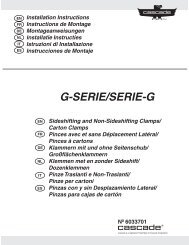
4.2 Plumbing<br />
4.2-1 Hosing Diagram<br />
Pressure:<br />
Return:<br />
SIDESHIFT LEFT, SIDESHIFT RIGHT,<br />
CLOSE FORKS SPREAD FORKS<br />
4.2-2 Hydraulic Schematic<br />
<strong>Fork</strong> Positioning<br />
Cylinders (2)<br />
SSR<br />
Truck Auxiliary<br />
Valve (Sideshift)<br />
Truck Pump<br />
Flow Restrictors<br />
Sideshift Cylinder<br />
SSL<br />
OPEN<br />
(1)<br />
IHR<br />
Terminals<br />
Truck Relief<br />
Valve<br />
Manifold<br />
FP0162.ill<br />
Attachment Valve<br />
Cross-Over<br />
Relief Valves<br />
CLOSE<br />
(2)<br />
Truck Auxiliary<br />
Valve (<strong>Fork</strong> Position)<br />
Truck Tank<br />
Sideshift<br />
Cylinder<br />
Truck<br />
Auxiliary<br />
Valves<br />
219473 Rev. 1 13<br />
OPEN<br />
(1)<br />
CLOSE<br />
(2)<br />
Manifold<br />
FP0161.ill<br />
<strong>Fork</strong><br />
Positioning<br />
Cylinders (2)
T ROUBLESHOOTING<br />
4.3 <strong>Fork</strong> Position<br />
Function<br />
There are five potential problems that could affect the fork<br />
positioning function:<br />
• <strong>Fork</strong>s or fork carriers binding in carriage grooves.<br />
• Incorrect hydraulic pressure or flow to the Attachment.<br />
• External leaks.<br />
• Loose electrical connections or defective solenoid<br />
coil or valve (if equipped).<br />
• Worn/defective cartridge valves or cylinder seals.<br />
4.3-1 Supply Circuit Test<br />
1 Check the truck pressure at the carriage hose terminal.<br />
Pressure must be within 100 psi (7 bar) of that<br />
specified in the truck service manual. TRUCK PRES-<br />
SURE MUST NOT EXCEED 2600 PSI (180 BAR). See<br />
Section 6.1 for recommended operating pressure.<br />
2 Check the flow volume at the carriage hose terminal.<br />
See Section 6.1 for recommended flow volume.<br />
3 Spread the forks fully and hold the lever in the OPEN<br />
position for 2 seconds. Release the lever and check<br />
for external leaks at fittings, hoses, valve and manifold.<br />
4.3-2 <strong>Fork</strong> Position Circuit Test<br />
1 Press the solenoid button (if equipped) and listen for a<br />
‘click’ at the solenoid valve. If no sound is heard,<br />
check the fuse, wiring and coil (see Section 4.5).<br />
IMPORTANT: Solenoid-operated valves must be<br />
plumbed so that the solenoid is energized during the<br />
fork-positioning function.<br />
2 Open and close the forks fully. If the forks move at<br />
different speeds, adjust the flow restrictors for equal<br />
fork speed (see Section 2, Installation Instructions,<br />
Step 12 for procedure).<br />
3 Turn the truck off and connect a 5000 psi (345 bar)<br />
pressure gauge to the ‘tee’ fitting below the valve.<br />
4 Start the truck and spread the forks fully. Hold the<br />
lever in the OPEN position for a few seconds.<br />
5 Release the lever and watch the pressure gauge:<br />
• If the pressure drop is less than 150 psi (10 bar)<br />
initially, and additional drop does not exceed 25 psi<br />
(2 bar) per minute, the problem is not hydraulic<br />
(see Section 4.3 above).<br />
• If the pressure drop is more than above, one of the<br />
cross-over relief cartridges may be faulty. Replace<br />
both cartridges.<br />
6 Close the forks fully and hold the lever in the OPEN<br />
position for a few seconds. If the pressure still drops<br />
as before, the cylinders are at fault and must be<br />
serviced (see Section 5.3).<br />
WARNING: Before removing hydraulic<br />
lines or components, relieve pressure in<br />
the hydraulic system. Turn the truck off,<br />
and open the truck auxiliary control<br />
valves several times in both directions.<br />
14 219473 Rev. 1<br />
2 Flow<br />
Meter<br />
Rear (Driver’s) View<br />
<strong>Fork</strong> speed<br />
adjustment flow<br />
restrictors (2)<br />
2<br />
4<br />
Front View<br />
Pressure<br />
Gauge on<br />
Valve ‘Tee’<br />
Fitting<br />
FP0187.ill<br />
FP0186.ill<br />
3
T ROUBLESHOOTING<br />
4.4 Sideshift Function<br />
There are five potential problems that could affect the<br />
sideshifting function:<br />
• Inadequate sideshifter lubrication or worn bearings.<br />
(see Periodic Maintenance, Section 3).<br />
• Incorrect hydraulic pressure or flow to sideshifter.<br />
• External leaks.<br />
• Lower mounting hooks installed incorrectly (see<br />
Installation Instructions, Section 2, Step 4).<br />
• Worn or defective cylinder seals.<br />
4.4-1 Supply Circuit Test<br />
1 Check the pressure supplied by the truck at the carriage<br />
hose terminal. Pressure must be within the range shown<br />
in Specifications, Section 6.1. PRESSURE TO THE<br />
FORK POSITIONER MUST NOT EXCEED 2600 psi<br />
(180 bar).<br />
2 Check the flow volume at the carriage hose terminal.<br />
Flow must be within the range shown in Specifications,<br />
Section 6.1.<br />
3 Sideshift left and right fully, holding the lever in each<br />
SIDESHIFT position for a few seconds. Release the<br />
lever and check for external leaks at fittings, hoses,<br />
valve and cylinders.<br />
4.4-2 Sideshift Circuit Test<br />
1 Press the solenoid button (if equipped) and listen for a<br />
‘click’ at the solenoid valve. If no sound is heard, check<br />
the fuse, wiring, and coil (see Section 4.5).<br />
IMPORTANT: Solenoid-operated valves must be<br />
plumbed so that the solenoid is not energized during<br />
the sideshifting function.<br />
2 Turn the truck off and relieve system pressure. Disconnect<br />
the SIDESHIFT RIGHT supply hose from the internal<br />
reeving or hose terminal fitting. Cap the supply fitting<br />
and place the hose end in a drain bucket.<br />
3 Start the truck and actuate the SIDESHIFT LEFT lever for<br />
5 seconds:<br />
• If there is substantial hydraulic flow out of the drain<br />
hose, the sideshift cylinder is faulty and requires<br />
service.<br />
• If there is no hydraulic flow out of the hose, the<br />
problem is not hydraulic (see Section 4.4 above).<br />
WARNING: Before removing hydraulic<br />
lines or components, relieve pressure in<br />
the hydraulic system. Turn the truck off<br />
and open the truck auxiliary control<br />
valves several times in both directions.<br />
219473 Rev. 1 15<br />
FP0629.ill<br />
SIDESHIFT<br />
RIGHT Hose<br />
2<br />
Back (Driver’s) View<br />
Cap<br />
Supply<br />
Fitting<br />
Hose end in<br />
drain bucket<br />
3
T ROUBLESHOOTING<br />
4.5 Electrical Circuit<br />
(Solenoid-equipped Attachments)<br />
Use the electrical schematic and diagram shown and<br />
follow the steps below:<br />
1 Check the control knob circuit fuse. Replace if<br />
necessary.<br />
2 Check for loose electrical connections at the truck<br />
ignition switch, control knob button, solenoid coil<br />
terminals and diode.<br />
3 Remove the diode from the solenoid coil terminal. Test<br />
with an ohmmeter for high resistance in one direction<br />
and no resistance in the other direction. If there is no<br />
resistance in both directions, replace the diode.<br />
NOTE: When replacing the diode, the banded (+) end<br />
must connect to the positive (+) side of the coil and<br />
wiring as shown.<br />
4 Disconnect the electrical leads from the solenoid coil<br />
terminals. Use a voltmeter to determine if voltage is<br />
present at the electrical leads when the button is<br />
depressed.<br />
• If there is no current to the solenoid, troubleshoot<br />
the electrical circuit for shorts.<br />
• If there is current to the solenoid, test for coil<br />
continuity.<br />
5 Test for coil continuity by placing an ohmmeter test<br />
lead on each solenoid coil terminal (ohmmeter on Rx1<br />
scale).<br />
• If there is an ohmmeter reading, the coil is good.<br />
• If the coil is good, but the solenoid does not 'click'<br />
when the control knob button is depressed, the<br />
solenoid cartridge may be jammed.<br />
• If there is no ohmmeter reading, the coil is defective<br />
and should be replaced.<br />
Knob<br />
Button<br />
(Normally<br />
Diode<br />
7.5-Amp Fuse<br />
White<br />
Open)<br />
Black<br />
Solenoid Coil<br />
7.5-Amp<br />
Fuse<br />
CL0258.ill CL0257.ill<br />
Control Lever Knob<br />
White Black<br />
User-supplied wire<br />
Solenoid Coil<br />
Solenoid Coil<br />
16 219473 Rev. 1<br />
Diode
S ERVICE<br />
5.1 <strong>Fork</strong> <strong>Positioner</strong> Removal<br />
NOTE: To remove the <strong>Fork</strong> Positoner from the sideshifter<br />
unit or false carriage, accomplish the following Steps:<br />
1 Attach an overhead hoist to the backrest as shown.<br />
2 Disconnect the hoses from the valve. Tag hoses for<br />
reassembly.<br />
3 Remove the capscrews fastening the <strong>Fork</strong> <strong>Positioner</strong><br />
frame to the sideshifter or false carriage. For reassembly,<br />
tighten mounting capscrews to 115–125 ft.-lbs.<br />
(155–170 Nm).<br />
4 Raise the frame clear and lay frame down on a pallet.<br />
5 For reassembly, reverse the above procedures with<br />
the following exceptions:<br />
• Service or replace components as required.<br />
• Slide forks to line up with fork carriers on frame and<br />
engage fork carriers with forks and top carriage bar.<br />
WARNING: Assure locking pins<br />
are removed from forks. <strong>Fork</strong>s<br />
must slide freely on carriage bars.<br />
FP0441.ill<br />
<strong>Fork</strong> <strong>Positioner</strong> Frame<br />
<strong>Fork</strong> Carriers<br />
Sideshifter or<br />
False Carriage<br />
WARNING: Before servicing hydraulic<br />
components, relieve pressure in the<br />
system. Turn the truck off and move the<br />
truck auxiliary control valves several times<br />
in both directions.<br />
Mounting Capscrews (4).<br />
219473 Rev. 1 17
S<br />
ERVICE<br />
5.2 Valve<br />
5.2-1 Valve Removal<br />
WARNING: Before servicing any hydraulic<br />
component, relieve pressure in the system.<br />
Turn the truck off and move the truck<br />
auxiliary control valves several times in<br />
both directions.<br />
1 Disconnect the hoses from the valve. Tag hoses for<br />
reassembly.<br />
2 Disconnect the tubing at the bottom of the valve. Plug<br />
the tubing ends.<br />
3 Remove the capscrews fastening the valve to the<br />
frame and remove the valve. For reassembly, tighten<br />
the capscrews to 15 ft.-lbs. (22 Nm).<br />
4 For reassembly, reverse the above procedures with<br />
the following exceptions:<br />
• Service the valve as described in Section 5.2-2.<br />
5.2-2 Valve Service<br />
IMPORTANT: Service the valve in a clean work area.<br />
1 Remove the valve from the <strong>Fork</strong> <strong>Positioner</strong> as described<br />
in Section 5.2.1.<br />
2 Remove the crossover relief valve cartridges from the<br />
valve. Remove the O-rings and back-up rings from the<br />
cartridges.<br />
3 Remove the fittings from the valve.<br />
4 Clean all parts with solvent.<br />
5 For reassembly, reverse the above procedures with<br />
the following exceptions:<br />
• Replace O-rings and back-up rings on relief valve<br />
cartridges as shown.<br />
5<br />
FP0514.ill<br />
O-Rings (2)<br />
Back-Up Rings (2)<br />
CROSSOVER RELIEF CARTRIDGE<br />
Crossover Relief<br />
Valve Cartridge (2)<br />
18 219473 Rev. 1<br />
Valve<br />
3<br />
FP0438.ill<br />
Body<br />
FP0513.ill<br />
2
S<br />
ERVICE<br />
5.3 Cylinders<br />
5.3-1 Cylinder Removal<br />
The cylinder/manifold assembly can be removed with the<br />
<strong>Fork</strong> <strong>Positioner</strong> mounted on the truck.<br />
WARNING: Before servicing any hydraulic<br />
component, relieve pressure in the system.<br />
Turn the truck off and move the truck<br />
auxiliary control valves several times in<br />
both directions.<br />
1 Close forks completely.<br />
2 Disconnect the tubing at the cylinders and manifold.<br />
Plug the tubing ends.<br />
3 Disconnect the cylinder rod-end anchors. For reassembly,<br />
insert the cupped washer into the middle of<br />
the fork carrier mount and engage the cylinder rod<br />
end. Tighten the nut and cupped washer against the<br />
rod to 160 ft.-lbs. (220 Nm). NOTE: Joint functions<br />
with a loose clearance. Lubricate with chassis grease.<br />
4 Remove the cylinder-to-frame mounting nuts. For<br />
reassembly, tighten the nuts to 160 ft.-lbs. (220 Nm).<br />
NOTE: Use a strap wrench to hold the cylinder while<br />
tightening the cylinder headend mounting nuts.<br />
5 Disengage the cylinders from the frame by moving<br />
both cylinders inward into the manifold.<br />
6 Remove the manifold capscrews. Keep track of<br />
shims. For reassembly tighten the capscrews to 30 ft.lbs.<br />
(44 Nm).<br />
3<br />
NOTE: Nut tightens<br />
against rod shoulder.<br />
Joint must function<br />
with a loose clearance.<br />
Locknut<br />
Cylinder Head End<br />
Anchor Nut<br />
Cupped Washer<br />
4<br />
7 Remove the cylinders, manifold, and fork carriers as<br />
an assembly from the frame and forks.<br />
8 Slide the fork carriers off the cylinders and disengage<br />
the cylinders from the manifold.<br />
9 For reassembly, reverse the above procedures with<br />
the following exceptions:<br />
• Apply O-ring lube or petroleum jelly to the exterior<br />
O-rings on the cylinders before installing the<br />
cylinders into the manifold.<br />
• Use the appropriate number of shims to fill the gap<br />
between the top of the cylinder manifold and the<br />
frame bar. Shims are 1 mm thick. Tighten capscrews<br />
to 30 ft.-lbs. (44 Nm).<br />
Manifold<br />
Capscrews (2)<br />
6<br />
9<br />
Shims<br />
Frame/Backrest<br />
Manifold<br />
<strong>Fork</strong> Carriers<br />
Cylinders (2)<br />
<strong>Fork</strong> Carrier<br />
Bushings (2),<br />
Snap Rings (4)<br />
219473 Rev. 1 19<br />
FP0512.ill
S<br />
ERVICE<br />
5.3-2 Cylinder Disassembly<br />
1 Hold the cylinder with a strap wrench.<br />
2 Remove the cylinder rod retainer by unscrewing with a<br />
pin-type spanner wrench.<br />
3 Remove the piston, rod and retainer as an assembly from<br />
the cylinder shell.<br />
4 Slide the retainer from the cylinder rod. Remove all seals<br />
and O-rings. Pry seals up with a brass seal removal tool<br />
and cut to remove. CAUTION: Do not scratch the seal<br />
grooves.<br />
5 Using a soft-jawed vise, clamp on the flats of the cylinder<br />
rod and remove the piston nut and piston.<br />
6 Remove all seals from the piston. Pry seals up with a<br />
brass seal removal tool and cut to remove.<br />
Piston Nut<br />
Piston<br />
Rod<br />
Shell<br />
5.3-3 Cylinder Inspection<br />
• Inspect the rod, piston and retainer for nicks or burrs.<br />
Minor nicks or burrs can be removed with 400-grit<br />
emery cloth. If they cannot be removed, replace the<br />
part.<br />
• Inspect the cylinder shell bore and remove any minor<br />
nicks or burrs with a butterfly. If nicks or burrs cannot<br />
be removed, replace the part.<br />
• Inspect the outside of the shell bearing surface for any<br />
damage, deformities or cuts that could impare<br />
performance or cause leaks under pressure. If<br />
necessary, replace the part.<br />
Spacer Retainer<br />
20 219473 Rev. 1<br />
FP0511.ill
S<br />
ERVICE<br />
5.3-4 Cylinder Reassembly<br />
Piston Nut<br />
1 Lubricate new seals and O-rings with petroleum jelly.<br />
2 Polish the piston and retainer chamfer angles with 400grit<br />
emery cloth to ease seal installation.<br />
3 Install a new rod seal, wiper seal, O-rings and back-up<br />
rings on the retainer (see illustration below).<br />
4 Using a soft-jawed vise, clamp the cylinder rod on the<br />
flats at the end. CAUTION: Do not clamp on the<br />
cylinder rod sealing surface.<br />
5 Install the piston on the rod. Apply Loctite 242 (Blue)<br />
and tighten the piston nut to 55 ft.-lbs. (75 Nm).<br />
6 Install a new pressure seal on the piston. NOTE: Two<br />
types used (see illustration below).<br />
Three-Piece<br />
Piston Seal<br />
Piston<br />
5.4 <strong>Fork</strong> Carrier<br />
5.4-1 <strong>Fork</strong> Carrier Bushing Service<br />
The fork carrier bushings can be replaced with the fork<br />
carriers in place. No disassembly is required. Refer to<br />
illustration in Section 5.3-1.<br />
1 Remove the grease fitting and snap rings from the<br />
bushing ends.<br />
2 Spread the new split bushings and install on the cylinder<br />
OD. Displace the old bushing in the fork carrier with the<br />
new bushing.<br />
3 Reinstall the snap rings.<br />
OR<br />
Piston-to-Rod O-Ring<br />
(if equipped)<br />
6<br />
Spacer<br />
U-Cup Piston<br />
Seal<br />
Retainer<br />
O-Ring<br />
7 Apply petroleum jelly to the ID of the retainer and slide<br />
the retainer onto the cylinder rod. Use a piston/seal<br />
loader as required to prevent damage to the seals.<br />
8 Apply petroleum jelly to the cylinder shell and piston<br />
OD and install the rod assembly into the cylinder shell.<br />
Use a piston/seal loader as required to prevent<br />
damage to the seals.<br />
9 Apply anti-seize compound to the retainer threads and<br />
screw the retainer into the shell. Using a pin wrench<br />
tighten the retainer to 55 ft.-lbs. (75 Nm).<br />
Back-Up Ring Back-Up Ring<br />
Retainer<br />
Back-Up<br />
Ring<br />
Cylinder-to-<br />
Manifold<br />
O-Rings (2)<br />
Rod Seal<br />
3Retainer<br />
Wiper Seal<br />
219473 Rev. 1 21<br />
FP0516.ill
S<br />
PECIFICATIONS<br />
6.1 Specifications<br />
6.1-1 Hydraulics<br />
GA0082.ill<br />
6.1-3 Truck Carriage<br />
A<br />
Truck Relief Setting<br />
GA0028.eps<br />
2300 psi (160 bar) Recommended<br />
2600 psi (180 bar) Maximum<br />
Truck Flow Volume ➀<br />
<strong>150H</strong> Min. ➁ Recommended Max. ➂<br />
<strong>Fork</strong> 3 GPM 4 GPM 5 GPM<br />
Position (11 L/min.) (15 L/min.) (19 L/min.)<br />
Sideshift<br />
1 GPM<br />
4 L/min.)<br />
6 GPM<br />
23 L/min.)<br />
12 GPM<br />
45 L/min.)<br />
➀ <strong>Cascade</strong> H-Series <strong>Fork</strong> <strong>Positioner</strong>s are compatible with SAE 10W<br />
petroleum base hydraulic fluid meeting Mil. Spec. MIL-0-5606 or<br />
MIL-0-2104B. Use of synthetic or aqueous base hydraulic fluid is<br />
not recommended. If fire resistant hydraulic fluid is required,<br />
special seals must be used. Contact <strong>Cascade</strong>.<br />
➁ Flow less than recommended will result in slower fork-positioning<br />
and sideshifting speeds.<br />
➂ Flow greater than maximum can result in excessive heating,<br />
reduced system performance and short hydraulic system life.<br />
Hoses and Fittings<br />
All supply hoses must be at least No. 6 minimum.<br />
All fittings must have an orifice size of 9/32 in. (7 mm)<br />
minimum.<br />
6.1-2 Auxiliary Valve Functions<br />
Check for compliance with<br />
ANSI standards:<br />
Hoist Down<br />
Hoist Up<br />
Tilt<br />
Back<br />
Tilt<br />
Forward<br />
Sideshift<br />
Left<br />
Sideshift<br />
Right<br />
Spread<br />
<strong>Fork</strong>s<br />
GA0090.ill<br />
GA0091.ill<br />
22 219473 Rev. 1<br />
Close<br />
<strong>Fork</strong>s<br />
Carriage Mount Dimension (A) ITA (ISO)<br />
Minimum Maximum<br />
Class IV 23.44 in. (595.5 mm) 23.50 in. (597.0 mm)
S<br />
PECIFICATIONS<br />
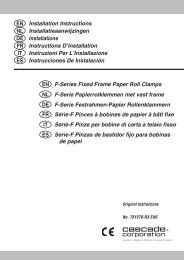
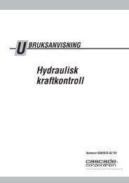
6.1-4 Torque Values<br />
Fastener torque values for the <strong>150H</strong> <strong>Fork</strong> <strong>Positioner</strong> are<br />
shown in the table below in both U.S. and Metric units. All<br />
torque values are also called out in each specific service<br />
procedure section throughout the Manual.<br />
Ref. Fastener Size Ft.-lbs. Nm<br />
1 Frame-to-carriage or sideshifter (4) .5625 in. 110 145<br />
2 Cylinder-to-frame (2) .750 in. 160 220<br />
3 Cylinder rod-end anchor (2) .750 in 160 220<br />
4 Valve-to-frame (2) M-8 16 22<br />
5 Manifold-to-frame (2) M-10 33 44<br />
6 SS Lower Hooks (4) M-16 40 50<br />
7 Cylinder Piston 55 75■<br />
8 Cylinder Retainer 55 75▲<br />
■ Use Loctite 242 (Blue)<br />
▲ Use Anti-Seize Compound<br />
7<br />
3Anchor Nut<br />
Piston Nut<br />
NOTE: Nut tightens against rod<br />
shoulder. Joint must function<br />
with an operating clearance.<br />
2<br />
8<br />
Retainer<br />
219473 Rev. 1 23<br />
4<br />
6<br />
Back (Driver’s) View<br />
(<strong>Fork</strong> <strong>Positioner</strong> shown mounted on Sideshifter)<br />
5<br />
1<br />
FP0212.ill<br />
FP0219.ill
Do you have questions you need answered right now?<br />
Call your nearest <strong>Cascade</strong> Service Department.<br />
Visit us online at www.cascorp.com<br />
AMERICAS<br />
<strong>Cascade</strong> <strong>Corporation</strong><br />
U.S. Headquarters<br />
2201 NE 201st<br />
Fairview, OR 97024-9718<br />
Tel: 800-CASCADE (227-2233)<br />
Fax: 888-329-8207<br />
EUROPE-AFRICA<br />
<strong>Cascade</strong> Italia S.R.L.<br />
European Headquarters<br />
Via Dell’Artigianato 1<br />
37050 Vago di Lavagno (VR)<br />
Italy<br />
Tel: 39-045-8989111<br />
Fax: 39-045-8989160<br />
ASIA-PACIFIC<br />
<strong>Cascade</strong> Japan Ltd.<br />
2-23, 2-Chome,<br />
Kukuchi Nishimachi<br />
Amagasaki, Hyogo<br />
Japan, 661-0978<br />
Tel: 81-6-6420-9771<br />
Fax: 81-6-6420-9777<br />
<strong>Cascade</strong> Australia Pty. Ltd.<br />
1445 Ipswich Road<br />
Rocklea, QLD 4107<br />
Australia<br />
Tel: 1-800-227-223<br />
Fax: +61 7 3373-7333<br />
c<br />
<strong>Cascade</strong> Canada Inc.<br />
5570 Timberlea Blvd.<br />
Mississauga, Ontario<br />
Canada L4W-4M6<br />
Tel: 905-629-7777<br />
Fax: 905-629-7785<br />
<strong>Cascade</strong> (Africa) Pty. Ltd.<br />
PO Box 625, Isando 1600<br />
60A Steel Road<br />
Sparton, Kempton Park<br />
South Africa<br />
Tel: 27-11-975-9240<br />
Fax: 27-11-394-1147<br />
<strong>Cascade</strong> Korea<br />
121B 9L Namdong Ind.<br />
Complex, 691-8 Gojan-Dong<br />
Namdong-Ku<br />
Inchon, Korea<br />
Tel: +82-32-821-2051<br />
Fax: +82-32-821-2055<br />
<strong>Cascade</strong> New Zealand<br />
15 Ra Ora Drive<br />
East Tamaki, Auckland<br />
New Zealand<br />
Tel: +64-9-273-9136<br />
Fax: +64-9-273-9137<br />
<strong>Cascade</strong> do Brasil<br />
Rua João Guerra, 134<br />
Macuco, Santos - SP<br />
Brasil 11015-130<br />
Tel: 55-13-2105-8800<br />
Fax: 55-13-2105-8899<br />
<strong>Cascade</strong>-Xiamen<br />
No. 668 Yangguang Rd.<br />
Xinyang Industrial Zone<br />
Haicang, Xiamen City<br />
Fujian Province<br />
P.R. China 361026<br />
Tel: 86-592-651-2500<br />
Fax: 86-592-651-2571<br />
Sunstream Industries<br />
Pte. Ltd.<br />
18 Tuas South Street 5<br />
Singapore 637796<br />
Tel: +65-6795-7555<br />
Fax: +65-6863-1368<br />
<strong>Cascade</strong> India Material<br />
Handling Private Limited<br />
No 34, Global Trade Centre<br />
1/1 Rambaugh Colony<br />
Lal Bahadur Shastri Road,<br />
Navi Peth, Pune 411 030<br />
(Maharashtra) India<br />
Phone: +91 020 2432 5490<br />
Fax: +91 020 2433 0881<br />
<strong>Cascade</strong> <strong>Corporation</strong> 2004 7-2004 Part Number 219473 R-1