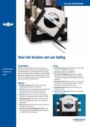
150H Fork Positioner - Cascade Corporation
150H Fork Positioner - Cascade Corporation
150H Fork Positioner - Cascade Corporation

Create successful ePaper yourself
Turn your PDF publications into a flip-book with our unique Google optimized e-Paper software.
T<br />
ROUBLESHOOTING<br />
4.1 General Procedures<br />
4.1-1 Truck System Requirements<br />
• Truck hydraulic pressure should be within the pressure<br />
range as shown in Section 6.1. PRESSURE MUST<br />
NOT EXCEED 2600 psi (180 bar).<br />
• Truck hydraulic flow should be within the volume range<br />
as shown in Section 6.1 .<br />
• Truck hydraulic fluid supplied to the Attachment must<br />
meet the specifications as shown in Section 6.1.<br />
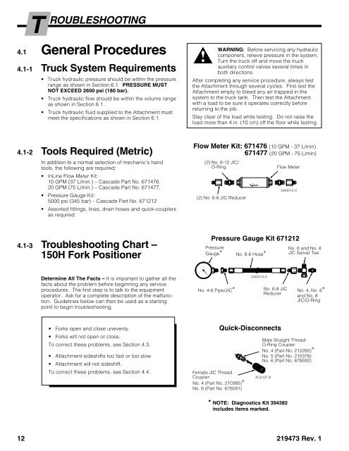
4.1-2 Tools Required (Metric)<br />
In addition to a normal selection of mechanic’s hand<br />
tools, the following are required:<br />
• InLine Flow Meter Kit:<br />
10 GPM (37 L/min.) – <strong>Cascade</strong> Part No. 671476.<br />
20 GPM (75 L/min.) – <strong>Cascade</strong> Part No. 671477.<br />
• Pressure Gauge Kit:<br />
5000 psi (345 bar) – <strong>Cascade</strong> Part No. 671212<br />
• Assorted fittings, lines, drain hoses and quick-couplers<br />
as required.<br />
4.1-3 Troubleshooting Chart –<br />
<strong>150H</strong> <strong>Fork</strong> <strong>Positioner</strong><br />
Determine All The Facts – It is important to gather all the<br />
facts about the problem before beginning any service<br />
procedures. The first step is to talk to the equipment<br />
operator. Ask for a complete description of the malfunction.<br />
Guidelines below can then be used as a starting<br />
point to begin troubleshooting.<br />
• <strong>Fork</strong>s open and close unevenly.<br />
• <strong>Fork</strong>s will not open or close.<br />
To correct these problems, see Section 4.3.<br />
• Attachment sideshifts too fast or too slow<br />
• Attachment will not sideshift.<br />
To correct these problems, see Section 4.4.<br />
WARNING: Before servicing any hydraulic<br />
component, relieve pressure in the system.<br />
Turn the truck off and move the truck<br />
auxiliary control valves several times in<br />
both directions.<br />
After completing any service procedure, always test<br />
the Attachment through several cycles. First test the<br />
Attachment empty to bleed any air trapped in the<br />
system to the truck tank. Then test the Attachment<br />
with a load to be sure it operates correctly before<br />
returning to the job.<br />
Stay clear of the load while testing. Do not raise the<br />
load more than 4 in. (10 cm) off the floor while testing.<br />
Flow Meter Kit: 671476 (10 GPM - 37 L/min)<br />
671477 (20 GPM - 75 L/min)<br />
(2) No. 8-12 JIC/<br />
O-Ring<br />
(2) No. 6-8 JIC Reducer<br />
Pressure Gauge Kit 671212<br />
Pressure<br />
Gauge*<br />
No. 4-6 Pipe/JIC*<br />
Female JIC Thread<br />
Coupler:<br />
No. 4 (Part No. 210385)*<br />
No. 6 (Part No. 678591)<br />
No. 6-6 Hose*<br />
GA0014.ill<br />
No. 6-8 JIC<br />
Reducer<br />
Quick-Disconnects<br />
AC0127.ill<br />
* NOTE: Diagnostics Kit 394382<br />
includes items marked.<br />
Flow Meter<br />
GA0013.ill<br />
No. 6 and No. 8<br />
JIC Swivel Tee<br />
No. 4, No. 6*<br />
and No. 8<br />
JIC/O-Ring<br />
Male Straight Thread<br />
O-Ring Coupler:<br />
No. 4 (Part No. 212282)*<br />
No. 5 (Part No. 210378)<br />
No. 6 (Part No. 678592)<br />
12 219473 Rev. 1