SPECIFICATIONS FOR LCD MODULE - OLED-LCD-TFT
SPECIFICATIONS FOR LCD MODULE - OLED-LCD-TFT
SPECIFICATIONS FOR LCD MODULE - OLED-LCD-TFT

Create successful ePaper yourself
Turn your PDF publications into a flip-book with our unique Google optimized e-Paper software.
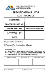
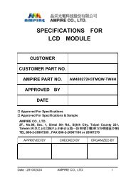
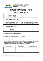
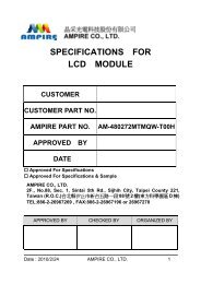
<strong>SPECIFICATIONS</strong> <strong>FOR</strong><br />
<strong>LCD</strong> <strong>MODULE</strong><br />
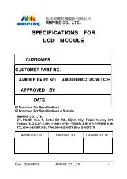
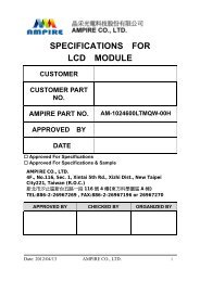
CUSTOMER<br />
CUSTOMER PART NO.<br />
AMPIRE PART NO. AM-800480WTMQW-00H<br />
APPROVED BY<br />
DATE<br />
� Approved For Specifications<br />
� Approved For Specifications & Sample<br />
AMPIRE CO., LTD.<br />
Building D., 2F., No.88, Sec. 1, Sintai 5th Rd., Sijhih City,<br />
Taipei County 221, Taiwan (R.O.C.)<br />
台北縣汐止市新台五路一段 88 號 2 樓(東方科學園區 D 棟)<br />
TEL:886-2-26967269 , FAX:886-2-86967196 or 26967270<br />
APPROVED BY CHECKED BY ORGANIZED BY<br />
Date : 2010/7/14 AMPIRE CO., LTD. 1
RECORD OF REVISION<br />
Revision Date Page Contents Editor<br />
2010/7/13<br />
-<br />
New Release<br />
Kevin<br />
Date : 2010/7/14 AMPIRE CO., LTD. 2
1. INTRODUCTION<br />
Ampire Display Module AM-800480W is a color active matrix <strong>TFT</strong>-<strong>LCD</strong> that uses<br />
amorphous silicon <strong>TFT</strong> as a switching device . This model is composed of a <strong>TFT</strong>-<strong>LCD</strong><br />
panel ,This <strong>TFT</strong>-<strong>LCD</strong> has a high resolution (800(R.G.B) X 480) and can display up to<br />
262,144 or 16.7M colors .<br />
2. PHYSICAL <strong>SPECIFICATIONS</strong><br />
Item Specifications unit<br />
Display resolution(dot) 800RGB (W) x 480(H) dots<br />
Active area 154.08 (W) x 85.92 (H) mm<br />
Pixel pitch 0.0642 (W) x 0.1790 (H) mm<br />
Color configuration R.G.B stripe<br />
Overall dimension 164.9 (W)x100.0(H)x5.7(D) mm<br />
Weight 150 g<br />
Brightness 400 nit(typ) cd/m 2<br />
Contrast ratio 500 : 1<br />
Backlight unit LED<br />
Display color 262K / 16.7M colors<br />
Date : 2010/7/14 AMPIRE CO., LTD. 3
3. Operation Specifications<br />
3-1 ABSOLUTE MAX. RATINGS<br />
Power voltage<br />
Item Symbol Min Max Unit<br />
DVdd -0.3 5.0 V<br />
AVdd 6.5 13.5 V<br />
VGH -0.3 40.0 V<br />
VGL -20.0 0.3 V<br />
VGH-VGL - 40.0 V<br />
Operation Temperature Top -30 85 ℃<br />
Storage Temperature Tst -30 85 ℃<br />
LED Reverse Voltage Vr - 1.2 V<br />
LED Forward Current If - 25 mA<br />
The following values are maximum operation conditions , If exceeded , it may cause<br />
faulty operation or damage<br />
3-2 Typical Opepration Conditions<br />
Power voltage<br />
Item Symbol Min Typ Max Unit<br />
DVdd 3.0 3.3 3.6 V<br />
AVdd 10.2 10.4 10.6 V<br />
VGH 15.3 16.0 16.7 V<br />
VGL -7.7 -7.0 -6.3 V<br />
Input signal voltage Vcom 3.6 3.8 4.0 V<br />
Input logic high voltage Vih 0.7 DVdd - DVdd V<br />
Input logic low voltage Vr 0 - 0.3 DVdd V<br />
Note 1: Be sure to apply DVdd and VGL to the <strong>LCD</strong> first, and then apply VGH<br />
Note 2: DVdd setting should match the signals output voltage of customer’s system<br />
Note 3: DCLK,HS,VS,RESET,U/D,L/R,DE,R0~R7,G0~G7,B0~B7,MODE,DITHB<br />
Date : 2010/7/14 AMPIRE CO., LTD. 4
3-3 Current Consumption<br />
Current for Driver<br />
Item Symbol Min Typ Max Unit Remark<br />
3-4 Backlight Driving Conditions<br />
Igh - 0.2 1.0 mA Vgh=16.0V<br />
Igl - 0.2 1.0 mA Vgl=-7.0V<br />
IDVdd - 4.0 10 mA DVdd=3.3V<br />
IAVdd - 20 50 mA AVdd=10.4V<br />
Item Symbol Min Typ Max Unit Remark<br />
Voltage for LED backlight VL 8.4 9.3 10.2 V Note 1<br />
Current for LED backlight Igl 170 180 200 mA<br />
LED life time - 20,000 - - Hr Note 2<br />
Note1: The LED Supply Voltage is defined by the number of LED at Ta=25℃ and<br />
IL=180mA.<br />
Note2: The”LED life time“ id defined as the module brightness decrease to 50% original<br />
brightness at Ta=25℃ and IL=180mA. The LED lifetime could be decreased if<br />
operating IL is larger than 180mA.<br />
Date : 2010/7/14 AMPIRE CO., LTD. 5
4. Power Sequence<br />
Date : 2010/7/14 AMPIRE CO., LTD. 6
5. Timing Characteristics<br />
5-1 AC Electrical Characteristics<br />
Item Symbol Min Typ Max Unit Remark<br />
HS setup time Thst 8 - - ns<br />
HS hold time Thhd 8 - - ns<br />
VS setup time Tvst 8 - - ns<br />
VS hold time Tvhd 8 - - ns<br />
Data setup time Tdsu 8 - - ns<br />
Data hold time Tdud 8 - - ns<br />
DE setup time Tesu 8 - - ns<br />
DE hold time Tehd 8 - - ns<br />
DVdd Power On Slew rate TPOR - - 20 ms<br />
RESET pulse width Trst 1 - - ms<br />
DCLK cycle time Tcoh 20 - - ns<br />
DCLK pulse duty Tcwh 40 50 60 %<br />
5-2 Timing<br />
From 0 to 90%<br />
DVdd<br />
Item Symbol Min Typ Max Unit Remark<br />
Horizontal Display Area thd - 800 - DCLK<br />
DCLK Frequency fclk 26.4 33.3 46.8 MHz<br />
One Horizontal Line th 862 1056 1200 DCLK<br />
HS pulse width thpw 1 - 40 DCLK<br />
HS Blanking thb 46 46 46 DCLK<br />
HS Front Porch thfp 16 210 354 DCLK<br />
Date : 2010/7/14 AMPIRE CO., LTD. 7
Item Symbol Min Typ Max Unit Remark<br />
Vertical Display Area tvd - 480 - TH<br />
VS period time tv 510 525 650 TH<br />
VS pulse width tvpw 1 - 20 TH<br />
VS Blanking tvb 23 23 23 TH<br />
VS Front Porch tvfp 7 22 147 TH<br />
5-3 Data Input Format<br />
Date : 2010/7/14 AMPIRE CO., LTD. 8
6. Pin Assignment<br />
Pin No Symbol I/O Function Remark<br />
1 VLED+ P Power for LED backlight (Anode)<br />
2 VLED+ P Power for LED backlight (Anode)<br />
3 VLED- P Power for LED backlight (Cathode)<br />
4 VLED- P Power for LED backlight (Cathode)<br />
5 GND P Power Ground<br />
6 VCOM I Common voltage<br />
7 DVdd P Power for Digital Circuit<br />
8 MODE I DE/SYNC mode select Note1<br />
9 DE I Data Input Enable<br />
10 VS I Vertical Sync Input<br />
11 HS I Horizontal Sync Input<br />
12 B7 I Blue data (MSB)<br />
13 B6 I Blue data<br />
14 B5 I Blue data<br />
15 B4 I Blue data<br />
16 B3 I Blue data<br />
17 B2 I Blue data<br />
18 B1 I Blue data Note 2<br />
19 B0 I Blue data (LSB) Note 2<br />
20 G7 I Green data (MSB)<br />
21 G6 I Green data<br />
22 G5 I Green data<br />
Date : 2010/7/14 AMPIRE CO., LTD. 9
23 G4 I Green data<br />
24 G3 I Green data<br />
25 G2 I Green data<br />
26 G1 I Green data Note 2<br />
27 G0 I Green data (LSB) Note 2<br />
28 R7 I Red data<br />
29 R6 I Red data<br />
30 R5 I Red data<br />
31 R4 I Red data<br />
32 R3 I Red data<br />
33 R2 I Red data<br />
34 R1 I Red data Note 2<br />
35 R0 I Red data (LSB) Note 2<br />
36 GND P Power Ground<br />
37 DCLK I Sample clock Note 3<br />
38 GND P Power Ground<br />
39 L/R I Left / Right selection Note 4,5<br />
40 U/D I Up / Down selection Note 4,5<br />
41 VGH P Gate ON Voltage<br />
42 VGL P Fate OFF Voltage<br />
43 AVdd P Power for Analog Circuit<br />
44 RESET I Global reset pin Note 6<br />
45 NC - No Connection<br />
46 VCOM I Common Vlotage<br />
47 DITHB I Dithering Function Note7<br />
48 GND P Power Ground<br />
Date : 2010/7/14 AMPIRE CO., LTD. 10
49 NC - No Connection<br />
50 NC - No Connection<br />
Note 1: DE/SYNC mode select. Normally pull high.<br />
When select DE mode, MODE=”1”, VS and HS must pull high.<br />
When select SYNC mode, MODE=”0”, DE must be grounded.<br />
Note 2: When input 18 bits RGB data, the two low bits of RGB data must be grounded.<br />
Note 3: Data shall be latched at the falling edge of DCLK.<br />
Note 4: Selection of scanning mode<br />
Note 5: Definition of scanning direction. Refer to the figure below:<br />
Date : 2010/7/14 AMPIRE CO., LTD. 11
Note 6: Global reset pin. Active low to enter reset state. Suggest to connect with an RC<br />
reset circuit for stability. Normally pull high.<br />
Note 7: Dithering function enable control, normally pull high.<br />
When DITHB=”1”, Disable internal dithering function.<br />
When DITHB=”0”, Enable internal dithering function.<br />
7. OPTICAL CHARACTERISTICS<br />
Date : 2010/7/14 AMPIRE CO., LTD. 12
Date : 2010/7/14 AMPIRE CO., LTD. 13
Note3: Definition of Response time<br />
Date : 2010/7/14 AMPIRE CO., LTD. 14
Bmax: The measured maximum luminance of all measurement position<br />
Bmin: The measured minimum luminance of all measurement position<br />
Date : 2010/7/14 AMPIRE CO., LTD. 15
8. Reliability Test Items<br />
Date : 2010/7/14 AMPIRE CO., LTD. 16
9. Outline Dimension<br />
Date : 2010/7/14 AMPIRE CO., LTD. 17
Date : 2010/7/14 AMPIRE CO., LTD. 18