Prisma II Chassis 56-Port Upgrade Technical Bulletin - DNIP . NET
Prisma II Chassis 56-Port Upgrade Technical Bulletin - DNIP . NET
Prisma II Chassis 56-Port Upgrade Technical Bulletin - DNIP . NET
You also want an ePaper? Increase the reach of your titles
YUMPU automatically turns print PDFs into web optimized ePapers that Google loves.
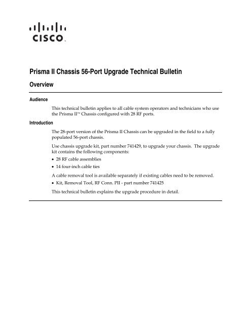
<strong>Prisma</strong> <strong>II</strong> <strong>Chassis</strong> <strong>56</strong>-<strong>Port</strong> <strong>Upgrade</strong> <strong>Technical</strong> <strong>Bulletin</strong><br />
Overview<br />
Audience<br />
Introduction<br />
This technical bulletin applies to all cable system operators and technicians who use<br />
the <strong>Prisma</strong> <strong>II</strong> <strong>Chassis</strong> configured with 28 RF ports.<br />
The 28-port version of the <strong>Prisma</strong> <strong>II</strong> <strong>Chassis</strong> can be upgraded in the field to a fully<br />
populated <strong>56</strong>-port chassis.<br />
Use chassis upgrade kit, part number 741429, to upgrade your chassis. The upgrade<br />
kit contains the following components:<br />
• 28 RF cable assemblies<br />
• 14 four-inch cable ties<br />
A cable removal tool is available separately if existing cables need to be removed.<br />
• Kit, Removal Tool, RF Conn. P<strong>II</strong> - part number 741425<br />
This technical bulletin explains the upgrade procedure in detail.
<strong>Chassis</strong> <strong>Upgrade</strong> Procedure<br />
Upgrading the <strong>Chassis</strong> to <strong>56</strong>-<strong>Port</strong>s<br />
Follow these steps to upgrade your <strong>Prisma</strong> <strong>II</strong> <strong>Chassis</strong> from 28 to <strong>56</strong> RF ports.<br />
1. Remove power to the chassis by unplugging all power cables from the back of<br />
the chassis.<br />
2. Loosen the 10 captive screws that secure the RF connector back panel to the<br />
chassis and carefully tilt the panel down to expose the existing 28 RF cables.<br />
Result: The back panel is removed and you have access to the backplane<br />
inside the chassis.<br />
Continued on next page<br />
2 <strong>Prisma</strong> <strong>II</strong> <strong>Chassis</strong> <strong>56</strong>-<strong>Port</strong> <strong>Upgrade</strong> <strong>Technical</strong> <strong>Bulletin</strong> 4010254 Rev C
<strong>Chassis</strong> <strong>Upgrade</strong> Procedure, Continued<br />
3. Install an RF cable connector into port C of one slot on the backplane.<br />
Push the connector in by hand until you feel and hear it snap into place. (The<br />
connector is held in place by an integral spring ferrule on the connector.)<br />
Note: When properly seated, you should not be able to pull the connector out<br />
of the backplane with your fingers. If you need to remove a connector, use<br />
the removal tool, part number 741425. From the front side of the backplane,<br />
carefully insert the tool over the ferrule until it is fully seated. A slight<br />
rotating motion makes insertion easier. Then gently push the connector back<br />
out of the backpane.<br />
Important: Dress all cables at about a 45° angle to the right and down from<br />
the connector so they lay neatly next to the existing RF cables for the slot.<br />
Continued on next page<br />
4010254 Rev C <strong>Prisma</strong> <strong>II</strong> <strong>Chassis</strong> <strong>56</strong>-<strong>Port</strong> <strong>Upgrade</strong> <strong>Technical</strong> <strong>Bulletin</strong> 3
<strong>Chassis</strong> <strong>Upgrade</strong> Procedure, Continued<br />
4. Repeat step 3 for port D of the same slot.<br />
5. Check that the RF connectors for the slot are properly seated in the backplane<br />
by installing a module with four RF ports into the slot. The module should<br />
seat properly in the slot without excessive force.<br />
Note: Remove the module after testing the fit.<br />
6. Remove the black plastic plugs for the F-connectors in the back panel for port<br />
C of the slot that you are working on.<br />
Note: Use a pair of pliers to compress the retaining ears on the plastic plug<br />
from the inside of the back panel and push the plug out.<br />
7. Install the F-connector of the RF cable connected to port C on the backplane<br />
into the mounting hole for port C of the same slot on the back panel.<br />
See the sample mounting arrangement in the illustration below.<br />
While holding the body of the F-connector from behind the back panel,<br />
tighten the retaining nut to 50 lb-in (5.65 Nm).<br />
Important: Note that the ports are labeled A to D from the bottom up on the<br />
back panel and labeled A to D from the top down on the backplane inside the<br />
chassis. Make sure you connect both ends of one RF cable to the same port.<br />
<strong>Port</strong> C to port C, etc.<br />
8. Repeat step 7 for port D of the same slot.<br />
Continued on next page<br />
4 <strong>Prisma</strong> <strong>II</strong> <strong>Chassis</strong> <strong>56</strong>-<strong>Port</strong> <strong>Upgrade</strong> <strong>Technical</strong> <strong>Bulletin</strong> 4010254 Rev C
<strong>Chassis</strong> <strong>Upgrade</strong> Procedure, Continued<br />
9. Use a new cable tie to secure the two new RF cables for the slot to the existing<br />
RF cables for the slot.<br />
Notes:<br />
• Be sure to dress the cables so they lay neatly next to the existing RF cables<br />
for the slot.<br />
• Do NOT cut off the existing cable tie. Instead wrap all four cables in the<br />
new cable tie, leaving the existing cable tie in place to hold the cables to the<br />
bottom of the chassis.<br />
• Do NOT over tighten the cable tie or you may damage the cables.<br />
10. Repeat steps 3 through 9 for each slot in the chassis.<br />
Result: The chassis is fully populated with <strong>56</strong> RF ports.<br />
11. Slowly tilt the chassis back panel, with all RF cables installed, up into position<br />
over its chassis mounting position and lined up with its captive mounting<br />
screw holes.<br />
Note: Be sure to pre-form the RF cables as the back panel is moved into<br />
position to ensure that the cables are not pinched or subject to a severe bend<br />
radius.<br />
Continued on next page<br />
4010254 Rev C <strong>Prisma</strong> <strong>II</strong> <strong>Chassis</strong> <strong>56</strong>-<strong>Port</strong> <strong>Upgrade</strong> <strong>Technical</strong> <strong>Bulletin</strong> 5
<strong>Chassis</strong> <strong>Upgrade</strong> Procedure, Continued<br />
12. Tighten the 10 captive screws that secure the RF connector back panel to the<br />
chassis.<br />
Result: The <strong>Prisma</strong> <strong>II</strong> <strong>Chassis</strong> has been upgraded to a <strong>56</strong>-port chassis.<br />
6 <strong>Prisma</strong> <strong>II</strong> <strong>Chassis</strong> <strong>56</strong>-<strong>Port</strong> <strong>Upgrade</strong> <strong>Technical</strong> <strong>Bulletin</strong> 4010254 Rev C
For Information<br />
If You Have Questions<br />
If you have technical questions, call Cisco Services for assistance. Follow the menu options to speak with<br />
a service engineer.<br />
4010254 Rev C <strong>Prisma</strong> <strong>II</strong> <strong>Chassis</strong> <strong>56</strong>-<strong>Port</strong> <strong>Upgrade</strong> <strong>Technical</strong> <strong>Bulletin</strong> 7
Cisco Systems, Inc.<br />
5030 Sugarloaf Parkway, Box 465447<br />
Lawrenceville, GA 30042<br />
678 277-1120<br />
800 722-2009<br />
www.cisco.com<br />
Cisco and the Cisco logo are trademarks or registered trademarks of Cisco and/or its affiliates<br />
in the U.S. and other countries. To view a list of Cisco trademarks, go to this URL:<br />
www.cisco.com/go/trademarks .<br />
Third party trademarks mentioned are the property of their respective owners.<br />
The use of the word partner does not imply a partnership relationship between Cisco and any<br />
other company. (1110R)<br />
Product and service availability are subject to change without notice.<br />
© 2005, 2008, 2012 Cisco and/or its affiliates. All rights reserved.<br />
November 2012 Printed in USA Part Number 4010254 Rev C


