Gas Purge Bubbler H-3551 - WaterLOG
Gas Purge Bubbler H-3551 - WaterLOG
Gas Purge Bubbler H-3551 - WaterLOG

You also want an ePaper? Increase the reach of your titles
YUMPU automatically turns print PDFs into web optimized ePapers that Google loves.
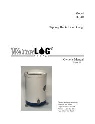
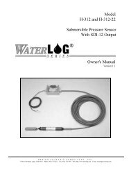
Model<br />
H-<strong>3551</strong><br />
<strong>Gas</strong> <strong>Purge</strong> <strong>Bubbler</strong><br />
Owner's Manual<br />
Version 3.0<br />
D E S I G N A N A L Y S I S A S S O C I A T E S , I N C .<br />
75 West 100 South, Logan, Utah 84321 Phone: (435) 753-2212 Fax: (435) 753-7669 Web: http://www.waterlog.com E-mail: waterlog@waterlog.com
D E S I G N A N A L Y S I S A S S O C I A T E S , I N C .<br />
75 West 100 South, Logan, Utah 84321 Phone: (435) 753-2212 Fax: (435) 753-7669 Web: http://www.waterlog.com E-mail: waterlog@waterlog.com
User Agreement/<br />
WATERLOG ® Warranty<br />
1. NATURE OF THE PRODUCT<br />
This agreement accompanies an interface module comprising firmware, circuitry and other electronic<br />
equipment in an enclosed housing, and packaged together with written instructional materials. The<br />
packaged electronic circuitry and instructional materials herein are collectively referred to as the<br />
“PRODUCT.” The PRODUCT is made available from DESIGN ANALYSIS ASSOCIATES, INC., of<br />
75 West 100 South, Logan, Utah 84321 (hereinafter referred to as “DESIGN ANALYSIS”), and contains<br />
information and embodies technology that is confidential and proprietary to DESIGN ANALYSIS, and the<br />
availability and use of the PRODUCT is extended to you, the USER, solely on the basis of the terms of<br />
agreement which follow.<br />
2. ACKNOWLEDGMENTS BY USER<br />
Opening the package which encloses the accompanying PRODUCT indicates your acceptance of the terms<br />
and conditions of this agreement and constitutes an acknowledgment by you of the confidential and<br />
proprietary nature of the rights of DESIGN ANALYSIS in the PRODUCT.<br />
3. DUTIES OF YOU, THE USER<br />
In consideration for the access to and use of the PRODUCT extended to you by DESIGN ANALYSIS and<br />
to protect the confidential and proprietary information of DESIGN ANALYSIS, USER agrees as follows:<br />
(a) USER agrees that they will not remove from the exterior of the housing of the PRODUCT any safety<br />
warnings or notices of proprietary interest placed thereon by DESIGN ANALYSIS.<br />
(b) USER agrees that they shall not disassemble or otherwise reverse engineer the PRODUCT.<br />
(c) USER agrees to treat the PRODUCT with the same degree of care as USER exercises in relation to<br />
their own confidential and proprietary information.<br />
4. TERM<br />
USER may enjoy these rights only as long as their possession of the PRODUCT shall continue to be<br />
rightful. These rights will cease if the PRODUCT is returned to DESIGN ANALYSIS under the terms of<br />
any redemption offer, warranty, or money-back guarantee, or if USER transfers the PRODUCT to another<br />
party on terms inconsistent with this agreement.<br />
5. LIMITED WARRANTY<br />
(b) What is Covered<br />
DESIGN ANALYSIS warrants that for a period of twelve months from the time of purchase the<br />
functions to be performed by the PRODUCT will be substantially in compliance with USER<br />
documentation. DESIGN ANALYSIS also warrants that the PRODUCT will be free from defects<br />
in materials and workmanship for a period of ONE YEAR from the date of purchase.<br />
(b) What USER Must Do<br />
If the product fails to satisfy the above warranty, USER must notify DESIGN ANALYSIS in<br />
writing within the applicable period specified above and reasonably cooperate with the directions<br />
they received from DESIGN ANALYSIS.<br />
H-<strong>3551</strong> User Agreement/WATERLOG ® Warranty W-1
(c) What DESIGN ANALYSIS Will Do<br />
DESIGN ANALYSIS will repair the PRODUCT or will endeavor to provide a replacement of<br />
same within a reasonable period of time. In the event that DESIGN ANALYSIS is unable to make<br />
the necessary repairs or replacement within a reasonable period of time, the original purchase price<br />
will be refunded upon the return of the PRODUCT to DESIGN ANALYSIS.<br />
(d) Limitations<br />
(i) THE ENTIRE REMEDY FOR BREACH OF THIS LIMITED WARRANTY SHALL<br />
BE LIMITED TO REPLACEMENT OF THE DEFECTIVE PRODUCT OR<br />
REFUNDING OF THE PURCHASE PRICE, AS SET FORTH ABOVE. IN NO<br />
EVENT WILL THE LIABILITY OF DESIGN ANALYSIS TO USER OR TO ANY<br />
OTHER PARTY EXCEED THE ORIGINAL PURCHASE PRICE OF THE PRODUCT,<br />
REGARDLESS OF THE FORM OF THE CLAIM.<br />
(ii) EXCEPT FOR THE EXPRESS WARRANTIES ABOVE, DESIGN ANALYSIS<br />
SPECIFICALLY DISCLAIMS ALL OTHER WARRANTIES, INCLUDING,<br />
WITHOUT LIMITATION, ALL IMPLIED WARRANTIES OF MERCHANTABILITY<br />
AND FITNESS FOR A PARTICULAR PURPOSE.<br />
(iii) UNDER NO CIRCUMSTANCES WILL DESIGN ANALYSIS BE LIABLE FOR<br />
SPECIAL, INCIDENTAL, CONSEQUENTIAL, INDIRECT, OR ANY OTHER<br />
DAMAGES OR CLAIMS ARISING FROM THE USE OF THIS PRODUCT, THIS<br />
INCLUDES LOSS OF PROFITS OR ANY OTHER COMMERCIAL DAMAGES,<br />
EVEN IF ADVISED OF THE POSSIBILITY OF SUCH DAMAGES. IN NO EVENT<br />
WILL DESIGN ANALYSIS BE LIABLE FOR ANY CLAIMS, LIABILITY, OR<br />
DAMAGES ARISING FROM MODIFICATION MADE THEREIN, OTHER THAN<br />
BY DESIGN ANALYSIS.<br />
(iv) THIS LIMITED WARRANTY GIVES USER SPECIFIC LEGAL RIGHTS. USER<br />
MAY ALSO HAVE OTHER RIGHTS WHICH VARY FROM STATE TO STATE.<br />
SOME STATES DO NOT ALLOW LIMITATIONS ON HOW LONG AN IMPLIED<br />
WARRANTY LASTS OR THE EXCLUSION OF INCIDENTAL OR<br />
CONSEQUENTIAL DAMAGES, SO THOSE LIMITATIONS OR EXCLUSIONS<br />
MAY NOT APPLY.<br />
6. GOVERNING LAW<br />
This Agreement and its validity and interpretation shall be governed by the laws of the State of Utah,<br />
notwithstanding any choice of law rules of Utah or any other state or jurisdiction.<br />
W-2 User Agreement/WATERLOG ® Warranty H-<strong>3551</strong>
Chapter 1<br />
Introduction<br />
1.0 Introduction<br />
The WATERLOG ® Model H-<strong>3551</strong> is a self-contained "smart" gas purge system which produces a<br />
precision, constant mass flow of gas. Together with a pressure measurement device, it is used to measure<br />
fluid levels in applications such as surface water (streams and lakes, etc.), ground water and tanks.<br />
The H-<strong>3551</strong> uses a battery operated compressor to maintain pressure in an internal tank. An internal<br />
microprocessor controller determines how much pressure is needed in the tank, based on the current head<br />
pressure, to produce a constant bubble rate. Hence, the term "smart". The compressor and tank replace the<br />
dry nitrogen tank used in previous systems.<br />
The H-<strong>3551</strong> uses a sophisticated system of sensors and valves to regulate the bubble rate and purge<br />
pressure. This portion of the H-<strong>3551</strong> replaces the sight feed flow controller and pressure regulator<br />
(Conoflow system) used in previous systems.<br />
The H-<strong>3551</strong> is used primarily with the WATERLOG ® Series Model H-350XL which performs several<br />
different functions in the system: First, it is the precision pressure measurement source for measuring the<br />
fluid level. This function replaces the manometer in previous systems. Second, it is the terminal through<br />
which the H-<strong>3551</strong> is configured. Third, it can be the data recorder for the system, thus removing the need<br />
for an external data recorder.<br />
The H-<strong>3551</strong>'s provides a purge feature which temporarily pumps up the tank to a high pressure and opens a<br />
valve to apply high pressure to the orifice line. This feature is designed to remove any sediment that may<br />
have collected in or around the outlet of the orifice line.<br />
1.1 Key Features<br />
Following is a list of some of the H-<strong>3551</strong>'s features:<br />
! Provides a continuous gas flow<br />
! Battery operated<br />
! Microprocessor controlled<br />
! One-piece manifold eliminates many potential sources of leaks<br />
! Pressure gauge provides a visual indication of the tank pressure<br />
! Hydrophobic intake membrane, protects compressor<br />
! All components are easily accessible for inspection and maintenance<br />
! Compressor does not have a “diaphragm”<br />
! Provides an internal pressure relief valve<br />
! Compressor is serviced and rated for cold temperature operation<br />
! Can be optionally controlled and monitored as an SDI-12 “sensor”<br />
H-<strong>3551</strong> Introduction 1-1
1.2 How it Works<br />
The H-<strong>3551</strong> has a motor driven compressor which maintains pressure in a small tank. <strong>Gas</strong> flows from the<br />
tank through a precision restriction to the output port. The pressure across the restriction is measured with<br />
a pressure transducer. By turning the compressor on and off, the micro controller attempts to maintain a<br />
constant pressure across the restriction. Thus maintaining a constant gas flow. The micro controller also<br />
compensates for the effects of gas density change with temperature to maintain a constant flow through the<br />
restriction.<br />
1.3 Unpacking the H-<strong>3551</strong><br />
You should have received the following items:<br />
1. WATERLOG ® Series H-<strong>3551</strong> "Smart <strong>Gas</strong>" system<br />
2. RS-485 Communications/power Cable<br />
3. Installation Kit<br />
4. This Owner’s Manual<br />
Please verify you have received these components and any other optional equipment you may have ordered.<br />
It is recommended that you visually inspect inside the H-<strong>3551</strong> enclosure to verify all electrical connections<br />
are secure, where some movement may have occurred during shipment.<br />
1.4 Testing the System<br />
Before installing the H-<strong>3551</strong>, you may wish to test the system in the shop or lab. This will familiarize you<br />
with the instrument in an environment where it is easy to work and you are near a telephone if questions<br />
should arise.<br />
If you are unable to get the H-<strong>3551</strong> up and running, refer to Chapter 2 (Installation) and Chapter 4<br />
(Trouble Shooting). If you have further questions, feel free to call one of our support personnel at (435)<br />
753-2212 for assistance.<br />
1-2 Introduction H-<strong>3551</strong>
2.1 Installing the WATERLOG ® Series Model H-<strong>3551</strong><br />
For proper installation of the H-<strong>3551</strong>, you will need:<br />
! The H-<strong>3551</strong><br />
! This Owner's Manual<br />
! RS-485 serial cable (provided)<br />
! Installation kit (provided)<br />
Chapter 2<br />
Installation<br />
Installation instructions for the H-<strong>3551</strong> may vary somewhat according to your specific application and field<br />
conditions.<br />
The photo below shows the input/output panel of the H-<strong>3551</strong> where you make connections for power,<br />
ground, communications, outlet to orifice, and pressure to your sensor. Observe the labels to determine<br />
where you should make your connections.<br />
H-<strong>3551</strong> Installation 2-1
2.2 Orifice and Sensor Connections<br />
In its simplest form, a gas purge pressure measurement system consists of a gas source, a pressure<br />
measurement device and an orifice tube all connected together in a “T” arrangement. Because the H-<strong>3551</strong><br />
has the capability of purging the orifice line, a more complex connection is required. Do not use a simple<br />
“T” connection to connect the bubbler and pressure sensor to the orifice line, instead, use the two<br />
dedicated ports of the H-<strong>3551</strong>. The H-<strong>3551</strong> includes an internal valve which isolates the pressure sensor<br />
output from the orifice line during a purge sequence. This helps prevent a plugged orifice condition from<br />
damaging the pressure sensor.<br />
If you are using a pressure sensor other than the H-350XL you may need to take extra precautions to<br />
further protect your pressure sensor. See Chapter3.<br />
2.3 Recommended Field Installation Procedures<br />
1. The H-355 must be wall mounted in the vertical position, with the manifold down. Mounting feet are<br />
provided. A vertical mount helps ensure moisture will not accumulate in the internal pressure tank.<br />
2. Connect the pressure line between the H-<strong>3551</strong> and your pressure measurement device. This can be<br />
done using the H-<strong>3551</strong>-Install kit. This kit is designed for use with the H-350XL. If your measurement<br />
device has different connections, you will need to provide the appropriate fittings. You will need a 1/8"<br />
NPT male tubing fitting for the sensor output. It is recommended that you use the 1/8" copper tubing<br />
supplied in the install kit. The proper ferrules must be used to insure there are no leaks.<br />
3. The H-<strong>3551</strong> requires two separate power sources. First is the compressor 12V which powers the<br />
compressor and control valves. This supply is typically made with heavy gauge wire to the gauge<br />
station 12V battery. Second is the 12V which powers the control module. This source is supplied from<br />
the pressure measurement sensor through the interface cable (provided), and into the control connector.<br />
It is best to connect the compressor power first, then the control power second. If a pumping sequence<br />
fails, the controller suspends pumping for a while to allow the battery to recharge. By connecting the<br />
pump power first, the controller will not prematurely detect a dead battery and suspend pumping.<br />
4. Generally, an external desiccator is required to dry the intake air. The desiccator prevents<br />
accumulation of moisture in the tank, restriction and orifice line. Connect the output of the desiccator<br />
to the port marked “intake”. Desiccators which employ “indicating” silica gel have the advantage of<br />
visually showing the status of the desiccant. As the gel becomes saturated with moisture the gel turns<br />
blue. See Appendix-B for further information and the specification for a recommended desiccator.<br />
2-2 Installation H-<strong>3551</strong>
2.4 Control Connector<br />
Pin No. Description Wire Color<br />
1 RS485DAT+ Black<br />
2 RS-485DAT- Brown<br />
3 GND Red<br />
4 GND Orange<br />
5 +12V Yellow<br />
6 +12V Green<br />
7 +12V<br />
8 SD-12 Data<br />
9 Gnd<br />
2.5 Connecting a WATERLOG ® Series Model H-350XL Pressure Sensor<br />
H-355<br />
60 Bubbles<br />
Per Minute<br />
RS-485<br />
H-350<br />
Pressure Line to H-350<br />
<strong>Gas</strong> <strong>Purge</strong> Line Orifice<br />
SDI-12 or RS-232<br />
Data Collection Platform/<br />
Data Logger<br />
Figure 2-2. H-355/350 Pressure Measurement System<br />
Control Connector &<br />
Pump Power Terminals<br />
Figure 2-2 shows a typical installation of a complete pressure measurement system.<br />
H-<strong>3551</strong> Installation 2-3
Please note the following:<br />
H-350XL pressure sensor and H-<strong>3551</strong> bubbler<br />
mounted on a plywood panel<br />
1. The install kit provided connects the “Sensor” output port of the bubbler directly to the<br />
“Pressure Input” of the H-350XL without any additional parts.<br />
2. The RS-485 serial cable provided is equipped with plugs on both ends for direct connection<br />
between the “control” input of the H-<strong>3551</strong> and the “Auxiliary output” of the H-350XL.<br />
2-4 Installation H-<strong>3551</strong>
Chapter 3<br />
Operation<br />
3.1 Pumping Operation<br />
During normal operation, if the tank pressure becomes too low the micro controller makes several<br />
tests before turning the compressor on:<br />
1. If the compressor power input (terminal strip) is below 10.0 volts, the compressor will not turn<br />
on. This is to prevent further discharge of an already stressed battery.<br />
2. The compressor will not turned on if a purge sequence within the previous elapsed 1-hour<br />
failed. This allows the battery charger to charge the battery without the compressor draining<br />
the battery as fast as it is charged.<br />
Once the compressor is turned on, the battery voltage is no longer monitored by the micro<br />
controller.<br />
3.1.1 Maintenance Pressure Pump Failure<br />
If the compressor runs longer than 60 seconds while pumping the tank to the pressure needed for<br />
the desired bubble rate, the micro controller turns off the compressor and disables further pumping<br />
for 30-seconds.<br />
3.1.2 <strong>Purge</strong> Pump Failure<br />
When a purge sequence is initiated, the compressor is activated to pump the tank to the specified<br />
purge pressure. If the compressor runs longer than 300 seconds while pumping the tank to the<br />
proper pressure, the micro controller turns off the compressor and disables all further pumping for<br />
1-hour.<br />
While servicing the system, these battery protection features can be inadvertently activated if the<br />
12V pump power (via the terminal strip) is disconnected or fails while the compressor is running.<br />
You can recover from these lockout conditions by momentarily disconnecting the RS-485 control<br />
connector to reset the micro controller.<br />
H-<strong>3551</strong> Operation 3-1
3.2 Operation with the H-350XL Pressure Sensor Attached<br />
The following is a description of the H-350XL submenus used for configuring the bubbler.<br />
Auto <strong>Purge</strong> Enbl[OFF]<br />
Bubble Rate[XXX]/min<br />
<strong>Purge</strong> Thresh[XXX]PSI<br />
<strong>Purge</strong> Presur[XXX]PSI<br />
<strong>Purge</strong> Time: [XXX]sec<br />
Manual <strong>Purge</strong>: ENT=Y<br />
Timed Prg: [XX] days<br />
Tank PSI = XX.X<br />
Diff PSI = XX.XX<br />
Last Prg=MM/DD HH:MM<br />
The H-350XL can sense when the orifice line is restricted or plugged. The system can be<br />
configured to do an automatic purge of the orifice line when it becomes necessary. This menu item<br />
turns the auto purge on or off.<br />
Auto <strong>Purge</strong> Enbl[OFF]<br />
This setting specifies the bubble rate that should flow from the end of the orifice tube. The<br />
programmable range is 30 to 120 bubbles per minute.<br />
Bubble Rate[XXX]/min<br />
This setting sets the purge threshold. If the orifice line pressure reaches the purge threshold, the<br />
H-350XL can initiate an auto purge. The range of “<strong>Purge</strong> Thresh” is 10 to 65 psi.<br />
<strong>Purge</strong> Thresh[XXX]PSI<br />
This setting is the pressure that the H-<strong>3551</strong> uses to purge the orifice line. The range is 15 to 80 psi.<br />
Set this value to a pressure which would reasonably purge sediment and debris from the orifice.<br />
Keep in mind that the higher pressures require more energy from the battery.<br />
<strong>Purge</strong> Presur[XXX]PSI<br />
3-2 Operation H-<strong>3551</strong>
This setting is the duration of a purge in seconds. The range is 30 to 240 seconds. Allow enough<br />
time for the purge to dissipate and the bubble rate to fall near zero.<br />
<strong>Purge</strong> Time: [XXX]sec<br />
Pressing on this item will initiate a purge sequence using the current purge settings.<br />
Manual <strong>Purge</strong>: ENT=Y<br />
This option is used to force a purge every XX days. The limits are 00 to 99 days. If the option is set<br />
to 00 then this option is in affect disabled. A value of 01 will cause a purge every day. The purge<br />
will happen after the first scan past noon.<br />
Timed Prg: [XX] days<br />
This value is the current pressure of the H-<strong>3551</strong>'s internal air tank in psi. This value is informative<br />
only and cannot be edited. The tank pressure should be approximately 3-5 PSI greater than the<br />
orifice pressure.<br />
Tank PSI = XX.X<br />
This value is the difference between the tank pressure and the pressure on the orifice line in psi.<br />
Like tank psi, this value cannot be edited. This value is directly proportional to the bubble rate and<br />
should be approximately 3-5 PSI.<br />
Diff PSI = XX.XX<br />
This display shows the month, day any hour when the last purge sequence was made.<br />
Last Prg=MM/DD HH:MM<br />
H-<strong>3551</strong> Operation 3-3
If the auto-purge feature of the H-350XL is enabled, the H-350XL is responsible for initiating<br />
purges. Whenever the H-350XL makes a measurement, it compares the pressure data with the<br />
“<strong>Purge</strong> Threshold” value. If the pressure is greater than the <strong>Purge</strong> Threshold, the H-350XL<br />
commands the bubbler to initiate a purge sequence. During the purge, the H-350XL energizes its<br />
internal auto-zero valve to isolate the H-350XL's precision sensor from the purge pressure. At the<br />
completion of the purge, the H-350XL keeps its auto-zero valve energized for an additional 2.0<br />
seconds. This is done to prevent damage to the H-350XL's precision sensor in case the orifice is<br />
plugged and the orifice line momentarily holds the full purge pressure. A pressure relief valve in<br />
the bubbler vents the over pressure to atmosphere during the 2 second delay.<br />
After completion of a purge sequence, the H-350XL makes another pressure measurement. If the<br />
pressure is still greater than the <strong>Purge</strong> Threshold value, the H-350XL knows the purge failed. It<br />
then activates a timer which disables further purges for the next 24 hours. This is done to prevent a<br />
plugged orifice form causing continuous purges which would quickly drain the battery.<br />
3.3 Stand-Alone Operation<br />
The H-<strong>3551</strong> gas purge system can be used “stand-alone” with pressure measurement devices other<br />
than the H-350XL. You do lose some flexibility in that you cannot edit the bubbler settings in the<br />
field and the purge feature cannot be coordinated with a pressure measurement such that pressure<br />
measurements are not made during a purge.<br />
When operating stand-alone, the factory preset values are:<br />
Bubble Rate: 60 Bub/min<br />
Pressure to <strong>Purge</strong> With: 40 PSI<br />
Pressure to Initiate a <strong>Purge</strong>: 20 PSI<br />
<strong>Purge</strong> Time: 45 sec<br />
These settings can also be monitored or edited via the SDI-12 port built into the H-<strong>3551</strong>. The H-<br />
<strong>3551</strong> functions as a SDI-12 “sensor”. When connected to a SDI-12 host such as a data logger or<br />
H-4191 RS-232 side-kick interface you can issue extended SDI-12 commands to read or write<br />
these settings. If the data logger issues and “aM!” command, the H-<strong>3551</strong> initiates a purge<br />
sequence. See Chapter 5 for further details.<br />
If needed, these settings can be configured at the factory. The factory must be notified of desired<br />
settings prior to shipment.<br />
3-4 Operation H-<strong>3551</strong>
WARNING: THERE IS A DISTINCT POSSIBILITY OF DESTROYING YOUR<br />
PRESSURE SENSOR. THIS CAN BE AVOIDED BY INSTALLING<br />
AN ISOLATION VALVE BETWEEN THE H-<strong>3551</strong> AND YOUR<br />
SENSOR.<br />
If a purge does not clear a plugged orifice line, the purge pressure will be applied to the sensor<br />
output of the H-<strong>3551</strong>. The H-350XL has an internal valve which protects its precision pressure<br />
transducer from a failed purge. When operating the H-<strong>3551</strong> with a sensor other than the H-350XL,<br />
the purge pressure could be applied to your sensor before the H-<strong>3551</strong>'s internal pressure relief valve<br />
can pop. It is your responsibility to verify that your sensor can handle the purge pressure, or install<br />
an isolation valve between the H-<strong>3551</strong> and your sensor. The valve must be closed prior to a purge<br />
and remain closed until the purge is completed, or until the tank pressure falls below your sensor’s<br />
maximum pressure rating.<br />
3.4 Manual <strong>Purge</strong><br />
The H-<strong>3551</strong> has an internal button which allows a manual purge to be initiated. This feature allows<br />
you to clear a plugged orifice or verify the orifice is clear.<br />
The <strong>Purge</strong> button is located inside the H-<strong>3551</strong> enclosure, on the top corner of the control module.<br />
Pressing this for one to two seconds initiates a purge sequence. The compressor will be turned on<br />
and the tank pressure raised to the “<strong>Purge</strong> Pressure”. During this time, the bubble rate will rise<br />
proportionally with the pressure. Next, the compressor is turned off and the purge valve is<br />
actuated to dump the tank pressure directly to the orifice line. While the purge valve is actuated<br />
the pressure sensor output is blocked by a valve to prevent the purge pressure from damaging the<br />
pressure measurement system. During the purge, the orifice should produce vigorous bubbling with<br />
the bubble rate falling eventually to zero. After a delay equal to the “<strong>Purge</strong> Delay”, the purge valve<br />
is closed and the compressor is again turned on to restore the bubble rate to its normal value.<br />
Note: When the button is pressed, if the tank pressure is already higher than the “<strong>Purge</strong> Pressure”<br />
the purge sequence will not be initiated.<br />
H-<strong>3551</strong> Operation 3-5
3-6 Operation H-<strong>3551</strong>
Chapter 4<br />
Maintenance/Trouble Shooting<br />
4.1 Maintenance<br />
Sustained operation of the H-<strong>3551</strong> is almost maintenance-free. Because the compressor only runs<br />
for a few seconds every hour, it will last for many years. The H-<strong>3551</strong> includes safety provisions<br />
that will not allow the compressor to run continuously for long periods of time. This protects the<br />
pump and other components in case of a plugged orifice or other malfunction.<br />
Periodically check your gauge station battery to ensure it is in good condition for pumping together<br />
with any other equipment that you have installed in the gauge station.<br />
From time to time check the inlet line filter (located between the manifold and the suction side of<br />
the pump) for any blockage or restriction. If blockage or restriction is present, the filter must be<br />
replaced.<br />
All fittings must be secure. At 60 bubbles/minute, even a tiny leak will allow the entire gas flow to<br />
escape.<br />
4.2 Trouble Shooting<br />
It is unlikely that this manual will ever contain trouble shooting tips to cover every problem that<br />
will be encountered. Feedback from customers is very valuable and greatly aids in the quest for<br />
constant product enhancement. Please feel free to call the factory for technical assistance and also<br />
with solutions you have found to past problems.<br />
The following list of problems and possible solutions.<br />
H-350 reports “H-355 NOT RESPONDING”<br />
! Verify the power connections to the H-<strong>3551</strong>. Reinitialize the internal controller by momentarily<br />
unplugging the RS-485 control cable connector.<br />
! Check all connections including Power, Gnd and the RS-485 communication connector. +12V<br />
power must be supplied via both the compressor power terminals and the RS-485 connector<br />
(from the data logger).<br />
Intermittent Operation<br />
! Check your power and ground connections. Moisture over time can oxidize and corrode the<br />
battery terminals, connectors and pins.<br />
! Measure the power supply/battery voltage at the input terminal strip while the pump is running.<br />
! The H-<strong>3551</strong> has several safety features which may suspend pumping in order to preserve a dead<br />
battery. Refer to Chapter 2<br />
H-<strong>3551</strong> Maintenance 4-1
4.3 Bubble Test<br />
When visiting a gauge station it is recommended to always take a bucket and a length of rubber<br />
tubing. With the rubber tubing you can disconnect the station’s orifice line and direct the gas flow<br />
into a bucket of water. This fast and productive test allows you to check for proper bubbling, leaks<br />
and other problems. Realize however, if the H-<strong>3551</strong> was bubbling into deep water, when you<br />
direct the gas flow to a shallow bucket the bubble rate will be abnormally high for 5-10 minutes<br />
until the H-<strong>3551</strong> can adjust to the new water depth.<br />
It is also recommended to have dish detergent, a small paintbrush or “snoop” in your toolbox for<br />
testing for air leaks. Again, at 60 bubbles/minute, even a tiny leak will allow the entire gas flow to<br />
escape to the atmosphere.<br />
4-2 Maintenance H-<strong>3551</strong>
Chapter 5<br />
SDI-12 Command and Response Protocol<br />
5.0 SDI-12 Command and Response Protocol<br />
This is a brief description of the Serial Digital Interface (SDI-12) Command and Response Protocol<br />
used by the WATERLOG ® Series Model H-<strong>3551</strong> bubbler. Included is a description of the<br />
commands and data format supported by the H-<strong>3551</strong>.<br />
Refer to the document "A SERIAL DIGITAL INTERFACE STANDARD FOR HYDROLOGIC<br />
AND ENVIRONMENTAL SENSORS.” Version 1.2 April 12, 1996 Coordinated by the SDI-12<br />
Support Group, 135 East Center, Logan, Utah.<br />
During normal communication, the data recorder sends an address together with a command to the<br />
H-4161 SDI-12 interface. The H-4161 then replies with a "response." In the following<br />
descriptions, SDI-12 commands and responses are enclosed in quotes. The SDI-12 address and the<br />
command/response terminators are defined as follows:<br />
Notes:<br />
"a" Is the sensor address. The following ASCII Characters are valid addresses:<br />
"0-9", "A-Z", "a-z", "*", "?". Sensors will be initially programmed at the<br />
factory with the address of "0" for use in single sensor systems. Addresses<br />
"1 to 9" and "A to Z" or "a to z" can be used for additional sensors<br />
connected to the same SDI-12 bus. Address "*" and "?" are "wild card"<br />
addresses which select any sensor, regardless of its actual address.<br />
"!" Is the last character of a command block.<br />
"" Are carriage return (0D) hex and line feed (0A) hex characters. They are the<br />
last two characters of a response block.<br />
• All commands/responses are upper-case printable ASCII characters.<br />
• Commands must be terminated with a "!" character.<br />
• Responses are terminated with characters.<br />
• The command string must be transmitted in a contiguous block with no gaps of more<br />
than 1.66 milliseconds between characters.<br />
H-<strong>3551</strong> SDI-12 Command and Response Protocol 5-1
5.1 Command Summary<br />
The H-<strong>3551</strong> supports the following SDI-12 commands:<br />
Standard Commands:<br />
aM! Initiate purge<br />
aM1! Initiate measurement<br />
aM2! Initiate special measurement<br />
aD0! Send data<br />
aV! Verify<br />
aI! Send identification<br />
a! Send acknowledge<br />
aAn! Change address<br />
Extended Commands:<br />
aXRBR! Read bubble rate<br />
aXWBRnn! Write bubble rate<br />
aXRPP! Read purge pressure<br />
aXWPPnn! Write purge pressure<br />
aXRPT! Read purge time<br />
aXWPTnn! Write purge time<br />
aXTPM! Test pump motor<br />
aXTPV! Test purge valve<br />
aXTAZ! Test auto-zero valve<br />
aXCOP! Test the COP timer<br />
aXTEST! Display the current settings<br />
aXHELP! Display the supported commands<br />
5-2 SDI-12 Command and Response Protocol H-<strong>3551</strong>
5.2 Measure Command<br />
The H-3351 supports three measure commands. Data values generated in response to these<br />
commands are stored in the sensor's buffer for subsequent collection using "D" commands. The<br />
data will be retained in the sensor until another "M", " C", or "V" command is executed.<br />
Command Response Description<br />
"aM!" "atttn" Initiate measurement<br />
Where:<br />
a is the sensor address ("0-9", "A-Z", "a-z", "*", "?").<br />
M is an upper-case ASCII character<br />
ttt is a three digit integer (000-999) specifying the maximum time, in seconds, the<br />
sensor will take to complete the command and have measurement data available in<br />
its buffer.<br />
n is a single digit integer (0-9) specifying the number of values that will be<br />
placed in the data buffer. If "n" is zero (0), no data will be available using<br />
subsequent "D" commands.<br />
Upon completion of the measurement, a service request "a" may be sent to the data<br />
recorder indicating the sensor data is ready. The data recorder may wake the sensor with a break<br />
and collect the data any time after the service request is received or the specified processing time<br />
has elapsed.<br />
The aM! causes the H-3351 to initiate a purge sequence. Upon completion of the purge the H-<br />
<strong>3551</strong> places a success/fail response parameter in the sensor buffer and sends a service request..<br />
Example of a H-<strong>3551</strong> "aM!" command:<br />
Command Response Time Values Description<br />
"aM!" "a2721" 272 sec 1 Initiate a purge<br />
Subsequent Command Response Description<br />
"aD0" a+0 <strong>Purge</strong> failed (low battery voltage)<br />
"aD0" a+1 <strong>Purge</strong> succeeded<br />
H-<strong>3551</strong> SDI-12 Command and Response Protocol 5-3
The aM1! causes the H-3351 to initiate a measurement . This command takes less than 3 seconds<br />
to complete and places 5 parameters in the sensor buffer.<br />
Example of a H-<strong>3551</strong> "aM1!" command:<br />
Command Response Time Values Description<br />
"aM1!" "a0035" 3 sec 5 Initiate a measurement<br />
Subsequent Command Response<br />
"aD0" a+AA.AAA+BB.BBB+CC.CCC+DD.DD+EE.EE<br />
where: AA.AAA = Tank pressure (PSI)<br />
BB.BBB = Line pressure (PSI)<br />
CC.CCC = Sensor temperature (°C)<br />
DD.DD = System battery voltage (volts)<br />
EE.EE = Pump battery voltage (volts)<br />
The aM2! causes the H-3351 to initiate a measurement . This command takes less than 3 seconds<br />
to complete and places 8 parameters in the sensor buffer. This command is normally used only for<br />
calibration and test during manufacturing.<br />
Example of a H-<strong>3551</strong> "aM2!" command:<br />
Command Response Time Values Description<br />
"aM2!" "a0038" 3 sec 8 Initiate a measurement<br />
Subsequent Command Response<br />
"aD0" a+AA.AA+BB.BB+CCCC+DDDD+EE.EE+FF.FF+GGGG+HHHH<br />
where: AA.AA = Tank pressure (PSI)<br />
BB.BB = Tank temperature (°C)<br />
CCCCC = Tank pressure (raw A/D counts)<br />
DDDDD = Tank temperature (raw A/D counts)<br />
EE.EE = Line pressure (PSI)<br />
FF.FF = Line temperature (°C)<br />
GGGGG = Line pressure (raw A/D counts)<br />
HHHHH = Line temperature (raw A/D counts)<br />
5-4 SDI-12 Command and Response Protocol H-<strong>3551</strong>
5.3 Concurrent Measurement Command<br />
This is a new command for the Version 1.2 SDI-12 Specification. A concurrent measurement is<br />
one which occurs while other SDI-12 sensors on the bus are also taking measurements. This<br />
command is similar to the “aM!” command, however, the nn field has an extra digit and the sensor<br />
does not issue a service request when it has completed the measurement. Communicating with<br />
other sensors will NOT abort a concurrent measurement. Data values generated in response to<br />
this command are stored in the sensor's buffer for subsequent collection using "D" commands. The<br />
data will be retained in the sensor until another "M", "C", or "V" command is executed.<br />
Command Response Description<br />
"aC!" "atttnn" Initiate measurement<br />
Where:<br />
a is the sensor address ("0-9", "A-Z", "a-z", "*", "?").<br />
C is an upper-case ASCII character<br />
ttt is a three digit integer (000-999) specifying the maximum time, in seconds, the<br />
sensor will take to complete the command and have measurement data available in<br />
its buffer.<br />
nn is a two digit integer (00-99) specifying the number of values that will be<br />
placed in the data buffer. If "n" is zero (0), no data will be available using<br />
subsequent "D" commands.<br />
The data recorder may wake the sensor with a break and collect the data anytime after the<br />
specified processing time has elapsed.<br />
H-<strong>3551</strong> SDI-12 Command and Response Protocol 5-5
5.4 Send Data Command<br />
The Send Data command returns sensor data generated as the result of previous "aM!", "aM1!",<br />
"aM2!", "aC!", "aC1!", "aC2!" or "aV!" commands. Values returned will be sent in 33 characters<br />
or less. The sensor's data buffer will not be altered by this command.<br />
Command Response<br />
"aD0!" "apd.d"<br />
Where:<br />
a is the sensor address ("0-9", "A-Z", "a-z", "*", "?").<br />
D0 are upper-case ASCII characters.<br />
p Is a polarity sign (+ or -)<br />
d.d represents numeric digits before and/or after the decimal. A decimal may be used in<br />
any position in the value after the polarity sign. If a decimal is not used, it will be<br />
assumed to be after the last digit.<br />
For example: +3.29 +23.5 -25.45 +300<br />
If the "aD0!" returns no data (“a” only), it means that no measurement data is available<br />
(or the measurement was aborted) and a new "M" command must be sent.<br />
Example of a H-<strong>3551</strong> "aD0!" command:<br />
Previous Command Response<br />
"aM!" "a2721"<br />
Subsequent Command Response Description<br />
"aD0" a+0 <strong>Purge</strong> failed (low battery)<br />
"aD0" a+1 <strong>Purge</strong> succeeded<br />
5-6 SDI-12 Command and Response Protocol H-<strong>3551</strong>
5.5 Send Acknowledge Command<br />
The Send Acknowledge Command returns a simple status response which includes the address of the sensor.<br />
Any measurement data in the sensor's buffer is not disturbed.<br />
Command Response<br />
"a!" "a"<br />
Where: a Is the sensor address ("0-9", "A-Z", "a-z", "*", "?").<br />
3.6 Initiate Verify Command<br />
The Verify Command causes a verify sequence to be performed. The result of this command is similar to<br />
the "aM!" command except that the values generated are fixed test data and the results of diagnostic<br />
checksum tests. The data generated in response to this command is placed in the sensor's buffer for<br />
subsequent collection using "D" commands. The data will be retained in the sensor until another "M", "C",<br />
or "V" command is executed.<br />
Command Response Description<br />
"aV!" "atttn" Initiate verify sequence<br />
Where:<br />
a is the sensor address ("0-9", "A-Z", "a-z", "*", "?").<br />
V is an upper-case ASCII character.<br />
ttt is a three digit integer (000-999) specifying the maximum time, in seconds, the sensor will<br />
take to complete the command and have data available in its buffer.<br />
n is a single digit integer (0-9) specifying the number of values that will be<br />
placed in the data buffer. If "n" is zero (0), no data will be available using<br />
subsequent "D" commands<br />
Example of a "aV!" command:<br />
Command Response Time Values Description<br />
"aV!" "a0014" 1 sec 4 Return fixed data and diagnostic data for testing<br />
purposes.<br />
Subsequent Command Response<br />
"aD0" a+123.456+78.9+x+y<br />
Key Description Units<br />
+123.456 Fixed test data<br />
+78.9 Fixed test data<br />
x Memory checksum 0-65535<br />
y Checksum test “0” = Failed, “1” = Passed<br />
H-<strong>3551</strong> SDI-12 Command and Response Protocol 5-7
5.7 Send Identification Command<br />
The Send Identification Command responds with sensor vendor, model, and version data. Any<br />
measurement data in the sensor's buffer is not disturbed.<br />
Command Response<br />
"aI!" "allccccccccmmmmmmvvvxx...xx"<br />
Where:<br />
a is the sensor address ("0-9", "A-Z", "a-z", "*", "?").<br />
I is an upper-case ASCII character.<br />
ll is the SDI-12 version compatibility level, e.g. version 1.2 is represented as<br />
"12".<br />
cccccccc is an 8 character vendor identification to be specified by the vendor and<br />
usually in the form of a company name or its abbreviation.<br />
mmmmmm is a 6 character field specifying the sensor model number.<br />
vvv is a 3 character field specifying the sensor version number.<br />
xx...xx is an optional field of up to a maximum of 13 characters to be used for<br />
serial number or other specific sensor information not relevant to operation<br />
of the data recorder.<br />
Example of a "aI!" command:<br />
"a12 DAA H-<strong>3551</strong>vvvS#nnnnnnVkkk"<br />
H-<strong>3551</strong> implementation of the optional 13 character field:<br />
S#nnnnnnVkkk (12 bytes total)<br />
Where:<br />
"nnnnnn is a six character sensor serial number<br />
"kkk" is a three digit sensor firmware revision level<br />
5-8 SDI-12 Command and Response Protocol H-<strong>3551</strong>
5.8 Change Sensor Address Command<br />
The Change Sensor Address Command allows the sensor address to be changed. The address is<br />
stored in non-volatile Flash memory within the sensor. The H-<strong>3551</strong> will not respond if the<br />
command was invalid, the address was out of range, or the Flash programming operation failed.<br />
Command Response Description<br />
"aAn! "n" Change sensor address<br />
Where:<br />
a is the current (old) sensor address ("0-9", "A-Z", "a-z", "*", "?"). An ASCII "*"<br />
may be used as a "wild card" address if the current address is unknown and only<br />
one sensor is connected to the bus.<br />
A is an upper-case ASCII character.<br />
n is the new sensor address to be programmed ("0-9", "A-Z").<br />
NOTE: To verify the new address use the "Identify Command."<br />
Example of a "Change Sensor Address" command:<br />
Command Response Description<br />
"aA2!" "2" Change sensor address to "2"<br />
H-<strong>3551</strong> SDI-12 Command and Response Protocol 5-9
5.9 Extended Read/Write BubbleRate, <strong>Purge</strong>Pressure and <strong>Purge</strong>Time<br />
These commands allow the user to read or write several bubbler configuration settings. The<br />
settings are stored in non-volatile Flash memory. Once the new value is written to the Flash<br />
memory, a copy is sent to the sensor data buffer for verification. This data can be viewed by<br />
using a subsequent "D" command. To verify these settings any other time, use the respective read<br />
commands. These commands take 1 second to complete and place 1 value in the data buffer. The<br />
H-<strong>3551</strong> will only accept settings within a specific range as listed below.<br />
Command Response Description<br />
"aXRBR!" “a0011" Read bubble rate setting (bub/min)<br />
"aXRPP!" “a0011" Read purge pressure setting (psi)<br />
"aXRPT!" “a0011" Read purge time setting (seconds)<br />
"aXWBRdd!" “a0011" Write bubble rate setting (bub/min)<br />
"aXWPPdd!" “a0011" Write purge pressure setting (psi)<br />
"aXWPTdd!" “a0011" Write purge time setting (seconds)<br />
Where: a is the sensor address ("0-9", "A-Z", "a-z", "*", "?").<br />
XRBR are upper case characters.<br />
XRPP are upper case characters.<br />
XRPT are upper case characters.<br />
XWBR are upper case characters.<br />
XWPP are upper case characters.<br />
XWPT are upper case characters.<br />
ddd is the new value (For example: 20.0, 195)<br />
Max/min Settings<br />
Parameter Min Max Units<br />
Bubble Rate 30 120 bubbles/min<br />
<strong>Purge</strong> Pressure 15 80 psi<br />
<strong>Purge</strong> Time 30 240 seconds<br />
Example of a H-3351 Extended Read Bubble Rate command:<br />
Command Response Time Values Description<br />
"aXRBR!" "a0011" 1 sec 1 Read BubbleRate<br />
Command Response Description<br />
"aD0!" "a+50.0" BubbleRate is 50 bubbles/min<br />
Example of a H-3351 Extended Write Bubble Rate command:<br />
Command Response Time Values Description<br />
"aXWBR30.0!" "a0011" 1 sec 1 Write BubbleRate<br />
Command Response Description<br />
5-10 SDI-12 Command and Response Protocol H-<strong>3551</strong>
"aD0!" "a+30.0” BubbleRate is 30.0 bubbles/min<br />
5.10 Extended Test Pump Motor Command<br />
This command is used during installation and testing to activate the pump motor for 5.0 seconds.<br />
Example of a H-<strong>3551</strong> Extended "Test Pump Motor" command:<br />
Command Response Description<br />
"aXTPM!" "0050" Activate the pump motor for 5 seconds<br />
5.11 Extended Test <strong>Purge</strong> Valve Command<br />
This command is used during installation and testing to activate the purge valve solenoid for 5.0<br />
seconds.<br />
Example of a H-<strong>3551</strong> Extended "Test <strong>Purge</strong> Valve" command:<br />
Command Response Description<br />
"aXTPV!" "0050" Activate the purge valve for 5 seconds<br />
5.12 Extended Test Auto-Zero Valve Command<br />
This command is used during installation and testing to activate the auto-zero valve solenoid for<br />
5.0 seconds.<br />
Example of a H-<strong>3551</strong> Extended "Test Auto-Zero Valve" command:<br />
Command Response Description<br />
"aXTAZ!" "0050" Activate the auto-zero valve for 5 seconds<br />
5.13 Extended Test COP (Computer Operating Properly) Timer Command<br />
This command causes the COP timer to expire which in turn should initiate a system reset.<br />
Example of a H-<strong>3551</strong> Extended "Test COP Timer" command:<br />
Command Response Description<br />
"aXCOPT!" "0050" Test the COP timer<br />
H-<strong>3551</strong> SDI-12 Command and Response Protocol 5-11
5.14 Extended “XTEST” Command<br />
This command is used for installation and testing and requires the use of a H-4191 Sidekick<br />
interface and a PC. This command causes the H-<strong>3551</strong> to display a listing of the H-<strong>3551</strong>'s current<br />
settings, followed by a repeating printout of real-time measurement data. This is not compliant<br />
with the SDI-12 specification and is not used with data loggers.<br />
An example of an “XTEST” printout is shown below:<br />
H-<strong>3551</strong> Settings:<br />
Firmware Checksum = PASS<br />
<strong>Bubbler</strong> Mode = Remote Host<br />
Bubble Rate (bub/s) = 60<br />
Hysteresis (psi) = 0.50<br />
<strong>Purge</strong> Pressure (psi) = 40.00<br />
<strong>Purge</strong> Threshold (psi)= 20.00<br />
<strong>Purge</strong> Time (sec) = 45<br />
AZ Interval (min) = 30<br />
Tank_PSI=xx.xxx, Tank_TEMP=xx.xx, Tank_Vp=xxxxx, Tank_Vt=xxxxx<br />
Line_PSI=xx.xxx, Line_TEMP=xx.xx, Line_Vp=xxxxx, Line_Vt=xxxxx<br />
Tank_PSI=xx.xxx, Tank_TEMP=xx.xx, Tank_Vp=xxxxx, Tank_Vt=xxxxx<br />
Line_PSI=xx.xxx, Line_TEMP=xx.xx, Line_Vp=xxxxx, Line_Vt=xxxxx<br />
Tank_PSI=xx.xxx, Tank_TEMP=xx.xx, Tank_Vp=xxxxx, Tank_Vt=xxxxx<br />
Line_PSI=xx.xxx, Line_TEMP=xx.xx, Line_Vp=xxxxx, Line_Vt=xxxxx<br />
etc.<br />
5-12 SDI-12 Command and Response Protocol H-<strong>3551</strong>
5.15 Extended “XHELP” Command<br />
This command is used for installation and testing and requires the use of a H-4191 Sidekick<br />
interface and a PC. This command causes the H-<strong>3551</strong> to display a listing of the supported SDI-12<br />
commands. This is not compliant with the SDI-12 specification and is not used with data loggers.<br />
An example of the “XHELP” printout is shown below:<br />
H-<strong>3551</strong> SDI-12 Commands:<br />
M Initiate <strong>Purge</strong> (aM!)<br />
M1 Make measurement (aM1!)<br />
(TankPSI:LinePSI:Temperature:SysBat:PumpBat)<br />
M2 Make measurement (aM2!)<br />
(TankPSI:TankTemp:TankVp:TankVt:LinePSI:LineTemp:LineVp:LineVt)<br />
D Send Data (aD0!)<br />
V Verify (aV!)<br />
I Send Identification (aI!)<br />
! Send Acknowledge (a!)<br />
An Change Address (aAn!)<br />
Extended Commands:<br />
XRBR Read bubble rate<br />
XWBRnn Write bubble rate<br />
XRPP Read purge pressure<br />
XWPPnn Write purge pressure<br />
XRPT Read purge time<br />
XWPTnn Write purge time<br />
XTPM Test pump motor<br />
XTPV Test purge valve<br />
XTZV Test auto-zero valve<br />
XCOPT Test COP timer<br />
XTEST Make repeating measurements<br />
XHELP Print this listing<br />
H-<strong>3551</strong> SDI-12 Command and Response Protocol 5-13
5-14 SDI-12 Command and Response Protocol H-<strong>3551</strong>
Environmental<br />
Standard Operating Range: -40° to 60° C<br />
Storage: -50° to 80° C<br />
It is recommended the H-<strong>3551</strong> be installed in a weather<br />
shielded enclosure (gauge station).<br />
<strong>Gas</strong> Delivery<br />
Control System: Microprocessor controlled<br />
Technology: Constant mass flow<br />
<strong>Gas</strong> Flow Control: Bubble rate is user selectable from<br />
30 to 120 bubbles per minute.<br />
Built-in auto zero compensation<br />
No needle valve<br />
(patent application in process)<br />
Compressor<br />
Type: HI-REL medical grade ISO 9003<br />
qualified piston compressor<br />
(avoids broken diaphragm problems)<br />
Serviced for extended temperature<br />
operation<br />
Operation: Low duty cycle<br />
5 hours typical runtime per year at 60<br />
bubbles per minute<br />
Pumping Time: 1-second (average)<br />
<strong>Purge</strong> Functions<br />
<strong>Purge</strong> Pressure: User Selectable 15 PSI to 80 PSI<br />
Options: 1. Manual<br />
2. Internally sensed<br />
3. Automatic timed interval<br />
4. Remote controlled<br />
Control Interface<br />
Type: RS-485<br />
Protocol: ASCII<br />
Baud Rate: 9600 bps, half-duplex, 8 bit, no parity,<br />
1 stop bit<br />
Power<br />
Qualified for operation with a 12-volt battery<br />
Two supply inputs:<br />
1. Electronics supply via the RS-485 cable<br />
2. Compressor supply<br />
Voltage 10 to 16 volts<br />
Current: 15 milliamperes average (@ 60 bub/min)<br />
Max Current: 3.0A (pump running)<br />
Appendix A<br />
Specifications<br />
Physical<br />
Enclosure: Corrosion resistant, Type 4X<br />
Molded fiberglass<br />
Hinged cover<br />
Seamless foam-in-place gasket<br />
Size: 10.5 in. wide x 12.5 in. long x 6.0<br />
in. deep<br />
Weight: 12 pounds<br />
Mounting: Hardware supplied for wall<br />
mounting<br />
Pressure Outlet: 1/8 in. FNPT<br />
Sensor Pressure Outlet: 1/8 in. FNPT<br />
Air Intake: 1/8 in. FNPT<br />
Pressure relief valve: Internal<br />
Ordering Information<br />
H<strong>3551</strong> Base model<br />
H<strong>3551</strong>/000 Standard H355 "Smart-gas" system<br />
H<strong>3551</strong>/350 Combination H<strong>3551</strong> "Smart-gas" system and H350<br />
pressure measurement system<br />
Warranty<br />
The WATERLOG ® H-<strong>3551</strong> is warranted against defects in<br />
materials and workmanship for one year from date of shipment.<br />
Notes<br />
Specifications subject to change without prior notice due to<br />
ongoing commitment to product testing and improvement.<br />
H-<strong>3551</strong> Specifications A-1
5-2 SDI-12 Command and Response Protocol H-<strong>3551</strong>
Figure B-1 shows the connections for a typical H-<strong>3551</strong> dry air system.<br />
Appendix B<br />
Dry Air System<br />
The following is the installation and maintenance documentation for a recommended desiccant<br />
dryer.<br />
H-<strong>3551</strong> Dry Air System B-1
B-2 Dry Air System H-<strong>3551</strong>
Richland, MI 49083 Tel: (269) 629-5000<br />
Description<br />
Wilkerson Manual Dryers are intended to remove water vapor from the<br />
compressed air system. Atmospheric dew points as low as -100°F (-<br />
73°C) are achievable when operated within rated unit specifications.<br />
General Safety Information<br />
• Release all air pressure from intended airline before installation.<br />
• Install unit in air line before opening desiccant container. After unit<br />
installation, add desiccant following steps in desiccant replacement<br />
instructions on page 2.<br />
• Always make sure bowl, bowl guard, and clamp ring are in place<br />
and the clamp ring is securely locked before pressurization.<br />
• DO NOT exceed the pressure and temperature ratings as shown in<br />
the specifications.<br />
• Follow all local, state and<br />
federal EPA, OSHA, and<br />
similar codes regarding<br />
disposal of old desiccant.<br />
Installation<br />
1. Refer to WARNING (on page 6).<br />
2. Install as close as possible to the point where the air is being used.<br />
3. Install unit with the airflow going in the direction of the arrow. For the<br />
X04, install with airflow entering at the bottom center port of the 4-way<br />
valve and exiting at the center port of the shuttle valve.<br />
4. Install unit on air line before opening desiccant container. After<br />
installation, add desiccant. Shake and tap bowl while filling to settle<br />
desiccant. Fill Model X25 and X03/X04 to 1/8" below inner shoulder<br />
of bowl. Fill Model X06 bowl to within 1/2" of top.<br />
5. Replace bowl and bowl guard, or metal bowl, and clamp ring onto<br />
the unit. Be sure clamp ring is securely locked in place before<br />
pressurizing unit.<br />
6. Most manual desiccant dryer users will achieve optimal results when<br />
installing the dryer as close to the equipment or process being protected<br />
as possible in the compressed air system. Most users, especially those<br />
with high quality air requirements, should protect their system and the<br />
manual dryer with one or more of the following types of components:<br />
Please see page 4 for exact model recommendations.<br />
• Liquid Separator: Should be used prior to the manual desiccant<br />
dryer in any system where large slugs of liquid water are anticipated.<br />
The manual desiccant dryer silica gel or mole sieve can be destroyed<br />
by large amounts of liquid moisture. Most systems which have an<br />
aftercooler and separator, and/or a refrigerated air dryer, will not<br />
require a liquid separator. An alternative is to use a particulate filter/<br />
separator, described below.<br />
• Particulate Filter/Separator: Should be used prior to the manual<br />
desiccant dryer in any system where significant amounts of dirt,<br />
pipe scale, etc, and/or liquid water, is present, in order to prevent<br />
clogging the manual dryer or harming the desiccant. A particulate<br />
filter/separator should be used prior to a coalescing filter to extend<br />
the life of the coalescing element.<br />
Specifications X06 X03 Plastic Bowl X03 Metal Bowl X04 X25 Metal Bowl<br />
Maximum Pressure 150 psig (10.3 bar) 150 psig (10.3 bar) 150 psig (10.3 bar) 150 psig (10.3 bar) 150 psig (10.3 bar)<br />
Maximum Temperature 125°F (52°C) 125°F (52°C) 150°F (66°C) 125°F (52°C) 150°F (66°C)<br />
Atmospheric Dewpoint*<br />
000 Model: Silica Gel<br />
U00 Model: 4A Molecular<br />
Sieve<br />
000 Model:<br />
-45°F (-43°C)<br />
U00 Model:<br />
-100°F (-73°C)<br />
000 Model:<br />
-45°F (-43°C)<br />
U00 Model:<br />
-100°F (-73°C)<br />
M00 Model:<br />
-45°F (-43°C)<br />
MU0 Model:<br />
-100°F (-73°C)<br />
000 Model:<br />
-45°F (-43°C)<br />
U00 Model:<br />
-100°F (-73°C)<br />
000 Model:<br />
-45°F (-43°C)<br />
U00 Model:<br />
-100°F (-73°C)<br />
Maximum Continuous Airflow* 5 scfm (2.3 dm 3 /s) 10 scfm (4,7 dm 3 /s) 10 scfm (4.7 dm 3 /s) 10 scfm (4.7 dm 3 /s) 25 scfm (11.8 dm 3 /s)<br />
Total Airflow* 600 scf (283 dm 3 ) 4400 scf (2076 dm 3 ) 4400 scf (2076 dm 3 ) 4400x2 scf (2076x2 dm 3 ) 11,000 scf (5191 dm 3 )<br />
Total Min. of Operation @<br />
Max Continuous Airflow<br />
! WARNING<br />
To avoid unpredictable system behavior that can cause personal injury<br />
and property damage:<br />
• Disconnect electrical supply (when necessary) before installation,<br />
servicing, or conversion.<br />
• Disconnect air supply and depressurize all air lines connected to this<br />
product before installation, servicing, or conversion.<br />
• Operate within the manufacturer’s specified pressure, temperature,<br />
and other conditions listed in these instructions.<br />
• Medium must be moisture-free if ambient temperature is below<br />
freezing.<br />
• Service according to procedures listed in these instructions.<br />
• Installation, service, and conversion of these products must be<br />
performed by knowledgeable personnel who understand how<br />
pneumatic products are to be applied.<br />
• After installation, servicing, or conversion, air and electrical supplies<br />
(when necessary) should be connected and the product tested for<br />
proper function and leakage. If audible leakage is present, or the<br />
product does not operate properly, do not put into use.<br />
• Warnings and specifications on the product should not be covered by<br />
paint, etc. If masking is not possible, contact your local representative<br />
for replacement labels.<br />
Safety Guide<br />
For more complete information on recommended application guidelines, see the<br />
Safety Guide section of Pneumatic Division catalogs or you can download the<br />
Pneumatic Division Safety Guide at: www.wilkersoncorp.com<br />
120 min. 440 min. 440 min. 880 min. 440 min.<br />
Unit Weight With Desiccant 1.13 lbs. (0.51 kg) 7.4 lbs. (3.4 kg) 6.8 lbs. (3.1 kg) 15.0 lbs. (6.8 kg) 11.2 lbs. (5.1 kg)<br />
# of Desiccant Bags/Charge 1 Bag ** 2 Bags *** 2 Bags*** 4 Bags*** 5 Bags***<br />
Pipe Connections 1/4" NPT (BSPP) 1/4", 1/2" NPT (BSPP) 1/4", 1/2" NPT (BSPP) 1/4", 1/2" NPT (BSPP) 1/2" NPT (BSPP)<br />
*With Dry Desiccant at 100 psig (7 bar) and 70°F (21°C)<br />
** Each bag weighs .25 lbs. (.11kg)<br />
*** Each bag weighs .88 lbs. (.40kg)<br />
Installation & Service Instructions<br />
83-050-000<br />
Manual Desiccant Dryer Models<br />
X06, X03, X04, and X25 with<br />
Variations and Accessories<br />
ISSUED: April, 2007<br />
Supersedes: October, 2004<br />
Doc. #83050000, EN #070216, Rev. 3
2<br />
Models X06, X03, X04, and X25<br />
• Coalescing Filter: Should be used prior to the manual desiccant<br />
dryer in any lubricated compressor system which does not utilize<br />
a system coalescing filter. The coalescing filter removes oil from<br />
the compressed air, which prevents the oil from coating the<br />
silica gel or mole sieve and destroying its ability to dry the air.<br />
Oil contaminated desiccant must be replaced and disposed of<br />
properly, as it cannot be regenerated.<br />
• Afterfilter: Should be used after the manual desiccant dryer<br />
in any system where any amount of desiccant dust, however<br />
insignificant, is undesirable. The afterfilter prevents the very<br />
slight desiccant dusting, which occurs over time, from proceeding<br />
downstream into the compressed air system.<br />
• Pre-Dryers: Both the silica gel and mole sieve manual desiccant<br />
dryers can have their drying lives extended through the use of a<br />
pre-dryer. The silica gel (“000”/“M00”) models will typically last<br />
over three times as long if a refrigerated air dryer is placed in the<br />
compressed air system prior to it. (A plant air system refrigerated<br />
dryer will provide the same extended life.) The mole sieve (“U00”/<br />
“MU0”) models will typically last three times as long if a silica gel<br />
(“000”/“M00”) model dryer installed prior to the mole sieve dryer.<br />
(A plant air system desiccant dryer will provide the same extended<br />
life.) Users of either type of manual desiccant dryer who expect<br />
a high air flow demand may wish to consider using a pre-dryer.<br />
Please see page 4 for exact model recommendations.<br />
Operation<br />
1. The silica gel desiccant, when visible through the clear<br />
polycarbonate plastic bowl, contains a color indicator. It changes<br />
from Blue (meaning dry) to Pink (meaning wet) to indicate the need<br />
to replace or regenerate the desiccant. (An X05-02-000 moisture<br />
indicator can be used with 4A molecular sieve units to perform the<br />
same function.) On units with metal bowls, a moisture indicator<br />
mounted on the cover performs the same color changing function.<br />
2. The 4A molecular sieve does not change color. For moisture<br />
indication an X05-02-000 is recommended. See page 4.<br />
3. Environment friendly disiccant changes color from yellow (meaning<br />
dry) to green (meaning wet).<br />
3. By installing two or more units in parallel, higher dry airflows can be<br />
achieved.<br />
Maintenance<br />
1. The only servicing required for silica gel units is when the desiccant<br />
color or moisture indicator has changed from Blue (meaning dry) to<br />
Pink (meaning wet). Should this color change occur:<br />
a. Turn off and depressurize the line containing the dryer unit.<br />
b. Loosen the clamp ring and remove the bowl from the top housing.<br />
(Figure 1) Proceed to step 2 or 3, as required.<br />
2. Desiccant replacement:<br />
a. Pour out used desiccant.<br />
b. Open new container and refill bowl. (Figure 2)<br />
c. Shake or tap bowl to settle desiccant. Add or remove sufficient<br />
quantity to fill Model X03 and X25 unit bowl to 1/8" below inner<br />
step, and for Model X06 fill bowl to within 1/2" of the top. (Figure 3)<br />
Figure 1<br />
X03 / X04 / X25<br />
Bowl<br />
Clamp<br />
Ring<br />
Keep<br />
Covered<br />
Figure 2<br />
d. See replacement parts list for specifics on kit numbers for<br />
replacement desiccant.<br />
3. Desiccant regeneration:<br />
a. —For silica gel (“000”) units: Pour out used Pink desiccant<br />
onto flat pan. Place Pink desiccant in 350°F (176°C) oven for<br />
approximately three hours or until the desiccant color has<br />
changed back to Blue.<br />
— For 13x molecular sieve (“X00”) units cannot be<br />
regenerated. See page 5 for replacement kits.<br />
— For 4A molecular sieve (“U00”) units: Pour out used<br />
desiccant onto flat pan. Place desiccant in 600°F (316°C)<br />
oven for up to a maximum of 3 hours.<br />
b. Remove desiccant from oven and allow to cool down to ambient<br />
temperature.<br />
c. Pour desiccant back into unit bowl, periodically shaking and<br />
tapping to settle the desiccant.<br />
4. Replace bowl and bowl guard, or metal bowl, and clamp ring onto<br />
the unit. Be sure clamp ring is securely locked in place before<br />
repressurizing the unit.<br />
! CAUTION<br />
Polycarbonate bowls, being transparent and tough, are ideal for use with Filters<br />
and Lubricators. They are suitable for use in normal industrial environments, but<br />
should not be located in areas where they could be subjected to direct sunlight,<br />
an impact blow, nor temperatures outside of the rated range. As with most<br />
plastics, some chemicals can cause damage. Polycarbonate bowls should not<br />
be exposed to chlorinated hydrocarbons, ketones, esters and certain alcohols.<br />
They should not be used in air systems where compressors are lubricated with<br />
fire-resistant fluids such as phosphate ester and di-ester types.<br />
Metal bowls are recommended where ambient and/or media conditions are<br />
not compatible with polycarbonate bowls. Metal bowls resist the action of most<br />
such solvents, but should not be used where strong acids or bases are present<br />
or in salt laden atmospheres. Consult the factory for specific recommendations<br />
where these conditions exist.<br />
TO CLEAN POLYCARBONATE BOWLS USE MILD SOAP AND WATER<br />
ONLY! DO NOT use cleansing agents such as acetone, benzene, carbon<br />
tetrachloride, gasoline, toluene, etc., which are damaging to this plastic.<br />
Bowl guards are recommended for added protection of polycarbonate bowls where<br />
chemical attack may occur.<br />
! WARNING<br />
FAILURE OR IMPROPER SELECTION OR IMPROPER USE OF THE<br />
PRODUCTS AND/OR SYSTEMS DESCRIBED HEREIN OR RELATED ITEMS<br />
CAN CAUSE DEATH, PERSONAL INJURY AND PROPERTY DAMAGE.<br />
This document and other information from The Company, its subsidiaries<br />
and authorized distributors provide product and/or system options for further<br />
investigation by users having technical expertise. It is important that you analyze<br />
all aspects of your application, including consequences of any failure and review<br />
the information concerning the product or systems in the current product catalog.<br />
Due to the variety of operating conditions and applications for these products<br />
or systems, the user, through its own analysis and testing, is solely responsible<br />
for making the final selection of the products and systems and assuring that all<br />
performance, safety and warning requirements of the application are met.<br />
The products described herein, including without limitation, product features,<br />
specifications, designs, availability and pricing, are subject to change by The<br />
Company and its subsidiaries at any time without notice.<br />
EXTRA COPIES OF THESE INSTRUCTIONS ARE AVAILABLE FOR INCLUSION<br />
IN EQUIPMENT / MAINTENANCE MANUALS THAT UTILIZE THESE PRODUCTS.<br />
CONTACT YOUR LOCAL REPRESENTATIVE.<br />
1/8"<br />
Figure 3<br />
Inner<br />
Step<br />
X03 / X04 / X25
C L<br />
1.00<br />
(25.4)<br />
21.28<br />
(540.5)<br />
Flow<br />
3.00<br />
(76)<br />
Flow<br />
4.79<br />
(122.6)<br />
19.58<br />
(497)<br />
2.0<br />
(50.8)<br />
6.41<br />
(163)<br />
1.50<br />
(38.1)<br />
0.71<br />
(18.26)<br />
Model X25 with Metal Bowl<br />
Bowl<br />
Removal<br />
Clearance<br />
C L<br />
Bowl<br />
Removal<br />
Clearance<br />
1.20<br />
(30)<br />
11.05<br />
(281)<br />
Flow<br />
4.63<br />
(117.60)<br />
12.25<br />
(311.1)<br />
2.0<br />
(50.8)<br />
Model X06 Model X03 with Plastic Bowl<br />
10.00<br />
(254)<br />
Flow<br />
4.79<br />
(122.6)<br />
8.30<br />
(211)<br />
2.0<br />
(50.8)<br />
Model X03 with Metal Bowl<br />
Bowl<br />
Removal<br />
Clearance<br />
0.71<br />
(18.26)<br />
Bowl<br />
Removal<br />
Clearance<br />
3
4<br />
Prefilter(s)<br />
(If desired)<br />
Liquid<br />
Separator<br />
(If desired)<br />
Recommended Liquid Separators, Filters and Pre-Dryers<br />
(use as necessary for specific system requirements)<br />
Pre-Drying Total<br />
Manual Desiccant Desiccant<br />
Manual Desiccant Particulate Coalescing or Refrigerated Life if<br />
Dryer Liquid Filter/Separator Filter Afterfilter Air Dryer, For Pre-Drying<br />
Model Used Separator (5 micron) (0.5 micron) (0.5 micron) Extended Life Dryer Used<br />
Silica Gel<br />
For -45°F (-42°C)<br />
Atmospheric<br />
Dewpoint:<br />
X06-02-000 WSA-02-FM0 F16-02-F00 M16-02-FS0 AF1-02-S00 WRA-0010 2200 SCF<br />
X03-XX-000/M00 WSA-XX-FM0 F16-XX-F00/M00 M16-XX-FS0/MS0 AF1-XX-S00 WRA-0010 16,000 SCF<br />
X04-02-000 WSA-02-FM0 F16-02-F00 M16-02-FS0 AF1-02-S00 WRA-0010 32,000 SCF<br />
(16,000x2)<br />
X25-04-000 WSA-04-FM0 F26-04-FM0 M26-04-FMS AF2-04-S00 WRA-0025 40,000 SCF<br />
Type 4A Molecular Model<br />
Sieve For -100°F (-73°C)<br />
Atmospheric Dewpoint:<br />
X06-02-U00 WSA-02-FM0 F16-02-F00 M16-02-FS0 AF1-02-S00 X06-02-000 1800 SCF<br />
X03-XX-U00/MU0 WSA-XX-FM0 F16-XX-F00/M00 M16-XX-FS0/MS0 AF1-XX-S00 X03-XX-000/M00 13,200 SCF<br />
X04-02-U00 WSA-02-FM0 F16-02-F00 M16-02-FS0 AF1-02-S00 X04-02-000 26,400 SCF<br />
(13,200x2)<br />
X25-04-U00 WSA-04-FM0 F26-04-FM0 M26-04-FMS AF2-04-S00 X25-04-000 33,000 SCF<br />
Typical Installation Arrangement For Manual Dryers<br />
“U00” Model<br />
Pre-Dryer/<br />
(If desired)<br />
Coalescing<br />
Filter<br />
1/4" NPT<br />
Outlet Port (On Bottom<br />
Of Shuttle Valve)<br />
X03-02-000<br />
Desiccant Dryer<br />
(2 Required)<br />
“U00”/“MU0” Models: “000”/“M00” Models:<br />
“U00” Model<br />
Dryer<br />
X05-02-000<br />
Moisture Indicator<br />
Afterfilter Prefilter(s) Refrigerated<br />
(If desired) Air Dryer<br />
(If desired)<br />
Shuttle Valve<br />
X04-02-000 Dryer<br />
Upper Port In 4-Way<br />
Valve To Be Open To<br />
Atmosphere<br />
Slight restriction<br />
(if necessary)<br />
to assure at least<br />
1 SCFM through X05<br />
Moisture Indicator<br />
Liquid<br />
Separator<br />
(If desired)<br />
Coalescing<br />
Filter<br />
1/4"<br />
NPT<br />
Inlet<br />
Port<br />
4-Way Valve 14.42"<br />
(366 mm)<br />
0.94"<br />
(23.8 mm)<br />
12.65"<br />
(322 mm)<br />
“000” Model<br />
Dryer<br />
Afterfilter
Replacement Parts List — TRANSPARENT BOWL Units with Bowl Guards<br />
1<br />
8<br />
3<br />
2<br />
4<br />
7<br />
Description Part No. Qty. Part No. X03 X04<br />
X06 Qty. Qty.<br />
1 Cover NNR — NNR — —<br />
2 Screen Assembly NNR — NNR 1 2<br />
3 Bowl O-Ring GRP 95-259 1 GRP-95-256 1 2<br />
4 Tube Assembly w/screen N/A 1 DRP-96-435 1 2<br />
5 Transparent Bowl N/A 1 GRP-95-871 1 2<br />
6 Silica Gel (000) DRP-95-303 3 Bags / .75 lbs. DRP-85-059 8 Bags / 7 lbs. 8 Bags / 7 lbs.<br />
4A Molecular Sieve (U00) DRP-95-304 3 Bags / .75 lbs. DRP-85-060 8 Bags / 7 lbs. 8 Bags / 7 lbs.<br />
13x Molecular Sieve (X00) DRP-95-305 3 Bags / .75 lbs. DRP-85-061 8 Bags / 7 lbs. 8 Bags / 7 lbs.<br />
Environment Friendly (E00) DRP-85-448 3 Bags / .75 lbs. DRP-85-447 8 Bags / 7 lbs. 8 Bags / 7 lbs.<br />
7 Bowl Guard GRP-95-846 1 DRP-95-810 1 2<br />
8 Clamp Ring NNR — GRP-96-404 1 2<br />
MODEL X06 MODEL X03 WITH<br />
METAL BOWL<br />
5<br />
6<br />
7<br />
1<br />
4<br />
6<br />
FLOW (all units)<br />
Replacement Parts List – METAL BOWL Units with Moisture Indicators<br />
2<br />
3<br />
8<br />
5<br />
4<br />
6<br />
MODEL X03/X04 WITH<br />
TRANSPARENT BOWL<br />
1<br />
2<br />
3<br />
8<br />
5<br />
7<br />
7 1<br />
4<br />
6<br />
MODEL X25 WITH<br />
METAL BOWL<br />
Description Part No. Qty. Part No. Qty.<br />
X03 X25<br />
1 Cover NNR — NNR —<br />
2 Screen Assembly GRP-96-434 1 GRP-96-434 1<br />
3 Bowl O-Ring GRP-95-256 1 GRP-95-256 1<br />
4 Tube Assembly w/Screen DRP-96-451 1 DRP-95-622 1<br />
5 Metal Bowl DRP-96-450 1 NNR —<br />
6 Silica Gel (000) DRP-85-059 8 Bags / 7 lbs. DRP-85-280 8 Bags / 7 lbs.<br />
4A Molecular Sieve (U00) DRP-85-060 8 Bags / 7 lbs. DRP-95-624 8 Bags / 7 lbs.<br />
13x Molecular Sieve (X00) DRP-85-061 8 Bags / 7 lbs. N/A —<br />
Environment Friendly (E00) DRP-85-447 8 Bags / 7 lbs. DRP-85-447 8 Bags / 7 lbs.<br />
7 Moisture Indicator ** DRP-95-623 1 DRP-95-623 1<br />
8 Clamp Ring GRP-96-404 1 GRP-96-404 1<br />
NNR: Not normally replaced<br />
** The moisture indicator contains a weep orifice to provide an air sample to the moisture indicating paper.<br />
Air leakage from this indicator is necessary and normal.<br />
2<br />
8<br />
3<br />
5<br />
5
6<br />
WILKERSON WARRANTY<br />
Wilkerson products are warranted to be free from defects in material<br />
and workmanship, under proper use, installation, application and<br />
maintenance in accordance with Wilkerson's written recommendations<br />
and specification for a period of one year from the date of shipment from<br />
the factory (refrigerated dryers are warranted for 2 years). Wilkerson's<br />
obligation under this warranty is limited to, and the sole remedy for any<br />
such defect shall be, the repair or replacement (at Wilkerson's option)<br />
of unaltered products returned to Wilkerson and proven to have such<br />
defect, provided such defect is promptly reported to Wilkerson within<br />
said one-year period.<br />
This is the only authorized Wilkerson Warranty and is in lieu of all<br />
other express or implied warranties or representations, including<br />
any implied warranties of merchantability or fitness, or of any<br />
other obligations on the part of Wilkerson.<br />
Warranty claims must be submitted and shall be processed in<br />
accordance with Wilkerson's established warranty claim procedure.<br />
In no event will Wilkerson be liable for business interruptions, loss of<br />
profits, personal injury, costs of delay or for any other special, indirect,<br />
incidental or consequential losses, cost or damages.<br />
WARNING: USE LIMITATIONS<br />
Wilkerson's warranties are void, and Wilkerson assumes no<br />
responsibility for any resulting cost, loss, injury or any other damages<br />
whatsoever, with respect to any plastic bowl unit for which a bowl<br />
guard is standard equipment if the unit is placed in service without the<br />
bowl guard and, except as otherwise specified in writing by Wilkerson,<br />
with respect to any Wilkerson products which are used in other than<br />
compressed air service. Specific warnings with respect to these and<br />
other use limitations appear elsewhere in this catalog.<br />
Wilkerson maintains a policy of ongoing product development<br />
and improvement. We therefore reserve the right to change<br />
dimensions specification and design without notice.<br />
DO NOT PLACE PLASTIC BOWL UNIT IN SERVICE<br />
WITHOUT BOWL GUARD INSTALLED<br />
Plastic bowl units are sold only with bowl guards with the exception<br />
to miniature units (C04, F00, L00, and M00). To minimize the danger<br />
of flying fragments in the event of plastic bowl failure, the bowl guards<br />
should not be removed. If the unit is in service without the bowl guard<br />
installed, manufacturer's warranties are void, and the manufacturer<br />
assumes no responsibility for any resulting loss.<br />
If the unit has been in service and does not have a bowl guard,<br />
order one and install before placing back in service.<br />
CAUTION<br />
Certain compressor oils, chemicals, household cleaners, solvents,<br />
paints and fumes will attack plastic bowls and can cause bowl failure.<br />
Do not use near these materials. When bowl becomes dirty replace<br />
bowl or wipe only with a clean, dry cloth. Reinstall bowl guard or buy<br />
and install a bowl guard. Immediately replace any crazed, cracked,<br />
damaged or deteriorated plastic bowl with a bowl or a new plastic bowl<br />
and bowl guard.<br />
CAUTION<br />
Except as otherwise specified by the manufacturer, this product is<br />
specifically designed for compressed air service, and use with any<br />
other fluid (liquid or gas) is a misapplication. For example, use with or<br />
injection of certain hazardous liquids or gases in the system (such as<br />
alcohol or liquid petroleum gas) could be harmful to the unit or result<br />
in a combustible condition or hazardous external leakage. Before using<br />
with fluids other than air, or for non-industrial applications, or for life<br />
support systems, consult Wilkerson Corporation for written approval.<br />
SOME OF THE MATERIALS THAT WILL ATTACK<br />
POLYCARBONATE PLASTIC BOWLS.<br />
Acetaldehyde Chlorobenzene Methylene chloride<br />
Acetic acid (conc.) Chloroform Methylene salicylate<br />
Acetone Cresol Milk of lime (CaOH)<br />
Acrylonitrile Cyclohexanol Nitric acid (conc.)<br />
Ammonia Cyclohexanone Nitrobenzene<br />
Ammonium fluoride Cyclohexene Nitrocellulose lacquer<br />
Ammonium hydroxide Dimethyl formamide Phenol<br />
Ammonium sulfide Diozane Phosphorous hydroxy<br />
Anaerobic adhesives Ethgane tetrachloride chloride<br />
and sealants Ethyl acetate Phosphorous trichloride<br />
Antifreeze Ethyl ether Propionic acid<br />
Benzene Ethylamine Pyridine<br />
Benzoic acid Ethylene chlorohydrin Sodium hydroxide<br />
Benzyl alcohol Ethylene dichloride Sodium sulfide<br />
Brake fluids Ethylene glycol Styrene<br />
Bromobenzene Formic acid (conc.) Sulfuric acid (conc.)<br />
Butyric acid Freon (refrig. & Propell.) Sulphural chloride<br />
Carbolic acid <strong>Gas</strong>oline (high aromatic) Tetrahydronaphthalene<br />
Carbon disulfide Hydrazine Tiophene<br />
Carbon tetrachloride Hydrochloric acid (conc.) Toluene<br />
Caustic potash solution Lacquer thinner Turpentine<br />
Caustic soda solution Methyl alcohol Xylene<br />
Perchlorethylene<br />
& Others<br />
TRADE NAMES OF SOME COMPRESSOR OILS, RUBBER<br />
COMPOUNDS AND OTHER MATERIALS THAT WILL ATTACK<br />
POLYCARBONATE PLASTIC BOWLS.<br />
Atlas “Perma-Guard” National Compound #N11<br />
Buna N “Nylock” VC-3<br />
Cellulube #150 and #220 Parco #1306 Neoprene<br />
Crylex #5 cement *Permabond 910<br />
*Eastman 910 Petron PD287<br />
Garlock #98403 (polyurethane) Prestone<br />
Haskel #568-023 Pydraul AC<br />
Hilgard Co.'s hil phene Sears Regular Motor Oil<br />
Houghton & Co. oil #1120, Sinclair oil “Lily White”<br />
#1130 & #1055 Stauffer Chemical FYRQUEL #150<br />
Houtosafe 1000 Stillman #SR 269-75 (polyurethane)<br />
Kano Kroil Stillman #SR 513-70 (neoprene)<br />
Keystone penetrating oil #2 Tannergas<br />
*Loctite 271 Telar<br />
*Loctite 290 Tenneco anderol #495 & #500 oils<br />
*Loctite 601 Titon<br />
*Loctite Teflon-Sealant *Vibra-tite<br />
Marvel Mystery Oil Zerex<br />
Minn. Rubber 366Y<br />
*When in raw liquid form.<br />
We cannot possibly list all harmful substances, so check with<br />
Mobay or the General Electric office for further information on<br />
polycarbonate plastic.<br />
The trade names “EconOmist” and “Flow-Guide”<br />
are registered at the United States Patent Office.<br />
“Auto-Fill”, “Dial-Air”, “Flex-Drain”, “Mainliner” and<br />
“Whirl-Flo” are trade names of the Wilkerson Corporation.<br />
WILKERSON PRODUCTS ARE PROTECTED BY THE<br />
FOLLOWING U.S. PATENT AND PATENTS IN OTHER<br />
COUNTRIES, ADDITIONAL PATENTS ARE PENDING.<br />
3,631,878 3,667,493 3,762,224 4,215,790<br />
4,215,790 3,793,803 4,718,245 3,793,803<br />
3,858,403 D-292-310 D-229-629 4,215,790<br />
4,289,335 4,352,511 4,559,065 4,631,073<br />
4,689,969 4,696,320 3,889,484 3,945,465<br />
4,631.073 D-234-848<br />
Customer/Technical Service<br />
Pneumatic Division<br />
Richland, MI 49083<br />
Tel: (269) 629-2550<br />
Fax: (269) 629-2475