European Technical Approval ETA-12/0087 - ETA-Danmark
European Technical Approval ETA-12/0087 - ETA-Danmark
European Technical Approval ETA-12/0087 - ETA-Danmark

You also want an ePaper? Increase the reach of your titles
YUMPU automatically turns print PDFs into web optimized ePapers that Google loves.
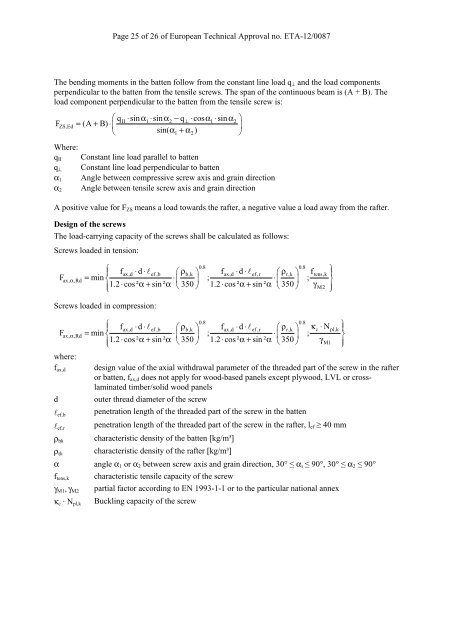
Page 25 of 26 of <strong>European</strong> <strong>Technical</strong> <strong>Approval</strong> no. <strong>ETA</strong>-<strong>12</strong>/<strong>0087</strong><br />
The bending moments in the batten follow from the constant line load q⊥ and the load components<br />
perpendicular to the batten from the tensile screws. The span of the continuous beam is (A + B). The<br />
load component perpendicular to the batten from the tensile screw is:<br />
⎛ qII ⋅sin α1 ⋅sin α2 − q⊥ ⋅cos α1 ⋅sin α2<br />
⎞<br />
F ZS,Ed = (A + B) ⋅⎜ ⎟<br />
⎝ sin( α 1 + α2<br />
) ⎠<br />
Where:<br />
qII Constant line load parallel to batten<br />
q⊥ Constant line load perpendicular to batten<br />
α1 Angle between compressive screw axis and grain direction<br />
Angle between tensile screw axis and grain direction<br />
α2<br />
A positive value for FZS means a load towards the rafter, a negative value a load away from the rafter.<br />
Design of the screws<br />
The load-carrying capacity of the screws shall be calculated as follows:<br />
Screws loaded in tension:<br />
0.8 0.8<br />
⎧<br />
⎪ fax,d ⋅ d ⋅ lef ,b ⎛ ρb,k ⎞ fax,d ⋅d ⋅ lef<br />
,r ⎛ ρr,k<br />
⎞ f ⎫<br />
tens,k ⎪<br />
Fax, α,Rd<br />
= min ⎨ ⋅⎜ ⎟ ; ⋅⎜<br />
⎟ ; ⎬<br />
⎪1.2 ⋅cos² α + sin ² α ⎝ 350 ⎠ 1.2 ⋅cos ² α + sin ² α ⎝ 350 ⎠ γ<br />
⎩ M2 ⎪⎭<br />
Screws loaded in compression:<br />
0.8 0.8<br />
⎧<br />
⎪ fax,d ⋅d ⋅l ef ,b ⎛ ρb,k ⎞ fax,d ⋅ d ⋅ lef<br />
,r ⎛ ρr,k<br />
⎞ κc ⋅ N ⎫<br />
pl,k ⎪<br />
Fax, α,Rd<br />
= min ⎨ ⋅⎜ ⎟ ; ⋅⎜<br />
⎟ ; ⎬<br />
⎪1.2 ⋅cos² α + sin ² α ⎝ 350 ⎠ 1.2⋅ cos² α + sin ² α ⎝ 350 ⎠ γ<br />
⎩ M1 ⎪⎭<br />
where:<br />
fax,d<br />
design value of the axial withdrawal parameter of the threaded part of the screw in the rafter<br />
or batten, fax,d does not apply for wood-based panels except plywood, LVL or crosslaminated<br />
timber/solid wood panels<br />
d outer thread diameter of the screw<br />
lef,b<br />
lef,r<br />
ρb�k<br />
ρr�k<br />
penetration length of the threaded part of the screw in the batten<br />
penetration length of the threaded part of the screw in the rafter, lef ≥ 40 mm<br />
characteristic density of the batten [kg/m³]<br />
characteristic density of the rafter [kg/m³]<br />
α angle α1 or α2 between screw axis and grain direction, 30° ≤ α� ≤ 90°, 30° ≤ α2 ≤ 90°<br />
ftens,k<br />
γM1, γM2<br />
κc · Npl,k<br />
characteristic tensile capacity of the screw<br />
partial factor according to EN 1993-1-1 or to the particular national annex<br />
Buckling capacity of the screw