AHG Solutions Guide_Edition 2.7
Full Product and Solutions Guide - Automatic Heating Global Pty Ltd
Full Product and Solutions Guide - Automatic Heating Global Pty Ltd

Create successful ePaper yourself
Turn your PDF publications into a flip-book with our unique Google optimized e-Paper software.
<strong>Solutions</strong> <strong>Guide</strong> <strong>Edition</strong> <strong>2.7</strong>
Contents<br />
Contents<br />
Contents<br />
Company Overview 2<br />
The Automatic Heating Advantage 4<br />
Sales & Technical Support 6<br />
Service & Maintenance 8<br />
Heat Pumps 10<br />
Air to Water Heat Pumps 11<br />
Water to Water Heat Pumps 59<br />
Condensing & Conventional Boilers 66<br />
Condensing Boilers 67<br />
Conventional Boilers 113<br />
Gas, Dual Fuel & Oil Burners 125<br />
Flue Systems 137<br />
Biomass Boilers 152<br />
Wood Boilers 154<br />
Pellet Boilers 160<br />
Expansion & Deaeration 164<br />
Expansion Tanks & Pressurisation Systems 165<br />
Dirt and Air Separation 189<br />
Backflow Prevention & Water Makeup 217<br />
Thermal Storage 222<br />
Hot Water Storage Tanks for Domestic Water 224<br />
Buffer Storage Tanks for Heating and Cooling 238<br />
HVAC Pumps 246<br />
Saer Pumps 248<br />
Wilo Pumps 250<br />
Grundfos Pumps 252<br />
Inertia Bases 256<br />
HVAC Accessories 258<br />
Condensate Neutralisers 260<br />
Hydraulic Separators 266<br />
Heat Exchangers 268<br />
Valves and Gauges 270<br />
Water Treatment Products 278<br />
Prefabrication 282<br />
1
Company Overview<br />
Contents<br />
Company Overview<br />
Automatic Heating takes a whole-of-life, holistic<br />
approach to the manufacture, supply and service<br />
of our comprehensive range of water-based<br />
heating and cooling solutions.<br />
Our success is built on this approach, coupled with a thorough understanding of mechanical engineering<br />
principles and customer focus that has evolved through 90 years of experience in this technically<br />
demanding and rapidly changing industry.<br />
We offer system solutions in their entirety, meaning all components can be selected from one convenient<br />
trusted source. Importantly, this full product range is supported by Automatic Heating’s dedicated presales<br />
and after-sales support capability, and nationwide service network.<br />
Our Vision<br />
To offer each client an irrefutable case for energy efficient<br />
systems, which are integrated and attainable, high quality<br />
and sustainable, with numerous benefits demonstrable<br />
through advanced technical specification services and<br />
generously shared expertise.<br />
We have been challenging<br />
ourselves for over 90 years<br />
to find the most energyefficient<br />
way to achieve our<br />
mission, and will never stop<br />
perfecting this pursuit.<br />
Our Mission<br />
Our business exists to create comfort; in warmth that<br />
consoles, calms, relaxes and heals, and through cooling<br />
that soothes the body and mind. We sell complex<br />
products and execute advanced technical planning, for<br />
the purpose of achieving simple feelings that often go<br />
unnoticed. But that, in itself, is the mission, for when our<br />
work goes unnoticed, that is when we know we have<br />
succeeded in providing effective solutions that create the<br />
perfect indoor environment.<br />
We have been challenging ourselves for over 90 years<br />
to find the most energy-efficient way to achieve our<br />
mission, and will never stop perfecting this pursuit. As<br />
a family business, it is our personal mission to provide<br />
quality innovation through professional support and<br />
impeccable service to the Mechanical Services and<br />
Hydronic Heating Industries, which make our mission<br />
achievable.<br />
2
Contents<br />
Company Overview<br />
Our Purpose<br />
Automatic Heating Global’s purpose is to design, deliver<br />
and maintain sustainable, energy efficient solutions that<br />
enables others to live and work well.<br />
Our Brands<br />
Our Values<br />
• Help from the heart<br />
• Solve it for the Customer<br />
• Trust is Fundamental<br />
• Champion Sustainability<br />
• Show initiative<br />
Automatic Heating is pleased to represent the following global brands. As<br />
leading forces for quality and innovation in the commercial HVAC sector for<br />
many years, these trusted manufacturers continue to open up new horizons in<br />
heating and cooling technology and sustainability.<br />
3
The Automatic Heating Advantage<br />
Contents<br />
The Automatic<br />
Heating Advantage<br />
Automatic Heating’s Revere CO 2<br />
Heat Pumps bring an exciting and promising aspect of non-fossil fueled<br />
sustainable high temperature hot water heating to the commercial HVAC market in Australia.<br />
Here For The Long Haul<br />
Since our beginnings in a small<br />
workshop in Park Street, South<br />
Melbourne in 1926, Automatic<br />
Heating has evolved into a truly<br />
innovative, national company.<br />
Now in our fourth generation,<br />
Automatic Heating continues to be<br />
synonymous with the strengths that<br />
have made us who we are today:<br />
first-class engineering, friendly<br />
customer service based on a sound<br />
understanding of the underlying<br />
technology and a passion for<br />
innovation and sustainability.<br />
We continue to increase our<br />
competitiveness through state-ofthe-art<br />
production methods, ongoing<br />
product development and processoriented<br />
management – opening up<br />
the markets of the future with a longterm,<br />
solution-based approach.<br />
Sustainable Integrated <strong>Solutions</strong><br />
Our vision is to be the leading provider<br />
of innovative and energy efficient<br />
products to the Australian HVAC<br />
industry, with a strong emphasis<br />
on sustainability to help customers<br />
reduce their carbon footprint.<br />
The best way to achieve a sustainable<br />
result is to design integrated solutions<br />
that are energy efficient in all facets of<br />
their construction. Our product range<br />
reflects this, with integrated solutions<br />
offered in their entirety from one<br />
convenient source.<br />
Each product we stock is a leader<br />
in its category, sourced globally<br />
from some of the most progressive<br />
and technologically advanced<br />
manufacturers in the world.<br />
Even though these products may<br />
have been tried and tested in some<br />
of the world’s most demanding<br />
environments, Automatic Heating<br />
ensures they are suited to Australian<br />
conditions and certified where<br />
necessary, giving you complete<br />
confidence that you are investing in<br />
proven, leading-edge technology of<br />
unrivalled quality.<br />
At Automatic Heating, we would like<br />
to see your next HVAC project go<br />
down in history as a shining example<br />
of innovation, exemplary design and<br />
sustainability. We invite you to partner<br />
with us to promote sustainable climate<br />
mechanics and help shape a brighter<br />
and more sustainable future.<br />
Let’s work together now for<br />
a better future<br />
4
Contents<br />
The Automatic Heating Advantage<br />
Expert design<br />
and technical support<br />
Extensive stock<br />
holding facilities<br />
Comprehensive<br />
Product Range<br />
As the leading provider of Waterbased<br />
Heating & Cooling to the<br />
Commercial HVAC market across<br />
Australia, Automatic Heating is able to<br />
provide superior design and technical<br />
support to ensure that our products<br />
meet or exceed your specifications.<br />
We also provide support in the<br />
commissioning and certification of<br />
products from relevant authorities.<br />
Our products are easy for you to<br />
specify, or we can assist you. We<br />
take care to ensure our advanced<br />
specification and design services will<br />
add value to our client’s offering and<br />
optimise the project outcome.<br />
The knowledge and experience of four<br />
generations is at your disposal when<br />
working with Automatic Heating.<br />
Automatic Heating maintains an<br />
extensive range of stock products<br />
including a vast range of spare parts<br />
to support and meet your project<br />
requirements.<br />
With nearly 3,000m2 of warehousing<br />
we carry an extensive inventory<br />
– from the smallest fittings to the<br />
largest boilers.<br />
Our head office is located within<br />
the Northpoint Enterprise Park in<br />
Melbourne’s northern suburbs.<br />
We are closely positioned to major<br />
arterial roads and are only 20<br />
minutes from the Melbourne CBD.<br />
Automatic Heating maintains an<br />
extensive range of stock products<br />
including a vast range of spare<br />
parts to support and meet your<br />
project requirements.<br />
Regularly searching the globe for<br />
the newest and most innovative<br />
products, we can assist in the design<br />
of integrated systems for your next<br />
project, saving you time and effort by<br />
providing the best equipment for the<br />
job from a single reliable source.<br />
• CO2 High Temperature Heat Pumps<br />
• Condensing and Conventional<br />
Boilers<br />
• Gas, Oil And Dual Fuel Burners<br />
• Flue Systems<br />
• Biomass Boilers<br />
• Expansion Tanks & Deaeration<br />
Systems<br />
• Dirt and Air Separation<br />
• Backflow Prevention<br />
• Thermal Storage<br />
• HVAC Pumps<br />
• HVAC Accessories<br />
Warranty Commitment<br />
All our products come with a<br />
minimum 12-month warranty<br />
commitment*, with full access to the<br />
Service Department who can manage<br />
the ongoing wellbeing of the system.<br />
* Warranties of up to 10 years apply to some products -<br />
conditions apply<br />
5
Sales & Technical Support<br />
Contents<br />
Sales & Technical<br />
Support<br />
Our products may be easy to specify but<br />
we understand the limited resources,<br />
tight deadlines, and cost pressures our<br />
customers face on a daily basis.<br />
Hence, our experienced sales and technical support<br />
staff are available to provide technical advice as well as<br />
advanced specification and design services to help you<br />
make the right choice every time.<br />
Then we’ll be as hands-on as required through<br />
installation and commissioning to ensure your<br />
investment operates efficiently from day one.<br />
The desired result is project outcomes that maximise<br />
ease of installation, operational performance and energy<br />
efficiency for the benefit of the environment, the project,<br />
the client and the HVAC industry.<br />
We believe in creating genuine relationships with clients,<br />
which we maintain through consistently adding value<br />
in the form of expert advice, technical support, quality<br />
products, innovation and flexibility.<br />
Automatic Heating are here & always willing<br />
to offer solutions to solve any project demand.<br />
Speak to us today about your next project.<br />
Our technical team can offer specialist advice,<br />
making your life a lot easier.<br />
6
Contents<br />
Sales & Technical Support<br />
Complimentary Services<br />
We offer the following complimentary services to any<br />
professional involved in designing or building sustainable,<br />
comfortable indoor environments for the Australian<br />
community.<br />
• Quotations for project budgeting<br />
• Payback calculations<br />
• Technical advice<br />
• System design advice<br />
• Product selections<br />
• Product specifications<br />
• Energy efficiency modelling<br />
• System schematic drawings<br />
• DWG/Revit drawings<br />
• On-site assessments, recommendations and troubleshooting<br />
• In-house technical training presentations<br />
• Product display and showrooms<br />
• Technical information webinars<br />
CAD Drawings<br />
To ensure clients obtain maximum value from this service, it is<br />
important to provide as much detail as possible, including:<br />
• Existing plantroom conditions including room size and<br />
placement of existing equipment and services<br />
• The new equipment that is required to be accommodated in<br />
the plantroom<br />
• Any access considerations or contingencies applicable to the<br />
plantroom or building<br />
Our Technical Manager is available to assist you with any<br />
queries and can arrange a site visit if necessary.<br />
48-Hour ‘SpecTech’ Service<br />
From the moment we receive your enquiry we work hard to<br />
ensure you get a response containing specification details,<br />
technical information, and budget costs, all within 2 working<br />
days.<br />
Face-to-Face Visits<br />
The friendly team members at Automatic Heating are happy<br />
to visit you at your office or on-site to work collaboratively<br />
in finding the most appropriate solution for your needs and<br />
budget.<br />
Training & Product Demonstrations<br />
Our DWG drawings and revolutionary Revit drawings offer<br />
you greater insight into your chosen products and how they<br />
interact with one another in a HVAC system. Our expert team<br />
can assess the system schematic with you and offer helpful<br />
advice to ensure the success of your project.<br />
Mechanical Plantroom Design and Layout<br />
Automatic Heating Technical Staff are available to<br />
provide training and product demonstrations to our<br />
clients and consultants at their premises or at a<br />
convenient conference venue. We also cater for morning<br />
tea or lunchtime technical presentations.<br />
Contact Automatic Heating on 03 9330 3300 for further<br />
information or to arrange a visit from one of our<br />
Technical Sales Specialists.<br />
Planning is crucial to any project and when space or access<br />
is limited, it becomes even more important. Automatic<br />
Heating have the capacity to provide technical drawings and<br />
3D renders to assist in visualisation and space optimisation<br />
of your plantroom design.<br />
7
Service & Maintenance<br />
Contents<br />
Service & Maintenance<br />
Take our word for it ....<br />
Prevention is better than Cure<br />
The old adage “a stitch in time, saves nine” is an<br />
understatement in the context of boiler maintenance.<br />
With boilers often in constant service and fulfilling critical<br />
heating functions within buildings ranging from domestic<br />
residences to major airports, it makes sense to keep them<br />
running at peak performance. Unfortunately, all too often,<br />
boiler maintenance remains unscheduled and overlooked<br />
until boiler failure becomes a reality and a lack of heating<br />
starts impacting on people and critical functions throughout<br />
the household or organisation.<br />
Annual Service<br />
Every boiler, cooler and pump requires maintenance to<br />
ensure reliable and efficient operation. An un serviced<br />
system can quickly become a costly asset, experiencing<br />
premature failures that can damage both the system and<br />
potentially the surrounding areas. Regular preventative<br />
maintenance will ensure optimum performance is being<br />
achieved and running costs are being kept to a minimum.<br />
Our nationwide service network offers fixed price,<br />
tailored service contracts to allow you to budget for the<br />
maintenance of your plant with confidence, while our<br />
extensive range of spare parts can be relied upon at any<br />
time - even long after your purchase. Tailored service<br />
contracts mean that you only pay for the level of servicing<br />
you require and the fixed price enables you to budget for the<br />
cost of the plant over the coming years.<br />
Key reasons for having your boiler serviced annually<br />
1. Regulatory Compliance – Government regulations set<br />
out minimum service requirements for all commercial<br />
buildings in order to meet health and safety standards.<br />
These regulations also stipulate how long service<br />
records should be kept. Annual servicing of your<br />
heating plant and maintenance of accurate service<br />
records provides a level of insurance not only against<br />
heating failure but against costly litigation resulting<br />
from an appliance rendered dangerous through<br />
neglect.<br />
2. Keeping your building safe – Having your boiler<br />
serviced helps to highlight any potential dangers and<br />
risks associated with your boiler and flue. When your<br />
boiler stops working efficiently, it’s possible for toxic<br />
carbon monoxide gases to be released. These gases<br />
are extremely dangerous and pose serious risks to<br />
anyone exposed to them, yet are ordinarily hard to<br />
detect.<br />
3. Identify Problems Early – During a service, potential<br />
problems are identified early and can help to minimise<br />
further damage to the boiler and save costly future<br />
repairs.<br />
4. Reduce your Fuel Bills – During an annual boiler<br />
service, your boiler parts are cleaned and the boiler<br />
efficiency is checked. A properly maintained boiler<br />
running at optimum efficiency ensures ongoing energy<br />
savings are maintained.<br />
8
Contents<br />
Service & Maintenance<br />
5. Keeping your Warranty Valid – Many boiler warranties<br />
are valid subject to having an annual service carried<br />
out. For many boiler manufacturers, failing to service<br />
your boiler using an appropriately certified heating<br />
engineer can invalidate your warranty altogether,<br />
leaving you liable for costly repair bills.<br />
6. Cheaper than Replacing a Boiler – If your boiler is<br />
left faulty for long periods of time, much larger and<br />
more complicated issues can arise, perhaps even<br />
resulting in your boiler needing replacing. Recognising<br />
any problems early on can reduce the amount of<br />
permanent damage caused to your boiler and keep it<br />
running for longer.<br />
Commissioning<br />
Once a system is engineered and installed, essential<br />
checks should be made to ensure maximum safety from<br />
the very start. The Automatic Heating commissioning<br />
service involves checking that your systems have been<br />
installed correctly as specified and includes various<br />
testing procedures to ensure satisfactory performance and<br />
compliance with appropriate regulations.<br />
The commissioning process is the most important part<br />
of any installation before it is set into full operation. In<br />
addition, the Automatic Heating team can also program your<br />
system, set it up and, where required, train your operator.<br />
On Site Inspection and Audit<br />
Where needed, we can organise one of our experts to<br />
perform an on site inspection and audit. This will provide<br />
you with a report on our findings and a recommendation on<br />
which step to make next, whether it be maintenance, repair<br />
or replacement of your equipment.<br />
Repairs<br />
Qualified Technicians<br />
It is important that whoever services your boiler is suitably<br />
qualified, experienced and equipped with the parts needed<br />
to complete the service. This minimises costs and downtime<br />
and ensures warranties remain valid. Automatic Heating<br />
technicians are fully trained and qualified to service our<br />
equipment and their fully stocked vans carry the parts<br />
needed to complete each job.<br />
Their professional competence and high level of practical<br />
and diagnostic experience means you can be assured your<br />
products are always running at optimum performance<br />
when maintained by the Automatic Heating Service Team.<br />
Support anytime, anywhere<br />
Our service technicians are available for emergency callouts<br />
and frequently provide support to clients in remote<br />
areas.<br />
From our Melbourne Head Office, our Operation and<br />
Maintenance Department uses state of the art technology to<br />
remotely monitor our O&M sites - as well as offering email,<br />
SMS and mobile notification to ensure online operation for<br />
your total peace of mind.<br />
The Automatic Heating Service team is available to repair<br />
your system even outside of the warranty period.<br />
Our highly responsive technicians are trained in all areas<br />
and applications of the most technical of systems with the<br />
ability to quickly diagnose and fix problems on site, in most<br />
situations. We understand every minute of downtime is a<br />
cost to a business which is why we do everything possible<br />
to provide a solution, even if it is an interim measure to get<br />
your system back up and running as quickly as possible.<br />
Parts & Consumables<br />
We maintain an extensive range of genuine spare parts for<br />
all commercial boilers, cooling systems, water heaters and<br />
pressurisation units, to ensure our technicians can respond<br />
quickly to our client’s servicing needs.<br />
Your spare parts from Automatic Heating have quality<br />
assurance conformity and carry a 12 month warranty. Using<br />
genuine parts means you benefit from any technological<br />
improvements that may have been made as part of our<br />
policy of continuous product improvement. We are always<br />
looking to make our commercial heating, cooling and hot<br />
water products even more efficient.<br />
9
HEAT PUMPS<br />
Heat Pumps<br />
Contents<br />
10
Contents<br />
Air to Water<br />
Heat Pumps<br />
Air to Water Heat Pumps<br />
HEAT PUMPS<br />
Air to Water Heat Pumps offer unrivaled efficiencies of up to 350%.<br />
Air to Water Heat Pumps can provide efficient heating and cooling for your home or<br />
commercial building, especially if you live in a warm to moderate climate. An air to water<br />
heat pump can deliver from 1.5 to 3 times more thermal energy to a building than the<br />
electricity it uses. This can happen due to the fact that the heat pump transfers heat, rather<br />
than transforming it from a type of fuel like regular combustion heating systems do.<br />
CO 2<br />
Heat Pumps<br />
R32 Heat Pumps<br />
Revere CO 2<br />
15-66.4kW pg 12<br />
Revere R32 Inverter pg 22<br />
R410A Heat Pumps<br />
Revere R410A Inverter pg 23 Revere R410A pg 26<br />
Galleti MPI DC 8-29kW pg 30<br />
Galleti MPE 4-76kW pg 34 Galleti HiRef HPS 43-216kW pg 42 Galleti EvitecH 50-180kW pg 46<br />
Galleti SCX 80-360kW pg 52<br />
11
HEAT PUMPS<br />
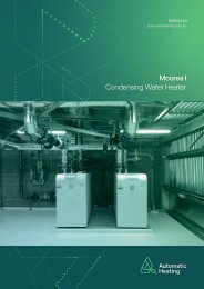
Revere CO 2 - Air to Water Heat Pumps<br />
Revere CO 2<br />
Air to Water Heat Pumps<br />
A Sustainable Technology<br />
Regardless of political agendas or incentives, consumers worldwide are<br />
increasingly pursuing sustainable, cost effective alternatives to traditional fossil<br />
fuelled equipment for their hot water and space heating requirements. Using<br />
natural CO 2<br />
as the refrigerant and achieving a high coefficient of performance<br />
(COP), CO₂ heat pumps offer both ecological and financial benefits.<br />
Contents<br />
The unique capacity of the Revere CO 2<br />
Heat Pump to<br />
produce 90°C hot water makes it suitable for use in a wide<br />
range of industrial, commercial and residential projects,<br />
including food processing plants, dairies, shopping centres,<br />
apartments, hotels, restaurants, hospitals, aged care,<br />
recreational and educational facilities. Revere can also<br />
be adopted with a high level of safety as the absence of<br />
combustion reduces the risk of fire.<br />
Instead of the more conventional ammonia or haloalkane<br />
(R134A) refrigerant gases, Revere CO 2<br />
Heat Pumps use<br />
supercritical carbon dioxide as the refrigerant.<br />
The technology offers a means of energy conservation and<br />
reduces the emission of greenhouse gas.<br />
From the energy output side, the operational characteristics<br />
of the heat pump are different to conventional systems<br />
(such as electric/gas/oil boilers or electric heaters). With<br />
conventional systems, 1kW input of energy provides less<br />
than 1 kW of output energy or heat. With a CO 2<br />
heat pump<br />
system, every 1kW of input energy consumed produces<br />
an average of 3.9 x the input as output energy or heat by<br />
extracting heat from the outside air.<br />
Summary<br />
Producing 90°C hot water with an average COP of 3.9,<br />
makes Revere CO₂ Heat Pumps an ideal energy efficient<br />
domestic hot water and space heating system for industrial,<br />
commercial and residential applications. This ability to<br />
convert 1kW of input energy into 3.9kW of output energy<br />
represents an ongoing economical and sustainable water<br />
heating solution.<br />
About Itomic Nihon<br />
Itomic Nihon has been a leading manufacturer of hot<br />
water heaters in Japan since 1948. With over 2500 Itomic<br />
Revere CO 2<br />
Heat Pumps installed globally, this product<br />
continues to demonstrate its worth as a proven and reliable<br />
non-fossil fuel water heating system.<br />
12
Contents<br />
Revere CO 2<br />
- Air to Water Heat Pumps<br />
Revere CO 2 Heat Pump Features & Advantages<br />
HEAT PUMPS<br />
Heats up to 90°C - Due to its innovative design, the<br />
Revere CO 2<br />
Heat Pump can produce hot water up to 90°C<br />
at low and high ambient temperatures (-20°C to 43°C)<br />
Flexible - The same system can be simultaneously used for<br />
Space Heating & Domestic Hot Water<br />
Ultra quiet operation – 60dBa<br />
No combustion - reduces fire risk<br />
Suitable for up to 60°C ΔT (flow 90°C, return 30°C)<br />
Suits Australian conditions – accommodates ambient<br />
operating temperatures from -5°C to 43°C (Special unit<br />
available for -15°C or -20°C)<br />
Safe - Non-flammable CO₂ refrigerant<br />
Programmable – can be set to operate during off peak<br />
times to benefit from low cost power<br />
30% Space Saving due to Y Frame design (CHP-80)<br />
Versatile - Suitable for a wide range of purposes, from<br />
small facilities to large buildings where hot water or<br />
heating is required.<br />
Eco friendly - The Revere CO 2<br />
Heat Pump uses natural<br />
CO₂ refrigerant. This refrigerant has a global warming<br />
potential (GWP) of about 1/1700 that of R410 and zero<br />
ozone-depleting potential (ODP).<br />
Energy efficient - Under optimal conditions, Revere<br />
CO 2<br />
Heat Pumps achieve an exceptional coefficient of<br />
performance (up to 4.2) which equates to higher energy<br />
efficiency. Compared to the traditional electric hot water<br />
heater, the CO 2<br />
hot water heat pump can save up to 75%<br />
heating energy. Further energy cost savings can be<br />
achieved through operation during off peak hours, subject<br />
to off-peak electrical power supply.<br />
Anti-freeze/Cold Area Units - the heat pump is fitted with a<br />
defrost solenoid valve which will open when the evaporator<br />
ices up. The hot gas will then flow through the evaporator<br />
and melts the ice. Water cannot be stored during defrosting.<br />
One pass heating - It is suitable for heating water from low<br />
to high temperatures (large temperature difference) in one<br />
pass.<br />
Reduces storage requirements - Since this hot water heat<br />
pump can heat water up to 90ºC, the size of the storage tank<br />
can be reduced.<br />
Volume of hot<br />
water used (L)<br />
Calculated necessary<br />
volume of hot water (L)<br />
Monday<br />
Necessary hot water volume and operating<br />
time calculated from 4 weeks of operation data<br />
Tuesday Wednesday Thursday Friday Saturday Sunday<br />
Week 1<br />
Week 2<br />
Week 3<br />
Week 4<br />
Energy Saving Function - This function is an energy-saving<br />
function that learns operation patterns from the four previous<br />
weeks to prevent unnecessary heating and temperature<br />
decreases in stored water through natural heat loss. The use<br />
of this function based on operation data stops the unit from<br />
boiling water unnecessarily.<br />
Running Cost Comparison<br />
Cents / kwH<br />
7<br />
28 29.6<br />
APPROX<br />
1/4<br />
RUNNING COST<br />
Revere CO 2<br />
Heat Pump<br />
Electric Water<br />
Heater<br />
LPG<br />
Fueled Boiler<br />
Revere offers Significantly lower running costs & CO₂ emissions<br />
13
HEAT PUMPS<br />
Revere CO 2<br />
- Air to Water Heat Pumps<br />
How It Works<br />
The Revere CO 2<br />
Hot water heat pump is an energy efficient electric heat pump that uses heat extracted<br />
from the air to heat water for industrial, commercial and residential applications. A hot water heat pump<br />
removes energy from a low temperature source (ambient air or waste water) and moves it to a high<br />
temperature hot water tank.<br />
Contents<br />
Heat<br />
pump<br />
unit<br />
Compressor<br />
Hot<br />
90°C<br />
Hot water<br />
supply<br />
Air<br />
Heat<br />
exchanger<br />
(for air)<br />
CO 2<br />
refrigerant<br />
cycle<br />
Heat exchanger<br />
(for water<br />
heating)<br />
Water is<br />
heated<br />
Sealed<br />
storage tank<br />
Hot water supply<br />
Heating<br />
Refrigerant flow<br />
Fan<br />
Cold<br />
Expansion valve<br />
Water pump<br />
Cold water<br />
supply<br />
Advantages of using CO 2<br />
as a refrigerant<br />
This heat pump uses CO₂ as a refrigerant. CO₂ is a natural refrigerant and has an ozone depletion<br />
potential (ODP) of zero and a global warming potential (GWP) of 1. CO 2<br />
refrigerant is a non HFC<br />
refrigerant. Traditional HFC refrigeration systems affect climate change in two distinct ways: direct and<br />
indirect contribution. Direct contribution results from the release of refrigerants into the atmosphere.<br />
Indirect contribution refers to the energy used to operate traditional refrigeration equipment. The less<br />
energy required to operate the equipment, the lower the impact on the environment.<br />
Refrigerant Characteristics<br />
HFC<br />
Natural Refrigerant<br />
Refrigerant<br />
R410A R407C R744(CO 2<br />
)<br />
Ozone depletion potential 0 0 0<br />
Global warming potential 1975 1653 1<br />
Combustible No No No<br />
Toxicity Low Low Low<br />
14
Contents<br />
Revere CO 2<br />
- Air to Water Heat Pumps<br />
HEAT PUMPS<br />
CHP-15HF<br />
CHP-26H4<br />
CHP-080Y2<br />
General Performance Data of a Standard Unit<br />
Product Code<br />
Power supply<br />
Total power input@ 25ºC<br />
ambient(kW)<br />
Heating output @ 25ºC<br />
ambient (kW)<br />
Average COP*<br />
Dimension<br />
L x W x H(mm)<br />
CHP-15F 3 phase 415V/50Hz 4.16 15 4.0 900 x 450 x 1850<br />
CHP-26H4 3 phase 415V/50Hz 6.7 29.3 3.9 1300 x 890 x 1705<br />
CHP-080Y2 3 phase 415V/50Hz 18.8 78.4 3.8 1790 x 1010 x 2000<br />
* Average COP based on constant hot water supply at 65ºC and ambient temperature range of -7ºC to 43ºC.<br />
CO2 heat pump system for<br />
DHW and space heating on<br />
skid frame.<br />
15
HEAT PUMPS<br />
Revere CO 2<br />
- Air to Water Heat Pumps<br />
Designed for Space and Energy Efficiency<br />
With a heating performance of 80 kW, the<br />
CHP-080Y2 was developed to reduce high<br />
hot water supply costs and large space<br />
requirements that inevitably occur in facilities<br />
requiring a large hot water supply.<br />
The structure of the Y-shaped frame reduces<br />
power consumption and allows units to<br />
be installed close together. The heating<br />
performance can be switched between three<br />
modes in order to adjust the energy to suit<br />
how you use hot water, and performance does<br />
not decrease* in temperatures down to -15°C.<br />
This flexible system is suitable for a wide<br />
range of facilities that use large volumes of<br />
hot water, and is durable enough to provide a<br />
steady hot water supply for a long time.<br />
* Energy-saving mode only<br />
Contents<br />
Product Quick Check<br />
Type<br />
CO₂ Heat Pump<br />
Range<br />
12-80kW<br />
Efficiency Average COP 3.9<br />
Fuel Type Electricity<br />
Outdoor option Yes<br />
Cascadeable<br />
Max Pressure<br />
Zero Nox<br />
Building J Code<br />
2018 compliant<br />
Yes<br />
490 kPa<br />
Yes<br />
Yes<br />
16
Contents<br />
Performance Data<br />
Revere CO 2<br />
- Air to Water Heat Pumps<br />
HEAT PUMPS<br />
Product Code<br />
Constant Supply Hot Water at 65°C<br />
Heating Ability<br />
kW<br />
A / B / C*<br />
Storage Capacity<br />
L/h<br />
A / B / C*<br />
Supply Water → Hot Water<br />
°C<br />
A / B / C*<br />
Power Consumption<br />
Kw<br />
A / B / C*<br />
Average COP<br />
CHP-15F 15 / 15 / 15 230 / 269 / 315 9→65 / 17→65 / 24→65 3.6 / 3.4 / 3.13 4.2<br />
CHP-26H4 24.0 / 26.3 / 29.3 369 / 471 / 615 9→65 / 17→65 / 24→65 6.20 / 6.55 / 6.70 3.9<br />
CHP-080Y2 61.1 / 65.6 / 66.4 938 / 1175 / 1392 9→65 / 17→65 / 24→65 16.1 / 16.1 / 14.9 3.6<br />
Product Code<br />
Constant Supply Hot Water at 90°C<br />
Heating Ability<br />
kW<br />
A / B / C*<br />
Storage Capacity<br />
L/h<br />
A / B / C*<br />
Supply Water → Hot Water<br />
°C<br />
A / B / C*<br />
Power Consumption<br />
Kw<br />
A / B / C*<br />
Average COP<br />
CHP-15F 15 / 15 / 15 159 / 177 / 177 9→90 / 17→90 / 24→90 4.68 / 4.48 / 4.16 4.2<br />
CHP-26H4 24.5 / 25.5 / 27.0 260 / 300 / 352 9→90 / 17→90 / 24→90 7.40 / 7.50 / 7.80 3.9<br />
CHP-080Y2 58.9 / 63.9 / 6<strong>2.7</strong> 625 / 752 / 817 9→90 / 17→90 / 24→90 18.3 / 19.3 / 17.8 3.6<br />
* Ambient Temperatures - A: DB7°C / WB6°C (Winter) - B: DB16°C / WB12°C (Intermediate) - C: DB25°C / WB21°C (Summer)<br />
Specifications<br />
Product Code CHP-15F CHP-26H4 CHP-080Y2<br />
Power Supply<br />
Design pressure at refrigerant<br />
side<br />
MPa<br />
Low pressure side 8 / High pressure<br />
side 13.2<br />
3 phase 415V 50Hz<br />
Low pressure side 7.5 / High pressure side 14<br />
Compressor Type Horizontal scroll compressor Semi-hermetic reciprocating compressor<br />
Compressor Motor Type<br />
Three-phase induction motor<br />
Inverter drive three-phase induction<br />
motor<br />
Compressor Rated Output kW 1.9kW x 2 8.4 15.8<br />
Crankcase Heater W N/A 100 140<br />
Fan W Propeller fan (47Wx2) Propeller fan (110Wx2) Propeller fan (300Wx2)<br />
Pump W 30 Seal-less, AC200V - 100W Seal-less, DC282V - 140W<br />
Air heat exchanger<br />
Protection Devices<br />
Supply hot water heat exchanger<br />
High pressure switch<br />
High·low pressure sensor<br />
Fuse (fan & pump)<br />
Forced cooling cross fin<br />
Compressor motor excessive temperature protection<br />
Compressor rupture disk<br />
Over current relay (compressor)<br />
Forced circulation double-piping type<br />
High pressure switch<br />
High·low pressure sensor<br />
Compressor over heat<br />
cut out device<br />
Compressor pressure<br />
relief valve<br />
Over current relay (fan)<br />
Over current protection<br />
Refrigerant / filling volume kg CO 2<br />
(R744)/ 2 x 1.18 CO 2<br />
(R744)/ 6.8 CO 2<br />
(R744)/ 11.3<br />
Dimensional Data<br />
Product Code<br />
Dimensions<br />
H x W x D<br />
Product mass/Operating weight<br />
kg<br />
CHP-15F 1850 x 900 x 450 174 / 177<br />
CHP-26H4 1705 x 1300 x 890 480 / 500<br />
CHP-080Y2 2000 x 1790 x 1010 690 / 710<br />
17
HEAT PUMPS<br />
Revere CO 2<br />
- Air to Water Heat Pumps<br />
CHP-15F Dimensional Data and Installation <strong>Guide</strong><br />
Contents<br />
Dimensions<br />
Operation output, Error output, External input terminal board<br />
Terminal - Remote controller, HP communication×2<br />
Supply hot water stop valve terminal board<br />
Power source terminal board<br />
Air discharge outlet<br />
Grounding terminal<br />
(Inside the electric device BOX)<br />
Air suction inlet<br />
91 for rear leg<br />
Heat pump outlet piping (B side) connection (R3/4)<br />
Heat pump intlet piping (A side) connection (R3/4)<br />
91 for rear leg<br />
Grounding<br />
Drain piping connection for venting air (R1/2)<br />
terminal<br />
(Make sure the connection for the possible successive drainage)<br />
Anchor bolt position, Piping connection (Top view)<br />
Product mass<br />
Operating<br />
weight<br />
Drain hole (<br />
35 hole)<br />
Remote control cord & others lead-in position<br />
Connection for heat pump outlet piping (B side)<br />
Connection for heat pump inlet piping (A side)<br />
Power cable lead-in position<br />
Connection for air vent drain piping<br />
Use four M12 anchor bolts with the<br />
buried length of more than 60mm<br />
Drain hole (<br />
20 hole)<br />
Anchor bolt notch hole<br />
(M21 for bolt×4 spots)<br />
Installation <strong>Guide</strong>lines<br />
FRONT VIEW SHOWING FRONT VIEW TOP SPACE SHOWING TOP SPACE<br />
REQUIRED FOR REQUIRED MAINTENANCE FOR MAINTENANCE<br />
PLAN VIEW SHOWING PLAN VIEW SHOWING • This unit is not for indoor<br />
CLEARANCE SPACES CLEARANCE REQUIRED SPACES REQUIRED installation. Outdoor<br />
installation only.<br />
• Consult your sales store<br />
when obstacles are at three<br />
directions, and for a built-in<br />
installation.<br />
• Do not set this unit in a closed<br />
depression with all sides<br />
deeper than 1.0M<br />
ARROW DENOTES AIR ARROW INPUT DENOTES AIR INPUT<br />
AND OUTPUT DIRECTION AND OUTPUT DIRECTION<br />
18
Contents<br />
Revere CO 2<br />
- Air to Water Heat Pumps<br />
CHP-26H4 Dimensional Data and Installation <strong>Guide</strong><br />
HEAT PUMPS<br />
Dimensions<br />
100<br />
25<br />
A Anchor bolt fitting holes (4 Ø15 holes)<br />
B O peration check window (front)<br />
C External signal connection port (sensor, etc.,Ø 24 holes)<br />
D Power source port ( Ø39 hole)<br />
E C ontrol board position (front)<br />
F Hot water outlet Rc3/4 (20 A, C AC 406)<br />
G Supply water inlet Rc3/4 (20 A, C AC 406)<br />
H Air heat exchanger room drain Rc1 (25 A, C 3604BD)<br />
I Drain outlet Rc3/4 (20 A, C AC 406)<br />
143<br />
72<br />
Cover<br />
Internal operating section<br />
(shown with cover open)<br />
Remote control cord slot<br />
10 13<br />
(83.5) (29.8)<br />
(attachment pitch)<br />
(29.7)<br />
Remote control cord terminal strip<br />
2-M3 (included)<br />
Top view<br />
Dedicated Remote Control<br />
815<br />
80<br />
1300<br />
Air outlet<br />
Air outlet<br />
Air inlet<br />
Air inlet<br />
B<br />
F<br />
12<br />
1705<br />
1525<br />
C<br />
G<br />
H<br />
165<br />
350<br />
75<br />
75<br />
170<br />
70<br />
130<br />
860<br />
100<br />
195<br />
A<br />
900<br />
195<br />
I<br />
145<br />
890<br />
5<br />
1290 5<br />
E<br />
D<br />
155 900<br />
195<br />
5<br />
Left view<br />
Front view<br />
Back view<br />
Installation <strong>Guide</strong>lines<br />
TOP VIEW OF HEAT PUMP UNIT<br />
700 mm or more<br />
FRONT VIEW OF HEAT PUMP UNIT<br />
3 m or more<br />
• Install the heat pump unit outdoors, with<br />
adequate ventilation<br />
• Install in a location where cold air from the<br />
air outlets of the heat pump unit or operating<br />
sounds will not disturb neighbours, or take<br />
soundproofing measures.<br />
• The diagram shows the space required for<br />
maintenance and inspections. It may not<br />
be possible to perform maintenance or<br />
inspections without the necessary space.<br />
Make sure to leave sufficient space when<br />
designing the layout.<br />
Front of heat<br />
pump unit<br />
700 mm or more<br />
Pipe Slot<br />
19
HEAT PUMPS<br />
Revere CO 2<br />
- Air to Water Heat Pumps<br />
Contents<br />
CHP-080Y2 Dimensional Data and Installation <strong>Guide</strong><br />
Dimensions<br />
100<br />
25<br />
143<br />
72<br />
Internal operating section<br />
(shown with cover open)<br />
(83.5) (29.8)<br />
(attachment pitch)<br />
Cover<br />
(29.7)<br />
Remote control cord terminal strip<br />
2-M3 (included)<br />
Front<br />
Remote control cord slot<br />
Dedicated Remote Control<br />
10 13<br />
Air Outlet<br />
Air Outlet<br />
Air Suction Inlet<br />
Air Suction Inlet<br />
Air heat exchange<br />
room drain<br />
Rc1(25A)<br />
CAC406<br />
Operation Check Window<br />
(Front)<br />
Control Panel<br />
(Front)<br />
External Signal Connection<br />
(Ø Sensor 22 Holes,<br />
Ø Grommet 17 Holes)<br />
Remote Control Line Connection<br />
(Ø 22 Holes, Ø Grommet 17 Holes)<br />
Hot<br />
Water Inlet<br />
Rc1(25A)<br />
CAC406<br />
Cold<br />
Water Inlet<br />
Rc1(25A)<br />
CAC406<br />
Anchor bolt Mounting Hole<br />
(6 x Ø 15 Holes)<br />
Cable Connection<br />
(Ø 22 Holes, Ø Grommet 17 Holes)<br />
Power Connection<br />
(Ø 44 Holes, Ø Grommet 17 Holes)<br />
Remote Control Line Connection<br />
(Ø 22 Holes, Ø Grommet 17 Holes)<br />
Cable Connection<br />
(Ø 22 Holes, Ø Grommet 17 Holes)<br />
Power Connection<br />
(Ø 44 Holes Grommet, Ø 36 Holes)<br />
Drain Outlet<br />
Rc3/4(20A)<br />
CAC406<br />
Maintenance Window<br />
Distant Control Panel Connection<br />
(Ø 22 Holes, Ø Grommet 17 Holes)<br />
Distant Control Panel Connection<br />
(Ø 22 Holes, Ø Grommet 17 Holes)<br />
Bottom: External Signal Connection<br />
(Sensor Ø 22 Holes, Ø Grommet 17 Holes)<br />
Cross Section A-A<br />
Installation<br />
<strong>Guide</strong>lines<br />
3 m or<br />
more<br />
100 mm or more<br />
500 mm<br />
or more<br />
275 mm or more<br />
500 mm or more<br />
500 mm or more<br />
• Install the heat pump unit outdoors, with adequate ventilation<br />
• Install in a location where cold air from the air outlets of the heat pump unit or operating sounds will not<br />
disturb neighbours, or take soundproofing measures.<br />
• The diagram shows the space required for maintenance and inspections. It may not be possible to perform<br />
maintenance or inspections without the necessary space. Make sure to leave sufficient space when designing<br />
the layout.<br />
275 mm or more<br />
20
Contents<br />
Case Studies<br />
Revere CO 2<br />
- Air to Water Heat Pumps<br />
HEAT PUMPS<br />
Yarra’s Edge Tower 1<br />
1 x Revere CO 2<br />
Heat Pump<br />
At Yarra’s Edge Tower 1, one of<br />
Melbourne’s finest waterside highrise<br />
apartments, Automatic Heating<br />
installed a new and improved<br />
hybrid system that features a high<br />
efficiency heat pump, high efficiency<br />
condensing boilers and twin coil<br />
storage tanks. Two atmospheric<br />
500kW boilers used for domestic<br />
hot water were replaced with an<br />
Revere 15kW High Temperature<br />
CO2 Heat Pump, five Meridian 150kW<br />
condensing boilers and Plate Heat<br />
Exchangers. This hybrid solution<br />
ensures that the new system will<br />
run as efficiently, sustainably, and<br />
economically as possible.<br />
Williamstown<br />
Industrial Application<br />
2 x 15kW Revere CO 2<br />
Air to Water heat pumps<br />
2 x 400L Twin Coil Watermark<br />
Stainless Steel Tanks<br />
Prefab skid frame with above<br />
equipment provides 90°C hot water<br />
for industrial process applications.<br />
Monash University<br />
Clayton Campus<br />
James Gormley Bike<br />
Arrival Station<br />
1 x 15kW Revere CO 2<br />
Air to Water heat pump<br />
2 x 750L Twin Coil Watermark<br />
Stainless Steel Tanks<br />
Prefab skid frame with above<br />
equipment provides DHW for<br />
28 showers and hot water for<br />
hydronic heating<br />
21
HEAT PUMPS<br />
Revere R32 Inverter - Air to Water Heat Pumps<br />
Revere <br />
R32 Inverter<br />
Air to Water Heat Pump<br />
With the advanced new technology of<br />
an EVI DC Inverter, the Revere R32<br />
Inverter Air to Water Heat Pump can<br />
be used in extremely cold area for<br />
heating/cooling, hot water.<br />
Contents<br />
1315<br />
mm<br />
395<br />
mm<br />
1000 mm<br />
Condition Unit Heating Cooling<br />
Ambient Temp. (DB/WB) ºC 7/6 7/6 2/1 2/1 -7/-8 -7/-8 35/24<br />
Water Temp. (In/Out) ºC 30/35 50/55 30/35 50/55 30/35 50/55 12/7<br />
Capacity Range kW 6.0~20.0 5.5~18.0 5.5~17.0 5.5~15.0 4.6~14.5 4.5~14.0 4.2~14.0<br />
Power Input Range kW 1.5~5.0 2.0~7.5 1.5~5.0 2.2~7.4 1.5~5.0 2.2~7.3 1.8~7.5<br />
EVI DC Inverter Technology<br />
With advanced new technology of EVI DC Inverter, the<br />
unit is capable of producing 60ºC domestic hot water.<br />
And according to laboratory testing (basing on ErP test<br />
standard), the energy level can reach A++.<br />
Smart Colorful Touch Display<br />
R32 wire controller is with a 5-inch smart colorful touch<br />
display which is installed on the wall. Featuring 0.5ºC<br />
precise control, water temperature curve display, easy<br />
timing, one-key mute and more, it provides an easy and<br />
convenient user experience.<br />
Intelligent Defrosting<br />
Intelligent defrosting uses the pressure sliding defrosting<br />
technology to figure out the exact defrosting time and start<br />
pressure according to the real ambient temperature. It saves<br />
energy and makes the heat pump work in high efficiency.<br />
Model - <strong>AHG</strong> R32 AW Unit Value<br />
Frequency Hz 30~90<br />
ErP Level (35°C & 55ºC)<br />
A++<br />
Power Supply<br />
380~415V, 3N, 50/60Hz<br />
Electric Heater kW /<br />
Max. Running Current A 13.5<br />
Refrigerant Type<br />
R32<br />
Refrigerant Quantity kg 1.8<br />
Compressor Brand<br />
Panasonic<br />
Water Pump<br />
Grundfos<br />
Water Connection inch 1.2<br />
Water Flow m 3 /h 2.15<br />
Water Pressure Drop kPa 45<br />
Water Pump Head m 4<br />
DC Motor Quantity 2<br />
DC Motor Power Input (max/min) W 130/45<br />
DC Motor Speed (max/min) RPM 850/300<br />
Noise* dB(A) 55<br />
Net Weight kg 155<br />
Gross Weight kg 175<br />
Net Dimension (L x W x H) mm 1000 x 395 x 1315<br />
Shipping Dimension (L x W x H) mm 1070 x 415 x 1330<br />
Operation Ambient Temp. ºC -25~43<br />
Max. Outlet Water Temp. ºC 60<br />
* Noise test is based on JB/T4330-1999 at 1 meter distance.<br />
22
Contents<br />
Revere R410A Inverter<br />
Air to Water Heat Pumps<br />
Revere R410A Inverter - Air to Water Heat Pumps<br />
HEAT PUMPS<br />
Works efficiently with floor heating, water<br />
fan coils or radiators for heating, cooling and<br />
sanitary hot water.<br />
Features<br />
Smart Colorful Touch Display<br />
5” smart colorful touch display which is installed on the wall.<br />
Applicable to RS485 communication, it is easy & convenient to<br />
operate.<br />
MITSUBISHI Compressor<br />
This range features Mitsubishi compressors for reliable operation<br />
and optimum performance.<br />
Riffled Copper<br />
Tube<br />
Gas Refrigerant<br />
Shell<br />
Cooling Water<br />
Liquid Refrigerant<br />
5.0MPa<br />
Pressure Test<br />
No welding point inside<br />
the water coil,<br />
no refrigerant leakage.<br />
Louvred Fins<br />
Spiral copper coil enlarges the water heat exchanging area<br />
so that the water can sufficiently exchange heat with gas.<br />
Finned Heat Exchanger<br />
The finned heat exchanger uses riffled copper tube which greatly<br />
improves the heating efficiency. Louvered fins with greater airflow<br />
distribution effectively improve the heat exchanging efficiency.<br />
Tube-in-shell Heat Exchanger<br />
The small gap between the refrigerant circuit & shell makes the<br />
lubricant flow smoothly and prevents lubricant retention. Water<br />
and refrigerant circuit is of counter current design, ensuring the<br />
refrigerant outlet subcooling.<br />
23
HEAT PUMPS<br />
Revere R410A Inverter - Air to Water Heat Pumps<br />
Advanced Heat Pump Technology<br />
Contents<br />
Temperature<br />
20º<br />
Little temperature fluctuation<br />
The compressor adjusts the frequency<br />
according to the water temperature.<br />
13bar<br />
Defrosting<br />
Pressure<br />
Traditional<br />
Pressure Sliding<br />
<strong>AHG</strong>R410AW<br />
Series<br />
Heating<br />
Fast start-up<br />
o<br />
C<br />
Ambient Temperature<br />
0.5ºC Precise Control<br />
The units can change the operating frequency of the<br />
compressors automatically according to the heating or<br />
cooling demand. When the target temperature is reached, the<br />
units run at a lower frequency, and the temperature control<br />
accuracy can be as precise as 0.5ºC.<br />
Energy Saving up to 30%<br />
With the use of inverter compressors, brushless DC fan<br />
motors and PFC control method, the units can regulate<br />
the running capacity. With no frequent start-ups and stop<br />
runnings, the units work in stable condition with high<br />
efficiency. The energy consumption is 30% less than that of<br />
common fixed speed heat pump units.<br />
Intelligent Defrosting<br />
Traditional Defrosting Method<br />
Traditional defrosting method is with fixed defrosting time and<br />
start temperature. Once the ambient temperature reaches or<br />
is lower than -7ºC, the unit will start defrosting. This can lead<br />
to energy wastage when defrosting is not needed and reduced<br />
heating performance.<br />
Intelligent Defrosting Method<br />
The <strong>AHG</strong>R410AW series intelligent defrosting uses the<br />
pressure sliding defrosting technology to figure out the exact<br />
defrosting time and start pressure according to the real<br />
ambient temperature. It saves energy and makes the heat<br />
pump work in high efficiency.<br />
Temperature<br />
Too hot<br />
Fast<br />
heating<br />
Set temperature<br />
Too cold<br />
Start up<br />
Common fixed speed heat pumps<br />
<strong>AHG</strong> inverter heat pumps<br />
Speed up Heating/Cooling Time<br />
When there is a large difference between the actual temperature<br />
and the programmed temperature, the unit can run at a higher<br />
frequency to make fast heating or cooling to increase or decrease<br />
the temperature rapidly.<br />
No Frosting in the Bottom of<br />
Air Exchanger<br />
With the use of the special liquid distribution technology, in heating<br />
mode, the temperature of refrigerant in the air exchanger’s bottom<br />
copper tube will not decrease in order to ensure smooth drainage<br />
with no ice.<br />
24
Contents<br />
Application<br />
Sanitary Hot<br />
Water<br />
Revere R410A Inverter - Air to Water Heat Pumps<br />
Radiator<br />
HEAT PUMPS<br />
Fan Coil<br />
<strong>AHG</strong> Heat Pump<br />
Floor<br />
Heating<br />
Technical Data<br />
Model <strong>AHG</strong>R410AW6 <strong>AHG</strong>R410AW10 <strong>AHG</strong>R410AW17 <strong>AHG</strong>R410AW25<br />
Heating Capacity Range kW 1.9~6.4 2.5~10.8 5.0~17.3 7.0~25.1<br />
BTU/h 6460~21760 8500~36720 17000~58820 23800~85340<br />
Heating Power Input Range kW 0.6~2.0 0.8~<strong>2.7</strong>7 1.2~4.55 2.5~6.54<br />
Cooling Capacity Range kW 1.6~5.4 2.0~10.0 5.0~14.5 7.0~20.0<br />
BTU/h 5440~18360 6800~34000 17000~49300 23800~68000<br />
Cooling Power Input Range kW 0.6~1.9 1.0~3.4 1.6~5.6 2.5~9.0<br />
Frequency Hz 30~90 30~90 30~90 30~90<br />
ErP Level (35ºC) - A++ A++ A++<br />
ErP Level (55ºC) - A+ A++ A++<br />
Power Supply 220-240V~ /50Hz 380-415V/3N~/50Hz/60Hz<br />
Electric Heater kW - 3.0 - -<br />
Max. Running Current A 8.7 18.0+13.7 27.0 14.0<br />
Refrigerant Type R410A R410A R410A R410A<br />
Refrigerant Quantity kg 1.7 2.4 3.2 4.4<br />
Compressor Brand Mitsubishi Electric Mitsubishi Electric Mitsubishi Electric Mitsubishi Electric<br />
Water Pump Brand WILO GRUNDFOS GRUNDFOS GRUNDFOS<br />
Water Connection 1” 1” 1 1/4” 1 1/4”<br />
Water Flow m3/h 1.0 1.6 2.8 4.2<br />
Water Pressure Drop kPa 10 22 52 45<br />
Water Pump Head m 5.2 10 17 18<br />
DC Fan Motor Quantity 1 1 2 2<br />
DC Motor Power Input (max) W 136 136 272 340<br />
DC Motor Power Input (min) W 18 18 36 50<br />
DC Fan Speed (max) rpm 850 850 850 900<br />
DC Fan Speed (min) rpm 300 300 300 300<br />
Pressure Sensor 1 Bar 0~20 0~20 0~20 0~20<br />
Pressure Sensor 2 Bar 0~45 0~45 0~45 0~45<br />
Noise dB(A) 54 54 58 62<br />
Net Weight kg 98 110 163 219<br />
Gross Weight kg 115 123 180 243<br />
Net Dimension(L/W/H) mm 1052/490/790 980/465/910 990/437/1315 1175/450/1588<br />
Shipping Dimension (L/W/H) mm 1070/510/945 1050/500/1060 1080/445/1480 1290/530/1760<br />
Operation Ambient Temp. ºC -15~43 -20~52 -20~52 -20~52<br />
Heating: Ambient Temp. (DB/WB): 7ºC/6ºC; Water Temp. (In/Out): 30ºC/35ºC. Cooling: Ambient Temp. (DB/WB): 35ºC/24ºC; Water Temp. (In/Out): 12ºC/7ºC.<br />
Subject to change without notice.<br />
25
HEAT PUMPS<br />
Revere R410A - Air to Water Heat Pumps<br />
Revere R410A<br />
Air to Water Heat Pumps<br />
Hot Water <strong>Solutions</strong> for Sanitary Hot Water and House Heating<br />
Contents<br />
R410A + EVI<br />
• Ambient Temp. Range - 30ºC to 45ºC<br />
• Higher Reliability<br />
• Increased Heating Capacity<br />
• Up to 65ºC Outlet Water<br />
• Best Seasonal Efficiency<br />
Dedicated Heat Pump Technology<br />
Outlet Water Temperature (ºC)<br />
Ambient Temp. (ºC)<br />
GB29541-2013<br />
R410A Series Heat Pumps<br />
Standard Heat Pumps<br />
High COP<br />
Adopting R410A refrigerant and circulating heating<br />
method, R410A Heat Pump is able to maintain a COP as<br />
high as 4.67.<br />
Water Temperature (up to 60ºC)<br />
Thanks to EVI technology, R410A Series features a wide<br />
operating temperature range. It means they can reach<br />
high water temperature (55-60ºC) even in cold climate<br />
ranging from -20ºC to 45ºC, and can work safely and<br />
reliably at ambient temperature. as low as -30ºC with<br />
Wet Injection technology.<br />
26
Contents<br />
Features<br />
Revere R410A - Air to Water Heat Pumps<br />
HEAT PUMPS<br />
R410A EVI<br />
• Axial and radial compliance for<br />
high reliability<br />
• 25% further heating capacity, &<br />
10% higher heating COP with EVI<br />
technology<br />
Superheat Management<br />
• TEV increases heating capacity and<br />
extends the operational life<br />
• EEV increases COP and limits the<br />
discharge temperature under safe<br />
level<br />
• Less defrosting time and more<br />
energy-saving<br />
Reliable Heat Exchanger<br />
• No ice build up even at ambient<br />
temperatures as low as -30°C and<br />
continuous running for 20 hours<br />
• Patented heat exchanger<br />
for R410A<br />
• Overall insulation with low heat loss<br />
• Monobloc design saves space<br />
Application Examples<br />
Commercial Hot Water Supply<br />
Hotels, Hospitals, SPA, Holiday Center<br />
Residential Hot Water/Heating<br />
Houses, Apartments, Villas<br />
R410A Heat Pump<br />
Water Tank<br />
Sanitary Water<br />
Radiator<br />
Shower<br />
Hot Water Pipe<br />
Floor<br />
Heating<br />
Fan Coil<br />
R410A<br />
Heat<br />
Pump<br />
Rinsing Water<br />
27
HEAT PUMPS<br />
Revere R410A - Air to Water Heat Pumps<br />
Technical Data<br />
Contents<br />
<strong>AHG</strong>15AAW<br />
<strong>AHG</strong>15TAW<br />
<strong>AHG</strong>24AW<br />
<strong>AHG</strong>24TAW<br />
<strong>AHG</strong>30TAW <strong>AHG</strong>45TAW <strong>AHG</strong>90TAW<br />
Model <strong>AHG</strong>15AAW <strong>AHG</strong>15TAW <strong>AHG</strong>24AW <strong>AHG</strong>24TAW <strong>AHG</strong>30TAW <strong>AHG</strong>45TAW <strong>AHG</strong>90TAW<br />
Hot Water Condition<br />
A 20°C / 15°C<br />
W 15°C to 55°C<br />
*Heating Condition<br />
A 7°C / 6°C<br />
W 50°C / 55°C<br />
**Heating Condition<br />
A 7°C / 6°C<br />
W 30°C / 35°C<br />
Cooling Condition<br />
A 35°C / 24°C<br />
W 12°C / 7°C<br />
Heating Cap. (kW) 18.6 18.5 27.2 27.2 36.5 50 100<br />
Power Input (kW) 4.1 4 6.9 6.6 7.8 10.8 22<br />
COP (W/W) 4.54 4.63 3.94 4.12 4.67 4.63 4.55<br />
Hot Water (L/h) 400 398 585 585 800 1075 2150<br />
Heating Cap. (kW) 13.8 14.6 22.6 22.6 31.4 43 86<br />
Power Input (kW) 5.4 5 8.9 8.9 10.6 14.5 29<br />
COP (W/W) 2.56 2.92 2.54 2.54 2.96 2.97 2.97<br />
Heating Cap. (kW) 14.9 15.7 24.4 24.4 31.1 42 84<br />
Power Input (kW) 3.6 3.3 5.9 5.8 7.4 10 20<br />
COP (W/W) 4.14 4.76 4.14 4.21 4.20 4.20 4.20<br />
Cooling Cap. (kW) 10.8 11.3 14.4 17.8 18 27.3 59<br />
Power Input (kW) 4.2 3.9 7.6 7 7.5 10.6 21.9<br />
EER (W/W) 2.58 2.9 1.89 2.54 2.40 2.58 2.69<br />
Maximum Power Input kW 7.9 7.9 10.2 10.2 12 20.8 41.5<br />
Maximum Current A 35.7 13 46.4 18.7 19 37 74<br />
Power Supply<br />
200-240V~<br />
50Hz<br />
380-415V<br />
3N~/50Hz<br />
200-240V~<br />
50Hz<br />
380-415V/3N~/50Hz<br />
Compressor Type Copeland R410A EVI Scroll Hitachi R410A EVI Rotary Copeland R410A EVI Scroll<br />
Compressor Quantity 1 1 2 2 2 1 2<br />
Fan Quantity / 2 2 2 2 2 1 2<br />
Fan Motor Power Input W 85 x 2 85 x 2 110 x 2 110 x 2 300 x 2 1100 x 1 1100 x 2<br />
Water Flow Volume m 3 /h 1.65 1.65 2.6 2.6 5.2 8.5 17<br />
Water Pressure Drop kPa 29 29 29.6 29.6 53 60 65<br />
Suggested Water<br />
Temp Differential<br />
°C 5 5 5 5 5 5 5<br />
Water Connection inch 1.25 1.25 1.5 1.5 1.5 2 3<br />
Noise dB(A) 63 63 64 64 65 71 73<br />
Air Discharge Type Horizontal Vertical<br />
Refrigerant (R410A) Quantity kg 3 3 2.2 × 2 2.6 × 2 7.5 9 9 × 2<br />
Operation Range °C -25~45 -30~45<br />
Condenser<br />
Patented Tube in Shell Heat Exchanger<br />
Maximum Outlet Water Temp. °C 60<br />
Net Weight kg 150 140 208 215 331 475 778<br />
Gross Weight kg 162 152 222 229 366 500 843<br />
Net Dimensions (L/W/H) mm 1000/415/1315 1000/415/1315 1175/400/1588 1175/400/1588 1556/605/1850 1413/845/2000 2180/1080/2100<br />
Shipping Dimensions (L/W/H) mm 1080/445/1470 1080/445/1470 1200/450/1600 1200/450/1600 1630/700/2010 1490/900/2160 2260/1130/2260<br />
28
Contents<br />
Revere R410A - Air to Water Heat Pumps<br />
HEAT PUMPS<br />
29
HEAT PUMPS<br />
Galleti MPI DC - Air to Water Heat Pumps<br />
Galletti MPI DC<br />
Air to Water Chillers & Heat Pumps 8 - 29 kW<br />
Outdoor Packaged Unit with BLDC Compressor<br />
Contents<br />
Large operating range and energy efficiency<br />
under every condition.<br />
The MPI DC series consists of 6 heat pump models and 5<br />
cold only models and is intended mainly for residential or<br />
light commercial applications. Due to the control managed<br />
by a software program developed by Galletti, the MPI<br />
DC series’ adjustment logic makes it possible to adjust<br />
the water delivery temperature to the set value and to<br />
control the compressor so that the power generated by the<br />
machine is adjusted to the thermal load required by the<br />
system. This represents a strategic feature in the limiting of<br />
energy consumption, because the effective thermal load of<br />
an air conditioning system is less than 60% of the nominal<br />
load most of the time.<br />
The BLDC technology upon which is based the compressor’s<br />
electric motor guarantees the ability to change the rotation<br />
speed in a frequency range between 30 and 120 Hz, thereby<br />
reducing at the same time the power consumption and<br />
thus maintaining a high level of efficiency in the operation<br />
at partial load and improved isentropic efficiency. These<br />
units’ large operating range, which is also achieved due<br />
to the variable flow water circulator they are equipped<br />
with as a standard feature, guarantees operation with air<br />
temperatures from -15 °C up to 52 °C, while in heating<br />
mode it is possible to produce hot water up to 58 °C. This<br />
allows their use as a single generator in addition to summer<br />
air conditioning, even in medium-temperature heating<br />
systems and for the production of DHW. Furthermore, the<br />
innovative Smart Defrost System guarantees that defrosting<br />
always occurs in the most efficient manner even under the<br />
most extreme environmental conditions.<br />
Advantages<br />
• Twin-rotary or scroll compressor driven by an electronic<br />
control BLDC motor<br />
• Electronically controlled electric expansion valve<br />
• Modulating hydraulic pump with stainless steel impeller<br />
• Optional internal buffer tank<br />
MPI DC can be the only heat generator in low-power systems<br />
due to its large operating range that includes both low winter<br />
temperatures and high summer temperatures.<br />
30
Contents<br />
Main Components<br />
• Structure<br />
It is constructed of galvanized and painted sheet metal that<br />
is resistant to corrosive agents. Compressor compartment<br />
closed and accessible from three sides due to easily<br />
removable panels, available also with internal coating of<br />
soundproofing material.<br />
• Compressor<br />
Hermetic twin-rotary or scroll compressor driven by<br />
a permanent magnet BLDC motor and controlled by a<br />
trapezoidal wave inverter. It is attached to the base by<br />
means of rubber dampers to reduce the transmission of<br />
vibrations.<br />
• Heat exchanger<br />
Finned heat exchanger constructed with copper pipes<br />
mechanically attached to aluminium fins, carefully designed<br />
to minimize the defrosting phases and optimize heat<br />
exchange efficiency in every operating phase.<br />
Galleti MPI DC - Air to Water Heat Pumps<br />
• Electronically controlled electric expansion valve<br />
Key component for the proper functioning of the unit.<br />
The PID control algorithm allows it to quickly adapt to all<br />
operating conditions and to keep the cooling cycle stable.<br />
• Hydraulic Kit<br />
Variable flow centrifugal circulator with stainless steel<br />
impeller. An expansion vessel and the automatic filling<br />
tap are also included. An inertial buffer tank built into the<br />
structure is available as an optional accessory.<br />
• DHW Kit<br />
A system that makes it possible to transform the MPI<br />
DC heat pumps into multi-purpose units that are able<br />
not only to meet the requirements of the air conditioning<br />
system, but also to produce domestic hot water as a<br />
priority by means of the Galletti TP or TN series thermal<br />
storage tanks. It is comprised of a microprocessor<br />
control unit with LCD display and a 3-way motorized<br />
valve. Also, anti-Legionnaire’s disease cycles can be<br />
activated by means of a heating element.<br />
HEAT PUMPS<br />
Configuration<br />
The models are completely configurable by selecting the<br />
version and the options. An example of configuration is<br />
shown below.<br />
Fields<br />
Version 1 2 3 4 5 6 7 8 9 10 11 12 13<br />
MPIDC014H0AC A 2 0 0 E P 3 0 2 0 G 0 2<br />
Available Versions<br />
Cooling Only Versions<br />
MPIDC…CMAC<br />
MPIDC…C0AC<br />
Water chiller 240V - 1 - 50 Hz<br />
Water chiller 400V - 3N - 50 Hz<br />
Versions with Reversible Heat Pump<br />
MPIDC…HMAC<br />
MPIDC…H0AC<br />
Configuration Options<br />
1 - Expansion Valve<br />
A Electronic 240V<br />
Air to Water heat pump 240V - 1 - 50 Hz<br />
Air to Water heat pump 400V - 3N - 50 Hz<br />
2 - Pump User Side And Accessories<br />
1 1 Modulating standard pump, system side<br />
2 1 EC pump, system side<br />
3 - Buffer Tank<br />
0 Absent<br />
S Present, system side<br />
4 - Desuperheater<br />
0 Absent<br />
5 - Fans<br />
C Standard with condensation control<br />
E BLDC with electronic control<br />
6 - Antifreeze Kit<br />
0 Absent<br />
E Base (plate exchangers only)<br />
P Additional protection for 1 pump<br />
S Additional protection for 1 pump and tank<br />
7 - Sound Insulation<br />
0 Absent<br />
1 Compressor compartment soundproofing<br />
2 Compressor silencing housings<br />
3 Opt 1 + Opt 2<br />
8 - Cooling Accessories<br />
0 None<br />
M Refrigerant pressure gauges<br />
9 - Remote Control / Communication<br />
0 Absent<br />
2 RS485 (Carel / Modbus)<br />
S Simplified remote control<br />
X Advanced remote control (PCOXS)<br />
10 - Special Heat Exchangers<br />
0 Standard<br />
R Copper / copper<br />
C Cataphoresis<br />
B Fins pre-coated with epoxy paint<br />
I Hydrophilic<br />
11 - Condenser Protective Grille<br />
0 Absent<br />
G Present<br />
12 - Compressor Options<br />
0 Absent<br />
4 Exchanger heating cable (Heat Pump only)<br />
13 - Microprocessor control<br />
2 pCOXS controller<br />
Accessories<br />
• Base rubber vibration dumpers<br />
• Base spring vibration dumpers<br />
• Simplified remote control<br />
• MYCHILLER BASE (RS485 is a mandatory accessory)<br />
• MYCHILLER PLUS (RS485 is a mandatory accessory)<br />
31
HEAT PUMPS<br />
Galleti MPI DC - Air to Water Heat Pumps<br />
Rated Technical Data<br />
Water Chillers<br />
Contents<br />
Model 010 M 014 018 023 029<br />
Product Code MPIDCC010M MPIDCC014 MPIDCC018 MPIDCC023 MPIDCC029<br />
Power Supply V - ph - Hz 240-1-50 400-3N-50 400-3N-50 400-3N-50 400-3N-50<br />
Cooling Capacity (1) (E) kW 10.5 14.2 18 22.8 28.9<br />
Power Input (1) (E) kW 3.35 4.78 7.63 7.77 12.3<br />
EER (1) (E) 3.07 2.9 2.31 2.88 2.31<br />
ESEER (E) 4.17 4.09 4.03 3.87 3.98<br />
Eurovent Efficiency Class B B E C E<br />
Water flow (1) l/h 1826 2454 3132 3935 4992<br />
Water Pressure Drop (1) (E) kPa 23 30 47 27 42<br />
Available Pump Head (1) kPa 142 162 132 130 84<br />
Maximum current absorption A 16 20 20 35 35<br />
Startup current A 10 10 10 10 10<br />
No. of compressors / circuits 1/1 1/1 1/1 1/1 1/1<br />
Expansion vessel dm3 5 5 5 5 5<br />
Buffer tank volume dm3 30 30 30 50 50<br />
Sound power level (2) (E) dB(A) 70 71 71 74 74<br />
Transport weight kg 210 210 210 285 285<br />
Operating weight kg 235 235 235 335 335<br />
Heat Pumps<br />
Model 008 M 010 M 014 018 023 029<br />
Product Code MPIDCH008M MPIDCH010M MPIDCH014 MPIDCH018 MPIDCH023 MPIDCH029<br />
Power Supply V-ph-Hz 240-1-50 240-1-50 400-3N-50 400-3N-50 400-3N-50 400-3N-50<br />
Cooling Capacity (1) (E) kW 7.93 10.3 13.9 17.7 22.3 28.3<br />
Power Input (1) (E) kW 2.65 3.42 4.89 7.81 7.9 12.5<br />
EER (1) (E) 3 3.02 2.85 2.26 2.83 2.27<br />
ESEER (E) 3.81 4.09 4.06 3.96 3.78 3.91<br />
Eurovent Efficiency Class B B C F C F<br />
Water flow (1) l/h 1366 1783 2407 3067 3861 4903<br />
Water Pressure Drop (1) (E) kPa 5 22 29 44 26 40<br />
Available Pump Head (1) kPa 68 142 163 133 131 84<br />
Heating capacity (2) (E) kW 8.92 11.5 15.8 21.8 24.7 34<br />
Power input (2) (E) kW 2.84 3.64 5.08 7.7 8.02 12<br />
COP (2) (E) 3.14 3.17 3.11 2.83 3.09 2.83<br />
Eurovent Efficiency Class (Heating) B B B C B C<br />
Water flow (2) l/h 1545 1974 2727 3752 4273 5853<br />
Water pressure drop (2) (E) kPa 7 23 31 55 29 51<br />
Available Pump Head (2) kPa 65 137 155 109 116 45<br />
Maximun current absorption A 16 16 20 20 35 35<br />
Startup current A 10 10 10 10 10 10<br />
No. of compressors / circuits 1/1 1/1 1/1 1/1 1/1 1/1<br />
Expansion vessel dm3 1 5 5 5 5 5<br />
Buffer tank volume dm3 20 30 30 30 50 50<br />
Sound power level (3) (E) dB(A) 68 70 71 71 74 74<br />
Transport weight kg 144 220 220 220 300 300<br />
Operating weight kg 153 240 240 240 347 347<br />
32
Contents<br />
Dimensional Drawings<br />
Galleti MPI DC - Air to Water Heat Pumps<br />
HEAT PUMPS<br />
MPI DC 008<br />
1241<br />
582<br />
405.3<br />
7<br />
1216 451<br />
7<br />
4<br />
3<br />
6<br />
5 2<br />
464<br />
558.5<br />
758<br />
1,5 m<br />
173<br />
103<br />
Legend<br />
129<br />
97<br />
122<br />
148 107<br />
186 186<br />
472<br />
8<br />
8<br />
1 Water inlet 1” female<br />
2 Water outlet 1” female<br />
3 Safety valve discharge outlet provided with rubber ring holder<br />
4 Water supply ½” male (optional tap)<br />
492<br />
1<br />
1 m<br />
1 m<br />
1,5 m<br />
5 Water drainage ½” female<br />
6 Power supply Ø 28 mm<br />
7 Electric control board<br />
8 Fastening points for vibration dampers (accessory)<br />
MPI DC 010 / 014 / 018<br />
7<br />
1249<br />
1224<br />
2<br />
3<br />
300<br />
284<br />
210<br />
1<br />
4<br />
1223.5<br />
6<br />
948<br />
1053<br />
1098<br />
1152<br />
1,5 m<br />
340.5<br />
127<br />
1,5 m<br />
1 m<br />
clear area<br />
195.5<br />
8<br />
900 124.5<br />
8<br />
527<br />
560<br />
5<br />
345.5<br />
Legend<br />
1 Water inlet 1” ¼ female<br />
2 Water outlet 1” ¼ female<br />
3 Safety valve discharge outlet provided with rubber ring holder<br />
4 Water supply ½” male (optional tap)<br />
5 Water drainage ½” female<br />
6 Power supply Ø 28 mm<br />
7 Electric control board<br />
8 Fastening points for vibration dampers (accessory)<br />
MPI DC 023 / 029<br />
1590<br />
1564<br />
605<br />
6<br />
2<br />
3<br />
1<br />
297.8<br />
291<br />
201<br />
4<br />
7<br />
1273<br />
150<br />
983<br />
1021.5<br />
1126<br />
1171.5<br />
1,5 m<br />
568<br />
207 1112.4<br />
241.5<br />
601<br />
8 8<br />
Legend<br />
1 Water inlet 1” ¼ female<br />
2 Water outlet 1” ¼ female<br />
3 Safety valve discharge outlet provided with rubber ring holder<br />
4 Water supply ½” male (optional tap)<br />
5<br />
358.3<br />
127<br />
350.5<br />
1,5 m<br />
5 Water drainage ½” female<br />
6 Power supply Ø 28 mm<br />
7 Electric control board<br />
8 Fastening points for vibration dampers (accessory)<br />
1 m<br />
clear area<br />
33
HEAT PUMPS<br />
Galleti MPE - Air to Water Heat Pumps<br />
Galletti MPE<br />
Air to Water Chillers & Heat Pumps 4 - 76 kW<br />
Outdoor Packaged Unit<br />
Contents<br />
Efficiency under all operating conditions.<br />
MPE water chillers and heat pumps are designed for<br />
outdoor installation in both residential and industrial<br />
applications. The range uses R410A refrigerant, which<br />
assures high levels of performance with relatively low<br />
energy consumption and features 25 models in the chiller<br />
and heat pump version, with cooling capacities ranging<br />
from 4 to 76 kW and heating capacities from 5 to 85 kW.<br />
The finned block heat exchangers have been optimised<br />
for R410A and use 8 mm copper pipes, which permit a<br />
better heat exchange and quiet operation of the fans. Their<br />
generous sizing guarantees the production of chilled water<br />
even with outdoor air temperatures as high as 51°C.<br />
In the MPET models, with a double compressor on the<br />
same cooling circuit, the working temperature range is<br />
extended further and efficiency at partial loads increases.<br />
In demanding working conditions the microprocessor<br />
controller activates the capacity control mode, doubling the<br />
condensing surface available to the single compressor.<br />
The self-adaptive logic allows the setpoint to be adjusted<br />
automatically according to the outdoor temperature in<br />
order to reduce consumption and broaden the working<br />
temperature range.<br />
The unit can also function in systems with a low water<br />
content, even without the use of a water buffer tank, thanks<br />
to the automatic adjustment which limits the number<br />
of compressor starts and thus extends the life of the<br />
compressors themselves.<br />
The exclusive Smart Defrost System (optional feature<br />
available with the advanced controller) can correctly<br />
identify an impairment of performance in the outdoor<br />
exchanger due to the formation of ice and minimise the<br />
process time in relation to normal operation of the unit.<br />
Advantages<br />
• Completely configurable range<br />
• Dual-compressor version that guarantees high efficiency<br />
at partial loads<br />
• Production of chilled water up to an air temperature of 51ºC<br />
• Built-in hydronic unit<br />
MPE heat pumps and water chillers are designed for heating<br />
or cooling the water to be used in air-conditioning systems for<br />
residential or commercial use.<br />
34
Contents<br />
Main Components<br />
• Structure<br />
Painted galvanised sheet steel structure (RAL9002) for an<br />
attractive look and effective resistance to corrosive agents.<br />
Fastening devices are made of non-oxidizable carbon steel<br />
that has undergone surface-passivating treatments.<br />
• Customised hydraulic kit<br />
The structure can accommodate hydronic kits with pump,<br />
expansion tank, and buffer tank. High head pump made<br />
entirely of stainless steel, already configured for use<br />
with mixtures of water and ethylene glycol up to 35% and<br />
provided with internal thermal protection.<br />
• Fan drive assembly<br />
Electric fan with external rotor motor directly keyed to the<br />
axial fan, with internal thermal protection on the windings.<br />
Galleti MPE - Air to Water Heat Pumps<br />
• Finned block heat exchanger<br />
Made of 8mm diameter copper pipes and aluminium fins.<br />
The heat exchangers’ particular design makes it possible to<br />
speed up to the maximum the defrost phases in the versions<br />
with heat pump with obvious benefits to seasonal efficiency<br />
while operating in heating mode.<br />
• Electronic microprocessor controller<br />
The electronic controller enables the complete control of the<br />
MPE unit. It can be easily accessed through a polycarbonate<br />
flap with IP65 protection rating. It implements the<br />
compressor regulation logic and allows the complete<br />
management of the unit’s other parts, the reversal of the<br />
cooling cycle, and the alarms.<br />
HEAT PUMPS<br />
Configuration<br />
The models are completely configurable by selecting the<br />
version and the options. An example of configuration is<br />
shown below.<br />
Optional<br />
Version 1 2 3 4 5 6 7 8 9 10 11 12 13<br />
MPE008C0AA A 1 S 0 E 0 3 M 2 0 G 2 1<br />
Available Versions<br />
Cooling Only Versions<br />
MPE..C0AA<br />
MPE..CMAA<br />
MPE..C2AA<br />
MPE..C4AA<br />
400V - 3N - 50 Hz power supply<br />
240V - 1 - 50 Hz power supply<br />
Circuit breakers & 400V - 3N - 50 Hz power supply<br />
Circuit breakers & 240V - 1 - 50 Hz power supply<br />
Versions with Reversible Heat Pump<br />
MPE..H0AA<br />
MPE..HMAA<br />
MPE..H2AA<br />
MPE..H4AA<br />
400V - 3N - 50 Hz power supply<br />
240V - 1 - 50 Hz power supply<br />
Circuit breakers & 400V - 3N - 50 Hz power supply<br />
Circuit breakers & 240V - 1 - 50 Hz power supply<br />
Configuration Options<br />
1 - Expansion Valve<br />
0 Traditional<br />
A Electronic 240V<br />
B Floor Pack (incl. electronic valve & condensation control)<br />
2 - Pump and Accessories<br />
0 Absent<br />
1 Pump + expansion tank + filling tap<br />
2 Dual pump + expansion tank + filling tap<br />
3 - Inertial Buffer Tank<br />
0 Absent<br />
S Present<br />
4 - Partial Heat Recovery<br />
0 Absent<br />
D Desuperheater with pump contact<br />
5 - Air Flow Modulation<br />
0 Absent<br />
C Condensation control with fans adjusted by potentiometer<br />
E Condensation control, “EC brushless” electronically controlled fans<br />
6 - Antifreeze Kit<br />
0 Absent<br />
E For units with evaporator only<br />
P For units with evaporator, pump and expansion tank<br />
S For units with evaporator, pump, expansion tank and tank<br />
7 - Sound Insulation<br />
0 Absent<br />
1 Compressor compartment soundproofing<br />
2 Compressor silencing housings<br />
3 Opt 1 + Opt 2<br />
8 - Cooling Accessories<br />
0 None<br />
M Refrigerant pressure gauges<br />
9 - Remote Control<br />
0 Absent<br />
2 Output RS485 (Modbus or Carel protocol)<br />
S Simplified remote control<br />
M BASE microprocessor remote control (Modbus disabling)<br />
X ADVANCED microprocessor remote control<br />
L LON FTT 10 serial card<br />
10 - Special Heat Exchangers<br />
0 Standard<br />
R Copper / copper<br />
C Cataphoresis<br />
B Fins pre-coated with epoxy paint<br />
11 - Heat Exchanger Protective Grille<br />
0 Absent<br />
G Present<br />
12 - Compressor Options<br />
0 Absent<br />
1 Power factor correction capacitors<br />
2 Soft starter<br />
3 Power factor correction capacitors + soft starter<br />
4 Low Air to Water temperature (crankcase heating element)<br />
13 - Microprocessor control<br />
1 BASE control microprocessor<br />
2 ADVANCED control microprocessor<br />
3 ADVANCED control microprocessor + GSM kit<br />
4 ADVANCED control microprocessor + clock card<br />
Accessories<br />
- Base rubber vibration dumpers<br />
- Base spring vibration dumpers<br />
- Inertial tank module for under-base installation<br />
- Tank module connection kit<br />
- Simplified remote control<br />
- MYCHILLER BASE (RS485 is a mandatory accessory)<br />
- MYCHILLER PLUS (RS485 is a mandatory accessory)<br />
35
HEAT PUMPS<br />
Galleti MPE - Air to Water Heat Pumps<br />
Rated Technical Data MPE-C (Cooling only versions)<br />
Contents<br />
Model 004 M 005 M 007 M 008 M 008 010 M<br />
Product Code MPEC004M MPEC005M MPEC007M MPEC008M MPEC008 MPEC010M<br />
Power supply V-ph-Hz 240-1-50 240-1-50 240-1-50 240-1-50 400-3N-50 240-1-50<br />
Cooling capacity 1 E kW 4.1 5.09 6.64 8.43 8.3 9.17<br />
Total power input 1 E kW 1.35 1.71 2.28 3.11 3.38 3.31<br />
EER 1 E 3.03 2.98 2.92 <strong>2.7</strong>1 2.45 <strong>2.7</strong>7<br />
ESEER E 3.54 3.39 3.32 3.36 2.98 3.38<br />
Eurovent Efficiency class B B B C E C<br />
Water flow rate in cooling mode 1 I/h 706 876 1145 1452 1429 1590<br />
Water pressure drop 1 E kPa
Contents<br />
Galleti MPE - Air to Water Heat Pumps<br />
HEAT PUMPS<br />
Model 027 028 032 035 040 054 066<br />
Product Code MPEC027 MPEC028 MPEC032 MPEC035 MPEC040 MPEC054 MPEC066<br />
Power supply V-ph-Hz 400-3N-50 400-3N-50 400-3N-50 400-3N-50 400-3N-50 400-3N-50 400-3N-50<br />
Cooling capacity 1 E kW 26.4 27.9 31.3 34.7 39.4 53.7 65.6<br />
Total power input 1 E kW 9.52 8.87 10.3 11.7 13 18.2 24.6<br />
EER 1 E <strong>2.7</strong>7 3.14 3.03 2.96 3.02 2.95 2.66<br />
ESEER E 3.36 3.77 3.63 3.61 3.68 3.6 3.3<br />
Eurovent Efficiency class C A B B B B D<br />
Water flow rate in cooling mode 1 I/h 4565 4823 5415 6008 6816 8829 11342<br />
Water pressure drop 1 E kPa 34 40 51 41 43 55 59<br />
Available pressure head 1 kPa 123 141 126 130 119 110 95<br />
Maximum absorbed current (without accs) A 34 36 37 42 43 45 46<br />
Startup current A 132 133 166 161 163 163 165<br />
Startup current with softstarter kit A 91 91 114 111 112 110 112<br />
No. of scroll compressor/ circuits 1/1 1/1 1/1 1/1 1/1 1/1 1/1<br />
Buffer tank volume dm 3 5 8 8 8 8 8 8<br />
Expansion vessel dm 3 50 125 125 125 125 125 125<br />
Sound power level 2 E dB(A) 72 73 73 73 75 78 78<br />
Weight without accessories kg 285 370 370 390 390 500 530<br />
Weight with pump and full tank kg 332 492 492 513 513 620 650<br />
Model T30 T34 T40 T45 T54 T61 T69 T76<br />
Product Code MPECT30 MPECT34 MPECT40 MPECT45 MPECT54 MPECT61 MPECT69 MPECT76<br />
Power supply V-ph-Hz 400-3N-50 400-3N-50 400-3N-50 400-3N-50 400-3N-50 400-3N-50 400-3N-50 400-3N-50<br />
Cooling capacity 1 E kW 29.8 33.9 39.3 44.2 54.2 61.4 69.3 75.6<br />
Total power input 1 E kW 10.6 12.8 13.9 16.8 18.7 21.7 24.1 28<br />
EER 1 E 2.82 2.64 2.82 2.64 2.9 2.83 2.88 <strong>2.7</strong><br />
ESEER E 4.17 4.11 4.15 4.04 4.03 4.01 4.18 4.16<br />
Eurovent Efficiency class C D C D B C C C<br />
Water flow rate in cooling mode 1 I/h 5156 5854 6799 7648 9378 10629 11989 13075<br />
Water pressure drop 1 E kPa 30 38 45 57 53 66 52 60<br />
Available pressure head 1 kPa 150 134 117 97 138 120 128 114<br />
Maximum absorbed current (without accs) A 40 46 50 57 48 53 57 69<br />
Startup current A 86 96 127 130 177 187 202 229<br />
Startup current with softstarter kit A 46 51 71 82 105 110 119 134<br />
No. of scroll compressor/ circuits 2/1 2/1 2/1 2/1 2/1 2/1 2/1 2/1<br />
Buffer tank volume dm 3 8 8 8 8 8 8 8 8<br />
Expansion vessel dm 3 125 125 125 125 125 125 125 125<br />
Sound power level 2 E dB(A) 72 72 72 72 81 81 81 81<br />
Weight without accessories kg 410 410 430 430 557 692 692 786<br />
Weight with pump and full tank kg 532 533 553 553 665 800 800 894<br />
1<br />
Water temperature 12/7 °C, outdoor air temperature 35 °C (UNI EN 14511:2011)<br />
2<br />
Water temperature 40/45 °C, outdoor air temperature 7 °C D.B. - 6 °C W.B. (UNI EN 14511:2011)<br />
E<br />
EUROVENT certified data<br />
37
HEAT PUMPS<br />
Galleti MPE - Air to Water Heat Pumps<br />
Rated Technical Data MPE-H (Versions with reversible heat pump)<br />
Contents<br />
Model 004 M 005 M 007 M 008 M 008 010 M<br />
Product Code MPEH004M MPEH005M MPEH007M MPEH008M MPEH008 MPEH010M<br />
Power supply V-ph-Hz 240-1-50 240-1-50 240-1-50 240-1-50 400-3N-50 240-1-50<br />
Cooling capacity 1 E kW 4.02 4.99 6.51 8.26 8.13 8.99<br />
Total power input 1 E kW 1.35 1.71 2.28 3.11 3.38 3.31<br />
EER 1 E 2.97 2.92 2.86 2.65 2.41 <strong>2.7</strong>2<br />
ESEER E 3.47 3.32 3.26 3.29 2.92 3.31<br />
Eurovent Efficiency class B B C D E C<br />
Water flow rate in cooling mode 1 I/h 692 859 1122 1423 1400 1559<br />
Water pressure drop 1 E kPa
Contents<br />
Galleti MPE - Air to Water Heat Pumps<br />
HEAT PUMPS<br />
Model 027 028 032 035 040 054 066<br />
Product Code MPEH027 MPEH028 MPEH032 MPEH035 MPEH040 MPEH054 MPEH066<br />
Power supply V-ph-Hz 400-3N-50 400-3N-50 400-3N-50 400-3N-50 400-3N-50 400-3N-50 400-3N-50<br />
Cooling capacity 1 E kW 25.9 27.3 30.6 34 38.6 51.6 62.3<br />
Total power input 1 E kW 9.51 8.86 10.3 11.7 13 18.2 24.6<br />
EER 1 E <strong>2.7</strong>2 3.08 2.97 2.9 2.97 2.84 2.54<br />
ESEER E 3.29 3.7 3.56 3.54 3.61 3.5 3.2<br />
Eurovent Efficiency class C B B B B C D<br />
Water flow rate in cooling mode 1 I/h 4474 4833 5307 5888 6681 8932 10776<br />
Water pressure drop 1 E kPa 32 40 49 39 42 56 54<br />
Available pressure head 1 kPa 123 143 123 128 117 107 92<br />
Heating capacity 2 E kW 30.1 31.5 35.9 39.5 45.2 61.4 75.8<br />
Total power input 2 E kW 9.11 9.38 10.8 11.9 13.5 18.9 23.8<br />
COP 2 E 3.3 3.36 3.34 3.33 3.36 3.25 3.19<br />
Efficiency class Eurovent A A A A A A B<br />
Water flow rate in heating mode 2 l/h 5187 5396 6173 6813 7800 10575 13063<br />
Water pressure drop 2 E kPa 43 49 64 51 54 82 81<br />
Available pressure head 2 kPa 106 128 109 114 99 76 52<br />
Maximum absorbed current (without accs) A 34 36 37 42 43 45 46<br />
Startup current A 132 133 166 161 163 163 165<br />
Startup current with softstarter kit A 91 91 114 111 112 110 112<br />
No. of scroll compressor/ circuits 1/1 1/1 1/1 1/1 1/1 1/1 1/1<br />
Buffer tank volume dm 3 5 8 8 8 8 8 8<br />
Expansion vessel dm 3 50 125 125 125 125 125 125<br />
Sound power level 3 E dB(A) 72 73 73 73 75 78 78<br />
Weight without accessories kg 300 400 400 420 420 530 560<br />
Weight with pump and full tank kg 347 522 522 543 543 650 680<br />
Model T30 T34 T40 T45 T54 T61 T69 T76<br />
Product Code MPEHT30 MPEHT34 MPEHT40 MPEHT45 MPEHT54 MPEHT61 MPEHT69 MPEHT76<br />
Power supply V-ph-Hz 400-3N-50 400-3N-50 400-3N-50 400-3N-50 400-3N-50 400-3N-50 400-3N-50 400-3N-50<br />
Cooling capacity 1 E kW 29.3 33.2 38.5 43.3 53.1 60.2 68.1 74.1<br />
Total power input 1 E kW 10.6 12.8 13.9 16.7 18.7 21.7 24 28<br />
EER 1 E <strong>2.7</strong>6 2.59 <strong>2.7</strong>7 2.59 2.84 <strong>2.7</strong>8 2.83 2.65<br />
ESEER E 4.09 4.03 4.06 3.96 4.01 3.99 4.16 4.15<br />
Eurovent Efficiency class C D C D C C C D<br />
Water flow rate in cooling mode 1 I/h 5053 5737 7495 7495 9189 10423 11766 12818<br />
Water pressure drop 1 E kPa 29 37 44 55 51 64 50 58<br />
Available pressure head 1 kPa 148 133 116 94 136 119 127 115<br />
Heating capacity 2 E kW 34.6 39.5 46.7 53.2 60.4 68.1 77 85.4<br />
Total power input 2 E kW 11.1 13.1 14.3 16.7 19 22.1 23.9 27.4<br />
COP 2 E 3.12 3.02 3.25 3.18 3.19 3.08 3.22 3.11<br />
Efficiency class Eurovent B B A B B B A B<br />
Water flow rate in heating mode 2 l/h 5976 6818 8042 9155 10412 11733 13292 14730<br />
Water pressure drop 2 E kPa 39 52 58 74 58 74 56 69<br />
Available pressure head 2 kPa 131 113 95 65 126 100 110 87<br />
Maximum absorbed current (without accs) A 40 46 50 57 48 53 57 69<br />
Startup current A 86 96 127 130 177 187 202 229<br />
Startup current with softstarter kit A 46 51 71 82 105 110 119 134<br />
No. of scroll compressor/ circuits 2/1 2/1 2/1 2/1 2/1 2/1 2/1 2/1<br />
Buffer tank volume dm 3 8 8 8 8 8 8 8 8<br />
Expansion vessel dm 3 125 125 125 125 125 125 125 125<br />
Sound power level 3 E dB(A) 72 72 72 72 81 81 81 81<br />
Weight without accessories kg 430 430 430 450 660 702 702 792<br />
Weight with pump and full tank kg 552 552 553 573 768 810 810 900<br />
1<br />
Water temperature 12/7 °C, outdoor air temperature 35 °C (UNI EN 14511:2011)<br />
2<br />
Water temperature 40/45 °C, outdoor air temperature 7 °C D.B. - 6 °C W.B. (UNI EN 14511:2011)<br />
3<br />
Sound power level measured according to UNI EN ISO 9614<br />
E<br />
EUROVENT certified data<br />
39
HEAT PUMPS<br />
Galleti MPE - Air to Water Heat Pumps<br />
Dimensional Drawings<br />
Contents<br />
MPE 004 - 008<br />
366.2<br />
451<br />
989<br />
153.3<br />
3<br />
4<br />
757.5<br />
7<br />
224<br />
6<br />
60<br />
407.5<br />
464<br />
558.5<br />
1,5 m<br />
121.5<br />
Legend<br />
5<br />
148 2 1<br />
472<br />
186 590<br />
186<br />
492<br />
8<br />
8 8 8<br />
1 Water inlet 1” female<br />
2 Water outlet 1” female<br />
3 Safety valve discharge outlet provided with rubber ring holder<br />
4 Water supply ½” male (optional tap)<br />
121.5<br />
966<br />
1,5 m<br />
5 Water drainage ½” female<br />
6 Power supply Ø 28 mm<br />
7 Electric control board<br />
8 Fastening points for vibration dampers (accessory)<br />
1 m<br />
1 m<br />
clear area<br />
7<br />
MPE 010 - 015<br />
1247.5<br />
1224<br />
564<br />
2<br />
3<br />
299<br />
282<br />
209<br />
1<br />
4<br />
1223.5<br />
6<br />
948<br />
953<br />
1053<br />
1098<br />
1,5 m<br />
527<br />
195.5 900 124.5<br />
560<br />
8<br />
8 8 8<br />
5<br />
127<br />
1,5 m<br />
1 m<br />
clear area<br />
Legend<br />
1 Water inlet 1” female<br />
2 Water outlet 1” female<br />
3 Safety valve discharge outlet provided with rubber ring holder<br />
4 Water supply ½” male (optional tap)<br />
5 Water drainage ½” female<br />
6 Power supply Ø 28 mm<br />
7 Electric control board<br />
8 Vibration dampers<br />
MPE 018 - 027<br />
1588<br />
1565<br />
605<br />
2<br />
4<br />
3<br />
1<br />
298<br />
201<br />
186<br />
7<br />
1273.5<br />
6<br />
150.5<br />
650.5<br />
983<br />
1126<br />
1171.5<br />
1,5 m<br />
207<br />
1112<br />
241.5<br />
8 8<br />
568<br />
601<br />
5<br />
378<br />
127<br />
1,5 m<br />
1 m<br />
clear area<br />
Legend<br />
1 Water inlet 1” ¼ female<br />
2 Water outlet 1” ¼ female<br />
3 Safety valve discharge outlet provided with rubber ring holder<br />
4 Water supply ½” male (optional tap)<br />
5 Water drainage ½” female<br />
6 Power supply Ø 28 mm<br />
7 Electric control board<br />
8 Vibration dampers<br />
40
Contents<br />
MPE 028 - 040 / T30 - T45<br />
Galleti MPE - Air to Water Heat Pumps<br />
HEAT PUMPS<br />
1987.5<br />
951<br />
2<br />
4<br />
3<br />
356<br />
319<br />
201<br />
1<br />
7<br />
1450.5<br />
100<br />
6<br />
682<br />
1012<br />
1108<br />
1223<br />
1 m<br />
1,5 m<br />
914<br />
8 8<br />
947<br />
5 254<br />
303.7 729.8 623.8 303.7<br />
8 8<br />
8<br />
1965<br />
138.5<br />
139.5<br />
379.5<br />
MPE 28-45 WITH TANK<br />
MPE 30-45 T<br />
1 m<br />
1,5 m<br />
Legend<br />
1 Water inlet 1” ¼ female<br />
2 Water outlet 1” ¼ female<br />
3 Safety valve discharge outlet provided with rubber ring holder<br />
4 Water supply ½” male (optional tap)<br />
5 Water drainage ½” female<br />
6 Power supply Ø 37 mm<br />
7 Electric control board<br />
8 Vibration dampers<br />
MPE 054 - 066<br />
2008<br />
951<br />
1965<br />
310.8<br />
280<br />
194.5<br />
1<br />
979<br />
7<br />
1452<br />
10<br />
9<br />
4<br />
6<br />
2<br />
376<br />
3<br />
557.8<br />
768.5<br />
970<br />
1069<br />
1190<br />
1 m<br />
914<br />
947<br />
304 730 624 304<br />
8<br />
8 8<br />
5<br />
138.5<br />
139.5<br />
379.5<br />
1,5 m<br />
1 m<br />
1,5 m<br />
Legend<br />
1 Water inlet 2” female<br />
2 Water outlet 2” female<br />
3 Safety valve discharge outlet provided with rubber ring holder<br />
4 Water supply ½” male<br />
5 Water drainage ½” female<br />
6 Power supply<br />
7 Electric control board<br />
8 Fastening points for vibration dampers (accessory)<br />
9 Desuperheater water inlet 1” female<br />
10 Desuperheater water outlet 1” female<br />
MPE T54 - T76<br />
2112<br />
2091<br />
1183<br />
5<br />
5<br />
4<br />
1733<br />
1 2<br />
1 m<br />
345<br />
345<br />
1,5 m<br />
155.5<br />
243<br />
243<br />
598 578<br />
303 688 794 303<br />
6 6 6<br />
1144<br />
1 m<br />
1,5 m<br />
3<br />
Legend<br />
1 Water inlet 2” female<br />
2 Water outlet 2” female<br />
3 Water drainage ½” female<br />
4 Power supply<br />
5 Electric control board<br />
6 Fastening points for vibration dampers<br />
41
HEAT PUMPS<br />
Galleti HPS - Air to Water Heat Pumps<br />
Galletti HiRef HPS<br />
Reversible High Temperature Heat Pumps<br />
Air Cooled for Cold Climates 43 - 216 kW<br />
Contents<br />
HPS is the range of Air to Water reversible<br />
heat pumps made by HiRef designed<br />
to operate with extremely low outdoor<br />
temperatures.<br />
In fact, the use of compressors with EVI vapour injection<br />
technology allows the production of hot water up to 58°C<br />
and to operate with outdoor temperatures of down to -15<br />
°C. This is combined with a special focus on noise (the<br />
“Low-Noise” version is standard equipment) and using<br />
different layouts of the refrigerating circuit in order to meet<br />
the needs of any system applications<br />
Advantages<br />
• Production of Hot Water up to 58°C<br />
• EVI compressors with vapour injection.<br />
• Electronically controlled expansion valve.<br />
• Smart Kit for “cold” start up.<br />
• Coils with hydrophilic treatment and larger fin pitch.<br />
• Defrost ice trays with electrical heaters.<br />
• Optional EC fans.<br />
• Available as multfunction version for 2- or 4- pipe systems.<br />
42
Contents<br />
Galletti HPS Features and Advantages<br />
Galleti HPS - Air to Water Heat Pumps<br />
HEAT PUMPS<br />
T water OUT [°C]<br />
65<br />
60<br />
55<br />
50<br />
45<br />
40<br />
35<br />
30<br />
25<br />
20<br />
15<br />
10<br />
5<br />
0<br />
-20 -15 -10 -5 0 5 10 15 20 25 30 35 40 45 50 55<br />
Air T IN [°C]<br />
Production of Hot Water up to 58°C<br />
The HPS range is able to produce<br />
water at 58°C, as well as to operate<br />
with outdoor temperatures of down<br />
to -15 °C.<br />
Option also available for production<br />
of Hot Water up to 62°C<br />
Plate heat<br />
Solenoid valve<br />
Expansion<br />
valve<br />
Thermostatic lamination<br />
valve<br />
Condenser<br />
Steam injection<br />
Evaporator<br />
Compressor<br />
Units Optimised for<br />
Climates Down to -15°C<br />
The Scroll compressors of the<br />
HPS range relies on the vapour<br />
injection technology: a small flow<br />
of refrigerant in the vapour state<br />
at medium pressure is “injected”<br />
in the scrolls into the compression<br />
chamber. This system allows an<br />
increase both of cooling capacity<br />
(thus heating capacity) and of<br />
efficiency and, above all, an extension<br />
of the working range of the heat<br />
pump, which makes the HPS range<br />
the ideal solution in case of very cold<br />
outdoor conditions.<br />
Extremely Low-Noise<br />
All the units in the HPS range are supplied in the “Low<br />
Noise” version as standard equipment; this version features<br />
fan speed management, anti-vibration piping on the<br />
refrigerating circuit, compartment of the compressors and<br />
of the pumping kit in a box with soundproof material: this to<br />
guarantee the lowest sound emission at all working points.<br />
Smart Defrost System<br />
The defrosting cycle of the evaporating coil during the<br />
wintertime has a significant impact on the operating costs<br />
of the entire system. The Smart Defrost System® by HiRef<br />
(covered by patent) can detect a performance drop in the<br />
heat exchange due to icing and to shorten the defrost<br />
time. The hydrophilic treatment of the coils speeds up the<br />
defrosting process, so that only the first thin layer of ice on<br />
the fins needs to melt.<br />
Efficiency and Reliability<br />
According to the Installation Needs<br />
The available configurations for the refrigerating circuit<br />
are designed to guarantee both redundancy and efficiency<br />
at partial loads. In particular, depending on the size of the<br />
machine and on the particular needs of the installation,<br />
the units consist of two compressors on two circuits for<br />
high system redundancy, or by four compressors (double<br />
tandem) on two circuits for a system that is, at the same<br />
time, redundant and efficient at partial loads.<br />
43
HEAT PUMPS<br />
Galleti HPS - Air to Water Heat Pumps<br />
Performance and Dimensional Data<br />
Contents<br />
D<br />
L<br />
H<br />
Model 041 051 071 081 101 134 164 204<br />
Product Code GHPS041 GHPS051 GHPS071 GHPS081 GHPS101 GHPS134 GHPS164 GHPS204<br />
Water<br />
40/45°C;<br />
Outdoor air<br />
7°C<br />
Water<br />
50/58°C;<br />
Outdoor air<br />
7°C<br />
Water<br />
38/48°C;<br />
Outdoor air<br />
15°C<br />
Heating Capacity kW 4<strong>2.7</strong> 53.4 73.3 90.3 111.1 145.8 179.3 215.6<br />
Total Power Input kW 12.1 15.4 21.2 25.6 30.4 44.3 53.7 62.2<br />
COP (UNI 14511) 3.53 3.47 3.46 3.53 3.65 3.29 3.34 3.47<br />
Heating Capacity kW 43.9 53.6 75.1 92 113.2 149.3 183.1 220.9<br />
Total Power Input kW 15.6 19.7 27.2 33.1 40.1 56.5 68.9 81.6<br />
COP (UNI 14511) 2.81 <strong>2.7</strong>2 <strong>2.7</strong>6 <strong>2.7</strong>8 2.82 2.64 2.66 <strong>2.7</strong>1<br />
Heating Capacity kW 24.1 30.2 42.1 52.1 62.2 83.8 104 123.8<br />
Total Power Input kW 10.5 13.5 18.2 22.1 26 38.6 46.9 53.5<br />
COP (UNI 14511) 2.3 2.24 2.31 2.36 2.39 2.17 2.22 2.31<br />
Sound Power Low noise version db(a) 81 81 82 83 85 85 86 88<br />
Dimensions<br />
L<br />
2090 2090 2792 2792 3540 3538 3538 3538<br />
D mm 1183 1183 1183 1183 1183 1653 1653 1653<br />
H 1735 1735 1735 1735 1679 1884 1884 2284<br />
Available also for 60 Hz power supply<br />
44
Contents<br />
Case Study<br />
Galleti HPS - Air to Water Heat Pumps<br />
HEAT PUMPS<br />
Nightingale Apartments<br />
1 x Galletti HPS Heat Pump<br />
This revolutionary Nightingale<br />
Apartment project utilised the<br />
eco-friendly and energy efficient<br />
virtues of the Galletti HPS heat<br />
pump to help achieve their<br />
remarkable sustainability goals.<br />
Delivering a 100% fossil fuel free<br />
heating solution, the Galletti HPS<br />
Heat Pump was combined with<br />
twin coil Thermex Stainless Steel<br />
tanks to provide high temperature<br />
hot water for Domestic Hot Water<br />
and Hydronic Heating. A custom<br />
prefabricated skid streamlined the<br />
installation process.<br />
45
HEAT PUMPS<br />
Galleti EvitecH - Air to Water Heat Pumps<br />
Galletti EvitecH<br />
Contents<br />
Air Heat Pumps with wide working range 50 - 180 kW<br />
Outdoor Packaged Unit<br />
Reliability and efficiency<br />
in every climatic condition.<br />
EvitecH is Galletti’s new high efficiency multiscroll units<br />
equipped with R4 l 0A steam injection compressor. The<br />
range consists of 10 air-water models available as chiller<br />
and heat pump, with cooling capacities from 50 to 180 kW.<br />
The main strong point of this series is the large operating<br />
field, both in terms of maximum hot water temperature<br />
(65°C with -11 °C of external air temperature) and minimum<br />
air temperature at which the continuous operation is<br />
allowed (-20°C)<br />
The range allows high configurability from an acoustic<br />
point of view, having a wide range of accessories de signed<br />
to reduce noise emissions. The advanced control, always<br />
present in the whole range, allows a continuous monitoring<br />
of the operating parameters, advanced ad justment logics,<br />
and connectivity.<br />
The modular structure with V configuration condens ing<br />
coils is designed to optimize air-side heat exchange, to<br />
ensure structural strength with a reduced footprint, and to<br />
maintain maximum accessibility to the basic components.<br />
In addition to high efficiency in terms of nominal condi tions<br />
(Eurovent A-class), in order to increase the efficien cy at<br />
partial loads, the whole range consists of tandem solutions<br />
(2 compressors on a single refrigerant circuit). The<br />
configuration of units with the Hydro Smart Flow kit allows<br />
an increase of the efficiency and extends the working area<br />
of the cooling mode.<br />
Advantages<br />
• Class A in heat pump operating mode<br />
• Production of hot water up to 65°C<br />
• Full load operation up to -20°C outside air temperature<br />
• High efficiency under part load conditions<br />
• Possibility to configure low-noise versions<br />
• Counterflow solutions in every operating mode<br />
EvitecH heat pumps are designed<br />
for heating or cooling the water to<br />
be used in air-conditioning systems<br />
for residential, commercial or<br />
industrial use.<br />
The execution with injection steam<br />
com pressors (EVI) guarantees the<br />
production of hot water at high<br />
temperatures even in very harsh<br />
outdoor conditions (outdoor air<br />
temperature down to -20°C).<br />
46
Contents<br />
Main Components<br />
• Structure<br />
The range, starting from size 72, is designed modularly, replicating<br />
the optimized structure ofV configura tion condensing coils and<br />
fans. Its design ensures stability and sturdiness even during<br />
the most critical phas es (such as transportation), and maximum<br />
accessibility to compo nents in every unit.<br />
• Hydro smart flow<br />
The HSF kit (standard for models 52 and 62) is placed on the<br />
unit’s hydronic side and consists of a 4-way valve and a kit. Hydro<br />
Smart Flow, which is activated at the time of seasonal changeover,<br />
reverses the direction of the water fiow over the plates to be<br />
consistent with the fiow of the refrigerant. In this manner heat<br />
exchange always occurs in counterfiow, thus optimizing the unit’s<br />
operation in the summer and winter seasons and extending the<br />
unit’s operating range.<br />
• Upwind<br />
EvitecH is designed with an inno vative technology which allows the<br />
refrigerant to get into the battery from the same direction when the<br />
cycle is inverted, with a constant counter-current exchange with<br />
air. This advanced technology considerably reduces the risk of ice<br />
generation on the finned heat exchangers.<br />
Configuration<br />
The models are completely configurable by selecting the<br />
version and the options. See below for an example.<br />
Fields<br />
Version 1 2 3 4 5 6 7 8 9 10 11 12 13<br />
EVI082HSOA A 1 S 0 C 0 2 M 0 P 0 0 2<br />
To verify the compatibility of the options, use the selection software or the price list.<br />
Available Versions<br />
Versions with reversible heat pump<br />
EVI..HSOA 400V-3N-50Hz power supply+ circuit breakers<br />
EVI..HS1A 400V-3-50Hz power supply + transformer + circuit breakers<br />
EVI..HS2A 400V-3N-50Hz power supply+ circuit breakers<br />
Configuration Options<br />
1 - Expansion Valve<br />
0 Mechanical<br />
A Electronic<br />
2 - Water Pump and Accessories<br />
0 Absent<br />
1 LP pump + expansion vessel<br />
2 LP run and standby double pump + expansion vessel<br />
3 HP pump + expansion vessel<br />
4 HP run and standby double pump + expansion vessel<br />
A LP inverter pump + expansion vessel<br />
B LP run and standby double inverter pump + expansion vessel<br />
C HP inverter pump + expansion vessel<br />
D HP run and standby double inverter pump + expansion vessel<br />
3 - Water Buffer Tank<br />
0 Absent<br />
H Present+ Hydro smart flow<br />
S Selected<br />
4 - Partial Heat Recovery<br />
0 Absent<br />
D Desuperheater with water pump free contact<br />
5 - Air Flow Modulation<br />
C Condensation control by phase-cut fans<br />
E Condensation control performed by EC fans<br />
6 - Antifreezing Kit<br />
0 Absent<br />
E Plate exchanger<br />
P Plate exchanger and water pump<br />
S Plate exchanger, water pump and inertial tank<br />
Galleti EvitecH - Air to Water Heat Pumps<br />
• Scroll compressors with vapour injection<br />
The range consists of single and dual-circuit models in order to<br />
offer maximum redundancy. The distribution of load in multiple<br />
power steps and the use of tandem solutions (2 compressors<br />
on a single circuit) ensures maximum efficiency at partial loads<br />
and therefore greatly increases seasonal efficiency. lntercooled<br />
compression with steam injection allows a better control of the<br />
end-compression temperature, keeping it within the limits imposed<br />
by the compressor envelope, even in the most unfavorable working<br />
conditions (low evaporation pressures and high compression<br />
pressures), this results in one of the largest operating field in the<br />
market.<br />
• 3-Way valve<br />
This is a smart kit able to convert EvitecH heat pumps in multifunction<br />
units in order to fulfill every necessity of the hydraulic airconditioning<br />
plant. It allows domestic hot water priority production<br />
thanks to Galletti thermal accumulators of the TP or TN series. The<br />
switching of the valve is managed by the on-board microprocessor<br />
control of the unit.<br />
7 - Acoustic Insulation and Attenuation<br />
0 Absent<br />
1 Compressor sound blanket and compressor compartment<br />
sound proofing<br />
2 Fans noise reduction (AXITOP)<br />
3 Fans noise reduction (AXITOP) + compressor sound blanket<br />
+ compartment acoustic insulation<br />
8 - Refrigerant Pipework Accessories<br />
0 Absent<br />
M Refrigerant pressure gauges<br />
9 - Remote Control / Serial Communication<br />
0 Absent<br />
2 RS485 serial board (Carel/ Modbus protocol)<br />
B BACNET IP/ PCOWEB serial board<br />
F BACNET MS/TP / PCONET serial board<br />
G BACNET IP/ PCOWEB serial board+ supervision software Gweb<br />
L LON FTT1 O serial board<br />
S Remote simplified user panel<br />
T Touch screen remote user panel<br />
X Remote user panel for advanced controller<br />
10 - Special Coils / Protective Treatments<br />
0 Standard<br />
C Cataphoresis<br />
I Hydrophilic<br />
P Pre-painted fins with epoxy painting<br />
R Copper-copper<br />
11 - Anti Vibration Shock Mounts<br />
0 Absent<br />
G Rubber anti vibration shock mounts<br />
M Spring anti vibration shock mounts<br />
12 - Coil Protection Grill<br />
0 Absent<br />
F Outdoor finned coil heat exchanger protection filters<br />
G Selected<br />
13 - Onboard Controller<br />
1 Advanced<br />
2 Advanced + touchscreen user panel + USB<br />
Accessories<br />
A<br />
B<br />
C<br />
D<br />
E<br />
F<br />
G<br />
H<br />
I<br />
M<br />
N<br />
O<br />
3 way valve for DHW production<br />
Hydro smart flow (water tank not allowed)<br />
Pair of couplings Victaulic<br />
ON/OFF status of the compressors<br />
Remote control for step capacity limit<br />
Configurable digital alarm board<br />
Soft starter<br />
Power factor capacitors<br />
Filter isolation valves kit (solenoid valve and isolation valve)<br />
0-10 V signal for external user pump control (on-board pump excluded)<br />
Compressor tandem/trio isolation valves<br />
Anti-intrusion grille<br />
47<br />
HEAT PUMPS
HEAT PUMPS<br />
Galleti EvitecH - Air to Water Heat Pumps<br />
Rated Technical Data Models 052-092<br />
Contents<br />
Model 052 062 072 082 092<br />
Product Code<br />
Power supply V-ph-Hz 400-3N-50<br />
Cooling capacity 1 E kW 50.3 60.7 71.0 80.0 90.3<br />
Total power input 1 E kW 17.9 21.4 24.2 27.0 31.3<br />
EER 1 E 2.80 2.84 2.94 2.96 2.88<br />
SEER 2 E 3.68 3.68 3.83 3.80 3.85<br />
Water flow 1 I/h 8675 10485 12269 13823 15588<br />
Water pressure drop 1 E kPa 21 30 29 37 27<br />
Available pressure head - LP pumps 1 kPa 171 155 150 194 189<br />
Heating capacity 3 E kW 59.9 70.5 83.1 92.4 105<br />
Total power input 3 E kW 18.2 21.2 25.5 27.9 31.S<br />
COP 3 E 3.30 3.33 3.25 3.31 3.32<br />
SCOP 2 E 2.81 2.89 2.88 2.93 2.96<br />
Heating energy efficiency class 4 A+<br />
SCOP 2 3.52 3.60 3.50 3.58 3.61<br />
Heating energy efficiency class 5 A+<br />
Water flow 3 l/h 10247 12066 14219 15795 17924<br />
Water pressure drop 3 E kPa 29 41 39 49 35<br />
Available pressure head - LP pumps 3 kPa 156 135 128 165 157<br />
Maximum absorbed current A 55 65 73 74 63<br />
Startup current A 152 179 214 215 203<br />
Startup current with softstarter kit A 111 130 153 154 144<br />
Compressor/ circuits 2/1<br />
Expansion vessel volume dm 3 8 8 18 18 18<br />
Buffer tank volume dm 3 125 125 350 350 350<br />
Sound power level 6 E dB(A) 82 82 83 83 83<br />
Transport weight unit with pump & tank kg 692 713 1004 1020 1025<br />
Operating weight unit with pump & full tank kg 800 821 1354 1370 1375<br />
1<br />
Outdoor air temperature 35°C, water temperature l 2°C / 7°C (EN14511:2013)<br />
2<br />
η efficiency values for heating and cooling are respectively calculated by the following formulas: [η= SCOP / 2,5 - F(1)-F(2)] e [η=SEER/ 2,5-F(1)-F(2)].<br />
For further information, please refer to the technical document”ErP 2009/125/EC DIRECTIVE” in the catalogue introducing pages, or to the EN14825:2017 regulation.<br />
3<br />
Outdoor air temperature dry bulb 7 °C / wet bulb 6°C, water temperature 40°C / 45°C (EN14511:2013)<br />
4<br />
Seasonal energy efficiency class for MEDIUM TEMPERATURE room heating under AVERAGE climatic conditions [EUROPEAN REGULATION No 811/2013]<br />
5<br />
Seasonal energy efficiency class for LOW TEMPERATURE room heating under AVERAGE climatic conditions [EUROPEAN REGULATION No 811/2013]<br />
6<br />
Sound power level measured according to ISO 9614<br />
E<br />
EUROVENT certified data<br />
48
Contents<br />
Rated Technical Data Models 104-184<br />
Galleti EvitecH - Air to Water Heat Pumps<br />
HEAT PUMPS<br />
Model 104 124 154 174 184<br />
Product Code<br />
Power supply V-ph-Hz 400-3N-50<br />
Cooling capacity 1 E kW 104 124 150 171 181<br />
Total power input 1 E kW 36.6 45.0 51.2 58.4 62.9<br />
EER 1 E 2.84 <strong>2.7</strong>4 2.93 2.93 2.88<br />
SEER 2 E 4.09 4.09 3.64 3.78 3.79<br />
Water flow 1 I/h 17916 21276 25906 29549 31296<br />
Water pressure drop 1 E kPa 32 22 33 24 27<br />
Available pressure head - LP pumps 1 kPa 140 184 166 168 162<br />
Heating capacity 3 E kW 119 139 173 194 207<br />
Total power input 3 E kW 34.6 40.8 51.6 56.6 60.4<br />
COP 3 E 3.42 3.41 3.35 3.43 3.42<br />
SCOP 2 E 2.99 3.08 2.89 3.02 3.02<br />
Heating energy efficiency class 4 A+<br />
SCOP 2 3.79 3.91 3.49 3.63 3.66<br />
Heating energy efficiency class 5 A+ A++ A+ A+ A+<br />
Water flow 3 l/h 20289 23834 29636 33295 35408<br />
Water pressure drop 3 E kPa 42 28 44 30 34<br />
Available pressure head - LP pumps 3 kPa 124 174 149 154 146<br />
Maximum absorbed current A 92 112 147 136 125<br />
Startup current A 189 226 288 277 266<br />
Startup current with softstarter kit A 148 177 227 217 207<br />
Compressor/ circuits 4/2<br />
Expansion vessel volume dm 3 18 18 24 24 24<br />
Buffer tank volume dm 3 350 350 450 450 450<br />
Sound power level 6 E dB(A) 84 86 86 86 86<br />
Transport weight unit with pump & tank kg 2127 2218 1955 1956 1996<br />
Operating weight unit with pump & full tank kg 2577 2668 2405 2406 2446<br />
1<br />
Outdoor air temperature 35°C, water temperature l 2°C / 7°C (EN14511:2013)<br />
2<br />
η efficiency values for heating and cooling are respectively calculated by the following formulas: [η= SCOP / 2,5 - F(1)-F(2)] e [η=SEER/ 2,5-F(1)-F(2)].<br />
For further information, please refer to the technical document”ErP 2009/125/EC DIRECTIVE” in the catalogue introducing pages, or to the EN14825:2017 regulation.<br />
3<br />
Outdoor air temperature dry bulb 7 °C / wet bulb 6°C, water temperature 40°C / 45°C (EN14511:2013)<br />
4<br />
Seasonal energy efficiency class for MEDIUM TEMPERATURE room heating under AVERAGE climatic conditions [EUROPEAN REGULATION No 811/2013]<br />
5<br />
Seasonal energy efficiency class for LOW TEMPERATURE room heating under AVERAGE climatic conditions [EUROPEAN REGULATION No 811/2013]<br />
6<br />
Sound power level measured according to ISO 9614<br />
E<br />
EUROVENT certified data<br />
49
HEAT PUMPS<br />
Galleti EvitecH - Air to Water Heat Pumps<br />
Dimensional Drawings<br />
EVITECH 52 - 62<br />
Contents<br />
Legend<br />
1 Water inlet 2” female<br />
2 Water outlet 2” female<br />
3 Water drainage 1/2” female<br />
4 Power supply<br />
5 Electric control board<br />
6 Fastening points for vibration dampers<br />
EVITECH 72 - 82 - 92<br />
Legend<br />
1 Water drainage 1/2” female<br />
2 Water inlet Victaulic 2 1/2’’<br />
3 Water outlet Victaulic 2 1/2”<br />
4 Vibration dumpers<br />
50
Contents<br />
Galleti EvitecH - Air to Water Heat Pumps<br />
HEAT PUMPS<br />
EVITECH 104 - 124<br />
Legend<br />
1 Water drainage 1/2” female<br />
2 Water inlet Victaulic 2 1/2’’<br />
3 Water outlet Victaulic 2 1/2”<br />
4 Vibration dumpers<br />
EVITECH 154 - 174 - 184<br />
Legend<br />
1 Water drainage 1/2” female<br />
2 Water inlet Victaulic 4”<br />
3 Water outlet Victaulic 4”<br />
4 Vibration dumpers<br />
5 Electric control board<br />
6 Victaulic adapter from 4”to 3”to be mounted on-site<br />
7 Water outlet, evaporator only<br />
51
HEAT PUMPS<br />
Galleti SCX - Air to Water Heat Pumps<br />
Galletti SCX<br />
Air to Water Chillers & Heat Pumps 80 - 360 kW<br />
Outdoor Packaged Unit<br />
Contents<br />
High configurability and efficiency at partial loads.<br />
SCX is the new series of air-cooled heat pumps and<br />
chillers designed to meet the requirements of efficiency,<br />
configurability, reliability, and ease of maintenance.<br />
The series comprises 22 models with cooling capacities<br />
ranging from 80 to 360 kW. They are available both in<br />
models with a cooling function only and in models with heat<br />
pump operation.<br />
The finned block heat exchanger is generously sized to<br />
optimize operation as both evaporator and condenser by<br />
type of fin and circuit.<br />
The solution of a single heat exchanger with delivered<br />
power of up to 160 kW was adopted due to the complete<br />
accessibility to the internal water and cooling circuit for<br />
the periodic inspection and maintenance operations. The<br />
solution of a single heat exchanger makes it possible to<br />
reduce the space necessary for the installation of the units.<br />
The electric axial fans with blades with an exclusive<br />
aerodynamic profile (HyBlade®) are characterized by<br />
extraordinary aeraulic and acoustic performance and<br />
represent the current state of the art for axial fans.<br />
The AxiTop® diffuser allows fan efficiency to be further<br />
increased with benefits in terms of noise level (together<br />
with condensation control) and unit efficiency.<br />
The SCX design adopts innovative solutions in the use and<br />
arrangement of the hydronic kit’s internal components,<br />
which is simplified to reduce the number of connections<br />
and minimize the water side head loss inside the machine.<br />
Every model is completely configurable with a choice of<br />
control, hydraulic, acoustic, and heat recovery options that<br />
do not result in any change to the dimensions.<br />
Advantages<br />
• Completely configurable range<br />
• Incorporable hydronic kits<br />
• HyBlade® fans<br />
• Tandem and trio solutions for high efficiency at partial loads<br />
• Remote connectivity with the most common protocols<br />
The choice to install scroll compressors in a tandem or trio<br />
configuration on the same cooling circuit is a move in the right<br />
direction in terms of machine efficiency at partial loads, which is<br />
the normal operating condition for air conditioning systems.<br />
52
Contents<br />
Main Components<br />
• Structure<br />
Made in galvanised steel sheet with a polyester powder coating for<br />
outdoors. Base with reinforcement modules for eliminating any<br />
deformities resulting from impacts sustained in the transportation<br />
and handling phase.<br />
• Scroll compressors<br />
Scroll type compressors in a tandem or trio configuration that can<br />
be sound insulated. The adopted components’ efficiency, reliability,<br />
and noise emission levels represent the state of the art for scroll<br />
compressors.<br />
• Electronic microprocessor controller<br />
In standard or advanced version, it enables the complete control<br />
of the units. It can be easily accessed through a polycarbonate<br />
flap with IP 65 protection rating. The electronic control system<br />
allows the setpoint to be adjusted automatically according to the<br />
outdoor temperature in order to reduce consumption and broaden<br />
Configuration<br />
The models are completely configurable by selecting the version<br />
and the options. An example of configuration is shown below.<br />
Optional<br />
Version 1 2 3 4 5 6 7 8 9 10 11 12 13<br />
SCX162CS0A 0 1 0 S C P 1 0 L 0 T 0 2<br />
Available Versions<br />
Cooling Only Versions<br />
SCX..CS0A<br />
SCX..CS1A<br />
SCX..CS2A<br />
SCX..CS3A<br />
SCX..CS4A<br />
SCX..CS5A<br />
400V-3N-50Hz power supply<br />
240V-3-50Hz power supply<br />
400V-3N-50Hz power supply + circuit breakers<br />
240V-3-50Hz power supply + circuit breakers<br />
400V-3-50Hz power supply + transformer<br />
400V-3-50Hz power supply + transformer<br />
+ circuit breakers<br />
Versions with Reversible Heat Pump<br />
SCX..HS0A<br />
SCX..HS1A<br />
SCX..HS2A<br />
SCX..HS3A<br />
SCX..HS4A<br />
SCX..HS5A<br />
400V-3N-50 Hz power supply<br />
240V-3-50 Hz power supply<br />
400V-3N-50 Hz power supply + circuit breakers<br />
240V-3-50 Hz power supply + circuit breakers<br />
400V-3-50Hz power supply + transformer<br />
400V-3-50Hz power supply + transformer<br />
+ circuit breakers<br />
Configuration Options<br />
1 - Expansion Valve<br />
0 Traditional A Electronic 240V<br />
2 - Pump and Accessories<br />
0 Absent<br />
1 Standard pump + expansion tank + filling tap<br />
2 Dual standard pump + expansion tank + filling tap<br />
3 HP pump + expansion tank + filling tap<br />
4 Dual HP pump + expansion tank + filling tap<br />
5 Option 1 + inverter (only with advanced microprocessor)<br />
6 Option 2 + inverter (only with advanced microprocessor)<br />
7 Option 3 + inverter (only with advanced microprocessor)<br />
8 Option 4 + inverter (only with advanced microprocessor)<br />
3 - Inertial Buffer Tank<br />
0 Absent S Present<br />
4 - Partial Heat Recovery (the condensation control must be added)<br />
0 Absent<br />
D Desuperheater with pump contact (recovery 25%)<br />
5 - Air Flow Modulation<br />
0 Absent<br />
C Condensation control with fans adjusted by potentiometer<br />
E Condensation control with BLDC fans<br />
Galleti SCX - Air to Water Heat Pumps<br />
the working temperature range. The advanced version makes it<br />
possible to construct LAN networks for the parallel control of 4<br />
units and the management of BACNET and LON communication<br />
protocols, as well as the modulation of the pump assembly, of the<br />
Smart Defrost System.<br />
• Fan drive assembly<br />
Electric fan with 6-pole external rotor motor directly keyed to<br />
the axial fan, with internal thermal protection on the windings,<br />
complete with safety grille and dedicated supporting structure.<br />
Electric fans with BLDC motor are available on request.<br />
• Heat exchanger<br />
Made of 8mm diameter copper pipes and aluminium fins. The<br />
special engineering of the heat exchangers allows defrost cycles<br />
to be carried out at maximum speed in the models with heat pump<br />
operation, which brings clear benefits in terms of the integrated<br />
efficiency of the whole cycle.<br />
6 - Antifreeze Kit<br />
0 Absent<br />
E For units with evaporator only<br />
P For units with evaporator, pump and expansion tank<br />
S For units with evaporator, pump, expansion tank and tank<br />
7 - Sound Insulation<br />
0 Absent<br />
1 Sound attenuation of the fans (AXITOP®)<br />
2 Compressor silencing housings<br />
3 Opt 1 + Opt 2<br />
8 - Cooling Accessories<br />
0 None<br />
M Refrigerant pressure gauges<br />
R Filter taps<br />
9 - Remote Control<br />
0 Absent<br />
2 Output RS485 (Modbus or Carel protocol)<br />
S Simplified remote control<br />
M BASE microprocessor remote control (Modbus disabling)<br />
X ADVANCED microprocessor remote control<br />
L LON FTT 10 serial card<br />
B BACNET serial card<br />
10 - Special Heat Exchangers<br />
0 Standard<br />
R Copper<br />
C Cataphoresis<br />
I Hydrophilic<br />
B Fins pre-coated with epoxy paint<br />
11 - Protection of Heat Exchangers<br />
0 Absent<br />
G Protective grille<br />
T Anti-hail-proof<br />
12 - Compressor Options<br />
0 Absent<br />
1 Power factor correction capacitors<br />
2 Soft starter<br />
3 Power factor correction capacitors + soft starter<br />
4 Low Air to Water temperature (crankcase heating element)<br />
5 Opt 4 + Opt 2<br />
13 - Microprocessor control<br />
1 BASE control microprocessor<br />
2 ADVANCED control microprocessor<br />
3 ADVANCED control microprocessor + GSM kit<br />
Accessories<br />
A Base rubber vibration dumpers<br />
B Base spring vibration dumpers<br />
C Pair of VIC-TAULIC quick couplings<br />
D Service kit for diagnosis<br />
E ON/OFF status of the compressors<br />
F Remote control for power step limits<br />
G Configurable digital<br />
alarm card<br />
H Unit lifting pipes<br />
- MYCHILLER BASE*<br />
- MYCHILLER PLUS*<br />
*(RS485 is a mandatory<br />
accessory)<br />
HEAT PUMPS<br />
53
HEAT PUMPS<br />
Galleti SCX - Air to Water Heat Pumps<br />
Rated Technical Data SCX-C (Cooling only versions)<br />
Contents<br />
Model 082 092 102 112 122 142 162<br />
Product Code SCXCS082 SCXCS092 SCXCS102 SCXCS112 SCXCS122 SCXCS142 SCXCS162<br />
Power supply V-ph-Hz 400-3N-50 400-3N-50 400-3N-50 400-3N-50 400-3N-50 400-3N-50 400-3N-50<br />
Cooling capacity 1 E kW 78.2 94 98.6 111 121 135 153<br />
Power supply 1 E kW 27.1 34.5 34.4 37.8 42.8 51.1 56.5<br />
EER 1 E 2.88 <strong>2.7</strong>3 2.87 2.93 2.83 2.64 <strong>2.7</strong>2<br />
ESEER E 3.81 3.59 3.49 3.90 3.76 3.41 3.79<br />
Eurovent Efficiency Class C C C B C D C<br />
Water flow 1 l/h 12909 15523 16433 18479 20203 22410 25069<br />
Water pressure drop 1 E kPa 17 21 26 22 26 32 26<br />
Standard pump available pressure head 1 kPa 138 117 110 106 96 172 168<br />
Maximum current absorption A 69 76 78 90 99 111 123<br />
Start up current A 189 269 237 279 286 329 329<br />
Start up current with softstarter kit A 168 253 214 257 259 296 296<br />
No. of compressors / circuits 2/1 2/1 2/1 2/1 2/1 2/1 2/1<br />
Water tank volume dm3 200 200 340 340 340 340 340<br />
Expansion vessel dm3 12 12 12 12 12 12 12<br />
Sound pressure level 2 dB(A) 80 83 85 86 86 86 86<br />
Operating weight of base unit kg 655 735 735 735 1015 1060 1090<br />
Operating weight of unit with pump and full tank kg 890 971 1112 1112 1392 1440 1470<br />
Model 174 194 204 192 212 243 214 224<br />
Product Code SCXCS174 SCXCS194 SCXCS204 SCXCS192 SCXCS212 SCXCS243 SCXCS214 SCXCS224<br />
Power supply V-ph-Hz 400-3N-50 400-3N-50 400-3N-50 400-3N-50 400-3N-50 400-3N-50 400-3N-50 400-3N-50<br />
Cooling capacity 1 E kW 173 184 194 185 199 233 208 222<br />
Power supply 1 E kW 61.3 61.1 66.5 62.9 69.3 82.6 71.2 76.1<br />
EER 1 E 2.83 3.02 2.92 2.94 2.88 2.83 2.92 2.91<br />
ESEER E 3.82 3.94 4.15 4.09 4.02 3.8 4.16 4.2<br />
Eurovent Efficiency Class C B B B C C B B<br />
Water flow 1 l/h 30559 32764 34053 30785 33188 37977 35375 37984<br />
Water pressure drop 1 E kPa 40 43 46 18 33 28 41 39<br />
Standard pump available pressure head 1 kPa 150 137 124 172 177 168 154 145<br />
Maximum current absorption A 151 149 159 142 155 194 192 218<br />
Start up current A 288 290 295 420 431 376 337 344<br />
Start up current with softstarter kit A 230 231 233 386 389 312 275 279<br />
No. of compressors / circuits 4/2 4/2 4/2 2/1 2/1 3/1 4/2 4/2<br />
Water tank volume dm3 750 750 750 600 600 600 750 750<br />
Expansion vessel dm3 24 24 24 24 24 24 24 24<br />
Sound pressure level 2 dB(A) 84 86 86 88 90 88 87 88<br />
Operating weight of base unit kg 1442 1462 1462 1450 1400 1600 1472 1622<br />
Operating weight of unit with pump and full tank kg 2266 2286 2286 2050 2101 2170 2366 2366<br />
Model 244 264 284 304 324 344 364<br />
Product Code SCXCS244 SCXCS264 SCXCS284 SCXCS304 SCXCS324 SCXCS344 SCXCS364<br />
Power supply V-ph-Hz 400-3N-50 400-3N-50 400-3N-50 400-3N-50 400-3N-50 400-3N-50 400-3N-50<br />
Cooling capacity 1 E kW 231 264 282 302 316 341 353<br />
Power supply 1 E kW 82.1 95.9 103 109 115 126 134<br />
EER 1 E 2.81 <strong>2.7</strong>6 <strong>2.7</strong>4 <strong>2.7</strong>8 <strong>2.7</strong>5 <strong>2.7</strong>1 2.63<br />
ESEER E 4.08 3.99 3.58 3.64 3.6 3.75 3.65<br />
Eurovent Efficiency Class C C C C C C D<br />
Water flow 1 l/h 37554 43886 47205 50072 52134 56162 58226<br />
Water pressure drop 1 E kPa 42 29 33 37 31 31 38<br />
Standard pump available pressure head 1 kPa 147 158 148 139 140 133 122<br />
Maximum current absorption A 192 218 229 241 253 267 306<br />
Start up current A 351 365 408 416 426 428 526<br />
Start up current with softstarter kit A 281 285 298 324 327 328 419<br />
No. of compressors / circuits 4/2 4/2 4/2 4/2 4/2 4/2 4/2<br />
Water tank volume dm3 750 750 750 750 750 750 750<br />
Expansion vessel dm3 24 24 24 24 24 24 24<br />
Sound pressure level 2 dB(A) 88 88 89 89 89 91 92<br />
Operating weight of base unit kg 1622 1882 1914 1949 1949 1949 1949<br />
Operating weight of unit with pump and full tank kg 2480 2480 2800 2835 2835 2870 2870<br />
1<br />
Water temperature 12/7°C; outdoor air temperature 35°C (14511:2011). 2 Sound power level measured according to UNI EN ISO 9614. E EUROVENT certified data<br />
54
Contents<br />
SCX-H (Versions with reversible heat pump)<br />
Galleti SCX - Air to Water Heat Pumps<br />
HEAT PUMPS<br />
Model 082 092 102 112 122 142 162 174 194 204 192<br />
Product Code SCXHS82 SCXHS92 SCXHS102 SCXHS112 SCXHS122 SCXHS142 SCXHS162 SCXHS174 SCXHS194 SCXHS204 SCXHS192<br />
Power supply V-ph-Hz 400-3N-50<br />
Cooling capacity 1 E kW 74.7 89.8 95 107 117 130 145 169 180 187 178<br />
Power supply 1 E kW 27.3 34.5 34.7 38.6 43.7 51.6 57.8 61.5 6<strong>2.7</strong> 66.8 61.4<br />
EER 1 E <strong>2.7</strong>4 2.6 <strong>2.7</strong>4 <strong>2.7</strong>7 2.67 2.55 2.51 <strong>2.7</strong>4 2.88 2.81 2.9<br />
ESEER E 3.63 3.45 3.35 3.71 3.59 3.16 3.51 3.7 3.76 3.99 4.07<br />
Eurovent Efficiency Class C D C C D D D C C C B<br />
Water flow 1 l/h 12909 15523 16433 18479 20203 22152 25069 29128 31126 32350 30785<br />
Water pressure drop 1 E kPa 17 24 27 22 26 31 25 38 43 38 18<br />
Standard pump available<br />
pressure head 1 kPa 148 118 112 110 100 177 175 156 140 130 161<br />
Heating capacity 3 E kW 88.3 106 109 125 137 156 173 195 207 215 206<br />
Power input 3 E kW 28.1 34.6 35.7 39 43.4 49.6 54.9 63.5 65.7 70.7 61.7<br />
COP 3 E 3.14 3.07 3.05 3.2 3.15 3.14 3.15 3.07 3.15 3.05 3.34<br />
Eurovent Efficiency Class B B B B B B B B B B A<br />
Water flow 3 l/h 15142 18199 18649 21405 23428 26670 29653 34140 36210 37720 35315<br />
Water pressure drop 3 E kPa 19 28 29 25 30 38 29 47 53 47 20<br />
Standard pump available<br />
pressure head 3 kPa 136 105 102 96 84 156 155 119 100 87 142<br />
Maximum current<br />
absorption<br />
A 69 76 78 90 99 111 123 151 149 159 142<br />
Start up current A 189 269 237 279 286 329 329 288 290 295 420<br />
Start up current with<br />
softstarter kit<br />
A 168 253 214 257 259 296 296 230 231 233 386<br />
No. of compressors/circuits 2/1 2/1 2/1 2/1 2/1 2/1 2/1 4/2 4/2 4/2 2/1<br />
Water tank volume dm3 200 200 340 340 340 340 340 750 750 750 600<br />
Expansion vessel dm3 12 12 12 12 12 12 12 24 24 24 24<br />
Sound pressure level 2 dB(A) 80 83 85 86 86 86 86 84 86 86 88<br />
Operating weight of<br />
base unit<br />
Operating weight of unit<br />
with pump and full tank<br />
kg 655 735 735 735 1015 1060 1090 1445 1465 1465 1400<br />
kg 890 971 1112 1112 1392 1440 1470 2266 2286 2286 2050<br />
Model 212 243 214 224 244 264 284 304 324 344 364<br />
Product Code<br />
SCXHS212 SCXHS243 SCXHS214 SCXHS224 SCXHS244 SCXHS264 SCXHS284 SCXHS304 SCXHS324 SCXHS344 SCXHS364<br />
Power supply V-ph-Hz 400-3N-50<br />
Cooling capacity 1 E kW 192 220 195 209 222 254 274 290 302 325 336<br />
Power supply 1 E kW 71.3 84.9 7<strong>2.7</strong> 78.4 82.5 97 103.7 109.7 117.8 128.6 134.4<br />
EER 1 E <strong>2.7</strong> 2.59 2.68 2.67 <strong>2.7</strong>3 2.62 2.64 2.64 2.56 2.53 2.5<br />
ESEER E 3.78 3.49 3.8 3.79 3.74 3.8 3.45 3.46 3.35 3.51 3.42<br />
Eurovent Efficiency Class D D D D C D D D D D D<br />
Water flow 1 l/h 33188 37977 33606 36085 38280 43886 47205 50072 52134 56162 58226<br />
Water pressure drop 1 E kPa 33 27 41 39 43 29 33 37 31 36 38<br />
Standard pump available<br />
pressure head 1 kPa 185 174 167 158 150 162 153 144 146 135 129<br />
Heating capacity 3 E kW 224 260 231 244 256 293 318 339 352 378 392<br />
Power input 3 E kW 70.4 81.8 75 78.8 8<strong>2.7</strong> 99.6 106.7 117.1 118.6 12<strong>2.7</strong> 128.1<br />
COP 3 E 3.18 3.18 3.08 3.1 3.09 2.94 2.98 2.9 2.97 3.08 3.06<br />
Eurovent Efficiency Class B B B B B C C C C B B<br />
Water flow 3 l/h 38349 44655 40490 42770 44760 53570 55740 59430 61800 66340 68770<br />
Water pressure drop 3 E kPa 38 32 54 50 55 33 38 43 40 46 49<br />
Standard pump available<br />
pressure head 3 kPa 155 158 116 109 124 146 133 121 121 107 100<br />
Maximum current<br />
absorption<br />
A 155 194 192 218 192 218 229 241 253 267 306<br />
Start up current A 431 376 337 344 351 365 408 416 426 428 526<br />
Start up current with<br />
softstarter kit<br />
A 389 312 275 279 281 285 298 324 327 328 419<br />
No. of compressors/circuits 2/1 3/1 4/2 4/2 4/2 4/2 4/2 4/2 4/2 4/2 4/2<br />
Water tank volume dm3 600 600 750 750 750 750 750 750 750 750 750<br />
Expansion vessel dm3 24 24 24 24 24 24 24 24 24 24 24<br />
Sound pressure level 2 dB(A) 90 88 87 88 88 88 89 89 89 91 92<br />
Operating weight of<br />
base unit<br />
Operating weight of unit<br />
with pump and full tank<br />
kg 1400 1465 1515 1515 1625 1625 1945 1980 1980 2015 2015<br />
kg 2101 2170 2366 2366 2480 2480 2800 2835 2835 2870 2870<br />
1<br />
Water temperature 12/7°C; outdoor air temperature 35°C (14511:2011).<br />
2<br />
Sound power level measured according to UNI EN ISO 9614.<br />
3<br />
Water temperature 40/45 °C, outdoor air temperature 7 °C D.B. - 6 °C W.B. (14511:2011).<br />
E<br />
EUROVENT certified data<br />
55
HEAT PUMPS<br />
Galleti SCX - Air to Water Heat Pumps<br />
Dimensional Drawings<br />
SCX 082 - 092<br />
Contents<br />
2577<br />
1286<br />
1577<br />
2<br />
AIR<br />
9<br />
1<br />
3<br />
7<br />
66<br />
1208<br />
689<br />
495<br />
60<br />
150<br />
155<br />
121<br />
4<br />
AIR<br />
2173<br />
218 2114<br />
218<br />
366 1819<br />
366<br />
5<br />
8<br />
6<br />
10<br />
Legend<br />
1 Water inlet (Victaulic 2”)<br />
2 Water outlet, evaporator only (Victaulic 2”)<br />
3 Water outlet (Victaulic 2”)<br />
4 Water filling<br />
1 m<br />
5 Water drainage<br />
6 Fastening points<br />
7 Electric control board<br />
8 Vibration dampers<br />
9 User interface<br />
10 Power supply input<br />
1,5 m<br />
1 m<br />
1,5 m<br />
SCX 106 - 162<br />
Legend<br />
1 Water filling<br />
2 Water outlet,<br />
evaporator only (Victaulic 2” ½)<br />
3 Water inlet (Victaulic 2” ½)<br />
1490<br />
2<br />
3503<br />
3<br />
7<br />
1286<br />
AIR<br />
8<br />
4 Water outlet (Victaulic 2” ½ )<br />
5 Water drainage<br />
6 Fastening points<br />
1<br />
80<br />
1354<br />
4<br />
AIR<br />
26<br />
2168<br />
7 Electric control board<br />
8 User interface<br />
9 Vibration dampers<br />
10 Power supply input<br />
A Version with 2 pumps<br />
B Version with<br />
buffer tank only<br />
1208<br />
689<br />
494.5<br />
491.5 800 920 800 491.5<br />
302<br />
6<br />
149<br />
2899 302<br />
6<br />
5<br />
1236<br />
9<br />
A<br />
B<br />
4<br />
4<br />
10<br />
549<br />
236.5<br />
1 m<br />
1615<br />
1490<br />
1,5 m<br />
1,5 m<br />
1 m<br />
56
Contents<br />
Galleti SCX - Air to Water Heat Pumps<br />
HEAT PUMPS<br />
SCX 174 - 244<br />
1746<br />
4524<br />
8<br />
259 805<br />
2 3<br />
406<br />
2167<br />
AIR<br />
9<br />
29<br />
60<br />
AIR<br />
AIR<br />
1<br />
128<br />
661<br />
1202.5<br />
1571.5<br />
1687 436.5 1480 740 1480 387 6<br />
10<br />
581.5 1190 1030 1190 532<br />
4<br />
5<br />
B<br />
Legend<br />
1 Water drainage<br />
2 Water inlet (Victaulic 3”)<br />
3 Water outlet, evaporator<br />
only version (Victaulic 3”)<br />
4 Water outlet (Victaulic 3”)<br />
5 Power supply input<br />
6 Water filling<br />
7 Fastening points<br />
8 Electric control board<br />
9 User interface<br />
10 Vibration dampers<br />
A Version with 2 pumps<br />
B Version with<br />
buffer tank only<br />
7<br />
A<br />
4<br />
1 m<br />
4<br />
251.5<br />
1,5 m<br />
950<br />
1,5 m<br />
791<br />
1 m<br />
467<br />
SCX 264 - 364<br />
2194 4507<br />
1<br />
4<br />
5<br />
2174<br />
41<br />
2<br />
1585<br />
AIR<br />
AIR<br />
674.5<br />
598<br />
2140<br />
417.5 1480 740 1480 387<br />
3<br />
562.5<br />
1190 1030 1190 532<br />
6<br />
A<br />
Legend<br />
5<br />
1 User interface<br />
2 Electric control board<br />
3 Vibration dampers<br />
4 Water inlet (Victaulic 4”)<br />
5 Water outlet (Victaulic 4”)<br />
6 Fastening points<br />
A Version with 2 pumps<br />
1,5 m<br />
1 m<br />
1,5 m<br />
1 m<br />
674.5<br />
704<br />
57
HEAT PUMPS<br />
Contents<br />
58
Contents<br />
Water to Water Heat Pumps<br />
HEAT PUMPS<br />
Water to Water<br />
Heat Pumps<br />
CO 2<br />
Heat Pump<br />
Revere CO 2<br />
pg 60<br />
R134A Heat Pump<br />
Revere R134A pg 62<br />
59
HEAT PUMPS<br />
Revere CO 2<br />
- Water to Water Heat Pumps<br />
Revere CO 2<br />
Water to Water<br />
Heat Pump<br />
Industrial and Commercial Hot Water<br />
and Chilled Water Supply<br />
Contents<br />
AS3498 Lic WM71504<br />
Boiler and Water Chiller<br />
All-in-One Machine<br />
Performs the functions both of Boiler and<br />
Water Chiller all in one machine.<br />
Both 65º hot water and 7º chilled water can be supplied<br />
simultaneously.<br />
Effective Utilization<br />
of Unused Waste Heat<br />
Unused low temperature waste heat from the plant or<br />
cooling water can be used as heat source.<br />
Compact Design<br />
Easy installation due to a 10% reduction in size.<br />
Applications<br />
Highest<br />
Total COP<br />
9.3<br />
Reduction of Existing Water Chiller Power<br />
Consumption<br />
Performance of existing water chiller is increased and also its<br />
power consumption is decreased by utilizing its chilled water<br />
as a heat source.<br />
Equalization of Electricity Power Load<br />
Storing hot water and chilled water using off peak tariff<br />
of electricity, the peak cut of electricity demand can be<br />
achieved.<br />
Hot water and Chilled water supply<br />
12℃<br />
65℃, 90 ℃<br />
7℃<br />
Use of chilled water<br />
Fermentation tank cooling<br />
Jacket cooling<br />
Vacuum cooling<br />
Domestic<br />
hot water<br />
Use of hot water<br />
Hot water tank<br />
Water<br />
supply<br />
<strong>AHG</strong>WW-HTC<br />
Space cooling<br />
Product cooling<br />
Product heating<br />
Washing machine parts<br />
Machine washing<br />
and cleaning<br />
Pre-heating of<br />
Boiler water supply<br />
Water chiller<br />
12℃<br />
Chilled water tank<br />
7℃<br />
Hot water and Chilled water supply<br />
Domestic<br />
hot water<br />
65℃, 90 ℃<br />
Hot water tank<br />
Water<br />
supply<br />
Markets<br />
Food & Beverage processing plants, Abattoirs, Automotive and<br />
various Manufacturing plants, Hotels, Hospitals, Aquatic Centres, etc.<br />
<strong>AHG</strong>WW-HTC<br />
3712℃<br />
Heat Recovery<br />
Air-compressor cooling water<br />
Combustion furnace cooling water<br />
Water chiller cooling water<br />
Unused energy utilization<br />
Septic tank waste heat recovery<br />
Ground water<br />
Geothermal heat<br />
60
Contents<br />
Technical Data<br />
Revere CO 2<br />
- Water to Water Heat Pumps<br />
HEAT PUMPS<br />
Model Revere CO 2<br />
Power<br />
3-phase 415V AC 50Hz/60Hz<br />
Water Heat Source Brine 1 Chilled Water 2 Chilled Water 3 Heat Recovering 4<br />
Temperature In / Out (ºC) -5 / -9 12 / 7 15 / 10 37 / 32<br />
Water (ºC) 17 17 17 17<br />
Capacity<br />
Heating (kW) 53.2 85.8 91.9 116.8<br />
(Hot Water Supply Cooling (kW) 37.9 64 69.5 94.8<br />
65ºC)<br />
Power Consumption (kW) 18.4 22.1 22.4 2<strong>2.7</strong><br />
Outer Dimensions (mm) W1,100 × L1,200 × H1,893<br />
Weight (kg)<br />
985 (Net), 1,007 (Operating)<br />
Compressor Motor 25kW x 4P<br />
Star-up Method<br />
Inverter<br />
External Connection Water Inlet Rc3/4 (20A tap female, SUS316)<br />
Hot Water Outlet<br />
Rc3/4 (20A tap female, SUS316)<br />
Chilled Water Inlet<br />
Chilled Water Outlet<br />
Rc2 (50A tap female, SUS316)<br />
Rc2 (50A tap female, SUS316)<br />
Heat Exchanger Hot Water Chilled Water<br />
Operating Ranges Fluid Water Water / Brine<br />
Inlet Temp. (ºC) 5 to 65 -5 to 37<br />
Outlet Temp. (ºC) 65 or 90 -9 to 32<br />
Flow Rate (L/min) 5 to 35 100 to 284<br />
Water Pressure (MPa) 0.25 to 0.5 0.1 to 1.0<br />
Ambient Temp. (ºC) -10 ~ 43<br />
Colour Enclosure / Base Munsell N8.0 approximate color / Munsell N1.0 approximate color<br />
Noise (dBA) 57<br />
Note: Please install an approval pressure limiting valve if the inlet water pressure is to exceed the values.<br />
Dimensional Data<br />
Outer Dimensions<br />
Maintenance Space<br />
1100<br />
1893<br />
1200<br />
1100<br />
Front View<br />
Rear View<br />
900 600<br />
1100<br />
Top View<br />
Subject to change without notice.<br />
Maintenance Space<br />
61
HEAT PUMPS<br />
Revere R134A - Water to Water Heat Pumps<br />
Revere R134A<br />
Water to Water<br />
Heat Pump<br />
With the outlet water temperature from<br />
55ºC to 80ºC, as well as space cooling,<br />
Revere R134A Water to Water Heat<br />
Pump is clearly your smartest choice.<br />
Contents<br />
High Efficiency<br />
The unit is capable of producing high temperature outlet<br />
water and simultaneously performs free cooling. The<br />
double effects that it uses the same amount of energy but<br />
provides both hot water and cool air which can lead to<br />
greater cost-savings.<br />
Flexible Installation<br />
The unit can adjust to various installation locations, such as<br />
inside a basement, on the ground floor and even on the roof,<br />
which makes it flexible for fast, low-cost installation.<br />
Combination with Existing Air Cooled Water Chiller<br />
When the unit is working for water heating and space<br />
cooling, the existing air cooled water chillers can be shut off<br />
according to different requirement and condition.<br />
Environmental Friendly<br />
With hi-output, the energy efficiency and environmental<br />
value of the unit can radically surpass that of a single effect<br />
system which can only produce either hot water or cool<br />
air and traditional system that is driven by primary energy<br />
resources, which lessens the impact on the environment.<br />
High ROI<br />
The double effects and high COP offered by the unit is<br />
beneficial in lowering energy bills in the long run.<br />
Application in Various Projects<br />
The unit can be used in commercial and industrial projects,<br />
such as hotels, schools, holiday resorts and factories.<br />
Revere R134A 250S 500S<br />
Testing Condition<br />
Water Source Inlet/Outlet: 20/15ºC<br />
Heating Side Inlet/Outlet: 65/75ºC<br />
Heating Capacity(kW) 64.0 129.0<br />
Cooling Capacity(kW) 40.0 80.0<br />
Power Input(kW) 20.0 40.0<br />
IEER(W/W) 5.2 5.2<br />
Power Supply V/Ph/Hz 380~415/3/50<br />
Compressor Type<br />
Copeland R134a EVI Scroll<br />
Compressor Quantity 2 4<br />
Evaporator Type Tube in Shell Heat Exchanger<br />
Water Flow(m 3 /h) 6.8 13.6<br />
Connection Size(inch) 2.5 2.5<br />
Condenser Type Tube in Shell Heat Exchanger<br />
Water Flow(m 3 /h) 5.6 11.1<br />
Connection Size(inch) 2.5 2.5<br />
Noise dB(A) 56 58<br />
Refrigerant Type<br />
Controller<br />
R134a<br />
<strong>AHG</strong> Controller<br />
Suggest Outlet Water Temp. Range ºC 55 ~ 75<br />
Max. Outlet Water Temp. ºC 80<br />
Casing<br />
Galvanized Metal<br />
Net Dimensions(L/W/H) mm 1172/900/1365 1600/1130/1500<br />
Net Weight kg 455 866<br />
The data above is only a reference, for specific data, please refer to the nameplate on the unit.<br />
62
Contents<br />
Revere R134A - Water to Water Heat Pumps<br />
HEAT PUMPS<br />
63
HEAT PUMPS<br />
Heat Pump Application Examples - Air to Water Heat Pumps<br />
Heat Pump<br />
Application Examples<br />
Comfort<br />
Air Conditioning for<br />
Residential Applications<br />
Contents<br />
Air conditioning plant with a multifunction heat pump,<br />
hydronic terminals and a DCV unit with heat recovery.<br />
The integrated HVAC control manages the heat pump,<br />
the back-up devices and the PV system to privilege<br />
the energy self-consumption.<br />
Centralized system with a multifunction heat pump for<br />
air conditioning by means of hydronic terminals and<br />
for swimming pool water heating. In the wellness area<br />
a dehumidifier treats the ambient air with renewal and<br />
heat recovery. A supervision system manages the whole<br />
plant to reach high efficiency levels.<br />
Data Center and<br />
Telecom Cooling<br />
Data Center cooling system with a water-towater<br />
chiller combined with a Free-Cooling kit<br />
and an external DryCooler. The chilled water<br />
ring provides cooling capacity to the CRAC<br />
units and recovers the heat rejected by the<br />
computers by a multifunction heat pump. A<br />
small server room is refrigerated by a split DX<br />
unit and a monobloc telecom unit is outdoor<br />
mounted to a shelter.<br />
64
Contents<br />
Heat Pump Application Examples - Air to Water Heat Pumps<br />
Air Conditioning<br />
of a Fitness &<br />
Wellness Center<br />
Air conditioning and DHW production plant for<br />
a fitness & wellness center. Two geothermal<br />
multifunction heat pumps provide cooling<br />
and heating to the hydronic terminals and<br />
the AHUs, warm up the swimming pool<br />
and produce DHW. The AHU, with onboard<br />
control, gives the needed comfort level to the<br />
swimming pool area and to the fitness area.<br />
HEAT PUMPS<br />
Process Cooling<br />
and Offices Air<br />
Conditioning<br />
Process cooling and air conditioning plant.<br />
Two multifunction geothermal heat pumps<br />
provide cooling to the industrial process, while<br />
recovering the heat rejection and transferring<br />
it to the hydronic terminal and the AHU. The<br />
offices get fresh air from the AHU while<br />
the sensible cooling capacity is provided by<br />
hydronic terminals. A small server room<br />
is refrigerated by a DX computer room air<br />
conditioning unit.<br />
Commercial<br />
Refrigeration and<br />
Shopping Center<br />
Air Conditioning<br />
Fully integrated plant for LT and NT<br />
refrigeration and for air conditioning. The<br />
heat recovered by the rejection from the<br />
refrigerated cabinets is used to heat up<br />
the shops by means of fancoils and water<br />
cassettes: the necessary cooling and heating<br />
capacity is provided by a multifunction heat<br />
pump while fresh air is treated by a rooftop<br />
with onboard Free-Cooling module with heat<br />
recovery. A small server room is refrigerated<br />
by an “in-rack” DX unit and a monobloc<br />
telecom unit is outdoor mounted to a shelter.<br />
65
Condensing & Conventional Boilers<br />
Contents<br />
CONDENSING &<br />
CONVENTIONAL BOILERS<br />
66
Contents<br />
Condensing Boilers<br />
CONDENSING &<br />
CONVENTIONAL BOILERS<br />
Condensing Boilers<br />
Condensing Boilers offer several significant advantages:<br />
• Lower emissions<br />
• Reduced fuel usage<br />
• Justified return on investment<br />
The “Greener” boiler technology utilised in condensing systems utilises the latent heat in flue gases<br />
which can lead to gross operating efficiencies of up to 98%. By using Condensing Technology, operating<br />
costs can be reduced by 15-20% resulting in substantial long term running cost savings.<br />
Eurogen 200-2160kW pg 70<br />
Euromax 175-1250kW pg 76<br />
Meridian 24-150kW pg 80<br />
Modulex EXT 150-1200kW pg 92<br />
Moorea I 125-600kW pg 104 Accessories pg 110<br />
67
Condensing Boilers<br />
Contents<br />
CONDENSING &<br />
CONVENTIONAL BOILERS<br />
Introduction to<br />
Condensing Boilers<br />
Condensing water heaters have been manufactured since the 1980s, and now<br />
represent a fully mature technology used extensively throughout the world.<br />
What is a Condensing Boiler?<br />
The condensing water heater is a system of technologies,<br />
consisting of the water heater itself fuelled by gas or<br />
oil, the flue stack, and the condensate collection system.<br />
Condensing water heaters operate at around 90-98% gross<br />
efficiency, compared with 80-85% gross efficiency for<br />
conventional water heaters.<br />
They achieve higher efficiencies by using newer technology<br />
and by condensing the water vapour that is produced during<br />
combustion and trapped in the flue gases.<br />
In traditional water heater technologies, the latent heat<br />
contained in the water vapour is allowed to escape through<br />
the flue. Condensing water heaters reclaim that latent heat<br />
by condensing the water vapour and transferring its heat<br />
to the return water via a secondary heat exchanger with a<br />
resultant increase in water heating efficiency.<br />
The flue stack temperature is considerably<br />
reduced and the return water temperature<br />
raised. Hence the term ‘Condensing Water<br />
Heater’.<br />
These potential efficiency gains are achieved if the water<br />
heater is operating in or near condensing mode, which<br />
requires the temperature of the water returning from the<br />
building to the water heater to be as low as possible. Having<br />
said that, condensing water heaters will achieve increased<br />
efficiencies over non-condensing water heaters even in<br />
a situation utilizing the existing building return water<br />
temperature, due to the larger surface area of the heat<br />
exchanger in a condensing water heater and the reduced<br />
flue temperature.<br />
Optimum return water temperatures are achieved when<br />
the return water is below the dew point of the water vapour<br />
in the flue gas. The dew point is determined by several<br />
variables, including altitude, outdoor air temperature, and<br />
the type of fuel the water heater consumes. The critical<br />
variable, however, is combustion efficiency: excess oxygen<br />
in the combustion process leads to lower efficiency and<br />
requires a lower dew point before condensation can<br />
begin. In general, with efficient combustion, return water<br />
temperatures (RWT) should be below 54°C, with lower RWT<br />
resulting in more condensation and greater efficiency.<br />
Condensing water heaters require Stainless Steel flues to<br />
prevent corrosion. The condensate produced is also slightly<br />
acidic so a condensate neutraliser is required before piping<br />
condensate to the drain. Plastic piping must be used for the<br />
condensate drain to prevent corrosion.<br />
Why is a condensing boiler “greener” than a<br />
non-condensing one?<br />
A condensing boiler makes better use of the heat that<br />
it generates from burning fuels such as gas or oil. In a<br />
conventional boiler some of this heat is wasted because<br />
the boiler releases very hot waste gases from its flue. A<br />
condensing boiler uses some of the heat from these waste<br />
gases to heat water returning from your central heating<br />
system, so it requires less heat from the burner. This makes<br />
your condensing boiler more efficient. The efficiency of a<br />
boiler is normally expressed as a percentage – some new<br />
condensing boilers can be up to 98% efficient compared to<br />
non-condensing ones that are around 80 to 83% efficient,<br />
and older boilers that are only 70% to 75% efficient.<br />
How does a condensing boiler reduce carbon<br />
dioxide emissions?<br />
BOILER EFFICIENCY %<br />
110<br />
100<br />
90<br />
GROSS EFFICIENCY<br />
NET EFFICIENCY<br />
80<br />
20 30 40 50 54 60 70 80<br />
RETURN WATER TEMPERATURE ºC<br />
Carbon dioxide savings come from burning less fuel to<br />
meet your heating needs. Imagine that one unit of fuel<br />
potentially contains enough energy to heat your home for<br />
an hour. Burning that fuel in a boiler that is 100% efficient<br />
would heat your home for an hour. Burning that unit of fuel<br />
in a boiler that is 90% efficient would only give you enough<br />
to heat your home for 54 minutes, and if it’s 75% efficient<br />
you’d only get 45 minutes per unit. So, the lower the<br />
efficiency of your boiler the more units of fuel you need to<br />
burn to keep your home at the right temperature. The more<br />
fuel you burn, the more carbon dioxide you emit.<br />
68
Contents<br />
Condensing Boilers<br />
How does a condensing boiler work?<br />
Like conventional boilers, a condensing boiler burns fuel<br />
to heat the water in a metal heat exchanger. A condensing<br />
boiler uses an extra-large heat exchanger (or sometimes<br />
two) to maximize heat transfer from the burner and recover<br />
useful heat from the flue gases. In condensing mode the<br />
flue gases give up their latent heat and can exit the flue in a<br />
visible plume of water vapour at 70-90°C – they’re usually<br />
180-200°C in a non-condensing boiler. At the same time<br />
condensate, is produced which must be drained away.<br />
Are they only efficient when in<br />
condensing mode?<br />
A condensing boiler is always more efficient than a<br />
conventional non-condensing boiler, due to its larger and<br />
more efficient heat exchanger. The rating represents the<br />
average annual efficiency the boiler can achieve in typical<br />
conditions, making reasonable assumptions about how<br />
it’s used, the climate, controls, and other influences. This<br />
indicates how efficient your boiler will be taking into account<br />
its efficiency in condensing and non condensing mode.<br />
Is it worth changing a five-year-old<br />
conventional boiler for a new<br />
condensing one?<br />
Gas prices are rising, so efficiency is crucial. To comply<br />
with new building regulations, new or replacement boilers<br />
must have an energy gross efficiency of at least 90%.<br />
Condensing Boiler Vapour Plume<br />
They produce a visible plume of vapour when they are<br />
operating, so the flue terminal needs to be sited carefully to<br />
avoid the steam creating a nuisance.<br />
They produce an acidic condensate that must be passed<br />
through a condensate neutraliser and plumbed into a<br />
suitable drain.<br />
CONDENSING &<br />
CONVENTIONAL BOILERS<br />
Latent Heat of<br />
Evaporation 10.2%<br />
Fume<br />
Latent Heat of<br />
Evaporation<br />
Fume<br />
Insulation<br />
and loss<br />
through<br />
convection<br />
& radiation<br />
< 1%<br />
CONVENTIONAL<br />
BOILER BOILER<br />
Latent Heat<br />
Losses 2%<br />
Condensing<br />
CONDENSING CONDENSING<br />
BOILER BOILER<br />
Rated Thermal Efficiency 78% Rated Thermal Efficiency
Eurogen - Condensing Boilers<br />
Contents<br />
CONDENSING &<br />
CONVENTIONAL BOILERS<br />
Eurogen<br />
Condensing Boilers 200 - 2160kW<br />
High Water Volume Condensing Boilers with<br />
large capacity range.<br />
Eurogen Condensing Boilers are distinguished by their<br />
engineering excellence and superior design features.<br />
Manufactured in Europe by Unical and exclusively<br />
distributed in Australia by <strong>AHG</strong>, Eurogen provides<br />
a premium high efficiency heating solution built for<br />
performance and longevity. Its durability can be attributed<br />
to its full 316 Stainless Steel combustion chamber and heat<br />
exchanger, while its high efficiency is derived from its three<br />
pass design and unique, patented heat transfer system.<br />
Available in output ranges from 200kW to 2160kW, Eurogen<br />
Condensing Boilers constitute a range of reverse-flame<br />
condensing boilers which fully conform to Australian<br />
Standards and are manufactured from AISI 316L stainless<br />
steel . The third pass of exhaust gases is through stainless<br />
steel tubes fitted with aluminium fins to maximise heat<br />
exchange. The boiler includes low temperature (Rbt) and<br />
high temperature (Rat) connections to keep return water<br />
temperatures as low as possible to maximise condensing<br />
benefit. Together with very low standby and chimney<br />
losses, net efficiencies of up to 109% can be achieved.<br />
Two return water connections are available allowing the<br />
differentiation of high or low temperature return water<br />
to create the optimum efficiency result depending on the<br />
application.<br />
Supplied with 1:5 modulating power burners.<br />
Certified<br />
Efficiency<br />
<br />
Product Quick Check<br />
Type<br />
Range<br />
Efficiency<br />
Fuel Type<br />
Condensing Forced Draft<br />
200-2160kW<br />
Gas Approval Type Type B<br />
109% (Nett) 98% (Gross)<br />
Natural Gas, LPG,<br />
Dual Fuel (Natural Gas/LPG)<br />
Outdoor option Yes<br />
Modulation 1:5<br />
Cascadeable Yes<br />
Max Pressure 600kpa<br />
Low Nox Yes<br />
Building J Code Yes<br />
2019 compliant<br />
70
Eurogen - Condensing Boilers<br />
Eurogen - Condensing Boilers<br />
CONDENSING &<br />
CONVENTIONAL BOILERS<br />
Full 316 Stainless<br />
Steel combustion<br />
chamber and heat<br />
exchanger for<br />
maximum<br />
durability<br />
Enterprise Power<br />
burner with dual<br />
fuel standby<br />
capability<br />
High water content allows greater<br />
water temperature and flow variations<br />
Patented Multi Radial flue gas<br />
fins for superior heat transfer<br />
Features<br />
• High efficiency condensing boiler ≤ 109% Nett. Exceptional<br />
heat transfer is achieved via the patented multi radial flue<br />
gas fins. Eurogen also incorporates 100 mm heat insulation<br />
to minimise radiation losses.<br />
• Balanced combustion chamber geometry for rapid heat<br />
transmission and clean and complete combustion.<br />
• Dual fuel burner configurations are available<br />
• Compact footprint and versatile design - three pass flue<br />
gas exhausts in two cylindrically arranged, stacked boiler<br />
drums. The 860mm boiler width (up to EG570) allows ease<br />
of plant room access and installation and the door can be<br />
hinged as right or left handed.<br />
• Large water volume provides good thermal stratification<br />
and allows the system to operate with just one primary<br />
pump, thereby reducing power usage.<br />
• Variable water flow allows varying of the water flow rate<br />
to match the combustion rate of the burner. As the burner<br />
modulates from high fire to low fire, the water flow can<br />
be varied from high to low. This maintains a constant ΔT<br />
through the boiler. Whether 20° or 30° ΔT is required, this<br />
can be maintained through all phases of combustion by<br />
varying the water flow to match the burner modulation. This<br />
maximises the amount of heat extracted from the flue gases<br />
and thereby increases efficiency.<br />
Advantages<br />
• Fully Stainless Steel - All parts of the Eurogen Condensing<br />
Boiler that come in contact with flue gas or condensate<br />
are made from stainless steel. This feature ensures the<br />
longevity of the boiler through resistance to corrosion from<br />
the acidic condensate created inside the boiler.<br />
• Certified Efficiency - The Eurogen Condensing Boiler is<br />
manufactured in Italy and is professionally designed and<br />
built to perform to specification. Certified test results<br />
from a reputable laboratory are available prove its stated<br />
efficiency.<br />
• No return water temperature limitation - Eurogen<br />
accommodates lower return water temperatures and can<br />
operate at a ΔT of up to 30°C.<br />
71
Eurogen - Condensing Boilers<br />
Eurogen - Condensing Boilers<br />
Technical Drawings<br />
CONDENSING &<br />
CONVENTIONAL BOILERS<br />
High Temperature<br />
C.H Return<br />
Low Temperature<br />
C.H Return<br />
C.H. flow<br />
Smoke<br />
Chamber<br />
Flue<br />
Connection<br />
Condensate<br />
Evacuation<br />
Boiler Drain<br />
Burner<br />
Progressive<br />
Smoke Pipe<br />
The Eurogen Condensing Fire Tube Boiler combustion process is designed to maximise efficiency<br />
and performance. The hot combustion gases first pass down the centre and return along the wall<br />
of the combustion chamber. On reaching the specially contoured door of the boiler the gases are<br />
directed down into the stainless steel condensing tubes which comprise the heat exchanger and<br />
feature aluminium internal fins designed to maximise heat extraction.<br />
Performance Data<br />
Product Code<br />
Output<br />
50/30°C<br />
kW<br />
Net<br />
Efficiency<br />
50/30°C<br />
%<br />
Net<br />
Efficiency<br />
Part Load<br />
50/30ºC<br />
%<br />
Output<br />
80/60°C<br />
kW<br />
Net<br />
Efficiency<br />
80/60°C<br />
%<br />
Nominal<br />
Input<br />
MJ/hr<br />
Modulation<br />
Ratio<br />
Flow Rate<br />
Min/Max<br />
L/s**<br />
Waterside<br />
Pressure<br />
Drop kPa*<br />
Combustion<br />
Side<br />
Pressure<br />
Drop mbar<br />
Total<br />
Water<br />
Volume<br />
litres<br />
Dry<br />
Power Supply<br />
Weight<br />
V/A/Hz<br />
Kg<br />
EG200NG280MMDSAUA032 200 107 109 18<strong>2.7</strong> 97.72 672.84 1.5 1.20/2.39 3.8 1.86 260 525 240/0.5/50<br />
EG290NG400MMDMAUA032 290 107 109 265.6 98.2 975.6 1:5 1.73/3.46 2.5 2.54 305 660 240/0.9/50<br />
EG400NG550MMDSAUA140EA 400 107 109 367.1 98.2 1345.68 1:5 2.39/4.78 3.2 3.23 332 800 240/0.62/50<br />
EG480NG550MMDSAUA140EA 480 107 109 440.7 99.2 1614.96 1:5 2.87/5.73 2 3.43 544 1007 240/1.24/50<br />
EG570P61MMDSAUA150EA 570 107 109 523.3 98.2 1917.72 1:5 3.41/6.81 2.9 3.92 515 1137 240/2.2/50<br />
EG700P65MMDSAUA150EA 700 107 109 642.6 98.2 2355.12 1:5 4.18/8.36 3 4.6 625 1376 415/4.4/50<br />
EG900P71MMDSAUA150EA 900 107 109 826.2 98.2 3027.96 1:5 5.38/10.75 3.7 5.88 664 1613 415/4.4/50<br />
EG1140P71MMDSAUA150EA 1140 107 109 1046.6 98.2 3835.44 1:5 6.81/13.62 3.5 7.35 1107 2158 415/6.0/50<br />
EG1420R75AMMDSAUA165EA 1420 107 109 1303.6 98.2 4777.56 1:5 8.48/16.96 4 8.82 1157 2443 415/6.0/50<br />
EG1820R92AMMDSAUA180EA 1820 107 109 1670.8 98.2 6123.24 1:5 10.87/21.74 3.9 9.02 1936 3458 415/8.0/50<br />
EG2160R92AMMDSAUA180EA 2160 107 109 1983 98.2 7267.32 1:5 12.90/25.80 5.5 9.8 1904 3765 415/11.0/50<br />
* Pressure losses for a water flow rate corresponding to a Δt of 15K<br />
** Minimum flow rate is for low load only.<br />
72
Eurogen - Condensing Boilers<br />
Eurogen - Condensing Boilers<br />
Dimensional Data<br />
EG200 – EG2160<br />
CONDENSING &<br />
CONVENTIONAL BOILERS<br />
Legend<br />
1 Panel board<br />
2 Flame sight glass<br />
T1 C.H. flow<br />
T2 Low temperature C.H. return<br />
T3 High temperature C.H. return<br />
T4 Expansion vessel connection<br />
T5 Boiler drain<br />
T6 Burner connection<br />
T7 Flue connection<br />
T8 Condensate drain<br />
Model A B C D E F G H I L M N O P* Q* R* S<br />
EG200 720 1450 1132 190 205 48 374 790 255 320 250 625 255 1248 610 1311 45<br />
EG290 790 1465 1282 190 235 55 402 900 231 359 250 625 275 1385 680 1314 60<br />
EG400 790 1755 1282 190 235 65 402 900 271 379 450 655 275 1385 680 1614 60<br />
EG480 854 1770 1472 190 270 67 494 1062 306 358 500 606 306 1585 750 1606 65<br />
EG570 854 1940 1472 190 270 67 490 1062 306 358 500 776 306 1585 750 1776 65<br />
EG700 894 1970 1612 190 292 65 523 1161 275 388 500 807 316 1715 790 1787 65<br />
EG900 894 2340 1612 190 292 65 523 1161 405 388 500 1047 316 1715 790 2157 65<br />
EG1140 1064 2360 1802 190 317 57 551 1287 289 624 900 547 390 1911 960 2157 55<br />
EG1420 1064 2740 1802 190 317 57 552 1287 459 624 900 757 390 1911 960 2537 55<br />
EG1820 1204 2980 2052 190 387 53 681 1493 372 563 785 1260 432 2165 1100 2752 95<br />
EG2160 1204 3204 2052 190 387 54 681 1493 371 563 1010 1260 432 2165 1100 2977 95<br />
All measurements in mm. *Minimum dimensions for boiler room access requirements<br />
T1 T2 T3 T4 T5 T6 T7 T8<br />
Model<br />
ISO 7/1UNI 2276 PN6 ISO 7/1 Ø mm Øi mm Øe mm<br />
EG200 DN 65 DN 65 DN 65 Rp 1½ Rp ¾ 180 202 40<br />
EG290 DN 80 DN 80 DN 80 Rp 2 Rp 1 180 252 40<br />
EG400 DN 80 DN 80 DN 80 Rp 2 Rp 1 180 252 40<br />
EG480 DN 100 DN 100 DN 100 Rp 2 Rp 1 220 302 40<br />
EG570 DN 100 DN 100 DN 100 Rp 2 Rp 1 220 302 40<br />
EG700 DN 125 DN 125 DN 125 DN 65 Rp 1 270 352 40<br />
EG900 DN125 DN125 DN125 DN 65 Rp 1 270 352 40<br />
EG1140 DN 150 DN 150 DN 150 DN 80 Rp 1½ 320 402 40<br />
EG1420 DN 150 DN 150 DN 150 DN 80 Rp 1½ 320 402 40<br />
EG1820 DN 200 DN 200 DN 200 DN 100 Rp 1½ 320 452 40<br />
EG2160 DN 200 DN 200 DN 200 DN 100 Rp 1½ 320 452 40<br />
73
Eurogen - Condensing Boilers<br />
Eurogen - Condensing Boilers<br />
Case Studies<br />
CONDENSING &<br />
CONVENTIONAL BOILERS<br />
Ravenhall Prison<br />
3 x Eurogen 2160kW<br />
Opening in late 2017, Ravenhall<br />
Correctional Centre redefines<br />
the role of the modern prison in<br />
contributing to safer Victorian<br />
Communities. <strong>AHG</strong> supplied 3x<br />
Eurogen Condensing Boilers to<br />
provide heating & domestic hot<br />
water for the prison buildings.<br />
567 Collins Street,<br />
Melbourne<br />
2 x Eurogen 1800kW<br />
1 x Eurogen 600kW<br />
567 Collins Street is a 26-level<br />
premium grade office tower<br />
located on Melbourne’s prestigious<br />
Collins Street, between King and<br />
Spencer streets. <strong>AHG</strong> supplied<br />
3x Eurogen Condensing Boilers<br />
to provide 4,200kW of heating &<br />
domestic hot water.<br />
74
Eurogen - Condensing Boilers<br />
Eurogen - Condensing Boilers<br />
Canberra Airport<br />
2 x Eurogen 2160kW<br />
1 x Eurogen 600kW<br />
With the aim of developing<br />
Australia’s Greenest airport,<br />
the New Canberra Airport was<br />
designed to a high environmental<br />
standard, employing a variety of<br />
building and services systems<br />
including high quality and long life<br />
building materials. <strong>AHG</strong> supplied<br />
3x Eurogen Condensing Boilers<br />
to provide heating to the terminal<br />
buildings.<br />
CONDENSING &<br />
CONVENTIONAL BOILERS<br />
75
Euromax - Condensing Boilers<br />
Contents<br />
CONDENSING &<br />
CONVENTIONAL BOILERS<br />
Euromax<br />
Condensing Boilers 175 – 1250kW<br />
High Water Volume Condensing Boilers with<br />
large capacity range.<br />
Euromax Condensing Boilers are distinguished by their<br />
robust engineering, cost effective design and wide range of<br />
features. Manufactured to <strong>AHG</strong> specifications and exclusively<br />
distributed in Australia by <strong>AHG</strong>, Euromax provides a high<br />
efficiency heating solution built for performance and<br />
longevity. Its durability can be attributed to its full 316<br />
Stainless Steel combustion chamber and heat exchanger,<br />
while its high efficiency is derived from its three pass design<br />
and effective heat transfer system.<br />
Available in output ranges from 175kW to 1250kW, Euromax<br />
Condensing Boilers constitute a range of 3 pass condensing<br />
boilers which fully conform to Australian Standards and are<br />
manufactured from AISI 316L stainless steel . The third pass<br />
of exhaust gases is through stainless steel tubes fitted with<br />
stainless steel fins to maximise heat exchange. The boiler<br />
includes low temperature (Rbt) and high temperature (Rat)<br />
connections to keep return water temperatures as low as<br />
possible to maximise condensing benefit. Together with very<br />
low standby and flue losses, net efficiencies of up to 107%<br />
can be achieved. Two return water connections are available<br />
allowing the differentiation of high or low temperature return<br />
water to create the optimum efficiency result depending on<br />
the application.<br />
Supplied with 1:5 modulating power burners<br />
Product Quick Check<br />
Type<br />
Range<br />
Efficiency<br />
Fuel Type<br />
Outdoor option<br />
Condensing Forced Draft<br />
175-1250kW<br />
108% (Nett) 97% (Gross)<br />
Natural Gas, LPG, Light Oil, Dual Fuel<br />
(NG/LPG or NG/Light OIl)<br />
Yes<br />
Gas Approval Type Type B<br />
Modulation 1:5<br />
Cascadeable Yes<br />
Max Pressure 600kpa<br />
Low Nox Yes<br />
Building J Code Yes<br />
2019 compliant<br />
76
Contents<br />
Euromax - Condensing Boilers<br />
Features<br />
• High efficiency condensing boiler ≤ 98% Net<br />
• No return flow temperature limitation<br />
• Three pass flue gas exhausts in two cylindrically arranged,<br />
stacked boiler drums<br />
• All parts in contact with flue gas or condensate are made from<br />
stainless steel<br />
• Minimum load according to the modulation range of the burner<br />
• Large water volume for good thermal stratification<br />
• Balanced combustion chamber geometry for rapid heat<br />
transmission and clean and complete combustion<br />
• Optimised 860mm boiler width for ease of installation<br />
• Operating overpressure 600 kPa<br />
• 100 mm heat insulation for the minimisation of radiation losses<br />
• Boiler doors hinged right hand or left hand<br />
Advantages<br />
• Fully Stainless Steel - All parts of the Euromax Condensing<br />
Boiler that come in contact with flue gas or condensate<br />
are made from stainless steel. This feature ensures the<br />
longevity of the boiler through resistance to corrosion from<br />
the acidic condensate created inside the boiler.<br />
• No return water temperature limitation - Euromax<br />
accommodates lower return water temperatures and can<br />
operate at a ΔT of up to 30°C.<br />
• Suitable for Dual Fuel applications - The Euromax range<br />
is suitable for use with natural gas, LPG or light oil burners<br />
and has been successfully used for dual fuel (natural gas/<br />
LPG or natural gas/light oil) applications where backup fuel<br />
supply is required, such as hospitals.<br />
CONDENSING &<br />
CONVENTIONAL BOILERS<br />
CH Flow<br />
Burner<br />
CH Return<br />
Smoke Chamber<br />
Condensate Drain<br />
77
Euromax - Condensing Boilers<br />
Contents<br />
Performance Data<br />
CONDENSING &<br />
CONVENTIONAL BOILERS<br />
Product Code<br />
Output<br />
50/30°C<br />
kW<br />
Net<br />
Efficiency<br />
50/30°C %<br />
Output<br />
80/60°C<br />
kW<br />
Net<br />
Efficiency<br />
80/60°C %<br />
Nominal<br />
Input MJ/<br />
hr<br />
Modulation<br />
Ratio<br />
Flow Rate<br />
Min/Max<br />
L/s**<br />
Waterside<br />
Pressure<br />
Drop kPa<br />
Combustion<br />
Side<br />
Pressure<br />
Drop mbar<br />
Total<br />
Water<br />
Volume<br />
litres<br />
Dry<br />
Weight<br />
Kg<br />
Power<br />
Supply<br />
V/A/Hz<br />
EM175NG280MPRSAUA032 179 100.35 175 94.9 700 1:5 1.07/2.14 2.1 1.6 490 367 240/0.5/50<br />
EM230NG280MPRSAUA032 244 101.15 230 95.1 920 1:5 1.46/2.91 2.3 2.0 520 483 240/0.5/50<br />
EM290NG400MPRSAUA040 309 101.77 290 95.25 1160 1:5 1.85/3.69 2.4 2.3 580 609 240/0.9/50<br />
EM350NG550MMDSAUA140EA 375 10<strong>2.7</strong>4 350 95.6 1400 1:5 2.24/4.48 2.5 3.3 620 770 240/1.24/50<br />
EM450NG550MMDSAUA140EA 501 100.45 465 94.9 1860 1:5 2.99/5.98 2.5 <strong>2.7</strong> 520 957 240/1.24/50<br />
EM600P61MMDSAUA150EA 677 97.37 625 93.7 2500 1:5 4.05/8.09 3 3.1 540 1167 240/2.2/50<br />
EM800P65MMDSAUA150EA 870 98.1 810 93.84 3240 1:5 5.20/10.39 3.2 5.2 720 1410 415/3.0/50<br />
EM1000P71MMDSAUA150EA 1074 98.4 1000 93.92 4000 1:5 6.42/12.83 3.2 4.6 810 1535 415/4.4/50<br />
EM1250P71MMDSAUA150EA 1314 98.9 1250 94 4950 1:5 7.85/15.70 3.4 6.5 960 1702 415/6.0/50<br />
** Minimum flow rate is for low load only.<br />
Dimensional Data<br />
Euromax 175 - 350kW<br />
Euromax 465 - 1250kW<br />
Model<br />
Capacity<br />
(kW)<br />
L mm L1 mm B1 mm H1 mm H2 mm øD mm<br />
Water Outlet<br />
Nozzle T1<br />
Water Inlet<br />
Nozzle T2<br />
Safety<br />
Connection T3<br />
Water<br />
Volume lt<br />
EM175 175 1690 1300 875 1250 1413 200 DN 80 DN 80 DN 40 490<br />
EM230 230 1790 1400 875 1250 1413 200 DN 80 DN 80 DN 40 520<br />
EM290 290 1940 1550 900 1300 1465 250 DN 100 DN 100 DN 50 580<br />
EM350 350 2095 1700 900 1300 1465 250 DN 100 DN 100 DN 50 620<br />
EM465 465 2215 1802 830 1595 1710 300 DN 100 DN 100 DN 50 520<br />
EM625 625 2240 1801 930 1738 1850 300 DN 100 DN 100 DN 50 540<br />
EM810 810 2640 2200 930 1738 1850 300 DN 125 DN 125 DN 65 720<br />
EM1000 1000 2465 2000 1010 1922 2037 400 DN 125 DN 125 DN 65 810<br />
EM1250 1250 2865 2400 1010 1922 2037 400 DN 150 DN 150 DN 80 960<br />
78
Contents<br />
Euromax - Condensing Boilers<br />
Case Studies<br />
Watermarc<br />
Aquatic Centre<br />
4 x Euromax 1250kW<br />
WaterMarc Aquatic Centre is the<br />
largest aquatic and leisure facility<br />
in the north of Victoria and is home<br />
to the premier gym and indoor<br />
swimming pool in the area. <strong>AHG</strong><br />
supplied 4x Euromax Condensing<br />
Boilers to provide heating for the<br />
pool water and Aquatic Centre.<br />
CONDENSING &<br />
CONVENTIONAL BOILERS<br />
180 Brisbane<br />
2 x Euromax 1250kW<br />
180 Brisbane sets a new<br />
benchmark for commercial office<br />
accommodation in Brisbane’s CBD<br />
by being awarded its 6 star Green<br />
Star Office Design v3 rating. <strong>AHG</strong><br />
supplied 2x Euromax Condensing<br />
Boilers to provide heating for the<br />
building.<br />
Melbourne Markets<br />
2 x Euromax 800kW<br />
The new Epping facility features<br />
up to 120,000m² of warehousing<br />
space to provide for the efficient<br />
integration of supply chain<br />
logistics, making it the largest<br />
warehousing precinct of any<br />
central market in Australia. <strong>AHG</strong><br />
supplied 2x Euromax Condensing<br />
Boilers to provide heating to the<br />
facility plus office & administration<br />
areas.<br />
79
Meridian - Condensing Boilers<br />
Contents<br />
CONDENSING &<br />
CONVENTIONAL BOILERS<br />
Meridian<br />
Wall Mounted 24 - 100kW<br />
Floor Standing 120 - 150kW<br />
Meridian Condensing Boilers provide very<br />
high power outputs and efficiency in compact<br />
formats for the ultimate installation flexibility.<br />
They are available in both wall hung and floor<br />
standing models.<br />
Compact, versatile and highly efficient, Meridian Condensing<br />
Boilers are packed with features that save on space,<br />
installation time and energy. Meridian Condensing Boilers<br />
work at very high and constant efficiencies reaching up to<br />
108.6% enabling seasonal savings up to 35%<br />
Features include electronic starting with flame ionization<br />
and continuous modulating control from 20% to 100%<br />
electronically managed by a new microprocessor on both<br />
hydraulic circuits. The “ecological burner” produces a “cool<br />
flame“ combustion which considerably reduces nitrogen<br />
oxide and carbon monoxide emissions.<br />
• Boiler heat exchanger is completely fabricated from stainless<br />
steel for a long service life and maximum reliability<br />
• Floor Standing boilers can be bolted together for cascading<br />
• Self diagnostic electronic system<br />
• Anti-seizing pump system<br />
State of the art features make meridian boilers versatile and<br />
suitable for many different applications.<br />
Wall Mounted<br />
Australian Approved<br />
Type A Gas Appliance<br />
Up to<br />
20%<br />
Time Saving on<br />
installation<br />
Floor Standing<br />
Product Quick Check<br />
Type<br />
Condensing Forced Draft<br />
Range<br />
24-157kW<br />
Efficiency 108.6% (Net) 97.8% (Gross)<br />
Outdoor option Yes<br />
Fuel Type Natural Gas, LPG (selected models)<br />
Gas Approval Type Type A<br />
Modulation 1:5<br />
Cascadeable<br />
Max Pressure<br />
Low Nox<br />
Building J Code<br />
2019 compliant<br />
Yes<br />
300kPa (24-50kW)<br />
500kPa (75-150kW)<br />
Yes<br />
Yes<br />
80
Contents<br />
Meridian - Condensing Boilers<br />
Features<br />
• Australian Approved Type A Appliance means no individual<br />
approval inspection is necessary<br />
• Tower module available, incorporates a secondary pump<br />
and expansion tank and is designed to complement the<br />
water heating units<br />
• Stainless steel boiler and heat exchanger provides long<br />
service life and maximum reliability<br />
• Wall hung and floor standing models to suit various<br />
installation requirements<br />
• Low nox emissions providing environmentally friendly<br />
heating<br />
Advantages<br />
• Inbuilt pumps & headers - The Meridian floor standing<br />
Boilers reduce install time by up to 30% and eliminates<br />
installation errors due to the innovative design of having<br />
the primary pumps and flow/returns headers incorporated<br />
inside the boiler.<br />
• Cascadeable - Thanks to the inbuilt headers, Meridian<br />
boilers can be cascaded together saving plantroom space<br />
and providing sequence control of multiple units with BMS<br />
feedback.<br />
• Isolation valves - Isolation valves fitted to each boiler allow<br />
service or maintenance work to be carried out without<br />
disturbing the cascade arrangement.<br />
CONDENSING &<br />
CONVENTIONAL BOILERS<br />
Bolt Together<br />
Cascade Ability<br />
Stainless Steel<br />
Heat Exchanger<br />
Check Valve<br />
Isolation Valve<br />
Primary Pump<br />
Isolation Valve<br />
Isolation Valve<br />
Inbuilt Hydraulic<br />
Header<br />
81
Meridian - Condensing Boilers<br />
Contents<br />
CONDENSING &<br />
CONVENTIONAL BOILERS<br />
Installation Examples<br />
Model 120 - 150 (8 x 2 Boilers) c/w HS2 - 1320F Hydraulic Separator<br />
Meridian Boilers can be cascaded<br />
to suit many project types & sizes<br />
offering a vast variety of solutions<br />
for your needs<br />
Plan View<br />
Front View<br />
End View<br />
82
Contents<br />
Meridian - Condensing Boilers<br />
Clearance Diagram - Meridian Model 120 - 150 x 3 in series setup<br />
Top View<br />
Front View<br />
Side View<br />
CONDENSING &<br />
CONVENTIONAL BOILERS<br />
Hydraulic Separator Connection Details<br />
Suction of pump must come from<br />
the top of the hydraulic separator<br />
and pump to the field.<br />
Water and Gas connections can be<br />
either left or right hand side.<br />
83
Meridian - Condensing Boilers<br />
Contents<br />
Performance and Dimensional Data<br />
CONDENSING &<br />
CONVENTIONAL BOILERS<br />
Meridian Wall-Hung - 24-100kW<br />
• Type A Appliance<br />
• High Efficiency<br />
• Compact Size<br />
• Cascadable<br />
• In Built Variable Speed Pump<br />
(24, 32, 50kW only)<br />
Meridian<br />
1<br />
Meridian<br />
2<br />
• Australian Gas Approval<br />
Number: GSCS20215<br />
Overview<br />
Gas Pressure Range<br />
1.1 - <strong>2.7</strong> kPa<br />
Min Water Pressure<br />
100kPa<br />
Meridian 100 x 2 with hydraulic separator<br />
Max Water Pressure<br />
300kPa (24, 32, 50) – 500kPa (75, 100)<br />
Model<br />
Output<br />
50/30ºC<br />
kW<br />
Net<br />
Efficiency<br />
50/30ºC %<br />
Output<br />
80/60°C<br />
kW<br />
Net<br />
Efficiency<br />
80/60°C<br />
%<br />
Nominal<br />
Input<br />
MJ/hr<br />
Modulation<br />
Ratio<br />
Secondary<br />
Side Flow<br />
Rate min/<br />
max L/s *<br />
Water<br />
Pressure<br />
Loss kPa<br />
Total<br />
Water<br />
Volume<br />
litres<br />
Dry<br />
Weight<br />
kg<br />
Dimensions<br />
(mm)<br />
H W D<br />
Air<br />
Flue<br />
Intake<br />
Connection<br />
size<br />
size mm**<br />
mm<br />
Power<br />
Supply<br />
V/A/Hz<br />
Indoor - Natural Gas<br />
M24-I 25.3 106 23.5 98 96 1:8 0.04/0.30 21 3.5 42 850 450 280 Ø60/100 Ø80 240/0.6/50<br />
M32-I 31.8 106 29.4 98 117 1:9 0.04/0.38 20 3.5 42 850 450 280 Ø60/100 Ø80 240/0.6/50<br />
M50-I 50.28 106.3 47.2 98 192 1:5 0.12/0.60 25 5 50 750 400 420 Ø80 Ø64 240/0.6/50<br />
M75-I 75.8 106 67.9 97 280 1:5 0.83/0.91 25 6 65 880 495 500 Ø80 - 240/0.6/50<br />
M100-I 97.1 106 87.6 97.3 360 1:5 1.05/1.16 26 8 75 880 495 500 Ø100 - 240/0.6/50<br />
Indoor - LPG<br />
M32LPG-I 31.8 106 29.4 98 120 1:9 0.04/0.38 20 3.5 42 850 450 280 Ø60/100 Ø80 240/0.6/50<br />
M50LPG-I 50.28 106.3 47.2 98 192 1:5 0.12/0.60 25 5 50 750 400 420 Ø80 Ø64 240/0.6/50<br />
M100LPG-I 97.1 106 87.6 97.3 360 1:5 1.05/1.16 26 8 75 880 495 500 Ø100 - 240/0.6/50<br />
Outdoor - Natural Gas<br />
M24-O 25.3 106 23.5 98 96 1:8 0.04/0.30 21 3.5 42 1061 450 276 - - 240/0.6/50<br />
M32-O 31.8 106 29.4 98 117 1:9 0.04/0.38 20 3.5 42 1061 450 306 - - 240/0.6/50<br />
M50-O 50.28 106.3 47.2 98 192 1:5 0.12/0.60 25 5 50 1061 400 446 - - 240/0.6/50<br />
M75-O 75.8 106 67.9 97 280 1:5 0.83/0.91 25 6 65 1091 495 526 - - 240/0.6/50<br />
M100-O 97.1 106 87.6 97.3 360 1:5 1.05/1.16 26 8 75 1091 495 526 - - 240/0.6/50<br />
Outdoor - LPG<br />
M32LPG-O 31.8 106 29.4 98 120 1:9 0.04/0.38 20 3.5 42 1061 450 306 - - 240/0.6/50<br />
M50LPG-O 50.28 106.3 47.2 98 192 1:5 0.12/0.60 25 5 50 1061 400 446 - - 240/0.6/50<br />
M100LPG-O 97.1 106 87.6 97.3 360 1:5 1.05/1.16 26 8 75 1091 495 526 - - 240/0.6/50<br />
** The size of the main flue may vary from the flue connection size subject to various installation criteria.<br />
For assistance with sizing your flue, please discuss your project details with our technical support team.<br />
H<br />
H<br />
D<br />
W W<br />
Indoor<br />
Outdoor<br />
D<br />
84
Contents<br />
Meridian - Condensing Boilers<br />
Meridian Floor Standing - 120-157kW<br />
• Type A Appliance<br />
• High Efficiency<br />
• Compact Size<br />
• Cascadable<br />
• In Built Header<br />
Meridian<br />
1<br />
Meridian<br />
2<br />
CONDENSING &<br />
CONVENTIONAL BOILERS<br />
• In Built Variable Speed Pump<br />
• Australian Gas Approval<br />
Number: GSCS20215,<br />
VGC40016 (M120LPG)<br />
Overview<br />
Gas Pressure Range<br />
1.1 - <strong>2.7</strong> kPa<br />
Min Water Pressure<br />
100kPa<br />
Max Water Pressure 500kPa<br />
Meridian 150 x 2 with hydraulic separator<br />
Model<br />
Output<br />
50/30ºC<br />
kW<br />
Indoor - Natural Gas<br />
Net<br />
Efficiency<br />
50/30ºC %<br />
Output<br />
80/60°C<br />
kW<br />
Net<br />
Efficiency<br />
80/60°C<br />
%<br />
Nominal<br />
Input<br />
MJ/hr<br />
Modulation<br />
Ratio<br />
Secondary<br />
Side Flow<br />
Rate min/<br />
max L/s*<br />
Water<br />
Pressure<br />
Loss kPa<br />
Total<br />
Water<br />
Volume<br />
litres<br />
Dry<br />
Weight<br />
kg<br />
Dimensions<br />
(mm)<br />
H W D<br />
Air<br />
Flue<br />
Intake<br />
Connection<br />
size<br />
size mm**<br />
mm<br />
Power<br />
Supply<br />
V/A/Hz<br />
M120-IV 120 108.6 107 97.2 450 1:5 0.29/1.43 17 32 200 1207 550 875 Ø100 - 240/2.1/50<br />
M150-IV 157 108.6 144.1 97.3 592 1:5 0.38/1.88 27 32 200 1207 550 875 Ø100 - 240/2.5/50<br />
Indoor - LPG<br />
M120LPG-IV 120 108.6 107 97.2 396 1:5 0.29/1.43 17 32 200 1207 550 875 Ø100 - 240/2.1/50<br />
Outdoor - Natural Gas<br />
M120-OV 120 108.6 107 97.2 450 1:5 0.29/1.43 17 32 200 1243 550 895 Ø100 - 240/2.1/50<br />
M150-OV 157 108.6 144.1 97.3 592 1:5 0.38/1.88 27 32 200 1243 550 895 Ø100 - 240/2.5/50<br />
Outdoor - LPG<br />
M120LPG-OV 120 108.6 107 97.2 396 1:5 0.29/1.43 17 32 200 1243 550 895 Ø100 - 240/2.1/50<br />
All secondary pumps must suck from the top of the hydraulic separator and pump into the field.<br />
** The size of the main flue may vary from the flue connection size subject to various installation criteria.<br />
For assistance with sizing your flue, please discuss your project details with our technical support team.<br />
H<br />
H<br />
D<br />
W<br />
D<br />
W<br />
Indoor<br />
Outdoor<br />
85
Meridian - Condensing Boilers<br />
Contents<br />
CONDENSING &<br />
CONVENTIONAL BOILERS<br />
Meridian Tower<br />
Floor Standing<br />
Secondary Header Unit<br />
• Ease & speed of installation<br />
• Compact size<br />
• In-built expansion tank<br />
• In-built header<br />
• In-built secondary pump<br />
• Australian Approved<br />
• Max Water Pressure 500kPa<br />
H<br />
W<br />
D<br />
Performance and Dimensional Data<br />
Indoor<br />
Outdoor<br />
Model<br />
Max Flow Rate<br />
L/s<br />
Max Head<br />
kPa<br />
Expansion Tank<br />
L<br />
MT360-I 5.55 265 50 1207 550 895<br />
MT150-I 3 210 50 1207 550 895<br />
MT360-O 5.55 265 50 1243 550 895<br />
MT150-O 3 210 50 1243 550 895<br />
Height<br />
mm<br />
Width<br />
mm<br />
Depth<br />
mm<br />
Meridian 1 Meridian 2 Meridian<br />
Tower<br />
Unit<br />
Meridian 150 x 2 with Tower Unit<br />
86
Contents<br />
Meridian - Condensing Boilers<br />
Meridian P&I Tower Setup<br />
Nat Gas<br />
Meridian Heat Exchanger no. 1 Meridian Heat Exchanger no. 2 Tower Unit<br />
EN50 (50L)<br />
Expansion<br />
Tank<br />
CONDENSING &<br />
CONVENTIONAL BOILERS<br />
Supply<br />
Secondary Pump<br />
Ø80mm to<br />
Heating System<br />
Return<br />
Note: Install Dosing Pot across pump<br />
15mm Fill Valve Ass’y<br />
Meridian Prefabricated Base Frames<br />
An example Meridian base frame configuration is illustrated below.<br />
These prefabricated supply options offer substantial time and cost savings on site.<br />
87
Meridian - Condensing Boilers<br />
Contents<br />
Case Studies<br />
CONDENSING &<br />
CONVENTIONAL BOILERS<br />
Grenda Aquatic Centre<br />
3 x Meridian 150kW<br />
Australian Trucking<br />
Association<br />
Forest, ACT<br />
9 x Meridian 150kW<br />
Warrnambool Aged Care<br />
3 x Meridian 100kW<br />
88
Contents<br />
Meridian - Condensing Boilers<br />
Langham Hotel<br />
14 x Meridian 150kW<br />
CONDENSING &<br />
CONVENTIONAL BOILERS<br />
150 Lonsdale St<br />
8 x Meridian 150kW<br />
Glenfield College,<br />
Auckland NZ<br />
1 x Meridian 150kW<br />
89
Meridian - Condensing Boilers<br />
Contents<br />
Case Studies<br />
CONDENSING &<br />
CONVENTIONAL BOILERS<br />
121 Queen St<br />
4 x Meridian 150kW<br />
128 Jolimont St<br />
East Melbourne<br />
2 x Meridian 150kW<br />
Lorne Hospital<br />
3 x Meridian 100kW<br />
90
Contents<br />
Meridian - Condensing Boilers<br />
Botannica Melbourne<br />
Building 8<br />
4 x Meridian 150kW<br />
CONDENSING &<br />
CONVENTIONAL BOILERS<br />
Sofitel<br />
5 x Meridian 100kW<br />
St Kilda Town Hall<br />
3 x Meridian 100kW<br />
91
Modulex EXT - Condensing Boilers<br />
Contents<br />
CONDENSING &<br />
CONVENTIONAL BOILERS<br />
Modulex EXT<br />
Condensing Boiler 150 – 1200kW<br />
Modulex EXT is a new range of floorstanding<br />
condensing boilers that<br />
provides an infinitely flexible solution<br />
for buildings requiring a high output<br />
heating system.<br />
There are eight floor-standing boilers to choose from,<br />
with outputs ranging from 150kW to 1200kW. Each<br />
one is made up of a number of self-contained heat<br />
generating modules forming what is, in essence,<br />
a series of boilers linked together within a single<br />
casing. This modular design enables Modulex EXT<br />
boilers to optimise energy efficiency and comfort<br />
levels for building occupiers like no other boilers<br />
available today.<br />
Each linked module shares a single set of ancillary<br />
components including flow and return pipes,<br />
electronic controls and flue. This greatly eases the<br />
installation process and, along with the internal easy<br />
access layout of each boiler, simplifies servicing.<br />
Compact overall dimensions and ultra-low operating<br />
noise levels gives the system designer greater<br />
flexibility when it comes to positioning the boiler<br />
within the building. With a host of benefits for the<br />
consultant, contractor, client and building occupier,<br />
Modulex EXT boilers provide the perfect heating<br />
solution for a wide range of projects from hotels to<br />
office buildings, schools to sports centres.<br />
Product Quick Check<br />
Type<br />
Condensing Premixed<br />
Range<br />
150-1200kW<br />
Efficiency 109% (Nett) 98% (Gross)<br />
Fuel Type Natural Gas, LPG<br />
Gas Approval Type Type B approved to AS3814<br />
Outdoor option Yes<br />
Modulation 1:54<br />
Cascadeable Yes<br />
Max Pressure 600kpa<br />
Low Nox Yes<br />
Building J Code<br />
2019 Compliant<br />
Yes<br />
92
Contents<br />
Modulex EXT - Condensing Boilers<br />
Each heat generating module within our Modulex EXT<br />
boilers is self-contained, with its own downfiring premix<br />
gas burner, fan, ignition and safety controls. As<br />
system load decreases, a built-in Boiler Cascade Manager<br />
modulates the boiler down to the combined minimum. As<br />
loads continue to reduce, individual modules are switched<br />
off as necessary down to a minimum output of a single<br />
module – 12kW for 150-350kW models and 22kW for 440-<br />
1200kW models. This ensures optimum load matching<br />
and minimises wasteful boiler cycling, maximising energy<br />
efficiency in the process. The combination of a high<br />
modulation ratio up to 1:54 and a high output plus very low<br />
water content ensures rapid warm-up and turn-down times<br />
for Modulex EXT boilers. They are subsequently also able to<br />
respond quickly to changing demands throughout the day.<br />
Thanks to their modular design, Modulex EXT boilers will<br />
continue to operate even in the unlikely event that a single<br />
module malfunctions.<br />
CONDENSING &<br />
CONVENTIONAL BOILERS<br />
Features<br />
• Exceptional energy efficiency<br />
(up to 109% at the minimum modulated capacity)<br />
• Low noise<br />
• Ultra low emissions<br />
• Full BMS capability.<br />
Allows monitoring of performance and faults<br />
• Variable Water Flow rate - Allows the boiler to operate at a<br />
constant 20°ΔT – maintaining the boiler at the most efficient<br />
duty point.<br />
• Able to be supplied as dismantled - When needing to achieve<br />
installation in tight plant rooms or inaccessible areas, this<br />
feature can enable much better access and often saves<br />
significant costs involved in placing equipment via a crane<br />
from outside the building.<br />
Advantages<br />
• High turndown ratio of up to 1:54 - This provides significant<br />
energy savings, particularly for part load or low load<br />
requirements. It also stops boiler cycling and contributes to<br />
its very quiet operation.<br />
• Multi burner construction - If one burner requires<br />
maintenance, the other burners can continue to operate,<br />
providing built-in redundancy.<br />
• Small space saving footprint - This makes it easy to install<br />
in plant rooms where floor space is at a premium.<br />
Full BMS<br />
capability<br />
Allows monitoring<br />
of performance<br />
and faults<br />
Low nox
Modulex EXT - Condensing Boilers<br />
Contents<br />
Technical Features<br />
CONDENSING &<br />
CONVENTIONAL BOILERS<br />
Modulating Pump<br />
Cross Section of the<br />
Premix Multi-Burner<br />
Working & Safety Temp<br />
Sensors Ignition Electrodes &<br />
Ionisation Probes<br />
Built-In Non Return<br />
Smoke Valves<br />
Premix Burners Working at<br />
Constant CO 2<br />
Standardized Hydraulic Manifolds<br />
Primary Circuits With<br />
Additional Safety Devices Kit<br />
Maximum Saving & Seasonal Efficiency<br />
High efficiency thanks to:<br />
• Certified efficiency up to 109% at the minimum modulated<br />
capacity<br />
• Seasonal efficiency: + 30% if compared with the<br />
conventional heaters<br />
• Large modulation ratio: up to 1:54<br />
• Modulating pump directly managed by the heater to assure<br />
the maximum condensation at all times<br />
Total Safety<br />
• High reliability due to MULTI BURNER composition and to the<br />
low number of parts in movement<br />
• Working and safety temperature sensors on every casting<br />
section<br />
• Premixing within the fan with non return built-in valve<br />
• Auxiliary electronic circuits<br />
• Emergency operation in case the E8 controller is out of<br />
service<br />
Low Environmental Impact<br />
• Low polluting emissions :
Contents<br />
Modulex EXT - Condensing Boilers<br />
Pre-assembled Thermal Elements<br />
MODULEX EXT is an assembly of thermal modules, together<br />
making a complete unit. Every unit is constituted by preassembled<br />
thermal elements, in Al/Si/Mg. Every element<br />
supplies, in continuous and progressive way, from 12 to 50<br />
kW for the models up to 350 kW, and from 22 up to 108 kW<br />
for larger models.<br />
More than 10 years experience assure:<br />
• Resistance to the corrosion of the acidic condensate<br />
• Very high thermal efficiency<br />
The basic element is formed by two aluminium alloy<br />
castings that, on the smoke side, have dense fins, with<br />
increasing height toward the smoke discharge, placed in<br />
lower part of the casting, in order to increase its exchange<br />
surface.<br />
Inside the castings there are the water channels that zigzag<br />
cross the casting, granting an exceptional heat transfer<br />
from combustion gases to the water.<br />
Every thermal element is equipped with:<br />
• Premix modulating burner<br />
• Two stage modulating gas valve<br />
• Electronic ignition and ionization<br />
• NTC working temperature sensor<br />
• Safety thermostats<br />
• Flame sight glass<br />
The smoke and acidic condensate of the thermal elements<br />
are collected in a stainless steel tray.<br />
CONDENSING &<br />
CONVENTIONAL BOILERS<br />
Air/Gas<br />
Mixture<br />
Burner<br />
Combustion<br />
Chamber<br />
Condensate<br />
Finned<br />
Casting<br />
Water<br />
Gas Valve<br />
Burner Cover<br />
Gas Pipe<br />
Ignition Electrode<br />
Ignition Probe<br />
Local NTC<br />
Temp. Sensor<br />
Limit Thermostat<br />
Aluminium Alloy<br />
Heat Exchanger<br />
Condensate<br />
Level Sensor<br />
Condensate &<br />
Smoke Tray - Chimney<br />
Connection<br />
Frame<br />
Fan<br />
Burner<br />
Automatic Air<br />
Vent<br />
Global NTC Flow<br />
Temp. Sensor<br />
Central<br />
Heating Flow<br />
Global NTC<br />
Return Temp.<br />
Sensor<br />
Central Heating<br />
Return<br />
Drain Tap<br />
Condensate<br />
Evactuation<br />
95
Modulex EXT - Condensing Boilers<br />
Contents<br />
Output Flexibility and Efficiency<br />
CONDENSING &<br />
CONVENTIONAL BOILERS<br />
The MODULEX EXT<br />
exceeded all industry<br />
requirements when it<br />
was first conceived over<br />
a decade ago. These days<br />
the high standards and<br />
benchmark qualities of this<br />
groundbreaking heater are<br />
a must in today’s world.<br />
Setting option according to the<br />
thermal needs of the C.H. system<br />
This function enables you to<br />
drastically reduce the number of<br />
switching ON and OFF of the heater<br />
(Possible customization of the<br />
requested output)<br />
Advantages:<br />
• Higher efficiency and lower flue<br />
losses when burner is OFF<br />
• Longer lasting of the parts in<br />
movement and of the ignition<br />
systems<br />
Very low water content and high<br />
modulation speed with maximum<br />
output ratio up to 1:54<br />
On average a heater operates at<br />
50% of the thermal need of the C.H.<br />
installation and can descend below<br />
30%. MODULEX EXT adjusts in real<br />
time the output to meet demand,<br />
because it is not influenced by the<br />
thermal inertia, thanks to its low<br />
water content and, being equipped<br />
with modulating pump, it further<br />
reduces the electricity used.<br />
Class A, variable speed, electronic<br />
pumps, for the maximum<br />
condensate production<br />
This function promotes the<br />
production of condensate and<br />
therefore the fast economic recovery<br />
of the investment. All this in order to<br />
offer the user the possibility to save<br />
with the maximum comfort both, for<br />
C.H. and D.H.W. production, with a<br />
lower noise level than the traditional<br />
boilers<br />
Comparison of the steady state condition reaching time between a<br />
modulex and a high intertia/water content heater<br />
Temperature (ºC)<br />
Nominal Load 100 (%)<br />
80<br />
70<br />
60<br />
50<br />
40<br />
30<br />
20<br />
10<br />
100<br />
90<br />
80<br />
70<br />
60<br />
50<br />
40<br />
30<br />
20<br />
10<br />
0 2 4 6 8 10 12 14 16 18 20 22 24 26 28 30<br />
MODULEX Ext Low Water Content Heater<br />
Time (min)<br />
T1 T2 T3 T4<br />
Time<br />
High Water Content Heater<br />
After the time “T1” from the starting, MODULEX EXT succeeds in satisfying the 30% of the<br />
load unlike a traditional heater that, in the same time, is just at 15%. After the time “T2”<br />
MODULEX EXT is at 50% of the load, while the traditional one is at 30%. After the time “T3”<br />
MODULEX EXT is at 100% of the load and the traditional one is only at 70%. This clearly<br />
displays the speed of the Modulex EXT Heater<br />
Effciency (%)<br />
110<br />
108<br />
106<br />
104<br />
102<br />
100<br />
98<br />
+3%<br />
96<br />
190 170 150 100 70 48<br />
Output (kW)<br />
12<br />
Modulating flow rate pump<br />
Constant flow rate pump<br />
Efficiency comparison between pump with modulating flow rate versus a<br />
heater with constant flow rate<br />
96
Contents<br />
Modulex EXT - Condensing Boilers<br />
MODULEX EXT has a certified<br />
efficiency that, for all models<br />
above 350 kW, when working in<br />
condensation, progressively increase<br />
up to 109% when the output is<br />
reduced.<br />
The genius of the thermo-controller<br />
E8 is that it keeps ON the greatest<br />
number of elements as possible,<br />
working at the smallest possible<br />
output (as shown in the examples<br />
beside).<br />
The system will always work in the<br />
conditions of maximum possible<br />
efficiency, independently from the<br />
supplied output.<br />
When the requested output is less<br />
than the capacity available the design<br />
of the Modulex regulates evenly<br />
reducing the output of each module<br />
to suit. Once the minimum level for<br />
a module is reached it is disabled in<br />
cascade sequence.<br />
This modular system is such that<br />
as the number of modules used<br />
decreases - the efficiency increases.<br />
The flexibility of this modular<br />
conception is ground breaking and<br />
brings vast cost savings through<br />
increased efficiency.<br />
To avoid one element module being<br />
over used more than others, the<br />
thermo-controller automatically<br />
alternates usage of all element<br />
modules evenly.<br />
Efficiency (%)<br />
Modulex EXT Efficiency<br />
109<br />
108<br />
107<br />
106<br />
104<br />
102<br />
12 22 50 110<br />
Output (kW)<br />
Modulex EXT 150 | 350<br />
Modulex EXT 440 | 900<br />
Output sharing of MODULEX EXT of 4 modules of 50 kW<br />
Max Output<br />
50% Output<br />
50kW 50kW 50kW 50kW<br />
25kW 25kW 25kW 25kW<br />
Total Efficiency η = 102<br />
Total Efficiency η = 104<br />
CONDENSING &<br />
CONVENTIONAL BOILERS<br />
25% Output<br />
Min Output<br />
12kW<br />
12kW<br />
12kW<br />
12kW<br />
12kW<br />
Off<br />
Off<br />
Off<br />
Total Efficiency η = 106.5<br />
Total Efficiency η = 107<br />
97
Modulex EXT - Condensing Boilers<br />
Contents<br />
Installation Examples<br />
CONDENSING &<br />
CONVENTIONAL BOILERS<br />
With the cascade installation, the<br />
boiler output range can be widened<br />
to well in excess of 1200kW,<br />
multiplying output and modulation in<br />
order to satisfy any design demand.<br />
The space saving (in particular the<br />
boilers can be installed up to 40cm<br />
from the boiler house walls) features<br />
of the Modulex Boiler are tailored<br />
specifically with service and easy<br />
access in mind. Replacement of<br />
old obsolete boilers is also another<br />
benefit that a small foot print allows.<br />
Modulex EXT cascade installation<br />
using a single hydraulic separator<br />
Modulex EXT installation using a hydraulic separator<br />
Modulex EXT installation using a plate heat exchanger<br />
98
Contents<br />
Modulex EXT - Condensing Boilers<br />
Performance Data<br />
Product<br />
Code<br />
Output<br />
(50/30ºc)<br />
kW<br />
Net<br />
Efficiency<br />
(50/30ºc) %<br />
Output<br />
(80/60ºc)<br />
kW<br />
Net<br />
Efficiency<br />
(80/60ºc) %<br />
Nominal<br />
Input<br />
MJ/hr<br />
Burner<br />
Quantity<br />
Modulation<br />
Ratio<br />
Flow Rate<br />
Min/Max<br />
(l/s)*<br />
Waterside<br />
Pressure<br />
Drop kPa<br />
Total Water<br />
Volume<br />
litres<br />
Dry<br />
Weight<br />
Kg<br />
Power Supply<br />
V/A/Hz<br />
MX150EXT 150 100.8 146.1 97.4 540 3 x 50kW 01:12 1.17/2.33 16 14 236 240/0.875/50<br />
MX200EXT 200.4 100.2 195.2 97.6 720 4 x 50kW 01:16 1.56/3.11 16 18 295 240/1.208/50<br />
MX250EXT 251.4 100.5 244.5 97.8 900 5 x 50kW 01:20 1.95/3.89 16 22 325 240/1.508/50<br />
MX300EXT 30<strong>2.7</strong> 100.9 294 98 1080 6 x 50kW 01:24 2.34/4.68 16 26 386 240/1.771/50<br />
MX350EXT 354.6 101.9 342.2 98.2 1260 7 x 50kW 01:28 <strong>2.7</strong>4/5.48 16 31 419 240/2.112/50<br />
MX440EXT 445 104 424.35 98.23 1600 4 x 110kW 01:19 3.38/6.76 15 67 501 240/2.608/50<br />
MX550EXT 557.8 104 530.44 98.23 2000 5 x 110kW 01:25 4.23/8.45 18 80 595 240/3.262/50<br />
MX660EXT 670.1 104 636.53 98.23 2400 6 x 110kW 01:29 5.07/10.14 20 94 657 240/3.916/50<br />
MX770EXT 783.2 104 742.62 98.23 2800 7 x 110kW 01:34 5.92/11.83 22 108 754 240/4.566/50<br />
MX900EXT 900.3 104 849.05 98.27 3200 8 x 110kW 01:39 6.76/13.51 20 122 906 240/5.216/50<br />
MX1000EXT 1011 104 946.7 98.27 3500 9 x 110kW 1:44 11.3/15.05 26 140 981 240/5.868/50<br />
MX1100EXT 1223 104 1052 98.27 3888 10 x 110kW 1:49 12.5/16.7 26 154 1090 240/6.520/50<br />
MX1200EXT 1237 104 1157 98.27 4276.8 11 x 110kW 1:54 13.8/18.4 26 168 1200 240/7.172/50<br />
* Requested rated flow rate in l/s (Δt=20K) / Maximum flow rate in l/s (Δt=15K). Primary pump must be controlled by the boiler.<br />
CONDENSING &<br />
CONVENTIONAL BOILERS<br />
99
Menu<br />
Menu<br />
Modulex EXT - Condensing Boilers<br />
Contents<br />
Dimensional Data<br />
CONDENSING &<br />
CONVENTIONAL BOILERS<br />
MX150EXT - MX350EXT<br />
FRONT VIEW<br />
FRONT<br />
RIGHT SIDE<br />
Delivery condition for right<br />
hand side RIGHT connection<br />
TOP VIEW<br />
RIGHT SIDE<br />
Delivery condition for right<br />
hand side connection RIGHT SIDE<br />
Delivery condition for right<br />
hand side connection<br />
RIGHT SIDE<br />
RIGHT SIDE<br />
Delivery condition for right<br />
hand side Delivery connection condition for right<br />
hand side connection<br />
MX440EXT - MX900EXT 62<br />
TOP VIEW<br />
TOP VIEW<br />
FRONT VIEW<br />
TOP<br />
G Gas Inlet M Water Delivery<br />
S Drain R System Return<br />
G Gas Inlet M Water Delivery<br />
S Drain R System Return<br />
TOP VIEW<br />
TOP VIEW<br />
L<br />
PRE-CUT<br />
FLOW<br />
LEFT SIDE<br />
PRE-CUT<br />
RETURN<br />
LEFT SIDE<br />
LEFT SIDE<br />
PRE-CUT<br />
FLOW<br />
LEFT SIDE<br />
PRE-CUT<br />
RETURN<br />
LEFT SIDE<br />
LEFT SIDE<br />
RIGHT SIDE<br />
Delivery condition for right<br />
hand side connection<br />
LEFT<br />
PRE-CUT<br />
GAS<br />
LEFT SIDE PRE-CUT<br />
GAS<br />
LEFT SIDE<br />
LEFT SIDE<br />
LEFT SIDE<br />
Delivery condition<br />
for right hand side<br />
connection<br />
G Gas Inlet<br />
S Drain<br />
G Gas Inlet<br />
S Drain<br />
G Gas Inlet<br />
S Drain<br />
M Water Delivery<br />
R System Return<br />
TOP VIEW<br />
M Water Delivery<br />
R System Return<br />
M Water Delivery<br />
R System Return<br />
FRONT<br />
G Gas Inlet M Water Delivery<br />
S G Drain Gas Inlet R M System Water Delivery Return<br />
309 Gas Inlet L1<br />
S Drain G Gas R System Inlet<br />
M Return Water<br />
Water<br />
Delivery<br />
Delivery<br />
S<br />
Drain<br />
Drain<br />
R<br />
System<br />
System<br />
Return<br />
Return<br />
S<br />
PRE-CUT<br />
FLOW<br />
LEFT SIDE<br />
1 61 7<br />
1448<br />
PRE-CUT<br />
RETURN<br />
LEFT SIDE<br />
RIGHT<br />
PRE-CUT<br />
FLOW<br />
LEFT SIDE<br />
PRE-CUT<br />
RETURN<br />
LEFT SIDE<br />
PRE-CUT<br />
GAS<br />
LEFT SIDE<br />
Ø 350<br />
PRE-CUT<br />
GAS<br />
LEFT SIDE<br />
2310<br />
S<br />
G<br />
G Gas Inlet<br />
S Drain<br />
M Water Delivery<br />
R System Return<br />
1 61 7<br />
1448<br />
1 61 7<br />
1448<br />
Ø 350<br />
Ø 350<br />
62<br />
2310<br />
S L<br />
S<br />
2310<br />
G Gas Inlet M Water Delivery<br />
S<br />
S Drain G Gas R System Inlet M Return Water Delivery<br />
S Drain R System Return<br />
309 L1<br />
TOP<br />
1002<br />
1002<br />
1 61 7<br />
3 96 1 4 5 3 0 7 41 5<br />
1448<br />
M<br />
R<br />
151<br />
111<br />
53<br />
3 96 1 4 5 3 0 7 41 5<br />
S<br />
M<br />
R<br />
363 349 53<br />
948 151<br />
974<br />
LEFT<br />
111<br />
G<br />
S<br />
363 349<br />
948<br />
974<br />
Ø 350<br />
2310<br />
S<br />
100<br />
415<br />
G<br />
G<br />
M<br />
5
Menu<br />
Menu<br />
Contents<br />
G Gas Inlet<br />
S Drain<br />
M Water Delivery<br />
R System Return<br />
Modulex EXT - Condensing Boilers<br />
MX1000EXT - MX1200EXT<br />
G Gas Inlet G Gas Inlet M W<br />
S Drain S Drain R Sy<br />
62<br />
62<br />
FRONT<br />
L<br />
L<br />
RIGHT<br />
CONDENSING &<br />
CONVENTIONAL BOILERS<br />
1 61 7<br />
1448<br />
1 61 7<br />
1448<br />
S<br />
G Gas Inlet<br />
S Drain<br />
M Water Delivery<br />
S S<br />
R System Return<br />
Ø 350<br />
Ø 350<br />
309 309 L1 L1<br />
2310<br />
LEFT<br />
TOP<br />
G<br />
Ø 350<br />
S<br />
1002<br />
3 96 1 4 5 3 0 7 41 5<br />
M<br />
R<br />
2310<br />
151<br />
111<br />
53<br />
S<br />
363 349<br />
948<br />
974<br />
Model Width L mm Depth P mm Height mm<br />
Connections Flow<br />
mm<br />
Connections<br />
Return mm<br />
Gas Connections<br />
mm<br />
Flue Diameter<br />
mm<br />
MX150EXT 764 770 1150 64 (2 ½) 64 (2 ½) 50(2) 150*<br />
MX200EXT 1032 770 1150 64 (2 ½) 64 (2 ½) 50(2) 150*<br />
MX250EXT 1032 770 1150 64 (2 ½) 64 (2 ½) 50(2) 200<br />
MX300EXT 1300 770 1150 64 (2 ½) 64 (2 ½) 50(2) 200<br />
MX350EXT 1300 770 1150 64 (2 ½) 64 (2 ½) 50(2) 200<br />
MX440EXT 1087 946 1448 100 (4) 100 (4) 80(3) 300<br />
MX550EXT 1355 946 1448 100 (4) 100 (4) 80(3) 300<br />
MX660EXT 1355 946 1448 100 (4) 100 (4) 80(3) 300<br />
MX770EXT 1623 946 1448 100 (4) 100 (4) 80(3) 300<br />
MX900EXT 1623 946 1448 100 (4) 100 (4) 80(3) 300<br />
MX1000EXT 2025 974 1448 125 (5) 125 (5) 80(3) 350<br />
MX1100EXT 2025 974 1448 125 (5) 125 (5) 80(3) 350<br />
MX1200EXT 2025 974 1448 125 (5) 125 (5) 80(3) 350<br />
*the flue connection adapter 150/200 is included in the boiler delivery<br />
101
Modulex EXT - Condensing Boilers<br />
Contents<br />
Case Studies<br />
CONDENSING &<br />
CONVENTIONAL BOILERS<br />
Crown Plaza Hotel<br />
4 x Modulex EXT 900kW<br />
360 Collins St<br />
4 x Modulex EXT 900kW<br />
385 Bourke St<br />
3 x Modulex EXT 900kW<br />
102
Contents<br />
Modulex EXT - Condensing Boilers<br />
Blue Cross Aged Care<br />
2 x Modulex EXT 350kW<br />
CONDENSING &<br />
CONVENTIONAL BOILERS<br />
Collins Place<br />
5 x Modulex EXT 900kW<br />
IBM Building Melbourne<br />
2 x Modulex EXT 350kW<br />
103
Moorea I - Condensing Boilers<br />
Contents<br />
CONDENSING &<br />
CONVENTIONAL BOILERS<br />
Moorea I<br />
Condensing Boilers<br />
125 – 610kW<br />
The new floor standing condensing gas<br />
boiler, Moorea I, represents the highest<br />
evolution stage within the middle output<br />
range of gas fired condensing boilers.<br />
The continuous development of floor standing<br />
condensing boilers has identified a smaller foot print,<br />
improved modulation range and reduced operating<br />
noise as key product features. Moorea I is improved in<br />
all three areas.<br />
Available in eight outputs; 170, 215, 260, 300, 400,<br />
470, 540 and 610kW, the Moorea I is designed with the<br />
customer, installer and specifier in mind. Using the<br />
very latest heating technology with a heat exchanger<br />
made from aluminium/silicon with a 10 year warranty*<br />
and a combustion system which delivers exceptional<br />
energy efficiency as well as advanced ultra low NOx<br />
performance of 35mg/kWh (Class 5).<br />
*Conditions apply<br />
Integrated<br />
Controller<br />
Painted<br />
Cover<br />
Control<br />
Panel<br />
with LED<br />
Screen<br />
Variable<br />
Speed Fan<br />
Aluminium<br />
Alloy Heat<br />
Exchanger<br />
Gas<br />
Valve<br />
Condensate<br />
Recovery<br />
Tank<br />
Product Quick Check<br />
Type<br />
Range<br />
Efficiency<br />
Fuel Type<br />
Condensing Premixed<br />
170-610kW<br />
108% (Nett) 97.5% (Gross)<br />
Natural Gas - all models<br />
LPG - Models MR170I-MR300I only<br />
Gas Approval Type Type B approved to AS3814<br />
Outdoor option<br />
Yes<br />
Modulation 1:6.25<br />
Cascadeable Yes<br />
Max Pressure 600kpa<br />
Low Nox Yes<br />
Building J Code<br />
2019 Compliant<br />
Yes<br />
104
Contents<br />
Moorea I - Condensing Boilers<br />
Features<br />
• Very high efficiency up to 108 %<br />
• Wide modulation range<br />
• No capacity constraints<br />
• Low pollution discharges<br />
• Small footprint & weight limits<br />
• Install up to 16 boilers in cascade<br />
• Very quiet operation<br />
Advantages<br />
• Outputs available from 125 to 610 kW<br />
• Maximum energy utilisation<br />
• Efficiency of up to 108% net (97.5% gross)<br />
• High modulation range from 16% to 100% of nominal<br />
output (6.25 to 1)<br />
• Heat exchanger profile designed to ensure highly<br />
efficient heat transfer<br />
• Compact dimensions and small footprint<br />
• Lightweight aluminium/silicon heat exchanger<br />
• Top mounted hydraulic and flue connections revised<br />
• Easier to connect and less space needed for<br />
working access<br />
• NOx 35mg/kWh<br />
CONDENSING &<br />
CONVENTIONAL BOILERS<br />
Application Examples<br />
Cascade without<br />
booster pump<br />
Not to be used if there are any<br />
high temperature circuits 60/80<br />
°C (no instant DHW) the motorised<br />
2-channel valves isolate the boilers<br />
when they are not operating. On<br />
start up the boilers are blocked until<br />
their respective isolating valves are<br />
fully open. The Cascade function is<br />
integrated and a BUS module just<br />
needs to be added to each boiler<br />
regulator.<br />
Moorea I HTE<br />
125-610<br />
Hot Water Tank<br />
Optimising the condensing<br />
"Cold" returns are used more,<br />
Thanks to the buffer tank, short<br />
cycles at high temperature are made<br />
smoother: loop losses, low drawing.<br />
The time for the boiler to reach its<br />
temperature is covered by the buffer<br />
tank; the tank's contents must be at<br />
least 2.5 l /kW of installed power at<br />
high temperature.<br />
Moorea I HTE<br />
125-610<br />
Primary Buffer Tank<br />
105
Moorea I - Condensing Boilers<br />
Contents<br />
Performance Data<br />
CONDENSING &<br />
CONVENTIONAL BOILERS<br />
Model<br />
Output 50/30°C<br />
kW Min/Max*<br />
Net<br />
Efficiency<br />
50/30°C %<br />
Output 80/60°C<br />
kW Min/Max*<br />
Net<br />
Efficiency<br />
80/60°C %<br />
Nominal<br />
Input MJ/<br />
hr<br />
Modulation<br />
Ratio<br />
Flow Rate<br />
Min/Max<br />
L/s**<br />
Waterside<br />
Pressure<br />
Drop kPa<br />
Total<br />
Water<br />
Volume<br />
litres<br />
Dry<br />
Weight<br />
Kg<br />
Power Supply<br />
V/A/Hz<br />
MR170I 29.8/181.3 106.8 26.8/165.8 97.6 675 1:6.08 2.03/4.06 4 34 255 240/0.833/50<br />
MR215I 37.4/229.6 106.9 33.5/210.1 97.8 860 1:6.14 2.57/5.14 4 38 285 240/1.375/50<br />
MR260I 44.9/278.1 107.1 40.2/254.5 98 998 1:6.19 3.11/6.21 4 45 305 240/1.458/50<br />
MR300I 52.3/322.1 107.2 45.9/294.3 98.1 1176 1:6.16 3.58/7.17 4 53 340 240/1.708/50<br />
MR400I 88.9/426 109.4 80.4/393.8 106.4 1565 1:4.79 4.78/9.56 10 73 540 240/1.929/50<br />
MR470I 102.8/496.6 109.3 93.0/459.0 106.1 1839 1:4.83 5.61/11.23 12 84 598 240/2.429/50<br />
MR540I 117.7/570.3 109.2 106.6/526.9 106.2 2113 1:4.85 6.45/12.9 12 97 636 240/3.291/50<br />
MR610I 131.5/644.8 109.1 119.2/595.7 106.3 2386 1:4.90 7.29/14.57 13 108 674 240/3.125/50<br />
* Output calculations based on Natural Gas<br />
** Requested rated flow rate in l/s (Δt=20K) / Maximum flow rate in l/s (Δt=10K). Primary pump must be controlled by the boiler.<br />
Dimensional Data<br />
MR170I - MR300I (Indoor)<br />
K<br />
K<br />
K<br />
J<br />
J<br />
J<br />
I<br />
I<br />
I<br />
Front View<br />
Side View<br />
Back View<br />
Top View<br />
MR400I - MR610I (Indoor)<br />
K<br />
G<br />
H<br />
I<br />
669<br />
G 505<br />
214<br />
L M N<br />
659<br />
Front View<br />
Side View<br />
Back View<br />
Top View<br />
Model<br />
A<br />
Gas<br />
Supply<br />
B<br />
Safety<br />
Valve<br />
C<br />
Flue<br />
mm<br />
D<br />
HHW Outlet/<br />
Flow<br />
E<br />
HHW Inlet/<br />
Return<br />
F<br />
Condensate<br />
Drain mm<br />
MR170I-I 1 ½” 1” Ø160 DN 65 PN6 DN 65 PN6 Ø25 401 301 134 687 1008 - - -<br />
MR215I-I 1 ½” 1 1/4” Ø200 DN 65 PN6 DN 65 PN6 Ø25 514 351 163 851 1171 - - -<br />
MR260I-I 1 ½” 1 1/4” Ø200 DN 65 PN6 DN 65 PN6 Ø25 607 351 163 944 1264 - - -<br />
MR300I-I 1 ½” 1 1/4” Ø200 DN 65 PN6 DN 65 PN6 Ø25 700 351 163 1037 1357 - - -<br />
MR400I-I 2" 2" Ø250 DN 80 PN6 DN 80 PN6 Ø32 709 - - - 1882 642 798 442<br />
MR470I-I 2" 2" Ø250 DN 80 PN6 DN 80 PN6 Ø32 1018 - - - 2192 642 1009 540<br />
MR540I-I 2" 2" Ø250 DN 80 PN6 DN 80 PN6 Ø32 1018 - - - 2192 642 1009 540<br />
MR610I-I 2" 2" Ø250 DN 80 PN6 DN 80 PN6 Ø32 1018 - - - 2192 642 1009 540<br />
G<br />
mm<br />
H<br />
mm<br />
I<br />
mm<br />
J<br />
mm<br />
K<br />
mm<br />
L<br />
mm<br />
M<br />
mm<br />
N<br />
mm<br />
106
Contents<br />
Moorea I - Condensing Boilers<br />
MR170 - MR300 (Outdoor)<br />
CONDENSING &<br />
CONVENTIONAL BOILERS<br />
Front View<br />
Side View<br />
Top View<br />
MR400 - MR610 (Outdoor)<br />
Front View<br />
Side View<br />
Top View<br />
Model<br />
A<br />
Gas<br />
Supply<br />
B<br />
Safety<br />
Valve<br />
C<br />
Flue<br />
mm<br />
D<br />
HHW Outlet/<br />
Flow<br />
E<br />
HHW Inlet/<br />
Return<br />
F<br />
Condensate<br />
Drain mm<br />
MR170I-O 1-1/2” 1” ø160 DN 65 PN6 DN 65 PN6 ø25 401 315 148 702 1036 - - -<br />
MR215I-O 1-1/2” 1-1/4” ø200 DN 65 PN6 DN 65 PN6 ø25 514 365 177 865 1199 - - -<br />
MR260I-O 1-1/2” 1-1/4” ø200 DN 65 PN6 DN 65 PN6 ø25 607 365 177 958 1292 - - -<br />
MR300I-O 1-1/2” 1-1/4” ø200 DN 65 PN6 DN 65 PN6 ø25 700 365 177 1051 1385 - - -<br />
MR400I-O 2” 2” ø250 80 DIN-6 80 DIN-6 ø32 709 524 234 1241 1920 662 798 461<br />
MR470I-O 2” 2” ø250 80 DIN-6 80 DIN-6 ø32 1018 524 234 1551 2230 662 1010 559<br />
MR540I-O 2” 2” ø250 80 DIN-6 80 DIN-6 ø32 1018 524 234 1551 2230 662 1010 559<br />
MR610I-O 2” 2” ø250 80 DIN-6 80 DIN-6 ø32 1018 524 234 1551 2230 662 1010 559<br />
G<br />
mm<br />
H<br />
mm<br />
I<br />
mm<br />
J<br />
mm<br />
K<br />
mm<br />
L<br />
mm<br />
M<br />
mm<br />
N<br />
mm<br />
107
Moorea I - Condensing Boilers<br />
Contents<br />
Case Studies<br />
CONDENSING &<br />
CONVENTIONAL BOILERS<br />
333 George St<br />
Sydney<br />
4 x Moorea 260kW<br />
Calvary Bruce Hospital<br />
Canberra<br />
3 x Moorea 610kW<br />
Clyde Hub<br />
Sydney<br />
2 x Moorea Outdoor Units<br />
108
Contents<br />
Moorea I - Condensing Boilers<br />
420 Collins St<br />
Melbourne<br />
2 x Moorea 300kW<br />
CONDENSING &<br />
CONVENTIONAL BOILERS<br />
Frankston Target<br />
1 x Moorea 300kW<br />
Ryde Hospital NSW<br />
1 x Moorea 200kW<br />
109
Accessories - Condensing Boilers<br />
Contents<br />
Options & Accessories<br />
CONDENSING &<br />
CONVENTIONAL BOILERS<br />
Duraflex Hydraulic Separators<br />
See pg 266 for more information<br />
Meridian Hydraulic Separators<br />
See pg 266 for more information<br />
Heat Exchangers<br />
See pg 268 for more information<br />
Stainless Steel Flue System<br />
See pg 138 for more information<br />
110
Contents<br />
Accessories - Condensing Boilers<br />
Condensate Neutralisers<br />
See pg 260 for more information<br />
CONDENSING &<br />
CONVENTIONAL BOILERS<br />
Cascade Controller - to suit Meridian Boilers<br />
AH240 - Touch Screen HMI 3.5” - Integrated Cascade Controller<br />
System can be set-up in such a way as to have the following features;<br />
• Stage PID Control of 8 x Boilers to maintain HHW Flow Temp.<br />
• Lead/Lag rotation of boilers based on time.<br />
• Fixed Setpoint, Set Point Reset from Outside Air or Night Setback<br />
• Setpoint (Selectable)<br />
• Remote Setpoint Input (0-10VDC) for setpoint signal by external BMS. (Selectable)<br />
• System Initiation by Remote VFC (eg On/Off Switch, External BMS, etc),<br />
• 365 Day Timeclock, Outside Air Temp. or Room Temp. (Selectable)<br />
Suitable for no. of Water Heaters 2-4 2-4 5-8 9-12 4-8<br />
Product Code SEQCON SEQCON1 SEQCON2 SEQCON3 SEQCON4<br />
Touch Screen Control <br />
Lead/Lag Control <br />
Remote Setpoint Input (0-10VDC)<br />
for Setpoint Signal by External<br />
BMS<br />
<br />
Outside Air Compensation <br />
365 Day Time Clock *<br />
Domestic Hot Water Control<br />
Available<br />
Delta T-Graph with Flow & Return<br />
Water Temperature Display<br />
*AH240 and PL1101A PLC<br />
<br />
<br />
Outputs/BMS interaction<br />
• Flow temperature<br />
• Outside air temperature<br />
• Which boilers are running<br />
• What percentage of output<br />
they are running at<br />
• Adjustable setpoints<br />
- Flow temperatures<br />
- Outside air compensation<br />
- Timeclock adjustments<br />
- Boiler cycling (duty/<br />
standby rotation)<br />
111
Contents<br />
CONDENSING &<br />
CONVENTIONAL BOILERS<br />
112
Contents<br />
Conventional Boilers<br />
CONDENSING &<br />
CONVENTIONAL BOILERS<br />
Conventional Boilers<br />
The use of boilers is the most common form of central heating and<br />
process heating throughout the world.<br />
Forced draft boilers use a circular drum that allows the combustion of gas or oil which then exits<br />
through tubes surrounded by water - transferring the heat. Atmospheric heaters use natural<br />
draft to combust fuel by mixing the gas and air in a venturi. This then heats a cast iron or copper<br />
tube filled with flowing water.<br />
Arizona Steel Boilers<br />
150-3500kW pg 114<br />
XRE Sectional Cast Iron Boilers<br />
150-1450kW pg 120<br />
113
Arizona - Conventional Boilers<br />
Contents<br />
CONDENSING &<br />
CONVENTIONAL BOILERS<br />
Arizona<br />
Conventional Steel Boilers<br />
Standard and High Efficiency HR 150 – 3500kW<br />
Arizona is a range of pressurised steel boilers suitable for use with<br />
forced draft air burners running on diesel or gas. The Full Mild Steel<br />
scotch marine construction unit comes equipped with fully modulating<br />
power dual fuel or gas burner.<br />
Note: control panel shown for illustrative purposes only and may not be used on actual boiler.<br />
High efficiency HR Range<br />
The Arizona High Efficiency HR range have an increased<br />
efficiency of 5.0 % from the standard Arizona unit. They<br />
feature special turbulators which increase the heating<br />
surface of the boiler. These three pass wet back design<br />
Arizona HR Boilers have the furnace back plate which is<br />
continually cooled from the return water ensuring the most<br />
amount of efficiency is reached on every application.<br />
Arizona HR boilers are ideal for applications where<br />
improved efficiency is a criteria without the need to<br />
progress to a condensing boiler. The HR range sit<br />
between standard boilers and condensing boilers in<br />
operating efficiency.<br />
Product Quick Check<br />
Type<br />
Range<br />
Efficiency<br />
Fuel Type<br />
Steel Fire Tube<br />
150-3500kW<br />
Gross 83% (Standard)<br />
Gross 87% Nett 95% (High Efficiency)<br />
Natural Gas, LPG,<br />
Dual Fuel (Natural Gas/LPG)<br />
Gas Approval Type Type B approved to AS3814<br />
Outdoor option Yes<br />
Modulation up to 1:5<br />
Cascadeable Yes<br />
Max Pressure 600kpa<br />
114
Contents<br />
Arizona - Conventional Boilers<br />
Features and Advantages<br />
Three Pass Performance - The Arizona is a high output<br />
boiler made entirely of carbon steel to allow it to operate<br />
at different powers within a set range. Arizona is a scotch<br />
marine boiler featuring three combustion gas passes. The<br />
cylindrical combustion chamber has a wet back, which<br />
improves heat exchange between the combustion gases<br />
and the water. The front door is lined with specially shaped<br />
firebrick to make it easier for the combustion gas to enter<br />
the tubes. The combustion gas passes through the tubes at<br />
very high speed and turbulence, and into the rear smoke<br />
chamber. The turbulence is accentuated by specially<br />
designed turbofans that help increase heat exchange.<br />
Anti Condensation - An exclusive system has been<br />
implemented to prevent the formation of condensation.<br />
The smoke tubes and turbo fins are specially designed<br />
to guarantee a high and rapid heat exchange for the<br />
combustible gases. The shape of the rear section of the<br />
smoke tubes protects the welds by raising the temperature<br />
in the area as far as possible.<br />
Uniform Temperature Distribution - The internal panelling<br />
has been designed to allow the water inside the boiler<br />
to be distributed optimally and evenly, depending on the<br />
temperature. This ensures maximum safety and reduces<br />
scale deposits which reduce the surface area and make the<br />
boiler less efficient.<br />
Very Low Pressure Drop - The very low pressure drop<br />
across the boilers allow for smaller primary pumps with<br />
less head pressure required reducing the motor Kw’s<br />
Australian Approved and Globally Recognised - All the<br />
components are fully Australian approved and have proven<br />
very successful in Europe and throughout the world.<br />
Crane Lift Packages Available - Outdoor “crane-liftable”<br />
versions available in all sizes.<br />
CONDENSING &<br />
CONVENTIONAL BOILERS<br />
High Water Content - The High water content is ideal for<br />
large systems with long operating hours.<br />
Expansion - The firebox of the Arizona boiler is designed to<br />
expand to increase the elasticity of the entire structure and<br />
enable it to withstand stress better.<br />
115
Arizona - Conventional Boilers<br />
Contents<br />
Performance Data<br />
CONDENSING &<br />
CONVENTIONAL BOILERS<br />
Standard Efficiency<br />
Product<br />
Code<br />
Output<br />
80/60°C<br />
kW<br />
Net<br />
Efficiency<br />
80/60°C %<br />
Nominal<br />
Input<br />
MJ/hr<br />
Burner<br />
Selection<br />
Modulation<br />
Ratio<br />
Flow<br />
Rate<br />
l/s<br />
Waterside<br />
Pressure<br />
Drop<br />
(ΔT=12°C)<br />
kPa<br />
Combustion<br />
Side Pressure<br />
Drop mbar<br />
Total<br />
Water<br />
Volume<br />
litres<br />
Dry<br />
Weight<br />
Kg<br />
Power<br />
Supply<br />
V/A/Hz<br />
AS150 150 92.02 650 NG200 up to 1:5 1.79 1.4 1.2 172 346 240/0.75/50<br />
AS200 200 91.74 870 NG280 up to 1:5 2.39 1.5 1.9 172 346 240/1.04/50<br />
AS250 250 91.91 1090 NG350 up to 1:5 2.99 1.5 2 220 431 240/1.54/50<br />
AS300 300 92.31 1300 NG400 up to 1:5 3.58 1.6 2 300 475 240/1.54/50<br />
AS350 350 92.11 1520 NG550 up to 1:5 4.18 1.8 2.9 356 542 240/2.58/50<br />
AS400 400 92.38 1750 NG550 up to 1:5 4.78 2 4.1 360 584 240/2.58/50<br />
AS500 500 92.25 2170 P61 up to 1:5 5.97 2.2 4.2 540 853 415/1.53/50<br />
AS620 620 92.26 2690 P65 up to 1:5 7.41 <strong>2.7</strong> 6.4 645 963 415/2.09/50<br />
AS750 750 92.25 3250 P71 up to 1:5 8.96 2.5 5.2 855 1205 415/3.06/50<br />
AS850 850 92.29 3690 P71 up to 1:5 10.15 <strong>2.7</strong> 7.2 855 1205 415/3.06/50<br />
AS950 950 92.23 4120 P71 up to 1:5 11.35 3.2 5.2 950 1417 415/3.06/50<br />
AS1020 1020 92.22 4430 P71 up to 1:5 12.18 2.6 4 1200 1843 415/3.06/50<br />
AS1200 1200 92.24 5200 R75A-1 up to 1:5 14.33 3 5.5 1200 1843 415/4.17/50<br />
AS1300 1300 92.26 5640 R75A-1 up to 1:5 15.53 3.2 6.5 1200 1843 415/4.17/50<br />
AS1400 1400 92.29 6070 R75A-1 up to 1:5 16.72 2.8 6.5 1500 2600 415/4.17/50<br />
AS1600 1600 92.33 6930 R75A-1 up to 1:5 19.11 3.2 6.5 1500 2600 415/4.17/50<br />
AS1800 1800 92.31 7800 R91A up to 1:5 21.50 3.7 7 1650 2750 415/5.56/50<br />
AS2000 2000 92.29 8660 R93A up to 1:5 23.89 3.5 6 2000 3650 415/10.43/50<br />
AS2400 2400 92.31 10400 R93A up to 1:5 28.67 4 7.5 2300 3900 415/10.43/50<br />
AS3000 3000 92.31 13000 R512A up to 1:5 35.83 4.9 8 3150 5200 415/12.8/50<br />
AS3500 3500 92.30 15200 R512A up to 1:5 41.81 6 9 3650 5700 415/12.8/50<br />
Maximum operating pressure 500kPa. Higher pressure boilers available.<br />
Larger Boiler sizes available. Available as Dual Fuel (Natural Gas/LPG, Natural Gas/Light Oil)<br />
HR High Efficiency<br />
Product<br />
Code<br />
Output<br />
80/60°C<br />
kW<br />
Net<br />
Efficiency<br />
80/60°C %<br />
Nominal<br />
Input MJ/<br />
hr<br />
Burner<br />
Selection<br />
Modulation<br />
Ratio<br />
Flow<br />
Rate<br />
L/S<br />
Waterside<br />
Pressure<br />
Drop<br />
(ΔT=12°C)<br />
kPa<br />
Combustion<br />
Side Pressure<br />
Drop mbar<br />
Total<br />
Water<br />
Volume<br />
litres<br />
Dry<br />
Weight<br />
Kg<br />
Power<br />
Supply<br />
V/A/Hz<br />
AS150HR 150 95.06 568.08 NG200 up to 1:5 1.79 1.4 1.3 172 356.5 240/0.75/50<br />
AS200HR 200 95.4 756 NG280 up to 1:5 2.39 1.5 2.2 172 356.5 240/1.04/50<br />
AS250HR 250 94.88 948.6 NG350 up to 1:5 2.99 1.5 2.4 220 442 240/1.54/50<br />
AS300HR 300 95.09 1,135.80 NG400 up to 1:5 3.58 1.6 2.4 300 488.5 240/1.54/50<br />
AS350HR 350 95.37 1,321.20 NG550 up to 1:5 4.18 1.8 3.4 356 558 240/2.58/50<br />
AS400HR 400 95.24 1,512.00 NG550 up to 1:5 4.78 2 4.7 360 599.5 240/2.58/50<br />
AS500HR 500 95.42 1,886.40 P61 up to 1:5 5.97 2.2 4.8 540 870.5 415/1.53/50<br />
AS620HR 620 95.53 2,336.40 P65 up to 1:5 7.41 <strong>2.7</strong> 7.3 645 980.5 415/2.09/50<br />
AS750HR 750 95.42 2,829.60 P71 up to 1:5 8.96 2.5 5.8 855 1229.5 415/3.06/50<br />
AS850HR 850 95.4 3,207.60 P71 up to 1:5 10.15 <strong>2.7</strong> 8 855 1229.5 415/3.06/50<br />
AS950HR 950 95.25 3,589.20 P71 up to 1:5 11.35 3.2 5.9 950 1445.5 415/3.06/50<br />
AS1020HR 1020 95.42 3,848.40 P71 up to 1:5 12.18 2.6 4.5 1200 1880 415/3.06/50<br />
AS1200HR 1200 95.31 4,532.40 R75A-1 up to 1:5 14.33 3 6.2 1200 1880 415/4.17/50<br />
AS1300HR 1300 95.31 4,910.40 R75A-1 up to 1:5 15.53 3.2 7.3 1200 1880 415/4.17/50<br />
AS1400HR 1400 95.37 5,284.80 R75A-1 up to 1:5 16.72 2.8 6.6 1500 2665 415/4.17/50<br />
AS1600HR 1600 95.52 6,030.00 R75A-1 up to 1:5 19.11 3.2 7.1 1500 2665 415/4.17/50<br />
AS1800HR 1800 95.49 6,786.00 R91A up to 1:5 21.50 3.7 7.6 1650 2815 415/5.56/50<br />
AS2000HR 2000 95.51 7,538.40 R93A up to 1:5 23.89 3.5 6.6 2000 3730 415/10.43/50<br />
AS2400HR 2400 95.31 9,064.80 R93A up to 1:5 28.67 4 8.1 2300 3980 415/10.43/50<br />
AS3000HR 3000 95.48 11,311.20 R512A up to 1:5 35.83 4.9 8.6 3150 5306 415/12.8/50<br />
AS3500HR 3500 95.37 13,212.00 R512A up to 1:5 41.81 6 9.6 3650 5806 415/12.8/50<br />
Maximum operating pressure 600kPa. Higher pressure boilers available.<br />
Larger Boiler sizes available. Available as Dual Fuel (Natural Gas/LPG, Natural Gas/Light Oil)<br />
116
Contents<br />
Arizona - Conventional Boilers<br />
Dimensional Data<br />
Arizona 150-1300kW<br />
241<br />
Ø b<br />
Ø c<br />
Legend<br />
N1 Boiler Supply<br />
N2 Boiler Return<br />
N3 1/2” connection for<br />
additional equipment<br />
N4 Drain<br />
N5 Safety valve/s connection<br />
N6 1/2” bulb-holding well<br />
N8 1/2” inspection well<br />
CONDENSING &<br />
CONVENTIONAL BOILERS<br />
Dimensional N1 Boiler supply Data applies to Standard and High Efficiency HR Models<br />
N2 Boiler return<br />
N3 1/2" connection for additional equipment<br />
N4 Model Connection for system H loading/unloading H1 H2 H4 H6 H10 L L2 P P2 P3 P4 P5 P6 Øb Øc N1 N2 N4 N5<br />
N5 Safety valve/s connection<br />
N6 AS150 1/2" bulb-holding 1080 well 905 440 961 440 54.5 800 750 1364 1000 513 475 452 200-250 160 250 50 50 1 -<br />
N8 1/2" inspection well<br />
AS200 1080 905 440 961 440 54.5 800 750 1364 1000 513 475 452 200-250 160 250 50 50 1 -<br />
AS250 1080 905 440 961 440 54.5 800 750 1614 1250 513 725 376 200-250 160 250 50 50 1 -<br />
AS300 1180 1005 490 1061 490 54.5 900 850 1614 1295 523 700 467 200-250 180 250 65 65 1 -<br />
AS350 1180 1005 490 1061 490 54.5 900 850 1864 1500 523 980 437 200-250 180 250 65 65 1 -<br />
AS400 1190 1015 500 1095 500 50 940 890 1872 1502 600 850 422 230-280 225 250 80 80 1 1-1/4<br />
AS500 1380 1205 610 1285 610 60 1160 1110 1946 1502 663 850 437 270-320 225 300 80 80 1-1/4 1-1/4<br />
AS620 1380 1205 610 1285 610 60 1160 1110 2235 1792 663 1150 427 270-320 225 300 80 80 1-1/4 1-1/4<br />
AS750 1510 1335 675 1417 675 60 1290 1240 2247 1753 704 1100 451 270-320 280 350 100 100 1-1/4 1-1/2<br />
AS850 1510 1335 675 1417 675 60 1290 1240 2247 1753 704 1100 451 270-320 280 350 100 100 1-1/4 1-1/2<br />
AS950 1510 1335 675 1417 675 60 1290 1240 2497 2003 704 1200 596 270-320 280 350 100 100 1-1/4 1-1/2<br />
AS1020 1660 1485 750 1568 750 60 1440 1390 2477 2003 704 1200 596 270-320 280 400 125 125 1-1/4 1-1/2<br />
AS1200 1660 1485 750 1568 750 60 1440 1390 2477 2003 704 1200 596 270-320 280 400 125 125 1-1/4 1-1/2<br />
AS1300 1660 1485 750 1568 750 60 1440 1390 2477 2003 704 1200 596 270-320 280 400 125 125 1-1/4 1-1/2<br />
Arizona 1400-3500kW<br />
Legend<br />
Ø b<br />
Ø c<br />
N1 Boiler Supply<br />
N2 Boiler Return<br />
N3 1” connection for<br />
additional equipment<br />
N4 Drain<br />
N5 Safety valve/s connection<br />
N6 1/2” bulb-holding well<br />
N8 1/2” inspection well<br />
Dimensional Data applies to Standard and High Efficiency HR Models<br />
N1 Boiler supply<br />
N2 Boiler return<br />
Model H H1 H2<br />
N3 1" connection for additional equipment<br />
H4 H6 H10 L L2 P P2 P3 P4 P5 P6 Øb Øc N1 N2 N4 N5<br />
N4 AS1400 Connection 1746 for system 1630 loading/unloading 880 880 150 1470 1270 2886 2300 831 1300 755 350-400 320 400 150 150 1-1/4 1-1/2<br />
N5 AS1600 Safety valve/s 1746 connection 1630 880 880 150 1470 1270 2886 2300 831 1300 755 350-400 320 400 150 150 1-1/4 1-1/2<br />
N6 1/2" bulb-holding well<br />
AS1800 1746 1630 880 880 150 1470 1270 3096 2510 771 1850 475 450-500 320 400 150 150 1-1/4 1-1/2<br />
N8 1/2" inspection well<br />
AS2000 1876 1760 945 945 150 1600 1400 3220 2510 903 1550 767 450-500 360 500 200 200 1-1/4 1-1/2<br />
AS2400 1876 1760 945 945 150 1600 1400 3480 2770 903 1950 627 450-500 360 500 200 200 1-1/4 1-1/2<br />
AS3000 2146 2030 1080 1080 150 1870 1670 3480 2770 903 2050 527 450-500 400 550 200 200 1-1/4 1-1/2<br />
AS3500 2146 2030 1080 1080 150 1870 1670 3935 3225 903 2050 982 450-500 400 550 200 200 1-1/4 1-1/2<br />
117
Arizona - Conventional Boilers<br />
Contents<br />
Case Studies<br />
CONDENSING &<br />
CONVENTIONAL BOILERS<br />
The Age Building<br />
Melbourne<br />
2 x Arizona Boiler<br />
Central Park /<br />
Frasers Property<br />
Sydney<br />
3 x Arizona 2000kW<br />
SAHMRI<br />
Adelaide<br />
3 x Arizona 750kW<br />
118
Contents<br />
Arizona - Conventional Boilers<br />
Chadstone<br />
Shopping Centre<br />
Thermal Plant<br />
2 x Arizona 2400kW<br />
1 x Arizona 1200kW<br />
CONDENSING &<br />
CONVENTIONAL BOILERS<br />
Hoyts Cinema Complex<br />
2 x Arizona 620kW<br />
Bio Science<br />
3 x Arizona 1200kW<br />
119
XRE - Conventional Boilers<br />
Contents<br />
CONDENSING &<br />
CONVENTIONAL BOILERS<br />
XRE<br />
Cast Iron Sectional Boilers<br />
150 – 1450kW<br />
Note: control panel shown for illustrative purposes only and may not be used on actual boiler.<br />
XRE Cast Iron Sectional Boilers, being of modular construction, are ideal<br />
for retrofitting into plant rooms with limited access as they are supplied<br />
unassembled and can fit through a standard doorway. They are able to<br />
be fitted with either oil, gas or Low NOx burners.<br />
The XRE provides high energy output whilst offering<br />
significant energy savings and reduced environmental<br />
impact. It is ideally suited to underfloor heating<br />
applications.<br />
Exchange surface are arranged in parallel streams for<br />
higher performance and the crossed girder construction<br />
ensures excellent distribution of mechanical forces.<br />
The large heat exchange surface in the combustion<br />
chamber allows better and more efficient exchanger/<br />
burner combinations. XRE boilers display high combustion<br />
efficiency of up to 83% depending on configuration.<br />
Increased insulation results in a remarkable reduction<br />
in heat losses and energy consumption. Double layers of<br />
100mm glass wool let the boiler operate efficiently and<br />
quietly for your peace of mind.<br />
The XRE has been designed for ease of installation and<br />
problem free maintenance. Hinged door and reversible door<br />
hatch provide easy access. For low temperature operation<br />
modulated down to 40°C.<br />
Product Quick Check<br />
Type<br />
Range<br />
Cast Iron Sectional<br />
105-335kW (XRE3)<br />
390-780kW (XRE4)<br />
695-1450kW (XRE5)<br />
Efficiency Gross 83%<br />
Fuel Type<br />
Natural Gas, LPG,<br />
Dual Fuel (Natural Gas/LPG)<br />
Gas Approval Type Type B approved to AS3814<br />
Outdoor option Yes<br />
Modulation up to 1:10<br />
Cascadeable Yes<br />
Max Pressure 600 kPa<br />
120
Contents<br />
XRE - Conventional Boilers<br />
XRE3 105 - 330kW<br />
Performance Data<br />
Product<br />
Code<br />
Output<br />
80/60°C kW<br />
Nominal<br />
Input MJ/hr<br />
Burner<br />
Selection<br />
Modulation<br />
Ratio<br />
Waterside<br />
pressure loss<br />
at Δ t = 15<br />
KkPa<br />
Flow Rate<br />
(ΔT 15K) l/s<br />
Combustion<br />
Side Pressure<br />
Drop mbar<br />
Total Water<br />
Volume<br />
litres<br />
Dry Weight<br />
Kg<br />
Power<br />
Supply<br />
V/A/Hz<br />
XRE34 130 560 GS140 up to 1:3 0.5 2.1 0.3 102 620 240/0.75/50<br />
XRE35 169 730 GS200 up to 1:3 0.9 <strong>2.7</strong> 0.6 120 740 240/0.75/50<br />
XRE36 210 910 GS280 up to 1:3 1.5 3.3 1.1 140 850 240/1.04/50<br />
XRE37 249 1080 GS350 up to 1:3 2.1 4.0 1.6 160 985 240/1.54/50<br />
XRE38 291 1260 GS400 up to 1:3 3.0 4.6 2.2 182 1110 240/1.54/50<br />
XRE39 338 1460 GS550 up to 1:3 5.0 5.4 2.5 204 1230 240/2.58/50<br />
CONDENSING &<br />
CONVENTIONAL BOILERS<br />
Dimensional Data<br />
Model A B C Y P ØD<br />
XRE34 995 900 750 292 595 180<br />
XRE35 1165 1070 920 292 765 180<br />
XRE36 1335 1240 1090 292 935 180<br />
XRE37 1505 1410 1260 292 1105 180<br />
XRE38 1675 1580 1430 292 1275 200<br />
XRE39 1845 1750 1600 292 1445 200<br />
All measurements in mm<br />
121
XRE - Conventional Boilers<br />
Contents<br />
XRE4 390 - 780kW<br />
CONDENSING &<br />
CONVENTIONAL BOILERS<br />
Performance Data<br />
Product<br />
Code<br />
Output<br />
80/60°C<br />
kW<br />
Nominal<br />
Input<br />
MJ/hr<br />
Burner<br />
Selection<br />
Modulation<br />
Ratio<br />
Waterside<br />
pressure loss at<br />
Δ t = 15 K kPa<br />
Flow<br />
Rate<br />
(ΔT 15K)<br />
l/s<br />
Combustion Side<br />
Pressure Drop<br />
mbar<br />
Total Water<br />
Volume litres<br />
Dry Weight Kg<br />
Power Supply<br />
V/A/Hz<br />
XRE408 390 1712 NG550 up to 1:3 2.00 6.2 1.1 370 1805 240/2.58/50<br />
XRE409 450 1975 P61 up to 1:5 <strong>2.7</strong>0 7.1 1.5 412 2075 415/1.53/50<br />
XRE410 540 2370 P61 up to 1:5 3.70 8.6 2 455 2240 415/1.53/50<br />
XRE411 600 2634 P65 up to 1:5 4.70 9.5 2.5 500 2460 415/2.09/50<br />
XRE412 670 2940 P65 up to 1:5 6.25 10.6 2.5 542 2640 415/2.09/50<br />
XRE413 720 3160 P65 up to 1:5 7.85 11.4 2.5 585 2880 415/2.09/50<br />
XRE414 780 3424 P71 up to 1:5 11.00 12.4 2.5 630 3060 415/3.06/50<br />
Dimensional Data<br />
540<br />
291 44<br />
30<br />
240<br />
680<br />
(1)<br />
1740<br />
L000056-B<br />
Mk Tapp<br />
Heati<br />
Heati<br />
Rp 2<br />
Sludg<br />
Ø Rp<br />
Integ<br />
Model<br />
ØA ext<br />
ØB<br />
inch<br />
ØC D E J L S<br />
XRE408 250 2-1/2 z 235 1427 1800 1505 1183<br />
XRE409 250 2-1/2 * 235 1427 1950 1665 1343<br />
XRE410 250 2-1/2 * 235 1427 2120 1825 1503<br />
XRE411 300 3 * 254 1447 2305 1985 1663<br />
Legend<br />
Mk Tapped Connection<br />
1 Heating outlet - weld<br />
2 Heating inlet - weld<br />
3 Rp 2 draining outlet<br />
4 Sludge removal hole Ø Rp 2 1/2 - plugged<br />
5 Integrated flow switch<br />
XRE412 300 3 * 254 1447 2465 2145 1823<br />
XRE413 300 3 * 254 1447 2625 2305 1983<br />
XRE414 300 3 * 254 1447 2785 2465 2143<br />
All measurements in mm unless specified otherwise.<br />
* Plate intact or pre-drilled to the diameter specificed on order.<br />
122
Contents<br />
XRE - Conventional Boilers<br />
XRE5 695 – 1450kW<br />
Performance Data<br />
Product<br />
Code<br />
Output<br />
80/60°C<br />
kW<br />
Nominal<br />
Input<br />
MJ/hr<br />
Burner<br />
Selection<br />
Modulation<br />
Ratio*<br />
Waterside<br />
pressure<br />
loss at Δ t =<br />
15 K kPa<br />
Flow Rate<br />
(ΔT 15K) l/s<br />
Combustion<br />
Side Pressure<br />
Drop mbar<br />
Total Water<br />
Volume litres<br />
Dry Weight<br />
Kg<br />
Power Supply<br />
V/A/Hz<br />
XRE514 812 3550 P71 up to 1:5 3.00 12.9 2.30 655 3170 415/3.06/50<br />
CONDENSING &<br />
CONVENTIONAL BOILERS<br />
XRE515 870 3820 P71 up to 1:5 3.47 13.8 2.40 695 3365 415/3.06/50<br />
XRE516 928 4075 P71 up to 1:5 1.17 14.7 2.50 732 3565 415/3.06/50<br />
XRE517 986 4328 P71 up to 1:5 1.35 15.7 2.60 770 3760 415/3.06/50<br />
XRE518 1044 4585 P71 up to 1:5 1.40 16.6 <strong>2.7</strong>0 810 3960 415/3.06/50<br />
XRE519 1102 4840 P71 up to 1:5 1.85 17.5 2.85 850 4130 415/3.06/50<br />
XRE520 1160 5090 P71-1 up to 1:5 2.15 18.4 3.00 905 4350 415/3.06/50<br />
XRE521 1218 5345 P71-1 up to 1:5 2.40 19.3 3.10 945 4540 415/3.06/50<br />
XRE522 1276 5600 R75A-1 up to 1:5 2.65 20.3 3.20 985 4740 415/4.17/50<br />
XRE523 1334 5856 R75A-1 up to 1:5 2.90 21.2 3.30 1020 4930 415/4.17/50<br />
XRE524 1400 6110 R75A-1 up to 1:5 3.20 22.2 3.40 1060 5110 415/4.17/50<br />
XRE525 1450 6365 R75A-1 up to 1:5 3.50 23.0 3.50 1095 5297 415/4.17/50<br />
Maximum operating pressure 600kPa. *Higher modulation available if required<br />
Dimensional Data<br />
Legend<br />
1 Heating outlet ØE (to be welded)<br />
2 Heating inlet ØE (to be welded)<br />
3 Draining Rp 3/4<br />
4 Flow switch detector<br />
5 Min. height for<br />
maintenance = 850mm<br />
Model A B C D ØE ØF G H K<br />
XRE514 1674 1744 1488 217 139.7 400 - -2 10<br />
XRE515 1785 1744 1488 188 139.7 400 150 -31 -19<br />
XRE516 1896 1966 1488 189 139.7 400 150 -30 -18<br />
XRE517 2007 1966 1488 210 139.7 400 370 -9 3<br />
XRE518 2118 2188 1504 236 159 400 370 -8 4<br />
XRE519 2229 2188 1504 257 159 400 370 13 25<br />
Model A B C D ØE ØF G H K<br />
XRE520 2380 2450 1504 208 159 400 650 -36 -24<br />
XRE521 2491 2450 1504 209 159 * 650 -35 -23<br />
XRE522 2602 2672 1504 230 159 * 650 -14 -2<br />
XRE523 2713 2672 1504 231 159 * 980 -13 -1<br />
XRE524 2824 2894 1504 252 159 * 980 8 20<br />
XRE525 2935 2894 1504 253 159 * 980 9 21<br />
All measurements in mm<br />
123
Enterprise Natural Gas Burners - Gas, Dual Fuel & Oil Burners<br />
Contents<br />
CONDENSING &<br />
CONVENTIONAL BOILERS<br />
124
Contents<br />
Gas, Dual Fuel & Oil Burners<br />
CONDENSING &<br />
CONVENTIONAL BOILERS<br />
Gas, Dual Fuel<br />
& Oil Burners<br />
Continued investment in research and development ensures our burners<br />
deliver optimised performance and minimum ecological impact.<br />
Our burners can be equipped with the most modern automatic mechanical or electronic<br />
modulation systems that maintain the correct gas/air ratio. In this way, the burner’s thermal load<br />
is adapted with precision to the need for heat in every moment of operation in order to guarantee<br />
optimised output at every point in combustion.<br />
Enterprise Natural Gas Burners pg 126<br />
Enterprise Light Oil Burners pg 133 Enterprise Dual Fuel Burners pg 134<br />
LMV Electronic Burner Control pg 135<br />
125
Enterprise Natural Gas Burners - Gas, Dual Fuel & Oil Burners<br />
Contents<br />
Enterprise Natural Gas Burners<br />
CONDENSING &<br />
CONVENTIONAL BOILERS<br />
35 - 8,000kW<br />
The Enterprise natural gas burners cover a firing range from 35kW to<br />
10,000kW and are suitable for small, medium and large applications.<br />
The Enterprise burners are designed to be aesthetic<br />
and functional but at the same time gives prominence to<br />
innovative technologies; in fact all components can be fitted<br />
onto a backing plate which can be moved and attached<br />
to special fixings within the burner to make maintenance<br />
easier.<br />
The models can be supplied for operations as follows:<br />
• TN: On / Off<br />
• PR: Progressive<br />
• AB: High / Low<br />
• MD: Modulating<br />
Low NOx models<br />
Enterprise gas burners are also available in Low NOx<br />
models.<br />
Our low NOx burners benefit from the installation of an<br />
innovative combustion head that re-distributes the gaseous<br />
element according to different weights and in a negative<br />
pressure zone, which allows a portion of the combusted<br />
gases to re-circulate<br />
Enterprise burners feature a high performance combustion<br />
head which ensures safety and increased efficiency. These<br />
units also feature simplified maintenance through convenient<br />
access to essential areas. A cam driven by the modulating<br />
motor ensures a smooth transition from low to high fire.<br />
Low NOx burner combustion head<br />
Modbus OCI-412<br />
126
Contents<br />
Enterprise Natural Gas Burners - Gas, Dual Fuel & Oil Burners<br />
Enterprise Natural Gas Burners 20kW - 85kW<br />
Performance Data<br />
Back Pressure in combustion chamber (mbar)<br />
NG35 TN<br />
NG70 TN<br />
NG70 AB<br />
NG90 TN<br />
NG90 AB<br />
CONDENSING &<br />
CONVENTIONAL BOILERS<br />
Output (kW)<br />
Product Code<br />
Thermal Output<br />
Minimum kW<br />
Thermal Output<br />
Maximum kW<br />
Electrical Supply<br />
AC volts/Hz<br />
Motor Output<br />
W<br />
Gas Train Diameter<br />
inch<br />
NG 35.TN.15 20 41 240/50 75 1/2<br />
NG 70.TN.15 30 70 240/50 100 1/2<br />
NG 70.AB.15 19 68 240/50 100 1/2<br />
NG 90.TN.15 40 85 240/50 100 3/4<br />
NG 90.TN.20 40 85 240/50 100 3/4<br />
NG 90.AB.15 22 85 240/50 100 3/4<br />
NG 90.AB.20 22 85 240/50 100 3/4<br />
Valve train sizes may vary according to specified gas pressure.<br />
Dimensional Data<br />
Model A B min/max C min/max D E F G H K J L<br />
NG35 338 78/100 240/262 269 14 255 Ø80 Ø95 145 86 194<br />
NG70 365 78/91 274/287 304 14 291 Ø80 Ø95 145 - 218<br />
NG90 365 66 299 304 14 291 Ø80 Ø95 145 99 218<br />
Model M N O min/max P Q min/max R min/max S T U min/max V W X<br />
NG35 M8 155 96/120 112 258 91/113 167 6 45/67 94 400 266<br />
NG70 M8 155 96/120 112 271/284 105/118 167 2 - - 438 291<br />
NG90 M8 155 96/120 112 292/363 125/196 167 2 - - 438 291<br />
All measurements in mm.<br />
127
Enterprise Natural Gas Burners - Gas, Dual Fuel & Oil Burners<br />
Contents<br />
Enterprise Natural Gas Burners 60kW - 200kW<br />
CONDENSING &<br />
CONVENTIONAL BOILERS<br />
Performance Data<br />
Back Pressure in combustion chamber (mbar)<br />
NG120 TN<br />
NG140 TN<br />
NG200 TN<br />
NG200 AB-PR-MD<br />
NG140 AB-PR-MD<br />
Output (kW)<br />
Product Code<br />
Thermal Output<br />
Minimum kW<br />
Thermal Output<br />
Maximum kW<br />
Electrical Supply<br />
AC volts/Hz<br />
Motor Output<br />
W<br />
Gas Train Diameter<br />
inch<br />
NG 120.TN.20 60 120 240/50 180 3/4<br />
NG 140.TN.20 60 170 240/50 180 3/4<br />
NG 140.TN.25 60 170 240/50 180 1<br />
NG 140.AB.20 35 170 240/50 180 3/4<br />
NG 140.AB.25 35 170 240/50 180 1<br />
NG 200.TN.20 85 200 240/50 180 3/4<br />
NG 200.TN.25 85 200 240/50 180 1<br />
NG 200.AB.20 42 200 240/50 180 3/4<br />
NG 200.AB.25 42 200 240/50 180 1<br />
Valve train sizes may vary according to specified gas pressure.<br />
Dimensional Data<br />
R min/max<br />
Q min/max<br />
S<br />
Y<br />
W<br />
J<br />
X<br />
G<br />
K<br />
P<br />
M<br />
L<br />
B min<br />
O max<br />
O min<br />
K<br />
H<br />
P<br />
N<br />
D<br />
T<br />
O min<br />
B max<br />
C min/max<br />
O max<br />
A<br />
Model<br />
A<br />
B<br />
min/max<br />
C<br />
min/max<br />
D G H J K L M N<br />
O<br />
min/max<br />
P<br />
Q<br />
min/max<br />
R<br />
min/max<br />
S T W X Y<br />
NG120 560 85/170 390/475 373 101 128 158 188 245 M8 188 108/158 133 376/461 201/286 175 32 537 340 108<br />
NG140 560 85/170 390/475 373 101 128 158 188 245 M8 188 108/158 133 420/506 201/286 220 32 560 340 108<br />
NG200 560 85/170 390/475 373 117 137 158 188 245 M8 188 108/158 133 376/461 201/286 175 32 537 340 108<br />
All measurements in mm.<br />
128
Contents<br />
Enterprise Natural Gas Burners - Gas, Dual Fuel & Oil Burners<br />
Enterprise Natural Gas Burners 95kW - 570kW<br />
Performance Data<br />
Back-pressure in combustion chamber (mbar)<br />
NG280 AB<br />
NG280 TN<br />
NG350 PR<br />
NG350 TN<br />
NG400 PR<br />
NG400 TN<br />
NG550 PR<br />
NG550 TN<br />
CONDENSING &<br />
CONVENTIONAL BOILERS<br />
Power (kW)<br />
Product Code<br />
Thermal Output<br />
Minimum kW<br />
Dimensional Data<br />
Thermal Output<br />
Maximum kW<br />
Electrical Supply<br />
AC volts/Hz<br />
Motor Output<br />
W<br />
Gas Train Diameter<br />
inch<br />
NG280.TN 95 300 240/50 250 1, 1-1/4, 1-1/2<br />
NG280.AB 65 300 240/50 250 1, 1-1/4, 1-1/2<br />
NG350.TN 115 330 240/50 370 1, 1-1/4, 1-1/2<br />
NG350.PR 80 330 240/50 370 1, 1-1/4, 1-1/2<br />
NG350.MD 80 330 240/50 370 1, 1-1/4, 1-1/2<br />
NG400.TN 185 420 240/50 450 1, 1-1/4, 1-1/2,2<br />
NG400.PR 115 420 240/50 450 1, 1-1/4, 1-1/2,2<br />
NG400.MD 115 420 240/50 450 1, 1-1/4, 1-1/2,2<br />
NG550.TN 245 570 240/50 620 1-1/4. 1-1/2,2<br />
NG550.PR 160 570 240/50 620 1-1/4. 1-1/2,2<br />
NG550.MD 160 570 240/50 620 1-1/4. 1-1/2,2<br />
Valve train sizes may vary according to specified gas pressure.<br />
Model A B C F G H J K1 K2 M N<br />
O<br />
min/max<br />
P Q R S T X Y<br />
NG280 732 162.5 570 396 117 137 348 215 223 M10 219 131/179 155 541 366 175 128 491 108<br />
NG350 748 178 570 396 125 164 348 215 223 M10 219 131/179 155 541 366 175 89 491 144<br />
NG400 768 198 570 396 144 164 348 215 223 M10 219 131/179 155 541 366 175 89 491 144<br />
NG550 893 198 570 396 144 164 348 215 223 M10 247 131/179 155 541 366 175 89 491 144<br />
All measurements in mm.<br />
129
P<br />
K<br />
O<br />
P<br />
K<br />
Enterprise Natural Gas Burners - Gas, Dual Fuel & Oil Burners<br />
Contents<br />
CONDENSING &<br />
CONVENTIONAL BOILERS<br />
Enterprise Natural Gas Burners 160kW - 2050kW<br />
Performance Data<br />
Back-pressure in combustion chamber (mbar)<br />
P61 AB-PR-MD<br />
P65 AB-PR-MD<br />
P71 AB-PR-MD..0.xx<br />
P71 AB-PR-MD..1.xx<br />
R75A AB-PR-MD<br />
Power (kW)<br />
Product Code<br />
Thermal Output<br />
Minimum kW<br />
Thermal Output<br />
Maximum kW<br />
Electrical Supply<br />
AC volts/Hz<br />
Motor Output<br />
kW<br />
Gas Train Diameter<br />
inch<br />
P61 160 800 415/50 1.1 2-2-1/2<br />
P65 270 970 415/50 1.5 2-2-1/2<br />
P71 300 1200 415/50 2.2 2-2-1/2-3<br />
P71.1 300 1650 415/50 2.2 2-2-1/2-3<br />
R75A 320 2050 415/50 3 2-2-1/2-3<br />
Dimensional Data<br />
BB<br />
CC<br />
Y<br />
AA<br />
Z<br />
G<br />
J<br />
L<br />
W<br />
U<br />
E<br />
D<br />
F<br />
B<br />
R<br />
S<br />
Q<br />
C<br />
A<br />
V<br />
K<br />
K<br />
P<br />
P<br />
P60<br />
N<br />
H<br />
P65, P72, 73A<br />
N<br />
H<br />
O Min.<br />
O Max.<br />
M<br />
Boiler drilling<br />
O<br />
Burner flange<br />
M<br />
Boiler drilling<br />
O Min.<br />
O Max.<br />
Burner flange<br />
Type Model AS AL AA B(S*) B(L*) BB C CC D E F G H J K L M N O min/max P Q R S U V W Y Z<br />
P61 M-.xx.x.IT.A.0.32 1079 1169 99 343 433 314 736 298 812 500 312 184 204 210 240 344 M10 269 190 190 190 341 112 229 444 - 464 162 120<br />
P61 M-.xx.x.IT.A.0.40 1079 1169 99 343 433 314 736 298 812 500 312 184 204 210 240 344 M10 269 190 190 190 439 112 327 444 - 464 162 120<br />
P61 M-.xx.x.IT.A.0.50 1079 1169 99 343 433 314 736 298 812 500 312 184 204 210 240 344 M10 269 190 190 190 447 112 335 444 - 464 162 120<br />
P61 M-.xx.x.IT.A.0.65 1079 1169 99 343 433 314 736 298 997 685 312 184 204 250 240 420 M10 269 190 190 190 515 112 403 540 313 540 162 120<br />
P65 M-.xx.x.IT.A.0.40 1129 1219 130 326 416 373 803 316 900 568 332 184 218 208 300 376 M10 330 216 250 233 457 130 327 519 - 531 198 155<br />
P65 M-.xx.x.IT.A.0.50 1129 1219 130 326 416 373 803 316 900 568 332 184 218 208 300 376 M10 330 216 250 233 465 130 335 519 - 531 198 155<br />
P65 M-.xx.x.IT.A.0.65 1129 1219 130 326 416 373 803 316 998 666 332 184 218 275 300 393 M10 330 216 250 233 533 130 403 565 313 548 198 155<br />
P71 M-.xx.x.IT.A.1.40 1188 1298 130 385 495 373 803 316 1026 694 332 234 264 208 300 376 M10 330 216 250 233 457 130 327 519 - 531 198 155<br />
P71 M-.xx.x.IT.A.1.50 1188 1298 130 385 495 373 803 316 1026 694 332 234 264 208 300 376 M10 330 216 250 233 465 130 335 519 - 531 198 155<br />
P71 M-.xx.x.IT.A.1.65 1188 1298 130 385 495 373 803 316 1104 772 332 234 264 275 300 393 M10 330 216 250 233 533 130 403 565 313 548 198 155<br />
P71 M-.xx.x.IT.A.1.80 1188 1298 130 385 495 373 803 316 1106 774 332 234 264 275 300 407 M10 330 216 250 233 574 130 444 565 344 562 198 155<br />
R75A M-.xx.S.IT.A.1.50 1429 - 138 503 - 374 926 330 1062 700 362 254 270 229 300 420 M10 330 216 250 233 465 130 335 525 - 575 210 155<br />
R75A M-.xx.S.IT.A.1.65 1429 - 138 503 - 374 926 330 1139 777 362 254 270 296 300 420 M10 330 216 250 233 533 130 403 570 313 575 210 155<br />
R75A M-.xx.S.IT.A.1.80 1429 - 138 503 - 374 926 330 1141 779 362 254 270 296 300 428 M10 330 216 250 233 574 130 444 570 344 583 210 155<br />
All measurements in mm.<br />
130
L Z<br />
W<br />
AN<br />
J<br />
G<br />
Y<br />
P<br />
O min<br />
K<br />
Contents<br />
Enterprise Natural Gas Burners - Gas, Dual Fuel & Oil Burners<br />
Enterprise Natural Gas Burners 480kW - 8000kW<br />
Performance Data<br />
R91A PR-MD<br />
R92A PR-MD<br />
R93A PR-MD<br />
R512A PR-MD<br />
R515A PR-MD<br />
R520A PR-MD<br />
R525A PR-MD<br />
CONDENSING &<br />
CONVENTIONAL BOILERS<br />
Back-pressure in combustion chamber (mbar)<br />
Power (kW)<br />
Product Code<br />
Thermal Output<br />
Minimum kW<br />
Thermal Output<br />
Maximum kW<br />
Electrical Supply<br />
AC volts/Hz<br />
Motor Output<br />
kW<br />
Gas Train Diameter<br />
inch<br />
R91A 480 2670 415/50 4 2<br />
R92A 480 3050 415/50 5.5 2<br />
R93A 550 4100 415/50 7.5 2<br />
R512A 600 4500 415/50 9.2 2<br />
R515A 770 5200 415/50 11 2<br />
R520A 1000 6400 415/50 15 2<br />
R525A 2000 8000 415/50 18.5 2<br />
Dimensional Data<br />
R91A, R92A, R93A<br />
B<br />
AA<br />
A<br />
C<br />
P<br />
K<br />
O max<br />
øH<br />
N<br />
M<br />
O min<br />
O max<br />
R<br />
Q<br />
S<br />
V<br />
Suggested<br />
boiler drilling<br />
Burner<br />
flange<br />
Type Model A AA AN B BB C CC D E F G H J K L M N O min/max P Q R S U V W Y Z<br />
R91A M-.xx.S.IT.A.1.50 1495 135 550 490 441 1005 507 1160 765 435 265 295 447 360 464 M12 424 280 310 300 532 148 384 624 190 649 228 185<br />
R91A M-.xx.S.IT.A.1.65 1495 135 564 490 441 1005 507 1406 971 435 265 295 447 360 464 M12 424 280 310 300 632 148 484 846 292 649 228 185<br />
R91A M-.xx.S.IT.A.1.80 1495 135 579 490 441 1005 507 1437 1002 435 265 295 447 360 464 M12 424 280 310 300 683 148 535 875 313 649 228 185<br />
R91A M-.xx.S.IT.A.1.100 1495 135 592 490 441 1005 507 1520 1085 435 265 295 447 360 464 M12 424 280 310 300 790 148 642 942 353 649 228 185<br />
R92A M-.xx.S.IT.A.1.50 1495 135 550 490 441 1005 507 1160 725 435 269 299 447 360 464 M12 424 280 310 300 532 148 384 624 190 649 228 185<br />
R92A M-.xx.S.IT.A.1.65 1495 135 564 490 441 1005 507 1406 971 435 269 299 442 360 464 M12 424 280 310 300 632 148 484 846 292 649 228 185<br />
R92A M-.xx.S.IT.A.1.80 1495 135 579 490 441 1005 507 1437 1002 435 269 299 447 360 464 M12 424 280 310 300 683 148 535 875 313 649 228 185<br />
R92A M-.xx.S.IT.A.1.100 1495 135 592 490 441 1005 507 1520 1859 435 269 299 447 360 464 M12 424 280 310 300 790 148 642 942 353 649 228 185<br />
R93A M-.xx.S.IT.A.1.50 1500 135 550 495 493 1005 507 1160 725 435 304 344 447 360 464 M12 424 280 310 300 532 148 384 624 190 649 228 185<br />
R93A M-.xx.S.IT.A.1.65 1500 135 564 495 493 1005 507 1406 971 435 304 344 447 360 464 M12 424 280 310 300 632 148 484 846 292 649 228 185<br />
R93A M-.xx.S.IT.A.1.80 1500 135 579 495 493 1005 507 1520 1002 435 304 344 447 360 464 M12 424 280 310 300 683 148 535 875 313 649 228 185<br />
R93A M-.xx.S.IT.A.1.100 1500 135 592 495 493 1005 507 1160 1085 435 304 344 447 360 464 M12 424 280 310 300 790 148 642 942 353 649 228 185<br />
All measurements in mm.<br />
131
L Z<br />
W<br />
AN<br />
J<br />
G<br />
Y<br />
P<br />
Enterprise Natural Gas Burners - Gas, Dual Fuel & Oil Burners<br />
Contents<br />
Dimensional Data<br />
R512A, R515A, R520A, R525A<br />
CONDENSING &<br />
CONVENTIONAL BOILERS<br />
C C<br />
B<br />
AD<br />
AA<br />
A<br />
C<br />
M<br />
U<br />
E<br />
D<br />
F<br />
R<br />
Q<br />
S<br />
V<br />
Suggested<br />
boiler drilling<br />
Burner flange<br />
Type Model A AA AD AN B BB C CC D E F G H J K L M N O P Q R S U V W Y Z<br />
R512A M-.xx.S.IT.A.1.50 1683 220 35 595 530 517 1153 532 1590 946 644 340 380 494 540 494 M14 552 390 390 763 149 614 845 190 764 328 270<br />
R512A M-.xx.S.IT.A.1.65 1683 220 35 611 530 517 1153 532 1613 969 644 340 380 494 540 494 M14 552 390 390 636 149 487 845 292 764 328 270<br />
R512A M-.xx.S.IT.A.1.80 1683 220 35 626 530 517 1153 532 1645 1002 644 340 380 494 540 494 M14 552 390 390 687 149 538 875 313 764 328 270<br />
R512A M-.xx.S.IT.A.1.100 1683 220 35 595 530 517 1153 532 1726 1082 644 340 380 494 540 494 M14 552 390 390 791 149 642 942 353 764 328 270<br />
R515A M-.xx.S.IT.A.1.50 1683 220 35 595 530 517 1153 532 1590 946 644 380 420 494 540 494 M14 552 390 390 763 149 614 845 190 764 328 270<br />
R515A M-.xx.S.IT.A.1.65 1683 220 35 611 530 517 1153 532 1613 969 644 380 420 494 540 494 M14 552 390 390 636 149 487 845 292 764 328 270<br />
R515A M-.xx.S.IT.A.1.80 1683 220 35 626 530 517 1153 532 1645 1002 644 380 420 494 540 494 M14 552 390 390 687 149 538 875 313 764 328 270<br />
R515A M-.xx.S.IT.A.1.100 1683 220 35 639 530 517 1153 532 1726 1082 644 380 420 494 540 494 M14 552 390 390 791 149 642 942 353 764 328 270<br />
R520A M-.xx.S.IT.A.1.50 1683 220 35 595 530 517 1153 532 1590 946 644 400 440 494 540 494 M14 552 390 390 755 149 614 844 190 764 328 270<br />
R520A M-.xx.S.IT.A.1.65 1683 220 35 611 530 517 1153 532 1613 669 644 400 440 494 540 494 M14 552 390 390 636 149 487 845 292 764 328 270<br />
R520A M-.xx.S.IT.A.1.80 1683 220 35 626 530 517 1153 532 1645 1002 644 400 440 494 540 494 M14 552 390 390 687 149 538 875 313 764 328 270<br />
R520A M-.xx.S.IT.A.1.100 1683 220 35 639 530 517 1153 532 1726 1082 644 400 440 494 540 494 M14 552 390 390 791 149 642 942 353 764 328 270<br />
All measurements in mm.<br />
132
Contents<br />
Enterprise Light Oil Burners - Gas, Dual Fuel & Oil Burners<br />
Enterprise Light Oil Burners<br />
21 - 4,100kW<br />
The Enterprise light oil burners cover a<br />
firing range from 21kW to 4,100kW and are<br />
suitable for small and medium applications.<br />
CONDENSING &<br />
CONVENTIONAL BOILERS<br />
Combustion air can be easily set by the adjusting screw<br />
without removing the cover. The cover, easily removable, is<br />
heat resistant (ABS material).<br />
The burner is designed to be aesthetic and functional but at<br />
the same time gives prominence to innovative technologies;<br />
in fact all components can be fitted into a backing plate<br />
which can be moved and attached to special fixings within<br />
the burner to make maintenance easier.<br />
The models can be supplied for operations as follows:<br />
• TN: On / Off<br />
• AB: High / Low<br />
• PR: Progressive<br />
• MD: Modulating<br />
Enterprise burners feature a high performance combustion<br />
head which ensures safety and increased efficiency to<br />
minimise environmental impact. These units also feature<br />
simplified maintenance through convenient access to<br />
essential areas.<br />
Performance Data<br />
Product Code<br />
Thermal Output<br />
Minimum kW<br />
Thermal Output<br />
Maximum kW<br />
Electrical Supply<br />
AC volts/Hz<br />
Motor Output<br />
W<br />
Light Oil Consumption<br />
Rate Kg/h min/max<br />
LO 35.TN 21 41 240/50 75 1.8/3.5<br />
LO 60.AB 25 60 240/50 100 2.0/5.0<br />
LO 90.TN 40 85 240/50 150 3.0/7.0<br />
LO 90.AB 24 85 240/50 150 2.0/7.0<br />
LO140.TN 80 160 240/50 180 16/35<br />
LO140.AB 38 160 240/50 180 9.7/35<br />
LO200.TN 80 200 240/50 180 17/47<br />
LO200.AB 38 200 240/50 180 13/47<br />
LO280.TN 70 310 240/50 250 16/35<br />
LO400.TN 195 420 240/50 370 16/35<br />
LO400.AB 115 420 240/50 370 9.7/35<br />
LO550.TN 200 560 240/50 620 17/47<br />
LO550.AB 160 560 415/50 620 13/47<br />
PG 60.AB 145 698 415/50 1100 12.5/60<br />
PG 60.PR 151 791 415/50 1100 13/68<br />
PG70.XX 291 1047 415/50 2200 25/90<br />
PG81.XX 264 1900 415/50 3000 40/135<br />
PG91 1047 2093 415/50 4000 -<br />
PG91 698 2093 415/50 4000 -<br />
PG92 849 2558 415/50 5500 -<br />
PG93 550 4100 415/50 7500 -<br />
133
Enterprise Dual Fuel Burners - Gas, Dual Fuel & Oil Burners<br />
Contents<br />
CONDENSING &<br />
CONVENTIONAL BOILERS<br />
Enterprise Dual Fuel Burners<br />
35 - 13,000kW<br />
The Enterprise dual fuel range are suitable<br />
for use with either natural gas/LPG or<br />
natural gas/light oil. This range of burners<br />
cover a firing range from 35kW to 13,000kW.<br />
These burners have been carefully designed to provide<br />
maximum efficiency with either gas or light oil. Fuel change<br />
over is achieved by the “flick of a switch” which prompts<br />
the burner to carry out a controlled shutdown. The high<br />
performance fuel pump is driven by a separate motor and<br />
only operates when oil firing operation is selected.<br />
The compact dimensions of these units greatly simplify<br />
maintenance. They all feature an aluminium die cast<br />
housing, an easily removed cover and a grill on the air<br />
inlet to prevent foreign materials being drawn into the fan.<br />
The combustion head is adjusted by means of a graduated<br />
screw.<br />
Enterprise burners feature a high performance combustion<br />
head which ensures safety and increased efficiency to<br />
minimise environmental impact. These units also feature<br />
simplified maintenance through convenient access to<br />
essential areas.<br />
Performance Data<br />
Product Code<br />
Thermal Output<br />
Minimum kW<br />
Thermal Output<br />
Maximum kW<br />
Electrical Supply<br />
AC volts/Hz<br />
Motor Output<br />
kW<br />
Pump Motor<br />
kW<br />
HS5 35 70 240/50 0.10 0.10 23<br />
HS10 65 140 240/50 0.15 0.10 30<br />
HS18 80 200 240/50 0.15 0.10 31<br />
HP20 85 230 240/50 0.37 0.10 70<br />
HP30 65 350 240/50 0.37 0.10 70<br />
HP 60.xx.40 170 523 415/50 1.10 0.55 115<br />
Dry Weight<br />
Kg<br />
HP 60.xx 170 880 415/50 1.10 0.55 125<br />
HP 72.xx 330 1200 415/50 2.20 0.55 145<br />
HP 72.xx 330 1550 415/50 2.20 0.55 145<br />
HP 73A.xx 330 2300 415/50 3.00 0.55 155<br />
HP91A 480 2670 415/50 4.00 0.55 290<br />
HP92A 480 3050 415/50 5.50 1.10 300<br />
HP93A 550 4100 415/50 7.50 1.10 315<br />
HP512A 600 4500 415/50 9.20 1.10 340<br />
HP515A 770 5200 415/50 11.00 1.50 360<br />
HP520A 1000 6400 415/50 15.00 1.50 375<br />
HP525A 2000 8000 415/50 18.50 4.00 390<br />
HP1025 2550 8700 415/50 18.50 4.00 610<br />
HP1030 2550 10600 415/50 22.00 4.00 680<br />
HP1040 2550 13000 415/50 30.00 4.00 680<br />
134
Contents<br />
LMV Electronic Burner Control - Gas, Dual Fuel & Oil Burners<br />
LMV Electronic Burner Control<br />
CONDENSING &<br />
CONVENTIONAL BOILERS<br />
Electronic Cam and Control System for medium and high power gas,<br />
light oil, heavy oil and mixed fuel burners.<br />
Automatic Heating, has adopted an electronic cam and<br />
control system in its line of Enterprise burners.<br />
This innovative system, which has been divided into two<br />
types of flame control box, can be used for both commercial<br />
(from 140 kW) and industrial applications (up to 70 MW).<br />
Burners designed for use with a single or mixed fuel with<br />
continuous or intermittent operation and permits the<br />
command and control of all the various elements that plan a<br />
part in the correct mixture of the fuel and combustion air by<br />
means of an appropriately programmed flame control box.<br />
This versatile solution oriented to the future permits the<br />
achievement of the maximum precision in combustion<br />
adjustment.<br />
The system can also be expanded through interface with<br />
an oxygen control probe and/or a fan speed adjustment<br />
inverter in order to improve performance even further, in<br />
this way obtaining the highest savings in energy in terms of<br />
both the fuel and the electric power required.<br />
The command and control system is composed of a<br />
twin-microprocessor electronic unit for the integration<br />
of all burner command and control functions, and a local<br />
programming and adjustment unit.<br />
Integrated functions include air/fuel ratio adjustment (with<br />
work point configuration possibility), PID temperature or<br />
pressure regulator, gas valve leakage control, adjustable<br />
cycle times, pre-configured fuel trains and input/output<br />
configuration.<br />
The programming levels are protected by password for the<br />
three types of user (manufacturer, servicing personnel, final<br />
user); dialogue between the servocontrol and the sensors is<br />
performed using twin-channel CAN Bus protocol in order to<br />
guarantee the greatest safety and reliability, and the unit can<br />
be installed directly in the machine or inside a separate electric<br />
control panel positioned no further away than 100 meters.<br />
Using the appropriate designated optional software the<br />
system can be configured directly by PC.<br />
Accessories<br />
• Electronic Control Box LMV 51.100 (without O2 trim)<br />
• Electronic Control Box LMV 52.200 (with O2 trim)<br />
• Programme (AZL 5xx)<br />
• Servomotor Air (SQM 4xx)<br />
• Servomotor Gas (SQM 4xx)<br />
• Servomotor Oil (SQM 4xx)<br />
Features<br />
• BMS Compatible<br />
• 10-1 Turn Down Range<br />
Flame control box integrated functions:<br />
• Burner control<br />
• Electronic cam<br />
• Power regulator<br />
• Gas valve leakage control system<br />
• Oxygen control<br />
• Inverter control<br />
• Dialogue with BMS systems or PLC (MOD Bus)<br />
• Burner commissioning and configuration via PC-tool<br />
• Simple programming with AZL and PC-tool<br />
• Complete self-diagnostic function (error memory, number<br />
of firings, burner operation time, clock, etc.)<br />
• 3 levels of parameter access: (manufacturer, servicing<br />
personnel, final user)<br />
• Remote diagnostics<br />
• All components can be easily interchanged<br />
• Parameter upgrading with PC-tool<br />
• Dialogue with MOD Bus protocol<br />
135
Contents<br />
CONDENSING &<br />
CONVENTIONAL BOILERS<br />
136
Contents<br />
Flue Systems<br />
CONDENSING &<br />
CONVENTIONAL BOILERS<br />
Flue Systems<br />
The Stainless Steel Fluing System offers considerable cost and time savings over<br />
conventional stainless steel welded flues. Available in sizes from 80 – 500mm<br />
diameter, this product will suit your requirements for any size boiler installation<br />
Advantages<br />
• Available in sizes 80 – 500mm diameter<br />
• Quick installation<br />
• Stainless Steel AISI 316L construction<br />
• No welding required on site<br />
Stainless Steel Flue System pg 138 Flue Dilution pg 148<br />
Draft Regulators pg 149<br />
Coaxial Flue System pg 150<br />
137
Stainless Steel Flue System - Flue Systems<br />
Contents<br />
Stainless Steel Flue System<br />
CONDENSING &<br />
CONVENTIONAL BOILERS<br />
The new Stainless Steel Fluing System offers<br />
considerable cost and time savings over<br />
conventional stainless steel welded flues.<br />
Available in sizes from 80 – 500mm diameter, this product<br />
will suit your requirements for any size boiler installation.<br />
Advantages<br />
Installation Examples<br />
PSCTSR18<br />
PSED02<br />
• Available in sizes 80 – 500mm diameter<br />
• Stainless Steel AISI 316L construction<br />
• Quick installation<br />
• No welding required on site<br />
• Suitable for Condensing Boilers<br />
PSCQ45<br />
PSCN90<br />
PSED01<br />
PSFB19<br />
PSFMR14<br />
PSFB19<br />
PSGT70<br />
PSED02<br />
PSED03<br />
PSRT08<br />
138
Contents<br />
Stainless Steel Flue Systems - Flue Systems<br />
Single Wall Stainless Steel Flue<br />
CONDENSING &<br />
CONVENTIONAL BOILERS<br />
PSED01<br />
Straight Element L 1000<br />
Product Code Height mm Diameter mm<br />
PSED01100 940 100<br />
PSED01120 940 120<br />
PSED01160 940 160<br />
PSED01200 940 200<br />
PSED01250 940 250<br />
PSED01300 940 300<br />
PSED01350 940 350<br />
PSED01400 940 400<br />
PSED01500 940 500<br />
PSED02<br />
Straight Element L 500<br />
Product Code Height mm Diameter mm<br />
PSED0280 440 80<br />
PSED02100 440 100<br />
PSED02120 440 120<br />
PSED02160 440 160<br />
PSED02200 440 200<br />
PSED02250 440 250<br />
PSED02300 440 300<br />
PSED02350 440 350<br />
PSED02400 440 400<br />
PSED02500 440 500<br />
PSED03<br />
Straight Element L 330<br />
Product Code Height mm Diameter mm<br />
PSED0380 270 80<br />
PSED03100 270 100<br />
PSED03120 270 120<br />
PSED03160 270 160<br />
PSED03200 270 200<br />
PSED03250 270 250<br />
PSED03300 270 300<br />
PSED03350 270 350<br />
PSED03400 270 400<br />
PSED03500 270 500<br />
D<br />
245 min -<br />
400 max<br />
H<br />
E<br />
PSET04<br />
Telescopic Element*<br />
Product Code Height mm Diameter mm<br />
PSET0480 250-450 80<br />
PSET04100 250-450 100<br />
PSET04120 250-450 120<br />
PSET04160 250-450 160<br />
PSET04200 250-450 200<br />
PSET04250 250-450 250<br />
PSET04300 250-450 300<br />
PSET04350 250-450 350<br />
PSET04400 250-450 400<br />
PSET04500 250-450 500<br />
*working length min.245 - max.400<br />
PSCQ45<br />
45° Elbow<br />
Product Code H mm D mm E mm<br />
PSCQ4580 129 80 29<br />
PSCQ45100 133 100 32<br />
PSCQ45120 140 120 35<br />
PSCQ45160 154 160 41<br />
PSCQ45200 168 200 47<br />
PSCQ45250 186 250 54<br />
PSCQ45300 204 300 62<br />
PSCQ45350 221 350 69<br />
PSCQ45400 239 400 76<br />
PSCQ45500 274 500 91<br />
PSCN90<br />
90° Elbow<br />
Product Code H mm D mm E mm<br />
PSCN9080 136 80 81<br />
PSCN90100 145 100 92<br />
PSCN90120 153 120 104<br />
PSCN90160 178 160 123<br />
PSCN90200 195 200 140<br />
PSCN90250 219 250 168<br />
PSCN90300 245 300 198<br />
PSCN90350 276 350 221<br />
PSCN90400 301 400 246<br />
PSCN90500 351 500 296<br />
139
55<br />
90<br />
96<br />
190<br />
290<br />
580<br />
Stainless Steel Flue Systems - Flue Systems<br />
Contents<br />
O UTLET diam.<br />
CONDENSING &<br />
CONVENTIONAL BOILERS<br />
145<br />
Fume Direction<br />
MALE diam.<br />
ANTI - BIRD MESH<br />
MESH NO T LARG ER THAN 20X20 mm<br />
PSRT08<br />
Tee 90°<br />
Product Code H mm D mm<br />
PSRT0880 270 80<br />
PSRT08100 270 100<br />
PSRT08120 270 120<br />
PSRT08160 270 160<br />
PSRT08200 440 200<br />
PSRT08250 440 250<br />
PSRT08300 440 300<br />
PSRT08350 490 350<br />
PSRT08400 540 400<br />
PSRT08500 640 500<br />
Flue Reducer<br />
M+F<br />
Product Code dm mm DF mm<br />
PSRT0180100 80 100<br />
PSRT0180160 80 160<br />
PSRT01100120 100 120<br />
PSRT01100160 100 160<br />
PSRT01100200 100 200<br />
PSRT01100300 100 300<br />
PSRT01110120 110 120<br />
PSRT01110160 110 160<br />
PSRT01110200 110 200<br />
PSRT01150160 150 160<br />
PSRT01150200 150 200<br />
PSRT01160200 160 200<br />
PSRT01200300 200 300<br />
PSRT01250300 250 300<br />
PSRT01300350 300 350<br />
PSRT01300400 300 400<br />
PSRT01400450 400 450<br />
PSRT01450500 450 500<br />
PSCTSR18<br />
Flue Terminal c/w Anti-bird Mesh<br />
Product Code<br />
Male<br />
Dia<br />
mm<br />
Outlet<br />
Dia.<br />
mm<br />
Thickness<br />
mm<br />
PSCTSR18D80 80 70 0.5<br />
PSCTSR18D100 100 80 0.5<br />
PSCTSR18D120 120 100 0.5<br />
PSCTSR18D160 160 140 0.5<br />
PSCTSR18D200 200 170 0.5<br />
PSCTSR18D300 300 260 0.5<br />
PSCTSR18D400 400 350 0.6<br />
PSCTSR18D500 500 435 0.6<br />
PSCTSR18D600 600 525 0.6<br />
ø DF<br />
ø dm<br />
ø 300 MALE<br />
PSTC80D<br />
SS Flue Plug / End Cap with<br />
Side Condensation Drain<br />
Product Code<br />
Dia. mm<br />
PSTC80D200 200<br />
PSTC80D300 300<br />
PSTC85<br />
SS Flue Plug / End Cap with<br />
Condensation Drain<br />
Product Code<br />
Dia. mm<br />
PSTC8580 80<br />
PSTC85100 100<br />
PSTC85120 120<br />
PSTC85160 160<br />
PSTC85200 200<br />
PSTC85300 300<br />
PSTC85400 400<br />
PSTC85500 500<br />
PSTC85600 600<br />
PSTR16D300<br />
M/F 90º Tee<br />
Product Code dm mm DF mm<br />
PSTC85600 160 300<br />
140
Contents<br />
Stainless Steel Flue Systems - Flue Systems<br />
CONDENSING &<br />
CONVENTIONAL BOILERS<br />
PSFMR14<br />
Adjustable Wallband<br />
Product Code D mm A mm<br />
PSFMR1480 80 102<br />
PSFMR14100 100 116<br />
PSFMR14120 120 130<br />
PSFMR14160 160 169<br />
PSFMR14200 200 188<br />
PSFMR14250 250 223<br />
PSFMR14300 300 259<br />
PSFMR14350 350 293<br />
PSFMR14400 400 328<br />
PSFMR14500 500 399<br />
PSFB19<br />
Locking Band<br />
Product Code D mm B mm<br />
PSFB1980 80 95<br />
PSFB19100 100 115<br />
PSFB19120 120 135<br />
PSFB19160 160 175<br />
PSFB19200 200 215<br />
PSFB19250 250 265<br />
PSFB19300 300 315<br />
PSFB19350 350 365<br />
PSFB19400 400 415<br />
PSFB19500 500 515<br />
PSGT70<br />
Silicon Gasket (Red)*<br />
Product Code<br />
D mm<br />
PSGT7080 80<br />
PSGT70100 100<br />
PSGT70120 120<br />
PSGT70160 160<br />
PSGT70200 200<br />
PSGT70250 250<br />
PSGT70300 300<br />
PSGT70350 350<br />
PSGT70400 400<br />
PSGT70500 500<br />
*Suitable for Non-condensing & Wood<br />
Boilers only (max temp 200ºC)<br />
Not suitable for Condensing Boilers<br />
DF<br />
DM<br />
PSGT71<br />
Silicon Gasket (Black)*<br />
Product Code<br />
D mm<br />
PSGT7180 80<br />
PSGT71100 100<br />
PSGT71120 120<br />
PSGT71160 160<br />
PSGT71200 200<br />
PSGT71250 250<br />
PSGT71300 300<br />
PSGT71350 350<br />
PSGT71400 400<br />
PSGT71500 500<br />
* Suitable for Condensing Boilers only<br />
(max temp 120ºC)<br />
PPH Flue Piece M/F White<br />
Straight Element L.205mm<br />
Product Code<br />
Dia. mm<br />
PABED20D100 100<br />
PPH Flue Non-return Valve<br />
110F/100M with Siphon<br />
Product Code<br />
Dia. mm<br />
PAVC01D110100 110/100<br />
141
Stainless Steel Flue Systems - Flue Systems<br />
Contents<br />
Flue Installation Instructions<br />
CONDENSING &<br />
CONVENTIONAL BOILERS<br />
4<br />
3<br />
2<br />
1<br />
Installation <strong>Guide</strong>lines<br />
1<br />
2<br />
3<br />
4<br />
All flue parts are to be assembled in a consistent<br />
fume direction (as indicated by arrows)<br />
Gaskets must be placed inside the female socket,<br />
with the profiled face always pointing inwards<br />
towards the centre, smooth side outwards<br />
seated in the groove. Condensing Boilers - Black<br />
Gaskets, Non Condensing Boilers - Red Gaskets<br />
Using silicone spray on the male element, join<br />
together gently ensuring gasket remains in<br />
groove.<br />
Fasten the locking band around the ridges of the<br />
male and female joint, taking care to ensure that<br />
the pointed arrow is fitted to match the direction<br />
of flow. The locking band will only fit properly in<br />
one direction.<br />
142
Contents<br />
Stainless Steel Flue Systems - Flue Systems<br />
Meridian Flue Manifold Kit (MFMK)<br />
7<br />
8<br />
CONDENSING &<br />
CONVENTIONAL BOILERS<br />
6<br />
11<br />
5<br />
9<br />
10<br />
4<br />
3<br />
2<br />
1<br />
Final Assembly<br />
Installation Notes and Part Numbers<br />
Item Notes Part Code Part Description Quantity<br />
1<br />
Insert the plastic flue piece (ø100mm)<br />
into the boiler<br />
2 Install the check valve<br />
PABED20D100 PPH Flue Piece M/F White Straight Element L.205mm 1<br />
PAVC01D110100 PPH Flue Non-return Valve 110F/100M with Siphon 1<br />
3 Install the Flue reducer (ø160mm to ø110mm)<br />
4 Install the straight flue piece (ø160mm)<br />
5 Install the 45° flue bend<br />
6<br />
Connect the common flue (ø300mm) with the 45°<br />
flue bend.<br />
7 Refer note 2 on pg 142<br />
8 Refer note 4 on pg 142<br />
9 Refer note 2 on pg 142<br />
10 Refer note 4 on pg 142<br />
PSRT01110160 SS Flue Reducer M&F ø110mm x ø160mm 1<br />
PSED02160 SS Flue Piece ø160mm x 500mmL 1<br />
PSCQ45160 SS Flue Bend ø160mm 45° 1<br />
PSTR16D300 SS Flue 90° Tee ø300mm reduced to ø160mm (Meridian Flue Manifold) 1<br />
PSGT71300 SS Flue EPDM Gasket ø300mm (Suitable up to 120°C) 1<br />
PSFB19300 SS Flue Locking Band ø300mm 1<br />
PSGT71160 SS Flue EPDM Gasket ø160mm (Suitable up to 120°C) 3<br />
PSFB19160 SS Flue Locking Band ø160mm 3<br />
11<br />
Connection of ø160mm flue to ø300mm flue at 45<br />
angle is to encourage condensate to flow through<br />
ø300mm flue to drain point rather than drain back<br />
into boiler via the ø160mm flue<br />
143
Stainless Steel Flue Systems - Flue Systems<br />
Contents<br />
Twin Wall Stainless Steel Flue<br />
PDAR62<br />
Anti-wind Cap<br />
Product Code Di mm De mm D1 mm<br />
PDAR62200 200 250 420<br />
PDED01 M/F<br />
Straight Element L.1000mm<br />
Product Code Di mm De mm H mm<br />
PDED01200 200 250 940<br />
PDED02 M/F<br />
Straight Element L.500mm<br />
Product Code Di mm De mm H mm<br />
PDED02200 200 250 440<br />
150mm<br />
CONDENSING &<br />
CONVENTIONAL BOILERS<br />
PDED03 M/F<br />
Straight Element L.330mm<br />
Product Code Di mm De mm H mm<br />
PDED03200 200 250 270<br />
PDTD08 90° Tee with<br />
150mm Single-wall Outlet<br />
Product Code Di mm De mm H mm<br />
PDTD08200150 200 250 440<br />
PDRB82<br />
135° Tee<br />
Product Code Di mm De mm H mm A mm<br />
PDRB82200 200 250 592 330<br />
Fume Direction<br />
Di<br />
PDCQ45 M/F<br />
45° Elbow<br />
Product Code Di mm De mm H mm E mm<br />
PDCQ45200 200 250 166 89<br />
PDRC09 F/F<br />
Boiler Adapter<br />
Product Code Di mm De mm<br />
PDRC09150 150 200<br />
PDRC09200 200 250<br />
PSRC09<br />
Double<br />
Product Code<br />
Di mm<br />
PSRC09D150 150<br />
144
Contents<br />
Stainless Steel Flue Systems - Flue Systems<br />
Twin Wall Stainless Steel Flue 2<br />
CONDENSING &<br />
CONVENTIONAL BOILERS<br />
Fume Direction<br />
PDMI42 M/F<br />
Inspection Element<br />
Product Code Di mm De mm<br />
PDMI42200 200 250<br />
PDTC80 Blind Cap with<br />
Side Condensation Drain<br />
Product Code Di mm De mm<br />
PDTC80200 200 250<br />
PDRT01<br />
Flue Enlarger<br />
Product Code dm mm DF mm<br />
PDRT01150200 150 200<br />
PDFMR14<br />
Adjustable Wallband<br />
Product Code Di mm De mm A mm<br />
PDFMR1480 80 130 137<br />
PDFMR14100 100 150 152<br />
PDFMR14130 130 180 172<br />
PDFMR14150 150 200 188<br />
PDFMR14180 180 230 212<br />
PDFMR14200 200 250 223<br />
PDFMR14250 250 300 259<br />
PDFMR14300 300 350 293<br />
PDFMR14350 350 450 364<br />
PDFMR14400 400 500 399<br />
PDFMR14450 450 550 434<br />
PDFMR14500 500 600 469<br />
PDFB19<br />
Locking Band<br />
Product Code Di mm De mm<br />
PDFB1980 80 130<br />
PDFB19100 100 150<br />
PDFB19130 130 180<br />
PDFB19150 150 200<br />
PDFB19180 180 230<br />
PDFB19200 200 250<br />
PDFB19250 250 300<br />
PDFB19300 300 350<br />
PDFB19350 350 450<br />
PDFB19400 400 500<br />
PDFB19450 450 550<br />
PDFB19500 500 600<br />
145
Stainless Steel Flue Systems - Flue Systems<br />
Contents<br />
CONDENSING &<br />
CONVENTIONAL BOILERS<br />
Firex Flue<br />
Typical Flue Installation<br />
1<br />
2<br />
Part Numbers<br />
Item Part Code Part Description<br />
1<br />
2<br />
3<br />
4<br />
5<br />
PDAR62200<br />
PDFMR1425<br />
PDED01200<br />
PDED02200<br />
PDFB19200<br />
Anti-wind Cap Ø 200mm<br />
Adjustable Wallband<br />
M/F Straight Element<br />
L.1000mm Ø 200mm<br />
M/F Straight Element<br />
L.500mm Ø 200mm<br />
Locking Band Ø 200mm<br />
3<br />
6<br />
7<br />
8<br />
PSACGTAT<br />
PDED03200<br />
PDTD08200/150<br />
SS Flue Fibreglass Tape Gasket 10m<br />
adhesive Roll (up to 550ºC)<br />
M/F Straight Element<br />
L.330mm Ø 200mm<br />
90° Tee with Single-wall Outlet Ø 150mm<br />
9<br />
PSRC09D150<br />
F/F Sleeve<br />
10<br />
KWZ150<br />
SS Flue Draft Regulators Ø 150mm<br />
11<br />
PDRB82200<br />
135° Tee Ø 200mm<br />
12<br />
PDCQ45200<br />
M/F 45° Elbow Ø 200mm<br />
4<br />
5<br />
6<br />
13<br />
14<br />
15<br />
PDRT01150200<br />
PDRC09150<br />
PDRC09200<br />
PDMI42200<br />
Flue enlarger 150mm to 200mm<br />
*This part is required for boilers with 150mm outlets<br />
e.g. Firex 34<br />
F/F Boiler Adapter Ø 150mm (for Firex 34)<br />
F/F Boiler Adapter Ø 200mm (for Firex 45<br />
and above)<br />
M/F Inspection Element Ø 200mm<br />
7<br />
16<br />
PDTC80200<br />
Blind Cap with Side Condensation Drain<br />
Ø 200mm<br />
WARNING<br />
8<br />
• The appliance and flue-system must be installed<br />
in accordance with AS/NZS 2918 and the relevant<br />
building code or codes.<br />
9<br />
10<br />
• Any modification of the appliance that has not been<br />
approved in writing by the testing authority will be in<br />
breach of the approval granted for compliance with<br />
AS/NZS 4013.<br />
11<br />
• A triple skin flue is required within the ceiling space.<br />
To comply with this requirement, we recommend that<br />
the section of double wall flue passing through the<br />
ceiling space be encased within 300mm diameter<br />
single wall flue.<br />
• Once the flue has been installed and approved by a<br />
professional installer, the flue must not be modified<br />
in any way.<br />
15<br />
12 14<br />
13<br />
*This part is<br />
only required<br />
for boilers with<br />
150mm outlets<br />
e.g. Firex 34<br />
16<br />
Ensure condensate drain<br />
contains water trap to<br />
prevent fumes escaping<br />
from the flue<br />
146
Contents<br />
Stainless Steel Flue Systems - Flue Systems<br />
CONDENSING &<br />
CONVENTIONAL BOILERS<br />
147
Flue Dilution - Flue Systems<br />
Contents<br />
Flue Dilution<br />
CONDENSING &<br />
CONVENTIONAL BOILERS<br />
Introduction to Flue Dilution<br />
A flue dilution system is normally installed where there are difficulties in the provision of a conventional<br />
flue, or indeed where savings can be made if the only other alternative is a high rise flue. Using flue<br />
dilution, boiler fumes can be discharged from the side of a building including at low level.<br />
How Does It Work?<br />
The general principle is that ambient air from outside the building is mixed with the flue gas in order to<br />
dilute the CO² content to less than 1% when using natural gas or LPG boilers.<br />
As with all flue systems, local gas authority approval must also be sought for a flue dilution system.<br />
The shift in the commercial market towards condensing boilers, has had a significant evolutionary<br />
effect on flue dilution. The flue gas temperature from these appliances is far lower than traditional<br />
atmospheric boilers, and as a result condensation is created within the flue. By mixing this warm moist<br />
gas with cooler air, the mixed gas temperature is reduced further, creating more condensation. There are<br />
a few critical considerations:<br />
• Material of flue system – only use 316 grade stainless steel on condensing applications and flue dilution<br />
systems.<br />
• The flue system must be capable of handling condensation in large quantities.<br />
• Pluming at the flue discharge – suspended water molecules in the diluted flue gas will be discharged out<br />
through the grille to atmosphere. This pluming can often be significant and can cause a nuisance to local<br />
residents and building occupants. Therefore careful consideration of the discharge position is of utmost<br />
importance.<br />
For technical help on fan dilution systems, either email our Technical Department<br />
at sales@automaticheating.com.au or call on 1800 337 959<br />
Flue Dilution Fan Stainless Steel<br />
Product Code<br />
Flue gas pipe Nominal Ø mm<br />
RS-180 100–200<br />
RS-180 ES 100–200<br />
RS-180 ESP 100–200<br />
RS-225 ES 200–250<br />
RS-225 ESP 200–250<br />
Flue Dilution Fan Adaptor<br />
Product Code For chimney fan For pipe NW<br />
RSG 180/130 RS 180 130<br />
RSG 180/140 RS 180 140<br />
RSG 180/150 RS 180 150<br />
RSG 180/160 RS 180 160<br />
RSG 180/180 RS 180 180<br />
RSG 180/200 RS 180 200<br />
RSG 225/200 RS 225 200<br />
RSG 225/225 RS 225 225<br />
RSG 225/250 RS 225 250<br />
RSG 225/300 RS 225 300<br />
148
Contents<br />
Draft Regulator - Flue Systems<br />
Draft Regulators<br />
Introduction to<br />
Draft Regulators<br />
For proper operation and efficient fuel consumption in gas,<br />
oil & biomass heating boilers, draft must remain constant.<br />
When it is, combustion is more complete, fuels are utilized<br />
efficiently, and money is saved.<br />
Draft Regulators maintain consistent draft by counteracting<br />
the negative forces caused by changes in temperature and<br />
barometric pressure, as well as the effects of wind.<br />
How draft regulators work<br />
Static pressure of the cool air (1) illustration A exerts<br />
pressure on the outside of the furnace or boiler and the<br />
stack. The pressure difference between the room air and<br />
heated gas (air) causes products of combustion (2) to<br />
flow (draft) through the unit and rise up the flue. Room<br />
temperature air (3) enters through the barometric draft<br />
control (4) in the precise amount needed to overcome the<br />
excess drafts caused by temperature variations, wind<br />
fluctuations, and barometric pressure changes. Combustion<br />
of fuel is complete and the process is stabilized. The<br />
velocity of combustion gases through the heat exchanger is<br />
slowed so more heat is extracted. The unit operates more<br />
efficiently, reliably, and requires less maintenance.<br />
Performance Data<br />
Typical Gas Installation<br />
CONDENSING &<br />
CONVENTIONAL BOILERS<br />
Steel Flue Draft Regulators<br />
Suitable for Non-Condensing Boilers<br />
Product Code Model Control Size Inches<br />
F250DAJ10 10" M + MG2 10<br />
F300DAJ12 12" M + MG2 12<br />
F350DAJ14 14" M + MG2 14<br />
F400DAJ16 16" M + MG2 16<br />
F450DAJ18 18" M + MG2 18<br />
F500DAJ20 20" M + MG2 20<br />
F600DAJ24 24" M + MG2 24<br />
F700DAJ28 28" M + MG2 28<br />
F800DAJ32 32" M + MG2 32<br />
Stainless Steel Flue Draft Regulators<br />
Suitable for Condensing Boilers<br />
Product<br />
Code<br />
Dia. mm<br />
Setting<br />
Range<br />
Air flow rate at Δp<br />
5 Pa 20 Pa 40 Pa<br />
KWZ130 130 10 – 25 Pa 75 m³/h 130 m³/h 160 m³/h<br />
KWZ150 150 10 – 35 Pa 140 m³/h 220 m³/h 300 m³/h<br />
KWZ180 180 10 – 60 Pa 190 m³/h 275 m³/h 360 m³/h<br />
KWZ250 250 10 – 50 Pa 220 m³/h 380 m³/h 525 m³/h<br />
To be installed on Tee with single-wall female outlet<br />
149
Coaxial Flue System - Flue Systems<br />
Contents<br />
Coaxial Flue System<br />
CONDENSING &<br />
CONVENTIONAL BOILERS<br />
ALU/PP<br />
Extension Pipe<br />
ALU/PP Vertical & Horizontal<br />
Condensation Drain<br />
ALU/PP Vertical Starting<br />
Pipe (with flue gas test point)<br />
Product Code<br />
Size<br />
ALUPPCEP250 250mm Ø60/100<br />
ALUPPCEP50 500mm Ø60/100<br />
ALUPPCEP1000 1000mm Ø60/100<br />
Product Code<br />
ALUPPCD<br />
Size<br />
145mm<br />
Product Code<br />
Size<br />
ALUPPCVSP Flanged Ø60/100<br />
Brown Flue<br />
Terminal and Tile<br />
ALU/PP<br />
Vertical Terminal Pipe<br />
ALU/PP<br />
Horizontal Terminal Pipe<br />
Product Code<br />
ALUPPHTP11300<br />
Description<br />
for 5°C to 30°C pitched<br />
roofs 1300mm long<br />
Product Code<br />
ALUPPCVTP<br />
Size<br />
Ø60/100 850mm long<br />
Product Code<br />
ALUPPCHTP<br />
ALUPPCHTP283<br />
Size<br />
Ø60/100 850mm long<br />
Ø60/100 283mm long<br />
Concentric Bend<br />
with Flange<br />
ALU/PP Starting Straight<br />
Piece Flanged<br />
Concentric<br />
Bend 45º<br />
Product Code<br />
ALUPPCSE90<br />
Description<br />
Starting Elbow 90 Flanged<br />
Ø60/100<br />
Product Code<br />
ALUPPCSSP<br />
Size<br />
Ø60/100 (M4)<br />
Product Code<br />
Size<br />
ALUPPCE45 Elbow 45° Ø60/100<br />
150
Contents<br />
Coaxial Flue Systems - Flue Systems<br />
CONDENSING &<br />
CONVENTIONAL BOILERS<br />
Concentric<br />
Bend 90º<br />
Product Code<br />
Size<br />
ALUPPCE90 Elbow 90° Ø60/100<br />
EPDM<br />
Wall Cover<br />
Product Code<br />
Description<br />
ALUPPCWC 10170<br />
Air Intake<br />
Plastic Terminal<br />
Product Code<br />
Size<br />
ALUPPEG Ø60/100 (13102)<br />
ALU/PP Flue Coaxial<br />
Exhaust Terminal<br />
ALU/PP Flue Coaxial Kit<br />
(Incl. Elbow and Terminal)<br />
Product Code<br />
ALUPPET<br />
Size<br />
Ø60/100<br />
(PACAS 01 D60-100)<br />
Product Code<br />
ALUPPPACKIT4<br />
Size<br />
Ø60/100 250mm Long<br />
151
Biomass Boilers<br />
Contents<br />
BIOMASS BOILERS<br />
152
Contents<br />
Biomass Boilers<br />
Biomass Boilers<br />
BIOMASS BOILERS<br />
Biomass Heating systems offer an economical and enviro-friendly<br />
option for heating generation.<br />
Biomass Heating systems burn wood pellets or wood logs to provide warmth to power<br />
central heating for domestic or commercial applications. They provide low carbon heat<br />
due to the fact the carbon dioxide emitted when wood is burned is the same amount that<br />
has been absorbed over the months and years that the plant was growing. The process is<br />
sustainable as long as new plants continue to grow in place of those used for fuel.<br />
Firex Wood Boilers pg 154 Airex Wood Boilers pg 156 Fokolus Wood Boilers pg 158<br />
Pellexia Pellet Boilers pg 160<br />
153
Wood Boilers<br />
Firex Wood Boilers - Biomass Boilers<br />
Contents<br />
Firex<br />
Wood Boilers 28 – 45kW<br />
<strong>AHG</strong> introduces the Firex Wood Boiler as a<br />
solution to the increasing call for heating<br />
boilers that use renewable resources.<br />
BIOMASS BOILERS<br />
With excellent thermal performance, the Firex is suitable<br />
for heating only, or heating and Domestic Hot Water<br />
production. Firex boilers are an efficient means of heating<br />
buildings in rural areas, particularly where no natural gas<br />
is available and where LPG is considered too expensive.<br />
Built for quality, durability, safety and ease of use, Firex<br />
wood fired hydronic boilers are available in 28, 35 and 45<br />
kW models .<br />
Bypass<br />
Wood Logs<br />
Store Door<br />
Primary<br />
Air Inlet<br />
Secondary<br />
Air Inlet<br />
Combustion<br />
Chamber Door<br />
Anti-smoke<br />
Door<br />
Secondary Air<br />
Channels<br />
Thermal<br />
Steel Tray<br />
Features<br />
• Reverse flame combustion<br />
• Overheat protection<br />
• Control panel with thermostatic control<br />
• Anti-smoke internal door with complete rotation<br />
• High efficiency combustion fan<br />
• 50mm thick insulation<br />
• Internal installation<br />
For Twin Wall Stainless Steel Flue System components<br />
suitable for Firex Boilers, please refer to pg 144 and 145<br />
Product Quick Check<br />
Type<br />
Wood Log Boiler<br />
Range<br />
28-45kW<br />
Efficiency 81.5%<br />
Fuel Type Wood Logs<br />
Outdoor option<br />
Max Pressure<br />
Low Nox<br />
Building J Code<br />
2019 compliant<br />
Yes, if installed inside a shed<br />
300kpa<br />
Yes<br />
Yes<br />
154
Contents<br />
Firex Wood Boilers - Biomass Boilers<br />
Performance Data<br />
Product Code FWH34 FWH45 FWH55<br />
Nominal Output kW 28.23 35.1 45.2<br />
Nominal Input kW 34.65 43.04 55.45<br />
Efficiency % 81.5 81.6 81.5<br />
Boiler Class 3 3 3<br />
Max. Working Pressure bar 3 3 3<br />
Wood Logs Storage Volume l 108 160 218<br />
Wood Logs Length cm 50 50 70<br />
Smoke Temp. at Nom. Output ºC 284 279 283<br />
Boiler Water Content l 59 71 93<br />
Max. Electrical Absorbed W 163 163 163<br />
CO at 13% O2 mg/Nm3 369 402 423<br />
NOx at 13% 02 mg/Nm3 162 157 168<br />
OGC at 13% 02 mg/Nm3 11 8 12<br />
DUST at 13% 02 mg/Nm3 31 31 32<br />
Dry Weight kg 363 475 623<br />
BIOMASS BOILERS<br />
Dimensional Data<br />
Key<br />
Key:<br />
1. 1 - Panel Panel board board<br />
2. 2 - Primary Primary air air adjustment adjustment<br />
3. 3 - Secondary Secondary air air adjustment adjustment<br />
4.<br />
4<br />
- Flame<br />
Flame<br />
sight<br />
sight<br />
glass<br />
glass<br />
5.<br />
5<br />
- Cleaning<br />
Cleaning<br />
doors<br />
doors<br />
6.<br />
6<br />
- Rear<br />
Rear<br />
smoke<br />
smoke<br />
chambre<br />
chamber<br />
7.<br />
7<br />
- Loading<br />
Loading<br />
door<br />
door<br />
8.<br />
8<br />
- Sucking<br />
Sucking<br />
fan<br />
fan<br />
9.<br />
9<br />
- Lower<br />
Lower<br />
cleaning<br />
cleaning<br />
and<br />
and<br />
inspection door door<br />
T1 - C.H. flow<br />
T2 - C.H. return<br />
T1<br />
T3<br />
C.H.<br />
- Bulb<br />
flow<br />
holder for safety<br />
T2 C.H. thermostat, return working<br />
T3 Bulb thermostat, holder for high safety limit<br />
thermostat, working minimum<br />
thermostat, high thermometer limit<br />
T4 thermostat, - Bulb holder minimum connection for<br />
thermostat, thermal discharge thermometer valve<br />
T4 T5 Bulb - Chimney holder connection for<br />
T6 thermal - Safety discharge heat exchanger valve<br />
T5 Chimney<br />
connections<br />
connection<br />
T6 T7 Safety - Boiler heat drain exchanger<br />
connections<br />
T7 Boiler drain<br />
Model A B C D E F G H<br />
Case Study<br />
T1 - T2<br />
UNI ISO 228/1<br />
T5<br />
Ø mm<br />
Connections<br />
T6<br />
UNI ISO 228/1<br />
T3 - T4 - T7<br />
UNI ISO 228/1<br />
FWH34 510 680 1230 190 78 1025 628 65 G 1 1/4 150 G ½ G ½<br />
FWH45 610 680 1380 190 81 1150 628 65 G 1 ½ 200 G ½ G ½<br />
FWH55 610 880 1380 190 81 1150 828 65 G 1 ½ 200 G ½ G ½<br />
All measurements in mm unless specified.<br />
Rural Residence<br />
Trentham VIC<br />
1 x Firex Wood Boiler<br />
This Firex Wood Fired Boiler was<br />
installed at a rural property in<br />
Trentham VIC to provide hydronic<br />
heating to the house.<br />
155
Airex Wood Boilers - Biomass Boilers<br />
Contents<br />
Airex<br />
Wood Boilers 65 – 200kW<br />
BIOMASS BOILERS<br />
<strong>AHG</strong> introduces the Airex Wood Boiler as<br />
a solution to the increasing call for higher<br />
capacity boilers that use renewable resources.<br />
With excellent thermal performance, the Airex is<br />
suitable for heating only, or heating and Domestic Hot<br />
Water production and can be used in industrial process<br />
applications. Airex boilers are an efficient means of heating<br />
buildings & industrial process applications in rural areas,<br />
particularly where no natural gas is available and where<br />
LPG is considered too expensive.<br />
Built for quality, durability, safety and ease of use, Airex Wood<br />
Fired Boilers are available in 65, 80, 150 & 200 kW models.<br />
Features<br />
• Reverse flame combustion<br />
• Overheat protection<br />
• Control panel with thermostatic control<br />
• Anti-smoke internal door with complete rotation<br />
• High efficiency combustion fan<br />
• 60mm thick insulation<br />
• Internal installation<br />
Product Quick Check<br />
Type<br />
Wood Log Boiler<br />
Range<br />
65-200kW<br />
Efficiency 89%<br />
Fuel Type Wood Logs<br />
Outdoor option<br />
Max Pressure<br />
Low Nox<br />
Building J Code<br />
2019 compliant<br />
Yes, if installed inside a shed<br />
300kpa<br />
Yes<br />
Yes<br />
156
Contents<br />
Airex Wood Boilers - Biomass Boilers<br />
Performance Data<br />
Product Code ARX65 ARX80 ARX150 ARX200<br />
Nominal Output* kW 65 80 149.3 199.7<br />
Max. Input kW 78.2 96 166.8 223.4<br />
Waterside Pressure Drop kPa** 0.6 1.0 3.9 3.9<br />
Combustion Side<br />
Pressure Drop<br />
Boiler Max working<br />
pressure<br />
mbar 0.03 0.05<br />
bar 3 3 3 3<br />
Total Water Volume Litres 170 220 430 493<br />
Wood Log Storage I 235 325 495 580<br />
Wood Loading Opening mm 340x520 340x520 514x594 514x594<br />
Wood Logs Length cm 70 100 100 120<br />
CO 10% O2 mg/Nm3 687 690<br />
NOx 10% O2 mg/Nm3 232 249<br />
Dust 10% O2 mg/Nm3 25 43<br />
Electrical Supply V/W 240/250 240/250<br />
Dry Weight kg 760 927 1475 1626<br />
6<br />
2<br />
1<br />
5<br />
4<br />
3<br />
7<br />
Key<br />
1 Burner in refractory<br />
stone, with cast<br />
iron fire bars and<br />
stainless steel grate<br />
2 Fan with acoustic<br />
protection<br />
3 Primary air adjustment<br />
4 Secondary air<br />
adjustment<br />
5 Combustion chamber<br />
6 Firewood store<br />
7 Catalyst in strengthened<br />
refractory concrete<br />
M C.H. Flow<br />
V Thermostatic Valves<br />
P Primary Air<br />
F Smokes<br />
R C.H. Return<br />
BIOMASS BOILERS<br />
(*) Output obtained with good quality wood, having an humidity of 15%.<br />
(**) Pressure losses for a flow rate corresponding to a Δt of 15 K.<br />
Dimensional and Connection Data<br />
Product Code<br />
A<br />
mm<br />
B<br />
mm<br />
C<br />
mm<br />
D<br />
mm<br />
E<br />
mm<br />
F<br />
mm<br />
G<br />
mm<br />
H<br />
mm<br />
T1<br />
Rp<br />
ARX65 755 955 1405 190 160 315 1180 245 2 2 ½ - - 220 - ¾ ½ - ½ ½<br />
ARX80 755 1255 1405 190 160 315 1180 245 2 2 ½ - - 220 - ¾ ½ - ½ ½<br />
T2<br />
Rp<br />
T3<br />
Rp<br />
T4<br />
Rp<br />
T5<br />
Rp<br />
T6 Ø<br />
mm<br />
T7<br />
Rp<br />
T8<br />
Rp<br />
T9<br />
Rp<br />
T10<br />
Rp<br />
T11<br />
Rp<br />
T12<br />
Rp<br />
Airex 65-80<br />
D<br />
C<br />
Key<br />
A<br />
1 Panel board<br />
2 Door of firewood store<br />
3 Central door<br />
1<br />
2<br />
3<br />
4<br />
5<br />
6<br />
7<br />
8<br />
T8<br />
T6<br />
G<br />
9<br />
11<br />
10<br />
T2<br />
T3<br />
F<br />
H<br />
T1<br />
B<br />
1<br />
E<br />
30<br />
T8<br />
T9<br />
9<br />
10<br />
T2<br />
4 Inlet of primary / secondary air<br />
5 Adjusters of secondary air<br />
6 Adjuster of primary air<br />
T1<br />
T11<br />
T8<br />
T12<br />
T6<br />
10<br />
T3<br />
7 Combustion chamber door<br />
8 Flame sight glass<br />
9 Fan<br />
10 Cleaning doors<br />
11 Rear smoke chamber<br />
12 Auxiliary boiler door<br />
13 Smoke chamber cleaning door<br />
14 Burner protection<br />
T1 Central heating flow<br />
T2 Main central heating return<br />
T3 Boiler drain<br />
T4 Secondary C.H. return<br />
T5 Air venting & expansion vessel connexion<br />
T6 Chimney connection of wood fired boiler<br />
T7 Chimney connection of auxiliary boiler<br />
T8 Safety heat exchanger connections<br />
T9 Bulb holder connection for probes<br />
T10 Auxiliary boiler burner connection<br />
T11 Bulb holder for working, max., min.<br />
thermostats and thermometer<br />
T12 Bulb holder for safety thermostat<br />
Airex 150-200<br />
Key<br />
1 Panel board<br />
2 Wood storage door<br />
3 Primary air adjuster<br />
4 Secondary air adjuster<br />
5 Flame sight glass<br />
6 Combustion chamber door<br />
7 Fan with inverter<br />
8 Lever for cleaning system activation<br />
T1 C.H. flow EN 1092-1 DN 65 PN 16 R3/4”<br />
T2 C.H. return EN 1092-1 DN 65 PN 16<br />
T3 Expansion vessel connection ISO 7/1 Rp1/2”<br />
T4 Chimney connection Øe 300 mm<br />
T5 Safety heat exchanger connections ISO 7/1<br />
T6 Boiler drain ISO 7/1 R3/4”<br />
157
Fokolus Wood Boilers - Biomass Boilers<br />
Contents<br />
BIOMASS BOILERS<br />
Fokolus<br />
Wood Boilers 20 – 42kW<br />
The force of steel,<br />
the heating energy of stone<br />
Obtaining energy for heating in different ways is essential, not<br />
only for the whole country, but also for each individual who<br />
has the opportunity.<br />
As part of Unical’s programme for exploiting biomass in<br />
order to attain a major harmony with the environment, we<br />
are pleased to present three new wood log boilers, ideal for<br />
those consumers who, aware of the energy problems they are<br />
facing, desire products easy to use, with high performances<br />
and reduced fuel consumption, without having to resort to<br />
onerous investments.<br />
Simplicity and perfection<br />
The range of FOKOLUS boilers sums up the most primitive<br />
features which wood evokes. On one hand nature and on<br />
the other the technology which Unical has been able to<br />
develop. With the combustion process, the whole cycle which<br />
characterizes renewable energies comes to a close.<br />
The results are: comfort, economics, friendly environmental,<br />
all offered “naturally” by FOKOLUS.<br />
Air Inlet Regulator Chain<br />
Refractory Catalyst<br />
Wood<br />
Storage and<br />
Combustion<br />
Chamber<br />
Door<br />
Fire Box<br />
Ash Pan Door<br />
Ash Pan<br />
Air Inlet Thermostatic Regulator<br />
By-pass<br />
Features<br />
Controlled combustion, long boiler operation<br />
and reduced emissions<br />
The optimization of combustion is guaranteed by the<br />
thermostatic primary air inlet regulator and by the<br />
micrometric secondary air regulator.<br />
However, it is the use of a special refractory catalyst,<br />
positioned in the combustion chamber’s upper vault, which<br />
favours the pyrolysis process of the cellulose and the<br />
reduction of CO emissions.<br />
Once this real and proper “stone catalyst” has reached the<br />
working temperature, it contributes determinedly to the<br />
wood’s complete combustion.<br />
The organic molecules are thus transformed in primary<br />
gaseous elements and solid residual products. The first<br />
are burnt, the latter, in the intensive heat, burn thanks to<br />
the secondary air, with the so called “slow flame”, which<br />
enables the boiler to operate for longer, and so reduces the<br />
need of refuelling.<br />
At the end of the process, the noncombustible ashes will fall<br />
into a large ash pan placed underneath the grate.<br />
The passage of the flue gasses takes place vertically, from<br />
the bottom to the topmost direction, then they enter the<br />
“tunnel” in the vault, built in a special refractory catalyst<br />
material, and enter head-on into the hollow space between<br />
the latter and the arched vault, soaked by the system’s<br />
water, then they flow out through the rear outlet.<br />
Product Quick Check<br />
Type<br />
Wood Log Boiler<br />
Range<br />
20-42kW<br />
Efficiency 89%<br />
Fuel Type Wood Logs<br />
Max Pressure<br />
Building J Code<br />
2019 compliant<br />
300kPa<br />
Yes<br />
158
Contents<br />
Fokolus Wood Boilers - Biomass Boilers<br />
Heat transfer<br />
fins<br />
CH system flow<br />
4<br />
M<br />
Boiler body<br />
rock wool<br />
insulation<br />
M<br />
Flue<br />
chamber<br />
Flue<br />
outlet<br />
By-pass<br />
7<br />
5<br />
Overheating<br />
protection<br />
by cooling coil<br />
Secondary<br />
air inlet<br />
5<br />
6<br />
4<br />
3<br />
Combustion<br />
chamber<br />
Boiler water<br />
Bottom grate<br />
2<br />
6<br />
3<br />
1<br />
Refractory<br />
catalyst<br />
Wood<br />
7<br />
2<br />
1<br />
BIOMASS BOILERS<br />
CH system<br />
return<br />
R<br />
Primary<br />
air inlet<br />
R<br />
Ash pan<br />
Dimensional and Technical Data<br />
Key<br />
1 Upper loading door<br />
2 Lower cleaning door<br />
3 Thermostatic air inlet regulator<br />
4 Secondary air inlet aperture<br />
5 Primary air inlet aperture<br />
6 Air inlet regulator chain<br />
7 By-pass opening handle with<br />
counterweight<br />
8 Rear smoke chamber<br />
9 Smoke chamber cleaning door<br />
T1 CH flow<br />
T2 CH return<br />
T3 Thermostatic air inlet regulator<br />
connection<br />
T4 Chimney connection<br />
T5 Safety heat exchanger connections<br />
T6 Bulb holder for thermometer<br />
T7 Bulb holder for thermal safety drain<br />
valve sensor<br />
Model FKH20 FKH30 FKH40<br />
Nominal Output* kW 20 33 42<br />
Nominal Input kW 31 50 61<br />
Pressure Losses Water Side** m w.c. 0,3 0,3 0,4<br />
Chimney Draught Required Pa 15 16 20<br />
Boiler Water Content l 35 53 67<br />
Max. Working Pressure bar 3 3 3<br />
Wood Storage Capacity l 70 125 165<br />
Wood Logs Length cm 33 50 70<br />
A mm 510 590 590<br />
B mm 776 946 1146<br />
F mm 416 586 786<br />
N mm 488 658 858<br />
O mm 490 570 570<br />
T1 - T2 UNI ISO 7/1 Rp 2 Rp 2 Rp 2<br />
T3 UNI ISO 7/1 Rp 3/4 Rp 3/4 Rp 3/4<br />
T4 Øe mm 200 200 200<br />
T5 UNI ISO 7/1 R 1/2 R 1/2 R 1/2<br />
T6 - T7 UNI ISO 7/1 Rp 1/2 Rp 1/2 Rp 1/2<br />
Weight kg 250 340 402<br />
* Output obtained with good quality wood with a maximum of 15% moisture content. ** Pressure losses with a water flow rate corresponding to a Δt of 15K.<br />
159
Pellet Boilers<br />
Pellexia Pellet Boilers - Biomass Boilers<br />
Contents<br />
Pellexia<br />
Pellet Boilers 34 – 80kW<br />
<strong>AHG</strong> introduces the Pellexia Pellet Boiler as<br />
a solution to the increasing call for biomass<br />
boilers that use renewable resources.<br />
BIOMASS BOILERS<br />
With excellent thermal performance, the Pellexia is suitable for<br />
heating only, or heating and Domestic Hot Water production.<br />
Pellexia Pellet Boilers are an efficient means of heating buildings<br />
in rural areas, particularly where no natural gas is available and<br />
where LPG is considered too expensive.<br />
Built for quality, durability, safety and ease of use, Pellexia<br />
Hydronic Pellet Boilers are available in 34, 45 and 80 kW models<br />
Features<br />
• Automatic Pellet feeding<br />
• Reverse flame combustion<br />
• Overheat protection<br />
• Control panel with thermostatic control<br />
• Anti-smoke internal door with complete rotation<br />
• High efficiency combustion fan<br />
• 100mm thick insulation<br />
• Internal installation<br />
1<br />
M<br />
2<br />
6<br />
Key<br />
3<br />
4<br />
5<br />
R<br />
10<br />
8<br />
1 Tools panel<br />
2 Flue connection<br />
3 Fan<br />
4 Smoking room<br />
5 Smoke chamber inspection door<br />
6 Upper boiler door<br />
7 Lower boiler door (combustion chamber)<br />
8 Burner<br />
9 Ash collection basin<br />
10 Photosensor<br />
M Heating system delivery<br />
R Heating system return smoke path<br />
7<br />
9<br />
Product Quick Check<br />
Type<br />
Pellet Boiler<br />
Range<br />
34-80kW<br />
Efficiency 90%<br />
Fuel Type Pellet<br />
Outdoor option<br />
Max Pressure<br />
Low Nox<br />
Building J Code<br />
2018 compliant<br />
Yes, if installed inside a shed<br />
300kpa<br />
Yes<br />
Yes<br />
160
Contents<br />
Pellexia Pellet Boilers - Biomass Boilers<br />
Performance Data<br />
Product Code UP34 UP45 UP80<br />
Nominal Input min/max kW 10.7 / 34.9 13.2 / 44.1 23.9 / 80.1<br />
Output min/max kW 9.6 / 31.4 11.9 / 39.8 21.5 / 72.4<br />
Efficiency 80/60°C % 90.1 90.1 90.2<br />
Maximum Pellet Reservoir Capacity Kg/l 230/360 230/360 630/1000<br />
Autonomy (burner at min/max capacity) h 109/32 82/25 133/40<br />
Smoke Temperature min/max °C 97/158 102/166 93/170<br />
CO Value at 10% of O2 at Min. Power mg/Nm3 116 182 102.6<br />
CO Value at 10% of O2 at Max. Power mg/Nm3 459 476 217.1<br />
Pellet Consumption min/max Kg/h 2.1/7.1 2.8/9 4.78/16<br />
Dust at 10% of O2 mg/Nm3 18 19 14<br />
Dust at 13% of O2 mg/Nm3 13 14 10.1<br />
Electric Absorbtion at starting W 227 227 410<br />
Electric Absorbtion at steady state W 207 207 310<br />
Water Content l 67 82 110<br />
Max working pressure bar 3 3 3<br />
Min. Draught at the chimney base Pa 15 18 15<br />
(1) Pressure losses for a flow rate corresponding to a Δt of 15k.<br />
BIOMASS BOILERS<br />
Dimensional Data<br />
Pellexia 34-45 kW<br />
Front (34-45kW)<br />
Side (34kW)<br />
Side (45kW)<br />
Pellexia 80 kW<br />
Key<br />
Front<br />
Side<br />
T1 2“ delivery sleeve<br />
T2 2“ return sleeve<br />
T3 Smoke outlet (model 34-45) Øe 130 mm / (model 80) Øe 200 mm<br />
T4 Heat exchanger connection 3/4 “security<br />
Rear<br />
T5 Sensor sheath 1/2 “thermal discharge valve<br />
T6 1/2“ probe sheath<br />
T7 3/4“ expansion vessel connection<br />
T8 1/2“ safety valve connection<br />
161
Accessories - Biomass Boilers<br />
Contents<br />
Options & Accessories<br />
Twin Wall Stainless Steel<br />
Flue System Components<br />
pg 144<br />
BIOMASS BOILERS<br />
Biomass Boiler Valves<br />
pg 270<br />
Steel Buffer Tanks<br />
pg 240<br />
Stainless Steel 2205 Tanks<br />
pg 224<br />
162
Contents<br />
Accessories - Biomass Boilers<br />
BIOMASS BOILERS<br />
163
Expansion & Deaeration<br />
Contents<br />
EXPANSION &<br />
DEAERATION<br />
164
Contents<br />
Expansion Tanks & Pressurisation Systems<br />
Expansion Tanks &<br />
Pressurisation Systems<br />
Expansion tanks for use in a closed heating or cooling system are<br />
available in various types and sizes.<br />
The type and size of tank used is usually governed by the intended application and can range<br />
from simple expansion tanks which are pre-charged and sized according to the design<br />
fill pressure and requirements of the system, through to pump controlled pressurization<br />
systems which may include degassing functions.<br />
EXPANSION &<br />
DEAERATION<br />
Static Expansion Tanks pg 170 Pressurisation Systems pg 178<br />
165
Expansion Tanks & Pressurisation Systems<br />
Contents<br />
Introduction to Expansion Tanks<br />
& Pressurisation Systems<br />
EXPANSION &<br />
DEAERATION<br />
Why do we need<br />
Expansion tanks?<br />
Expansion Tanks & Pressurisation systems are critical to<br />
the successful operation of heating and cooling circuits and<br />
must essentially fulfil three fundamental tasks:<br />
• Maintaining the pressure within permissible limits at<br />
every point of the system, that is, the permissible working<br />
pressure must not be exceeded as well as maintaining<br />
a minimum pressure to prevent vacuum, cavitation and<br />
evaporation of the system liquid, e.g. in circuits with<br />
superheated water, solar systems.<br />
• To prevent a negative pressure at the highest points of the<br />
installation in order to avoid the intrusion of air into the<br />
piping network.<br />
• Compensation of volume fluctuations of the heating or<br />
cooling water due to temperature fluctuations.<br />
• Providing a water seal to prevent system-related water<br />
losses.<br />
With any heating or chilled water system there is expansion<br />
and contraction as the system water is heated or cooled.<br />
Because water is incompressible, the pressure in the<br />
system will increase or decrease accordingly. To prevent<br />
damage to the system components, expansion tanks are<br />
installed which contains the excess volume as the water<br />
heats and expands and allow that water to fill the vacuum<br />
created when the system water cools and contracts.<br />
Careful calculation, commissioning and maintenance are<br />
the prerequisite for the correct functioning of the overall<br />
system.<br />
Expansion tanks in open vs.<br />
closed systems<br />
Open header or feed tanks were an early form of<br />
expansion tank which were usually copper lined open<br />
tanks installed above the highest point of the system as<br />
the tanks relied on gravity to maintain system pressure.<br />
Apart from the connection to the system, the tanks<br />
were fitted an overflow outlet and a mains water inlet<br />
controlled by a floating ball valve which allowed the<br />
system water to be replenished automatically if needed.<br />
While functional, open header tanks fail to provide<br />
an optimal solution to the expansion problem due to<br />
several key issues.<br />
• Because the tanks are unsealed, the system water is<br />
constantly exposed to the air which allows the system<br />
water to absorb oxygen. Oxygen in the system leads to<br />
corrosion and decreased pump efficiency.<br />
• Depending on the design of the tank, there may be the<br />
potential for backflow if the water level rises above<br />
the mains inlet, leading to contamination of the water<br />
supply.<br />
• With any open tank, there is the potential for overflow<br />
which is normally piped to the nearest drain. Given that<br />
the tank needs to be elevated, if the drain becomes<br />
blocked or the tank leaks, the resulting spillage may<br />
cause damage to surrounding building surfaces.<br />
• Because the system is open, system pressure is limited<br />
to the head pressure achieved by the height of the<br />
tank. This may negatively impact pump performance<br />
due to insufficient NPSH (Net Positive Suction Head),<br />
potentially resulting in cavitation and pump failure.<br />
• Many modern boilers require controlled system<br />
pressures and water quality and are therefore not<br />
suited to open vented systems.<br />
To overcome these issues, most heating and cooling<br />
systems are now designed as closed systems which<br />
allows system pressure to be controlled and gases<br />
to be eliminated, resulting in greater efficiencies and<br />
improved performance across all components of the<br />
system.<br />
166
Contents<br />
Expansion Tanks & Pressurisation Systems<br />
Types of Expansion tanks<br />
Static Expansion tanks<br />
Static expansion tanks are available in a range of sizes to<br />
accommodate various system volumes and are supplied to<br />
order pre-charged with nitrogen to the pressure required<br />
for the intended installation. The pre-charged expansion<br />
tanks come in two types:<br />
• Diaphragm type, in which the diaphragm spans the middle<br />
of the tank. The water in the tank is in contact with the tank’s<br />
metal inner surface and therefore is unsuitable for potable<br />
water.<br />
• Bladder type, which contains a butyl bladder. Because<br />
the water in the tank is completely contained inside the<br />
membrane, the risk of corrosion is avoided and the tank is<br />
suitable for systems containing untreated water.<br />
Regular maintenance required for pre-charged expansion<br />
tanks includes complete draining and pressure testing at<br />
least annually.<br />
Diaphragm Type<br />
Bladder Type<br />
Pump-controlled Pressurisation Systems<br />
Pump-controlled Pressurisation Systems operate as<br />
pressure-maintaining stations with automatic water makeup<br />
and deaeration. Typically, a pump-controlled expansion<br />
tank comprises a tank fitted with a replaceable butyl (bag<br />
type) diaphragm, a pump and a control panel. This type of<br />
system represents a superior method of system pressure<br />
management, provides close pressure control, degassing,<br />
and water-makeup with BMS interface capabilities.<br />
Pressure control with this type of system is much more<br />
fine-tuned and up to 90% of the tank’s capacity can be<br />
utilized, compared to less than half that volume with a precharged<br />
tank (depending on system pressure). This saves<br />
a significant amount of plant room space and piping. One<br />
pump-controlled expansion tank can be substituted for four<br />
pre charge vessels.<br />
Examples of this type of expansion tank include Duraflex<br />
EcoPress and Duraflex EcoPress Compact.<br />
EXPANSION &<br />
DEAERATION<br />
167
Expansion Tanks & Pressurisation Systems<br />
Contents<br />
Expansion Tank Sizing,<br />
Commissioning & Maintenance<br />
Sizing an Expansion Tank<br />
Careful calculation of the expansion tank size is critical to the correct functioning of the system.<br />
Expansion Coefficient<br />
Calculate the expansion coefficient for your system by calculating the difference between the cold<br />
system water temperature (heating off) and the max working temperature.<br />
ºC Coefficient<br />
6<br />
0 0.00013<br />
EXPANSION &<br />
DEAERATION<br />
10 0.00025<br />
20 0.00174<br />
30 0.00426<br />
40 0.00782<br />
50 0.01207<br />
60 0.0145<br />
65 0.01704<br />
70 0.0198<br />
75 0.02269<br />
80 0.0258<br />
85 0.02899<br />
90 0.0324<br />
95 0.0396<br />
100 0.04343<br />
% Expansion<br />
5<br />
4<br />
3<br />
2<br />
1<br />
0<br />
0 10 20 30 40 50 60 70 80 90 100 110 120<br />
Water Temperature ºC<br />
Heating System<br />
The expansion tank sizing formula is as follows:<br />
(based on Boyles Law)<br />
Cooling System<br />
The vessel sizing formula is as follows:<br />
(based on Boyles Law)<br />
e x C<br />
Vt = 1 - (Pi/Pf) =<br />
Vu<br />
1 - (Pi/Pf)<br />
Vt =<br />
e x C<br />
1 - (Pi/Pf)<br />
where:<br />
Vu =<br />
Total useful volume of tank = Vi - Vf<br />
Vi = Initial volume<br />
Vf = Final volume<br />
e = Expansion coefficient<br />
Pi = Initial charge pressure (absolute) of vessel.<br />
This pressure must not be lower than the hydrostatic pressure at the point<br />
where the tank is connected to the system.<br />
Pf = Maximum operating pressure (absolute) of the<br />
relief (safety) valve<br />
taking into account any differences in level between the vessel<br />
and the safety valve.<br />
C = Total water capacity of the system in litres:<br />
boiler, pipework, radiators etc<br />
(as a general approximation, C is between 4 and 8 litres<br />
for every kW of boiler output)<br />
Note: Calculations must be done in Absolute Pressure<br />
e.g. 100kPa = 200kPa absolute.<br />
In standard heating systems:<br />
e = 0.04318 (Tmax = 99°C, Tmin = 10°C, Δt = 89ºC, C = 0.035)<br />
In standard cooling systems:<br />
e = 0.011 (Tmax = 50ºC, T min =4ºC)<br />
Pi = Maximum plant pressure, corresponding to the maximum<br />
achievable temperature, equal to the ambient temperature,<br />
which is recommended to be fixed at 50ºC<br />
Pf = The final working pressure achieved at minimum<br />
temperature, using 4ºC<br />
Example<br />
C = 500 litres<br />
Pi = 150kPa (250kPa Abs)<br />
Pf = 400kPa (500kPa Abs)<br />
V = 0.04318 x 500 = 43.2 litres<br />
1 - (250/500)<br />
Select the next largest sized tank 50 litres<br />
168
Contents<br />
Expansion Tanks & Pressurisation Systems<br />
Calculating Expansion Tank<br />
Pre-charge Pressure<br />
Please use the below calculation to correctly determine<br />
the expansion tank pre-charge pressure:<br />
Pi = [Hm x 10] + 20kPa<br />
where:<br />
Pi = Initial charge pressure (absolute) of vessel<br />
Hm =<br />
System height (metres) above the location of the<br />
expansion tank<br />
Installation<br />
1. The expansion tank must be installed on the suction<br />
side the system pump and preferably in the coolest<br />
part of the system e.g. on return to boiler.<br />
2. Ensure water entering the tank is less than 70ºC,<br />
to prevent premature diaphragm failure. If water<br />
temperature is higher than 70ºC, an intermediate tank<br />
must be installed between the expansion tank and the<br />
system.<br />
3. The expansion tank must be installed with a lockable<br />
service valve and drain point. This is to ensure the tank<br />
can be serviced properly in the future.<br />
4. The expansion tank must be installed with a pressure<br />
relief valve between the tank and the lockable service<br />
valve, to protect the tank from overpressure situations.<br />
5. The pressure relief valve rating must be no higher than<br />
the safe working pressure of the expansion tank.<br />
Commissioning<br />
Please follow the below 4 step process for commissioning<br />
an expansion tank:<br />
1. Disconnect<br />
a. Isolate the expansion tank from the system via the<br />
lockable service valve. This is crucial to ensure an<br />
accurate pressure reading.<br />
b. Disconnect from the system and drain the tank.<br />
2. Test<br />
a. Calculate the correct expansion tank<br />
pre-charge pressure.<br />
b. Test the pre-charge pressure in the expansion tank<br />
via the Schrader valve.<br />
3. Charge<br />
a. Charge the expansion tank to the correct (see note<br />
on calculating pre-charge pressure) pressure via the<br />
Schrader valve, using an air compressor or nitrogen<br />
canister.<br />
b. Recheck tank charge to ensure pre-charge pressure<br />
is holding. If a leak is found, the Schrader valve or<br />
the expansion tank will need replacing.<br />
4. Reconnect<br />
a. Reconnect the expansion tank to the system.<br />
b. Re-pressurise the system and check for leaks.<br />
Maintenance<br />
Please follow the below 5 step process for maintaining an<br />
expansion tank:<br />
1. Inspect<br />
a. Perform a visual check of expansion tank to ensure<br />
no obvious damage or corrosion is present.<br />
b. To check the integrity of the diaphragm, press<br />
down the Schrader valve. If water exits the valve,<br />
the diaphragm has ruptured and the expansion tank<br />
will need replacing.<br />
2. Disconnect<br />
a. Isolate the expansion tank from the system via the<br />
lockable service valve. This is crucial to ensure an<br />
accurate pressure reading.<br />
b. Disconnect from the system and drain the tank.<br />
3. Test<br />
a. Calculate the correct expansion tank<br />
(see note on calculating pre-charge pressure)<br />
b. Test the pre-charge pressure in the expansion tank<br />
via the Schrader valve.<br />
4. Charge<br />
a. Charge the expansion tank to the correct precharge<br />
pressure via the Schrader valve, using an air<br />
compressor or nitrogen canister.<br />
b. Recheck tank charge to ensure pressure is holding.<br />
If a leak is found, the Schrader valve or the<br />
expansion tank will need replacing.<br />
5. Reconnect<br />
a. Reconnect the expansion tank to the system.<br />
b. Re-pressurise the system and check for leaks.<br />
EXPANSION &<br />
DEAERATION<br />
169
Duraflex Forté - Static Expansion Tanks<br />
Contents<br />
Duraflex Forté<br />
6 Bar Rated<br />
Ø D<br />
DIAPHRAGM TYPE<br />
Ø D<br />
• For heating and chilled water<br />
applications<br />
Ø D<br />
• Threaded connections<br />
• Non-replaceable diaphragm, max.<br />
operating temperature 70°C<br />
• Meets or exceeds EC norms for<br />
pressure vessels 2014/108/EG<br />
H<br />
H<br />
H<br />
• Durable epoxy coating with<br />
attractive new colour<br />
• Factory pre-pressurised gas<br />
chamber (Nitrogen)<br />
8-25 litres<br />
h<br />
35-250 litres 300-1000 litres<br />
h<br />
EXPANSION &<br />
DEAERATION<br />
Model Volume (lt) Ø D mm H mm h mm A Weight kg Pre-Charge P. (bar)<br />
6 Bar<br />
DR8-3 8 206 305 - R 3/4 1.6 1.5<br />
DR12-3 12 280 275 - R 3/4 2.4 1.5<br />
DR18-3 18 280 380 - R 3/4 3.4 1.5<br />
DR25-3 25 280 490 - R 3/4 4.2 1.5<br />
DR35-3 35 354 460 130 R 3/4 4.8 1.5<br />
DR50-3 50 409 469 158 R 3/4 5.7 1.5<br />
DR80-3 80 480 565 166 R 1 8.7 1.5<br />
DR100-3 100 480 670 166 R 1 11.4 1.5<br />
DR140-3 140 480 912 175 R 1 13.1 1.5<br />
DR200-3 200 634 758 205 R 1 22 1.5<br />
DR250-3 250 634 888 205 R 1 24.7 1.5<br />
DR300-3 300 634 1092 235 R 1 27 1.5<br />
DR400-3 400 740 1102 245 R 1 47 1.5<br />
DR500-3 500 740 1312 245 R 1 52 1.5<br />
DR600-3 600 740 1531 245 R 1 66 1.5<br />
DR800-3 800 740 1996 245 R 1 96 1.5<br />
DR1000-3 1000 740 2406 245 R 1 118 1.5<br />
6<br />
5<br />
4<br />
Wall-hung Bracket<br />
• For vessels 8 - 25 litres<br />
• Holder with multiple connections<br />
Product No.<br />
DWB825<br />
% Expansion<br />
3<br />
2<br />
1<br />
0<br />
0 10 20 30 40 50 60 70 80 90 100 110 120<br />
Water Temperature ºC<br />
170
Contents<br />
Duraflex Cobalt - Static Expansion Tanks<br />
Duraflex Cobalt<br />
10, 16, 25 Bar Rated<br />
Ø D<br />
BLADDER TYPE<br />
Ø D<br />
• For potable water, water heating and<br />
hydro-pneumatic well applications<br />
Ø D<br />
• Bladder according to DIN EN 13831<br />
norm part 3<br />
• From 60 litres volume with<br />
replaceable bladder<br />
H<br />
H<br />
H<br />
• All vessel parts in contact with<br />
water are coated against corrosion<br />
• Meets or exceeds EC norms for<br />
pressure vessels 2014/108/EG<br />
A<br />
A<br />
h<br />
• Fitted with manometer from<br />
Ø 1000 mm<br />
8-25 litres 33 litres 50-500 litres<br />
• Threaded connections up to 1000l<br />
• Flanged connections above 1000l<br />
• Durable epoxy coating<br />
• Factory pre-pressurised gas<br />
chamber (Nitrogen)<br />
EXPANSION &<br />
DEAERATION<br />
Model Volume (lt) Ø D mm H mm h mm A Weight kg Pre-Charge P. (bar)<br />
10 Bar<br />
DX8-10 8 206 335 - G 3/4 1.7 4<br />
DX12-10 12 280 307 - G 3/4 2.4 4<br />
DX18-10 18 280 410 - G 3/4 2.8 4<br />
DX25-10 25 280 520 - G 3/4 3.7 4<br />
DX33-10 33 354 454 - G 3/4 5.7 4<br />
DX33 1 -10 33 354 520 66 G 3/4 6.5 4<br />
DX50-10 50 409 604 102 G 1 9.5 4<br />
DX60-10 60 409 734 161 G 1 11.2 4<br />
DX80-10 80 480 745 153 G 1 14.0 4<br />
DX100-10 100 480 850 153 G 1 16.0 4<br />
DX200-10 200 634 967 150 G 1 1/4 36.5 4<br />
DX300-10 300 634 1267 150 G 1 1/4 41.5 4<br />
DX400-10 400 740 1245 139 G 1 1/4 73.0 4<br />
DX500-10 500 740 1475 133 G 1 1/4 103.0 4<br />
DX600-10 600 740 1859 263 G 1 1/2 128.0 4<br />
DX800-10 800 740 2325 263 G 1 1/2 176.0 4<br />
DX1000-10 Ø740 1000 740 2805 263 G 1 1/2 214.0 4<br />
DX1000-10 Ø1000 1000 1000 2001 291 DN65/PN16 427.0 4<br />
16 Bar<br />
DX8-16 8 206 335 - G 3/4 <strong>2.7</strong> 4<br />
DX12-16 12 280 309 - G 3/4 3.5 4<br />
DX25-16 25 280 520 - G 3/4 5.6 4<br />
DX80-16 80 480 745 153 G 1 23.0 4<br />
DX100-16 100 480 850 153 G 1 27.0 4<br />
DX200-16 200 634 967 150 G 1 1/4 57.0 4<br />
DX300-16 300 634 1267 150 G 1 1/4 66.0 4<br />
DX400-16 400 740 1394 265 G 1 1/4 116.0 4<br />
DX500-16 500 740 1614 265 G 1 1/4 127.0 4<br />
DX600-16 600 740 1859 265 G 1 1/4 158.0 4<br />
DX800-16 800 740 2324 265 G 1 1/4 202.0 4<br />
DX1000-16 Ø740 1000 740 2604 265 G 1 1/4 244.0 4<br />
DX1000-16 Ø1000 1000 1000 2001 286 DN65/PN16 530.0 4<br />
25 Bar<br />
DX8-25 8 206 335 - G 3/4 3.5 4<br />
DX80-25 80 450 942 159 DN50/PN40 70.0 4<br />
DX120-25 120 450 1253 159 DN50/PN40 100.0 4<br />
DX180-25 180 450 1528 159 DN50/PN40 116.0 4<br />
DX300-25 300 750 1318 160 DN50/PN40 150.0 4<br />
1<br />
with legs<br />
171
Duraflex Joule - Static Expansion Tanks<br />
Contents<br />
Duraflex Joule<br />
BLADDER TYPE<br />
10, 16, 25 Bar Rated<br />
The Duraflex Joule series are designed for heating, chilled<br />
and condenser closed circuit applications<br />
• Suitable for glycol mixture up to 50%<br />
• Replaceable EPDM Bladder<br />
• Pressure gauge fitted (100L and above)<br />
• Electrostatic powder coat finish<br />
• Factory pre-pressurised gas chamber (nitrogen)<br />
• Max operating temperature -10°C / 70°C<br />
• Wall mount bracket available (8-25L)<br />
H<br />
ØD<br />
ØD<br />
H<br />
c<br />
c<br />
8-19L 24-35L<br />
EXPANSION &<br />
DEAERATION<br />
8-35L<br />
Model Volume (lt) Ø D mm H mm c mm Weight kg Pre-Charge P. (bar)<br />
10 Bar<br />
DJ008-10 8 220 296 1" M 2.9 2<br />
DJ012-10 12 220 410 1" M 3.5 2<br />
DJ019-10 19 280 434 1" M 4.5 2<br />
DJ024-10 24 280 484 1" M 4.9 2<br />
DJ035-10 35 354 465 1" M 6.0 2<br />
16 Bar<br />
DJ019-16 19 280 420 1" M 7.5 2<br />
DJ024-16 24 280 484 1" M 7.7 2<br />
25 Bar<br />
DJ019-25 19 280 426 1" M 11 2<br />
DJ024-25 24 280 476 1" M 13 2<br />
DJ035-25 35 354 451 1" M 17 2<br />
Wall-hung Bracket<br />
• For vessels 8 - 25 litres<br />
• Holder with multiple connections<br />
Product No.<br />
DWB825<br />
172
Contents<br />
Duraflex Joule - Static Expansion Tanks<br />
BLADDER TYPE<br />
ØD<br />
ØD<br />
ØD<br />
ØD<br />
H<br />
H<br />
H<br />
H<br />
h h h h<br />
c c c c<br />
50L 80-140L 200-500L 750-1000L<br />
50-1000L<br />
Model Volume (lt) Ø D mm H mm c mm h mm Weight kg Pre-Charge P. (bar)<br />
10 Bar<br />
DJ50-10 50 410 650 1" M 130 9.2 2<br />
DJ80-10 80 480 791 1" M 170 15 4<br />
DJ100-10 100 480 899 1" M 170 17 4<br />
DJ140-10 140 480 1137 1" M 170 24 4<br />
DJ200-10 200 634 1008 11/4" F 150 36 4<br />
DJ250-10 250 634 1123 11/4" F 150 41 4<br />
DJ300-10 300 634 1296 11/4" F 150 45 4<br />
DJ400-10 400 740 1427 11/4" F 185 65 4<br />
DJ500-10 500 740 1563 11/4" F 185 70 4<br />
DJ750-10 750 848 1736 2" F 185 122 4<br />
DJ1000-10 1000 848 2187 2" F 185 156 4<br />
16 Bar<br />
DJ50-16 50 410 650 1" M 125 15 2<br />
DJ80-16 80 480 791 1" M 160 22 4<br />
DJ100-16 100 480 899 1" M 160 25 4<br />
DJ140-16 140 480 1137 1" M 160 31 4<br />
DJ200-16 200 634 1008 11/4" F 145 56 4<br />
DJ300-16 300 634 1296 11/4" F 145 71 4<br />
DJ400-16 400 740 1427 11/4" F 180 154 4<br />
DJ500-16 500 740 1563 11/4" F 180 166 4<br />
DJ750-16 750 800 1981 2" F 180 223 4<br />
DJ1000-16 1000 800 2500 2" F 180 285 4<br />
25 Bar<br />
DJ50-25 50 410 600 3" 140 28 4<br />
DJ80-25 80 450 615 3" 160 39 4<br />
DJ100-25 100 450 949 3" 160 43 5<br />
DJ140-25 140 500 1104 3" 160 56 5<br />
DJ200-25 200 600 1015 11/4" F 140 115 5<br />
DJ300-25 300 640 1305 11/4" F 140 127 5<br />
DJ500-25 500 750 1498 11/4" F 185 172 5<br />
DJ750-25 750 750 1945 2" F 175 300 5<br />
DJ1000-25 1000 800 2498 2" F 210 330 5<br />
EXPANSION &<br />
DEAERATION<br />
173
Duraflex OEM & EN - Static Expansion Tanks<br />
Contents<br />
Duraflex OEM<br />
Slimline 3 Bar Rated<br />
• Flat vessel for heating (built-in boiler applications)<br />
• Non-replaceable diaphragm according to DIN EN<br />
13831 norm part 3, max. operating temperature 70°C<br />
• From 18 litres with suspension brackets<br />
• Meets or exceeds EC normsfor pressure vessels<br />
2014/108/EG<br />
• Durable epoxy coating<br />
• Factory pre-pressurised gas chamber (Nitrogen)<br />
H<br />
Ø D<br />
H<br />
Ø D<br />
A<br />
A<br />
8 litres 12-24 litres<br />
EXPANSION &<br />
DEAERATION<br />
Model Volume (lt) H mm d mm W mm A Weight kg Pre-Charge P. (bar)<br />
F8 8 389 389 88 G 3/8 6.3 0.75<br />
F12 12 444 350 108 G 1/2 7.7 1.0<br />
F15 15 444 350 134 G 3/4 8.2 1.0<br />
F18 18 444 350 158 G 3/4 8.7 1.0<br />
F24 24 444 350 180 G 3/4 9.4 1.0<br />
Duraflex EN<br />
Slimline 3 Bar Rated<br />
• For heating and chilled water applications<br />
• Suitable for anti-frost mixture up to 50%<br />
• Provided with suspension bracket for easy<br />
installation<br />
• Non-replaceable butyl bladder according to<br />
DIN EN 13831 norm part 3, max. operating<br />
temperature 70°C<br />
• Meets or exceeds EC norms for pressure vessels<br />
2014/108/EG<br />
• Durable epoxy coating with attractive new colour<br />
• Factory pre-pressurised gas chamber (Nitrogen)<br />
H<br />
Ø D<br />
A<br />
w<br />
d<br />
Model Volume (lt) Ø D mm H mm d mm W mm A Weight kg Pre-Charge P. (bar)<br />
EN8-3 8 280 287 163 52 G 1/2 2.8 1.0<br />
EN12-3 12 354 362 168 64 G 1/2 3.2 1.0<br />
EN18-3 18 354 362 222 76 G 3/4 4.7 1.0<br />
EN25-3 25 409 419 239 93 G 3/4 5.5 1.0<br />
EN35-3 35 480 457 240 97 G 3/4 7.3 1.0<br />
EN50-3 50 480 457 318 125 G 3/4 8.1 1.5<br />
EN80-3 80 634 612 325 135 G 3/4 14.5 1.5<br />
174
Contents<br />
EXPANSION &<br />
DEAERATION<br />
175
Duraflex Ecopress Compact - Pressurisation Systems<br />
Contents<br />
Duraflex EcoPress® Compact<br />
Pressurisation Systems<br />
EXPANSION &<br />
DEAERATION<br />
The EcoPress Compact (compressor-controlled).<br />
EcoPress pressurization stations regulate the pressure on<br />
the gas side of the vessel by means of compressor:<br />
• When the set pressure is exceeded, the overflow valve<br />
opens and releases air from the expansion vessel. Due to<br />
the drop in pressure on the air side, water flows into the<br />
expansion vessel and pressure falls in the system.<br />
• If pressure falls below the set pressure, the compressor<br />
switches on and pumps air into the air side of the expansion<br />
vessel, forcing water into the system: the water level falls in<br />
the vessel and pressure rises in the system.<br />
• Additional units for water make-up and degassing can be<br />
added to the EcoPress. The possibility of the intelligent<br />
integration of a water make-up system is incorporated into<br />
the EcoPress Control.<br />
EcoPress Compact<br />
• Compact compressor-controlled pressurization station for<br />
heating and cooling water systems.<br />
• Perm. excess oprating presure 6 bar<br />
• Perm. flow temperature 120ºC<br />
• Perm. operating temperature 70ºC<br />
• Perm. ambient temperature 0-45ºC<br />
• Degree of protection IP 54<br />
Tanks<br />
• Nominal volume 200-500 litres<br />
Control Unit<br />
• Pressure maintenance with 1 or 2 compressors<br />
• Overflow valves<br />
176
Contents<br />
Duraflex EcoPress Compact - Pressurisation Systems<br />
Performance Data<br />
EcoPress Model<br />
Operating<br />
Pressure kPa<br />
Operating Temp.<br />
ºC<br />
Enviro. Temp. ºC<br />
Noise Level dB<br />
Electrical Power<br />
kW<br />
Electrical V / Hz<br />
System<br />
Connection<br />
RC 200 ≤ 600 >0-70* >0-45 72 0.75 240 / 50† R1<br />
RC 300 ≤ 600 >0-70* >0-45 72 0.75 240 / 50† R1<br />
RC 400 ≤ 600 >0-70* >0-45 72 0.75 240 / 50† R1<br />
RC 500 ≤ 600 >0-70* >0-45 72 0.75 240 / 50† R1<br />
* Mounted in system return line, diaphragm load of the expansion vessel max. 70°C; please contact us if there is an expected continuous temperature < 0°C<br />
† Main switch, fixed connection to terminal strip.<br />
Dimensional Data<br />
øD<br />
Model øD mm H mm h mm Weight kg<br />
RC 200 634 1320 135 52<br />
RC 300 634 1620 135 69<br />
RC 400 740 1620 135 80<br />
RC 500 740 1845 135 93<br />
H<br />
EXPANSION &<br />
DEAERATION<br />
BMS Modules<br />
h<br />
Type<br />
Weight kg<br />
LonWorks Digital 1.5<br />
LonWorks 1.9<br />
Profi bus-DP 1.9<br />
Ethernet 1.9<br />
BACnet-IP for Control Touch 0.4<br />
BACnet MS/TP for Control Touch 0.4<br />
Modbus RTU for Control Touch 0.4<br />
Profibus RTU for Control Touch 0.4<br />
I/O Modules 1<br />
Control Remote<br />
EcoPress Compact<br />
EcoPress<br />
Remote monitoring, diagnostics and at last remote-control<br />
maintenance are becoming increasingly important for the<br />
supervision of supply grid systems. For the responsible onsite<br />
operator, it is more and more difficult to find qualified<br />
support staff. Long distances to sites frequently prevent<br />
quick and continuous control.<br />
Type L mm W mm H mm Weight kg<br />
Control Remote 83 60 34 0.3<br />
EcoVac<br />
177
Duraflex EcoPress - Pressurisation Systems<br />
Contents<br />
Duraflex EcoPress®<br />
Pressurisation Systems<br />
Pressure-maintaining station with automatic<br />
water make-up and deaeration.<br />
The pump-controlled EcoPress opens up a completely new<br />
dimension of pressure-maintaining stations for heating and<br />
cooling circuits. Its five functions are:<br />
• it keeps the system pressure within very restricted limits<br />
• it deaerates the content water<br />
• it makes up water automatically<br />
• maintaining system pressure within 50kPa<br />
• provides outputs to BMS systems<br />
EXPANSION &<br />
DEAERATION<br />
Thus, the Duraflex EcoPress is a solution to decrease air<br />
problems, especially within closed heating installations,<br />
which, according to a study of the Technical University of<br />
Dresden, arise in more than 50% of the installations.<br />
The Duraflex EcoPress ensures air-free installations up<br />
to the top floor and into the last corner. An additional<br />
advantage: A special data interface allows the integration<br />
into the modern facility management.<br />
The high efficiency of the EcoPress principle has been<br />
proven and tested in numerous application examples. The<br />
combination of pressure maintenance, deaeration, and<br />
water make-up complies with all requirements for air-free<br />
systems and requires only little maintenance.<br />
178
Contents<br />
Duraflex EcoPress - Pressurisation Systems<br />
Advantages<br />
EcoPress / EcoPress Giga advantages against a Fillset with Pre charge Vessels<br />
Pressure Control<br />
• Keeps pressure +/- 0.2 bar limits<br />
• Spill valves, proportionally controlled motorised ball valves<br />
and not solenoids<br />
• Ball valves afford tighter volume/pressure control without<br />
clogging (as per solenoid valves)<br />
• No water hammer – as sometimes happens with solenoids<br />
on other systems<br />
• No regular maintenance and checks as per pre charged<br />
vessels<br />
• Software with alarms protect the EcoPress/system via BMS<br />
• If unit is set up correctly then basically a “ fit and forget”<br />
type installation.<br />
• High Integrity information output to your BMS so system<br />
information may be mapped and safety parameters alarms<br />
to suit your requirements.<br />
Degassing<br />
• Integral atmospheric degassing facility (not available on fill,<br />
pre charge or other types)<br />
• If high temperature between 70ºC and 90ºC use Duraflex<br />
Vacuum Deaerator Degassing<br />
• Degassing helps to improve hydraulic balancing and<br />
ensures circulating pumps run to curve. The risk of<br />
mechanical seal failure and damage to windings on<br />
glandless pumps is significantly reduced due to good<br />
hydraulic properties. The flow characteristics of devices<br />
such as plate heat exchangers, boilers etc will be found to<br />
be as published. All of these factors enable the specified<br />
system performance to be readily achieved ensuring a<br />
timely handover to the final client.<br />
Space Savings<br />
• Acceptance Factor on these vessels 90%<br />
• One EcoPress vessel to 4 pre charge vessels (due to<br />
acceptance factors)<br />
• Cost savings on Vessel amount and also installation and<br />
materials (piping etc)<br />
Expansion Bend<br />
Guarantees the pressure<br />
compensation towards<br />
the atmosphere between<br />
the vessel wall and the<br />
diaphraghm<br />
Heavy Duty<br />
Steel Tank<br />
Technology and Alarm Safety<br />
• Microprocessor technology includes power fail safe relay<br />
/ soft starters / various alarms re high and low pressures<br />
and water reserve levels / error messages. Manual checks<br />
of pumps, spill valves & fill solenoid/fillset P plus many<br />
other features. Real time log of alarm conditions<br />
• All BMS outputs are volt free and most beneficial is an<br />
extension module which gives discrimination for HP/LP<br />
conditions etc. Analogue outputs enable remote monitoring<br />
of system pressure and vessel volume.<br />
• Pumped system integrity monitored by multiple filling<br />
safety alarms monitoring water make up duration and<br />
repetitive filling.<br />
Maintenance<br />
• The operating system is easily understood and works with<br />
pre-programmed defaults operating around a single setting<br />
for the operator.<br />
• Minimal maintenance with yearly warning in display when<br />
service is scheduled.<br />
• All default parameters may be changed by a Automatic<br />
Heating Service Engineer to suit your system/BMS<br />
requirements.<br />
Financial Benefits<br />
• Quicker handover of whole project to client due to optimised<br />
hydraulic performance.<br />
• Enhanced system control ensures an almost constant<br />
pressure regardless of temperature. Reduced risk of<br />
leakage from joints etc on existing pipe systems.<br />
• Less space taken with fewer vessels as space in many<br />
instances is a premium<br />
• Minimal maintenance cost with only “Health Check” cleaning<br />
of dirt traps and buffer vessel gas charge required.<br />
The sounding pipe<br />
Deaeration extracts the<br />
gasses from the tank<br />
and prevents de-aeration<br />
High-Quality Butyl<br />
Bladder<br />
Protects the expansion<br />
water from a direct air<br />
admission<br />
EXPANSION &<br />
DEAERATION<br />
Control Unit<br />
Guarantees maximum<br />
operating comfort. All<br />
Duraflex controls (EcoPress,<br />
EcoPress Giga, EcoPRess<br />
Compact, Duraflex Vacuum<br />
Deaerator have been<br />
designed according to a<br />
uniform design guideline<br />
Pressure Cell<br />
(Level measurement) enables the<br />
determination of the vessel fill level<br />
The pressure expansion<br />
relief at atmospheric<br />
pressure results in<br />
the deaeration of the<br />
expansion water<br />
Connection Set<br />
Connects the control unit with<br />
the DVG basic vessel. For 1-pump<br />
systems, the protected shut-off is<br />
integrated in the connection set.<br />
With respect to 2-pump systems,<br />
the protected shut-off is located on<br />
the control unit<br />
179
Duraflex EcoPress - Pressurisation Systems<br />
Contents<br />
EcoPress Working Principle<br />
For Heating<br />
1 Low temperature<br />
2 Temp. Increase<br />
3 Full Power<br />
4 Cooling Down<br />
5 Replenish<br />
EXPANSION &<br />
DEAERATION<br />
System pressure is<br />
constant, unit at rest<br />
with a small water<br />
reserve.<br />
For Cooling<br />
System pressure<br />
increase is detected.<br />
Hence, water flows<br />
into the bladder<br />
through the open valve<br />
and is de-aerated due<br />
to pressure drop.<br />
The unit reaches<br />
almost full capacity<br />
when the temperature<br />
increase is completed.<br />
Pressure is maintained.<br />
System pressure<br />
decreases; the<br />
deaerated water<br />
is pumped back to<br />
the system until<br />
pressure’s setpoint is<br />
restored.<br />
If the vessel’s water<br />
volume drops under<br />
critical level, the unit<br />
refills the bladder<br />
until minimum water<br />
reserve.<br />
1 Cooling Down<br />
2 Low Temperature<br />
3 Temp. Increase<br />
4 Full Power<br />
Water volume and<br />
thus pressure drops,<br />
the de-aerated water<br />
is pumped back to the<br />
system until pressure<br />
reaches defined level.<br />
The unit is at rest with<br />
a small amount of<br />
water.<br />
Water volume and<br />
system pressure<br />
increases subsequently,<br />
the overflow valve<br />
opens in order to<br />
allow water into the<br />
depressurised vessel<br />
until pressure stabilizes.<br />
The unit reaches<br />
almost full capacity<br />
when the temperature<br />
surge is completed<br />
all while maintaining<br />
pressure constant.<br />
180
Contents<br />
Duraflex EcoPress - Pressurisation Systems<br />
Installation Examples<br />
Duraflex EcoPress 1 up to 2 MW with 1 pump<br />
PIS<br />
VG basic vessel<br />
Max. 70 ºC<br />
PIS<br />
VS control unit<br />
Pressure Accumulating<br />
Vessel<br />
Expansion line<br />
Duraflex Fillset<br />
with contact<br />
water meter<br />
≥ 500<br />
Water<br />
Make-up<br />
Pressure maintenance,<br />
compensating for the<br />
expansion volume<br />
The pump and over flow valve are<br />
actuated in such a way that pressure<br />
remains constant within a range<br />
of around ± 0.2 bar. The expansion<br />
water is supplied to or discharged<br />
from the depressurised basic vessel<br />
in 2 separate expansion lines.<br />
TIME<br />
LIS<br />
LIS<br />
Discharge<br />
valve<br />
Duraflex EcoPress 2 - 1 up to 4 MW with 2 pumps<br />
VF secondary vessel<br />
VG basic vessel<br />
VS control<br />
unit<br />
PIS<br />
Pressure Accumulating<br />
Vessel<br />
Expansion line<br />
≥ 500<br />
Water<br />
Make-up<br />
Duraflex Fillset<br />
with contact<br />
water meter<br />
Boiler/Chiller<br />
heating&<br />
cooling source<br />
Water Make-up<br />
The volume of discharged free gases<br />
and water losses are automatically<br />
replenished. The level measurement<br />
is carried out by evaluating the<br />
weight of the basic vessel. Water<br />
make-up based on the filling level<br />
in the basic vessel is monitored by<br />
a leakage monitor and interrupted<br />
in the event of any malfunctions.<br />
With the EcoPress 2, the signals<br />
of a contact water meter can be<br />
evaluated (Duraflex Fillset with<br />
contact water meter).<br />
TIME<br />
EXPANSION &<br />
DEAERATION<br />
Max. 70 ºC Max. 70 ºC<br />
LIS<br />
TIME<br />
Discharge<br />
valve<br />
Boiler/Chiller<br />
heating&<br />
cooling source<br />
Deaeration<br />
A part flow of the heating water is<br />
released into the basic vessel and<br />
thus degassed. The deaeration mode<br />
can be selected from the following<br />
versions:<br />
• Continuous deaeration: constant<br />
deaeration after startup and repairs<br />
in the supply system, to allow all<br />
residual air to be removed from the<br />
system.<br />
• Follow-up deaeration: activated<br />
automatically after continuous<br />
deaeration and performed after<br />
every pump operation.<br />
• Interval deaeration: performed after<br />
a specified schedule.<br />
Note: The useful volume rate is 90 % for<br />
the pump controlled pressurisation units.<br />
Therefore according to calculations the<br />
required expansion tank size is smaller<br />
than static tank size.<br />
181
Duraflex EcoPress - Pressurisation Systems<br />
Contents<br />
EcoPress Control Units<br />
• EcoPress controller DV 1 with Control Basic<br />
• From EcoPress controller DV 2 with Control Touch & soft start<br />
• Perm. advance temperature 120°C<br />
• Perm. operating temperature 70°C<br />
• Perm. ambient temperature 0 - 45°C<br />
• Sound level approx. 55 dB(A)<br />
• Degree of protection: IP 54<br />
• Water make-up connection Rp 1/2”<br />
• Pump/overflow valve connection Rp 1/Rp 1<br />
• Common fault signal and RS 485 interface<br />
EXPANSION &<br />
DEAERATION<br />
DV Control Unit - 1 Pump<br />
DV Control Unit - 2 Pumps<br />
DV Control Unit - 1 Pump<br />
Type P0 Height Width Depth Connection Power Voltage Sound Level Weight<br />
bara mm mm mm kW V dB(A) kg<br />
DV 1 ≤ 2.5 680 530 580 2 x G 1 0.75 240/50 Hz 55 25<br />
DV 2-1/60 ≤ 4.8 920 470 730 2 x G 1 1.1 240/50 Hz 55 33<br />
DV 2-1/75 ≤ 6.5 920 530 640 2 x G 1 1.1 240/50 Hz 55 35<br />
DV 2-1/95 ≤ 8.0 920 530 640 2 x G 1 1.1 240/50 Hz 55 37<br />
DV 1-1/140 ≤ 13.5 920 530 640 2 x G 1 2.2 400/50 Hz 60 50<br />
* Control basic only. For 60 Hz operations , please consult us<br />
DV Control Unit - 2 Pumps<br />
Type P0 Height Width Depth Connection Power Voltage Sound Level Weight<br />
bar mm mm mm kW V dB(A) kg<br />
DV 2-2/35 ≤ 2.5 920 700 780 2 x G 1 1/4 1.2 240/50 Hz 55 54<br />
DV 2-2/60 ≤ 4.8 920 700 780 2 x G 1 1/4 2.2 240/50 Hz 55 58<br />
DV 2-2/75 ≤ 6.5 920 720 800 2 x G 1 1/4 2.2 240/50 Hz 55 72<br />
DV 2-2/95 ≤ 8.0 920 720 800 2 x G 1 1/4 2.2 240/50 Hz 55 76<br />
DV 1-2/140 ≤ 13.5 920 720 800 2 x G 1 1/4 4.4 400/50 Hz 60 80<br />
For 60 Hz operations , please consult us<br />
182
Contents<br />
Duraflex EcoPress - Pressurisation Systems<br />
EcoPress Tanks<br />
• Heavy duty steel tank<br />
• Approval in acc. with the 2014/108/EC directives<br />
• Replaceable butyl bladder in accordance with DIN EN 13831<br />
• Max. system temperature 120°C<br />
• Max. operation temperature 70°C<br />
• Durable epoxy coating with attractive grey colour<br />
Ø D<br />
Ø D<br />
H<br />
H<br />
EcoPress<br />
DV<br />
Control Unit<br />
= +<br />
DVG<br />
Basic Vessel<br />
Connection<br />
Set<br />
h<br />
h<br />
DVG Basic Vessel<br />
DVF Secondary Vessel<br />
DVG Basic Vessel DVG Secondary Vessel Ø D H h Connection Weight<br />
Part No. Part No. mm mm mm kg<br />
DVG 200 DVF 200 634 1060 146 G 1 41.4<br />
DVG 300 DVF 300 634 1360 146 G 1 52.2<br />
DVG 400 DVF 400 740 1345 133 G 1 72.2<br />
DVG 500 DVF 500 740 1560 133 G 1 81.8<br />
DVG 600 DVF 600 740 1810 133 G 1 96.8<br />
DVG 800 DVF 800 740 2275 133 G 1 109.9<br />
DVG 1000 Ø 740 DVF 1000 Ø 740 740 2685 133 G 1 156<br />
DVG 1000 Ø 1000 DVF 1000 Ø 1000 1000 2130 350 G 1 292.8<br />
DVG 1500 DVF 1500 1200 2130 350 G 1 320<br />
DVG 2000 DVF 2000 1200 2590 350 G 1 565<br />
DVG 3000 DVF 3000 1500 2590 380 G 1 795<br />
DVG 4000 DVF 4000 1500 3160 380 G 1 1080<br />
DVG 5000 DVF 5000 1500 3695 380 G 1 1115<br />
EXPANSION &<br />
DEAERATION<br />
EcoPress Connection Set<br />
Connection Set - 1 Pump<br />
VG vessel (Ø/mm) Weight kg<br />
480 - 740 2<br />
1000 - 1500 3<br />
Connection Set - 2 Pumps<br />
VG vessel (Ø/mm) Weight kg<br />
480 - 740 2<br />
1000 - 1500 3<br />
183
Duraflex EcoPress - Pressurisation Systems<br />
Contents<br />
Duraflex Control<br />
Control Basic<br />
Control Touch<br />
Remote Control<br />
• 2-line LCD display<br />
• 4.3” touch screen colour display<br />
• Remote control via secure server<br />
• 8 control keys<br />
• 2 status LED Integrated control of<br />
system pressure, deaeration and<br />
water make-up<br />
• Graphic user interface<br />
• Simply structured plain text menus<br />
including operating instructions and<br />
help texts<br />
• System monitoring via PC or mobile<br />
device at any time and everywhere<br />
• (Professional) remote servicing by<br />
Duraflex Customer Service<br />
EXPANSION &<br />
DEAERATION<br />
• Manual and automatic operation<br />
• Common fault output signal<br />
• Input, for contact water meter<br />
• RS-485 interface<br />
• Integrated control of system<br />
pressure, deaeration and water<br />
make-up<br />
• Manual and automatic operation<br />
• Permanent display of the most<br />
important operating parameters in<br />
the system diagram<br />
• Intelligent Plug & Play operational<br />
management<br />
• Evaluation and storage of the most<br />
important operational data<br />
• Extensive interfaces:<br />
- Input, for contact water meter<br />
- 2 x dry contact outputs for error<br />
messages<br />
- 2 x analogue outputs for pressure<br />
and vessel content<br />
- 2 x RS-485 interfaces<br />
- Plugs for Bluetooth module and<br />
HMS networks, as well as SD card<br />
• Duraflex Remote Portal with intuitive<br />
user interface<br />
• Simple management of multiple<br />
installations<br />
• Visualisation of all parameters<br />
• Diagrams for run-time monitoring<br />
• Alarm messages via e-mail or<br />
messaging<br />
• User-provided Internet or GSM<br />
connection<br />
• Factory-installed or retrofitting,<br />
independent of Touch or Basic<br />
184
Contents<br />
Duraflex EcoPress - Pressurisation Systems<br />
EcoPress Quick Selection<br />
Selection Example<br />
P0<br />
bar<br />
Output heat generator Q = 500 kW<br />
Water capacity VS = 5000 litres<br />
Design temperature T = 70/50 ºC<br />
Static height<br />
Hst = 30 m<br />
Expansion coefficient n = 0.0228<br />
P0 ≥<br />
P0 ≥<br />
Vn ≥<br />
Vn ≥<br />
Hst [m]<br />
bar + 0.2 bar<br />
10<br />
30<br />
10<br />
Ve + Vws<br />
DF<br />
bar + 0.2 bar = 3.2 bar<br />
5000 x (0.0228 + 0.005)<br />
= 155 liter<br />
0.9<br />
Selected:<br />
Control unit VS 2-1/60<br />
Expansion vessel VG 200<br />
Pressure Accumulating Vessel NG 80<br />
Connection set G 1”<br />
Make-up<br />
Duraflex Fillset<br />
EXPANSION &<br />
DEAERATION<br />
• For cooling water systems up to 30°C only<br />
50% of the nominal heating power should be<br />
considered when selecting the control unit<br />
• In performance ranges > 2 MW we<br />
recommend using double pump systems<br />
EcoPress VG - VF Vessel Sizing<br />
Nominal volume Vn<br />
Approximate value from the diagram<br />
or<br />
Calculation acc. to formula<br />
Total thermal output of the heat generation system - MW<br />
Vn ≥ VA x<br />
0.031 [70°C]<br />
0.045 [90°C]<br />
0.054 [100°C]<br />
0.063 [110°C]<br />
Setting flow temperature<br />
Vn = Nominal volume, liter<br />
VA = System water content , liter<br />
• The nominal volumes can be distributed to<br />
several vessels<br />
(VG basic vessel and VF secondary vessel).<br />
Total thermal output of the heat generation system - MW<br />
185
Duraflex EcoPress Giga - Pressurisation Systems<br />
Contents<br />
Duraflex EcoPress® Giga<br />
Pressurisation Systems<br />
The EcoPress Giga Pressure-maintaining<br />
station is a real power pack.<br />
The Duraflex EcoPress Giga pressure-maintaining<br />
program is tailored to the specific requirements of<br />
industrial and district heating. Within a capacity range<br />
of up to approximately 20 MW, EcoPress Giga models<br />
with a modular design are offered. The combination<br />
of various control and hydraulic systems allows us to<br />
achieve a customer-friendly range of various models while<br />
maintaining a high degree of standardization at the same<br />
time. In addition, the experts of our development team plan<br />
and construct larger systems upon individual request.<br />
EXPANSION &<br />
DEAERATION<br />
EcoPress Giga is a premium quality system with a flexible,<br />
modular design<br />
• For heat generating systems up to and over 120°C.<br />
• Heating capacity up to 30 MW, up to 15 MW/120°C, an<br />
automatic selection by the customer is possible<br />
• Two pressure-maintaining pumps<br />
• Built-in controlled water make-up<br />
• Fully automated operation for the integration into the<br />
modern facility management with numerous options<br />
• Possibility of triggering a ’Duraflex Vacuum Deaerator’<br />
vacuum spray tube deaeration<br />
• Depending upon the performance, 2 or 3 parallel connected<br />
overflow<br />
• Valves with additional protection of the minimum operating<br />
pressure<br />
• Internationality: you can select from 8 languages in the<br />
control unit, any extension is possible<br />
186
Contents<br />
Duraflex EcoPress Giga - Pressurisation Systems<br />
Features<br />
Innovative Technology and Reliability<br />
The Duraflex EcoPress Giga offers by default an automatic,<br />
controlled water makeup. The water make-up is controlled<br />
in dependence on the water level in the GG primary vessel.<br />
An even more comfortable solution: Equip the Duraflex<br />
EcoPress Giga with the Duraflex EcoPress Vacuum<br />
Deaerator vacuum spray tube deaeration. It does not only<br />
free the make-up water from dissolved gases, but also<br />
ensures that the content water in the system is almost gasfree.<br />
“Air problems“ due to free gas bubbles at system high<br />
points, at circulating pumps or control valves are a thing of<br />
the past!<br />
Modular Design and Customisation<br />
• For heat generating systems up to and over 120°C.<br />
• Heating capacities up to 250 MW and more.<br />
• Pressures also above 40 bar.<br />
• Expansion volumes up to 160,000 liters.<br />
• Medium pressure maintenance in case of complicated<br />
pressure conditions.<br />
• Fully automated operation with individual operating<br />
program and SPS.<br />
• Suitable for high temperature hot water plants.<br />
The expansion bend<br />
ensures the pressure compensation<br />
towards the atmosphere between<br />
reservoir wall and diaphragm.<br />
GH Hydraulics<br />
The 10 design models of the GH<br />
hydraulic system allows the hydraulic<br />
adjustment to the most different<br />
systems and environments.<br />
The sounding pipe<br />
deaeration extracts the gasses<br />
from the tank and prevents a<br />
de-aeration.<br />
The high-quality butyl bladder<br />
protects the expansion water<br />
from direct air admission.<br />
Bladder Control<br />
By Cumtomer<br />
EXPANSION &<br />
DEAERATION<br />
GS Control unit<br />
The GS control in 6 basic models<br />
ensures an excellent operating<br />
comfort. All reflex controls have been<br />
designed according to a uniform<br />
design guide line.<br />
MBM ll bladder<br />
rupture detector<br />
(option)<br />
The flex-connection<br />
for the expansion line is<br />
required for the proper<br />
function of the level<br />
measurement.<br />
The pressure cell<br />
(level measurement)<br />
allows to determine the<br />
reservoir level.<br />
Over-flow line<br />
with patented motor<br />
ball-valve-auto function<br />
Min. press. limiter<br />
Safety valve<br />
for protection of the GG<br />
and GF vessels<br />
Water make-up<br />
solenoid valve<br />
Connection<br />
Expansion line DN 80/PN 16<br />
Dimensioning<br />
Connection<br />
GG Basic vessel DN 80/PN 6<br />
Shut-off<br />
protected against<br />
inadvertent closing<br />
Throttle valve<br />
Most reliable, silent pumps<br />
with soft start feature<br />
187
Contents<br />
EXPANSION &<br />
DEAERATION<br />
188
Contents<br />
Dirt and Air Separation<br />
Dirt and Air<br />
Separation<br />
Foreign particles and substances can significantly reduce the performance<br />
and service life of heating & cooling systems and increase service intervals.<br />
Our dirt & air separation solutions can help to prevent this and achieve optimum operating conditions.<br />
Duraflex separation technology uses mechanical separation processes, for which no auxiliary energy is<br />
needed. Duraflex Vacuum Deaerator degassing systems even degas dissolved gases in a vacuum. The<br />
process is electronically monitored and optimized by a Duraflex Control unit.<br />
EXPANSION &<br />
DEAERATION<br />
Air Separators pg 194<br />
Dirt Separators pg 198 Air and Dirt Separators pg 203<br />
Vacuum Deaerators pg 210<br />
189
Dirt and Air Separation<br />
Contents<br />
Introduction to Dirt & Air<br />
Separation<br />
Problems caused by dirt and air in heating & cooling systems<br />
• Increased system corrosion<br />
• Increased noise in radiators, heat exchangers, pipework and pumps<br />
• Increased wear and tear of heat exchangers, controllers, shut-off valves and pumps<br />
• Lower heat emissions or cooling efficiency<br />
• Increased energy costs<br />
• Increased maintenance costs<br />
EXPANSION &<br />
DEAERATION<br />
Corrosion in circulating pump<br />
190
Contents<br />
Dirt and Air Separation<br />
Air<br />
Due to the physical nature of water, it is impossible to<br />
prevent air from becoming trapped in the system.<br />
Air can enter through:<br />
• Filling and makeup water<br />
• System alterations and maintenance<br />
• Open header tanks<br />
• Micro leaks and diffusion through system components<br />
• Henry’s Law - “Gas is a natural constituent of water and<br />
other liquids. The presence and solubility depend on<br />
temperature and pressure within the liquid” (William Henry<br />
(1775 – 1836)<br />
Free Air<br />
Microbubbles<br />
Dissolved Air<br />
Once in the system, gas can be observed in<br />
three different forms<br />
As Henry’s Law describes, the presence and solubility of<br />
gas in a liquid depends on two elements – temperature and<br />
pressure. Whereas a hot water system causes the water to<br />
expand and the gas more easily removed, a chilled water<br />
system results in the water becoming dense and the gas<br />
more soluble.<br />
Similarly, where the system pressure is low, degassing is<br />
more easily achieved. But as the pressure increases, not<br />
only is the presence of gas greater but it also becomes<br />
much more difficult for traditional methods of removal –<br />
such as air vents – to release it.<br />
Free Air<br />
“Free” gas or air is both the most common and most easily<br />
removed, as it has not yet become soluble in the water. It<br />
can be found as air pockets and is typically released via<br />
simple air vents strategically placed around the system.<br />
A Duraflex EcoTop Automatic Air Vent removes free air<br />
quickly, offering continuous, maintenance-free operation<br />
and high reliability.<br />
Microbubbles<br />
Where gas has entered the liquid at some pressure,<br />
microbubbles are often formed. Smaller than one<br />
millimeter in diameter but larger than one micrometer,<br />
these bubbles of gas are created by turbulence in the water<br />
(often where there is a loss of pressure, such as a pumping<br />
pillar) and are commonly in hot water systems.<br />
Although visible to the eye, microbubbles cannot be<br />
removed by air vents as they are carried with the water<br />
stream. Rather, an air separator like a Duraflex EcoVent,<br />
which is suitable for heating systems up to 300 kpa, should<br />
be installed on the flow side of the heat source for effective<br />
deaeration.<br />
By slowing the water down as it passes through the mesh<br />
in the chamber, the microbubbles are broken up and the<br />
gas separates out of the water stream and is vented at the<br />
top of the chamber.<br />
Dissolved Air<br />
But where the pressure is higher and/or the temperature is<br />
low – as is common in chilled water systems – most gases<br />
become totally solubilised in the water.<br />
In much the same way carbon dioxide remains invisible in<br />
a bottle of lemonade until opened, the solubilised gas can<br />
only be removed from the water stream by reducing the<br />
pressure.<br />
A Duraflex Vacuum Deaerator removes dissolved air<br />
quickly, offering continuous operation and high reliability.<br />
EXPANSION &<br />
DEAERATION<br />
191
Dirt and Air Separation<br />
Contents<br />
Comparison of Different Deaeration Systems<br />
In order to illustrate the effectiveness of different deaeration systems, we would like to show the physically<br />
and technically achievable, minimum nitrogen content in the network water in dependence on the pressure<br />
conditions at the place of installation Nitrogen serves as “measurement gas” because it is an inert gas and<br />
is, thus, not consumed in secondary reactions. This leads to an unbiased measurement result.<br />
bubble-free<br />
EXPANSION &<br />
DEAERATION<br />
Achievable nitrogen concentration after thedeaeration in mg/l<br />
free bubbles in the water<br />
Pressure at the place of installation of the deaeration device in bar<br />
EcoVent<br />
Microbubble / Air Separators<br />
EcoPress / EcoPress Giga<br />
Atmospheric Deaerator<br />
Duraflex<br />
Vacuum Deaerator<br />
Mechanical Air Separators<br />
Can only work effectively if they are<br />
installed at high points.<br />
Atmospheric Deaerators<br />
Can prevent the formation of free<br />
gas bubbles in the circulation water.<br />
They are the best solution as a central<br />
bleeding device, but not for the<br />
purposeful oxygen separation. Erosion<br />
due to two-phase flow can be avoided<br />
to the greatest possible extent.<br />
Vacuum Deaerators<br />
Can reduce the overall gas content<br />
almost to zero. They combat<br />
corrosion (reactive gases) as well as<br />
erosion (inert gases). High degrees<br />
of separation are achieved using<br />
dynamic vacuum deaerators.<br />
192
Contents<br />
Dirt and Air Separation<br />
Dirt<br />
Due to the nature of fluid systems, it is impossible to<br />
prevent dirt from accumulating in the system.<br />
Dirt can accumulate through:<br />
• Dirt via the filling and makeup water<br />
• Sludge as a result of corrosion of system components<br />
• Calcification when heating<br />
• System alterations and maintenance<br />
• Open header tanks<br />
Any hydronic heating or cooling or domestic hot water<br />
system works at optimal efficiency when it’s running with<br />
perfectly clean water. The introduction of dirt, corrosion<br />
by-products and other particulates are detrimental to the<br />
health and longevity of the components and system as a<br />
whole.<br />
The removal of harmful dirt and sludge is an important step<br />
in the flow of a water based heating or cooling system and<br />
can be managed by the inclusion of dirt and air separators<br />
sometimes in tandem and sometimes in combined units.<br />
Air and dirt work together to attack any water based cycle<br />
that is housed in materials that are liable to corrosion. Most<br />
people have seen the thick black sludge that collects in the<br />
bottom of domestic radiators that we see when the central<br />
heating is drained, this is generally produced by corrosion<br />
of the components. Air makes the corrosion possible and<br />
the by-products help keep oxygen present to react further,<br />
removing both has many benefits.<br />
Dirt Particle Sizes<br />
Performance Range of Dirt Separator<br />
Hair<br />
Magnetite<br />
Visible to Human Eye<br />
Heamatite<br />
Standard Filter Range<br />
Sand<br />
Welding<br />
Particles<br />
0.001 0.01 0.1 1 10 mm<br />
1 µm 1000 µm<br />
• Fewer instances of downtime<br />
• Increased lifespan of components and system as a whole<br />
• Lower fuel costs<br />
• Lower environmental impact<br />
• Quieter operation<br />
• Lower cost of maintenance<br />
• Decreased wear and tear<br />
EXPANSION &<br />
DEAERATION<br />
Particle Removal<br />
Specialist equipment can be incorporated into any system<br />
to alleviate if not totally eradicate the whole issue cost<br />
effectively. We have dealt with the problems that air brings<br />
to the table in another article but in basic terms while<br />
isolated in a vessel full of water, air will rise and dirt will<br />
sink. Reservoirs for the trapped gas and collected solids<br />
can be above and below the plane of the pipework and<br />
automatically released or collected and removed.<br />
Various methods can be used to encourage the quicker<br />
separation at the required point in the system. Mesh, pall<br />
rings and perforated tubing can disrupt the flow and cause<br />
the dirt and corrosion particles to drop to the bottom and<br />
the air bubbles to rise to the top.<br />
The dirt is periodically decanted off as sludge and disposed<br />
responsibly where as the gases can be bled continuously<br />
and released to the atmosphere.<br />
193
Air Separators - Dirt and Air Separation<br />
Contents<br />
EcoTop<br />
Automatic Air Vent<br />
Fields of Application<br />
The automatic air vent in the Duraflex EcoTop series is an ongoing and effective<br />
way of removing air and other gases from heating, solar, and cooling systems,<br />
including under constant operating conditions, in filling processes after having<br />
emptied the system, and in new installations. The vents are applied at high points<br />
within the system or at specially identified collection points.<br />
Mode of Operation<br />
EXPANSION &<br />
DEAERATION<br />
In order to ensure ongoing safe and automatic operation, Duraflex EcoTop<br />
automatic air vents follow a sound engineering design formula: Gases collect in a<br />
generously sized chamber. This causes the water level in the chamber to drop and<br />
a float to fall, which opens the deaeration valve once it reaches a certain depth.<br />
The combination of a multiple-tested valve and a generously sized air chamber<br />
ensures flawless operation, even in extreme pressure fluctuations.<br />
Non-leak, non-shut-off<br />
deaeration valve<br />
Non-leak, non-shut-off<br />
deaeration valve<br />
EcoTop<br />
EcoTop<br />
EcoTop<br />
EcoTop<br />
Air chamber with special design:<br />
floating impurities do not reach the<br />
deaeration valve; high air chamber volume<br />
Air chamber with special design:<br />
to counteract pressure fluctuations<br />
floating impurities do not reach the<br />
deaeration valve; high air chamber volume<br />
Solid construction<br />
to<br />
for<br />
counteract<br />
an<br />
pressure fluctuations<br />
extra-long service life<br />
Solid construction for an<br />
extra-long service life<br />
EcoTop<br />
EcoTop Function<br />
Diagram<br />
EcoTop Function<br />
Diagram<br />
Boiler<br />
EcoTop System Air Venting Sketch<br />
EcoTop<br />
Boiler<br />
Features<br />
• Brass casing<br />
• Multiple testing procedure on the deaeration valve<br />
• Vertical installation<br />
• Rp 1/2 system connection and a G 1/2 connection<br />
thread on the deaeration valve<br />
• Application limits 110 / 180°C and 10 bar<br />
Advantages<br />
• Reliable, automatic deaeration<br />
• Reduces flow noise, circulation problems, drop in<br />
performance and helps to avoid corrosion damage<br />
EcoTop System Air Venting Sketch<br />
• Optimum function reliability, even in tough conditions<br />
• Reduces maintenance requirements<br />
• Suitable for a variety of temperatures and applications<br />
T, brass - 110°C 10 bar<br />
Type Weight kg Connection Ø mm H mm<br />
EcoTop 1/2 0.7 G 1/2 female 63 120<br />
EcoTop 3/8 0.7 G 3/8 male 63 132<br />
T Solar, brass - 180°C 10 bar<br />
H<br />
Type Weight kg Connection Ø mm H mm<br />
EcoTop 1/2 S 0.7 G 1/2 female 63 120<br />
Ø<br />
194
Contents<br />
Air Separators - Dirt and Air Separation<br />
EcoVent (Brass)<br />
Micro Bubble Air Separators<br />
The core element is a tube mesh construction<br />
that has proven itself over the decades, with an<br />
extremely low rate of pressure loss in the flow<br />
direction and a high rate of pressure loss in the<br />
transverse direction. This drastically reduces<br />
the amount of turbulence and guides the gas<br />
bubbles to a part-stabilized area.<br />
Features<br />
• Volumetric Flow - 1.25 - 8 m3/h<br />
• Thermal EPP foam insulation - A22 - 2”<br />
Non-leak, non-shut-off<br />
deaeration Non-leak, valve non-shut-off<br />
deaeration valve<br />
Air chamber with special design:<br />
its large Air volume chamber means with that special driving design:<br />
impurities<br />
its large<br />
do not<br />
volume<br />
reach the<br />
means<br />
deaeration<br />
that driving<br />
valve.<br />
The large distance between the water surface<br />
impurities do not reach the deaeration valve.<br />
and the valve ensures flawless operation, even<br />
The large distance between the water surface<br />
in high pressure fluctuations<br />
and the valve ensures flawless operation, even<br />
in high pressure fluctuations<br />
Several connections are available<br />
from A22 to 2”<br />
Several connections are available<br />
from A22 to 2”<br />
Boiler<br />
Boiler<br />
Duraflex<br />
EcoVent<br />
EcoVent “Brass” System Deaeration Sketch<br />
Duraflex<br />
EcoVent<br />
EXPANSION &<br />
DEAERATION<br />
EcoVent “Brass” (Brass) System Deaeration Sketch<br />
Brass, 110°C 10 bar - Horizontal<br />
Type Weight kg Connection V max m 3 /h L mm Ø mm H mm<br />
A 3/4 1.0 G 3/4 1.25 85 63 165<br />
A 1 1.1 G 1 2.00 88 63 180<br />
A1 1/4 1.3 G 1 1/4 3.70 88 63 202<br />
A1 1/2 1.5 G 1 1/2 5.00 88 63 236<br />
A 2 3.2 G 2 8.00 132 100 277<br />
for Solar Systems<br />
H<br />
Ø<br />
A 3/4 S 1.1 G 3/4 1.25 85 63 165<br />
A 1 S 1.2 G 1 2.00 88 63 180<br />
A1 1/4 S 1.4 G 1 1/4 3.70 88 63 202<br />
A1 1/2 S 1.6 G 1 1/2 5.00 88 63 236<br />
L<br />
Brass, 180°C 10 bar - Vertical<br />
Type Weight kg Connection V max m 3 /h L mm Ø mm H mm<br />
A 3/4 1.0 G 3/4 1.25 85 63 165<br />
A 1 1.1 G 1 2.00 88 63 180<br />
Ø<br />
for Solar Systems<br />
A 3/4 SV 1.1 G 3/4 1.25 85 63 165<br />
A 1 SV 1.2 G 1 2.00 88 63 180<br />
H<br />
L<br />
195
Air Separators - Dirt and Air Separation<br />
Contents<br />
EcoVent (Steel)<br />
Micro Bubble Air Separators<br />
EXPANSION &<br />
DEAERATION<br />
Because micro-bubbles are carried along by the flow, special measures are<br />
required in order to remove them from the system efficiently. The casings of<br />
Duraflex EcoVent micro-bubble separators have a larger cross-section than<br />
the connection dimensions, which reduces the flow speed in the separator. At<br />
the same time, the volume flow is guided by a special wire mesh. The ensuing<br />
turbulence causes gas bubbles to move in an undetermined direction. Depending<br />
on the volume flow, density, and volume of the particles, parts of these gas<br />
bubbles are supported in their natural breakaway motion and removed from the<br />
system via the deaeration top section.<br />
Advantages<br />
• Removes free circulating air and gas bubbles<br />
• Robust heavy gauge steel construction<br />
• Functions in fully automated, continuous operation<br />
• Produces just a minimal, constant drop in pressure<br />
• Enables much faster hydraulic balancing after filling processes<br />
• Prevents development of noise, wear through corrosion, and loss in performance<br />
through the formation of larger air bubbles<br />
• Full range in terms of operating pressures, temperatures, and materials<br />
Features<br />
• Connection - DN 50 - DN 600<br />
• Volumetric flow - 12.5 - 1530 m 3 /h<br />
• Thermal EPP foam insulation -<br />
DN 50 - DN 150<br />
Integrated EcoTop<br />
automatic air vent<br />
Duraflex EcoVent<br />
(Steel)<br />
Boiler<br />
Several connections<br />
are available from<br />
DN 50 to DN 600<br />
EcoVent Function<br />
Diagram<br />
Steel, 110°C 10 bar - Flange connection<br />
Type Weight kg Connection V max m 3 /h L mm Ø mm H mm HD mm<br />
A 50 11 DN 50/PN 16 12.5 350 132 625 1 153<br />
A 65 12 DN 65/PN 16 20 350 132 625 1 163<br />
A 80 18 DN 80/PN 16 27 470 206 740 1 159<br />
A 100 21 DN 100/PN 16 47 475 206 740 1 169<br />
A 125 60 DN 125/PN 16 72 635 354 915 1 214<br />
A 150 64 DN 150/PN 16 108 635 354 915 1 229<br />
A 200 90 DN 200/PN 16 180 775 409 1125 284<br />
A 250 146 DN 250/PN 16 288 890 480 1402 351<br />
A 300 194 DN 300/PN 16 405 1005 634 1612 406<br />
A 350 Upon request DN 350/PN 16 500 1128 634 1950 501<br />
A 400 Upon request DN 400/PN 16 650 1226 750 2150 580<br />
A 450 Upon request DN 450/PN 16 850 1330 750 2360 609<br />
A 500 Upon request DN 500/PN 16 1060 1430 1000 2580 671<br />
A 600 Upon request DN 600/PN 16 1530 1630 1200 3020 832<br />
1<br />
Thermal insulation available<br />
H<br />
Ø<br />
L<br />
196
Contents<br />
Air Separators - Dirt and Air Separation<br />
EcoVent HF (Steel)<br />
High Flow Micro Bubble Air Separators<br />
Because micro-bubbles are carried along by the flow, special measures are required<br />
in order to remove them from the system efficiently. The casings of Duraflex EcoVent<br />
High Flow micro-bubble separators have a larger cross-section than the connection<br />
dimensions, which reduces the flow speed in the separator. At the same time, the<br />
volume flow is guided by a special wire mesh. The ensuing turbulence causes gas<br />
bubbles to move in an undetermined direction. Depending on the volume flow,<br />
density, and volume of the particles, parts of these gas bubbles are supported in<br />
their natural breakaway motion and removed from the system via the deaeration<br />
top section.<br />
Advantages<br />
• Removes free circulating air and gas bubbles<br />
• Functions in fully automated, continuous operation<br />
• Produces just a minimal, constant drop in pressure<br />
• Enables much faster hydraulic balancing after filling processes<br />
• Prevents development of noise, wear through corrosion, and loss in performance<br />
through the formation of larger air bubbles<br />
• Full range in terms of operating pressures, temperatures, and materials<br />
• Specially designed for bigger systems with longer heights and higher volumetric flow<br />
Features<br />
• Connection - DN 50 - DN 600<br />
• Volumetric flow - 25 - 3000 m 3 /h<br />
EXPANSION &<br />
DEAERATION<br />
Integrated EcoTop<br />
automatic air vent<br />
Fan coil<br />
Higher body to ensure high<br />
performance deaeration<br />
Several connections<br />
are available from<br />
DN 50 to DN 600<br />
Chiller<br />
Duraflex<br />
EcoVent<br />
Optional sludge<br />
drain connection<br />
EcoVent (Steel) High Flow System Deaeration Sketch<br />
Steel, 110°C 10 bar - Flange connection<br />
Type Weight kg Connection V max m 3 /h L mm Ø mm H mm HD mm<br />
A 50 HF 10 DN 50/PN 16 25 350 132 810 153<br />
A 65 HF 12 DN 65/PN 16 40 350 132 810 163<br />
A 80 HF 18 DN 80/PN 16 54 470 206 965 159<br />
A 100 HF 22 DN 100/PN 16 94 475 206 965 169<br />
A 125 HF 37 DN 125/PN 16 144 635 354 1225 214<br />
A 150 HF 45 DN 150/PN 16 215 635 354 1225 229<br />
A 200 HF 75 DN 200/PN 16 360 775 409 1495 284<br />
A 250 HF 119 DN 250/PN 16 575 890 480 1609 351<br />
A 300 HF 160 DN 300/PN 16 810 1005 634 2225 406<br />
A 350 HF Upon request DN 350/PN 16 1000 1128 634 2460 501<br />
A 400 HF Upon request DN 400/PN 16 1300 1226 750 2740 580<br />
A 450 HF Upon request DN 450/PN 16 1700 1330 750 3030 609<br />
A 500 HF Upon request DN 500/PN 16 2120 1430 1000 3310 671<br />
A 600 HF Upon request DN 600/PN 16 3000 1630 1200 3160 832<br />
H<br />
Ø<br />
L<br />
197
Dirt Separators - Dirt and Air Separation<br />
Contents<br />
EcoTrap (Brass)<br />
Dirt and Sludge Separator<br />
The core element is a tube mesh construction that has<br />
proven itself over the decades, with an extremely low rate<br />
of pressure loss in the fl ow direction and a high rate of<br />
pressure loss in the transverse direction. This drastically<br />
reduces the amount of turbulence and guides the sludge<br />
particles to a part-stabilized area.<br />
Features<br />
• Volumetric flow - 1.25 - 8 m 3 /h<br />
• Thermal EPP foam insulation - DN 20 - DN 40 and 2”<br />
EXPANSION &<br />
DEAERATION<br />
Several connections are available from<br />
A22 to 2”<br />
Through flow is not impeded by sludge<br />
Space-saving, perpendicular draining<br />
tap. The collected sludge is quickly and<br />
forcefully pressed out when the tap is<br />
opened so that it can be closed again<br />
right away. The entire process takes<br />
just a few seconds<br />
Boiler<br />
Duraflex<br />
EcoTrap<br />
Magnetic insert<br />
Suitable for-M models<br />
The capacity to capture large amounts<br />
of sludge results in longer intervals<br />
before cleaning becomes necessary<br />
EcoTrap (Brass) System Dirt and Sludge Separation Sketch<br />
Brass, 110°C 10 bar - Horizontal<br />
Type Weight kg Connection V max m 3 /h L mm Ø mm H mm<br />
D 3/4 0.9 G 3/4 1.25 85 63 103 2)<br />
D 1 1 G 1 2 88 63 120 2)<br />
D 1 1/4 1.2 G 1 1/4 3.7 88 63 140 2)<br />
D 1 1/2 1.3 G 1 1/2 5 88 63 174 2)<br />
D 2 3.1 G 2 8 132 100 215<br />
with Magnetic Insert<br />
H<br />
L<br />
D 3/4 M 1 G 3/4 1.25 85 63 103 2)<br />
D 1 M 1.1 G 1 2 88 63 120 2)<br />
D 1 1/4 M 1.3 G 1 1/4 3.7 88 63 140 2)<br />
D 1 1/2 M 1.4 G 1 1/2 5 88 63 174 2)<br />
D 2 M 3.3 G 2 8 132 100 215<br />
Ø<br />
Brass, 110°C 10 bar - Vertical<br />
Type Weight kg Connection V max m 3 /h L mm Ø mm H mm<br />
D 3/4 V 1.4 G 3/4 1.25 84 63 144 2<br />
D 1 V 1.5 G 1 1.25 84 63 144 2<br />
with Magnetic Insert<br />
D 3/4 V - M 1.4 G 3/4 1.25 84 63 144 2<br />
D 1 V - M 1.5 G 1 1.25 84 63 144 2<br />
H<br />
L<br />
2)<br />
Thermal insulation available<br />
Ø<br />
198
Contents<br />
Dirt Separators - Dirt and Air Separation<br />
EcoTrap (Steel)<br />
Dirt and Sludge Separator<br />
The sludge/dirt separation in the Duraflex EcoTrap works on<br />
a similar principle to micro-bubble separation: The flow is<br />
guided through an area with a greater cross-section than the<br />
connection dimensions in order to reduce the flow speed. The<br />
ensuing turbulence caused by the tube mesh causes heavy<br />
materials to move in an undetermined direction. Depending<br />
on the volume flow, density, and volume, parts of these sludge<br />
particles are supported in their natural breakaway motion and<br />
guided to the bottom section of the casing.<br />
Features<br />
• Connection - DN 50 - DN 600<br />
• Volumetric flow - 12.5 - 1530 m 3 /h<br />
• Thermal EPP foam insulation - DN 50 - DN 150<br />
EXPANSION &<br />
DEAERATION<br />
Advantages<br />
• Removes free circulating dirt and sludge particles < 5 micrometer<br />
• Functions in fully automated continuous operation, produces just a<br />
minimal constant drop in pressure<br />
• Maintenance takes just 5 seconds Permanent free throughflow<br />
opening for the water<br />
• No shut-off valves or bypass lines required. Desludging possible<br />
during system operation<br />
• Full range in terms of operating pressures and materials<br />
• Continually ensures flawless functionality of heat generators,<br />
thermostat valves, etc.<br />
• Reduces the risk of system defects and breakdowns in the long term<br />
Several connections<br />
are available from<br />
DN 50 - DN 600<br />
Through flow is not<br />
impeded by sludge<br />
The capacity to capture large<br />
amounts of sludge results in<br />
longer intervals before<br />
cleaning becomes necessary<br />
Magnetic insert:<br />
Magnetic removal can be<br />
boosted by insertion of<br />
Duraflex high performance<br />
magnets<br />
Steel, 110°C 10 bar - Flange Connection<br />
Type Weight kg Connection V max m 3 /h L mm Ø mm H mm HB mm<br />
D 50 11 DN 50/PN 16 12.5 350 132 521 1) 370<br />
D 65 12 DN 65/PN 16 20.0 350 132 521 1) 370<br />
D 80 18 DN 80/PN 16 27.0 470 206 636 1) 370<br />
D 100 21 DN 100/PN 16 47.0 470 206 636 1) 370<br />
D 125 60 DN 125/PN 16 72.0 635 354 811 1) 430<br />
D 150 64 DN 150/PN 16 108.0 635 354 811 1) 430<br />
D 200 110 DN 200/PN 16 180.0 775 409 1021 430<br />
D 250 146 DN 250/PN 16 288.0 890 480 1324 500<br />
D 300 194 DN 300/PN 16 405.0 1005 634 1535 500<br />
D 350 Upon Request DN 350/PN 16 500.0 1128 634 1890 600<br />
D 400 Upon Request DN 400/PN 16 650.0 1226 750 2090 600<br />
D 450 Upon Request DN 450/PN 16 850.0 1330 750 2300 600<br />
D 500 Upon Request DN 500/PN 16 1060.0 1430 1000 2520 600<br />
D 600 Upon Request DN 600/PN 16 1530.0 1630 1200 2960 600<br />
1)<br />
Thermal insulation available<br />
H<br />
Ø<br />
L<br />
199
Dirt Separators - Dirt and Air Separation<br />
Contents<br />
EcoTrap R (Steel)<br />
Dirt and Sludge Separator<br />
EXPANSION &<br />
DEAERATION<br />
The sludge/dirt separation in the Duraflex EcoTrap R works on a similar<br />
principle to micro-bubble separation: The flow is guided through an area<br />
with a greater cross-section than the connection dimensions in order to<br />
reduce the flow speed. The ensuing turbulence caused by the tube mesh<br />
causes heavy materials to move in an undetermined direction. Depending<br />
on the volume flow, density, and volume, parts of these sludge particles<br />
are supported in their natural breakaway motion and guided to the bottom<br />
section of the casing.<br />
Advantages<br />
• Removes free circulating dirt and sludge particles < 5 micrometer<br />
• Functions in fully automated continuous operation, produces just a minimal constant<br />
drop in pressure<br />
• Maintenance takes just 5 seconds Permanent free throughflow opening for the water<br />
• No shut-off valves or bypass lines required. Desludging possible during system<br />
operation<br />
• Full range in terms of operating pressures and materials<br />
• Continually ensures flawless functionality of heat generators, thermostat valves, etc.<br />
• Reduces the risk of system defects and breakdowns in the long term<br />
• Easier maintenance due to detachable base<br />
Features<br />
• Connection - DN 50 - DN 600<br />
• Volumetric flow - 12.5 - 1530 m 3 /h<br />
Several connections<br />
are available from<br />
DN 50 - DN 600<br />
Through flow is not<br />
impeded by sludge<br />
Fan coil<br />
Chiller<br />
Duraflex<br />
EcoTrap R<br />
The capacity to capture large<br />
amounts of sludge results in<br />
longer intervals before cleaning<br />
becomes necessary.<br />
Maintenance is much easier with<br />
its detachable base<br />
EcoTrap (Steel) System Dirt and Sludge Separation Sketch<br />
Steel, 110°C 10 bar - Flange Connection with Inspection Flange<br />
Type Weight kg Connection V max m 3 /h L mm Ø mm H mm HB mm<br />
D 50 R 11 DN 50/PN 16 12.5 350 132 521 1) 370<br />
D 65 R 12 DN 65/PN 16 20.0 350 132 521 1) 370<br />
D 80 R 18 DN 80/PN 16 27.0 470 206 636 1) 430<br />
D 100 R 21 DN 100/PN 16 47.0 470 206 636 1) 430<br />
D 125 R 60 DN 125/PN 16 72.0 635 354 811 1) 550<br />
D 150 R 64 DN 150/PN 16 108.0 635 354 811 1) 550<br />
D 200 R 110 DN 200/PN 16 180.0 775 409 1021 650<br />
D 250 R 146 DN 250/PN 16 288.0 890 480 1324 850<br />
D 300 R 194 DN 300/PN 16 405.0 1005 634 1535 1000<br />
D 350 R Upon request DN 350/PN 16 500.0 1128 634 1890 Upon request<br />
D 400 R Upon request DN 400/PN 16 650.0 1226 750 2090 Upon request<br />
D 450 R Upon request DN 450/PN 16 850.0 1330 750 2300 Upon request<br />
D 500 R Upon request DN 500/PN 16 1060.0 1430 1000 2520 Upon request<br />
D 600 R Upon request DN 600/PN 16 1530.0 1630 1200 2960 Upon request<br />
1)<br />
Thermal insulation available<br />
H<br />
Ø<br />
L<br />
200
Contents<br />
Dirt Separators - Dirt and Air Separation<br />
EcoTrap HF (Steel)<br />
High Flow Dirt & Sludge Separator<br />
The sludge/dirt separation in the Duraflex EcoTrap HF works on a similar principle<br />
to micro-bubble separation: The flow is guided through an area with a greater<br />
cross-section than the connection dimensions in order to reduce the flow speed.<br />
The ensuing turbulence caused by the tube mesh causes heavy materials to move<br />
in an undetermined direction. Depending on the volume flow, density, and volume,<br />
parts of these sludge particles are supported in their natural breakaway motion<br />
and guided to the bottom section of the casing. Specially designed for bigger<br />
systems with longer heights and higher volumetric flow.<br />
Features<br />
• Connection - DN 50 - DN 600<br />
• Volumetric Flow - 25 - 3000 m 3 /h<br />
EXPANSION &<br />
DEAERATION<br />
Several connections<br />
are available from<br />
DN 50 - DN 600<br />
Through flow is not<br />
impeded by sludge.<br />
Boiler<br />
Consumer<br />
Higher body to ensure high<br />
performance dirt seperation<br />
The capacity to capture large<br />
amounts of sludge results in<br />
longer intervals before<br />
cleaning becomes necessary.<br />
Boiler<br />
Duraflex<br />
EcoTrap HF<br />
Sludge drain connection<br />
EcoTrap (Steel) High Flow System Dirt and Sludge Separation Sketch<br />
Steel, 110°C 10 bar - Flange Connection<br />
Type Weight kg Connection V max m 3 /h L mm Ø mm H mm HB mm<br />
D 50 HF 10 DN 50/PN 16 25.0 350 132 706 1) 430<br />
D 65 HF 12 DN 65/PN 16 40.0 350 132 706 1) 430<br />
D 80 HF 18 DN 80/PN 16 54.0 470 206 861 1) 430<br />
D 100 HF 22 DN 100/PN 16 94.0 470 206 861 1) 430<br />
D 125 HF 37 DN 125/PN 16 144.0 635 354 1121 1) 500<br />
D 150 HF 45 DN 150/PN 16 215.0 635 354 1121 1) 500<br />
D 200 HF 75 DN 200/PN 16 360.0 775 409 1391 500<br />
D 250 HF 119 DN 250/PN 16 575.0 890 480 1532 600<br />
D 300 HF 160 DN 300/PN 16 810.0 1005 634 2148 600<br />
D 350 HF 273 DN 350/PN 16 1000.0 1128 634 2400 700<br />
D 400 HF 354 DN 400/PN 16 1300.0 1226 750 2680 700<br />
D 450 HF 467 DN 450/PN 16 1700.0 1330 750 2970 700<br />
D 500 HF 701 DN 500/PN 16 2120.0 1430 1000 3100 700<br />
D 600 HF 913 DN 600/PN 16 3000.0 1630 1200 3250 700<br />
1)<br />
Thermal insulation available<br />
H<br />
Ø<br />
L<br />
201
Dirt Separators - Dirt and Air Separation<br />
Contents<br />
EcoTrap R-HF (Steel)<br />
High Flow Dirt & Sludge Separator<br />
The sludge/dirt separation in the Duraflex EcoTrap R - HF works on a<br />
similar principle to micro-bubble separation: The flow is guided through an<br />
area with a greater cross-section than the connection dimensions in order<br />
to reduce the flow speed. The ensuing turbulence caused by the tube mesh<br />
causes heavy materials to move in an undetermined direction. Depending<br />
on the volume flow, density, and volume, parts of these sludge particles<br />
are supported in their natural breakaway motion and guided to the bottom<br />
section of the casing. Specially designed for bigger systems with longer<br />
heights and higher volumetric flow.<br />
Features<br />
EXPANSION &<br />
DEAERATION<br />
• Connection - DN 50 - DN 600<br />
• Volumetric Flow - 12.5 - 1530 m 3 /h<br />
Severel connection available<br />
from DN 50 to DN 600<br />
Through flow is not<br />
impeded by sludge<br />
Fan coil<br />
Higher body to ensure high<br />
performance dirt seperation<br />
Chiller<br />
Reflex<br />
EcoTrap R-HF<br />
The capacity to capture large<br />
amounts of sludge results in<br />
longer intervals before cleaning<br />
becomes necessary.<br />
Maintenance is much easier with<br />
its detachable base<br />
Sludge drain connection<br />
EcoTrap (Steel) High Flow System with Inspection Flange<br />
Dirt and Sludge Separation Sketch<br />
Steel, 110°C 10 bar - Flange Connection with Inspection Flange<br />
Type Weight kg Connection V max m 3 /h L mm Ø mm H mm HB mm<br />
D 50 R-HF 20 DN 50/PN 16 25.0 350 132 706 570<br />
D 65 R-HF 21 DN 65/PN 16 40.0 350 132 706 570<br />
D 80 R-HF 68 DN 80/PN 16 54.0 470 206 861 660<br />
D 100 R-HF 76 DN 100/PN 16 94.0 475 206 861 660<br />
D 125 R-HF 120 DN 125/PN 16 144.0 635 354 1121 870<br />
D 150 R-HF 140 DN 150/PN 16 215.0 635 354 1121 870<br />
D 200 R-HF 181 DN 200/PN 16 360.0 775 409 1391 1030<br />
D 250 R-HF 220 DN 250/PN 16 575.0 890 480 1532 1050<br />
D 300 R-HF 305 DN 300/PN 16 810.0 1005 634 2148 1600<br />
D 350 R-HF Upon request DN 350/PN 16 1000.0 1128 634 2400 Upon request<br />
D 400 R-HF Upon request DN 400/PN 16 1300.0 1226 750 2680 Upon request<br />
D 450 R-HF Upon request DN 450/PN 16 1700.0 1330 750 2970 Upon request<br />
D 500 R-HF Upon request DN 500/PN 16 2120.0 1430 1000 3100 Upon request<br />
D 600 R-HF Upon request DN 600/PN 16 3000.0 1630 1200 3250 Upon request<br />
H<br />
Ø<br />
L<br />
202
Contents<br />
Dirt and Air Separators - Dirt and Air Separation<br />
EcoTwin (Brass)<br />
Dirt and Air Separator<br />
The core element is a tube mesh construction that has<br />
proven itself over the decades, with an extremely low rate<br />
of pressure loss in the flow direction and a high rate of<br />
pressure loss in the transverse direction. This drastically<br />
reduces the amount of turbulence and guides the sludge<br />
particles to a part-stabilized area.<br />
Advantages<br />
• Removes free circulating dirt and sludge particles<br />
• Functions in fully automated continuous operation<br />
• Maintenance takes just 5 seconds<br />
• Permanent free throughflow opening for the water<br />
• No shut-off valves or bypass lines required. Desludging<br />
possible during system operation<br />
• Full range in terms of operating pressures and materials<br />
• Continually ensures flawless functionality of heat<br />
generators, thermostat valves, etc.<br />
• Reduces the risk of system defects and breakdowns in the<br />
long term<br />
Features<br />
• Dimension-dependent brass designs<br />
• Installation: horizontal, vertical<br />
• Connection options: thread and clamping ring,<br />
• Connection diameter A22 - 1”<br />
• Max. operating pressure: 10 bar<br />
• Max. operating temperature 110°C<br />
Boiler<br />
Duraflex<br />
EcoTwin<br />
EcoTwin “Brass” System combined micro-bubble,<br />
EcoTwin (Brass) System Combined Micro-bubble<br />
dirt and sludge separation sketch<br />
Dirt and Sludge Separation Sketch<br />
EXPANSION &<br />
DEAERATION<br />
Brass, 110°C 10 bar - Horizontal<br />
Ø<br />
Type Weight kg Connection V max m 3 /h L mm Ø mm H mm<br />
TW 1 1.7 G 1 2.00 84 63 261<br />
with Magentic Insert<br />
TW 1 M 187 G 1 2.00 84 63 261<br />
H<br />
L<br />
203
Dirt and Air Separators - Dirt and Air Separation<br />
Contents<br />
EcoTwin (Steel)<br />
Dirt and Air Separator<br />
Advantages<br />
• Combines the protective functions of Duraflex EcoVent<br />
and EcoTrap in a single component in chilled water<br />
systems<br />
• Single installation, doubled effect<br />
• A more cost-effective solution than using both the<br />
individual components<br />
• Full range in terms of operating pressures and materials<br />
Features<br />
EXPANSION &<br />
DEAERATION<br />
• Connection - DN 50 - DN 600<br />
• Volumetric flow - 12.5-405 m 3 /h<br />
• Thermal EPP foam insulation - DN 50 - DN 125<br />
Boiler<br />
Duraflex<br />
EcoTwin<br />
EcoTwin (Steel) System<br />
Combined Micro-bubble<br />
Dirt and Sludge Separation Sketch<br />
Steel, 110°C 10 bar - Flange Connection<br />
Type Weight kg Connection V max m 3 /h L mm Ø mm H mm HB mm<br />
TW 50 13 DN 50/PN 16 12.5 350 132 785 370<br />
TW 65 13 DN 65/PN 16 20.0 350 132 785 370<br />
TW 80 37 DN 80/PN 16 27.0 470 206 940 370<br />
TW 100 43 DN 100/PN 16 47.0 475 206 940 370<br />
TW 125 70 DN 125/PN 16 72.0 635 354 1200 430<br />
TW 150 75 DN 150/PN 16 108.0 635 354 1200 430<br />
TW 200 108 DN 200/PN 16 180.0 775 409 1470 430<br />
TW 250 230 DN 250/PN 16 288.0 890 480 1916 500<br />
TW 300 300 DN 300/PN 16 405.0 1005 634 2237 500<br />
TW 350 Upon request DN 350/PN 16 500.0 1128 634 2600 600<br />
TW 400 Upon request DN 400/PN 16 650.0 1226 750 2900 600<br />
TW 450 Upon request DN 450/PN 16 850.0 1330 750 3150 600<br />
TW 500 Upon request DN 500/PN 16 1060.0 1430 1000 3500 600<br />
TW 600 Upon request DN 600/PN 16 1530.0 1630 1200 4100 600<br />
min. 50 mm<br />
H<br />
Ø<br />
HB<br />
L<br />
204
Contents<br />
Dirt and Air Separators - Dirt and Air Separation<br />
EcoTwin R (Steel)<br />
Dirt and Air Separator<br />
Advantages<br />
• Combines the protective functions of Duraflex EcoVent and<br />
EcoTrap in a single component in chilled water systems<br />
• Single installation, doubled effect<br />
• A more cost-effective solution than using both the individual<br />
components<br />
• Full range in terms of operating pressures and materials<br />
• Easier maintenance due to detachable base<br />
Features<br />
• Connection - DN 50 - DN 600<br />
• Volumetric flow - 12.5-1530 m 3 /h<br />
• Thermal EPP foam insulation - DN 50 - DN 125<br />
EXPANSION &<br />
DEAERATION<br />
Fan coil<br />
Chiller<br />
Duraflex<br />
EcoTwin R<br />
ing<br />
EcoTwin (Steel) System with Inspection Flange<br />
Combined Micro-bubble<br />
Dirt and Sludge Separation Sketch<br />
Steel, 110°C 10 bar - Flange Connection with Inspection Flange<br />
Type Weight kg Connection V max m 3 /h L mm Ø mm H mm HB mm<br />
TW 50 R 13 DN 50/PN 16 12.5 350 132 785 370<br />
TW 65 R 13 DN 65/PN 16 20.0 350 132 785 370<br />
TW 80 R 37 DN 80/PN 16 27.0 470 206 940 550<br />
TW 100 R 43 DN 100/PN 16 47.0 475 206 940 550<br />
TW 125 R 70 DN 125/PN 16 72.0 635 354 1200 750<br />
TW 150 R 75 DN 150/PN 16 108.0 635 354 1200 750<br />
TW 200 R 108 DN 200/PN 16 180.0 775 409 1470 1000<br />
TW 250 R 230 DN 250/PN 16 288.0 890 480 1916 1350<br />
TW 300 R 300 DN 300/PN 16 405.0 1005 634 2237 1850<br />
TW 350 R Upon request DN 350/PN 16 500.0 1128 634 2600 Upon request<br />
TW 400 R Upon request DN 400/PN 16 650.0 1226 750 2900 Upon request<br />
TW 450 R Upon request DN 450/PN 16 850.0 1330 750 3150 Upon request<br />
TW 500 R Upon request DN 500/PN 16 1060.0 1430 1000 3500 Upon request<br />
TW 600 R Upon request DN 600/PN 16 1530.0 1630 1200 4100 Upon request<br />
H<br />
HB<br />
min. 50 mm<br />
Ø<br />
L<br />
205
Dirt and Air Separators - Dirt and Air Separation<br />
Contents<br />
EcoTwin HF (Steel)<br />
High Flow Dirt and Air Separator<br />
Advantages<br />
EXPANSION &<br />
DEAERATION<br />
• Combines the protective functions of Duraflex EcoVent and<br />
EcoTrap in a single component in chilled water systems<br />
• Single installation, doubled effect<br />
• A more cost-effective solution than using both the individual<br />
components<br />
• Full range in terms of operating pressures and materials<br />
• Specially designed for bigger systems with longer heights<br />
and higher volumetric flow<br />
Features<br />
• Connection - DN 50 - DN 600<br />
• Volumetric flow - 25 -3000 m 3 /h<br />
Boiler<br />
Duraflex<br />
EcoTwin HC<br />
EcoTwin (Steel) High Flow System<br />
Combined Micro-bubble<br />
Dirt and Sludge Separation Sketch<br />
Steel, 110°C 10 bar - Flange Connection<br />
Type Weight kg Connection V max m 3 /h L mm Ø mm H mm HB mm<br />
TW 50 HF 12 DN 50/PN 16 25.0 350 132 1050 430<br />
TW 65 HF 14 DN 65/PN 16 40.0 350 132 1050 430<br />
TW 80 HF 20 DN 80/PN 16 54.0 470 206 1285 430<br />
TW 100 HF 25 DN 100/PN 16 94.0 475 206 1285 430<br />
TW 125 HF 41 DN 125/PN 16 144.0 635 354 1710 500<br />
TW 150 HF 50 DN 150/PN 16 215.0 635 354 1710 500<br />
TW 200 HF 104 DN 200/PN 16 360.0 775 409 2035 500<br />
TW 250 HF 168 DN 250/PN 16 575.0 890 480 2764 600<br />
TW 300 HF 300 DN 300/PN 16 810.0 1005 634 3330 600<br />
TW 350 HF 331 DN 350/PN 16 1000.0 1128 634 3600 700<br />
TW 400 HF 429 DN 400/PN 16 1300.0 1226 750 4000 700<br />
TW 450 HF 573 DN 450/PN 16 1700.0 1330 750 4500 700<br />
TW 500 HF 853 DN 500/PN 16 2120.0 1430 1000 4900 700<br />
TW 600 HF 1217 DN 600/PN 16 3000.0 1630 1200 5800 700<br />
H<br />
HB<br />
min. 50 mm<br />
Ø<br />
L<br />
206
e high<br />
h deaeration<br />
Contents<br />
Dirt and Air Separators - Dirt and Air Separation<br />
EcoTwin R HF (Steel)<br />
High Flow Dirt and Air Separator<br />
Advantages<br />
• Combines the protective functions of Duraflex EcoVent and EcoTrap in a<br />
single component in chilled water systems<br />
• Single installation, doubled effect<br />
• A more cost-effective solution than using both the individual components<br />
• Full range in terms of operating pressures and materials<br />
• Easier maintenance due to detachable base<br />
Features<br />
• Connection - DN 50 - DN 600<br />
• Volumetric flow - 12.5-1530 m 3 /h<br />
• Thermal EPP foam insulation - DN 50 - DN 125<br />
EXPANSION &<br />
DEAERATION<br />
Fan coil<br />
Chiller<br />
Duraflex<br />
EcoTwin R-HC<br />
ure large<br />
esults in<br />
ore cleaning<br />
.<br />
h easier with<br />
EcoTwin (Steel) High Flow with Inspection Opening<br />
System Combined Micro-bubble<br />
Dirt and Sludge Separation Sketch<br />
Steel, 110°C 10 bar - Flange Connection with Inspection Flange<br />
Type Weight kg Connection V max m 3 /h L mm Ø mm H mm HB mm<br />
TW 50 R-HF 21 DN 50/PN 16 25.0 350 132 1050 640<br />
TW 65 R-HF 22 DN 65/PN 16 40.0 350 132 1050 640<br />
TW 80 R-HF 71 DN 80/PN 16 54.0 470 206 1285 900<br />
TW 100 R-HF 78 DN 100/PN 16 94.0 475 206 1285 900<br />
TW 125 R-HF 114 DN 125/PN 16 144.0 635 354 1710 1300<br />
TW 150 R-HF 120 DN 150/PN 16 215.0 635 354 1710 1300<br />
TW 200 R-HF 200 DN 200/PN 16 360.0 775 409 2035 1600<br />
TW 250 R-HF 235 DN 250/PN 16 575.0 890 480 2764 2100<br />
TW 300 R-HF 340 DN 300/PN 16 810.0 1005 634 3330 2900<br />
TW 350 R-HF Upon request DN 350/PN 16 1000.0 1128 634 3600 Upon request<br />
TW 400 R-HF Upon request DN 400/PN 16 1300.0 1226 750 4000 Upon request<br />
TW 450 R-HF Upon request DN 450/PN 16 1700.0 1330 750 4500 Upon request<br />
TW 500 R-HF Upon request DN 500/PN 16 2120.0 1430 1000 4900 Upon request<br />
TW 600 R-HF Upon request DN 600/PN 16 3000.0 1630 1200 5800 Upon request<br />
H<br />
min. 50 mm<br />
HB<br />
Ø<br />
L<br />
207
Air Separators - Dirt and Air Separation<br />
Contents<br />
Pressure Loss Diagram for<br />
EcoVent, EcoTrap and EcoTwin Standard Models<br />
EXPANSION &<br />
DEAERATION<br />
Connection kvs, m3/h V max. m3/h<br />
Rp 3/4 10.7 1.25<br />
Rp 1 17.2 2.00<br />
Rp 1 1/4 31.8 3.70<br />
Rp 1 1/2 40.0 5.00<br />
Rp 2 56.1 7.50<br />
DN 50 72.2 12.50<br />
DN 65 121.7 20.00<br />
DN 80 158.5 27.0<br />
DN 100 244.3 47.0<br />
DN 125 351.3 72.0<br />
DN 150 487.9 108<br />
DN 200 780.6 180<br />
DN 250 1185.7 288<br />
DN 300 1696.4 405<br />
DN 350 1790.3 500<br />
DN 400 224<strong>2.7</strong> 650<br />
DN 450 2687.9 850<br />
DN 500 3196 1,060<br />
DN 600 4416.7 1,530<br />
Pressure Loss Calculation for all Volume Flows<br />
v<br />
Δp= ( Kvs ) 2 x 1 bar, V ≤ V max<br />
Example:<br />
Heating circuit 70/55°C, heat generator output 40 kW<br />
Volume Flow Calculation<br />
40kW<br />
s 1 m<br />
V = x 3.600 x<br />
3<br />
4.2 kJ / (kg K) . (70-55) K<br />
h 1.000 kg<br />
= 2.3 m 3 /h -> selected size Rp 1 1/4<br />
2.3 m<br />
Δp= (<br />
3 ./h<br />
31.8 m ) x 1 bar = 5.23 x 10 -3 bar<br />
3 /h<br />
= 0.53 kPa<br />
208
Contents<br />
Accessory<br />
Duraflex Magnetic Separator<br />
• Solenoid insert for sludge separator<br />
• 110°C/10 bar<br />
• Magnetic bar screwed into thermowell/T-piece<br />
• For uptake of ferromagnetic substances<br />
Type Weight kg Area of Application Installation Length mm<br />
D 50 - 100 (60.3-114.3) 0.13 DN 50 - DN 100 300<br />
D 125 - 200 (139.7-219.1) 0.63 DN 125 - DN 200 350<br />
D 250 - 300 (273.0-323.9) 1.13 DN 250 - DN 300 400<br />
D 350 - 600 (355.6-610) 1.63 > DN 300 500<br />
EXPANSION &<br />
DEAERATION<br />
209
Vacuum Deaerators - Dirt and Air Separation<br />
Contents<br />
EXPANSION &<br />
DEAERATION<br />
Duraflex Vacuum<br />
Deaerator 30<br />
• Deaeration with intergrated water make-up systems used in conjunction<br />
with diaphragm expansion vessels or pressurisation systems<br />
• Ideally suited for offices and commercial buildings<br />
• Flexible adjustment of the Duraflex Vacuum Deaerator Magcontrol or<br />
Levelcontrol operating modes<br />
• Central deaeration of the water in the system and make-up water<br />
• Max. operating pressure: 8 bar<br />
• Max. operating temperature: 70°C<br />
• Microprocessor controller with plain text display for pressure<br />
• Floating contact for common message<br />
• Simple commissioning with auto setup<br />
• Patented, fully automatic overflow regulation<br />
• Safe control (water make-up using the actuator valve)<br />
• Water make-up is possible from a storage tank (on site)<br />
W<br />
Duraflex Vacuum Deaerator 30 Wall Mount<br />
D<br />
H<br />
WC<br />
DC 1<br />
DC 2<br />
Duraflex Vacuum Deaerator 30 Mobile<br />
The Duraflex Vacuum Deaerator 30 Mobile is based on the<br />
design of the standard unit Duraflex Vacuum Deaerator<br />
30. The unit is extended by a transport aid and is used for<br />
the mobile application of vacuum spray tube degassing of<br />
system and refill water for closed heating or chilled water<br />
circuits.<br />
Legend<br />
1 Controller<br />
2 Venting grille<br />
3 Dirt trap<br />
4 Airvent<br />
5 3 way motor ball valve<br />
6 Pressure transducer<br />
7 Vacuum degassing pump<br />
8 Removable front shell<br />
WC Make-up connection<br />
DC Degassing connection<br />
- DC 1 Gas-rich water inlet<br />
- DC 2 Degassed water outlet<br />
Performance and Dimensional Data<br />
Product<br />
Code<br />
Type<br />
System Volume Vs<br />
(m 3 ) 70º<br />
Working Pressure (bar)<br />
70º<br />
Make-up Rate<br />
(m 3 /h)<br />
H x W X D mm Power W Voltage V Weight kg<br />
DS 30 30 ≤ 12* 0.5 - 3.0 ≤ 0.025 660 x 545 x 290 470 W / 10 A 240V / 50hz 13.0<br />
DS 30 GL 30/gl ≤ 4 0.5 - 3.0 ≤ 0.025 660 x 545 x 290 470 W / 10 A 240V / 50hz 13.0<br />
*Max. facility volumes for system degassing / max. water make-up quantities must be taken into account for the specific facility.<br />
210
Contents<br />
Vacuum Deaerators - Dirt and Air Separation<br />
Duraflex Vacuum<br />
Deaerator 35 - 120<br />
• Vacuum spray-tube deaeration with intergrated water make-up<br />
systems used in conjunction with diaphragm expansion vessels or<br />
pressurisation systems<br />
• Ideally suited for high-rise buildings and district heating / cooling<br />
systems<br />
• Flexible adjustment of the Duraflex Vacuum Deaerator Magcontrol<br />
or Levelcontrol operating modes<br />
• Central deaeration of the water in the system and make-up water<br />
• Max. operating pressure:<br />
- 8 bar - type 35, 60<br />
- 10 bar - type 75, 95, 120<br />
• Max. flow temperature: 120°C<br />
• Microprocessor controller with plain text display for pressure<br />
• Floating contact for common message<br />
• Simple commissioning with auto setup<br />
• Patented, fully automatic overflow regulation<br />
• Safe control (water make-up using the actuator valve)<br />
• Water make-up is possible from a storage tank (on site)<br />
• Control Touch from Duraflex Vacuum Deaerator 120<br />
Performance and Dimensional Data<br />
W<br />
Duraflex Vacuum Deaerator 35 - 95 Floor Standing<br />
D<br />
H<br />
EXPANSION &<br />
DEAERATION<br />
Product Code<br />
Type<br />
System Volume<br />
Vs (m 3 )<br />
Working<br />
Pressure (bar)<br />
Make-up<br />
Rate (m 3 /h)<br />
H x W X D<br />
mm<br />
Power<br />
W<br />
Voltage<br />
V<br />
Weight<br />
kg<br />
Permissible maximum operating temperature: 70°C with Control Basic<br />
DS 35 CB 35 ≤ 220 0.5 - 2.5 ≤ 0.35 1,030 x 620 x 440 0.7 kW/10 A 240 V / 50 Hz 42.0<br />
DS 60 CB 60 ≤ 220 0.5 - 4.5 ≤ 0.55 1,215 x 685 x 440 1.1 kW/10 A 240 V / 50 Hz 40.0<br />
DS 75 CB 75 ≤ 220 0.5 - 5.4 ≤ 0.55 1,215 x 600 x 525 1.1 kW/10 A 240 V / 50 Hz 39.0<br />
DS 95 CB 95 ≤ 220 0.5 - 7.2 ≤ 0.55 1,215 x 600 x 525 1.1 kW/10 A 240 V / 50 Hz 40.0<br />
Permissible maximum operating temperature: 70°C with Control Touch<br />
DS 35 CT 35 ≤ 220 0.5 - 2.5 ≤ 0.35 1,030 x 620 x 440 0.7 kW/10 A 240 V / 50 Hz 30.0<br />
DS 60 CT 60 ≤ 220 0.5 - 4.5 ≤ 0.55 1,215 x 685 x 440 1.1 kW/10 A 240 V / 50 Hz 36.0<br />
DS 75 CT 75 ≤ 220 0.5 - 5.4 ≤ 0.55 1,215 x 600 x 525 1.1 kW/10 A 240 V / 50 Hz 41.0<br />
DS 95 CT 95 ≤ 220 0.5 - 7.2 ≤ 0.55 1,215 x 600 x 525 1.1 kW/10 A 240 V / 50 Hz 42.0<br />
DSMC 120 CT Magcontrol 120 ≤ 220 1.3 - 9.0 ≤ 0.55 1,215 x 600 x 525 1.5 kW/10 A 400 V / 50 Hz 43.0<br />
DSLC 120 CT Levelcontrol 120 ≤ 220 1.3 - 9.0 ≤ 0.55 1,215 x 600 x 525 1.5 kW/10 A 400 V / 50 Hz 43.0<br />
Permissible maximum operating temperature: 90°C with Control Touch<br />
DS 60 CT 90 60 ≤ 220 1.3 - 4.0 ≤ 0.55 1,215 x 685 x 440 1.1 kW/10 A 240 V / 50 Hz 40.0<br />
DS 75 CT 90 75 ≤ 220 1.3 - 4.9 ≤ 0.55 1,215 x 600 x 525 1.1 kW/10 A 240 V / 50 Hz 39.0<br />
DS 95 CT 90 95 ≤ 220 1.3 - 6.7 ≤ 0.55 1,215 x 600 x 525 1.1 kW/10 A 240 V / 50 Hz 40.0<br />
DSMC 120 CT 90 Magcontrol 120 ≤ 220 1.3 - 9.0 ≤ 0.55 1,215 x 600 x 525 1.5 kW/10 A 400 V / 50 Hz 43.0<br />
DSLC 120 CT 90 Levelcontrol 120 ≤ 220 1.3 - 9.0 ≤ 0.55 1,215 x 600 x 525 1.5 kW/10 A 400 V / 50 Hz 43.0<br />
Permissible maximum operating temperature: 70°C, suitable for glycol with Control Basic<br />
DS 60 GLCB 60 GL ≤ 50 0.5 - 4.5 ≤ 0.55 1,215 x 685 x 440 1.1 kW/10 A 240 V / 50 Hz 40.0<br />
DS 75 GLCB 75 GL ≤ 50 1.3 - 4.9 ≤ 0.55 1,215 x 600 x 525 1.1 kW/10 A 240 V / 50 Hz 39.0<br />
DS 95 GLCB 95 GL ≤ 50 1.3 - 6.7 ≤ 0.55 1,215 x 600 x 525 1.1 kW/10 A 240 V / 50 Hz 49.0<br />
Permissible maximum operating temperature: 70°C, suitable for glycol with Control Touch<br />
DS 60 GLCT 60 GL ≤ 50 0.5 - 4.5 ≤ 0.55 1,215 x 685 x 440 1.1 kW/10 A 240 V / 50 Hz 36.0<br />
DS 75 GLCT 75 GL ≤ 50 1.3 - 4.9 ≤ 0.55 1,215 x 600 x 525 1.1 kW/10 A 240 V / 50 Hz 41.0<br />
DS 95 GLCT 95 GL ≤ 50 1.3 - 6.7 ≤ 0.55 1,215 x 600 x 525 1.1 kW/10 A 240 V / 50 Hz 42.0<br />
DSMC 120 GLCT Magcontrol 120 GL ≤ 50 1.3 - 8.3 ≤ 0.55 1,215 x 600 x 525 1.5 kW/10 A 400 V / 50 Hz 43.0<br />
DSLC 120 GLCT Levelcontrol 120 GL ≤ 50 1.3 - 8.3 ≤ 0.55 1,215 x 600 x 525 1.5 kW/10 A 400 V / 50 Hz 43.0<br />
Special designs upon request: System volume > 220 m³ and operating pressure > 9.0 bar<br />
Magcontrol: For systems with diaphragm-type expansion vessels. Levelcontrol: For systems with pressurisation systems<br />
211
Vacuum Deaerators - Dirt and Air Separation<br />
Contents<br />
Patented Technology for<br />
Optimum Degassing<br />
A<br />
B<br />
A Dipstick-Tube Degassing<br />
Allows gases to escape and is hermetically sealed<br />
B Vacuum Spray Tube<br />
The height and diameter are coordinated so that atomization of the<br />
water is guaranteed in a large free vacuum immediately after the<br />
start of the degassing cycle.<br />
C Control<br />
Degassing cycles run on an optimized timer program or are ideally<br />
controlled according to the gas content of the water.<br />
Circuit water rich in gas G 3/4<br />
Circuit water low in gas G 1<br />
Make-up water<br />
E<br />
D Hydraulics<br />
The control’s integrated plug & play operational management<br />
automatically coordinates the hydraulics with the regulating ball<br />
valves with the pressure conditions in the system.<br />
E Patented Valve Switch<br />
For fully automatic hydraulic balancing<br />
D<br />
C<br />
EXPANSION &<br />
DEAERATION<br />
Duraflex Vacuum Deaerator Working Principle<br />
0<br />
0<br />
0<br />
0<br />
-1<br />
bar<br />
-1<br />
bar<br />
-1<br />
bar<br />
-1<br />
bar<br />
M<br />
M<br />
M<br />
M<br />
M<br />
M<br />
M<br />
M<br />
1 Vacuum Generation<br />
2 Degassing Start<br />
3 Degassing<br />
4 Idling Time<br />
The pumps cuts in, the water<br />
level drops and a vacuum<br />
is generated in the vacuum<br />
spray tube. The circuit<br />
water (optionally make-up<br />
water) is atomised in the<br />
generated vacuum releasing<br />
the dissolved gases due to<br />
the vacuum and the large<br />
contact surface.<br />
The pump shuts down.<br />
Water is sprayed until<br />
the vacuum spray tube is<br />
completely filled.<br />
All released gases are<br />
reliably precipitated via the<br />
automatic fan.<br />
System pressure has built<br />
up in the spray tube. The<br />
system water within the<br />
tube is nearly gas-free<br />
and will be returned to the<br />
network in the following<br />
cycle.<br />
212
Contents<br />
Vacuum Deaerators - Dirt and Air Separation<br />
Installation Examples<br />
Servitec<br />
Air Discharge ≥ 500<br />
LSL<br />
Control<br />
Unit<br />
Reflex Fillset<br />
PIS<br />
TIME<br />
Water<br />
Make-up<br />
Duraflex Vacuum Deaerator in magcontrol mode combined with expansion vessel system<br />
Reflex Fillset<br />
Water<br />
Make-up<br />
Reflex G<br />
Expansion<br />
Vessel<br />
Max. 70 ºC<br />
Discharge<br />
valve<br />
Boiler/Chiller<br />
heating&<br />
cooling source<br />
PIS<br />
Filling - Make-Up,<br />
Pressure-Dependent-<br />
Magcontrol<br />
The pressure is shown in the display<br />
Excess and insufficient pressure<br />
levels are signaled Automatic,<br />
controlled make-up in the event that<br />
the system fails to reach the filling<br />
pressure of 0.2 bar Duraflex Vacuum<br />
Deaerator degassing of the make-up<br />
and filling water.<br />
TIME<br />
Degassing<br />
Vacuum degassing of a part flow<br />
of the circuit water takes place<br />
according to an optimized schedule<br />
using a selectable degassing mode.<br />
• Continuous degassing<br />
(after start-up)<br />
• Interval degassing<br />
(automatically activated after<br />
continuous degassing)<br />
EXPANSION &<br />
DEAERATION<br />
Servitec<br />
Air Discharge<br />
≥ 500<br />
LIS<br />
RG primary vessel<br />
RS control unit<br />
Water Make-up, Level-<br />
Dependent Levelcontrol<br />
LSL<br />
PIS<br />
TIME<br />
Max. 70 ºC<br />
PIS<br />
Solenoid<br />
valve<br />
Compressor<br />
Automatic, controlled water makeup<br />
if the minimum water level is not<br />
reached in the expansion vessel of<br />
the compressor controlled pressure -<br />
maintaining station Duraflex Vacuum<br />
Deaerator degassing of the make-up<br />
water<br />
Control<br />
Unit<br />
Flex duct<br />
LIS<br />
Discharge valve<br />
Duraflex Vacuum Deaerator in levelcontrol mode for systems with compressor controlled pressure maintaining station<br />
213
Vacuum Deaerators - Dirt and Air Separation<br />
Contents<br />
BMS Modules<br />
Type<br />
Weight kg<br />
LonWorks Digital 1.5<br />
LonWorks 1.9<br />
Profi bus-DP 1.9<br />
Ethernet 1.9<br />
BACnet-IP for Control Touch 0.4<br />
BACnet MS/TP for Control Touch 0.4<br />
Modbus RTU for Control Touch 0.4<br />
Profibus RTU for Control Touch 0.4<br />
I/O Modules 1<br />
Control Remote<br />
EXPANSION &<br />
DEAERATION<br />
EcoPress Compact<br />
EcoPress<br />
Remote monitoring, diagnostics and at last remote-control<br />
maintenance are becoming increasingly important for the<br />
supervision of supply grid systems. For the responsible onsite<br />
operator, it is more and more difficult to find qualified<br />
support staff. Long distances to sites frequently prevent<br />
quick and continuous control.<br />
Type L mm W mm H mm Weight kg<br />
Control Remote 83 60 34 0.3<br />
EcoVac<br />
Optional: Duraflex Vacuum Deaerator<br />
for Large Scale Systems<br />
Special systems are constructed to match your particular<br />
specifications even for systems above 10,000 m 3 with<br />
working pressure above 9 bar.<br />
• Also, for systems with permissible operating temparature<br />
up to 90°C<br />
• Take advantage of our combined expertise and experience<br />
Consult your Duraflex Local representative or visit<br />
www.automaticheating.com.au for further information<br />
Tailor made Duraflex Vacuum Deaerator unit<br />
214
Contents<br />
Vacuum Deaerators - Dirt and Air Separation<br />
Duraflex Control<br />
Control Basic<br />
Control Touch<br />
Remote Control<br />
• 2-line LCD display<br />
• 4.3” touch screen colour display<br />
• Remote control via secure server<br />
• 8 control keys<br />
• 2 status LED Integrated control of<br />
system pressure, deaeration and<br />
water make-up<br />
• Graphic user interface<br />
• Simply structured plain text menus<br />
including operating instructions and<br />
help texts<br />
• System monitoring via PC or mobile<br />
device at any time and everywhere<br />
• (Professional) remote servicing by<br />
Duraflex Customer Service<br />
• Manual and automatic operation<br />
• Common fault output signal<br />
• Input, for contact water meter<br />
• RS-485 interface<br />
• Integrated control of system<br />
pressure, deaeration and water<br />
make-up<br />
• Manual and automatic operation<br />
• Permanent display of the most<br />
important operating parameters in<br />
the system diagram<br />
• Intelligent Plug & Play operational<br />
management<br />
• Evaluation and storage of the most<br />
important operational data<br />
• Extensive interfaces:<br />
- Input, for contact water meter<br />
- 2 x dry contact outputs for error<br />
messages<br />
- 2 x analogue outputs for pressure<br />
and vessel content<br />
- 2 x RS-485 interfaces<br />
- Plugs for Bluetooth module and<br />
HMS networks, as well as SD card<br />
• Duraflex Remote Portal with intuitive<br />
user interface<br />
• Simple management of multiple<br />
installations<br />
• Visualisation of all parameters<br />
• Diagrams for run-time monitoring<br />
• Alarm messages via e-mail or<br />
messaging<br />
• User-provided Internet or GSM<br />
connection<br />
• Factory-installed or retrofitting,<br />
independent of Touch or Basic<br />
EXPANSION &<br />
DEAERATION<br />
215
Contents<br />
EXPANSION &<br />
DEAERATION<br />
216
Contents<br />
Backflow Prevention & Water Makeup<br />
Backflow Prevention<br />
& Water Makeup<br />
To ensure the safety of our community’s water supply, we need to<br />
reduce the risk of contamination.<br />
That means we need to make sure customers install and maintain backflow prevention<br />
devices on all HVAC heating, cooling & condenser water systems.<br />
EXPANSION &<br />
DEAERATION<br />
Reduced Pressure Zone Devices pg 218 Duraflex Ecofill Units pg 219<br />
217
Reduced Pressure Zone (RPZ) Devices - Backflow Prevention<br />
Contents<br />
Reduced Pressure Zone<br />
(RPZ) Devices<br />
Reduced Pressure Zone (RPZ) Devices<br />
are designed to prevent the return of<br />
contaminated water to the water supply<br />
system. <strong>AHG</strong> has a range of RPZ devices<br />
that are suitable for a range of low, medium<br />
and high Hazard applications.<br />
EXPANSION &<br />
DEAERATION<br />
Some examples of RPZ device applications are:<br />
• Chemically treated closed circuit heating or chilled water<br />
systems.<br />
• Hydronic heating systems.<br />
• Floor-coil heating systems.<br />
• Distribution branches from mains water supply to services<br />
and plantrooms.<br />
It is a statutory requirement that RPZ devices shall have an<br />
authorised maintenance program for device registration<br />
and annual test certification. All RPZ units are assembled<br />
in accordance with AS3500 National Plumbing and<br />
Drainage Code.<br />
RETURN from SYSTEM<br />
SUPPLY to SYSTEM<br />
PRESSURE<br />
RELIEF VALVE<br />
AUTO<br />
AIR VENT<br />
CWMA15 with RPZ VALVE<br />
BOILER<br />
or<br />
CHILLER<br />
ALTERNATIVE<br />
LOCATION of<br />
BOILER or<br />
CHILLER<br />
MAINS WATER<br />
SERVICE<br />
VALVE<br />
TUNDISH<br />
DRAIN to WASTE<br />
EXPANSION<br />
TANK<br />
PRESSURE<br />
RELIEF VALVE<br />
STRAINER PUMP CHECK<br />
VALVE<br />
Performance and Dimensional Data<br />
Flomatic RPZ Valves C-W Ball valves & Y-strainer<br />
Model<br />
Connection Size<br />
Max Working<br />
Pressure kPa<br />
Max Supply<br />
Temp ºC<br />
FWMA015 15mm 1200 82<br />
FWMA020 20mm 1200 82<br />
FWMA025 25mm 1200 82<br />
FWMA032 32mm 1200 82<br />
FWMA040 40mm 1200 82<br />
FWMA050 50mm 1200 82<br />
FWMA065 65mm 1200 60<br />
FWMA080 80mm 1200 60<br />
FWMA100 100mm 1200 60<br />
Caleffi RPZ Valves C-W Ball valves & Y-strainer<br />
Model<br />
Connection Size<br />
Max Working<br />
Pressure kPa<br />
Max Supply<br />
Temp ºC<br />
C574015 15mm 1000 65<br />
C574020 20mm 1000 65<br />
C574025 25mm 1000 65<br />
C574032 32mm 1000 65<br />
C574040 40mm 1000 65<br />
C574050 50mm 1000 65<br />
C574065 65mm 1000 65<br />
C574080 80mm 1000 65<br />
C574100 100mm 1000 65<br />
218
Contents<br />
Duraflex EcoFill Units - Backflow Prevention<br />
Duraflex EcoFill® Units<br />
Backflow Prevention/Automatic Refill Units<br />
Duraflex Backflow Prevention/Refill Units are “Breaktank” Devices which combine<br />
Back Flow Prevention with automatic refilling of systems as required by AS3500<br />
National Plumbing and Drainage Code.<br />
They consist of a non-corrosive supply tank, fill valve, pressure pump and<br />
pressure switch. They are suitable for all HIGH HAZARD applications, such as;<br />
• Chemically treated closed circuit heating or cooling water systems<br />
• Programmed water supply for kitchen hood wash down cycles<br />
• Continuous water supply systems with potential for cross contamination<br />
e.g. photographic laboratories<br />
• Cleaning in place (CIP) systems such as tube-in-tube heat exchangers in wine and<br />
food industries<br />
• Hospitals and nursing homes<br />
When applied to closed circuit applications these units provide for a limited<br />
make up water supply. In the event of a major system leak the make up water is<br />
regulated, limiting water damage in the building. Designed and manufactured in<br />
Australia to comply with AS3500 National Plumbing and Drainage Code.<br />
Advantages<br />
Options<br />
Dimensions<br />
EXPANSION &<br />
DEAERATION<br />
• Provides backflow<br />
prevention<br />
• Ideal when mains water<br />
pressure is insufficient<br />
• Allows detailed monitoring<br />
of water usage<br />
• Dual pump for redundancy<br />
Performance Data<br />
• Multiple inlet float valves<br />
• Hours run meter<br />
• Water flow meter<br />
• Voltage free alarm contacts<br />
• Dual pumps for high<br />
pressure applications<br />
• Break tanks of special sizes<br />
• Remote break tanks<br />
4 x ø8mm MOUNTING HOLES IN BACK<br />
A<br />
A<br />
ECOFILL<br />
K DRAIN<br />
L OUTLET<br />
L INLET<br />
D<br />
DOOR<br />
E<br />
LEFT HAND HINGE<br />
A 600mm<br />
C 260mm<br />
D 106mm<br />
E 110mm<br />
F<br />
G<br />
H I<br />
C<br />
F 120mm<br />
H 80mm<br />
K 40SWV<br />
L ø20mm<br />
700<br />
RETURN from SYSTEM<br />
SUPPLY to SYSTEM<br />
600<br />
PRESSURE<br />
RELIEF VALVE<br />
AUTO<br />
AIR VENT<br />
PRESSURE kPa<br />
500<br />
400<br />
300<br />
ARU2 - 505HY<br />
MAINS WATER<br />
ECOFILL<br />
TUNDISH<br />
SUPPLY TO SYSTEM<br />
DETACHABLE<br />
FLEXIBLE<br />
BOILER<br />
or<br />
CHILLER<br />
ALTERNATIVE<br />
LOCATION of<br />
BOILER or<br />
CHILLER<br />
ARU2 - 303HY<br />
200<br />
100<br />
0<br />
0 0.2 0.4 0.6 0.8 1.0 1.2 1.4<br />
DRAIN to WASTE<br />
HOSE<br />
EXPANSION<br />
TANK<br />
ADJUSTABLE<br />
REDUCING VALVE<br />
and GAUGE<br />
PRESSURE<br />
RELIEF VALVE<br />
SERVICE<br />
VALVE<br />
STRAINER PUMP CHECK<br />
VALVE<br />
WATER FLOW l/sec<br />
Typical connection to closed expansion system<br />
Model Number<br />
Nom. Pump<br />
Working Range<br />
Pres. Switch<br />
Working Range<br />
Inlet Pressure<br />
Pump Motor<br />
Shipping<br />
weight<br />
Break<br />
Tank<br />
Mains<br />
Inlet<br />
Outlet to<br />
System<br />
L/Sec kPa kPa kPa Min kPa Max kPa kW / Volts / Amps kg Gross L Dia. mm Dia. mm<br />
STANDARD MODELS<br />
ARU 2-303 0.4 150 50 225 200 1000 0.37 / 240 / 2.1 35 12 20 20<br />
ARU 2-505 0.4 430 50 375 200 1000 0.60 / 240 / 5.0 38 12 20 20<br />
VOLT FREE MODELS include volt free contacts for low water and high / low pressure<br />
ARU 2-303 VF 0.4 150 50 225 200 1040 0.37 / 240 / 2.1 35 12 20 20<br />
ARU 2-505 VF 0.4 430 50 375 200 1000 0.60 / 240 / 5.0 38 12 20 20<br />
219
Case Studies - Expansion & Deaeration<br />
Contents<br />
Case Studies<br />
Darling Walk<br />
3x EcoPress Expansion Systems<br />
EXPANSION &<br />
DEAERATION<br />
New Royal Adelaide<br />
Hospital<br />
6x EcoPress Expansion Systems<br />
6x Duraflex Vacuum Deaerators<br />
Victorian Comprehensive<br />
Cancer Centre<br />
4x EcoPress Expansion Systems<br />
4x Duraflex Vacuum Deaerators<br />
220
Contents<br />
Case Studies - Expansion & Deaeration<br />
Queensland<br />
Childrens Hospital<br />
1x EcoPress Expansion System<br />
Echuca Hospital<br />
EXPANSION &<br />
DEAERATION<br />
1x EcoPress Expansion System<br />
for high temperature solar<br />
heating plant.<br />
200 George St Sydney<br />
3x Duraflex Vacuum Deaerators<br />
3x EcoPress Expansion Systems<br />
221
Thermal Storage<br />
Contents<br />
THERMAL STORAGE<br />
222
Contents<br />
Thermex® Thermal Storage<br />
Thermex®<br />
Thermal Storage<br />
Thermal storage is the application of storing thermal energy in<br />
materials for later utilisation in a heating or cooling system.<br />
Thermal storage can result in the reduction of operating costs by producing and storing<br />
the energy during periods of low energy supply cost (off-peak/night time) and utilising the<br />
stored energy during periods of high energy supply cost (peak/day time).<br />
THERMAL STORAGE<br />
Duplex 2205 Stainless Steel<br />
Hot Water Tanks 170L-5000L pg 224<br />
316L Stainless Steel<br />
Hot Water Tanks 200L-2,000L pg 232<br />
Duplex 2205 Stainless Steel Hot Water<br />
Calorifiers 500L-5,000L pg 236<br />
Steel Buffer Storage Tanks -<br />
Low Pressure<br />
300L-2000L pg 238<br />
Steel Buffer Storage Tanks<br />
300L-10,000L pg 242<br />
Custom Buffer Tanks<br />
300L-20,000L pg 242<br />
223
Hot Water Storage Tanks for Domestic Water<br />
Duplex 2205 Stainless Steel Hot Water Tanks - Thermex® Thermal Storage<br />
Contents<br />
Duplex 2205 Stainless Steel<br />
Hot Water Tanks<br />
170L - 5000L<br />
If you are installing Thermex, you can be<br />
confident you are installing quality.<br />
THERMAL STORAGE<br />
Manufactured from high specification Duplex 2205<br />
Stainless Steel, our Thermex range is designed to resist all<br />
forms of corrosion, including crevice and stress corrosion.<br />
Its high mechanical strength promises durability, while<br />
automated welding procedures, post weld pickling and<br />
passivating treatment guarantee each individual weld is<br />
as strong as its parent metal. Our Thermex Stainless Steel<br />
Hot Water Tanks are pressure tested to a full 12 bar - four<br />
times their normal working pressure - and injected with<br />
50mm of our HCFC free Polyurethane insulation to achieve<br />
astonishingly low levels of heat loss, which maximises<br />
energy efficiency for your customers.<br />
Thermex Stainless Steel Hot Water Tanks provide a<br />
reliable and cost-effective solution to the domestic hot<br />
water heating and storage requirements of commercial &<br />
domestic premises, particularly hotels and apartments.<br />
These tanks are high quality, long service life stainless<br />
steel vessels for projects that have large volume heating/<br />
domestic hot water/solar HVAC water systems.<br />
Available with twin coils, fully insulated and Watermark<br />
approved, Thermex Stainless Steel Hot Water Tanks provide<br />
quick recovery and are suited to high demand usage. Key<br />
supply advantages include large stock holdings in a range<br />
of sizes, including compact units designed to fit through<br />
standard doorways.<br />
Thermex range of tanks use high recovery smooth tube<br />
coils for optimal performance. No other coil type on the<br />
market today offers the same transfer rate as smooth<br />
stainless tube.<br />
20<br />
YEARS<br />
WARRANTY*<br />
Certificate 23261<br />
*Conditions apply<br />
Product Quick Check<br />
Product<br />
Material<br />
Range 170-5000L<br />
Stainless Steel Hot Water Tanks<br />
Duplex 2205 Stainless Steel<br />
Suitable Heat Sources Gas, Oil, Wood, Pellet Boiler,<br />
Solar, Electric, Photovoltaic<br />
Available with Coils Yes<br />
Outdoor Suitable Yes (up to 1000L)<br />
Max Pressure 700kpa<br />
Low Nox<br />
Yes<br />
Building J Code<br />
2019 Compliant<br />
Yes<br />
224
Contents<br />
Duplex 2205 Stainless Steel Hot Water Tanks - Thermex® Thermal Storage<br />
Features<br />
• Superior Quality Duplex 2205 Stainless Steel<br />
• Smooth tube coil construction for durability and performance<br />
• Butt Welded process used on all joins<br />
• Large coil surface areas<br />
• No sacrificial anodes required<br />
• 100% pickled and passivated<br />
• Thick insulation polyurethane foam layer λ = 0,022 W/mK<br />
• Optional backup electric heating element<br />
Hot water outlet<br />
Metal outer casing<br />
T & P Valve<br />
Thermometer<br />
Top Heat<br />
Exchanger Coil<br />
Temperature Sensor<br />
Top Heat Exchanger Coil<br />
THERMAL STORAGE<br />
Bottom Heat Exchanger Coil<br />
Duplex Stainless<br />
Steel 316L Heat<br />
Exchanger Coil<br />
Secondary Return<br />
Heating Element Connection<br />
/ Inspection Port<br />
Temperature Sensor<br />
Cold water inlet<br />
Bottom Heat Exchanger Coil<br />
Pickled and<br />
passivated<br />
High Density rigid polyurethane<br />
foam, 50mm thick<br />
225
Duplex 2205 Stainless Steel Hot Water Tanks - Thermex® Thermal Storage<br />
Contents<br />
Direct<br />
• Material - Stainless Steel 2205<br />
• Insulation: 170-1000L<br />
- 50mm Rigid Polyurethane<br />
- 1500-5000L Expanded Foam Jacket<br />
• Outer Casing - Painted Galvanised Carbon Steel*<br />
• Tank working Pressure - 700kPa<br />
• Temperature & Pressure Relief Valve<br />
rated 99°C / 700kPa<br />
Specifications<br />
170 - 1000L<br />
Model No. Capacity (litres) External Dia. (Ø) mm Total Height (H) mm Weight (Empty) kg<br />
TSSI170 170 550 1230 60<br />
TSSI200 200 550 1410 60<br />
TSSI300 300 620 1600 90<br />
TSSI400 400 710 1550 100<br />
TSSI500 500 710 1900 120<br />
TSSI750 750 920 1800 160<br />
TSSI1000 1000 920 2200 240<br />
170L - 1000L<br />
1500 - 5000L<br />
THERMAL STORAGE<br />
TSSI1500 1500 1150 2400 270<br />
TSSI2000 2000 1300 2400 340<br />
TSSI2500 2500 1400 2800 420<br />
TSSU3500 3500 1470 3300 655<br />
TSSU4000 4000 1470 3800 850<br />
TSSU4500 4500 1590 3300 885<br />
TSSU5000 5000 1590 3800 1140<br />
1500L - 5000L<br />
HOT OUTLET<br />
ISOLATOR<br />
SWITCH<br />
OFF-PEAK<br />
CONTROLLER<br />
COLD INLET<br />
226
Contents<br />
Duplex 2205 Stainless Steel Hot Water Tanks - Thermex® Thermal Storage<br />
Indirect 2 Coils<br />
• Material - Stainless Steel 2205<br />
• Coil Material - AISI 316L<br />
• Insulation: 170-1000L<br />
- 50mm Rigid Polyurethane<br />
- 1500-5000L Expanded Foam Jacket<br />
• Outer Casing - Painted Galvanised Carbon Steel*<br />
• Coil Working Pressure - 600kPa<br />
• Tank working Pressure - 700kPa<br />
• Temperature & Pressure Relief Valve<br />
rated 99°C / 700kPa<br />
Specification<br />
170 - 1000L<br />
Model No.<br />
Capacity<br />
(Litres)<br />
Coil kW<br />
Top/<br />
Bottom<br />
Coil Flow<br />
Rate L/s<br />
Top/Bottom<br />
Coil Pressure<br />
Drop (kPa)<br />
Top/Bottom<br />
First hour delivery<br />
Capacity (L)<br />
(2 coils in parallel)<br />
External Dia.<br />
(Ø) mm<br />
Total<br />
Height<br />
(H) mm<br />
TSSI2C170 170 20 / 22 0.24 / 0.26 2.98 / 3.33 1959 550 1230 60<br />
TSSI2C200 200 22 / 32 0.26 / 0.38 2.98 / 15.71 2502 550 1410 60<br />
TSSI2C300 300 24 / 36 0.29 / 0.43 9.6 / 19.5 2850 620 1600 90<br />
Weight<br />
(Empty)<br />
kg<br />
TSSI2C400 400 24 / 48 0.29 / 0.57 1.59 / 10.53 3456 710 1550 100<br />
TSSI2C500 500 36 / 60 0.43 / 0.72 4.5 / 19.13 4578 710 1900 120<br />
TSSI2C750 750 87 / 120 1.04 / 1.43 28.95 / 47.7 9576 920 1800 160<br />
TSSI2C1000 1000 87 / 160 1.04 / 1.91 9.23 / 55.67 11521 920 2200 240<br />
170L - 1000L<br />
1500 - 5000L<br />
TSSU2C1500 1500 120 / 180 1.43 / 2.15 27.03 / 50.9 14250 1150 2400 270<br />
TSSU2C2000 2000 160 / 200 1.91 / 2.39 18.46 / 35.18 17280 1300 2400 340<br />
TSSU2C2500 2500 180 / 240 2.15 / 2.87 30.16 / 78.54 20310 1400 2800 420<br />
TSSU2C3500 3500 185 / 250 2.21 / 2.99 14 / 29.5 10632 1470 3300 655<br />
TSSU2C4000 4000 220 / 285 2.63 / 3.4 22.5 / 36 12286 1470 3800 850<br />
TSSU2C4500 4500 220 / 320 2.63 / 3.82 22.5 / 43 13338 1590 3300 885<br />
TSSU2C5000 5000 220 / 355 2.63 / 4.24 22.5 / 52 14390 1590 3800 1140<br />
Note: Flow rates in the coil are based on 20° ΔT (Inlet/Outlet Temperature = 80/60°C)<br />
1500L - 5000L<br />
THERMAL STORAGE<br />
SENSOR CIRCUIT<br />
HOT OUTLET<br />
SOLAR<br />
CONTROLLER<br />
SOLAR<br />
PUMPING<br />
STATION<br />
EXPANSION<br />
VESSEL<br />
PRESSURE<br />
RELIEF<br />
SEALED SYSTEM<br />
BOILER<br />
CENTRAL HEATING SUPPLIED BY BOILER<br />
COLD INLET<br />
227
Duplex 2205 Stainless Steel Hot Water Tanks - Thermex® Thermal Storage<br />
Contents<br />
Dimensional Data<br />
HOT WATER OUTLET<br />
Ø<br />
HOT WATER OUTLET<br />
Ø<br />
THERMOMETER<br />
T&P RELIEF<br />
VALVE<br />
BOILER<br />
FLOW<br />
MANOMETER<br />
T&P RELIEF<br />
VALVE<br />
THERMOMETER<br />
IMMERSION<br />
HEATER<br />
SECONDARY<br />
RETURN<br />
Ø<br />
HOT WATER OUTLET<br />
BOILER<br />
FLOW<br />
SENSOR<br />
BOILER<br />
RETURN<br />
SOLAR<br />
FLOW<br />
SENSOR<br />
H<br />
T&P RELIEF<br />
VALVE<br />
IMMERSION<br />
HEATER<br />
SECONDARY<br />
RETURN<br />
COLD WATER<br />
INLET<br />
BOILER FLOW<br />
THEROMETER<br />
SENSOR<br />
BOILER<br />
RETURN<br />
SOLAR<br />
FLOW<br />
SENSOR<br />
SOLAR<br />
RETURN<br />
H<br />
SENSOR<br />
BOILER<br />
RETURN<br />
SOLAR<br />
FLOW<br />
SENSOR<br />
SOLAR<br />
RETURN<br />
IMMERSION HEATER<br />
INSPECTION<br />
SECONDARY<br />
RETURN<br />
COLD WATER<br />
INLET<br />
H<br />
COLD WATER<br />
INLET<br />
SOLAR<br />
RETURN<br />
DRAIN<br />
DRAIN<br />
170L - 500L 750L - 1000L 1500L - 5000L<br />
Drawing represented without thermal<br />
Note: Immersion socket allows for installation of electric element<br />
insulation (allow for 100mm insulation)<br />
THERMAL STORAGE<br />
Connections Note: All connections are female<br />
Model<br />
Cold<br />
Water<br />
Inlet<br />
Hot Water<br />
Outlet<br />
Secondary<br />
Return<br />
Primary<br />
Flow<br />
Top Coil<br />
Primary<br />
Return<br />
Primary<br />
Flow<br />
Bottom Coil<br />
Primary<br />
Return<br />
Sensor Immersion T&P Valve Drain<br />
170L - 300L 20NB 20NB 20NB 20NB 20NB 20NB 20NB 15NB 20NB 20NB -<br />
400L - 500L 25NB 25NB 20NB 25NB 25NB 25NB 25NB 15NB 25NB 20NB -<br />
750L 32NB 32NB 25NB 25NB 25NB 25NB 25NB 15NB 25NB 2 x 20NB 25NB<br />
1000L - 1500L 40NB 40NB 25NB 32NB 32NB 32NB 32NB 15NB 32NB 2 x 20NB 25NB<br />
2000L - 2500L 50NB 50NB 25NB 40NB 40NB 40NB 40NB 15NB 40NB 3 x 20NB 25NB<br />
3500L 50NB 50NB 25NB 40NB 40NB 40NB 40NB 15NB 40NB 3 x 20NB 25NB<br />
4000-5000 80NB 80NB 25NB 40NB 40NB 40NB 40NB 15NB 40NB 4 x 20NB 25NB<br />
228
Contents<br />
Duplex 2205 Stainless Steel Hot Water Tanks - Thermex® Thermal Storage<br />
Immersion Elements<br />
• As supplementary heating device<br />
• Connection 1 ½”<br />
• Inbuilt thermostat<br />
Single Phase<br />
Part No. Output kW Voltage V Max temp ºC Tank Size<br />
TIHE2KW 2 240/1 PH 70 170L-500L<br />
TIHE3KW 3 240/1 PH 70 170L-500L<br />
3 Phase<br />
Part No. Output kW Voltage V Max temp ºC Tank Size<br />
TIHE6KW 6 400/3 PH 85 750L-1000L<br />
TIHE10KW 10 400/3 PH 85 750L-1000L<br />
THERMAL STORAGE<br />
229
Duplex 2205 Stainless Steel Hot Water Tanks - Thermex® Thermal Storage<br />
Contents<br />
Installation Examples<br />
P & I Diagram - Meridian 2 x 120kW boilers C/W 1000L Thermex SS Tanks<br />
1000L Thermex<br />
S. S. Tank<br />
Meridian 120<br />
Heater No. 1<br />
Meridian 120<br />
Heater No. 2<br />
Supply<br />
Cold<br />
Water<br />
Fill<br />
Flange Connection<br />
C/W Spacer Piece<br />
Expansion<br />
Tank 35L<br />
Cold Water Supply<br />
THERMAL STORAGE<br />
P & I Diagram - Meridian 100kW Boiler C/W 2 x 500L Thermex SS Tanks<br />
DHW Supply<br />
DHW Supply<br />
Meridian 100<br />
500L<br />
Thermex S.S. Tank<br />
Secondary Return<br />
Cold<br />
Water<br />
Fill<br />
Secondary Return<br />
240V 10A<br />
GPO<br />
Scorpion SPA32/80<br />
Gas<br />
DHW Supply<br />
500L<br />
Thermex S.S. Tank<br />
Cold Fill<br />
FWMA015<br />
Expansion<br />
Tank 35 L<br />
Secondary Return<br />
230
Contents<br />
Duplex 2205 Stainless Steel Hot Water Tanks - Thermex® Thermal Storage<br />
THERMAL STORAGE<br />
231
316L Stainless Steel Hot Water Tanks - Thermex® Thermal Storage<br />
Contents<br />
316L Stainless Steel<br />
Hot Water Tanks<br />
200L - 5,000L<br />
These WaterMark approved high quality 316L<br />
Stainless Steel tanks are designed for the<br />
storage and production of Domestic Hot Water.<br />
The Direct model without coils can be used as<br />
a storage or buffer tank while the Indirect 2<br />
Coil model, which is manufactured with two<br />
spiral fixed coils, provides an efficient water<br />
heating and storage solution.<br />
Features<br />
THERMAL STORAGE<br />
• Cylinder: Stainless steel AISI 316 L, internally and externally<br />
100% pickled and passivated<br />
• Max. working pressure: 6 bar<br />
• Max. storage temperature: 95°C<br />
Available on Request:<br />
• Stainless steel immersion heaters, from 2 to 12 kW, together<br />
with a working thermostat and a hi-limit thermostat.<br />
• Metal or aluminium cladding.<br />
Direct<br />
• Welding process: PAW (Plasma Arc Welding) and TIG<br />
(Tungsten Inert Gas) welding process<br />
• Insulation: flexible polyurethane 100 mm with a<br />
removable outer PVC jacket.<br />
• Standard accessories: Inspection flange<br />
Direct<br />
Indirect 2 Coil<br />
Indirect 2 Coil<br />
• Heating coils: Spiral coil in AISI 316 L stainless steel.<br />
• Insulation: rigid polyurethane (50 mm) up to 500<br />
litres, flexible polyurethane (100 mm) over 500 litres,<br />
with a removable outer PVC jacket.<br />
Certificate 23261<br />
Product Quick Check<br />
Product Stainless Steel Hot Water Tanks<br />
Material Stainless Steel AISI 316 L<br />
Range Direct: 200-5000L<br />
Indirect 2 Coil: 200-2000L<br />
232
Contents<br />
316L Stainless Steel Hot Water Tanks - Thermex® Thermal Storage<br />
Direct<br />
Technical Data<br />
Legend<br />
e Cold Water Feed<br />
f Inspection Flange<br />
g Free Connection<br />
m Anode Connection 1" 1/4<br />
sc Drain<br />
r Secondary Return<br />
sd Probe Connection 1/2”<br />
u Hot Water Outlet<br />
z Heating el. Connection 1” 1/2<br />
Model<br />
Litres<br />
Ø Connections<br />
g-m r e-u z sd-t f<br />
Max working<br />
temp. ºC<br />
Tank max working<br />
pressure bar<br />
TSSI-ACX2 200 1” 1/4 1” 1” 1” 1/2 1/2" 220/300 95 6<br />
TSSI-ACX3 300 1” 1/4 1” 1” 1” 1/2 1/2" 220/300 95 6<br />
TSSI-ACX5 500 1” 1/4 1” 1” 1” 1/2 1/2" 220/300 95 6<br />
TSSI-ACX8 800 1” 1/4 1” 1/4 1” 1/4 1” 1/2 1/2" 300/380 95 6<br />
TSSI-ACX10 1000 1” 1/4 1” 1/4 1” 1/4 1” 1/2 1/2" 300/380 95 6<br />
TSSI-ACX15 1500 1” 1/4 1” 1/4 1” 1/2 1” 1/2 1/2" 300/380 95 6<br />
TSSI-ACX20 2000 1” 1/4 1” 1/4 2" 1” 1/2 1/2" 350/430 95 6<br />
TSSI-ACX25 2500 1” 1/4 1” 1/4 2" 1” 1/2 1/2" 350/430 95 6<br />
TSSI-ACX30 3000 1” 1/4 1” 1/4 2" 1” 1/2 1/2" 350/430 95 6<br />
TSSI-ACX40 4000 1” 1/4 1” 1/4 2” 1/2 1” 1/2 1/2" 350/430 95 6<br />
TSSI-ACX50 5000 1” 1/4 1” 1/4 2” 1/2 1” 1/2 1/2" 350/430 95 6<br />
THERMAL STORAGE<br />
Dimensional Data<br />
Dimensions<br />
Model Litres A B C D E F H De<br />
TSSI-ACX2 200 275 575 915 1115 725 915 1470 650<br />
TSSI-ACX3 300 295 595 965 1135 745 965 1510 750<br />
TSSI-ACX5 500 270 570 1110 1670 970 1410 1950 800<br />
TSSI-ACX8 800 395 695 1235 1545 970 1385 1920 990<br />
TSSI-ACX10 1000 405 705 1245 1805 1105 1445 2190 1000<br />
TSSI-ACX15 1500 425 725 1265 1815 1115 1455 2200 1200<br />
TSSI-ACX20 2000 460 760 1300 1850 1150 1490 2280 1400<br />
TSSI-ACX25 2500 460 760 1300 2100 1275 1600 2530 1400<br />
TSSI-ACX30 3000 475 775 1315 2365 1415 1645 2800 1450<br />
TSSI-ACX40 4000 530 830 1370 2400 1450 1680 2880 1600<br />
TSSI-ACX50 5000 530 830 1370 2400 1450 1680 2910 1800<br />
Packaging<br />
Model Height Width Depth Weight kg<br />
TSSI ACX-2 1590 680 680 65<br />
TSSI ACX-3 1630 780 780 75<br />
TSSI ACX-5 2070 830 830 90<br />
TSSI ACX-8 2040 1020 1020 130<br />
TSSI ACX-10 2310 1030 1030 145<br />
TSSI ACX-15 2320 1230 1230 220<br />
TSSI ACX-20 2400 1430 1430 275<br />
TSSI ACX-25 2650 1430 1430 330<br />
TSSI ACX-30 2920 1480 1480 360<br />
TSSI ACX-40 3000 1630 1630 510<br />
TSSI ACX-50 3030 1830 1830 600<br />
233
316L Stainless Steel Hot Water Tanks - Thermex® Thermal Storage<br />
Contents<br />
Indirect 2 Coils<br />
Technical Data<br />
THERMAL STORAGE<br />
Legend<br />
es Coil Inlet 1”<br />
us Coil Outlet 1”<br />
ei Extra Coil Inlet 1”<br />
ui Extra Coil Outlet 1”<br />
r Secondary Return 3/4” (1” over 500l)<br />
z Heating el. Connection 1” 1/2<br />
t Thermometer<br />
a Anode Connection 1” 1/4<br />
e Cold Water Feed<br />
u Hot Water Outlet<br />
f Inspection Flange<br />
sd Probe Connection 1/2”<br />
Model<br />
Litres<br />
Water Connections<br />
Flange f<br />
Ø mm<br />
Dimensional Data<br />
e<br />
u<br />
Coil Duty*<br />
kW<br />
Continuous Rate<br />
∆T 35ºC<br />
l/h<br />
∆T 35ºC<br />
l/10’<br />
Pressure<br />
Drop<br />
mBar<br />
Extra*<br />
Coil Duty<br />
kW<br />
Continuous Rate<br />
∆T 35ºC<br />
l/h<br />
∆T 35ºC<br />
l/10’<br />
TSSI2C-DRX2 200 1” 1” 180 28.8 740 400 0.7 19.2 460 355 0.4<br />
TSSI2C-DRX3 300 1” 1” 180 41.6 1070 580 1.1 32 740 530 0.7<br />
TSSI2C-DRX5 500 1” 1” 180 62.4 1440 895 1.5 38.4 875 825 0.9<br />
TSSI2C-DRX8 800 1” 1/2 1” 1/2 180 86.4 1775 1360 1.9 48 1070 1275 1.1<br />
TSSI2C-DRX10 1000 1” 1/2 1” 1/2 180 96 1930 1650 2.1 60.8 1320 1575 1.4<br />
TSSI2C-DRX15 1500 2” 2” 290 118.4 2273 2410 2.6 73.6 1550 2325 1.6<br />
TSSI2C-DRX20 2000 2” 2” 290 153.6 2410 3100 3.6 96 2410 3050 2.1<br />
Primary Temperature 80/70ºC - Secondary Temperature 10/45ºC<br />
Pressure<br />
Drop<br />
mBar<br />
Dimensions<br />
Model Litres A B C D E F G H De<br />
TSSI2C-DRX2 200 110 190 340 630 740 840 950 1290 550<br />
TSSI2C-DRX3 300 120 230 405 790 900 1050 1200 1580 600<br />
TSSI2C-DRX5 500 145 240 395 840 950 1095 1250 1630 750<br />
TSSI2C-DRX8 800 170 275 425 870 1010 1200 1385 1735 990<br />
TSSI2C-DRX10 1000 170 275 430 1020 1160 1400 1635 2080 990<br />
TSSI2C-DRX15 1500 230 375 530 1110 1460 1460 1460 2115 1200<br />
TSSI2C-DRX20 2000 255 385 540 1270 1675 1675 1675 2350 1300<br />
Packaging<br />
Model Height Width Depth Weight kg<br />
TSSI2C-DRX2 1420 600 600 67<br />
TSSI2C-DRX3 1710 650 650 88<br />
TSSI2C-DRX5 1760 800 800 116<br />
TSSI2C-DRX8 1890 1100 1100 173<br />
TSSI2C-DRX10 2230 1100 1100 201<br />
TSSI2C-DRX15 2280 1300 1300 282<br />
TSSI2C-DRX20 2690 1400 1400 366<br />
234
Contents<br />
316L Stainless Steel Hot Water Tanks - Thermex® Thermal Storage<br />
THERMAL STORAGE<br />
235
Duplex 2205 Stainless Steel Hot Water Calorifiers - Thermex® Thermal Storage<br />
Contents<br />
Duplex 2205 Stainless Steel<br />
Hot Water Calorifiers<br />
500L - 5,000L<br />
Calorifier is a term used to describe<br />
an extensive range of industrial and<br />
commercial hot water heaters.<br />
THERMAL STORAGE<br />
High Performance tubular heat exchangers ensure<br />
Thermex calorifiers offer the most flexible and economic<br />
solution to provide your hot water heating requirements.<br />
Thermex Hot Water Calorifiers are designed for use with any<br />
primary heating source, for example a solar system or boiler,<br />
to provide hygienic water for a wide range of applications.<br />
Direct heating sources like solar and boilers can affect water<br />
quality so that an isolating medium such as a Thermex hot<br />
water calorifier is required. Thermex hot water calorifiers<br />
provide hygienic hot water, by using specially designed<br />
copper U-Tube heat exchangers. The calorifier will use the<br />
primary side hot water as an indirect heating source and will<br />
transfer energy to the cold water side.<br />
Electrical heaters can also be used with Thermex hot water<br />
calorifiers either as back up or to meet peak demand.<br />
Certificate 23261<br />
Product Quick Check<br />
Product<br />
Hot Water Calorifiers<br />
Material<br />
Duplex 2205 Stainless Steel<br />
Range 500-5000L<br />
Suitable HVAC Systems Heating<br />
Outdoor Suitable<br />
Max Pressure<br />
Building J Code<br />
2019 Compliant<br />
Yes (when insulated and clad)<br />
700kpa<br />
Yes<br />
*Conditions apply<br />
236
Contents<br />
Duplex 2205 Stainless Steel Hot Water Calorifiers - Thermex® Thermal Storage<br />
Performance and Dimensional Data<br />
Model<br />
Capacity<br />
Dimension<br />
mm<br />
Supply Pressure<br />
kPa<br />
Max Pressure<br />
kPa<br />
DWC500 500 Ø 760 x 1600 H 600 900<br />
DWC1000 1000 Ø 760 x 2300 H 600 900<br />
DWC1500 1500 Ø 1067 x 2500 H 600 900<br />
DWC2000 2000 Ø 1200 x 2300 H 600 900<br />
DWC2500 2500 Ø 1200 x 2800 H 600 900<br />
DWC3000 3000 Ø 1270 x 2800 H 600 900<br />
DWC3500 3500 Ø 1270 x 3500 H 600 900<br />
DWC4000 4000 Ø 1370 x 3500 H 600 900<br />
DWC4500 4500 Ø 1550 x 3400 H 600 900<br />
DWC5000 5000 Ø 1550 x 3500 H 600 900<br />
Tanks available up to 150,000L. Custom built tanks made to any size.<br />
THERMAL STORAGE<br />
Case Study<br />
Victorian Comprehensive<br />
Cancer Centre<br />
2 x 10,000L Hot Water<br />
Calorifiers<br />
To produce domestic hot water for<br />
the hospital.<br />
237
Buffer Storage Tanks for Heating and Cooling<br />
Steel Buffer Storage Tanks - Low Pressure - Thermex® Thermal Storage<br />
Contents<br />
Steel Buffer Storage Tanks -<br />
Low Pressure<br />
300L - 2000L<br />
Duraflex Low Pressure Buffer Storage<br />
Tanks are suitable for use with all types of<br />
heating systems including gas, oil & wood<br />
boilers and solar.<br />
• Storage tank made of heavy gauge steel<br />
S235JRG2 (RSt 37-2)<br />
• Insulation: Removable 90 mm PU flexible foam with<br />
white foil cladding Untreated on the inside, with an outer<br />
plastic coating<br />
• Max. operating pressure for storage tank 3 bar<br />
(6 bar above 1500 litres)<br />
• Max operating pressure for heat exchanger 16 bar<br />
• Max. operating temperature for storage tank & heat<br />
exchanger 95°C<br />
Note: suitable for heating systems only<br />
THERMAL STORAGE<br />
SUITABLE FOR<br />
WOOD<br />
BOILERS<br />
SUITABLE FOR<br />
HEAT<br />
PUMPS<br />
Product Quick Check<br />
Product<br />
Material<br />
Buffer Storage Tanks<br />
Steel<br />
Range 300-2000L<br />
Suitable HVAC Systems Gas, Oil, Wood, Pellet Boiler,<br />
Solar, Electric, Photovoltaic<br />
Outdoor Suitable<br />
Max Pressure<br />
Building J Code<br />
2019 Compliant<br />
Yes (when insulated and clad)<br />
Storage Tank 300kpa<br />
(600kpa over 1500L)<br />
Yes<br />
238
Contents<br />
Steel Buffer Storage Tanks - Low Pressure - Thermex® Thermal Storage<br />
Performance and Dimensional Data<br />
Direct 300-2000L<br />
Ø D<br />
Model Ø D mm Height H mm Couplings 9x<br />
Inclination<br />
Height mm<br />
Weight kg<br />
Heat Loss<br />
kWh/24h<br />
HF300 777 1320 Rp 1 ½ 1355 59.0 2.8<br />
HF500 777 1950 Rp 1 ½ 1974 72.0 3.4<br />
HF800 970 1825 Rp 1 ½ 1870 124.0 4.0<br />
HF1000 970 2115 Rp 1 ½ 2153 139.0 4.4<br />
HF1500 1180 2120 Rp 1 ½ 2178 186.0 5.1<br />
HF2000 1380 2122 Rp 1 ½ 2200 266.0 5.9<br />
H<br />
HF 200 - 2000<br />
Indirect 1 Coil - 300L-2000L<br />
Ø D<br />
Model Ø D mm Height<br />
H mm<br />
Couplings<br />
9x<br />
Inclination<br />
Height mm Weight kg Heating<br />
Surface m2<br />
Coil Heating<br />
Capacity kW<br />
Performance<br />
l/h<br />
HF300/1 777 1320 Rp 1 ½ 1355 82 1.34 24 507 3<br />
Heat Loss<br />
kWh/24h<br />
HF500/1 777 1950 Rp 1 ½ 1974 100 1.88 34 711 3.6<br />
HF800/1 970 1825 Rp 1 ½ 1870 197 3.76 68 1421 4.1<br />
HF1500/1 1180 2120 Rp 1 ½ 2178 272 4.48 81 1693 4.6<br />
HF1000/1 970 2115 Rp 1 ½ 2153 225 4.48 81 1693 5.3<br />
HF2000/1 1380 2122 Rp 1 ½ 2200 352 4.48 81 1693 6.2<br />
H<br />
HF 300 - 2000/1<br />
Indirect 2 Coils - 500L-2000L<br />
Model Ø D mm Height<br />
H mm<br />
Couplings<br />
9x<br />
Heating<br />
Inclination<br />
Height mm Weight kg Surface<br />
Top/Bottom<br />
m2<br />
Coil Heating<br />
Capacity kW<br />
Top/Bottom<br />
Performance<br />
l/h<br />
Top/Bottom<br />
Heat Loss<br />
kWh/24h<br />
HF500/2 777 1950 Rp 1 ½ 1974 125 1.17/1.88 21/34 442/711 3.6<br />
HF800/2 970 1825 Rp 1 ½ 1870 267 1.86/2.47 24/44 514/934 4.3<br />
HF1000/2 970 2115 Rp 1 ½ 2153 308 2.47/3.10 44/56 934/1172 4.7<br />
HF1500/2 1180 2120 Rp 1 ½ 2178 355 2.37/3.72 37/59 775/1236 6.4<br />
HF2000/2 1380 2122 Rp 1 ½ 2200 438 2.05/3.72 43/67 896/1406 5.5<br />
H<br />
Ø D<br />
THERMAL STORAGE<br />
HF 500 - 2000/2<br />
239
Steel Buffer Storage Tanks - Thermex® Thermal Storage<br />
Contents<br />
Steel Buffer Storage Tanks<br />
300L - 10,000L<br />
Buffer Tanks for Heating Systems<br />
THERMAL STORAGE<br />
The buffer tanks consist of a wide selection of mild steel<br />
vessels, designed to improve efficiency of renewable<br />
heating appliances such as biomass boilers, solid fuel or<br />
heat pump heating systems.<br />
Cylinder: mild steel<br />
Max. working pressure: 5 bar,<br />
Max. working temperature: 95°C<br />
Insulation: Insulation: rigid polyurethane from 30mm to<br />
110mm (from 300 to 1000 lt.), flexible polyurethane 100mm<br />
+ closed-cell polyethylene 20mm (1500 and 2000 lt.),<br />
flexible polyurethane 100mm (from 2500 to 10000 lt.)<br />
Outer jacket: external jacket in PVC<br />
Long retention of useful heating water, easy location in<br />
smaller spaces, and pass through doorways are granted.<br />
Heating coils: High efficiency and large surface spiral coils<br />
for connection to different primary heating sources.<br />
Max. working pressure: 9 bar<br />
PU - basic buffer tank with no coils inside.<br />
Ideal application when requiring a link between solid fuel,<br />
biomass and traditional energy sources<br />
PUW - buffer tank fitted with a single primary heating coil,<br />
suitable for solar thermal or other indirect heat sources.<br />
PUIW - buffer tank equipped with two primary heating coils<br />
for connection to multiple sources.<br />
Product Quick Check<br />
Product<br />
Buffer Storage Tanks<br />
Material<br />
Mild Steel<br />
Range<br />
300-10,000L<br />
Suitable HVAC Systems Chilled or Heating<br />
Outdoor Suitable<br />
Max Pressure<br />
Building J Code<br />
2019 Compliant<br />
Yes (when insulated and clad)<br />
5 Bar<br />
Yes<br />
240
Contents<br />
Steel Buffer Storage Tanks - Thermex® Thermal Storage<br />
Performance and Dimensional Data<br />
PU-3 - PU-100 PUW-3 - PUW-50 PUIW-3 - PUIW-50<br />
LEGEND<br />
ei Extra Coil Inlet 1”<br />
es Coil Inlet 1”<br />
g System Connection<br />
mc Connection to Gas Boiler<br />
mi Connection to Heating<br />
rc Return from Gas Boiler<br />
ri Return from Heating<br />
rp Extra Return from Heating<br />
S Basement for PU 60÷100 Only<br />
sa Air Discharge Connection 1”<br />
sc Drain<br />
sd Probe Connection 1/2”<br />
t Thermometer Connection 1/2”<br />
ui Extra Coil Outlet 1”<br />
us Coil Outlet 1”<br />
Z Heating El. Connection 1”1/2<br />
THERMAL STORAGE<br />
Model<br />
mi-mc-rcrp-sc<br />
Ø connections<br />
Surface exchangers<br />
Dimensions<br />
Weight (kg)<br />
m 2<br />
Litres<br />
PU PUW PUIW A B C D E F G H De PU PUW PUIW<br />
PU PUW PUIW-3 1” 1/4 - 1 1+1 300 325 695 1065 1435 880 685 1075 1680 610 55 65 77<br />
PU PUW PUIW-5 1” 1/4 - 1,9 1.9+1.2 500 345 715 1085 1455 975 865 1135 1715 710 77 98 110<br />
PU PUW PUIW-8 1"1/2 - 2,5 2.5+1.5 800 290 660 1030 1400 845 770 1130 1740 990 109 137 154<br />
PU PUW PUIW-10 1"1/2 - 3,1 3.1+2.5 1000 290 780 1270 1760 1020 890 1280 2100 990 125 153 181<br />
PU PUW PUIW-15 1"1/2 - 3,8 3.8+2.8 1500 360 810 1260 1710 1085 920 1310 2140 1240 194 237 268<br />
PU PUW PUIW-20 1"1/2 - 4,6 4.6+2.8 2000 390 930 1470 2010 1200 990 1650 2470 1340 263 315 346<br />
PU PUW PUIW-25 2" - 5,0 5.0+4.0 2500 425 865 1305 1745 1145 985 1305 2220 1450 296 352 383<br />
PU PUW PUIW-30 2" - 6,0 6.0+4.2 3000 435 1035 1635 2235 1435 1115 1755 2720 1450 346 413 460<br />
PU PUW PUIW-40 2" - 7,0 7.0+5.0 4000 480 1080 1680 2280 1430 1160 1800 2810 1600 492 571 628<br />
PU PUW PUIW-50 2" - 8,0 8.0+5.0 5000 510 1110 1710 2310 1510 1190 1910 2870 1800 582 672 730<br />
PU-60 3” - - - 6000 635 1155 1675 2195 1415 - - 2790 2000 684 - -<br />
PU-80 3” - - - 8000 625 1385 2145 2905 1615 - - 3490 2000 823 - -<br />
PU-100 3” - - - 10000 625 1635 2645 3655 2365 - - 4240 2000 973 - -<br />
241
Custom Buffer Tanks - Thermex® Thermal Storage<br />
Contents<br />
Custom Buffer Tanks<br />
300L - 20,000L<br />
Thermex Mild Steel Buffer Storage Tanks are<br />
ideal for applications requiring large volume<br />
chilled water storage in heating or chilled<br />
water circuits.<br />
THERMAL STORAGE<br />
They can be used with chillers and boilers which do not<br />
have water volumes of sufficient size in relation to the<br />
chiller or boiler. The insufficiently sized systems do not<br />
have enough buffer capacity for the system water causing<br />
poor temperature control, erratic system operation and<br />
excessive chiller or boiler cycling.<br />
Thermex Mild Steel Buffer Storage Tanks solves this<br />
problem by adding water volume to buffer the system and<br />
reduces the rate of change of the return water.<br />
Chillers are designed to be useful in systems with a<br />
minimum water volume. The minimum water volume is<br />
based upon the chiller manufacturer's requirements. When<br />
chiller systems are properly sized, the chiller compressor<br />
will not short cycle. Without the proper amount of system<br />
water, the source temperature will be reached quickly and<br />
the compressor will shut off. Many chiller compressors<br />
can only start 3 times per hour. Insufficiently sized system<br />
problems can cause excessive compressor cycling, poor<br />
temperature control and erratic system operations.<br />
Features<br />
• When insulated, Thermex tanks comply to the BCA Section J<br />
insulation requirements<br />
• Are suitable for indoor and outdoor situations<br />
• Designed to AS1210 Unfired Pressure Vessels<br />
• Low profile to facilitate installation in low roof plant-rooms<br />
• Available in various materials and pressure ratings<br />
• Standard designs and custom-made designs<br />
10<br />
YEARS<br />
WARRANTY*<br />
Product Quick Check<br />
Product<br />
Buffer Storage Tanks<br />
Material<br />
Mild Steel<br />
Range<br />
200-20,000L<br />
Suitable HVAC Systems Chilled or Heating<br />
Outdoor Suitable<br />
Max Pressure<br />
Building J Code<br />
2019 Compliant<br />
Yes (when insulated and clad)<br />
700 kpa<br />
Yes<br />
*Conditions apply<br />
242
Contents<br />
Custom Buffer Tanks - Thermex® Thermal Storage<br />
Dimensional Data<br />
Vertical Uninsulated<br />
Code Vol. L Height mm Dia. mm Dry Weight kg<br />
TSU00300L0518 300 1900 518 125<br />
TSU00400L0572 400 2060 572 160<br />
TSU00500L0610 500 2155 610 195<br />
TSU00600L0762 600 1845 762 230<br />
TSU00800L0914 800 1850 914 310<br />
TSU01000L0914 1000 2100 914 435<br />
TSU01250L0914 1250 2500 914 485<br />
TSU01500L1067 1500 2240 1067 620<br />
TSU02000L1216 2000 2250 1216 830<br />
TSU02500L1370 2500 2270 1370 915<br />
TSU03000L1520 3000 2300 1520 965<br />
TSU04100L1520 4100 2930 1520 1585<br />
TSU05000L1820 5000 2590 1820 1860<br />
TSU06000L1820 6000 2990 1820 2040<br />
TSU10200L2134 10200 2900 2134 2810<br />
TSU20000L2438 20000 5125 2438 5000<br />
Horizontal Uninsulated<br />
Code Vol. L Length mm Dia. mm Dry Weight kg<br />
TSU00300L0518HZ 300 1730 518 125<br />
TSU00400L0572HZ 400 1850 572 160<br />
TSU00500L0610HZ 500 2072 610 195<br />
TSU00600L0762HZ 600 1620 762 285<br />
TSU01000L0914HZ 1000 1872 914 390<br />
TSU01250L0914HZ 1250 2328 914 515<br />
TSU01500L0914HZ 1500 2672 914 620<br />
TSU02000L1067HZ 2000 2728 1067 830<br />
TSU03000L1520HZ 3000 2130 1520 1230<br />
TSU04000L1520HZ 4000 2670 1520 1550<br />
THERMAL STORAGE<br />
243
Buffer Storage Tanks - Thermal Storage<br />
Contents<br />
Available Options<br />
Flanged Nozzles<br />
Bends<br />
Hand Holes<br />
For connecting pipeline continuations.<br />
You are free to choose the number<br />
and position of the flanged nozzles.<br />
Increase the optimal utilisation of the<br />
height of a tank and avoid unused<br />
dead spaces.<br />
Necessary service openings for small<br />
tanks. (100 x 150 mm)<br />
THERMAL STORAGE<br />
Man Holes<br />
Necessary service openings for<br />
large tanks. (320 x 420 mm)<br />
Sparge Pipes<br />
Conduct the main volume flow without<br />
generating turbulence in the vessel.<br />
Diffuser Bends<br />
Reduce the inflow and outflow speeds<br />
of the fluid in the tank.<br />
Bushings<br />
Threaded Nozzles<br />
Perforated/Stratifying Sheets<br />
Used to connect measuring<br />
instruments such as thermometers<br />
and pressure gauges.<br />
For connecting pipeline continuations<br />
with a threaded transition. You are<br />
free to choose the number and<br />
position of the flanged nozzles.<br />
Enable necessary stratification<br />
within a tank<br />
244
Contents<br />
Buffer Storage Tanks - Thermal Storage<br />
Sizing of a Buffer Storage Tank<br />
The necessary volume for a buffer storage tank can be calculated based on a few parameters.<br />
The only factors needed here are the thermal output (heating or cooling output), the storage time<br />
and the temperature difference between the feed and return.<br />
This information is entered into the following formula:<br />
P × t<br />
V st<br />
=<br />
c × ΔT<br />
V st<br />
= Storage volume in m³<br />
P = Heating/cooling rating in kW<br />
t<br />
= Storage time in h<br />
c = Heat capacity of the carrier fluid, in this case 1.163 kWh/(m³ × K)<br />
ΔT = Temperature difference in K<br />
Example: The minimum rating of a water chiller of 50 kW at a temperature difference of 5 kelvin<br />
between feed and return is intended to be stored for a period of 20 minutes (cycle frequency).<br />
V st<br />
= P × t<br />
c × ΔT<br />
V st<br />
= 50 kW × 1/3 h<br />
1.163 kWh/(m³ × K) × 5 K<br />
V st<br />
= 2.87 m³<br />
Therefore, the storage volume required here is 2.87 m³, or 2,870 litres.<br />
THERMAL STORAGE<br />
Case Studies<br />
Buffer Storage Tank Piping Diagram<br />
Parliament House<br />
Chilled Water Systems<br />
2x 15,000L Chilled Water<br />
Buffer Tanks<br />
Complete with Phase Change<br />
Material to provide emergency<br />
cooling for Australian Parliament IT<br />
cooling Systems.<br />
245
HVAC Pumps<br />
Contents<br />
HVAC PUMPS<br />
246
Contents<br />
HVAC Pumps<br />
HVAC Pumps<br />
There are several types of pumps used in HVAC heating & cooling<br />
systems, but the most common used in today is the centrifugal pump.<br />
Types of centrifugal pumps include volute or axial flow pumps. The volute takes water<br />
from the impeller and discharges the water perpendicular to the shaft. A centrifugal pump<br />
with a diffuser casing (axial flow pump) discharges the water parallel to the pump shaft.<br />
Centrifugal pumps are available in many types including circulator, single- and multi-stage<br />
end-suction, single- and multi-stage split-case, and vertical in-line pumps.<br />
Saer Pumps pg 248<br />
Wilo Pumps pg 250<br />
Grundfos Pumps pg 252<br />
HVAC PUMPS<br />
Inertia Bases pg 256<br />
247
Saer Pumps<br />
Saer Pumps - HVAC Pumps<br />
Contents<br />
Saer Pumps<br />
Since 1951 SAER ELETTROPOMPE have been manufacturing water electric<br />
pumps and motors for the civil, industrial, agricultural and domestic field;<br />
the products are suitable for municipalities, firefighting applications and for<br />
conditioning and heating, naval and mining sector.<br />
HVAC PUMPS<br />
SAER produces centrifugal pumps from 0.37 to 300kW 50HZ, for fields such as domestic, building<br />
services, industrial, firefighting, irrigation, mining and naval..<br />
The SAER range includes: centrifugal peripheral electric pumps, centrifugal single impeller electric<br />
pumps, centrifugal electric pumps with two opposite impellers, multistage horizontal and vertical<br />
centrifugal electric pumps, electric centrifugal self priming pumps, electric centrifugal gear pumps,<br />
normalized centrifugal monopoly pumps, centrifugal electric normalized pumps with stub shaft,<br />
centrifugal bare-shaft normalized electric pumps, centrifugal bare-shaft exceeding the norm electric<br />
pumps, swimming pool pumps, drainage pumps, centrifugal submersible radial and semi-axial electric<br />
submersible pumps, split casing pumps and booster sets.<br />
PUMP<br />
2<br />
YEARS<br />
WARRANTY<br />
*<br />
Conditions Apply*<br />
248
Contents<br />
Saer Pumps - HVAC Pumps<br />
Saer IR – Close Coupled Pump<br />
• Materials: cast iron, stainless steel.<br />
• Maximum Flow Rate: 450m3/h<br />
• Maximum Head: 129m<br />
• Maximum Power: 45kW<br />
Saer L - Vertical Inline Pumps<br />
• Materials: cast iron, stainless steel.<br />
• Maximum Flow Rate: 580m3/h<br />
• Maximum Head: 90m<br />
• Maximum Power: 75kW<br />
Saer NCB – Long Coupled Pumps<br />
• Materials: cast iron, stainless steel.<br />
• Maximum Flow Rate: 675m3/h<br />
• Maximum Head: 129m<br />
• Maximum Power: 90kW<br />
HVAC PUMPS<br />
Saer MK – Multi-Stage Vertical Pumps<br />
• Materials: cast iron, stainless steel.<br />
• Maximum Flow Rate: 110m3/h<br />
• Maximum Head: 394m<br />
• Maximum Power: 55kW<br />
249
Wilo Pumps<br />
Wilo Pumps - HVAC Pumps<br />
Contents<br />
Wilo Pumps<br />
Circulators<br />
Wilo Star-Z<br />
• S804-lSK tailored for sanitary solar water application with low energy consumption<br />
• Star-Z 15-TT features integrated timer and thermostat plus isolation valve and nonreturn<br />
valve pre-mounted to pump<br />
• Star-Z 20/7-3 features sanitary stainless steel pump housing<br />
• Remaining units supplied with bronze housing<br />
Type<br />
Pipe<br />
Connection<br />
(RP)<br />
Nominal<br />
Diameter<br />
(mm)<br />
Overall<br />
Length<br />
(mm)<br />
Mains<br />
Connection<br />
Gross<br />
Weight<br />
(kg)<br />
Stock<br />
Code<br />
Article No.<br />
SB 04-lSK ½" N/A 84 1~230V 50 Hz 2.2 L 4132786<br />
Star-Z 15-TT ½" 15 138 1~230V 50 Hz 2.3 L 4110919<br />
Star-Z 20/7-3 ¾" 20 150 1~230V 50 Hz 2.9 L 4184746<br />
Star-Z 25/6-3 1" 25 180 1~230V 50 Hz <strong>2.7</strong> L 4047573<br />
Wilo TOP-Z<br />
• Manual power adjustment through 2-speed selector switch<br />
• Inbuilt motor thermal protection<br />
• Unique self venting design to ensure long-term operation<br />
• AII units supplied with bronze housing<br />
Type<br />
Pipe<br />
Connection<br />
(RP)<br />
Nominal<br />
Diameter<br />
(mm)<br />
Overall<br />
Length<br />
(mm)<br />
Mains<br />
Connection<br />
Gross<br />
Weight<br />
(kg)<br />
Stock<br />
Code<br />
Article No.<br />
TOP-Z 25/10-EM 1" 25 180 1~230V 50 Hz 7.8 L 2127302<br />
TOP-Z 30/10-EM 11/4" 30 180 1~230V 50 Hz 7.8 L 2127303<br />
HVAC PUMPS<br />
Wilo Star-RS<br />
• Designed for closed-loop and underfloor heating systems<br />
• Maximum fluid temperature 110°C<br />
• Sujtable for any installation position providing flexibility<br />
• Star-RS range supplied with cast iron pump housing<br />
Type<br />
Pipe<br />
Connection<br />
(RP)<br />
Nominal<br />
Diameter<br />
(mm)<br />
Overall<br />
Length<br />
(mm)<br />
Mains<br />
Connection<br />
Gross<br />
Weight<br />
(kg)<br />
Stock<br />
Code<br />
Article No.<br />
Star-RS 15/6-130 ½" 15 130 1~230V 50 Hz 2.3 L 4063803<br />
Star-RS 25/6-130 1" 25 130 1~230V 50 Hz 2.5 L 4033782<br />
Star-RS 25/6-180 1" 25 180 1~230V 50 Hz <strong>2.7</strong> L 4032956<br />
Star-RS 25/6-RG* 1" 25 180 1~230V 50 Hz 2.8 L 4035761<br />
250
Contents<br />
Wilo Pumps - HVAC Pumps<br />
Wilo TOP-S<br />
• Can be used for either heating or cooling water applications<br />
• Maximum fluid temperature 130ºC<br />
• Supplied with thermal insulation shell as standard<br />
• TOP-S range supplied with cast iron pump housing<br />
Type<br />
Pipe<br />
Connection<br />
(RP)<br />
Nominal<br />
Diameter<br />
(mm)<br />
Overall<br />
Length<br />
(mm)<br />
Mains<br />
Connection<br />
Gross<br />
Weight<br />
(kg)<br />
Stock<br />
Code<br />
Article No.<br />
TOP-S 25/7-EM 1" 25 180 1~230V 50 Hz 5.3 L 2048320<br />
TOP-S 25/7-DM 1" 25 180 3~400V 50 Hz 5.3 L 2048321<br />
TOP-S 25/10-EM 1" 25 180 1~230V 50 Hz 7.1 L 2061962<br />
TOP-S 30/5-EM 11/4" 30 180 1~230V 50 Hz 4.6 L 2044013<br />
TOP-S 30/10-EM 11/4" 30 180 1~230V 50 Hz 7.2 L 2066132<br />
Wilo Stratos<br />
• Energy savings through greater system efficiency with the Q-Limit function<br />
(volume flow limiter)<br />
• Constant pressure, variable pressure or temperature control modes available<br />
• Modular concept for connection of all conventional bus systems<br />
(e.g. Modbus, BACnet etc)<br />
• Permissible temperature range -10°C +110°C<br />
• Full motor protection with integrated trip electronics<br />
Type<br />
Pipe Connection<br />
(RP)<br />
Overall<br />
Length<br />
(mm)<br />
Mains Connection<br />
Stock<br />
Code<br />
Article No.<br />
Stratos 40/1-12 DN40 250 1~230V 50 Hz L 2090455<br />
Stratos 65/1-12 DN65 340 1~230V 50 Hz L 2163267<br />
Stratos 100/1-12 DN100 360 1~230V 50 Hz L 2150594<br />
Unions<br />
HVAC PUMPS<br />
Screwed connections for<br />
Cast Iron circulation pumps<br />
Screwed connections for<br />
domestic hot water circulation pumps<br />
Union inserts with female threads<br />
for connection to steel pipes (DIN<br />
2440) with Whitworth pipe thread in<br />
accordance with DIN 10226-1<br />
Article No. Connection To suit<br />
4092741 Rp 1” x G 1½” Nom. dia. 25<br />
4092742 Rp 11/4” x G 2” Nom. dia. 30<br />
1 set of screwed connections<br />
consisting of: 2 union nuts, 2 flat<br />
gaskets and 2 union inserts<br />
Brass material (MS)<br />
Fig. A: Special union inserts with<br />
Whitworth male thread (DIN EN<br />
10226-1) and female thread for<br />
choice between threaded connections<br />
and solder joints on copper pipe (DIN<br />
EN 1057)<br />
Fig. B: Union inserts with female<br />
threads for connection to copper<br />
pipes (DIN EN 1057) with Whitworth<br />
pipe thread in accordance with DIN<br />
EN 10226-1.<br />
Article No. Connection Fig. To suit<br />
4092743 Rp½” x G 1” A Nom. dia. 15<br />
4016172 Rp ¾” x G11/4” B Nom. dia. 20<br />
112047195 Rp 1” x G 1½” A Nom. dia. 25<br />
112082691 Rp 11/4” x G 2” A Nom. dia. 30<br />
1 set of screwed connections<br />
consisting of: 2 union nuts (GTW<br />
chromated), 2 flat gaskets and 2<br />
union inserts<br />
251
Grundfos Pumps<br />
Grundfos Pumps - HVAC Pumps<br />
Contents<br />
Grundfos<br />
Inline Circulators<br />
Grundfos are constantly striving to make their products more user friendly<br />
and reliable – and also energy saving and efficient so that users and the<br />
environment benefit from their improvements.<br />
Grundfos pumps are equipped with ultramodern electronics, allowing them to regulate their output<br />
according to current needs.<br />
UPA Homebooster<br />
Domestic boosting circulator with built in flow switch, stainless steel body<br />
Model Description Size mm Power volts/hz Union Set Pipe<br />
59-53-95-08 UPA15-90N 160 240/50 included 3/4"M<br />
Comfort – UPN – UP(S)B<br />
Domestic boosting circulator with built in flow switch, stainless steel body<br />
HVAC PUMPS<br />
Model Description Size mm Power volts/hz Union Set Pipe<br />
In-line Circulator Pumps for Hot Water, Comfort System includes Valve<br />
91-33-24-40 Comfort System – 240/50 – –<br />
91-33-32-37 Comfort System – 240/50 – –<br />
91-33-90-60 Raincover For Comfort – 240/50 – –<br />
Stainless Steel Body, Single Speed<br />
59-64-36-00 UP20-30N 150 240 / 50 00-52-99-82 3/4"F<br />
52-04-22-01 UP20-45N 150 240 / 50 00-52-99-82 3/4"F<br />
Stainless Steel Body<br />
96-91-30-96 UPS20-60N 150 240/50 00-52-99-82 3/4"F<br />
96-91-30-85 UPS25-60N 180 240/50 00-51-98-06 1"F<br />
95-90-64-48 UPS32-80N 180 240/50 00-50-99-71 1-1/4"F<br />
95-90-64-89 UP30-80N 180 415/50 00-50-99-71 1-1/4"F<br />
In-line Circulator Pumps for Heating and Cooling<br />
96-28-14-80 UPS25-60/130* 130 240/50 00-52-99-22 1"F<br />
96-28-14-86 UPS25-60/180* 180 240/50 00-52-99-22 1"F<br />
52-00-43-01 UPS25-80 180 240/50 00-52-99-22 1"F<br />
52-05-23-10 UPS32-80 180 240/50 00-50-99-22 1-1/4"F<br />
52-05-20-90 UP32-80 180 415/50 00-50-99-22 1-1/4"F<br />
96-28-89-65 ALPHA+ 25-60* 180 240/50 00-52-99-22 1"F<br />
* heating only<br />
252
Contents<br />
Grundfos Pumps - HVAC Pumps<br />
UPS & TP Inline Centrifugal Pump<br />
• UPS-B - bronze body fitted with a 3 speed rotor canned motor<br />
• TP-B - bronze body fitted with IP55, cl.F motor & 16mm BUBE mechanical seal<br />
• UPS - cast iron body fitted with a 3 speed rotor canned motor<br />
Model Description Power volts/hz Connection Size (DIN)<br />
for Hot Water<br />
96-40-21-08 UPS50-120/2FB 240/50 50<br />
96-40-21-10 UPS50-120/2FB 415/50 50<br />
96-40-20-31 TPS50-30/4FB 240/50 50<br />
96-40-20-93 TPS50-60/2FB 240/50 50<br />
for Heating and Cooling<br />
96-40-19-15 UPS40-60/2F 240/50 40<br />
96-40-19-17 UPS40-60/2F 415/50 40<br />
96-40-19-42 UPS40-120/2F 240/50 40<br />
96-40-19-44 UPS40-120/2F 415/50 40<br />
96-40-19-79 UPS40-180/2F 415/50 40<br />
96-40-20-55 UPS50-60/2F 415/50 50<br />
96-40-21-03 UPS50-120/2F 415/50 50<br />
96-40-21-36 UPS50-180/2F 415/50 50<br />
96-40-22-60 UPS65-60/2F 415/50 65<br />
96-40-22-80 UPS65-120/2F 415/50 65<br />
96-40-23-16 UPS65-180/2F 415/50 65<br />
96-40-23-91 UPS80-60/4F 415/50 80<br />
96-40-24-40 UPS80-120/2F 415/50 80<br />
UPE Magna - for Heating and Cooling<br />
Inline centrifugal pump with cast-iron body fitted with a permanent-magnet motor,<br />
controlled by a frequency converter<br />
Model Description Power volts/hz Connection Size (DIN)<br />
96-51-36-25 Magna UPE 32-120 240 / 50 32<br />
96-51-36-26 Magna UPE 40-120 240 / 50 40<br />
96-51-36-27 Magna UPE 50-60 240 / 50 50<br />
96-50-48-72 Magna UPE 50-120 240 / 50 50<br />
96-51-36-28 Magna UPE 65-60 240 / 50 65<br />
96-50-48-73 Magna UPE 65-120 240 / 50 65<br />
HVAC PUMPS<br />
253
Grundfos Pumps - HVAC Pumps<br />
Contents<br />
Grundfos<br />
Inline Centrifugal and End Suction<br />
The systematic improvements of the hydraulics, mechanics and motor construction<br />
of the Grundfos in-line pump has resulted in a particularly compact design.<br />
A significant increase in efficiency means that smaller pumps can be used in applications which previously<br />
required much larger solutions. The Grundfos range of end suction pumps are designed to work tirelessly<br />
in the most demanding environments. These pumps are ultra reliable and efficient and are optimised for a<br />
large range of applications involving high volumes of water or other liquids.<br />
TP Inline Centrifugal Pump<br />
Cast iron body fitted with IP55, cl.F motor<br />
HVAC PUMPS<br />
Model Description Output kW Power volts/hz Connection Size (DIN)<br />
4 Poles<br />
96-08-68-93 TP40-130/4 0.75 415/50 40<br />
96-08-68-94 TP40-160/4 1.1 415/50 40<br />
96-08-71-38 TP50-160/4 1.5 415/50 50<br />
96-08-71-39 TP50-190/4 2.2 415/50 50<br />
96-08-71-40 TP50-230/4 3 415/50 50<br />
96-08-74-61 TP65-130/4 1.5 415/50 65<br />
96-08-74-62 TP65-150/4 2.2 415/50 65<br />
96-08-74-63 TP65-170/4 3 415/50 65<br />
96-08-76-38 TP65-240/4 4 415/50 65<br />
96-10-88-73 TP80-110/4 2.2 415/50 80<br />
96-10-86-36 TP80-150/4 3 415/50 80<br />
96-10-88-75 TP80-170/4 4 415/50 80<br />
96-10-90-93 TP100-70/4 1.5 415/50 100<br />
96-10-90-94 TP100-90/4 2.2 415/50 100<br />
96-10-90-95 TP100-110/4 3 415/50 100<br />
63-10-93-41 TP100-130/4 4 415/50 100<br />
2 Poles<br />
96-40-20-83 TP50-60/2 0.37 415/50 50<br />
96-40-21-16 TP50-120/2 0.75 415/50 50<br />
96-40-21-48 TP50-180/2 0.75 415/50 50<br />
96-08-70-29 TP50-190/2 1.5 415/50 50<br />
96-08-70-30 TP50-240/2 2.2 415/50 50<br />
96-08-70-31 TP50-290/2 3 415/50 50<br />
96-08-72-24 TP50-360/2 4 415/50 50<br />
96-08-72-25 TP50-430/2 5.5 415/50 50<br />
96-08-72-26 TP50-440/2 7.5 415/50 50<br />
96-40-22-70 TP65-60/2 0.55 415/50 65<br />
96-40-22-93 TP65-120/2 1.1 415/50 65<br />
96-40-23-25 TP65-180/2 1.5 415/50 65<br />
96-08-73-59 TP65-190/2 2.2 415/50 65<br />
96-08-73-60 TP65-230/2 3 415/50 65<br />
96-08-75-53 TP65-260/2 4 415/50 65<br />
96-08-75-54 TP65-340/2 5.5 415/50 65<br />
96-08-75-55 TP65-410/2 7.5 415/50 65<br />
96-09-74-53 TP65-460/2 11 415/50 65<br />
96-09-74-54 TP65-550/2 15 415/50 65<br />
96-40-24-55 TP80-120/2 1.5 415/50 80<br />
96-10-85-05 TP80-140/2 2.2 415/50 80<br />
96-10-85-06 TP80-180/2 3 415/50 80<br />
96-10-87-59 TP80-210/2 4 415/50 80<br />
96-10-87-60 TP80-240/2 5.5 415/50 80<br />
96-10-87-61 TP80-250/2 7.5 415/50 80<br />
96-26-01-88 TP80-330/2 11 415/50 80<br />
96-26-01-89 TP80-400/2 15 415/50 80<br />
96-26-01-90 TP80-520/2 18.5 415/50 80<br />
96-10-92-21 TP100-160/2 4 415/50 100<br />
96-10-92-22 TP100-200/2 5.5 415/50 100<br />
96-10-92-23 TP100-240/2 7.5 415/50 100<br />
96-26-03-00 TP100-250/2 11 415/50 100<br />
96-26-03-01 TP100-310/2 15 415/50 100<br />
96-26-03-02 TP100-360/2 18.5 415/50 100<br />
96-26-03-03 TP100-390/2 22 415/50 100<br />
254
Contents<br />
Grundfos Pumps - HVAC Pumps<br />
NBG Single Stage End Suction - 4 Poles<br />
and CH Multi Stage General Transfer<br />
The Grundfos NBG range of end suction pumps are designed to work tirelessly in<br />
the most demanding environments. These pumps are ultra reliable and efficient<br />
and are optimised for a large range of applications involving high volumes of<br />
water or other liquids.<br />
• Single stage end suction pump fitted with 3 x 415V IP55 motor<br />
• Bronze wear rings as standard<br />
Series Description Connection Size Outlet (mm)<br />
50x32 NBG 50x32 series from 2.2kW to 5kW 32<br />
65x40 NBG 65x40 series from 1.1kW to 45kW 40<br />
80x50 NBG 80x50 series from 1.1kW to 55kW 50<br />
80x65 NBG 80x65 series from 1.1kW to 15kW 65<br />
100x65 NBG 100x65 series from 1.5kW to 90kW 40<br />
100x80 NBG 100x80 series from 1.1kW to 18.5kW 80<br />
125x80 NBG 125x80 series from 1.5kW to 90kW 80<br />
125x100 NBG 125x100 series from 2.2kW to 90kW 100<br />
150x125 NBG 150x125 series from 5.5kW to 90kW 125<br />
CRI Vertical Multi Stage End Suction Pumps<br />
The Grundfos CRI range of vertical multi stage pumps are suitable for liquid<br />
transfer in – washing systems, cooling and air-conditioning systems, water supply<br />
systems, water treatment systems, fire fighting systems, industrial plants and<br />
boiler feeding systems.<br />
• Vertical multi stage fitted with IP55 motor<br />
• 304 stainless steel<br />
• Suitable for slightly aggressive liquids<br />
• 1 x 240V 50 Hz or 3 x 415V 50Hz<br />
• Also available in 50bar, 480m head versions<br />
Series Description Connection Size Outlet<br />
CRI 1 CRI 1 series from 0.37kW to 2.2kW Flange DIN/AS<br />
CRI 3 CRI 3 series from 0.37kW to 3.0kW Flange DIN/AS<br />
CRI 5 CRI 5 series from 0.37kW to 5.5kW Flange DIN/AS<br />
CRI 10 CRI 10 series from 0.37kW to 7.5kW Flange DIN/AS<br />
CRI 15 CRI 15 series from 1.1kW to 15.0kW Flange DIN/AS<br />
CRI 20 CRI 1 series from 1.1kW to 18.5kW Flange DIN/AS<br />
HVAC PUMPS<br />
NK End Suction Pumps<br />
• Single Stage Long Coupled End Suction<br />
• Bronze Wearing’s as standard<br />
Series Description Connection Size Outlet (mm)<br />
NK 40 NK 40 Series from 1.5kW to 7.5kW 40mm<br />
NK 50 NK 50 Series from 2.2kW to 11kW 50mm<br />
NK 65 NK 65 Series from 2.2kW to 15kW 65mm<br />
NK 80 NK 80 Series from 4kw to 45kW 80mm<br />
NK 100 NK 100 Series from 5.5kW to 55kW 100mm<br />
NK125 NK 125 Series from 7.5kW to 75kW 125mm<br />
NK 150 NK 150 Series from 22kW to 90kW 150mm<br />
NK 200 NK 200 Series from 45kW 200mm<br />
255
Inertia Bases<br />
Inertia Bases - HVAC Pumps<br />
Contents<br />
Inertia Bases<br />
Inertia bases and vibration mountings are designed to reduce the transmission of noise<br />
and vibration from HVAC equipment to building structures and associated pipework.<br />
When installed with rubber bellows or stainless steel hose & pump connectors they provide an ideal vibration and<br />
noise isolation solution.<br />
The inertia bases are specifically designed and engineered to receive poured concrete which are supplied empty for<br />
filling onsite. It is by adding this mass and by lowering equipment centre of gravity that enables the inertia base to<br />
provide a stable support. This is particularly important for equipment which exhibits high out-of-balance forces and<br />
are top-heavy such as pumps. The concrete base enables a reduction in motion from pump start up and minimises<br />
the effect of unequal load distribution.<br />
Dimensional Drawings<br />
Inertia Pump Base 600W X 1250L 4 legs - (Product no. IPB61254)<br />
HVAC PUMPS<br />
TOP VIEW<br />
1250<br />
FRAME LENGTH<br />
100 1050 100<br />
950<br />
SIDE VIEW<br />
150<br />
600<br />
FRAME WIDTH<br />
60<br />
60<br />
C L<br />
C L<br />
75<br />
75<br />
720<br />
75<br />
800<br />
FRONT VIEW<br />
256
Contents<br />
HVAC PUMPS<br />
257
Heat HVAC Exchangers Accessories- HVAC Accessories<br />
Contents<br />
HVAC ACCESSORIES<br />
258
Contents<br />
Heat Exchangers - HVAC Accessories<br />
HVAC Accessories<br />
Whether you're a small hydronic heating contractor, service engineer or the<br />
purchasing manager for a large Mechanical Engineering contractor, we are<br />
here to provide you with the knowledge, products and level of service you<br />
need to deliver your projects on time.<br />
Our extensive product range, vast stock and same day delivery service backed by full technical<br />
support and after sales service department will help you get the job done on time, every time.<br />
Condensate Neutralisers pg 260<br />
Hydraulic Separators pg 266<br />
Heat Exchangers pg 268<br />
Valves and Gauges pg 270 Water Treatment Products pg 278<br />
HVAC ACCESSORIES<br />
259
Condensate Neutralisers<br />
Condensate Neutralisers - HVAC Accessories<br />
Contents<br />
Condensate Neutralisers<br />
Over the last decade, the number of condensing boilers and water heaters being installed<br />
has continued to rise every year and all indications are that this trend will continue<br />
and eventually become mandatory due to their higher energy efficiency and cleaner<br />
emissions, compared to standard boilers.<br />
Condensing boilers discharge a corrosive condensate as a by-product of their operation. Because of the long-term effects of the<br />
sustained introduction of this corrosive condensate into drains and sewer lines, there is a growing awareness of the need to educate<br />
code enforcement officials, contractors, building owners, facility managers and homeowners of the need to neutralize this corrosive<br />
outflow and the means available to do this.<br />
HVAC ACCESSORIES<br />
What is Condensing Boiler condensate?<br />
Condensing water heaters achieve higher energy efficiency than<br />
standard boilers by condensing the water vapour in the flue gasses<br />
and using the latent energy recovered through this process to heat<br />
the return water going into the water heater. The condensing process<br />
is achieved by passing the piped hot flue gases through the cooler<br />
return water flowing back into the boiler. Flue gas starts to condense<br />
when it drops below its dew point of 55°C. This is why condensing<br />
boilers are designed to accommodate a return water temperature of<br />
54°C or less. It is this resulting condensate liquid that is acidic and<br />
requires treatment to avoid damage to piping systems, sewerage<br />
systems and other items it may come in contact with.<br />
How much condensate is produced?<br />
A general rule of thumb, 3.5 litres of condensate is produced<br />
for every 30kw of input providing the boiler is operating in full<br />
condensing mode. A boiler having 30kW of input operates for 1200<br />
hours annually will produce approximately 4200 litres of condensate.<br />
Acidity levels<br />
The acidic level of the condensate is measured as pH. Most<br />
condensate from natural gas appliances will have a pH of between<br />
2.0 and 4 with 7 being neutral. The actual pH will vary according<br />
to the actual chemical makeup of the fuel that is being burned.<br />
Condensate contains different types of acids that are corrosive to<br />
many materials and contain concentrations of nitric, nitrous, sulfuric,<br />
and sulfurous and hydrochloric acids. These acids can become<br />
more concentrated by repeated condensing and evaporation on heat<br />
exchangers and flues.<br />
A pH of 4 can damage drainage pipes, septic tanks, treatment plants<br />
and other materials handling waste water. The pH scale is not linear.<br />
Each whole number step below 7 is 10 times more acidic than the<br />
next higher number.<br />
How to Treat Condensate<br />
Treated condensate should be as close to 7 (neutral) as possible<br />
with 5 being the minimum. Most national and state codes prohibit<br />
anyone from allowing acidic liquid into a drainage system without<br />
treating it to raise its pH. To increase the pH to acceptable levels,<br />
whereby it no longer has the potential to damage the sewer system<br />
or environment, a condensate neutraliser should be installed.<br />
Condensate neutralisers are designed specifically for this task, and<br />
consist of a tank or module containing alkaline limestone aggregate<br />
or chips. Automatic Heating offers several models that accommodate<br />
water flow rates from 6.05l/hr to 155l/hr depending on the size of<br />
the condensing water heater system.<br />
2.9 - 4.0<br />
Flue Gas Condensate<br />
The acid is converted to water, carbon dioxide and mineral salts<br />
when exposed to the media. The carbon dioxide will generally stay<br />
diluted in the water and pass out of the neutralizer. The mineral<br />
salts generally settle at the bottom of the neutralizer. Over time the<br />
media dissolves and must be replenished. If applied properly and<br />
maintained regularly, damage associated with acidic condensate in<br />
the drain piping can be avoided.<br />
Condensate drains<br />
The condensate expelled from a condensing water heater is acidic<br />
with a pH of between 2 and 4, so it is critical that the appropriate<br />
materials are used in all piping where this liquid is present.<br />
In high temperature areas, like the flue, stainless steel must be<br />
used to prevent corrosion. The low temperature piping, such as that<br />
which drains the condensate from the heat exchanger condensate<br />
draining system, should be PVC or ABS to also mitigate corrosion.<br />
This system normally consists of a short length of PVC or ABS pipe<br />
with a water trap to prevent exhaust gases from being expelled into<br />
the drain and building.<br />
Maintenance & Servicing<br />
The best way to check if the condensate neutraliser is working<br />
properly is to test the treated condensate with a pH meter. pH<br />
meters are available at a reasonable cost and should be added to the<br />
technician’s tool arsenal. All manufacturers of condensing boilers<br />
recommend annual maintenance and the service technician should<br />
check and service the condensate neutralizer during this service.<br />
It is the responsibility of the plumbing professional to follow state<br />
and local plumbing codes including proper disposal of condensate<br />
and equally important for the end user to provide ongoing<br />
maintenance ensuring proper function of the unit. Damage can occur<br />
underground and in unseen, remote locations. Imagine digging up<br />
your basement floor to replace a rotted out metallic drain line!<br />
In Conclusion<br />
• Condensate from condensing boilers is acidic and corrosive to<br />
many materials and should be treated to maintain a pH of no less<br />
than 5 before disposal.<br />
• There can be a wide variation of the pH of condensate from<br />
condensing appliances due to the chemical make-up of the<br />
gas being combusted or from the way in which the appliance is<br />
operating in a particular application.<br />
• A fully condensing appliance will produce up to 3.5 litres of<br />
condensate per hour for every 30kw of input.<br />
• The neutraliser media is reacting with the solution to raise the pH<br />
and does need to be replaced. Most manufacturers recommend<br />
replacing media and checking operation at least annually.<br />
Typical Houshold<br />
Sewage<br />
1 2 3 4 5 6 7 8 9 10 11 12<br />
Battery Acid<br />
Gastric Acid<br />
Lemon<br />
Juice<br />
Vinegar<br />
Rain<br />
Water<br />
Clean Rain<br />
Water<br />
Distilled Water<br />
(Neutral)<br />
Tap<br />
Water<br />
Lake<br />
Water<br />
Ammonia<br />
ACIDIC<br />
BASIC<br />
260
Contents<br />
Condensate Neutralisers - HVAC Accessories<br />
Defender Condensate<br />
Neutralisers<br />
Defender® condensate neutralisers should<br />
only be installed by a qualified professional.<br />
Read all instructions before installing. Perform steps in the order<br />
given. Failure to comply could result in a defective installation with<br />
the risk of property damage and personal injury.<br />
Do not allow flue gases to vent through condensate neutraliser.<br />
Vent in cap is designed to allow proper flow through neutraliser.<br />
All condensate drain lines must have a water trap before entering<br />
the neutraliser.<br />
Defender neutralisers should only be connected to a condensate<br />
outlet that is installed per the appliance manufacturer’s<br />
instructions.<br />
Dimensions<br />
All measurements in mm<br />
B<br />
A<br />
I<br />
I<br />
C<br />
D<br />
J<br />
Inlet<br />
M<br />
K<br />
L<br />
Outlet<br />
J<br />
DCN1475<br />
DCN65V<br />
I<br />
I<br />
A<br />
B<br />
D<br />
F<br />
G<br />
J<br />
K<br />
L<br />
N<br />
C<br />
E<br />
H<br />
Inlet<br />
M<br />
Outlet<br />
DCN1750<br />
DCN175/350/600<br />
Model A B C D E F G H<br />
DCN1475 356 433 150 85.5 - - - -<br />
DCN1750 203 168 305 95 381 146 67 304.8<br />
Model kW I J K L M N<br />
DCN65V 65 15 BSP F 35 51 70 375 -<br />
DCN175 176 15 BSP F 64 114 121 324 86<br />
DCN350 352 15 BSP F 64 114 121 473 86<br />
DCN600 586 15 BSP F 64 114 121 705 86<br />
HVAC ACCESSORIES<br />
261
Condensate Neutralisers - HVAC Accessories<br />
Contents<br />
Important<br />
All piping should be in accordance with relevant building and<br />
mechanical codes, as well as any local, state or federal regulations.<br />
The Condensate Neutraliser should be installed below all traps and<br />
condensate outlets.<br />
It is recommended that the installer maintain a pitch of 15mm per<br />
metre between the condensate neutraliser outlet and the pump or<br />
drain.<br />
Do not use pipe dope on threaded fittings - use only Teflon tape.<br />
Defender condensate neutralisers must NOT be installed in the<br />
vertical position (except for the DCN-65V vertical model)<br />
It is recommended that the neutraliser be installed before a<br />
condensate pump where needed.<br />
All condensate traps should be primed before commencing operation<br />
of the appliance.<br />
Defender Condensate Neutraliser media should be replaced at least<br />
once a year or when pH falls below local regulations.<br />
Defender Condensate Neutralisers are suitable for outdoor<br />
installation, however must be protected from sunlight and UV rays.<br />
Mounting Options<br />
It is recommended that Defender condensate neutralisers be installed<br />
as close as possible to the outlet of the condensate trap.<br />
Condensate neutraliser may be installed on level ground or mounting<br />
brackets (not provided).<br />
Defender condensate neutralisers may be installed on or above the<br />
floor so long as a pitch of 15mm per metre is maintained between the<br />
neutraliser outlet and the drain or pump.<br />
It is recommended that unions be installed to facilitate maintenance<br />
of the condensate neutraliser.<br />
Installation<br />
1. If using PVC pipe, apply Teflon tape to the threads of PVC socket<br />
adaptors and attach to neutraliser. Do not over tighten.<br />
2. Identify suitable location for assembled condensate neutraliser.<br />
Observe direction of flow as indicated on neutraliser.<br />
3. PVC unions should be secured at either end of the neutralizer.<br />
4. Prime and glue PVC pipe to fittings.<br />
Note: If using flexible tubing, be sure to use hose clamps at barb fittings.<br />
Note: PVC pipe is the preferred method for piping condensate drain lines.<br />
5. Route PVC pipe or tubing to drain or pump, maintaining a pitch of<br />
15mm per metre.<br />
6. Fill condensate trap with water until flow is established through<br />
neutralizer.<br />
7. Observe neutralizer during boiler operation to ensure unrestricted<br />
condensate flow.<br />
8. Location of unit must allow service access.<br />
Installation Advice<br />
It is recommended that the Condensate Neutraliser be installed as<br />
close as possible to the outlet of the gas trap.<br />
Do not allow flue gases to vent through the Condensate Neutraliser.<br />
All condensate drain lines must have a gas trap before entering the<br />
Neutraliser.<br />
All Neutralisers must be installed in the horizontal position except for<br />
model DCN-65V which must be installed in the vertical position.<br />
The Neutraliser media should be replaced at least once per year<br />
or when the pH level of condensate discharge falls below the level<br />
stipulated in your local regulations.<br />
Maintenance<br />
1. All service items should be undertaken by a qualified professional.<br />
2. Visually inspect unit for signs of leaking or damage.<br />
3. Neutraliser media should be replaced at least once a year or<br />
when pH falls below local regulations. Neutraliser efficiency can<br />
only be determined by measuring pH level of condensate outflow.<br />
Replacement media is available as a spare part.<br />
4. Treated condensate should be as close to 7 (neutral) as possible<br />
with 5 being the minimum.<br />
5. Disconnect condensate line from both the inlet and the outlet of<br />
the neutralizer.<br />
6. Unscrew cap and remove spent neutralizer media. Rinse empty<br />
neutralizer with water.<br />
7. Add replacement media and replace cap.<br />
8. Reattach neutralizer to condensate line and prime flue gas trap<br />
with a minimum of 1 gallon of water.<br />
9. Observe neutralizer during boiler operation to ensure unrestricted<br />
condensate flow.<br />
Installation Examples<br />
DCN1750<br />
HVAC ACCESSORIES<br />
DCN-65V<br />
DCN175/350/600<br />
262
Contents<br />
Condensate Neutralisers - HVAC Accessories<br />
Defender Condensate Neutralisers<br />
Vertical<br />
Horizontal (Tube)<br />
Horizontal (Box)<br />
Part No.<br />
DCN65V<br />
Description<br />
Suitable for up to 65kW boilers<br />
Part No.<br />
DCN175<br />
DCN350<br />
DCN600<br />
Description<br />
suits up to 175kW<br />
suits up to 350kW<br />
suits up to 600kW<br />
Part No.<br />
DCN1475<br />
Description<br />
suits up to 1475kW<br />
Horizontal (Box)<br />
UV Protection Spray Can<br />
Recharge Kit<br />
Part No.<br />
DCN1750<br />
Description<br />
suits up to 1750kW<br />
Part No.<br />
KFPUVC<br />
Description<br />
Spray Can<br />
Part No.<br />
D65RCK-S<br />
D175RCK<br />
D350RCK<br />
D600RCK<br />
D1475RCK<br />
D1750RCK<br />
Description<br />
suits DCN65V<br />
suits DCN175<br />
suits DCN350<br />
suits DCN600<br />
suits DCN1475<br />
suits DCN1750<br />
Condensate Neutralisers are not suitable for installation in direct sunlight.<br />
If installed outside, please coat the neutraliser using UV Protection Spray<br />
The neutraliser kW ratings are based on 3.5pH output and are therefore only nominal and<br />
must be checked onsite after boiler operation.<br />
HVAC ACCESSORIES<br />
263
Condensate Neutralisers - HVAC Accessories<br />
Contents<br />
Polypropelene Condensate Drain Pipes<br />
Elbow<br />
Tee<br />
Cap<br />
Part No.<br />
Description<br />
VS0504017 40mm 45º<br />
UM95310512) 40mm 87º<br />
Part No.<br />
UM95310513<br />
Description<br />
40mm<br />
Part No.<br />
VS0524001<br />
Description<br />
DN40mm<br />
Pipe (M+F)<br />
Pipe (F+F)<br />
Double Socket Pipe (F+F)<br />
Part No.<br />
UM95310515<br />
Description<br />
40mm x 1mtr (M+F)<br />
Part No.<br />
VS05020015<br />
Description<br />
40mm x 1mtr<br />
Part No.<br />
VS0501249<br />
VS0502037<br />
Description<br />
DN100mm x 500mm<br />
DN75mm x 500mm<br />
HVAC ACCESSORIES<br />
Eccentric Reducer<br />
Part No.<br />
Description<br />
VS0514005 75mm x 40mm<br />
VS0514008 110mm x 40mm<br />
Double Reducer<br />
Part No.<br />
Description<br />
VS0525003 DN100/40/40mm<br />
Joiner<br />
Part No.<br />
VS05280001<br />
Description<br />
40mm<br />
264
Contents<br />
Condensate Neutralisers - HVAC Accessories<br />
HVAC ACCESSORIES<br />
265
Hydraulic Separators<br />
Hydraulic Separators - HVAC Accessories<br />
Contents<br />
Hydraulic Separators<br />
How does it work?<br />
The Hydraulic Separator efficiently separates the primary<br />
and secondary circuits by acting as a closely spaced tee,<br />
which is normally seen in a traditional primary-secondary<br />
piping. However it does more than just separating the<br />
circuits – this highly engineered product also acts as an air<br />
and dirt separator. The vessel is designed to create a low<br />
velocity area allowing air to rise to the top and sediment to<br />
sink to the bottom.<br />
Air Vent<br />
Flow Path #2: Flow in the secondary circuit is greater than<br />
flow in the primary circuit (refer to Figure 4). Since the<br />
flows are no longer balanced, the temperature going to the<br />
secondary circuit is no longer the same as the temperature<br />
from the boiler. This is primarily due to mixing of the supply<br />
and return fluids within the hydraulic separator body. To<br />
satisfy the system demand, a portion of the fluid returning<br />
from the system at Port 3 mixes with the fluid entering the<br />
hydraulic separator from the boiler at Port 1. This situation<br />
results in a lower temperature flow at T2 going to the system.<br />
From boiler<br />
Air rises<br />
to the<br />
top<br />
To system<br />
T 1<br />
> T 2<br />
Q 1<br />
= Q 4<br />
T 3<br />
= T 4<br />
Q 2<br />
= Q 3<br />
To boiler<br />
Insulation<br />
Sediment<br />
sinks<br />
to the<br />
bottom<br />
Drain Valve<br />
From system<br />
From boiler<br />
To boiler<br />
T T 1<br />
Q 4<br />
Q 3<br />
Q 1<br />
2<br />
Q 2<br />
Port 1 Port 2<br />
T 4<br />
T 3<br />
Port 4<br />
Port 3<br />
To system<br />
From system<br />
Figure 2: Primary-Secondary Header<br />
Figure 4<br />
HVAC ACCESSORIES<br />
There are three possible flow paths, which are all<br />
dependent on the flows within the primary and secondary<br />
circuits.<br />
Flow Path #1: Flow in the primary circuit is equal to flow in<br />
the secondary circuit (refer to Figure 3). This is an example<br />
of a balanced flow where the flow and temperature from<br />
the boiler is equal to that of the distribution system. The hot<br />
water from the boiler remains near the top two ports, Port<br />
1 and Port 2. A similar situation occurs on the bottom ports,<br />
Port 3 and Port 4 – the flow and temperature from the<br />
system are equal to the flow and temperature of the fluid<br />
going back to the boiler. In cases like this, mixing with the<br />
hydraulic separator body is very minimal.<br />
From boiler<br />
To boiler<br />
T T 1<br />
Q 4<br />
Q 3<br />
Q 1<br />
2<br />
Q 2<br />
Port 1 Port 2<br />
T 4<br />
T 3<br />
Port 4<br />
Port 3<br />
T 1<br />
= T 2<br />
Q 1<br />
= Q 4<br />
T 3<br />
= T 4<br />
Q 2<br />
= Q 3<br />
Figure 3<br />
To system<br />
From system<br />
Flow Path #3: Flow in the primary circuit is greater than<br />
flow in the secondary circuit (refer to Figure 5). This is<br />
another case of an unbalanced flow. This time, the system<br />
requirement is less than the boiler output. The flow<br />
returning from the system, Q3, mixes with the hot water<br />
from the boiler, Q1. This results in an increase in boiler<br />
return temperature. The formula to calculate T4 is shown in<br />
the appendix on the back page.<br />
From boiler<br />
To boiler<br />
T T 1<br />
Q 4<br />
Q 3<br />
Q 1<br />
2<br />
Q 2<br />
Port 1 Port 2<br />
T 4<br />
T 3<br />
Port 4<br />
Port 3<br />
T 1<br />
= T 2<br />
Q 1<br />
= Q 4<br />
T 3<br />
< T 4<br />
Q 2<br />
= Q 3<br />
Figure 5<br />
To system<br />
From system<br />
In all three cases described, the air and dirt are separated<br />
from the fluid as it enters the hydraulic separator body. The<br />
air rises to the top vessel and vented to the atmosphere<br />
via the automatic air vent while the sediment sinks to the<br />
bottom, which could be removed through the drain valve.<br />
266
Contents<br />
Hydraulic Separators - HVAC Accessories<br />
Benefits, Features and Functions<br />
• Hydraulically separates primary and secondary circuits<br />
• Separates and vents air from the system<br />
• Separates and collects impurities in the circuits<br />
• Provides ease of installation, no complicated piping<br />
• Painted steel body with brass air vents and drain valve<br />
Duraflex Hydraulic Separators<br />
Stainless Steel Single Input<br />
1x ½” drain valve, 1x ½” AAV, and insulation cover<br />
Part No. Connections Weight kg<br />
SSHS1-50S 4x 25mm BSP Steel 20<br />
SSHS1-150S 4x 40mm BSP Steel 40<br />
Single Input<br />
Part No. Connections Max kW Weight kg<br />
HS1-50CKIT 4 x 32mm Copper 50 7<br />
HS1-50SKIT 4 x 32mm BSP Steel 50 15<br />
HS1-75CKIT 4 x 40mm Copper 75 10<br />
HS1-75SKIT 4 x 40mm BSP Steel 75 20<br />
HS1-150SKIT 4 x 40mm BSP Steel 150 30<br />
HS1-150CKIT 4 x 50mm Copper 150 25<br />
HS1-250SKIT 4 x 50mm BSP Steel 250 38<br />
HS1-350FKIT 4 x 65mm Flanged 350 40<br />
HS1-350FKIT 4 x 65mm Flanged 350 40<br />
HS1-550FKIT 4 x 100mm Flanged 550 55<br />
HS1-900FKIT 4 x 100mm Flanged 900 85<br />
HS1-1200FKIT 4 x 100mm Flanged 1200 130<br />
HS1-2600FKIT 4 x 150mm Flanged 2600 150<br />
Double Input<br />
Triple Input<br />
Part No. Connections Max kW Weight kg<br />
HS2-150CKIT 4x 40mm & 2x 50 Copper 150 35<br />
HS2-300SKIT 4x 40mm & 2x 50mm BSP Screwed 300 50<br />
HS2-700FKIT 4x 65mm & 2x 80mm Flanged 700 65<br />
HS2-900FKIT 4x 80mm & 2x 100mm Flanged 900 85<br />
HS2-1200FKIT 4x 80mm & 2x 100mm Flanged 1200 130<br />
HS2-1320FKIT 6x 100mm Flanged 1320 130<br />
HS2-1800FKIT 4x 100mm & 2x 125mm Flanged 1800 150<br />
HS2-3200FKIT 4x 125mm & 2x 200mm Flanged 3200 210<br />
Part No. Connections (Flanged) Max kW Weight kg<br />
HS3-500FKIT 4x 80mm & 2x 125mm 500 70<br />
HS3-900FKIT 6x 65mm & 2x 100mm 900 95<br />
HS3-1950FKIT 6x 80mm & 2x 150mm 1950 160<br />
HS3-2500FKIT 6x 100mm & 2x 150mm 2500 200<br />
HS3-2600FKIT 6x 80mm & 2x 150mm 2600 210<br />
Meridian Hydraulic Separator<br />
HVAC ACCESSORIES<br />
Part No.<br />
Connections (Flanged)<br />
MHS1-600F 4 x 80mm (suits M120, M150)<br />
267
Heat Exchangers<br />
Heat Exchangers - HVAC Accessories<br />
Contents<br />
Thermex Plate Heat Exchangers<br />
Thermex – Plate Heat Exchangers that can change with your requirements.<br />
Automatic Heating can offer plate heat exchangers using a combination of<br />
locally manufactured and imported components resulting in competitive<br />
pricing, short lead times and efficient after sales service.<br />
HVAC ACCESSORIES<br />
Each Thermex plate heat exchanger is selected using<br />
state-of-the-art software to match the specific performance<br />
requirements of individual applications. This sophisticated<br />
selection and sizing process, using programs that represent<br />
experience accumulated since 1940, and guarantees low<br />
cost and efficient thermal performance.<br />
Thermex plate heat exchangers incorporate an expandable<br />
design. Thermal performance can be adjusted by simply<br />
adding or removing or rearranging heat transfer plates. The<br />
Thermex construction typically allows for the addition of<br />
30% more heat transfer surface area without any changes<br />
to the unit foot-print.<br />
Thermex Construction<br />
A Thermex plate heat exchanger consists of a number of<br />
corrugated plates with gaskets placed in grooves along the<br />
edge. The adjacent plates come into contact with each other<br />
where the ridges meet. During assembly the channel plates<br />
are pressed together in a frame to form a tight and efficient<br />
heat exchanger.<br />
The heat transfer performance is naturally dependant on<br />
the size of the plate. The corrugated plate surface is shaped<br />
into a herringbone pattern with the angles of the chevrons<br />
determining the shape of the channels. By combining<br />
different plate patterns in the same plate pack the optimum<br />
solution for any heat transfer application can be found.<br />
Every Thermex plate heat exchanger is tailor made to<br />
meet the individual needs of the customer.<br />
The type of unit required and number of plates are<br />
determined by the customers specific duty requirements.<br />
Plate materials available include stainless steel, nickel<br />
alloys and titanium with support frames constructed from<br />
steel or stainless steel. Thermex plate heat exchangers can<br />
be supplied with various types of connections to facilitate<br />
installation. Standard materials for gaskets are Nitrile<br />
(NBR) or Ethylene propylene rubber (EDPM). Several other<br />
materials are also available. Ask your Automatic Heating<br />
representative for assistance when selecting a suitable<br />
material for your application.<br />
Thermex components have one of the best on-time shipping<br />
records for complete assemblies and spare parts. Many<br />
orders are despatched as fast as three working days, with<br />
deliveries for more complex specifications often shipped in<br />
less than three weeks.<br />
Applications<br />
• Automotive<br />
• Brewing<br />
• Chemical<br />
• Food and Beverage<br />
• HVAC<br />
• Marine<br />
• Metal Working<br />
• Petroleum<br />
• Power<br />
• Pulp and Paper<br />
• Steel<br />
• Textile<br />
268
Contents<br />
Heat Exchangers - HVAC Accessories<br />
Tubular Heat Exchangers<br />
Hi Flow<br />
Maxi Flow<br />
Part No.<br />
THEHF13<br />
THEHF28<br />
THEHF40<br />
THEHF75<br />
Description<br />
13kW<br />
28kW<br />
40kW<br />
75kW<br />
Part No.<br />
THEMF135<br />
THEMF200<br />
THEMF260<br />
THEMF400<br />
Description<br />
135 - 40kW<br />
200 - 60kW<br />
260 - 75kW<br />
400 - 120kW<br />
SS316 - High Temperature<br />
Titanium<br />
Part No.<br />
Description<br />
THESS40 40kW (11312)<br />
THESS75 75kW (11314)<br />
Part No.<br />
Description<br />
THET28 28kW (11332)<br />
THET40 40kW (11333)<br />
THET75 75kW (11334)<br />
HVAC ACCESSORIES<br />
269
Valves and Gauges<br />
Valves and Gauges - HVAC Accessories<br />
Contents<br />
Gauges<br />
Autoheet Temperature Gauges<br />
Part No. Description Temperature Range<br />
ATGCH80 65mm Stem (XR025NC19PC), Bottom Entry -40 - 160ºC<br />
ATGCH100 100mm stem, brass pocket, Back Entry -20 - 60ºC<br />
ATGSS100B 100mm Stainless Steel, Bottom Entry -20 - 120ºC<br />
ATGSS100R 100mm Stainless Steel, Rear Entry -20 - 120ºC<br />
ATGSS80R 80mm Stainless Steel, Rear Entry -10 - 110ºC<br />
ATGSS80R2 80mm Stainless Steel, Rear Entry 100mm Stem -10 - 110ºC<br />
ATGB 100mm stem (XR040NC55PC), Bottom Entry 0 - 50ºC<br />
ATGR100 100mm Stem, Brass Pocket, Back Entry 0 - 120ºC<br />
ATGB100 100mm stem, Brass pocket, Bottom Entry 0 - 120ºC<br />
ATGSS80B 80mm Stainless Steel, Bottom Entry 0 - 150ºC<br />
Caleffi Temperature Gauges<br />
Part No. Description Temperature Range<br />
C688000 80mm Dia. Back Entry 50mm Stem, 1/2” Connection 0 - 120ºC<br />
C688010 80mm Dia. Back Entry 100mm Stem, 1/2” Connection 0 - 120ºC<br />
C688100 80mm Dia. Bottom Entry 55mm Stem, 1/2” Connection 0 - 120ºC<br />
Pressure<br />
0-400kPa / 0-800 kPa<br />
0-600kPa<br />
0-600kPa (Bottom Entry)<br />
Part No.<br />
APG100400<br />
APG100800<br />
Description<br />
100mm dia. 0-400kPa, 3/8”<br />
BSP bottom connection<br />
100mm dia. 0-800kPa, 3/8”<br />
BSP bottom connection<br />
Part No.<br />
C557106<br />
Description<br />
Back Entry, 1/4” connection<br />
Part No.<br />
C557306<br />
Description<br />
50mm Bottom entry<br />
Temperature / Pressure<br />
HVAC ACCESSORIES<br />
0 to 120ºC & 0-600kPa<br />
Part No.<br />
C503060<br />
C503160<br />
Description<br />
Back Entry, 1/2” connection<br />
Bottom Entry, 1/2” connection<br />
270
Contents<br />
Valves and Gauges - HVAC Accessories<br />
Pressure Reducing Valves<br />
Caleffi<br />
Without Gauge<br />
100-600 kPa<br />
Part No.<br />
C533545<br />
Description<br />
15mm Fill Valve<br />
Part No.<br />
C535040<br />
C535050<br />
C535060<br />
C535070<br />
C535080<br />
C535090<br />
Description<br />
15mm<br />
20mm<br />
25mm<br />
32mm<br />
40mm<br />
50mm<br />
Arteclima<br />
20-400 kPa<br />
Part No.<br />
AR57012<br />
Description<br />
15mm Fill Valve<br />
HVAC ACCESSORIES<br />
271
Valves and Gauges - HVAC Accessories<br />
Contents<br />
Air Release Valves<br />
Automatic Air Vents<br />
Part No.<br />
Description<br />
T1-2 EcoTop<br />
Part No.<br />
C502640-(301A)<br />
Description<br />
1/2" BSP<br />
Part No.<br />
C250032(300C)<br />
Description<br />
Solar 180º 10 Bar<br />
Part No.<br />
C501500<br />
Description<br />
3/4” BSP Maxcal Heavy Duty<br />
Part No.<br />
C502430-(301)<br />
Description<br />
3/8” BSP<br />
Part No.<br />
C502630<br />
Description<br />
3/8" BSP<br />
HVAC ACCESSORIES<br />
Part No.<br />
C502730-(302)<br />
Description<br />
3/8” BSP with Check Valve<br />
Combined Air Separator<br />
Part No.<br />
Description<br />
C302630-(326) 3 Bar Safety Valve<br />
272
Contents<br />
Valves and Gauges - HVAC Accessories<br />
Flow Switches<br />
Caleffi Flow Switches<br />
Part No.<br />
C315500<br />
Description<br />
20mm Magnetic - 3/4” Male - 3/4” Male<br />
Part No.<br />
C626600<br />
Description<br />
Paddle Type fits 25mm Socket 25Ø - 200Ø Pipe<br />
Differential<br />
Bypass Valves<br />
Swing Check<br />
Valves<br />
Part No.<br />
C519500<br />
C519700<br />
Description<br />
20mm<br />
32mm<br />
Part No.<br />
SCV15B<br />
SCV20B<br />
SCV25B<br />
SCV32B<br />
SCV40B<br />
SCV50B<br />
Description<br />
15mm Brass<br />
20mm Brass<br />
25mm Brass<br />
32mm Brass<br />
40mm Brass<br />
50mm Brass<br />
HVAC ACCESSORIES<br />
273
Valves and Gauges - HVAC Accessories<br />
Contents<br />
Mixing Valves<br />
Part No.<br />
C523063<br />
Description<br />
25mm 65º max<br />
Part No.<br />
C521319<br />
Description<br />
Antiscald 20mm 50º max - AS Approved DHW<br />
HVAC ACCESSORIES<br />
274
Contents<br />
Valves and Gauges - HVAC Accessories<br />
Pressure Relief Valves<br />
Part No.<br />
ARSV15-3<br />
ARSV15-4<br />
ARSV15-5<br />
ARSV15-6<br />
Description<br />
15mm 300 kPa 56512BAR3<br />
15mm 400 kPa 56512BAR4<br />
15mm 500 kPa 56512BAR5<br />
15mm 600 kPa 56512BAR6<br />
Part No.<br />
C527410-(304)<br />
Description<br />
15mm 100 kPa 60kW<br />
Part No.<br />
C513430-(312)<br />
C513480-(313)<br />
Description<br />
15mm 300 kPa 50kW<br />
15mm 800 kPa 240kW<br />
Part No.<br />
C530530-(314)<br />
Description<br />
20mm 300 kPa 100kW<br />
Part No.<br />
C531540-(316)<br />
C531560-(317)<br />
C531580-(318)<br />
C531510-(319)<br />
Description<br />
20mm 400 kPa 120kW<br />
20mm 600 kPa 140kW<br />
20mm 800 kPa 175kW<br />
20mm 1000 kPa 220kW<br />
Part No.<br />
C527540-(304A)<br />
C527550-(305)<br />
Description<br />
20mm 400 kPa 310kW<br />
20mm 500 kPa 373kW<br />
Part No.<br />
C530630-(315)<br />
Description<br />
25mm 300 kPa 200kW<br />
Part No.<br />
C527630-(306)<br />
C527640-(306A)<br />
C527650-(307)<br />
C527660-(308)<br />
C527680-(308A)<br />
C527730-(309)<br />
C527740-(309A)<br />
C527750-(310A)<br />
C527760-(311)<br />
Description<br />
25mm 300 kPa 500kW<br />
25mm 400 kPa 630kW<br />
25mm 500kPa 766kW<br />
25mm 600 kPa 870kW<br />
25mm 800 kPa 1130kW<br />
32mm 300 kPa 700kW<br />
32mm 400 kPa 877kW<br />
32mm 500kPa 1055kW<br />
32mm 600 kPa 1200kW<br />
Adjustable<br />
Part No.<br />
SRV015<br />
SRV020<br />
SRV025<br />
SRV032<br />
SRV040<br />
SRV050<br />
Description<br />
15mm 100-1200kpa<br />
20mm 100-1200kpa<br />
25mm 100-1200kpa<br />
32mm 100-1200kpa<br />
40mm 100-1200kpa<br />
50mm 100-1200kpa<br />
HVAC ACCESSORIES<br />
275
Valves and Gauges - HVAC Accessories<br />
Contents<br />
Pressure & Temperature<br />
Relief Valves<br />
Part No.<br />
HT703700<br />
HT705850<br />
Description<br />
20mm 700kPa 99C<br />
20mm 850kPa 99C<br />
Part No.<br />
PTR25S<br />
Description<br />
25mm 700 kPa (132kw)<br />
Vibration Eliminator /<br />
Expansion Joints<br />
EPDM Mid Steel Table E PN16<br />
Part No.<br />
ASF10-032<br />
ASF10-040<br />
ASF10-050<br />
ASF10-065<br />
ASF10-080<br />
ASF10-100<br />
Description<br />
32mm<br />
40mm<br />
50mm<br />
65mm<br />
80mm<br />
100mm<br />
Vacuum Breaker Valves<br />
HVAC ACCESSORIES<br />
Part No.<br />
AAD015G<br />
AAD020G<br />
AAD020N<br />
AAD025N<br />
AAD032N<br />
AAD040N<br />
AAD050N<br />
Description<br />
15mm (Gotz622-12)<br />
20mm (Gotz622-34)<br />
20mm (Niez91.3)<br />
25mm (Niez91.3)<br />
32mm (Niez91.3)<br />
40mm (Niez91.3)<br />
50mm (Niez91.3)<br />
276
Contents<br />
Valves and Gauges - HVAC Accessories<br />
Biomass Boiler Valves<br />
Caleffi Heat Discharge Valve<br />
Laddomat Mixing Valve TV3S<br />
Part No.<br />
C543513<br />
Description<br />
For wood boilers<br />
Part No.<br />
L15100009<br />
L15080009<br />
L15025001<br />
L15040001<br />
L15025003<br />
L15040003<br />
L15100005<br />
L15060005<br />
L15080005<br />
Description<br />
Cu28 (compression) kvs10.0<br />
Cu28 (compression) kvs8.0<br />
R15 (1/2 inch FI) kvs2.5<br />
R15 (1/2 inch FI) kvs4.0<br />
R20 (3/4 inch FI) kvs2.5<br />
R20 (3/4 inch FI) kvs4.0<br />
R25 (1 inch FI) kvs10.0<br />
R25 (1 inch FI) kvs6.0<br />
R25 (1 inch FI) kvs8.0<br />
Laddomat Thermal Charging Valve<br />
11-30, LM4 Pump<br />
11-100, LM6 Pump<br />
21-60, LM6 Pump<br />
21-100<br />
Part No.<br />
L11111363<br />
Description<br />
63ºC, R25, max<br />
boiler output<br />
60kW<br />
Part No.<br />
L11173461<br />
Description<br />
R32, 63ºC, max<br />
boiler output<br />
105kW<br />
Part No.<br />
L11263461<br />
Description<br />
63ºC, R32, max<br />
boiler output<br />
80kW<br />
Part No.<br />
L11211171<br />
Description<br />
72ºC, R32, max<br />
boiler output<br />
120kW<br />
Laddomat<br />
Thermomatic<br />
Actuator<br />
Part No.<br />
L125003<br />
L125001<br />
Description<br />
120secs<br />
60secs<br />
Laddomat<br />
Thermomatic<br />
Regulator<br />
Part No.<br />
L123002<br />
Description<br />
CC<br />
Laddomat<br />
Thermostat<br />
Cartridge<br />
Part No.<br />
Description<br />
L110078 1456, 78ºC<br />
L110063<br />
L110072<br />
5839 (63C)<br />
8719 (72C)<br />
Laddomat<br />
Thermostat w/<br />
Capillary<br />
Part No.<br />
Description<br />
L131004 131-004<br />
L131019 Flue 131-019<br />
HVAC ACCESSORIES<br />
277
Water Treatment Products<br />
Water Treatment Products - HVAC Accessories<br />
Contents<br />
Corrosion Inhibitor<br />
& Water Treatment<br />
Sentinel X100<br />
Corrosion Inhibitor<br />
Corrosion Inhibitor Rapid Dose<br />
Corrosion Inhibitor Gel<br />
Part No.<br />
SX1001L<br />
SX10010L<br />
SX10020L<br />
Description<br />
1Litre - dilutes 100 litres<br />
10Litre - dilutes 1000 litres<br />
20Litre - dilutes 2000 litres<br />
Part No.<br />
SX100RD<br />
Description<br />
Rapid Dose<br />
Part No.<br />
SX100Gel<br />
Description<br />
Tube 275ml - dilutes 100 L<br />
Sentinel X200<br />
Sentinel X300<br />
Silencer<br />
Silencer Gel<br />
New System Cleaner<br />
Part No.<br />
SX2001L<br />
SX20010L<br />
SX20020L<br />
Description<br />
1 Litre<br />
10 Litre<br />
20 Litre<br />
Part No.<br />
SX200Gel<br />
Description<br />
Tube 275ml<br />
Part No.<br />
SX3001L<br />
SX30010L<br />
SX30020L<br />
Description<br />
1 Litre<br />
10 Litre<br />
20 Litre<br />
Sentinel X400<br />
HVAC ACCESSORIES<br />
Sludge Remover<br />
Part No.<br />
Description<br />
SX4001L<br />
1 Litre<br />
SX40010L<br />
10 Litre<br />
SX40020L<br />
20 Litre<br />
Sludge Remover Rapid Dose<br />
Part No.<br />
Description<br />
SX400RD<br />
Rapid Dose<br />
Sludge Remover Gel<br />
Part No.<br />
Description<br />
SX400Gel<br />
Tube 275ml<br />
278
Contents<br />
Water Treatment Products - HVAC Accessories<br />
Sentinel x500<br />
Sentinel x800<br />
Inhibited Antifreeze<br />
Part No.<br />
Description<br />
SX5001L<br />
1 L<br />
SX5005L<br />
5 L<br />
SX50020L<br />
20 L<br />
Concentration depends on level of antifreeze required<br />
Sentinel Leak Sealer<br />
Jet Blast<br />
Part No.<br />
SX8001L<br />
Description<br />
1 L<br />
Leak Sealer<br />
Leak Sealer Rapid Dose<br />
Part No.<br />
SLS1L<br />
Description<br />
1 L<br />
Part No.<br />
SLSRD<br />
Description<br />
400ml Can<br />
Sentinel Accessories<br />
Part No.<br />
SSCP<br />
Description<br />
System Check Pack<br />
Part No.<br />
SX100QT<br />
Description<br />
Sentinel X100 Quick Tester<br />
HVAC ACCESSORIES<br />
279
Water Treatment Products - HVAC Accessories<br />
Contents<br />
Defender<br />
Central Heating Inhibitor<br />
Inhibitor Test Kit<br />
Inhibitor Antifreeze<br />
Part No.<br />
DCHI5<br />
DCHI10L<br />
DCHI20L<br />
Description<br />
500ml - dilutes 100L<br />
10L - dilutes 1000L<br />
20L - dilutes 2000L<br />
Part No.<br />
DITK<br />
Description<br />
50pack<br />
Part No.<br />
DIA5L<br />
DIA10L<br />
Description<br />
5L - See dosage info below<br />
10L - See dosage info below<br />
Central Heating Cleaner<br />
Power Flush Cleaner<br />
Central Heating Leak Sealer<br />
Part No.<br />
DCHC5<br />
DCHC10L<br />
Description<br />
500ml - dilutes 100L<br />
10L - dilutes 1000L<br />
Part No.<br />
DPFC5<br />
DPFC10L<br />
DPFC20L<br />
Description<br />
500ml - dilutes 100L<br />
10L - dilutes 1000L<br />
20L - dilutes 2000L<br />
Part No.<br />
DCHLS5<br />
Description<br />
500ml - dilutes 100L<br />
Dosage Rate Information<br />
Inhibitor Dosage Rates<br />
Minimum dosage rate:<br />
1% of system volume<br />
Antifreeze Dosage Rates<br />
Minimum dosage rate:<br />
25% of system volume<br />
Measured in PPM (mg/L)<br />
Measured in PPM (mg/L)<br />
0 25 50 75 100<br />
150 200 250<br />
Add more inhibitor<br />
Optimally<br />
Dosed<br />
Add more<br />
inhibitor<br />
Optimally Dosed<br />
HVAC ACCESSORIES<br />
Dilution %<br />
Freezing<br />
Point ºC (ºF)<br />
Slush Point<br />
ºC (ºF)<br />
25 -11 (12) -15 (5)<br />
30 -15 (5) -20 (-4)<br />
35 -18 (0) -24 (-11)<br />
40 -22 (-8) -30 (-22)<br />
280
Contents<br />
Water Treatment Products - HVAC Accessories<br />
Jet Flush Machines<br />
Defender<br />
Jet Flush Machine 20<br />
Defender<br />
Jet Flush Machine 30<br />
Defender Jet Flush<br />
Machine 30 w/ Handle & Wheels<br />
Part No.<br />
DJF20<br />
Description<br />
17L tank, 2600l/h, 0.18HP<br />
Part No.<br />
DJF30<br />
Description<br />
27L tank, 5400l/h, 0.75HP<br />
Part No.<br />
DJF30W<br />
Description<br />
27L tank, 5400l/h, 0.75HP<br />
Defender Jet Flush<br />
Descaling Pump Adaptor<br />
Part No.<br />
DPA<br />
Description<br />
Pump Adaptor<br />
Dosing Pots<br />
Chemical Dosing Pot<br />
Part No.<br />
ADPOTSS015<br />
ADPOTSS025<br />
ADPOTSS045<br />
ADPOTSS100<br />
Description<br />
15L Stainless Steel<br />
25L Stainless Steel<br />
45L Stainless Steel<br />
100L Stainless Steel<br />
HVAC ACCESSORIES<br />
281
Prefabrication<br />
Contents<br />
Prefabrication<br />
Prefabrication is the practice of assembly components offsite, and moving them to<br />
the building site where they are placed into position. While nothing new, the practice<br />
is an emerging one in the HVAC industry and the advantages are significant.<br />
Why build on site if you don’t have to? That’s the question<br />
being asked across projects around the country, and while<br />
the HVAC industry has been relatively slow to come to the<br />
party, prefabricated HVAC plant is now a reality – and for<br />
good reasons.<br />
As well as delivering more accurate assembly, the process<br />
eliminates the costs and risks associated with on-site<br />
construction.<br />
Our European, American and Asian counterparts have been<br />
doing it for some time. Australian builders and building<br />
owners are now recognising the benefits.<br />
The emergence of 3D modelling, including BIM, is making<br />
the job easier — but such detail is not always required.<br />
Faster, less-complicated HVAC installs<br />
Take for example the recent refurbishment of the Harold<br />
Holt Swim Centre in Melbourne’s inner-east.<br />
Automatic Heating were approached by the mechanical<br />
services contractor to prefabricate a skidframe and<br />
platform to accommodate a new boiler plant.<br />
Built to fit precisely into the available space on the swim<br />
centre’s rooftop, the platform was constructed at Automatic<br />
Heating’s state-of-the-art assembly facility and transported<br />
to the site before being lifted into place by crane.<br />
And because the plant had been precommissioned in<br />
a controlled environment, commissioning on site was<br />
seamless. The new systems were up and running in a<br />
matter of hours.<br />
282
Contents<br />
Prefabrication<br />
The best practice in design<br />
Automatic Heating has long advocated the advantages<br />
of prefabricated plant where practical, as have many<br />
contractors in the industry.<br />
“Make no mistake – prefabrication is today’s best practice<br />
design,” says Terry Plaisted, sales manager for Automatic<br />
Heating.<br />
“As well as providing for an accurate installation, the<br />
reduced time onsite reduces labour costs, helps to<br />
condense construction timeframes and ultimately delivers<br />
financial savings to the project.<br />
And by prefabricating in a controlled environment, rather<br />
than in the challenging construction environment, the<br />
process leads to reduced risk and greater accuracy.<br />
“The level of accuracy that can be achieved in a controlled<br />
environment is much greater than that afforded on the<br />
construction site,” he says. “It stands to reason, therefore,<br />
that the prefabricated product is typically far superior<br />
which is good news for the engineer, contractor and<br />
equipment supplier.”<br />
Modular Flue Systems<br />
Automatic Heating’s stainless steel modular flues fit within<br />
any prefabrication strategy.<br />
The system is designed to eliminate the cost of<br />
transporting, craning and installing long, heavy lengths<br />
of flue into position on site, and makes the flueing of<br />
condensing boilers easy.<br />
They are simpler and lighter to install, and designed for<br />
temperatures as high as 400°C.<br />
Each flue length is designed to fit into another and they are<br />
available in different sizes and various lengths, plus elbows<br />
and accessories.<br />
Advantages<br />
Improved accuracy and efficiency<br />
Prefabrication in a controlled assembly environment leads<br />
to greater accuracy of plant construction and reduced<br />
labour costs compared to that on a busy construction site.<br />
Reduced risk and timeframes<br />
A prefabricated plant delivers less risk for all stakeholders<br />
— builder, engineer, contractor and equipment supplier —<br />
as well as reducing construction programs.<br />
Cleaner commissioning<br />
By prefabricating offsite, the plant can be precommissioned,<br />
potential issues identified and corrections made before the<br />
plant even reaches its final destination.<br />
Lifting the completed prefab<br />
frame at Harold Holt Swim<br />
Centre with the pipe work and<br />
hand rails assembled, which<br />
saves time on site.<br />
Precision engineering and<br />
quality assurance pays off as<br />
a platform is lowered onto<br />
the upright support frames<br />
fitted to the roof at Harold<br />
Holt Swim Centre.<br />
283
Prefabrication<br />
Contents<br />
Prefab Packages for Fast Installation or Rental<br />
Pictured below are some of our custom built heating and Domestic Hot Water system<br />
packages mounted on prefabricated skid frames for ast installation. These systems can<br />
be pre-commissioned for immediate serviceability and can be supplied on a rental basis<br />
where a temporary system is required. Each installation is designed to deliver optimal<br />
performance and energy efficiency and long term serviceability.<br />
284
Contents<br />
Prefabrication<br />
285
ABN 73 611 897 600<br />
Automatic Heating Global Pty Ltd<br />
Tel: 1800 337 959 / Fax: +61 3 9310 5655<br />
sales@automaticheating.com.au<br />
P.O. Box 35, Epping VIC 3076, Australia<br />
www.automaticheating.com.au<br />
V<strong>2.7</strong> - 200130