TN1147 - PCI Master/Target 33 MHz/32-Bit Demo User's Guide ...
TN1147 - PCI Master/Target 33 MHz/32-Bit Demo User's Guide ...
TN1147 - PCI Master/Target 33 MHz/32-Bit Demo User's Guide ...

You also want an ePaper? Increase the reach of your titles
YUMPU automatically turns print PDFs into web optimized ePapers that Google loves.
February 2007 Technical Note <strong>TN1147</strong><br />
Introduction<br />
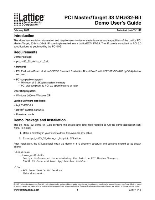
This document contains information and requirements to demonstrate features and capabilities of the Lattice <strong>PCI</strong><br />
<strong>Master</strong>/<strong>Target</strong>, <strong>33</strong> <strong>MHz</strong>/<strong>32</strong>-bit IP core implemented into a LatticeEC FPGA. The IP core is compliant to <strong>PCI</strong> 3.0<br />
specifications as published by the <strong>PCI</strong>-SIG.<br />
Requirements<br />
<strong>Demo</strong> Package:<br />
• pci_mt<strong>33</strong>_<strong>32</strong>_demo_v1_0.zip<br />
Hardware:<br />
• <strong>PCI</strong> Evaluation Board - LatticeECP/EC Standard Evaluation Board Rev B with LEFC6E -5F484C (fpBGA) device<br />
on board<br />
• PC-compatible systems:<br />
– Minimum of 512Kbytes system memory<br />
– <strong>PCI</strong> slot compliant to <strong>PCI</strong> 2.2 specifications or later<br />
Operating System:<br />
• Windows 2000 or Windows XP<br />
Lattice Software and Tools:<br />
®<br />
• ispLEVER 6.1<br />
® • ispVM System software<br />
• Download cable<br />
<strong>Demo</strong> Package and Installation<br />
The pci_mt<strong>33</strong>_<strong>32</strong>_demo_v1_0.zip contains the drivers and other files required to run the demo application software.<br />
To install:<br />
1. Make a directory in your favorite drive. For example, C:\Lattice<br />
2. Extract pci_mt<strong>33</strong>_<strong>32</strong>_demo_v1_0.zip into C:\Lattice<br />
After installation, the C:\Lattice\pci_mt<strong>33</strong>_<strong>32</strong>_demo_v_1_0 directory structure and contents should be as shown<br />
below:<br />
. \<strong>Bit</strong>stream<br />
| <br />
Design implementation containing the Lattice <strong>PCI</strong> <strong>Master</strong>/<strong>Target</strong>,<br />
<strong>33</strong>/<strong>32</strong> IP Core and <strong>Demo</strong> Application Module.<br />
.\Doc<br />
| <br />
This document.<br />
© 2007 Lattice Semiconductor Corp. All Lattice trademarks, registered trademarks, patents, and disclaimers are as listed at www.latticesemi.com/legal. All other brand<br />
or product names are trademarks or registered trademarks of their respective holders. The specifications and information herein are subject to change without notice.<br />
www.latticesemi.com<br />
<strong>PCI</strong> <strong>Master</strong>/<strong>Target</strong> <strong>33</strong> <strong>MHz</strong>/<strong>32</strong>-<strong>Bit</strong><br />
<strong>Demo</strong> User’s <strong>Guide</strong><br />
1<br />
tn1147_01.0
<strong>PCI</strong> <strong>Master</strong>/<strong>Target</strong> <strong>33</strong> <strong>MHz</strong>/<strong>32</strong>-<strong>Bit</strong><br />
Lattice Semiconductor <strong>Demo</strong> User’s <strong>Guide</strong><br />
.\Driver<br />
|-- <br />
|-- \2000<br />
|-- <br />
|-- \XP<br />
|--<br />
. \GUITest<br />
|--<br />
|--<br />
|--<br />
.\SDK<br />
|--<br />
|--<br />
The software consists of three parts: drivers, SDK and a GUI Test tool. The individual files are listed below:<br />
Driver Files:<br />
• Driver install file <br />
• Driver image file <br />
SDK Files:<br />
• SDK header file <br />
• SDK library file <br />
GUI Test Tool:<br />
• Executable file <br />
How to Install the Lattice <strong>PCI</strong> Device<br />
In order to run the demo, installation of the Lattice <strong>PCI</strong> device is required. In the Windows OS context the Lattice<br />
<strong>PCI</strong> device is composed of the <strong>PCI</strong> Evaluation Board and the device driver.<br />
The following installation sequence is based on a PC running on the Windows XP Operating System.<br />
Installation Procedure:<br />
1. With the PC power turned off, plug in the LatticeEC Standard Board into an empty <strong>PCI</strong> slot.<br />
2. Apply power to the PC and let the system boot-up.<br />
3. Open Device Manager and locate <strong>PCI</strong> standard RAM Controller,<br />
as shown in figure 1. The <strong>PCI</strong> Evaluation<br />
Board is detected as <strong>PCI</strong> standard RAM Controller in Windows Device Manager.<br />
Note: Depending on the PC system, there could be multiple <strong>PCI</strong> standard RAM Controllers shown under<br />
the Device Manager. There are two ways to properly identify and select the Lattice <strong>PCI</strong> Evaluation Board<br />
the first time. In Figure 1, the last <strong>PCI</strong> standard RAM Controller in the list corresponds to the Lattice <strong>PCI</strong><br />
Evaluation Board.<br />
a. Vendor ID: The Lattice Vendor ID used in this demo package is 1573(h). Therefore, the selected<br />
<strong>PCI</strong> standard RAM Controller Vendor ID must be 1573.<br />
2
<strong>PCI</strong> <strong>Master</strong>/<strong>Target</strong> <strong>33</strong> <strong>MHz</strong>/<strong>32</strong>-<strong>Bit</strong><br />
Lattice Semiconductor <strong>Demo</strong> User’s <strong>Guide</strong><br />
b.<br />
Location: A <strong>PCI</strong> Add-in card, such as the Lattice <strong>PCI</strong> Evaluation board, is assigned a location. For<br />
example:<br />
Location: <strong>PCI</strong> bus 2, device 12, function 0<br />
Figure 1. Windows XP OS Device Manager<br />
4. Select <strong>PCI</strong> standard RAM Controller and select<br />
Figure 2.<br />
Figure 2. Update Driver<br />
3<br />
Update Driver... from the pop-up menu, as shown in
<strong>PCI</strong> <strong>Master</strong>/<strong>Target</strong> <strong>33</strong> <strong>MHz</strong>/<strong>32</strong>-<strong>Bit</strong><br />
Lattice Semiconductor <strong>Demo</strong> User’s <strong>Guide</strong><br />
5. Select<br />
Select<br />
Install from a list or specific location (Advanced) , as shown in Figure 3.<br />
Next.<br />
Figure 3. Driver Installation Option<br />
6. Select Don’t search. I will choose the driver to install as shown in Figure 4.<br />
Select<br />
Next.<br />
Figure 4. Choose Driver to Install<br />
4
<strong>PCI</strong> <strong>Master</strong>/<strong>Target</strong> <strong>33</strong> <strong>MHz</strong>/<strong>32</strong>-<strong>Bit</strong><br />
Lattice Semiconductor <strong>Demo</strong> User’s <strong>Guide</strong><br />
7. The Install From Disk dialog box appears, as shown in Figure 5.<br />
Figure 5. Install from Disk<br />
8. Select Browse,<br />
and then select the file<br />
directory as shown in Figure 6.<br />
Select<br />
Open.<br />
Figure 6. Locate File pcicore.inf<br />
9. Choose Lattice <strong>PCI</strong>Core Device and select<br />
pcicore.inf,<br />
located in C:\Lattice\pci_mt<strong>33</strong>_<strong>32</strong>_demo_v1_0<br />
Next,<br />
as shown in Figure 7.<br />
5
<strong>PCI</strong> <strong>Master</strong>/<strong>Target</strong> <strong>33</strong> <strong>MHz</strong>/<strong>32</strong>-<strong>Bit</strong><br />
Lattice Semiconductor <strong>Demo</strong> User’s <strong>Guide</strong><br />
Figure 7. Select the Lattice <strong>PCI</strong> Device<br />
10.In the Files Needed dialog box, select Browse and locate the file pcicore.sys in the directory<br />
C:\Lattice\pci_mt<strong>33</strong>_<strong>32</strong>_demo_v1_0 as shown in Figure 8.<br />
Figure 8. Files Needed/Locate File pcicore.sys<br />
6
<strong>PCI</strong> <strong>Master</strong>/<strong>Target</strong> <strong>33</strong> <strong>MHz</strong>/<strong>32</strong>-<strong>Bit</strong><br />
Lattice Semiconductor <strong>Demo</strong> User’s <strong>Guide</strong><br />
11.In the Locate File window, select the pcicore.sys file and<br />
12.Select OK in the Files Needed and Install from Disk dialog boxes.<br />
7<br />
Open,<br />
as shown in Figure 9.<br />
13.The Hardware Update Wizard copies the driver file into the system and completes the driver installation, as<br />
shown in Figure 9.<br />
Figure 9. Hardware Update Wizard Completed<br />
14. Lattice <strong>PCI</strong>Core Device appears in the System devices list, showing successful installation.<br />
Figure 10. The Lattice <strong>PCI</strong> Device in the Systems Devices List
<strong>PCI</strong> <strong>Master</strong>/<strong>Target</strong> <strong>33</strong> <strong>MHz</strong>/<strong>32</strong>-<strong>Bit</strong><br />
Lattice Semiconductor <strong>Demo</strong> User’s <strong>Guide</strong><br />
Running the <strong>Demo</strong><br />
After successful installation of the <strong>PCI</strong> Evaluation Board and the device driver, select/open the application file<br />
GUITest.exe located in the C:\Lattice\pci_mt<strong>33</strong>_<strong>32</strong>_demo_v_1_0\GUITest directory.<br />
The main GUI for running the demo is shown in Figure 11.<br />
Figure 11. Main GUI for <strong>PCI</strong> <strong>Demo</strong><br />
Then, follow this sequence:<br />
1. Select Scan Lattice Device.<br />
This verifies the presence of the Lattice <strong>PCI</strong> Evaluation Board as a valid system<br />
device. Notice the number of devices, BARs and their properties.<br />
2. Select<br />
Select Lattice Device.<br />
Figure 12. Select Lattice Device<br />
Select<br />
OK.<br />
8
<strong>PCI</strong> <strong>Master</strong>/<strong>Target</strong> <strong>33</strong> <strong>MHz</strong>/<strong>32</strong>-<strong>Bit</strong><br />
Lattice Semiconductor <strong>Demo</strong> User’s <strong>Guide</strong><br />
3. Select<br />
<strong>Demo</strong> Registers.<br />
Figure 13. <strong>Demo</strong> Registers<br />
a. Select Load Register Init Values from File.<br />
Interrupt and DMA registers must be set prior to testing<br />
these functions. A pop-up window will bring up a file to set initial register values.<br />
Figure 14. Loading Reg.map File<br />
b. Select the Reg.map file.<br />
c. Select<br />
d. Select<br />
Open.<br />
Init.<br />
This loads the initial values to all the demo registers.<br />
9
<strong>PCI</strong> <strong>Master</strong>/<strong>Target</strong> <strong>33</strong> <strong>MHz</strong>/<strong>32</strong>-<strong>Bit</strong><br />
Lattice Semiconductor <strong>Demo</strong> User’s <strong>Guide</strong><br />
4. Select Function Test.<br />
The Function Test GUI is shown below. To support the corresponding demo functions,<br />
the GUI is divided into the following sections:<br />
• Configuration Space:<br />
Read/Write access to the Lattice <strong>PCI</strong> Device CSR<br />
• I/O or Memory Space:<br />
I/O or Memory Space single Read/Write transaction<br />
•DMA:<br />
DMA Read/Write Transfers from/to PC system memory. Lattice <strong>PCI</strong> Device stores data read<br />
from system memory.<br />
• Data:<br />
Select and Generate the Data Pattern for DMA transfer<br />
• Block Write/Read:<br />
Supports file transfer to/from disk drive<br />
• Interrupt: Software generated interrupt<br />
Figure 15. Function Test GUI<br />
a.<br />
Configuration Space:<br />
Read/Write <strong>PCI</strong> Configuration Space Registers (CSR)<br />
Select<br />
Scan Configuration Space.<br />
Examine contents of Results Window, Vendor ID, etc.<br />
10
<strong>PCI</strong> <strong>Master</strong>/<strong>Target</strong> <strong>33</strong> <strong>MHz</strong>/<strong>32</strong>-<strong>Bit</strong><br />
Lattice Semiconductor <strong>Demo</strong> User’s <strong>Guide</strong><br />
Figure 16. Scanning Lattice <strong>PCI</strong> Device CSR<br />
b.<br />
Enter the following:<br />
Offset (hex): 00000004<br />
<strong>Bit</strong>s Width: <strong>32</strong> bits<br />
Data (hex): 0000075f<br />
Select Write.<br />
The <strong>PCI</strong> Command register contents are updated.<br />
Select<br />
Read.<br />
Read/verify the contents of the <strong>PCI</strong> Command register.<br />
I/O or Memory Space:<br />
Read/write to I/O or memory space.<br />
11
<strong>PCI</strong> <strong>Master</strong>/<strong>Target</strong> <strong>33</strong> <strong>MHz</strong>/<strong>32</strong>-<strong>Bit</strong><br />
Lattice Semiconductor <strong>Demo</strong> User’s <strong>Guide</strong><br />
Figure 17. I/O Space - Single R/W Transaction<br />
I/O Space:<br />
Single read/write transaction (refer to Figure 17).<br />
Read - Enter the following:<br />
BAR (dec): 1<br />
Offset (hex): 00000048<br />
<strong>Bit</strong>s Width: <strong>32</strong> bits<br />
Data (hex):<br />
Select<br />
Read.<br />
Examine result. Should be all 0’s<br />
Write - Enter the following.<br />
BAR (dec): 1<br />
Offset (hex): 00000048<br />
<strong>Bit</strong>s Width: 08 bits<br />
Data (hex): FFFFFFBD<br />
Select Write. This executes the write.<br />
Read/Verify - Select Read.<br />
BAR (dec): 1<br />
Offset (hex): 00000048<br />
<strong>Bit</strong>s Width: 08 bits<br />
Data (hex): 000000BD<br />
Question: Why is the data read back as 000000BD(h)?<br />
12
<strong>PCI</strong> <strong>Master</strong>/<strong>Target</strong> <strong>33</strong> <strong>MHz</strong>/<strong>32</strong>-<strong>Bit</strong><br />
Lattice Semiconductor <strong>Demo</strong> User’s <strong>Guide</strong><br />
Memory Space: Single read/write transaction.<br />
Figure 18. Memory Space - Single R/W Transaction<br />
Read - Enter the following:<br />
BAR (dec): 0<br />
Offset (hex): 00000074<br />
<strong>Bit</strong>s width: <strong>32</strong> bits<br />
Data (hex):<br />
Select Read. Examine result. Should be all 0’s.<br />
Write - Enter the following:<br />
BAR (dec): 0<br />
Offset (hex): 00000074<br />
<strong>Bit</strong>s width: <strong>32</strong> bits<br />
Data (hex): 98C5B7D3 (or other <strong>32</strong>-bit data)<br />
Select Write. This executes the write.<br />
Read/Verify - Select Read.<br />
Verify data read back.<br />
BAR (dec): 0<br />
Offset (hex): 00000074<br />
<strong>Bit</strong>s Width: <strong>32</strong> bits<br />
Data (hex):<br />
13
<strong>PCI</strong> <strong>Master</strong>/<strong>Target</strong> <strong>33</strong> <strong>MHz</strong>/<strong>32</strong>-<strong>Bit</strong><br />
Lattice Semiconductor <strong>Demo</strong> User’s <strong>Guide</strong><br />
c. DMA Write/Read<br />
Try reading with different <strong>Bit</strong>s Width setting.<br />
Select Exit to go to main GUI<br />
As described above, Select <strong>Demo</strong> Registers, re-load Reg.map file and Exit.<br />
Note: If any of the <strong>Demo</strong> Registers are modified before starting the DMA transfer test, the<br />
<strong>Demo</strong> Registers must be reinitialized, otherwise the application software will no longer function.<br />
Select Function Test.<br />
Figure 19. Random Data Pattern for DMA Transfer<br />
Select Set DMA Data >Random>Generate Pattern and close the window.<br />
To specify size of data to be transferred, enter the following in the DMA section:<br />
Length (hex): 00000050<br />
Select DMA Write. This writes data, with Length: 50(hex), to system memory.<br />
Select DMA Read. This reads data from the system memory and stores it in the BAR0 memory<br />
space (EBRs in the LatticeEC6 device). The result is shown in Figure 20.<br />
14
<strong>PCI</strong> <strong>Master</strong>/<strong>Target</strong> <strong>33</strong> <strong>MHz</strong>/<strong>32</strong>-<strong>Bit</strong><br />
Lattice Semiconductor <strong>Demo</strong> User’s <strong>Guide</strong><br />
Figure 20. Result after DMA Read<br />
Verify data in BAR0 memory space.<br />
In I/O or Memory Space, enter/select:<br />
BAR (dec): 0<br />
Offset (hex): 00000000<br />
<strong>Bit</strong>s Width: <strong>32</strong> bits<br />
Data:<br />
Select Read and note the data readback. Compare the data with the Random Data Pattern<br />
starting at Offset 00000000(h). The two should match.<br />
d. Block Write/Read. A segment of a “data” file is read from the <strong>PCI</strong> <strong>Demo</strong> package installation directory<br />
and written to the BAR0 memory space. The contents of the BAR0 memory space are modified<br />
and then saved, with a different filename, in the same directory as the original “data” file.<br />
Read the “data” file and write into BAR0 memory (EBR in LatticeEC6).<br />
15
<strong>PCI</strong> <strong>Master</strong>/<strong>Target</strong> <strong>33</strong> <strong>MHz</strong>/<strong>32</strong>-<strong>Bit</strong><br />
Lattice Semiconductor <strong>Demo</strong> User’s <strong>Guide</strong><br />
Figure 21. Locating and Opening block.dat File<br />
In Block Write/Read section:<br />
Go to Read file:>Browse to locate the file block.dat in the following directory:<br />
C:\Lattice\pci_mt<strong>33</strong>_<strong>32</strong>_demo_v_1_0\GUITest<br />
To set segment size, enter the following:<br />
Length (hex): 00000070<br />
Select Block Write. This writes the file segment into the LatticeEC6 EBR.<br />
Verify the data written into the EBR and modify the data in location 0x0.<br />
In I/O or Memory Space section, enter the following:<br />
BAR (dec): 0<br />
Offset (hex): 00000000<br />
<strong>Bit</strong>s Width: <strong>32</strong> bits<br />
Data (hex):<br />
Note: Offset value can be within the range Length (hex): 00000070.<br />
Select Read.<br />
Modify the data by entering the following:<br />
Data (hex): “Different <strong>32</strong>-bit data”<br />
16
<strong>PCI</strong> <strong>Master</strong>/<strong>Target</strong> <strong>33</strong> <strong>MHz</strong>/<strong>32</strong>-<strong>Bit</strong><br />
Lattice Semiconductor <strong>Demo</strong> User’s <strong>Guide</strong><br />
Select Write to change the contents of BAR0, Memory address 0x0.<br />
Select Read to verify the data changed.<br />
Read the contents of the EBR and save it as a file. In Block Write/Read Section:<br />
Select Write->Browse and find the directory called<br />
C:\Lattice\pci_mt<strong>33</strong>_<strong>32</strong>_demo_v_1_0\GUITest.<br />
In the Save As window enter as the file name: block_mod.dat.<br />
Select Save.<br />
Select Block Read. This saves the contents of the EBR as a file named<br />
block_mod.dat.<br />
Compare the original data file and the modified data file.<br />
Select View under Read file. This displays the original data file block.dat.<br />
Select View under Write file. This displays the modified data file block_mod.dat.<br />
Compare the contents of the two files from offset 00(hex) to 03(hex). The result should<br />
look like Figure 22.<br />
Figure 22. Compare Original and Modified/Saved Data File<br />
17
<strong>PCI</strong> <strong>Master</strong>/<strong>Target</strong> <strong>33</strong> <strong>MHz</strong>/<strong>32</strong>-<strong>Bit</strong><br />
Lattice Semiconductor <strong>Demo</strong> User’s <strong>Guide</strong><br />
e. Interrupt. In this demo, an interrupt is initiated by the software. This is accomplished by selecting<br />
Generate the Interrupt in the Function Test GUI. The Lattice <strong>PCI</strong> device drives the physical INTx<br />
line to logic low. Software also acknowledges the interrupt. This transaction is shown in Figure 23.<br />
Figure 23. Software Initiated/Acknowledged Interrupt<br />
18
<strong>PCI</strong> <strong>Master</strong>/<strong>Target</strong> <strong>33</strong> <strong>MHz</strong>/<strong>32</strong>-<strong>Bit</strong><br />
Lattice Semiconductor <strong>Demo</strong> User’s <strong>Guide</strong><br />
<strong>Demo</strong> Logic Functions<br />
Figure 24 shows the Lattice <strong>PCI</strong> Device <strong>Demo</strong> Logic block diagram. The <strong>Demo</strong> Logic is composed of logic functions<br />
supporting the <strong>PCI</strong> <strong>Master</strong>/<strong>Target</strong> IP core. For further information on these functions, please refer to the <strong>PCI</strong><br />
Core User’s <strong>Guide</strong> on the Lattice website at www.latticesemi.com.<br />
Figure 24. <strong>PCI</strong> <strong>Master</strong>/<strong>Target</strong> IP Core + <strong>Demo</strong> Logic Block Diagram<br />
LatticeECP6 FPGA<br />
FIFO<br />
Control<br />
FIFO<br />
(EBR)<br />
Read Data<br />
Registers<br />
<strong>Master</strong><br />
Function<br />
Data Generator<br />
Registers<br />
<strong>Target</strong><br />
Function<br />
<strong>PCI</strong> <strong>Master</strong>/<strong>Target</strong> <strong>33</strong> <strong>MHz</strong>/<strong>32</strong>-bit IP Core BARs<br />
The three Base Address Registers implemented in the <strong>PCI</strong> <strong>Master</strong>/<strong>Target</strong> IP Core are described in Table 1.<br />
Table 1. <strong>PCI</strong> <strong>Master</strong>/<strong>Target</strong> IP Core BARs<br />
Write Data<br />
BAR Memory / I/O Space Size Access Description<br />
0 Memory 0x4000 R/W<br />
Represented as <strong>32</strong>-bit wide FIFO in Figure 24. Physically, the FIFO<br />
is implemented as EBRs in the LatticeEC6 FPGA. Data is stored in<br />
the FIFO during DMA transfer. Each location is also read/write<br />
accessible via the Test Function GUI.<br />
1 I/O 0xFF R/W General-purpose I/O.<br />
2 I/O 0xFF R/W<br />
Top<br />
Control<br />
<strong>Demo</strong> Registers. Implements the registers to support interrupt and<br />
DMA functions.<br />
19<br />
Local<br />
Bus<br />
CSR<br />
Lattice<br />
<strong>PCI</strong><br />
<strong>Master</strong>/<br />
<strong>Target</strong><br />
IP Core<br />
<strong>PCI</strong> Bus<br />
<strong>33</strong><strong>MHz</strong>/<br />
<strong>32</strong> <strong>Bit</strong>s
<strong>PCI</strong> <strong>Master</strong>/<strong>Target</strong> <strong>33</strong> <strong>MHz</strong>/<strong>32</strong>-<strong>Bit</strong><br />
Lattice Semiconductor <strong>Demo</strong> User’s <strong>Guide</strong><br />
<strong>Demo</strong> Registers Description<br />
The <strong>Demo</strong> Registers and supporting hardware/logic modules are used by the driver/software to run the demo<br />
applications.<br />
Table 2. <strong>Demo</strong> Registers<br />
BAR Offset Name Access <strong>Bit</strong>s Description<br />
2 0x0<br />
2 0x4<br />
2 0x8<br />
2 0x10<br />
2 0x14<br />
2 0x18<br />
2 0x1C<br />
Interrupt Generation and Status<br />
Interrupts can be masked or un-masked. The Interrupt Mask Register controls this function as described in Table 2.<br />
If un-masked, there are two ways an interrupt is initiated:<br />
1. By software<br />
Interrupt Control<br />
Register<br />
Interrupt Status<br />
Register<br />
Interrupt Mask<br />
Register<br />
DMA Control<br />
Register<br />
DMA Status<br />
Register<br />
DMA Address<br />
Register<br />
DMA Length<br />
Register<br />
2. End of DMA transfer<br />
R/W<br />
R<br />
R/W<br />
R/W<br />
[0]<br />
When 0, the demo logic will generate the interrupt. When 1, the<br />
demo logic will clear the interrupt.<br />
[1] When 1, the demo logic will clear the DMA interrupt<br />
[31:2] Reserved<br />
[0]<br />
Software-initiated interrupt<br />
1: Interrupt Generated<br />
0: None<br />
DMA-generated interrupt<br />
[1] 1: Interrupt Generated<br />
0: None<br />
[31:2] Reserved<br />
[0]<br />
R [31:0]<br />
1: Mask the software interrupt. Software-initiated interrupt.is not<br />
recognized.<br />
0: None<br />
1: Mask the DMA interrupt. Interrupt generated during DMA trans-<br />
[1] fers is not recognized.<br />
0: None<br />
[31:2] Reserved<br />
[0] 1: Starts the DMA transfer.<br />
[1]<br />
1: DMA read mode<br />
0: DMA write mode.<br />
[31:2] Reserved<br />
This register contains the status bits of the DMA process.<br />
<strong>Bit</strong> [0] = 1. DMA transfer is in progress.<br />
<strong>Bit</strong> [1] = 1. Indicates there is an error in the DMA process.<br />
R/W [31:0] This register contains the starting address for the DMA transfer.<br />
R/W [31:0]<br />
2 0x20 Reserved [31:0] Reserved for future use.<br />
The data length for the DMA transfer. Currently limited to maximum<br />
of 0x100(hex).<br />
The software method is used to verify the interrupt function and simulate the hardware to generate the interrupt.<br />
When the software sets bit [0] of the Interrupt Control Register (BAR2/Offset 0) 0, the <strong>Demo</strong> Logic will generate the<br />
hardware interrupt. The interrupt is cleared when the software writes a 1 to this same bit location. The status for<br />
software-initiated interrupt is indicated via the Interrupt Status Register, bit[0] as described in Table 2.<br />
When the DMA transfer is completed, an interrupt is also generated. In this case it is purely hardware. This interrupt<br />
is cleared when the bit [1] of the Interrupt Control Register is set to 1.<br />
20
<strong>PCI</strong> <strong>Master</strong>/<strong>Target</strong> <strong>33</strong> <strong>MHz</strong>/<strong>32</strong>-<strong>Bit</strong><br />
Lattice Semiconductor <strong>Demo</strong> User’s <strong>Guide</strong><br />
DMA Transfers<br />
The following registers must be initialized with the appropriate values.<br />
• DMA Address Register<br />
• DMA Length Register<br />
• DMA Direction Register<br />
• DMA Control Register<br />
The DMA Control Register should be the last one accessed and the only to start the DMA transfer.<br />
If the demo logic is used, the registers’ configuration can be completed by loading the default file Reg.map.<br />
Reg.map File<br />
The Reg.map file contains the initial <strong>Demo</strong> Register values to execute the DMA transfer successfully when running<br />
the demo via the GUI Test applications software.<br />
The Register Config File (Reg.map):<br />
Lattice<br />
;Lattice <strong>PCI</strong>CORE Test Tool Register Map File<br />
;<br />
; Register Width<br />
; (B)yte --- 8 bits<br />
; (W)ord --- 16 bits<br />
; (D)word --- <strong>32</strong> bits<br />
;<br />
; Access Method<br />
; R --- Read Only<br />
; W --- Write Only<br />
; A --- Read and Write<br />
;Interrupt Status Register<br />
Reg:0 Bar=2,Offset=0x4,RegWidth=D,<strong>Bit</strong>Start=0,<strong>Bit</strong>Width=<strong>32</strong>,Access=R<br />
;Interrupt Acknowledge Register<br />
Reg:1 Bar=2,Offset=0x0,RegWidth=D,<strong>Bit</strong>Start=0,<strong>Bit</strong>Width=<strong>32</strong>,Access=W<br />
;Interrupt Mask Register<br />
Reg:2 Bar=2,Offset=0x8,RegWidth=D,<strong>Bit</strong>Start=0,<strong>Bit</strong>Width=<strong>32</strong>,Access=A<br />
;DMA Address Register<br />
Reg:3 Bar=2,Offset=0x18,RegWidth=D,<strong>Bit</strong>Start=0,<strong>Bit</strong>Width=<strong>32</strong>,Access=A<br />
;DMA Length Register<br />
Reg:4 Bar=2,Offset=0x1c,RegWidth=D,<strong>Bit</strong>Start=0,<strong>Bit</strong>Width=<strong>32</strong>,Access=A<br />
;DMA Direction Register<br />
Reg:5 Bar=2,Offset=0x10,RegWidth=D,<strong>Bit</strong>Start=1,<strong>Bit</strong>Width=1,Access=A<br />
;DMA Control Register<br />
Reg:6 Bar=2,Offset=0x10,RegWidth=D,<strong>Bit</strong>Start=0,<strong>Bit</strong>Width=1,Access=A<br />
;DMA Status Register<br />
Reg:7 Bar=2,Offset=0x4,RegWidth=D,<strong>Bit</strong>Start=1,<strong>Bit</strong>Width=1,Access=R<br />
21
<strong>PCI</strong> <strong>Master</strong>/<strong>Target</strong> <strong>33</strong> <strong>MHz</strong>/<strong>32</strong>-<strong>Bit</strong><br />
Lattice Semiconductor <strong>Demo</strong> User’s <strong>Guide</strong><br />
How to Use SDK<br />
1. Initialize the device. Before the device can be initialized, the EnumDevice( ) function must be invoked to<br />
determine how many devices exist in the system. You can initialize the device by invoking the function Init-<br />
Device( ).<br />
2. Access the Configuration Space. Below are the functions that have access to the configuration space.<br />
ReadConfigB( ) Read a byte from the configuration space.<br />
ReadConfigW( ) Read a word from the configuration space.<br />
ReadConfigD( ) Read a double word from the configuration space.<br />
ReadDataFromConfig( ) Read a data buffer from the configuration space.<br />
WriteConfigB( ) Write a byte to the configuration space.<br />
WriteConfigW ( ) Write a word to the configuration space.<br />
WriteConfigD( ) Write a double word to the configuration space.<br />
WriteDataToConfig( ) Write a data buffer to the configuration space.<br />
Note: Before you can make the above function calls, you must initialize the device by invoking the InitDevice(<br />
) function.<br />
3. Access the I/O Space or Memory Space. Below are the functions that have access to the I/O space or<br />
memory space.<br />
ReadBarB( ) Read a byte from the I/O space or memory space.<br />
ReadBarW( ) Read a word from the I/O space or memory space.<br />
ReadBarD( ) Read a double word from the I/O space or memory space.<br />
ReadDataFromBar( ) Read a data buffer from the I/O space or memory space.<br />
WriteBarB( ) Write a byte to the I/O space or memory space.<br />
WriteBarW( ) Write a word to the I/O space or memory space.<br />
WriteBarD( ) Write a double word to the I/O space or memory space.<br />
WriteDataToBar( ) Write a data buffer to the I/O space or memory space.<br />
Note: Before you can make the above function calls, you must initialize the device by invoking the InitDevice(<br />
) function.<br />
4. Process the Interrupt. You can install the ISR (interrupt service routine) by invoking the RegISRForApp( )<br />
function. The ISR prototype reads:<br />
void AppISR(void *data)<br />
Before the ISR can be installed, the interrupt registers must be set. The following functions can be used to<br />
set the registers:<br />
SetIntrStatusReg( ) Set the interrupt status register to identify whether the interrupt generates.<br />
SetIntrMaskReg( ) Set the interrupt mask register to disable or enable interrupt.<br />
SetIntrAckReg( ) Set the interrupt acknowledge register to clear the interrupt.<br />
5. DMA Operation. The DoDMA( ) function is used for DMA operation. When the DMA operation completes,<br />
the device generates an interrupt message. Therefore, the function DMADone( ) must be invoked in the<br />
ISR. Otherwise, the function DoDMA( ) will be blocked. Before DMA operation, DMA registers must be set.<br />
The following functions can be used to set the registers:<br />
SetDmaAddrReg( ) Set the DMA address register.<br />
SetDmaLenReg( ) Set the DMA length register.<br />
SetDmaDirectionReg( ) Set the DMA direction register.<br />
22
<strong>PCI</strong> <strong>Master</strong>/<strong>Target</strong> <strong>33</strong> <strong>MHz</strong>/<strong>32</strong>-<strong>Bit</strong><br />
Lattice Semiconductor <strong>Demo</strong> User’s <strong>Guide</strong><br />
SetDmaCtrlReg( ) Set the DMA control register.<br />
SetDmaStatusReg( ) Set the DMA status register.<br />
Note: For the register map, see the <strong>Demo</strong> Registers Description section of this document.<br />
Design Example<br />
#include “pcicore.h”<br />
void AppIsr(void *data)<br />
{<br />
unsigned long value, status;<br />
ReadBarD(0, 2, 4, &status);<br />
}<br />
if(status)<br />
{<br />
value = 3;<br />
WriteBarD(0, 2, 0, &value);<br />
}<br />
if(status & 0x2)<br />
DMADone();<br />
int main(int argc, char* argv[])<br />
{<br />
unsigned long devnum, I, value;<br />
unsigned char buf[256];<br />
devnum = EnumDevice();<br />
if(devnum == 0)<br />
{<br />
printf(“Device can not be found\n”);<br />
return 1;<br />
}<br />
InitDevice(0);<br />
// Access the configuration space<br />
ReadDataFromConfig(0, 0, buf, 256);<br />
for(i = 0; i < 256; i++)<br />
{<br />
printf(“0x%02x “, *(buf + i));<br />
if(!((i + 1) % 4))<br />
printf(“\n”);<br />
}<br />
for(i = 0; i < 256; i++)<br />
*(buf + i) = (unsigned char)i;<br />
// Access the I/O or memory space<br />
WriteDataToBar(0, 0, 0, buf, 256);<br />
ReadDataFromBar(0, 0, 0, buf, 256);<br />
23
<strong>PCI</strong> <strong>Master</strong>/<strong>Target</strong> <strong>33</strong> <strong>MHz</strong>/<strong>32</strong>-<strong>Bit</strong><br />
Lattice Semiconductor <strong>Demo</strong> User’s <strong>Guide</strong><br />
for(i = 0; i < 256; i++)<br />
{<br />
printf(“0x%02x “, *(buf + i));<br />
if(!((i + 1) % 8))<br />
printf(“\n”);<br />
}<br />
// Config the register<br />
SetIntrAckReg (0, 2, 0x00, REG_WIDTH_<strong>32</strong>, REG_WRITE_ONLY, <strong>32</strong>, 0);<br />
SetIntrStatusReg (0, 2, 0x04, REG_WIDTH_<strong>32</strong>, REG_WRITE_READ, <strong>32</strong>, 0);<br />
SetIntrMaskReg (0, 2, 0x08, REG_WIDTH_<strong>32</strong>, REG_WRITE_READ, <strong>32</strong>, 0);<br />
SetDmaCtrlReg (0, 2, 0x10, REG_WIDTH_<strong>32</strong>, REG_WRITE_READ, 1, 0);<br />
SetDmaDirectionReg (0, 2, 0x10, REG_WIDTH_<strong>32</strong>, REG_WRITE_READ, 1, 1);<br />
SetDmaAddrReg (0, 2, 0x18, REG_WIDTH_<strong>32</strong>, REG_WRITE_READ, <strong>32</strong>, 0);<br />
SetDmaLenReg (0, 2, 0x1C, REG_WIDTH_<strong>32</strong>, REG_WRITE_READ, <strong>32</strong>, 0);<br />
SetDmaStatusReg (0, 2, 0x14, REG_WIDTH_<strong>32</strong>, REG_WRITE_READ, <strong>32</strong>, 0);<br />
RegISRForApp(0, AppIsr, NULL);<br />
// Generate the software interrupt<br />
value = 2;<br />
WriteBarD(0, 2, 0, &value);<br />
// DMA operation<br />
for(i = 0; i < 256; i++)<br />
*(buf + i) = 0xFF - (unsigned char)i;<br />
DoDMA(0, buf, 256, DMA_WRITE);<br />
DoDMA(0, buf, 256, DMA_READ);<br />
for(i = 0; i < 256; i++)<br />
{<br />
printf(“0x%02x “, *(buf + i));<br />
if(!((i + 1) % 8))<br />
printf(“\n”);<br />
}<br />
UnregISRForApp(0);<br />
UninitDevice(0);<br />
}<br />
Technical Support Assistance<br />
Hotline: 1-800-LATTICE (North America)<br />
+1-503-268-8001 (Outside North America)<br />
e-mail: techsupport@latticesemi.com<br />
Internet: www.latticesemi.com<br />
24
<strong>PCI</strong> <strong>Master</strong>/<strong>Target</strong> <strong>33</strong> <strong>MHz</strong>/<strong>32</strong>-<strong>Bit</strong><br />
Lattice Semiconductor <strong>Demo</strong> User’s <strong>Guide</strong><br />
Revision History<br />
Date Version Change Summary<br />
February 2007 01.0 Initial release.<br />
25