EB65 - ispMACH 4256ZE Breakout Board Evaluation Kit User's Guide
EB65 - ispMACH 4256ZE Breakout Board Evaluation Kit User's Guide
EB65 - ispMACH 4256ZE Breakout Board Evaluation Kit User's Guide

Create successful ePaper yourself
Turn your PDF publications into a flip-book with our unique Google optimized e-Paper software.
�<br />
<strong>ispMACH</strong> <strong>4256ZE</strong> <strong>Breakout</strong> <strong>Board</strong> <strong>Evaluation</strong> <strong>Kit</strong><br />
�<br />
User’s <strong>Guide</strong><br />
March 2012<br />
Revision: <strong>EB65</strong>_01.1
Introduction<br />
2<br />
<strong>ispMACH</strong> <strong>4256ZE</strong> <strong>Breakout</strong> <strong>Board</strong><br />
<strong>Evaluation</strong> <strong>Kit</strong> User’s <strong>Guide</strong><br />
Thank you for choosing the Lattice Semiconductor <strong>ispMACH</strong> ® <strong>4256ZE</strong> <strong>Breakout</strong> <strong>Board</strong> <strong>Evaluation</strong> <strong>Kit</strong>!<br />
This user’s guide describes how to start using the <strong>ispMACH</strong> <strong>4256ZE</strong> <strong>Breakout</strong> <strong>Board</strong>, an easy-to-use platform for<br />
evaluating and designing with the <strong>ispMACH</strong> <strong>4256ZE</strong> CPLD. Along with the board and accessories, this kit includes<br />
a pre-loaded hardware test program. You may also reprogram the on-board <strong>ispMACH</strong> <strong>4256ZE</strong> device to review<br />
your own custom designs.<br />
Note: Static electricity can severely shorten the lifespan of electronic components. See the Storage and Handling<br />
section for handling and storage tips.<br />
Features<br />
The <strong>ispMACH</strong> <strong>4256ZE</strong> <strong>Breakout</strong> <strong>Board</strong> <strong>Evaluation</strong> <strong>Kit</strong> includes:<br />
<strong>ispMACH</strong> 4000ZE <strong>Breakout</strong> <strong>Board</strong> – The board is a 3” x 3” form factor that features the following on-board<br />
components and circuits:<br />
– <strong>ispMACH</strong> <strong>4256ZE</strong> CPLD (LC<strong>4256ZE</strong>-5TN144C)<br />
– USB mini-B connector for power and programming<br />
– Eight LEDs<br />
– 4x15 prototype area<br />
– Four 2x20 expansion header landings for general I/O, JTAG, and external power<br />
– 1x8 expansion header landing for JTAG<br />
– 3.3V and 1.8V supply rails<br />
Pre-loaded Demo – The kit includes a pre-loaded counter design that highlights use of the embedded <strong>ispMACH</strong><br />
4000ZE oscillator and programmable I/Os configured for LED drive.<br />
USB Connector Cable – The board is powered from the USB mini-B socket when connected to a host PC. The<br />
USB channel also provides a programming interface to the <strong>ispMACH</strong> <strong>4256ZE</strong> JTAG port.<br />
Lattice <strong>Breakout</strong> <strong>Board</strong> <strong>Evaluation</strong> <strong>Kit</strong>s Web Page – Visit www.latticesemi.com/breakoutboards for the latest<br />
documentation (including this guide), demo designs, and drivers for the kit.<br />
The content of this user’s guide includes demo operation, programming instructions, top-level functional descriptions<br />
of the <strong>Breakout</strong> board, descriptions of the on-board connectors, and a complete set of schematics.
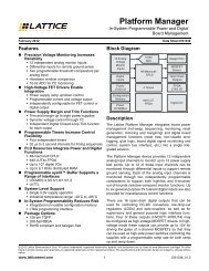
Figure 1. <strong>ispMACH</strong> <strong>4256ZE</strong> <strong>Breakout</strong> <strong>Board</strong>, Top Side<br />
Left Side<br />
Two 2x20 Header<br />
Landings (J3, J4)<br />
Storage and Handling<br />
LED Array 4x15 Prototype Area<br />
USB Interface<br />
(J2)<br />
3<br />
<strong>ispMACH</strong> <strong>4256ZE</strong> <strong>Breakout</strong> <strong>Board</strong><br />
<strong>Evaluation</strong> <strong>Kit</strong> User’s <strong>Guide</strong><br />
JTAG Header Landing<br />
(J1)<br />
Right Side<br />
Two 2x20 Header<br />
Landings (J5, J6)<br />
Static electricity can shorten the lifespan of electronic components. Please observe these tips to prevent damage<br />
that could occur from electro-static discharge:<br />
Use anti-static precautions such as operating on an anti-static mat and wearing an anti-static wrist-band.<br />
Store the evaluation board in the packaging provided.<br />
Touch a metal USB housing to equalize voltage potential between you and the board.<br />
Software Requirements<br />
You should install the following software before you begin developing new designs for the <strong>Breakout</strong> board:<br />
FTDI USB Hardware Drivers (www.latticesemi.com/breakoutboards) or ispVM System 17.9 (required for re-programming)<br />
Optional: ispLEVER Classic 1.4 (<strong>ispMACH</strong> 4000ZE CPLD support)<br />
Demonstration Design<br />
Lattice provides a pre-programmed demo to illustrate basic operation of the <strong>ispMACH</strong> <strong>4256ZE</strong> CPLD device. The<br />
design integrates an up-counter with the on-chip oscillator and timer (OSCTIMER) hardware feature. The design<br />
alternates to CPLD outputs, illuminating LEDs D1, D3, D5 and D7 then LEDs D2, D4, D6 and D8.<br />
Note: To restore the factory default demo or program it with other Lattice-supplied examples see the Download<br />
Demo Designs section of this document.
4<br />
<strong>ispMACH</strong> <strong>4256ZE</strong> <strong>Breakout</strong> <strong>Board</strong><br />
<strong>Evaluation</strong> <strong>Kit</strong> User’s <strong>Guide</strong><br />
The preprogrammed demonstration design is an up counter and an output multiplexer to drive an LED array. The<br />
demo shows a clock generator based on the <strong>ispMACH</strong> <strong>4256ZE</strong> on-chip oscillator and timer (OSCTIMER) hardware<br />
feature. The counter module is clocked at = 2<br />
Run the Demonstration Design<br />
0<br />
1<br />
15-bit<br />
Up Counter<br />
Clock<br />
Generator < 5kHz<br />
2x4 LED<br />
Array<br />
WARNING: Do not connect the <strong>Breakout</strong> <strong>Board</strong> to your PC before you follow the driver installation procedure of<br />
this section.<br />
Communication with the <strong>Breakout</strong> <strong>Board</strong> with a PC via the USB connection cable will require the FTDI chip USB<br />
hardware drivers contained in the Software Requirements section. Loading these drivers enables the computer to<br />
reliably recognize and program the <strong>Breakout</strong> <strong>Board</strong>. Drivers are distributed by Lattice as a stand-alone package or<br />
with ispVM System version 17.9 or later. Use one of the two procedures below to install.<br />
To load the FTDI chip USB hardware drivers via ispVM System:<br />
1. Browse to www.latticesemi.com/breakoutboards and download ispVM System software.<br />
2. Install ispVM System software.<br />
3. Run ispVM System. Choose ispTools > Install/Uninstall LSC USB/Parallel Port Driver.�<br />
The LSC 32/64-Bit USB Drivers Install/Uninstall dialog appears.<br />
4. Select FTDI USB 32-Bit Driver or FTDI USB 64-Bit Driver then click Install.�<br />
After a few moments, ispVM will indicate the installation is complete.<br />
5. Click OK, then click Close from the LSC 32/64-Bit USB Drivers Install/Uninstall dialog.<br />
6. Choose File > Exit to close ispVM System.<br />
7. Connect the USB cable from a USB port on your PC to the board’s USB mini-B socket (J2). After connection is<br />
made, a green Power LED (D9) will light indicating the board is powered on.<br />
8. Red LEDs will light and start to flash according to the preprogrammed demonstration design.<br />
See the Troubleshooting section of this guide if the board does not function as expected.
To load the FTDI chip USB hardware drivers via the stand-alone package:<br />
5<br />
<strong>ispMACH</strong> <strong>4256ZE</strong> <strong>Breakout</strong> <strong>Board</strong><br />
<strong>Evaluation</strong> <strong>Kit</strong> User’s <strong>Guide</strong><br />
1. Browse to www.latticesemi.com/breakoutboards and download the FTDI chip USB Hardware driver package.<br />
2. Extract the FTDI chip USB Hardware driver package to your PC hard drive.<br />
3. Connect the USB cable from a USB port on your PC to the board’s USB mini-B socket (J2). After connection is<br />
made, a green Power LED (D9) will light indicating the board is powered on.<br />
4. If you are prompted, “Windows may connect to Windows Update” select No, not this time from available<br />
options and click Next to proceed with the installation. Choose the Install from specific location (Advanced)<br />
option and click Next.<br />
5. Search for the best driver in these locations and click the Browse button to browse to the Windows driver folder<br />
created in the Download Windows USB Hardware Drivers section. Select the CDM 2.04.06 WHQL Certified<br />
folder and click OK.<br />
6. Click Next. A screen will display as Windows copies the required driver files. Windows will display a message<br />
indicating that the installation was successful.<br />
7. Click Finish to install the USB driver.<br />
8. Red LEDs will light and start to flash according to the preprogrammed demonstration design.<br />
See the Troubleshooting section of this guide if the board does not function as expected.<br />
Download Demo Designs<br />
A demo is preprogrammed into the <strong>Breakout</strong> <strong>Board</strong>, however over time it is likely your board will be modified. Lattice<br />
distributes source and programming files for demonstration designs compatible with the <strong>Breakout</strong> <strong>Board</strong>.<br />
To download demo designs:<br />
1. Browse to the Lattice <strong>Breakout</strong> <strong>Board</strong> web page (www.latticesemi.com/breakoutboards). Select the <strong>ispMACH</strong><br />
<strong>4256ZE</strong> Demo Application download and save the file.<br />
2. Extract the contents of <strong>ispMACH</strong><strong>4256ZE</strong>_BB_Eval_<strong>Kit</strong>_v01.0.zip to an accessible location on your hard<br />
drive.<br />
The demo design directory, LC<strong>4256ZE</strong>_CTL, is unpacked.<br />
Recompile a Demonstration Project with ispLEVER Classic<br />
Use the procedure described below to recompile a demo project for the <strong>Breakout</strong> <strong>Board</strong>.<br />
1. Install and license ispLEVER Classic software.<br />
2. Run the ispLEVER Classic Project Navigator.<br />
3. Browse to the demo design directory, LC<strong>4256ZE</strong>_CTL, and open the LC<strong>4256ZE</strong>.syn project file.<br />
4. From the Source in project window, select the target device. �<br />
The Fit Design process appears in the Processes for current source window.<br />
5. Select Fit Design, right-click and choose Start.�<br />
After a few moments the JEDEC programming file is output.<br />
6. See the Programming with ispVM section for details on downloading a programming file to the board.
Programming with ispVM<br />
6<br />
<strong>ispMACH</strong> <strong>4256ZE</strong> <strong>Breakout</strong> <strong>Board</strong><br />
<strong>Evaluation</strong> <strong>Kit</strong> User’s <strong>Guide</strong><br />
A demonstration design is pre-programmed into the <strong>Breakout</strong> <strong>Board</strong> by Lattice. To restore a <strong>Breakout</strong> <strong>Board</strong> to factory<br />
settings or load an alternative demo design, use the procedures in this section.<br />
To install ispVM programming tools:<br />
1. Install and license ispVM System software.<br />
2. Connect the board to a host PC using the USB port header connection.<br />
3. Follow the USB Cable Interface procedure below to program the evaluation board.<br />
The <strong>Breakout</strong> <strong>Board</strong> is equipped with a built-in USB-based programming circuit. This consists of a USB PHY and a<br />
USB connector. When the board is connected to a PC with a USB cable, it is recognized by the ispVM System software<br />
as a USB Download Cable. The <strong>ispMACH</strong> <strong>4256ZE</strong> can then be scanned and programmed using the ispVM<br />
System software.<br />
To program a demo programming file:<br />
1. From the Start menu run ispVM System.�<br />
ispVM appears.<br />
2. Choose Options > Cable and IO Port Setup…�<br />
The Cable and I/O Port Setup dialog appears.<br />
3. Make the following selections:<br />
Cable Type: USB2<br />
Port Setting: FTUSB-0<br />
Click OK.<br />
4. Choose ispTools > Scan Chain.�<br />
The New Scan Configuration Setup window appears. The LC<strong>4256ZE</strong> device appears in the device list.<br />
5. Right-click the LC<strong>4256ZE</strong> entry and choose Edit Device…�<br />
The Device Information dialog appears.<br />
6. From the Data File section, click the Browse button.�<br />
The Open Data File dialog appears.<br />
7. Browse to the folder, select .jed, and click Open. From the Operation list choose Erase,<br />
Program, Verify and click OK.<br />
8. Choose Project > Download.�<br />
ispVM reprograms the evaluation board.<br />
Programming requires about 10 seconds. A small timer window will appear to show elapsed programming time. At<br />
the end of programming, the configuration setup window should show a “PASS” in the Status column.<br />
<strong>ispMACH</strong> <strong>4256ZE</strong> <strong>Breakout</strong> <strong>Board</strong><br />
This section describes the features of the <strong>ispMACH</strong> <strong>4256ZE</strong> <strong>Breakout</strong> board in detail.<br />
Overview<br />
The <strong>ispMACH</strong> <strong>4256ZE</strong> <strong>Breakout</strong> <strong>Board</strong> is a complete development platform for the <strong>ispMACH</strong> <strong>4256ZE</strong> CPLD. The<br />
board includes a prototyping area, a USB program/power port, an LED array, and header landings with electrical<br />
connections to most of the CPLDs programmable I/O, power and JTAG pins. The board is powered by the PC’s
7<br />
<strong>ispMACH</strong> <strong>4256ZE</strong> <strong>Breakout</strong> <strong>Board</strong><br />
<strong>Evaluation</strong> <strong>Kit</strong> User’s <strong>Guide</strong><br />
USB port or optionally with external power. You may create or modify CPLD program files using ispLEVER Classic<br />
software and reprogram the board using ispVM software.<br />
Figure 3. <strong>ispMACH</strong> 4000ZE <strong>Breakout</strong> <strong>Board</strong> Block Diagram<br />
A/Mini-B<br />
USB Cable<br />
USB Mini B<br />
Socket<br />
2x20 Header<br />
Landing (J3)<br />
2x20 Header<br />
Landing (J4)<br />
USB<br />
Controller<br />
20 GPIO<br />
35 GPIO<br />
JTAG<br />
Programming<br />
<strong>ispMACH</strong><strong>4256ZE</strong>-5T<br />
N144C<br />
Table 1 describes the components on the board and the interfaces it supports.<br />
Table 1. <strong>Breakout</strong> <strong>Board</strong> Components and Interfaces<br />
40 GPIO<br />
15 GPIO<br />
8<br />
8<br />
2x20 Header<br />
Landing (J5)<br />
2x20 Header<br />
Landing (J6)<br />
1x8 JTAG Header<br />
Landing (J1)<br />
LED<br />
Array<br />
Component/Interface Type Schematic Reference Description<br />
Circuits<br />
USB Controller Circuit U2: FT2232H USB-to-JTAG interface and dual USB UART/FIFO IC<br />
USB Mini-B Socket<br />
Components<br />
I/O J1:USB_MINI_B Programming and debug interface<br />
LC<strong>4256ZE</strong><br />
Interfaces<br />
CPLD U4: LC<strong>4256ZE</strong>-5TN144C<br />
256-macrocell CPLD packaged in a 20 x 20mm,<br />
144-pin TQFP<br />
LED Array Output D8-D1<br />
J3: header_2x20<br />
Red LEDs<br />
Four 2x20 header landings I/O<br />
J4: header_2x20<br />
J5: header_2x20<br />
J6: header_2x20<br />
User-definable I/O<br />
1x8 header landing I/O J1: header_1x8 Optional JTAG interface<br />
4x15 prototype area J9 Prototype area 100mil centered holes<br />
Subsystems<br />
This section describes the principle subsystems for the <strong>ispMACH</strong> <strong>4256ZE</strong> <strong>Breakout</strong> <strong>Board</strong> in alphabetical order.<br />
Clock Sources<br />
All clocks for the counter demonstration designs originate from the <strong>ispMACH</strong> <strong>4256ZE</strong> CPLD on-chip oscillator and<br />
timer (OSCTIMER) block. You may use an expansion header landing to drive a CPLD input with an external clock<br />
source.<br />
Expansion Header Landings<br />
The expansion header landings provide access to user GPIOs, primary inputs, clocks, and Bank 0/1 VCCO pins of<br />
the <strong>ispMACH</strong> <strong>4256ZE</strong>. The remaining pins serve as power supplies for external connections. Each landing is configured<br />
as one 2x20 100 mil.<br />
Table 2. Expansion Connector Reference<br />
Item Description<br />
Reference Designators J3, J4, J5, J6<br />
Part Number header_2x20
Table 3. Expansion Header Pin Information (J3)<br />
Pin Number Function LC<strong>4256ZE</strong> Pin<br />
1 IO_C12 4<br />
2 GND n/a<br />
3 IO_C10 5<br />
4 GND n/a<br />
5 IO_C8 6<br />
6 GND n/a<br />
7 IO_C6 7<br />
8 GND n/a<br />
9 IO_C4 8<br />
10 GND n/a<br />
11 IO_C2 9<br />
12 GND n/a<br />
13 IO_D14 11<br />
14 GND n/a<br />
15 IO_D12 12<br />
16 GND n/a<br />
17 IO_D10 13<br />
18 GND n/a<br />
19 IO_D8 14<br />
20 GND n/a<br />
21 IO_D6 15<br />
22 GND n/a<br />
23 IO_D4 16<br />
24 GND n/a<br />
25 IO_IA1 17IN<br />
26 GND n/a<br />
27 IO_IA2 20IN<br />
28 GND n/a<br />
29 IO_E2 21<br />
30 GND n/a<br />
31 IO_E4 22<br />
32 GND n/a<br />
33 IO_E6 23<br />
34 GND n/a<br />
35 IO_E8 24<br />
36 GND n/a<br />
37 IO_E10 25<br />
38 GND n/a<br />
39 IO_E12 26<br />
40 GND n/a<br />
8<br />
<strong>ispMACH</strong> <strong>4256ZE</strong> <strong>Breakout</strong> <strong>Board</strong><br />
<strong>Evaluation</strong> <strong>Kit</strong> User’s <strong>Guide</strong>
Table 4. Expansion Header Pin Information (J4)<br />
Pin Number Function LC<strong>4256ZE</strong> Pin<br />
1 IO_F2 28<br />
2 IO_A2 130<br />
3 IO_F4 29<br />
4 IO_A4 131<br />
5 IO_F6 30<br />
6 IO_A6 132<br />
7 IO_F8 31<br />
8 IO_A8 133<br />
9 IO_F10 32<br />
10 IO_A10 134<br />
11 IO_F12 33<br />
12 IO_A12 135<br />
13 IO_G12 39<br />
14 IO_B2 138<br />
15 IO_G10 40<br />
16 IO_B4 139<br />
17 IO_G8 41<br />
18 IO_B6 140<br />
19 IO_G6 42<br />
20 IO_B8 141<br />
21 IO_G4 43<br />
22 IO_B10 142<br />
23 IO_G2 44<br />
24 IO_B12 143<br />
25 IO_IA3 38IN<br />
26 IO_IA5 144IN<br />
27 IO_IA4 45IN<br />
28 GND n/a<br />
29 IO_H12 48<br />
30 NC n/a<br />
31 IO_H10 49<br />
32 GND n/a<br />
33 IO_H8 50<br />
34 CLK1 54CLK<br />
35 IO_H6 51<br />
36 GND n/a<br />
37 IO_H4 52<br />
38 CLK0 128CLK<br />
39 IO_H2 53<br />
40 GND n/a<br />
9<br />
<strong>ispMACH</strong> <strong>4256ZE</strong> <strong>Breakout</strong> <strong>Board</strong><br />
<strong>Evaluation</strong> <strong>Kit</strong> User’s <strong>Guide</strong>
Table 5. Expansion Header Pin Information (J5)<br />
Pin Number Function LC<strong>4256ZE</strong> Pin<br />
1 IO_P2 125<br />
2 IO_M12 98<br />
3 IO_P4 124<br />
4 IO_M10 97<br />
5 IO_P6 123<br />
6 IO_M8 96<br />
7 IO_P8 122<br />
8 IO_M6 95<br />
9 IO_P10 121<br />
10 IO_M4 94<br />
11 IO_P12 120<br />
12 IO_M2 93<br />
13 IO_IB10 117IN<br />
14 IO_IB8 92IN<br />
15 IO_IB9 110IN<br />
16 IO_IB7 89IN<br />
17 IO_O2 116<br />
18 IO_L4 88<br />
19 IO_O4 115<br />
20 IO_L6 87<br />
21 IO_O6 114<br />
22 IO_L8 86<br />
23 IO_O8 113<br />
24 IO_L10 85<br />
25 IO_O10 112<br />
26 IO_L12 84<br />
27 IO_O12 111<br />
28 IO_L14 83<br />
29 IO_N12 105<br />
30 IO_K2 81<br />
31 IO_N10 104<br />
32 IO_K4 80<br />
33 IO_N8 103<br />
34 IO_K6 79<br />
35 IO_N6 102<br />
36 IO_K8 78<br />
37 IO_N4 101<br />
38 IO_K10 77<br />
39 IO_N2 100<br />
40 IO_K12 76<br />
10<br />
<strong>ispMACH</strong> <strong>4256ZE</strong> <strong>Breakout</strong> <strong>Board</strong><br />
<strong>Evaluation</strong> <strong>Kit</strong> User’s <strong>Guide</strong>
Table 6. Expansion Header Pin Information (J6)<br />
Pin Number Function LC<strong>4256ZE</strong> Pin<br />
1 VCC_3.3V VCCO_33<br />
2 GND GND<br />
3 VCC_3.3V VCCO_33<br />
4 GND GND<br />
5 VCC_3.3V VCCO_33<br />
6 GND GND<br />
7 NC NC<br />
8 GND GND<br />
9 NC NC<br />
10 V_ext_1_8v VCC_EXT<br />
11 GND GND<br />
12 GND GND<br />
13 IO_J2 66<br />
14 V_ext_B0 VCCO_EXT_0<br />
15 IO_J4 67<br />
16 V_ext_B1 VCCO_EXT_1<br />
17 IO_J6 68<br />
18 GND GND<br />
19 IO_J8 69<br />
20 NC NC<br />
21 IO_J10 70<br />
22 NC NC<br />
23 IO_J12 71<br />
24 NC NC<br />
25 IO_IB6 72IN<br />
26 NC NC<br />
27 GND GND<br />
28 NC NC<br />
29 IO_I2 58<br />
30 NC NC<br />
31 IO_I4 59<br />
32 GND GND<br />
33 IO_I6 60<br />
34 CLK3 126CLK<br />
35 IO_I8 61<br />
36 GND GND<br />
37 IO_I10 62<br />
38 CLK2 56CLK<br />
39 IO_I12 63<br />
40 GND GND<br />
11<br />
<strong>ispMACH</strong> <strong>4256ZE</strong> <strong>Breakout</strong> <strong>Board</strong><br />
<strong>Evaluation</strong> <strong>Kit</strong> User’s <strong>Guide</strong>
Figure 4. J3/J4 Header Landing Callout<br />
J3<br />
J4<br />
1 2 1 2<br />
4 GND<br />
5 GND<br />
6 GND<br />
7 GND<br />
8 GND<br />
9 GND<br />
11 GND<br />
12 GND<br />
13 GND<br />
14 GND<br />
15 GND<br />
16 GND<br />
17 IN GND<br />
20 IN GND<br />
21 GND<br />
22 GND<br />
23 GND<br />
24 GND<br />
25 GND<br />
26 GND<br />
28 130<br />
29 131<br />
30 132<br />
31 133<br />
32 134<br />
33 135<br />
39 138<br />
40 139<br />
41 140<br />
42 141<br />
43 142<br />
44 143<br />
38 IN 144 IN<br />
45 IN GND<br />
48 NC<br />
49 GND<br />
50 54 CLK<br />
51 GND<br />
52 128 CLK<br />
53 GND<br />
39 40 39 40<br />
Figure 5. J5/J6 Header Landing Callout<br />
Top Side<br />
J5 J6<br />
J3 J4<br />
12<br />
<strong>ispMACH</strong> <strong>4256ZE</strong> <strong>Breakout</strong> <strong>Board</strong><br />
<strong>Evaluation</strong> <strong>Kit</strong> User’s <strong>Guide</strong><br />
Top Side<br />
J5 J6<br />
1 2 1 2<br />
125 98<br />
124 97<br />
123 96<br />
122 95<br />
121 94<br />
120 93<br />
117 IN 92 IN<br />
110 IN 89 IN<br />
116 88<br />
115 87<br />
114 86<br />
113 85<br />
112 84<br />
111 83<br />
105 81<br />
104 80<br />
103 79<br />
102 78<br />
101 77<br />
100 76<br />
VCCO_33 GND<br />
VCCO_33 GND<br />
VCCO_33 GND<br />
NC GND<br />
NC VCC_EXT<br />
GND GND<br />
66 VCCO_EXT_0<br />
67 VCCO_EXT_1<br />
68 GND<br />
69 NC<br />
70 NC<br />
71 NC<br />
72 IN NC<br />
GND NC<br />
58 NC<br />
59 GND<br />
60 56 CLK<br />
61 GND<br />
62 126 CLK<br />
63 GND<br />
39 40 39 40
Figure 6. J1 Header Landing and LED Array Callout<br />
D8<br />
D4<br />
LED<br />
58 59 60 61<br />
62 63 70 71<br />
J1<br />
D5<br />
D1<br />
Top Side<br />
13<br />
<strong>ispMACH</strong> <strong>4256ZE</strong> <strong>Breakout</strong> <strong>Board</strong><br />
<strong>Evaluation</strong> <strong>Kit</strong> User’s <strong>Guide</strong><br />
J1<br />
1<br />
VCC3FT<br />
NC<br />
NC<br />
35 (TCK)<br />
2 (TDI)<br />
107 (TDO)<br />
74 (TMS)<br />
<strong>ispMACH</strong><strong>4256ZE</strong>-TN144 CPLD<br />
The board features the <strong>ispMACH</strong> 4000ZE CPLD which is ideal for low-power, high-volume portable applications.<br />
The on-board <strong>ispMACH</strong> <strong>4256ZE</strong> is the highest capacity device of the family with 256 macrocells (equivalent to<br />
about 450 FPGA LUTs). The 144-pin TQFP package provides 96 user I/Os and 4 dedicated inputs in a 20mm x<br />
20mm package. The <strong>ispMACH</strong> <strong>4256ZE</strong> consumes standby current as low as 15µA. A complete description of this<br />
device can be found in the <strong>ispMACH</strong> 4000ZE Family Data Sheet.<br />
Table 7. <strong>ispMACH</strong> <strong>4256ZE</strong> CPLD Interface Reference<br />
Item Description<br />
Reference Designator U4<br />
Part Number LC<strong>4256ZE</strong>-5TN144C<br />
Manufacturer Lattice Semiconductor<br />
Web Site www.latticesemi.com<br />
JTAG Interface Circuits (Reference Known Issues)<br />
For power and programming, a FTDI chip USB UART/FIFO IC converter provides a communication interface<br />
between a PC host and the JTAG programming chain of the <strong>Breakout</strong> <strong>Board</strong>. The USB 5V supply is also used as a<br />
source for the 3.3V and 1.8V supply rails. A USB mini-B socket is provided for the USB connector cable.<br />
Table 8. JTAG Interface Reference<br />
Item Description<br />
Reference Designator U2<br />
Part Number FT2232HL<br />
Manufacturer Future Technology Devices International (FTDI)<br />
Web Site www.ftdichip.com<br />
GND<br />
8
Table 9. JTAG Programming Pin Information<br />
Description <strong>ispMACH</strong> <strong>4256ZE</strong> Pin<br />
Test Data Output 107:TDO<br />
Test Data Input 2:TDI<br />
Test Mode Select 74:TMS<br />
Test Clock 35:TCK<br />
14<br />
<strong>ispMACH</strong> <strong>4256ZE</strong> <strong>Breakout</strong> <strong>Board</strong><br />
<strong>Evaluation</strong> <strong>Kit</strong> User’s <strong>Guide</strong><br />
LEDs<br />
A green LED (D9) is used to indicate USB 5V power. Eight red LEDs are driven by I/O pins of the <strong>ispMACH</strong><br />
<strong>4256ZE</strong> CPLD.<br />
Table 10. Power and User LEDs Reference<br />
Item Description<br />
Reference Designators D1, D2, D3, D4, D5, D6, D7, D8, D9<br />
Part Number<br />
LTST-C190KRKT (D1-D8)<br />
LTST-C190KGKT (D9)<br />
Manufacturer Lite-On It Corporation<br />
Web Site www.liteonit.com<br />
Power Supply<br />
3.3V and 1.8V supply rails are converted from the USB 5V interface when the board is connected to a host PC.<br />
Test Points<br />
In order to check the various voltage levels used, test points are provided:<br />
TP1, VCC3D (VCCO Bank 0)<br />
TP2, VCC3D (VCCO Bank 1)<br />
TP3, VCC1_8 (VCC Core)<br />
USB Programming and Debug Interface<br />
The USB mini-B socket of the <strong>Breakout</strong> <strong>Board</strong> serves as the programming and debug interface.<br />
JTAG Programming: For JTAG programming, a preprogrammed USB PHY peripheral controller is provided on the<br />
<strong>Breakout</strong> <strong>Board</strong> to serve as the programming interface to the <strong>ispMACH</strong> <strong>4256ZE</strong> CPLD.<br />
Programming requires the ispVM System software.<br />
Table 11. USB Interface Reference<br />
Item Description<br />
Reference Designator U2<br />
Part Number FT2232HL<br />
Manufacturer Future Technology Devices International (FTDI)<br />
Web Site www.ftdichip.com
<strong>Board</strong> Modifications<br />
This section describes modifications to the board to change or add functionality.<br />
15<br />
<strong>ispMACH</strong> <strong>4256ZE</strong> <strong>Breakout</strong> <strong>Board</strong><br />
<strong>Evaluation</strong> <strong>Kit</strong> User’s <strong>Guide</strong><br />
Bypassing the USB Programming Interface<br />
The USB programming interface circuit (section 6.2.8 USB Programming and Debug Interface) may be optionally<br />
bypassed by removing the 0 ohm resistors: R3, R4, R7, and R9 (See Schematic Sheet 2 of 4, Appendix A. Schematics).<br />
Header landing J1 provides JTAG signal access for jumper wires or a 1x8 pin header.<br />
Applying External Power<br />
The <strong>Breakout</strong> <strong>Board</strong> is powered by the circuit of Schematic Sheet 2 of 4 based on the 5V USB power source. You<br />
may disconnect this power source by removing the 0 ohm resistors: R47 (VCCO 3.3V, Bank 0), R48 (VCCO 3.3V,<br />
Bank 1), and R53 (VCC 1.8V, Core). Power connections are available from the expansion header landing, J6,<br />
Schematic Sheet 3 of 4.<br />
Measuring Bank and Core Voltages<br />
Test points (TP1, TP2, and TP3) provide access to bank VCCO and VCC core power supplies of the <strong>ispMACH</strong><br />
<strong>4256ZE</strong> CPLD. 0 ohm resistors: R47 (VCCO 3.3V, Bank 0), R48 (VCCO 3.3V, Bank 1), and R53 (VCC 1.8V, Core)<br />
can be removed to add a current meter inline or add a resistor shunt to measure voltage across.<br />
Mechanical Specifications<br />
Dimensions: 3 in. [L] x 3 in. [W] x 1/2 in. [H]<br />
Environmental Requirements<br />
The evaluation board must be stored between -40° C and 100° C. The recommended operating temperature is<br />
between 0° C and 90° C.<br />
The board can be damaged without proper anti-static handling.<br />
Glossary<br />
CPLD: Complex Programmable Logic Device<br />
LED: Light Emitting Diode<br />
LUT: Look-Up Table<br />
PCB: Printed Circuit <strong>Board</strong><br />
RoHS: Restriction of Hazardous Substances Directive<br />
TQFP: Thin Quad Flat Pack<br />
USB: Universal Serial Bus<br />
WDT: Watchdog Timer
Troubleshooting<br />
16<br />
<strong>ispMACH</strong> <strong>4256ZE</strong> <strong>Breakout</strong> <strong>Board</strong><br />
<strong>Evaluation</strong> <strong>Kit</strong> User’s <strong>Guide</strong><br />
Use the tips in this section to diagnose problems with the <strong>ispMACH</strong> <strong>4256ZE</strong> <strong>Breakout</strong> <strong>Board</strong>.<br />
LEDs Do Not Flash<br />
If power is applied but the board does not flash according to the preprogrammed counter demonstration then it is<br />
likely that the board has been reprogrammed with a new design. Follow the directions in the Demonstration Design<br />
section of this document to restore the factory default.<br />
USB Cable Not Detected<br />
If ispVM System does not recognize the USB cable even after installing the Lattice USB Port Drivers and rebooting,<br />
the incorrect USB driver may have been installed. This usually occurs if you attach the board to your PC prior to<br />
installing the USB driver or ispVM System software.<br />
To access the Troubleshooting the USB Driver Installation <strong>Guide</strong>:<br />
1. Start ispVM System and choose Options > Cable and I/O Port Setup.�<br />
The Cable and I/O Port Setup Dialog appears.<br />
2. Click the Troubleshooting the USB Driver Installation <strong>Guide</strong> link.�<br />
The Troubleshooting the USB Driver Installation <strong>Guide</strong> document appears in your system’s PDF file reader.<br />
3. Follow the directions of the guide to install the Lattice USB driver.<br />
Determine the Source of a Pre-Programmed Device<br />
You may receive your <strong>Breakout</strong> <strong>Board</strong> after it has been reprogrammed by someone else. To restore the board to<br />
the factory default, see the Download Demo Designs section for details on downloading and reprogramming the<br />
device.<br />
You can also determine which demo design is currently programmed onto the <strong>Breakout</strong> <strong>Board</strong> by comparing the<br />
JEDEC checksums against of the programming file with what is read from the programmed part.<br />
To compare JEDEC file checksum:<br />
1. Connect the <strong>Breakout</strong> <strong>Board</strong> to a host PC using the USB port.<br />
2. Start ispVM and choose ispTools > Scan.�<br />
The device appears in the Device List.<br />
3. Double-click the device row.�<br />
The Device Information dialog appears.<br />
4. Click the Browse button.�<br />
The Save as Data File dialog appears.<br />
5. Specify a new JEDEC Data File name and click the Save button.<br />
6. From the Operation list choose Read and Save JEDEC and click OK.<br />
7. Choose Project > Download.<br />
ispVM reads the contents from the device and writes the results to the JEDEC file specified.<br />
Open the JEDEC file into a text editor and page to the bottom of the file.<br />
Note the hexidecimal checksum at the line above the User Electronic Data note line. Compare this value<br />
against the checksum of the original JEDEC demo programming files.
Ordering Information<br />
Description Ordering Part Number<br />
<strong>ispMACH</strong> <strong>4256ZE</strong> <strong>Breakout</strong> <strong>Board</strong> <strong>Evaluation</strong> <strong>Kit</strong> LC<strong>4256ZE</strong>-B-EVN<br />
Technical Support Assistance<br />
Hotline: 1-800-LATTICE (North America)<br />
+1-503-268-8001 (Outside North America)<br />
e-mail: techsupport@latticesemi.com<br />
Internet: www.latticesemi.com<br />
Revision History<br />
Date Version Change Summary<br />
March 2011 01.0 Initial release.<br />
March 2012 01.1 Added Appendix C. Known Issues.<br />
17<br />
<strong>ispMACH</strong> <strong>4256ZE</strong> <strong>Breakout</strong> <strong>Board</strong><br />
<strong>Evaluation</strong> <strong>Kit</strong> User’s <strong>Guide</strong><br />
China RoHS Environment-Friendly<br />
Use Period (EFUP)<br />
© 2012 Lattice Semiconductor Corp. All Lattice trademarks, registered trademarks, patents, and disclaimers are as<br />
listed at www.latticesemi.com/legal. All other brand or product names are trademarks or registered trademarks of<br />
their respective holders. The specifications and information herein are subject to change without notice.
Appendix A. Schematics<br />
Figure 7. <strong>ispMACH</strong> <strong>4256ZE</strong> <strong>Breakout</strong> <strong>Board</strong>, Cover<br />
1<br />
2<br />
3<br />
4<br />
5<br />
D D<br />
CONNECTED HEADER<br />
C C<br />
PROTOTYPE AREA<br />
LED ARRAY<br />
isp MACH4000<br />
USB to JTAG<br />
USB CON<br />
18<br />
CONNECTED HEADER<br />
B B<br />
Resistant Tolerance: R12 1%<br />
All the rest up to 5%<br />
<strong>ispMACH</strong> <strong>4256ZE</strong> <strong>Breakout</strong> <strong>Board</strong><br />
<strong>Evaluation</strong> <strong>Kit</strong> User’s <strong>Guide</strong><br />
A A<br />
AXELSYS<br />
<strong>ispMACH</strong>4000ZE <strong>Breakout</strong> <strong>Board</strong>, Cover<br />
Title<br />
R e v<br />
A<br />
S i z e D o c u m e n t N u m b e r<br />
B LC<strong>4256ZE</strong>-B-EVN<br />
D a t e : Thursday, December 23, 2010 S h e e t 1 of 4<br />
1<br />
2<br />
3<br />
4<br />
5
Figure 8. USBIF to JTAG<br />
1<br />
2<br />
3<br />
4<br />
5<br />
VCC3D<br />
D D<br />
VCC_3.3V<br />
C4<br />
0.1uF<br />
1<br />
C3<br />
4u7<br />
1<br />
L1<br />
2<br />
1<br />
600ohm 500mA<br />
2<br />
2<br />
VCC1_8<br />
U5<br />
3<br />
IN<br />
C2<br />
0.1uF<br />
1<br />
C41<br />
4u7<br />
1<br />
L2<br />
2<br />
1<br />
600ohm 500mA<br />
C42<br />
0.1uF<br />
1<br />
C40<br />
22u<br />
1<br />
C22<br />
0.1uF<br />
1<br />
VCC3FT<br />
2<br />
2<br />
2<br />
2<br />
OUT<br />
2<br />
TAB<br />
GND<br />
1<br />
4<br />
NCP1117ST18<br />
2<br />
VCC3FT<br />
VBUS_5V<br />
C9<br />
0.1uF<br />
cc0402<br />
1<br />
C8<br />
0.1uF<br />
cc0402<br />
1<br />
C7<br />
0.1uF<br />
cc0402<br />
1<br />
C6<br />
0.1uF<br />
cc0402<br />
1<br />
C5<br />
0.1uF<br />
cc0402<br />
L3<br />
2<br />
1<br />
600ohm 500mA<br />
Default<br />
1 2<br />
0 R2<br />
U1<br />
1<br />
OUT<br />
2<br />
TAB 4<br />
R1 1k<br />
1 2<br />
IN<br />
3<br />
2<br />
2<br />
2<br />
2<br />
2<br />
C14<br />
0.1uF<br />
1<br />
C12<br />
4u7<br />
1<br />
1<br />
C13<br />
0.1uF<br />
1<br />
C11<br />
22u<br />
1<br />
C10<br />
10u<br />
1<br />
D9<br />
Green<br />
2<br />
2<br />
2<br />
2<br />
GND<br />
1 NCP1117ST33<br />
2<br />
2<br />
VCC3FT<br />
VCC3FT VCC1_8FT VCC3FT<br />
J1<br />
1<br />
1<br />
2<br />
2<br />
3<br />
3<br />
C TCK<br />
C<br />
4<br />
4<br />
TDI<br />
5<br />
5<br />
TDO<br />
6<br />
6<br />
TMS<br />
VCC1_8FT<br />
VCC3FT<br />
7<br />
7<br />
U2<br />
8<br />
8<br />
FT2232HL<br />
header_1x8<br />
DNI<br />
VCCIO 31<br />
VCCIO 42<br />
VCCIO 56<br />
VCCIO 20<br />
VCORE 12<br />
VCORE 37<br />
VCORE 64<br />
VPHY 4<br />
VPLL<br />
9<br />
TCK (4)<br />
TDI (4)<br />
TDO (4)<br />
TMS (4)<br />
VBUS_5V<br />
VCC3FT<br />
FT_EECS<br />
FT_EECLK<br />
FT_EEDATA<br />
VCC<br />
Dm<br />
Dp<br />
B B<br />
1 2<br />
TMS<br />
0 R19<br />
TDI<br />
TDO<br />
TCK<br />
1<br />
D-<br />
2<br />
D+<br />
3<br />
ID 4<br />
GND 5<br />
ADBUS0<br />
16<br />
1 2<br />
50<br />
VREGIN<br />
ADBUS1<br />
17<br />
1 0 R3 2<br />
ADBUS2<br />
18<br />
1 0 R4 2<br />
49<br />
0 R7<br />
VREGOUT<br />
ADBUS3<br />
19<br />
1 2<br />
ADBUS4<br />
21<br />
0 R9<br />
ADBUS5<br />
22<br />
7<br />
DM<br />
ADBUS6<br />
23<br />
8<br />
DP<br />
ADBUS7<br />
24<br />
5k1 R11<br />
ACBUS0<br />
26<br />
1 2<br />
14<br />
RESET#<br />
ACBUS1<br />
27<br />
C15<br />
ACBUS2<br />
28<br />
0.1uF<br />
R12 12k 1%<br />
ACBUS3<br />
29<br />
L4<br />
C16 C17<br />
1 2<br />
6<br />
REF<br />
ACBUS4<br />
30<br />
10u 0.1uF<br />
ACBUS5<br />
32<br />
600ohm 500mA<br />
ACBUS6<br />
33<br />
ACBUS7<br />
34<br />
63<br />
EECS<br />
62<br />
EECLK<br />
BDBUS0<br />
38<br />
61<br />
EEDATA<br />
BDBUS1<br />
39<br />
BDBUS2<br />
40<br />
BDBUS3<br />
41<br />
2<br />
OSCI<br />
BDBUS4<br />
43<br />
R14 R15<br />
J2<br />
BDBUS5<br />
44<br />
R16<br />
5k1 5k1<br />
BDBUS6<br />
45<br />
5k1<br />
X1<br />
BDBUS7<br />
46<br />
1 2<br />
1<br />
3<br />
0 R17<br />
1 3<br />
3<br />
OSCO<br />
1 2<br />
BCBUS0<br />
48<br />
0 R18<br />
2<br />
G1 G2<br />
4<br />
C19<br />
BCBUS1<br />
52<br />
C18<br />
BCBUS2<br />
53<br />
1 2<br />
18pF<br />
12MHZ<br />
18pF<br />
13<br />
TEST<br />
BCBUS3<br />
54<br />
SKT_MINIUSB_B_RA<br />
0.1uF C20<br />
BCBUS4<br />
55<br />
BCBUS5<br />
57<br />
FTDI High-Speed USB BCBUS6<br />
58<br />
BCBUS7<br />
59<br />
FT2232H<br />
PWREN#<br />
60<br />
SUSPEND#<br />
36<br />
R20<br />
5k1<br />
1<br />
19<br />
1<br />
1<br />
1<br />
2<br />
2<br />
2<br />
2 L4<br />
2 1<br />
2 1<br />
2 1<br />
<strong>ispMACH</strong> <strong>4256ZE</strong> <strong>Breakout</strong> <strong>Board</strong><br />
<strong>Evaluation</strong> <strong>Kit</strong> User’s <strong>Guide</strong><br />
1 2<br />
1 2<br />
2 1<br />
GND<br />
GND<br />
GND<br />
GND<br />
GND<br />
GND<br />
GND<br />
GND<br />
AGND<br />
1<br />
5<br />
11<br />
15<br />
25<br />
35<br />
47<br />
51<br />
10<br />
VCC3FT<br />
Reference Known Issues<br />
1<br />
CS<br />
2<br />
CLK<br />
3<br />
DI<br />
4<br />
DO VSS 5<br />
ORG 6<br />
NU 7<br />
VCC 8<br />
U3<br />
93LC56-SO8<br />
R21<br />
10k<br />
FT_EECS<br />
FT_EECLK<br />
2 1<br />
C21<br />
0.1uF<br />
1<br />
R22 2k2<br />
1 2<br />
FT_EEDATA<br />
2<br />
A A<br />
AXELSYS<br />
R e v<br />
A<br />
Title<br />
<strong>ispMACH</strong>4000ZE <strong>Breakout</strong> <strong>Board</strong>, USBIF to JTAG<br />
S i z e D o c u m e n t N u m b e r<br />
C LC<strong>4256ZE</strong>-B-EVN<br />
D a<br />
t<br />
e<br />
:<br />
Thursday, December 23, 2010 S<br />
h<br />
e<br />
e<br />
t<br />
2 of 4<br />
1<br />
2<br />
3<br />
4<br />
5
Figure 9. Connectors and LEDs<br />
1<br />
2<br />
3<br />
4<br />
5<br />
J3 J3<br />
J4<br />
4 (4) IO_C12<br />
1<br />
1 2<br />
2<br />
GND<br />
28 (4) IO_F2<br />
1<br />
1 2<br />
2<br />
IO_A2 (4) 130<br />
D 5 (4) IO_C10<br />
3<br />
3 4<br />
4<br />
GND<br />
29 (4) IO_F4<br />
3<br />
3 4<br />
4<br />
IO_A4 (4) 131<br />
D<br />
6 (4) IO_C8<br />
5<br />
5 6<br />
6<br />
GND<br />
30 (4) IO_F6<br />
5<br />
5 6<br />
6<br />
IO_A6 (4) 132<br />
7 (4) IO_C6<br />
7<br />
7 8<br />
8<br />
GND<br />
31 (4) IO_F8<br />
7<br />
7 8<br />
8<br />
IO_A8 (4) 133<br />
8 (4) IO_C4<br />
9<br />
9 10<br />
10<br />
GND<br />
32 (4) IO_F10<br />
9<br />
9 10<br />
10<br />
IO_A10 (4) 134<br />
9 (4) IO_C2<br />
11<br />
1112<br />
12<br />
GND<br />
33 (4) IO_F12<br />
11<br />
1112<br />
12<br />
IO_A12 (4) 135<br />
11 (4) IO_D14<br />
13<br />
1314<br />
14<br />
GND<br />
39 (4) IO_G12<br />
13<br />
1314<br />
14<br />
IO_B2 (4) 138<br />
12 (4) IO_D12<br />
15<br />
1516<br />
16<br />
GND<br />
40 (4) IO_G10<br />
15<br />
1516<br />
16<br />
IO_B4 (4) 139<br />
13 (4) IO_D10<br />
17<br />
1718<br />
18<br />
GND<br />
41 (4) IO_G8<br />
17<br />
1718<br />
18<br />
IO_B6 (4) 140<br />
14 (4) IO_D8<br />
19<br />
1920<br />
20<br />
GND<br />
42 (4) IO_G6<br />
19<br />
1920<br />
20<br />
IO_B8 (4) 141<br />
15 (4) IO_D6<br />
21<br />
2122<br />
22<br />
GND<br />
43 (4) IO_G4<br />
21<br />
2122<br />
22<br />
IO_B10 (4) 142<br />
16 (4) IO_D4<br />
23<br />
2324<br />
24<br />
GND<br />
44 (4) IO_G2<br />
23<br />
2324<br />
24<br />
IO_B12 (4) 143<br />
17IN (4) IO_IA1<br />
25<br />
2526<br />
26<br />
GND<br />
38IN (4) IO_IA3<br />
25<br />
2526<br />
26<br />
IO_IA5 (4) 144IN<br />
20IN (4) IO_IA2<br />
27<br />
2728<br />
28<br />
GND<br />
45IN (4) IO_IA4<br />
27<br />
2728<br />
28<br />
GND<br />
21 (4) IO_E2<br />
29<br />
2930<br />
30<br />
GND<br />
48 (4) IO_H12<br />
29<br />
2930<br />
30<br />
NC<br />
22 (4) IO_E4<br />
31<br />
3132<br />
32<br />
GND<br />
49 (4) IO_H10<br />
31<br />
3132<br />
32<br />
GND<br />
23 (4) IO_E6<br />
33<br />
3334<br />
34<br />
GND<br />
50 (4) IO_H8<br />
33<br />
3334<br />
34<br />
2 1 CLK1 (4) 54CLK<br />
24 (4) IO_E8<br />
35<br />
GND<br />
51<br />
10 R50<br />
3536<br />
36<br />
(4) IO_H6<br />
35<br />
3536<br />
36<br />
GND<br />
25 (4) IO_E10<br />
37<br />
3738<br />
38<br />
GND<br />
52 (4) IO_H4<br />
37<br />
3738<br />
38<br />
2 1 CLK0 (4) 128CLK<br />
26 (4) IO_E12<br />
39<br />
3940<br />
40<br />
GND<br />
53<br />
10 R49<br />
(4) IO_H2<br />
39<br />
3940<br />
40<br />
GND<br />
header_2x20<br />
header_2x20<br />
DNI<br />
DNI<br />
LEFT SIDE HEADERS<br />
Prefix IO_ may be ommited in silk screen<br />
J9<br />
1<br />
Proto Type Area<br />
J5<br />
C 125 (4) IO_P2<br />
1<br />
C<br />
1 2<br />
2<br />
IO_M12 (4) 98<br />
124 (4) IO_P4<br />
3<br />
3 4<br />
4<br />
IO_M10 (4) 97<br />
123 (4) IO_P6<br />
5<br />
5 6<br />
6<br />
IO_M8 (4) 96<br />
122 (4) IO_P8<br />
7<br />
7 8<br />
8<br />
IO_M6 (4) 95<br />
121 (4) IO_P10<br />
9<br />
9 10<br />
10<br />
IO_M4 (4) 94<br />
120 (4) IO_P12<br />
11<br />
1112<br />
12<br />
IO_M2 (4) 93<br />
117IN (4) IO_IB10<br />
13<br />
1314<br />
14<br />
IO_IB8 (4) 92IN<br />
110IN (4) IO_IB9<br />
15<br />
1516<br />
16<br />
IO_IB7 (4) 89IN<br />
116 (4) IO_O2<br />
17<br />
1718<br />
18<br />
IO_L4 (4) 88<br />
115 (4) IO_O4<br />
19<br />
1920<br />
20<br />
IO_L6 (4) 87<br />
114 (4) IO_O6<br />
21<br />
2122<br />
22<br />
IO_L8 (4) 86<br />
113 (4) IO_O8<br />
23<br />
2324<br />
24<br />
IO_L10 (4) 85<br />
112 (4) IO_O10<br />
25<br />
2526<br />
26<br />
IO_L12 (4) 84<br />
111 (4) IO_O12<br />
27<br />
2728<br />
28<br />
IO_L14 (4) 83<br />
105 (4) IO_N12<br />
29<br />
2930<br />
30<br />
IO_K2 (4) 81<br />
104 (4) IO_N10<br />
31<br />
3132<br />
32<br />
IO_K4 (4) 80<br />
103 (4) IO_N8<br />
33<br />
IO_K6 (4) 79<br />
3334<br />
34<br />
102 (4) IO_N6<br />
35<br />
IO_K8 (4) 78<br />
Proto Type Area<br />
3536<br />
36<br />
101 (4) IO_N4<br />
37<br />
IO_K10 (4) 77<br />
3738<br />
38<br />
100 (4) IO_N2<br />
39<br />
IO_K12 (4) 76<br />
3940<br />
40<br />
header_2x20<br />
DNI<br />
20<br />
4X15 PROTOTYPE AREA<br />
VCC_3.3V<br />
C29<br />
0.1uF<br />
1<br />
C28<br />
0.1uF<br />
1<br />
C27<br />
0.1uF<br />
1<br />
EXTERNAL POWER PINS<br />
<strong>ispMACH</strong> <strong>4256ZE</strong> <strong>Breakout</strong> <strong>Board</strong><br />
<strong>Evaluation</strong> <strong>Kit</strong> User’s <strong>Guide</strong><br />
B B<br />
J6<br />
VCC3D<br />
VCCO_33<br />
1<br />
1 2<br />
2<br />
GND<br />
VCCO_33<br />
3<br />
3 4<br />
4<br />
GND<br />
VCCO_33<br />
5<br />
5 6<br />
6<br />
GND<br />
NC<br />
7<br />
7 8<br />
8<br />
GND<br />
NC<br />
9<br />
9 10<br />
10<br />
V_ext_1_8v (4) VCC_EXT<br />
GND<br />
11<br />
1112<br />
12<br />
GND<br />
66 (4) IO_J2<br />
13<br />
1314<br />
14<br />
V_ext_B0 (4) VCCO_EXT_0<br />
67 (4) IO_J4<br />
15<br />
1516<br />
16<br />
V_ext_B1 (4) VCCO_EXT_1<br />
68 (4) IO_J6<br />
17<br />
GND<br />
R39 R40 R41<br />
R43 R44 R45 R46<br />
1718<br />
18<br />
R42<br />
69 (4) IO_J8<br />
19<br />
NC<br />
470 470 470<br />
470 470 470 470<br />
1920<br />
20<br />
470<br />
70 (4) IO_J10<br />
21<br />
2122<br />
22<br />
NC<br />
71 (4) IO_J12<br />
23<br />
2324<br />
24<br />
NC<br />
72IN (4) IO_IB6<br />
25<br />
2526<br />
26<br />
NC<br />
GND<br />
27<br />
2728<br />
28<br />
NC<br />
58 (4) IO_I2<br />
29<br />
2930<br />
30<br />
NC<br />
59 (4) IO_I4<br />
31<br />
3132<br />
32<br />
GND<br />
60 (4) IO_I6<br />
33<br />
CLK3 (4) 126CLK<br />
D8<br />
D2 D1<br />
3334<br />
34<br />
2 1<br />
D7 D6 D5 D4 D3<br />
61 (4) IO_I8<br />
35<br />
3536<br />
36<br />
10 R52<br />
GND<br />
Red Red Red Red Red Red Red Red<br />
62 (4) IO_I10<br />
37<br />
3738<br />
38<br />
2 1 CLK2 (4) 56CLK<br />
63 (4) IO_I12<br />
39<br />
3940<br />
40<br />
10 R51<br />
GND<br />
header_2x20<br />
DNI<br />
(4) IO_I2<br />
(4) IO_I4<br />
(4) IO_I6<br />
(4) IO_I8<br />
(4) IO_I10<br />
RIGHT SIDE HEADERS<br />
(4) IO_I12<br />
(4) IO_J10<br />
Prefix IO_ may be ommited in silk screen<br />
(4) IO_J12<br />
2<br />
2<br />
2<br />
2 1<br />
2 1<br />
2 1<br />
2 1<br />
2 1<br />
2 1<br />
2 1<br />
2 1<br />
1<br />
1<br />
1<br />
1<br />
1<br />
1<br />
1<br />
1<br />
2<br />
2<br />
2<br />
2<br />
2<br />
2<br />
2<br />
2<br />
A A<br />
LED DISPLAY ARRAY<br />
AXELSYS<br />
Title<br />
<strong>ispMACH</strong>4000ZE <strong>Breakout</strong> <strong>Board</strong>, CON and LED<br />
S<br />
i<br />
z<br />
e<br />
D<br />
o<br />
c<br />
u<br />
m<br />
e<br />
n<br />
t<br />
N<br />
u<br />
m<br />
b<br />
e<br />
r<br />
R<br />
e<br />
v<br />
C LC<strong>4256ZE</strong>-B-EVN<br />
A<br />
D a<br />
t<br />
e<br />
:<br />
Thursday, December 23, 2010 S<br />
h<br />
e<br />
e<br />
t<br />
3 of 4<br />
1<br />
2<br />
3<br />
4<br />
5
Figure 10. <strong>ispMACH</strong> 4000ZE<br />
1<br />
2<br />
3<br />
4<br />
5<br />
D D<br />
(3) V_ext_B0<br />
(3) V_ext_B1<br />
C35<br />
0.1uF<br />
cc0402<br />
1<br />
C34<br />
0.1uF<br />
cc0402<br />
1<br />
C33<br />
0.1uF<br />
cc0402<br />
1<br />
C32<br />
0.1uF<br />
cc0402<br />
1<br />
C26<br />
0.1uF<br />
cc0402<br />
1<br />
C25<br />
0.1uF<br />
cc0402<br />
1<br />
C24<br />
0.1uF<br />
cc0402<br />
1<br />
C23<br />
0.1uF<br />
cc0402<br />
1<br />
2<br />
2<br />
2<br />
2<br />
2<br />
2<br />
2<br />
2<br />
TP2<br />
VCC3D<br />
TP1<br />
VCC3D<br />
1<br />
1<br />
V_ext_B1 (3)<br />
V_ext_B0 (3)<br />
V_ext_1_8v<br />
(3)<br />
C31<br />
0.1uF<br />
cc0402<br />
1<br />
R48<br />
0<br />
C30<br />
0.1uF<br />
cc0402<br />
1<br />
R47<br />
0<br />
C39<br />
0.1uF<br />
cc0402<br />
1<br />
C37<br />
0.1uF<br />
cc0402<br />
1<br />
1<br />
2<br />
2 1<br />
C36<br />
0.1uF<br />
cc0402<br />
2<br />
2 1<br />
C38<br />
0.1uF<br />
cc0402<br />
1<br />
2<br />
2<br />
2<br />
2<br />
GND (BANK 1)<br />
55<br />
(3) IO_C12<br />
CLK2/I<br />
56<br />
CLK2 (3)<br />
C C<br />
(3) IO_C10<br />
I2<br />
58<br />
IO_I2 (3)<br />
(3) IO_C8<br />
I4<br />
59<br />
IO_I4 (3)<br />
(3) IO_C6<br />
I6<br />
60<br />
IO_I6 (3)<br />
(3) IO_C4<br />
I8<br />
61<br />
IO_I8 (3)<br />
(3) IO_C2<br />
I10<br />
62<br />
IO_I10 (3)<br />
VCC1_8<br />
I12<br />
63<br />
IO_I12 (3)<br />
(3) IO_D14<br />
VCCO (BANK 1)<br />
64<br />
(3) IO_D12<br />
GND (BANK 1)<br />
65<br />
(3) IO_D10<br />
J2<br />
66<br />
IO_J2 (3)<br />
V_ext_1_8v (3)<br />
(3) IO_D8<br />
J4<br />
67<br />
IO_J4 (3)<br />
(3) IO_D6<br />
J6<br />
68<br />
IO_J6 (3)<br />
(3) IO_D4<br />
J8<br />
69<br />
IO_J8 (3)<br />
(3) IO_IA1<br />
J10<br />
70<br />
IO_J10 (3)<br />
J12<br />
71<br />
IO_J12 (3)<br />
I-6<br />
72<br />
IO_IB6 (3)<br />
(3) IO_IA2<br />
VCCO (BANK 1)<br />
75<br />
(3) IO_E2<br />
K12<br />
76<br />
IO_K12 (3)<br />
(3) IO_E4<br />
K10<br />
77<br />
IO_K10 (3)<br />
(3) IO_E6<br />
K8<br />
78<br />
IO_K8 (3)<br />
(3) IO_E8<br />
K6<br />
79<br />
IO_K6 (3)<br />
(3) IO_E10<br />
K4<br />
80<br />
IO_K4 (3)<br />
U4-3<br />
(3) IO_E12<br />
K2<br />
81<br />
IO_K2 (3)<br />
GND (BANK 1)<br />
82<br />
1<br />
GND1<br />
(3) IO_F2<br />
L14<br />
83<br />
IO_L14 (3)<br />
(2) TDI<br />
2<br />
TDI<br />
(3) IO_F4<br />
L12<br />
84<br />
IO_L12 (3)<br />
(2) TCK<br />
35<br />
TCK<br />
(3) IO_F6<br />
L10<br />
85<br />
IO_L10 (3)<br />
36<br />
VCC<br />
(3) IO_F8<br />
L8<br />
86<br />
IO_L8 (3)<br />
37<br />
GND2<br />
(3) IO_F10<br />
L6<br />
87<br />
IO_L6 (3)<br />
57<br />
VCC<br />
(3) IO_F12<br />
L4<br />
88<br />
IO_L4 (3)<br />
73<br />
GND3<br />
I-7<br />
89<br />
IO_IB7 (3)<br />
(2) TMS<br />
74<br />
TMS<br />
(3) IO_IA3<br />
NC (2) TDO<br />
107<br />
TDO<br />
(3) IO_G12<br />
108<br />
VCC<br />
(3) IO_G10<br />
IO_IB8 (3)<br />
109<br />
GND4<br />
(3) IO_G8<br />
IO_M2 (3)<br />
129<br />
VCC<br />
(3) IO_G6<br />
IO_M4 (3)<br />
(3) IO_G4<br />
IO_M6 (3)<br />
(3) IO_G2<br />
IO_M8 (3)<br />
B (3) IO_IA4<br />
IO_M10 (3)<br />
LC<strong>4256ZE</strong>-5TN144C<br />
B<br />
IO_M12 (3)<br />
(3) IO_H12<br />
IO_N2 (3)<br />
(3) IO_H10<br />
IO_N4 (3)<br />
(3) IO_H8<br />
IO_N6 (3)<br />
(3) IO_H6<br />
IO_N8 (3)<br />
(3) IO_H4<br />
IO_N10 (3)<br />
(3) IO_H2<br />
IO_N12 (3)<br />
(3) CLK1<br />
IO_IB9 (3)<br />
(3) CLK0<br />
IO_O12 (3)<br />
(3) IO_A2<br />
IO_O10 (3)<br />
(3) IO_A4<br />
IO_O8 (3)<br />
(3) IO_A6<br />
IO_O6 (3)<br />
(3) IO_A8<br />
IO_O4 (3)<br />
(3) IO_A10<br />
IO_O2 (3)<br />
(3) IO_A12<br />
IO_IB10 (3)<br />
(3) IO_B2<br />
IO_P12 (3)<br />
(3) IO_B4<br />
IO_P10 (3)<br />
(3) IO_B6<br />
IO_P8 (3)<br />
(3) IO_B8<br />
IO_P6 (3)<br />
(3) IO_B10<br />
IO_P4 (3)<br />
(3) IO_B12<br />
IO_P2 (3)<br />
(3) IO_IA5<br />
CLK3 (3)<br />
90<br />
U4-1 U4-1<br />
U4-2<br />
3<br />
VCCO (BANK 0)<br />
4<br />
C12<br />
5<br />
C10<br />
6<br />
C8<br />
7<br />
C6<br />
8<br />
C4<br />
9<br />
C2<br />
10<br />
GND (BANK 0)<br />
11<br />
TP3<br />
D14<br />
12<br />
D12<br />
13<br />
D10<br />
14<br />
D8<br />
15<br />
R53<br />
D6<br />
16<br />
0<br />
C43<br />
D4<br />
17<br />
0.1uF<br />
I-1<br />
18<br />
cc0402<br />
NC<br />
19<br />
VCCO (BANK 0)<br />
20<br />
I-2<br />
21<br />
E2<br />
22<br />
E4<br />
23<br />
E6<br />
24<br />
E8<br />
25<br />
E10<br />
26<br />
E12<br />
27<br />
GND (BANK 0)<br />
28<br />
F2<br />
29<br />
F4<br />
30<br />
F6<br />
31<br />
F8<br />
32<br />
F10<br />
33<br />
F12<br />
34<br />
VCCO (BANK 0)<br />
38<br />
I-3<br />
39<br />
G12<br />
VCCO (BANK 1)<br />
91<br />
40<br />
G10<br />
I-8<br />
92<br />
41<br />
G8<br />
M2<br />
93<br />
42<br />
G6<br />
M4<br />
94<br />
43<br />
G4<br />
M6<br />
95<br />
44<br />
G2<br />
M8<br />
96<br />
45<br />
I-4<br />
M10<br />
97<br />
46<br />
GND (BANK 0)<br />
M12<br />
98<br />
47<br />
VCCO (BANK 0)<br />
GND (BANK 1)<br />
99<br />
48<br />
H12<br />
N2<br />
100<br />
49<br />
H10<br />
N4<br />
101<br />
50<br />
H8<br />
N6<br />
102<br />
51<br />
H6<br />
N8<br />
103<br />
52<br />
H4<br />
N10<br />
104<br />
53<br />
H2<br />
N12<br />
105<br />
54<br />
CLK1/I<br />
VCCO (BANK 1)<br />
106<br />
127<br />
GND (BANK 0)<br />
I-9<br />
110<br />
128<br />
CLK0/I<br />
O12<br />
111<br />
130<br />
A2/GOE0<br />
O10<br />
112<br />
131<br />
A4<br />
O8<br />
113<br />
132<br />
A6<br />
O6<br />
114<br />
133<br />
A8<br />
O4<br />
115<br />
134<br />
A10<br />
O2<br />
116<br />
135<br />
A12<br />
I-10<br />
117<br />
136<br />
VCCO (BANK 0)<br />
GND (BANK 1)<br />
118<br />
137<br />
GND (BANK 0)<br />
VCCO (BANK 1)<br />
119<br />
138<br />
B2<br />
P12<br />
120<br />
139<br />
B4<br />
P10<br />
121<br />
140<br />
B6<br />
P8<br />
122<br />
141<br />
B8<br />
P6<br />
123<br />
142<br />
B10<br />
P4<br />
124<br />
143<br />
B12<br />
P2/GOE1<br />
125<br />
144<br />
I-5<br />
CLK3/I<br />
126<br />
1<br />
1<br />
2<br />
2 1<br />
21<br />
<strong>ispMACH</strong> <strong>4256ZE</strong> <strong>Breakout</strong> <strong>Board</strong><br />
<strong>Evaluation</strong> <strong>Kit</strong> User’s <strong>Guide</strong><br />
LC<strong>4256ZE</strong>-5TN144C<br />
LC<strong>4256ZE</strong>-5TN144C<br />
LC<strong>4256ZE</strong>-5TN144C<br />
A A<br />
AXELSYS<br />
Title<br />
<strong>ispMACH</strong>4000ZE <strong>Breakout</strong> <strong>Board</strong>, Lattice <strong>ispMACH</strong><br />
S<br />
i z e D o c u m e n t N u m b e r<br />
R e v<br />
C LC<strong>4256ZE</strong>-B-EVN<br />
A<br />
D a t e : Thursday, December 23, 2010 S h e e t 4 of 4<br />
1<br />
2<br />
3<br />
4<br />
5
Appendix B. Bill of Materials<br />
Table 12. Bill of Materials, <strong>ispMACH</strong> <strong>4256ZE</strong> <strong>Breakout</strong> <strong>Board</strong><br />
22<br />
<strong>ispMACH</strong> <strong>4256ZE</strong> <strong>Breakout</strong> <strong>Board</strong><br />
<strong>Evaluation</strong> <strong>Kit</strong> User’s <strong>Guide</strong><br />
Item Quantity Reference Part Number<br />
1 33<br />
C2, C4, C5, C6, C7, C8, C9, C13, C14, C15, C17, C20, C21, C22, C23,<br />
C24, C25, C26, C27, C28, C29, C30, C31, C32, C33, C34, C35, C36,<br />
C37, C38, C39, C42, C43<br />
C0402C104K4RACTU<br />
2 3 C3, C12, C41 ECJ-1VB0J475K<br />
3 2 C10, C16 ECJ-1VB0J106M<br />
4 2 C11, C40 LMK212BJ226MG-T<br />
5 2 C18, C19 C0402C180K3GACTU<br />
6 8 D1, D2, D3, D4, D5, D6, D7, D8 LTST-C190KRKT<br />
7 1 D9 LTST-C190KGKT<br />
8 1 J1 DNI<br />
9 1 J2 5075BMR-05-SM-CR<br />
10 4 J3, J4, J5, J6 DNI<br />
11 1 J9 DNI<br />
12 4 L1, L2, L3, L4 BLM18AG601SN1D<br />
13 1 R1 RC0402FR-071KL<br />
14 11 R2, R3, R4, R7, R9, R17, R18, R19, R47, R48, R53 RC0603JR-070RL<br />
15 5 R11, R14, R15, R16, R20 RC0402FR-075K1L<br />
16 1 R12 RC0402FR-0712KL<br />
17 1 R21 RC0402FR-0710KL<br />
18 1 R22 RC0402FR-072K2L<br />
19 8 R39, R40, R41, R42, R43, R44, R45, R46 RC0402FR-07470RL<br />
20 4 R49, R50, R51, R52 RC0402FR-0710RL<br />
21 3 TP1, TP2, TP3 DNI<br />
22 1 U1 NCP1117ST33T3G<br />
23 1 U2 FT2232HL<br />
24 1 U3 93LC56T-I/SN<br />
25 1 U4 LC<strong>4256ZE</strong>-5TN144C<br />
26 1 U5 NCP1117ST18T3G<br />
27 1 X1 7M-12.000MAAJ-T
Appendix C. Known Issues<br />
23<br />
<strong>ispMACH</strong> <strong>4256ZE</strong> <strong>Breakout</strong> <strong>Board</strong><br />
<strong>Evaluation</strong> <strong>Kit</strong> User’s <strong>Guide</strong><br />
1. The <strong>ispMACH</strong> 4000ZE 1532 interface signals TCK, TMS, TDI and TDO are referenced to VCC=1.8V (logic<br />
core). The <strong>ispMACH</strong> <strong>4256ZE</strong> <strong>Breakout</strong> <strong>Board</strong> has an issue where the JTAG signals are connected to the FTDI<br />
which has a 3.3V interface. This circuit should not be replicated in a production board. As a work-around<br />
another FTDI device could be selected or a level translator could be used between the FTDI device and the<br />
<strong>ispMACH</strong> 4000ZE.