LCU 8020/00 - Push-button Interface - Philips Lighting
LCU 8020/00 - Push-button Interface - Philips Lighting
LCU 8020/00 - Push-button Interface - Philips Lighting

You also want an ePaper? Increase the reach of your titles
YUMPU automatically turns print PDFs into web optimized ePapers that Google loves.
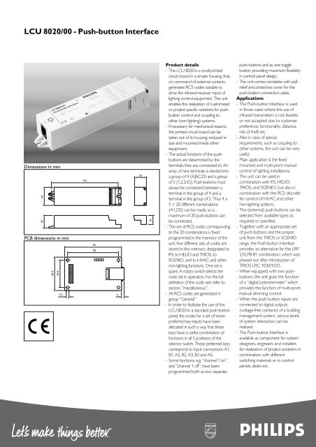
<strong>LCU</strong> <strong>8020</strong>/<strong>00</strong> - <strong>Push</strong>-<strong>button</strong> <strong>Interface</strong><br />
Dimensions in mm<br />
40<br />
28<br />
PCB dimensions in mm<br />
36.6<br />
29.9<br />
142<br />
3.5 4<br />
63<br />
56<br />
25<br />
19<br />
Product details<br />
- The <strong>LCU</strong> <strong>8020</strong> is a small printed<br />
circuit board in a simple housing, that,<br />
on command of external contacts,<br />
generates RC5 codes suitable to<br />
drive the infrared receiver input of<br />
lighting control equipment. The unit<br />
enables the realization of customized<br />
or project specific solutions for push<strong>button</strong><br />
control and coupling to<br />
other (non-lighting) systems.<br />
- If necessary for mechanical reasons,<br />
the printed circuit board can be<br />
taken out of its housing, reduced in<br />
size and mounted inside other<br />
equipment.<br />
- The actual functions of the push<strong>button</strong>s<br />
are determined by the<br />
terminals they are connected to. An<br />
array of nine terminals is divided into<br />
a group of 4 (A,B,C,D) and a group<br />
of 5 (1,2,3,4,5). <strong>Push</strong>-<strong>button</strong>s must<br />
always be connected between a<br />
terminal in the group of 4 and a<br />
terminal in the group of 5. Thus 4 x<br />
5 = 20 different combinations<br />
(A1..D5) can be made, so a<br />
maximum of 20 push-<strong>button</strong>s can<br />
be connected.<br />
- The set of RC5 codes corresponding<br />
to the 20 combinations is fixed<br />
programmed in the memory of the<br />
unit. Five different sets of codes are<br />
stored in this memory, designated to<br />
IFS, to HELIO and TRIOS, to<br />
SCENIO, and to HVAC and other<br />
non-lighting functions. One set is<br />
spare. A rotary switch selects the<br />
code set in operation. For the full<br />
definition of the code sets refer to<br />
section ”miscellaneous”.<br />
- All RC5 codes are generated in<br />
group ”General”.<br />
- In order to facilitate the use of the<br />
<strong>LCU</strong> <strong>8020</strong> in a standard push-<strong>button</strong><br />
panel, the codes for a set of seven<br />
preferred key-inputs have been<br />
allocated in such a way that these<br />
keys have a useful combination of<br />
functions in all 5 positions of the<br />
selector switch. These preferred keys<br />
correspond to input connections A1,<br />
B1, A2, B2, A3, B3 and A5.<br />
- Some functions, e.g. ”channel 1 on”<br />
and ”channel 1 off”, have been<br />
programmed both as two separate<br />
push-<strong>button</strong>s and as one toggle<br />
<strong>button</strong>, providing maximum flexibility<br />
in control panel design.<br />
- The unit comes complete with pullrelief<br />
and protective cover for the<br />
push-<strong>button</strong> connection cable.<br />
Applications<br />
- The <strong>Push</strong>-<strong>button</strong> <strong>Interface</strong> is used<br />
in those cases where the use of<br />
infrared transmitters is not feasible<br />
or not accepted due to customer<br />
preference, functionality, distance,<br />
risk of theft etc.<br />
- Also in case of special<br />
requirements, such as coupling to<br />
other systems, the unit can be very<br />
useful.<br />
- Main application is the fixed<br />
mounted and multi-point manual<br />
control of lighting installations.<br />
- The unit can be used in<br />
combination with IFS, HELIO,<br />
TRIOS, and SCENIO, but also in<br />
combination with the RC5 decoder<br />
for control of HVAC and other<br />
non-lighting systems.<br />
- The (external) push-<strong>button</strong>s can be<br />
selected from available types as<br />
required or specified.<br />
- Together with an appropriate set<br />
of push-<strong>button</strong>s and the proper<br />
unit from the TRIOS or SCENIO<br />
range, the <strong>Push</strong>-<strong>button</strong> <strong>Interface</strong><br />
provides an alternative for the LRP<br />
23/LPB 81 combination, which was<br />
phased out after introduction of<br />
TRIOS LRC 1030/1035.<br />
- When equipped with two push<strong>button</strong>s,<br />
the unit gives the function<br />
of a ”digital potentiometer” which<br />
provides the function of multi-point<br />
manual dimming control.<br />
- When the push-<strong>button</strong> inputs are<br />
connected to digital outputs<br />
(voltage-free contacts) of a building<br />
management system, various levels<br />
of system interaction can be<br />
realized.<br />
- The <strong>Push</strong>-<strong>button</strong> <strong>Interface</strong> is<br />
available as component for system<br />
designers, engineers and installers<br />
for realization of project solutions in<br />
combination with different<br />
switching materials or in control<br />
panels, desks etc.
<strong>LCU</strong> <strong>8020</strong>/<strong>00</strong> - <strong>Push</strong>-<strong>button</strong> <strong>Interface</strong><br />
Related equipment<br />
<strong>Lighting</strong> Management Systems:<br />
IFS: local units BLU 10/11, BLU 10/12, BLU 10/13<br />
DLU 10/01, DLU 10/31, LRC 4070<br />
HELIO: light controller LRC 5040<br />
Stand-alone control:<br />
TRIOS: light controllers LRC 1010, LRC 1020, LRC 1030<br />
LRC 1015, LRC 1025, LRC 1035<br />
SCENIO: light controller LRC 1555<br />
extension module LRC 1505<br />
General Purpose Components:<br />
cables: sensor cables LCC 8011, LCC 8012, LCC 8013, LCC 8014,<br />
branching connector LCC 8024<br />
sensors: infrared receivers IRR 8124, MCS 9010, MCS 9020<br />
multi-sensor LRI 8133<br />
Input : push-<strong>button</strong> contacts<br />
(normally open)<br />
V open : 5 Vdc<br />
I closed : 250 µA<br />
t closed min. : 50 ms<br />
more push-<strong>button</strong>s on one interface : allowed<br />
more interfaces on one push-<strong>button</strong> : not allowed.<br />
Output<br />
coding : bi-phase RC5 codes<br />
output low voltage : < 1.0 V<br />
output high voltage : > 3.5 V<br />
max. output current sourced : 10 mA<br />
max. output current sinked : 0.1 mA<br />
short circuit current : 50 mA (pin 5 of modular<br />
socket connected to ground).<br />
outputs can be ”wired-or” up<br />
to a total of 6 interfaces<br />
one output can drive up<br />
to 5 controller inputs.<br />
Indicator : red LED, indicating the<br />
generation of RC5 signals<br />
Power supply : 12 Vdc ±10%, 5 mA<br />
derived from connected<br />
controller.<br />
short-circuit of supply < 1 A.<br />
Electrical connections<br />
<strong>Push</strong>-<strong>button</strong> inputs<br />
connectors : 9 pole screw connector<br />
(can be replaced by header pins)<br />
wire size : AWG 26 - 16<br />
stranded : 1.0 mm2 solid : 1.0 mm2 Technical data<br />
RC5 output : modular socket (”Telejack”)<br />
standard pinning:<br />
1. 12 Vdc supply voltage<br />
2. ground<br />
3. +5 Vdc supply voltage (n.a.)<br />
4. light sensor output signal (n.a.)<br />
5. infrared receiver output signal<br />
(RC5)<br />
6. movement detector output<br />
signal (n.a.)<br />
Housing<br />
colour : white (9<strong>00</strong>64)<br />
material : Lexan 161 R<br />
flame rating : UL 94 V2<br />
glow wire test : 750 °C (IEC 695-2-1)<br />
ball pressure<br />
Operating conditions<br />
: 125 °C (IEC 335-1)<br />
ambient temperature : +5 - +50 °C<br />
relative humidity<br />
Storage conditions<br />
: 20 - 85 %, no condensation<br />
ambient temperature : -25 - +85 °C<br />
relative humidity<br />
EMC<br />
: 10 - 95 %<br />
immunity : in accordance with EN 5<strong>00</strong>82-1<br />
radiated interference : in accordance with EN 5<strong>00</strong>81-1<br />
safety<br />
Reliability<br />
: Class III<br />
call rate : 1% per year (estimated)<br />
life time<br />
Dimensions (l x w x h)<br />
: 10 years (estimated)<br />
with housing : 159 x 40 x 28 mm<br />
without housing (small size)<br />
Weight<br />
: 67 x 36,6 x 20 mm<br />
with housing : 77 g<br />
without housing (small size)<br />
Mounting<br />
: 15 g<br />
with housing : two open-ended slots<br />
for 4 mm diameter screws<br />
without housing (small size) : 3.5 mm holes in the four<br />
corners of the PCB
<strong>LCU</strong> <strong>8020</strong>/<strong>00</strong> - <strong>Push</strong>-<strong>button</strong> <strong>Interface</strong><br />
Packing data<br />
Type<br />
Unit box<br />
Outer box<br />
Ordering data<br />
Type<br />
<strong>LCU</strong> <strong>8020</strong>/<strong>00</strong><br />
Pin Function<br />
Box dimensions<br />
(mm)<br />
165 x 45 x 35<br />
175 x 190 x 150<br />
MOQ<br />
1 Ground<br />
2 Input A<br />
3 Input B<br />
4 Input C<br />
5 Input D<br />
6 Input 1<br />
7 Input 2<br />
8 Input 3<br />
9 Input 4<br />
10 Input 5<br />
11 HVAC output 0 (see table 2)<br />
12 HVAC output 1 (see table 2)<br />
13 HVAC output 2 (see table 2)<br />
14 HVAC output 3 (see table 2)<br />
15 + 5 Vdc output (25 mA max)<br />
16 Ground<br />
Table 1: Functions of the header pins<br />
8<br />
Qty<br />
1<br />
8<br />
Ordering number<br />
9137 <strong>00</strong>3 07803<br />
Material<br />
card board<br />
card board<br />
EAN code level 1<br />
87 11559 51 6561<br />
Weight (kg)<br />
net<br />
0.1<br />
0.8<br />
gross<br />
0.15<br />
1.4<br />
EAN code level 3<br />
87 11559 51 6554<br />
Miscellaneous<br />
- To avoid synchronization problems, the use of (non-HVAC) toggle keys must be restricted to stand-alone systems e.g. TRIOS, or SCENIO. In that case<br />
it is only allowed to connect one <strong>LCU</strong><strong>8020</strong> to one or more roomcontrollers (Single Point Control). The use of other sensor types is not allowed when<br />
toggle keys are used.<br />
- The RC5 outputs of a maximum of 6 push-<strong>button</strong> interfaces may be connected in parallel, in order to realize multi-point control.(Do not use toggle<br />
keys in this application).<br />
- Maximum 3 push-<strong>button</strong> interfaces may be replaced by infrared receivers (Type IRR 8124, LRI 8133, MCS 9010 or MCS 9020), in order to realize<br />
combined push-<strong>button</strong> and infrared remote control.<br />
Note: it is not allowed to use infrared receiver type IRR 04/01 or 14/01 in parallel to a push-<strong>button</strong> interface.<br />
- One or more push-<strong>button</strong> interfaces can drive the inputs of a maximum of 5 controllers.<br />
- The maximum distance between a push-<strong>button</strong> interface and a controller is 30 meters<br />
- The maximum length of the total cable between push-<strong>button</strong> interfaces, infrared receivers and controllers is 125 meters.<br />
- The maximum length of the total cable between one or more push-<strong>button</strong>s and the push-<strong>button</strong> interface is 1<strong>00</strong> meters.<br />
- It is not allowed to connect more than one push-<strong>button</strong> interface to one push-<strong>button</strong>.<br />
- <strong>Push</strong>-<strong>button</strong>s must preferably be ”low level” types with a closed contact resistance of less than 4<strong>00</strong>0 Ohm. Switching current is 250 µA. The open line<br />
voltage is 5 Vdc. For reliable operation, the contact must be closed for more than 50 ms.<br />
- The unit may be used in combination with MCS and DFS but then special precautions have to be taken with respect to electrical safety. As the<br />
interface does not add extra safety barriers to the basic insulation of MCS and DFS, push-<strong>button</strong>s and other accessible conductive parts must be<br />
covered with supplementary insulation.<br />
- The modular socket can be replaced by a 3 pole screw connector for the connection of the RC 5 output signal and the +12 V dc power supply.<br />
- The printed circuit board allows for breaking away the part with the screw terminals, in order to reduce size for easy mounting inside other equipment.<br />
In this case header pins can be used instead of screw terminals for the connection of push-<strong>button</strong>s.<br />
- When the HVAC functions are used, 7 LED’s or a 7 segment display must be connected for user feedback of the selected setpoint. The PCB has been<br />
prepared for extra header pins for the connection of a BCD to decimal decoder or a BCD to 7 segment decoder.<br />
- For connection details of the header pins see figure 1 and tables 1 and 2 below.<br />
Setting HVAC outputs 3 2 1 0<br />
HVAC Off H H H H<br />
Setpoint 1 L L L H<br />
Setpoint 2 L L H L<br />
Setpoint 3 L L H H<br />
Setpoint 4 L H L L<br />
Setpoint 5 L H L H<br />
Setpoint 6 L H H L<br />
Setpoint 7 L H H H<br />
Table 2: Coding of the HVAC outputs<br />
1<br />
3<br />
5<br />
7<br />
9<br />
11<br />
13<br />
15<br />
2<br />
4<br />
6<br />
8<br />
10<br />
12<br />
14<br />
16<br />
Figure 1: Location of the header pins<br />
H = High state<br />
(the more positive voltage)<br />
L = Low state<br />
(the less positive voltage)<br />
Ri = 1 KOhm
<strong>LCU</strong> <strong>8020</strong>/<strong>00</strong> - <strong>Push</strong>-<strong>button</strong> <strong>Interface</strong><br />
Table 5: CODE set 3 - SCENIO<br />
A B C D<br />
1 Preset 1 30 03 Preset 2 30 04 Preset 7 30 18 Preset 8 30 19<br />
2 Preset 3 30 <strong>00</strong> Preset 4 30 07 Preset 9 30 20 Preset 10 30 21<br />
3 Down 30 42 Up 30 41 Preset 11 30 22 Preset 12 30 23<br />
Stop 30 46 Stop 30 46<br />
(toggle) (toggle)<br />
4 Preset 5 30 16 Preset 6 30 17 Preset 13 30 25 Preset 14 30 26<br />
5 All Off 30 63 Up 30 41 Down 30 42 Stop 30 46<br />
Remarks: Toggle key A3 (”Down - stop”) is automatically reset to the ”Down” position each time any other key is pressed.<br />
Toggle key B3 (”Up - stop”) is automatically reset to the ”Up” position each time any other key is pressed.<br />
This automatic reset ensures logical operation after the up or down action was stopped by one of the other keys.<br />
Table 6: CODE SET 4 - HVAC, WINDOW BLINDS, OFFICE EQUIPMENT<br />
A B C D<br />
1 Preset 1 30 51 Preset 2 30 52 HVAC 30 125 HVAC 30 125<br />
Comfort + NUM Comfort + NUM<br />
Temp. down Temp. up<br />
2 1 Off/Down 30 58 1 On/Up 30 57 Preset 1 30 51 Preset 2 30 52<br />
3 Blinds Down 30 121 Blinds Up 30 120 1 Off/Down 30 58 1 On/Up 30 57<br />
Stop 30 122 Stop 30 122<br />
(toggle) (toggle)<br />
4 Blinds Down 30 121 Blinds Up 30 120 2 Off/Down 30 62 2 On/Up 30 61<br />
5 All Off, 30 63 Blinds Stop 30 122 All Off 30 63 HVAC 30 126<br />
Absent 30 127 Absent 30 127 Standby<br />
Remarks: Toggle key A3 (”Blinds Down - Stop”) is automatically reset to the ”Blinds Down” position<br />
each time key B3 (”Blinds Up - Stop”) is pressed.<br />
Toggle key B3 (”Blinds Up - Stop”) is automatically reset to the ”Blinds Up” position<br />
each time key A3 (”Blinds Down - Stop”) is pressed.<br />
This automatic reset eliminates synchtronisation problems due to commands not generated with this push-<strong>button</strong> interface,<br />
e.g. blinds stopped by the end stop switch.<br />
Keys C5 (”All Off, Absent”) and D5 (”HVAC Stand-by”) will switch off the setpoint indication LED’s or 7 segment display.
<strong>LCU</strong> <strong>8020</strong>/<strong>00</strong> - <strong>Push</strong>-<strong>button</strong> <strong>Interface</strong><br />
Function of HVAC outputs<br />
Table 3: CODE SET 1 – IFS<br />
A B C D<br />
1 1 Off/ Down 30 58 1 On/ Up 30 57<br />
2 2 Off/ Down 30 62 2 On/ Up 30 61<br />
3 3 Off/ Down 30 60 3 On/ Up 30 59<br />
4<br />
5 All Off 30 63 1 On 30 37 2 On 30 61 3 On 30 59<br />
1 Off 30 58 2 Off 30 62 3 Off 30 60<br />
(toggle) (toggle) (toggle)<br />
Remarks: IFS commands 1,2 and 3 can also be used for HELIO and Trios channel 1, channel 2 and channel 3.<br />
Toggle keys B5, C5 and D5 are automatically reset to the "On" position, when key "All Off" (A5) is pressed.<br />
This automatic reset eliminates synchronization problems due to commands initiated by the "All Off" key.<br />
Table 4: CODE SET 2 – HELIO/ TRIOS<br />
A B C D<br />
1 Preset 1 30 51 Preset 2 30 52 Ch 3 Off/Down 30 60 Ch 3 On/Up 30 59<br />
2 Preset 3 30 48 Preset 4 30 55 Ch 4 Off/Down 30 50 Ch 4 On/Up 30 49<br />
3 Ch 1 Off/Down 30 58 Ch 1 On/Up 30 57 Ch 5 Off/Down 30 54 Ch 5 on/up 30 53<br />
4 Ch 2 Off/Down 30 62 Ch 2 On/Up 30 61 Green 30 56 Store 30 56<br />
<strong>button</strong> 30 58<br />
5 All Off 30 63 Preset 1 30 51 All Off 30 63 Preset 1 30 51<br />
All Off 30 63 Preset 2 30 52<br />
(toggle) (toggle)<br />
Remarks: HELIO and Trios command Channel 1, Channel 2 and Channel 3 can also be used for IFS 1, 2, and 3.<br />
Toggle keys B5 and D5 are automatically reset to the ”Preset 1” position when key ”All Off” (A5, C5) is pressed.<br />
This automatic reset eliminates synchronisation problems due to commands initiated by the ”All Off” key.
<strong>LCU</strong> <strong>8020</strong>/<strong>00</strong> - <strong>Push</strong>-<strong>button</strong> <strong>Interface</strong><br />
Table 7: CODE SET 5 – CENTRAL CONTROL WITH PUSH-BUTTON INTERFACE <strong>LCU</strong> <strong>8020</strong><br />
3222 636 3<strong>00</strong>81<br />
04/2<strong>00</strong>1<br />
Printed in the Netherlands<br />
Data Subject to change<br />
www.controls4lighting.com<br />
This is a special mode for use in projects only. In this mode (5) the push-<strong>button</strong> interface <strong>LCU</strong> <strong>8020</strong> can be used for central control functions. For more<br />
detailed descriptions on the functionality and the installation is referred to the TRIOS- system handbook.<br />
In the following table the general commands are displayed.<br />
Required Terminals to be connected Transmitted<br />
function to common return RC5-code<br />
A B C D<br />
Preset 1 • 30 51<br />
Preset 2 • 30 52<br />
Ch. 1 on • • 30 57<br />
Preset 3 • 30 48<br />
Ch. 2 on • • 30 61<br />
Blinds down • • 30 121<br />
Preset 4 • • • 30 55<br />
All off • 30 63<br />
Blinds up • • 30 120<br />
Ch.2 off • • 30 62<br />
Ch.3 on • • • 30 59<br />
Ch.1 off • • 30 58<br />
Ch.3 off • • • 30 60<br />
Blocking • • • 29 101<br />
Deblocking • • • • 29 102<br />
Remark:<br />
When terminals A plus B plus C are connected to the common return, a "BLOCKING" command will be sent to the TRIOS units. From that moment<br />
on, TRIOS will no longer react to any local or central command or any local sensor signal. The situation can only be released by sending the<br />
"DEBLOCKING" command (A plus B plus C plus D connected to the common return).<br />
As an exception to the rule, parallel connection of the push-<strong>button</strong> interfaces is allowed, but only when using code set 5.<br />
Related documentation<br />
Installation instructions 3222 609 26451<br />
Engineering and Service manual IFS (English) 3222 635 09491<br />
HELIO System Handbook LCH 59<strong>00</strong>/<strong>00</strong> (English) 9130 010 <strong>00</strong><strong>00</strong>3<br />
HELIO Energy Saving Handbook LCH 5915/<strong>00</strong> (English) 9137 010 <strong>00</strong>203<br />
SCENIO System Handbook LCH 1599/<strong>00</strong> (English) 9137 010 <strong>00</strong>403<br />
Technical Application Manual Trios (English) 3222 010 <strong>00</strong>403<br />
TRIOS System Handbook LCH 1099/<strong>00</strong> (English) 9137 010 <strong>00</strong>503<br />
<strong>Philips</strong><br />
<strong>Lighting</strong>