SpaceClaim 2011+
SpaceClaim 2011+
SpaceClaim 2011+

You also want an ePaper? Increase the reach of your titles
YUMPU automatically turns print PDFs into web optimized ePapers that Google loves.
<strong>SpaceClaim</strong> <strong>2011+</strong> Release Notes<br />
Creating holes in a sheet metal flat part and then including those holes completely within a bend zone<br />
now results in holes that bend up when you create a bend, as shown in the image below. Previously,<br />
holes in this design scenario did not bend up.<br />
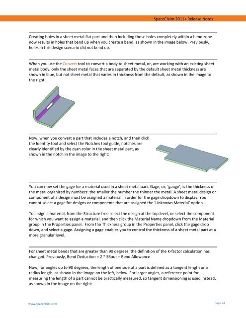
When you use the Convert tool to convert a body to sheet metal, or, are working with an existing sheet<br />
metal body, only the sheet metal faces that are separated by the default sheet metal thickness are<br />
shown in blue, but not sheet metal that varies in thickness from the default, as shown in the image to<br />
the right:<br />
Now, when you convert a part that includes a notch, and then click<br />
the Identity tool and select the Notches tool guide, notches are<br />
clearly identified by the cyan color in the sheet metal part, as<br />
shown in the notch in the image to the right:<br />
You can now set the gage for a material used in a sheet metal part. Gage, or, ‘gauge’, is the thickness of<br />
the metal organized by numbers: the smaller the number the thinner the metal. A sheet metal design or<br />
component of a design must be assigned a material in order for the gage dropdown to display. You<br />
cannot select a gage for designs or components that are assigned the ‘Unknown Material’ option.<br />
To assign a material, from the Structure tree select the design at the top level, or select the component<br />
for which you want to assign a material, and then click the Material Name dropdown from the Material<br />
group in the Properties panel. From the Thickness group in the Properties panel, click the gage drop<br />
down, and select a gage. Assigning a gage enables you to control the thickness of a sheet metal part at a<br />
more granular level.<br />
For sheet metal bends that are greater than 90 degrees, the definition of the K-factor calculation has<br />
changed. Previously, Bend Deduction = 2 * SBout – Bend Allowance<br />
Now, for angles up to 90 degrees, the length of one side of a part is defined as a tangent length or a<br />
radius length, as shown in the image on the left, below. For larger angles, a reference point for<br />
measuring the length of a part cannot be practically measured, so tangent dimensioning is used instead,<br />
as shown in the image on the right:<br />
www.spaceclaim.com<br />
Page 24