ALxxF Microwave Radio Indoor Unit (IDU) Users Manual - Meconet
ALxxF Microwave Radio Indoor Unit (IDU) Users Manual - Meconet
ALxxF Microwave Radio Indoor Unit (IDU) Users Manual - Meconet

You also want an ePaper? Increase the reach of your titles
YUMPU automatically turns print PDFs into web optimized ePapers that Google loves.
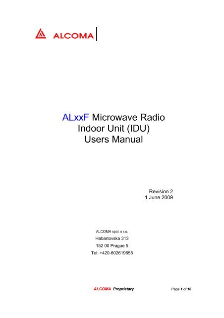
<strong>ALxxF</strong> <strong>Microwave</strong> <strong>Radio</strong><br />
<strong>Indoor</strong> <strong>Unit</strong> (<strong>IDU</strong>)<br />
<strong>Users</strong> <strong>Manual</strong><br />
ALCOMA spol. s r.o.<br />
Habartovska 313<br />
152 00 Prague 5<br />
Tel: +420-602619655<br />
Revision 2<br />
1 June 2009<br />
ALCOMA Proprietary Page 1 of 16
Table of Contents<br />
1. ALXXF PRODUCT DESCRIPTION 3<br />
1.1. Overview 3<br />
1.2.<br />
1.2.1.<br />
1.2.2.<br />
1.2.3.<br />
1.2.4.<br />
1.2.5.<br />
1.2.6.<br />
1.2.7.<br />
Front Panel Interfaces 7<br />
T1/E1 Ports.............................................................................................................................. 7<br />
Ethernet Transport Ports.......................................................................................................... 7<br />
Ethernet Management Ports .................................................................................................... 8<br />
Overhead/Hot Standby Interface ............................................................................................. 8<br />
Command Line Serial Interface .............................................................................................. 9<br />
DC Power...............................................................................................................................10<br />
ODU Interface........................................................................................................................11<br />
2. SETUP AND OPERATION 13<br />
3. CLI TEXT MENU CONTROL AND STATUS SOFTWARE INTERFACE 15<br />
ALCOMA Proprietary Page 2 of 16
1. <strong>ALxxF</strong> Product Description<br />
1.1. Overview<br />
The <strong>ALxxF</strong> serves as the <strong>Indoor</strong> <strong>Unit</strong> of a point-to-point microwave radio<br />
system designed for operation in the 7 to 38 GHz radio frequency band. Key<br />
features and functions are as follows:<br />
• Line interface and conditioning functions necessary for transport of up to<br />
four PDH T1/E1 channels<br />
• Ethernet transport via two front panel 100BaseT RJ-45 ports. The <strong>IDU</strong><br />
can be configured for standalone Ethernet transport, or a combination of<br />
T1/E1 and Ethernet transport. VLAN security features and Ethernet port<br />
rate controls.<br />
• Digital modem functions with configurable modulation modes of QPSK,<br />
16QAM, 32QAM, 64QAM, 128QAM and 256QAM.<br />
• Configurable forward error correction with settable interleaver depth<br />
(latency)<br />
• Management interfaces include front panel RS-232 serial port and two<br />
Management Ethernet ports and Web based GUI interface.<br />
o Web based security user authentication<br />
o Advanced link performance monitoring, including data log and<br />
event logs<br />
o Downloadable firmware upgrade feature via Ethernet<br />
management ports<br />
o Link status display of local and remote terminals<br />
o Local and remote control of terminals via Ethernet management<br />
ports<br />
o Software selection of multiple versions of ODU’s<br />
• On-board Ethernet Switch together with dual management Ethernet ports<br />
supports daisy-chaining of Ethernet Management<br />
• Overhead admin serial channel interface (transported as side-channel<br />
over the link)<br />
• SNMP alarm features and user settable heartbeat for use with trap server.<br />
• Two FormC general purpose relays. Two Alarm Bi-level inputs<br />
• Hot Standby control and status interface allows for Protected Mode<br />
operation.<br />
ALCOMA Proprietary Page 3 of 16
• Wide-mouth 21 to 60V DC Power interface is configurable via internal<br />
switch for negative or positive voltage operation 1<br />
• All Outdoor <strong>Unit</strong> (ODU) interface signals are multiplexed onto front-panel<br />
N-type connector interface<br />
• Front panel LEDs indicate Power-on, Alarm and Fault status<br />
1<br />
Prototype DC power polarity configured via jumpers on Power Converter Board. Production version<br />
will replace jumpers with slide switch.<br />
ALCOMA Proprietary Page 4 of 16
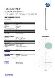
ODU I/F<br />
(N-Type)<br />
BPF<br />
BPF<br />
BPF<br />
BPF<br />
LPF<br />
Power<br />
Conversion<br />
DC Power<br />
+V<br />
-V<br />
GND<br />
ADC<br />
DAC<br />
ASK Tlm<br />
Demod<br />
ASK Cmd<br />
Mod<br />
Relay Controls<br />
Relay<br />
3 3<br />
Alarm Bi-level Inputs<br />
HSBY/Aux (DB-26)<br />
Signal Processing<br />
Admin. OH Serial Channel<br />
HSBY I/O<br />
2 2 4<br />
Proc Bus<br />
µP<br />
Craft (DB-9)<br />
Figure 1 <strong>ALxxF</strong> Functional Block Diagram<br />
MII<br />
MDC<br />
MII<br />
Ethernet<br />
Switch<br />
Quad<br />
Magnetics<br />
Quad Ethernet<br />
RJ-45 Ports<br />
E1/T1<br />
LIU<br />
Quad<br />
Magnetics<br />
Quad E1/T1<br />
RJ-48 Ports<br />
ALCOMA Proprietary Page 5 of 16<br />
MDC<br />
Data I/O<br />
Expansion<br />
Interface<br />
Cntrl/Status
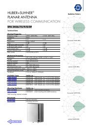
DC Power<br />
F1 F2<br />
ODU<br />
Power<br />
Alarm<br />
Fault<br />
CLI<br />
Modem<br />
OH/Hsby<br />
Eth<br />
Mgmt<br />
Eth<br />
Mgmt<br />
Eth<br />
1<br />
Eth<br />
2<br />
T1/E1<br />
P1<br />
T1/E1<br />
P2<br />
T1/E1<br />
P3<br />
T1/E1<br />
P4<br />
Figure 2 ALXXF Front Panel<br />
ALCOMA Proprietary Page 6 of 16
1.2. Front Panel Interfaces<br />
1.2.1. T1/E1 Ports<br />
The T1/E1 ports are 8-pin modular jacks with standard RJ-48 pinouts as<br />
shown in Figure 3 and Table 1 below. Transport mode is software<br />
configurable to support one to four T1 channels or 1 to 4 E1 channels. Lines<br />
are matched to 100 ohm in T1 mode and 120 ohm in E1 mode.<br />
Figure 3 Pin Definition for 8-pin Modular Jack (as seen looking into the port)<br />
1.2.2. Ethernet Transport Ports<br />
Pin Signal Name<br />
1 RX, Ring, -<br />
2 RX, Tip, +<br />
3 Shield/Return/Gnd<br />
4 TX, Ring, -<br />
5 TX, Tip, +<br />
6 Shield/Return/Gnd<br />
7 NC<br />
8 NC<br />
Table 1 T1/E1 RJ-48 Pinout<br />
The two Ethernet transport ports (Enet-1 and Enet-2) provide 10/100BaseT<br />
interfaces with standard RJ-45 pinouts. When the <strong>IDU</strong> is properly configured,<br />
the <strong>IDU</strong> provides transport of Ethernet frames ingressed at these ports over<br />
the link to the far side radio. An internal Ethernet switch also provides layer 2<br />
switching functions between these two ports and the far side terminal. The<br />
Ethernet PHYs provide MDI/MDI-X cross-connect with auto-detect, so both<br />
straight-thru and cross cables are accommodated to any other 10/100 Base-<br />
T interface. Ethernet transport is configurable up to 130 Mbps.<br />
Note that Ethernet transport will be enabled with a coming firmware<br />
update.<br />
ALCOMA Proprietary Page 7 of 16
1.2.3. Ethernet Management Ports<br />
The two Ethernet management ports (Mgmt-1 and Mgmt-2) provide<br />
10/100BaseT interfaces to the <strong>IDU</strong>’with standard RJ-45 pinouts. These ports<br />
allow management access to the <strong>IDU</strong>’s internal CPU. An internal Ethernet<br />
switch also provides layer 2 switching functions between these two ports and<br />
the far side terminal. The Ethernet PHYs provide MDI/MDI-X cross-connect<br />
with auto-detect, so both straight-thru and cross cables are accommodated to<br />
any other 10/100 Base-T interface.<br />
Note that Ethernet-based management is not yet enabled on the<br />
prototypes. These functions will be enabled with a future firmware update.<br />
1.2.4. Overhead/Hot Standby Interface<br />
The Overhead and Hot Standby signals are provided over a DB-26 interface<br />
with connector pinouts and signal assignments as defined in Figure 4 and<br />
Table 2 below.<br />
9<br />
26<br />
Figure 4 Pinout for High-density DB-26 Connector (as seen looking at front panel)<br />
1<br />
19<br />
ALCOMA Proprietary Page 8 of 16
Pin Signal Name Description<br />
1 Chassis Ground Ground<br />
2 Aux Serial Receive Aux Serial Channel Rx Data (to <strong>IDU</strong>)<br />
3 Hot Standby 5V Power 5V Power to HSBY Shelf<br />
4 Hot Standby SPI MISO SPI communication bus to/from HSBY Shelf<br />
5 Chassis Ground Ground<br />
6 Hot Standby Serial Transmit Serial communication to HSBY Shelf<br />
7 Hot Standby Shelf Present HSBY Shelf present signal<br />
8 Relay 2 COM Relay 2 COM pin<br />
9 Relay 1 NC Relay 1 NC pin<br />
10 Aux Serial Transmit Aux Serial Channel Tx Data (from <strong>IDU</strong>)<br />
11 Chassis Ground Ground<br />
12 Hot Standby SPI Clock SPI communication bus to/from HSBY Shelf<br />
13 Hot Standby 3.3V Power 3.3V Power to HSBY Shelf<br />
14 Hot Standby Serial Receive Serial communication from HSBY Shelf<br />
15 Chassis Ground Ground<br />
16 Aux Alarm Input 2 Bi-level alarm 2 input<br />
17 Relay 1 NO Relay 1 NO pin<br />
18 Relay 2 NC Relay 2 NC pin<br />
19 Chassis Ground Ground<br />
20 Hot Standby SPI Sel SPI communication bus to/from HSBY Shelf<br />
21 Hot Standby 5V Power 5V Power to HSBY Shelf<br />
22 Hot Standby SPI MOSI SPI communication bus to/from HSBY Shelf<br />
23 Chassis Ground Ground<br />
24 Aux Alarm Input 1 Bi-level alarm 1 input<br />
25 Relay 2 NO Relay 2 NO pin<br />
26 Relay 1 COM Relay 1 COM pin<br />
Table 2 Overhead/Hot Standby Interface Connector Pinout<br />
1.2.5. Command Line Serial Interface<br />
The CLI interface presents a standard three-wire RS-232 DCE interface on a<br />
female DB-9 connector with connector pinouts and signal assignments as<br />
defined in Figure 5 and Table 3 below. The CLI interface is configured as<br />
follows:<br />
ALCOMA Proprietary Page 9 of 16
• Data rate: 57600 bps<br />
• 1 start bit<br />
• 8 data bits<br />
• No parity<br />
• 1 stop bit<br />
5<br />
9<br />
Figure 5 Pin Definitions for Female 9 Pin Sub-D Connector (as seen by looking at<br />
front panel)<br />
Pin # Signal Name Direction Signal Description<br />
1 NC<br />
2 TXD Out Transmit Data (from <strong>IDU</strong>)<br />
3 RXD In Receive Data (to <strong>IDU</strong>)<br />
4 NC<br />
5 GND N/A Ground<br />
6 NC<br />
7 NC<br />
8 NC<br />
9 NC<br />
1.2.6. DC Power<br />
Table 3 CLI Connector Pinout<br />
6<br />
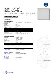
DC Power is provided via a three terminal connector, as indicated in Figure 6.<br />
A switch internal to the <strong>IDU</strong> must be set to the desired polarity.<br />
For positive voltage operation:<br />
• Internal power switch must be set for “+24V” operation<br />
• Connect positive terminal of external supply to “+V” terminal of<br />
ALXXF<br />
• Connect negative terminal of external supply to “-V” terminal of<br />
ALXXF.<br />
• Connect negative terminal of external supply to “GND” terminal of<br />
ALXXF.<br />
1<br />
ALCOMA Proprietary Page 10 of 16
For negative voltage operation:<br />
• Internal power switch must be set for “-48V” operation<br />
• Connect negative terminal of external supply to “-V” terminal of<br />
ALXXF<br />
• Connect positive terminal of external supply to “+V” terminal of<br />
ALXXF.<br />
• Connect positive terminal of external supply to “GND” terminal of<br />
ALXXF.<br />
+V -V GND<br />
Figure 6 DC Power Connector (as seen from front panel)<br />
Two fuses are accessible from the front panel. One fuse (labeled F1 in<br />
Figure 2) provides short circuit protection when the <strong>IDU</strong> is configured for<br />
positive voltage operation; the second fuse (F2) provides short circuit<br />
protection when configured for negative voltage operation. In both cases, the<br />
fuse protects both the <strong>IDU</strong> and the ODU. The fuse holders accommodate<br />
standard 5 x 20 mm fuses. ALXXF units are delivered with 7A fast-acting<br />
fuses installed.<br />
A simplified block diagram of the power converter is provided as Figure 7,<br />
depicting the function of the polarity selection switches and the positioning of<br />
the fuses. In addition to the protection fuses, the production version will also<br />
include electronic protection circuitry designed to protect against certain kinds<br />
of short-circuit events without resulting in blowing either fuse. (Note that this<br />
electronic over-current protection is not yet active in the Prototype <strong>Unit</strong>s.)<br />
1.2.7. ODU Interface<br />
The N-Type ODU interface multiplexes the following signals:<br />
• DC power (with polarity determined by internal switch setting as<br />
discussed in Section 1.2.6).<br />
• Transmit modulated IF signal at center frequency 350 MHz (to<br />
ODU)<br />
• Receive modulated IF signal at center frequency 140 MHz (from<br />
ODU)<br />
• OOK ODU command signal at 5.5 MHz center frequency<br />
• OOK ODU telemetry signal at 10 MHz center frequency<br />
ALCOMA Proprietary Page 11 of 16
+V<br />
-V<br />
GND<br />
F1<br />
F2<br />
Pol Sense/ Inrush<br />
Limiting<br />
Pol Sense/ Inrush<br />
Limiting/ OV Prot.<br />
Isolated 5V<br />
Converter<br />
Figure 7 ALXXF Power Converter Simplified Block Diagram<br />
Secondary<br />
Converters<br />
DC to ODU<br />
DC Supply to <strong>IDU</strong><br />
ALCOMA Proprietary Page 12 of 16
2. Setup and Operation<br />
To setup a link for operation, proceed with the following steps at each end of the<br />
link:<br />
1. Prior to operation, make certain that <strong>IDU</strong> is configured (via internal switch<br />
setting) to DC Power polarity required by the ODU. The factory<br />
configuration of the <strong>IDU</strong> is indicated via marking on the back of the <strong>IDU</strong>.<br />
WARNING: FAILURE TO FOLLOW THIS STEP MAY DAMAGE THE<br />
ODU.<br />
2. Prior to connecting DC power to the <strong>IDU</strong>, connect the <strong>IDU</strong> and ODU via a<br />
50 ohm coaxial cable.<br />
3. Connect the CLI port to a terminal emulator with settings as defined in<br />
Section 1.2.5.<br />
4. Connect an external DC power supply to the <strong>IDU</strong> front panel interface.<br />
Make certain that the polarity of the external supply matches the<br />
configuration of the <strong>IDU</strong> (see Section 1.2.6 for details).<br />
5. Configure the <strong>IDU</strong> to the desired transport mode via the text menu<br />
interface, as described in Section 3. For example, to configure the <strong>IDU</strong> for<br />
Two T1 Channel Transport, make the following menu selections:<br />
• From the Main Menu select “1) <strong>IDU</strong> Control / Status”<br />
• From the <strong>IDU</strong> Control / Status Menu, select “1) Link Configuration”<br />
• From the Link Configuration Menu, select “2” for 2DS1 (T1)<br />
operation. All aspects of the <strong>IDU</strong> (line interfaces, modulation mode,<br />
FEC, etc…) are automatically configured from this selection.<br />
6. Enter “X” repeatedly to return to the Main Menu.<br />
7. Configure the ODU as desired:<br />
• From the Main Menu select “2) ODU Control / Status”<br />
• From the ODU Control / Status Menu, configure Tx Power, Tx<br />
Channel, and Rx Channel as desired, then enable Tx Power<br />
Enable. (Note that the software is currently designed such that<br />
ODU PA Tx must be explicitly enabled. The software can be<br />
modified to automatically enable the ODU Tx PA upon turn-on if<br />
desired by EMS.)<br />
When both ends of the link have been configured to the same (or consistent)<br />
configurations, acquisition is automatic on both sides. Many aspects of the <strong>IDU</strong><br />
status are available via the “Link Status” selection under the “<strong>IDU</strong> Control /<br />
ALCOMA Proprietary Page 13 of 16
Status” menu. ODU status is available via the “Display Status” menu under the<br />
ODU Control / Status menu.<br />
The table shows the total number of E1’s that can be configured, total data speed<br />
for each type of modulation and bandwidth are shown. All bandwidth not used<br />
for E1 transport can be assigned for Ethernet transport with the iAM-ALXXF <strong>IDU</strong>.<br />
The Ethernet looks like a single port to the modem. The Ethernet switch can be<br />
programmed to rate limit any, each, or all of its ports. If you don’t limit the input<br />
rate, it will process what it can based on the modem configuration.<br />
Modulation 7.0<br />
B CHANNEL = Channel Bandwidth (MHz)<br />
14.0 28.0<br />
QPSK<br />
16 QAM<br />
32 QAM<br />
64 QAM<br />
4E1<br />
8Mbps<br />
4E1<br />
16Mbps<br />
4E1<br />
16Mbps<br />
4E1<br />
34 Mbps<br />
4E1<br />
34 Mbps<br />
4E1<br />
34 Mbps<br />
4E1<br />
68 Mbps<br />
4E1<br />
68 Mbps<br />
4E1<br />
130 Mbps<br />
ALCOMA Proprietary Page 14 of 16
3. CLI Text Menu Control and Status Software Interface<br />
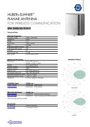
The prototype Command Line Interface is a simple scrolling Text Menu interface<br />
with structure as depicted in Figure 8. To proceed down any path of the menu<br />
hierarchy, enter the indicated alphanumeric followed by the Return key. From<br />
anywhere in the menu, proceed back up the hierarchy by entering the letter “X”<br />
followed by the Return key.<br />
ALCOMA Proprietary Page 15 of 16
Link Configuration :<br />
Capacity Mod Type<br />
1) 1DS1 QPSK<br />
2) 1DS1 16QAM<br />
3) 1DS1 32QAM<br />
4) 1DS1 64QAM<br />
5) 2DS1 16QAM<br />
6) 2DS1 32QAM<br />
7) 2DS1 64QAM<br />
8) 3DS1 32QAM<br />
9) 3DS1 64QAM<br />
10) 4DS1 64QAM<br />
21) 1E1 QPSK<br />
22) 1E1 16QAM<br />
23) 1E1 32QAM<br />
24) 1E1 64QAM<br />
25) 2E1 16QAM<br />
26) 2E1 32QAM<br />
27) 2E1 64QAM<br />
28) 3E1 32QAM<br />
<strong>IDU</strong> Control / Status:<br />
1) Link Configuration<br />
2) Link Status<br />
3) Enable Aggreate Loopback<br />
4) Enable Aggreate BERT<br />
5) Expert Menu<br />
6) Save Current Configuration<br />
X) Exit<br />
1<br />
2<br />
1<br />
ODU Control / Status:<br />
1) Set TX Enable<br />
2) Set TX Power<br />
3) Set TX Frequency<br />
4) Set TX Channel<br />
5) Set RX Frequency<br />
6) Set RX Channel<br />
7) Display Version<br />
S) Save Settings<br />
R) Restore Factory<br />
U) Update Status<br />
X) Exit<br />
Link Status:<br />
1) Modem State<br />
2) Modem Configuration<br />
3) Modem Operational Status<br />
4) Modem Link Quality Status<br />
5) Modem BERT Status<br />
6) Loopback/BERT Status<br />
7) LIM A Operational Status<br />
8) LIM B Operational Status<br />
9) LIM A Link Quality Status<br />
A) LIM B Link Quality Status<br />
B) Overhead Link Quality Stats<br />
C) Demod Status<br />
D) RS Decoder Status<br />
E) Constellation<br />
W) Weights<br />
R) Reset Statistics<br />
X) Exit<br />
Main Menu:<br />
1) <strong>IDU</strong> Control / Status<br />
2) ODU Control / Status<br />
3) Loopbacks<br />
4) BER Testing<br />
5) Test Signals<br />
6) Utilities<br />
2 3<br />
Loopbacks:<br />
1) Modem Loopback Mode<br />
2) Lim A Loopback Mode<br />
3) Lim B Loopback Mode<br />
X) Exit<br />
2 or 3 (Enter Line # 0)<br />
LIM Loopback :<br />
1) Disable Loopback<br />
2) Line-Side Digital Loopback<br />
3) <strong>Radio</strong>-Side Analog Loopback<br />
4) <strong>Radio</strong>-Side Digital Loopback<br />
X) Exit<br />
4<br />
BER Testing:<br />
1) LIM A BERT Tx Mode<br />
2) LIM B BERT Tx Mode<br />
3) LIM A BERT Rx Line Select<br />
4) LIM B BERT Rx Line Select<br />
X) Exit<br />
Figure 8 CLI Text Menu Description<br />
5<br />
Test Signals:<br />
1) Transmit single tone<br />
2) Transmit two tone<br />
3) Sweep single tone<br />
4) Sweep single tone and capture ADC<br />
5) Sweep single tone and capture loopback<br />
6) Sweep single tone and capture receiver<br />
7) Capture ADC<br />
8) Capture loopback<br />
9) Capture receiver<br />
A) Capture receiver (Symbols)<br />
X) Exit<br />
Utilities:<br />
1) LEDs<br />
2) REAL TIME CLOCK<br />
3) I2C DEVICES<br />
4) IF PROCESSOR<br />
5) MEMORY DUMPS<br />
6) MODEM TEST<br />
7) FLASH UTILITIES<br />
X) Exit<br />
ALCOMA Proprietary Page 16 of 16<br />
6