R&S FSQ Signal Analyzer - Rohde & Schwarz
R&S FSQ Signal Analyzer - Rohde & Schwarz
R&S FSQ Signal Analyzer - Rohde & Schwarz

You also want an ePaper? Increase the reach of your titles
YUMPU automatically turns print PDFs into web optimized ePapers that Google loves.
R&S ® <strong>FSQ</strong><br />
<strong>Signal</strong> <strong>Analyzer</strong><br />
Operating Manual<br />
1313.9681.12 – 01<br />
Test & Measurement<br />
Operating Manual
The Operating Manual describes the following R&S ® <strong>FSQ</strong> models and options:<br />
● R&S <strong>FSQ</strong> (1313.9100.xx) with CF Card (R&S FSU-B18 )<br />
● R&S <strong>FSQ</strong> (1155.5001.xx) with 3.5 disk drive, 1.44 MByte<br />
● R&S FSU-B9 (1142.8994.02)<br />
● R&S <strong>FSQ</strong>-B10 (1129.7246.03)<br />
● R&S FSP-B16 (1129.8042.03)<br />
● R&S <strong>FSQ</strong>-B17 (1163.0063.02)<br />
● R&S FSU-B18 (1303.0400.13)<br />
● R&S FSU-B21 (1157.1090.03)<br />
The contents of this manual correspond to firmware 4.65 or higher.<br />
© 2011 <strong>Rohde</strong> & <strong>Schwarz</strong> GmbH & Co. KG<br />
Muehldorfstr. 15, 81671 Munich. Germany<br />
Phone: +49 89 4129-0<br />
Fax: +49 89 4129-12 164<br />
E-mail: info@rohde-schwarz.com<br />
Internet: http://www.rohde-schwarz.com<br />
81671 Munich, Germany<br />
Printed in Germany – Subject to change – Data without tolerance limits is not binding.<br />
R&S ® is a registered trademark of <strong>Rohde</strong> & <strong>Schwarz</strong> GmbH & Co. KG.<br />
Trade names are trademarks of the owners.<br />
The following abbreviations are used throughout this manual:<br />
R&S ® <strong>FSQ</strong> is abbreviated as R&S <strong>FSQ</strong>.
Basic Safety Instructions<br />
Always read through and comply with the following safety instructions!<br />
All plants and locations of the <strong>Rohde</strong> & <strong>Schwarz</strong> group of companies make every effort to keep the safety<br />
standards of our products up to date and to offer our customers the highest possible degree of safety. Our<br />
products and the auxiliary equipment they require are designed, built and tested in accordance with the<br />
safety standards that apply in each case. Compliance with these standards is continuously monitored by<br />
our quality assurance system. The product described here has been designed, built and tested in<br />
accordance with the attached EC Certificate of Conformity and has left the manufacturer’s plant in a<br />
condition fully complying with safety standards. To maintain this condition and to ensure safe operation,<br />
you must observe all instructions and warnings provided in this manual. If you have any questions<br />
regarding these safety instructions, the <strong>Rohde</strong> & <strong>Schwarz</strong> group of companies will be happy to answer<br />
them.<br />
Furthermore, it is your responsibility to use the product in an appropriate manner. This product is designed<br />
for use solely in industrial and laboratory environments or, if expressly permitted, also in the field and must<br />
not be used in any way that may cause personal injury or property damage. You are responsible if the<br />
product is used for any intention other than its designated purpose or in disregard of the manufacturer's<br />
instructions. The manufacturer shall assume no responsibility for such use of the product.<br />
The product is used for its designated purpose if it is used in accordance with its product documentation<br />
and within its performance limits (see data sheet, documentation, the following safety instructions). Using<br />
the product requires technical skills and a basic knowledge of English. It is therefore essential that only<br />
skilled and specialized staff or thoroughly trained personnel with the required skills be allowed to use the<br />
product. If personal safety gear is required for using <strong>Rohde</strong> & <strong>Schwarz</strong> products, this will be indicated at<br />
the appropriate place in the product documentation. Keep the basic safety instructions and the product<br />
documentation in a safe place and pass them on to the subsequent users.<br />
Observing the safety instructions will help prevent personal injury or damage of any kind caused by<br />
dangerous situations. Therefore, carefully read through and adhere to the following safety instructions<br />
before and when using the product. It is also absolutely essential to observe the additional safety<br />
instructions on personal safety, for example, that appear in relevant parts of the product documentation. In<br />
these safety instructions, the word "product" refers to all merchandise sold and distributed by the <strong>Rohde</strong> &<br />
<strong>Schwarz</strong> group of companies, including instruments, systems and all accessories.<br />
Symbols and safety labels<br />
Notice, general<br />
danger location<br />
Observe product<br />
documentation<br />
ON/OFF supply<br />
voltage<br />
Caution<br />
when<br />
handling<br />
heavy<br />
equipment<br />
Standby<br />
indication<br />
Danger of<br />
electric<br />
shock<br />
Direct current<br />
(DC)<br />
Warning!<br />
Hot surface<br />
Alternating current<br />
(AC)<br />
PE terminal Ground Ground<br />
terminal<br />
Direct/alternating<br />
current (DC/AC)<br />
Be careful when<br />
handling<br />
electrostatic<br />
sensitive<br />
devices<br />
Device fully protected by<br />
double (reinforced) insulation<br />
1171.0000.42-05.00 Page 1
Tags and their meaning<br />
Basic Safety Instructions<br />
The following signal words are used in the product documentation in order to warn the reader about risks<br />
and dangers.<br />
indicates a hazardous situation which, if not avoided, will result in death or<br />
serious injury.<br />
indicates a hazardous situation which, if not avoided, could result in death or<br />
serious injury.<br />
indicates a hazardous situation which, if not avoided, could result in minor or<br />
moderate injury.<br />
indicates the possibility of incorrect operation which can result in damage to<br />
the product.<br />
In the product documentation, the word ATTENTION is used synonymously.<br />
These tags are in accordance with the standard definition for civil applications in the European Economic<br />
Area. Definitions that deviate from the standard definition may also exist in other economic areas or<br />
military applications. It is therefore essential to make sure that the tags described here are always used<br />
only in connection with the related product documentation and the related product. The use of tags in<br />
connection with unrelated products or documentation can result in misinterpretation and in personal injury<br />
or material damage.<br />
Operating states and operating positions<br />
The product may be operated only under the operating conditions and in the positions specified by the<br />
manufacturer, without the product's ventilation being obstructed. If the manufacturer's specifications are<br />
not observed, this can result in electric shock, fire and/or serious personal injury or death. Applicable local<br />
or national safety regulations and rules for the prevention of accidents must be observed in all work<br />
performed.<br />
1. Unless otherwise specified, the following requirements apply to <strong>Rohde</strong> & <strong>Schwarz</strong> products:<br />
predefined operating position is always with the housing floor facing down, IP protection 2X, pollution<br />
severity 2, overvoltage category 2, use only indoors, max. operating altitude 2000 m above sea level,<br />
max. transport altitude 4500 m above sea level. A tolerance of ±10 % shall apply to the nominal<br />
voltage and ±5 % to the nominal frequency.<br />
2. Do not place the product on surfaces, vehicles, cabinets or tables that for reasons of weight or stability<br />
are unsuitable for this purpose. Always follow the manufacturer's installation instructions when<br />
installing the product and fastening it to objects or structures (e.g. walls and shelves). An installation<br />
that is not carried out as described in the product documentation could result in personal injury or<br />
death.<br />
3. Do not place the product on heat-generating devices such as radiators or fan heaters. The ambient<br />
temperature must not exceed the maximum temperature specified in the product documentation or in<br />
the data sheet. Product overheating can cause electric shock, fire and/or serious personal injury or<br />
death.<br />
1171.0000.42-05.00 Page 2
Electrical safety<br />
Basic Safety Instructions<br />
If the information on electrical safety is not observed either at all to the extent necessary, electric shock,<br />
fire and/or serious personal injury or death may occur.<br />
1. Prior to switching on the product, always ensure that the nominal voltage setting on the product<br />
matches the nominal voltage of the AC supply network. If a different voltage is to be set, the power<br />
fuse of the product may have to be changed accordingly.<br />
2. In the case of products of safety class I with movable power cord and connector, operation is<br />
permitted only on sockets with an earthing contact and protective earth connection.<br />
3. Intentionally breaking the protective earth connection either in the feed line or in the product itself is<br />
not permitted. Doing so can result in the danger of an electric shock from the product. If extension<br />
cords or connector strips are implemented, they must be checked on a regular basis to ensure that<br />
they are safe to use.<br />
4. If the product does not have a power switch for disconnection from the AC supply network, the plug of<br />
the connecting cable is regarded as the disconnecting device. In such cases, always ensure that the<br />
power plug is easily reachable and accessible at all times (corresponding to the length of connecting<br />
cable, approx. 2 m). Functional or electronic switches are not suitable for providing disconnection from<br />
the AC supply network. If products without power switches are integrated into racks or systems, a<br />
disconnecting device must be provided at the system level.<br />
5. Never use the product if the power cable is damaged. Check the power cable on a regular basis to<br />
ensure that it is in proper operating condition. By taking appropriate safety measures and carefully<br />
laying the power cable, you can ensure that the cable will not be damaged and that no one can be<br />
hurt by, for example, tripping over the cable or suffering an electric shock.<br />
6. The product may be operated only from TN/TT supply networks fused with max. 16 A (higher fuse<br />
only after consulting with the <strong>Rohde</strong> & <strong>Schwarz</strong> group of companies).<br />
7. Do not insert the plug into sockets that are dusty or dirty. Insert the plug firmly and all the way into the<br />
socket. Otherwise, sparks that result in fire and/or injuries may occur.<br />
8. Do not overload any sockets, extension cords or connector strips; doing so can cause fire or electric<br />
shocks.<br />
9. For measurements in circuits with voltages Vrms > 30 V, suitable measures (e.g. appropriate<br />
measuring equipment, fusing, current limiting, electrical separation, insulation) should be taken to<br />
avoid any hazards.<br />
10. Ensure that the connections with information technology equipment, e.g. PCs or other industrial<br />
computers, comply with the IEC60950-1/EN60950-1 or IEC61010-1/EN 61010-1 standards that apply<br />
in each case.<br />
11. Unless expressly permitted, never remove the cover or any part of the housing while the product is in<br />
operation. Doing so will expose circuits and components and can lead to injuries, fire or damage to the<br />
product.<br />
12. If a product is to be permanently installed, the connection between the PE terminal on site and the<br />
product's PE conductor must be made first before any other connection is made. The product may be<br />
installed and connected only by a licensed electrician.<br />
13. For permanently installed equipment without built-in fuses, circuit breakers or similar protective<br />
devices, the supply circuit must be fused in such a way that anyone who has access to the product, as<br />
well as the product itself, is adequately protected from injury or damage.<br />
1171.0000.42-05.00 Page 3
Basic Safety Instructions<br />
14. Use suitable overvoltage protection to ensure that no overvoltage (such as that caused by a bolt of<br />
lightning) can reach the product. Otherwise, the person operating the product will be exposed to the<br />
danger of an electric shock.<br />
15. Any object that is not designed to be placed in the openings of the housing must not be used for this<br />
purpose. Doing so can cause short circuits inside the product and/or electric shocks, fire or injuries.<br />
16. Unless specified otherwise, products are not liquid-proof (see also section "Operating states and<br />
operating positions", item 1. Therefore, the equipment must be protected against penetration by<br />
liquids. If the necessary precautions are not taken, the user may suffer electric shock or the product<br />
itself may be damaged, which can also lead to personal injury.<br />
17. Never use the product under conditions in which condensation has formed or can form in or on the<br />
product, e.g. if the product has been moved from a cold to a warm environment. Penetration by water<br />
increases the risk of electric shock.<br />
18. Prior to cleaning the product, disconnect it completely from the power supply (e.g. AC supply network<br />
or battery). Use a soft, non-linting cloth to clean the product. Never use chemical cleaning agents such<br />
as alcohol, acetone or diluents for cellulose lacquers.<br />
Operation<br />
1. Operating the products requires special training and intense concentration. Make sure that persons<br />
who use the products are physically, mentally and emotionally fit enough to do so; otherwise, injuries<br />
or material damage may occur. It is the responsibility of the employer/operator to select suitable<br />
personnel for operating the products.<br />
2. Before you move or transport the product, read and observe the section titled "Transport".<br />
3. As with all industrially manufactured goods, the use of substances that induce an allergic reaction<br />
(allergens) such as nickel cannot be generally excluded. If you develop an allergic reaction (such as a<br />
skin rash, frequent sneezing, red eyes or respiratory difficulties) when using a <strong>Rohde</strong> & <strong>Schwarz</strong><br />
product, consult a physician immediately to determine the cause and to prevent health problems or<br />
stress.<br />
4. Before you start processing the product mechanically and/or thermally, or before you take it apart, be<br />
sure to read and pay special attention to the section titled "Waste disposal", item 1.<br />
5. Depending on the function, certain products such as RF radio equipment can produce an elevated<br />
level of electromagnetic radiation. Considering that unborn babies require increased protection,<br />
pregnant women must be protected by appropriate measures. Persons with pacemakers may also be<br />
exposed to risks from electromagnetic radiation. The employer/operator must evaluate workplaces<br />
where there is a special risk of exposure to radiation and, if necessary, take measures to avert the<br />
potential danger.<br />
6. Should a fire occur, the product may release hazardous substances (gases, fluids, etc.) that can<br />
cause health problems. Therefore, suitable measures must be taken, e.g. protective masks and<br />
protective clothing must be worn.<br />
7. If a laser product (e.g. a CD/DVD drive) is integrated into a <strong>Rohde</strong> & <strong>Schwarz</strong> product, absolutely no<br />
other settings or functions may be used as described in the product documentation. The objective is to<br />
prevent personal injury (e.g. due to laser beams).<br />
1171.0000.42-05.00 Page 4
Repair and service<br />
Basic Safety Instructions<br />
1. The product may be opened only by authorized, specially trained personnel. Before any work is<br />
performed on the product or before the product is opened, it must be disconnected from the AC supply<br />
network. Otherwise, personnel will be exposed to the risk of an electric shock.<br />
2. Adjustments, replacement of parts, maintenance and repair may be performed only by electrical<br />
experts authorized by <strong>Rohde</strong> & <strong>Schwarz</strong>. Only original parts may be used for replacing parts relevant<br />
to safety (e.g. power switches, power transformers, fuses). A safety test must always be performed<br />
after parts relevant to safety have been replaced (visual inspection, PE conductor test, insulation<br />
resistance measurement, leakage current measurement, functional test). This helps ensure the<br />
continued safety of the product.<br />
Batteries and rechargeable batteries/cells<br />
If the information regarding batteries and rechargeable batteries/cells is not observed either at all or to the<br />
extent necessary, product users may be exposed to the risk of explosions, fire and/or serious personal<br />
injury, and, in some cases, death. Batteries and rechargeable batteries with alkaline electrolytes (e.g.<br />
lithium cells) must be handled in accordance with the EN 62133 standard.<br />
1. Cells must not be taken apart or crushed.<br />
2. Cells or batteries must not be exposed to heat or fire. Storage in direct sunlight must be avoided.<br />
Keep cells and batteries clean and dry. Clean soiled connectors using a dry, clean cloth.<br />
3. Cells or batteries must not be short-circuited. Cells or batteries must not be stored in a box or in a<br />
drawer where they can short-circuit each other, or where they can be short-circuited by other<br />
conductive materials. Cells and batteries must not be removed from their original packaging until they<br />
are ready to be used.<br />
4. Keep cells and batteries out of the hands of children. If a cell or a battery has been swallowed, seek<br />
medical aid immediately.<br />
5. Cells and batteries must not be exposed to any mechanical shocks that are stronger than permitted.<br />
6. If a cell develops a leak, the fluid must not be allowed to come into contact with the skin or eyes. If<br />
contact occurs, wash the affected area with plenty of water and seek medical aid.<br />
7. Improperly replacing or charging cells or batteries that contain alkaline electrolytes (e.g. lithium cells)<br />
can cause explosions. Replace cells or batteries only with the matching <strong>Rohde</strong> & <strong>Schwarz</strong> type (see<br />
parts list) in order to ensure the safety of the product.<br />
8. Cells and batteries must be recycled and kept separate from residual waste. Rechargeable batteries<br />
and normal batteries that contain lead, mercury or cadmium are hazardous waste. Observe the<br />
national regulations regarding waste disposal and recycling.<br />
Transport<br />
1. The product may be very heavy. Therefore, the product must be handled with care. In some cases,<br />
the user may require a suitable means of lifting or moving the product (e.g. with a lift-truck) to avoid<br />
back or other physical injuries.<br />
1171.0000.42-05.00 Page 5
Informaciones elementales de seguridad<br />
2. Handles on the products are designed exclusively to enable personnel to transport the product. It is<br />
therefore not permissible to use handles to fasten the product to or on transport equipment such as<br />
cranes, fork lifts, wagons, etc. The user is responsible for securely fastening the products to or on the<br />
means of transport or lifting. Observe the safety regulations of the manufacturer of the means of<br />
transport or lifting. Noncompliance can result in personal injury or material damage.<br />
3. If you use the product in a vehicle, it is the sole responsibility of the driver to drive the vehicle safely<br />
and properly. The manufacturer assumes no responsibility for accidents or collisions. Never use the<br />
product in a moving vehicle if doing so could distract the driver of the vehicle. Adequately secure the<br />
product in the vehicle to prevent injuries or other damage in the event of an accident.<br />
Waste disposal<br />
1. If products or their components are mechanically and/or thermally processed in a manner that goes<br />
beyond their intended use, hazardous substances (heavy-metal dust such as lead, beryllium, nickel)<br />
may be released. For this reason, the product may only be disassembled by specially trained<br />
personnel. Improper disassembly may be hazardous to your health. National waste disposal<br />
regulations must be observed.<br />
2. If handling the product releases hazardous substances or fuels that must be disposed of in a special<br />
way, e.g. coolants or engine oils that must be replenished regularly, the safety instructions of the<br />
manufacturer of the hazardous substances or fuels and the applicable regional waste disposal<br />
regulations must be observed. Also observe the relevant safety instructions in the product<br />
documentation. The improper disposal of hazardous substances or fuels can cause health problems<br />
and lead to environmental damage.<br />
Informaciones elementales de seguridad<br />
Es imprescindible leer y observar las siguientes instrucciones e informaciones de seguridad!<br />
El principio del grupo de empresas <strong>Rohde</strong> & <strong>Schwarz</strong> consiste en tener nuestros productos siempre al día<br />
con los estándares de seguridad y de ofrecer a nuestros clientes el máximo grado de seguridad. Nuestros<br />
productos y todos los equipos adicionales son siempre fabricados y examinados según las normas de<br />
seguridad vigentes. Nuestro sistema de garantía de calidad controla constantemente que sean cumplidas<br />
estas normas. El presente producto ha sido fabricado y examinado según el certificado de conformidad<br />
adjunto de la UE y ha salido de nuestra planta en estado impecable según los estándares técnicos de<br />
seguridad. Para poder preservar este estado y garantizar un funcionamiento libre de peligros, el usuario<br />
deberá atenerse a todas las indicaciones, informaciones de seguridad y notas de alerta. El grupo de<br />
empresas <strong>Rohde</strong> & <strong>Schwarz</strong> está siempre a su disposición en caso de que tengan preguntas referentes a<br />
estas informaciones de seguridad.<br />
Además queda en la responsabilidad del usuario utilizar el producto en la forma debida. Este producto<br />
está destinado exclusivamente al uso en la industria y el laboratorio o, si ha sido expresamente<br />
autorizado, para aplicaciones de campo y de ninguna manera deberá ser utilizado de modo que alguna<br />
persona/cosa pueda sufrir daño. El uso del producto fuera de sus fines definidos o sin tener en cuenta las<br />
instrucciones del fabricante queda en la responsabilidad del usuario. El fabricante no se hace en ninguna<br />
forma responsable de consecuencias a causa del mal uso del producto.<br />
1171.0000.42-05.00 Page 6
Informaciones elementales de seguridad<br />
Se parte del uso correcto del producto para los fines definidos si el producto es utilizado conforme a las<br />
indicaciones de la correspondiente documentación del producto y dentro del margen de rendimiento<br />
definido (ver hoja de datos, documentación, informaciones de seguridad que siguen). El uso del producto<br />
hace necesarios conocimientos técnicos y ciertos conocimientos del idioma inglés. Por eso se debe tener<br />
en cuenta que el producto solo pueda ser operado por personal especializado o personas instruidas en<br />
profundidad con las capacidades correspondientes. Si fuera necesaria indumentaria de seguridad para el<br />
uso de productos de <strong>Rohde</strong> & <strong>Schwarz</strong>, encontraría la información debida en la documentación del<br />
producto en el capítulo correspondiente. Guarde bien las informaciones de seguridad elementales, así<br />
como la documentación del producto, y entréguelas a usuarios posteriores.<br />
Tener en cuenta las informaciones de seguridad sirve para evitar en lo posible lesiones o daños por<br />
peligros de toda clase. Por eso es imprescindible leer detalladamente y comprender por completo las<br />
siguientes informaciones de seguridad antes de usar el producto, y respetarlas durante el uso del<br />
producto. Deberán tenerse en cuenta todas las demás informaciones de seguridad, como p. ej. las<br />
referentes a la protección de personas, que encontrarán en el capítulo correspondiente de la<br />
documentación del producto y que también son de obligado cumplimiento. En las presentes<br />
informaciones de seguridad se recogen todos los objetos que distribuye el grupo de empresas<br />
<strong>Rohde</strong> & <strong>Schwarz</strong> bajo la denominación de "producto", entre ellos también aparatos, instalaciones así<br />
como toda clase de accesorios.<br />
Símbolos y definiciones de seguridad<br />
Aviso: punto de<br />
peligro general<br />
Observar la<br />
documentación<br />
del producto<br />
Tensión de<br />
alimentación de<br />
PUESTA EN<br />
MARCHA /<br />
PARADA<br />
Atención en<br />
el manejo de<br />
dispositivos<br />
de peso<br />
elevado<br />
Indicación de<br />
estado de<br />
espera<br />
(Standby)<br />
Peligro de<br />
choque<br />
eléctrico<br />
Corriente<br />
continua (DC)<br />
Advertencia:<br />
superficie<br />
caliente<br />
Conexión a<br />
conductor de<br />
protección<br />
Corriente alterna<br />
(AC)<br />
Conexión<br />
a tierra<br />
Corriente<br />
continua /<br />
Corriente alterna<br />
(DC/AC)<br />
Conexión<br />
a masa<br />
Aviso: Cuidado<br />
en el manejo de<br />
dispositivos<br />
sensibles a la<br />
electrostática<br />
(ESD)<br />
El aparato está protegido<br />
en su totalidad por un<br />
aislamiento doble<br />
(reforzado)<br />
1171.0000.42-05.00 Page 7
Palabras de señal y su significado<br />
Informaciones elementales de seguridad<br />
En la documentación del producto se utilizan las siguientes palabras de señal con el fin de advertir contra<br />
riesgos y peligros.<br />
PELIGRO identifica un peligro inminente con riesgo elevado que<br />
provocará muerte o lesiones graves si no se evita.<br />
ADVERTENCIA identifica un posible peligro con riesgo medio de<br />
provocar muerte o lesiones (graves) si no se evita.<br />
ATENCIÓN identifica un peligro con riesgo reducido de provocar<br />
lesiones leves o moderadas si no se evita.<br />
AVISO indica la posibilidad de utilizar mal el producto y, como<br />
consecuencia, dañarlo.<br />
En la documentación del producto se emplea de forma sinónima el<br />
término CUIDADO.<br />
Las palabras de señal corresponden a la definición habitual para aplicaciones civiles en el área<br />
económica europea. Pueden existir definiciones diferentes a esta definición en otras áreas económicas o<br />
en aplicaciones militares. Por eso se deberá tener en cuenta que las palabras de señal aquí descritas<br />
sean utilizadas siempre solamente en combinación con la correspondiente documentación del producto y<br />
solamente en combinación con el producto correspondiente. La utilización de las palabras de señal en<br />
combinación con productos o documentaciones que no les correspondan puede llevar a interpretaciones<br />
equivocadas y tener por consecuencia daños en personas u objetos.<br />
Estados operativos y posiciones de funcionamiento<br />
El producto solamente debe ser utilizado según lo indicado por el fabricante respecto a los estados<br />
operativos y posiciones de funcionamiento sin que se obstruya la ventilación. Si no se siguen las<br />
indicaciones del fabricante, pueden producirse choques eléctricos, incendios y/o lesiones graves con<br />
posible consecuencia de muerte. En todos los trabajos deberán ser tenidas en cuenta las normas<br />
nacionales y locales de seguridad del trabajo y de prevención de accidentes.<br />
1. Si no se convino de otra manera, es para los productos <strong>Rohde</strong> & <strong>Schwarz</strong> válido lo que sigue:<br />
como posición de funcionamiento se define por principio la posición con el suelo de la caja para<br />
abajo, modo de protección IP 2X, grado de suciedad 2, categoría de sobrecarga eléctrica 2, uso<br />
solamente en estancias interiores, utilización hasta 2000 m sobre el nivel del mar, transporte hasta<br />
4500 m sobre el nivel del mar. Se aplicará una tolerancia de ±10 % sobre el voltaje nominal y de<br />
±5 % sobre la frecuencia nominal.<br />
2. No sitúe el producto encima de superficies, vehículos, estantes o mesas, que por sus características<br />
de peso o de estabilidad no sean aptos para él. Siga siempre las instrucciones de instalación del<br />
fabricante cuando instale y asegure el producto en objetos o estructuras (p. ej. paredes y estantes). Si<br />
se realiza la instalación de modo distinto al indicado en la documentación del producto, pueden<br />
causarse lesiones o incluso la muerte.<br />
3. No ponga el producto sobre aparatos que generen calor (p. ej. radiadores o calefactores). La<br />
temperatura ambiente no debe superar la temperatura máxima especificada en la documentación del<br />
producto o en la hoja de datos. En caso de sobrecalentamiento del producto, pueden producirse<br />
choques eléctricos, incendios y/o lesiones graves con posible consecuencia de muerte.<br />
1171.0000.42-05.00 Page 8
Seguridad eléctrica<br />
Informaciones elementales de seguridad<br />
Si no se siguen (o se siguen de modo insuficiente) las indicaciones del fabricante en cuanto a seguridad<br />
eléctrica, pueden producirse choques eléctricos, incendios y/o lesiones graves con posible consecuencia<br />
de muerte.<br />
1. Antes de la puesta en marcha del producto se deberá comprobar siempre que la tensión<br />
preseleccionada en el producto coincida con la de la red de alimentación eléctrica. Si es necesario<br />
modificar el ajuste de tensión, también se deberán cambiar en caso dado los fusibles<br />
correspondientes del producto.<br />
2. Los productos de la clase de protección I con alimentación móvil y enchufe individual solamente<br />
podrán enchufarse a tomas de corriente con contacto de seguridad y con conductor de protección<br />
conectado.<br />
3. Queda prohibida la interrupción intencionada del conductor de protección, tanto en la toma de<br />
corriente como en el mismo producto. La interrupción puede tener como consecuencia el riesgo de<br />
que el producto sea fuente de choques eléctricos. Si se utilizan cables alargadores o regletas de<br />
enchufe, deberá garantizarse la realización de un examen regular de los mismos en cuanto a su<br />
estado técnico de seguridad.<br />
4. Si el producto no está equipado con un interruptor para desconectarlo de la red, se deberá considerar<br />
el enchufe del cable de conexión como interruptor. En estos casos se deberá asegurar que el enchufe<br />
siempre sea de fácil acceso (de acuerdo con la longitud del cable de conexión, aproximadamente<br />
2 m). Los interruptores de función o electrónicos no son aptos para el corte de la red eléctrica. Si los<br />
productos sin interruptor están integrados en bastidores o instalaciones, se deberá colocar el<br />
interruptor en el nivel de la instalación.<br />
5. No utilice nunca el producto si está dañado el cable de conexión a red. Compruebe regularmente el<br />
correcto estado de los cables de conexión a red. Asegúrese, mediante las medidas de protección y<br />
de instalación adecuadas, de que el cable de conexión a red no pueda ser dañado o de que nadie<br />
pueda ser dañado por él, p. ej. al tropezar o por un choque eléctrico.<br />
6. Solamente está permitido el funcionamiento en redes de alimentación TN/TT aseguradas con fusibles<br />
de 16 A como máximo (utilización de fusibles de mayor amperaje solo previa consulta con el grupo de<br />
empresas <strong>Rohde</strong> & <strong>Schwarz</strong>).<br />
7. Nunca conecte el enchufe en tomas de corriente sucias o llenas de polvo. Introduzca el enchufe por<br />
completo y fuertemente en la toma de corriente. La no observación de estas medidas puede provocar<br />
chispas, fuego y/o lesiones.<br />
8. No sobrecargue las tomas de corriente, los cables alargadores o las regletas de enchufe ya que esto<br />
podría causar fuego o choques eléctricos.<br />
9. En las mediciones en circuitos de corriente con una tensión Ueff > 30 V se deberán tomar las medidas<br />
apropiadas para impedir cualquier peligro (p. ej. medios de medición adecuados, seguros, limitación<br />
de tensión, corte protector, aislamiento etc.).<br />
10. Para la conexión con dispositivos informáticos como un PC o un ordenador industrial, debe<br />
comprobarse que éstos cumplan los estándares IEC60950-1/EN60950-1 o IEC61010-1/EN 61010-1<br />
válidos en cada caso.<br />
11. A menos que esté permitido expresamente, no retire nunca la tapa ni componentes de la carcasa<br />
mientras el producto esté en servicio. Esto pone a descubierto los cables y componentes eléctricos y<br />
puede causar lesiones, fuego o daños en el producto.<br />
1171.0000.42-05.00 Page 9
Informaciones elementales de seguridad<br />
12. Si un producto se instala en un lugar fijo, se deberá primero conectar el conductor de protección fijo<br />
con el conductor de protección del producto antes de hacer cualquier otra conexión. La instalación y<br />
la conexión deberán ser efectuadas por un electricista especializado.<br />
13. En el caso de dispositivos fijos que no estén provistos de fusibles, interruptor automático ni otros<br />
mecanismos de seguridad similares, el circuito de alimentación debe estar protegido de modo que<br />
todas las personas que puedan acceder al producto, así como el producto mismo, estén a salvo de<br />
posibles daños.<br />
14. Todo producto debe estar protegido contra sobretensión (debida p. ej. a una caída del rayo) mediante<br />
los correspondientes sistemas de protección. Si no, el personal que lo utilice quedará expuesto al<br />
peligro de choque eléctrico.<br />
15. No debe introducirse en los orificios de la caja del aparato ningún objeto que no esté destinado a ello.<br />
Esto puede producir cortocircuitos en el producto y/o puede causar choques eléctricos, fuego o<br />
lesiones.<br />
16. Salvo indicación contraria, los productos no están impermeabilizados (ver también el capítulo<br />
"Estados operativos y posiciones de funcionamiento", punto 1). Por eso es necesario tomar las<br />
medidas necesarias para evitar la entrada de líquidos. En caso contrario, existe peligro de choque<br />
eléctrico para el usuario o de daños en el producto, que también pueden redundar en peligro para las<br />
personas.<br />
17. No utilice el producto en condiciones en las que pueda producirse o ya se hayan producido<br />
condensaciones sobre el producto o en el interior de éste, como p. ej. al desplazarlo de un lugar frío a<br />
otro caliente. La entrada de agua aumenta el riesgo de choque eléctrico.<br />
18. Antes de la limpieza, desconecte por completo el producto de la alimentación de tensión (p. ej. red de<br />
alimentación o batería). Realice la limpieza de los aparatos con un paño suave, que no se deshilache.<br />
No utilice bajo ningún concepto productos de limpieza químicos como alcohol, acetona o diluyentes<br />
para lacas nitrocelulósicas.<br />
Funcionamiento<br />
1. El uso del producto requiere instrucciones especiales y una alta concentración durante el manejo.<br />
Debe asegurarse que las personas que manejen el producto estén a la altura de los requerimientos<br />
necesarios en cuanto a aptitudes físicas, psíquicas y emocionales, ya que de otra manera no se<br />
pueden excluir lesiones o daños de objetos. El empresario u operador es responsable de seleccionar<br />
el personal usuario apto para el manejo del producto.<br />
2. Antes de desplazar o transportar el producto, lea y tenga en cuenta el capítulo "Transporte".<br />
3. Como con todo producto de fabricación industrial no puede quedar excluida en general la posibilidad<br />
de que se produzcan alergias provocadas por algunos materiales empleados, los llamados alérgenos<br />
(p. ej. el níquel). Si durante el manejo de productos <strong>Rohde</strong> & <strong>Schwarz</strong> se producen reacciones<br />
alérgicas, como p. ej. irritaciones cutáneas, estornudos continuos, enrojecimiento de la conjuntiva o<br />
dificultades respiratorias, debe avisarse inmediatamente a un médico para investigar las causas y<br />
evitar cualquier molestia o daño a la salud.<br />
4. Antes de la manipulación mecánica y/o térmica o el desmontaje del producto, debe tenerse en cuenta<br />
imprescindiblemente el capítulo "Eliminación", punto 1.<br />
1171.0000.42-05.00 Page 10
Informaciones elementales de seguridad<br />
5. Ciertos productos, como p. ej. las instalaciones de radiocomunicación RF, pueden a causa de su<br />
función natural, emitir una radiación electromagnética aumentada. Deben tomarse todas las medidas<br />
necesarias para la protección de las mujeres embarazadas. También las personas con marcapasos<br />
pueden correr peligro a causa de la radiación electromagnética. El empresario/operador tiene la<br />
obligación de evaluar y señalizar las áreas de trabajo en las que exista un riesgo elevado de<br />
exposición a radiaciones.<br />
6. Tenga en cuenta que en caso de incendio pueden desprenderse del producto sustancias tóxicas<br />
(gases, líquidos etc.) que pueden generar daños a la salud. Por eso, en caso de incendio deben<br />
usarse medidas adecuadas, como p. ej. máscaras antigás e indumentaria de protección.<br />
7. En caso de que un producto <strong>Rohde</strong> & <strong>Schwarz</strong> contenga un producto láser (p. ej. un lector de<br />
CD/DVD), no debe usarse ninguna otra configuración o función aparte de las descritas en la<br />
documentación del producto, a fin de evitar lesiones (p. ej. debidas a irradiación láser).<br />
Reparación y mantenimiento<br />
1. El producto solamente debe ser abierto por personal especializado con autorización para ello. Antes<br />
de manipular el producto o abrirlo, es obligatorio desconectarlo de la tensión de alimentación, para<br />
evitar toda posibilidad de choque eléctrico.<br />
2. El ajuste, el cambio de partes, el mantenimiento y la reparación deberán ser efectuadas solamente<br />
por electricistas autorizados por <strong>Rohde</strong> & <strong>Schwarz</strong>. Si se reponen partes con importancia para los<br />
aspectos de seguridad (p. ej. el enchufe, los transformadores o los fusibles), solamente podrán ser<br />
sustituidos por partes originales. Después de cada cambio de partes relevantes para la seguridad<br />
deberá realizarse un control de seguridad (control a primera vista, control del conductor de<br />
protección, medición de resistencia de aislamiento, medición de la corriente de fuga, control de<br />
funcionamiento). Con esto queda garantizada la seguridad del producto.<br />
Baterías y acumuladores o celdas<br />
Si no se siguen (o se siguen de modo insuficiente) las indicaciones en cuanto a las baterías y<br />
acumuladores o celdas, pueden producirse explosiones, incendios y/o lesiones graves con posible<br />
consecuencia de muerte. El manejo de baterías y acumuladores con electrolitos alcalinos (p. ej. celdas de<br />
litio) debe seguir el estándar EN 62133.<br />
1. No deben desmontarse, abrirse ni triturarse las celdas.<br />
2. Las celdas o baterías no deben someterse a calor ni fuego. Debe evitarse el almacenamiento a la luz<br />
directa del sol. Las celdas y baterías deben mantenerse limpias y secas. Limpiar las conexiones<br />
sucias con un paño seco y limpio.<br />
3. Las celdas o baterías no deben cortocircuitarse. Es peligroso almacenar las celdas o baterías en<br />
estuches o cajones en cuyo interior puedan cortocircuitarse por contacto recíproco o por contacto con<br />
otros materiales conductores. No deben extraerse las celdas o baterías de sus embalajes originales<br />
hasta el momento en que vayan a utilizarse.<br />
4. Mantener baterías y celdas fuera del alcance de los niños. En caso de ingestión de una celda o<br />
batería, avisar inmediatamente a un médico.<br />
5. Las celdas o baterías no deben someterse a impactos mecánicos fuertes indebidos.<br />
1171.0000.42-05.00 Page 11
Informaciones elementales de seguridad<br />
6. En caso de falta de estanqueidad de una celda, el líquido vertido no debe entrar en contacto con la<br />
piel ni los ojos. Si se produce contacto, lavar con agua abundante la zona afectada y avisar a un<br />
médico.<br />
7. En caso de cambio o recarga inadecuados, las celdas o baterías que contienen electrolitos alcalinos<br />
(p. ej. las celdas de litio) pueden explotar. Para garantizar la seguridad del producto, las celdas o<br />
baterías solo deben ser sustituidas por el tipo <strong>Rohde</strong> & <strong>Schwarz</strong> correspondiente (ver lista de<br />
recambios).<br />
8. Las baterías y celdas deben reciclarse y no deben tirarse a la basura doméstica. Las baterías o<br />
acumuladores que contienen plomo, mercurio o cadmio deben tratarse como residuos especiales.<br />
Respete en esta relación las normas nacionales de eliminación y reciclaje.<br />
Transporte<br />
1. El producto puede tener un peso elevado. Por eso es necesario desplazarlo o transportarlo con<br />
precaución y, si es necesario, usando un sistema de elevación adecuado (p. ej. una carretilla<br />
elevadora), a fin de evitar lesiones en la espalda u otros daños personales.<br />
2. Las asas instaladas en los productos sirven solamente de ayuda para el transporte del producto por<br />
personas. Por eso no está permitido utilizar las asas para la sujeción en o sobre medios de transporte<br />
como p. ej. grúas, carretillas elevadoras de horquilla, carros etc. Es responsabilidad suya fijar los<br />
productos de manera segura a los medios de transporte o elevación. Para evitar daños personales o<br />
daños en el producto, siga las instrucciones de seguridad del fabricante del medio de transporte o<br />
elevación utilizado.<br />
3. Si se utiliza el producto dentro de un vehículo, recae de manera exclusiva en el conductor la<br />
responsabilidad de conducir el vehículo de manera segura y adecuada. El fabricante no asumirá<br />
ninguna responsabilidad por accidentes o colisiones. No utilice nunca el producto dentro de un<br />
vehículo en movimiento si esto pudiera distraer al conductor. Asegure el producto dentro del vehículo<br />
debidamente para evitar, en caso de un accidente, lesiones u otra clase de daños.<br />
Eliminación<br />
1. Si se trabaja de manera mecánica y/o térmica cualquier producto o componente más allá del<br />
funcionamiento previsto, pueden liberarse sustancias peligrosas (polvos con contenido de metales<br />
pesados como p. ej. plomo, berilio o níquel). Por eso el producto solo debe ser desmontado por<br />
personal especializado con formación adecuada. Un desmontaje inadecuado puede ocasionar daños<br />
para la salud. Se deben tener en cuenta las directivas nacionales referentes a la eliminación de<br />
residuos.<br />
2. En caso de que durante el trato del producto se formen sustancias peligrosas o combustibles que<br />
deban tratarse como residuos especiales (p. ej. refrigerantes o aceites de motor con intervalos de<br />
cambio definidos), deben tenerse en cuenta las indicaciones de seguridad del fabricante de dichas<br />
sustancias y las normas regionales de eliminación de residuos. Tenga en cuenta también en caso<br />
necesario las indicaciones de seguridad especiales contenidas en la documentación del producto. La<br />
eliminación incorrecta de sustancias peligrosas o combustibles puede causar daños a la salud o<br />
daños al medio ambiente.<br />
1171.0000.42-05.00 Page 12
Customer Information Regarding Product Disposal<br />
The German Electrical and Electronic Equipment (ElektroG) Act is an implementation of<br />
the following EC directives:<br />
2002/96/EC on waste electrical and electronic equipment (WEEE) and<br />
2002/95/EC on the restriction of the use of certain hazardous substances in<br />
electrical and electronic equipment (RoHS).<br />
1171.0200.52-01.01<br />
Product labeling in accordance with EN 50419<br />
Once the lifetime of a product has ended, this product must not be disposed of<br />
in the standard domestic refuse. Even disposal via the municipal collection<br />
points for waste electrical and electronic equipment is not permitted.<br />
<strong>Rohde</strong> & <strong>Schwarz</strong> GmbH & Co. KG has developed a disposal concept for the<br />
environmental-friendly disposal or recycling of waste material and fully assumes its<br />
obligation as a producer to take back and dispose of electrical and electronic waste<br />
in accordance with the ElektroG Act.<br />
Please contact your local service representative to dispose of the product.
Sicherheitshinweise<br />
Kundeninformation zur Batterieverordnung (BattV)<br />
1171.0300.41 D/E/ESP/F-2<br />
Dieses Gerät enthält eine schadstoffhaltige Batterie. Diese<br />
darf nicht mit dem Hausmüll entsorgt werden.<br />
Nach Ende der Lebensdauer darf die Entsorgung nur über<br />
eine <strong>Rohde</strong>&<strong>Schwarz</strong>-Kundendienststelle oder eine geeignete<br />
Sammelstelle erfolgen.<br />
Safety Regulations for Batteries<br />
(according to BattV)<br />
This equipment houses a battery containing harmful substances<br />
that must not be disposed of as normal household<br />
waste.<br />
After its useful life, the battery may only be disposed of at a<br />
<strong>Rohde</strong> & <strong>Schwarz</strong> service center or at a suitable depot.<br />
Normas de Seguridad para Baterías<br />
(Según BattV)<br />
Este equipo lleva una batería que contiene sustancias perjudiciales,<br />
que no se debe desechar en los contenedores<br />
de basura domésticos.<br />
Después de la vida útil, la batería sólo se podrá eliminar en<br />
un centro de servicio de <strong>Rohde</strong> & <strong>Schwarz</strong> o en un<br />
depósito apropiado.<br />
Consignes de sécurité pour batteries<br />
(selon BattV)<br />
Cet appareil est équipé d'une pile comprenant des substances<br />
nocives. Ne jamais la jeter dans une poubelle pour<br />
ordures ménagéres.<br />
Une pile usagée doit uniquement être éliminée par un centre<br />
de service client de <strong>Rohde</strong> & <strong>Schwarz</strong> ou peut être collectée<br />
pour être traitée spécialement comme déchets dangereux.
Customer Support<br />
Technical support – where and when you need it<br />
For quick, expert help with any <strong>Rohde</strong> & <strong>Schwarz</strong> equipment, contact one of our Customer Support<br />
Centers. A team of highly qualified engineers provides telephone support and will work with you to find a<br />
solution to your query on any aspect of the operation, programming or applications of <strong>Rohde</strong> & <strong>Schwarz</strong><br />
equipment.<br />
Up-to-date information and upgrades<br />
To keep your instrument up-to-date and to be informed about new application notes related to your<br />
instrument, please send an e-mail to the Customer Support Center stating your instrument and your wish.<br />
We will take care that you will get the right information.<br />
Europe, Africa, Middle East Phone +49 89 4129 12345<br />
customersupport@rohde-schwarz.com<br />
North America Phone 1-888-TEST-RSA (1-888-837-8772)<br />
customer.support@rsa.rohde-schwarz.com<br />
Latin America Phone +1-410-910-7988<br />
customersupport.la@rohde-schwarz.com<br />
Asia/Pacific Phone +65 65 13 04 88<br />
customersupport.asia@rohde-schwarz.com<br />
1171.0200.22-05.00
Qualitätszertifikat<br />
Certificate of quality<br />
Certificat de qualité<br />
Sehr geehrter Kunde,<br />
Sie haben sich für den Kauf eines<br />
<strong>Rohde</strong> & <strong>Schwarz</strong>-Produktes entschieden.<br />
Hiermit erhalten Sie ein<br />
nach modernsten Fertigungsmethoden<br />
hergestelltes Produkt. Es wurde nach<br />
den Regeln unseres Qualitätsmanagementsystems<br />
entwickelt, gefertigt<br />
und geprüft. Das <strong>Rohde</strong> & <strong>Schwarz</strong>-<br />
Qualitätsmanagementsystem ist u.a.<br />
nach ISO 9001 und ISO 14001<br />
zertifiziert.<br />
Der Umwelt verpflichtet<br />
J Energie-effiziente,<br />
RoHS-konforme Produkte<br />
J Kontinuierliche Weiterentwicklung<br />
nachhaltiger Umweltkonzepte<br />
J ISO 14001-zertifiziertes<br />
Umweltmanagementsystem<br />
Dear Customer,<br />
You have decided to buy a<br />
<strong>Rohde</strong> & <strong>Schwarz</strong> product. You are<br />
thus assured of receiving a product<br />
that is manufactured using the most<br />
modern methods available. This<br />
product was developed, manufactured<br />
and tested in compliance with our<br />
quality management system standards.<br />
The <strong>Rohde</strong> & <strong>Schwarz</strong> quality<br />
management system is certified<br />
according to standards such as<br />
ISO 9001 and ISO 14001.<br />
Environmental commitment<br />
J Energy-efficient products<br />
J Continuous improvement in<br />
environmental sustainability<br />
J ISO 14001-certified environmental<br />
management system<br />
Certified Quality System<br />
ISO 9001<br />
Certified Environmental System<br />
ISO 14001<br />
Cher client,<br />
Vous avez choisi d’acheter un produit<br />
<strong>Rohde</strong> & <strong>Schwarz</strong>. Vous disposez<br />
donc d’un produit fabriqué d’après les<br />
méthodes les plus avancées. Le développement,<br />
la fabrication et les tests<br />
respectent nos normes de gestion<br />
qualité. Le système de gestion qualité<br />
de <strong>Rohde</strong> & <strong>Schwarz</strong> a été homologué,<br />
entre autres, conformément aux normes<br />
ISO 9001 et ISO 14001.<br />
Engagement écologique<br />
J Produits à efficience énergétique<br />
J Amélioration continue de la durabilité<br />
environnementale<br />
J Système de gestion de l’environnement<br />
certifié selon ISO 14001<br />
1171.0200.11 V 04.00
R&S <strong>FSQ</strong> Documentation Overview<br />
Tabbed Divider Overview<br />
Safety Instructions are provided on the CD-ROM<br />
Tabbed Divider<br />
Documentation Overview<br />
Chapter 1: Putting into Operation<br />
Chapter 2: Getting Started<br />
Chapter 3: Manual Operation<br />
Chapter 4: Instrument Functions<br />
Chapter 5: Remote Control – Basics<br />
Chapter 6: Remote Control – Description of Commands<br />
Chapter 7: Remote Control – Programming Examples<br />
Chapter 8: Maintenance and Instrument Interfaces<br />
Chapter 9: Error Messages<br />
Index<br />
Operating Manual 1313.9681.12 - 01 0.3
R&S <strong>FSQ</strong> Documentation Overview<br />
Documentation Overview<br />
The documentation of the R&S <strong>FSQ</strong> consists of base unit manuals and option manuals.<br />
All manuals are provided in PDF format on the CD-ROM delivered with the<br />
instrument. Each software option available for the instrument is described in a separate<br />
software manual.<br />
The base unit documentation comprises the following manuals and documents:<br />
• Quick Start Guide<br />
• Operating Manual<br />
• Service Manual<br />
• Internet Site<br />
• Release Notes<br />
Apart from the base unit, these manuals describe the following models and options<br />
of the R&S <strong>FSQ</strong> <strong>Signal</strong> <strong>Analyzer</strong>. Options that are not listed are described in separate<br />
manuals. These manuals are provided on an extra CD-ROM. For an overview<br />
of all options available for the R&S <strong>FSQ</strong> visit the R&S <strong>FSQ</strong> <strong>Signal</strong> <strong>Analyzer</strong> Internet<br />
site.<br />
Base unit models:<br />
• R&S <strong>FSQ</strong>3 (20 Hz to 3.6 GHz)<br />
• R&S <strong>FSQ</strong>8 (20 Hz to 8 GHz)<br />
• R&S <strong>FSQ</strong>26 (20 Hz to 26.5 GHz)<br />
• R&S <strong>FSQ</strong>31(20 Hz to 31 GHz)<br />
• R&S <strong>FSQ</strong>40 (20 Hz to 40 GHz)<br />
Options described in the base unit manuals:<br />
• R&S FSU-B9 (Tracking Generator)<br />
• R&S FSP-B10 (External Generator Control)<br />
• R&S FSP-B16 (LAN Interface)<br />
• R&S <strong>FSQ</strong>-B17 (I/Q-Online input/output (LVDS))<br />
• R&S FSU-B21 (External Mixer)<br />
Quick Start Guide<br />
This manual is delivered with the instrument in printed form and in PDF format on<br />
the CD-ROM. It provides the information needed to set up and start working with the<br />
instrument. Basic operations and basic measurements are described. Also a brief<br />
introduction to remote control is given. More detailed descriptions are provided in<br />
the Operating Manual. The Quick Start Guide includes general information (e.g.<br />
Safety Instructions) and the following chapters:<br />
Chapter 1 Front and Rear Panel<br />
Chapter 2 Preparing for Use<br />
Chapter 3 Firmware-Update and Installation of Firmware Options<br />
Chapter 4 Basic Operation<br />
Chapter 5 Basic Measurement Examples<br />
0.4 Operating Manual 1313.9681.12 - 01
R&S <strong>FSQ</strong> Documentation Overview<br />
Chapter 6 Brief Introduction to Remote Control<br />
Appendix<br />
Operating Manual<br />
This manual is a supplement to the Quick Start Guide and is available in PDF format<br />
on the CD-ROM delivered with the instrument. To retain the familiar structure that<br />
applies to all operating manuals of <strong>Rohde</strong>&<strong>Schwarz</strong> Test & Measurement instruments,<br />
the chapters 1 and 3 exist, but only in form of references to the corresponding<br />
Quick Start Guide chapters. The operating manual has the following chapters:<br />
Chapter 1 Putting into Operation<br />
see Quick Start Guide chapters 1 and 2.<br />
Chapter 2 Getting Started<br />
see Quick Start Guide chapter 5.<br />
Chapter 3 Manual Operation<br />
see Quick Start Guide chapter 4.<br />
Chapter 4 Instrument Functions<br />
forms a reference for manual operation of the R&S <strong>FSQ</strong> and contains<br />
a description of all instrument functions and their application.<br />
Chapter 5 Remote Control - Basics<br />
describes the basics for programming the R&S <strong>FSQ</strong>, command processing<br />
and the status reporting system.<br />
Chapter 6 Remote Control - Description of Commands<br />
lists all the remote-control commands defined for the instrument.<br />
Chapter 7 Remote Control - Programming Examples<br />
contains program examples for a number of typical applications of<br />
the R&S <strong>FSQ</strong>.<br />
Chapter 8 Maintenance and Instrument Interfaces<br />
describes preventive maintenance and the characteristics of the<br />
instrument’s interfaces.<br />
Chapter 9 Error Messages<br />
gives a list of error messages that the R&S <strong>FSQ</strong> may generate.<br />
Index contains an index for the chapters 1 to 9 of the operating manual.<br />
Service Manual<br />
This manual is available in PDF format on the CD-ROM delivered with the instrument.<br />
It informs on how to check compliance with rated specifications, on instrument<br />
function, repair, troubleshooting and fault elimination. It contains all information<br />
required for repairing the R&S <strong>FSQ</strong> by the replacement of modules. The manual<br />
includes the following chapters:<br />
Chapter 1 Performance Test<br />
Chapter 2 Adjustment<br />
Chapter 3 Repair<br />
Chapter 4 Software Update / Installing Options<br />
Chapter 5 Documents<br />
Operating Manual 1313.9681.12 - 01 0.5
R&S <strong>FSQ</strong> Documentation Overview<br />
Internet Site<br />
The Internet site at: R&S <strong>FSQ</strong> <strong>Signal</strong> Source <strong>Analyzer</strong> provides the most up to date<br />
information on the R&S <strong>FSQ</strong>.<br />
The current operating manual at a time is available as printable PDF file in the<br />
download area. Also provided for download are firmware updates including the<br />
associated release notes, instrument drivers, current data sheets and application<br />
notes.<br />
Release Notes<br />
The release notes describe the installation of the firmware, new and modified functions,<br />
eliminated problems, and last minute changes to the documentation. The corresponding<br />
firmware version is indicated on the title page of the release notes. The<br />
current release notes are provided in the Internet.<br />
0.6 Operating Manual 1313.9681.12 - 01
R&S <strong>FSQ</strong> Putting into Operation<br />
1 Putting into Operation<br />
For details refer to the Quick Start Guide chapter 1, “Front and Rear Panel” and<br />
chapter 2, “ Preparing for Use”.<br />
Operating Manual 1313.9681.12 - 01 1.1
R&S <strong>FSQ</strong> Putting into Operation<br />
1.2 Operating Manual 1313.9681.12 - 01
R&S <strong>FSQ</strong> Getting Started<br />
2 Getting Started<br />
2.1 Introduction . . . . . . . . . . . . . . . . . . . . . . . . . . . . . . . . . . . . . . . . . . . . . . . . . . 2.2<br />
2.2 Measuring the Spectrums of Complex <strong>Signal</strong>s . . . . . . . . . . . . . . . . . . . . . 2.3<br />
2.2.1 Intermodulation Measurements . . . . . . . . . . . . . . . . . . . . . . . . . . . . . . . . 2.3<br />
2.2.1.1Measurement Example – Measuring the R&S <strong>FSQ</strong>’s Intrinsic<br />
Intermodulation Distance . . . . . . . . . . . . . . . . . . . . . . . . . . . . . . . . . . . . . . 2.5<br />
2.3 Measuring <strong>Signal</strong>s in the Vicinity of Noise . . . . . . . . . . . . . . . . . . . . . . . . . 2.9<br />
2.3.0.1Measurement Example – Measuring the Level of the Internal<br />
Reference Generator at Low S/N Ratios . . . . . . . . . . . . . . . . . . . . . . . . . . 2.12<br />
2.4 Noise Measurements . . . . . . . . . . . . . . . . . . . . . . . . . . . . . . . . . . . . . . . . . . 2.17<br />
2.4.1 Measuring Noise Power Density . . . . . . . . . . . . . . . . . . . . . . . . . . . . . . 2.17<br />
2.4.1.1Measurement Example – Measuring the Intrinsic Noise Power<br />
Density of the R&S <strong>FSQ</strong> at 1 GHz and Calculating the R&S <strong>FSQ</strong>’s<br />
Noise Figure . . . . . . . . . . . . . . . . . . . . . . . . . . . . . . . . . . . . . . . . . . . . . . . 2.17<br />
2.4.2 Measurement of Noise Power within a Transmission Channel . . . . . . . 2.20<br />
2.4.2.1Measurement Example – Measuring the Intrinsic Noise of the<br />
R&S <strong>FSQ</strong> at 1 GHz in a 1.23 MHz Channel Bandwidth with the<br />
Channel Power Function . . . . . . . . . . . . . . . . . . . . . . . . . . . . . . . . . . . . . . 2.20<br />
2.4.3 Measuring Phase Noise . . . . . . . . . . . . . . . . . . . . . . . . . . . . . . . . . . . . 2.25<br />
2.4.3.1Measurement Example – Measuring the Phase Noise of a<br />
<strong>Signal</strong> Generator at a Carrier Offset of 10 kHz . . . . . . . . . . . . . . . . . . . . . 2.25<br />
2.5 Measurements on Modulated <strong>Signal</strong>s . . . . . . . . . . . . . . . . . . . . . . . . . . . . 2.27<br />
2.5.1 Measurements on AM <strong>Signal</strong>s . . . . . . . . . . . . . . . . . . . . . . . . . . . . . . . 2.27<br />
2.5.1.1Measurement Example 1 – Displaying the AF of an AM <strong>Signal</strong><br />
in the Time Domain . . . . . . . . . . . . . . . . . . . . . . . . . . . . . . . . . . . . . . . . . . 2.27<br />
2.5.1.2Measurement Example 2 – Measuring the Modulation Depth of<br />
an AM Carrier in the Frequency Domain . . . . . . . . . . . . . . . . . . . . . . . . . . 2.29<br />
2.5.2 Measurements on FM <strong>Signal</strong>s . . . . . . . . . . . . . . . . . . . . . . . . . . . . . . . . 2.30<br />
2.5.2.1Measurement Example – Displaying the AF of an FM Carrier . . . . 2.31<br />
2.5.3 Measuring Channel Power and Adjacent Channel Power . . . . . . . . . . 2.33<br />
2.5.3.1Measurement Example 1 – ACPR Measurement on an IS95<br />
CDMA <strong>Signal</strong> . . . . . . . . . . . . . . . . . . . . . . . . . . . . . . . . . . . . . . . . . . . . . . . 2.34<br />
2.5.3.2Measurement Example 2 – Measuring the Adjacent Channel<br />
Power of an IS136 TDMA <strong>Signal</strong> . . . . . . . . . . . . . . . . . . . . . . . . . . . . . . . 2.39<br />
2.5.3.3Measurement Example 3 – Measuring the Modulation Spectrum<br />
in Burst Mode with the Gated Sweep Function . . . . . . . . . . . . . . . . . . . . . 2.42<br />
2.5.3.4Measurement Example 4 – Measuring the Transient Spectrum<br />
in Burst Mode with the Fast ACP function . . . . . . . . . . . . . . . . . . . . . . . . . 2.44<br />
2.5.3.5Measurement Example 5 – Measuring the Adjacent Channel<br />
Power of a W-CDMA Uplink <strong>Signal</strong> . . . . . . . . . . . . . . . . . . . . . . . . . . . . . . 2.47<br />
2.5.4 Amplitude Distribution Measurements . . . . . . . . . . . . . . . . . . . . . . . . . . 2.51<br />
2.5.4.1Measurement Example – Measuring the APD and CCDF of<br />
White Noise Generated by the R&S <strong>FSQ</strong> . . . . . . . . . . . . . . . . . . . . . . . . . 2.51<br />
Operating Manual 1313.9681.12 - 01 2.1
R&S <strong>FSQ</strong> Getting Started<br />
2.1 Introduction<br />
Introduction<br />
This chapter explains how to operate the R&S <strong>FSQ</strong> using typical measurements as<br />
examples. Additional background information on the settings is given.<br />
All of the following examples are based on the standard settings of the R&S <strong>FSQ</strong>.<br />
These are set with the PRESET key. A complete list of the standard settings can be<br />
found in chapter “Instrument Functions”, section “R&S <strong>FSQ</strong> Initial Configuration –<br />
PRESET Key” on page 4.5.<br />
• “Measuring the Spectrums of Complex <strong>Signal</strong>s” on page 2.3<br />
• “Measuring <strong>Signal</strong>s in the Vicinity of Noise” on page 2.9<br />
• “Noise Measurements” on page 2.17<br />
• “Measurements on Modulated <strong>Signal</strong>s” on page 2.27<br />
Examples of more basic character are described in the Quick Start Guide, chapter 5.<br />
2.2 Operating Manual 1313.9681.12 - 01
R&S <strong>FSQ</strong> Getting Started<br />
Measuring the Spectrums of Complex <strong>Signal</strong>s<br />
2.2 Measuring the Spectrums of Complex <strong>Signal</strong>s<br />
2.2.1 Intermodulation Measurements<br />
If several signals are applied to a DUT with non-linear characteristics, unwanted<br />
mixing products are generated – mostly by active components such as amplifiers or<br />
mixers. The products created by 3rd order intermodulation are particularly troublesome<br />
as they have frequencies close to the useful signals and, compared with other<br />
products, are closest in level to the useful signals. The fundamental wave of one signal<br />
is mixed with the 2 nd harmonic of the other signal.<br />
fs1 = 2 × fu1 – fu2<br />
fs2 = 2 × fu2 – fu1<br />
where fs1 and fs2 are the frequencies of the intermodulation products and fu1 and fu2<br />
the frequencies of the useful signals.<br />
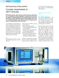
The following diagram shows the position of the intermodulation products in the frequency<br />
domain.<br />
Level<br />
Fig. 2.1 3 rd order intermodulation products<br />
Example<br />
Pu1<br />
Pu2<br />
Ps1 Ps2<br />
∆f<br />
∆f ∆f<br />
fs1 fu1 fu2 fs2<br />
fu1 = 100 MHz, fu2 = 100.03 MHz<br />
Frequency<br />
fs1 = 2 × fu1 – fu2 = 2 × 100 MHz – 100.03 MHz = 99.97 MHz<br />
fs2 = 2 × fu2 – fu1 = 2 × 100.03 MHz – 100 MHz = 100.06 MHz<br />
The level of the intermodulation products depends on the level of the useful signals.<br />
If the level of the two useful signals is increased by 1 dB, the level of the intermodulation<br />
products is increased by 3 dB. The intermodulation distance d3 is, therefore,<br />
reduced by 2 dB. Fig. 2.2 shows how the levels of the useful signals and the 3 rd<br />
order intermodulation products are related.<br />
Operating Manual 1313.9681.12 - 01 2.3<br />
aD3<br />
(6)<br />
(7)
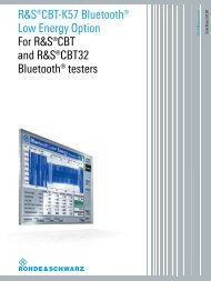
R&S <strong>FSQ</strong> Getting Started<br />
Output<br />
level<br />
1<br />
Carrier<br />
level<br />
1<br />
Intercept<br />
point<br />
Compression<br />
aD3<br />
Measuring the Spectrums of Complex <strong>Signal</strong>s<br />
Intermodulation<br />
products<br />
Input level<br />
Fig. 2.2 Level of the 3 rd order intermodulation products as a function of the level of the useful<br />
signals<br />
The behavior of the signals can explained using an amplifier as an example. The<br />
change in the level of the useful signals at the output of the amplifier is proportional<br />
to the level change at the input of the amplifier as long as the amplifier is operating<br />
in linear range. If the level at the amplifier input is changed by 1 dB, there is a 1 dB<br />
level change at the amplifier output. At a certain input level, the amplifier enters saturation.<br />
The level at the amplifier output does not increase with increasing input<br />
level.<br />
The level of the 3 rd order intermodulation products increases 3 times faster than the<br />
level of the useful signals. The 3 rd order intercept is the virtual level at which the<br />
level of the useful signals and the level of the spurious products are identical, i.e. the<br />
intersection of the two straight lines. This level cannot be measured directly as the<br />
amplifier goes into saturation or is damaged before this level is reached.<br />
The 3 rd order intercept can be calculated from the known slopes of the lines, the<br />
intermodulation distance d2 and the level of the useful signals.<br />
TOI = aD3 / 2 + Pn<br />
(8)<br />
with TOI (Third Order Intercept) being the 3rd order intercept in dBm and Pn the<br />
level of a carrier in dBm.<br />
With an intermodulation distance of 60 dB and an input level, Pw, of –20 dBm, the<br />
following 3rd order intercept is obtained:<br />
TOI = 60 dBm / 2 + (-20 dBm) = 10 dBm.<br />
2.4 Operating Manual 1313.9681.12 - 01<br />
1<br />
3
R&S <strong>FSQ</strong> Getting Started<br />
Measuring the Spectrums of Complex <strong>Signal</strong>s<br />
2.2.1.1 Measurement Example – Measuring the R&S <strong>FSQ</strong>’s Intrinsic Intermodulation<br />
Distance<br />
To measure the intrinsic intermodulation distance, use the test setup shown in the<br />
figure below.<br />
Test setup<br />
<strong>Signal</strong> generator settings (e.g. R&S SMIQ)<br />
Measurement using the R&S <strong>FSQ</strong><br />
1. Set the R&S <strong>FSQ</strong> to the analyzer mode.<br />
➢ Press the SPECTRUM key.<br />
The R&S <strong>FSQ</strong> is in the analyzer mode.<br />
2. Set center frequency to 1 GHz and the frequency span to 1 MHz.<br />
➢ Press the FREQ key and enter 1 GHz.<br />
➢ Press the SPAN key and enter 1 MHz.<br />
3. Set the reference level to –10 dBm and RF attenuation to 0 dB.<br />
➢ Press the AMPT key and enter -10 dBm.<br />
➢ Press the RF ATTEN MANUAL softkey and enter 0 dB.<br />
By reducing the RF attenuation to 0 dB, the level to the R&S <strong>FSQ</strong> input mixer<br />
is increased. Therefore, 3 rd order intermodulation products are displayed.<br />
4. Set the resolution bandwidth to 5 kHz.<br />
➢ Press the BW key.<br />
Level Frequency<br />
<strong>Signal</strong> generator 1 -10 dBm 999.9 MHz<br />
<strong>Signal</strong> generator 2 -10 dBm 1000.1 MHz<br />
➢ Press the RES BW MANUAL softkey and enter 5 kHz.<br />
By reducing the bandwidth, the noise is further reduced and the<br />
intermodulation products can be clearly seen.<br />
5. Measuring intermodulation by means of the 3rd order intercept<br />
measurement function.<br />
➢ Press the MEAS key.<br />
Operating Manual 1313.9681.12 - 01 2.5
R&S <strong>FSQ</strong> Getting Started<br />
➢ Press the TOI softkey.<br />
Measuring the Spectrums of Complex <strong>Signal</strong>s<br />
The R&S <strong>FSQ</strong> activates four markers for measuring the intermodulation<br />
distance. Two markers are positioned on the useful signals and two on the<br />
intermodulation products. The 3rd order intercept is calculated from the level<br />
difference between the useful signals and the intermodulation products. It is<br />
then displayed on the screen:<br />
Fig. 2.3 Result of intrinsic intermodulation measurement on the R&S <strong>FSQ</strong>. The 3rd order<br />
intercept (TOI) is displayed at the top right corner of the grid<br />
The level of a <strong>Signal</strong> <strong>Analyzer</strong>’s intrinsic intermodulation products depends on<br />
the RF level of the useful signals at the input mixer. When the RF attenuation<br />
is added, the mixer level is reduced and the intermodulation distance is<br />
increased. With an additional RF attenuation of 10 dB, the levels of the<br />
intermodulation products are reduced by 20 dB. The noise level is, however,<br />
increased by 10 dB.<br />
6. Increasing RF attenuation to 10 dB to reduce intermodulation products.<br />
➢ Press the AMPT key.<br />
➢ Press the RF ATTEN MANUAL softkey and enter 10 dB.<br />
The R&S <strong>FSQ</strong>’s intrinsic intermodulation products disappear below the noise<br />
floor.<br />
2.6 Operating Manual 1313.9681.12 - 01
R&S <strong>FSQ</strong> Getting Started<br />
Measuring the Spectrums of Complex <strong>Signal</strong>s<br />
Fig. 2.4 If the RF attenuation is increased, the R&S <strong>FSQ</strong>’s intrinsic intermodulation products<br />
disappear below the noise floor.<br />
Calculation method<br />
The method used by the R&S <strong>FSQ</strong> to calculate the intercept point takes the average<br />
useful signal level PU in dBm and calculates the intermodulation d3 in dB as a function<br />
of the average value of the levels of the two intermodulation products. The third<br />
order intercept (TOI) is then calculated as follows:<br />
TOI/dBm = ½ d3 + PU<br />
Intermodulation- free dynamic range<br />
The Intermodulation – free dynamic range, i.e. the level range in which no internal<br />
intermodulation products are generated if two-tone signals are measured, is<br />
determined by the 3rd order intercept point, the phase noise and the thermal noise of<br />
the R&S <strong>FSQ</strong>. At high signal levels, the range is determined by intermodulation<br />
products. At low signal levels, intermodulation products disappear below the noise<br />
floor, i.e. the noise floor and the phase noise of the R&S <strong>FSQ</strong> determine the range.<br />
The noise floor and the phase noise depend on the resolution bandwidth that has<br />
been selected. At the smallest resolution bandwidth, the noise floor and phase noise<br />
are at a minimum and so the maximum range is obtained. However, a large increase<br />
in sweep time is required for small resolution bandwidths. It is, therefore, best to<br />
select the largest resolution bandwidth possible to obtain the range that is required.<br />
Since phase noise decreases as the carrier-offset increases, its influence decreases<br />
with increasing frequency offset from the useful signals.<br />
Operating Manual 1313.9681.12 - 01 2.7
R&S <strong>FSQ</strong> Getting Started<br />
Measuring the Spectrums of Complex <strong>Signal</strong>s<br />
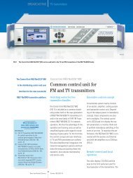
The following diagrams illustrate the intermodulation-free dynamic range as a function<br />
of the selected bandwidth and of the level at the input mixer (= signal level – set<br />
RF attenuation) at different useful signal offsets.<br />
Dynamic range dB<br />
-60<br />
-70<br />
-80<br />
-90<br />
-100<br />
-110<br />
-120<br />
Distortion free dynamic range<br />
1MHz carrier offset<br />
RBW=10 kHz<br />
RBW=1<br />
kHz<br />
RBW=100<br />
Hz<br />
RBW=10<br />
Hz<br />
-60 -50 -40 -30 -20 -10<br />
Mixer level<br />
Fig. 2.5 Intermodulation-free range of the R&S <strong>FSQ</strong> as a function of level at the input mixer and<br />
the set resolution bandwidth (useful signal offset = 1 MHz, DANL = -157 dBm /Hz, TOI =<br />
25 dBm; typical values at 2 GHz)<br />
The optimum mixer level, i.e. the level at which the intermodulation distance is at its<br />
maximum, depends on the bandwidth. At a resolution bandwidth of 10 Hz, it is<br />
approx. –42 dBm and at 10 kHz increases to approx. -32 dBm.<br />
Phase noise has a considerable influence on the intermodulation-free range at carrier<br />
offsets between 10 and 100 kHz (Fig. 2.6). At greater bandwidths, the influence<br />
of the phase noise is greater than it would be with small bandwidths. The optimum<br />
mixer level at the bandwidths under consideration becomes almost independent of<br />
bandwidth and is approx. –40 dBm.<br />
Dynamic range dB<br />
-60<br />
-70<br />
-80<br />
-90<br />
-100<br />
-110<br />
Distortion free dynamic range<br />
10 to 100 kHz offset<br />
RBW=10 kHz<br />
RBW=1<br />
kHz<br />
RBW=100<br />
Hz<br />
RBW=10<br />
Hz<br />
Fig. 2.6 Intermodulation-free dynamic range of the R&S <strong>FSQ</strong> as a function of level at the input<br />
mixer and of the selected resolution bandwidth (useful signal offset = 10 to 100 kHz,<br />
DANL = -157 dBm /Hz, TOI = 25 dBm; typical values at 2 GHz).<br />
2.8 Operating Manual 1313.9681.12 - 01<br />
T.O.I<br />
Thermal noise<br />
-120<br />
-60 -50 -40 -30 -20 -10<br />
Mixer level<br />
Thermal noise<br />
T.O.I
R&S <strong>FSQ</strong> Getting Started<br />
Measuring <strong>Signal</strong>s in the Vicinity of Noise<br />
If the intermodulation products of a DUT with a very high dynamic range are to be<br />
measured and the resolution bandwidth to be used is therefore very small, it is<br />
best to measure the levels of the useful signals and those of the intermodulation<br />
products separately using a small span. The measurement time will be reduced–<br />
in particular if the offset of the useful signals is large. To find signals reliably when<br />
frequency span is small, it is best to synchronize the signal sources and the<br />
R&S <strong>FSQ</strong>.<br />
2.3 Measuring <strong>Signal</strong>s in the Vicinity of Noise<br />
The minimum signal level a <strong>Signal</strong> <strong>Analyzer</strong> can measure is limited by its intrinsic<br />
noise. Small signals can be swamped by noise and therefore cannot be measured.<br />
For signals that are just above the intrinsic noise, the accuracy of the level measurement<br />
is influenced by the intrinsic noise of the R&S <strong>FSQ</strong>.<br />
The displayed noise level of a <strong>Signal</strong> <strong>Analyzer</strong> depends on its noise figure, the<br />
selected RF attenuation, the selected reference level, the selected resolution and<br />
video bandwidth and the detector. The effect of the different parameters is explained<br />
in the following.<br />
Impact of the RF attenuation setting<br />
The sensitivity of a <strong>Signal</strong> <strong>Analyzer</strong> is directly influenced by the selected RF attenuation.<br />
The highest sensitivity is obtained at a RF attenuation of 0 dB. The<br />
R&S <strong>FSQ</strong>’s RF attenuation can be set in 5 dB steps up to 70 dB. Each additional 5<br />
dB step reduces the R&S <strong>FSQ</strong>’s sensitivity by 5 dB, i.e. the displayed noise is<br />
increased by 5 dB.<br />
Impact of the reference level setting<br />
If the reference level is changed, the R&S <strong>FSQ</strong> changes the gain on the last IF so<br />
that the voltage at the logarithmic amplifier and the A/D converter is always the<br />
same for signal levels corresponding to the reference level. This ensures that the<br />
dynamic range of the log amp or the A/D converter is fully utilized. Therefore, the<br />
total gain of the signal path is low at high reference levels and the noise figure of the<br />
IF amplifier makes a substantial contribution to the total noise figure of the<br />
R&S <strong>FSQ</strong>. The figure below shows the change in the displayed noise depending on<br />
the set reference level at 10 kHz and 300 kHz resolution bandwidth. With digital<br />
bandwidths (≤100 kHz) the noise increases sharply at high reference levels because<br />
of the dynamic range of the A/D converter.<br />
Operating Manual 1313.9681.12 - 01 2.9
R&S <strong>FSQ</strong> Getting Started<br />
rel. noise level /dB<br />
14<br />
12<br />
10<br />
8<br />
6<br />
4<br />
2<br />
0<br />
-2<br />
Measuring <strong>Signal</strong>s in the Vicinity of Noise<br />
-70 -60 -50 -40 -30 -20 -10<br />
Reference level /dBm<br />
Fig. 2.7 Change in displayed noise as a function of the selected reference level at bandwidths of<br />
10 kHz and 300 kHz (-30 dBm reference level)<br />
Impact of the resolution bandwidth<br />
The sensitivity of a <strong>Signal</strong> <strong>Analyzer</strong> also directly depends on the selected bandwidth.<br />
The highest sensitivity is obtained at the smallest bandwidth (for the R&S <strong>FSQ</strong>: 10<br />
Hz, for FFT filtering: 1 Hz). If the bandwidth is increased, the reduction in sensitivity<br />
is proportional to the change in bandwidth. The R&S <strong>FSQ</strong> has bandwidth settings in<br />
2, 3, 5, 10 sequence. Increasing the bandwidth by a factor of 3 increases the displayed<br />
noise by approx. 5 dB (4.77 dB precisely). If the bandwidth is increased by a<br />
factor of 10, the displayed noise increases by a factor of 10, i.e. 10 dB. Because of<br />
the way the resolution filters are designed, the sensitivity of <strong>Signal</strong> <strong>Analyzer</strong>s often<br />
depends on the selected resolution bandwidth. In data sheets, the displayed average<br />
noise level is often indicated for the smallest available bandwidth. The extra<br />
sensitivity obtained if the bandwidth is reduced may therefore deviate from the values<br />
indicated above. The following table illustrates typical deviations from the noise<br />
figure for a resolution bandwidth of 10 kHz which is used as a reference value (= 0<br />
dB).<br />
Noise figure<br />
offset /dB<br />
3<br />
2<br />
1<br />
0<br />
-1<br />
RBW = 10 kHz<br />
RBW = 300 kHz<br />
digital RBW analog RBW<br />
0,01 0,1 1 10 100 1000 10000<br />
RBW /kHz<br />
Fig. 2.8 Change in R&S <strong>FSQ</strong> noise figure at various bandwidths. The reference bandwidth is 10<br />
kHz<br />
2.10 Operating Manual 1313.9681.12 - 01
R&S <strong>FSQ</strong> Getting Started<br />
Impact of the video bandwidth<br />
Measuring <strong>Signal</strong>s in the Vicinity of Noise<br />
The displayed noise of a <strong>Signal</strong> <strong>Analyzer</strong> is also influenced by the selected video<br />
bandwidth. If the video bandwidth is considerably smaller than the resolution bandwidth,<br />
noise spikes are suppressed, i.e. the trace becomes much smoother. The<br />
level of a sinewave signal is not influenced by the video bandwidth. A sinewave signal<br />
can therefore be freed from noise by using a video bandwidth that is small compared<br />
with the resolution bandwidth, and thus be measured more accurately.<br />
Impact of the detector<br />
Noise is evaluated differently by the different detectors. The noise display is therefore<br />
influenced by the choice of detector. Sinewave signals are weighted in the<br />
same way by all detectors, i.e. the level display for a sinewave RF signal does not<br />
depend on the selected detector, provided that the signal-to-noise ratio is high<br />
enough. The measurement accuracy for signals in the vicinity of R&S <strong>FSQ</strong> intrinsic<br />
noise is also influenced by the detector which has been selected. The R&S <strong>FSQ</strong> has<br />
the following detectors:<br />
• Maximum peak detector<br />
If the max. peak detector s selected, the largest noise display is obtained, since<br />
the R&S <strong>FSQ</strong> displays the highest value of the IF envelope in the frequency range<br />
assigned to a pixel at each pixel in the trace. With longer sweep times, the trace<br />
indicates higher noise levels since the probability of obtaining a high noise<br />
amplitude increases with the dwell time on a pixel. For short sweep times, the<br />
display approaches that of the sample detector since the dwell time on a pixel is<br />
only sufficient to obtain an instantaneous value.<br />
• Minimum peak detector<br />
The min. peak detector indicates the minimum voltage of the IF envelope in the<br />
frequency range assigned to a pixel at each pixel in the trace. The noise is strongly<br />
suppressed by the minimum peak detector since the lowest noise amplitude that<br />
occurs is displayed for each test point. If the signal-to-noise ratio is low, the<br />
minimum of the noise overlaying the signal is displayed too low.<br />
At longer sweep times, the trace shows smaller noise levels since the probability<br />
of obtaining a low noise amplitude increases with the dwell time on a pixel. For<br />
short sweep times, the display approaches that of the sample detector since the<br />
dwell time on a pixel is only sufficient to obtain an instantaneous value.<br />
• Autopeak detector<br />
The Autopeak detector displays the maximum and minimum peak value at the<br />
same time. Both values are measured and their levels are displayed on the screen<br />
joint by a vertical line.<br />
• Sample detector<br />
The sample detector samples the logarithm of the IF envelope for each pixel of<br />
the trace only once and displays the resulting value. If the frequency span of the<br />
R&S <strong>FSQ</strong> is considerably higher than the resolution bandwidth (span/RBW >500),<br />
there is no guarantee that useful signals will be detected. They are lost due to<br />
undersampling. This does not happen with noise because in this case it is not the<br />
instantaneous amplitude that is relevant but only the probability distribution.<br />
Operating Manual 1313.9681.12 - 01 2.11
R&S <strong>FSQ</strong> Getting Started<br />
• RMS detector<br />
Measuring <strong>Signal</strong>s in the Vicinity of Noise<br />
For each pixel of the trace, the RMS detector outputs the RMS value of the IF<br />
envelope for the frequency range assigned to each test point. It therefore<br />
measures noise power. The display for small signals is, however, the sum of<br />
signal power and noise power. For short sweep times, i.e. if only one uncorrelated<br />
sample value contributes to the RMS value measurement, the RMS detector is<br />
equivalent to the sample detector. If the sweep time is longer, more and more<br />
uncorrelated RMS values contribute to the RMS value measurement. The trace<br />
is, therefore, smoothed. The level of sinewave signals is only displayed correctly<br />
if the selected resolution bandwidth (RBW) is at least as wide as the frequency<br />
range which corresponds to a pixel in the trace. At a resolution bandwidth of 1<br />
MHz, this means that the maximum frequency display range is 625 MHz.<br />
• Average detector<br />
For each pixel of the trace, the average detector outputs the average value of the<br />
linear IF envelope for the frequency range assigned to each test point. It therefore<br />
measures the linear average noise. The level of sinewave signals is only<br />
displayed correctly if the selected resolution bandwidth (RBW) is at least as wide<br />
as the frequency range which corresponds to a pixel in the trace. At a resolution<br />
bandwidth of 1 MHz, this means the maximum frequency display range is 625<br />
MHz.<br />
• Quasipeak detector<br />
The quasipeak detector is a peak detector for EMI measurements with defined<br />
charge and discharge times. These times are defined in CISPR 16, the standard<br />
for equipment used to measure EMI emissions.<br />
2.3.0.1 Measurement Example – Measuring the Level of the Internal Reference Generator<br />
at Low S/N Ratios<br />
The example shows the different factors influencing the S/N ratio.<br />
1. Set the R&S <strong>FSQ</strong> to the analyzer mode.<br />
➢ Press the SPECTRUM key.<br />
The R&S <strong>FSQ</strong> is in the analyzer mode.<br />
2. Switch on the internal reference generator<br />
➢ Press the SETUP key.<br />
➢ Press the softkeys SERVICE - INPUT CAL.<br />
The internal 128 MHz reference generator is on.<br />
The R&S <strong>FSQ</strong>’s RF input is off.<br />
3. Set the center frequency to 128 MHz and the frequency span to 100 MHz.<br />
➢ Press the FREQ key and enter 128 MHz.<br />
➢ Press the SPAN key and enter 100 MHz.<br />
4. Set the RF attenuation to 60 dB to attenuate the input signal or to increase<br />
the intrinsic noise.<br />
➢ Press the AMPT key.<br />
2.12 Operating Manual 1313.9681.12 - 01
R&S <strong>FSQ</strong> Getting Started<br />
Measuring <strong>Signal</strong>s in the Vicinity of Noise<br />
➢ Press the RF ATTEN MANUAL softkey and enter 60 dB.<br />
The RF attenuation indicator is marked with an asterisk (*Att 60 dB) to show<br />
that it is no longer coupled to the reference level. The high input attenuation<br />
reduces the reference signal which can no longer be detected in noise.<br />
Fig. 2.9 Sinewave signal with low S/N ratio. The signal is measured with the autopeak<br />
detector and is completely swamped by the intrinsic noise of the R&S <strong>FSQ</strong>.<br />
5. To suppress noise spikes the trace can be averaged.<br />
➢ Press the TRACE key.<br />
➢ Press the AVERAGE softkey.<br />
The traces of consecutive sweeps are averaged. To perform averaging, the<br />
R&S <strong>FSQ</strong> automatically switches on the sample detector. The RF signal,<br />
therefore, can be more clearly distinguished from noise.<br />
Operating Manual 1313.9681.12 - 01 2.13
R&S <strong>FSQ</strong> Getting Started<br />
Measuring <strong>Signal</strong>s in the Vicinity of Noise<br />
Fig. 2.10 RF sinewave signal with low S/N ratio if the trace is averaged.<br />
6. Instead of trace averaging, a video filter that is narrower than the resolution<br />
bandwidth can be selected.<br />
➢ Press the CLEAR/WRITE softkey in the trace menu.<br />
➢ Press the BW key.<br />
Press the VIDEO BW MANUAL softkey and enter 10 kHz.<br />
The RF signal can be more clearly distinguished from noise.<br />
2.14 Operating Manual 1313.9681.12 - 01
R&S <strong>FSQ</strong> Getting Started<br />
Measuring <strong>Signal</strong>s in the Vicinity of Noise<br />
Fig. 2.11 RF sinewave signal with low S/N ratio if a smaller video bandwidth is selected.<br />
7. By reducing the resolution bandwidth by a factor of 10, the noise is reduced<br />
by 10 dB.<br />
➢ Press the RES BW MANUAL softkey and enter 300 kHz.<br />
The displayed noise is reduced by approx. 10 dB. The signal, therefore,<br />
emerges from noise by about 10 dB. Compared to the previous setting, the<br />
video bandwidth has remained the same, i.e. it has increased relative to the<br />
smaller resolution bandwidth. The averaging effect is, therefore, reduced by<br />
the video bandwidth. The trace will be noisier.<br />
Operating Manual 1313.9681.12 - 01 2.15
R&S <strong>FSQ</strong> Getting Started<br />
Fig. 2.12 Reference signal at a smaller resolution bandwidth<br />
Measuring <strong>Signal</strong>s in the Vicinity of Noise<br />
2.16 Operating Manual 1313.9681.12 - 01
R&S <strong>FSQ</strong> Getting Started<br />
2.4 Noise Measurements<br />
Noise Measurements<br />
Noise measurements play an important role in spectrum analysis. Noise e.g. affects<br />
the sensitivity of radio communication systems and their components.<br />
Noise power is specified either as the total power in the transmission channel or as<br />
the power referred to a bandwidth of 1 Hz. The sources of noise are, for example,<br />
amplifier noise or noise generated by oscillators used for the frequency conversion<br />
of useful signals in receivers or transmitters. The noise at the output of an amplifier<br />
is determined by its noise figure and gain.<br />
The noise of an oscillator is determined by phase noise near the oscillator frequency<br />
and by thermal noise of the active elements far from the oscillator frequency. Phase<br />
noise can mask weak signals near the oscillator frequency and make them impossible<br />
to detect.<br />
2.4.1 Measuring Noise Power Density<br />
To measure noise power referred to a bandwidth of 1 Hz at a certain frequency, the<br />
R&S <strong>FSQ</strong> has an easy-to-use marker function. This marker function calculates the<br />
noise power density from the measured marker level.<br />
2.4.1.1 Measurement Example – Measuring the Intrinsic Noise Power Density of the<br />
R&S <strong>FSQ</strong> at 1 GHz and Calculating the R&S <strong>FSQ</strong>’s Noise Figure<br />
1. Set the R&S <strong>FSQ</strong> to the analyzer mode.<br />
➢ Press the SPECTRUM key.<br />
The R&S <strong>FSQ</strong> is in the analyzer mode.<br />
2. Set the center frequency to 1 GHz and the span to 1 MHz.<br />
➢ Press the FREQ key and enter 1 GHz.<br />
➢ Press the SPAN key and enter 1 MHz.<br />
3. Switch on the marker and set the marker frequency to 1 GHz.<br />
➢ Press the MKR key and enter 1 GHz.<br />
4. Switch on the noise marker function.<br />
➢ Press the MEAS key.<br />
➢ Press the NOISE MARKER softkey.<br />
The R&S <strong>FSQ</strong> displays the noise power at 1 GHz in dBm (1Hz).<br />
Since noise is random, a sufficiently long measurement time has to be selected<br />
to obtain stable measurement results. This can be achieved by averaging the<br />
trace or by selecting a very small video bandwidth relative to the resolution<br />
bandwidth.<br />
5. The measurement result is stabilized by averaging the trace<br />
➢ Press the TRACE key.<br />
➢ Press the AVERAGE softkey.<br />
The R&S <strong>FSQ</strong> performs sliding averaging over 10 traces from consecutive<br />
sweeps. The measurement result becomes more stable.<br />
Operating Manual 1313.9681.12 - 01 2.17
R&S <strong>FSQ</strong> Getting Started<br />
Conversion to other reference bandwidths<br />
Noise Measurements<br />
The result of the noise measurement can be referred to other bandwidths by simple<br />
conversion. This is done by adding 10 · log (BW) to the measurement result, BW<br />
being the new reference bandwidth.<br />
Example<br />
A noise power of –150 dBm (1 Hz) is to be referred to a bandwidth of 1 kHz.<br />
P[1kHz] = -150 + 10 · log (1000) = -150 +30 = -120 dBm(1 kHz)<br />
Calculation method<br />
The following method is used to calculate the noise power:<br />
If the noise marker is switched on, the R&S <strong>FSQ</strong> automatically activates the sample<br />
detector. The video bandwidth is set to 1/10 of the selected resolution bandwidth<br />
(RBW).<br />
To calculate the noise, the R&S <strong>FSQ</strong> takes an average over 17 adjacent pixels (the<br />
pixel on which the marker is positioned and 8 pixels to the left, 8 pixels to the right of<br />
the marker). The measurement result is stabilized by video filtering and averaging<br />
over 17 pixels.<br />
Since both video filtering and averaging over 17 trace points is performed in the log<br />
display mode, the result would be 2.51 dB too low (difference between logarithmic<br />
noise average and noise power). The R&S <strong>FSQ</strong>, therefore, corrects the noise figure<br />
by 2.51 dB.<br />
To standardize the measurement result to a bandwidth of 1 Hz, the result is also corrected<br />
by –10 · log (RBWnoise), with RBWnoise being the power bandwidth of the<br />
selected resolution filter (RBW).<br />
Detector selection<br />
The noise power density is measured in the default setting with the sample detector<br />
and using averaging. Other detectors that can be used to perform a measurement<br />
giving true results are the average detector or the RMS detector. If the average<br />
detector is used, the linear video voltage is averaged and displayed as a pixel. If the<br />
RMS detector is used, the squared video voltage is averaged and displayed as a<br />
pixel. The averaging time depends on the selected sweep time (=SWT/625). An<br />
increase in the sweep time gives a longer averaging time per pixel and thus stabilizes<br />
the measurement result. The R&S <strong>FSQ</strong> automatically corrects the measurement<br />
result of the noise marker display depending on the selected detector (+1.05<br />
dB for the average detector, 0 dΒ for the RMS detector). It is assumed that the video<br />
bandwidth is set to at least three times the resolution bandwidth. While the average<br />
or RMS detector is being switched on, the R&S <strong>FSQ</strong> sets the video bandwidth to a<br />
suitable value.<br />
The Pos Peak, Neg Peak, Auto Peak and Quasipeak detectors are not suitable for<br />
measuring noise power density.<br />
2.18 Operating Manual 1313.9681.12 - 01
R&S <strong>FSQ</strong> Getting Started<br />
Determining the noise figure<br />
Noise Measurements<br />
The noise figure of amplifiers or of the R&S <strong>FSQ</strong> alone can be obtained from the<br />
noise power display. Based on the known thermal noise power of a 50 Ω resistor at<br />
room temperature (-174 dBm (1Hz)) and the measured noise power Pnoise the noise<br />
figure (NF) is obtained as follows:<br />
NF = Pnoise + 174 – g,<br />
where g = gain of DUT in dB<br />
Example:<br />
The measured internal noise power of the R&S <strong>FSQ</strong> at an attenuation of 0 dB is<br />
found to be –155 dBm/1 Hz. The noise figure of the R&S <strong>FSQ</strong> is obtained as follows<br />
NF = –155 + 174 = 17 dB<br />
If noise power is measured at the output of an amplifier, for example, the sum of<br />
the internal noise power and the noise power at the output of the DUT is measured.<br />
The noise power of the DUT can be obtained by subtracting the internal<br />
noise power from the total power (subtraction of linear noise powers). By means<br />
of the following diagram, the noise level of the DUT can be estimated from the<br />
level difference between the total and the internal noise level.<br />
Correction factor in dB<br />
Total power/intrinsic noise power in dB<br />
Fig. 2.13 Correction factor for measured noise power as a function of the ratio of total power to<br />
the intrinsic noise power of the R&S <strong>FSQ</strong>.<br />
Operating Manual 1313.9681.12 - 01 2.19
R&S <strong>FSQ</strong> Getting Started<br />
Noise Measurements<br />
2.4.2 Measurement of Noise Power within a Transmission Channel<br />
Noise in any bandwidth can be measured with the channel power measurement<br />
functions. Thus the noise power in a communication channel can be determined, for<br />
example. If the noise spectrum within the channel bandwidth is flat, the noise marker<br />
from “Measuring Noise Power Density” on page 2.17 can be used to determine the<br />
noise power in the channel by considering the channel bandwidth. If, however,<br />
phase noise and noise that normally increases towards the carrier is dominant in the<br />
channel to be measured, or if there are discrete spurious signals in the channel, the<br />
channel power measurement method must be used to obtain correct measurement<br />
results.<br />
2.4.2.1 Measurement Example – Measuring the Intrinsic Noise of the R&S <strong>FSQ</strong> at<br />
1 GHz in a 1.23 MHz Channel Bandwidth with the Channel Power Function<br />
Test setup<br />
The RF input of the R&S <strong>FSQ</strong> remains open-circuited or is terminated with 50 Ω.<br />
Measurement with the R&S <strong>FSQ</strong><br />
1. Set the R&S <strong>FSQ</strong> to the analyzer mode.<br />
➢ Press the SPECTRUM key.<br />
The R&S <strong>FSQ</strong> is in the analyzer mode.<br />
2. Set the center frequency to 1 GHz and the span to 2 MHz.<br />
➢ Press the FREQ key and enter 1 GHz.<br />
➢ Press the SPAN key and enter 2 MHz.<br />
3. To obtain maximum sensitivity, set RF attenuation on the R&S <strong>FSQ</strong> to 0 dB.<br />
➢ Press the AMPT key.<br />
➢ Press the RF ATTEN MANUAL softkey and enter 0 dB.<br />
4. Switch on and configure the channel power measurement.<br />
➢ Press the MEAS key.<br />
➢ Press the CHAN PWR ACP softkey.<br />
The R&S <strong>FSQ</strong> activates the channel or adjacent channel power measurement<br />
according to the currently set configuration.<br />
➢ Press the CP/ACP CONFIG � softkey.<br />
The R&S <strong>FSQ</strong> enters the submenu for configuring the channel.<br />
➢ Press the CHANNEL BANDWIDTH softkey and enter 1.23 MHz.<br />
The R&S <strong>FSQ</strong> displays the 1.23 MHz channel as two vertical lines which are<br />
symmetrical to the center frequency.<br />
➢ Press the PREV key.<br />
The R&S <strong>FSQ</strong> returns to the main menu for channel and adjacent channel<br />
power measurement.<br />
➢ Press the ADJUST SETTINGS softkey.<br />
The settings for the frequency span, the bandwidth (RBW and VBW) and the<br />
detector are automatically set to the optimum values required for the<br />
measurement.<br />
2.20 Operating Manual 1313.9681.12 - 01
R&S <strong>FSQ</strong> Getting Started<br />
Noise Measurements<br />
Fig. 2.14 Measurement of the R&S <strong>FSQ</strong>’s intrinsic noise power in a 1.23 MHz channel<br />
bandwidth.<br />
5. Stabilizing the measurement result by increasing the sweep time<br />
➢ Press the SWEEP TIME softkey and enter 1 s.<br />
By increasing the sweep time to 1 s, the trace becomes much smoother<br />
thanks to the RMS detector and the channel power measurement display is<br />
much more stable.<br />
6. Referring the measured channel power to a bandwidth of 1 Hz<br />
➢ Press the CHAN PWR / Hz softkey.<br />
The channel power is referred to a bandwidth of 1 Hz. The measurement is<br />
corrected by -10 · log (ChanBW), with ChanBW being the channel bandwidth<br />
that was selected.<br />
Method of calculating the channel power<br />
When measuring the channel power, the R&S <strong>FSQ</strong> integrates the linear power<br />
which corresponds to the levels of the pixels within the selected channel. The<br />
R&S <strong>FSQ</strong> uses a resolution bandwidth which is far smaller than the channel bandwidth.<br />
When sweeping over the channel, the channel filter is formed by the passband<br />
characteristics of the resolution bandwidth (see Fig. 2.15).<br />
Operating Manual 1313.9681.12 - 01 2.21
R&S <strong>FSQ</strong> Getting Started<br />
Noise Measurements<br />
Fig. 2.15 Approximating the channel filter by sweeping with a small resolution bandwidth<br />
The following steps are performed:<br />
• The linear power of all the trace pixels within the channel is calculated.<br />
Pi = 10(Li/10)<br />
where<br />
Pi = power of the trace pixel i<br />
Li = displayed level of trace point i<br />
• The powers of all trace pixels within the channel are summed up and the sum is<br />
divided by the number of trace pixels in the channel.<br />
• The result is multiplied by the quotient of the selected channel bandwidth and the<br />
noise bandwidth of the resolution filter (RBW).<br />
Since the power calculation is performed by integrating the trace within the channel<br />
bandwidth, this method is also called the IBW method (Integration Bandwidth<br />
method).<br />
Bandwidth selection (RBW)<br />
For channel power measurements, the resolution bandwidth (RBW) must be small<br />
compared to the channel bandwidth, so that the channel bandwidth can be defined<br />
precisely. If the resolution bandwidth which has been selected is too wide, this may<br />
have a negative effect on the selectivity of the simulated channel filter and result in<br />
the power in the adjacent channel being added to the power in the transmit channel.<br />
A resolution bandwidth equal to 1% to 3% of the channel bandwidth should, therefore,<br />
be selected. If the resolution bandwidth is too small, the required sweep time<br />
becomes too long and the measurement time increases considerably.<br />
Detector selection<br />
Resolution filter<br />
Sweep<br />
Channel bandwith<br />
Since the power of the trace is measured within the channel bandwidth, only the<br />
sample detector and RMS detector can be used. These detectors provide measured<br />
values that make it possible to calculate the real power. The peak detectors (Pos<br />
Peak, Neg Peak and Auto Peak) are not suitable for noise power measurements as<br />
no correlation can be established between the peak value of the video voltage and<br />
power.<br />
With the sample detector, a value (sample) of the IF envelope voltage is displayed<br />
at each trace pixel. Since the frequency spans are very large compared with the resolution<br />
bandwidth (span/RBW >500), sinewave signals present in the noise might be<br />
2.22 Operating Manual 1313.9681.12 - 01<br />
-3 dB
R&S <strong>FSQ</strong> Getting Started<br />
Noise Measurements<br />
lost, i.e. they are not displayed. This is not important for pure noise signals, however,<br />
since a single sample in itself is not important - it is the probability distribution of all<br />
measured values that counts. The number of samples for power calculation is limited<br />
to the number of trace pixels (625 for the R&S <strong>FSQ</strong>).<br />
To increase the repeatability of measurements, averaging is often carried out<br />
over several traces (AVERAGE softkey in the TRACE menu). This gives spurious<br />
results for channel power measurements (max. –2.51 dB for ideal averaging).<br />
Trace averaging should, therefore, be avoided.<br />
With the RMS detector, the whole IF envelope is used to calculate the power for<br />
each trace pixel. The IF envelope is digitized using a sampling frequency which is at<br />
least five times the resolution bandwidth which has been selected. Based on the<br />
sample values, the power is calculated for each trace pixel using the following formula:<br />
P RMS<br />
=<br />
1 2<br />
--- × s<br />
N ∑ i<br />
i = 1<br />
si = linear digitized video voltage at the output of the A/D converter<br />
N = number of A/D converter values per pixel of the trace<br />
PRMS = power represented by a trace pixel<br />
When the power has been calculated, the power units are converted into decibels<br />
and the value is displayed as a trace pixel.<br />
The number of A/D converter values, N, used to calculate the power, is defined by<br />
the sweep time. The time per trace pixel for power measurements is directly proportional<br />
to the selected sweep time. The RMS detector uses far more samples for<br />
power measurement than the sample detector, especially if the sweep time is<br />
increased. The measurement uncertainty can be reduced considerably. In the<br />
default setting, the R&S <strong>FSQ</strong> therefore uses the RMS detector to measure the channel<br />
power.<br />
For both detectors (sample and RMS), the video bandwidth (VBW) must at least be<br />
three times the resolution bandwidth, so that the peak values of the video voltage<br />
are not cut off by the video filter. At smaller video bandwidths, the video signal is<br />
averaged and the power readout will be too small.<br />
Sweep time selection<br />
N<br />
If the sample detector is used, it is best to select the smallest sweep time possible<br />
for a given span and resolution bandwidth. The minimum time is obtained if the setting<br />
is coupled. This means that the time per measurement is minimal. Extending<br />
the measurement time does not have any advantages as the number of samples for<br />
calculating the power is defined by the number of trace pixels in the channel.<br />
When using the RMS detector, the repeatability of the measurement results can be<br />
influenced by the selection of sweep times. Repeatability is increased at longer<br />
sweep times.<br />
Operating Manual 1313.9681.12 - 01 2.23
R&S <strong>FSQ</strong> Getting Started<br />
Repeatability can be estimated from the following diagram:<br />
max. error/dB<br />
0<br />
0.5<br />
1<br />
1.5<br />
2<br />
2.5<br />
3<br />
Noise Measurements<br />
10 100 1000<br />
10000 100000<br />
Number of samples<br />
Fig. 2.16 Repeatability of channel power measurements as a function of the number of samples<br />
used for power calculation<br />
The curves in Fig. 2.16 indicates the repeatability obtained with a probability of 95%<br />
and 99% depending on the number of samples used.<br />
The repeatability with 600 samples is ± 0.5 dB. This means that – if the sample<br />
detector and a channel bandwidth over the whole diagram (channel bandwidth =<br />
span) is used - the measured value lies within ± 0.5 dB of the true value with a probability<br />
of 99%.<br />
If the RMS detector is used, the number of samples can be estimated as follows:<br />
Since only uncorrelated samples contribute to the RMS value, the number of samples<br />
can be calculated from the sweep time and the resolution bandwidth.<br />
Samples can be assumed to be uncorrelated if sampling is performed at intervals of<br />
1/RBW. The number of uncorrelated samples (Ndecorr) is calculated as follows:<br />
Ndecorr = SWT × RBW<br />
The number of uncorrelated samples per trace pixel is obtained by dividing Ndecorr<br />
by 625 (= pixels per trace).<br />
Example<br />
95 % Confidence<br />
level<br />
99 % Confidence<br />
level<br />
At a resolution bandwidth of 30 kHz and a sweep time of 100 ms, 3000 uncorrelated<br />
samples are obtained. If the channel bandwidth is equal to the frequency display<br />
range, i.e. all trace pixels are used for the channel power measurement, a repeatability<br />
of 0.2 dB with a confidence level of 99% is the estimate that can be derived<br />
from Fig. 2.16.<br />
2.24 Operating Manual 1313.9681.12 - 01
R&S <strong>FSQ</strong> Getting Started<br />
2.4.3 Measuring Phase Noise<br />
Noise Measurements<br />
The R&S <strong>FSQ</strong> has an easy-to-use marker function for phase noise measurements.<br />
This marker function indicates the phase noise of an RF oscillator at any carrier in<br />
dBc in a bandwidth of 1 Hz.<br />
2.4.3.1 Measurement Example – Measuring the Phase Noise of a <strong>Signal</strong> Generator at a<br />
Carrier Offset of 10 kHz<br />
Test setup<br />
Settings on the signal generator (e.g. R&S SMIQ)<br />
Frequency: 100 MHz<br />
Level: 0 dBm<br />
Measurement using R&S <strong>FSQ</strong><br />
1. Set the R&S <strong>FSQ</strong> to the analyzer mode<br />
➢ Press the SPECTRUM key.<br />
R&S <strong>FSQ</strong> is in the analyzer mode.<br />
2. Set the center frequency to 100 MHz and the span to 50 kHz<br />
➢ Press the FREQ key and enter 100 MHz.<br />
➢ Press the SPAN key and enter 50 kHz.<br />
3. Set the R&S <strong>FSQ</strong>’s reference level to 0 dBm (=signal generator level)<br />
➢ Press the AMPT key and enter 0 dBm.<br />
4. Enable phase noise measurement<br />
➢ Press the MKR FCTN key.<br />
➢ Press the PHASE NOISE � softkey.<br />
The R&S <strong>FSQ</strong> activates phase noise measurement. Marker 1 (=main marker)<br />
and marker 2 (= delta marker) are positioned on the signal maximum. The<br />
position of the marker is the reference (level and frequency) for the phase<br />
noise measurement. A horizontal line represents the level of the reference<br />
point and a vertical line the frequency of the reference point. Data entry for the<br />
delta marker is activated so that the frequency offset at which the phase noise<br />
is to be measured can be entered directly.<br />
5. 10 kHz frequency offset for determining phase noise.<br />
➢ Enter 10 kHz.<br />
The R&S <strong>FSQ</strong> displays the phase noise at a frequency offset of 10 kHz. The<br />
magnitude of the phase noise in dBc/Hz is displayed in the delta marker output<br />
field at the top right of the screen (delta 2 [T1 PHN]).<br />
Operating Manual 1313.9681.12 - 01 2.25
R&S <strong>FSQ</strong> Getting Started<br />
6. Stabilize the measurement result by activating trace averaging.<br />
➢ Press the TRACE key.<br />
➢ Press the AVERAGE softkey.<br />
Fig. 2.17 Measuring phase noise with the phase-noise marker function<br />
Noise Measurements<br />
The frequency offset can be varied by moving the marker with the rotary knob<br />
or by entering a new frequency offset as a number.<br />
2.26 Operating Manual 1313.9681.12 - 01
R&S <strong>FSQ</strong> Getting Started<br />
2.5 Measurements on Modulated <strong>Signal</strong>s<br />
Measurements on Modulated <strong>Signal</strong>s<br />
If RF signals are used to transmit information, an RF carrier is modulated. Analog<br />
modulation methods such as amplitude modulation, frequency modulation and<br />
phase modulation have a long history and digital modulation methods are now used<br />
for modern systems. Measuring the power and the spectrum of modulated signals is<br />
an important task to assure transmission quality and to ensure the integrity of other<br />
radio services. This task can be performed easily with a <strong>Signal</strong> <strong>Analyzer</strong>. Modern<br />
<strong>Signal</strong> <strong>Analyzer</strong>s also provide the test routines that are essential to simplify complex<br />
measurements.<br />
2.5.1 Measurements on AM <strong>Signal</strong>s<br />
The R&S <strong>FSQ</strong> detects the RF input signal and displays the magnitudes of its components<br />
as a spectrum. AM modulated signals are also demodulated by this process.<br />
The AF voltage can be displayed in the time domain if the modulation<br />
sidebands are within the resolution bandwidth. In the frequency domain, the AM<br />
sidebands can be resolved with a small bandwidth and can be measured separately.<br />
This means that the modulation depth of a carrier modulated with a sinewave signal<br />
can be measured. Since the dynamic range of a <strong>Signal</strong> <strong>Analyzer</strong> is very wide, even<br />
extremely small modulation depths can be measured accurately. The R&S <strong>FSQ</strong> has<br />
a test routine which measures the modulation depth in %.<br />
2.5.1.1 Measurement Example 1 – Displaying the AF of an AM <strong>Signal</strong> in the Time<br />
Domain<br />
Test setup<br />
Settings on the signal generator (e.g. R&S SMIQ)<br />
Frequency: 100 MHz<br />
Level: 0 dBm<br />
Modulation: 50 % AM, 1 kHz AF<br />
Measurement with the R&S <strong>FSQ</strong><br />
1. Set the R&S <strong>FSQ</strong> to the analyzer mode<br />
➢ Press the SPECTRUM key.<br />
The R&S <strong>FSQ</strong> is in the analyzer mode.<br />
2. Set the center frequency to 100 MHz and the span to 0 kHz<br />
➢ Press the FREQ key and enter 100 MHz.<br />
➢ Press the SPAN key and enter 0 Hz.<br />
Operating Manual 1313.9681.12 - 01 2.27
R&S <strong>FSQ</strong> Getting Started<br />
Measurements on Modulated <strong>Signal</strong>s<br />
3. Set the reference level to +6 dBm and the display range to linear<br />
➢ Press the AMPT key and enter 6 dBm.<br />
➢ Press the RANGE LINEAR softkey.<br />
4. Use the video trigger to trigger on the AF signal in order to obtain a<br />
stationary display<br />
➢ Press the TRIG key.<br />
➢ Press the VIDEO softkey.<br />
The video trigger level is set to 50% if the instrument is switched on for the first<br />
time. The trigger level is displayed as a horizontal line across the graph. The<br />
R&S <strong>FSQ</strong> displays the 1 kHz AF signal stably in the time domain.<br />
Fig. 2.18 Measuring the AF signal from a 1 kHz AM carrier<br />
The AM/FM demodulator in the R&S <strong>FSQ</strong> can be used to output the AF by<br />
means of a loudspeaker.<br />
5. Switch on the internal AM demodulator<br />
➢ Press the MKR FCTN key.<br />
➢ Press the MKR DEMOD softkey.<br />
The R&S <strong>FSQ</strong> switches the AM demodulator on automatically.<br />
➢ Turn up volume control.<br />
A 1 kHz tone is output by the loudspeaker.<br />
2.28 Operating Manual 1313.9681.12 - 01
R&S <strong>FSQ</strong> Getting Started<br />
Measurements on Modulated <strong>Signal</strong>s<br />
2.5.1.2 Measurement Example 2 – Measuring the Modulation Depth of an AM Carrier<br />
in the Frequency Domain<br />
Test setup<br />
Settings on the signal generator (e.g. R&S SMIQ)<br />
Frequency: 100 MHz<br />
Level: -30 dBm<br />
Modulation: 50 % AM, 1 kHz AF<br />
Measurement with the R&S <strong>FSQ</strong><br />
1. Set the R&S <strong>FSQ</strong> to the analyzer mode<br />
➢ Press the SPECTRUM key.<br />
The R&S <strong>FSQ</strong> is in the analyzer mode.<br />
2. Set the center frequency to 100 MHz and the span to 0 kHz<br />
➢ Press the FREQ key and enter 100 MHz.<br />
➢ Press the SPAN key and enter 5 kHz.<br />
3. Activate the marker function for AM depth measurement<br />
➢ Press the MEAS key.<br />
➢ Press the MODULATION DEPTH softkey.<br />
The R&S <strong>FSQ</strong> automatically positions a marker on the carrier signal in the<br />
middle of the graph and one delta marker on each of the lower and upper AM<br />
sidebands. The R&S <strong>FSQ</strong> calculates the AM modulation depth from the ratios<br />
of the delta marker levels to the main marker level and outputs the numerical<br />
value in the marker info field<br />
Operating Manual 1313.9681.12 - 01 2.29
R&S <strong>FSQ</strong> Getting Started<br />
Measurements on Modulated <strong>Signal</strong>s<br />
Fig. 2.19 Measurement of AM modulation depth. The modulation depth is indicated by<br />
MDEPTH = 49.345 %. The frequency of the AF signal is indicated by the delta<br />
markers<br />
2.5.2 Measurements on FM <strong>Signal</strong>s<br />
Since <strong>Signal</strong> <strong>Analyzer</strong>s only display the magnitude of signals by means of the envelope<br />
detector, the modulation of FM signals cannot be directly measured as is the<br />
case with AM signals. With FM signals, the voltage at the output of the envelope<br />
detector is constant as long as the frequency deviation of the signal is within the flat<br />
part of the passband characteristic of the resolution filter which has been selected.<br />
Amplitude variations can only occur if the current frequency lies on the falling edge<br />
of the filter characteristic. This effect can be used to demodulate FM signals. The<br />
center frequency of the R&S <strong>FSQ</strong> is set in a way that the nominal frequency of the<br />
test signal is on the filter edge (below or above the center frequency). The resolution<br />
bandwidth and the frequency offset are selected in a way that the current frequency<br />
is on the linear part of the filter slope. The frequency variation of the FM signal is<br />
then transformed into an amplitude variation which can be displayed in the time<br />
domain.<br />
The R&S <strong>FSQ</strong>'s analog 5 th order filters with frequencies from 200 kHz to 3 MHz<br />
have a good filter-slope linearity, if the frequency of the R&S <strong>FSQ</strong> is set to 1.2 times<br />
the filter bandwidth below or above the frequency of the transmit signal. The useful<br />
range for FM demodulation is then almost equal to the resolution bandwidth.<br />
2.30 Operating Manual 1313.9681.12 - 01
R&S <strong>FSQ</strong> Getting Started<br />
2.5.2.1 Measurement Example – Displaying the AF of an FM Carrier<br />
Test setup<br />
Settings on the signal generator (e.g. R&S SMIQ)<br />
Measurement with the R&S <strong>FSQ</strong><br />
1. Set the R&S <strong>FSQ</strong> to the analyzer mode<br />
➢ Press the SPECTRUM key.<br />
The R&S <strong>FSQ</strong> is in the analyzer mode.<br />
Measurements on Modulated <strong>Signal</strong>s<br />
Frequency: 100 MHz<br />
Level: -30 dBm<br />
Modulation: FM 0 kHz deviation (i.e., FM = off), 1 kHz AF<br />
2. Set the center frequency to 99.64 MHz and the span to 300 kHz.<br />
➢ Press the FREQ key and enter 99.64 MHz.<br />
➢ Press the SPAN key and enter 300 kHz.<br />
3. Set a resolution bandwidth of 300 kHz.<br />
➢ Press the BW key.<br />
➢ Press the RES BW MANUAL softkey and enter 300 kHz.<br />
4. Set a display range of 20 dB and shift the filter characteristics to the middle<br />
of the display.<br />
➢ Press the AMPT key.<br />
➢ Press the RANGE LOG MANUAL softkey and enter 20 dB.<br />
➢ Press the NEXT key.<br />
➢ Set the GRID softkey to REL.<br />
➢ Press the PREV softkey.<br />
➢ Using the rotary knob, shift the reference level so that the filter edge intersects<br />
the - 10 dB level line at the center frequency.<br />
The slope of the 300 kHz filter is displayed. This corresponds to the<br />
demodulator characteristics for FM signals with a slope of approx. 5 dB/100<br />
kHz.<br />
Operating Manual 1313.9681.12 - 01 2.31
R&S <strong>FSQ</strong> Getting Started<br />
Measurements on Modulated <strong>Signal</strong>s<br />
Fig. 2.20 Filter edge of a 300 kHz filter used as an FM-discriminator characteristic<br />
5. Set an FM deviation of 100 kHz and an AF of 1 kHz on the signal generator<br />
6. Set a frequency deviation of 0 Hz on the R&S <strong>FSQ</strong><br />
➢ Press the SPAN key.<br />
➢ Press the ZERO SPAN.<br />
The demodulated FM signal is displayed. The signal moves across the screen.<br />
7. Creating a stable display by video triggering<br />
➢ Press the TRIG key.<br />
➢ Press the VIDEO softkey.<br />
A stationary display is obtained for the FM AF signal<br />
Result: (-10 ±5) dB; this means that a deviation of 100 kHz is obtained if the<br />
demodulator characteristic slope is 5 dB/100 kHz<br />
2.32 Operating Manual 1313.9681.12 - 01
R&S <strong>FSQ</strong> Getting Started<br />
Fig. 2.21 Demodulated FM signal<br />
Measurements on Modulated <strong>Signal</strong>s<br />
2.5.3 Measuring Channel Power and Adjacent Channel Power<br />
Measuring channel power and adjacent channel power is one of the most important<br />
tasks in the field of digital transmission for a <strong>Signal</strong> <strong>Analyzer</strong> with the necessary test<br />
routines. While, theoretically, channel power could be measured at highest accuracy<br />
with a power meter, its low selectivity means that it is not suitable for measuring<br />
adjacent channel power as an absolute value or relative to the transmit channel<br />
power. The power in the adjacent channels can only be measured with a selective<br />
power meter.<br />
A <strong>Signal</strong> <strong>Analyzer</strong> cannot be classified as a true power meter, because it displays<br />
the IF envelope voltage. However, it is calibrated such as to correctly display the<br />
power of a pure sinewave signal irrespective of the selected detector. This calibration<br />
is not valid for non-sinusoidal signals. Assuming that the digitally modulated signal<br />
has a Gaussian amplitude distribution, the signal power within the selected<br />
resolution bandwidth can be obtained using correction factors. These correction factors<br />
are normally used by the R&S <strong>FSQ</strong>'s internal power measurement routines in<br />
order to determine the signal power from IF envelope measurements. These factors<br />
are valid if and only if the assumption of a Gaussian amplitude distribution is correct.<br />
Apart from this common method, the R&S <strong>FSQ</strong> also has a true power detector, i.e.<br />
an RMS detector. It correctly displays the power of the test signal within the selected<br />
resolution bandwidth irrespective of the amplitude distribution, without additional<br />
correction factors being required. With an absolute measurement uncertainty of <<br />
0.3 dB and a relative measurement uncertainty of < 0.1 dB (each with a confidence<br />
level of 95%), the R&S <strong>FSQ</strong> comes close to being a true power meter.<br />
Operating Manual 1313.9681.12 - 01 2.33
R&S <strong>FSQ</strong> Getting Started<br />
Measurements on Modulated <strong>Signal</strong>s<br />
There are two possible methods for measuring channel and adjacent channel power<br />
with a <strong>Signal</strong> <strong>Analyzer</strong>:<br />
The IBW method (Integration Bandwidth Method) in which the R&S <strong>FSQ</strong> measures<br />
with a resolution bandwidth that is less than the channel bandwidth and integrates<br />
the level values of the trace versus the channel bandwidth. This method is described<br />
in section “Noise Measurements” on page 2.17<br />
Measurement using a channel filter.<br />
In this case, the R&S <strong>FSQ</strong> makes measurements in the time domain using an IF filter<br />
that corresponds to the channel bandwidth. The power is measured at the output<br />
of the IF filter. Until now, this method has not been used for <strong>Signal</strong> <strong>Analyzer</strong>s,<br />
because channel filters were not available and the resolution bandwidths, optimized<br />
for the sweep, did not have a sufficient selectivity. The method was reserved for special<br />
receivers optimized for a particular transmission method.<br />
The R&S <strong>FSQ</strong> has test routines for simple channel and adjacent channel power<br />
measurements. These routines give quick results without any complex or tedious<br />
setting procedures.<br />
2.5.3.1 Measurement Example 1 – ACPR Measurement on an IS95 CDMA <strong>Signal</strong><br />
Test setup<br />
Settings on the signal generator (e.g. R&S SMIQ)<br />
Frequency: 850 MHz<br />
Level: 0 dBm<br />
Modulation: CDMA IS 95<br />
Measurement with the R&S <strong>FSQ</strong><br />
1. Set the R&S <strong>FSQ</strong> to the analyzer mode.<br />
➢ Press the SPECTRUM key.<br />
The R&S <strong>FSQ</strong> is in the analyzer mode.<br />
2. Set the center frequency to 850 MHz and frequency deviation to 4 MHz.<br />
➢ Press the FREQ key and enter 850 MHz.<br />
3. Set the reference level to +10 dBm.<br />
➢ Press the AMPT key and enter 10 dBm.<br />
2.34 Operating Manual 1313.9681.12 - 01
R&S <strong>FSQ</strong> Getting Started<br />
Measurements on Modulated <strong>Signal</strong>s<br />
4. Configuring the adjacent channel power for the CDMA IS95 reverse link.<br />
➢ Press the MEAS key.<br />
➢ Press the CHAN PWR ACP � softkey.<br />
➢ Press the CP/ACP STANDARD softkey.<br />
From the list of standards, select CDMA IS95A REV using the rotary knob or<br />
the cursor down key below the rotary knob and press ENTER.<br />
The R&S <strong>FSQ</strong> sets the channel configuration according to the IS95 standard<br />
for mobile stations with 2 adjacent channels above and below the transmit<br />
channel. The spectrum is displayed in the upper part of the screen, the numeric<br />
values of the results and the channel configuration in the lower part of the<br />
screen. The various channels are represented by vertical lines on the graph.<br />
The frequency span, resolution bandwidth, video bandwidth and detector are<br />
selected automatically to give correct results. To obtain stable results -<br />
especially in the adjacent channels (30 kHz bandwidth) which are narrow in<br />
comparison with the transmission channel bandwidth (1.23 MHz) - the RMS<br />
detector is used.<br />
5. Set the optimal reference level and RF attenuation for the applied signal<br />
level.<br />
➢ Press the ADJUST REF LVL softkey.<br />
The R&S <strong>FSQ</strong> sets the optimal RF attenuation and the reference level based<br />
on the transmission channel power to obtain the maximum dynamic range.<br />
The following figure shows the result of the measurement.<br />
Fig. 2.22 Adjacent channel power measurement on a CDMA IS95 signal<br />
Operating Manual 1313.9681.12 - 01 2.35
R&S <strong>FSQ</strong> Getting Started<br />
Standard dev / dB<br />
1,4<br />
1,2<br />
1<br />
0,8<br />
0,6<br />
0,4<br />
0,2<br />
Measurements on Modulated <strong>Signal</strong>s<br />
The repeatability of the results, especially in the narrow adjacent channels,<br />
strongly depends on the measurement time since the dwell time within the 10<br />
kHz channels is only a fraction of the complete sweep time. A longer sweep<br />
time may increase the probability that the measured value converges to the<br />
true value of the adjacent channel power, but this increases measurement<br />
time.<br />
To avoid long measurement times, the R&S <strong>FSQ</strong> measures the adjacent<br />
channel power in the time domain (FAST ACP). In the FAST ACP mode, the<br />
R&S <strong>FSQ</strong> measures the power of each channel at the defined channel<br />
bandwidth, while being tuned to the center frequency of the channel in<br />
question. The digital implementation of the resolution bandwidths makes it<br />
possible to select a filter characteristics that is precisely tailored to the signal.<br />
In case of CDMA IS95, the power in the useful channel is measured with a<br />
bandwidth of 1.23 MHz and that of the adjacent channels with a bandwidth of<br />
30 kHz. Therefore the R&S <strong>FSQ</strong> jumps from one channel to the other and<br />
measures the power at a bandwidth of 1.23 MHz or 30 kHz using the RMS<br />
detector. The measurement time per channel is set with the sweep time. It is<br />
equal to the selected measurement time divided by the selected number of<br />
channels. The five channels from the above example and the sweep time of<br />
100 ms give a measurement time per channel of 20 ms.<br />
Compared to the measurement time per channel given by the span (= 5.1<br />
MHz) and sweep time<br />
(= 100 ms, equal to 0.600 ms per 30 kHz channel) used in the example, this is<br />
a far longer dwell time on the adjacent channels (factor of 12). In terms of the<br />
number of uncorrelated samples this means 20000/33 µs = 606 samples per<br />
channel measurement compared to 600/33µs = 12.5 samples per channel<br />
measurement.<br />
Repeatability with a confidence level of 95% is increased from ± 1.4 dB to ±<br />
0.38 dB as shown in Fig. 2.16. For the same repeatability, the sweep time<br />
would have to be set to 1.2 s with the integration method. The following figure<br />
shows the standard deviation of the results as a function of the sweep time.<br />
Alternate channels<br />
ACPR Repeatability IS95<br />
IBW Method<br />
Tx channel<br />
Adjacent channels<br />
0<br />
10 100 1000<br />
Sweep time/ms<br />
Fig. 2.23 Repeatability of adjacent channel power measurement on IS95-standard signals<br />
if the integration bandwidth method is used<br />
2.36 Operating Manual 1313.9681.12 - 01
R&S <strong>FSQ</strong> Getting Started<br />
Measurements on Modulated <strong>Signal</strong>s<br />
6. Switch to Fast ACP to increase the repeatability of results.<br />
➢ Press the CP/ACP CONFIG � softkey.<br />
➢ Set the FAST ACP softkey to ON.<br />
➢ Press the ADJUST REF LVL softkey.<br />
The R&S <strong>FSQ</strong> measures the power of each channel in the time domain. The<br />
trace represents power as a function of time for each measured channel (see<br />
Fig. 2.24). The numerical results from consecutive measurements are much<br />
more stable.<br />
Fig. 2.24 Measuring the channel power and adjacent channel power ratio for IS95 signals<br />
in the time domain (Fast ACP)<br />
The following figure shows the repeatability of power measurements in the<br />
transmit channel and of relative power measurements in the adjacent channels<br />
as a function of sweep time. The standard deviation of measurement results is<br />
calculated from 100 consecutive measurements as shown in Fig. 2.23. Take<br />
scaling into account if comparing power values.<br />
Operating Manual 1313.9681.12 - 01 2.37
R&S <strong>FSQ</strong> Getting Started<br />
Standard dev /dB<br />
0,35<br />
0,3<br />
0,25<br />
0,2<br />
0,15<br />
0,1<br />
0,05<br />
0<br />
Tx channel<br />
ACPR IS95 Repeatability<br />
Measurements on Modulated <strong>Signal</strong>s<br />
Alternate channels<br />
Adjacent channels<br />
10 100 1000<br />
Sweep time/ms<br />
Fig. 2.25 Repeatability of adjacent channel power measurements on IS95 signals in the<br />
Fast ACP mode<br />
Note on adjacent channel power measurements on IS95 base-station signals<br />
When measuring the adjacent channel power of IS95 base-station signals, the<br />
frequency spacing of the adjacent channel to the nominal transmit channel is<br />
specified as ±750 kHz. The adjacent channels are, therefore, so close to the<br />
transmit channel that the power of the transmit signal leaks across and is also<br />
measured in the adjacent channel if the usual method using the 30 kHz resolution<br />
bandwidth is applied. The reason is the low selectivity of the 30 kHz resolution<br />
filter. The resolution bandwidth, therefore, must be reduced considerably,<br />
e.g. to 3 kHz to avoid this. This causes very long measurement times (factor of<br />
100 between a 30 kHz and 3 kHz resolution bandwidth).<br />
This effect is avoided with the time domain method which uses steep IF filters.<br />
The 30 kHz channel filter implemented in the R&S <strong>FSQ</strong> has a very high selectivity<br />
so that even with a ±750 kHz spacing to the transmit channel the power of the<br />
useful modulation spectrum is not measured.<br />
The following figure shows the passband characteristics of the 30 kHz channel filter<br />
in the R&S <strong>FSQ</strong>.<br />
2.38 Operating Manual 1313.9681.12 - 01
R&S <strong>FSQ</strong> Getting Started<br />
Measurements on Modulated <strong>Signal</strong>s<br />
Fig. 2.26 Frequency response of the 30 kHz channel filter for measuring the power in the IS 95<br />
adjacent channel<br />
2.5.3.2 Measurement Example 2 – Measuring the Adjacent Channel Power of an IS136<br />
TDMA <strong>Signal</strong><br />
Test setup<br />
As the modulation spectrum of the IS136 signal leaks into the adjacent channel, it<br />
makes a contribution to the power in the adjacent channel. Exact tuning of the<br />
R&S <strong>FSQ</strong> to the transmit frequency is therefore critical. If tuning is not precise,<br />
the adjacent channel power ratios in the lower and upper adjacent channels<br />
become asymmetrical. The R&S <strong>FSQ</strong>’s frequency and the generator frequency<br />
are therefore synchronized.<br />
Settings on the signal generator (e.g. R&S SMIQ)<br />
Frequency: 850 MHz<br />
Level: -20 dBm<br />
Modulation: IS136/NADC<br />
Measurement with the R&S <strong>FSQ</strong><br />
1. Set the R&S <strong>FSQ</strong> to the analyzer mode.<br />
➢ Press the SPECTRUM key.<br />
The R&S <strong>FSQ</strong> is in the analyzer mode.<br />
Operating Manual 1313.9681.12 - 01 2.39
R&S <strong>FSQ</strong> Getting Started<br />
Measurements on Modulated <strong>Signal</strong>s<br />
2. Set up the R&S <strong>FSQ</strong> for synchronization to an external reference frequency.<br />
➢ Press the SETUP key.<br />
➢ Set the REFERENCE softkey to EXT.<br />
3. Set the center frequency to 850 MHz.<br />
➢ Press the FREQ key and enter 850 MHz.<br />
4. Configure adjacent channel power measurement for IS136 signals.<br />
➢ Press the MEAS key.<br />
➢ Press the CHAN PWR ACP � softkey.<br />
➢ Press the CP/ACP STANDARD softkey.<br />
➢ Select NADC IS136 from the list of standards and press ENTER.<br />
The R&S <strong>FSQ</strong> performs the power measurement in 5 channels (in the useful<br />
channel and in the two upper and two lower adjacent channels).<br />
5. Setting the optimum reference level and RF attenuation for the<br />
measurement<br />
➢ Press the ADJUST REF LEVEL softkey.<br />
The R&S <strong>FSQ</strong> sets the optimum RF attenuation and the optimum reference<br />
level on the basis of the measured channel power.<br />
Fig. 2.27 Measuring the relative adjacent channel power of an NADC signal in each of the<br />
two adjacent channels below and above the transmit channel.<br />
To increase repeatability – especially in the adjacent channels – the R&S <strong>FSQ</strong>’s<br />
Fast ACP routine is recommended.<br />
2.40 Operating Manual 1313.9681.12 - 01
R&S <strong>FSQ</strong> Getting Started<br />
6. Switching on the Fast ACP routine.<br />
➢ Press the CP/ACP CONFIG � softkey<br />
➢ Set the FAST ACP softkey to ON.<br />
Measurements on Modulated <strong>Signal</strong>s<br />
➢ Press the ADJUST REF LEVEL softkey.<br />
The R&S <strong>FSQ</strong> makes consecutive measurements on the 5 channels in the<br />
zero span mode using the receive filter specified in IS 136 to define the<br />
resolution bandwidth. The power in each channel is displayed on the graph as<br />
a function of time.<br />
Fig. 2.28 Measuring adjacent channel power in time domain (Fast ACP)<br />
As the resolution bandwidth is much wider than the one used for the integration<br />
method, the results are much more stable when compared at the same sweep<br />
time.<br />
Repeatability can be influenced by the selected sweep time. The results<br />
become much more stable if long sweep times are selected. Since the<br />
amplitude distribution is different in different channels (part of the modulation<br />
spectrum falls within the first adjacent channel), the repeatability depends on<br />
the spacing of the measured channel from the transmit channel.<br />
Operating Manual 1313.9681.12 - 01 2.41
R&S <strong>FSQ</strong> Getting Started<br />
Standard Deviation / dB<br />
1.4<br />
1.2<br />
Measurements on Modulated <strong>Signal</strong>s<br />
Fig. 2.29 shows the standard deviation of results in the different channels as a<br />
function of the selected sweep time. The standard deviation for the various<br />
sweep times was recorded using a signal generator as a source. With real<br />
DUTs the amplitude distributions in adjacent channels may be different so that<br />
the standard deviation could differ from that shown in Fig. 2.25. Standard<br />
deviation of the results of Fast ACP measurement as a function of selected<br />
sweep time evaluated from 100 measurements per sweep time. To evaluate<br />
the correct measuring time for time-critical measurements at a given standard<br />
deviation, the standard deviation of the ACP values at the output of the real<br />
DUT must be determined.<br />
1<br />
0.8<br />
0.6<br />
0.4<br />
0.2<br />
Tx Channel<br />
NADC Repeatability<br />
Alt1 Channels<br />
Adj Channels<br />
0<br />
10 100 1000<br />
Fig. 2.29 Standard deviation of the results of Fast ACP measurement as a function of<br />
selected sweep time evaluated from 100 measurements per sweep time<br />
2.5.3.3 Measurement Example 3 – Measuring the Modulation Spectrum in Burst Mode<br />
with the Gated Sweep Function<br />
Since transmission systems compliant to IS136 use a TDMA method, the adjacent<br />
channel power must also be measured in burst mode. An IS136 TDMA frame is<br />
divided into 6 time slots. Two of these slots are assigned to a subscriber. This<br />
means that the ratio of transmit time to off-time for IS136 mobile phones is only 1:3<br />
(e.g. time slots 1 and 4)<br />
The R&S <strong>FSQ</strong> supports the measurement of the adjacent channel power in the<br />
TDMA mode with the Gated Sweep function.<br />
Test setup with the R&S <strong>Signal</strong> Generator SMIQ<br />
Sweep Time / ms<br />
2.42 Operating Manual 1313.9681.12 - 01
R&S <strong>FSQ</strong> Getting Started<br />
Measurements on Modulated <strong>Signal</strong>s<br />
The R&S SMIQ has to be equipped with options R&S SMIQ-B10 or R&S SMIQ-B20<br />
(modulation coder) and R&S SMIQ-B11 (data generator).<br />
Option R&S SMIQ-Z5 is required to trigger the R&S <strong>FSQ</strong>. This option is connected<br />
to the R&S SMIQ’s parallel output port. The BNC output Trigger 1 of the R&S SMIQ-<br />
Z5 provides a TTL trigger signal on the rising edge of the IS136 burst, which is used<br />
to start the R&S <strong>FSQ</strong> sweep in the Gated Sweep mode.<br />
The R&S <strong>FSQ</strong>’s IF power trigger is not suitable for IS136. It triggers on every<br />
level edge of the input signal. Since the modulation of the IS136 signal causes<br />
level dips even during the transmit burst, there is no way of ensuring that the<br />
R&S <strong>FSQ</strong> is only triggered on the burst edge.<br />
Settings on signal generator R&S SMIQ<br />
Switch the signal generator to the IS136 burst mode (time slots 1 and 4 are switched<br />
on, the other time slots are switched off).<br />
The R&S SMIQ is set as follows to generate the signal:<br />
1. Press the PRESET key.<br />
2. Press the FREQ key and enter 850 MHz.<br />
3. Press the LEVEL key and enter -20 dBm.<br />
4. Press the RETURN key.<br />
5. Select DIGITAL STANDARD using the rotary knob and press the SELECT key.<br />
6. Select NADC using the rotary knob and press the SELECT key.<br />
7. Press the SELECT key.<br />
8. Select ON using the rotary knob and press the SELECT key.<br />
9. Press the RETURN key.<br />
10.Keep turning the rotary knob until SAVE/RECALL FRAME appears in the list and<br />
select the menu item SAVE/RECALL FRAME using the SELECT key.<br />
11.The cursor is set to GET PREDEFINED FRAME.<br />
12.Press the SELECT key.<br />
13.Select UP1TCH using the rotary knob and press the SELECT key.<br />
In the following operating sequence for the R&S <strong>FSQ</strong>, it is assumed that steps 1 to 6<br />
of 2.5.3.2“Measurement Example 2 – Measuring the Adjacent Channel Power of an<br />
IS136 TDMA <strong>Signal</strong>” on page 2.39 have already been performed.<br />
Configuring the Gated Sweep function on the R&S <strong>FSQ</strong><br />
➢ Press the TRIG key.<br />
➢ Press the GATED TRIGGER softkey.<br />
➢ Press the EXTERN softkey.<br />
➢ Press the GATE SETTINGS � softkey.<br />
The R&S <strong>FSQ</strong> switches to time domain measurement so that the setting of the<br />
Gated Sweep parameters can be checked visually.<br />
➢ Press the SWEEPTIME softkey and enter 10 ms.<br />
Exactly one TDMA burst will be displayed.<br />
Operating Manual 1313.9681.12 - 01 2.43
R&S <strong>FSQ</strong> Getting Started<br />
Measurements on Modulated <strong>Signal</strong>s<br />
➢ Press the GATE DELAY softkey and enter 2 ms or set the Gate Delay using the<br />
rotary knob so that the burst is reliably detected.<br />
➢ Press the GATE LENGTH softkey and enter 5 ms or set the vertical line for the<br />
gate length using the rotary knob so that the burst is reliably detected.<br />
Fig. 2.30 Setting the parameters Gate Delay and Gate Length in time domain. The time<br />
interval required to measure the spectrum is indicated by two vertical lines.<br />
➢ Press the PREV key.<br />
The R&S <strong>FSQ</strong> now performs the ACP measurement only during the switch-on<br />
phase of the TDMA burst. The measurement is stopped during the switch-off<br />
phase.<br />
The selected sweep time is the net sweep time, i.e. the time during which the<br />
R&S <strong>FSQ</strong> is actually measuring. The complete frame of an IS136 signal takes 40<br />
ms. In the above example, measurement only takes place for 2 x 5 ms within a<br />
frame. The R&S <strong>FSQ</strong> is therefore only measuring for 25 % of the frame duration.<br />
The total measuring time is therefore four times that for the CW mode.<br />
2.5.3.4 Measurement Example 4 – Measuring the Transient Spectrum in Burst Mode<br />
with the Fast ACP function<br />
In addition to the modulation spectrum or adjacent channel power from the modulation<br />
of the RF carrier, the spectrum or adjacent channel power generated by burst<br />
edges is also to be measured in TDMA systems. The spectrum is a pulse spectrum<br />
and must be measured with the peak detector. With the usual IBW method, only the<br />
power of the continuously modulated signal can be measured properly. Even if the<br />
modulation spectrum is transmitted in the TDMA mode, the measurement of the<br />
2.44 Operating Manual 1313.9681.12 - 01
R&S <strong>FSQ</strong> Getting Started<br />
Measurements on Modulated <strong>Signal</strong>s<br />
modulation spectrum will work because the burst edges are blanked out for the<br />
measurement by means of the Gated Sweep function. The R&S <strong>FSQ</strong> performs<br />
measurements only if the modulation spectrum is continuous when the burst is on.<br />
However, the IBW method fails for the spectrum created by the burst edges. As the<br />
measurement is carried out with resolution bandwidths that are very small compared<br />
to the signal bandwidth, a spurious amplitude distribution is obtained in the defined<br />
measurement channel because of the resolution bandwidth. The small resolution<br />
bandwidth cannot settle to the peak amplitudes of the test signal. This problem is<br />
avoided in the R&S <strong>FSQ</strong> by performing time domain measurements with the root<br />
raised cosine filter specified in the IS136 standard.<br />
If the peak detector is used instead of the default RMS detector (which is selected<br />
when the standard is selected), the true adjacent channel power generated by the<br />
burst edges can also be measured.<br />
Test setup<br />
The test setup for this example and the settings for R&S SMIQ are identical to those<br />
described in “Measurement Example 3 – Measuring the Modulation Spectrum in<br />
Burst Mode with the Gated Sweep Function” on page 2.42.<br />
Measurement with the R&S <strong>FSQ</strong><br />
1. Set the R&S <strong>FSQ</strong> to the analyzer mode.<br />
➢ Press the SPECTRUM key.<br />
The R&S <strong>FSQ</strong> is in the analyzer mode.<br />
2. Synchronize the R&S <strong>FSQ</strong> to an external reference frequency.<br />
➢ Press the SETUP key.<br />
➢ Set the REFERENCE softkey to EXT.<br />
3. Set the center frequency to 850 MHz<br />
➢ Press the FREQ key and enter 850 MHz.<br />
4. Configure the adjacent channel power measurement for IS136 signals in<br />
Fast ACP mode.<br />
➢ Press the MEAS key.<br />
➢ Press the CHAN PWR ACP � softkey.<br />
➢ Press the CP/ACP STANDARD softkey.<br />
➢ Select NADC IS136 from the list of standards and press ENTER.<br />
➢ Press the CP/ACP CONFIG � softkey.<br />
➢ Set the FAST ACP softkey to ON.<br />
The R&S <strong>FSQ</strong> performs the power measurement in 5 channels (in the useful<br />
channel and in the two upper and lower adjacent channels).<br />
5. Set the optimum reference level and RF attenuation for the measurement.<br />
➢ Press the ADJUST REF LEVEL softkey.<br />
The R&S <strong>FSQ</strong> sets the optimum RF attenuation and the optimum reference<br />
level on the basis of the measured channel power.<br />
Operating Manual 1313.9681.12 - 01 2.45
R&S <strong>FSQ</strong> Getting Started<br />
Measurements on Modulated <strong>Signal</strong>s<br />
6. Select the peak detector and increase the sweep time to 10 s.<br />
➢ Press the TRACE key.<br />
➢ Press the DETECTOR softkey.<br />
➢ Press the DETECTOR MAX PEAK softkey.<br />
➢ Press the SWEEP key.<br />
➢ Press the SWEEP TIME softkey and enter 10 s.<br />
The R&S <strong>FSQ</strong> measures the adjacent channel power generated by the burst<br />
edges and the modulation.<br />
Fig. 2.31 Adjacent channel power due to modulation spectrum and transient spectrum<br />
The peak power display depends on the selected sweep time. The longer the<br />
sweep time, the higher the probability of measuring the highest peak amplitude of<br />
the signal.<br />
With shorter sweep times, level dips can be seen in the time domain traces.<br />
These level dips come from the burst characteristic of the signal. The numerical<br />
results, however, indicate the peak amplitudes during the measurement in the<br />
corresponding channel.<br />
2.46 Operating Manual 1313.9681.12 - 01
R&S <strong>FSQ</strong> Getting Started<br />
Measurements on Modulated <strong>Signal</strong>s<br />
2.5.3.5 Measurement Example 5 – Measuring the Adjacent Channel Power of a W-<br />
CDMA Uplink <strong>Signal</strong><br />
Test setup<br />
Settings on the signal generator (e.g. R&S SMIQ)<br />
Frequency: 1950 MHz<br />
Level: 4 dBm<br />
Modulation: 3 GPP W-CDMA Reverse Link<br />
Measurement with the R&S <strong>FSQ</strong><br />
1. Set the R&S <strong>FSQ</strong> to the analyzer mode.<br />
➢ Press the SPECTRUM key.<br />
The R&S <strong>FSQ</strong> is in the analyzer mode.<br />
2. Set the center frequency to 1950 MHz.<br />
➢ Press the FREQ key and enter 1950 MHz.<br />
3. Switch on the ACP measurement for W-CDMA.<br />
➢ Press the MEAS key.<br />
➢ Press the CHAN PWR ACP � softkey.<br />
➢ Press the CP/ACP STANDARD softkey.<br />
➢ From the list of standards, select W-CDMA 3GPP REV using the rotary knob<br />
or the cursor down key below the rotary knob and press ENTER.<br />
The R&S <strong>FSQ</strong> sets the channel configuration to the 3GPP W-CDMA standard<br />
for mobiles with two adjacent channels above and below the transmit channel.<br />
The frequency span, the resolution and video bandwidth and the detector are<br />
automatically set to the correct values. The spectrum is displayed in the upper<br />
part of the screen and the channel power, the level ratios of the adjacent<br />
channel powers and the channel configuration in the lower part of the screen.<br />
The individual channels are displayed as vertical lines on the graph.<br />
4. Set the optimum reference level and the RF attenuation for the applied<br />
signal level.<br />
➢ Press the ADJUST REF LEVEL softkey.<br />
The R&S <strong>FSQ</strong> sets the optimum RF attenuation and the reference level for the<br />
power in the transmission channel to obtain the maximum dynamic range. The<br />
following figure shows the result of the measurement:<br />
Operating Manual 1313.9681.12 - 01 2.47
R&S <strong>FSQ</strong> Getting Started<br />
Measurements on Modulated <strong>Signal</strong>s<br />
Fig. 2.32 Measuring the relative adjacent channel power on a W-CDMA uplink signal<br />
5. Measuring adjacent channel power with the Fast ACP method.<br />
➢ Press the CP/ACP CONFIG � softkey.<br />
➢ Set FAST ACP softkey to ON.<br />
➢ Press the ADJUST REF LVL softkey.<br />
The R&S <strong>FSQ</strong> measures the power of the individual channels in the time<br />
domain. A root raised cosine filter with the parameters α = 0.22 and chip rate<br />
3.84 Mcps (= receive filter for 3GPP W-CDMA) is used as the channel filter.<br />
2.48 Operating Manual 1313.9681.12 - 01
R&S <strong>FSQ</strong> Getting Started<br />
Measurements on Modulated <strong>Signal</strong>s<br />
Fig. 2.33 Measuring the adjacent channel power of a W-CDMA signal with the Fast ACP<br />
method<br />
With W-CDMA, the R&S <strong>FSQ</strong>’s dynamic range for adjacent channel measurements<br />
is limited by the 14-bit A/D converter. The greatest dynamic range is,<br />
therefore, obtained with the IBW method.<br />
Operating Manual 1313.9681.12 - 01 2.49
R&S <strong>FSQ</strong> Getting Started<br />
Measurements on Modulated <strong>Signal</strong>s<br />
Optimum Level Setting for ACP Measurements on W-CDMA <strong>Signal</strong>s<br />
The dynamic range for ACPR measurements is limited by the thermal noise floor,<br />
the phase noise and the intermodulation (spectral regrowth) of the R&S <strong>FSQ</strong>. The<br />
power values produced by the R&S <strong>FSQ</strong> due to these factors accumulate linearly.<br />
They depend on the applied level at the input mixer. The three factors are shown in<br />
the figure below for the adjacent channel (5 MHz carrier offset)<br />
A CLR /dBc<br />
-50<br />
-55<br />
-60<br />
-65<br />
-70<br />
-75<br />
-80<br />
-85<br />
-90<br />
phase<br />
noise<br />
thermal<br />
noise<br />
total<br />
A CLR<br />
spectral<br />
regrowth<br />
-20 -15 -10 -5 0<br />
M ixer level / dB m<br />
Fig. 2.34 The R&S <strong>FSQ</strong>’s dynamic range for adjacent channel power measurements on W-CDMA<br />
uplink signals is a function of the mixer level.<br />
The level of the W-CDMA signal at the input mixer is shown on the horizontal axis,<br />
i.e. the measured signal level minus the selected RF attenuation. The individual<br />
components which contribute to the power in the adjacent channel and the resulting<br />
relative level (total ACPR) in the adjacent channel are displayed on the vertical axis.<br />
The optimum mixer level is –10 dBm. The relative adjacent channel power (ACPR)<br />
at an optimum mixer level is –77,5 dBc. Since, at a given signal level, the mixer level<br />
is set in 5 dB steps with the 5 dB RF attenuator, the optimum 5 dB range is shown in<br />
the figure: it spreads from –13 dBm to –8 dBm. The obtainable dynamic range in this<br />
range is 76 dB.<br />
To set the attenuation parameter manually, the following method is recommended:<br />
• Set the RF attenuation so that the mixer level (= measured channel power – RF<br />
attenuation) is between -13 dBm and -8 dBm.<br />
• Set the reference level to the largest possible value where no overload (IFOVLD)<br />
is indicated.<br />
This method is automated with the R&S <strong>FSQ</strong>’s ADJUST REF LEVEL function.<br />
Especially in remote control mode, e.g. in production environments, it is best to correctly<br />
set the attenuation parameters prior to the measurement, as the time required<br />
for automatic setting can be saved.<br />
To measure the R&S <strong>FSQ</strong>’s intrinsic dynamic range for W-CDMA adjacent channel<br />
power measurements, a filter which suppresses the adjacent channel power<br />
is required at the output of the transmitter. A SAW filter with a bandwidth of 4<br />
MHz, for example, can be used.<br />
2.50 Operating Manual 1313.9681.12 - 01
R&S <strong>FSQ</strong> Getting Started<br />
2.5.4 Amplitude Distribution Measurements<br />
Measurements on Modulated <strong>Signal</strong>s<br />
If modulation types that do not have a constant envelope in the time domain are<br />
used, the transmitter has to handle peak amplitudes that are greater than the average<br />
power. This includes all modulation types that involve amplitude modulation -<br />
QPSK for example. CDMA transmission modes in particular may have power peaks<br />
that are large compared to the average power.<br />
For signals of this kind, the transmitter must provide large reserves for the peak<br />
power to prevent signal compression and thus an increase of the bit error rate at the<br />
receiver.<br />
The peak power, or the crest factor of a signal is therefore an important transmitter<br />
design criterion. The crest factor is defined as the peak power / mean power ratio or,<br />
logarithmically, as the peak level minus the average level of the signal.<br />
To reduce power consumption and cut costs, transmitters are not designed for the<br />
largest power that could ever occur, but for a power that has a specified probability<br />
of being exceeded (e.g. 0.01%).<br />
To measure the amplitude distribution, the R&S <strong>FSQ</strong> has simple measurement functions<br />
to determine both the APD = Amplitude Probability Distribution and CCDF =<br />
Complementary Cumulative Distribution Function.<br />
In the literature, APD is also used for the probability of amplitude violation. This is<br />
the complimentary function to the APD function of R&S <strong>FSQ</strong>. The term PDF<br />
(=Probability Density Function) which is frequently used in the literature corresponds<br />
to the APD function of R&S <strong>FSQ</strong>.<br />
In the APD display mode, the probability of occurrence of a certain level is plotted<br />
against the level.<br />
In the CCDF display mode, the probability that the mean signal power will be<br />
exceeded is shown in percent.<br />
2.5.4.1 Measurement Example – Measuring the APD and CCDF of White Noise Generated<br />
by the R&S <strong>FSQ</strong><br />
1. Set the R&S <strong>FSQ</strong> to the analyzer mode.<br />
➢ Press the SPECTRUM key.<br />
The R&S <strong>FSQ</strong> is in the analyzer mode.<br />
2. Configure the R&S <strong>FSQ</strong> for APD measurement<br />
➢ Press the AMPT key and enter -60 dBm.<br />
The R&S <strong>FSQ</strong>’s intrinsic noise is displayed at the top of the screen.<br />
➢ Press the MEAS key.<br />
➢ Press the SIGNAL STATISTIC � softkey.<br />
➢ Set the APD softkey to ON.<br />
The R&S <strong>FSQ</strong> sets the frequency span to 0 Hz and measures the amplitude<br />
probability distribution (APD). The number of uncorrelated level<br />
measurements used for the measurement is 100000. The mean power and the<br />
peak power are displayed in dBm. The crest factor (peak power – mean<br />
power) is output as well (see Fig. 2.35).<br />
Operating Manual 1313.9681.12 - 01 2.51
R&S <strong>FSQ</strong> Getting Started<br />
Fig. 2.35 Amplitude probability distribution of white noise<br />
3. Switch to the CCDF display mode.<br />
Measurements on Modulated <strong>Signal</strong>s<br />
➢ Set the CCDF softkey to ON<br />
The APD measurement is switched off and the CCDF display mode is switched<br />
on.<br />
2.52 Operating Manual 1313.9681.12 - 01
R&S <strong>FSQ</strong> Getting Started<br />
Fig. 2.36 The CCDF of white noise<br />
Measurements on Modulated <strong>Signal</strong>s<br />
The CCDF trace indicates the probability that a level will exceed the mean<br />
power. The level above the mean power is plotted along the x-axis of the<br />
graph.The origin of the axis corresponds to the mean power level. The<br />
probability that a level will be exceeded is plotted along the y-axis.<br />
4. Bandwidth selection<br />
If the amplitude distribution is measured, the resolution bandwidth must be set in<br />
a way that the complete spectrum of the signal to be measured falls within the<br />
bandwidth. This is the only way of ensuring that all the amplitudes will pass<br />
through the IF filter without being distorted. If the selected resolution bandwidth is<br />
too small for a digitally modulated signal, the amplitude distribution at the output<br />
of the IF filter becomes a Gaussian distribution according to the central limit<br />
theorem and so corresponds to a white noise signal. The true amplitude<br />
distribution of the signal therefore cannot be determined.<br />
A video bandwidth which is large in comparison to the resolution bandwidth (≥ 3 x<br />
RBW) must be selected. This ensures that the amplitude peaks of the signal are<br />
not smoothed by the lowpass effect of the video filter. The video bandwidth is set<br />
automatically during statistics measurements.<br />
Operating Manual 1313.9681.12 - 01 2.53
R&S <strong>FSQ</strong> Getting Started<br />
Measurements on Modulated <strong>Signal</strong>s<br />
Since the video bandwidth of the R&S <strong>FSQ</strong> is limited to 10 MHz, lowpass filtering<br />
occurs during measurements with a resolution bandwidth of 10 MHz. Additional<br />
band-limiting occurs at a resolution bandwidth of 10 MHz due to the lowpass<br />
filtering at the output of the log amplifier. The latter limits the video signal to a<br />
bandwidth of 8 MHz in order to obtain sufficient suppression of the 20.4 MHz IF.<br />
The level range of the signal amplitudes, e.g. during APD white-noise<br />
measurements, is smaller. For broadband-modulated signals such as W-CDMA<br />
signals, the effect depends on the bandwidth occupied by the signal. At a signal<br />
bandwidth of 4 MHz, the amplitude distribution can be measured correctly with the<br />
effective video bandwidth.<br />
5. Selecting the number of samples<br />
For statistics measurements with the R&S <strong>FSQ</strong>, the number of samples NSamples<br />
is entered for statistical evaluation instead of the sweep time. Since only<br />
statistically independent samples contribute to statistics, the measurement or<br />
sweep time is calculated automatically. It is indicated on the R&S <strong>FSQ</strong> display.<br />
The samples are statistically independent if the time difference is at least 1/RBW.<br />
The sweep time SWT is, therefore, expressed as follows:<br />
SWT = NSamples /RBW<br />
2.54 Operating Manual 1313.9681.12 - 01
R&S <strong>FSQ</strong> Manual Operation<br />
3 Manual Operation<br />
For details refer to the Quick Start Guide chapter 4, “Basic Operation”.<br />
Operating Manual 1313.9681.12 - 01 3.1
R&S <strong>FSQ</strong> Manual Operation<br />
3.2 Operating Manual 1313.9681.12 - 01
R&S <strong>FSQ</strong> Instrument Functions<br />
4 Instrument Functions<br />
4.1 Introduction . . . . . . . . . . . . . . . . . . . . . . . . . . . . . . . . . . . . . . . . . . . . . . . . . . 4.4<br />
4.2 R&S <strong>FSQ</strong> Initial Configuration – PRESET Key . . . . . . . . . . . . . . . . . . . . . . 4.5<br />
4.3 Mode Selection – Hotkey Bar . . . . . . . . . . . . . . . . . . . . . . . . . . . . . . . . . . . . 4.7<br />
4.4 Return to Manual Operation – LOCAL Menu . . . . . . . . . . . . . . . . . . . . . . . 4.8<br />
4.5 <strong>Analyzer</strong> Mode . . . . . . . . . . . . . . . . . . . . . . . . . . . . . . . . . . . . . . . . . . . . . . . . 4.9<br />
4.5.1 Frequency and Span Selection – FREQ Key . . . . . . . . . . . . . . . . . . . . . 4.9<br />
4.5.2 Setting the Frequency Span – SPAN Key . . . . . . . . . . . . . . . . . . . . . . . 4.13<br />
4.5.3 Level Display Setting and RF Input Configuration – AMPT Key . . . . . . 4.14<br />
4.5.3.1Electronic Attenuator . . . . . . . . . . . . . . . . . . . . . . . . . . . . . . . . . . . 4.19<br />
4.5.4 Setting the Bandwidths and Sweep Time – BW Key . . . . . . . . . . . . . . . 4.20<br />
4.5.4.1Filter Types . . . . . . . . . . . . . . . . . . . . . . . . . . . . . . . . . . . . . . . . . . . 4.26<br />
4.5.5 Sweep Settings – SWEEP Key . . . . . . . . . . . . . . . . . . . . . . . . . . . . . . . 4.31<br />
4.5.6 Triggering the Sweep – TRIG Key . . . . . . . . . . . . . . . . . . . . . . . . . . . . 4.33<br />
4.5.7 Selection and Setting of Traces – TRACE Key . . . . . . . . . . . . . . . . . . . 4.39<br />
4.5.8 Selection of Trace Functions . . . . . . . . . . . . . . . . . . . . . . . . . . . . . . . . . 4.40<br />
4.5.8.1Selection of Detector . . . . . . . . . . . . . . . . . . . . . . . . . . . . . . . . . . . 4.47<br />
4.5.8.2Mathematical Functions for Traces . . . . . . . . . . . . . . . . . . . . . . . . 4.51<br />
4.5.9 Recording the Correction Data – CAL Key . . . . . . . . . . . . . . . . . . . . . . 4.52<br />
4.5.10 Markers and Delta Markers – MKR Key . . . . . . . . . . . . . . . . . . . . . . . 4.54<br />
4.5.10.1Frequency Measurement with the Frequency Counter . . . . . . . . 4.56<br />
4.5.11 Marker Functions – MKR FCTN Key . . . . . . . . . . . . . . . . . . . . . . . . . . 4.61<br />
4.5.11.1Activating the Markers . . . . . . . . . . . . . . . . . . . . . . . . . . . . . . . . . 4.62<br />
4.5.11.2Measurement of Noise Density . . . . . . . . . . . . . . . . . . . . . . . . . . 4.63<br />
4.5.11.3Phase Noise Measurement . . . . . . . . . . . . . . . . . . . . . . . . . . . . . 4.64<br />
4.5.11.4Measurement of the Filter or <strong>Signal</strong> Bandwidth . . . . . . . . . . . . . . 4.67<br />
4.5.11.5Measurement of a Peak List . . . . . . . . . . . . . . . . . . . . . . . . . . . . . 4.67<br />
4.5.11.6AF Demodulation . . . . . . . . . . . . . . . . . . . . . . . . . . . . . . . . . . . . . 4.70<br />
4.5.11.7Selecting the Trace . . . . . . . . . . . . . . . . . . . . . . . . . . . . . . . . . . . . 4.72<br />
4.5.12 Change of Settings via Markers – MKR-> Key . . . . . . . . . . . . . . . . . . 4.72<br />
4.5.13 Power Measurements – MEAS Key . . . . . . . . . . . . . . . . . . . . . . . . . . 4.79<br />
4.5.13.1Power Measurement in Time Domain . . . . . . . . . . . . . . . . . . . . . 4.80<br />
4.5.13.2Channel and Adjacent-Channel Power Measurements . . . . . . . . 4.85<br />
4.5.13.3Setting the Channel Configuration . . . . . . . . . . . . . . . . . . . . . . . . 4.95<br />
4.5.13.4Measurement of <strong>Signal</strong> Amplitude Statistics . . . . . . . . . . . . . . . 4.108<br />
4.5.13.5Measurement of Carrier/Noise Ratio C/N and C/No . . . . . . . . . 4.117<br />
4.5.13.6Measurement of the AM Modulation Depth . . . . . . . . . . . . . . . . 4.119<br />
4.5.13.7Capturing IQ Data . . . . . . . . . . . . . . . . . . . . . . . . . . . . . . . . . . . 4.120<br />
4.5.13.8Measurement of the Third Order Intercept (TOI) . . . . . . . . . . . . 4.122<br />
4.5.13.9Harmonic Measurement . . . . . . . . . . . . . . . . . . . . . . . . . . . . . . . 4.124<br />
Operating Manual 1313.9681.12 - 01 4.1
R&S <strong>FSQ</strong> Instrument Functions<br />
4.5.13.10Measuring Spurious Emissions . . . . . . . . . . . . . . . . . . . . . . . . 4.127<br />
4.5.13.11Spectrum Emission Mask Measurement . . . . . . . . . . . . . . . . . 4.134<br />
4.6 Basic Settings . . . . . . . . . . . . . . . . . . . . . . . . . . . . . . . . . . . . . . . . . . . . . . 4.153<br />
4.6.1 Setup of Limit Lines and Display Lines – LINES Key . . . . . . . . . . . . . 4.153<br />
4.6.1.1Selection of Limit Lines . . . . . . . . . . . . . . . . . . . . . . . . . . . . . . . . 4.154<br />
4.6.1.2Entry and Editing of Limit Lines . . . . . . . . . . . . . . . . . . . . . . . . . . 4.157<br />
4.6.1.3Display Lines . . . . . . . . . . . . . . . . . . . . . . . . . . . . . . . . . . . . . . . . 4.162<br />
4.6.2 Configuration of Screen Display – DISP Key . . . . . . . . . . . . . . . . . . . 4.164<br />
4.6.3 Instrument Setup and Interface Configuration – SETUP Key . . . . . . . 4.170<br />
4.6.3.1External Reference . . . . . . . . . . . . . . . . . . . . . . . . . . . . . . . . . . . 4.173<br />
4.6.3.2External Noise Source . . . . . . . . . . . . . . . . . . . . . . . . . . . . . . . . . 4.174<br />
4.6.3.3<strong>Signal</strong> Source . . . . . . . . . . . . . . . . . . . . . . . . . . . . . . . . . . . . . . . . 4.174<br />
4.6.3.4RF Preamplifier . . . . . . . . . . . . . . . . . . . . . . . . . . . . . . . . . . . . . . 4.177<br />
4.6.3.5Transducer . . . . . . . . . . . . . . . . . . . . . . . . . . . . . . . . . . . . . . . . . . 4.177<br />
4.6.3.6Programming the Interface Configuration and Time Setup . . . . . 4.183<br />
4.6.3.7System Information . . . . . . . . . . . . . . . . . . . . . . . . . . . . . . . . . . . 4.198<br />
4.6.3.8Service Menu . . . . . . . . . . . . . . . . . . . . . . . . . . . . . . . . . . . . . . . . 4.200<br />
4.6.3.9Firmware Update . . . . . . . . . . . . . . . . . . . . . . . . . . . . . . . . . . . . . 4.204<br />
4.6.4 Saving and Recalling Data Sets – FILE Key . . . . . . . . . . . . . . . . . . . . 4.205<br />
4.6.4.1Overview . . . . . . . . . . . . . . . . . . . . . . . . . . . . . . . . . . . . . . . . . . . 4.205<br />
4.6.4.2Operating Concept of File Managers . . . . . . . . . . . . . . . . . . . . . . 4.210<br />
4.6.5 Measurement Documentation – HCOPY Key . . . . . . . . . . . . . . . . . . . 4.214<br />
4.6.5.1Selecting Printer Colors . . . . . . . . . . . . . . . . . . . . . . . . . . . . . . . . 4.217<br />
4.7 Tracking Generator – Option R&S FSU-B9 . . . . . . . . . . . . . . . . . . . . . . . 4.221<br />
4.7.1 Tracking Generator Settings . . . . . . . . . . . . . . . . . . . . . . . . . . . . . . . . 4.221<br />
4.7.2 Transmission Measurement . . . . . . . . . . . . . . . . . . . . . . . . . . . . . . . . 4.223<br />
4.7.2.1Calibration of Transmission Measurement . . . . . . . . . . . . . . . . . . 4.223<br />
4.7.2.2Normalization . . . . . . . . . . . . . . . . . . . . . . . . . . . . . . . . . . . . . . . . 4.225<br />
4.7.3 Reflection Measurement . . . . . . . . . . . . . . . . . . . . . . . . . . . . . . . . . . . 4.228<br />
4.7.3.1Calibration of Reflection Measurement . . . . . . . . . . . . . . . . . . . . 4.228<br />
4.7.4 Calibration Mechanism . . . . . . . . . . . . . . . . . . . . . . . . . . . . . . . . . . . . 4.229<br />
4.7.5 Frequency-Converting Measurements . . . . . . . . . . . . . . . . . . . . . . . . 4.231<br />
4.7.6 External Modulation of the Tracking Generator . . . . . . . . . . . . . . . . . . 4.231<br />
4.7.7 Power Offset of the Tracking Generator . . . . . . . . . . . . . . . . . . . . . . . 4.233<br />
4.8 External Generator Control – Option R&S FSP-B10 . . . . . . . . . . . . . . . 4.235<br />
4.8.1 External Generator Settings . . . . . . . . . . . . . . . . . . . . . . . . . . . . . . . . 4.236<br />
4.8.2 Transmission Measurement . . . . . . . . . . . . . . . . . . . . . . . . . . . . . . . . 4.237<br />
4.8.2.1Calibration of Transmission Measurement . . . . . . . . . . . . . . . . . . 4.237<br />
4.8.2.2Normalization . . . . . . . . . . . . . . . . . . . . . . . . . . . . . . . . . . . . . . . . 4.239<br />
4.8.3 Reflection Measurement . . . . . . . . . . . . . . . . . . . . . . . . . . . . . . . . . . . 4.242<br />
4.8.3.1Calibration of Reflection Measurement . . . . . . . . . . . . . . . . . . . . 4.242<br />
4.2 Operating Manual 1313.9681.12 - 01
R&S <strong>FSQ</strong> Instrument Functions<br />
4.8.4 Calibration Mechanism . . . . . . . . . . . . . . . . . . . . . . . . . . . . . . . . . . . . 4.243<br />
4.8.5 Frequency-Converting Measurements . . . . . . . . . . . . . . . . . . . . . . . . 4.244<br />
4.8.6 Configuration of an External Generator . . . . . . . . . . . . . . . . . . . . . . . . 4.245<br />
4.8.7 List of Generator Types Supported by the R&S <strong>FSQ</strong> . . . . . . . . . . . . . 4.248<br />
4.9 LAN Interface - Option R&S FSP-B16 . . . . . . . . . . . . . . . . . . . . . . . . . . . 4.252<br />
4.9.1 NOVELL Networks . . . . . . . . . . . . . . . . . . . . . . . . . . . . . . . . . . . . . . . 4.252<br />
4.9.2 MICROSOFT Network . . . . . . . . . . . . . . . . . . . . . . . . . . . . . . . . . . . . . 4.252<br />
4.9.3 Remote Data Transfer with TCP/IP Services . . . . . . . . . . . . . . . . . . . 4.252<br />
4.10 RSIB Protocol . . . . . . . . . . . . . . . . . . . . . . . . . . . . . . . . . . . . . . . . . . . . . 4.254<br />
4.10.1 Remote Control via RSIB Protocol . . . . . . . . . . . . . . . . . . . . . . . . . . 4.254<br />
4.10.1.1Windows Environment . . . . . . . . . . . . . . . . . . . . . . . . . . . . . . . . 4.254<br />
4.10.1.2UNIX Environment . . . . . . . . . . . . . . . . . . . . . . . . . . . . . . . . . . . 4.255<br />
4.11 RSIB Interface Functions . . . . . . . . . . . . . . . . . . . . . . . . . . . . . . . . . . . . 4.256<br />
4.11.1 Overview of Interface Functions . . . . . . . . . . . . . . . . . . . . . . . . . . . . 4.256<br />
4.11.1.1Variables ibsta, iberr, ibcntl . . . . . . . . . . . . . . . . . . . . . . . . . . . . . 4.257<br />
4.11.1.2Description of Interface Functions . . . . . . . . . . . . . . . . . . . . . . . 4.258<br />
4.11.2 Programming via the RSIB Protocol . . . . . . . . . . . . . . . . . . . . . . . . . 4.265<br />
4.11.2.1Visual Basic . . . . . . . . . . . . . . . . . . . . . . . . . . . . . . . . . . . . . . . . 4.265<br />
4.11.2.2Visual Basic for Applications (Winword and Excel) . . . . . . . . . . 4.268<br />
4.11.2.3C / C++ . . . . . . . . . . . . . . . . . . . . . . . . . . . . . . . . . . . . . . . . . . . . 4.269<br />
4.12 Digital Baseband Interface - Option R&S <strong>FSQ</strong>-B17 . . . . . . . . . . . . . . . 4.272<br />
4.12.1 General Description . . . . . . . . . . . . . . . . . . . . . . . . . . . . . . . . . . . . . . 4.272<br />
4.12.2 Online Interface . . . . . . . . . . . . . . . . . . . . . . . . . . . . . . . . . . . . . . . . . 4.274<br />
4.12.3 <strong>Signal</strong> Description . . . . . . . . . . . . . . . . . . . . . . . . . . . . . . . . . . . . . . . 4.275<br />
4.12.4 <strong>Signal</strong> Assignment . . . . . . . . . . . . . . . . . . . . . . . . . . . . . . . . . . . . . . . 4.275<br />
4.12.4.1Connector . . . . . . . . . . . . . . . . . . . . . . . . . . . . . . . . . . . . . . . . . . 4.275<br />
4.12.4.2Pin description: . . . . . . . . . . . . . . . . . . . . . . . . . . . . . . . . . . . . . . 4.275<br />
4.12.5 Channel Link Receiver . . . . . . . . . . . . . . . . . . . . . . . . . . . . . . . . . . . 4.277<br />
4.12.6 Cable . . . . . . . . . . . . . . . . . . . . . . . . . . . . . . . . . . . . . . . . . . . . . . . . . 4.278<br />
4.12.7 Remote Operation . . . . . . . . . . . . . . . . . . . . . . . . . . . . . . . . . . . . . . . 4.278<br />
4.13 LO/IF ports for external mixers - Option R&S FSU-B21 . . . . . . . . . . . . 4.279<br />
4.13.1 Connecting an External Mixer . . . . . . . . . . . . . . . . . . . . . . . . . . . . . . 4.279<br />
4.13.2 Manual Operation . . . . . . . . . . . . . . . . . . . . . . . . . . . . . . . . . . . . . . . 4.279<br />
4.13.3 Conversion Loss Tables . . . . . . . . . . . . . . . . . . . . . . . . . . . . . . . . . . 4.284<br />
4.13.3.1Editing a Table . . . . . . . . . . . . . . . . . . . . . . . . . . . . . . . . . . . . . . 4.287<br />
4.13.4 <strong>Signal</strong> Identification . . . . . . . . . . . . . . . . . . . . . . . . . . . . . . . . . . . . . . 4.290<br />
4.13.4.1Remarks Concerning <strong>Signal</strong> Identification with AUTO ID . . . . . 4.292<br />
4.13.5 Introductory Example of Operation . . . . . . . . . . . . . . . . . . . . . . . . . . 4.297<br />
Operating Manual 1313.9681.12 - 01 4.3
R&S <strong>FSQ</strong> Instrument Functions<br />
4.1 Introduction<br />
Introduction<br />
All functions of the R&S <strong>FSQ</strong> and their application are explained in detail in this<br />
chapter. The sequence of the described menu groups depends on the procedure<br />
selected for the configuration and start of a measurement:<br />
1. Resetting the instrument<br />
– “R&S <strong>FSQ</strong> Initial Configuration – PRESET Key” on page 4.5<br />
2. Setting the mode<br />
– “Mode Selection – Hotkey Bar” on page 4.7<br />
– “Return to Manual Operation – LOCAL Menu” on page 4.8<br />
3. Setting the measurement parameters in analyzer mode<br />
– “<strong>Analyzer</strong> Mode” on page 4.9<br />
4. Basic functions for general settings, printout and data management<br />
– “Setup of Limit Lines and Display Lines – LINES Key” on page 4.153<br />
– “Configuration of Screen Display – DISP Key” on page 4.164<br />
– “Instrument Setup and Interface Configuration – SETUP Key” on page 4.170<br />
– “Saving and Recalling Data Sets – FILE Key” on page 4.205<br />
– “Measurement Documentation – HCOPY Key” on page 4.214<br />
5. Additional and optional functions<br />
– “Tracking Generator – Option R&S FSU-B9” on page 4.221<br />
– “External Generator Control – Option R&S FSP-B10” on page 4.235<br />
– “LAN Interface - Option R&S FSP-B16” on page 4.252<br />
– “LO/IF ports for external mixers - Option R&S FSU-B21” on page 4.279<br />
– “Trigger Port – Option R&S FSP-B28” on page 4.415<br />
The operating concept is described in the Quick Start Guide, chapter 4, “Basic Operation”.<br />
The remote commands (if any) are indicated for each softkey. A detailed description<br />
of the associated remote commands is given in chapter “Remote Control – Description<br />
of Commands”.<br />
4.4 Operating Manual 1313.9681.12 - 01
R&S <strong>FSQ</strong> Instrument Functions<br />
R&S <strong>FSQ</strong> Initial Configuration – PRESET Key<br />
4.2 R&S <strong>FSQ</strong> Initial Configuration – PRESET Key<br />
PRESET Using the PRESET key, the R&S <strong>FSQ</strong> can be set to a predefined initial state.<br />
The settings are selected in a way that the RF input is always protected against<br />
overload, provided that the applied signal levels are in the allowed range for the<br />
instrument.<br />
The initial instrument state set by the PRESET key can be adapted to arbitrary<br />
applications using the STARTUP RECALL function. With this function the STAR-<br />
TUP RECALL data set is loaded upon pressing the PRESET key. For further information<br />
refer to section “Saving and Recalling Data Sets – FILE Key” on<br />
page 4.205.<br />
Pressing the PRESET key causes the R&S <strong>FSQ</strong> to enter its initial state according to<br />
the following table:<br />
Operating Manual 1313.9681.12 - 01 4.5
R&S <strong>FSQ</strong> Instrument Functions<br />
Table 4-1 Initial State of R&S <strong>FSQ</strong><br />
Parameter Settings<br />
Mode Spectrum<br />
R&S <strong>FSQ</strong> Initial Configuration – PRESET Key<br />
Center frequency 1,8 GHz / 4 GHz / 13,25 GHz / 20 GHz<br />
(R&S <strong>FSQ</strong>-3/-8/-26/-31/-40)<br />
Center frequency step size 0.1 * center frequency<br />
Span 3,6 GHz / 8 GHz / 26,5 GHz / 40 GHz<br />
(R&S <strong>FSQ</strong>-3/-8/-26/-31/-40)<br />
RF attenuation auto (5 dB)<br />
Reference level -20 dBm<br />
Level range 100 dB log<br />
Level unit dBm<br />
Sweep time auto<br />
Resolution bandwidth auto (3 MHz)<br />
Video bandwidth auto (10 MHz)<br />
FFT filters off<br />
Span / RBW 50<br />
RBW / VBW 0,33<br />
Sweep cont<br />
Trigger free run<br />
Trace 1 clr write<br />
Trace 2/3 blank<br />
Detector auto peak<br />
Trace math off<br />
Frequency offset 0 Hz<br />
Reference level offset 0 dB<br />
Reference level position 100 %<br />
Grid abs<br />
Cal correction on<br />
Noise source off<br />
Input RF<br />
Display Full screen, active screen A<br />
4.6 Operating Manual 1313.9681.12 - 01
R&S <strong>FSQ</strong> Instrument Functions<br />
4.3 Mode Selection – Hotkey Bar<br />
Mode Selection – Hotkey Bar<br />
For fast mode selection the R&S <strong>FSQ</strong> has keys located under the measurement<br />
screen, the so-called hotkeys. These hotkeys are displayed depending on the<br />
options installed on the instrument. According to the selected mode, the corresponding<br />
softkey menus are displayed (on the right side of the measurement screen).<br />
In this section, only the hotkeys provided by the basic model are described. For<br />
information on the other hotkeys refer to the corresponding option descriptions.<br />
Fig. 4.1 Hotkey bar of the basic model<br />
SPECTRUM The SPECTRUM hotkey sets R&S <strong>FSQ</strong> to analyzer mode. For details on the softkey<br />
menus refer to section “<strong>Analyzer</strong> Mode” on page 4.9.<br />
The analyzer mode is the default mode of R&S <strong>FSQ</strong>.<br />
Remote command: INST:SEL SAN<br />
INST:NSEL 1<br />
MORE The MORE hotkey switches to side hotkey bar(s) and back to the main hotkey bar.<br />
In the side hotkey bar(s), the hotkeys for the options are located. For further information<br />
refer to the descriptions of the corresponding options.<br />
SCREEN A /<br />
SCREEN B<br />
With the SCREEN A / SCREEN B hotkey two different settings can be selected on<br />
the R&S <strong>FSQ</strong> in the FULL SCREEN display mode.<br />
In the SPLIT SCREEN display mode the key switches between active diagram A<br />
and B.<br />
The key designation indicates the diagram which has been activated by means of<br />
the key.<br />
The currently active window is marked by<br />
gram.<br />
A or B<br />
on the right of the dia-<br />
Remote command: DISP:WIND:SEL<br />
Operating Manual 1313.9681.12 - 01 4.7
R&S <strong>FSQ</strong> Instrument Functions<br />
Return to Manual Operation – LOCAL Menu<br />
4.4 Return to Manual Operation – LOCAL Menu<br />
LOCAL The LOCAL menu is displayed on switching the instrument to remote control mode.<br />
At the same time, the hotkey bar is blanked out and all keys are disabled except the<br />
PRESET key.<br />
The LOCAL softkey and the DISPLAY UPDATE ON/OFF softkey are displayed.<br />
Depending on the setting of the DISPLAY UPDATE ON/OFF softkey, the diagrams,<br />
traces and diplay fields are displayed or hidden. For further details on the DISPLAY<br />
UPDATE ON/OFF softkey refer to Instrument Setup and Interface Configuration –<br />
SETUP Key.<br />
The LOCAL key switches the instrument from remote to manual operation, with the<br />
assumption that the remote controller has not previously set the LOCAL LOCKOUT<br />
function.<br />
A change in the control mode consists of:<br />
• Enabling the Front Panel Keys<br />
Returning to manual operation enables all inactive keys and turns on the hotkey<br />
bar. The softkey menu which is displayed is the main menu of the current mode.<br />
• Inserting the measurement diagrams<br />
The blanked diagrams, traces and display fields are inserted.<br />
• Generating the message OPERATION COMPLETE<br />
If, at the time of pressing the LOCAL softkey, the synchronization mechanism via<br />
*OPC, *OPC? or *WAI is active, the currently running measurement procedure is<br />
aborted and synchronization is achieved by setting the corresponding bits in the<br />
registers of the status reporting system.<br />
• Setting Bit 6 (User Request) of the Event Status Register<br />
With a corresponding configuration of the status reporting system, this bit<br />
immediately causes the generation of a service request (SRQ) which is used to<br />
inform the control software that the user wishes to return to front-panel control.<br />
This information can be used, e.g., to interrupt the control program so that the user<br />
can make necessary manual corrections to instrument settings. This bit is set<br />
each time the LOCAL softkey is pressed.<br />
If the LOCAL LOCKOUT function is active in the remote control mode, the frontpanel<br />
PRESET key is also disabled. The LOCAL LOCKOUT state is left as soon<br />
as the process controller de-activates the REN line or the GPIB cable is disconnected<br />
from the instrument.<br />
4.8 Operating Manual 1313.9681.12 - 01
R&S <strong>FSQ</strong> Instrument Functions<br />
4.5 <strong>Analyzer</strong> Mode<br />
<strong>Analyzer</strong> Mode<br />
The analyzer mode is activated by pressing the SPECTRUM hotkey (see also section<br />
“Mode Selection – Hotkey Bar” on page 4.7)<br />
SPECTRUM The SPECTRUM hotkey selects the mode for spectrum analysis, the so-called analyzer<br />
mode.<br />
This mode is the default mode of the R&S <strong>FSQ</strong>.<br />
The functions provided correspond to those of a conventional spectrum analyzer.<br />
The R&S <strong>FSQ</strong> measures the frequency spectrum of the test signal over the selected<br />
frequency range with the selected resolution and sweep time, or, for a fixed frequency,<br />
displays the waveform of the video signal.<br />
FREQ<br />
If two displays (screen A and screen B) are opened after switch-on of signal analysis,<br />
the analyzer mode is only set for the display activated for entry (marked at the<br />
top right corner of diagram). For the other display, the previous settings remain<br />
valid.<br />
Data acquisition and display of measured values is sequential: first in the upper<br />
and then in the lower display.<br />
4.5.1 Frequency and Span Selection – FREQ Key<br />
The FREQ key is used to specify the frequency axis of the active display window.<br />
The frequency axis can be defined either by the start and stop frequency or by the<br />
center frequency and bwthe span (SPAN key). With two windows (SPLIT SCREEN)<br />
displayed at the same time, the input data always refer to the window selected in the<br />
SYSTEM - DISPLAY menu.<br />
The softkeys in the CF STEPSIZE menu depend on the selected domain: frequency<br />
domain or time domain.<br />
CENTER<br />
CF STEPSIZE � 0.1 * SPAN / 0.1 * RBW<br />
START<br />
STOP<br />
FREQUENCY OFFSET<br />
0.5 * SPAN / 0.5 * RBW<br />
X * SPAN / X * RBW<br />
= CENTER<br />
= MARKER<br />
MANUAL<br />
SIGNAL TRACK � TRACK (ON OFF)<br />
TRACK BW<br />
TRACK THRESHOLD<br />
SELECT TRACE<br />
Operating Manual 1313.9681.12 - 01 4.9
R&S <strong>FSQ</strong> Instrument Functions<br />
EXTERNAL MIXER<br />
(option B21)<br />
<strong>Analyzer</strong> Mode<br />
CENTER The CENTER softkey opens the window for manually entering the center frequency.<br />
The allowed range of values for the center frequency is:<br />
• for the frequency domain (span >0):<br />
minspan / 2 ≤ fcenter ≤ fmax – minspan / 2<br />
• and for the time domain (span = 0):<br />
0 Hz ≤ fcenter ≤ fmax<br />
fcenter center frequency<br />
minspan smallest selectable span > 0 Hz (10 Hz)<br />
max. frequency<br />
fmax<br />
Remote command: FREQ:CENT 100MHz<br />
CF STEPSIZE The CF STEPSIZE softkey opens a submenu for setting the step size of the center<br />
frequency. The step size can be coupled to the span (frequency domain) or the resolution<br />
bandwidth (time domain) or it can be manually set to a fixed value. The softkeys<br />
are mutually exclusive selection keys.<br />
The softkeys are presented according to the selected domain (frequency or time).<br />
Softkeys in frequency domain:<br />
0.1 * SPAN The 0.1 * SPAN softkey sets the step size for the center frequency entry to 10% of<br />
the span.<br />
Remote command: FREQ:CENT:STEP:LINK SPAN<br />
FREQ:CENT:STEP:LINK:FACT 10PCT<br />
0.5 * SPAN The 0.5 * SPAN softkey sets the step size for the center frequency entry to 50% of<br />
the span.<br />
Remote command: FREQ:CENT:STEP:LINK SPAN<br />
FREQ:CENT:STEP:LINK:FACT 50PCT<br />
X * SPAN The X * SPAN softkey allows the factor defining the center frequency step size to be<br />
entered as % of the span.<br />
Remote command: FREQ:CENT:STEP:LINK SPAN<br />
FREQ:CENT:STEP:LINK:FACT 20PCT<br />
= CENTER The = CENTER softkey sets the step size coupling to MANUAL and the step size to<br />
the value of the center frequency. This function is especially useful during measurements<br />
of the signal harmonic content because by entering the center frequency<br />
each stroke of the STEP key selects the center frequency of another harmonic.<br />
Remote command: --<br />
4.10 Operating Manual 1313.9681.12 - 01
R&S <strong>FSQ</strong> Instrument Functions<br />
<strong>Analyzer</strong> Mode<br />
= MARKER The = MARKER softkey sets the step size coupling to MANUAL and the step size to<br />
the value of the marker. This function is especially useful during measurements of<br />
the signal harmonic content at the marker position because by entering the center<br />
frequency each stroke of the STEP key selects the center frequency of another harmonic.<br />
Remote command: --<br />
MANUAL The MANUAL softkey activates the window for entering a fixed step size.<br />
Remote command: FREQ:CENT:STEP 120MHz<br />
Softkeys in time domain:<br />
0.1 * RBW The 0.1 * RBW softkey sets the step size for the center frequency entry to 10% of<br />
the resolution bandwidth.<br />
AUTO 0.1 * RBW corresponds to the default setting.<br />
Remote command: FREQ:CENT:STEP:LINK RBW<br />
FREQ:CENT:STEP:LINK:FACT 10PCT<br />
0.5 * RBW The 0.5 * RBW softkey sets the step size for the center frequency entry to 50% of<br />
the resolution bandwidth.<br />
Remote command: FREQ:CENT:STEP:LINK RBW<br />
FREQ:CENT:STEP:LINK:FACT 50PCT<br />
X * RBW The X * RBW softkey allows the factor defining the center frequency step size to be<br />
entered as % of the resolution bandwidth.<br />
Values between 1 and 100% in steps of 1% are allowed. The default setting is 10%.<br />
Remote command: FREQ:CENT:STEP:LINK RBW<br />
FREQ:CENT:STEP:LINK:FACT 20PCT<br />
= CENTER The = CENTER softkey sets the step size coupling to MANUAL and the step size to<br />
the value of the center frequency. This function is especially useful during measurements<br />
of the signal harmonic content because by entering the center frequency<br />
each stroke of the STEP key selects the center frequency of another harmonic.<br />
Remote command: --<br />
= MARKER The = MARKER softkey sets the step size coupling to MANUAL and the step size to<br />
the value of the marker. This function is especially useful during measurements of<br />
the signal harmonic content at the marker position because by entering the center<br />
frequency each stroke of the STEP key selects the center frequency of another harmonic.<br />
Remote command: --<br />
MANUAL The MANUAL softkey activates the window for entering a fixed step size.<br />
Remote command: FREQ:CENT:STEP 120MHz<br />
START The START softkey activates the window for manually entering the start frequency.<br />
Operating Manual 1313.9681.12 - 01 4.11
R&S <strong>FSQ</strong> Instrument Functions<br />
The allowed range of values for the start frequency is:<br />
0 Hz ≤ fstart ≤ fmax - minspan<br />
fstart start frequency<br />
minspan smallest selectable span (10 Hz)<br />
max. frequency<br />
Remote command: FREQ:STAR 20MHz<br />
STOP The STOP softkey activates the window for entering the stop frequency.<br />
The allowed range of values for the stop frequency is:<br />
minspan ≤ fstop ≤ fmax<br />
fstop stop frequency<br />
minspan smallest selectable span (10 Hz)<br />
max. frequency<br />
FREQUENCY<br />
OFFSET<br />
SIGNAL<br />
TRACK<br />
TRACK (ON<br />
OFF)<br />
fmax<br />
fmax<br />
Remote command: FREQ:STOP 2000MHz<br />
<strong>Analyzer</strong> Mode<br />
The FREQUENCY OFFSET softkey activates the window for entering an arithmetical<br />
frequency offset which is added to the frequency axis labelling. The allowed<br />
range of values for the offset is -100 GHz to 100 GHz. The default setting is 0 Hz.<br />
Remote command: FREQ:OFFS 10 MHz<br />
The SIGNAL TRACK softkey switches on the tracking of a signal near the center frequency.<br />
The signal is tracked as long it is in the search bandwidth around the center<br />
frequency defined with TRACK BW and above the level threshold defined with<br />
TRACK THRESHOLD.<br />
For that purpose, the maximum signal is searched (PEAK SEARCH) on the screen<br />
and the center frequency set to this signal (MARKER ->CENTER) after each frequency<br />
sweep within the search bandwidth.<br />
If the signal falls below the level threshold or jumps out of the search bandwidth<br />
around the center frequency, the center frequency is not varied until a signal is in the<br />
search bandwidth above the level threshold. This can be achieved by manually<br />
modifying the center frequency, for example.<br />
On switching on, the softkey is highlighted and the search bandwidth and the threshold<br />
value are marked on the diagram by two vertical lines and one horizontal line. All<br />
these lines are provided with the designation TRK.<br />
At the same time a submenu is opened in which the search bandwidth, the threshold<br />
value and the trace can be modified for the maximum search.<br />
The softkey is only available in the frequency domain (span >0).<br />
Remote command: CALC:MARK:FUNC:STR OFF<br />
The TRACK (ON OFF) softkey switches on and off signal tracking.<br />
Remote command: CALC:MARK:FUNC:STR OFF<br />
4.12 Operating Manual 1313.9681.12 - 01
R&S <strong>FSQ</strong> Instrument Functions<br />
<strong>Analyzer</strong> Mode<br />
TRACK BW The TRACK BW softkey defines the search bandwidth for signal tracking. The frequency<br />
range is symmetrical with respect to the center frequency.<br />
TRACK<br />
THRESHOLD<br />
Remote command: CALC:MARK:FUNC:STR:BAND 10KHZ<br />
The TRACK THRESHOLD softkey defines the threshold value for signal detection.<br />
The value is always entered as an absolute level value.<br />
Remote command: CALC:MARK:FUNC:STR:THR -70DBM<br />
SELECT TRACE The SELECT TRACE softkey selects the trace on which signal tracking is to be performed.<br />
SPAN<br />
SPAN<br />
MANUAL<br />
SWEEPTIME<br />
MANUAL<br />
Remote command: CALC:MARK:FUNC:STR:TRAC 1<br />
4.5.2 Setting the Frequency Span – SPAN Key<br />
The SPAN key opens a menu which offers various options for setting the span.<br />
The entry of the span (SPAN MANUAL softkey) is automatically active for span > 0<br />
Hz.<br />
For span = 0 Hz the entry for sweep time (SWEEPTIME MANUAL) is automatically<br />
active.<br />
With two windows (SPLIT SCREEN) displayed at the same time, the input data<br />
always refer to the window selected with the SCREEN A/B hotkey.<br />
SPAN MANUAL<br />
SWEEPTIME MANUAL<br />
FULL SPAN<br />
ZERO SPAN<br />
LAST SPAN<br />
FREQ AXIS (LIN LOG)<br />
The SPAN MANUAL softkey activates the window for manually entering the frequency<br />
span. The center frequency is kept constant.<br />
Allowed range of span values:<br />
• for the time domain (span = 0): 0 Hz<br />
• and for the frequency domain (span >0): minspan ≤ fspan ≤ fmax<br />
fspan frequency span<br />
minspan smallest selectable span (10 Hz)<br />
max. frequency<br />
fmax<br />
Remote command: FREQ:SPAN 2GHz<br />
The SWEEPTIME MANUAL softkey activates the window for entering the sweep<br />
time manually with Span = 0 Hz. The softkey is not available for Span > 0 Hz.<br />
Remote command: SWE:TIME 10s<br />
Operating Manual 1313.9681.12 - 01 4.13
R&S <strong>FSQ</strong> Instrument Functions<br />
<strong>Analyzer</strong> Mode<br />
FULL SPAN The FULL SPAN softkey sets the span to the full frequency range of R&S <strong>FSQ</strong>.<br />
Remote command: FREQ:SPAN:FULL<br />
ZERO SPAN The ZERO SPAN softkey sets the span to 0 Hz. The x-axis becomes the time axis<br />
with the grid lines corresponding to 1/10 of the current sweep time (SWT).<br />
Remote command: FREQ:SPAN 0Hz<br />
LAST SPAN After changing the span setting the LAST SPAN softkey activates the previous setting.<br />
With this function a fast change between overview measurement (FULL SPAN)<br />
and detailed measurement (manually set center frequency and span) is possible.<br />
FREQ AXIS<br />
(LIN LOG)<br />
AMPT<br />
Only values > 0 Hz are restored, i.e. a transition between time and frequency<br />
domain is not possible.<br />
Remote command: --<br />
The FREQ AXIS (LIN LOG) softkey switches between linear and logarithmic scaling<br />
of the frequency axis. Switch over is only possible if the stop/start frequency ratio is<br />
≥1.4.<br />
The default state is LIN.<br />
The logarithmic frequency axis is only available in analyzer mode and it is not available<br />
in zero span mode, in external mixer mode, with frequency offset or if the ratio<br />
stop frequency / start frequency is below 1.4.<br />
Remote command: DISP:WIND:TRAC:X:SPAC LIN<br />
4.5.3 Level Display Setting and RF Input Configuration – AMPT Key<br />
The AMPT key is used to set the reference level, the maximum level and the display<br />
range of the active window as well as the input impedance and the input attenuation<br />
of the RF input.<br />
The AMPT key opens a menu for setting the reference level and the input attenuation<br />
of the active window. The data entry for the reference level (REF LEVEL softkey)<br />
is opened automatically.<br />
Further settings regarding level display and attenuation can be made in this menu.<br />
REF LEVEL<br />
RANGE LOG 100 dB<br />
RANGE LOG MANUAL<br />
RANGE LINEAR � RANGE LINEAR %<br />
RANGE LINEAR dB<br />
UNIT � dBm / dBmV / dBµV /<br />
dBµΑ / dBµW / VOLT /<br />
AMPERE / WATT<br />
RF INPUT (AC DC)<br />
4.14 Operating Manual 1313.9681.12 - 01
R&S <strong>FSQ</strong> Instrument Functions<br />
<strong>Analyzer</strong> Mode<br />
REF LEVEL The REF LEVEL softkey allows the reference level to be input in the currently active<br />
unit (dBm, dBµV, etc.)<br />
RANGE LOG<br />
100 dB<br />
RANGE LOG<br />
MANUAL<br />
RANGE<br />
LINEAR<br />
RF ATTEN MANUAL<br />
RF ATTEN AUTO<br />
NOISE CORR (ON OFF)<br />
Side menu<br />
REF LEVEL POSITION<br />
REF LEVEL OFFSET<br />
PHASE SETTINGS (option B71)� AUTOSCALE<br />
GRID (ABS REL)<br />
EL ATTEN AUTO (option B25)<br />
EL ATTEN MANUAL (option B25)<br />
EL ATTEN OFF (option B25)<br />
RF INPUT (50W 75W)<br />
Y-AXIS/DIV<br />
Y-AXIS REF-VALUE<br />
Y-AXIS REF-POS<br />
PHASE OFFSET<br />
PHASE (RAD DEG)<br />
PHASEWRAP<br />
(ON OFF)<br />
MIXER � MIXER LVL AUTO<br />
MIXER LVL MANUAL<br />
Remote command: DISP:WIND:TRAC:Y:RLEV -60dBm<br />
The RANGE LOG 100 dB softkey sets the level display range to 100 dB.<br />
Remote command: DISP:WIND:TRAC:Y:SPAC LOG<br />
DISP:WIND:TRAC:Y 100DB<br />
The RANGE LOG MANUAL softkey activates the manual entry of the level display<br />
range. Display ranges from 1 to 200 dB are allowed in 10 dB steps. Inputs which are<br />
not allowed are rounded to the next valid value.<br />
The default setting is 100 dB.<br />
Remote command: DISP:WIND:TRAC:Y:SPAC LOG<br />
DISP:WIND:TRAC:Y 120DB<br />
The RANGE LINEAR softkey selects linear scaling for the level display range of the<br />
R&S <strong>FSQ</strong>r. In addition, it opens a submenu for selecting % or dB for the scaling.<br />
Operating Manual 1313.9681.12 - 01 4.15
R&S <strong>FSQ</strong> Instrument Functions<br />
UNIT<br />
RANGE<br />
LINEAR %<br />
RANGE<br />
LINEAR dB<br />
RF INPUT<br />
(AC DC)<br />
RF ATTEN<br />
MANUAL<br />
<strong>Analyzer</strong> Mode<br />
When linear scaling is selected, the % scaling is first activated (see also RANGE<br />
LINEAR dB softkey).<br />
Remote command: DISP:WIND:TRAC:Y:SPAC LIN<br />
The RANGE LINEAR % softkey selects linear scaling in % for the level display<br />
range, i.e. the horizontal lines are labelled in %. The grid is divided in decadic steps.<br />
Markers are displayed in the selected unit; delta markers are displayed in % referenced<br />
to the voltage value at the position of marker 1.<br />
Remote command: DISP:WIND:TRAC:Y:SPAC LIN<br />
The RANGE LINEAR dB softkey selects linear scaling in dB for the level display<br />
range, i.e. the horizontal lines are labelled in dB.<br />
Markers are displayed in the selected unit; delta markers are displayed in dB referenced<br />
to the power value at the position of marker 1.<br />
Remote command: DISP:WIND:TRAC:Y:SPAC LDB<br />
dBm<br />
dBmV<br />
dBµV<br />
dBµΑ<br />
dBµW<br />
VOLT<br />
AMPERE<br />
WATT<br />
The UNIT softkey opens a submenu to select the unit for the level axis.<br />
The default setting is dBm.<br />
In general, the R&S <strong>FSQ</strong> measures the signal voltage at the RF input. The level display<br />
is calibrated in rms values of an unmodulated sinewave signal. In the default<br />
state, the level is displayed at a power of 1 mW (= dBm). Via the known input resistance<br />
of 50 Ω or 75W, conversion to other units is possible. The units dBm, dBmV,<br />
dBµV, dBµA, dBpW, V, A and W are directly convertible.<br />
Remote command: CALC:UNIT:POW DBM<br />
The RF INPUT (AC DC) softkey toggles the RF input of the R&S <strong>FSQ</strong> between AC<br />
and DC coupling.<br />
The softkey is only available for models 3, 8 and 26.<br />
Remote command: INP:COUP AC<br />
The RF ATTEN MANUAL softkey allows the attenuation to be entered irrespective of<br />
the reference level.<br />
4.16 Operating Manual 1313.9681.12 - 01
R&S <strong>FSQ</strong> Instrument Functions<br />
RF ATTEN<br />
AUTO<br />
NOISE CORR<br />
(ON OFF)<br />
REF LEVEL<br />
POSITION<br />
REF LEVEL<br />
OFFSET<br />
<strong>Analyzer</strong> Mode<br />
The attenuation can be set in 5 dB steps between 0 and 75 dB.<br />
Other entries will be rounded to the next higher integer value.<br />
If the defined reference level cannot be set for the given RF attenuation, the reference<br />
level will be adjusted accordingly and the warning "Limit reached" will be output.<br />
The 0 dB value can be entered only via the numeric keypad in order to protect the<br />
input mixer against accidental overload.<br />
Remote command: INP:ATT 40 DB<br />
The RF ATTEN AUTO softkey sets the RF attenuation automatically as a function of<br />
the selected reference level.<br />
This ensures that the optimum RF attenuation desired by the user is always used.<br />
RF ATTEN AUTO is the default setting.<br />
Remote command: INP:ATT:AUTO ON<br />
If active, the R&S <strong>FSQ</strong> corrects the results by its inherent noise. Noise correction<br />
increases the dynamic range.<br />
After you activate noise correction, the R&S <strong>FSQ</strong> performs a reference measurement<br />
of its inherent noise. In the actual measurement, the R&S <strong>FSQ</strong> then substracts<br />
the noise power from the power in the channel that is measured.<br />
The inherent noise depends on the center frequency, resolution bandwidth and level<br />
setting. Therefore, the R&S <strong>FSQ</strong> deactivates noise correction if you change one<br />
these parameters. The R&S <strong>FSQ</strong> shows a message that noise correction is inactive.<br />
The R&S <strong>FSQ</strong> also deactivates noise correction after you select another measurement<br />
(e.g. channel power, spectrum emission mask etc.).<br />
After the R&S <strong>FSQ</strong> deactivates noise correction, you have to activate it again manually.<br />
The R&S <strong>FSQ</strong> performs a new reference measurement.<br />
Remote command: POW:NCOR ON<br />
The REF LEVEL POSITION softkey allows the reference level position to be<br />
entered.<br />
The setting range is from -200 to +200%, 0% corresponding to the lower and 100%<br />
to the upper limit of the diagram.<br />
Remote command: DISP:WIND:TRAC:RPOS 100PCT<br />
The REF LEVEL OFFSET softkey allows the arithmetic level offset to be entered.<br />
This offset is added to the measured level irrespective of the selected unit. The scaling<br />
of the y-axis is changed accordingly.<br />
The setting range is ±200 dB in 0.1 dB steps.<br />
Remote command: DISP:WIND:TRAC:RLEV:OFFS -10dB<br />
Operating Manual 1313.9681.12 - 01 4.17
R&S <strong>FSQ</strong> Instrument Functions<br />
PHASE<br />
SETTINGS<br />
<strong>Analyzer</strong> Mode<br />
The PHASE SETTINGS softkey opens a submenu in which the scaling of the phase<br />
diagram can be configured.<br />
The PHASE SETTINGS softkey and the submenu are only available if option<br />
R&S <strong>FSQ</strong>-B71 is installed.<br />
AUTOSCALE The AUTOSCALE softkey performs one-off scaling of the phase diagram so that the<br />
current trace fully utilizes the value range.<br />
Remote command: DISP:WIND2:TRAC:Y:SCAL:AUTO ONCE<br />
Y-AXIS/DIV The Y-AXIS/DIV softkey is used to determine the value range which is to correspond<br />
to the distance between two horizontal gridlines. The entire displayed value range is<br />
therefore equivalent to 10 times the selected value. With manual entry, the unit<br />
selected using the PHASE RAD/DEG softkey applies (only for the phase diagram).<br />
Y-AXIS REF-<br />
VALUE<br />
Y-AXIS REF-<br />
POS<br />
PHASE<br />
OFFSET<br />
PHASE<br />
(RAD DEG)<br />
PHASEWRAP<br />
(ON OFF)<br />
GRID<br />
(ABS REL)<br />
Remote command: DISP:WIND2:TRAC:Y:PDIV 10DEG<br />
The Y-AXIS REF-VALUE softkey determines the reference value of the diagram at<br />
the reference position. The gridlines are arranged on the basis of this reference<br />
value. The unit selected using the PHASE RAD/DEG softkey applies (only for the<br />
phase diagram).<br />
Remote command: DISP:WIND2:TRAC:Y:RVAL 20DEG<br />
The Y-AXIS REF-POS softkey is used to control the location of the reference position<br />
within the grid from 0% to 100%. The default value is 50%.<br />
Remote command: DISP:WIND2:TRAC:Y:RPOS 50<br />
The PHASE OFFSET softkey determines a constant phase value which is added to<br />
the overall phase trace. This allows a test point to be assigned to a desired phase<br />
value.<br />
The unit selected using the PHASE RAD/DEG softkey applies.<br />
Remote command: SENS:CORR:OFFS:PHAS 10DEG<br />
The PHASE (RAD DEG) softkey switches the unit of the phase trace between radians<br />
and degrees.<br />
Remote command: CALC:UNIT:ANGL RAD<br />
The PHASEWRAP (ON OFF) softkey activates/deactivates the phase trace limitation<br />
to the value range between –180º and +180º / -pi to +pi.<br />
Remote command: CALC2:FORM PHAS<br />
CALC2:FORM UPHAS<br />
The GRID (ABS REL) softkey switches between absolute and relative scaling of the<br />
level axis.<br />
GRID ABS is the default setting.<br />
ABS The labelling of the level lines refers to the absolute value of the reference<br />
level.<br />
4.18 Operating Manual 1313.9681.12 - 01
R&S <strong>FSQ</strong> Instrument Functions<br />
EL ATTEN<br />
MANUAL<br />
EL ATTEN<br />
AUTO<br />
<strong>Analyzer</strong> Mode<br />
For setting RANGE LINEAR (linear scaling, labelling of axes in %) the softkey is not<br />
displayed since the unit % itself implies a relative scale.<br />
Remote command: DISP:WIND:TRAC:Y:MODE ABS<br />
4.5.3.1 Electronic Attenuator<br />
Besides the mechanical attenuator at the RF input, the R&S <strong>FSQ</strong> also offers an<br />
electronic attenuation setting (option ELECTRONIC ATTENUATOR R&S <strong>FSQ</strong>-B25).<br />
The attenuation range is 0 to 30 dB, with the default attenuation being preset by the<br />
mechanical attenuator.<br />
The EL ATTEN MANUAL softkey switches the electronic attenuator on and allows<br />
the attenuation of the electronic attenuator to be set.<br />
The attenuation can be varied in 5 dB steps from 0 to 30 dB. Other entries are<br />
rounded to the next lower integer value.<br />
If the defined reference level cannot be set for the given RF attenuation, the reference<br />
level will be adjusted accordingly and the warning "Limit reached" will be output.<br />
Remote command: INP:EATT:AUTO OFF<br />
INP:EATT 10 DB<br />
This function is only available with option ELECTRONIC ATTENUATOR B25.<br />
The EL ATTEN AUTO softkey switches the electronic attenuator on and automatically<br />
sets its attenuation to 0 dB.<br />
The allowed setting range of the reference level ranges from the current reference<br />
level on switching on the electronic attenuator to over 30 dB. If a reference level is<br />
set outside the allowed 30-dB range, setting is performed by means of the mechanical<br />
attenuator. From this new reference level to over 30 dB the setting is again performed<br />
with the electronic attenuator.<br />
Remote command: INP:EATT:AUTO ON<br />
This function is only available with option ELECTRONIC ATTENUATOR B25.<br />
EL ATTEN OFF The EL ATTEN OFF softkey switches the electronic attenuator off.<br />
RF INPUT<br />
(50Ω 75Ω)<br />
REL The upper line of the grid is always at 0 dB.<br />
The scaling is in dB whereas the reference level is always in the set unit<br />
(dBm, dBmV,..).<br />
Remote command: INP:EATT:STAT OFF<br />
This function is only available with option ELECTRONIC ATTENUATOR B25.<br />
The RF INPUT (50 Ω 75 Ω) softkey switches the input impedance of the instrument<br />
between 50 Ω (= default setting) and 75 Ω.<br />
The setting 75 Ω should be used if the input impedance (50 Ω) is transformed to 75<br />
Ω using the corresponding adapter unit of type RAZ (= 25 Ω in series to the input<br />
impedance of the R&S <strong>FSQ</strong>). The correction value used for the adoption is 1.76 dB<br />
= 10 log (75Ω / 50Ω).<br />
Operating Manual 1313.9681.12 - 01 4.19
R&S <strong>FSQ</strong> Instrument Functions<br />
<strong>Analyzer</strong> Mode<br />
All levels specified in this operating manual refer to the default setting of the instrument<br />
(50 Ω).<br />
Remote command: INP:IMP 50OHM<br />
MIXER The MIXER softkey opens a submenu for defining the maximum mixer level attainable<br />
for the selected reference level.<br />
MIXER LVL<br />
AUTO<br />
MIXER LVL<br />
MANUAL<br />
The MIXER LVL AUTO softkey activates the automatic calculation of the mixer level<br />
dependent on the selected reference level and the selected RF attenuation.<br />
Remote command: INP:MIX:AUTO ON<br />
The MIXER LVL MANUAL softkey allows the maximum mixer level attainable at the<br />
reference level to be entered.<br />
The available range is 0 to -100 dBm in 10 dB steps.<br />
Remote command: INP:MIX -25DBM<br />
4.5.4 Setting the Bandwidths and Sweep Time – BW Key<br />
The BW key calls a menu for setting the resolution bandwidth (RBW), video bandwidth<br />
(VBW) and sweep time (SWT) for the frequency sweep. The parameters may<br />
be coupled dependent on the span (stop minus start frequency) or freely set by the<br />
user. When working with a split screen display, the settings always refer to the active<br />
window.<br />
The R&S <strong>FSQ</strong> offers resolution bandwidths from 10 Hz to 20 MHz in 1, 2, 3, 5, 10<br />
steps and additionally 50 MHz as maximum bandwidth.<br />
Resolution bandwidths up to 100 kHz are realized using digital bandpasses with<br />
Gaussian characteristics. As far as the attenuation characteristic is concerned they<br />
behave like analog filters but have a much higher measurement speed than comparable<br />
analog filters. This is due to the fact that the transient response can be compensated<br />
as a result of an accurately defined filter behavior.<br />
Bandwidths above 100 kHz are realized using decoupled 5-circuit LC filters.<br />
As an alternative to the analog filters, FFT filters are available for the bandwidths<br />
between 1 Hz and 30 kHz. When working with bandwidths up to 30 kHz, the FFT<br />
algorithm offers considerably higher measurement speeds with all the other settings<br />
remaining the same. The reason is that with analog filters the sweep time required<br />
for a particular span is proportional to (Span/RBW2). When using the FFT algorithm,<br />
however, the sweep time is proportional to (Span/RBW).<br />
The video bandwidths are available in 1, 2, 3, 5, 10 steps between 1 Hz and 10 MHz<br />
(to 30 MHz for resoluion bandwidth > 10 MHz). They can be set in accordance with<br />
the resolution bandwidth.<br />
The video filters serve for smoothing the displayed trace. Video bandwidths that are<br />
small compared to the resolution bandwidth average out noise peaks and pulsed<br />
signals, so that only the signal average is displayed. If pulsed signals are to be measured,<br />
it is recommended to use a video bandwidth that is large compared to the<br />
resolution bandwidth (VBW ≥ 10 × RBW) for the amplitudes of pulses to be measured<br />
correctly.<br />
4.20 Operating Manual 1313.9681.12 - 01
R&S <strong>FSQ</strong> Instrument Functions<br />
BW<br />
<strong>Analyzer</strong> Mode<br />
For analog and digital filters, the R&S <strong>FSQ</strong> has overload reserves of different magnitude<br />
above the reference level. Due to the LO breakthrough the overload display<br />
OVLD responds with digital filters with RBW < 100 kHz, as soon as the start frequency<br />
is selected < 6 × RBW; for RBW = 100 kHz as soon as the start frequency<br />
is below 3 MHz.<br />
RES BW MANUAL<br />
VIDEO BW MANUAL<br />
SWEEPTIME MANUAL<br />
RES BW AUTO<br />
VIDEO BW AUTO<br />
SWEEPTIME AUTO<br />
COUPLING RATIO � RBW / VBW SINE [1/3]<br />
DEFAULT COUPLING<br />
FILTER TYPE<br />
Side menu<br />
MAIN PLL BANDWIDTH<br />
FFT FILTER MODE<br />
VBW MODE (LIN LOG)<br />
RBW / VBW<br />
PULSE [0.1]<br />
RBW / VBW NOISE [10]<br />
RBW / VBW MANUAL<br />
SPAN / RBW AUTO [50]<br />
SPAN / RBW MANUAL<br />
The BW key opens a menu for setting the resolution bandwidth, the video bandwidth,<br />
the sweep time and their couplings.<br />
The …BW AUTO softkeys are used to couple the functions. The coupling ratios are<br />
selected by means of the COUPLING RATIO softkey.<br />
The …BW MANUAL softkeys allow a parameter to be entered. This parameter is not<br />
coupled to the other parameters.<br />
With the …BW AUTO softkeys the resolution bandwidth, the video bandwidth and<br />
the sweep time can be entered separately for the frequency domain (span > 0 Hz)<br />
and the time domain (span = 0 Hz).<br />
But with …BW MANUAL softkeys the selected values apply to both the frequency<br />
and time domain.<br />
Operating Manual 1313.9681.12 - 01 4.21
R&S <strong>FSQ</strong> Instrument Functions<br />
RES BW<br />
MANUAL<br />
VIDEO BW<br />
MANUAL<br />
SWEEPTIME<br />
MANUAL<br />
<strong>Analyzer</strong> Mode<br />
The RES BW MANUAL softkey activates the manual data entry for the resolution<br />
bandwidth.<br />
The resolution bandwidth can be selected in 1/2/3/5/10 steps in the range between<br />
10 Hz and 20 MHz. Additionally a maximum bandwidth of 50 MHz is available. The<br />
nominal resolution bandwidth is the 3 dB bandwidth.<br />
When FFT filters are used, the lower limit of the bandwidth is 1 Hz. FFT filters may<br />
be used with bandwidths up to 30 kHz.<br />
For numeric inputs, the values are always rounded to the nearest possible bandwidth.<br />
For rotary knob or UP/DOWN key inputs, the bandwidth is adjusted in steps<br />
either upwards or downwards.<br />
For filter type CHANNEL or RRC, the bandwidth is selected from the list of available<br />
channel filters given in section “Filter Types” on page 4.26.<br />
For data entry, the cursor keys Uu and Ud scroll through this list.<br />
The manual input mode of the resolution bandwidth is indicated by a green asterisk<br />
(*) on the display.<br />
Remote command: BAND:AUTO OFF;<br />
BAND 1MHz<br />
The VIDEO BW MANUAL softkey activates the manual data entry for the video<br />
bandwidth.<br />
The video bandwidth can be selected in 1/2/3/5/10 steps in the range between 1 Hz<br />
and 10 MHz.<br />
For numeric inputs, the values are always rounded to the nearest possible allowed<br />
bandwidth. For rotary knob or UP/DOWN key inputs, the bandwidth is adjusted in<br />
steps either downwards or upwards.<br />
The manual input mode of the video bandwidth is indicated by a green asterisk (*)<br />
on the display.<br />
Remote command: BAND:VID:AUTO OFF;<br />
BAND:VID 10 kHz<br />
The SWEEPTIME MANUAL softkey activates the manual data entry for the sweep<br />
time. At the same time, the coupling of the sweep time is cancelled. Other couplings<br />
(VIDEO BW, RES BW) remain effective.<br />
In the frequency domain (span > 0 Hz) and for resolution bandwidths above 1 kHz,<br />
the allowed sweep times for spans > 3.2 kHz range from 2.5 ms through to 16000 s.<br />
With spans below 3.2 kHz, the maximum allowed sweep time is reduced to 5 s *<br />
span/Hz.<br />
If FFT filters are used, the sweep time is fixed by the span and the bandwidth and<br />
therefore cannot be set.<br />
In time domain (span = 0 Hz), the range of sweep times is 1 µs to 16000 s is selectable<br />
in steps of max. 5% of the sweep time. For numeric inputs, rounding is made to<br />
the nearest possible sweep time. For rotary knob or UP/DOWN key inputs, the<br />
sweep time is adjusted in steps either downwards or upwards.<br />
4.22 Operating Manual 1313.9681.12 - 01
R&S <strong>FSQ</strong> Instrument Functions<br />
<strong>Analyzer</strong> Mode<br />
The manual input mode of the sweep time is indicated by a green asterisk (*) on the<br />
display. If the selected sweep time is too short for the selected bandwidth and span,<br />
level measurement errors will occur. This happens because the available settling<br />
time for the resolution or video filters is too short. In this case, the R&S <strong>FSQ</strong> outputs<br />
UNCAL on the display and marks the indicated sweep time with a red asterisk (*).<br />
Remote command: SWE:TIME:AUTO OFF;<br />
SWE:TIME 10s<br />
RES BW AUTO The RES BW AUTO softkey couples the resolution bandwidth to the selected span.<br />
Changing the span causes automatic adjustment of the resolution bandwidth.<br />
VIDEO BW<br />
AUTO<br />
SWEEPTIME<br />
AUTO<br />
Automatic coupling of resolution bandwidth to span is always recommended when a<br />
favorable setting of the resolution bandwidth in relation to the selected span is<br />
desired for the measurement under request.<br />
The coupling ratio is set in the COUPLING RATIO submenu.<br />
The RES BW AUTO softkey is only available in the frequency domain (span > 0 Hz).<br />
The softkey is deactive in the time domain.<br />
Remote command: BAND:AUTO ON<br />
The VIDEO BW AUTO softkey couples the video bandwidth to the resolution bandwidth.<br />
If the resolution bandwidth is changed, the video bandwidth is automatically<br />
adjusted.<br />
The coupling of the video bandwidth is always recommended when the minimum<br />
sweep time is required for a selected resolution bandwidth. Narrower video bandwidths<br />
require longer sweep times due to the longer settling time. Wider bandwidths<br />
reduce the signal/noise ratio.<br />
The coupling ratio is set in the COUPLING RATIO submenu.<br />
The coupling of the video bandwidth to the resolution filter is also permitted for the<br />
time domain display (span = 0).<br />
Remote command: BAND:VID:AUTO ON<br />
The SWEEPTIME AUTO softkey couples the sweep time to the span, video bandwidth<br />
(VBW) and resolution bandwidth (RBW). The sweep time is automatically<br />
adjusted on any change in span, resolution bandwidth or video bandwidth.<br />
The softkey is only available in the frequency domain (span >0 Hz). It is blanked in<br />
the time domain.<br />
The R&S <strong>FSQ</strong> always selects the shortest sweep time possible without falsifying the<br />
signal. The maximum level error compared to using a longer sweep time is < 0.1 dB.<br />
If additional bandwidth and level errors are to be avoided, the sweep time is to be<br />
set to three times the time offered in coupled mode.<br />
The frequency sweep rates required when using the quasipeak detector are defined<br />
in Annex B in CISPR 16-2-x:<br />
Band A Band B Band C/D<br />
Frequency range < 150 kHz 150 kHz to 30 MHz > 30 MHz<br />
IF bandwidth 200 Hz 9 kHz 120 kHz<br />
Frequency scan rate 20 s/kHz 200 s/MHz 20 s/MHz<br />
Operating Manual 1313.9681.12 - 01 4.23
R&S <strong>FSQ</strong> Instrument Functions<br />
COUPLING<br />
RATIO<br />
RBW / VBW<br />
SINE [1/3]<br />
RBW / VBW<br />
PULSE [0.1]<br />
<strong>Analyzer</strong> Mode<br />
The SWEEPTIME AUTO function is designed for detectors like sample, max peak or<br />
average. For sweeping with the quasipeak detector a manual setting of the sweep<br />
time should be used at any time.<br />
Remote command: SWE:TIME:AUTO ON<br />
The COUPLING RATIO softkey opens a submenu for selection of the coupling ratios.<br />
RBW / VBW SINE [1/3]<br />
RBW / VBW PULSE [0.1]<br />
RBW / VBW NOISE [10]<br />
RBW / VBW MANUAL<br />
SPAN / RBW AUTO [50]<br />
SPAN / RBW MANUAL<br />
When the default setting is active, i.e. the COUPLING RATIO softkey is deactivated<br />
(not highlighted), the ratio span/resolution bandwidth (SPAN/RBW) is 50 (this corresponds<br />
to SPAN / RBW AUTO [50]) and the ratio resolution bandwidth/video bandwidth<br />
(RBW/VBW) is 0.33 (this corresponds to RBW / VBW SINE [1/3]).<br />
If the ratio RBW/VBW or SPAN/RBW is different from the default setting, the COU-<br />
PLING RATIO softkey is highlighted.<br />
The softkeys RBW/VBW... are selection keys. Only one softkey can be enabled at<br />
any one time. The softkeys are only effective for the VBW AUTO selection in the<br />
main menu.<br />
The softkeys SPAN/RBW... are also selection keys. They are only effective for the<br />
RBW AUTO selection in the main menu.<br />
The RBW / VBW SINE [1/3] softkey sets the following coupling ratio:<br />
video bandwidth = 3 × resolution bandwidth.<br />
This is the default setting for the coupling ratio resolution bandwidth/video bandwidth.<br />
This is the coupling ratio recommended if sinusoidal signals are to be measured.<br />
Remote command: BAND:VID:RAT 3<br />
This setting is only effective for the VBW AUTO selection in the main menu.<br />
The RBW / VBW PULSE [0.1] softkey sets the following coupling ratio:<br />
video bandwidth = 10 × resolution bandwidth or<br />
video bandwidth = 10 MHz (= max. VBW).<br />
This coupling ratio is recommended whenever the amplitudes of pulsed signals are<br />
to be measured correctly. The IF filter is exclusively responsible for pulse shaping.<br />
No additional evaluation is performed by the video filter.<br />
Remote command: BAND:VID:RAT 10<br />
This setting is only effective for the VBW AUTO selection in the main menu.<br />
4.24 Operating Manual 1313.9681.12 - 01
R&S <strong>FSQ</strong> Instrument Functions<br />
RBW / VBW<br />
NOISE [10]<br />
RBW / VBW<br />
MANUAL<br />
SPAN / RBW<br />
AUTO [50]<br />
SPAN / RBW<br />
MANUAL<br />
DEFAULT<br />
COUPLING<br />
<strong>Analyzer</strong> Mode<br />
The RBW/VBW NOISE [10] softkey sets the following coupling ratio:<br />
video bandwidth = resolution bandwidth/10<br />
At this coupling ratio, noise and pulsed signals are suppressed in the video domain.<br />
For noise signals, the average value is displayed.<br />
Remote command: BAND:VID:RAT 0.1<br />
This setting is only effective for the VBW AUTO selection in the main menu.<br />
The RBW/VBW MANUAL softkey activates the manual input of the coupling ratio.<br />
The resolution bandwidth/video bandwidth ratio can be set in the range 0.001 to<br />
1000.<br />
Remote command: BAND:VID:RAT 10<br />
This setting is only effective for the VBW AUTO selection in the main menu.<br />
The SPAN/RBW AUTO [50] softkey sets the following coupling ratio:<br />
resolution bandwidth = span/50<br />
This coupling ratio is the default setting of the R&S <strong>FSQ</strong><br />
Remote command: BAND:RAT 0.02<br />
This setting is only effective for the RBW AUTO selection in the main menu.<br />
The SPAN/RBW MANUAL softkey activates the manual input of the coupling ratio.<br />
The span / resolution bandwidth ratio can be set in the range<br />
1 to 10000.<br />
Remote command: BAND:RAT 0.1<br />
This setting is only effective for the RBW AUTO selection in the main menu.<br />
The DEFAULT COUPLING softkey sets all coupled functions to the default state<br />
(AUTO). In addition, the ratio RBW/VBW is set to SINE [1/3] and the ratio SPAN/<br />
RBW to 50 in the COUPLING RATIO submenu (default setting, COUPLING RATIO<br />
softkey not highlighted).<br />
Remote command: BAND:AUTO ON<br />
BAND:VID:AUTO ON<br />
SWE:TIME:AUTO ON<br />
FILTER TYPE The FILTER TYPE softkey opens the selection list for different filter types. In the<br />
range up to 30 kHz digital band filters with Gaussian characteristic and filtering with<br />
FFT algorithm can be selected.<br />
Operating Manual 1313.9681.12 - 01 4.25
R&S <strong>FSQ</strong> Instrument Functions<br />
4.5.4.1 Filter Types<br />
The R&S <strong>FSQ</strong> provides the following filter types.<br />
<strong>Analyzer</strong> Mode<br />
Normal (3 dB) Filter<br />
The resolution bandwidths are implemented by Gaussian filters (analog 5-pole filter)<br />
with the set 3 dB bandwidth. The resolution bandwidths correspond approximately<br />
to the noise bandwidth. For bandwidths up to 100 kHz, digital bandpass filters with a<br />
perfect Gaussian shape are used.<br />
5-Pole Filter<br />
The resolution bandwidths are implemented by 5-pole filters with the set 3 dB bandwidth.<br />
The filters are approximations of a Gaussian filter.<br />
For bandwidths up to 100 kHz, the digital bandpass filters operates with a near 5pole<br />
shape. For bandwidths greater than 100 kHz it uses the same analog 5-pole filters<br />
as the Normal 3 dB filter uses.<br />
The 5-Pole filter is especially suited for measurements on signals with a steep<br />
power ramp or for gated sweeps. This advantage results from the reduced group<br />
delay time and the reduced settling time compared to a Gaussian filter.<br />
However, with a shape factor from -60 dB to -3 dB, the filter’s shape factor is worse<br />
compared to the perfect Gaussian shape of the Normal 3 dB filter.<br />
5-Pole Digital Filter<br />
The resolution bandwidths are implemented by 5-pole filters with the set 3 dB bandwidth.<br />
The filters are approximations of a Gaussian filter.<br />
For bandwidths up to 5 MHz, the digital bandpass filter operates with a near 5-pole<br />
shape. For bandwidths greater than 5 MHz, the R&S <strong>FSQ</strong> uses the same analog 5pole<br />
filters as the Normal 3 dB filter.<br />
These digital filters are designed for minimized overshoot and it is a compromise<br />
between 5-pole and gaussian shape.<br />
The 5-Pole Digital filter is especially suited for measurements on signals with steep<br />
power ramps. This results from the reduced power overshoot that the 5-Pole Digital<br />
filter has.<br />
Just like the 5-Pole filter, the 5-Pole Digital filter also has a faster settling time than a<br />
Gaussian filter, but has an inferior shape compared to a Gaussian filter (-60 dB to -<br />
3 dB bandwidth)<br />
4.26 Operating Manual 1313.9681.12 - 01
R&S <strong>FSQ</strong> Instrument Functions<br />
Table 4-2 Filter type characteristics<br />
Res BW<br />
10 Hz digital bandpass filter<br />
(gaussian shape)<br />
(...)<br />
100 kHz digital bandpass filter<br />
(gaussian shape)<br />
Filter Type<br />
<strong>Analyzer</strong> Mode<br />
Normal 5-Pole 5-Pole Digital<br />
digital 5-pole filter digital 5-pole filter<br />
digital 5-pole filter digital 5-pole filter<br />
200 kHz analog 5-pole filter analog 5-pole filter digital 5-pole filter<br />
(...)<br />
3 MHz analog 5-pole filter analog 5-pole filter digital 5-pole filter<br />
5MHz analog 5-pole filter analog 5-pole filter digital 5-pole filter<br />
10 MHz analog 5-pole filter analog 5-pole filter analog 5-pole filter<br />
(...)<br />
50 MHz analog 5-pole filter analog 5-pole filter analog 5-pole filter<br />
FFT Filter<br />
An FFT is performed. For that purpose, the filtered IF signal is digitized and then<br />
transformed into the spectral domain via FFT. The transformation range depends on<br />
the selected filter bandwidths and can be set between 4 kHz to 50 kHz. If the span is<br />
larger than the transformation range, several transformations are performed and the<br />
results are appended to each other in the spectral domain.<br />
If the span is smaller than the transformation range, the measurement results are<br />
interpolated when the number of measurement points provided by the FFT is<br />
smaller than the number of display points in horizontal direction (625). A flattop window<br />
serves as a window in the time domain so that high amplitude precision with<br />
good selection is achieved.<br />
Sweep time Defined by the selected bandwidth and span (reason: FFT filtering<br />
is a block transformation). It cannot be changed (softkey<br />
deactivated).<br />
Detector Sample detector and peak detector are available. Peak detector<br />
is active when AUTO SELECT is selected.<br />
Video bandwidth Not defined in case of FFT; therefore cannot be set (softkeys<br />
deactivated).<br />
Compared to bandpasses, FFT filters lead to significantly reduced sweep times. For<br />
a span of 50 kHz and a bandwidth of 100 Hz, for instance, the sweep time is<br />
reduced from 5 s to 40 ms. FFT filters are particularly suitable for stationary signals<br />
(sinusoidal signals or signals that are continuously modulated in time). For burst signals<br />
(TDMA) or pulsed signals, normal filters are preferable.<br />
Operating Manual 1313.9681.12 - 01 4.27
R&S <strong>FSQ</strong> Instrument Functions<br />
<strong>Analyzer</strong> Mode<br />
As soon as the FFT filters are active (RBW ≤ 30 kHz) the sweep time display field<br />
(SWT) is replaced by the acquisition time (AQT) display field.<br />
FFT is a block transformation so the result depends on the time relation between<br />
the data set to be transformed and the burst or pulsed signal. A gated sweep measurement<br />
for TDMA signals is therefore not provided if FFT filters are used.<br />
Channel Filter<br />
Additionally, a number of especially steep-edged channel filters are available for<br />
power measurements.<br />
The indicated filter bandwidth describes the 3 dB bandwidth.<br />
When you select a channel filter, the automatic coupling of RBW to the span is not<br />
available.<br />
The table below shows a list of available channel filter.<br />
Filter Bandwidth Filter Type Application<br />
100 Hz<br />
200 Hz<br />
300 Hz<br />
500 Hz<br />
1 kHz<br />
1.5 kHz<br />
2 kHz<br />
2.4 kHz<br />
2.7 kHz<br />
3 kHz<br />
3.4 kHz<br />
4 kHz<br />
4.5 kHz<br />
5 kHz<br />
6 kHz<br />
7.5 kHz<br />
8.5 kHz<br />
9 kHz<br />
10 kHz<br />
12.5 kHz<br />
14 kHz<br />
15 kHz<br />
16 kHz<br />
20 kHz<br />
21 kHz<br />
25 kHz<br />
30 kHz<br />
50 kHz<br />
CFILter<br />
CFILter<br />
CFILter<br />
CFILter<br />
CFILter<br />
CFILter<br />
CFILter<br />
CFILter<br />
CFILter<br />
CFILter<br />
CFILter<br />
CFILter<br />
CFILter<br />
CFILter<br />
CFILter<br />
CFILter<br />
CFILter<br />
CFILter<br />
CFILter<br />
CFILter<br />
CFILter<br />
CFILter<br />
CFILter<br />
CFILter<br />
CFILter<br />
CFILter<br />
CFILter<br />
CFILter<br />
4.28 Operating Manual 1313.9681.12 - 01<br />
A0<br />
SSB<br />
DAB, Satellite<br />
ETS300 113 (12.5 kHz channels)<br />
AM Radio<br />
CDMAone<br />
ETS300 113 (20 kHz channels)<br />
ETS300 113 (25 kHz channels)<br />
PDC<br />
CDPD, CDMAone
R&S <strong>FSQ</strong> Instrument Functions<br />
MAIN PLL<br />
BANDWIDTH<br />
Filter Bandwidth Filter Type Application<br />
100 kHz<br />
150 kHz<br />
192 kHz<br />
200 kHz<br />
300 kHz<br />
500 kHz<br />
1.0 MHz<br />
1.2288 MHz<br />
1.5 MHz<br />
2.0 MHz<br />
3.0 MHz<br />
5.0 MHz<br />
5.6 MHz<br />
6 MHz<br />
6.4 MHz<br />
CFILter<br />
CFILter<br />
CFILter<br />
CFILter<br />
CFILter<br />
CFILter<br />
CFILter<br />
CFILter<br />
CFILter<br />
CFILter<br />
CFILter<br />
CFILter<br />
CFILter<br />
CFILter<br />
CFILter<br />
FM Radio<br />
PHS<br />
<strong>Analyzer</strong> Mode<br />
RRC Filter<br />
Filters with root-raised cosine characteristic (RRC) available for power measurements<br />
The indicated filter bandwidth is the 3 dB bandwidth. For RRC filters, the fixed roll-off<br />
factor (alpha) is also indicated.<br />
When you select an RRC filter, the automatic coupling of RBW to the span is not<br />
available.<br />
The table below shows a list of available channel filter.<br />
Remote command: SENS:BAND:RES:TYPE NORM | FFT | CFIL | RRC<br />
| P5 | P5D<br />
The MAIN PLL BANDWIDTH softkey defines the bandwidth of the main PLL of the<br />
synthesizer of the R&S <strong>FSQ</strong> and thus influences the phase noise of the R&S <strong>FSQ</strong>.<br />
Three bandwidth settings are possible (High / Medium / Low); if AUTO is selected,<br />
the bandwidth is set automatically (default).<br />
Remote command: BAND:PLL AUTO<br />
J.83 (8-VSB DVB, USA)<br />
CDMAone<br />
CDMAone<br />
DAB<br />
DVB-T (Japan)<br />
J.83 (8VSB DVB, USA)<br />
DVB-T<br />
Filter Bandwidth Filter Type Application<br />
18 kHz, α=0.35 RRC TETRA<br />
24.3 kHz, α=0.35 RRC IS 136<br />
1.28 MHz, α=0.22 RRC<br />
3.84 MHz, α=0.22 RRC<br />
4.096 MHz, α=0.22 RRC<br />
Operating Manual 1313.9681.12 - 01 4.29
R&S <strong>FSQ</strong> Instrument Functions<br />
FFT FILTER<br />
MODE<br />
VBW MODE<br />
(LIN LOG)<br />
<strong>Analyzer</strong> Mode<br />
The softkey FFT FILTER MODE allows to specify between the following three<br />
options for FFT filters:<br />
WIDE: The FFT filters with the greater partial span (this is the span which is<br />
covered with one FFT analysis) are used always.<br />
AUTO: The firmware decides whether to use wide or narrow filters to achieve<br />
the best performance of the measurement.<br />
NARROW: The FFT filters with the smaller partial span are used, this allows measurements<br />
near a carrier with reduced reference level, because of a<br />
more narrow analog prefilter.<br />
Remote command: SENS:BWID:FFT WIDE | AUTO | NARR<br />
The VBW MODE (LIN LOG) softkey determines the position of the video filter in the<br />
signal path for resolution bandwidths ≤ 100 kHz:<br />
• If LINear is selected, the video filter will be in front of the logarithmic amplifier<br />
(default).<br />
• If LOGarithmic is selected, the video filter will be behind the logarithmic amplifier.<br />
The essential difference between the two operating modes relates to the settling in<br />
case of falling signal edges:<br />
With LINear, the falling signal edge will be "flatter" than with LOGarithmic.<br />
This is due to the conversion from linear power to logarithmic level units: a reduction<br />
of the linear power by 50% reduces the logarithmic signal level by only 3 dB.<br />
This is important for EMI measurements above 1 GHz. Below 1 GHz, CISPR 16-1-1<br />
defines the linear average detector only. Above 1 GHz both, the linear and the logarithmic<br />
average detector may be specified in product standards. Some standards<br />
(e.g. ANSI C63.4:2000) require the linear average detector, whereas microwave<br />
oven measurements may be made with the log average detector. CISPR 11 specifies<br />
weighted measurements with a VBW of 10 Hz.<br />
Fig. 4.2 shows the response of the linear and the logarithmic average detector for<br />
pulse-modulated signals.<br />
Fig. 4.2 Reponses of the linear and the logarithmic average detectors as a function of pulse<br />
repetition frequency (PRF) for pulse-modulated signals with pulse durations of 400 ns<br />
and 1 ms. Resolution bandwidth is 1 MHz.<br />
Remote command: BAND:VID:TYPE LIN<br />
4.30 Operating Manual 1313.9681.12 - 01
R&S <strong>FSQ</strong> Instrument Functions<br />
SWEEP<br />
CONTINUOUS<br />
SWEEP<br />
SINGLE<br />
SWEEP<br />
CONTINUE<br />
SGL SWEEP<br />
4.5.5 Sweep Settings – SWEEP Key<br />
<strong>Analyzer</strong> Mode<br />
The SWEEP key serves for configuring the sweep mode and opens the SWEEP<br />
softkey menu. In split-screen mode, the entries made are valid for the active window<br />
only.<br />
The CONTINUOUS SWEEP, SINGLE SWEEP and SGL SWEEP DISP OFF softkeys<br />
are mutually exclusive selection keys.<br />
CONTINUOUS SWEEP<br />
SINGLE SWEEP<br />
CONTINUE SGL SWEEP<br />
SWEEPTIME MANUAL<br />
SWEEPTIME AUTO<br />
SWEEP COUNT<br />
SWEEP POINTS<br />
SGL SWEEP DISP OFF<br />
The CONTINUOUS SWEEP softkey activates the continuous sweep mode, which<br />
means that the sweep takes place continuously according to the trigger mode set.<br />
When working in the split-screen mode and with different settings in the two windows,<br />
screen A is swept first, followed by screen B. When the softkey is pressed,<br />
the sweep is restarted.<br />
CONTINUOUS SWEEP is the default setting of R&S <strong>FSQ</strong>.<br />
Remote command: INIT:CONT ON<br />
The SINGLE SWEEP softkey starts n sweeps after triggering. The number of<br />
sweeps is determined by the SWEEP COUNT softkey.<br />
When working in the split-screen mode, the frequency ranges of the two windows<br />
are swept one after the other.<br />
If a trace is swept using TRACE AVERAGE or MAXHOLD, the value set via the<br />
SWEEP COUNT softkey determines the number of sweeps. If 0 has been entered,<br />
one sweep is performed.<br />
Remote command: INIT:CONT OFF<br />
The CONTINUE SGL SWEEP softkey repeats the number of sweeps set under<br />
SWEEP COUNT. You have to measure with a sweep count >1, else the R&S <strong>FSQ</strong><br />
deletes the trace before resuming the sweep.<br />
This is particularly of interest when using the functions TRACE AVERAGE and<br />
MAXHOLD, if previously recorded measurement results are to be taken into consideration<br />
for averaging / maximum search.<br />
If SGL SWEEP DISP OFF is active, the screen is switched off also during repeated<br />
sweeps.<br />
Remote command: INIT:CONM<br />
Operating Manual 1313.9681.12 - 01 4.31
R&S <strong>FSQ</strong> Instrument Functions<br />
SWEEPTIME<br />
MANUAL<br />
SWEEPTIME<br />
AUTO<br />
SWEEP<br />
COUNT<br />
SWEEP<br />
POINTS<br />
<strong>Analyzer</strong> Mode<br />
The SWEEPTIME MANUAL softkey activates the window for entering the sweep<br />
time manually (see also BW menu).<br />
Remote command: SWE:TIME 10s<br />
The SWEEPTIME AUTO softkey activates the automatic selection of the sweep time<br />
as a function of the bandwidth of the resolution and video filters (see also BW<br />
menu).<br />
Remote command: SWE:TIME:AUTO ON<br />
The SWEEP COUNT softkey activates the window for the entry of the number of<br />
sweeps to be performed by R&S <strong>FSQ</strong> after a single sweep has been started. If<br />
Trace Average, Max Hold or Min Hold is activated, this also determines the number<br />
of averaging or maximum search procedures.<br />
Example<br />
[TRACE1: MAX HOLD]<br />
[SWEEP: SWEEP COUNT: {10} ENTER]<br />
[SINGLE SWEEP]<br />
R&S <strong>FSQ</strong> performs the Max Hold function over 10 sweeps.<br />
The permissible range for the sweep count is 0 to 32767. For sweep count = 0 or 1,<br />
one sweep is performed. For trace averaging in the continuous-sweep mode,<br />
R&S <strong>FSQ</strong> performs running averaging over 10 sweeps if sweep count = 0; if sweep<br />
count = 1, no averaging, maxhold or minhold is performed.<br />
The sweep count is valid for all the traces in a diagram.<br />
The number of sweeps set in the TRACE menu is the same as that in the SWEEP<br />
menu.<br />
If SINGLE SWEEP is selected, the measurement stops after the selected number<br />
of sweeps has been performed.<br />
Remote command: SWE:COUN 64<br />
The SWEEP POINTS softkey selects the number of measurement samples<br />
acquired during a sweep.<br />
The following numbers of points per sweep are available: 155, 201, 301, 313, 401,<br />
501, 601, 625 (default), 701, ..., 30001<br />
An increment of 100 is possible for number of points ≥ 201.<br />
Additionally 1251 and 1999 points are available.<br />
The autopeak detector will be disabled while the number of points per sweep is set<br />
to another value than the default.<br />
Remote command: SWE:POIN 501<br />
4.32 Operating Manual 1313.9681.12 - 01
R&S <strong>FSQ</strong> Instrument Functions<br />
SGL SWEEP<br />
DISP OFF<br />
TRIG<br />
<strong>Analyzer</strong> Mode<br />
The SGL SWEEP DISP OFF softkey deactivates the display while a single sweep is<br />
being performed. Once the sweep has been completed, the trace is shown.<br />
Remote command: INIT:DISP OFF<br />
4.5.6 Triggering the Sweep – TRIG Key<br />
The TRIG key opens a menu for selection of the various trigger sources, trigger<br />
polarity and external gate function. The active trigger mode is indicated by highlighting<br />
the corresponding softkey.<br />
For video trigger, a trigger threshold can be entered, which is represented in the diagram<br />
as a horizontal line.<br />
To indicate that a trigger mode other than FREE RUN has been set, the enhancement<br />
label TRG is displayed on the screen. If two windows are displayed, TRG<br />
appears next to the appropriate window.<br />
FREE RUN<br />
VIDEO<br />
EXTERN<br />
IF POWER<br />
TRIGGER OFFSET<br />
POLARITY (POS NEG)<br />
GATED TRIGGER<br />
GATE SETTINGS � GATE MODE<br />
(LEVEL EDGE)<br />
Side menu<br />
DELAY COMP<br />
(ON OFF)<br />
POLARITY (POS NEG)<br />
GATE DELAY<br />
GATE LENGTH<br />
SWEEPTIME<br />
FREE RUN The FREE RUN softkey activates the free-run sweep mode, i.e. start of a sweep is<br />
not triggered. Once a measurement is completed, another is started immediately.<br />
FREE RUN is the default setting of R&S <strong>FSQ</strong>.<br />
Remote command: TRIG:SOUR IMM<br />
VIDEO The VIDEO softkey activates triggering through the displayed voltage.<br />
For the video triggering mode, a horizontal trigger line is shown in the diagram. It<br />
may be used to set the trigger threshold between 0% and 100% of the overall diagram<br />
height.<br />
Remote command: TRIG:SOUR VID<br />
TRIG:LEV:VID 50 PCT<br />
Operating Manual 1313.9681.12 - 01 4.33
R&S <strong>FSQ</strong> Instrument Functions<br />
<strong>Analyzer</strong> Mode<br />
EXTERN The EXTERN softkey activates triggering via a TTL signal at the input connector<br />
EXT TRIGGER/GATE on the rear panel.<br />
The external trigger level can be adjusted in the range from 0.5 V to 3.5 V. The<br />
default value is 1.4 V.<br />
Remote command: TRIG:SOUR EXT<br />
SWE:EGAT:SOUR EXT<br />
TRIG:SEQ:LEV:EXT <br />
IF POWER The IF POWER softkey activates triggering of the measurement via signals which<br />
are outside the measurement channel.<br />
For this purpose, the R&S <strong>FSQ</strong> uses a level detector at the second intermediate frequency.<br />
The detector threshold can be selected in a range between –50 dBm and -<br />
10 dBm at the input mixer. The resulting trigger level at the RF input is calculated via<br />
the following formula:<br />
TRIGGER<br />
OFFSET<br />
POLARITY<br />
(POS NEG)<br />
MixerLevelmin + RFAtt – PreampGain ≤Input<strong>Signal</strong> ≤ MixerLevelmax + RFAtt – PreampGain<br />
The bandwidth at the intermediate frequency is 50 MHz. The R&S <strong>FSQ</strong> is triggered<br />
as soon as the trigger threshold is exceeded within a 25 MHz range around the<br />
selected frequency (= start frequency in the frequency sweep).<br />
Thus, the measurement of spurious emissions, e.g. for pulsed carriers, is possible<br />
even when the carrier lies outside the selected frequency span.<br />
Remote command: TRIG:SOUR IFP<br />
SWE:EGAT:SOUR IFP<br />
The TRIGGER OFFSET softkey activates the window for entering the time offset<br />
between the trigger signal and the start of the sweep.<br />
Triggering is delayed by the entered time with respect to the trigger signal (time<br />
entered > 0) or is started earlier (time entered < 0). The time may be entered in multiples<br />
of 125 ns in the range -100 s to 100 s (default 0 s).<br />
A negative offset (pretrigger) can be set in the time domain only (SPAN = 0 Hz)<br />
provided GATED TRIGGER is not active in that domain.<br />
The maximum allowed range and the maximum resolution of the pretrigger is limited<br />
by the set sweep time:<br />
max. range = - 499/500 × sweep time<br />
max. resolution = sweep time/500.<br />
Pretriggering is not possible when the rms or the average detector is activated<br />
As a common input signal is used for both trigger and gate when selecting EXTERN<br />
and IF POWER, changes to the gate delay will affect the trigger delay (TRIGGER<br />
OFFSET) as well.<br />
Remote command: TRIG:HOLD 10US<br />
The POLARITY (POS NEG) softkey selects the polarity of the trigger source.<br />
The sweep starts after a positive or negative edge of the trigger signal. The selected<br />
setting is highlighted.<br />
The selection is valid for all trigger modes with the exception of FREE RUN; in the<br />
gate mode, it also applies to the gate polarity.<br />
4.34 Operating Manual 1313.9681.12 - 01
R&S <strong>FSQ</strong> Instrument Functions<br />
The default setting is POLARITY POS.<br />
Remote command: TRIG:SLOP POS<br />
<strong>Analyzer</strong> Mode<br />
By using a gate in sweep mode and stopping the measurement while the gate signal<br />
is inactive, the spectrum for pulsed RF carriers can be displayed without the superposition<br />
of frequency components generated during switching. Similarly, the spectrum<br />
can also be examined for an inactive carrier. The sweep can be controlled by<br />
an external gate or by the internal power trigger.<br />
Fig. 4.3 Pulsed signal GATE OFF<br />
Fig. 4.4 TDMA signal with GATE ON<br />
Operating Manual 1313.9681.12 - 01 4.35
R&S <strong>FSQ</strong> Instrument Functions<br />
GATED<br />
TRIGGER<br />
GATE<br />
SETTINGS<br />
<strong>Analyzer</strong> Mode<br />
The gated-sweep mode is activated by the GATED TRIGGER softkey. The setting of<br />
the mode takes place in the GATE SETTINGS submenu.<br />
The GATED TRIGGER softkey switches the sweep mode with gate on and off.<br />
When gate is switched on, a gate signal applied to the rear panel connector EXT<br />
TRIGGER/GATE or the internal IF power detector controls the sweep of the<br />
R&S <strong>FSQ</strong>. This selection is made via the EXTERN and IF POWER softkeys for trigger<br />
and gate.<br />
The length of the gate signal defines when the sweep is to be interrupted. Here a differentiation<br />
is made between edge-triggered and level-triggered modes: in case of<br />
edge triggering the gate length can be set via the GATE LENGTH softkey, while in<br />
case of level triggering the gate length depends on the length of the gate signal.<br />
RF<br />
Ext. Gate<br />
Meas. active<br />
Fig. 4.5 Timing diagram for GATE, GATE DELAY and GATE LENGTH<br />
This softkey requires the EXTERN or IF POWER trigger mode. If a different mode is<br />
active, IF POWER is automatically selected.<br />
Gated-sweep operation is also possible in the time domain. This enables - e.g. in<br />
burst signals - level variations of individual slots to be displayed versus time.<br />
To indicate that a gate is used for the sweep, the enhancement label GAT is displayed<br />
on the screen. This label appears to the right of the window for which the<br />
gate is configured.<br />
Remote command: SWE:EGAT ON<br />
SWE:EGAT:SOUR IFP<br />
or:<br />
SWE:EGAT:SOUR EXT<br />
GATE MODE (LEVEL EDGE)<br />
POLARITY (POS NEG)<br />
GATE DELAY<br />
GATE LENGTH<br />
SWEEPTIME<br />
Gate Mode LEVEL Gate Mode EDGE<br />
Delay Delay Length<br />
The GATE SETTINGS softkey calls a submenu for making all the settings required<br />
for gated-sweep operation.<br />
At the same time, a transition is made to the time domain (span = 0) and the time<br />
parameters GATE DELAY and GATE LENGTH are represented as vertical lines.<br />
This allows the required gate time parameters to be set easily.<br />
4.36 Operating Manual 1313.9681.12 - 01
R&S <strong>FSQ</strong> Instrument Functions<br />
GATE MODE<br />
(LEVEL EDGE)<br />
POLARITY<br />
(POS NEG)<br />
<strong>Analyzer</strong> Mode<br />
For highly accurate setting of gate delay and gate length, the x-axis can be altered<br />
using the SWEEPTIME softkey in a way that the signal range concerned (e.g. one<br />
full burst) is displayed.<br />
Then the sampling time and duration can be set by GATE DELAY and GATE<br />
LENGTH in a way that the desired portion of the signal is shown.<br />
When quitting the submenu, the program will return to the frequency domain provided<br />
it was active before. The original span is restored so the desired measurement<br />
can now be performed with the accurately set gate.<br />
Remote command: --<br />
The GATE MODE (LEVEL EDGE) softkey selects the trigger mode. Gated sweep is<br />
possible in the level-triggered as well as in the edge-triggered mode.<br />
If level triggering is selected, the GATE LENGTH softkey becomes inactive and cannot<br />
be operated.<br />
Remote command: SWE:EGAT:TYPE EDGE<br />
The POLARITY (POS NEG) softkey controls the polarity of the EXT TRIGGER/<br />
GATE control line.<br />
In case of level triggering the sweep is stopped by POLARITY POS and a logic ’0’<br />
signal; the signal ’1’ will restart the sweep after the GATE DELAY time has elapsed.<br />
In case of edge triggering the sweep is continued on a ´0´ to ´1´ transition for the<br />
duration of GATE LENGTH after a delay (GATE DELAY) has elapsed.<br />
Changing the polarity automatically implies a transition of the trigger-edge polarity<br />
(POLARITY softkey in the higher menu).<br />
Remote command: SWE:EGAT:POL POS<br />
GATE DELAY The GATE DELAY softkey activates the window for setting the delay time between<br />
the gate signal and the continuation of the sweep.<br />
This may be useful for taking into account a delay between the gate signal and the<br />
stabilization of an RF carrier for example.<br />
As gate delay, values between 125 ns and 100 s may be set. The position of the<br />
delay on the time axis in relation to the sweep is indicated by the line labelled GD.<br />
As there is a common input signal for trigger and gate if EXTERN or IF POWER is<br />
selected, changes to the gate delay will affect the trigger delay (TRIGGER OFFSET)<br />
as well.<br />
Remote command: SWE:EGAT:HOLD 1US<br />
GATE LENGTH The GATE LENGTH softkey activates the window for setting the sweep duration of<br />
R&S <strong>FSQ</strong> in the edge-triggered mode.<br />
Values between 125 ns and 100 s may be set for the gate length. The length of the<br />
gate in relation to the sweep is indicated by the line labelled GL.<br />
This softkey is only available if GATE MODE EDGE (edge triggering) has been<br />
selected.<br />
Remote command: SWE:EGAT:LENG 100US<br />
Operating Manual 1313.9681.12 - 01 4.37
R&S <strong>FSQ</strong> Instrument Functions<br />
<strong>Analyzer</strong> Mode<br />
SWEEPTIME The SWEEPTIME softkey enables the user to change the time axis to obtain a<br />
higher resolution for positioning gate delay and gate length.<br />
When this is to be done, the sweep time temporarily changes; the original value is<br />
restored when the menu is quit.<br />
Remote command: --<br />
Measurement example<br />
The modulation spectrum of a GSM 900 signal is to be measured using the gatedsweep<br />
function. The signal is generated by a <strong>Signal</strong> Generator whose RF output is<br />
directly connected to the RF input of R&S <strong>FSQ</strong>.<br />
Settings on the <strong>Signal</strong> Generator:<br />
FREQ: 802 MHz<br />
Level: 0 dBm: Return<br />
Digital Mod: Select: GMSK: Select<br />
Source: Select: PRBS: Select: Return<br />
Level Attenuation: Select: 60 dB: Return<br />
The <strong>Signal</strong> Generator supplies a GMSK-modulated TDMA signal (GSM).<br />
Settings on R&S <strong>FSQ</strong>:<br />
Conventions:<br />
[KEY] Menu called by this key. All information between the brackets<br />
refers to this menu.<br />
{Number} Numeric value to be entered for the parameter on hand.<br />
SOFTKEY Softkey to be used for making a selection or entering a value.<br />
[PRESET]<br />
[FREQ: CENTER {802} MHz]<br />
[SPAN {3.6} MHz]<br />
[AMPT: REF LEVEL {0} dBm: RF ATTEN MANUAL: {10} dB]<br />
[BW: RES BW MANUAL: {30} kHz]<br />
[TRACE: TRACE 1 DETECTOR: RMS]<br />
[SWEEP: SWEEPTIME MANUAL: {50} ms]<br />
[TRIG: EXTERN<br />
GATED TRIGGER;<br />
GATE SETTINGS: GATE MODE EDGE; POLARITY POS<br />
SWEEPTIME MANUAL {1} ms: GATE DELAY {300} µs:<br />
GATE LENGTH: {250} µs]<br />
The following figure shows the screen display for setting gate parameters. The vertical<br />
lines for gate delay (GD) and gate length (GL) can be adjusted to the burst signal<br />
by entering numeric values or by means of the rotary knob.<br />
4.38 Operating Manual 1313.9681.12 - 01
R&S <strong>FSQ</strong> Instrument Functions<br />
DELAY COMP<br />
(ON OFF)<br />
<strong>Analyzer</strong> Mode<br />
Fig. 4.6 Setting GATE DELAY and GATE LENGTH in time domain by means of lines GD and GL<br />
On quitting the GATE SETTINGS menu, R&S <strong>FSQ</strong> returns to the previous screen.<br />
The DELAY COMP (ON OFF) softkey enables the filter group delay compensation<br />
for the external trigger and IF power trigger. If a bursted signal is analyzed in zero<br />
span and the delay compensation is on, a change of the RBW will not change the<br />
rising slope of the signal.<br />
Default is OFF.<br />
Remote command: TRIG:HOLD:ADJ:AUTO ON|OFF<br />
4.5.7 Selection and Setting of Traces – TRACE Key<br />
The R&S <strong>FSQ</strong> is capable of displaying up to three different traces at a time in a diagram.<br />
A trace consists of a maximum of 625 pixels on the horizontal axis (frequency<br />
or time). If more measured values than pixels are available, several measured values<br />
are combined in one pixel.<br />
The traces are selected using the SELECT TRACE softkey in the menu of the<br />
TRACE key.<br />
The traces can individually be activated for a measurement or frozen after completion<br />
of a measurement. Traces that are not activated are blanked.<br />
The display mode can be selected for each trace. Traces can be overwritten in each<br />
measurement (CLEAR/WRITE mode), averaged over several measurements<br />
(AVERAGE mode), or a maximum or minimum value can be determined from several<br />
measurements and displayed (MAX HOLD or MIN HOLD).<br />
Individual detectors can be selected for the various traces. The autopeak detector<br />
displays maximum and minimum values connected by a vertical line. The max peak<br />
detector and min peak detector display the maximum and minimum value of the<br />
level within a pixel. The sample detector displays the instantaneous value of the<br />
level at a pixel. The rms detector displays the power (rms value) of the measured<br />
values within a pixel, the average detector the average value.<br />
Operating Manual 1313.9681.12 - 01 4.39
R&S <strong>FSQ</strong> Instrument Functions<br />
TRACE<br />
4.5.8 Selection of Trace Functions<br />
<strong>Analyzer</strong> Mode<br />
The trace functions are subdivided as follows:<br />
• Display mode of trace (CLEAR/WRITE, VIEW and BLANK)<br />
• Evaluation of the trace as a whole (AVERAGE, MAX HOLD and MIN HOLD)<br />
• Evaluation of individual pixels of a trace using detectors<br />
The TRACE key opens a menu offering the setting options for the selected trace.<br />
In this menu, the mode of representing the measured data in the frequency or time<br />
domain in the 625 pixels of the display is determined. Upon start of the measurement,<br />
each trace can be displayed either completely new or based on the previous<br />
results.<br />
Traces can be displayed, blanked and copied. Traces can also be corrected with the<br />
aid of mathematical functions.<br />
The measurement detector for the individual display modes can be selected directly<br />
by the user or set automatically by R&S <strong>FSQ</strong>.<br />
The default setting is trace 1 in the overwrite mode (CLEAR / WRITE), the other<br />
traces 2 and 3 are switched off (BLANK).<br />
The CLEAR/WRITE, MAX HOLD, MIN HOLD, AVERAGE, VIEW and BLANK softkeys<br />
are mutually exclusive selection keys.<br />
SELECT TRACE<br />
CLEAR/WRITE<br />
MAX HOLD<br />
AVERAGE<br />
VIEW<br />
BLANK<br />
SWEEP COUNT<br />
DETECTOR � AUTO SELECT<br />
DETECTOR AUTO PEAK<br />
DETECTOR MAX PEAK<br />
DETECTOR MIN PEAK<br />
DETECTOR SAMPLE<br />
DETECTOR RMS<br />
DETECTOR AVERAGE<br />
DETECTOR QPK<br />
TRACE MATH � T1-T2->T1 | T1-T3->T1<br />
Side menu<br />
MIN HOLD<br />
TRACE POSITION<br />
TRACE MATH OFF<br />
4.40 Operating Manual 1313.9681.12 - 01
R&S <strong>FSQ</strong> Instrument Functions<br />
SELECT<br />
TRACE<br />
HOLD CONT (ON OFF)<br />
AVG MODE<br />
ASCII FILE EXPORT<br />
DECIM SEP<br />
COPY TRACE<br />
<strong>Analyzer</strong> Mode<br />
The SELECT TRACE softkey activates the entry for the active trace (1, 2, 3).<br />
Remote command: -- (selected via numeric suffix of: TRACe)<br />
CLEAR/WRITE The CLEAR/WRITE softkey activates the overwrite mode for the collected measured<br />
values, i.e. the trace is overwritten by each sweep.<br />
In the CLEAR/WRITE display mode all the available detectors can be selected. In<br />
the default mode the autopeak detector (setting AUTO) is selected.<br />
Each time the CLEAR/WRITE softkey is actuated, R&S <strong>FSQ</strong> clears the selected<br />
trace memory and starts the measurement anew.<br />
Remote command: DISP:WIND:TRAC:MODE WRIT<br />
MAX HOLD The MAX HOLD softkey activates the max peak detector.<br />
The R&S <strong>FSQ</strong> saves the sweep result in the trace memory only if the new value is<br />
greater than the previous one.<br />
The detector is automatically set to MAX PEAK. The maximum value of a signal can<br />
thus be determined over several sweeps.<br />
This is especially useful with modulated or impulsive signals. The signal spectrum is<br />
filled up upon each sweep until all signal components are detected in a kind of envelope.<br />
Pressing the MAX HOLD softkey again clears the trace memory and restarts the<br />
max hold mode.<br />
Remote command: DISP:WIND:TRAC:MODE MAXH<br />
AVERAGE The AVERAGE softkey activates the trace averaging function. The average is<br />
formed over several sweeps. Averaging can be performed with any of the detectors<br />
available. If the detector is automatically selected by R&S <strong>FSQ</strong>, the sample detector<br />
is used.<br />
Depending on the setting of AVG MODE, the logarithmic level values or the measured<br />
power/voltage values are averaged.<br />
Averaging is restarted every time the AVERAGE softkey is pressed. The trace memory<br />
is always cleared.<br />
Remote command: DISP:WIND:TRAC:MODE AVER<br />
Operating Manual 1313.9681.12 - 01 4.41
R&S <strong>FSQ</strong> Instrument Functions<br />
Description of averaging<br />
<strong>Analyzer</strong> Mode<br />
Averaging is carried out over the pixels derived from the measurement samples.<br />
Several measured values may be combined in a pixel. This means that with linear<br />
level display the average is formed over linear amplitude values and with logarithmic<br />
level display over levels. For this reason the trace must be measured again when<br />
changing between LIN and LOG display mode. The settings CONT/SINGLE<br />
SWEEP and running averaging apply to the average display analogously.<br />
There are two methods for calculating the average. For a sweep count = 0, a running<br />
average is calculated according to the following formula:<br />
9 ⋅ TRACE + MeasValue<br />
TRACE = ----------------------------------------------------------------<br />
10<br />
Due to the weighting between the new measured value and the trace average, past<br />
values have practically no influence on the displayed trace after about ten sweeps.<br />
With this setting, signal noise is effectively reduced without need for restarting the<br />
averaging process after a change of the signal.<br />
If the sweep count is >1, averaging takes place over the selected number of<br />
sweeps. In this case the displayed trace is determined during averaging according<br />
to the following formula:<br />
Trace n<br />
where n is the number of the current sweep (n = 2 ... SWEEP COUNT). No averaging<br />
is carried out for the first sweep but the measured value is stored in the trace<br />
memory. With increasing n, the displayed trace is increasingly smoothed since there<br />
are more single sweeps for averaging.<br />
After the selected number of sweeps the average trace is saved in the trace memory.<br />
Until this number of sweeps is reached, a preliminary average is displayed.<br />
After completion of averaging, i.e. when the averaging length defined by SWEEP<br />
COUNT is attained, a running averaging is continued with CONTINUOUS SWEEP<br />
according to the following formula:<br />
where<br />
n – 1<br />
1<br />
= -- ⋅<br />
n<br />
( Ti) +<br />
∑<br />
i = 1<br />
Trace = new trace<br />
Traceold = old trace<br />
N = SWEEP COUNT<br />
MeasValue n<br />
( N – 1)<br />
⋅ Traceold + MeasValue<br />
Trace =<br />
--------------------------------------------------------------------------------<br />
N<br />
The display "Sweep N of N" does not change any more until a new start is triggered.<br />
In the SINGLE SWEEP mode, the number of sweeps is triggered with SWEEP<br />
START. The sweeps are stopped when the selected number of sweeps is attained.<br />
The number of the current sweep and the total number of sweeps are shown on the<br />
display: "Sweep 3 of 200".<br />
4.42 Operating Manual 1313.9681.12 - 01
R&S <strong>FSQ</strong> Instrument Functions<br />
<strong>Analyzer</strong> Mode<br />
VIEW The VIEW softkey freezes the current contents of the trace memory and displays it.<br />
If a trace is frozen by VIEW, the instrument settings can be changed without the displayed<br />
trace being modified (exception: level display range and reference level, see<br />
below). The fact that the trace and the current instrument setting do not agree any<br />
more is indicated by an enhancement label "*" at the right edge of the grid.<br />
If in the VIEW display mode the level display range (RANGE) or the reference level<br />
(REF LEVEL) are changed, R&S <strong>FSQ</strong> automatically adapts the measured data to<br />
the changed display range. This allows an amplitude zoom to be made after the<br />
measurement in order to show details of the trace.<br />
Remote command: DISP:WIND:TRAC:MODE VIEW<br />
BLANK The BLANK softkey activates the blanking of the trace on the screen.<br />
SWEEP<br />
COUNT<br />
Remote command: DISP:WIND:TRAC OFF<br />
The SWEEP COUNT softkey activates the entry of the number of sweeps used for<br />
averaging. The allowed range of values is 0 to 30000 and the following should be<br />
observed:<br />
• Sweep Count = 0 means running averaging<br />
• Sweep Count = 1 means no averaging, maxhold or minhold is carried out<br />
• Sweep Count > 1 means averaging over the selected number of sweeps; in the<br />
continuous sweep mode averaging is performed until the set number of sweeps<br />
is attained and is then continued as running averaging.<br />
The default setting is running averaging (Sweep Count = 0). The number of sweeps<br />
used for averaging is the same for all active traces in the selected diagram.<br />
The setting of the sweep count in the TRACE menu is equivalent to the setting in<br />
the SWEEP menu.<br />
Remote command: SWE:COUN 64<br />
DETECTOR See following section “Selection of Detector” on page 4.47.<br />
TRACE MATH See following section “Mathematical Functions for Traces” on page 4.51.<br />
MIN HOLD The MIN HOLD softkey activates the min peak detector. R&S <strong>FSQ</strong> saves for each<br />
sweep the smallest of the previously stored/currently measured values in the trace<br />
memory. The detector is automatically set to MIN PEAK. In this way, the minimum<br />
value of a signal can be determined over several sweeps.<br />
This function is useful e.g. for making an unmodulated carrier in a composite signal<br />
visible. Noise, interference signals or modulated signals are suppressed by the min<br />
hold function whereas a CW signal is recognized by its constant level.<br />
Pressing the MIN HOLD softkey again clears the trace memory and restarts the min<br />
hold function.<br />
Remote command: DISP:WIND:TRAC:MODE MINH<br />
Operating Manual 1313.9681.12 - 01 4.43
R&S <strong>FSQ</strong> Instrument Functions<br />
HOLD CONT<br />
(ON OFF)<br />
<strong>Analyzer</strong> Mode<br />
The HOLD CONT ON/OFFsoftkey defines whether the traces in min hold and max<br />
hold mode are reset after some specific parameter changes.<br />
• OFF: The traces are reset after some definite parameter changes (default)<br />
• ON: This mechanism is switched off.<br />
In general, parameter changes require a restart of the measurement before results<br />
are evaluated (e.g. with markers). For those changes that are known to require a<br />
new measurement (e.g. modification of the span), the trace is automatically reset so<br />
that erroneous evaluations of previous results are avoided.<br />
This mechanism can be switched off for those exceptional cases where the<br />
described behavior is unwelcome.<br />
Remote command: :DISP:WIND:TRAC:MODE:HCON ON|OFF<br />
AVG MODE The AVG MODE softkey selects logarithmic or linear averaging for the logarithmic<br />
level display mode.<br />
At the same time the difference calculation is switched between linear and logarithmic<br />
in submenu TRACE MATH.<br />
Remote command: CALC:MATH:MODE LIN|LOG|POW<br />
With logarithmic averaging, the dB values of the display voltage are averaged or<br />
substracted from each other with trace mathematical functions. With linear averaging<br />
the level values in dB are converted into linear voltages or powers prior to averaging.<br />
Voltage or power values are averaged or offset against each other and<br />
reconverted into level values.<br />
For stationary signals the two methods yield the same result.<br />
Logarithmic averaging is recommended if sinewave signals are to be clearly visible<br />
against noise since with this type of averaging noise suppression is improved while<br />
the sinewave signals remain unchanged.<br />
For noise or pseudo-noise signals the positive peak amplitudes are decreased in<br />
logarithmic averaging due the characteristic involved and the negative peak values<br />
are increased relative to the average value. If the distorted amplitude distribution is<br />
averaged, a value is obtained that is smaller than the actual average value. The difference<br />
is -2.5 dB.<br />
This low average value is usually corrected in noise power measurements by a 2.5<br />
dB factor. Therefore the R&S <strong>FSQ</strong> offers the selection of linear averaging. The trace<br />
data are delogarithmized prior to averaging, then averaged and logarithmized again<br />
for display on the screen. The average value is always correctly displayed irrespective<br />
of the signal characteristic.<br />
Following selections are available:<br />
LOG logarithmic averaging<br />
LIN linear averaging (delogarithmization depends on<br />
POWER<br />
selected unit).<br />
For units VOLT and AMPERE the level values are converted<br />
into linear voltages prior to averaging.<br />
linear averaging (delogarithmization to power for all<br />
units)<br />
4.44 Operating Manual 1313.9681.12 - 01
R&S <strong>FSQ</strong> Instrument Functions<br />
ASCII FILE<br />
EXPORT<br />
<strong>Analyzer</strong> Mode<br />
For correct power averaging with units VOLT or AMPERE, selection POWER has<br />
to be used.<br />
The ASCII FILE EXPORT softkey stores the active trace in ASCII format, e.g. on a<br />
memory stick.<br />
Remote command: FORM ASC;<br />
MMEM:STOR:TRAC 1,'TRACE.DAT'<br />
The file consists of the header containing important scaling parameters and a data<br />
section containing the trace data.<br />
The data of the file header consist of three columns, each separated by a semicolon:<br />
parameter name; numeric value; base unit<br />
The data section starts with the key word " Trace " ( = number of stored<br />
trace), followed by the measured data in one or several columns (depending on<br />
measurement) which are also separated by a semicolon.<br />
This format can be read in from spreadsheet calculation programs, e.g. MS-Excel. It<br />
is necessary to define ';' as a separator.<br />
Different language versions of evaluation programs may require a different handling<br />
of the decimal point. It is therefore possible to select between separators '.'<br />
(decimal point) and ',' (comma) using the DECIM SEP softkey.<br />
Operating Manual 1313.9681.12 - 01 4.45
R&S <strong>FSQ</strong> Instrument Functions<br />
Example - file header<br />
File contents Description<br />
Type; R&S <strong>FSQ</strong>; Instrument model<br />
Version;1.00; Firmware version<br />
Date;01.Jul 2009; Date of data set storage<br />
Mode;<strong>Analyzer</strong>; Instrument mode<br />
Center Freq;55000.000000;Hz Center frequency<br />
Freq Offset;0.000000;Hz Frequency offset<br />
<strong>Analyzer</strong> Mode<br />
Span;90000.000000;Hz Frequency range (0 Hz with zero span and statistics measurements)<br />
x-Axis;LIN; Scaling of x-axis linear (LIN) or logarithmic (LOG)<br />
Start;10000.000000;Hz<br />
Stop;100000.000000;Hz<br />
Ref.Level;-30.000000;dBm Reference level<br />
Level Offset;0.000000;dB Level offset<br />
Start/stop of the display range.<br />
Unit:<br />
Hz for span > 0, s for span = 0,<br />
dBm/dB for statistics measurements<br />
Ref Position;75.000000;% Position of reference level referred to diagram limits (0% = lower<br />
edge)<br />
y-Axis;LOG; Scaling of y-axis linear (LIN) or logarithmic (LOG)<br />
Level Range;100.000000;dB Display range in y direction. Unit: dB with x-axis LOG, % with x-axis<br />
LIN<br />
RF Att;20.000000;dB Input attenuation<br />
RBW;100000.000000;Hz Resolution bandwidth<br />
VBW;30000.000000;Hz Video bandwidth<br />
SWT;0.005000;s Sweep time<br />
Trace Mode;AVERAGE; Display mode of trace:<br />
CLR/WRITE,AVERAGE,MAXHOLD,MINHOLD<br />
Detector;SAMPLE; Detector set:<br />
AUTOPEAK,MAXPEAK,MINPEAK,AVERAGE,<br />
RMS,SAMPLE<br />
Sweep Count;20; Number of sweeps set<br />
4.46 Operating Manual 1313.9681.12 - 01
R&S <strong>FSQ</strong> Instrument Functions<br />
Example - data section of the file<br />
File contents Description<br />
Trace 1:;; Selected trace<br />
x-Unit;Hz; Unit of x values:<br />
Hz with span > 0; s with span = 0;<br />
dBm/dB with statistics measurements<br />
<strong>Analyzer</strong> Mode<br />
y-Unit;dBm; Unit of y values:<br />
dB*/V/A/Ω depending on the selected unit with y axis LOG or % with<br />
y-axis LIN<br />
Preamplifier;OFF; Preamplifier state (OFF, if no preamplifier is available)<br />
Transducer;OFF; Transducer state:<br />
OFF:No transducer active (or available)<br />
selected transducer<br />
Values; 625; Number of measurement points<br />
10000;-10.3;-15.7<br />
10180;-11.5;-16.9<br />
10360;-12.0;-17.4<br />
...;...;<br />
DECIM SEP The DECIM SEP softkey selects the decimal separator between '.' (decimal point)<br />
and ',' (comma) with floating-point numerals for the ASCII FILE EXPORT function.<br />
With the selection of the decimal separator different language versions of evaluation<br />
programs (e.g. Microsoft Excel) can be supported.<br />
Remote command: FORM:DEXP:DSEP POIN<br />
Measured values:<br />
, , <br />
being available only with detector AUTOPEAK and containing<br />
in this case the smallest of the two measured values for a test point.<br />
COPY TRACE The COPY TRACE softkey copies the screen contents of the current trace into<br />
another trace memory. The desired memory is selected by entering the number 1, 2<br />
or 3.<br />
Upon copying, the contents of the selected memory is overwritten and the new contents<br />
displayed in view mode.<br />
Remote command: TRAC:COPY TRACE1,TRACE2<br />
4.5.8.1 Selection of Detector<br />
The detectors of the R&S <strong>FSQ</strong> are implemented as pure digital devices. The<br />
following detectors are available:<br />
• “Peak detectors (MAX PEAK and MIN PEAK)” on page 4.48<br />
• “Auto peak detector” on page 4.48<br />
• “Sample detector” on page 4.48<br />
• “RMS detector” on page 4.48<br />
• “Average detector” on page 4.49<br />
• “Quasipeak detector” on page 4.49<br />
Operating Manual 1313.9681.12 - 01 4.47
R&S <strong>FSQ</strong> Instrument Functions<br />
<strong>Analyzer</strong> Mode<br />
The peak detectors compare the current level value with the maximum or minimum<br />
level from the previously sampled data. When the number of samples defined by the<br />
instrument setting is reached, the samples are combined in the displayed pixels.<br />
Each of the 625 pixels of the display thus represents 1/625 of the sweep range and<br />
contains all single measurements (frequency samples) in this subrange in compressed<br />
form. For each trace display mode an optimized detector is selected automatically.<br />
Since peak detectors and sample detector are connected in parallel, a<br />
single sweep is sufficient for collecting all detector values for 3 traces.<br />
Peak detectors (MAX PEAK and MIN PEAK)<br />
Peak detectors are implemented by digital comparators. They determine the largest<br />
of all positive (max peak) or the smallest of all negative (min peak) peak values of<br />
the levels measured at the individual frequencies which are displayed in one of the<br />
625 pixels. This procedure is repeated for each pixel so that for wide frequency<br />
spans and despite the limited resolution of the display a large number of measurements<br />
can be taken into consideration for the display of the spectrum.<br />
Auto peak detector<br />
The AUTOPEAK detector combines the two peak detectors. The max peak detector<br />
and the min peak detector simultaneously determine the maximum and the minimum<br />
level within a displayed test point and display it as a single measured value.<br />
The maximum and minimum levels within a frequency point are connected by a vertical<br />
line.<br />
Sample detector<br />
The SAMPLE detector routes through the sampled data without any further evaluation<br />
and either displays them directly or, for reasons of speed in case of short sweep<br />
times, first writes them into a memory and processes them subsequently.<br />
There is no data reduction, i.e. no summing up of measured values of neighboring<br />
frequencies or time samples. If during a frequency sweep more measured values<br />
are obtained than can be displayed, measured values will be lost. This means that<br />
discrete signals might be lost.<br />
The sample detector therefore can only be recommended for a span-to-resolution<br />
bandwidth ratio of up to approx. 250 in order to ensure that no signal will be suppressed<br />
(example: span 1 MHz, -> min. bandwidth 5 kHz).<br />
RMS detector<br />
The RMS detector calculates the root mean square of all samples contained in a<br />
sweep point.<br />
To this effect, R&S <strong>FSQ</strong> uses the linear voltage after envelope detection. The sampled<br />
linear values are squared, summed and the sum is divided by the number of<br />
samples (= root mean square). For logarithmic display the logarithm is formed from<br />
the square sum. For linear display the root mean square value is displayed. Each<br />
pixel thus corresponds to the power of the measured values summed up in the pixel.<br />
The RMS detector supplies the power of the signal irrespective of the waveform<br />
(CW carrier, modulated carrier, white noise or impulsive signal). Correction factors<br />
as needed for other detectors for measuring the power of the different signal classes<br />
are not required.<br />
4.48 Operating Manual 1313.9681.12 - 01
R&S <strong>FSQ</strong> Instrument Functions<br />
DETECTOR<br />
Average detector<br />
<strong>Analyzer</strong> Mode<br />
The average detector calculates the linear average of all samples contained in a<br />
sweep point.<br />
To this effect, R&S <strong>FSQ</strong> uses the linear voltage after envelope detection. The sampled<br />
linear values are summed up and the sum is divided by the number of samples<br />
(= linear average value). For logarithmic display the logarithm is formed from the<br />
average value. For linear display the average value is displayed. Each pixel thus<br />
corresponds to the average of the measured values summed up in the pixel.<br />
The average detector supplies the average value of the signal irrespective of the<br />
waveform (CW carrier, modulated carrier, white noise or impulsive signal).<br />
Quasipeak detector<br />
The quasipeak detector resembles the behavior of an analog voltmeter by evaluating<br />
the measured values in a pixel.<br />
The quasipeak detector is especially designed for the requirements of EMC measurements<br />
and is used for evaluating pulse-shaped spurious.<br />
During a frequency sweep, R&S <strong>FSQ</strong> increments the 1st local oscillator in steps<br />
that are smaller than approximately 1/10 of the bandwidth. This is to ensure that<br />
the signal level is correctly measured. For narrow bandwidths and wide frequency<br />
spans a very large number of measured values is thus obtained. The number of<br />
frequency steps, however, always is a multiple of 625 (= number of pixels that can<br />
be displayed). With the sample detector selected, only every nth value is displayed.<br />
The value of n depends on the number of measured values, i.e. on the frequency<br />
span, the resolution bandwidth and the measurement rate.<br />
AUTO SELECT<br />
DETECTOR AUTO PEAK<br />
DETECTOR MAX PEAK<br />
DETECTOR MIN PEAK<br />
DETECTOR SAMPLE<br />
DETECTOR RMS<br />
DETECTOR AVERAGE<br />
DETECTOR QPK<br />
The DETECTOR softkey opens a submenu for selecting the detector for the selected<br />
trace. The softkey is highlighted if the detector is not selected with AUTO SELECT.<br />
The detector can be selected independently for each trace. The AUTO SELECT<br />
mode selects the optimum detector for each display mode of the trace (Clear/Write,<br />
Max Hold or Min Hold).<br />
The softkeys for the detectors are mutually exclusive selection keys.<br />
Operating Manual 1313.9681.12 - 01 4.49
R&S <strong>FSQ</strong> Instrument Functions<br />
<strong>Analyzer</strong> Mode<br />
AUTO SELECT The AUTO SELECT softkey (= default setting) selects the optimum detector for the<br />
set display mode of the trace (Clear/Write, Max Hold and Min Hold) and the selected<br />
filter mode (bandpass/FFT).<br />
Trace display Detector (bandpass) Detector (FFT)<br />
Clear/Write Auto Peak Max Peak<br />
Average Sample Sample<br />
Max Hold Max Peak Max Peak<br />
Min Hold Min Peak Max Peak<br />
DETECTOR<br />
AUTO PEAK<br />
DETECTOR<br />
MAX PEAK<br />
DETECTOR<br />
MIN PEAK<br />
DETECTOR<br />
SAMPLE<br />
DETECTOR<br />
RMS<br />
The detector activated for the specific trace is identified in the respective trace display<br />
field as follows:<br />
Detector<br />
Auto Peak AP<br />
Max Peak PK<br />
Min Peak MI<br />
Average AV<br />
RMS RM<br />
Sample SA<br />
Quasipeak QP<br />
Remote command: DET:AUTO ON<br />
The DETECTOR AUTOPEAK softkey activates the autopeak detector.<br />
Remote command: DET APE<br />
The DETECTOR MAX PEAK softkey activates the max peak detector. It is recommended<br />
for measurement of impulsive signals.<br />
Remote command: DET POS<br />
The DETECTOR MIN PEAK softkey activates the min peak detector. Weak sinewave<br />
signals become clearly visible in noise using this detector. In case of a composite<br />
signal made up of sinewave and impulsive signals, the impulsive signals are<br />
suppressed.<br />
Remote command: DET NEG<br />
The DETECTOR SAMPLE softkey activates the sample detector.<br />
It is used for measuring uncorrelated signals such as noise. The power can be<br />
determined with the aid of fixed correction factors for evaluation and the logarithmic<br />
function.<br />
Remote command: DET SAMP<br />
The DETECTOR RMS softkey activates the RMS detector.<br />
The RMS detector calculates the root mean square over all samples contained in a<br />
sweep point. In the default state, a sweep point corresponds to one pixel.<br />
4.50 Operating Manual 1313.9681.12 - 01
R&S <strong>FSQ</strong> Instrument Functions<br />
DETECTOR<br />
AVERAGE<br />
DETECTOR<br />
QPK<br />
<strong>Analyzer</strong> Mode<br />
The number of samples included in the calculation of a sweep point depends on the<br />
sweep time. Therefore the averaging gets better with a rising sweep time. This also<br />
makes the RMS detector an alternative to averaging over several sweeps (see<br />
TRACE AVERAGE).<br />
As it uses the root mean square to get measurement results, the RMS detector provides<br />
the signal power independent of the waveform.<br />
Since the video bandwidth must be at least 10 times the resolution bandwidth<br />
(RBW) to ensure that video filtering does not invalidate the RMS values of the signal,<br />
this ratio is set automatically upon activating the detector.<br />
Remote command: DET RMS<br />
The DETECTOR AVERAGE softkey activates the average detector.<br />
The average detector calculates the linear average over all samples contained in a<br />
sweep point. In the default state, a sweep point corresponds to one pixel.<br />
The number of samples included in the calculation of a sweep point depends on the<br />
sweep time. Therefore the averaging gets better with a rising sweep time.<br />
The same relations as for the rms detector apply (see above).<br />
Remote command: DET AVER<br />
The DETECTOR QPK softkey activates the quasipeak detector.<br />
This detector evaluates the sampled level values during the sweep of a pixel like an<br />
analog voltmeter.<br />
On switching the quasipeak detector on the video bandwidth is automatically set to<br />
10*RBW so as to exclude the influence of the video filter on the signal evaluation.<br />
With an active quasipeak detector only the resolution bandwidths 200 Hz, 9 kHz and<br />
120 kHz are available.<br />
Remote command: DET QPE<br />
4.5.8.2 Mathematical Functions for Traces<br />
TRACE MATH The TRACE MATH softkey opens a submenu in which the difference between the<br />
selected trace to trace 1 is calculated. The softkey is highlighted if a math function is<br />
activated.<br />
T1-T2->T1 |<br />
T1-T3->T1<br />
T1-T2->T1 |<br />
T1-T3->T1<br />
TRACE POSITION<br />
TRACE MATH OFF<br />
The T1-T2 and T1-T3 softkeys subtract the corresponding traces. The result displayed<br />
is referred to the zero point defined by TRACE POSITION.<br />
To indicate that the trace has been obtained by subtraction, the difference "1 - 2" or<br />
"1 - 3" is indicated on the trace info of trace 1 and in the TRACE main menu the<br />
TRACE MATH softkey is highlighted.<br />
Remote command: CALC:MATH (TRACE1–TRACE2)<br />
CALC:MATH (TRACE1–TRACE3)<br />
Operating Manual 1313.9681.12 - 01 4.51
R&S <strong>FSQ</strong> Instrument Functions<br />
CAL<br />
TRACE<br />
POSITION<br />
TRACE MATH<br />
OFF<br />
<strong>Analyzer</strong> Mode<br />
The TRACE POSITION softkey activates the entry of the trace position for 0 difference.<br />
The position is stated in % of the diagram height.<br />
The range of values extends from -100% to +200%<br />
Remote command: CALC:MATH:POS 50PCT<br />
The TRACE MATH OFF softkey switches the math function off.<br />
Remote command: CALC:MATH:STAT OFF<br />
4.5.9 Recording the Correction Data – CAL Key<br />
The R&S <strong>FSQ</strong> obtains its high measurement accuracy through its inbuilt self-alignment<br />
method.<br />
The correction data and characteristics required for the alignment are determined by<br />
comparison of the results at different settings with the known characteristics of the<br />
high-precision calibration signal source of R&S <strong>FSQ</strong> at 128 MHz. The correction<br />
data are then available in the instrument as a file and can be displayed by means of<br />
the CAL RESULTS softkey.<br />
For service purposes the use of correction data can be deactivated by means of the<br />
CAL CORR ON/OFF softkey. If the correction data recording is aborted, the last<br />
complete correction data set is restored.<br />
The term "Calibration" formerly used for the integrated self alignment was often<br />
mistaken for the "true" calibration of the instrument at the test set in production and<br />
in service. It is therefore no longer used although it appears in the abbreviated<br />
form in the name of keys ("CAL...").<br />
The CAL key opens a menu with the available functions for recording, displaying<br />
and activating the data for self alignment.<br />
CAL TOTAL<br />
CAL ABORT<br />
CAL CORR (ON OFF)<br />
YIG CORR (ON OFF)<br />
CAL RESULTS<br />
PAGE UP |<br />
PAGE DOWN<br />
CAL TOTAL The CAL TOTAL softkey starts the recording of correction data of the instrument.<br />
If the correction data recording has failed or if the correction values are deactivated<br />
(CAL CORR = OFF softkey), UNCAL is displayed in the status field.<br />
Remote command: *CAL?<br />
CAL ABORT The CAL ABORT softkey interrupts the recording of correction data and restores the<br />
last complete correction data set.<br />
Remote command: CAL:ABOR<br />
4.52 Operating Manual 1313.9681.12 - 01
R&S <strong>FSQ</strong> Instrument Functions<br />
CAL CORR<br />
(ON OFF)<br />
YIG CORR<br />
(ON OFF)<br />
The CAL CORR (ON OFF) softkey switches the calibration data on/off.<br />
<strong>Analyzer</strong> Mode<br />
• ON: The status message depends upon the results of the total calibration.<br />
• OFF: The message UNCAL appears in the status line.<br />
Remote command: CAL:STAT ON<br />
The YIG CORR (ON OFF) softkey switches on or off the automatic, cyclic correction<br />
of the temperature-dependent frequency drift of the YIG filter.<br />
The YIG CORR (ON OFF) softkey is available only on models with a frequency<br />
range ≥ 3 GHz and ≤ 40 GHz.<br />
When switched to ON (default setting), it is checked once per minute whether a frequency<br />
correction for the YIG filter is required. Frequency correction is performed if<br />
the temperature has changed by more than 3K relative to the last instance of correction.<br />
If the instrument is operated in a temperature-controlled environment, the cyclic<br />
frequency drift correction can – for time-critical applications – be switched off after<br />
an operating period of ≥ 30 minutes.<br />
Remote command: CORR:YIG:TEMP:AUTO ON | OFF<br />
CAL RESULTS The CAL RESULTS softkey calls the CALIBRATION RESULTS table, which shows<br />
the correction data found during calibration.<br />
The CALIBRATION RESULTS table contains the following information:<br />
– date and time of last record of correction values<br />
– overall results of correction value record<br />
– list of found correction values according to function/module<br />
The results have the following meaning:<br />
PASSED calibration successful without any restrictions<br />
CHECK deviation of correction value larger than expected, correction<br />
could however be performed<br />
FAILED deviations of correction value too large, no correction was possible.<br />
The found correction data are not valid.<br />
ABORTED calibration aborted<br />
Operating Manual 1313.9681.12 - 01 4.53
R&S <strong>FSQ</strong> Instrument Functions<br />
PAGE UP |<br />
PAGE DOWN<br />
Remote command: CAL:RES?<br />
<strong>Analyzer</strong> Mode<br />
The softkeys PAGE UP and PAGE DOWN scroll one page forward or backward in<br />
the CALIBRATION RESULTS table. They have no function when the table is closed.<br />
Remote command: --<br />
4.5.10 Markers and Delta Markers – MKR Key<br />
The markers are used for marking points on traces, reading out measurement<br />
results and for quickly selecting a display section. R&S <strong>FSQ</strong> provides four markers<br />
per display window. All markers can be used either as markers or delta markers.<br />
The availability of marker functions depends on whether the measurement is performed<br />
in the frequency, time or level domain.<br />
The marker that you can move is defined in the following as the active marker.<br />
marker active marker temporary marker<br />
1 3 T1<br />
2<br />
delta marker<br />
Fig. 4.7 Examples of marker display<br />
Temporary markers are used in addition to the markers and delta markers to evaluate<br />
the measurement results. They disappear when the associated function is deactivated.<br />
The measurement results of the active marker (also called marker values) are displayed<br />
in the marker field. The marker info field at the upper right of the display<br />
shows the marker location (here, frequency), the level and the currently selected<br />
trace [T1].<br />
4.54 Operating Manual 1313.9681.12 - 01
R&S <strong>FSQ</strong> Instrument Functions<br />
MKR<br />
MARKER<br />
(1234) /<br />
MARKER<br />
(NORM DELT)<br />
<strong>Analyzer</strong> Mode<br />
The MKR key calls a menu that contains all marker and delta marker standard functions.<br />
If no marker is active, MARKER 1 will be enabled and a peak search on the<br />
trace carried out. Otherwise, the data entry for the marker activated last is opened.<br />
MARKER (1 2 3 4) /<br />
MARKER (NORM DELT)<br />
SIGNAL COUNT<br />
REFERENCE FIXED � REF FXD (ON OFF)<br />
MARKER ZOOM<br />
ALL MARKER OFF<br />
Side menu<br />
MKR->TRACE<br />
LINK MKR1 AND DELTA1<br />
CNT RESOL ...<br />
Side menu<br />
STEPSIZE STANDARD<br />
STEPSIZE SWP POINTS<br />
MKR FILE EXPORT<br />
DECIM SEP<br />
REF POINT LEVEL<br />
REF POINT LVL OFFSET<br />
REF POINT FREQUENCY<br />
REF POINT TIME<br />
PEAK SEARCH<br />
The MARKER (1 2 3 4).softkey selects the corresponding marker and activates it.<br />
MARKER 1 is always the normal marker. After they have been switched on, MARK-<br />
ERS 2 to 4 are delta markers that refer to MARKER 1. These markers can be converted<br />
into markers with absolute value display by means of the MARKER<br />
(NORM DELTA) softkey. When MARKER 1 is the active marker, pressing the<br />
MARKER (NORM DELTA) softkey switches on an additional delta marker.<br />
Pressing the MARKER (1234) softkey again switches off the selected marker.<br />
Operating Manual 1313.9681.12 - 01 4.55
R&S <strong>FSQ</strong> Instrument Functions<br />
Example<br />
[PRESET] R&S <strong>FSQ</strong> is set to the default setting.<br />
Remote command: CALC:MARK ON<br />
CALC:MARK:X <br />
CALC:MARK:Y?<br />
CALC:DELT ON<br />
CALC:DELT:MODE ABS|REL<br />
CALC:DELT:X <br />
CALC:DELT:X:REL?<br />
CALC:DELT:Y?<br />
<strong>Analyzer</strong> Mode<br />
[MKR] On calling the menu, MARKER 1 is switched on ('1' highlighted in<br />
the softkey) and positioned on the maximum value of the trace. It is<br />
a normal marker and the MARKER NORMAL softkey is highlighted.<br />
[MARKER 2] MARKER 2 is switched on ('2' highlighted in the softkey). It is automatically<br />
defined as a delta marker on switching on so the DELTA<br />
is highlighted on softkey MARKER NORM DELTA. The frequency<br />
and level of MARKER 2 with reference to MARKER 1 are output in<br />
the marker info field.<br />
[MARKER<br />
NORM DELTA]<br />
The MARKER NORM DELTA softkey is highlighted. MARKER 2<br />
becomes a normal marker. The frequency and level of MARKER 2<br />
are output as absolute values in the marker info field.<br />
[MARKER 2] MARKER 2 is switched off. MARKER 1 is the active marker for<br />
entry. The frequency and level of MARKER 1 are output in the<br />
marker info field.<br />
When several traces are being displayed, the marker is set to the maximum value<br />
(peak) of the active trace which has the lowest number (1 to 3). In case a marker is<br />
already located there, it will be set to the frequency of the next lowest level (next<br />
peak).<br />
When the split-screen display mode is active, the marker will be placed in the active<br />
window. A marker can only be enabled when at least one trace in the corresponding<br />
window is visible.<br />
If a trace is turned off, the corresponding markers and marker functions are also<br />
deactivated. If the trace is switched on again (VIEW, CLR/WRITE;..), the markers<br />
along with coupled functions will be restored to their original positions provided the<br />
markers have not been used on another trace.<br />
4.5.10.1 Frequency Measurement with the Frequency Counter<br />
In order to accurately determine the frequency of a signal, R&S <strong>FSQ</strong> is equipped<br />
with a frequency counter which measures the frequency of the RF signal at the intermediate<br />
frequency. Using the measured IF, R&S <strong>FSQ</strong> calculates the frequency of<br />
the RF input signal by applying the known frequency conversion factors.<br />
The frequency measurement error depends only upon the accuracy of the frequency<br />
standard used (external or internal reference). Although R&S <strong>FSQ</strong> always operates<br />
synchronously irrespective of the set span, the frequency counter delivers a more<br />
exact result than a measurement performed with a marker. This is due to the following:<br />
4.56 Operating Manual 1313.9681.12 - 01
R&S <strong>FSQ</strong> Instrument Functions<br />
SIGNAL<br />
COUNT<br />
REFERENCE<br />
FIXED<br />
<strong>Analyzer</strong> Mode<br />
• The marker measures only the position of the pixel on the trace and infers the<br />
frequency of the signal from this value. The trace, however, contains only a limited<br />
number of pixels. Depending upon the selected span, each pixel may contain<br />
many measurement values, which therefore limits the frequency resolution.<br />
• The resolution with which the frequency can be measured is proportional to the<br />
measurement time. For this reason, the bandwidth is normally made as wide as<br />
possible and the sweep time as short as possible. This results in a loss of<br />
frequency resolution.<br />
For the measurement with the frequency counter, the sweep is stopped at the reference<br />
marker, the frequency is counted with the desired resolution and then the<br />
sweep is allowed to continue.<br />
The SIGNAL COUNT softkey switches the frequency counter on/off.<br />
The frequency is counted at the position of the reference marker (MARKER 1). The<br />
sweep stops at the reference marker until the frequency counter has delivered a<br />
result. The time required for a frequency measurement depends on the selected frequency<br />
resolution. The resolution is set in the side menu.<br />
If no marker is enabled when the SIGNAL COUNT softkey is pressed, MARKER 1 is<br />
switched on and set at the largest signal.<br />
In addition, the SIGNAL COUNT function is displayed in the marker info field on the<br />
screen with [Tx CNT].<br />
Switching the SIGNAL COUNT function off is accomplished by pressing the softkey<br />
again.<br />
Remote command: CALC:MARK1:COUN ON;<br />
CALC:MARK:COUN:FREQ?<br />
The resolution of the frequency counter is set in the NEXT menu of the MARKER<br />
menu. R&S <strong>FSQ</strong> offers counter resolutions between 0.1 Hz and 10 kHz.<br />
REF FXD (ON OFF)<br />
REF POINT LEVEL<br />
REF POINT LVL OFFSET<br />
REF POINT FREQUENCY<br />
REF POINT TIME<br />
PEAK SEARCH<br />
The REFERENCE FIXED softkey defines the level and the frequency or time of<br />
MARKER 1 as a reference for one or several delta markers. The measured values<br />
for one or several markers displayed in the marker info field are derived from this<br />
reference point instead of the current values of the reference marker (MARKER 1).<br />
On actuating the softkey, reference fixed is switched on and thus, the level value<br />
and the frequency, time or x-level value of MARKER 1 immediately become the reference<br />
point.<br />
Operating Manual 1313.9681.12 - 01 4.57
R&S <strong>FSQ</strong> Instrument Functions<br />
REF FXD<br />
(ON OFF)<br />
REF POINT<br />
LEVEL<br />
REF POINT LVL<br />
OFFSET<br />
REF POINT<br />
FREQUENCY<br />
REF POINT<br />
TIME<br />
<strong>Analyzer</strong> Mode<br />
Additionally, the REFERENCE FIXED softkey opens the submenu where it is possible<br />
to determine manually a reference point with level and frequency, time or x-axis<br />
level, to define a level offset or deactivate the reference point.<br />
The REFERENCE FIXED function is useful for the measurement of the harmonic<br />
suppression at small span (fundamental not represented).<br />
The REF FXD (ON OFF) softkey switches on or off the relative measurement to a<br />
fixed reference value (REFERENCE POINT) independent of the trace.<br />
Remote command: CALC:DELT2:FUNC:FIX ON<br />
The REF POINT LEVEL softkey enters a reference level independent of the reference<br />
marker level. All relative level values of the delta markers refer to this reference<br />
level.<br />
Remote command: CALC:DELT2:FUNC:FIX:RPO:Y -10dBm<br />
The REF POINT LVL OFFSET softkey specifies a level offset relevant to the reference<br />
level. The relative level values of the delta markers refer to the reference point<br />
level plus the level offset.<br />
The level offset is set to 0 dB on enabling the REFERENCE FIXED or PHASE<br />
NOISE function.<br />
Remote command: CALC:DELT2:FUNC:FIX:RPO:Y:OFFS 0dB<br />
With the REF POINT FREQUENCY softkey a reference frequency can be manually<br />
activated for the delta markers when the REFERENCE FIXED or PHASE NOISE<br />
function is used.<br />
Remote command: CALC:DELT2:FUNC:FIX:RPO:X 10.7MHz<br />
The REF POINT TIME softkey activates the entry box for the input of a reference<br />
time for the REFERENCE FIXED function in the time domain (span = 0 Hz).<br />
Remote command: CALC:DELT2:FUNC:FIX:RPO:X 5MS<br />
For phase noise measurement, input of reference time is not possible.<br />
PEAK SEARCH The PEAK SEARCH softkey defines the maximum of the selected trace as reference<br />
level for all delta markers when using the REFERENCE FIXED function.<br />
Remote command: CALC:DELT2:FUNC:FIX:RPO:X -5DBM<br />
Measurement example<br />
Small-span harmonics measurement to increase sensitivity<br />
CW signal (e.g. 100 MHz, 0 dBm) with harmonics at the RF input of R&S <strong>FSQ</strong>.<br />
[PRESET] R&S <strong>FSQ</strong> is set to the default setting.<br />
[CENTER: 100 MHz] The center frequency of R&S <strong>FSQ</strong> is set to 100 MHz.<br />
[SPAN: 1 MHz] The span is set to 1 MHz.<br />
[AMPL: 3 dBm] The reference level is set to 3 dBm (3 dB above the<br />
expected RF level).<br />
4.58 Operating Manual 1313.9681.12 - 01
R&S <strong>FSQ</strong> Instrument Functions<br />
MARKER<br />
ZOOM<br />
ALL MARKER<br />
OFF<br />
<strong>Analyzer</strong> Mode<br />
[MKR] MARKER 1 is switched on ('1' highlighted in the softkey)<br />
and set to the signal peak.<br />
[MARKER 2] MARKER 2 is switched on and automatically defined as the<br />
delta marker (DELTA is highlighted on MARKER NORM<br />
DELTA softkey).<br />
[REFERENCE FIXED] The frequency and level of MARKER 1 are a reference for<br />
the delta marker.<br />
[CENTER: 200 MHz] The center frequency is set to 200 MHz (= frequency of the<br />
2nd harmonic). The reference level may have to be<br />
reduced to see the 2nd harmonic from the noise. This does<br />
not affect the reference level set with REFERENCE FIXED.<br />
[MKR->: PEAK] The delta marker jumps to the 2nd harmonic of the signal.<br />
The level spacing of the harmonic to the fundamental is displayed<br />
in the marker info field.<br />
The MARKER ZOOM softkey expands the area around MARKER 1. With the zoom<br />
function, more details of the spectrum can be seen. The desired display range can<br />
be defined in an entry window.<br />
The following sweep is stopped at the position of the reference marker. The frequency<br />
of the signal is counted and the measured frequency becomes the new center<br />
frequency. The zoomed display range is then configured and the new settings<br />
are used by R&S <strong>FSQ</strong> for further measurements.<br />
As long as switching to the new frequency display range has not yet taken place,<br />
pressing the softkey will abort the procedure.<br />
If MARKER 1 is not active when the softkey is pressed, it is automatically activated<br />
and set to the highest peak in the window.<br />
If an instrument setting is changed after selection of MARKER ZOOM, the function<br />
is aborted.<br />
The MARKER ZOOM softkey is only available in the frequency domain<br />
(span > 0).<br />
Remote command: CALC:MARK1:FUNC:ZOOM 1kHz<br />
The ALL MARKER OFF softkey switches off all markers (reference and delta markers).<br />
It also switches off all functions and displays associated with the markers/delta<br />
markers.<br />
Remote command: CALC:MARK:AOFF<br />
MKR->TRACE The MKR->TRACE softkey places the active marker on a new trace. The trace is<br />
selected via a data entry field. Only those traces can be selected which are visible<br />
on the screen in the same window.<br />
The function of this softkey is identical to that of the MKR->TRACE softkey in the<br />
MKR-> menu (see “MKR->TRACE” on page 4.75).<br />
Operating Manual 1313.9681.12 - 01 4.59
R&S <strong>FSQ</strong> Instrument Functions<br />
LINK MKR1<br />
AND DELTA1<br />
Example<br />
<strong>Analyzer</strong> Mode<br />
Three traces are presented on the screen. The marker is always on trace 1 when<br />
switching on.<br />
[MKR ->TRACE] "2" The marker jumps to trace 2 but remains on the<br />
previous frequency or time.<br />
[MKR ->TRACE] "3" The marker jumps to trace 3. '<br />
Remote command: CALC:MARK1:TRAC 1<br />
CALC:DELT:TRAC 1<br />
With the softkey LINK MKR1 AND DELTA1 the delta marker 1 can be linked to<br />
marker 1, so if the x-axis value of the marker 1 is changed the delta marker 1 will follow<br />
on the same x-position. The link is off by default.<br />
Example for setup<br />
• PRESET<br />
• TRACE | MAX HOLD<br />
• TRACE | SELECT TRACE | 2 | AVERAGE<br />
• MKR (Switches marker1 on)<br />
• MARKER NORM DELTA | DELTA (Delta Marker 1 ON)<br />
• MKR-> | MKR->TRACE | 2<br />
• LINK MKR1 AND DELTA1<br />
Now select the Marker1 (by switching MARKER1 from DELTA back to NORM) and<br />
when changing the x-axis value (by knob wheel or UP/DOWN keys) the delta<br />
marker1 will follow automatically.<br />
The delta marker1 x-value can not be changed away from 0 as long as the link functionality<br />
is active.<br />
Remote command: CALC:DELT:LINK ON | OFF<br />
CNT RESOL ... The CNT RESOL ... softkeys select the counter resolution. They are selection<br />
switches, i.e. only one of the can be active at any one time.<br />
The marker stop time, i.e. the frequency measurement time, depends on the<br />
selected resolution.<br />
Remote command: CALC:MARK1:COUN:RES <br />
Measurement example<br />
The frequency of a CW signal is to be determined by means of the frequency<br />
counter with a resolution of 10 Hz.<br />
[PRESET] R&S <strong>FSQ</strong> is set to the default setting.<br />
[MARKER] MARKER 1 is switched on and set to the maximum value of<br />
the displayed spectrum.<br />
4.60 Operating Manual 1313.9681.12 - 01
R&S <strong>FSQ</strong> Instrument Functions<br />
STEPSIZE<br />
STANDARD<br />
STEPSIZE<br />
SWP POINTS<br />
MKR FILE<br />
EXPORT<br />
<strong>Analyzer</strong> Mode<br />
The STEPSIZE STANDARD softkey controls the knob increment/decrement of the<br />
marker position and uses the grid resolution (span/625).<br />
Remote command: CALC:MARK:X:SSIZ STAN<br />
The STEPSIZE SWP POINTS softkeys controls the knob increment/decrement of<br />
the marker position and uses the available sweep points configured in the SWEEP<br />
menu.<br />
Remote command: CALC:MARK:X:SSIZ POIN<br />
The MKR FILE EXPORT softkey saves the data of all active markers of the window<br />
to a specified file. The format of the decimal point is defined by the DECIM SEP softkey.<br />
Remote command: MMEM:STOR:MARK 'C:\marker.txt'<br />
DECIM SEP The DECIM SEP softkey selects the decimal separator between '.' (decimal point)<br />
and ',' (comma) for the function MKR FILE EXPORT.<br />
MKR FCTN<br />
[SIGNAL COUNT] The frequency counter is switched on. R&S <strong>FSQ</strong> counts the<br />
frequency of the signal at the marker position with a resolution<br />
of 1 kHz. The counted frequency is indicated in the<br />
marker info field.<br />
[NEXT] Changes to the submenu for setting the counter resolution.<br />
[CNT RESOL 10 Hz] The frequency counter resolution is increased to 10 Hz.<br />
Remote command: FORM:DEXP:DSEP POIN<br />
4.5.11 Marker Functions – MKR FCTN Key<br />
The MKR FCTN menu offers further measurements with the markers:<br />
– Measurement of noise density (NOISE MEAS softkey)<br />
– Measurement of phase noise (PHASE NOISE softkey)<br />
– Measurement of filter or signal bandwidth (N DB DOWN softkey)<br />
– Activating of AF demodulation (MARKER DEMOD softkey)<br />
On calling the menu, the entry for the last active marker is activated (SELECT<br />
MARKER softkey); if no marker is activated, marker 1 is activated and a maximum<br />
search (PEAK softkey) is performed. The marker can be set to the desired trace by<br />
means of MKR->TRACE softkey.<br />
SELECT MARKER<br />
PEAK<br />
NOISE MEAS<br />
PHASE NOISE � PH NOISE (ON OFF)<br />
REF POINT LEVEL<br />
REF POINT LVL OFFSET<br />
REF POINT FREQUENCY<br />
Operating Manual 1313.9681.12 - 01 4.61
R&S <strong>FSQ</strong> Instrument Functions<br />
SELECT<br />
MARKER<br />
N DB DOWN<br />
4.5.11.1 Activating the Markers<br />
PEAK SEARCH<br />
AUTO PEAK SEARCH<br />
PEAK LIST � NEW SEARCH<br />
PEAK LIST (ON OFF)<br />
AUTOSEARCH (ON OFF)<br />
SORT MODE (FREQ LEVEL)<br />
PEAK EXCURSION<br />
SEARCH LIMITS LEFT LIMIT | RIGHT LIMIT<br />
MKR SYMBOL (ON OFF)<br />
MKR NUMBER (ON OFF)<br />
MAX PEAK COUNT (50)<br />
PEAK LIST EXPORT<br />
DECIM SEP<br />
MARKER DEMOD � MKR DEMOD (ON OFF)<br />
MKR->TRACE<br />
AM | FM<br />
SQUELCH<br />
MKR STOP TIME<br />
CONT DEMOD<br />
<strong>Analyzer</strong> Mode<br />
The SELECT MARKER softkey activates the numerical selection of the marker in<br />
the data entry field. Delta marker 1 is selected by input of ' 0 '.<br />
If the marker is switched off, then it is switched on and can be moved later on.<br />
Remote command: CALC:MARK1 ON;<br />
CALC:MARK1:X ;<br />
CALC:MARK1:Y?<br />
PEAK The PEAK softkey sets the active marker/delta marker to the peak of the trace.<br />
Remote command: CALC:MARK1:MAX<br />
CALC:DELT1:MAX<br />
THRESHOLD<br />
SEARCH LIM OFF<br />
4.62 Operating Manual 1313.9681.12 - 01
R&S <strong>FSQ</strong> Instrument Functions<br />
4.5.11.2 Measurement of Noise Density<br />
<strong>Analyzer</strong> Mode<br />
NOISE MEAS The NOISE MEAS softkey switches the noise measurement for the active marker on<br />
or off. The corresponding marker becomes the NORMAL marker.<br />
During noise measurement, the noise power density is measured at the position of<br />
the marker. In the time domain mode, all points of the trace are used to determine<br />
the noise power density. When measurements are performed in the frequency<br />
domain, two points to the right and left of the marker are used for the measurement<br />
to obtain a stable result.<br />
The noise power density is indicated in the marker field. With a logarithmic amplitude<br />
units (dBm, dBmV, dBmµV, dBµA) the noise power density is output in dBm/Hz<br />
i.e. as level in 1 Hz bandwidth with reference to 1 mW. With linear amplitude units (V,<br />
A, Ω) the noise voltage density is evaluated in µV/√Hz, the noise current density in<br />
µA/√Hz or the noise power density in µW/Hz.<br />
The following settings have to be made to ensure that the power density measurement<br />
yields correct values:<br />
Detector: Sample or RMS<br />
Video bandwidth: ≤ 0.1 × resolution bandwidth with sample detector<br />
(corresponds to RBW / VBW NOISE)<br />
≥ 3 × resolution bandwidth with RMS detector (corresponds to<br />
RBW / VBW SINE)<br />
In the default setting, the R&S <strong>FSQ</strong> uses the sample detector for the noise function.<br />
With the sample detector, the trace can additionally be set to AVERAGE to stabilize<br />
the measured values. With RMS detector used, trace averaging must not be used<br />
since in this case it produces too low noise levels which cannot be corrected.<br />
Instead, the sweep time can be increased to obtain stable measurement results.<br />
The R&S <strong>FSQ</strong> uses the following correction factors to evaluate the noise density from<br />
the marker level:<br />
• Since the noise power is indicated with reference to 1 Hz bandwidth, the<br />
bandwidth correction value is deducted from the marker level. It is 10 × lg (1 Hz/<br />
BWNoise), where BWNoise is the noise or power bandwidth of the set resolution<br />
filter (RBW).<br />
• Sample detector<br />
As a result of video filter averaging and trace averaging, 1.05 dB is added to the<br />
marker level. This is the difference between the average value and the RMS value<br />
of white noise.<br />
With a logarithmic level axis, 1.45 dB is added additionally. Logarithmic averaging<br />
is thus fully taken into account which yields a value that is 1.45 dB lower than that<br />
of linear averaging.<br />
• RMS detector<br />
With the exception of bandwidth correction, no further corrections are required for<br />
the RMS detector since it already indicates the power with every point of the trace.<br />
To allow a more stable noise display the adjacent (symmetric to the measurement<br />
frequency) points of the trace are averaged.<br />
Operating Manual 1313.9681.12 - 01 4.63
R&S <strong>FSQ</strong> Instrument Functions<br />
PHASE NOISE<br />
<strong>Analyzer</strong> Mode<br />
In time domain mode, the measured values are averaged versus time (after a<br />
sweep).<br />
Remote command: CALC:MARK:FUNC:NOIS ON;<br />
CALC:MARK:FUNC:NOIS:RES?<br />
Example: Measurement of inherent R&S <strong>FSQ</strong> noise<br />
[PRESET] The R&S <strong>FSQ</strong> is set to default setting.<br />
[MARKER] Marker 1 is switched on and set to the maximum value of the displayed<br />
spectrum. Set marker to desired frequency using the rotary<br />
knob.<br />
[NOISE] The R&S <strong>FSQ</strong> switches the sample detector on and sets the video<br />
bandwidth to 300 kHz (0.1 × RBW). The power density level of inherent<br />
noise is displayed in dBm/Hz in the marker info field.<br />
The R&S <strong>FSQ</strong> noise figure can be calculated from the measured power density<br />
level. It is calculated by subtracting the set RF attenuation (RF Att) from the displayed<br />
noise level. 174 is to be added to the result to obtain the R&S <strong>FSQ</strong> noise<br />
figure.<br />
4.5.11.3 Phase Noise Measurement<br />
PH NOISE (ON OFF)<br />
REF POINT LEVEL<br />
REF POINT LVL OFFSET<br />
REF POINT FREQUENCY<br />
PEAK SEARCH<br />
AUTO PEAK SEARCH<br />
The PHASE NOISE softkey switches the PHASE NOISE function on/off. Additionally,<br />
the softkey opens the submenu for manually setting the reference point. The<br />
phase noise measurement can be switched off in the submenu.<br />
MARKER 1 (= reference marker) is used as a reference for the phase noise measurement.<br />
The frequency and level of the reference marker are used as fixed reference<br />
values, i.e. the REFERENCE FIXED function is activated. After switching on<br />
the phase noise measurement the reference level or the center frequency can thus<br />
be set in a way that the carrier is outside the displayed frequency range, or, for<br />
example, a notch filter is switched on to suppress the carrier.<br />
A noise power density measurement is carried out with the delta marker or delta<br />
markers. This measurement corresponds to the NOISE function in the MARKER<br />
menu (MKR). The result of the phase noise measurement is the difference in level<br />
between the reference point and the noise power density.<br />
The following possibilities can be selected on switching on PHASE NOISE:<br />
4.64 Operating Manual 1313.9681.12 - 01
R&S <strong>FSQ</strong> Instrument Functions<br />
PH NOISE<br />
(ON OFF)<br />
No marker enabled:<br />
Markers are enabled:<br />
<strong>Analyzer</strong> Mode<br />
[MKR FCTN] MARKER 1 is enabled and set to peak.<br />
[PHASE NOISE] MARKER 1 becomes the reference marker, MARKER 2 the delta<br />
marker; frequency = frequency of the reference marker. The<br />
delta marker is the active marker, i.e. it can be moved with the<br />
rotary knob or adjusted by entering numerals.<br />
The PHASE NOISE function is switched on and the measured<br />
value is output.<br />
[MKR FCTN] The previous marker configuration remains unchanged.<br />
[PHASE NOISE] MARKER 1 becomes the reference marker. If other markers are<br />
enabled, they become delta markers and measure the phase<br />
noise at their respective positions.<br />
If further markers are enabled during the phase noise measurement, they automatically<br />
become delta markers and measure the phase noise at their respective positions.<br />
When the phase noise measurement is switched off, the marker configuration<br />
remains unchanged and the delta markers measure the relative level to the reference<br />
marker (MARKER 1).<br />
The PHASE NOISE function measures the noise power at the delta markers<br />
referred to 1 Hz bandwidth. The sample detector is automatically used and the video<br />
bandwidth set to 0.1 times the resolution bandwidth (RBW). The two settings are<br />
taken into account in the correction values used for the noise power measurement.<br />
To obtain stable results, two pixels on the right and the left of the respective delta<br />
marker position are taken for the measurement. The procedure for determining the<br />
noise power is identical to the method used for the noise power measurement (see<br />
NOISE softkey). The measured noise level referred to 1 Hz bandwidth is subtracted<br />
from the carrier level at the reference marker (MARKER 1). The measured values<br />
are displayed in the delta marker field in dBc/Hz (= spacing in dB of the noise power<br />
from the carrier level in 1 Hz bandwidth).<br />
If several delta markers are enabled, only the value read by the active marker is<br />
shown in the marker field. If several delta markers are active, their measurement<br />
results are shown in the marker info field.<br />
The reference value for the phase noise measurement can be defined with REF<br />
POINT LEVEL, REF POINT FREQUENCY and REF POINT LVL OFFSET to differ<br />
from that of the reference marker.<br />
Remote command: --<br />
The PH NOISE (ON OFF) softkey switches on/off the phase noise measurement.<br />
Switching on is performed by means of the PHASE NOISE softkey and is only necessary<br />
when the phase noise measurement has been switched off in the submenu.<br />
Remote command: CALC:DELT1:FUNC:PNO ON<br />
CALC:DELT1:FUNC:PNO:RES?<br />
Operating Manual 1313.9681.12 - 01 4.65
R&S <strong>FSQ</strong> Instrument Functions<br />
REF POINT<br />
LEVEL<br />
REF POINT LVL<br />
OFFSET<br />
REF POINT<br />
FREQUENCY<br />
<strong>Analyzer</strong> Mode<br />
The REF POINT LEVEL softkey activates an entry box for the input of a reference<br />
level other than the reference marker level. The function is identical to that of the<br />
softkey with the same name in the MARKER menu (MKR).<br />
Remote command: CALC:DELT1:FUNC:FIX:RPO:Y -10dB<br />
The REF POINT LVL OFFSET softkey activates an entry box for the input of an<br />
additional level offset for the phase noise calculation.<br />
This level offset is set to 0 dB on when the REFERENCE FIXED or PHASE NOISE<br />
function is enabled.<br />
Remote command: CALC:DELT:FUNC:FIX:RPO:Y:OFFS 10dB<br />
The REF POINT FREQUENCY softkey activates an entry box for the manual input<br />
of a reference frequency for the REFERENCE FIXED or PHASE NOISE function.<br />
Remote command: CALC:DELT1:FUNC:FIX:RPO:X 10.7MHz<br />
PEAK SEARCH The PEAK SEARCH sets the reference point level for delta marker 2 in the selected<br />
measurement window to the peak of the selected trace.<br />
AUTO PEAK<br />
SEARCH<br />
Remote command: CALC:DELT:FUNC:FIX:RPO:MAX<br />
The AUTO PEAK SEARCH softkey activates an automatic peak search for the reference<br />
fixed marker 1 at the end of each particular sweep.<br />
This function may be used for tracking of a drifting source during a phase noise<br />
measurement. The delta marker 2, which shows the phase noise measurement<br />
result, keeps the delta frequency value. Therefore the phase noise measurement<br />
leads to reliable results in a certain offset although the source is drifting. Only if the<br />
marker 2 is reaching the border of the span, the delta marker value is adjusted to be<br />
within the span. In these cases, choose a larger span.<br />
Remote command: CALC:DELT:FUNC:PNO:AUTO ON | OFF<br />
Measurement example<br />
The phase noise of a CW signal at 100 MHz with 0 dBm level is to be measured at<br />
800 kHz from the carrier<br />
[PRESET] The R&S <strong>FSQ</strong> is set to the default setting.<br />
[CENTER: 100 MHz] The center frequency is set to 100 MHz.<br />
[SPAN: 2 MHz] The span is set to 2 MHz.<br />
[AMPT: 0 dBm] The reference level is set to 0 dBm.<br />
[MKR FCTN] MARKER 1 is switched on and positioned at the maximum<br />
of the displayed trace.<br />
[PHASE NOISE: 800 kHz] The phase noise measurement is switched on. The<br />
delta marker is positioned on the main marker and the<br />
measured phase noise value is displayed in the marker<br />
info field. The sample detector is used and the video<br />
bandwidth is set to 3 × RBW. When the phase noise<br />
measurement function is enabled, the entry of the delta<br />
marker frequency is activated. It can be entered<br />
directly.<br />
4.66 Operating Manual 1313.9681.12 - 01
R&S <strong>FSQ</strong> Instrument Functions<br />
4.5.11.4 Measurement of the Filter or <strong>Signal</strong> Bandwidth<br />
<strong>Analyzer</strong> Mode<br />
N DB DOWN The N DB DOWN softkey activates the temporary markers T1 and T2 which are n<br />
dB below the active reference marker. Marker T1 is placed to the left and marker T2<br />
at the right of the reference marker. The value n can be input in a window.<br />
The default setting is 3 dB.<br />
Span > 0: The frequency spacing of the two temporary markers is indicated in the<br />
marker info field.<br />
Span = 0: The pulse width between the two temporary markers is indicated in the<br />
marker info field.<br />
PEAK LIST<br />
If, for example, it is not possible to form the frequency spacing for the n dB value<br />
because of the noise display, dashes are indicated instead of a measured value.<br />
If a negative value is entered than the markers are placed n dB above the active reference<br />
marker. This is then a n dB up function which can be used for notch filter<br />
measurements:<br />
To switch n dB down on or off:<br />
Remote command: CALC:MARK1:FUNC:NDBD:STAT ON<br />
To query the result pulse width:<br />
Remote command: CALC:MARK1:FUNC:NDBD:RES?<br />
To query the two marker x-values (in seconds) separated by comma:<br />
Remote command: CALC:MARK1:FUNC:NDBD:TIME? 'Span = 0<br />
Further remote commands:<br />
Remote command: CALC:MARK1:FUNC:NDBD 3dB<br />
CALC:MARK1:FUNC:NDBD:FREQ? 'Span > 0<br />
4.5.11.5 Measurement of a Peak List<br />
NEW SEARCH<br />
PEAK LIST (ON OFF)<br />
AUTOSEARCH (ON OFF)<br />
SORT MODE (FREQ LEVEL)<br />
PEAK EXCURSION<br />
SEARCH LIMITS LEFT LIMIT | RIGHT LIMIT<br />
MKR SYMBOL (ON OFF)<br />
NEXT PAGE<br />
MKR SYMBOL (ON OFF)<br />
MKR NUMBER (ON OFF)<br />
MAX PEAK COUNT (50)<br />
THRESHOLD<br />
SEARCH LIM OFF<br />
Operating Manual 1313.9681.12 - 01 4.67
R&S <strong>FSQ</strong> Instrument Functions<br />
PEAK LIST EXPORT<br />
DECIM SEP<br />
<strong>Analyzer</strong> Mode<br />
The PEAK LIST softkey allows the peak values of trace 1 to be determined and<br />
entered in a list with 50 entries max. The order of the entries is defined by the SORT<br />
MODE:<br />
• FREQ: sorting in ascending order of frequency values (see screenshot); if span =<br />
0, the entries are sorted in ascending order of time values<br />
• LEVEL: sorting according to level<br />
The search range can be restricted by means of the LEFT LIMIT, RIGHT LIMIT and<br />
THRESHOLD softkeys. The definition of the peak values can be modified using the<br />
PEAK EXCURSION softkey.<br />
The peak search marks all peaks with crosses and labels them with an order number<br />
as it brings them into a descending order, beginning with the highest peak. If you<br />
encounter a large number of peaks, you can deactivate the labels and crosses.<br />
You can update the peak list at any time by starting a new search. A new search is<br />
required if automatic peak search is inactive. A new search may be also useful, if<br />
automatic search is active but the sweep time is long. You can then start a search<br />
even before the sweep is done. A new search uses the current content of the trace<br />
buffer.<br />
The R&S <strong>FSQ</strong> lists the results of the peak search in a table below the measurement<br />
diagram. If you turn the autosearch on, the R&S <strong>FSQ</strong> updates the peak list at the<br />
end of each sweep.<br />
The table shows the following information:<br />
• Peak order number<br />
• Peak position (frequency or time depending on operation mode)<br />
• Peak level<br />
Use the PEAK LIST OFF key to remove the peak list and the labels on the trace.<br />
The peak list is, however, still available and you can query the results in remote<br />
operation.<br />
Remote command: INIT:CONT OFF;<br />
CALC:MARK:FUNC:FPE:SORT X;<br />
INIT;*WAI;<br />
CALC:MARK:FUNC:FPE 10;<br />
CALC:MARK:FUNC:FPE:COUN?;<br />
CALC:MARK:FUNC:FPE:Y?;<br />
CALC:MARK:FUNC:FPE:X?<br />
4.68 Operating Manual 1313.9681.12 - 01
R&S <strong>FSQ</strong> Instrument Functions<br />
<strong>Analyzer</strong> Mode<br />
NEW SEARCH The NEW SEARCH softkey starts a new peak search and adds the results to the<br />
peak list. Note that you have to activate the peak list before results are visible.<br />
PEAK LIST<br />
(ON OFF)<br />
AUTOSEARCH<br />
(ON OFF)<br />
SORT MODE<br />
(FREQ LEVEL)<br />
PEAK<br />
EXCURSION<br />
SEARCH<br />
LIMITS<br />
LEFT LIMIT |<br />
RIGHT LIMIT<br />
The peak search is based on the current content of the trace buffer. Therefore, you<br />
may encounter unexpected results in continuous or single sweep if you start a peak<br />
search without the sweep being finished as parts of the trace may not have been<br />
updated yet.<br />
Remote command: INIT;*WAI;<br />
CALC:MARK:FUNC:FPE 10;<br />
CALC:MARK:FUNC:FPE:COUN?;<br />
CALC:MARK:FUNC:FPE:Y?;<br />
CALC:MARK:FUNC:FPE:X?<br />
Activates and deactivates the peak list that is displayed below the diagram area.<br />
The peak list is always available for a query in remote operation after a search has<br />
been performed, even if it is inactive.<br />
Remote command: CALC:MARK:FUNC:FPE:STAT ON | OFF<br />
Activates or deactivates an automatic peak search. The R&S <strong>FSQ</strong> performs the<br />
automatic peak search after it has finished a sweep.<br />
If you need an update of the peak list prior to the end of the sweep, perform a new<br />
search with the NEW SEARCH softkey.<br />
Remote command: CALC:MARK:FUNC:FPE:SEAR:AUTO ON | OFF<br />
The SORT MODE (FREQ LEVEL) softkey defines the position of the peak values in<br />
the list:<br />
• FREQ: sorting in ascending order of frequency values (time values if span = 0)<br />
• LEVEL: sorting according to level<br />
Remote command: CALC:MARK:FUNC:FPE:SORT X;<br />
With level measurements, the PEAK EXCURSION softkey allows the minimum<br />
amount to be entered by which a signal must decrease or increase in order to be<br />
recognized as a maximum by the peak search function.<br />
Values between 0 dB and 80 dB may be entered, the resolution being 0.1 dB<br />
Remote command: CALC:MARK:PEXC 6dB<br />
Opens a submenu to define peak search search limits.<br />
LEFT LIMIT | RIGHT LIMIT<br />
THRESHOLD<br />
SEARCH LIM OFF<br />
The LEFT LIMIT and RIGHT LIMIT softkeys define the vertical lines F1/F2 in the frequency<br />
domain (span > 0) and T1/T2 in the time domain (span = 0) between which<br />
the search is carried out.<br />
Operating Manual 1313.9681.12 - 01 4.69
R&S <strong>FSQ</strong> Instrument Functions<br />
<strong>Analyzer</strong> Mode<br />
If only one line is active, the F1/T1 line is used as the lower limit; the upper limit is<br />
the stop frequency. If F2/T2 is also active, it defines the upper limit.<br />
Remote command: CALC:MARK:X:SLIM:LEFT 1MHZ<br />
CALC:MARK:X:SLIM:RIGH 10MHZ<br />
CALC:MARK:X:SLIM ON<br />
THRESHOLD The THRESHOLD softkey defines a horizontal threshold line which represents the<br />
lower limit of the peak search level range.<br />
SEARCH LIM<br />
OFF<br />
MKR SYMBOL<br />
(ON OFF)<br />
MKR NUMBER<br />
(ON OFF)<br />
MAX PEAK<br />
COUNT (50)<br />
PEAK LIST<br />
EXPORT<br />
Remote command: CALC:THR -20dBm<br />
CALC:THR ON<br />
Deactivates peak search limits.<br />
Activates and deactivates the markers symbol (x) that the R&S <strong>FSQ</strong> places on each<br />
peak. The marker symbol is displayed only when the peak list is turned on.<br />
Remote command: CALC:FUNC:FPE:ANN:MARK:STAT ON | OFF<br />
Activates and deactivates the marker label that the R&S <strong>FSQ</strong> assigns to each peak.<br />
The R&S <strong>FSQ</strong> ranks the markers according to their power level in descending order,<br />
beginning with the strongest peak.<br />
You can activate marker numbers only if the marker symbol is also active. If the<br />
peak list is inactive, marker numbers cannot be displayed.<br />
Remote command: CALC:MARK:FPE:ANN:LAB:STAT ON | OFF<br />
Opens a input field to define the maximum number of peak list entries.<br />
Remote command: CALC:MARK:FUNC:FPE:LIST:SIZE <br />
The PEAK LIST EXPORT softkey stores the content of the marker peak list in ASCII<br />
format to the specified file. The format of the decimal point is defined by the DECIM<br />
SEP softkey.<br />
Remote command: MMEM:STOR:PEAK 'C:\filename.txt'<br />
DECIM SEP The DECIM SEP softkey selects the decimal separator between '.' (decimal point)<br />
and ',' (comma) for the function PEAK LIST EXPORT.<br />
With the selection of the decimal separator different language versions of evaluation<br />
programs (e.g. Microsoft Excel) can be supported.<br />
Remote command: FORM:DEXP:DSEP POIN<br />
4.5.11.6 AF Demodulation<br />
The R&S <strong>FSQ</strong> provides demodulators for AM and FM signals. With these demodulators,<br />
a displayed signal can be identified acoustically through the use of the internal<br />
loudspeaker or with headphones. The frequency at which the demodulation is<br />
enabled is coupled to the markers. The sweep stops at the frequency determined by<br />
the active marker for the selected time and the RF signal is demodulated. During a<br />
measurement in the time domain (span = 0 Hz) the demodulation is continuously on.<br />
4.70 Operating Manual 1313.9681.12 - 01
R&S <strong>FSQ</strong> Instrument Functions<br />
MARKER<br />
DEMOD<br />
MKR DEMOD<br />
(ON OFF)<br />
<strong>Analyzer</strong> Mode<br />
The threshold line (MKR->:SEARCH LIMITS:THRESHOLD) performs a squelch<br />
function in the demodulator. If the threshold is set, the R&S <strong>FSQ</strong> LF demodulation is<br />
switched on only when the signal to be demodulated exceeds the set threshold.<br />
The MARKER DEMOD softkey switches on the audio demodulator and calls a submenu<br />
in which the demodulation mode and the duration of the demodulation can be<br />
selected.<br />
Remote command: CALC:MARK1:FUNC:DEM ON<br />
The MKR DEMOD (ON OFF) softkey switches the demodulation on/off.<br />
In the frequency range (span >0), the frequency scan is stopped at the frequency of<br />
the active marker with demodulation switched on – provided that the level is above<br />
the threshold line - and the signal is demodulated during the given stop time.<br />
In the time domain (span = 0) demodulation is continuous, i.e. not only active at the<br />
marker position.<br />
Remote command: CALC:MARK1:FUNC:DEM ON<br />
AM | FM The softkeys AM and FM are selector switches one of which only may be active at a<br />
time. They set the desired demodulation mode FM or AM. Default setting is AM.<br />
Remote command: CALC:MARK1:FUNC:DEM:SEL AM<br />
CALC:MARK1:FUNC:DEM:SEL FM<br />
SQUELCH The SQUELCH softkey enables the input of a level threshold below which the audible<br />
AF is cut off. The squelch function is associated with the internal trigger function<br />
(TRIGGER menu), which will be switched on automatically with the squelch.<br />
Squelch level and trigger level do have the same value.<br />
MKR STOP<br />
TIME<br />
MKR DEMOD (ON OFF)<br />
AM | FM<br />
SQUELCH<br />
MKR STOP TIME<br />
CONT DEMOD<br />
The default setting for the squelch is off.<br />
Remote command: CALC:MARK1:FUNC:DEM:SQU ON | OFF<br />
CALC:MARK1:FUNC:DEM:SQU:LEV 80 PCT<br />
The MKR STOP TIME softkey defines the stop time for demodulation at the<br />
marker(s).<br />
The R&S <strong>FSQ</strong> interrupts the frequency sweep at the marker position and activates<br />
the demodulation for the duration of the stop time (see also MKR DEMOD ON/OFF).<br />
In the time domain (span = 0) the demodulation is continuously active irrespective of<br />
the stop time set.<br />
Remote command: CALC:MARK1:FUNC:DEM:HOLD 3s<br />
Operating Manual 1313.9681.12 - 01 4.71
R&S <strong>FSQ</strong> Instrument Functions<br />
<strong>Analyzer</strong> Mode<br />
CONT DEMOD The CONT DEMOD softkey switches on the continuous demodulation in the frequency<br />
domain. If the sweep time is long enough, the set frequency range can be<br />
monitored acoustically.<br />
Remote command: CALC:MARK1:FUNC:DEM:CONT ON<br />
4.5.11.7 Selecting the Trace<br />
MKR−>TRACE The MKR->TRACE softkey sets the active marker to different traces. Only those<br />
traces can be selected which are visible on the screen in the same window.<br />
The function of the softkey is identical to that of the softkey with the same name in<br />
the MKR-> menu.<br />
MKR-><br />
Example<br />
Three traces are displayed on the screen. The marker is always on Trace 1 on<br />
switching on.<br />
[MKR ->TRACE] "1" The marker jumps to Trace 2, but remains at<br />
the previous frequency or time.<br />
[MKR ->TRACE] "3" The marker jumps to Trace 3.<br />
Remote command: CALC:MARK:TRAC 2<br />
4.5.12 Change of Settings via Markers – MKR-> Key<br />
The MKR-> menu offers functions through which instrument parameters can be<br />
changed with the aid of the currently active marker. The functions can be used on<br />
markers and delta markers.<br />
On opening the menu, the entry for the last active marker is activated; if no marker<br />
was enabled, MARKER 1 is activated and a peak search is performed.<br />
SELECT MARKER<br />
PEAK<br />
CENTER = MKR FREQ<br />
REF LEVEL = MKR LVL<br />
NEXT PEAK<br />
NEXT PEAK RIGHT<br />
NEXT PEAK LEFT<br />
SEARCH LIMITS � LEFT LIMIT /<br />
RIGHT LIMIT<br />
MKR->TRACE<br />
Side menu<br />
MKR->CF STEPSIZE<br />
MIN<br />
THRESHOLD<br />
SEARCH LIMIT OFF<br />
4.72 Operating Manual 1313.9681.12 - 01
R&S <strong>FSQ</strong> Instrument Functions<br />
SELECT<br />
MARKER<br />
<strong>Analyzer</strong> Mode<br />
The SELECT MARKER softkey activates the numerical selection of the marker in<br />
the data entry field. Delta marker 1 is selected by input of ' 0 '.<br />
Remote command: CALC:MARK1 ON<br />
CALC:MARK1:X <br />
CALC:MARK1:Y?<br />
PEAK The PEAK softkey sets the active marker/delta marker to the peak of the trace. If no<br />
marker is active when MKR-> menu is called, MARKER 1 is automatically switched<br />
on and the peak search is performed.<br />
CENTER =<br />
MKR FREQ<br />
REF LEVEL =<br />
MKR LVL<br />
NEXT MIN<br />
NEXT MIN RIGHT<br />
NEXT MIN LEFT<br />
EXCLUDE DC<br />
EXCLUDE LO<br />
PEAK EXCURSION<br />
2. side menu<br />
AUTO MAX PEAK<br />
AUTO MIN PEAK<br />
Remote command: CALC:MARK:MAX<br />
CALC:DELT:MAX<br />
The CENTER = MKR FREQ softkey sets the center frequency to the current marker<br />
or delta marker frequency.<br />
A signal can thus be set to the center of the frequency display range, for example,<br />
so that it can then be examined in detail with a smaller span.<br />
The softkey is not available in the time domain (zero span).<br />
Remote command: CALC:MARK:FUNC:CENT<br />
Example<br />
A spectrum is displayed with a large span after PRESET. A signal off the center is to<br />
be examined in detail:<br />
[PRESET] R&S <strong>FSQ</strong> is set to the default setting.<br />
[MKR->] MARKER 1 is switched on and automatically jumps to<br />
the largest signal of the trace.<br />
[CENTER=MKR FREQ] The center frequency is set to the marker frequency. The<br />
span is adapted in such a way that the minimum frequency<br />
(= 0 Hz) or the maximum frequency is not<br />
exceeded.<br />
[SPAN] The span can, for example, be reduced using the rotary<br />
knob.<br />
The REF LEVEL = MKR LVL softkey sets the reference level to the current marker<br />
level.<br />
Remote command: CALC:MARK:FUNC:REF<br />
Operating Manual 1313.9681.12 - 01 4.73
R&S <strong>FSQ</strong> Instrument Functions<br />
Example<br />
<strong>Analyzer</strong> Mode<br />
A spectrum is displayed with a large span after PRESET. A signal off the center is to<br />
be examined in detail:<br />
[PRESET] R&S <strong>FSQ</strong> is set to the default setting.<br />
[MKR->] MARKER 1 is switched on and automatically jumps to<br />
the largest signal of the trace.<br />
[CENTER=MKR FREQ] The center frequency is set to the marker frequency.<br />
The span is adapted in such a way that the minimum frequency<br />
(= 0 Hz) or the maximum frequency is not<br />
exceeded.<br />
[REF LEVEL = MKR LVL] The reference level is set to the measured marker level.<br />
[SPAN] The span can, for example, be reduced using the rotary<br />
knob.<br />
NEXT PEAK The NEXT PEAK softkey sets the active marker/delta marker to the next lower maximum<br />
of the selected trace.<br />
NEXT PEAK<br />
RIGHT<br />
NEXT PEAK<br />
LEFT<br />
SEARCH<br />
LIMITS<br />
LEFT LIMIT /<br />
RIGHT LIMIT<br />
Remote command: CALC:MARK:MAX:NEXT<br />
CALC:DELT:MAX:NEXT<br />
The NEXT PEAK RIGHT softkey sets the active marker/delta marker to the next<br />
lower maximum right of the current marker position on the selected trace.<br />
Remote command: CALC:MARK:MAX:RIGH<br />
CALC:DELT:MAX:RIGH<br />
The NEXT PEAK LEFT softkey sets the active marker/delta marker to the next lower<br />
maximum left of the current marker position the selected trace.<br />
Remote command: CALC:MARK:MAX:LEFT<br />
CALC:DELT:MAX:LEFT<br />
LEFT LIMIT /<br />
RIGHT LIMIT<br />
THRESHOLD<br />
SEARCH LIMIT OFF<br />
The SEARCH LIMITS softkey limits the search range for maximum or minimum<br />
search. The softkey switches to a submenu in which the search range limits can be<br />
set in the x and y direction.<br />
The LEFT LIMIT and RIGHT LIMIT softkeys define the two vertical lines F1 and F2<br />
in the frequency domain (span > 0) and T1 / T2 in the time domain (span = 0). The<br />
search is performed between these lines in the frequency and time domain<br />
If only LEFT LIMIT is enabled, line F1/T1 is the lower limit and the upper limit corresponds<br />
to the stop frequency. If RIGHT LIMIT is also enabled, it determines the<br />
upper limit.<br />
Remote command: CALC:MARK:X:SLIM:LEFT 1MHZ<br />
CALC:MARK:X:SLIM:RIGH 10MHZ<br />
CALC:MARK:X:SLIM ON<br />
4.74 Operating Manual 1313.9681.12 - 01
R&S <strong>FSQ</strong> Instrument Functions<br />
THRESHOLD The THRESHOLD softkey defines the threshold line.<br />
SEARCH LIMIT<br />
OFF<br />
<strong>Analyzer</strong> Mode<br />
The threshold line represents a limit for the level range of the max. search at the<br />
lower end and that of the min. search at the upper end.<br />
Remote command: CALC:THR -20dBm<br />
CALC:THR ON<br />
The SEARCH LIMIT OFF softkey disables all limits of the search range.<br />
Remote command: CALC:MARK:X:SLIM OFF<br />
CALC:THR OFF<br />
MKR->TRACE The function of this softkey is identical to that of the MKR->TRACE softkey in the<br />
MKR menu (see “MKR->TRACE” on page 4.59).<br />
MKR->CF<br />
STEPSIZE<br />
The MKR->CF STEPSIZE softkey sets the step size for the center frequency variation<br />
to the current marker frequency, and also sets step size adaptation to MANUAL.<br />
CF STEPSIZE remains at this value until the center frequency entry mode in the<br />
STEP menu is switched from MANUAL to AUTO again.<br />
The MKR->CF STEPSIZE function is, above all, useful in the measurement of harmonics<br />
with large dynamic range (narrow bandwidth and narrow span).<br />
The softkey is not available in the time domain (span = 0 Hz).<br />
Remote command: CALC:MARK:FUNC:CST<br />
Example<br />
The harmonics levels of a CW carrier are to be measured at 100 MHz.<br />
[PRESET] R&S <strong>FSQ</strong> is set to the default setting.<br />
[CENTER: 100 MHz] R&S <strong>FSQ</strong> sets the center frequency to 100 MHz. The span<br />
is set to 200 MHz.<br />
[SPAN: 1 MHz] The span is set to 100 MHz.<br />
[MKR->] MARKER 1 is switched on and set to the maximum value<br />
of the signal.<br />
[NEXT] R&S <strong>FSQ</strong> switches to the submenu.<br />
[MKR->CF STEPSIZE] The step size of the center frequency setting equals the<br />
marker frequency (100 MHz).<br />
[CENTER] The center frequency entry mode is activated.<br />
[Right key] The center frequency is set to 200 MHz. The first harmonic<br />
of the test signal is displayed.<br />
[MKR->: PEAK] The marker is set to the harmonic and the level of the latter<br />
is output in the marker info field.<br />
MIN The MIN softkey sets the active marker/delta marker to the minimum of the selected<br />
trace.<br />
Remote command: CALC:MARK:MIN<br />
CALC:DELT:MIN<br />
Operating Manual 1313.9681.12 - 01 4.75
R&S <strong>FSQ</strong> Instrument Functions<br />
<strong>Analyzer</strong> Mode<br />
NEXT MIN The NEXT MIN softkey sets the active marker/delta marker to the next higher minimum<br />
of the selected trace.<br />
NEXT MIN<br />
RIGHT<br />
NEXT MIN<br />
LEFT<br />
Remote command: CALC:MARK:MIN:NEXT<br />
CALC:DELT:MIN:NEXT<br />
The NEXT MIN RIGHT softkey sets the active marker/delta marker to the next<br />
higher minimum right of the current marker position on the selected trace.<br />
Remote command: CALC:MARK:MIN:RIGH<br />
CALC:DELT:MIN:RIGH<br />
The NEXT MIN LEFT softkey sets the active marker/delta marker to the next higher<br />
minimum left of the current marker position on the selected trace.<br />
Remote command: CALC:MARK:MIN:LEFT<br />
CALC:DELT:MIN:LEFT<br />
EXCLUDE DC In the FTT <strong>Analyzer</strong>, the EXCLUDE DC softkey performs the function of the<br />
EXCLUDE LO softkey. The function can only be activated in the Frequency Domain<br />
mode.<br />
The following therefore applies if the function is active:<br />
The frequency 0 Hz is excluded from the search to ensure that, e.g. with the peak<br />
function, the marker does not move to the DC component at 0 Hz in the case of<br />
span settings which include this frequency. The minimum frequency to which the<br />
marker moves is ≥ 2 × resolution bandwidth (RBW). The largest negative frequency<br />
with a complex input signal is -2 x resolution bandwidth.<br />
If the function is deactivated, the search is not restricted to a specific range. The frequency<br />
0 Hz is included in the marker search functions.<br />
This softkey is available with option R&S <strong>FSQ</strong>-B71.<br />
Remote command: CALC:MARK:LOEX ON<br />
EXCLUDE LO The EXCLUDE LO softkey limits the frequency range for the marker search functions<br />
or disables the limit.<br />
activated Because of the feed through of the first local oscillator to the first<br />
intermediate frequency at the input mixer, the LO is represented as a<br />
signal at 0 Hz. To avoid the marker jumping to the LO at 0 Hz with the<br />
peak function when setting the display range, this frequency is<br />
excluded. The minimum frequency to which the marker jumps, is ≥ 6<br />
× resolution bandwidth (RBW).<br />
deactivated No restriction to the search range. The frequency 0 Hz is included in<br />
the marker search functions.<br />
PEAK<br />
EXCURSION<br />
Remote command: CALC:MARK:LOEX ON<br />
The PEAK EXCURSION softkey enables – for level measurements – the entry of a<br />
minimum level value by which a signal must rise or fall so that it will be identified as<br />
a maximum or a minimum by the NEXT PEAK and NEXT MIN search functions.<br />
Valid entries are from 0 dB to 80 dB; the resolution is 0.1 dB.<br />
Remote command: CALC:MARK:PEXC 10dB<br />
4.76 Operating Manual 1313.9681.12 - 01
R&S <strong>FSQ</strong> Instrument Functions<br />
<strong>Analyzer</strong> Mode<br />
The default setting for the peak excursion is 6 dB. This value is sufficient for the<br />
NEXT PEAK and NEXT MIN functions since, in this mode, the next lower maximum<br />
or next higher minimum will always be detected.<br />
If NEXT PEAK LEFT or NEXT PEAK RIGHT is selected, these functions search for<br />
the next relative maximum left or right of the current marker position irrespective of<br />
the current signal amplitude. Relative maximum is understood to mean a decrease<br />
of the signal amplitude by a defined value – i.e. the peak excursion – right and left of<br />
the amplitude peak.<br />
The 6 dB level change set as a default value may be attained already by the inherent<br />
noise of the instrument. In such a case, the R&S <strong>FSQ</strong> would identify noise peaks<br />
as maxima or minima. The value entered for the PEAK EXCURSION should therefore<br />
be higher than the difference between the highest and the lowest value measured<br />
for the displayed inherent noise.<br />
The following example illustrates the effect of different settings of the PEAK<br />
EXCURSION.<br />
Fig. 4.8 Examples of level measurement with different settings of PEAK EXCURSION<br />
The following table lists the signals as indicated by marker numbers in the diagram<br />
above, as well as the minimum of the amplitude decrease to both sides of the signal:<br />
signal # min. amplitude decrease to both sides of the signal<br />
1 30 dB<br />
2 29.85 dB<br />
3 7 dB<br />
4 7 dB<br />
With 40 dB peak excursion, NEXT PEAK, NEXT PEAK RIGHT and NEXT PEAK<br />
LEFT will not find any signal, as the signal level does not decrease by more than 30<br />
dB to either side of any signal.<br />
Operating Manual 1313.9681.12 - 01 4.77
R&S <strong>FSQ</strong> Instrument Functions<br />
AUTO MAX<br />
PEAK<br />
AUTO MIN<br />
PEAK<br />
Order of signals detected:<br />
PEAK: signal 1<br />
NEXT PEAK: signal 1 (no further signal detected)<br />
or<br />
PEAK: signal 1<br />
NEXT PEAK LEFT: signal 1 (no further signal detected)<br />
NEXT PEAK RIGHT: signal 1 (no further signal detected)<br />
<strong>Analyzer</strong> Mode<br />
With 20 dB peak excursion, NEXT PEAK and NEXT PEAK RIGHT will also detect<br />
signal 2, as the signal level decreases at least by 29.85 dB to either side of this signal,<br />
which is now greater than the peak excursion.<br />
Order of signals detected:<br />
PEAK: <strong>Signal</strong> 1<br />
NEXT PEAK: <strong>Signal</strong> 2<br />
NEXT PEAK: <strong>Signal</strong> 2 (no further signal detected)<br />
or<br />
PEAK: <strong>Signal</strong> 1<br />
NEXT PEAK LEFT: <strong>Signal</strong> 1 (no further signal detected)<br />
NEXT PEAK RIGHT: <strong>Signal</strong> 2<br />
NEXT PEAK RIGHT: <strong>Signal</strong> 2 (no further signal detected)<br />
With 6 dB peak excursion, all signals will be detected with NEXT PEAK and NEXT<br />
PEAK RIGHT / NEXT PEAK LEFT.<br />
Order of signals detected:<br />
PEAK: <strong>Signal</strong> 1<br />
NEXT PEAK: <strong>Signal</strong> 2<br />
NEXT PEAK: <strong>Signal</strong> 3<br />
NEXT PEAK: <strong>Signal</strong> 4<br />
or<br />
PEAK: <strong>Signal</strong> 1<br />
NEXT PEAK LEFT: <strong>Signal</strong> 3<br />
NEXT PEAK RIGHT: <strong>Signal</strong> 1<br />
NEXT PEAK RIGHT: <strong>Signal</strong> 2<br />
NEXT PEAK RIGHT. <strong>Signal</strong> 4<br />
The AUTO MAX PEAK / AUTO MIN PEAK softkeys add an automatic peak search<br />
action for marker 1 at the end of each particular sweep. This function may be used<br />
during adjustments of a device under test to keep track of the current peak marker<br />
position and level.<br />
4.78 Operating Manual 1313.9681.12 - 01
R&S <strong>FSQ</strong> Instrument Functions<br />
MEAS<br />
<strong>Analyzer</strong> Mode<br />
The current marker search limit settings (LEFT LIMIT, RIGHT LIMIT, THRESHOLD,<br />
EXCLUDE LO) are taken into account.<br />
Remote command: CALC:MARK:MAX:AUTO ON | OFF<br />
CALC:MARK:MIN:AUTO ON | OFF<br />
4.5.13 Power Measurements – MEAS Key<br />
With its power measurement functions the R&S <strong>FSQ</strong> is able to measure all the necessary<br />
parameters with high accuracy in a wide dynamic range.<br />
A modulated carrier is almost always used (except e.g. SSB-AM) for high-frequency<br />
transmission of information. Due to the information modulated upon the carrier, the<br />
latter covers a spectrum which is defined by the modulation, the transmission data<br />
rate and the signal filtering. Within a transmission band each carrier is assigned a<br />
channel taking into account these parameters. In order to ensure error-free transmission,<br />
each transmitter must be conforming to the specified parameters. These<br />
include among others:<br />
• the output power,<br />
• the occupied bandwidth, i.e. the bandwidth which must contain a defined<br />
percentage of the power and<br />
• the power dissipation allowed in the adjacent channels.<br />
Additionally the menu contains functions to determine the modulation depth of AM<br />
modulated signals and to measure the 3rd order intercept point.<br />
The measurements and the corresponding settings are selected in the MEAS menu.<br />
TIME DOM POWER �<br />
CHAN PWR ACP MULT CARR ACP �<br />
OCCUPIED BANDWIDTH �<br />
SIGNAL STATISTIC �<br />
C/N / C/NO �<br />
MODULATION DEPTH<br />
IQ MODE<br />
SPECTRUM EMISSION MASK �<br />
SPURIOUS EMISSIONS �<br />
SELECT MARKER<br />
Side menu<br />
TOI<br />
TOI MKR CALC SRCH<br />
HARMONIC DISTOR �<br />
The MEAS key opens the menu to select and set the power measurement.<br />
The following measurements can be selected:<br />
• Power in the time domain (“TIME DOM POWER” on page 4.80)<br />
Operating Manual 1313.9681.12 - 01 4.79
R&S <strong>FSQ</strong> Instrument Functions<br />
TIME DOM<br />
POWER<br />
<strong>Analyzer</strong> Mode<br />
• Channel power and adjacent-channel power in the frequency domain with a single<br />
carrier (“CHAN PWR ACP MULT CARR ACP” on page 4.88)<br />
• Occupied bandwidth (“OCCUPIED BANDWIDTH” on page 4.106)<br />
• Carrier-to-noise ratio (“C/N / C/NO” on page 4.118)<br />
• Amplitude probability distribution (“SIGNAL STATISTIC” on page 4.111)<br />
• Modulation depth (“MODULATION DEPTH” on page 4.119)<br />
• Spurious emissions (“SPURIOUS EMISSIONS” on page 4.127)<br />
• Spectrum Emission Mask (“SPECTRUM EMISSION MASK” on page 4.146)<br />
• 3rd order intercept (“TOI” on page 4.123)<br />
• Harmonic distortion (“HARMONIC DISTOR” on page 4.124)<br />
The above measurements are carried out alternatively.<br />
4.5.13.1 Power Measurement in Time Domain<br />
With the aid of the power measurement function, the R&S <strong>FSQ</strong> determines the<br />
power of the signal in the time domain (SPAN = 0 Hz) by summing up the power at<br />
the individual pixels and dividing the result by the number of pixels. In this way it is<br />
possible to measure for example the power of TDMA signals during transmission or<br />
during the muting phase. Both the mean power and the rms power can be measured<br />
by means of the individual power values.<br />
The result is displayed in the marker info field.<br />
The measured values are updated after each sweep or averaged over a userdefined<br />
number of sweeps (AVERAGE ON/OFF and NUMBER OF SWEEPS) in<br />
order to determine e.g. the mean power over several bursts. For determination of<br />
the peak value (MAX HOLD ON) the maximum value from several sweeps is displayed.<br />
Example<br />
Marker info field for: MEAN selected, AVERAGE ON and MAX HOLD ON:<br />
MEAN HOLD -2.33 dBm<br />
MEAN AV -2.39 dBm<br />
If both the on and off phase of a burst signal are displayed, the measurement range<br />
can be limited to the transmission or to the muting phase with the aid of vertical<br />
lines. The ratio between signal and noise power of a TDMA signal for instance can<br />
be measured by using a measurement as a reference value and after that varying<br />
the measurement range.<br />
Upon switching on power measurement the sample detector is activated (TRACE -<br />
DETECTOR - SAMPLE).<br />
POWER (ON OFF)<br />
PEAK<br />
RMS<br />
MEAN<br />
STANDARD DEVIATION<br />
4.80 Operating Manual 1313.9681.12 - 01
R&S <strong>FSQ</strong> Instrument Functions<br />
POWER<br />
(ON OFF)<br />
LIMIT (ON OFF)<br />
START LIMIT<br />
STOP LIMIT<br />
Side menu<br />
SET REFERENCE<br />
POWER (ABS REL)<br />
MAX HOLD (ON OFF)<br />
AVERAGE (ON OFF)<br />
NUMBER OF SWEEPS<br />
<strong>Analyzer</strong> Mode<br />
The TIME DOM POWER softkey activates the power measurement in the time<br />
domain and opens a submenu for configuration of the power measurement.<br />
The submenu allows selection of the type of power measurement (rms or mean<br />
power), the settings for max hold and averaging as well as the definition of limits.<br />
The power evaluation range can be limited by input of limit values.<br />
This softkey is only available in time domain (span = 0).<br />
The POWER (ON OFF) softkey switches the power measurement on and off. When<br />
entering the submenu it is ON since the power measurement is already switched on<br />
with the TIME DOM POWER softkey in the main menu.<br />
The measurement is performed on the trace on which marker 1 is placed. To evaluate<br />
another trace, marker 1 should be set on another trace using the SELECT<br />
TRACE softkey in MARKER menu (MKR).<br />
Remote command: CALC:MARK:FUNC:SUMM:PPE ON<br />
CALC:MARK:FUNC:SUMM:PPE:RES?<br />
CALC:MARK:FUNC:SUMM:RMS ON<br />
CALC:MARK:FUNC:SUMM:RMS:RES?<br />
CALC:MARK:FUNC:SUMM:MEAN ON<br />
CALC:MARK:FUNC:SUMM:MEAN:RES?<br />
CALC:MARK:FUNC:SUMM:SDEV ON<br />
CALC:MARK:FUNC:SUMM:SDEV:RES?<br />
PEAK The PEAK softkey switches on the calculation of the peak value from the points of<br />
the displayed trace or a segment thereof.<br />
For the maximum peak, the largest peak value obtained since the activation of MAX<br />
HOLD ON is displayed.<br />
With AVERAGE ON, the peak values of a trace are averaged over several sweeps<br />
and displayed.<br />
The number of sweeps over which the average or the maximum value is calculated<br />
is set with the NUMBER OF SWEEPS softkey.<br />
Remote command: CALC:MARK:FUNC:SUMM:PPE ONCALC:MARK:<br />
FUNC:SUMM:PPE:RES?<br />
Operating Manual 1313.9681.12 - 01 4.81
R&S <strong>FSQ</strong> Instrument Functions<br />
<strong>Analyzer</strong> Mode<br />
RMS The RMS softkey switches on the calculation of the rms value from the points of the<br />
displayed trace or a segment of it.<br />
For the maximum peak, the largest rms value obtained since the activation of MAX<br />
HOLD ON is displayed.<br />
With AVERAGE ON, the rms values of a trace are averaged over several sweeps<br />
and displayed.<br />
The number of sweeps over which the average or the maximum value is calculated<br />
is set with the NUMBER OF SWEEPS softkey.<br />
Remote command: CALC:MARK:FUNC:SUMM:RMS ON<br />
CALC:MARK:FUNC:SUMM:RMS:RES?<br />
MEAN The MEAN softkey switches on the calculation of the mean value from the points of<br />
the displayed trace or a segment of it. The linear mean value of the equivalent voltages<br />
is calculated.<br />
This can be used for instance to measure the mean power during a GSM burst.<br />
For the maximum peak, the largest mean value obtained since the activation of MAX<br />
HOLD ON is displayed.<br />
With AVERAGE ON, the mean values of a trace are averaged over several sweeps<br />
and displayed.<br />
The number of sweeps over which the average or the maximum value is calculated<br />
is set with the NUMBER OF SWEEPS softkey.<br />
STANDARD<br />
DEVIATION<br />
Remote command: CALC:MARK:FUNC:SUMM:MEAN ON<br />
CALC:MARK:FUNC:SUMM:MEAN:RES?<br />
The STANDARD DEVIATION softkey switches on the calculation of the standard<br />
deviation of trace points from the mean value and outputs them as measured value.<br />
The measurement of the mean power is automatically switched on at the same time.<br />
For the maximum peak, the largest standard deviation obtained since the activation<br />
of MAX HOLD ON is displayed.<br />
With AVERAGE ON, the standard deviations of a trace are averaged over several<br />
sweeps and displayed.<br />
The number of sweeps over which the average or the maximum value is calculated<br />
is set with the NUMBER OF SWEEPS softkey.<br />
Remote command: CALC:MARK:FUNC:SUMM:SDEV ON<br />
CALC:MARK:FUNC:SUMM:SDEV:RES?<br />
LIMIT (ON OFF) The LIMIT (ON OFF) softkey selects the limited (ON) or non-limited (OFF) evaluation<br />
range.<br />
The evaluation range is defined by the START LIMIT and STOP LIMIT softkeys. If<br />
LIMIT = ON, signals are only searched between the two lines.<br />
If only one limit line is switched on, time line 1 is the lower limit and the upper limit<br />
corresponds to the end of sweep. If time line 2 is also switched on, it defines the<br />
upper limit.<br />
If no limit line is switched on, the evaluation range is not limited.<br />
4.82 Operating Manual 1313.9681.12 - 01
R&S <strong>FSQ</strong> Instrument Functions<br />
The default setting is LIMIT = OFF.<br />
Remote command: CALC:MARK:X:SLIM OFF<br />
<strong>Analyzer</strong> Mode<br />
START LIMIT The START LIMIT softkey activates the entry of the lower limit of the evaluation<br />
range.<br />
Remote command: CALC:MARK:X:SLIM:LEFT <br />
STOP LIMIT The STOP LIMIT softkey activates the entry of the upper limit of the evaluation<br />
range.<br />
SET<br />
REFERENCE<br />
POWER<br />
(ABS REL)<br />
MAX HOLD<br />
(ON OFF)<br />
AVERAGE<br />
(ON OFF)<br />
Remote command: CALC:MARK:X:SLIM:RIGH <br />
The SET REFERENCE softkey sets the power values currently measured as reference<br />
values for the calculation of the mean value (MEAN) and the rms value (RMS).<br />
The reference values are used to perform relative measurements.<br />
If the calculation of the mean value (MEAN) and rms value (RMS) is not switched<br />
on, 0 dBm is used as a reference value.<br />
If the average value (AVERAGE) or maximum value (MAX HOLD) is calculated over<br />
several sweeps, the current value is the measured value summed up at the actual<br />
time.<br />
Remote command: CALC:MARK:FUNC:SUMM:REF:AUTO ONCE<br />
The POWER (ABS REL) softkey selects the absolute power measurement (default<br />
setting) or relative power measurement. The reference value for the relative power<br />
is defined by SET REFERENCE.<br />
The value 0 dBm is used if the reference value is not defined.<br />
Remote command: CALC:MARK:FUNC:SUMM:MODE ABS<br />
The MAX HOLD (ON OFF) softkey switches the display of the maximum peak<br />
obtained from measurements at successive sweeps on and off.<br />
The displayed maximum peak is only updated at the end of a sweep if a higher<br />
value has occurred.<br />
The maximum value can be reset by switching the MAX HOLD ON / OFF softkey off<br />
and on again.<br />
Remote command: CALC:MARK:FUNC:SUMM:PHOL ON<br />
CALC:MARK:FUNC:SUMM:PPE:PHOL:RES?<br />
CALC:MARK:FUNC:SUMM:RMS:PHOL:RES?<br />
CALC:MARK:FUNC:SUMM:MEAN:PHOL:RES?<br />
CALC:MARK:FUNC:SUMM:SDEV:PHOL:RES?<br />
The AVERAGE (ON OFF) softkey switches averaging over successive sweep measurements<br />
on and off.<br />
Operating Manual 1313.9681.12 - 01 4.83
R&S <strong>FSQ</strong> Instrument Functions<br />
NUMBER OF<br />
SWEEPS<br />
<strong>Analyzer</strong> Mode<br />
The measured values can be reset by switching the AVERAGE ON / OFF softkey off<br />
and on again.<br />
Remote command: CALC:MARK:FUNC:SUMM:AVER ON<br />
CALC:MARK:FUNC:SUMM:PPE:AVER:RES?<br />
CALC:MARK:FUNC:SUMM:RMS:AVER:RES?<br />
CALC:MARK:FUNC:SUMM:MEAN:AVER:RES?<br />
CALC:MARK:FUNC:SUMM:SDEV:AVER:RES?<br />
The NUMBER OF SWEEPS softkey activates the entry of the number of sweeps for<br />
maximum or average value calculation.<br />
SINGLE SWEEP mode The R&S <strong>FSQ</strong> performs sweeps until the<br />
selected number of sweeps is reached and<br />
stops then.<br />
CONTINUOUS SWEEP mode Averaging is carried out until the selected<br />
number of sweeps is reached. After that,<br />
averaging is performed in continuous mode<br />
and is then continued as running averaging.<br />
Calculation of the maximum peak (MAX<br />
HOLD) is performed continuously irrespective<br />
of the selected number of sweeps.<br />
The valid range values is 0 to 32767.<br />
Depending on the specified number of sweeps, averaging is carried out according to<br />
the following rules:<br />
NUMBER OF SWEEPS = 0 Continuous averaging is carried out over 10<br />
measured values.<br />
NUMBER OF SWEEPS = 1 No averaging, maxhold or minhold is carried<br />
out.<br />
NUMBER OF SWEEPS > 1 Averaging is carried out over the set number of<br />
measured values.<br />
This setting is equivalent to the setting of the sweep count in the TRACE menu.<br />
Remote command: SWE:COUN <br />
Example<br />
The mean power of a GSM burst with 0 dBm nominal power at 800 MHz is to be<br />
measured.<br />
[PRESET] Set the R&S <strong>FSQ</strong> to the default setting.<br />
[FREQ: CENTER: 800 MHz] Set the center frequency to 800 MHz.<br />
[SPAN: ZERO SPAN] Select time domain display (span = 0 Hz).<br />
[AMPT: 0 dBm] Set the reference level to 0 dBm.<br />
[BW: RES BW MANUAL: 30<br />
kHz]<br />
Set the resolution bandwidth to 30 kHz in line<br />
with the requirements of the GSM standard.<br />
4.84 Operating Manual 1313.9681.12 - 01
R&S <strong>FSQ</strong> Instrument Functions<br />
4.5.13.2 Channel and Adjacent-Channel Power Measurements<br />
<strong>Analyzer</strong> Mode<br />
[SWEEP: SWEEPTIME Set the sweep time to 600 µs.<br />
MANUAL 600 µs]<br />
[TRIG: VIDEO: 50%] Use the video signal as trigger source.<br />
[MEAS] Call the menu for the measurement functions.<br />
[TIME DOM POWER] Select power measurement in the time domain.<br />
The R&S <strong>FSQ</strong> calculates the mean power from<br />
the points of the whole trace.<br />
The submenu for configuration of the power<br />
measurement is opened. MEAN is already<br />
switched on.<br />
[LIMITS ON] Activate the limitation of the time domain of the<br />
power measurement.<br />
[START LIMIT: 250 µs] Set the start of the power measurement at 250<br />
µs.<br />
[STOP LIMIT: 500 µs] Set the end of the power measurement at 500<br />
µs.<br />
The GSM specifications require the power to be measured between 50% and 90%<br />
of the TDMA burst. The time limits set above approximately correspond to the<br />
required time domain.<br />
For all channel and adjacent-channel power measurements a specified channel<br />
configuration is assumed which is for instance based on a specific radio communication<br />
system.<br />
This configuration is defined by the nominal channel frequency (= center frequency<br />
of the R&S <strong>FSQ</strong> if only one carrier is active), the channel bandwidth, the channel<br />
spacing, the adjacent-channel bandwidth and the adjacent-channel spacing. The<br />
R&S <strong>FSQ</strong> is able to simultaneously measure the power in up to four transmission<br />
channels and up to three adjacent channels (10 channels: 4 transmission channels,<br />
3 lower and 3 upper adjacent channels).<br />
It offers two methods for channel and adjacent-channel power measurement:<br />
• The integrated bandwidth method (IBW method), i.e. the integration of trace pixels<br />
within the bandwidth of the channel to be measured to the total power of the<br />
channel,<br />
• The measurement in time domain (Fast ACP) by means of steep resolution filters<br />
simulating the channel.<br />
The two measurements yield the same results. The measurement in time domain<br />
can be performed much faster since the complete signal is measured within a channel<br />
at the same time. With the IBW method, the channel is divided into subspectra.<br />
This is done by means of a bandwidth which is small compared to the channel bandwidth.<br />
These subspectra are then combined by integration of the trace pixels.<br />
With the IBW method, the transmission channels or adjacent channels are marked<br />
by vertical lines at a distance of half the channel bandwidth to the left and to the right<br />
of the corresponding channel center frequency (see Fig. 4.9).<br />
With the time-domain method, the power versus time is shown for each channel.<br />
The boundaries of the channels are marked by vertical lines (see Fig. 4.10).<br />
Operating Manual 1313.9681.12 - 01 4.85
R&S <strong>FSQ</strong> Instrument Functions<br />
<strong>Analyzer</strong> Mode<br />
For both methods, the results are listed in tables in the lower half of the screen.<br />
The R&S <strong>FSQ</strong> offers predefined standard settings which can be selected from a<br />
table for the common mobile radio standards. Thus, channel configuration is performed<br />
automatically without the need to enter the corresponding parameters manually.<br />
For some standards, the channel power and the adjacent-channel power are to be<br />
weighted by means of a root-raised cosine filter corresponding to a receive filter.<br />
This type of filtering is switched on automatically for both methods on selecting the<br />
standard (e.g. NADC, TETRA or 3GPP W-CDMA).<br />
As of firmware version 4.3x it is possible to configure overlapping adjacent channels.<br />
Based on a common carrier channel setting, it is now possible to measure with<br />
two slightly different ADJ channel settings with one single measurement at the same<br />
time.<br />
Example:<br />
ACP Measurement A and Measurement B are using identical TX channel settings<br />
(Channel Bandwidth).<br />
The ADJ settings for Measurement A and measurement B are different.<br />
It is now possible to do both measurements at the same time.<br />
• Configure the ACP measurement with number of ADJ channels = 2.<br />
• Define ADJ settings (bandwidth, spacing) as required for measurement A.<br />
• Define ALT1 settings (bandwidth, spacing) as required for ADJ channel of<br />
measurement B<br />
• Perform the ACP measurement<br />
• Read the ACP measurement result<br />
The Carrier Power belongs to measurement A and B<br />
The ADJ result is the ADJ result of measurement A<br />
The ALT1 result is the ADJ result of measurement B.<br />
This feature is only supported for ACP but not for Multi Carrier ACP measurement.<br />
4.86 Operating Manual 1313.9681.12 - 01
R&S <strong>FSQ</strong> Instrument Functions<br />
Fig. 4.9 Screen display of adjacent-channel power measurement using the IBW method<br />
<strong>Analyzer</strong> Mode<br />
Fig. 4.10 Screen display of adjacent-channel power measurement using the time-domain method<br />
Limit values for the adjacent-channel power can be defined for the measurement. If<br />
limit checking is switched on, a pass/fail information indicating that the power has<br />
been exceeded is displayed during the measurement in the table in the lower half of<br />
the screen.<br />
Operating Manual 1313.9681.12 - 01 4.87
R&S <strong>FSQ</strong> Instrument Functions<br />
CHAN PWR<br />
ACP<br />
MULT CARR<br />
ACP<br />
<strong>Analyzer</strong> Mode<br />
With the CP/ACP measurement switched on the functions SPLIT SCREEN and<br />
FULL SCREEN are inhibited.<br />
The channel configuration is defined in the MEAS - CHAN PWR ACP or the MEAS -<br />
MULT CARR ACP menu.<br />
CP/ACP (ON OFF)<br />
CP/ACP STANDARD<br />
CP/ACP CONFIG � NO. OF ADJ CHAN<br />
SET CP REFERENCE<br />
SWEEP TIME<br />
NOISE CORR<br />
(ON OFF)<br />
FAST ACP (ON OFF)<br />
DIAGRAM FULL SIZE<br />
ADJUST REF LVL<br />
SELECT USER STD<br />
SAVE AS USER STD<br />
DELETE USER STD<br />
NO. OF TX CHAN<br />
CHANNEL BANDWIDTH<br />
CHANNEL SPACING<br />
ACP REF SETTINGS<br />
CP/ACP (ABS REL)<br />
CHAN PWR / HZ<br />
POWER MODE � CLEAR/WRITE<br />
ADJUST SETTINGS<br />
Side menu<br />
ACP LIMIT CHECK<br />
EDIT ACP LIMITS<br />
WEIGHTING FILTER<br />
ADJ REFLVL OFFSET<br />
SELECT TRACE<br />
MAX HOLD<br />
4.88 Operating Manual 1313.9681.12 - 01
R&S <strong>FSQ</strong> Instrument Functions<br />
CP/ACP<br />
(ON OFF)<br />
CP/ACP<br />
STANDARD<br />
<strong>Analyzer</strong> Mode<br />
The CHAN PWR ACP and MULT CARR ACP softkeys activate channel or adjacentchannel<br />
power measurement either for a single carrier signal (CHAN PWR ACP) or<br />
for several carrier signals (MULT CARR ACP), depending on the current measurement<br />
configuration. In addition, they open a submenu for defining the parameters for<br />
channel power measurement. The softkey selected is shown in color to indicate that<br />
a channel or adjacent-channel power measurement is active.<br />
The softkeys are available only for measurements in the frequency domain (span<br />
> 0).<br />
The CP/ACP (ON OFF) softkey switches calculation of the channel power or adjacent-channel<br />
power on and off.<br />
With default settings the measurement is performed by integrating the powers at the<br />
display points within the specified channels (IBW method).<br />
The powers of the adjacent channels are measured either as absolute values or as<br />
relative values referenced to the power of a transmission channel. The default setting<br />
is relative-value measurement (see CP/ACP ABS/REL softkey).<br />
When multi carrier ACP measurement is activated, the number of test points is<br />
increased to ensure that adjacent-channel powers are measured with adequate<br />
accuracy.<br />
Remote command: CALC:MARK:FUNC:POW:SEL CPOW|ACP|MCAC<br />
CALC:MARK:FUNC:POW:RES?<br />
CPOW|ACP|MCAC<br />
CALC:MARK:FUNC:POW OFF<br />
The CP/ACP STANDARD softkey opens a table for the selection of the settings<br />
according to predefined standards. The test parameters for the channel and adjacent-channel<br />
measurements are set according to the mobile radio standard.<br />
The following standards are already provided on the R&S <strong>FSQ</strong>.<br />
NONE<br />
E-UTRA/LTE Square<br />
E-UTRA/LTE Square/RRC<br />
W-CDMA 4.096 FWD<br />
W-CDMA 4.096 REV<br />
W-CDMA 3GPP FWD<br />
W-CDMA 3GPP REV<br />
CDMA IS95A FWD<br />
CDMA IS95A REV<br />
CDMA IS95C Class 0 FWD<br />
CDMA IS95C Class 0 REV<br />
CDMA J-STD008 FWD<br />
CDMA J-STD008 REV<br />
CDMA IS95C Class 1 FWD<br />
CDMA IS95C Class 1 REV<br />
Operating Manual 1313.9681.12 - 01 4.89
R&S <strong>FSQ</strong> Instrument Functions<br />
CDMA2000 DS<br />
CDMA2000 MC1<br />
CDMA2000 MC3<br />
TD-SCDMA<br />
WLAN 802.11a<br />
WLAN 802.11b<br />
WIMAX<br />
WIBRO<br />
USER ()<br />
NADC IS136<br />
TETRA<br />
PDC<br />
PHS<br />
CDPD<br />
<strong>Analyzer</strong> Mode<br />
For the R&S <strong>FSQ</strong>, the channel spacing is defined as the distance between the<br />
center frequency of the adjacent channel and the center frequency of the transmission<br />
channel. The definition of the adjacent-channel spacing in standards IS95 B<br />
and C, IS97 B and C and IS98 B and C is different. These standards define the<br />
adjacent-channel spacing from the center of the transmission channel to the closest<br />
border of the adjacent channel. This definition is also used for the R&S <strong>FSQ</strong><br />
when the following standard settings are selected:<br />
CDMA IS95 Class 0 FWD<br />
CDMA IS95 Class 0 REV<br />
CDMA IS95 Class 1 FWD<br />
CDMA IS95 Class 1 REV<br />
The selection of the standard influences the following parameters:<br />
• channel spacing and adjacent-channel spacing<br />
• channel bandwidth, adjacent-channel bandwidth, and type of filtering<br />
• resolution bandwidth<br />
• video bandwidth<br />
• detector<br />
• # of adjacent channels<br />
FAST ACP is not available if a WLAN standard or the WiMAX or WiBro standard is<br />
selected.<br />
Trace mathematics and trace averaging are switched off.<br />
The reference level is not influenced by the selection of a standard. To achieve an<br />
optimum dynamic range, the reference level has to be set in a way that places the<br />
signal maximum close to the reference level without forcing an overload message.<br />
The default setting is CP/ACP STANDARD NONE.<br />
4.90 Operating Manual 1313.9681.12 - 01
R&S <strong>FSQ</strong> Instrument Functions<br />
CP/ACP<br />
CONFIG<br />
SET CP<br />
REFERENCE<br />
<strong>Analyzer</strong> Mode<br />
As of firmware version 4.4x it is possible to customize ACP User Standards. The<br />
user defined ACP standard can be activated via the entry USER in the standard<br />
selection list. The related configuration file is displayed in brackets. To select<br />
another user defined standard, use the softkey SELECT USER STD.<br />
Remote command: CALC:MARK:FUNC:POW:PRES <br />
CALC:MARK:FUNC:POW:PRES <br />
See following section “Setting the Channel Configuration” on page 4.95.<br />
With channel power measurement activated, the SET CP REFERENCE softkey<br />
defines the currently measured channel power as the reference value. The reference<br />
value is displayed in the CH PWR REF field; the default value is 0 dBm.<br />
The softkey is available only for multi carrier ACP measurements.<br />
In adjacent-channel power measurement with one or several carrier signals, the<br />
power is always referenced to a transmission channel, i.e. no value is displayed for<br />
CH PWR REF.<br />
Remote command: SENS:POW:ACH:REF:AUTO ONCE<br />
SWEEP TIME The SWEEP TIME softkey activates the entry of the sweep time. With the RMS<br />
detector, a longer sweep time increases the stability of the measurement results.<br />
The function of the softkey is identical to the softkey SWEEP TIME MANUAL in the<br />
BW menu.<br />
NOISE CORR<br />
(ON OFF)<br />
FAST ACP<br />
(ON OFF)<br />
Remote command: SWE:TIME <br />
If the NOISE CORR ON/OFF softkey is activated, the results will be corrected by the<br />
instrument's inherent noise, which increases the dynamic range.<br />
When the function is switched on, a reference measurement of the instrument's<br />
inherent noise is carried out. The noise power measured is then subtracted from the<br />
power in the channel that is being examined.<br />
The inherent noise of the instrument depends on the selected center frequency, resolution<br />
bandwidth and level setting. Therefore, the correction function is disabled<br />
whenever one of these parameters is changed. A disable message is displayed on<br />
the screen.<br />
To enable the correction function in conjunction with the changed setting, press the<br />
softkey once more. A new reference measurement is carried out.<br />
Remote command: SENS:POW:NCOR ON<br />
The FAST ACP ON/OFF softkey switches between the IBW method (FAST ACP<br />
OFF) and the time domain method (FAST ACP ON).<br />
With FAST ACP ON the power measurement is performed in the different channels<br />
in the time domain. The R&S <strong>FSQ</strong> sets the center frequency consecutively to the different<br />
channel center frequencies and measures the power with the selected measurement<br />
time (= sweep time/number of channels). The RBW filters suitable for the<br />
selected standard and frequency offset are automatically used (e.g. root raised cos<br />
with IS 136).<br />
A list of available filters is included in section “Filter Types” on page 4.26.<br />
Operating Manual 1313.9681.12 - 01 4.91
R&S <strong>FSQ</strong> Instrument Functions<br />
DIAGRAM FULL<br />
SIZE<br />
ADJUST REF<br />
LVL<br />
<strong>Analyzer</strong> Mode<br />
The RMS detector is used for obtaining correct power measurement results. Therefore<br />
this requires no software correction factors.<br />
Measured values are output as a list. The powers of the transmission channels are<br />
output in dBm, the powers of the adjacent channels in dBm (CP/ACP ABS) or dB<br />
(CP/ACP REL).<br />
The sweep time is selected depending on the desired reproducibility of results.<br />
Reproducibility increases with sweep time since power measurement is then performed<br />
over a longer time period.<br />
As a general approach, it can be assumed that approx. 500 non-correlated measured<br />
values are required for a reproducibility of 0.5 dB (99% of the measurements<br />
are within 0.5 dB of the true measured value). This holds true for white noise. The<br />
measured values are considered as non-correlated when their time interval corresponds<br />
to the reciprocal of the measured bandwidth.<br />
With IS 136 the measurement bandwidth is approx. 25 kHz, i.e. measured values at<br />
an interval of 40 µs are considered as non correlated. A measurement time of 20 ms<br />
is thus required per channel for 1000 measured values. This is the default sweep<br />
time which the R&S <strong>FSQ</strong> sets in coupled mode. Approx. 5000 measured values are<br />
required for a reproducibility of 0.1 dB (99%), i.e. the measurement time is to be<br />
increased to 200 ms.<br />
Remote command: SENS:POW:HSP ON<br />
The DIAGRAM FULL SIZE softkey switches the diagram to full screen size.<br />
Remote command: DISP:WIND1:SIZE LARG|SMAL<br />
The ADJUST REF LVL softkey adjusts the reference level of the R&S <strong>FSQ</strong> to the<br />
measured channel power. This ensures that the settings of the RF attenuation and<br />
the reference level are optimally adjusted to the signal level without overloading the<br />
R&S <strong>FSQ</strong> or limiting the dynamic range by a too small S/N ratio.<br />
Since the measurement bandwidth for channel power measurements is significantly<br />
lower than the signal bandwidth, the signal path may be overloaded although the<br />
trace is still significantly below the reference level.<br />
Remote command: SENS:POW:ACH:PRES:RLEV<br />
For manual setting of the test parameters different from the settings made with<br />
ADJUST SETTINGS the following should be observed:<br />
Frequency span<br />
The frequency span must at least cover the channels to be measured plus a measurement<br />
margin of 10%.<br />
For channel power measurement, the span is 1.1 × channel bandwidth.<br />
If the frequency span is large in comparison with the channel bandwidth (or the<br />
adjacent-channel bandwidths) being examined, only a few points on the trace are<br />
available per channel. This reduces the accuracy of the waveform calculation for<br />
the channel filter used, which has a negative effect on the measurement accuracy.<br />
We therefore strongly recommend that the formulas mentioned be taken into consideration<br />
when selecting the frequency span.<br />
4.92 Operating Manual 1313.9681.12 - 01
R&S <strong>FSQ</strong> Instrument Functions<br />
Resolution bandwidth (RBW)<br />
<strong>Analyzer</strong> Mode<br />
To ensure both an acceptable measurement speed and the required selection (to<br />
suppress spectral components outside the channel to be measured, especially of<br />
the adjacent channels), the resolution bandwidth must not be selected too small or<br />
too large. As a general approach, the resolution bandwidth is to be set to values<br />
between 1% and 4% of the channel bandwidth.<br />
A larger resolution bandwidth can be selected if the spectrum within the channel to<br />
be measured and around it has a flat characteristic. In the standard setting, e.g. for<br />
standard IS95A REV at an adjacent channel bandwidth of 30 kHz, a resolution<br />
bandwidth of 30 kHz is used. This yields correct results since the spectrum in the<br />
neighborhood of the adjacent channels normally has a constant level. For standard<br />
NADC/IS136 this is not possible for example, since the spectrum of the transmit signal<br />
penetrates into the adjacent channels and a too large resolution bandwidth<br />
causes a too low selection of the channel filter. The adjacent-channel power would<br />
thus be measured too high.<br />
With the exception of the IS95 CDMA standards, the ADJUST SETTINGS softkey<br />
sets the resolution bandwidth (RBW) as a function of the channel bandwidth:<br />
RBW ≤ 1/40 of channel bandwidth.<br />
The maximum possible resolution bandwidth (with respect to the requirement RBW<br />
≤ 1/40) resulting from the available RBW steps (1, 3) is selected.<br />
Video bandwidth (VBW)<br />
For a correct power measurement, the video signal must not be limited in bandwidth.<br />
A restricted bandwidth of the logarithmic video signal would cause signal<br />
averaging and thus result in a too low indication of the power (-2.51 dB at very low<br />
video bandwidths). The video bandwidth should therefore be selected at least three<br />
times the resolution bandwidth.<br />
The ADJUST SETTINGS softkey sets the video bandwidth (VBW) as a function of<br />
the channel bandwidth as follows:<br />
VBW ≥ 3 × RBW.<br />
The smallest possible VBW with regard to the available step size will be selected.<br />
Detector<br />
The ADJUST SETTINGS softkey selects the RMS detector.<br />
The RMS detector is selected since it correctly indicates the power irrespective of<br />
the characteristics of the signal to be measured. In principle, the sample detector<br />
would be possible as well. Due to the limited number of trace pixels used to calculate<br />
the power in the channel, the sample detector would yield less stable results.<br />
Averaging, which is often performed to stabilize the measurement results, leads to a<br />
too low level indication and should therefore be avoided. The reduction in the displayed<br />
power depends on the number of averages and the signal characteristics in<br />
the channel to be measured.<br />
Operating Manual 1313.9681.12 - 01 4.93
R&S <strong>FSQ</strong> Instrument Functions<br />
SELECT USER<br />
STD<br />
SAVE AS USER<br />
STD<br />
DELETE USER<br />
STD<br />
<strong>Analyzer</strong> Mode<br />
The softkey SELECT USER STD selects and activates a user defined ACP standard.<br />
After selecting the standard, the user defined atndard becomes available for selection<br />
in the ACP standard list (USER list item). The corresponding filename is shown<br />
in brackets.<br />
Remote command: CALC:MARK:FUNC:POW:PRES <br />
As of firmware version 4.4x, you can save the current ACP configuration in a file and<br />
use it as a user defined ACP standard. The data set is stored on the instruments<br />
harddisk in XML file format.<br />
Softkey SAVE AS USER STD opens a dialog box to store the user defined configuration.<br />
The following list shows the parameters that you can customize:<br />
• Number of Adjacent Channels<br />
• Channel Bandwidth of TX, ADJ and ALT channels<br />
• Channel Spacings<br />
• Resolution Bandwidth, Video Bandwidth<br />
• ACP Limit State and ACP Limits<br />
• Sweeptime, Sweeptime Coupling<br />
• Detector<br />
• Trace Mode (Clr/Write,..)<br />
Note that the ACP User Standard is not supported for Fast ACP and Multi Carrier<br />
ACP Measurements.<br />
Remote command: use SENSe:POWer Subsystem to configure a<br />
user standard<br />
CALC:MARK:FUNC:POW:STAN:SAVE <br />
CALC:MARK:FUNC:POW:STAN:CAT?<br />
Opens a dialog box to delete user defined ACP standards.<br />
Remote command: CALC:MARK:FUNC:POW:STAN:DEL <br />
4.94 Operating Manual 1313.9681.12 - 01
R&S <strong>FSQ</strong> Instrument Functions<br />
CP/ACP<br />
CONFIG<br />
4.5.13.3 Setting the Channel Configuration<br />
NO. OF ADJ<br />
CHAN<br />
NO. OF ADJ CHAN<br />
NO. OF TX CHAN<br />
CHANNEL BANDWIDTH<br />
CHANNEL SPACING<br />
ACP REF SETTINGS<br />
CP/ACP (ABS REL)<br />
CHAN PWR / HZ<br />
POWER MODE � CLEAR/WRITE<br />
ADJUST SETTINGS<br />
Side menu<br />
ACP LIMIT CHECK<br />
EDIT ACP LIMITS<br />
WEIGHTING FILTER<br />
ADJ REFLVL OFFSET<br />
SELECT TRACE<br />
MAX HOLD<br />
<strong>Analyzer</strong> Mode<br />
The CP/ACP CONFIG softkey opens a submenu for configuration of the channel<br />
power and adjacent channel power measurement independently of the offered standards.<br />
The channel configuration includes the number of channels to be measured, the<br />
channel bandwidths (CHANNEL BANDWIDTH), and the channel spacings (CHAN-<br />
NEL SPACING).<br />
Limit values can additionally be specified for the adjacent-channel power (ACP<br />
LIMIT CHECK and EDIT ACP LIMITS) which are checked for compliance during the<br />
measurement.<br />
The NO. OF ADJ CHAN softkey activates the entry of the number ±n of adjacent<br />
channels to be considered in the adjacent-channel power measurement.<br />
Numbers from 0 to 12 can be entered.<br />
The following measurements are performed depending on the number of the channels.<br />
0 Only the channel powers are measured.<br />
1 The channel powers and the power of the upper and lower adjacent channel<br />
are measured.<br />
2 The channel powers, the power of the upper and lower adjacent channel and of<br />
the next higher and lower channel (alternate channel 1) are measured.<br />
3 The channel power, the power of the upper and lower adjacent channel, the<br />
power of the next higher and lower channel (alternate channel 1) and of the<br />
next but one higher and lower adjacent channel (alternate channel 2) are measured.<br />
Operating Manual 1313.9681.12 - 01 4.95
R&S <strong>FSQ</strong> Instrument Functions<br />
NO. OF TX<br />
CHAN<br />
CHANNEL<br />
BANDWIDTH<br />
With higher numbers the procedure is expanded accordingly.<br />
Remote command: SENS:POW:ACH:ACP 1<br />
<strong>Analyzer</strong> Mode<br />
This increased number of adjacent channels is realized for all the relevant settings<br />
like:<br />
ACLR LIMIT CHECK :CALC:LIM:ACP:ACH:RES?<br />
:CALC:LIM:ACP:ALT1..11:RES?<br />
EDIT ACLR LIMITS :CALC:LIM:ACP:ACH:STAT ON<br />
:CALC:LIM:ACP:ACH:ABS –10dBm,-10dBm<br />
:CALC:LIM:ACP:ACH:ABS:STAT ON<br />
:CALC:LIM:ACP:ALT1..11 0dB,0dB<br />
:CALC:LIM:ACP:ALT1..11:STAT ON<br />
:CALC:LIM:ACP:ALT1..11:ABS –10dBm,-10dBm<br />
:CALC:LIM:ACP:ALT1..11:ABS:STAT ON<br />
ADJ CHAN<br />
:SENS:POW:ACH:BWID:ALT1..11 30kHz<br />
BANDWIDTH<br />
ADJ CHAN SPACING :SENS:POW:ACH:SPAC:ALT1..11 4MHz<br />
The NO. OF TX CHAN softkey enables the entry of the number of carrier signals to<br />
be considered in channel and adjacent-channel power measurements.<br />
Numbers from 1 to 18 can be entered.<br />
The softkey is available only for multi carrier ACP measurements.<br />
Remote command: SENS:POW:ACH:TXCH:COUN 12<br />
The CHANNEL BANDWIDTH softkey opens a table for defining the channel bandwidths<br />
for the transmission channels and the adjacent channels.<br />
The transmission-channel bandwidth is normally defined by the transmission standard.<br />
The correct bandwidth is set automatically for the selected standard (see CP/<br />
ACP STANDARD softkey).<br />
With the IBW method (FAST ACP OFF), the channel bandwidth limits are marked by<br />
two vertical lines right and left of the channel center frequency. It can in this way be<br />
visually checked whether the entire power of the signal under test is within the<br />
selected channel bandwidth.<br />
4.96 Operating Manual 1313.9681.12 - 01
R&S <strong>FSQ</strong> Instrument Functions<br />
CHANNEL<br />
SPACING<br />
<strong>Analyzer</strong> Mode<br />
Measurements in the time domain (FAST ACP ON) are performed in the zero span<br />
mode. The channel limits are indicated by vertical lines. For measurements requiring<br />
channel bandwidths deviating from those defined in the selected standard the IBW<br />
method is to be used.<br />
Refer to section “Filter Types” on page 4.26 for a list of available filters.<br />
When measuring according to the IBW method (FAST ACP OFF) the bandwidths of<br />
the different adjacent channels are to be entered numerically. Since all adjacent<br />
channels often have the same bandwidth, the other channels Alt1 and Alt2 are set to<br />
the bandwidth of the adjacent channel on entering the adjacent-channel bandwidth<br />
(ADJ). Thus only one value needs to be entered in case of equal adjacent channel<br />
bandwidths. The same holds true for the ALT2 channels (alternate channels 2) when<br />
the bandwidth of the ALT1 channel (alternate channel 1) is entered.<br />
The channel spacings can be set separately by overwriting the table from top to<br />
bottom.<br />
The entry "TX" is only available for the multi carrier ACP measurement.<br />
Remote command: SENS:POW:ACH:BWID:CHAN 14kHz<br />
SENS:POW:ACH:BWID:ACH 1kHz<br />
SENS:POW:ACH:BWID:ALT1 14kHz<br />
SENS:POW:ACH:BWID:ALT2 14kHz<br />
The CHANNEL SPACING softkey opens a table for defining the channel spacings<br />
for the TX channels as well as for the adjacent channels.<br />
The entry "TX" is only available for the multi carrier ACP measurement.<br />
TX channels<br />
The spacing between every TX channels can be defined separately. Therefore a TX<br />
spacing 1-2 for the spacing between the first and the second carrier, a TX spacing 2-<br />
3 for the spacing between the second and the third carrier and so on can be defined.<br />
In order to allow a convenient setup for the system with equal TX channel spacing,<br />
the value of TX spacing 1-2 will be copied in all the spacing below after entry, the TX<br />
spacing 2-3 will be copied in all the spacing below after entry and so forth.<br />
For different spacings, a setup from top to bottom is necessary.<br />
If the spacings are not equal, the channel distribution according to the center<br />
frequency is as follows:<br />
• Odd number of TX channels:<br />
The middle TX channel is centered to center frequency.<br />
Operating Manual 1313.9681.12 - 01 4.97
R&S <strong>FSQ</strong> Instrument Functions<br />
ACP REF<br />
SETTINGS<br />
• Even number of TX channels:<br />
<strong>Analyzer</strong> Mode<br />
The two TX channels in the middle are used to calculate the frequency between<br />
those two channels. This frequency is aligned to the center frequency.<br />
Adjacent channels<br />
Since all the adjacent channels often have the same distance to each other, the<br />
entry of the adjacent-channel spacing (ADJ) causes channel spacing ALT1 to be set<br />
to twice and channel spacing ALT2 to three times the adjacent-channel spacing (and<br />
so on). Thus only one value needs to be entered in case of equal channel spacing.<br />
The same holds true for the ALT2 channels when the bandwidth of the ALT1 channel<br />
is entered.<br />
The channel spacings can be set separately by overwriting the table from top to<br />
bottom.<br />
If the ACP or MCACP measurement is started, all settings according to the standard<br />
including the channel bandwidths and channel spacings are set and can be<br />
adjusted afterwards.<br />
Remote command: SENS:POW:ACH:SPAC:CHAN 20kHz<br />
SENS:POW:ACH:SPAC:ACH 20kHz<br />
SENS:POW:ACH:SPAC:ALT1 40kHz<br />
SENS:POW:ACH:SPAC:ALT2 60kHz<br />
...<br />
The ACP REF SETTINGS softkey opens a table for selecting the transmission channel<br />
to which the adjacent-channel relative power values should be referenced.<br />
4.98 Operating Manual 1313.9681.12 - 01
R&S <strong>FSQ</strong> Instrument Functions<br />
CP/ACP<br />
(ABS REL)<br />
TX CHANNEL 1 - 12 Selection of one of the channels.<br />
MIN POWER TX<br />
CHANNEL<br />
MAX POWER TX<br />
CHANNEL<br />
LOWEST & HIGHEST<br />
CHANNEL<br />
The softkey is available only for multi carrier ACP measurements.<br />
Remote command: SENS:POW:ACH:REF:TXCH:MAN 1<br />
SENS:POW:ACH:REF:TXCH:AUTO MIN<br />
<strong>Analyzer</strong> Mode<br />
The transmission channel with the lowest power is used as<br />
a reference channel.<br />
The transmission channel with the highest power is used as<br />
a reference channel.<br />
The outer left hand transmission channel is the reference<br />
channel for the lower adjacent channels, the outer right<br />
hand transmission channel that for the upper adjacent channels.<br />
The CP ACP (ABS REL) softkey (channel power absolute/relative) switches<br />
between absolute and relative power measurement in the channel.<br />
CP/ACP ABS The absolute power in the transmission channel and in the adjacent<br />
channels is displayed in the unit of the y-axis, e.g. in dBm, dBmV.<br />
CP/ACP REL For adjacent-channel power measurements (NO. OF ADJ CHAN ><br />
0), the level of the adjacent channels is displayed relative to the<br />
level of the transmission channel in dBc.<br />
For channel power measurements (NO. OF ADJ CHAN = 0) with a<br />
single carrier, the power of the transmission channel is displayed<br />
relative to the power of a reference channel defined by SET CP<br />
REFERENCE. This means:<br />
1. Declare the power of the currently measured channel as the<br />
reference value, using the SET CP REFERENCE softkey.<br />
2. Select the channel of interest by varying the channel frequency<br />
(R&S <strong>FSQ</strong> center frequency).<br />
With linear scaling of the y-axis, the power of the new channel relative<br />
to the reference channel (CP/CPref) is displayed. With dB scaling,<br />
the logarithmic ratio 10lg (CP/CPref) is displayed.<br />
The relative channel power measurement can thus also be used for<br />
universal adjacent-channel power measurements. Each channel<br />
can be measured individually.<br />
Remote command: SENS:POW:ACH:MODE ABS<br />
CHAN PWR / HZ The CHAN PWR / HZ softkey toggles between the measurement of the total channel<br />
power and the measurement of the channel power referenced to a 1-Hz bandwidth.<br />
1<br />
The conversion factor is 10 ⋅<br />
lg-----------------------------------------------<br />
Channel Bandwidth<br />
By means of this function it is possible e.g. to measure the signal/noise power density<br />
or use the additional functions CP/ACP REL and SET CP REFERENCE to<br />
obtain the signal to noise ratio.<br />
Remote command: CALC:MARK:FUNC:POW:RES:PHZ ON|OFF<br />
Operating Manual 1313.9681.12 - 01 4.99
R&S <strong>FSQ</strong> Instrument Functions<br />
<strong>Analyzer</strong> Mode<br />
POWER MODE The POWER MODE softkey opens the submenu for selecting the power mode.<br />
CLEAR/WRITE In the CLEAR/WRITE mode the channel power and the adjacent channel powers<br />
are calculated directly from the current trace (default mode).<br />
MAX HOLD In MAX HOLD mode the power values are still derived from the current trace, but<br />
they are compared with the previous power value using a maximum algorithm. The<br />
higher value is remained.<br />
MAX HOLD mode is only applicable if the number of adjacend channels is > 0<br />
ADJUST<br />
SETTINGS<br />
CLEAR/WRITE<br />
MAX HOLD<br />
Remote command: CALC:MARK:FUNC:POW:MODE WRIT|MAXH<br />
The ADJUST SETTINGS softkey automatically optimizes the instrument settings for<br />
the selected power measurement (see below).<br />
All instrument settings relevant for a power measurement within a specific frequency<br />
range (channel bandwidth) are optimized for the selected channel configuration<br />
(channel bandwidth, channel spacing):<br />
• Frequency span:<br />
The frequency span should cover at least all channels to be considered in a<br />
measurement.<br />
For channel power measurements, the frequency span is set as follows:<br />
(No. of transmission channels - 1) × transmission channel spacing +<br />
2 × transmission channel bandwidth + measurement margin<br />
For adjacent-channel power measurements, the frequency span is set as a<br />
function of the number of transmission channels, the transmission channel<br />
spacing, the adjacent-channel spacing, and the bandwidth of one of adjacentchannels<br />
ADJ, ALT1 or ALT2, whichever is furthest away from the transmission<br />
channels:<br />
(No. of transmission channels - 1) × transmission channel spacing +<br />
2 × (adjacent-channel spacing + adjacent-channel bandwidth) + measurement<br />
margin<br />
The measurement margin is approx. 10% of the value obtained by adding the<br />
channel spacing and the channel bandwidth.<br />
• Resolution bandwidth: RBW ≤ 1/40 of channel bandwidth<br />
• Video bandwidth: VBW ≥ 3 × RBW<br />
• Detector: RMS detector<br />
Trace math and trace averaging functions are switched off.<br />
The reference level is not influenced by ADJUST SETTINGS. It can be separately<br />
adjusted with ADJUST REF LVL.<br />
The adjustment is carried out only once; if necessary, the instrument settings can be<br />
changed later.<br />
Remote command: SENS:POW:ACH:PRES ACP|CPOW|MCAC|OBW<br />
4.100 Operating Manual 1313.9681.12 - 01
R&S <strong>FSQ</strong> Instrument Functions<br />
ACP LIMIT<br />
CHECK<br />
EDIT ACP<br />
LIMITS<br />
<strong>Analyzer</strong> Mode<br />
The ACP LIMIT CHECK softkey switches the limit check for the ACP measurement<br />
on and off.<br />
Remote command: CALC:LIM:ACP ON<br />
CALC:LIM:ACP:ACH:RES?<br />
CALC:LIM:ACP:ALT:RES?<br />
The EDIT ACP LIMITS softkey opens a table for defining the limits for the ACP measurement.<br />
The following rules apply for the limits:<br />
• A separate limit can be defined for each adjacent channel. The limit applies to both<br />
the upper and the lower adjacent channel.<br />
• A relative and/or absolute limit can be defined. The check of both limit values can<br />
be activated independently.<br />
• The R&S <strong>FSQ</strong> checks adherence to the limits irrespective of whether the limits are<br />
absolute or relative or whether the measurement is carried out with absolute or<br />
relative levels. If both limits are active and if the higher of both limit values is<br />
exceeded, the measured value is marked accordingly.<br />
Measured values exceeding the limit are marked by a preceding asterisk.<br />
Remote command: CALC:LIM:ACP ON<br />
CALC:LIM:ACP:ACH 0dB,0dB<br />
CALC:LIM:ACP:ACH:STAT ON<br />
CALC:LIM:ACP:ACH:ABS –10dBm,-10dBm<br />
CALC:LIM:ACP:ACH:ABS:STAT ON<br />
CALC:LIM:ACP:ALT1 0dB,0dB<br />
CALC:LIM:ACP:ALT1:STAT ON<br />
CALC:LIM:ACP:ALT1:ABS –10dBm,-10dBm<br />
CALC:LIM:ACP:ALT1:ABS:STAT ON<br />
CALC:LIM:ACP:ALT2 0dB,0dB<br />
CALC:LIM:ACP:ALT2:STAT ON<br />
CALC:LIM:ACP:ALT2:ABS –10dBm,-10dBm<br />
CALC:LIM:ACP:ALT2:ABS:STAT ON<br />
Operating Manual 1313.9681.12 - 01 4.101
R&S <strong>FSQ</strong> Instrument Functions<br />
WEIGHTING<br />
FILTER<br />
<strong>Analyzer</strong> Mode<br />
The softkey WEIGHTING FILTER opens a dialog to specify the filter configuration<br />
parameter for all TX Channels and Adjacent Channels.<br />
Some of the digital standards specify weighting filter to be taken into account. In that<br />
case the required filter is implicitely activated by the selection of the ACP standard.<br />
The weighting filter parameters can be manually controlled for NORMAL ACP, if no<br />
predefined standard is selected (standard NONE or USER). The softkey is not available<br />
for FAST ACP.<br />
The dialog box contains the following paramaters:<br />
• TX CH: Toggles the weighting filter state. You can set a weighting filter for up to<br />
18 TX channels and 11 alternate channels. If active, the channel is check marked.<br />
• Alpha: Specifies the roll-off factor of the weighting filter. The default value is 0.22.<br />
Possible range is from 0 to 1.<br />
Most of the standards require identical settings for all channels. It is sufficient to configure<br />
the first table entry (TX1) in that case. All the subsequent channels are<br />
adjusted to the same value.<br />
The filter settings can be set separately by overwriting the table from top to bottom<br />
(TX1 -> TX2 -> TX3 -> (...) -> TX18 -> ADJ -> ALT1 -> (...) -> ALT12<br />
To adjust the weigthing filter settings of a predefined standard:<br />
• Select the predefine standard (CP/ACP STANDARD)<br />
• Use SAVE AS USER STD to create an own user standard<br />
• Select this user standard (CP/ACP STANDARD USER) with the specified name<br />
• Change the weigthing filter configuration<br />
• Save the user standard again with SAVE AS USER STD<br />
Note that in version 4.4x, it is possible to specifiy separate filter configuration for all<br />
the TX channels and all the ADJ channels. As of firmware version 4.5x, the separate<br />
weigthing filter configurations are supported for the Multicarrier ACP measurement<br />
as well.<br />
Remote command: see SENSe:POWer Subsystem<br />
4.102 Operating Manual 1313.9681.12 - 01
R&S <strong>FSQ</strong> Instrument Functions<br />
ADJ REFLVL<br />
OFFSET<br />
<strong>Analyzer</strong> Mode<br />
Defines an additional level offset to the measured mean power to be taken into<br />
account for the analyzer's reference level setting.<br />
It is a modification to the ADJUST REF LEVEL function specific to user standards.<br />
Proceed as follows to adjust the offset value for a predefined standard:<br />
➢ Select a predefine standard with the CP/ACP STANDARD<br />
➢ Create a new user standards with SAVE AS USER STD<br />
➢ Select the user standard you just created with SELECT USER STD<br />
➢ Change the offset<br />
➢ Save the user standard again to keep the current settings.<br />
Remote command: POW:ACH:PRES:RLEV:OFFS 10dB<br />
SELECT TRACE The SELECT TRACE softkey selects the trace on which the CP/ACP measurement<br />
is to be performed. Only activated traces can be selected, i.e. traces not set to<br />
BLANK.<br />
Remote command: SENS:POW:TRAC 1<br />
Measurement of adjacent-channel power for a specific standard:<br />
The adjacent-channel power is to be measured for a signal at 800 MHz with 0 dBm<br />
level in line with IS136.<br />
[PRESET] Set the R&S <strong>FSQ</strong> to the default setting.<br />
[FREQ: CENTER: Set the center frequency to 800 MHz.<br />
800 MHz]<br />
[AMPT: 0 dBm] Set the reference level to 0 dBm.<br />
[MEAS] Call the menu for the measurement functions.<br />
[CHAN PWR / ACP] Select the channel and adjacent-channel power measurement<br />
function. The measurement is performed with the<br />
default settings or a previously defined setting. The submenu<br />
for setting the desired new configuration is opened.<br />
[CP/ACP STANDARD: Select the NADC (IS136) standard.<br />
select IS136: ENTER]<br />
[CP/ACP CONFIG] Call the submenu for configuration of the adjacent-channel<br />
power measurement.<br />
[NO. OF ADJ CHAN: 2 Select two adjacent channels for the measurement, i.e.<br />
ENTER]<br />
the adjacent channel and the alternate channel are measured.<br />
[ADJUST SETTINGS] Set the optimum span, resolution bandwidth (RBW), video<br />
bandwidth (VBW) and detector automatically for the measurement.<br />
The absolute channel power and the relative<br />
power of the adjacent channels are displayed on the<br />
screen.<br />
Change to the main menu for channel power measure-<br />
PREV<br />
ment.<br />
[ADJUST REF LVL] Set the reference level equal to the channel power measured.<br />
Operating Manual 1313.9681.12 - 01 4.103
R&S <strong>FSQ</strong> Instrument Functions<br />
Measurement with user-specific channel configuration:<br />
<strong>Analyzer</strong> Mode<br />
Measurement of the adjacent-channel power ratio (ACPR) of an IS95 CDMA signal<br />
at 800 MHz, level 0 dBm. Similar to example 1, the setting can be simplified by using<br />
CP/ACP STANDARD.<br />
[PRESET] Set the R&S <strong>FSQ</strong> to the default setting.<br />
[FREQ: CENTER: 800 Set the center frequency to 800 MHz.<br />
MHz]<br />
[AMPT: 0 dBm] Set the reference level to 0 dBm.<br />
[MEAS] Call the menu for the measurement functions.<br />
[CHAN PWR / ACP] Select the channel and adjacent-channel power measurement<br />
function. The measurement is carried out with the<br />
default settings or a previously defined setting. The submenu<br />
for setting the desired new configuration is opened.<br />
[CP/ACP CONFIG] Call the submenu for defining the channel configuration.<br />
[NO. OF ADJ CHAN: Select two adjacent channels for the measurement, i.e.<br />
2 ENTER]<br />
the adjacent channel and the alternate channel are measured.<br />
[CHANNEL<br />
Set the channel bandwidth to 1.23 MHz in accordance<br />
BANDWIDTH: 1.23 MHz: with IS 95. Set the adjacent-channel bandwidth to 30 kHz.<br />
Ud: 30 kHz]<br />
Upon entry of 30 kHz for the adjacent channel the alternate<br />
channels are also set to 30 kHz.<br />
[CHAN SPACING: 1.25 Open the list for entering the channel spacings.<br />
MHz:Ud 885 kHz: Ud: -<br />
1.98 MHz] Ud: 2.97 MHz]<br />
Upon entry of 885 kHz for the adjacent channel the channels<br />
ALT1 and ALT2 are set to 1770 kHz and 2655 kHz.<br />
Upon entry of 1.98 MHz for the alternate channel 1 the<br />
alternate channel 2 is set to 2.97 MHz.<br />
[ADJUST SETTINGS] Automatically set the optimum span (= 5 MHz), resolution<br />
bandwidth (RBW = 30 kHz), video bandwidth (VBW = 300<br />
kHz) and detector (RMS) for the measurement. The absolute<br />
channel power and the relative power of the adjacent<br />
channels and alternate channels are displayed on the<br />
screen.<br />
Go to the main menu for channel power measurement.<br />
PREV<br />
[ADJUST REF LVL] Set the reference level equal to the channel power measured.<br />
4.104 Operating Manual 1313.9681.12 - 01
R&S <strong>FSQ</strong> Instrument Functions<br />
<strong>Analyzer</strong> Mode<br />
Measurement of signal/noise power density (C/No) of an IS95 CDMA signal<br />
(frequency 800 MHz, level 0 dBm)<br />
[PRESET] Set the R&S <strong>FSQ</strong> to the default setting.<br />
[FREQ: CENTER: Set the center frequency to 800 MHz.<br />
800 MHz]<br />
[AMPT: 0 dBm] Set the reference level to 0 dBm.<br />
MEAS] Call the menu for the measurement functions.<br />
[CHAN PWR / ACP] Select the channel and adjacent-channel power measurement.<br />
The measurement is performed with the default setting<br />
or a previously defined setting. The submenu for<br />
setting the desired new configuration is opened.<br />
[CP/ACP CONFIG] Call the submenu for defining the channel configuration.<br />
[NO. OF ADJ CHAN: 0 Do not select an adjacent channel for the measurement,<br />
ENTER]<br />
i.e. the measurement is carried out in one channel only.<br />
[CHANNEL<br />
Set the channel bandwidth to 1.23 MHz in line with IS95.<br />
BANDWIDTH: 1.23 MHz]<br />
[ADJUST SETTINGS] Set the optimum span (= 5 MHz), resolution bandwidth<br />
(RBW = 30 kHz), video bandwidth (VBW = 300 kHz) and<br />
detector (RMS) for the measurement automatically. The<br />
absolute channel power and the relative power of the<br />
adjacent channels and alternate channels are displayed<br />
on the screen.<br />
Go to the main menu for channel power measurement<br />
PREV<br />
[ADJUST REF LVL] Set the reference level equal to the channel power measured.<br />
[SET CP REFERENCE] Set the measured channel power as a reference for the<br />
subsequent measurements.<br />
[CP/ACP ABS / REL] Select relative measurement related to the reference<br />
power set with SET REFERENCE (result 0 dB).<br />
[CHAN PWR / HZ] Select power measurement related to 1 Hz bandwidth<br />
(result -60.9 dB).<br />
[FREQ: CENTER: 805<br />
MHz]<br />
Set the center frequency to 805 MHz. The R&S <strong>FSQ</strong> measures<br />
the channel power at 1.23 MHz bandwidth and outputs<br />
the result in dB relative to the reference power and 1<br />
Hz bandwidth.<br />
Operating Manual 1313.9681.12 - 01 4.105
R&S <strong>FSQ</strong> Instrument Functions<br />
OCCUPIED<br />
BANDWIDTH<br />
OCCUP BW<br />
(ON OFF)<br />
% POWER<br />
BANDWIDTH<br />
CHANNEL<br />
BANDWIDTH<br />
<strong>Analyzer</strong> Mode<br />
Measurement of Occupied Bandwidth<br />
An important characteristics of a modulated signal is its occupied bandwidth. In a<br />
radio communications system for instance the occupied bandwidth must be limited<br />
to enable distortion-free transmission in adjacent channels. The occupied bandwidth<br />
is defined as the bandwidth containing a defined percentage of the total transmitted<br />
power. A percentage between 10% and 99.9% can be set on the R&S <strong>FSQ</strong>.<br />
OCCUP BW (ON OFF)<br />
% POWER BANDWIDTH<br />
CHANNEL BANDWIDTH<br />
ADJUST REF LVL<br />
ADJUST SETTINGS<br />
The OCCUPIED BANDWIDTH softkey activates measurement of the occupied<br />
bandwidth according to the current configuration and opens the submenu for configuring<br />
the measurement. The softkey is available only in frequency domain (span ><br />
0) and is highlighted when the measurement is switched on.<br />
In the spectrum display mode, this measurement determines the bandwidth that<br />
contains a predefined percentage of the power of the displayed frequency range (%<br />
POWER BANDWIDTH softkey). The occupied bandwidth is output in the marker display<br />
field and marked on the trace by temporary markers.<br />
• The softkey is only available in the frequency domain (span > 0).<br />
• The measurement is performed on the trace with marker 1. In order to evaluate<br />
another trace, marker 1 must be placed on another trace by means of SELECT<br />
TRACE in the MARKER menu<br />
The OCCUP BW ON/OFF softkey switches measurement of the occupied bandwidth<br />
on or off.<br />
Remote command: CALC:MARK:FUNC:POW:SEL OBW<br />
CALC:MARK:FUNC:POW:RES? OBW<br />
CALC:MARK:FUNC:POW OFF<br />
The % POWER BANDWIDTH softkey opens the entry of the percentage of power<br />
related to the total power in the displayed frequency range which defines the occupied<br />
bandwidth (percentage of total power).<br />
The valid range of values is 10% to 99.9%.<br />
Remote command: SENS:POW:BWID 99PCT<br />
The CHANNEL BANDWIDTH softkey opens an input window for defining the channel<br />
bandwidth for the transmission channel. For measurements in line with a specific<br />
transmission standard, the bandwidth specified by the standard for the transmission<br />
channel must be entered. The default setting is 14 kHz.<br />
The specified channel bandwidth is used for optimization of the test parameters of<br />
the R&S <strong>FSQ</strong> with ADJUST SETTINGS.<br />
Remote command: SENS:POW:ACH:BWID 14kHz<br />
4.106 Operating Manual 1313.9681.12 - 01
R&S <strong>FSQ</strong> Instrument Functions<br />
ADJUST REF<br />
LVL<br />
ADJUST<br />
SETTINGS<br />
<strong>Analyzer</strong> Mode<br />
The ADJUST REF LVL softkey adjusts the reference level of the R&S <strong>FSQ</strong> to the<br />
measured total power of the signal. The softkey is activated after the first sweep with<br />
the measurement of the occupied bandwidth has been completed and the total<br />
power of the signal is thus known.<br />
Adjusting the reference level ensures that the signal path of the R&S <strong>FSQ</strong> will not be<br />
overloaded and the dynamic range not limited by too low a reference level.<br />
Since the measurement bandwidth for channel power measurements is significantly<br />
lower than the signal bandwidth, the signal path may be overloaded although the<br />
trace is distinctly below the reference level. If the measured channel power is equal<br />
to the reference level, the signal path cannot be overloaded.<br />
Remote command: SENS:POW:ACH:PRES:RLEV<br />
The ADJUST SETTINGS softkey optimizes the instrument settings for the measurement<br />
of the occupied bandwidth according to the specified channel bandwidth.<br />
All instrument settings relevant for power measurement within a specific frequency<br />
range are optimized:<br />
• frequency span: 3 × channel bandwidth<br />
• resolution bandwidth: RBW ≤ 1/40 of channel bandwidth<br />
• video bandwidth: VBW ≥ 3 × RBW<br />
• detector: RMS<br />
The reference level is not influenced by ADJUST SETTINGS. For an optimum<br />
dynamic range it should be selected in a way that the signal maximum is close to the<br />
reference level. The adjustment is carried out only once; if necessary, the instrument<br />
settings may be changed later.<br />
Remote command: SENS:POW:PRES OBW<br />
Measurement principle<br />
For example, the bandwidth containing 99% of the signal power is to be determined.<br />
The routine first calculates the total power of all displayed points of the trace. In the<br />
next step, the points from the right edge of the trace are summed up until 0.5% of<br />
the total power is reached. Auxiliary marker 1 is positioned at the corresponding frequency.<br />
Then the R&S <strong>FSQ</strong> sums up the points from the left edge of the trace until<br />
0.5% of the power is reached. Auxiliary marker 2 is positioned at this point. 99% of<br />
the power is now between the two markers. The distance between the two frequency<br />
markers is the occupied bandwidth which is displayed in the marker info<br />
field.<br />
A prerequisite for correct measurement is that only the signal to be measured is visible<br />
on the screen of the R&S <strong>FSQ</strong>. An additional signal would invalidate the measurement.<br />
To ensure correct power measurement especially for noise signals and to obtain the<br />
correct occupied bandwidth, the following settings should be selected:<br />
RBW
R&S <strong>FSQ</strong> Instrument Functions<br />
<strong>Analyzer</strong> Mode<br />
Some of the measurement specifications (e.g. PDC, RCR STD-27B) require measurement<br />
of the occupied bandwidth using a peak detector. The detector setting of<br />
the R&S <strong>FSQ</strong> has to be changed accordingly then.<br />
Example<br />
Measurement of occupied bandwidth of a PDC signal at 800 MHz, level 0 dBm<br />
[PRESET] Set the R&S <strong>FSQ</strong> to the default setting.<br />
[FREQ: CENTER: 800<br />
MHz]<br />
Set the center frequency to 800 MHz.<br />
[AMPT: 0 dBm] Set the reference level to 0 dBm.<br />
[MEAS] Call the menu for the measurement functions.<br />
[OCCUPIED<br />
BANDWIDTH]<br />
[% POWER<br />
BANDWIDTH: 99%]<br />
[CHANNEL<br />
BANDWIDTH: 21 kHz]<br />
Select measurement of the occupied bandwidth and open<br />
the submenu for configuring the measurement.<br />
Select 99% for the bandwidth to be measured.<br />
Enter the channel bandwidth of 21 kHz specified by PDC.<br />
[ADJUST SETTINGS] Optimize the measurement parameters for the specified<br />
channel bandwidth.<br />
Allow for a complete frequency sweep so that the<br />
R&S <strong>FSQ</strong> can determine the total signal power.<br />
[ADJUST REF LVL] Adjust the reference level to the measured signal power.<br />
[TRACE: DETECTOR: PDC requires measurement of the occupied bandwidth<br />
using a<br />
DETECTOR MAX PEAK] peak detector. Therefore, switch on the peak detector<br />
instead of the RMS detector selected by ADJUST SET-<br />
TINGS.<br />
4.5.13.4 Measurement of <strong>Signal</strong> Amplitude Statistics<br />
Digital modulated signals are similar to white noise within the transmit channel, but<br />
are different in their amplitude distribution. In order to transmit the modulated signal<br />
without distortion all amplitudes of the signal have to be transmitted linearly, e.g.<br />
from the output power amplifier. Most critical are the peak amplitude values, of<br />
course.<br />
Degradation in transmit quality caused by a transmitter two port network is dependent<br />
on the amplitude of the peak values as well as on their probability.<br />
The probability of amplitude values can be measured with the APD function (Amplitude<br />
Probability Distribution). During a selectable measurement time all occurring<br />
amplitude values are assigned to an amplitude range. The number of amplitude values<br />
in the specific ranges is counted and the result is displayed as a histogram.<br />
Each bar of the histogram represents the percentage of measured amplitudes within<br />
the specific amplitude range.<br />
4.108 Operating Manual 1313.9681.12 - 01
R&S <strong>FSQ</strong> Instrument Functions<br />
video<br />
voltage<br />
ADC<br />
clock<br />
address<br />
write<br />
Fig. 4.11 Simplified block diagram for APD measurement<br />
Fig. 4.12 Display of the amplitude probability distribution<br />
<strong>Analyzer</strong> Mode<br />
Operating Manual 1313.9681.12 - 01 4.109<br />
RAM<br />
read<br />
logic CPU display
R&S <strong>FSQ</strong> Instrument Functions<br />
Fig. 4.13 Display of the complementary cumulative distribution function (CCDF)<br />
<strong>Analyzer</strong> Mode<br />
Alternate to the histogram display of the APD the Complementary Cumulative Distribution<br />
Function (CCDF) can be displayed. It shows the probability of an amplitude<br />
exceeding a specific value.<br />
For the APD function the x-axis is scaled in absolute values in dBm, whereas for the<br />
CCDF function the x-axis is scaled relative to the MEAN POWER measured.<br />
Definitions:<br />
Crest factor = peak voltage to rms<br />
CCDF = complementary cumulative distribution function<br />
During an active statistic measurement, the functions FULL SCREEN,<br />
SPLIT SCREEN and selection of the active diagram via the SCREEN A / SCREEN<br />
B hotkeys are disabled.<br />
4.110 Operating Manual 1313.9681.12 - 01
R&S <strong>FSQ</strong> Instrument Functions<br />
SIGNAL<br />
STATISTIC<br />
<strong>Analyzer</strong> Mode<br />
The SIGNAL STATISTIC softkey opens a submenu for measurement of signal<br />
statistics.<br />
APD (ON OFF)<br />
CCDF (ON OFF)<br />
PERCENT MARKER<br />
RES BW<br />
NO OF SAMPLES<br />
SCALING � X-AXIS REF LEVEL<br />
ADJUST SETTINGS<br />
CONT MEAS<br />
SINGLE MEAS<br />
Side menu<br />
GATED TRIGGER<br />
GATE RANGES<br />
X-AXIS RANGE<br />
Y-UNIT (% ABS)<br />
Y-AXIS MAX VALUE<br />
Y-AXIS MIN VALUE<br />
ADJUST SETTINGS<br />
DEFAULT SETTINGS<br />
MEAN PWR POSITION<br />
In the submenu measurement of amplitude probability density (APD) and complementary<br />
cumulative distribution (CCDF) can be selected alternately. Only one of the<br />
signal statistic functions can be switched on at a time.<br />
In default mode all statistic functions are switched off.<br />
With a statistic function switched on the R&S <strong>FSQ</strong> is set into zero span mode automatically.<br />
The R&S <strong>FSQ</strong> measures the statistics of the signal applied to the RF input with the<br />
resolution bandwidth set. In order not to influence the peak amplitudes the video<br />
bandwidth is automatically set to 10 times the resolution bandwidth. The sample<br />
detector is used for detecting the video voltage.<br />
APD (ON OFF) The APD (ON OFF) softkey switches on or off the amplitude probability distribution<br />
function. When the APD function is switched on, the CCDF function is switched off<br />
automatically.<br />
Remote command: CALC:STAT:APD ON<br />
CCDF (ON OFF) The CCDF (ON OFF) softkey switches on or off the complementary cumulative distribution<br />
function. When the CCDF function is switched on, the APD function is<br />
switched off automatically.<br />
Remote command: CALC:STAT:CCDF ON<br />
Operating Manual 1313.9681.12 - 01 4.111
R&S <strong>FSQ</strong> Instrument Functions<br />
PERCENT<br />
MARKER<br />
<strong>Analyzer</strong> Mode<br />
If the CCDF function is active, the PERCENT MARKER softkey allows to position<br />
marker 1 by entering a probability value. Thus, the power which is exceeded with a<br />
given probability can be determined very easily.<br />
If marker 1 is in the switched-off state, it will be switched on automatically.<br />
Remote command: CALC:MARK:Y:PERC 0...100%<br />
RES BW The RES BW softkey sets the resolution bandwidth in the menu STATISTIC FUNC-<br />
TION directly without switching to the corresponding menu (BW). The function of the<br />
softkey is identical to the softkey RES BW MANUAL in the BW menu.<br />
For correct measurement of the signal statistics the resolution bandwidth has to be<br />
wider than the signal bandwidth in order to transmit the actual peaks of the signal<br />
amplitude correctly. Video bandwidth is set to 10 MHz automatically with a statistic<br />
function switched on.<br />
NO OF<br />
SAMPLES<br />
Remote command: BAND 3 MHz<br />
The NO OF SAMPLES softkey sets the number of power measurements taken into<br />
account for the statistics.<br />
Please note that the overall measurement time is influenced by the number of samples<br />
selected as well as by the resolution bandwidth set up for the measurement as<br />
the resolution bandwidth directly influences the sampling rate.<br />
Remote command: CALC:STAT:NSAM <br />
SCALING The SCALING softkey opens a submenu that allows changing the scaling parameters<br />
for both the x- and the y-axis.<br />
X-AXIS REF<br />
LEVEL<br />
X-AXIS REF LEVEL<br />
X-AXIS RANGE<br />
Y-UNIT (% ABS)<br />
Y-AXIS MAX VALUE<br />
Y-AXIS MIN VALUE<br />
ADJUST SETTINGS<br />
DEFAULT SETTINGS<br />
MEAN PWR POSITION<br />
The X-AXIS REF LEVEL softkey changes the level settings of the instrument and<br />
sets the maximum power to be measured.<br />
The function is identical to softkey REF LEVEL in AMPT menu.<br />
For the APD function this value is mapped to the right diagram border. For the<br />
CCDF function there is no direct representation of this value on the diagram as the<br />
x-axis is scaled relatively to the MEAN POWER measured.<br />
Remote command: CALC:STAT:SCAL:X:RLEV <br />
4.112 Operating Manual 1313.9681.12 - 01
R&S <strong>FSQ</strong> Instrument Functions<br />
<strong>Analyzer</strong> Mode<br />
X-AXIS RANGE The X-AXIS RANGE softkey changes the level range to be covered by the statistics<br />
measurement selected.<br />
The function is identical to softkey RANGE LOG MANUAL in AMPT menu.<br />
Remote command: CALC:STAT:SCAL:X:RANG <br />
Y-UNIT (% ABS) The softkey Y-UNIT (% ABS) defines the scaling type on the y-axis. The default<br />
case are the absolute probability. This can be changed to percent values. The softkeys<br />
Y-AXIS MIN and Y-AXIS MAX are using values based on the Y-UNIT setting.<br />
Y-AXIS MAX<br />
VALUE<br />
Y-AXIS MIN<br />
VALUE<br />
ADJUST<br />
SETTINGS<br />
DEFAULT<br />
SETTINGS<br />
Remote command: CALC:STAT:SCAL:Y:UNIT PCT | ABS<br />
The 0.01%, 0.1%, 1% and 10% value from the CCDF measurement are shown in<br />
the bottom screen half. Those values can also queried via remote:<br />
Remote command: CALC:STAT:CCDF:X? P0_01 | P0_1 |<br />
P1 | P10<br />
The Y-AXIS MAX VALUE softkey defines the upper limit of the displayed probability<br />
range.<br />
Values on the y-axis are normalized which means that the maximum value is 1.0. As<br />
the y-axis scaling has a logarithmic axis the distance between max and min value<br />
must be at least one decade.<br />
Remote command: CALC:STAT:SCAL:Y:UPP <br />
The Y-AXIS MIN VALUE softkey defines the lower limit of the displayed probability<br />
range.<br />
As the y-axis scaling has a logarithmic axis the distance between max and min value<br />
must be at least one decade. Valid values are in the range 0 < value < 1.<br />
Remote command: CALC:STAT:SCAL:Y:LOW <br />
The ADJUST SETTINGS softkey optimizes the level settings of the R&S <strong>FSQ</strong><br />
according to the measured peak power in order to gain maximum sensitivity of the<br />
instrument.<br />
The level range is adjusted according to the measured difference between peak and<br />
minimum power for APD measurement and peak and mean power for CCDF measurement<br />
in order to obtain maximum power resolution.<br />
Remote command: CALC:STAT:SCAL:AUTO ONCE<br />
The DEFAULT SETTINGS softkey resets the x- and y-axis scalings to their PRESET<br />
values.<br />
• x-axis ref level: -20 dBm<br />
• x-axis range APD: 100 dB<br />
• x-axis range CCDF: 20 dB<br />
• y-axis upper limit: 1.0<br />
• y-axis lower limit: 1E-6<br />
Remote command: CALC:STAT:PRES<br />
Operating Manual 1313.9681.12 - 01 4.113
R&S <strong>FSQ</strong> Instrument Functions<br />
MEAN PWR<br />
POSITION<br />
ADJUST<br />
SETTINGS<br />
<strong>Analyzer</strong> Mode<br />
Defines the relative X position of the mean power value for the CCDF measurement.<br />
The default position is 0% (left corner of the grid). This softkey is available if the<br />
CCDF measurement is switched on.<br />
Remote command: CALC:STAT:SCAL:X:MPOS <br />
see “ADJUST SETTINGS” on page 4.113<br />
CONT MEAS The CONT MEAS softkey starts collecting a new sequence of sample data and calculating<br />
the APD or CCDF curve depending on the selected measurement. The next<br />
measurement is started automatically as soon as the indicated number of samples<br />
has been reached.<br />
Remote command: INIT:CONT ON;<br />
INIT:IMM<br />
SINGLE MEAS The SINGLE MEAS softkey starts collecting a new sequence of sample data and<br />
calculating the APD or CCDF curve depending on the selected measurement. At the<br />
beginning of the measurement previously obtained measurement results are discarded.<br />
Remote command: INIT:CONT OFF;<br />
INIT:IMM<br />
Hint for usage of the marker functions with measurement of signal<br />
statistics<br />
With the signal statistic measurement level always is displayed on x-axis. Y-axis<br />
always is a normalized value between 0 and 1. In contrary to use of marker in frequency<br />
or time domain marker is input in level values and the output is in percentage<br />
values.<br />
Example<br />
Measurement of CCDF of a IS95 BTS signal, level 0 dBm, frequency 800 MHz<br />
[PRESET] Switch on preset settings.<br />
[FREQ: CENTER: 800 Set center frequency to 800 MHz.<br />
MHz]<br />
[AMPT: 10 dBm] Set reference level to 10 dBm.<br />
[BW: 3 MHz] Set resolution bandwidth to 3 MHz (resolution bandwidth<br />
shall be wider then signal bandwidth (1.25 MHz) in order<br />
to have the complete signal within the resolution bandwidth).<br />
[MEAS] Call the menu for measurement functions.<br />
[SIGNAL STATISTIC] Call the menu for signal statistics measurement.<br />
[CCDF ON /OFF] Switch on measurement of the complementary cumulative<br />
distribution function. The R&S <strong>FSQ</strong> switches to zero span<br />
mode. The power of the signal and the CCDF is calculated<br />
for the number of samples selected. With the CCDF function<br />
sample detector and video bandwidth are set automatically.<br />
4.114 Operating Manual 1313.9681.12 - 01
R&S <strong>FSQ</strong> Instrument Functions<br />
GATED<br />
TRIGGER<br />
<strong>Analyzer</strong> Mode<br />
[NO OF SAMPLES: Set the number of measurement samples to 10000.<br />
10000]<br />
[SINGLE MEAS] Start the measurement sequence. At the end the resulting<br />
trace will display the CCDF for the measured 10000 samples.<br />
Statistic measurements on pulsed signals can be done using the GATED TRIGGER<br />
softkey. An external frame trigger is required as a time (frame) reference.<br />
The gate ranges define the part of the I/Q capture data taken into account for the<br />
statistics calculation.<br />
These ranges are defined relative to a reference point T=0. The gate interval is<br />
repeated every period time until the end of the I/Q capture buffer.<br />
The reference point T=0 is defined by the external trigger event and the instrument's<br />
trigger offset.<br />
GATED TRIGGER activates the gating for statistics functions. The trigger source is<br />
changed to EXTERN if this function is switched on.<br />
The I/Q data capturing is repeated until the configured number of valid samples is<br />
reached. If the active gate period is outside the I/Q capture buffer or the resulting<br />
gate time is zero the measurement will not reach its end. In this case, the range<br />
start and stop values have to be checked.<br />
Remote command: SWE:EGAT ON<br />
Operating Manual 1313.9681.12 - 01 4.115
R&S <strong>FSQ</strong> Instrument Functions<br />
<strong>Analyzer</strong> Mode<br />
GATE RANGES The GATED RANGES softkey opens a table to configure up to 3 gate ranges for<br />
each trace.<br />
Comment Comment string<br />
Period Period of the signal to be measured<br />
Range x Start Begin of time period to be taken into account<br />
Range x Stop End of time period to be taken into account<br />
Use Range YES / NO: Allows to temporarily disable a range<br />
The timing values have full numerical resolution and are only rounded for display.<br />
Remote command: SWE:EGAT:TRACE:COMM<br />
SWE:EGAT:TRACE:STAT ON<br />
SWE:EGAT:TRACE:STAR <br />
SWE:EGAT:TRACE:STOP <br />
SWE:EGAT:TRACE:PER <br />
Gated statistics configuration example:<br />
A statistics evaluation has to be done over the useful part of the signal between t3<br />
and t4. The period of the GSM signal is 4.61536 ms<br />
4.116 Operating Manual 1313.9681.12 - 01
R&S <strong>FSQ</strong> Instrument Functions<br />
t1 External positive trigger slope<br />
t2 Begin of burst (after 25 µs)<br />
t3 Begin of useful part, to be used for statistics (after 40 µs)<br />
t4 End of useful part, to be used for statistics (after 578 µs)<br />
t5 End of burst (after 602 µs)<br />
The instrument has to be configured as follows:<br />
Trigger Offset t2 - t1 = 25 µs now the gate ranges are relative to t2<br />
Range 1 Start t3 - t2 = 15 µs start of range 1 relative to t2<br />
Range 1 End t4 - t2 = 553 µs end of range 1 relative to t2<br />
4.5.13.5 Measurement of Carrier/Noise Ratio C/N and C/No<br />
<strong>Analyzer</strong> Mode<br />
Using the carrier/noise measurement function, the R&S <strong>FSQ</strong> determines the C/N<br />
ratio which can also be shown normalized to a 1 Hz bandwidth (function C/No).<br />
To determine the noise power, a channel at the set center frequency is examined.<br />
The bandwidth of the channel is fixed by means of the CHANNEL BANDWIDTH<br />
function.<br />
The largest signal in the frequency span is the carrier. It is searched when the function<br />
is activated and is marked by means of the REFERENCE FIXED marker. The<br />
noise power of the channel is subtracted from the signal level obtained (C/N), and in<br />
the case of a C/No measurement it is referred to a 1 Hz bandwidth.<br />
There are two methods for measuring the carrier/noise ratio:<br />
1. The carrier is outside the channel examined:<br />
In this case, it is sufficient to switch on the desired measurement function and to<br />
set the channel bandwidth. The carrier/noise ratio is displayed on the screen.<br />
2. The carrier is inside the channel examined:<br />
In this case, the measurement must be performed in two steps. First, the<br />
reference measurement is performed with the carrier being active. This is done by<br />
switching on either the C/N or the C/No measurement and waiting for the end of<br />
the next measurement run. Then, the carrier is switched off so that only the noise<br />
of the test setup is active in the channel. The carrier/noise ratio is displayed after<br />
the subsequent measurement has been completed.<br />
The ADJUST SETTINGS function facilitates the selection of the frequency span<br />
appropriate for the channel bandwidth: it automatically sets the SPAN to approx. 4 ×<br />
channel bandwidth.<br />
The RMS detector is enabled when the power measurement is switched on<br />
(TRACE-DETECTOR-RMS).<br />
Operating Manual 1313.9681.12 - 01 4.117
R&S <strong>FSQ</strong> Instrument Functions<br />
C/N /<br />
C/NO<br />
C/N /<br />
C/NO<br />
CHANNEL<br />
BANDWIDTH<br />
ADJUST<br />
SETTINGS<br />
<strong>Analyzer</strong> Mode<br />
The C/N C/NO softkey opens the submenu for configuring the carrier/noise ratio<br />
measurement.<br />
C/N / C/NO<br />
CHANNEL BANDWIDTH<br />
ADJUST SETTINGS<br />
The user can choose between measurement without (C/N) and measurement with<br />
reference to the bandwidth (C/No). In addition, it is possible to select the bandwidth<br />
of the channel and to adapt the span.<br />
The measurements are only available in the frequency domain (span >0).<br />
The C/N and C/NO softkeys enable and disable the measurement of the carrier/<br />
noise ratio, the C/No measurement also being referred to a 1 Hz bandwidth.<br />
The maximum value of the current trace is determined when the function is activated<br />
and is marked by means of the REFERENCE FIXED marker.<br />
The measurement is performed on the trace where MARKER 1 is located. To measure<br />
another trace, MARKER 1 has to be shifted to the trace in question using the<br />
SELECT TRACE softkey in the MARKER menu.<br />
If no marker is active, MARKER 1 is activated when the function is switched on.<br />
Remote command: CALC:MARK:FUNC:POW:SEL CN<br />
CALC:MARK:FUNC:POW:RES? CN<br />
CALC:MARK:FUNC:POW:SEL CN0<br />
CALC:MARK:FUNC:POW:RES? CN0<br />
CALC:MARK:FUNC:POW OFF<br />
The CHANNEL BANDWIDTH softkey opens a window for selecting the measurement<br />
channel bandwidth.<br />
The default setting is 14 kHz.<br />
The specified channel bandwidth allows the optimal setting of the measurement<br />
parameters of the R&S <strong>FSQ</strong> using ADJUST SETTINGS.<br />
Remote command: SENS:POW:ACH:BWID 14kHz<br />
The ADJUST SETTINGS softkey adapts the span to the channel bandwidth<br />
selected.<br />
For the carrier/noise ratio measurement, the span is set to:<br />
4 × channel bandwidth + measurement margin<br />
The adjustment is performed once; if necessary, the setting can be changed later<br />
on.<br />
Remote command: SENS:POW:ACH:PRES CN | CN0<br />
4.118 Operating Manual 1313.9681.12 - 01
R&S <strong>FSQ</strong> Instrument Functions<br />
MODULATION<br />
DEPTH<br />
4.5.13.6 Measurement of the AM Modulation Depth<br />
<strong>Analyzer</strong> Mode<br />
The MODULATION DEPTH softkey switches on the measurement of the AM modulation<br />
depth. An AM-modulated carrier is required on the screen for ensuring correct<br />
operation.<br />
The level value of MARKER 1 is taken as the carrier level. When this function is activated,<br />
MARKER 2 and MARKER 3 are automatically set symmetrically to the carrier<br />
on the adjacent peak values of the trace as delta markers and MARKER 2 is activated<br />
for the entry.<br />
When the position of MARKER 2 (delta) is changed, MARKER 3 (delta) is moved<br />
symmetrically with respect to the reference marker (MARKER 1).<br />
If the data entry is activated for MARKER 3 (MARKER 1 2 3 4 softkey), the latter can<br />
be moved for fine adjustment irrespective of MARKER 2.<br />
The R&S <strong>FSQ</strong> calculates the power at the marker positions from the measured levels.<br />
The AM modulation depth is calculated from the ratio between the power values<br />
at the reference marker and at the delta markers. When the powers of the two AM<br />
side bands are unequal, the mean value of the two power values is used for AM<br />
modulation depth calculation.<br />
Measurement example<br />
The AM modulation depth of a carrier modulated with 1 kHz is to be measured at<br />
100 MHz.<br />
[PRESET] The R&S <strong>FSQ</strong> is set to the default setting.<br />
[CENTER: 100 MHz] The center frequency is set to 100 MHz.<br />
[SPAN: 5 kHz] The span is set to 5 kHz.<br />
[AMPT: 0 dBm] The reference level is set to 0 dBm.<br />
[MKR FCTN] MARKER 1 is switched on and positioned at the maximum<br />
of the displayed trace.<br />
[MODULATION DEPTH:<br />
1 kHz]<br />
The measurement of the AM modulation depth is switched<br />
on. MARKERS 2 and 3 (delta markers) are set to the adjacent<br />
peak values of the trace and are activated for the frequency<br />
entry.<br />
The AM modulation depth is output in % in the marker info<br />
field.<br />
When 1 kHz is entered, MARKER 2 can be exactly positioned<br />
on 1 kHz and MARKER 3 at -1 kHz from the reference<br />
marker.<br />
Remote command: CALC:MARK:FUNC:MDEP ON;<br />
CALC:MARK:FUNC:MDEP:RES?<br />
Operating Manual 1313.9681.12 - 01 4.119
R&S <strong>FSQ</strong> Instrument Functions<br />
4.5.13.7 Capturing IQ Data<br />
<strong>Analyzer</strong> Mode<br />
The IQ Mode allows to capture I/Q data and save the IQ data to a file. In addition it is<br />
possible to down convert a RF signal to the baseband and send a continous data<br />
stream to the digital output (with option R&S B17).<br />
IQ MODE The IQ MODE softkey opens a submenu with the softkeys needed for the IQ Mode.<br />
IQ MODE<br />
(ON OFF)<br />
The recall of a data set or a warm boot using an active IQ measurement mode is<br />
only performed with the IQ Mode state switched to off and has to be manually<br />
reactivated if required due to compatibility reasons.<br />
IQ MODE (ON OFF)<br />
IQ SETTINGS<br />
CENTER<br />
CAPTURE & EXPORT<br />
DIG IQ OUT STREAM<br />
DIG IQ OUT DEFAULT<br />
The IQ MODE (ON OFF) softkey switches the I/Q Capture Mode ON or OFF.<br />
Remote command: TRAC:IQ:STAT ON | OFF<br />
IQ SETTINGS The IQ SETTINGS softkey opens a dialog box to enter various parameters to capture<br />
I/Q data.<br />
• IF FILTER BW: IF Filter Bandwidt<br />
• SAMPLE RATE: Sample Rate<br />
• TRIGGER SOURCE: Trigger Source (FREE RUN / EXTERN /IF POWER)<br />
Use ENTER to change the current selection.<br />
• TRIGGER SLOPETrigger Slope (POSITIVE/NEGATIVE)<br />
Use ENTER to change the current selection.<br />
• PRE TRIGGER SAMPLES: Number of Samples before trigger<br />
• NUMBER OF SAMPLES: Number of Samples<br />
• DATA FORMAT: Storage format (PAIR / BLOCK)<br />
• PAIR: I/Q pairs<br />
• BLOCK:I values first, Q values last<br />
4.120 Operating Manual 1313.9681.12 - 01
R&S <strong>FSQ</strong> Instrument Functions<br />
<strong>Analyzer</strong> Mode<br />
Use the AMPT key to configure the reference level and / or Attenuation settings. In<br />
the SIGNAL SOURCE menu, you can select RF- or Analog Baseband input (with<br />
option R&S <strong>FSQ</strong>-B71).<br />
Remote command: TRAC:IQ:STAT ON | OFF<br />
TRAC:IQ:SET …<br />
TRAC:IQ:DATA?<br />
TRAC:IQ:DATA:MEM?<br />
TRAC:IQ:DATA:FORM IQB | IQP<br />
CENTER The CENTER softkey specifies the center frequency. See also the description of the<br />
CENTER softkey.<br />
CAPTURE &<br />
EXPORT<br />
DIG IQ OUT<br />
STREAM<br />
Remote command: FREQ:CENT 4 GHZ<br />
The CAPTURE & EXPORT softkey opens a dialog box to enter the file name to be<br />
used to store the I/Q data capture. With ENTER the data capturing is started and the<br />
data is stored in the specified file. The default path for the storage location is:<br />
D:\R_S\INSTR\TEMP.<br />
A message box "IQ capturing in progress" indicates the running capture process.<br />
For a larger number of samples "Writing captured Samples to file" indicates the storage<br />
progress.<br />
Before capturing the data, the R&S <strong>FSQ</strong> checks for available disk space. For a very<br />
large number of samples the export file is split in several files. The file number is part<br />
of the file extension in that case, e.g. ".d00" or ".d01" instead of *.dat. The maximum<br />
number of I/Q samples per file is 50 GSamples (= 50*1024*1024 Samples). This<br />
limit is only reachable with option R&S <strong>FSQ</strong>-B100.<br />
Do not forget to remove unrequired capture data from harddisk. The analyzer<br />
application needs available free disk space (e.g. for temporary file, save/recall<br />
data).<br />
Remote command: TRAC:IQ:STAT ON<br />
TRAC:IQ:SET<br />
TRAC:IQ:DATA<br />
TRAC:IQ:DATA:MEM?<br />
TRAC:IQ:DATA:FORM IQB | IQP<br />
The DIG IQ OUT STREAM softkey switches the digital baseband data streaming on<br />
and off. The softkey is only available if option R&S <strong>FSQ</strong>-B17 is installed and the RF<br />
input is used as signal source.<br />
To generate a continuous output stream of digital baseband data, the trigger source<br />
EXTERNAL is used.<br />
Note that it is not allowed to connect a trigger signal to the external trigger input. The<br />
I/Q capture would be halted in that case.<br />
Note also that if you perform a warm boot or recall data sets in I/Q mode, it is automatically<br />
deactivated. You have to manually reactivate I/Q mode if you recall a data<br />
set or perform a warm boot in I/Q measurement mode. This is because of compatibility<br />
reasons.<br />
Remote command: OUTP:DIQ:STAT ON<br />
Operating Manual 1313.9681.12 - 01 4.121
R&S <strong>FSQ</strong> Instrument Functions<br />
DIG IQ OUT<br />
DEFAULT<br />
Sets the I/Q settings to following defaults:<br />
<strong>Analyzer</strong> Mode<br />
• IF Filter Bandwidt: 50 MHz<br />
• Sample Rate: 81.6 MHz<br />
• Trigger Source: EXTERN<br />
• Trigger Slope: POSITIVE<br />
• Pretrigger Samples: 0<br />
• Number of Samples: 128<br />
• Data Format: PAIR<br />
It also activates the Digital Baseband Output. The softkey is only available if option<br />
R&S <strong>FSQ</strong>-B17 is installed.<br />
Remote command: ---<br />
4.5.13.8 Measurement of the Third Order Intercept (TOI)<br />
If several signals are applied to a transmission two port device with nonlinear characteristic,<br />
intermodulation products appear at its output by the sums and differences<br />
of the signals. The nonlinear characteristic produces harmonics of the useful signals<br />
which intermodulate at the characteristic. The intermodulation products of lower<br />
order have a special effect since their level is largest and they are near the useful<br />
signals. The intermodulation product of third order causes the highest interference.<br />
It is the intermodulation product generated from one of the useful signals and the<br />
2nd harmonic of the second useful signal in case of two-tone modulation.<br />
The frequencies of the intermodulation products are above and below the useful signals.<br />
Fig. 4.14 Intermodulation products PU1 and PU2 shows intermodulation products<br />
PI1 and PI2 generated by the two useful signals PU1 and PU2.<br />
Level<br />
Fig. 4.14 Intermodulation products PU1 and PU2<br />
The intermodulation product at fI2 is generated by mixing the 2nd harmonic of useful<br />
signal PU2 and signal PU1, the intermodulation product at fI1 by mixing the 2nd harmonic<br />
of useful signal PU1 and signal PU2.<br />
fI1 = 2 × fU1 - fU2<br />
fI2 = 2 × fU2 - fU1<br />
P I1<br />
f I1<br />
∆ f<br />
P U1<br />
f U1<br />
∆ f ∆ f<br />
4.122 Operating Manual 1313.9681.12 - 01<br />
P U2<br />
f U2<br />
P I2<br />
f I2<br />
a D3<br />
Frequency<br />
(14)<br />
(15)
R&S <strong>FSQ</strong> Instrument Functions<br />
<strong>Analyzer</strong> Mode<br />
The level of the intermodulation products depends on the level of the useful signals.<br />
If the two useful signals are increased by 1 dB, the level of the intermodulation products<br />
increases by 3 dB, which means that spacing aD3 between intermodulation signals<br />
and useful signals is reduced by 2 dB. This is illustrated in Fig. 4.15<br />
Dependence of intermodulation level on useful signal level.<br />
Output<br />
level<br />
Compression<br />
Useful signal<br />
1<br />
1 1<br />
Intermodulation<br />
product<br />
Intercept point<br />
Fig. 4.15 Dependence of intermodulation level on useful signal level<br />
Input level<br />
The useful signals at the two port output increase proportionally with the input level<br />
as long as the two port is in the linear range. A level change of 1 dB at the input<br />
causes a level change of 1 dB at the output. Beyond a certain input level, the two<br />
port goes into compression and the output level stops increasing. The intermodulation<br />
products of the third order increase three times as much as the useful signals.<br />
The intercept point is the fictitious level where the two lines intersect. It cannot be<br />
measured directly since the useful level is previously limited by the maximum two<br />
port output power.<br />
It can be calculated from the known line slopes and the measured spacing aD3 at a<br />
given level according to the following formula.<br />
IP3 =<br />
aD3 -------- + P<br />
2 N<br />
The 3 rd order intercept point (TOI), for example, is calculated for an intermodulation<br />
of 60 dB and an input level PU of -20 dBm according to the following formula:<br />
60<br />
IP3 – ----- +<br />
( – 20dBm)<br />
– 10dBm<br />
2<br />
TOI The TOI softkey enables the measurement of the 3rd order intercept point.<br />
A two-tone signal with equal carrier levels is expected at the R&S <strong>FSQ</strong> input.<br />
MARKER 1 and MARKER 2 (both normal markers) are set to the maximum of the<br />
two signals. MARKER 3 and MARKER 4 (both delta markers) are placed on the<br />
intermodulation products. When the function is enabled, the frequency entry is activated<br />
for the delta markers. They can be set manually.<br />
Operating Manual 1313.9681.12 - 01 4.123<br />
3<br />
(16)<br />
(17)
R&S <strong>FSQ</strong> Instrument Functions<br />
SELECT<br />
MARKER<br />
TOI MKR CALC<br />
SRCH<br />
HARMONIC<br />
DISTOR<br />
<strong>Analyzer</strong> Mode<br />
The R&S <strong>FSQ</strong> calculates the third order intercept from the level spacing between<br />
normal markers and delta markers and outputs it in the marker info field.<br />
Remote command: CALC:MARK:FUNC:TOI ON;<br />
CALC:MARK:FUNC:TOI:RES?<br />
Example<br />
A two-tone signal with frequencies of 100 MHz and 101 MHz is applied to the RF<br />
input of the R&S <strong>FSQ</strong>. The level of the two signals is -10 dBm.<br />
[PRESET] The R&S <strong>FSQ</strong> is set to the default setting.<br />
[CENTER: 100.5 MHz] The center frequency is set to 100.5 MHz.<br />
[SPAN: 3 MHz] The span is set to 3 MHz.<br />
[AMPT: -10 dBm] The reference level is set to -10 dBm.<br />
[MKR FCTN] MARKER 1 is switched on and set to the signal peak.<br />
[TOI] The R&S <strong>FSQ</strong> sets the 4 markers to the useful signals and<br />
the intermodulation products and calculates the third order<br />
intercept. The result is output in the marker info field.<br />
The SELECT MARKER softkey activates the selection of a marker for functions<br />
MODULATION DEPTH and TOI. Thus, the markers can be fine-adjusted for these<br />
functions.<br />
The markers are numerically selected in a data entry field. Delta marker 1 is<br />
selected by entering '0'.<br />
If the marker is in the switch-off state, it will be switched on and can thus be shifted.<br />
Remote command: CALC:MARK1 ON;<br />
CALC:MARK1:X ;<br />
CALC:MARK1:Y?<br />
The TOI measurement is based on positioning the markers 3 and 4 onto the position<br />
of the calculated intermodulation products. The accuracy of these frequency calculations<br />
depend on the precision of the two carrier frequencies found with peak search.<br />
The softkey TOI MKR CALC SRCH allows to switch between the calculated marker<br />
position (CALC) and perfoming a local peak search near the expected frequencies<br />
(SRCH) instead of the faster position calculation.<br />
By default, the faster CALC method is used.<br />
Remote command: CALC:MARK:FUNC:TOI:MARK CALC<br />
4.5.13.9 Harmonic Measurement<br />
HARMONIC (ON OFF)<br />
NO. OF HARMONICS<br />
HARMONIC SWEEPTIME<br />
HARMONIC RBW AUTO<br />
ADJUST SETTINGS<br />
4.124 Operating Manual 1313.9681.12 - 01
R&S <strong>FSQ</strong> Instrument Functions<br />
HARMONIC<br />
(ON OFF)<br />
NO. OF<br />
HARMONICS<br />
HARMONIC<br />
SWEEPTIME<br />
<strong>Analyzer</strong> Mode<br />
The HARMONIC DISTOR softkey opens this submenu and activates the harmonic<br />
distortion measurement.<br />
In the upper screen the zero span sweeps on all harmonics are shown, separated by<br />
a grid line. This allows a very good overview about the measurement. In the lower<br />
screen the mean RMS results are displayed in numerical values and the THD values<br />
can be seen in the marker info field.<br />
The resolution bandwidth will be automatically adjusted: RBWn = RBW1 * n, if that<br />
RBW is not available the next higher value is used.<br />
The results can be obtained via the following remote commands:<br />
Trace read out via the normal trace subsystem. The first harmonic frequency can be<br />
read out via the center frequency command.<br />
THD value comma separated in % and dB:<br />
Remote command: CALC:MARK:FUNC:HARM:DIST? TOT<br />
Comma separated list of harmonic levels, for each harmonic one value:<br />
Remote command: CALC:MARK:FUNC:HARM:LIST?<br />
The HARMONIC (ON OFF) softkey activates the harmonic distortion measurement.<br />
With this measurement it is possible to measure easily the harmonics e.g. from a<br />
VCO. In addition the THD (total harmonic distortion) is calculated in % and dB.<br />
There are 2 possible modes within the harmonic measurement. When entering the<br />
harmonic measurement from a frequency sweep (span > 0 Hz) an automatic search<br />
for the first harmonic is carried out within that given frequency range. Also a level<br />
adjust will be carried out. Is the zero span mode active before entering the harmonic<br />
measurement, the center frequency is unchanged.<br />
Remote command: CALC:MARK:FUNC:HARM:STAT ON | OFF<br />
The results can be obtained via the following remote commands:<br />
Trace read out via the normal trace subsystem. The first harmonic frequency can be<br />
read out via the center frequency command.<br />
THD value comma separated in % and dB:<br />
Remote command: CALC:MARK:FUNC:HARM:DIST? TOT<br />
Comma separated list of harmonic levels, for each harmonic one value:<br />
Remote command: CALC:MARK:FUNC:HARM:LIST?<br />
With the softkey NO. OF HARMONICS the number of harmonics which shall be<br />
measured can be adjusted. The range is from 1 to 26.<br />
Remote command: CALC:MARK:FUNC:HARM:NHAR <br />
The HARMONIC SWEEPTIME softkey allows to set the value how long the zero<br />
span measurement on each harmonic frequency shall take place. This is an alias<br />
softkey to the normal sweep time of the zero span, therefore the same parser command<br />
is to be used.<br />
Operating Manual 1313.9681.12 - 01 4.125
R&S <strong>FSQ</strong> Instrument Functions<br />
HARMONIC<br />
RBW AUTO<br />
ADJUST<br />
SETTINGS<br />
The softkey HARMONIC RBW AUTO disables the resolution bandwidth.<br />
<strong>Analyzer</strong> Mode<br />
Remote command: CALC:MARK:FUNC:HARM:BAND:AUTO ON | OFF<br />
The ADJUST SETTINGS softkey activates the frequency search in the frequency<br />
range from before starting the harmonic measurement (if harmonic measurement<br />
was started from frequency sweep) and the level adjust.<br />
Remote command: CALC:MARK:FUNC:HARM:PRES<br />
4.126 Operating Manual 1313.9681.12 - 01
R&S <strong>FSQ</strong> Instrument Functions<br />
SPURIOUS<br />
EMISSIONS<br />
4.5.13.10 Measuring Spurious Emissions<br />
<strong>Analyzer</strong> Mode<br />
All real amplifiers also generate unwanted RF products outside the assigned frequency<br />
band. These spurious emissions are usually measured across a wide frequency<br />
range, for example from 9 kHz to 7 GHz. The analyzer settings are specified<br />
for each frequency range.<br />
SPURIOUS (ON OFF)<br />
SWEEP LIST � EDIT SWEEP LIST<br />
LIST EVALUATION<br />
IF SHIFT �<br />
PAGE UP / PAGE DOWN<br />
SAVE SWEEP LIST<br />
LOAD SWEEP LIST<br />
DELETE SWEEP LIST<br />
START MEAS<br />
STOP MEAS<br />
Side menu<br />
PEAK SEARCH<br />
PEAKS PER RANGE<br />
MARGIN<br />
INS BEFORE RANGE<br />
INS AFTER RANGE<br />
DELETE RANGE<br />
NEXT RANGES<br />
PREVIOUS RANGES<br />
ADJUST AXIS<br />
START MEAS<br />
STOP MEAS<br />
VIEW PEAK LIST � SORT BY FREQUENCY<br />
NOISE CORR (ON OFF)<br />
SORT BY DELTA LIM<br />
ASCII FILE EXPORT<br />
DECIM SEP<br />
PAGE UP / PAGE DOWN<br />
In the Spurious Emissions measurement mode, the R&S <strong>FSQ</strong> performs measurements<br />
in predefined frequency ranges with settings that can be specified individually<br />
for each of these ranges.<br />
Operating Manual 1313.9681.12 - 01 4.127
R&S <strong>FSQ</strong> Instrument Functions<br />
SPURIOUS<br />
(ON OFF)<br />
<strong>Analyzer</strong> Mode<br />
For this purpose, the SWEEP TABLE settings or the current device settings are<br />
used. Up to 20 subranges can be defined (they need not directly follow one another)<br />
across which the R&S <strong>FSQ</strong> sweeps in subsequent order. However, the measurement<br />
ranges must not overlap. The measurement parameters can be selected independently<br />
from each other in every subrange (SWEEP LIST menu, EDIT SWEEP<br />
LIST).<br />
Limit lines are defined and displayed irrespective of the sweep ranges, i.e. they are<br />
not part of the sweep ranges. The unit of the limit lines is restricted to dB or dBm.<br />
The frequency range where measurements are actually performed is set by the start<br />
and stop frequency parameters of the R&S <strong>FSQ</strong>; these parameters are independent<br />
of the sweep ranges. It is thus possible to define sweep ranges for a measurement<br />
task that can be stored and reloaded and to quickly and easily set the frequency<br />
range to be actually measured by means of two parameters; complex editing in the<br />
sweep table is not necessary.<br />
The SPURIOUS (ON OFF) softkey switches the spurious emissions measurement<br />
on or off according to the current configuration.<br />
Remote command: SWEEP:MODE LIST switches the spurious list on<br />
SWEEP:MODE AUTO switches the spurious list off<br />
SWEEP LIST The SWEEP LIST softkey opens a submenu where predefined sweep ranges can<br />
be edited, or new ranges generated or deleted. A table listing the current sweep<br />
ranges is displayed.<br />
EDIT SWEEP<br />
LIST<br />
When a limit line is defined in steps, the weaker limit is used at the frequency point<br />
with the straight vertical section.<br />
Remote command: --<br />
The EDIT SWEEP LIST softkey opens the table for editing the sweep ranges.<br />
4.128 Operating Manual 1313.9681.12 - 01
R&S <strong>FSQ</strong> Instrument Functions<br />
INS BEFORE<br />
RANGE<br />
INS AFTER<br />
RANGE<br />
In the SWEEP LIST table, the individual sweep ranges are set.<br />
Remote command: SENS:LIST:RANG:…<br />
<strong>Analyzer</strong> Mode<br />
Range Start: Start frequency of the range<br />
Range Stop: Stop frequency of the range<br />
Filter Type: NORMAL (3dB),CHANNEL, RRC, 5-POLE<br />
RBW: Resolution filter bandwidth<br />
VBW: Video filter bandwidth<br />
VBW: Video filter bandwidth; not applicable for CHANNEL and RRC<br />
filters<br />
Sweep Time Mode: AUTO, MANUAL<br />
Sweep Time: Sweep time; if AUTO is indicated for the sweep time mode, the<br />
automatically calculated sweep time is displayed. If the cell is<br />
edited, the associated sweep time mode is automatically set to<br />
MANUAL.<br />
Detector: Specifies the range detector:<br />
AUTO PEAK, MAX PEAK, MIN PEAK, SAMPLE, RMS, AVER-<br />
AGE<br />
REF-Level: Reference level in dBm<br />
The upper edge of the displayed screen area is the value of<br />
the maximum reference level, corrected by the associated<br />
transducer factor.<br />
RF-Attenuator-Mode: AUTO, MANUAL<br />
RF-Attenuator: Number; as with Sweep Time<br />
PRE-AMP: ON, OFF<br />
preamplifier selection (options B23, B25, if available)<br />
Sweep Points: Number of sweep points per range (sweep segment). The<br />
maximum number of sweep points is 8001.<br />
Stop after Sweep: ON, OFF<br />
if ON, the sweep is stopped after the range and continued only<br />
if confirmed by you via a message box (bit 10 of the “STATus:<br />
OPERation Register” on page 5.25).<br />
Transd. factor: NONE or factor (enter via selection list)<br />
Limit check: ON, OFF (common for all ranges)<br />
Limit: Limit in dBm (enter via selection list)<br />
The INS BEFORE RANGE softkey inserts a range in front of the marked line.<br />
Remote command: --<br />
The INS AFTER RANGE softkey inserts a range following the marked line.<br />
Remote command: --<br />
A temporary limit line _SPUL_IN_ is used, based on the range<br />
limits. This temporary limit line is created at measurement start<br />
and may be copied for other purposes.<br />
Operating Manual 1313.9681.12 - 01 4.129
R&S <strong>FSQ</strong> Instrument Functions<br />
DELETE<br />
RANGE<br />
<strong>Analyzer</strong> Mode<br />
The DELETE RANGE softkey deletes the current range. All higher ranges are set<br />
back by one.<br />
Remote command: LIST:RANGe:DELete<br />
NEXT RANGES The NEXT RANGES softkey activates the displays of the next higher subranges, i.e.<br />
6 to 10, 11 to 15 or 16 to 20.<br />
PREVIOUS<br />
RANGES<br />
Remote command: --<br />
The PREVIOUS RANGES softkey activates the displays of the next lower subranges,<br />
i.e. 1 to 5, 6 to 10 or 11 to 15.<br />
Remote command: --<br />
ADJUST AXIS The ADJUST AXIS softkey automatically adjusts the frequency axis of measurement<br />
diagram so that the start frequency matches the start frequency of the first<br />
sweep range, and the stop frequency of the last sweep range.<br />
Remote command: --<br />
(via FREQuency:STARt /<br />
FREQuency:STOP )<br />
START MEAS Using the START MEAS softkey, you can start the measurement while the submenu<br />
is simultaneously exited.<br />
When the measurement is started, the R&S <strong>FSQ</strong> sets up the measurement diagram<br />
in the selected measurement window and starts the measurement in the selected<br />
mode.<br />
With SINGLE, a single frequency sweep occurs; afterwards the R&S <strong>FSQ</strong> remains<br />
on the stop frequency.<br />
With CONTINUOUS, the measurement continues until it is stopped.<br />
You can stop the measurement with STOP SWEEP.<br />
If a STOP AFTER SWEEP point has been defined in the range, the sweep stops<br />
automatically at the end of the respective range to allow you to change the external<br />
circuitry, for example. This is indicated in a message box:<br />
SWEEP Range# reached CONTINUE/BREAK<br />
If CONTINUE is selected, the sweep is continued in the next range. If BREAK is<br />
selected, the sweep is stopped.<br />
Remote command: INIT:SPUR starts the measurement<br />
INIT:CONM starts the measurement after a BREAK<br />
has been reached<br />
ABORt stops the measurement after a range has been<br />
reached<br />
STOP MEAS The STOP MEAS softkey stops the measurement. The measurement data can be<br />
analyzed.<br />
Remote command: ABORt<br />
4.130 Operating Manual 1313.9681.12 - 01
R&S <strong>FSQ</strong> Instrument Functions<br />
LIST<br />
EVALUATION<br />
<strong>Analyzer</strong> Mode<br />
The LIST EVALUATION softkey activates or deactivates the spurious emission measurement<br />
LIST EVALUATION. The peak search evaluation is automatically done<br />
during measurement and the results are displayed in a table in the lower part of the<br />
screen.<br />
Following results are listed:<br />
• frequency range<br />
• frequency of the absolute peak power in this range<br />
• level delta to the limit with margin in dB<br />
• limit check state (by color change and an asterisk at the end of the line if failed)<br />
If LIST EVALUATION is switched on, the functions PEAKS PER RANGE, MARGIN,<br />
PEAK SEARCH and VIEW PEAK LIST are not available.<br />
Remote command: CALC1:PEAK:AUTO ON | OFF<br />
IF SHIFT Refer to the IF SHIFT softkey in the setup menu.<br />
SAVE SWEEP<br />
LIST<br />
LOAD SWEEP<br />
LIST<br />
DELETE<br />
SWEEP LIST<br />
Opens a dialog box to save customized configurations for spurious emission measurements.<br />
The R&S <strong>FSQ</strong> stores the configurations on its harddisk as an xml file.<br />
Remote command: LIST:STAN:SAVE '
R&S <strong>FSQ</strong> Instrument Functions<br />
<strong>Analyzer</strong> Mode<br />
PEAK SEARCH The PEAK SEARCH softkey starts the process of determining the list of the subrange<br />
maximums from the existing sweep results. This procedure can be repeated<br />
as often as desired, e.g. to experiment with the various threshold settings.<br />
PEAKS PER<br />
RANGE<br />
It is activated only after a measurement has been performed with START MEAS.<br />
Remote command: CALC:PEAK<br />
The PEAKS PER RANGE softkey activates entry of the number of peaks per range<br />
that are stored in the list. The value range extends from 1 to 50. Once the selected<br />
number of peaks has been reached, the peak search is stopped in the current range<br />
and continued in the next range. The default value is 25.<br />
Remote command: CALC:PEAK:SUBR 1...50<br />
MARGIN The MARGIN softkey activates entry of the margin, i.e. the acceptance threshold for<br />
determining the peak list. The limit line is shifted by this value when the maximums<br />
are determined. The value range extends from -200 dB to 200 dB. The default value<br />
is 6 dB.<br />
VIEW PEAK<br />
LIST<br />
SORT BY<br />
FREQUENCY<br />
SORT BY<br />
DELTA LIM<br />
ASCII FILE<br />
EXPORT<br />
Remote command: CALC:PEAK:MARG –200dB...200dB<br />
The VIEW PEAK LIST softkey opens the submenu for viewing the peak list.<br />
It is activated for display only after a PEAK search has been performed with PEAK<br />
SEARCH.<br />
If no limit check is active, a delta limit of +200dB is listed.<br />
Remote command: TRACe? SPURious<br />
The SORT BY FREQUENCY softkey sorts the table according to the entries in the<br />
FREQUENCY column in descending order.<br />
Remote command: --<br />
The SORT BY DELTA LIM softkey sorts the table according to the entries in the<br />
DELTA LIM column (default) in descending order. If no limit line has been specified,<br />
an offset of 200 dB is assumed for all peaks.<br />
Remote command: --<br />
The ASCII FILE EXPORT softkey stores the peak list in ASCII format to a file on a<br />
memory stick.<br />
The file has a header containing important parameters for scaling, several data sections<br />
containing the sweep settings per range and a data section containing the<br />
peak list.<br />
The header data is made up of three columns, separated by ';':<br />
parameter name; numeric value; base unit<br />
4.132 Operating Manual 1313.9681.12 - 01
R&S <strong>FSQ</strong> Instrument Functions<br />
Table 4-1 Example: ASCII export table - file header<br />
File contents Explanation<br />
Type;R&S <strong>FSQ</strong>; Model<br />
Version;3.90; Firmware version<br />
Date;02.Aug 2006; Storage date of data set<br />
Mode;ANALYZER; SPURIOUS; Operating mode of the device<br />
Start;9000.000000;Hz<br />
Stop;7000000000.000000;Hz<br />
Start/stop of the span<br />
Unit: Hz<br />
x-Axis;LIN; Linear (LIN) or logarithmic (LOG) (future feature)<br />
scaling of the x-axis<br />
Sweep Count;1; Selected number of sweeps<br />
<strong>Analyzer</strong> Mode<br />
The data section for the measurement values starts with the key word "TRACE :<br />
", where includes the number of the used trace. Next comes the peak list with<br />
several columns also separated by ';'.<br />
Table 4-2 Example: ASCII export table - file data section<br />
File contents Explanation<br />
TRACE 1: Selected trace<br />
Trace Mode;CLR/WRITE; Display mode of trace:<br />
CLR/WRITE,AVERAGE,MAX HOLD,MIN HOLD,<br />
VIEW, BLANK<br />
x-Unit;Hz; Unit of x values:<br />
y-Unit;dBm; Unit of y values:<br />
Margin;6.000000:s Peak List margin<br />
Values;8; Number of measurement points<br />
1;1548807257.5999999000;-<br />
65.602280;-5.602280<br />
1;1587207214.4000001000;-<br />
65.327530;-5.327530<br />
1;2112006624.0000000000;-<br />
4.388008;55.611992<br />
Measurement values:<br />
;; ;<br />
Spreadsheet programs such as MS Excel can read this format. Use ';' as the delimiter<br />
for the table cells.<br />
Different language versions of evaluation programs may require different handling<br />
of the decimal point. Using the DECIM SEP softkey, you can thus choose between<br />
the delimiters '.' (decimal point) and ',' (comma).<br />
Remote command: MMEM:STOR:SPUR,'F:\TEST.ASC'<br />
Operating Manual 1313.9681.12 - 01 4.133
R&S <strong>FSQ</strong> Instrument Functions<br />
<strong>Analyzer</strong> Mode<br />
DECIM SEP In the case of floating-point numbers, use the DECIM SEP softkey to select between<br />
'.' (decimal point) and ',' (comma) as the decimal delimiter for the ASCII FILE<br />
EXPORT function.<br />
By selecting the decimal delimiter, various language versions of evaluation programs<br />
(e.g. MS Excel) are supported.<br />
PAGE UP /<br />
PAGE DOWN<br />
NOISE CORR<br />
(ON OFF)<br />
Remote command: FORM:DEXP:DSEP POIN<br />
Using PAGE UP and PAGE DOWN, you can scroll forward and backward through<br />
the peak list pages.<br />
They are active only as long as a peak list is displayed.<br />
The noise correction for spurious emission measurements is available only if the<br />
spurious emission measurement is active.<br />
Note that noise correction for spurious emission measurements is available only if<br />
the detector in the sweep list is the same in every sweep range.<br />
For details on the effetcs of noise correction see NOISE CORR (ON OFF).<br />
4.5.13.11 Spectrum Emission Mask Measurement<br />
The Spectrum Emission Mask (SEM) measurement defines a measurement that<br />
monitors compliance with a spectral mask. The SEM measurement of the base unit<br />
allows a flexible definition of all parameters in the SEM measurement. The analyzer<br />
performs measurements in predefined frequency ranges with settings that can be<br />
specified individually for each of these ranges.<br />
For this purpose, the SWEEP LIST settings or the current instrument settings are<br />
used. Up to 20 subranges can be defined (they need not directly follow one another)<br />
across which the analyzer sweeps in subsequent order. However, the measurement<br />
ranges must not overlap. The measurement parameters can be selected independently<br />
from each other in every subrange (SWEEP LIST menu, EDIT SWEEP LIST).<br />
In the Spectrum Emission Mask, as in the Spurious Emissions measurement, a<br />
range defines a segment, for which you can define the following parameters separately:<br />
start and stop frequency, RBW, VBW, sweep time, reference level, attenuator<br />
settings, and limit values. Via the sweep list, you define the ranges and their settings<br />
(for details on settings refer to the SWEEP LIST softkey).<br />
The following rules apply to ranges:<br />
• The minimum span of a range is 10 Hz.<br />
• The individual ranges must not overlap (but need not directly follow one another).<br />
• The maximum number of ranges is 20.<br />
• A minimum of three ranges is mandatory.<br />
• The reference range cannot be deleted (it is marked in with "Ref").<br />
The frequency range where measurements are actually performed is set by the start<br />
and stop frequency parameters of the analyzer; these parameters are independent<br />
of the sweep ranges. It is thus possible to define sweep ranges for a measurement<br />
task that can be stored and reloaded and to quickly and easily set the frequency<br />
range to be actually measured by means of two parameters; complex editing in the<br />
sweep table is not necessary.<br />
4.134 Operating Manual 1313.9681.12 - 01
R&S <strong>FSQ</strong> Instrument Functions<br />
Provided XML Files for the Spectrum Emission Mask Measurement<br />
<strong>Analyzer</strong> Mode<br />
You can change the settings manually or via XML files. The XML files offer a quick<br />
way to change the configuration. A set of ready-made XML files for different standards<br />
is already provided. For details see Table1: Provided XML files. You can also<br />
create and use your own XML files (for details see “Format Description of Spectrum<br />
Emission Mask XML files” on page 4.140). All XML files are stored under D:<br />
\r_s\instr\sem_std. Use the LOAD STANDARD softkey for quick access to the available<br />
XML files.<br />
Operating Manual 1313.9681.12 - 01 4.135
R&S <strong>FSQ</strong> Instrument Functions<br />
Path and file name Displayed standard characteristics*<br />
D:\r_s\instr\sem_std\cdma2000\DL<br />
...\default0.xml cmda2000 BC0 DL<br />
...\default1.xml cmda2000 BC1 DL<br />
D:\r_s\instr\sem_std\cdma2000\UL<br />
...\default0.xml cmda2000 BC0 UL<br />
...\default1.xml cmda2000 BC1 UL<br />
D:\r_s\instr\sem_std\EUTRA-LTE\DL\CategoryA<br />
...\BW_01_4_MHz__CFhigher1GHz.xml LTE Category A (Freq. > 1GHz) DL<br />
<strong>Analyzer</strong> Mode<br />
...\BW_01_4_MHz__CFlower1GHz.xml LTE Category A (Freq. < 1GHz) DL<br />
...\BW_03_0_MHz__CFhigher1GHz.xml LTE Category A (Freq. > 1GHz) DL<br />
...\BW_03_0_MHz__CFlow1GHz.xml LTE Category A (Freq. < 1GHz) DL<br />
...\BW_05_0_MHz__CFhigher1GHz.xml LTE Category A (Freq. > 1GHz) DL<br />
...\BW_05_0_MHz__CFlower1GHz.xml LTE Category A (Freq. < 1GHz) DL<br />
...\BW_10_0_MHz__CFhigher1GHz.xml LTE Category A (Freq. > 1GHz) DL<br />
...\BW_10_0_MHz__CFlower1GHz.xml LTE Category A (Freq. < 1GHz) DL<br />
...\BW_15_0_MHz__CFhigher1GHz.xml LTE Category A (Freq. > 1GHz) DL<br />
...\BW_15_0_MHz__CFlower1GHz.xml LTE Category A (Freq. < 1GHz) DL<br />
...\BW_20_0_MHz__CFhigher1GHz.xml LTE Category A (Freq. > 1GHz) DL<br />
...\BW_20_0_MHz__CFlower1GHz.xml LTE Category A (Freq. < 1GHz) DL<br />
D:\r_s\instr\sem_std\EUTRA-LTE\UL\CategoryB<br />
...\BW_01_4_MHz__CFhigher1GHz.xml LTE Category B (Freq. > 1GHz) DL<br />
...\BW_01_4_MHz__CFlower1GHz.xml LTE Category B (Freq. < 1GHz) DL<br />
...\BW_03_0_MHz__CFhigher1GHz.xml LTE Category B (Freq. > 1GHz) DL<br />
...\BW_03_0_MHz__CFlow1GHz.xml LTE Category B (Freq. < 1GHz) DL<br />
...\BW_05_0_MHz__CFhigher1GHz.xml LTE Category B (Freq. > 1GHz) DL<br />
...\BW_05_0_MHz__CFlower1GHz.xml LTE Category B (Freq. < 1GHz) DL<br />
...\BW_10_0_MHz__CFhigher1GHz.xml LTE Category B (Freq. > 1GHz) DL<br />
...\BW_10_0_MHz__CFlower1GHz.xml LTE Category B (Freq. < 1GHz) DL<br />
4.136 Operating Manual 1313.9681.12 - 01
R&S <strong>FSQ</strong> Instrument Functions<br />
Path and file name Displayed standard characteristics*<br />
...\BW_15_0_MHz__CFhigher1GHz.xml LTE Category B (Freq. > 1GHz) DL<br />
...\BW_15_0_MHz__CFlower1GHz.xml LTE Category B (Freq. < 1GHz) DL<br />
...\BW_20_0_MHz__CFhigher1GHz.xml LTE Category B (Freq. > 1GHz) DL<br />
...\BW_20_0_MHz__CFlower1GHz.xml LTE Category B (Freq. < 1GHz) DL<br />
D:\r_s\instr\sem_std\EUTRA-LTE\UL\Standard<br />
...\BW_05_0_MHz.xml LTE UL<br />
...\BW_10_0_MHz.xml LTE UL<br />
...\BW_15_0_MHz.xml LTE UL<br />
...\BW_20_0_MHz.xml LTE UL<br />
D:\r_s\instr\sem_std\WCDMA\3GPP\DL<br />
...\PowerClass_31_39.xml W–CDMA 3GPP (31,39)dBm DL<br />
...\PowerClass_39_43.xml W–CDMA 3GPP (39,43)dBm DL<br />
...\PowerClass_43_INF.xml W–CDMA 3GPP (43,INF)dBm DL<br />
...\PowerClass_negINF_31.xml W–CDMA 3GPP (-INF,31)dBm DL<br />
D:\r_s\instr\sem_std\WCDMA\3GPP\UL<br />
...\3GPP_UL.xml W–CDMA 3GPP UL<br />
D:\r_s\instr\sem_std\WIBRO\DL<br />
...\PowerClass_29_40.xml WiBro TTA (29,40)dBm DL<br />
...\PowerClass_40_INF.xml WiBro TTA (40,INF)dBm DL<br />
...\PowerClass_negINF_29.xml WiBro TTA (-INF,29)dBm DL<br />
D:\r_s\instr\sem_std\WIBRO\UL<br />
...\PowerClass_23_INF.xml WiBro TTA (23,INF)dBm UL<br />
...\PowerClass_negINF_23.xml WiBro TTA (-INF,23)dBm UL<br />
D:\R_S\instr\sem_std\WIMAX\DL\ETSI\...MHz (1.75 MHz, 2.00 MHz, 3.50 MHz, 7.00 MHz, 14.00 MHz, 28.00 MHz)<br />
...\System_Type_E.xml WIMAX System Type_E DL<br />
...\System_Type_F.xml WIMAX System Type_F DL<br />
...\System_Type_G.xml WIMAX System Type_G DL<br />
<strong>Analyzer</strong> Mode<br />
Operating Manual 1313.9681.12 - 01 4.137
R&S <strong>FSQ</strong> Instrument Functions<br />
Path and file name Displayed standard characteristics*<br />
D:\R_S\instr\sem_std\WIMAX\DL\IEEE<br />
...\10MHz.xml WIMAX 10MHz DL<br />
...\20MHz.xml WIMAX 20MHz DL<br />
D:\R_S\instr\sem_std\WIMAX\UL\ETSI...MHz (1.75 MHz, 2.00 MHz, 3.50 MHz, 7.00 MHz, 14.00 MHz, 28.00 MHz)<br />
...\System_Type_E.xml WIMAX System Type_E UL<br />
...\System_Type_F.xml WIMAX System Type_F UL<br />
...\System_Type_G.xml WIMAX System Type_G UL<br />
D:\R_S\instr\sem_std\WIMAX\UL\IEEE<br />
...\10MHz.xml WIMAX 10MHz UL<br />
...\20MHz.xml WIMAX 20MHz UL<br />
D:\R_S\instr\sem_std\WLAN\802_11<br />
...\802_11_highpower_US_4_9GHz_public_safety_band_Mask_M_5MHz.xml 802.11 high-power U.S. 4.9GHz public safety band Mask M 5MHz<br />
<strong>Analyzer</strong> Mode<br />
4.138 Operating Manual 1313.9681.12 - 01<br />
...\802_11_highpower_US_4_9GHz_public_safety_band_Mask_M_10MHz.xml 802.11 high-power U.S. 4.9GHz public safety band Mask M 10MHz<br />
...\802_11_highpower_US_4_9GHz_public_safety_band_Mask_M_20MHz.xml 802.11 high-power U.S. 4.9GHz public safety band Mask M 20MHz<br />
...\802_11_lowpower_US_4_9GHz_public_safety_band_Mask_L_5MHz.xml 802.11 low-power U.S. 4.9GHz public safety band Mask L 5MHz<br />
...\802_11_lowpower_US_4_9GHz_public_safety_band_Mask_L_10MHz.xml 802.11 low-power U.S. 4.9GHz public safety band Mask L 10MHz<br />
...\802_11_lowpower_US_4_9GHz_public_safety_band_Mask_L_20MHz.xml 802.11 low-power U.S. 4.9GHz public safety band Mask L 20MHz<br />
D:\R_S\instr\sem_std\WLAN\802_11_TURBO<br />
...\802_11n_40MHz_5GHz_band.xml 802.11n 40MHz 5GHz band<br />
...\ETSI.xml ETSI 5GHz RLAN<br />
D:\R_S\instr\sem_std\WLAN\802_11a<br />
...\802_11a_10MHz_5GHz_band.xml 802.11a 10MHz 5GHz band<br />
...\802_11a_20MHz_5GHz_band.xml 802.11a 20MHz 5GHz band<br />
...\ETSI.xml ETSI 5GHz RLAN<br />
D:\R_S\instr\sem_std\WLAN\802_11b<br />
...\802_11b.xml 80211b
R&S <strong>FSQ</strong> Instrument Functions<br />
Path and file name Displayed standard characteristics*<br />
D:\R_S\instr\sem_std\WLAN\802_11j_10MHz<br />
...\802_11j_10MHz_4_9_and_5GHz_band.xml 802.11j 10MHz 4.9 and 5GHz band<br />
D:\R_S\instr\sem_std\WLAN\802_11j_20MHz<br />
...\802_11j_20MHz_4_9_and_5GHz_band.XML 802.11j 20MHz 4.9 and 5GHz band<br />
D:\R_S\instr\sem_std\WLAN\802_11n<br />
...\802_11n_20MHz_5GHz_band.xml 802.11n 20MHz 5GHz band<br />
...\802_11n_40MHz_5GHz_band.xml 802.11n 40MHz 5GHz band<br />
D:\R_S\instr\sem_std\WLAN\802_11p<br />
...\802_11p_5MHz_US_5GHz_band_power_class_A_0dBm.xml 802.11p 5MHz US 5GHz band power class A 0dBm<br />
...\802_11p_5MHz_US_5GHz_band_power_class_C_20dBm.xml 802.11p 5MHz US 5GHz band power class C 20dBm<br />
...\802_11p_5MHz_US_5GHz_band_power_class_B_10dBm.xml 802.11p 5MHz US 5GHz band power class B 10dBm<br />
...\802_11p_5MHz_US_5GHz_band_power_class_D_28_8dBm.xml 802.11p 5MHz US 5GHz band power class D 28.8dBm<br />
...\802_11p_10MHz_US_5GHz_band_power_class_A_0dBm.xml 802.11p 10MHz US 5GHz band power class A 0dBm<br />
...\802_11p_10MHz_US_5GHz_band_power_class_B_10dBm.xml 802.11p 10MHz US 5GHz band power class B 10dBm<br />
...\802_11p_10MHz_US_5GHz_band_power_class_C_20dBm.xml 802.11p 10MHz US 5GHz band power class C 20dBm<br />
...\802_11p_10MHz_US_5GHz_band_power_class_D_28_8dBm.xml 802.11p 10MHz US 5GHz band power class D 28.8dBm<br />
*abbreviations:<br />
BC: band class<br />
UL: uplink<br />
DL: downlink<br />
TTA: telecommunications technology association<br />
<strong>Analyzer</strong> Mode<br />
Operating Manual 1313.9681.12 - 01 4.139
R&S <strong>FSQ</strong> Instrument Functions<br />
Format Description of Spectrum Emission Mask XML files<br />
<strong>Analyzer</strong> Mode<br />
The files for importing range settings are in XML format and therefore obey the rules<br />
of the XML standard. Below, the child nodes, attributes, and structure defined for the<br />
data import is described. Build your own XML files according to these conventions<br />
because the instrument can only interpret XML files of a known structure. For example<br />
files look in the D:\r_s\instr\sem_std folder.<br />
It is mandatory to follow the structure exactly as shown below or else the analyzer<br />
is not able to interpret the XML file and error messages are shown on the screen.<br />
For this reason is it recommended to make a copy of an existing file and edit the<br />
copy of the file. The default files can be found in the D:\r_s\instr\sem_std folder.<br />
Basically, the file consists of three elements that can be defined.<br />
• The first element of the structure is the BaseFormat element. It carries information<br />
about basic settings. In this element only the ReferencePower child node has any<br />
effects on the measurement itself. The other attributes and child nodes are used<br />
to display information about the Spectrum Emission Mask Standard on the<br />
measurement screen. The child nodes and attributes of this element are shown in<br />
Table 4-3.<br />
In the example above (PowerClass_31_39.xml under<br />
D:\r_s\instr\sem_std\WCDMA\3GPP),<br />
these attributes are defined as follows:<br />
Standard="W-CDMA 3GPP"<br />
LinkDirection="DL"<br />
PowerClass="(31,39)dBm"<br />
• The second element is the PowerClass element, which is embedded in the<br />
BaseFormat element. It carries settings information about the power classes. The<br />
child nodes and attributes of this element are shown in Table 4-4.<br />
4.140 Operating Manual 1313.9681.12 - 01
R&S <strong>FSQ</strong> Instrument Functions<br />
<strong>Analyzer</strong> Mode<br />
• The third element is the Range element, which in turn is embedded in the<br />
PowerClass element. It carries the settings information of the range. There have<br />
to be at least three defined ranges: one reference range and at least one range to<br />
either side of the reference range. The maximum number of ranges is twenty.<br />
Note that there are two Limit nodes to be defined: one that gives the limit in<br />
absolute values and one in relative values. Make sure units for the Start and Stop<br />
nodes are identical for each Limit node. For details refer to the SWEEP LIST<br />
softkey and the corresponding parameter description. The child nodes and<br />
attributes of this element are shown in Table 4-5.<br />
The following tables show the child nodes and attributes of each element and show<br />
if a child node or attribute is mandatory for the analyzer to interpret the file or not.<br />
Since the hierarchy of the XML can not be seen in the tables, either view one of the<br />
default files already stored on the analyzer in the D:\r_s\instr\sem_std directory or<br />
check the structure as shown below.<br />
Below, a basic example of the structure of the file is shown, containing all mandatory<br />
attributes and child nodes. Note that the PowerClass element and the range element<br />
are themselves elements of the Base Format element and are to be inserted<br />
where noted. The separation is done here simply for reasons of a better overview.<br />
Also, no example values are given here to allow a quick reference to the tables<br />
above. Italic font shows the placeholders for the values.<br />
• The Base Format element is structered as follows:<br />
<br />
Standard<br />
<br />
Instrument Type<br />
Application<br />
<br />
30001<br />
<br />
<br />
Method<br />
<br />
<br />
<br />
<br />
<br />
<br />
<br />
Operating Manual 1313.9681.12 - 01 4.141
R&S <strong>FSQ</strong> Instrument Functions<br />
• The PowerClass element is structered as follows:<br />
<br />
<strong>Analyzer</strong> Mode<br />
<br />
<br />
Limit Fail Mode<br />
<br />
<br />
<br />
<br />
...<br />
<br />
• The Range element is structered as follows:<br />
<br />
<br />
Channel Type<br />
<br />
FilterType<br />
Factor<br />
Bandwidth<br />
<br />
<br />
RangeStart<br />
RangeStop<br />
<br />
<br />
<br />
<br />
<br />
<br />
<br />
<br />
<br />
<br />
<br />
Detector<br />
<br />
4.142 Operating Manual 1313.9681.12 - 01
R&S <strong>FSQ</strong> Instrument Functions<br />
<br />
<br />
<br />
<br />
<br />
<br />
Table 4-3 Attributes and child nodes of the BaseFormat element<br />
Child Node Attribute Value Parameter<br />
Description<br />
FileFormatVersion 1.0.0.0 Yes<br />
Date "YYYY-MM-DD HH:MM:SS" Date in ISO 8601 format No<br />
Name Name of the standard Yes<br />
Instrument Type FSP Name of the instrument No<br />
Application SA Name of the application No<br />
MinimumSweepPoints Value No<br />
LinkDirection Name Downlink | Uplink | None Yes<br />
ShortName DL | UL No<br />
ReferencePower Yes<br />
Method TX Channel Power | TX<br />
Channel Peak Power<br />
ReferenceChannel No<br />
Table 4-4 Attributes and child nodes of the PowerClass element<br />
Child Node Attribute Value Parameter<br />
Description<br />
Index 0 Only index 0 is currently<br />
supported, others are<br />
ignored<br />
StartPower Value Start power must equal<br />
the stop power of the<br />
previous power class.<br />
The StartPower value of<br />
the first range is -200<br />
Unit dBm Yes<br />
InclusiveFlag “true” Yes<br />
StopPower Value Stop power must equal<br />
the start power of the<br />
next power class. The<br />
StopPower value of the<br />
last range is 200<br />
Unit dBm Yes<br />
InclusiveFlag “false” Yes<br />
<strong>Analyzer</strong> Mode<br />
Mandator<br />
y<br />
Operating Manual 1313.9681.12 - 01 4.143<br />
Yes<br />
Mandatory<br />
Yes<br />
Yes<br />
Yes
R&S <strong>FSQ</strong> Instrument Functions<br />
Child Node Attribute Value Parameter<br />
Description<br />
DefaultLimitFailMode Absolute | Relative |<br />
Absolute and Relative |<br />
Absolute or Relative<br />
<strong>Analyzer</strong> Mode<br />
Table 4-5 Attributes and child nodes of the Range element (normal ranges)<br />
Child Node Attribute Value Parameter<br />
Description<br />
Index 0...19 Indexes are continous<br />
and have to start with 0<br />
Mandatory<br />
4.144 Operating Manual 1313.9681.12 - 01<br />
Yes<br />
Mandatory<br />
Name Name of the range Only if<br />
ReferenceChannel<br />
contains a name and<br />
range is reference<br />
range<br />
ShortName Short name of the range No<br />
ChannelType TX | Adjacent Yes<br />
WeightingFilter Only if<br />
ReferencePower<br />
method is "TX<br />
Channel Power" and<br />
the range is the<br />
reference range"<br />
Type RRC | CFILTer Type of weighting filter Yes<br />
RollOfffactor 0...1 Excess filter bandwidth Only if filter type is<br />
RRC<br />
Bandwidth Filter bandwidth Only if filter type is<br />
RRC<br />
FrequencyRange Yes<br />
Start Start value of the range Yes<br />
Stop Stop value of the range Yes<br />
Limit A Range must contain<br />
exactly two limit nodes;<br />
one of the limit nodes<br />
has to have a relative<br />
unit (e.g. dBc), the other<br />
one must have an<br />
absolute unit (e.g. dBm)<br />
Start Value Power limit at start<br />
frequency<br />
Unit dBm/Hz | dBm | dBc | dBr | dB Sets the unit of start<br />
frequency<br />
Stop Value Power limit at stop<br />
frequency<br />
Unit dBm/Hz | dBm | dBc | dBr | dB Sets the unit of stop<br />
frequency<br />
LimitFailMode Absolute | Relative | Absolute<br />
and Relative | Absolute or<br />
Relative<br />
Yes<br />
Yes<br />
Yes<br />
Yes<br />
Yes<br />
Yes<br />
No (if specified, it has<br />
to be equal to Default-<br />
LimitFailMode
R&S <strong>FSQ</strong> Instrument Functions<br />
Child Node Attribute Value Parameter<br />
Description<br />
RBW Bandwidth Yes<br />
Type NORM | CFIL | RRC | P5 | P5D No<br />
VBW Bandwidth Yes<br />
Detector NEG | POS | SAMP | RMS |<br />
AVER<br />
Sweep Mode Manual | Auto Yes<br />
Time No<br />
Amplitude No<br />
ASCII File Export Format (Spectrum Emission Mask)<br />
<strong>Analyzer</strong> Mode<br />
Mandatory<br />
No (if specified, it has<br />
to be equal in all<br />
ranges)<br />
ReferenceLevel Value Yes, if the<br />
ReferenceLevel child<br />
node is used<br />
Unit dBm Yes, if the<br />
ReferenceLevel child<br />
node is used<br />
RF Attenuation Mode Manual | Auto Yes, if the<br />
ReferenceLevel child<br />
node is used<br />
The first part of the file lists information about the R&S <strong>FSQ</strong> and the general setup.<br />
File Content Description<br />
RefType;CPOWER;<br />
TxBandwidth;9540000M;Hz<br />
FilterState; ON;<br />
Alpha;0.22;<br />
PeaksPerRange;1;<br />
Values;4;<br />
0;-22500000;-9270000;1000000;2986455000;<br />
-74.762840270996094;-10.576210021972656;<br />
-45.762840270996094;PASS;<br />
1;-9270000;-4770000;100000;2991405000;<br />
-100.17695617675781;-35.990325927734375;<br />
-1.490325927734375;PASS<br />
3;4770000;9270000;100000;3005445000;<br />
-100.17695617675781;-35.990325927734375<br />
;-1.490325927734375;PASS;<br />
4;9270000;22500000;1000000;3018225000;<br />
-74.762840270996094;-10.576210021972656;<br />
-45.762840270996094;PASS;<br />
Reference range settings<br />
Evaluation list information<br />
information about each peak:<br />
;<br />
<br />
<br />
<br />
<br />
<br />
<br />
(related to the channel power)<br />
<br />
(positive value means above the<br />
limit line)<br />
(pass = 0, fail = 1)<br />
Operating Manual 1313.9681.12 - 01 4.145
R&S <strong>FSQ</strong> Instrument Functions<br />
SPECTRUM<br />
EMISSION<br />
MASK<br />
SPEC EM (ON<br />
OFF)<br />
<strong>Analyzer</strong> Mode<br />
The softkey menu of the Spectrum Emission Mask measurement contains the following<br />
softkeys.<br />
SPEC EM (ON OFF)<br />
SWEEP LIST � EDIT SWEEP LIST<br />
INS BEFORE RANGE<br />
INS AFTER RANGE<br />
DELETE RANGE<br />
NEXT RANGES<br />
PREVIOUS RANGES<br />
REFERENCE RANGE � POW REF CHAN PEAK<br />
START MEAS<br />
STOP MEAS<br />
LIST EVAL � LIST EVAL (ON OFF)<br />
MARGIN<br />
IF SHIFT � IF SHIFT OFF<br />
SAVE AS STANDARD<br />
LOAD STANDARD<br />
RESTORE STANDARDS<br />
START MEAS<br />
STOP MEAS<br />
CONTINUOUS SWEEP<br />
SINGLE SWEEP<br />
SAVE AS STANDARD<br />
LOAD STANDARD<br />
DELETE STANDARD<br />
NOISE CORR (ON OFF)<br />
IF SHIFT A<br />
IF SHIFT B<br />
AUTO<br />
Switches the Spectrum Emission Mask measurement on or off according to the current<br />
configuration.<br />
Remote command: SENS:SWE:MODE ESP<br />
INIT:ESP<br />
TX BANDWIDTH<br />
RRC FILT (ON OFF)<br />
ALPHA BT<br />
4.146 Operating Manual 1313.9681.12 - 01
R&S <strong>FSQ</strong> Instrument Functions<br />
<strong>Analyzer</strong> Mode<br />
SWEEP LIST Opens a submenu to edit the sweep list and displays the SWEEP LIST dialog box.<br />
After a preset, the sweep list contains a set of default ranges and parameters. For<br />
each range, you can change the parameters listed below. To insert or delete ranges,<br />
use the INS BEFORE RANGE, INS AFTER RANGE and DELETE RANGE softkeys.<br />
EDIT SWEEP<br />
LIST<br />
EDIT SWEEP LIST<br />
INS BEFORE RANGE<br />
INS AFTER RANGE<br />
DELETE RANGE<br />
NEXT RANGES<br />
PREVIOUS RANGES<br />
REFERENCE RANGE � POW REF CHAN PEAK<br />
START MEAS<br />
STOP MEAS<br />
Configures the sweep list.<br />
• Range Start<br />
Start frequency of the range (relative to Center Frequency = Carrier Frequency)<br />
Remote command: ESP:RANG1:STAR 1000000<br />
• Range Stop<br />
Stop frequency of the range (relative to Center Frequency = Carrier Frequency)<br />
Remote command: ESP:RANG1:STOP 10000000<br />
• Filter Type<br />
TX BANDWIDTH<br />
RRC FILT (ON OFF)<br />
ALPHA BT<br />
Normal, Channel, RRC, 5-Pole, 5-Pole Digital<br />
Remote command: ESP:RANG1:FILT:TYPE RRC<br />
Operating Manual 1313.9681.12 - 01 4.147
R&S <strong>FSQ</strong> Instrument Functions<br />
• RBW<br />
Resolution filter bandwidth<br />
Remote command: ESP:RANG1:BAND:RES 5000<br />
• VBW<br />
Video filter bandwidth; not applicable for Channel and RRC filters.<br />
Remote command: ESP:RANG1:BAND:VID 5000000<br />
• Sweep Time Mode<br />
AUTO, MANUAL<br />
Remote command: ESP:RANG1:SWE:TIME:AUTO ON<br />
• Sweep Time<br />
<strong>Analyzer</strong> Mode<br />
Shows the current sweep time. The R&S <strong>FSQ</strong> automatically calculates the sweep<br />
time if AUTO mode is selected and displays the corresponding value in this field.<br />
If the field is edited, the sweep time mode is automatically set to MANUAL.<br />
Remote command: ESP:RANG1:SWE:TIME 1<br />
• REF Level<br />
Reference level in dBm. The uppermost grid line in the measurement diagram<br />
represents the reference level, corrected by the associated transducer factor.<br />
The unit depends on the unit selected via the UNIT softkey.<br />
Remote command: ESP:RANG1:RLEV 0<br />
• RF Attenuator Mode<br />
AUTO, MANUAL<br />
Remote command: ESP:RANG1:INP:ATT:AUTO ON<br />
• RF Attenuator<br />
Shows the current RF attenuation. The R&S <strong>FSQ</strong> automatically calculates the RF<br />
attenuation if AUTO mode is selected and displays the corresponding value in this<br />
field. If the field is edited, the RF Attenuator mode is automatically set to MANUAL.<br />
Remote command: ESP:RANG1:INP:ATT 10<br />
• PRE AMP<br />
Activates (ON) or deactivates (OFF) the preamplifier if option R&S FSU-B23,<br />
R&S FSU-B24 or R&S FSU-B25 is installed.<br />
Remote command: ESP:RANG1:INP:GAIN:STAT ON<br />
4.148 Operating Manual 1313.9681.12 - 01
R&S <strong>FSQ</strong> Instrument Functions<br />
• Transd. Factor<br />
<strong>Analyzer</strong> Mode<br />
Shows the name of the transducer factor that is used for the measurement, or<br />
NONE if no transducer factor is selected.<br />
To select a transducer factor highlight this field with the rotary knob and press the<br />
ENTER key to open the transducer selection list. Select the name of the<br />
transducer factor you need with the rotary knob or NONE if you have to work<br />
without a transducer factor.<br />
Remote command: ESP:RANG1:TRAN <br />
• Limit Check<br />
Sets the type of limit check for all ranges.<br />
ABSOLUTE:<br />
Checks only the defined absolute limits.<br />
RELATIVE:<br />
Checks only the relative limits. Relative limits are defined as relative to the<br />
measured power in the reference range.<br />
ABS & REL:<br />
Combines the absolute and relative limit. The limit check fails when both limits are<br />
violated.<br />
ABS or REL:<br />
Combines the absolute and relative limit. The limit check fails when one of the<br />
limits is violated.<br />
Remote command: ESP:RANG1:LIM:STAT ABS | REL | AND | OR<br />
• Abs Limit Start<br />
Sets the absolute limit value at the start frequency of the range. The unit depends<br />
on the unit selected via the UNIT softkey.<br />
Remote command: ESP:RANG1:LIM:ABS:STAR 10<br />
• Abs Limit Stop<br />
Sets the absolute limit value at the stop frequency of the range. The unit depends<br />
on the unit selected via the UNIT softkey.<br />
Remote command: ESP:RANG1:LIM:ABS:STOP 20<br />
• Rel Limit Start<br />
Sets the relative limit value at the start frequency of the range. The unit is dBc.<br />
Remote command: ESP:RANG1:LIM:REL:STAR -20<br />
• Rel Limit Stop<br />
Sets the relative limit value at the stop frequency of the range. The unit is dBc.<br />
Remote command: ESP:RANG1:LIM:REL:STOP -20<br />
Operating Manual 1313.9681.12 - 01 4.149
R&S <strong>FSQ</strong> Instrument Functions<br />
INS BEFORE<br />
RANGE<br />
INS AFTER<br />
RANGE<br />
DELETE<br />
RANGE<br />
Inserts a range to the left of the current range / column of the sweep list.<br />
Remote command: ESP:RANG1:INS:BEF<br />
Inserts a range to the right of the current range / column of the sweep list.<br />
Remote command: ESP:RANG1:INS:AFT<br />
<strong>Analyzer</strong> Mode<br />
Deletes the current range / column from the sweep list. All ranges above the deleted<br />
one are adjusted by one (e.g. Range 6 turns to Range 5).<br />
Remote command: ESP:RANG:DEL<br />
NEXT RANGES Scrolls through the sweep list in forward direction if more than 5 ranges are defined.<br />
The first page shows Range 1 through 5, the second page shows Range 6 to 11 etc.<br />
PREVIOUS<br />
RANGES<br />
REFERENCE<br />
RANGE<br />
POW REF<br />
CHAN PEAK<br />
TX<br />
BANDWIDTH<br />
RRC FILT<br />
(ON OFF)<br />
Scrolls through the sweep list in backwards direction if more than 5 ranges are<br />
defined. The first page shows Range 1 through 5, the second page shows Range 6<br />
to 11 etc.<br />
Opens a submenu to define additional parameters for the reference power measurement.<br />
POW REF CHAN PEAK<br />
TX BANDWIDTH<br />
RRC FILT (ON OFF)<br />
ALPHA BT<br />
Selects the type of power measurement in the reference range.<br />
• Peak<br />
Measures the highest peak within the reference range.<br />
• Chan<br />
Measures the channel power within the reference range (integral bandwidth<br />
method).<br />
Remote command: ESP:RTYP PEAK<br />
Defines the bandwidth used for measuring the channel power. Possible values are<br />
from 20 Hz to the span of the reference range.<br />
Remote command: ESP:BWID 20 HZ<br />
Activates or deactivates the RRC filter.<br />
Remote command: ESP:FILT:RRC:STAT ON<br />
ALPHA BT Sets the rolloff factor of the RRC filter.<br />
Remote command: ESP:FILT:RRC:ALPH 0.22<br />
4.150 Operating Manual 1313.9681.12 - 01
R&S <strong>FSQ</strong> Instrument Functions<br />
<strong>Analyzer</strong> Mode<br />
START MEAS Starts the Spectrum Emission Mask measurement. In Single Sweep mode, the<br />
R&S <strong>FSQ</strong> automatically stops the measurement.<br />
Remote command: INIT:ESP<br />
STOP MEAS Stops the Spectrum Emission Maskj measurement.<br />
CONTINUOUS<br />
SWEEP<br />
Remote command: ABOR<br />
For more information see CONTINUOUS SWEEP.<br />
SINGLE SWEEP For more information see SINGLE SWEEP.<br />
LIST EVAL Opens a submenu to edit the list evaluation settings.<br />
LIST EVAL<br />
(ON OFF)<br />
Activates or deactivates the list evaluation.<br />
A peak search evaluation is performed automatically during the measurement. The<br />
results are displayed in a table below the measurement diagram.<br />
By default, the list evaluation is active.<br />
The evaluation table shows the following results:<br />
• frequency range<br />
• frequency of the absolute peak power in the corresponding range.<br />
• frequency of the peak power in the corresponding range.<br />
• difference between the limit line and the current power level in dB.<br />
• result of the limit check (color and an asterisk indicate a failed limit check).<br />
The trace, limit line, result of the limit check and the channel power of the reference<br />
range are displayed in full screen, too, if the LIST EVALUATION is inactive.<br />
Remote command: CALC:ESP:PSE:AUTO ON<br />
MARGIN Opens an edit dialog box to enter the margin used for the limit check/peak search.<br />
IF SHIFT For more information see IF SHIFT.<br />
SAVE AS<br />
STANDARD<br />
LIST EVAL (ON OFF)<br />
MARGIN<br />
Opens a dialog box to save customized configurations for spectrum emission mask<br />
measurements. The R&S <strong>FSQ</strong> stores the configurations on its harddisk as an xml<br />
file.<br />
Remote command: ESP:STAN:SAVE 'filename'<br />
Operating Manual 1313.9681.12 - 01 4.151
R&S <strong>FSQ</strong> Instrument Functions<br />
LOAD<br />
STANDARD<br />
RESTORE<br />
STANDARDS<br />
DELETE<br />
STANDARD<br />
NOISE CORR<br />
(ON OFF)<br />
<strong>Analyzer</strong> Mode<br />
Opens a dialog box to select a customized standard in the *.xml file format. Refer to<br />
the description of “Provided XML Files for the Spectrum Emission Mask Measurement”<br />
on page 4.135 and “Format Description of Spectrum Emission Mask XML<br />
files” on page 4.140 for more information on provided standards and customizing<br />
standards.<br />
Remote command: SENS:ESP:PRES 'xml_file'<br />
Restores the original *.xml files that came with the R&S <strong>FSQ</strong>. Note that files of the<br />
same name are overwritten.<br />
Remote command: SENS:ESP:PRES:REST<br />
Opens a dialog box to delete a customized spectrum emission mask configuration<br />
files.<br />
Remote command: ESP:STAN:DEL 'filename'<br />
The noise correction for the spectrum emission mask measurement is available only<br />
when the measurement is active.<br />
For details see NOISE CORR (ON OFF).<br />
4.152 Operating Manual 1313.9681.12 - 01
R&S <strong>FSQ</strong> Instrument Functions<br />
4.6 Basic Settings<br />
Basic Settings<br />
In this section, the general settings, printout, and instrument settings are described<br />
in detail.<br />
4.6.1 Setup of Limit Lines and Display Lines – LINES Key<br />
Limit lines are used to define amplitude curves or spectral distribution boundaries on<br />
the display screen which are not to be exceeded. They indicate, for example, the<br />
upper limits for interference radiation or spurious waves which are allowed from a<br />
unit under test (UUT). For transmission of information in TDMA (e.g. GSM), the<br />
amplitude of the bursts in a timeslot must adhere to a curve which must fall within a<br />
specified tolerance band. The lower and upper limits may each be specified by a<br />
limit line. Then, the amplitude curve can be controlled either visually or automatically<br />
for any violations of the upper or lower limits (GO/NOGO test).<br />
The instrument supports limit lines with a maximum of 50 data points. 8 of the limit<br />
lines stored in the instrument can be used simultaneously and activated in the splitscreen<br />
mode either in Screen A, Screen B or in the two windows. The number of<br />
limit lines stored in the instrument is only limited by the capacity of the flash disk<br />
used.<br />
For each limit line, the following characteristics must be defined:<br />
• The name of the limit line. The limit line data are stored under this name and can<br />
be examined in the table LIMIT LINES.<br />
• The domain in which the limit line is to be used. Here, a distinction is made<br />
between the time domain (span = 0 Hz) and the frequency domain (span > 0 Hz).<br />
• The reference of the interpolation points to the x-axis. The limit line may be<br />
specified either for absolute frequencies or times or for frequencies which are<br />
related to the set center frequency and times related to the time on the left edge<br />
of the diagram.<br />
• The reference of the interpolation points to the y-axis. The limit line can be<br />
selected either for absolute levels or voltages or referred to the set maximum level<br />
(Ref Lvl). The position on the display depends on the REF LEVEL POSITION.<br />
• With relative reference values for the y-axis, it is possible to enter an absolute<br />
threshold (THRESHOLD) which lowers the relative limit values (see below).<br />
• The type of limit line (upper or lower limit). With this information and the active limit<br />
checking function (Table LIMIT LINES, LIMIT CHECK ON, the R&S <strong>FSQ</strong> checks<br />
for compliance with each limit.<br />
• The limit line units to be used. The units of the limit line must be compatible with<br />
the level axis in the active measurement window.<br />
• The measurement curve (trace) to which the limit line is assigned. For the<br />
R&S <strong>FSQ</strong>, this defines the curve to which the limit is to be applied when several<br />
traces are simultaneously displayed.<br />
• For each limit line, a margin can be defined which serves as a threshold for<br />
automatic evaluation.<br />
• In addition, commentary can be written for each limit line, e.g. a description of the<br />
application.<br />
Operating Manual 1313.9681.12 - 01 4.153
R&S <strong>FSQ</strong> Instrument Functions<br />
Basic Settings<br />
Display lines are exclusively used to optically mark relevant frequencies or points in<br />
time (span = 0) as well as constant level values. It is not possible to check automatically<br />
whether the marked level values have been underranged or exceeded.<br />
4.6.1.1 Selection of Limit Lines<br />
LINES The LINES key opens the menu for fixing the limit lines and the display lines.<br />
SELECT LIMIT LINE<br />
EDIT LIMIT LINE /<br />
NEW LIMIT LINE �<br />
COPY LIMIT LINE<br />
DELETE LIMIT LINE<br />
X OFFSET<br />
Y OFFSET<br />
NAME<br />
VALUES<br />
INSERT VALUE<br />
DELETE VALUE<br />
SHIFT X LIMIT LINE<br />
SHIFT Y LIMIT LINE<br />
SAVE LIMIT LINE<br />
DISPLAY LINES � DISPLAY LINE 1 /<br />
DISPLAY LINE 2<br />
FREQUENCY LINE 1/<br />
FREQUENCY LINE 2<br />
TIME LINE 1 /<br />
TIME LINE 2<br />
PHASE LINE 1 /<br />
PHASE LINE 2<br />
The SELECTED LIMIT LINE display field provides information concerning the characteristics<br />
of the marked limit lines.<br />
In the LIMIT LINES table, the limit lines compatible to the settings of the active<br />
screen can be enabled.<br />
4.154 Operating Manual 1313.9681.12 - 01
R&S <strong>FSQ</strong> Instrument Functions<br />
SELECT LIMIT<br />
LINE<br />
Basic Settings<br />
New limit lines can be specified and edited in the NEW LIMIT LINE and EDIT LIMIT<br />
LINE submenus, respectively.<br />
The horizontal and vertical lines of the DISPLAY LINES submenu mark individual<br />
levels or frequencies (span > 0) or times (span = 0) in the diagram.<br />
The SELECTED LIMIT LINE table provides information about the characteristics of<br />
the marked limit line:<br />
Name name<br />
Domain frequency or time<br />
Unit vertical scale<br />
X-Axis interpolation<br />
Limit upper/lower limit<br />
X-Scaling absolute or relative frequencies/times<br />
Y-Scaling absolute or relative Y units<br />
Threshold absolute limit with relative Y units<br />
Comment commentary<br />
The characteristics of the limit line are set in the EDIT LIMIT LINE (=NEW LIMIT<br />
LINE) submenu.<br />
The SELECT LIMIT LINE softkey activates the LIMIT LINES table and the selection<br />
bar jumps to the uppermost name in the table.<br />
The following information is offered in the columns of the table:<br />
Name Enable the limit line.<br />
Compatible Indicates if the limit line is compatible with the measurement<br />
window of the given trace.<br />
Limit Check Activate automatic violation check for upper/lower limits.<br />
Trace Select the measurement curve to which the limit is assigned.<br />
Margin Define margin.<br />
Name and Compatible - Enabling limit lines<br />
A maximum of 8 limit lines can be enabled at any one time. In split screen mode,<br />
they may be assigned to screen A, screen B or to both screens. A check mark at the<br />
left edge of a cell indicates that this limit line is enabled.<br />
A limit line can only be enabled when it has a check mark in the Compatible column,<br />
i.e. only when the horizontal display (time or frequency) and vertical scales are identical<br />
to those of the display in the measurement window.<br />
Lines with the unit dB are compatible to all dB(..) settings of the y-axis.<br />
If the scale of the y-axis or the domain (frequency or time axis) are changed, all noncompatible<br />
limit lines are automatically switched off in order to avoid misinterpretation.<br />
The limit lines must be enabled anew when the original display is re-displayed.<br />
Remote command: CALC:LIM3:NAME "GSM1"<br />
CALC:LIM3:UPP:STAT ON<br />
CALC:LIM4:LOW:STAT ON<br />
Operating Manual 1313.9681.12 - 01 4.155
R&S <strong>FSQ</strong> Instrument Functions<br />
NEW LIMIT<br />
LINE<br />
EDIT LIMIT<br />
LINE<br />
COPY LIMIT<br />
LINE<br />
Limit Check - Activate automatic limit violation check<br />
Basic Settings<br />
When LIMIT CHECK ON is activated, a GO/NOGO test is performed in the active<br />
screen. In the center of the diagram, a display window appears which indicates the<br />
results of the limit check test:<br />
LIMIT CHECK: PASSED No violations of active limits.<br />
LIMIT CHECK: FAILED One or more active limit lines were violated. The<br />
message contains the names of the limit lines<br />
which were violated or whose margins were not<br />
complied with.<br />
LIMIT CHECK: MARGIN The margin of at least one active limit lines was<br />
not complied with, however, no limit line was violated.<br />
The message contains the names of the<br />
limit lines whose margins were not complied with.<br />
The following example shows two active limit lines:<br />
LIMIT CHECK: FAILED<br />
LINE VHF_MASK: Failed<br />
LINE UHF2MASK: Margin<br />
A check for violations of limit lines takes place only if the limit line of the assigned<br />
measurement curve (trace) is enabled.<br />
If LIM CHECK is set to OFF for all active limit lines, then the limit line check is not<br />
executed and the display window is activated.<br />
Remote command: CALC:LIM:STAT ON<br />
INIT;*WAI<br />
CALC:LIM:FAIL?<br />
Trace - Select the measurement curve to which the limit line is assigned.<br />
The selection of the measurement curve (trace) takes place in an entry window.<br />
Allowed are the integer entries 1, 2 or 3. The default setting is trace 1. If the selected<br />
limit line is not compatible with the assigned measurement curve, then the limit line<br />
is disabled (display and limit check).<br />
Remote command: CALC:LIM:TRAC 1<br />
See following section “Entry and Editing of Limit Lines” on page 4.157.<br />
See following section “Entry and Editing of Limit Lines” on page 4.157.<br />
The COPY LIMIT LINE softkey copies the data file describing the marked limit line<br />
and saves it under a new name. In this way, a new limit line can be easily generated<br />
by parallel translation or editing of an existing limit line. The name can be arbitrarily<br />
chosen and input via an entry window (max. of 8 characters).<br />
Remote command: CALC:LIM3:COPY 2<br />
or<br />
CALC:LIM3:COPY "GSM2"<br />
4.156 Operating Manual 1313.9681.12 - 01
R&S <strong>FSQ</strong> Instrument Functions<br />
DELETE LIMIT<br />
LINE<br />
Basic Settings<br />
The DELETE LIMIT LINE softkey erases the selected limit line. Before deletion, a<br />
message appears requesting confirmation.<br />
Remote command: CALC:LIM3:DEL<br />
X OFFSET The X OFFSET softkey horizontally shifts a limit line, which has been specified for<br />
relative frequencies or times (x-axis). The softkey opens an entry window, where the<br />
value for shifting may be entered numerically or via the rotary knob.<br />
This softkey does not have any effect on limit lines that represent absolute values<br />
for the x-axis.<br />
Remote command: CALC:LIM3:CONT:OFFS 10kHz<br />
Y OFFSET The Y OFFSET softkey vertically shifts a limit line, which has relative values for the<br />
y-axis (levels or linear units such as volt). The softkey opens an entry window where<br />
the value for shifting may be entered numerically or via the rotary knob.<br />
This softkey does not have any effect on limit lines that represent absolute values<br />
for the y-axis.<br />
Remote command: CALC:LIM3:LOW:OFFS 3dB<br />
CALC:LIM3:UPP:OFFS 3dB<br />
4.6.1.2 Entry and Editing of Limit Lines<br />
A limit line is characterized by<br />
• its name<br />
• the assignment of domain (frequency or time)<br />
• the scaling in absolute or relative times or frequencies<br />
• the vertical unit<br />
• the interpolation<br />
• the vertical scaling<br />
• the vertical threshold (only with relative vertical scaling)<br />
• the margin<br />
Operating Manual 1313.9681.12 - 01 4.157
R&S <strong>FSQ</strong> Instrument Functions<br />
EDIT LIMIT<br />
LINE /<br />
NEW LIMIT<br />
LINE<br />
Basic Settings<br />
• the definition of the limit line as either upper or lower limit.<br />
• the data points for frequency/time and level.<br />
At the time of entry, the R&S <strong>FSQ</strong> immediately checks that all limit lines are in accordance<br />
with certain guidelines. These guidelines must be observed if specified operation<br />
is to be guaranteed.<br />
• The frequencies/times for each data point must be entered in ascending order,<br />
however, for any single frequency/time, two data points may be input (vertical<br />
segment of a limit line).<br />
The data points are allocated in order of ascending frequency/time. Gaps are not<br />
allowed. If gaps are desired, two separate limit lines must be defined and then<br />
both enabled.<br />
• The entered frequencies/times need not necessarily be selectable in R&S <strong>FSQ</strong>. A<br />
limit line may also exceed the specified frequency or time domains. The minimum<br />
frequency for a data point is -200 GHz, the maximum frequency is 200 GHz. For<br />
the time domain representation, negative times may also be entered. The valid<br />
range is -1000 s to +1000 s.<br />
• The minimum/maximum value for a limit line is -200 dB to +200 dB for the<br />
logarithmic or 10-20 to 10+20 or -99.9% to + 999.9% for the linear amplitude scales.<br />
NAME<br />
VALUES<br />
INSERT VALUE<br />
DELETE VALUE<br />
SHIFT X LIMIT LINE<br />
SHIFT Y LIMIT LINE<br />
SAVE LIMIT LINE<br />
The EDIT LIMIT LINE and NEW LIMIT LINE softkeys both call the EDIT LIMIT LINE<br />
submenu used for editing limit lines. In the table heading, the characteristics of the<br />
limit line can be entered. The data points for frequency/time and level values are<br />
entered in the columns.<br />
Name Enter name.<br />
Domain Select domain.<br />
Unit Select units.<br />
X-Axis Select interpolation<br />
Limit Select upper and lower limit value.<br />
X-Scaling Entry of absolute or relative values for the x-axis<br />
Y-Scaling Entry of absolute or relative values for the y-axis<br />
Margin Entry of margin.<br />
Threshold Entry of vertical threshold (only with relative vertical<br />
scaling)<br />
Comment Enter comments.<br />
Time/Frequency Enter time/frequency for the data points.<br />
Limit/dBm Enter magnitudes for the data points.<br />
4.158 Operating Manual 1313.9681.12 - 01
R&S <strong>FSQ</strong> Instrument Functions<br />
NAME The NAME softkey enables the entry of characteristics in the table heading.<br />
Name - Enter name<br />
Basic Settings<br />
Domain, unit, X scaling and Y scaling cannot be modified as soon as reference<br />
values have been entered in the data section of the table.<br />
A maximum of 8 characters is permitted for each name. All names must be compatible<br />
with the MS DOS conventions for file names. The instrument stores all limit lines<br />
with the .LIM extension.<br />
Remote command: CALC:LIM3:NAME "GSM1"<br />
Domain - Select time or frequency domain<br />
The default setting is frequency.<br />
A change in domain (frequency/time) is only permitted when the data point table is<br />
empty.<br />
Remote command: CALC:LIM3:CONT:DOM FREQ<br />
X-Axis - Select interpolation<br />
Linear or logarithmic interpolation can be carried out between the frequency reference<br />
points of the table. The ENTER key toggles between LIN and LOG selection.<br />
Remote command: CALC:LIM3:CONT:SPAC LIN<br />
CALC:LIM3:UPP:SPAC LIN<br />
CALC:LIM3:LOW:SPAC LIN<br />
Scaling - selection of absolute or relative scaling<br />
The limit line can either be scaled in absolute (frequency or time) or relative units.<br />
Any of the unit keys may be used to toggle between ABSOLUTE and RELATIVE,<br />
the cursor must be positioned in the X Scaling<br />
or the Y Scaling line.<br />
X-Scaling ABSOLUTE The frequencies or times are interpreted as absolute<br />
physical units.<br />
X-Scaling RELATIVE In the data point table, the frequencies are referred to the<br />
currently set center frequency. In time domain mode, the<br />
left boundary of the diagram constitutes the reference.<br />
Y-Scaling ABSOLUTE The limit values refer to absolute levels or voltages.<br />
Y-Scaling RELATIVE The limit values refer to the reference level (Ref Level) or,<br />
in case a reference line is set, to the reference line.<br />
Limit values with the unit dB are always relative values.<br />
Operating Manual 1313.9681.12 - 01 4.159
R&S <strong>FSQ</strong> Instrument Functions<br />
Basic Settings<br />
The RELATIVE scaling is always suitable, if masks for bursts are to be defined in the<br />
time domain, or if masks for modulated signals are required in the frequency<br />
domain.<br />
An X offset with half the sweep time may be entered in order to shift the mask in the<br />
time domain into the center of screen.<br />
Remote command: CALC:LIM3:CONT:MODE ABS<br />
CALC:LIM3:UPP:MODE ABS<br />
CALC:LIM3:LOW:MODE ABS<br />
Unit - Select the vertical scale units for the limit line<br />
The selection of units takes place in a selection box. The default setting is dBm.<br />
Remote command: CALC:LIM3:UNIT DBM<br />
Limit - Select upper/lower limit<br />
A limit line can be defined as either an upper or lower limit.<br />
Remote command: -- (defined by key words :UPPer or :LOWer)<br />
Margin - Setting a margin.<br />
The margin is defined as the signal-level distance to the limit line. When the limit line<br />
is defined as an upper limit, the margin means that the level is below the limit line.<br />
When the limit line is defined as a lower limit, the margin means that the level is<br />
above the limit line. The default setting is 0 dB (i.e. no margin).<br />
Remote command: CALC:LIM3:UPP:MARG 10dB<br />
CALC:LIM3:LOW:MARG 10dB<br />
Threshold – Selection of the threshold value with relative Y scaling<br />
With relative Y scaling, an absolute threshold value can be defined which lowers the<br />
relative limit values. The function is useful especially for mobile radio applications<br />
provided the limit values are defined in relation to the carrier power as long as they<br />
are above an absolute limit value.<br />
Example:<br />
Ref -20 dBm Att 10 dB<br />
RBW 300 Hz<br />
VBW 3 kHz<br />
SWT 100 ms<br />
Marker [T1]<br />
-28.4 dBm<br />
200.0100 MHz<br />
resulting limit<br />
absolute threshold<br />
Center 200 MHz 10 kHz/<br />
Span 100 kHz<br />
relative limit line<br />
4.160 Operating Manual 1313.9681.12 - 01
R&S <strong>FSQ</strong> Instrument Functions<br />
Basic Settings<br />
The preset value is at -200 dBm. The field is displayed if the value RELATIVE is<br />
entered in the field Y-SCALING.<br />
Remote command: CALC:LIM3:UPP:THR -30 dBm<br />
or<br />
CALC:LIM3:LOW:THR -30 dBm<br />
Comment - Enter comments<br />
Comments are arbitrary, however, they must be less than 41 characters long.<br />
Remote command: CALC:LIM3:COMM "Upper limit"<br />
VALUES The VALUES softkey activates the entry of the data points in the table columns<br />
Time/Frequency and Limit/dB. Which table columns appear depends upon the<br />
Domain selection in the table heading.<br />
The desired frequency/time data points are entered in ascending order (two<br />
repeated frequencies/time values are permitted).<br />
Remote command: CALC:LIM3:CONT:DATA 1MHz,3MHz,30MHz<br />
CALC:LIM3:UPP:DATA -10,0,0<br />
CALC:LIM3:LOW:DATA -30,-40,-40<br />
INSERT VALUE The INSERT VALUE softkey creates an empty line above the current cursor position<br />
where a new data point may be entered. However, during the entry of new values, it<br />
is necessary to observe an ascending order for frequency/time.<br />
Remote command: --<br />
DELETE VALUE The DELETE VALUE softkey erases the data point (complete line) at the cursor<br />
position. All succeeding data points are shifted down accordingly.<br />
SHIFT X LIMIT<br />
LINE<br />
SHIFT Y LIMIT<br />
LINE<br />
Remote command: --<br />
The SHIFT X LIMIT LINE softkey calls an entry window where the complete limit line<br />
may be shifted parallel in the horizontal direction.<br />
The shift takes place according to the horizontal scale:<br />
– in the frequency domain in Hz, kHz, MHz or GHz<br />
– in the time domain in ns, µs, ms or s<br />
In this manner, a new limit line can be easily generated based upon an existing limit<br />
line which has been shifted horizontally and stored (SAVE LIMIT LINE softkey)<br />
under a new name (NAME softkey).<br />
Remote command: CALC:LIM3:CONT:SHIF 50KHz<br />
The SHIFT Y LIMIT LINE softkey calls an entry window where the complete limit line<br />
may be shifted parallel in the vertical direction.<br />
The shift takes place according to the vertical scale:<br />
– for logarithmic units, relative, in dB<br />
– for linear units, as a factor<br />
Operating Manual 1313.9681.12 - 01 4.161
R&S <strong>FSQ</strong> Instrument Functions<br />
SAVE LIMIT<br />
LINE<br />
Basic Settings<br />
In this manner, a new limit line can be easily generated based upon an existing limit<br />
line which has been shifted vertically and stored (SAVE LIMIT LINE softkey) under a<br />
new name (NAME softkey).<br />
Remote command: CALC:LIM3:CONT:UPP:SHIF 20dB<br />
CALC:LIM3:CONT:LOW:SHIF 20dB<br />
The SAVE LIMIT LINE softkey stores the currently edited limit line. The name can be<br />
entered in an input window (max. 8 characters)<br />
Remote command: --<br />
4.6.1.3 Display Lines<br />
Display lines help to evaluate a trace – as do markers. The function of a display line<br />
is comparable to that of a ruler that can be shifted on the trace in order to mark<br />
absolute values.<br />
The R&S <strong>FSQ</strong> provides two different types of display lines:<br />
• two horizontal level lines for marking levels – Display Line 1/2,<br />
• two vertical frequency or time lines for marking frequencies or points in time –<br />
Frequency/Time Line 1/2.<br />
Each line is identified by one of the following abbreviations:<br />
D1 Display Line 1<br />
D2 Display Line 2<br />
F1 Frequency Line 1<br />
F2 Frequency Line 2<br />
T1 Time Line 1<br />
T2 Time Line 2<br />
The level lines are continuous horizontal lines across the entire width of a diagram<br />
and can be shifted in y direction.<br />
The frequency or time lines are continuous vertical lines across the entire height of<br />
the diagram and can be shifted in x direction.<br />
The DISPLAY LINES submenu for activating and setting the display lines appears<br />
different depending on the display mode set in the active measurement window (frequency<br />
or time domain).<br />
If the spectrum is shown (span ≠ 0) the TIME LINE 1 and TIME LINE 2 softkeys are<br />
disabled, whereas in the time domain (span = 0) the FREQUENCY LINE 1 and<br />
FREQUENCY LINE 2 softkeys are not available.<br />
Working with display lines<br />
The softkeys for setting and switching the display lines on/off work like triple<br />
switches:<br />
Initial situation: The line is off (softkey with gray background)<br />
1st press: The line is switched on (softkey with red background) and the data input<br />
function is activated. The position of the display line can be selected by means of<br />
the rotary knob, the step keys or a numerical entry in the appropriate field. The data<br />
input function is disabled if another function is activated. The line, however, remains<br />
switched on (softkey with green background).<br />
4.162 Operating Manual 1313.9681.12 - 01
R&S <strong>FSQ</strong> Instrument Functions<br />
DISPLAY<br />
LINES<br />
DISPLAY LINE 1<br />
/ DISPLAY<br />
LINE 2<br />
FREQUENCY<br />
LINE 1/<br />
FREQUENCY<br />
LINE 2<br />
TIME LINE 1 /<br />
TIME LINE 2<br />
2nd press: The line is switched off (softkey with gray background).<br />
Basic Settings<br />
Initial situation: The line is on (softkey with green background)<br />
1st press: The data input function is activated (softkey with red background). The<br />
position of the display line can be selected by means of the rotary knob, the step<br />
keys or a numerical entry in the appropriate field. The data input function is disabled<br />
if another function is activated. The line, however, remains switched on (softkey with<br />
green background).<br />
2nd press: The line is switched off (softkey with gray background).<br />
DISPLAY LINE 1 /<br />
DISPLAY LINE 2<br />
FREQUENCY LINE 1/<br />
FREQUENCY LINE 2<br />
TIME LINE 1 /<br />
TIME LINE 2<br />
PHASE LINE 1 /<br />
PHASE LINE 2<br />
The DISPLAY LINE 1/2 softkeys enable or disable the level lines and allow the user<br />
to enter the position of the lines.<br />
The level lines mark the selected level in the measurement window.<br />
These softkeys are only available in the time domain (span = 0).<br />
Remote command: CALC:DLIN:STAT ON<br />
CALC:DLIN -20dBm<br />
The FREQUENCY LINE 1/2 softkeys enable or disable the frequency lines 1/2 and<br />
allow the user to enter the position of the lines.<br />
The frequency lines mark the selected frequencies in the measurement window.<br />
These softkeys are only available in the frequency domain (span > 0).<br />
Remote command: CALC:FLIN:STAT ON<br />
CALC:FLIN 120MHz<br />
The TIME LINE 1/2 softkeys enable or disable the time lines 1/2 and allow the user<br />
to enter the position of the lines.<br />
The time lines mark the selected times or define search ranges (see section “Marker<br />
Functions – MKR FCTN Key” on page 4.61).<br />
Operating Manual 1313.9681.12 - 01 4.163
R&S <strong>FSQ</strong> Instrument Functions<br />
PHASE LINE 1 /<br />
PHASE LINE 2<br />
The two softkeys cannot be used in the frequency domain (span > 0).<br />
Remote command: CALC:TLIN:STAT ON<br />
CALC:TLIN 10ms<br />
Basic Settings<br />
The PHASE LINE 1/2 softkeys activate/deactivate phase lines 1/2 and activate entry<br />
of the line position.<br />
The phase lines mark the selected phases in the measurement window.<br />
Entries are made in the currently selected phase unit.<br />
The line is adapted automatically if the unit is changed using the PHASE RAD/DEG<br />
softkey in the AMPT menu.<br />
The line will, however, not be adapted automatically if the phase offset is changed<br />
using the PHASE OFFSET softkey in the AMPT menu.<br />
The PHASE LINE 1/2 softkeys are only available if option R&S <strong>FSQ</strong>-B71 is<br />
installed.<br />
Remote command: CALC:PLIN1:STAT ON<br />
CALC:PLIN1 120DEG<br />
CALC:PLIN2:STAT ON<br />
CALC:PLIN2 140DEG<br />
4.6.2 Configuration of Screen Display – DISP Key<br />
The DISPLAY menu allows the configuration of the diagram display on the screen<br />
and also the selection of the display elements and colors. The POWER SAVE mode<br />
is also configured in this menu for the display.<br />
The test results are displayed on the screen of the R&S <strong>FSQ</strong> either in a full-screen<br />
window or in two overlapping windows. The two windows are called diagram A and<br />
diagram B.<br />
In the default setting, the two windows are completely decoupled from each other,<br />
i.e. they behave like two separate instruments. This is very useful, for example with<br />
harmonics measurements or measurements on frequency-converting DUTs, since<br />
the input signal and the output signal lie in different frequency ranges.<br />
However, specific settings of the two windows (reference level, center frequency)<br />
can be coupled, if required, so that with CENTER B = MARKER A for example, the<br />
shift of the marker in diagram A causes the frequency range (zoomed in some<br />
cases) to be shifted along diagram B.<br />
New settings are performed in the diagram selected via SCREEN A or SCREEN B<br />
hotkey. If only one window is displayed, it is the diagram in which the measurements<br />
are performed; the diagram not displayed is not active for measurements.<br />
4.164 Operating Manual 1313.9681.12 - 01
R&S <strong>FSQ</strong> Instrument Functions<br />
Fig. 4.16 Typical split-screen display, settings are uncoupled<br />
Basic Settings<br />
DISP The DISP key opens the menu for configuring the screen display and selecting the<br />
active diagram in SPLIT SCREEN mode.<br />
FULL SCREEN<br />
SPLIT SCREEN<br />
REF LEVEL COUPLED<br />
CENTER B = MARKER A |<br />
CENTER A = MARKER B<br />
CONFIG DISPLAY � SCREEN TITLE<br />
TIME+DATE (ON OFF)<br />
LOGO (ON OFF)<br />
ANNOTATION (ON OFF)<br />
DATA ENTRY OPAQUE<br />
DEFAULT COLORS 1/<br />
DEFAULT COLORS 2<br />
DISPLAY PWR SAVE<br />
Side menu<br />
SELECT OBJECT<br />
BRIGHTNESS<br />
TINT<br />
SATURATION<br />
PREDEFINED COLORS<br />
Operating Manual 1313.9681.12 - 01 4.165
R&S <strong>FSQ</strong> Instrument Functions<br />
Basic Settings<br />
FULL SCREEN The FULL SCREEN softkey selects the display of one diagram. This corresponds to<br />
the default setting of R&S <strong>FSQ</strong>.<br />
In the FULL SCREEN mode, it is possible to switch between two different device<br />
settings by selecting the active window (screen A or screen B).<br />
Switching between SCREEN A and SCREEN B is performed by means of the corresponding<br />
key in the hotkey bar (for details refer to “Mode Selection – Hotkey Bar” on<br />
page 4.7).<br />
It should be noted that the measurements in the FULL SCREEN mode are performed<br />
only in the visible (active) window.<br />
SPLIT<br />
SCREEN<br />
REF LEVEL<br />
COUPLED<br />
CENTER B =<br />
MARKER A |<br />
CENTER A =<br />
MARKER B<br />
The active window is marked by A or B on the right of the diagram.<br />
Remote command: DISP:FORM SING<br />
DISP:WIND:SEL<br />
The SPLIT SCREEN softkey selects the display of two diagrams. The upper diagram<br />
is designated SCREEN A, the lower diagram SCREEN B.<br />
Switching between SCREEN A and SCREEN B is performed via the corresponding<br />
key in the hotkey bar. The active window is marked by highlighting fields A and<br />
B<br />
on the right of the diagram.<br />
Remote command: DISP:FORM SPL<br />
The REF LEVEL COUPLED softkey switches the coupling of the reference level on<br />
and off. In addition to the reference level, the mixer level and input attenuation are<br />
coupled with one another.<br />
For the level measurement, the same reference level and input attenuation must be<br />
set for the two diagrams.<br />
Remote command: INST:COUP RLEV<br />
The CENTER B = MARKER A and CENTER A = MARKER B softkeys couple the<br />
center frequency in diagram B with the frequency of marker 1 in diagram A and the<br />
center frequency in diagram B with the frequency of marker 1 in diagram B. The two<br />
softkeys are mutually exclusive.<br />
This coupling is useful, e.g. for viewing the signal at the marker position in diagram<br />
A with higher frequency resolution or in the time domain in diagram B.<br />
If marker 1 is off, it is switched on and set to the maximum of the trace in the active<br />
diagram.<br />
Remote command: INST:COUP CF_B<br />
INST:COUP CF_A<br />
4.166 Operating Manual 1313.9681.12 - 01
R&S <strong>FSQ</strong> Instrument Functions<br />
CONFIG<br />
DISPLAY<br />
Basic Settings<br />
The CONFIG DISPLAY softkey opens a submenu allowing additional display items<br />
to be added to the screen. In addition, the display power-save mode (DISPLAY<br />
PWR SAVE softkey) and the colors of the display elements can be set here.<br />
SCREEN TITLE The SCREEN TITLE softkey activates the entry of a title for the active diagram A or<br />
B. It switches on or off a title that is already input. The length of the title is limited to<br />
max. 20 characters.<br />
TIME+DATE<br />
(ON OFF)<br />
LOGO<br />
(ON OFF)<br />
ANNOTATION<br />
(ON OFF)<br />
SCREEN TITLE<br />
TIME+DATE (ON OFF)<br />
LOGO (ON OFF)<br />
ANNOTATION (ON OFF)<br />
DATA ENTRY OPAQUE<br />
DEFAULT COLORS 1/<br />
DEFAULT COLORS 2<br />
DISPLAY PWR SAVE<br />
Side menu<br />
SELECT OBJECT<br />
BRIGHTNESS<br />
TINT<br />
SATURATION<br />
PREDEFINED COLORS<br />
Remote command: DISP:WIND1:TEXT 'Noise Meas'<br />
DISP:WIND1:TEXT:STATe ON<br />
The TIME+DATE (ON OFF) softkey switches on or off the display of date and time<br />
above the diagram.<br />
Remote command: DISP:TIME OFF<br />
The LOGO (ON OFF) softkey switches the <strong>Rohde</strong> & <strong>Schwarz</strong> company logo displayed<br />
in the upper left corner of the display screen on or off.<br />
Remote command: DISP:LOGO ON<br />
The ANNOTATION (ON OFF) softkey switches the displaying of frequency information<br />
on the screen on and off.<br />
• ON: Frequency information is displayed.<br />
• OFF: Frequency information is not outputted to the display. This can be used for<br />
example to protect confidential data.<br />
Remote command: DISP:ANN:FREQ ON<br />
Operating Manual 1313.9681.12 - 01 4.167
R&S <strong>FSQ</strong> Instrument Functions<br />
DATA ENTRY<br />
OPAQUE<br />
DEFAULT<br />
COLORS 1/<br />
DEFAULT<br />
COLORS 2<br />
DISPLAY PWR<br />
SAVE<br />
SELECT<br />
OBJECT<br />
Basic Settings<br />
The DATA ENTRY OPAQUE softkey sets the data entry windows to opaque. This<br />
means that entry windows are underlaid with the background color for tables.<br />
Remote command: --<br />
The DEFAULT COLORS 1/2 softkeys restores the default settings for brightness,<br />
color tint and color saturation for all display screen elements.<br />
The color schemes have been selected to give optimum visibility of all picture elements<br />
at an angle of vision from above or below. DEFAULT COLORS 1 is active in<br />
the default setting of the instrument.<br />
Remote command: DISP:CMAP:DEF1<br />
DISP:CMAP:DEF2<br />
The DISPLAY PWR SAVE softkey is used to switch on/off the power-save mode for<br />
the display and to enter the time for the power-save function to respond. After the<br />
elapse of this time the display is completely switched off, i.e. including backlighting.<br />
This mode is recommended for saving the TFT display especially when the instrument<br />
is exclusively operated in remote control.<br />
The power-save mode is configured as follows:<br />
• The first keystroke activates the power-save mode and opens the editor for the<br />
response time. The response time is entered in minutes between 1 and 6 minutes<br />
and is confirmed by ENTER.<br />
• The power-save mode is deactivated by pressing the key again.<br />
On leaving the menu with the power-save mode in the activated state, the softkey is<br />
highlighted in color on returning to the menu and opens again the editor for the<br />
response time. Pressing again the key switches off the power-save mode.<br />
Remote command: DISP:PSAV ON<br />
DISP:PSAV:HOLD 15<br />
The SELECT OBJECT softkey activates the SELECT DISPLAY OBJECT table, with<br />
which a graphics element can be selected. After selection, the brightness, tint and<br />
saturation of the selected element can be changed using the softkeys of the same<br />
name. The color changes by means of the PREDEFINED COLORS softkey can be<br />
seen immediately on the display screen.<br />
4.168 Operating Manual 1313.9681.12 - 01
R&S <strong>FSQ</strong> Instrument Functions<br />
Basic Settings<br />
BRIGHTNESS The BRIGHTNESS softkey activates entry of the brightness of the selected graphics<br />
element.<br />
Values between 0 and 100% can be entered.<br />
Remote command: DISP:CMAP3:HSL< hue>,,<br />
TINT The TINT softkey activates the entry of the color tint of the selected element. The<br />
entered value is related to a continuous color spectrum ranging from red (0%) to<br />
blue (100%).<br />
Remote command: DISP:CMAP3:HSL ,,<br />
SATURATION The SATURATION softkey activates the entry of the color saturation for the selected<br />
element.<br />
The range of inputs is from 0 to 100%.<br />
Remote command: DISP:CMAP3:HSL ,,<br />
Operating Manual 1313.9681.12 - 01 4.169
R&S <strong>FSQ</strong> Instrument Functions<br />
PREDEFINED<br />
COLORS<br />
SETUP<br />
Basic Settings<br />
The PREDEFINED COLORS softkey activates a table, with which the predefined<br />
colors for the display screen elements can be selected.<br />
Remote command: DISP:CMAP1 to 26:PDEF <br />
4.6.3 Instrument Setup and Interface Configuration – SETUP Key<br />
The SETUP key opens the menu for configuration of the R&S <strong>FSQ</strong>:<br />
REFERENCE FREQUENCY REFERENCE INTERNAL /<br />
EXTERNAL<br />
NOISE SRC (ON OFF)<br />
REFERENCE EXT (INT)<br />
REFERENCE FREQUENCY<br />
REF BW (NORM WIDE)<br />
SIGNAL SOURCE � YIG FILTER (ON OFF)<br />
PREAMP<br />
IQ DITHER ON OFF<br />
RF PATH<br />
BASEBAND ANALOG �<br />
BASEBAND DIGITAL �<br />
DIGITAL BB INFO<br />
EX-IQ BOX<br />
TRANSDUCER � TRANSDUCER FACTOR<br />
NEW FACTOR /<br />
EDIT TRD FACTOR �<br />
DELETE FACTOR<br />
TRD FACTOR NAME<br />
TRD FACTOR UNIT<br />
TRD FACTOR VALUES<br />
INSERT LINE<br />
DELETE LINE<br />
SAVE TRD FACTOR<br />
4.170 Operating Manual 1313.9681.12 - 01
R&S <strong>FSQ</strong> Instrument Functions<br />
VIEW TRANSDUCER<br />
REFLVL ADJ AUTO MAN<br />
PAGE UP<br />
PAGE DOWN<br />
GENERAL SETUP � GPIB � GPIB ADDRESS<br />
COM INTERFACE<br />
TIME+DATE<br />
ID STRING FACTORY<br />
ID STRING USER<br />
GPIB LANGUAGE<br />
IF GAIN (NORM PULS)<br />
SWEEP REP (ON OFF)<br />
COUPLING (FSP HP)<br />
REV STRING FACTORY<br />
REV STRING USER<br />
CONFIGURE NETWORK COMPUTER NAME<br />
NETWORK LOGIN<br />
IP ADDRESS<br />
SUBNET MASK<br />
DHCP (ON OFF)<br />
Basic Settings<br />
CONFIGURE NETWORK<br />
SHOW CONFIG<br />
OPTIONS � INSTALL OPTION<br />
Side menu<br />
SOFT FRONTPANEL<br />
SYSTEM INFO � HARDWARE INFO<br />
REMOVE OPTION<br />
EXPERT MODE<br />
REBOOT<br />
PAGE UP / PAGE DOWN<br />
INSTALL (FW EXT)<br />
LXI � DISPLAY (ON OFF)<br />
STATISTICS<br />
Operating Manual 1313.9681.12 - 01 4.171<br />
INFO<br />
PASSWORD<br />
DESC<br />
LAN RESET
R&S <strong>FSQ</strong> Instrument Functions<br />
SERVICE � INPUT RF<br />
Side menu<br />
SYSTEM MESSAGES<br />
CLEAR ALL MESSAGES<br />
INPUT CAL<br />
SELFTEST<br />
SELFTEST RESULTS<br />
ENTER PASSWORD<br />
1. Side menu<br />
CAL GEN 128 MHZ<br />
CAL GEN COMB PULSE<br />
2. side menu<br />
COMMAND TRACKING<br />
EXPORT / IMPORT DEV<br />
DATA<br />
FIRMWARE UPDATE � FIRMWARE UPDATE<br />
OPEN START MENU<br />
FM DEMOD ANALOG �<br />
POWER METER �<br />
RESTORE FIRMWARE<br />
UPDATE PATH<br />
IF SHIFT � IF SHIFT OFF<br />
IF SHIFT A<br />
IF SHIFT B<br />
AUTO<br />
Basic Settings<br />
The following settings can be modified here:<br />
• The REFERENCE INT/EXT softkey determines the source of the reference. For<br />
details refer to section “External Reference” on page 4.173.<br />
• The NOISE SRC ON/OFF softkey switches on and off the voltage supply for an<br />
external noise source. For details refer to section “External Noise Source” on<br />
page 4.174.<br />
• The SIGNAL SOURCE softkey opens a submenu to switch YIG filter, IQ dither<br />
and RF path. For details refer to section “<strong>Signal</strong> Source” on page 4.174<br />
• The PREAMP softkey switches on the RF preamplifier gain. This softkey is only<br />
available with option EL. ATTENUATOR (B25). For details refer to section “RF<br />
Preamplifier” on page 4.177.<br />
• The TRANSDUCER softkey opens a submenu for entering the correction<br />
characteristics for transducers. For details refer to section “TRANSDUCER” on<br />
page 4.178.<br />
4.172 Operating Manual 1313.9681.12 - 01
R&S <strong>FSQ</strong> Instrument Functions<br />
REFERENCE<br />
FREQUENCY<br />
Basic Settings<br />
• The GENERAL SETUP softkey opens a submenu for all the general settings such<br />
as GPIB address, date and time as well as the configuration of the device<br />
interfaces. FIRMWARE OPTIONS can be installed under this menu item. For<br />
details refer to section “GENERAL SETUP” on page 4.183.<br />
• The SYSTEM INFO softkey opens a submenu for displaying the hardware<br />
configuration of the instrument, the switching cycle statistics and system<br />
messages. For details refer to section “SYSTEM INFO” on page 4.198.<br />
• The SERVICE softkey opens a submenu in which special device functions and<br />
system information can be selected for servicing. The password required for<br />
service functions can be entered in this submenu. For details refer to section<br />
“SERVICE” on page 4.200.<br />
• The FIRMWARE UPDATE opens a submenu to update the firmware version, to<br />
restore the firmware and to update the firmware path. For details refer to section<br />
“Firmware Update” on page 4.204.<br />
• The IF SHIFT softkey opens a submenu to activate or deactivate 1st IF shifting.<br />
For details refer to “IF SHIFT” on page 4.205.<br />
• The SERVICE FUNCTIONS softkey enables additional special settings for<br />
servicing and troubleshooting. It is available after entering the corresponding<br />
password under the SERVICE softkey.<br />
4.6.3.1 External Reference<br />
The R&S <strong>FSQ</strong> can use the internal reference source or an external reference<br />
source as frequency standard from which all internal oscillators are derived. A 10<br />
MHz crystal oscillator is used as internal reference source. In the default setting<br />
(internal reference), this frequency is available as output signal at rear-panel connector<br />
REF OUT, e.g. to synchronize other instruments to the reference of the<br />
R&S <strong>FSQ</strong>.<br />
In the setting REFERENCE EXT, the connector REF IN is used as input connector<br />
for an external frequency standard. In this case all internal oscillators of the<br />
R&S <strong>FSQ</strong> are synchronized to the external reference frequency.<br />
REFERENCE<br />
INTERNAL /<br />
EXTERNAL<br />
REFERENCE<br />
EXT (INT)<br />
As of firmware version 4.4x, the firmware provides the REFERENCE FREQUENCY<br />
softkey. This softkey opens a submenu to configure the reference more precisely.<br />
To maintain the setup of a test system, the reference settings do not change if a preset<br />
is performed.<br />
The REFERENCE INTERNAL / EXTERNAL softkey activates the internal or external<br />
reference.<br />
If the external reference is selected, you can set the frequency of the external reference<br />
with the REFERENCE FREQUENCY softkey.<br />
Remote command: ROSC:SOUR EXT<br />
ROSC:SOUR INT<br />
The REFERENCE EXT (INT) softkey provides a fail-safe if the external reference<br />
signals fails for any reason.<br />
The softkey activates the use of an external reference signal. However, if the<br />
R&S <strong>FSQ</strong> detects an unlock due to a missing external reference signal, the reference<br />
signal source automatically switches to use the internal reference signal.<br />
Operating Manual 1313.9681.12 - 01 4.173
R&S <strong>FSQ</strong> Instrument Functions<br />
REFERENCE<br />
FREQUENCY<br />
REF BW (NORM<br />
WIDE)<br />
NOISE SRC<br />
(ON OFF)<br />
SIGNAL<br />
SOURCE<br />
Basic Settings<br />
Once the R&S <strong>FSQ</strong> has switched to the internal reference signal it stays with the<br />
internal reference. You have to switch back to the external reference signal manually<br />
(press REFERENCE EXTERNAL and then activate REFERENCE EXT (INT) again).<br />
The current source (internal or external) is indicated in the lower part of the softkey.<br />
Remote command: ROSC:SOUR EAUT<br />
The REFERENCE FREQUENCY softkey sets the frequency of the external reference.<br />
The range is from 1 MHz to 20 MHz with the default value being 10 MHz.<br />
The reference frequency does not change after a preset to maintain the setup of a<br />
test system.<br />
Remote command: ROSC:EXT:FREQ 10 MHZ<br />
The REF BW (NORM WIDE) softkey controls the PLL bandwidth used to sznchronize<br />
with the external reference signal. Possible settings are NORM (PLL bandwidth<br />
about 3 Hz) or WIDE (PLL bandwidth about 30 Hz). The default setting is NORM.<br />
The reference settings do not change after a preset to maintain the setup of a test<br />
system.<br />
The softkey is available only if the external reference frequency is 10 MHz.<br />
This function requires a synthersizer board revision with hardware code 7 or above .<br />
You can check this information in the “HWC” column of the hardware info window<br />
(see “HARDWARE INFO” on page 4.198).<br />
Remote command: ROSC:EXT:PLL NORM | WIDE<br />
4.6.3.2 External Noise Source<br />
The NOISE SRC (ON OFF) softkey switches on or off the supply voltage for an<br />
external noise source which is connected to the NOISE SOURCE connector on the<br />
rear panel of the instrument.<br />
Remote command: DIAG:SERV:NSO ON<br />
4.6.3.3 <strong>Signal</strong> Source<br />
The SIGNAL SOURCE softkey opens the submenu for switching on or off the YIG<br />
FILTER, the IQ DITHER and RF PATH.<br />
YIG FILTER (ON OFF)<br />
IQ DITHER ON OFF<br />
RF PATH<br />
BASEBAND ANALOG �<br />
BASEBAND DIGITAL � DIGITAL IN FULL SCALE<br />
DIGITAL IN SAMPLE RATE<br />
FULL SCALE AUTO SET /<br />
SAMPLE RATE AUTO SET<br />
DIGITAL BB INFO<br />
EX-IQ BOX<br />
4.174 Operating Manual 1313.9681.12 - 01
R&S <strong>FSQ</strong> Instrument Functions<br />
YIG FILTER<br />
(ON OFF)<br />
IQ DITHER ON<br />
OFF<br />
Basic Settings<br />
In order to carry out broadband signal analysis, the YIG filter at the input of the<br />
R&S <strong>FSQ</strong> can be removed from the signal path.<br />
The YIG (ON OFF) softkey switches the YIG to the RF path by means of relays or<br />
bypasses the filter. With bypassed YIG filters, the maximum bandwidth can be used<br />
for signal analysis. However, image-frequency rejection is no longer ensured.<br />
Remote command: INP:FILT:YIG ON|OFF<br />
If option R&S <strong>FSQ</strong>-B72 is installed, this softkey switches the dither signal on and off.<br />
The default setting in OFF.<br />
Remote command: IQ:DITH ON|OFF<br />
RF PATH The RF PATH softkey selects the RF Input Path of the analyzer. This softkey is not<br />
available in FFT analyzer mode.<br />
This softkey is only available with option R&S <strong>FSQ</strong>-B71 or R&S <strong>FSQ</strong>-B17. Refer to<br />
the manual of the R&S <strong>FSQ</strong>-B71 or the R&S <strong>FSQ</strong>-B17 for details.<br />
BASEBAND<br />
ANALOG<br />
BASEBAND<br />
DIGITAL<br />
DIGITAL BB INFO<br />
EX-IQ BOX<br />
The YIG filter operates only if the frequency in the signal path exceeds 3.6 GHz.<br />
The command has, therefore, no effect if the frequency is below this threshold.<br />
Remote command: INP:SEL RF | AIQ | DIQ<br />
The BASEBAND ANALOG softkey opens a submenu to configure the analog baseband<br />
input.<br />
This softkey is only available with option R&S <strong>FSQ</strong>-B71. Refer to the R&S <strong>FSQ</strong>-B71<br />
manual for details on the functions available in the submenu.<br />
The BASEBAND DIGITAL softkey opens a submenu to configure the digital baseband<br />
input.<br />
This softkey is only available with option R&S <strong>FSQ</strong>-B17.<br />
DIGITAL IN FULL SCALE<br />
DIGITAL IN SAMPLE RATE<br />
FULL SCALE AUTO SET /<br />
SAMPLE RATE AUTO SET<br />
DIGITAL BB INFO<br />
EX-IQ BOX<br />
Operating Manual 1313.9681.12 - 01 4.175
R&S <strong>FSQ</strong> Instrument Functions<br />
DIGITAL IN<br />
FULL SCALE<br />
DIGITAL IN<br />
SAMPLE RATE<br />
FULL SCALE<br />
AUTO SET /<br />
SAMPLE RATE<br />
AUTO SET<br />
DIGITAL BB<br />
INFO<br />
Basic Settings<br />
The DIGITAL IN FULL SCALE softkey opens a dialog to define the voltage corresponding<br />
to the maximum input value of the digital baseband input (value 7FFF<br />
hex). The default is 1 Volt.<br />
FULL SCALE AUTO SET is switched off if you configure the full scale value manually.<br />
This softkey is available with option <strong>FSQ</strong>-B17.<br />
The DIGITAL IN SAMPLE RATE softkey defines the input date sample rate read by<br />
the digital baseband input. The default value is 81.6 MHz.<br />
SAMPLE RATE AUTO SET is switched off if you configure the full scale value manually.<br />
This softkey is only available with option <strong>FSQ</strong>-B17.<br />
Depending on the capability of the digital base band signal source, the I/Q data's<br />
sample rate and/or the full scale value are passed to the LVDS input interface of the<br />
R&S <strong>FSQ</strong>.<br />
The FULL SCALE AUTO SET and SAMPLE RATE AUTO SET softkeys initiate an<br />
automatic adjustment of the related input paramaters.<br />
A conflict between the received values (full scale, sample rate) and the R&S <strong>FSQ</strong>’s<br />
allowed ranges is dindicated by a red colored "BDI" enhancement label to the right<br />
of the grid.<br />
The same happens if the AUTO SET function is active but the sending device does<br />
not support this feature. The related AUTO SET function has to be switched off and<br />
you have to configure the parameter manually.<br />
The softkeys are only available with option <strong>FSQ</strong>-B17.<br />
The DIGITAL BB INFO softkey opens a message box that shows the status information<br />
of the connected digital baseband device (input and output).<br />
Depending on the capability of the digital base band signal source the I/Q data's<br />
sample rate and/or the full scale value are transferred to the LVDS input interface of<br />
the analyzer and displayed in the Digital Baseband Info table. The analyzer automatically<br />
adjusts the related input parameters (DIGITAL IN FULL SCALE and DIGI-<br />
TAL IN SAMPLE RATE) if the AUTO SET functions are switched on.<br />
The Digital Baseband Info dialog box shows the following items:<br />
• Connected Device: Name of the connected device<br />
• Serial Number: Serial number of the connected device<br />
• Port Name: Port name of the connected device<br />
• Full Scale Value: Fucll scale value of the I/Q data sent by the connected device.<br />
“---” indicates that the information is not sent by the connected device. It is not<br />
possible to use FULL SCALE AUTO SET in that case and you have to configure<br />
the setting manually. “Auto” indicates that AUTO SET is active. If the value<br />
exceeds the allowed range of the analyzer, the R&S <strong>FSQ</strong> ouputs a warning<br />
message.<br />
• Sample Rate: Sample rate of the I/Q data sent by the connected device. “---”<br />
indicates that the information is not sent by the connected device. It is not possible<br />
to use SAMPLE RATE AUTO SET in that case and you have to configure the<br />
setting manually. “Auto” indicates that AUTO SET is active. If the value exceeds<br />
the allowed range of the analyzer, the R&S <strong>FSQ</strong> ouputs a warning message.<br />
4.176 Operating Manual 1313.9681.12 - 01
R&S <strong>FSQ</strong> Instrument Functions<br />
• Max Transfer Rate: Maximum interface clock rate to transfer the I/Q data.<br />
Basic Settings<br />
• Connection Protocol: State of the connection protocol. The analyzer is able to<br />
communicate with the sending or receiving device.<br />
• PRBS Test Deskewing: An alignment process is started if the output or input of the<br />
R&S <strong>FSQ</strong>-B17 is connected to a digital baseband source/sink. The current state<br />
of this process is shown here. Possible states are "not yet started", "failed" or<br />
"passed".<br />
This softkey is only available with option R&S <strong>FSQ</strong>-B17.<br />
Remote command: INP:DIQ:CDEV?<br />
OUTP:DIQ:CDEV?<br />
EX-IQ BOX The EX-IQ BOX softkey opens a dialog to configure an R&S EX-IQ-Box connected<br />
to the digital baseband input or output.<br />
This softkey is only available with option R&S <strong>FSQ</strong>-B17.<br />
For more information refer to the manual for option R&S <strong>FSQ</strong>-B17.<br />
4.6.3.4 RF Preamplifier<br />
To improve the noise figure, a low-noise preamplifier with variable gain at the RF<br />
input can be switched into the signal path.<br />
PREAMP The PREAMP softkey switches the preamplifier on or off and activates the entry of<br />
the preamplifier gain. The preamplifier is switched off by pressing the softkey again.<br />
The only possible value with option el. attenuator (B25) is 20 dB.<br />
Remote command: INP:GAIN:STAT ON<br />
'Switches the 20 dB preamplifier on.<br />
The PREAMP softkey is only available with option el. attenuator (B25) or option<br />
low noise preamp (B24).<br />
4.6.3.5 Transducer<br />
Activating Transducer Factors<br />
The TRANSDUCER softkey opens a submenu enabling the user to activate or deactivate<br />
defined transducer factors, to generate new transducer factors or to edit existing<br />
ones. A table with the transducer factors defined is displayed.<br />
As soon as a transducer is activated, the unit of the transducer is automatically used<br />
for all the level settings and outputs. The unit cannot be changed in the AMPT menu<br />
since the R&S <strong>FSQ</strong> and the transducer used are regarded as one measuring instrument.<br />
Only if the transducer has the unit dB, will the unit originally set on the<br />
R&S <strong>FSQ</strong> be maintained and can be changed.<br />
If a transducer factor is active, TDF is displayed in the enhancement labels column.<br />
After all transducers have been switched off, the R&S <strong>FSQ</strong> returns to the unit that<br />
was used before a transducer was activated.<br />
Operating Manual 1313.9681.12 - 01 4.177
R&S <strong>FSQ</strong> Instrument Functions<br />
Basic Settings<br />
In the analyzer mode, an active transducer for a sweep is calculated once in<br />
advance for every point displayed and is added to the result of the level measurement<br />
during the sweep. If the sweep range changes, the correction values are calculated<br />
again. If several measured values are combined, only one value is taken<br />
into consideration.<br />
If the active transducer factor is not defined for the entire sweep range, the values<br />
missing are replaced by zeroes.<br />
TRANSDUCER The TRANSDUCER softkey opens a submenu for editing existing transducer factors<br />
or creating new transducer factors.<br />
TRANSDUCER<br />
FACTOR<br />
TRANSDUCER FACTOR<br />
NEW FACTOR /<br />
EDIT TRD FACTOR �<br />
DELETE FACTOR<br />
VIEW TRANSDUCER<br />
REFLVL ADJ AUTO MAN<br />
PAGE UP<br />
PAGE DOWN<br />
TRD FACTOR NAME<br />
TRD FACTOR UNIT<br />
TRD FACTOR VALUES<br />
INSERT LINE<br />
DELETE LINE<br />
SAVE TRD FACTOR<br />
A table with the available factors is displayed, and the active transducer can be<br />
selected from this list.<br />
The TRANSDUCER FACTOR table contains all the defined factors with name and<br />
unit. If the number of transducer factors defined exceeds the number of lines available<br />
in the table, the user has to scroll through the table.<br />
Only one factor at a time can be activated. A check sign next to the name indicates<br />
that the transducer is active.<br />
The TRANSDUCER FACTOR softkey places the scrollbar on the position of the<br />
active transducer factor.<br />
If a transducer factor is not active, the scrollbar is placed on the first line of the table.<br />
Remote command: CORR:TRAN:SEL <br />
CORR:TRAN ON | OFF<br />
4.178 Operating Manual 1313.9681.12 - 01
R&S <strong>FSQ</strong> Instrument Functions<br />
EDIT TRD<br />
FACTOR<br />
Basic Settings<br />
The EDIT TRD FACTOR softkey gives access to the submenu for editing and generating<br />
transducer factors. For details refer to section “Entry and Editing of Transducer<br />
Factors” on page 4.179.<br />
NEW FACTOR The NEW FACTOR softkey gives access to the submenu for editing and generating<br />
transducer factors. For details refer to section “Entry and Editing of Transducer Factors”<br />
on page 4.179.<br />
DELETE<br />
FACTOR<br />
VIEW<br />
TRANSDUCER<br />
REFLVL ADJ<br />
AUTO MAN<br />
The DELETE FACTOR softkey deletes the marked factor.<br />
To prevent deletion by mistake, deletion has to be confirmed.<br />
Remote command: CORR:TRAN DEL<br />
The VIEW TRANSDUCER softkey activates the display of the active transducer factor<br />
or set. During the measurement, the interpolated characteristic of the active<br />
transducer factor or set is shown in the diagram instead of the measured values.<br />
Remote command: CORR:TRAN:VIEW ON<br />
When a transducer factor is used, the trace is moved by a calculated shift. However,<br />
an upward shift reduces the dynamic range for the displayed values. With the softkey<br />
REFLVL ADJ an automatic reference level offset adaptation allows to restore<br />
the original dynamic range by also shifting the reference level by the maximum<br />
value of the transducer factor.<br />
If transducers are active the function is automatically set to AUTO to obtain the best<br />
dynamic performance.<br />
Remote command: CORR:TRAN:SEL 'FACTOR1'<br />
CORR:TRAN:ADJ:RLEV ON | OFF<br />
PAGE UP The PAGE UP softkey is used to scroll through large tables that cannot completely<br />
be displayed on the screen.<br />
PAGE DOWN The PAGE DOWN softkey is used to scroll through large tables that cannot completely<br />
be displayed on the screen.<br />
Entry and Editing of Transducer Factors<br />
A transducer factor is characterized by the following:<br />
• Reference values with frequency and factor (Values)<br />
• Unit of the factor (Unit) and<br />
• Name (Name) to distinguish the various factors.<br />
During entry the R&S <strong>FSQ</strong> checks the transducer factor for compliance with specific<br />
rules that must be met to ensure correct operation.<br />
• The frequencies for the reference values must always be entered in ascending<br />
order. Otherwise the entry will not be accepted and the following message is<br />
displayed:<br />
WRONG FREQUENCY SEQUENCE !<br />
Operating Manual 1313.9681.12 - 01 4.179
R&S <strong>FSQ</strong> Instrument Functions<br />
NEW<br />
FACTOR /<br />
EDIT TRD FAC<br />
TOR<br />
Basic Settings<br />
• The frequencies entered may exceed the frequency range of the R&S <strong>FSQ</strong> since<br />
only the set frequency range is taken into account for measurements. The<br />
minimum frequency of a reference value is 0 Hz, the maximum frequency<br />
200 GHz.<br />
• The value range for the transducer factor is ±200 dB. If the minimum or maximum<br />
value is exceeded, the R&S <strong>FSQ</strong> outputs the following message:<br />
out of range<br />
• Gain has to be entered as a negative value, and attenuation as a positive value.<br />
The softkeys in the UNIT submenu of the AMPT key cannot be operated if the<br />
transducer is on.<br />
The NEW FACTOR and EDIT TRD FACTOR softkeys give access to the submenu<br />
for editing and generating transducer factors.<br />
TRD FACTOR NAME<br />
TRD FACTOR UNIT<br />
TRD FACTOR VALUES<br />
INSERT LINE<br />
DELETE LINE<br />
SAVE TRD FACTOR<br />
Depending on the softkey selected, either the table with the data of the factor<br />
marked (EDIT TRD FACTOR softkey) or an empty table (NEW FACTOR softkey) is<br />
displayed. This table is empty except for the following entries:<br />
Unit: dB<br />
Interpolation: LIN for linear frequency scaling<br />
LOG for logarithmic frequency scaling<br />
The features of the factor are entered in the header of the table, and the frequency<br />
and the transducer factor are entered in the columns.<br />
Name Entry of name<br />
Unit Selection of unit<br />
Interpolation Selection of interpolation<br />
Comment Entry of comment<br />
FREQUENCY Entry of frequency of reference values<br />
TDF/dB Entry of transducer factor.<br />
4.180 Operating Manual 1313.9681.12 - 01
R&S <strong>FSQ</strong> Instrument Functions<br />
TRD FACTOR<br />
NAME<br />
TRD FACTOR<br />
UNIT<br />
TRD FACTOR<br />
VALUES<br />
Basic Settings<br />
During editing, a transducer factor remains stored in the background until the factor<br />
edited is saved with the SAVE TRD FACTOR softkey or until the table is closed. A<br />
factor that was edited by mistake can be restored by leaving the entry function.<br />
Name - Entry of name<br />
The TRD FACTOR NAME softkey is used to enter the name of the transducer factor.<br />
A maximum of 8 characters is permissible for the name. The characters have to<br />
comply with the convention of DOS file names. If the name exceeds 8 characters,<br />
the name is truncated. The unit automatically stores all transducer factors with the<br />
extension .TDF. If an existing name is changed, the factor stored under the previous<br />
name is retained and will not be overwritten automatically with the new name. The<br />
previous factor can be deleted at a later time, using DELETE. Thus, factors can be<br />
copied.<br />
Remote command: CORR:TRAN:SEL <br />
Unit – Selection of unit<br />
The TRD FACTOR UNIT softkey gives access to a box for selecting the unit of the<br />
transducer factor.<br />
The default setting is dB.<br />
Remote command: CORR:TRAN:UNIT <br />
Entry of value<br />
The TRD FACTOR VALUES softkey sets the scrollbar on the first reference value.<br />
The desired reference values for FREQUENCY and TDF/dB must be entered in<br />
ascending order of frequencies. After the frequency has been entered, the scrollbar<br />
automatically goes to the associated level value.<br />
The table can be edited after entry of the first value using the INSERT LINE and<br />
DELETE LINE softkeys. To change individual values later on, the value has to be<br />
selected and a new one entered.<br />
Remote command: CORR:TRAN:DATA ,<br />
Interpolation - Selection of interpolation<br />
Linear or logarithmic interpolation can be performed between the frequency reference<br />
values of the table. The ENTER key allows the user to select LIN or LOG (toggle<br />
function).<br />
Remote command: CORR:TRAN:SCAL LIN|LOG<br />
Operating Manual 1313.9681.12 - 01 4.181
R&S <strong>FSQ</strong> Instrument Functions<br />
Basic Settings<br />
The following diagrams show the effect that interpolation has on the calculated<br />
trace:<br />
Fig. 4.17 Linear frequency axis and linear interpolation<br />
Fig. 4.18 Logarithmic frequency axis and interpolation<br />
Comment - Entry of comment<br />
Any comment with a maximum length of 50 characters can be entered.<br />
Remote command: CORR:TRAN:COMM <br />
INSERT LINE The INSERT LINE softkey inserts an empty line above the marked reference value.<br />
When entering a new reference value in the line, the ascending order of frequencies<br />
must be taken into consideration, however.<br />
Remote command: --<br />
DELETE LINE The DELETE LINE softkey deletes the marked reference value (complete line). The<br />
reference values that follow move one line up.<br />
SAVE TRD<br />
FACTOR<br />
Remote command: --<br />
The SAVE TRD FACTOR softkey saves the changed table in a file on the internal<br />
hard disk.<br />
If there is already a transducer factor that has the same name, a confirmation query<br />
is output.<br />
If the new factor is active, the new values become immediately valid.<br />
Remote command: --<br />
(executed automatically after the definition of the<br />
reference values)<br />
4.182 Operating Manual 1313.9681.12 - 01
R&S <strong>FSQ</strong> Instrument Functions<br />
GENERAL<br />
SETUP<br />
4.6.3.6 Programming the Interface Configuration and Time Setup<br />
Basic Settings<br />
The GENERAL SETUP softkey opens a submenu in which the general instrument<br />
parameters can be set up. In addition to the configuration of the digital interfaces<br />
(IECBUS, COM), the date and time may be entered.<br />
You can edit the current setting directly in the table that the R&S <strong>FSQ</strong> displays.<br />
GPIB � GPIB ADDRESS<br />
COM INTERFACE<br />
TIME+DATE<br />
CONFIGURE<br />
NETWORK<br />
NETWORK LOGIN<br />
ID STRING FACTORY<br />
ID STRING USER<br />
GPIB LANGUAGE<br />
IF GAIN (NORM PULS)<br />
SWEEP REP (ON OFF)<br />
COUPLING (FSP HP)<br />
REV STRING FACTORY<br />
REV STRING USER<br />
COMPUTER NAME<br />
IP ADDRESS<br />
SUBNET MASK<br />
DHCP (ON OFF)<br />
CONFIGURE NETWORK<br />
SHOW CONFIG<br />
OPTIONS � INSTALL OPTION<br />
Side menu<br />
SOFT FRONTPANEL<br />
REMOVE OPTION<br />
EXPERT MODE<br />
REBOOT<br />
PAGE UP<br />
PAGE DOWN<br />
INSTALL (FW EXT)<br />
LXI � DISPLAY (ON OFF)<br />
INFO<br />
PASSWORD<br />
DESC<br />
LAN RESET<br />
Operating Manual 1313.9681.12 - 01 4.183
R&S <strong>FSQ</strong> Instrument Functions<br />
Selecting the GPIB Address<br />
Basic Settings<br />
GPIB The GPIB softkey opens a submenu for setting the parameters of the remote-control<br />
interface.<br />
Remote command: --<br />
GPIB ADDRESS The GPIB ADDRESS softkey enables the entry of the GPIB address.<br />
Valid addresses are 0 through 30. The default address is 20.<br />
ID STRING<br />
FACTORY<br />
ID STRING<br />
USER<br />
GPIB<br />
LANGUAGE<br />
Remote command: SYST:COMM:GPIB:ADDR 20<br />
The ID STRING FACTORY softkey selects the default response to the *IDN? query.<br />
Remote command: --<br />
The ID STRING USER softkey opens an editor for entering a user-defined response<br />
to the *IDN? query.<br />
Max. length of output string: 36 characters<br />
Remote command: --<br />
The GPIB LANGUAGE softkey opens a list of selectable remote-control languages:<br />
• SCPI<br />
• 71100C<br />
• 71200C<br />
• 71209A<br />
• 8560E<br />
• 8561E<br />
• 8562E<br />
• 8563E<br />
• 8564E<br />
• 8565E<br />
• 8566A<br />
• 8566B<br />
• 8568A<br />
• 8568A_DC<br />
• 8568B<br />
• 8568B_DC<br />
• 8591E<br />
• 8594E<br />
4.184 Operating Manual 1313.9681.12 - 01
R&S <strong>FSQ</strong> Instrument Functions<br />
Basic Settings<br />
For 8566A/B, 8568A/B and 8594E, command sets A and B are available. Command<br />
sets A and B differ in the rules regarding the command structure from the<br />
command structure of “SCPI”. Therefore, correct recognition of SCPI commands is<br />
not ensured in these operating modes.<br />
Selecting a language different from "SCPI" will set the GPIB address to 18 if it was<br />
20 before.<br />
Start / stop frequency, reference level and # of sweep points will be adapted to the<br />
selected instrument model.<br />
8568A_DC and 8568B_DC are using DC input coupling as default if it is supported<br />
by the instrument.<br />
The HP model 8591E is compatible to HP model 8594E, the HP models 71100C,<br />
71200C, and 71209A are compatible to HP models 8566A/B.<br />
On switching between remote-control languages, the following settings or changes<br />
will be made:<br />
SCPI:<br />
➢ The instrument will perform a PRESET.<br />
8566A/B, 8568A/B, 8594E:<br />
➢ The instrument will perform a PRESET.<br />
➢ The following instrument settings will then be changed:<br />
Model # of Trace<br />
Points<br />
Start Freq. Stop Freq. Ref Level Input<br />
Coupling<br />
8566A/B 1001 2 GHz 22 GHz 0 dBm DC<br />
8568A/B 1001 0 Hz 1.5 GHz 0 dBm AC<br />
8560E 601 0 Hz 2.9 GHz 0 dBm AC<br />
8561E 601 0 Hz 6.5 GHz 0 dBm AC<br />
8562E 601 0 Hz 13.2 GHz 0 dBm AC<br />
8563E 601 0 Hz 26.5 GHz 0 dBm AC<br />
8564E 601 0 Hz 40 GHz 0 dBm AC<br />
8565E 601 0 Hz 50 GHz 0 dBm AC<br />
8594E 401 0 Hz 3 GHz 0 dBm AC<br />
Notes regarding switch over to 8566A/B and 8568A/B on R&S FSUP<br />
• The stop frequency indicated in the table may be limited to the corresponding<br />
frequency of the R&S <strong>FSQ</strong>, if required.<br />
Remote command: SYST:LANG "SCPI" | "8560E" | "8561E" |<br />
"8562E" | "8563E" | "8564E" | "8565E" |<br />
"8566A" | "8566B" | "8568A" |<br />
"8568A_DC" | "8568B" | "8568B_DC" |<br />
"8591E" | "8594E" | "71100C" | "71200C" |<br />
"71209A"<br />
Operating Manual 1313.9681.12 - 01 4.185
R&S <strong>FSQ</strong> Instrument Functions<br />
IF GAIN<br />
(NORM PULS)<br />
SWEEP REP<br />
(ON OFF)<br />
COUPLING<br />
(FSP HP)<br />
REV STRING<br />
FACTORY<br />
REV STRING<br />
USER<br />
Basic Settings<br />
The IF GAIN (NORM PULS) softkey configures the internal IF gain settings in HP<br />
emulation mode due to the application needs. This setting is only taken into account<br />
for resolution bandwidth < 300 kHz.<br />
NORM Optimized for high dynamic range,<br />
overload limit is close to reference level.<br />
PULS Optimized for pulsed signals,<br />
overload limit up to 10 dB above reference level.<br />
This softkey is only available, if a HP languge is selected via the GPIB LANGUAGE<br />
softkey.<br />
Remote command: SYST:IFG:MODE PULS<br />
The SWEEP REP (ON OFF) softkey controls a repeated sweep of the E1 and MKPK<br />
HI HP model commands (for details on the commands refer to “GPIB Commands of<br />
HP Models 856xE, 8566A/B, 8568A/B and 8594E” on page 6.256). If the repeated<br />
sweep is OFF, the marker is set without sweeping before.<br />
In single sweep mode, switch off this softkey before you set the marker via the E1<br />
and MKPK HI commands in order to avoid sweeping afresh.<br />
This softkey is only available, if a HP languge is selected via the GPIB LANGUAGE<br />
softkey.<br />
Remote command: SYST:RSW ON<br />
The COUPLING (FSP HP) softkey controls the default coupling ratios for:<br />
• span and resolution bandwidth (Span/RBW) and<br />
• resolution bandwidth and video bandwidth (RBW/VBW)<br />
for the HP emulation mode.<br />
In case of FSP the standard parameter coupling of the instrument is used. As a<br />
result in most cases a shorter sweeptime is used than in case of HP.<br />
The softkey is only available in HP emulation mode.<br />
Remote command: SYST:HPC FSP<br />
The REV STRING FACTORY softkey selects the default response for the “REV?”<br />
remote command. It is available if a HP language is selected (“GPIB LANGUAGE”<br />
softkey).<br />
Remote command: SYST:REV:FACT<br />
The REV STRING USER softkey opens a dialog box to define a customized<br />
response for the “REV?” remote command. The maximum length of the output string<br />
is 40 characters.<br />
The softkey is available if a HP language is selected (“GPIB LANGUAGE” softkey).<br />
Remote command: SYST:REV <br />
4.186 Operating Manual 1313.9681.12 - 01
R&S <strong>FSQ</strong> Instrument Functions<br />
COM<br />
INTERFACE<br />
Serial Interface Configuration<br />
Basic Settings<br />
The COM INTERFACE softkey activates the COM INTERFACE table for entry of the<br />
serial interface parameters.<br />
The following parameters can be configured in the table:<br />
Baud rate data transmission rate<br />
Bits number of data bits<br />
Parity bit parity check<br />
Stop bits number of stop bits<br />
HW-Handshake hardware handshake protocol<br />
SW-Handshake software handshake protocol<br />
Owner assignment to the measuring instrument or computer<br />
Baud – Data transmission rate<br />
The R&S <strong>FSQ</strong> supports baud rates between 110 and 128000 baud. The default setting<br />
is 9600 baud.<br />
Remote command: SYST:COMM:SER:BAUD 9600<br />
Bits – Number of data bits per word<br />
For the transmission of text without special characters, 7 bits are adequate. For<br />
binary data as well as for text with special characters, 8 bits must be selected<br />
(default setting).<br />
Remote command: SYST:COMM:SER:BITS 7<br />
Operating Manual 1313.9681.12 - 01 4.187
R&S <strong>FSQ</strong> Instrument Functions<br />
Parity – Bit parity check<br />
NONE no parity check (default setting)<br />
EVEN even parity check<br />
ODD odd parity check<br />
Remote command: SYST:COMM:SER:PAR NONE<br />
Stop bits – Number of stop bits<br />
Available are 1 and 2. The default setting is 1 stop bit.<br />
Remote command: SYST:COMM:SER:SBIT 1<br />
HW-Handshake – Hardware handshake protocol<br />
Basic Settings<br />
The integrity of data transmission can be improved by the use of a hardware handshake<br />
mechanism, which effectively prevents uncontrolled transmission of data and<br />
the resulting loss of data bytes. For hardware handshake additional interface lines<br />
are used to transmit acknowledge signals with which the data transmission can be<br />
controlled and, if necessary, stopped until the receiver is ready to receive data<br />
again.<br />
A prerequisite for using hardware handshaking is, however, that the interface lines<br />
(DTR and RTS) are connected on both transmitter and receiver. For a simple 3-wire<br />
connection, this is not the case and hardware handshake cannot be used here.<br />
Default setting is NONE.<br />
Remote command: SYST:COMM:SER:CONT:DTR OFF<br />
SYST:COMM:SER:CONT:RTS OFF<br />
SW-Handshake – Software handshake protocol<br />
Besides the hardware handshake mechanism using interface lines, it is also possible<br />
to achieve the same effect by using a software handshake protocol. Here, control<br />
bytes are transmitted in addition to the normal data bytes. These control bytes<br />
can be used, as necessary, to stop data transmission until the receiver is ready to<br />
receive data again.<br />
In contrast to hardware handshaking, software handshaking can be realized even<br />
for a simple 3-wire connection.<br />
4.188 Operating Manual 1313.9681.12 - 01
R&S <strong>FSQ</strong> Instrument Functions<br />
Basic Settings<br />
One limitation is, however, that software handshaking cannot be used for the transmission<br />
of binary data, since the control characters XON and XOFF require bit combinations<br />
that are also used for binary data transmission.<br />
Default setting is NONE.<br />
Remote command: SYST:COMM:SER:PACE NONE<br />
Owner – Assignment of the interface<br />
The serial interface can be assigned alternatively to the measuring instrument section<br />
or to the computer section.<br />
If the interface is assigned to one section of the instrument, it is not available to the<br />
other section.<br />
INSTRUMENTThe interface is assigned to the measuring instrument section.<br />
Outputs to the interface from the computer section are not possible<br />
and will get lost.<br />
OS The interface is assigned to the computer section. It cannot be<br />
used by the measuring instrument section. This means that<br />
remote control of the instrument via the interface is not possible.<br />
Setting Date and Time<br />
TIME+DATE The TIME+DATE softkey activates the entry of time and date for the internal realtime<br />
clock.<br />
Time - Input of time<br />
In the corresponding dialog box, the time is partitioned into two input fields so that<br />
hours and minutes can be entered independently.<br />
Remote command: SYST:TIME 21,59<br />
Date - Input of Date<br />
In the corresponding dialog box, the date is partitioned into 3 input fields so that day,<br />
month and year can be input separately.<br />
For the selection of the month, pressing a unit key opens a list of abbreviations<br />
wherein the desired month can be selected.<br />
Remote command: SYST:DATE 1009,03,01<br />
Configuration of Network Settings<br />
The instrument can be connected to an Ethernet LAN (local area network) by means<br />
of the LAN Interface. This allows data transmission via the network and the use of<br />
network printers. The network card is able to handle both 10 MHz Ethernet IEEE<br />
802.3 and 100 MHz Ethernet IEEE 802.3u.<br />
Operating Manual 1313.9681.12 - 01 4.189
R&S <strong>FSQ</strong> Instrument Functions<br />
CONFIGURE<br />
NETWORK<br />
COMPUTER<br />
NAME<br />
For more details see the Quick Start Guide 6, “ LAN Interface”.<br />
The CONFIGURE NETWORK softkey opens the following submenu:<br />
COMPUTER NAME<br />
IP ADDRESS<br />
SUBNET MASK<br />
DHCP (ON OFF)<br />
CONFIGURE<br />
NETWORK<br />
SHOW CONFIG<br />
Basic Settings<br />
The Network Configuration softkeys above are available from firmware Version<br />
4.3x.<br />
Instruments shipped with Windows XP Service Pack1 require an additional installation<br />
package (LXI installer) if the softkeys are not visible. This installation package<br />
is available on the R&S instrument's download area.<br />
The configuration via softkeys is only possible if the LAN is connected to the<br />
instrument.<br />
The COMPUTERNAME softkey opens a dialog to enter the computer name. The<br />
naming conventions of Windows apply.<br />
For more details see the Quick Start Guide 6, “ LAN Interface”.<br />
IP ADDRESS The IP ADDRESS softkey opens a dialog to configure the instrument's IP address.<br />
The TCP/IP protocol is preinstalled with the IP address 10.0.0.10. If the DHCP<br />
server is available (DHCP ON) the softkey is not available.<br />
For more details see the Quick Start Guide 6, “ LAN Interface”.<br />
SUBNET MASK The SUBNET MASK softkey opens a dialog to configure the instrument's TCP/IP<br />
subnet mask. The TCP/IP protocol is preinstalled with the subnet mask<br />
255.255.255.0.<br />
The subnet mask consists of four number blocks separated by dots. Each block contain<br />
3 numbers in maximum (e.g.100.100.100.100), but also one ore two numbers<br />
are allowed in a block (as an example see the preinstalled address).<br />
For more details see the Quick Start Guide 6, “ LAN Interface”.<br />
DHCP (ON OFF) If the DHCP (ON OFF) softkey is set ON, a new IP address is assigned each time<br />
the instrument is restarted. This address must first be determined on the instrument<br />
itself.<br />
To avoid problems, use a fixed IP address.<br />
Using a DHCP server is not suitable for remote operation of the R&S FSU.<br />
4.190 Operating Manual 1313.9681.12 - 01
R&S <strong>FSQ</strong> Instrument Functions<br />
CONFIGURE<br />
NETWORK<br />
Basic Settings<br />
The CONFIGURE NETWORK softkey opens the dialog box with the network settings.<br />
The softkey is used to modify an existing network configuration after the corresponding<br />
tabs are selected (see the Quick Start Guide 6, “ LAN Interface”).<br />
Remote command: --<br />
SHOW CONFIG The SHOW CONFIG softkey shows the current network configuration.<br />
NETWORK<br />
LOGIN<br />
A PC keyboard with trackball (or mouse instead) is required for the installation/<br />
configuration of the network support.<br />
The NETWORK LOGIN softkey opens the dialog box with the auto login settings.<br />
As of firmware version 4.6x, the default username is “instrument” with the password<br />
“894129”.<br />
As of firmware version 4.4x, the default username is “instrument” with the password<br />
“123456”.<br />
Prior to firmware version 4.4x, the default username and password were both“instrument”.<br />
When a network is installed, the default user name 'instrument' and its password can<br />
be adapted to a new user (see the Quick Start Guide 6, “ LAN Interface”.).<br />
Operating Manual 1313.9681.12 - 01 4.191
R&S <strong>FSQ</strong> Instrument Functions<br />
Basic Settings<br />
With the 'Auto Login' option active, an automatic registration is performed during<br />
booting with the specified user name and password. Otherwise the Windows XP<br />
login request is displayed during booting.<br />
A PC keyboard with trackball (or mouse instead) is required for the installation/<br />
configuration of the network support.<br />
For information on deactivating/activating the auto login mechanism see section<br />
“Logging on to the Network“ in chapter ’LAN Interface’ of the Quick Start Guide.<br />
Remote command: --<br />
Managing Firmware Options<br />
The OPTIONS softkey opens a table that shows all available applications and a submenu<br />
to manage firmware applications.<br />
4.192 Operating Manual 1313.9681.12 - 01
R&S <strong>FSQ</strong> Instrument Functions<br />
Basic Settings<br />
The table provides the following information:<br />
• Description<br />
Application of the firmware option. Active options are check marked.<br />
To activate or deactivate an option move the cursor to the option in question and<br />
press the ENTER key. Note that some options can not be deactivated. The cursor<br />
will skip those. Note also that some options are combined to groups. You can only<br />
activate or deactivate them as a whole.<br />
• Name<br />
Name of the firmware option.<br />
• Code<br />
License key of the firmware option.<br />
If you have installed several firmware options, the required resources may exceed<br />
the available system memory on instruments shipped with a system memory size<br />
below 1GByte. Most applications require additional memory space once activated.<br />
These resources are not released when you exit the application to allow a fast reactivation<br />
of this application for measurement performance reasons.<br />
To avoid memory issues, you can manually activate or deactivate a license key. If<br />
the license key is inactive, the application hot key is not visible in the hot key menu.<br />
• Min Mem/MB<br />
Shows the additional minimum base system memory required by the application.<br />
This memory remains allocated after you have exited the application. In that case,<br />
it is not available for other applications.<br />
• Max Mem/MB<br />
Shows the additional maximum base system memory required by the application.<br />
This means that the complete memory requirement for an option is the sum of minimum<br />
memory and maximum memory. In the figure above, e.g. 6.4 MB + 3.4 MB for<br />
option K40.<br />
The complete instrument memory requirement is the sum of all options’ minimum<br />
memory (“Min Mem”) requirements plus the maximum memory (“Max Mem”)<br />
requirement of the option that needs the most maximum memory. In the figure<br />
above it would be 16 MB + 6.4 MB + 47.9 MB (for option K8).<br />
The complete memory that is required is the sum of all minimum memory values<br />
plus the greatest maximum value of all active firmware options. The available system<br />
memory is shown in the bottom line.<br />
If you can not activate an option you need you can save system memory by<br />
• checking if the option that needs the most memory (Max Mem) is still required.<br />
Deactivate this option to reduce maximum memory allocation.<br />
• reducing the base memory allocation. Deactivate all options with a minimum<br />
memory unequal to 0.<br />
When you use the EXPERT MODE, you can deactivate the memory check.<br />
Remote command: *OPT?<br />
Operating Manual 1313.9681.12 - 01 4.193
R&S <strong>FSQ</strong> Instrument Functions<br />
Basic Settings<br />
OPTIONS Opens a table that provides information about installed firmware options. Also opens<br />
a submenu to manage firmware options.<br />
INSTALL<br />
OPTION<br />
REMOVE<br />
OPTION<br />
INSTALL OPTION<br />
REMOVE OPTION<br />
EXPERT MODE<br />
REBOOT<br />
PAGE UP /<br />
PAGE DOWN<br />
INSTALL (FW EXT)<br />
The INSTALL OPTION softkey opens the data entry for the license keycode of a<br />
firmware option.<br />
On entry of a valid license key the message OPTION KEY OK is displayed in the<br />
status line and the firmware option appears in table FIRMWARE OPTIONS.<br />
If the license key is valid and accepted, the R&S <strong>FSQ</strong> activates that option by<br />
default. If the R&S <strong>FSQ</strong> has memory issues, you have to deactivate other applications<br />
before you can use the option (see OPTIONS softkey).<br />
On entry of an invalid license key the message OPTION KEY INVALID is displayed<br />
in the status line.<br />
Remote command: --<br />
The REMOVE OPTION softkey removes all firmware options from the instruments.<br />
Execution of this function must be confirmed in a message box in order to avoid<br />
removal of the firmware options by mistake.<br />
Remote command: --<br />
EXPERT MODE The EXPERT MODE softkey switches off the option key memory check.<br />
This function is useful if all the required applications do not fit into the available system<br />
memory, but the worst case settings (concerning memory usage) of the applications<br />
is not required for a certain test case.<br />
Example: An application may only need the maxmimum memory if a certain function<br />
(e.g. FFT calculation) is active. If this function is not used, it is possible to enable an<br />
additional application.<br />
The analyzer may crash do to "low memory" conditions if the expert mode is<br />
switched on.<br />
Remote command: ---<br />
REBOOT The REBOOT softkey performs the shutdown and reboot of the operating system<br />
and the analyzer firmware. The reboot will free allocated resources.<br />
Remote command: ---<br />
4.194 Operating Manual 1313.9681.12 - 01
R&S <strong>FSQ</strong> Instrument Functions<br />
PAGE UP /<br />
PAGE DOWN<br />
INSTALL<br />
(FW EXT)<br />
SOFT<br />
FRONTPANEL<br />
Basic Settings<br />
The PAGE UP and PAGE DOWN softkeys scroll through the Firmware Option List<br />
dialog box.<br />
Remote command: ---<br />
The INSTALL FW EXT softkey opens a dialog to select and start a Firmware Extension<br />
Installer MSI File. This softkey is only visible if an application requires an extension<br />
of the Windows XP environment.<br />
Due to the installer package size it is not allowed to install these FW Extension<br />
Pages on instruments with option R&S <strong>FSQ</strong>-B18 - Removable Harddisk and therefore<br />
this softkey is not available in that case.<br />
A message window will pop up when an option key code is entered for an application<br />
requiring a certain FW Extension Package. After installation of the FW Extension<br />
Package the option key has to be entered a second time.<br />
Emulation of the Instrument Front Panel<br />
The SOFT FRONTPANEL softkey switches the display of the front panel keys on<br />
and off.<br />
When the front-panel keys are displayed on the screen, the instrument can be controlled<br />
by clicking the respective button with the mouse. This is especially useful<br />
when the instrument in a different site is controlled via a remote-control program,<br />
such as, for instance, the remote desktop of Windows XP, and the screen contents<br />
are transferred to the controller via remote link (see the Quick Start Guide 6, “LAN<br />
Interface”).<br />
Operating Manual 1313.9681.12 - 01 4.195
R&S <strong>FSQ</strong> Instrument Functions<br />
Display resolution<br />
Basic Settings<br />
When the display of the front-panel keys is switched on, the screen resolution of the<br />
instrument changes to 1024x768 pixels. Only a section of the total screen is then<br />
displayed on the LC display, which will automatically be shifted on mouse moves.<br />
In order to obtain a complete display of the user interface, an external monitor is to<br />
be plugged into the corresponding connector at the rear panel. Prior to performing<br />
the resolution change the user is prompted for confirmation whether the required<br />
monitor is connected.<br />
Switching off the front-panel display restores the original screen resolution.<br />
Key assignment<br />
Button labels largely correspond to those of the front-panel keys. The rotation function<br />
of the rotary knob is assigned to the 'KNOB LEFT' and 'KNOB RIGHT' buttons,<br />
the press function () to 'KNOB PRESS'.<br />
The labels of the softkey buttons (F1 to F9) and of the hotkey buttons (C-F1 to C-F7)<br />
indicate that the keys can be operated directly by means of the corresponding function<br />
keys F1 to F9 or F1 to F7 of a PS/2 keyboard.<br />
Remote command: SYST:DISP:FPAN ON<br />
LXI The LXI softkey opens a submenu to configure LXI.<br />
DISPLAY (ON OFF)<br />
INFO<br />
PASSWORD<br />
DESC<br />
LAN RESET<br />
LXI Activation<br />
The LXI has to be activated after the firmware update.<br />
1. Connect the R&S <strong>FSQ</strong> to the LAN.<br />
2. Open the Windows Start Menu either with the OPEN START MENU softkey, the<br />
CRTL-ESC shortcut or the Windows key.<br />
3. Select LXI Configuration.<br />
LXI Deactivation<br />
1. Open the Windows Start Menu and select the LXI Configuration item.<br />
2. Select the Turn LXI Off item.<br />
4.196 Operating Manual 1313.9681.12 - 01
R&S <strong>FSQ</strong> Instrument Functions<br />
DISPLAY<br />
(ON OFF)<br />
Basic Settings<br />
The DISPLAY (ON OFF) softkey switches the LXI Observer dialog box on or off.<br />
The color of the LXI logo shows the state of the LAN indicator.<br />
• green: device connected<br />
• red: device disconnected or limited (Fault Back Auto IP)<br />
A flashing LXI logo is used as Device Indication.<br />
Remote command: SYST:LXI:DISP ON | OFF<br />
INFO The INFO softkey opens an window that shows the current parameters of LXI class<br />
C, including the current version, class and various computer parameters like the<br />
computer name or IP adress.<br />
While active, the dialog is not updated.<br />
Remote command: SYST:LXI:INFO?<br />
PASSWORD The PASSWORD softkey shows the currently set password. You can also change<br />
the current password using this softkey. The password is required to change settings<br />
via the web browser (e.g. IP parameter). An empty password is not valid, i.e. you<br />
must enter a password. By default, the password is LxiWebIfc.<br />
Remote command: SYST:LXI:PASS 'password'<br />
DESC The DESC softkey opens a dialog box to view or change the LXI instrument description.<br />
This description is used on some of the LXI web sites.<br />
Remote command: SYST:LXI:MDES <br />
LAN RESET The LAN RESET softkey resets the LAN configuration to a state required by the LXI<br />
standard. For example, the TCP/IP mode is set to DHCP and Dynamic DNS and<br />
ICMP Ping are enabled. In addition, the analyzer sets the password and the instrument<br />
description to their initial states.<br />
Remote command: SYST:LXI:LANR<br />
Operating Manual 1313.9681.12 - 01 4.197
R&S <strong>FSQ</strong> Instrument Functions<br />
SYSTEM INFO<br />
4.6.3.7 System Information<br />
HARDWARE<br />
INFO<br />
Basic Settings<br />
The SYSTEM INFO softkey opens a submenu in which detailed information on module<br />
data, device statistics and system messages is displayed.<br />
HARDWARE INFO<br />
STATISTICS<br />
SYSTEM MESSAGES<br />
CLEAR ALL<br />
MESSAGES<br />
Display of Module Data<br />
The HARDWARE INFO softkey opens a table in which the modules (INSTALLED<br />
COMPONENTS) installed in the instrument are listed together with the corresponding<br />
hardware revisions.<br />
Table HARDWARE INFO consists of six columns:<br />
SERIAL # serial number<br />
COMPONENT name of module<br />
ORDER # order number<br />
MODEL model number of the module<br />
REV main modification index of the module<br />
SUB REV secondary modification index of the module<br />
The screenshot lists the components of an R&S <strong>FSQ</strong> without options.<br />
Display of Device Statistics<br />
STATISTICS The STATISTICS softkey opens the table STATISTICS. This table contains the<br />
model information, serial number, firmware version, and specifications version of the<br />
basic device. Additionally, the operating time of the instrument, the power-on cycles<br />
as well as attenuator switching cycles are displayed.<br />
For newly delivered devices the data sheet version (document of the hardware properties)<br />
is shown. For already delivered devices dashes (--.--) are displayed.<br />
4.198 Operating Manual 1313.9681.12 - 01
R&S <strong>FSQ</strong> Instrument Functions<br />
SYSTEM<br />
MESSAGES<br />
Remote command: --<br />
Display of System Messages<br />
Basic Settings<br />
The SYSTEM MESSAGES softkey opens a submenu including a table in which the<br />
generated system messages are displayed in the order of their occurrence. The<br />
most recent messages are placed at the top of the list.<br />
The following information is available:<br />
No Device-specific error code<br />
MESSAGE Brief description of the message<br />
COMPONENT On hardware messages:<br />
name of the affected module<br />
On software messages:<br />
if needed, the name of the affected software components<br />
DATE/TIME Date and time of the occurrence of the message<br />
Messages that have occurred since the last call to the SYSTEM MESSAGES menu<br />
are marked with an asterisk '*'.<br />
The CLEAR ALL MESSAGES softkey is activated and allows clearing of the error<br />
buffer.<br />
If the number of error messages exceeds the capacity of the error buffer, the message<br />
appearing first is "Message buffer overflow".<br />
Operating Manual 1313.9681.12 - 01 4.199
R&S <strong>FSQ</strong> Instrument Functions<br />
CLEAR ALL<br />
MESSAGES<br />
SERVICE<br />
Remote command: SYST:ERR?<br />
The CLEAR ALL MESSAGES softkey deletes all messages in the table.<br />
The softkey is only available when table SYSTEM INFO is active.<br />
Remote command: SYST:ERR?<br />
4.6.3.8 Service Menu<br />
Basic Settings<br />
The service menu offers a variety of additional functions which are used for maintenance<br />
and/or trouble shooting.<br />
The service functions are not necessary for normal measurement operation. However,<br />
incorrect use can affect correct operation and/or data integrity of the<br />
R&S <strong>FSQ</strong>.<br />
Therefore, many of the functions can only be used after entering a password. They<br />
are described in the instrument service manual.<br />
INPUT RF<br />
INPUT CAL<br />
SELFTEST<br />
SELFTEST RESULTS<br />
ENTER PASSWORD<br />
Side menu<br />
CAL GEN 128 MHZ<br />
CAL GEN COMB PULSE<br />
Side menu<br />
COMMAND TRACKING<br />
EXPORT / IMPORT DEV DATA<br />
The SERVICE softkey opens a submenu for selection of the service function.<br />
The INPUT RF and INPUT CAL softkeys are mutually exclusive selection switches.<br />
Only one switch can be active at any one time.<br />
4.200 Operating Manual 1313.9681.12 - 01
R&S <strong>FSQ</strong> Instrument Functions<br />
General Service Functions<br />
Basic Settings<br />
INPUT RF The INPUT RF softkey switches the input of the R&S <strong>FSQ</strong> to the input connector<br />
(normal position).<br />
After PRESET, RECALL or R&S <strong>FSQ</strong> power on, the INPUT RF is always selected.<br />
Remote command: DIAG:SERV:INP RF<br />
INPUT CAL The INPUT CAL softkey switches the RF input of the R&S <strong>FSQ</strong> to the internal calibration<br />
source (128 MHz) and activates the data entry of the output level of the calibration<br />
source. Possible values are 0 dB and –30 dB.<br />
ENTER<br />
PASSWORD<br />
CAL GEN 128<br />
MHZ<br />
CAL GEN<br />
COMB PULSE<br />
COMMAND<br />
TRACKING<br />
Remote command: DIAG:SERV:INP CAL;<br />
DIAG:SERV:INP:CSO 0 DBM<br />
The ENTER PASSWORD softkey allows the entry of a password.<br />
The R&S <strong>FSQ</strong> contains a variety of service functions which, if incorrectly used, can<br />
affect correct operation of the R&S <strong>FSQ</strong>. These functions are normally not accessible<br />
and are only usable after the entry of a password (see instrument service manual).<br />
Remote command: SYST:PASS "Password"<br />
The CAL GEN 128 MHZ softkey selects a sinusoidal signal at 128 MHz as output<br />
signal for the internal calibration source. The internal pulse generator will be<br />
switched off.<br />
CAL GEN 128 MHZ is the default setting of the R&S <strong>FSQ</strong>.<br />
Remote command: DIAG:SERV:INP CAL<br />
DIAG:SERV:INP:PULS OFF<br />
This softkey switches the internal pulse generator on and allows the pulse frequency<br />
to be entered.<br />
Available pulse frequencies are 10 kHz, 62,5 kHz, 1 MHz, 128 MHz, and 640 MHz.<br />
Remote command: DIAG:SERV:INP:PULS ON;<br />
DIAG:SERV:INP:PULS:PRAT <br />
The COMMAND TRACKING softkey activates or deactivates the SCPI error log<br />
function. All remote control commands received by the R&S <strong>FSQ</strong> are recorded in<br />
the following log file:<br />
D:\R_S\instr\log\IEC_CMDS.LOG<br />
Logging the commands may be extremely useful for debug purposes, e.g. in order<br />
to find misspelled keywords in control programs.<br />
If this softkey is activated, the R&S <strong>FSQ</strong> becomes slower.<br />
Remote command: --<br />
Operating Manual 1313.9681.12 - 01 4.201
R&S <strong>FSQ</strong> Instrument Functions<br />
EXPORT /<br />
IMPORT DEV<br />
DATA<br />
Basic Settings<br />
The EXPORT DEV DATA softkey opens a dialog to export device specific data to a<br />
memory stick.<br />
The export function automatically creates a sub folder using the instrument name<br />
and the serial number, e.g. <strong>FSQ</strong>40_123000 and copies device specific files to this<br />
folder:<br />
• Option license key codes<br />
• Board specific data<br />
• Frequency response correction file (option <strong>FSQ</strong>-B72 only)<br />
IMPORT DEV DATA reads these data back onto the instrument.<br />
Select the folder, where the instrument specific sub folder is located and press<br />
OPEN. A dialog asks to perform a reboot when the import is done.<br />
This function is helpful to backup device specific data, e.g. the option license keys. It<br />
is also helpful if you have to use a removable flash disk (R&S <strong>FSQ</strong>-B18) for more<br />
than one device. In this case:<br />
• Export the instrument data of device 1.<br />
• Switch instrument 1 off.<br />
• Remove the flash disk from device 1.<br />
• Insert the flash disk into device 2.<br />
• Switch instrument 2 on<br />
• Import the instrument data of device 2 (saved before).<br />
Note that a new export of the specific instrument data is required whenever:<br />
• A new option key was inserted.<br />
• The <strong>Rohde</strong> & <strong>Schwarz</strong> Service refitted a board.<br />
• The <strong>Rohde</strong> & <strong>Schwarz</strong> Service performed a device calibration.<br />
Remote command: ---<br />
Selftest<br />
SELFTEST The SELFTEST softkey initiates the selftest of the instrument modules.<br />
With this function the instrument is capable of identifying a defective module in case<br />
of failure.<br />
During the selftest a message box appears in which the current test and its result is<br />
shown. The test sequence can be aborted by pressing ENTER ABORT.<br />
All modules are checked consecutively and the test result (selftest PASSED or<br />
FAILED) is output in the message box.<br />
SELFTEST<br />
RESULTS<br />
Remote command: *TST?<br />
The SELFTEST RESULTS softkey calls the SELFTEST table in which the results of<br />
the module test are displayed.<br />
4.202 Operating Manual 1313.9681.12 - 01
R&S <strong>FSQ</strong> Instrument Functions<br />
PAGE UP /<br />
PAGE DOWN<br />
Basic Settings<br />
In case of failure a short description of the failed test, the defective module, the<br />
associated value range and the corresponding test results are indicated.<br />
Remote command: DIAG:SERV:STE:RES?<br />
The PAGE UP or PAGE DOWN softkey sets the SELFTEST RESULTS table to the<br />
next or previous page.<br />
Remote command: --<br />
Hardware Adjustment<br />
Some of the R&S <strong>FSQ</strong> modules can be realigned. This realignment can become<br />
necessary after calibration due to temperature drift or aging of components (see service<br />
manual instrument).<br />
The realignment should be carried out by qualified personnel since the changes<br />
considerably influence the measurement accuracy of the instrument. This is the<br />
reason why the softkeys REF FREQUENCY, CAL SIGNAL POWER and SAVE<br />
CHANGES can only be accessed after entering a password.<br />
Operating Manual 1313.9681.12 - 01 4.203
R&S <strong>FSQ</strong> Instrument Functions<br />
FIRMWARE<br />
UPDATE<br />
4.6.3.9 Firmware Update<br />
FIRMWARE<br />
UPDATE<br />
RESTORE<br />
FIRMWARE<br />
Basic Settings<br />
For the latest firmware version refer to the <strong>Rohde</strong> & <strong>Schwarz</strong> internet site and download<br />
the most up-to-date firmware.<br />
A detailed description about performing the firmware update in the intrument is given<br />
in the release note, provided on this CD. The release note is also downloadable<br />
from the <strong>Rohde</strong> & <strong>Schwarz</strong> internet site.<br />
The installation of a new firmware version can be performed using a memory stick.<br />
The installation program is called in the SETUP menu.<br />
The FIRMWARE UPDATE softkey opens the subdirectory for installing/deinstalling<br />
new firmware versions.<br />
Remote command: --<br />
The FIRMWARE UPDATE softkey starts the installation program and leads the user<br />
through the remaining steps of the update.<br />
Remote command: "SYST:FIRM:UPD 'D:\USER\FWUPDATE'"<br />
The RESTORE FIRMWARE softkey restores the previous firmware version<br />
Remote command: --<br />
UPDATE PATH The UPDATE PATH softkey is used to select the drive and directories under which<br />
the archive files for the firmware update are stored.<br />
The firmware update can thus also be performed via network drives or USB memory<br />
sticks/USB-CD-ROM drives.<br />
APPL SETUP<br />
RECOVERY<br />
FIRMWARE UPDATE<br />
RESTORE FIRMWARE<br />
UPDATE PATH<br />
Remote command: "SYST:FIRM:UPD 'D:\USER\FWUPDATE'"<br />
The APPL SETUP RECOVERY (Application Setup Recovery) softkey controls the<br />
instrument behaviour when changing the active application, e.g from SPECTRUM to<br />
FM DEMOD and back from FM DEMOD to SPECTRUM.<br />
In the default state OFF a few parameters of the current analyzer setting are passed<br />
to the application (e.g. center frequency, level settings) or from the application back<br />
to the analyzer mode.<br />
If APPL SETUP RECOVERY is switched ON, the settings of the applications are<br />
independent of each other. Leaving the FM DEMOD application will restore the previous<br />
state of the ANALYZER.<br />
The individual application settings are stored on the internal harddisk.<br />
Remote command: SYST:APPL:SREC ON<br />
4.204 Operating Manual 1313.9681.12 - 01
R&S <strong>FSQ</strong> Instrument Functions<br />
OPEN START<br />
MENU<br />
FM DEMOD<br />
ANALOG<br />
POWER<br />
METER<br />
Basic Settings<br />
The OPEN START MENU softkey opens the windows XP start menu and therefore<br />
provides an easy access to standard windows functions if a mouse is connect.<br />
The FM DEMOD ANALOG softkey opens a submenu to use the FM demodulation.<br />
For details refer to “Broadband FM Demodulator - Option R&S FSU-B27” on<br />
page 4.289.<br />
The default setting for FM DEMOD ANALOG is OFF.<br />
The POWER METER softkey opens a submenu for measurements with power sensors.<br />
For details refer to the Software Manual of the application firmware R&S FS-<br />
K9 on the options CD-ROM.<br />
IF SHIFT The IF SHIFT softkey opens a submenu to activate or deactivate 1 st IF shifting.<br />
Input signals at a frequency of half the 1st IF (in the frequency range of 2270 MHz to<br />
2350 MHz) reduce the dynamic range of the analyzer. This problem only occurs for<br />
low RF attenuation values. It can be overcome by shifting the 1st IF.<br />
The 1 st IF shifting is automatically done for ACP measurements if the center frequency<br />
( = signal frequency) is in the range of 2270 MHz to 2350 MHz. The IF<br />
SHIFT setting is therefore ignored for ACP measurements.<br />
IF SHIFT OFF The IF SHIFT OFF softkey deactivates the 1 st IF shifting.<br />
Remote command: SWE:IF:SHIF OFF<br />
IF SHIFT A The IF SHIFT A softkey is appropriate for input signals in the frequency range of<br />
2270 MHz to 2310 MHz.<br />
Remote command: SWE:IF:SHIF A<br />
IF SHIFT B The IF SHIFT B softkey is appropriate for input signals in the frequency range of<br />
2310 MHz to 2350 MHz.<br />
Remote command: SWE:IF:SHIF B<br />
AUTO AUTO automatically selects the suitable 1st IF shifting. The <strong>Signal</strong> Frequency has to<br />
be specified for that purpose in the <strong>Signal</strong> Frequency dialog.<br />
Remote command: SWE:IF:SHIF AUTO<br />
SWE:IF:SHIF:FREQ <br />
4.6.4 Saving and Recalling Data Sets – FILE Key<br />
4.6.4.1 Overview<br />
The FILE key calls the following functions:<br />
• Storage/loading functions for storing (SAVE) instrument settings such as<br />
instrument configurations (measurement/display settings, etc.) and measurement<br />
results from working memory to permanent storage media, or to load (RECALL)<br />
stored data into working memory.<br />
Operating Manual 1313.9681.12 - 01 4.205
R&S <strong>FSQ</strong> Instrument Functions<br />
FILE<br />
Basic Settings<br />
• Functions for management of storage media (FILE MANAGER). Included are<br />
among others functions for listing files, formatting storage media, copying, and<br />
deleting/renaming files.<br />
It is possible to load data sets stored with another instrument of the same analyzer<br />
family. However, keep the following restrictions in mind:<br />
• The frequency range of the loading instrument must include the range of the<br />
instrument used to store the data set.<br />
Example: A R&S <strong>FSQ</strong>40 can load a data set, saved with a R&S <strong>FSQ</strong>26 but a<br />
R&S <strong>FSQ</strong>8 can not load a data set saved with a R&S <strong>FSQ</strong>26. A R&S <strong>FSQ</strong> with<br />
a frequency range of at least 26 GHz is required.<br />
• An instrument with an additional option can load a data set saved with an<br />
instrument without this option, but not the other way round.<br />
Example: A <strong>FSQ</strong> 8 with option R&S <strong>FSQ</strong>-B17 can load a data set, saved with a<br />
R&S <strong>FSQ</strong>8 without this option but not the other way round.<br />
The R&S <strong>FSQ</strong> is capable of internally storing complete instrument settings with<br />
instrument configurations and measurement data in the form of data sets. The<br />
respective data are stored on the internal hard disk or, if selected, on a memory stick<br />
or on a flash disk. The hard disk and flash disk drives have the following names:<br />
flash disk F:, hard disk D: (hard disk C: is reserved for instrument software)<br />
SAVE | RECALL� SAVE FILE<br />
STARTUP RECALL<br />
RECALL FILE<br />
SELECT PATH<br />
SELECT FILE<br />
EDIT FILE NAME<br />
EDIT COMMENT<br />
SELECT ITEMS� SELECT ITEMS<br />
DELETE FILE<br />
NEW FOLDER<br />
FILE MANAGER � EDIT PATH<br />
NEW FOLDER<br />
PASTE<br />
SORT MODE � NAME<br />
ENABLE ALL ITEMS<br />
DISABLE ALL ITEMS<br />
4.206 Operating Manual 1313.9681.12 - 01<br />
DATE<br />
EXTENSION
R&S <strong>FSQ</strong> Instrument Functions<br />
SAVE |<br />
RECALL<br />
2 FILE LISTS<br />
Side menu<br />
Measurement<br />
Documentation –<br />
HCOPY Key<br />
Basic Settings<br />
For details on storing and loading instrument settings refer to the Quick Start Guide,<br />
chapter “ Storing and Loading Instrument Settings”.<br />
The SAVE softkey opens the Save dialog box for entering the data set to be stored.<br />
The RECALL softkey activates the Recall dialog box to enter the data set to be<br />
loaded. The RECALL table shows the current settings regarding the data set.<br />
The entries are edited with the rotary knob or the CURSOR UP / DOWN key and is<br />
confirmed by pressing the rotary knob or the ENTER key.<br />
Subdirectories are opened by the CURSOR RIGHT Ur key and closed with the<br />
CURSOR LEFT Ul key.<br />
In the Save dialog box, the field already contains a suggestion for a new name: the<br />
file name used in the last saving process is counted up to the next unused name.<br />
For example, if the name last used was "test_004", the new name "test_005" is suggested,<br />
but only if this name is not in use. If the name "test_005" is already in use,<br />
the next free name is suggested, e.g. "test_006". You can change the suggested<br />
name to any name conform to the following naming conventions.<br />
The name of a settings file consists of a base name followed by an underscore and<br />
three numbers, e.g. "limit_lines_005". In the example, the base name is "limit_lines".<br />
The base name can contain characters, numbers and underscores. The file extension<br />
is added automatically and can not be changed.<br />
The SAVE / RECALL table contains the entry fields for editing the data set.<br />
Path Directory in which the data set is stored.<br />
Files List of data sets already stored.<br />
File Name Name of data set.<br />
The name can be entered with or without drive name and directory; the<br />
drive name and directory, if available, will then appear in the Path field.<br />
The extension of the data name is ignored.<br />
Comment Comment regarding the data set.<br />
Items Selection of settings to be stored/loaded.<br />
Remote command: MMEM:STOR:STAT 1,"a:\test02"<br />
MMEM:LOAD:STAT 1,"a:\test02"<br />
SAVE FILE The SAVE FILE softkey sets the focus on the File Name field to enter a conforming<br />
file name.<br />
RECALL FILE The RECALL FILE softkey sets the focus on the Files field to choose a stored file to<br />
restore.<br />
SELECT PATH The SELECT PATH softkey sets the focus on the Path field and opens the pull-down<br />
list to choose the correct path to store the file.<br />
Operating Manual 1313.9681.12 - 01 4.207<br />
SIZE
R&S <strong>FSQ</strong> Instrument Functions<br />
Basic Settings<br />
SELECT FILE The SELECT FILE softkey sets the focus on the Files field to choose a already<br />
stored file. In addition, the DELETE softkey is displayed. The list Files lists all data<br />
sets which are stored in the selected directory.<br />
EDIT FILE<br />
NAME<br />
EDIT<br />
COMMENT<br />
Remote command: --<br />
The EDIT FILE NAME softkey sets the focus on the File Name field and.<br />
In the Save dialog box, the field already contains a suggestion for a new name: the<br />
file name used in the last saving process is counted up to the next unused name.<br />
For example, if the name last used was "test_004", the new name "test_005" is suggested,<br />
but only if this name is not in use. If the name "test_005" is already in use,<br />
the next free name is suggested, e.g. "test_006". You can change the suggested<br />
name to any name conform to the following naming conventions.<br />
The name of a settings file consists of a base name followed by an underscore and<br />
three numbers, e.g. "limit_lines_005". In the example, the base name is "limit_lines".<br />
The base name can contain characters, numbers and underscores. The file extension<br />
is added automatically and can not be changed.<br />
The EDIT COMMENT softkey activates the entry of commentary concerning the current<br />
data set. The focus is set on the Comment field and an on-screen keyboard<br />
opens.<br />
For further information on how to enter the comment text via the front panel of the<br />
unit, see the Quick Start Guide, chapter 4, “Basic Operation”.<br />
Remote command: MMEM:COMM "Setup for FM measurement"<br />
SELECT ITEMS The SELECT ITEMS softkey moves the selection bar to the first line, left column of<br />
the Items field. An entry is selected. Position the entry focus to the corresponding<br />
partial data set using the cursor keys and then press the ENTER key in the desired<br />
line. The selection is cleared by pressing the key again.<br />
The following submenu is opend:<br />
SELECT ITEMS<br />
ENABLE ALL ITEMS<br />
DISABLE ALL ITEMS<br />
Remote command: MMEM:SEL:HWS ON (Current Settings)<br />
MMEM:SEL:LIN:ALL ON (All Limit Lines)<br />
MMEM:SEL:TRAC ON (All Traces)<br />
MMEM:SEL:SCD ON (Source Cal Data)<br />
MMEM:SEL:TRAN:ALL ON (All Transducers)<br />
Note that the command MMEM:SEL:SCD ON (Source Cal Data) is only available<br />
with option R&S <strong>FSQ</strong>-B09 or R&S <strong>FSQ</strong>-B10.<br />
4.208 Operating Manual 1313.9681.12 - 01
R&S <strong>FSQ</strong> Instrument Functions<br />
Basic Settings<br />
The Save dialog box offers the following selectable data subsets in the Items field.<br />
SELECT ITEMS The SELECT ITEMS softkey sets the focus on the Items field to select the appropriate<br />
item to be stored.<br />
ENABLE ALL<br />
ITEMS<br />
DISABLE ALL<br />
ITEMS<br />
Current Settings These settings include:<br />
• current configuration of general instrument parameters<br />
• current measurement hardware settings<br />
• active limit lines:<br />
A data set may contain maximum 8 limit lines for each<br />
window. It always contain the activated limit lines and the<br />
de-activated limit lines used last, if any. Consequently, the<br />
combination of the restored deactivated limit lines depends<br />
on the sequence of use with command MMEM:LOAD.<br />
• the activated transducer factor<br />
• user-defined color settings<br />
• configuration for hardcopy output<br />
• active transducer set:<br />
The ENABLE ALL ITEMS softkey marks all partial data sets.<br />
Remote command: MMEM:SEL:ALL<br />
The DISABLE ALL ITEMS softkey deselects all partial data sets.<br />
Remote command: MMEM:SEL:NONE<br />
A data set may contain maximum 4 transducer factors. It<br />
always contain the activated factors and the factors used<br />
and de-activated last, if any. Consequently, the combination<br />
of the restored deactivated transducer factors depends on<br />
the sequence of use with the command MMEM:LOAD.<br />
• settings of tracking generator<br />
(only with option R&S <strong>FSQ</strong> B9)<br />
All Limit Lines all limit lines<br />
All Transducer all transducer factors<br />
All Transducers all transducer<br />
All Traces all traces which are not blanked<br />
Source Cal Data correction data for tracking generator<br />
(only with options R&S <strong>FSQ</strong> B9 or R&S <strong>FSQ</strong> B10)<br />
DELETE FILE The DELETE FILE softkey sets the focus on the File Name field to enter the file<br />
name to be deleted. Alternatively the file to be deleted can be choosen from the<br />
Files list. A message box opens to confirm the deletion.<br />
Remote command: MMEM:DEL "test03"<br />
NEW FOLDER The NEW FOLDER softkey opens an on-screen keyboard to enter a new folder<br />
name.<br />
Operating Manual 1313.9681.12 - 01 4.209
R&S <strong>FSQ</strong> Instrument Functions<br />
STARTUP<br />
RECALL<br />
DEFAULT<br />
CONFIG<br />
FILE<br />
MANAGER<br />
Basic Settings<br />
The DEFAULT CONFIG softkey establishes the default selection of the data subset<br />
to be saved and outputs DEFAULT in the ITEMS field of the SAVE/RECALL DATA<br />
SET table.<br />
Remote command: MMEM:SEL:DEF<br />
The STARTUP RECALL softkey activates the selection of a data set which is automatically<br />
loaded when the instrument is powered on and after PRESET. For this purpose<br />
the Dialog Startup Recall is opened (analogously to DATA SET LIST).<br />
The field Files lists all data sets stored in the selected directory. The currently<br />
selected data set is checked.<br />
In addition to the data sets stored by the user, the data set FACTORY, which specifies<br />
the settings of the instrument before it was last switched off (Standby), is always<br />
present (when unit is delivered).<br />
To select a data set, the entry focus is set to the corresponding entry by means of<br />
the rotary knob and the data set is activated by pressing the rotary knob or the<br />
ENTER key.<br />
If a data set other than FACTORY is chosen, this data set will be loaded when the<br />
unit is switched on or after pressing the PRESET key. Any settings can be assigned<br />
to the PRESET key.<br />
Remote command: MMEM:LOAD:AUTO 1,"D:\user\config\test02"<br />
4.6.4.2 Operating Concept of File Managers<br />
The FILE MANAGER softkey opens a menu for managing storage media and files.<br />
The designation and the letter of the current drive are displayed in the upper left corner<br />
of the File Manager dialog.<br />
The table below shows the files of the current directory and potential subdirectories.<br />
4.210 Operating Manual 1313.9681.12 - 01
R&S <strong>FSQ</strong> Instrument Functions<br />
Basic Settings<br />
A file or a directory in the table is selected via cursor keys. The ENTER key is used<br />
to switch from one subdirectory to another. The softkeys COPY, RENAME, CUT and<br />
DELETE are only visible if the entry focus is set to a file and not to a directory.<br />
The dots ".." open up the next higher directory.<br />
EDIT PATH The EDIT PATH softkey activates the input of the directory which will be used in subsequent<br />
file operations.<br />
Use CURSOR UP / DOWN to select a drive and confirm your selection with ENTER.<br />
Open subdirectories by using CURSOR RIGHT, and use CURSOR LEFT to close<br />
them again.<br />
When you have found the subdirectory you looked for, mark it with ENTER.<br />
Remote command: MMEM:MSIS "a:"<br />
MMEM:CDIR "D:\user "<br />
NEW FOLDER The NEW FOLDER softkey creates subdirectories.<br />
The entry of an absolute path name (e.g. "\USER\MEAS") as well as the path relative<br />
to the current directory (e.g. "..\MEAS") is possible.<br />
Remote command: MMEM:MDIR "D:\user\test"<br />
Operating Manual 1313.9681.12 - 01 4.211
R&S <strong>FSQ</strong> Instrument Functions<br />
Basic Settings<br />
COPY The COPY softkey opens the help line editor to enter the target directory for a copying<br />
process. The file is also copied into the clipboard and can be copied into a different<br />
directory at a later time by means of PASTE.<br />
Files can also be copied to a different storage medium by indicating a certain drive<br />
letter (e.g. D:). The selected files or directories will be copied after terminating the<br />
entry with the ENTER key.<br />
Remote command: MMEM:COPY "D:\user\set.cfg","a:"<br />
RENAME The RENAME softkey opens the help line editor to rename a file or a directory (analogously<br />
to the COPY softkey).<br />
Remote command: MMEM:MOVE "test02.cfg","set2.cfg"<br />
CUT The CUT softkey shifts the selected file into the clipboard from where it can be copied<br />
into a different directory at a later time by means of PASTE.<br />
The file in the output directory will only be deleted if the PASTE softkey has been<br />
pressed.<br />
Remote command: --<br />
PASTE The PASTE softkey copies files from the clipboard to the current directory. The<br />
directory is changed by means of the cursor keys and subsequent pressing of<br />
ENTER or via the EDIT PATH softkey.<br />
Remote command: --<br />
4.212 Operating Manual 1313.9681.12 - 01
R&S <strong>FSQ</strong> Instrument Functions<br />
DELETE The DELETE softkey deletes the selected file.<br />
SORT MODE<br />
A confirmation query is displayed to avoid unintentional deletion of files.<br />
Remote command: MMEM:DEL "test01.hcp"<br />
MMEM:RDIR "D:\user\test"<br />
NAME<br />
DATE<br />
EXTENSION<br />
SIZE<br />
Basic Settings<br />
The SORT MODE softkey opens the submenu to select the sorting mode for the displayed<br />
files.<br />
Directory names are located at the top of the list after the entry for the next higher<br />
directory level ("..").<br />
Remote command: --<br />
NAME The NAME softkey sorts the file list by name.<br />
Remote command: --<br />
DATE The DATE softkey sorts the file list by date.<br />
Remote command: --<br />
EXTENSION The EXTENSION softkey sorts the file list by file extension.<br />
Remote command: --<br />
Operating Manual 1313.9681.12 - 01 4.213
R&S <strong>FSQ</strong> Instrument Functions<br />
SIZE The SIZE softkey sorts the file list by size<br />
Remote command: --<br />
Basic Settings<br />
2 FILE LISTS The 2 FILE LISTS softkey opens a second window for the File Manager. The entry<br />
focus can be moved between the two windows by means of SCREEN A and<br />
SCREEN B hotkeys. Files can thus very easily be copied and shifted from one directory<br />
to the other.<br />
HCOPY<br />
The second file list can also be opened in the Full Screen mode via SCREEN B or<br />
SCREEN A hotkey.<br />
Remote command: -<br />
4.6.5 Measurement Documentation – HCOPY Key<br />
The HCOPY key opens the HARDCOPY menu for starting and configuring the printout.<br />
The installation and configuration of printers is described in the Quick Start<br />
Guide chapters 1, “Preparing for Use”, 6, “LAN Interface”and appendix A<br />
PRINT SCREEN<br />
PRINT TRACE<br />
PRINT TABLE<br />
DEVICE SETUP<br />
DEVICE 1 / 2<br />
COLORS � COLOR (ON OFF)<br />
COMMENT<br />
Side menu<br />
INSTALL PRINTER<br />
SCREEN COLORS<br />
OPTIMIZED COLOR SET<br />
USER DEFINED � SELECT OBJECT<br />
BRIGHTNESS<br />
Pressing one of the softkeys PRINT SCREEN, PRINT TRACE or PRINT TABLE in<br />
the HCOPY menu initiates the print job. The printer parameters defined in the<br />
DEVICE SETTINGS menu are used for setting up the printer configuration. All of the<br />
display items to be printed are written to the printer buffer. Since the printer runs in<br />
the background, the instrument may be operated immediately after pressing the<br />
PRINT softkey.<br />
4.214 Operating Manual 1313.9681.12 - 01<br />
TINT<br />
SATURATION<br />
PREDEFINED COLORS<br />
SET TO DEFAULT
R&S <strong>FSQ</strong> Instrument Functions<br />
PRINT<br />
SCREEN<br />
Basic Settings<br />
With PRINT SCREEN selected, all the diagrams with traces and status displays are<br />
printed as they occur on the screen. Softkeys, open tables and data entry fields are<br />
not printed.<br />
The PRINT TRACE function allows individual traces to be printed. With PRINT<br />
TABLE, tables can be printed.<br />
The DEVICE 1 / 2 softkeys are used for selecting and configuring the output interface.<br />
For detailed information refer to “DEVICE 1 / 2” on page 4.216.<br />
If the Print to File option in the Hardcopy Setup dialog box is selected, the printout is<br />
directed to a file. Upon pressing one of the PRINT... softkeys, the file name to which<br />
the output data is to be written is requested. An entry field is then opened for entering<br />
the file name. For detailed information refer to section “DEVICE SETUP” on<br />
page 4.216.<br />
The COLORS submenu allows switch over between black-and-white and color printouts<br />
(default), provided that the printer connected can produce color printouts. In<br />
addition, the colors are set in this submenu. For detailed information refer to section<br />
“Selecting Printer Colors” on page 4.217.<br />
• SCREEN Output in screen colors.<br />
• OPTIMIZED (default) Instead of light colors, dark colors are used for<br />
traces and markers: trace 1 blue, trace 1 black,<br />
trace 3 green, markers turquoise.<br />
• USER DEFINED This option enables the user to change the colors<br />
at will. It provides the same setting functions as<br />
the DISPLAY – CONFIG DISPLAY – NEXT menu.<br />
• With SCREEN and OPTIMIZED selected, the background will always be white<br />
and the grid black. With USER DEFINED, these colors can be selected, too.<br />
• Upon activation of the submenu, the color display is switched over to the<br />
selected printout colors. When the menu is quit, the original color setting is<br />
restored.<br />
The COMMENT SCREEN A / B softkeys allow text to be added to the printout (date<br />
and time are inserted automatically).<br />
Use the INSTALL PRINTER softkey to install additional printer drivers.<br />
The PRINT SCREEN softkey starts the output of test results.<br />
All the diagrams, traces, markers, marker lists, limit lines etc. are printed out as long<br />
as they are displayed on the screen. All the softkeys, tables and open data entry<br />
fields are not printed out. Moreover, comments, title, date, and time are output at the<br />
bottom margin of the printout.<br />
Remote command: HCOP:ITEM:ALL<br />
HCOP:IMM<br />
PRINT TRACE The PRINT TRACE softkey starts the output of all curves visible on the display<br />
screen without auxiliary information. Specifically, no markers or display lines are<br />
printed.<br />
Remote command: HCOP:ITEM:WIND:TRAC:STAT ON<br />
HCOP:IMM<br />
Operating Manual 1313.9681.12 - 01 4.215
R&S <strong>FSQ</strong> Instrument Functions<br />
Basic Settings<br />
PRINT TABLE The PRINT TABLE softkey starts the output of all tables and info lists visible on the<br />
display screen without the measurement diagrams and other information lying<br />
behind.<br />
DEVICE<br />
SETUP<br />
Remote command: HCOP:ITEM:WIND:TABL:STAT ON<br />
HCOP:IMM<br />
The DEVICE SETUP softkey opens the dialog where the file format and the printer<br />
can be selected. For details on selecting and configuring printers, and printing out<br />
the measurement results refer to the Quick Start Guide chapter 1, “Preparing for<br />
Use” and chapter “Printing Out Measurement Results”.<br />
Remote command: HCOP:DEV:LANG GDI;<br />
SYST:COMM:PRIN:ENUM:FIRS?;<br />
SYST:COMM:PRIN:ENUM:NEXT?;<br />
SYST:COMM:PRIN:SEL ;<br />
HCOP:PAGE:ORI PORT;<br />
HCOP:DEST "SYST:COMM:PRIN";<br />
HCOP:DEST "SYST:COMM:MMEM"<br />
DEVICE 1 / 2 The R&S <strong>FSQ</strong> is able to manage two hardcopy settings independently of each<br />
other. They are selected via the DEVICE 1 / 2 softkey, which displays also the associated<br />
setting if the DEVICE SETUP dialog is open. For details on selecting and configuring<br />
printers, and printing out the measurement results refer to the Quick Start<br />
Guide chapter 1, “Preparing for Use” and chapter “Printing Out the Measurement<br />
Results”.<br />
Remote command: --<br />
COLORS The COLORS softkey gives access to the submenu where the colors for the printout<br />
can be selected (see section “Selecting Printer Colors” on page 4.217).<br />
Remote command: --<br />
COMMENT The COMMENT softkey opens an entry field in which a comment of two lines (60<br />
characters per line) can be entered for screen A or B.<br />
If the user enters more than 60 characters, the excess characters appear on the<br />
second line on the print-out. At any point, a manual line-feed can be forced by entering<br />
the @ character.<br />
The comment is printed below the diagram area. The comment text appears on the<br />
hardcopy, but not on the display screen.<br />
If a comment should not be printed, it must be cleared.<br />
If the instrument is reset by a click on the PRESET key, all entered comments are<br />
cleared.<br />
The COMMENT softkey opens the auxiliary line editor where the desired letters<br />
can be entered in the text field by means of rotary knob and cursor keys.<br />
After clicking the COMMENT softkey, the auxiliary line editor can be reached with<br />
the Ud key. Pressing the rotary knob or the ENTER key inserts the selected characters<br />
in the text line.<br />
4.216 Operating Manual 1313.9681.12 - 01
R&S <strong>FSQ</strong> Instrument Functions<br />
INSTALL<br />
PRINTER<br />
COLORS<br />
Basic Settings<br />
After editing is completed, return to the text line with the Uu key and confirm the<br />
comment text with ENTER.<br />
If the entered comment should be aborted, quit the auxiliary line editor with ESC.<br />
Only after the auxiliary line editor has been closed with ESC can the softkeys and<br />
hardkeys be operated again.<br />
A detailed description of the auxiliary line editor can be found in the Quick Start<br />
Guide, chapter 4, “Basic Operation”.<br />
Remote command: HCOP:ITEM:WIND2:TEXT 'Comment'<br />
A certain number of printer drivers is already installed on the R&S <strong>FSQ</strong>.<br />
The INSTALL PRINTER softkey opens the Printers and Faxes dialog where more<br />
printer drivers can be installed.<br />
For details refer to the Quick Start Guide, appendix A.<br />
Remote command: --<br />
4.6.5.1 Selecting Printer Colors<br />
COLOR (ON OFF)<br />
SCREEN COLORS<br />
OPTIMIZED COLOR SET<br />
USER DEFINED � SELECT OBJECT<br />
The COLORS softkey gives access to the submenu where the colors for the printout<br />
can be selected. To facilitate color selection, the selected color combination is displayed<br />
when the menu is entered. The previous colors are restored when the menu<br />
is exited.<br />
For details on selecting and configuring printers, and printing out the measurement<br />
results refer to the Quick Start Guide chapter 1, “Preparing for Use” and chapter<br />
“Printing Out the Measurement Results”.<br />
Remote command: --<br />
BRIGHTNESS<br />
TINT<br />
SATURATION<br />
PREDEFINED COLORS<br />
SET TO DEFAULT<br />
Operating Manual 1313.9681.12 - 01 4.217
R&S <strong>FSQ</strong> Instrument Functions<br />
COLOR<br />
(ON OFF)<br />
SCREEN<br />
COLORS<br />
OPTIMIZED<br />
COLOR SET<br />
Basic Settings<br />
The (COLOR ON OFF) softkey switches over from color output to black-and-white<br />
output. All color-highlighted areas are printed in white and all color lines in black.<br />
This improves the contrast on the printout. The default setting is COLOR ON.<br />
Remote command: HCOP:DEV:COL ON<br />
The SCREEN COLORS softkey selects the current screen colors for the printout.<br />
The background is always printed in white and the grid in black.<br />
Remote command: HCOP:CMAP:DEF1<br />
The OPTIMIZED COLOR SET softkey selects an optimized color setting for the<br />
printout to improve the visibility of the colors on the hardcopy.<br />
Trace 1 is blue, trace 2 black, trace 3 green, and the markers are turquoise.<br />
The other colors correspond to the display colors of the DISP – CONFIG DISPLAY –<br />
DEFAULT COLORS 1 softkey.<br />
The background is always printed in white and the grid in black.<br />
Remote command: HCOP:CMAP:DEF2<br />
USER DEFINED The USER DEFINED softkey opens a submenu for user-defined color selection (see<br />
submenu USER DEFINED COLORS).<br />
Remote command: HCOP:CMAP:DEF3<br />
4.218 Operating Manual 1313.9681.12 - 01
R&S <strong>FSQ</strong> Instrument Functions<br />
SELECT<br />
OBJECT<br />
Basic Settings<br />
The SELECT OBJECT softkey allows picture elements to be selected to change<br />
their color setting. After selection, the PREDEFINED COLORS, BRIGHTNESS,<br />
TINT and SATURATION softkeys enable the user to change the colors or brightness,<br />
the hue and the color saturation of the element selected.<br />
Remote command: --<br />
BRIGHTNESS The BRIGHTNESS softkey serves for determining the brightness of the graphic element<br />
selected.<br />
A value between 0 and 100% can be entered.<br />
Remote command: HCOP:CMAP5:HSL ,,<br />
TINT The TINT softkey serves for determining the hue of the element selected. The percentage<br />
entered refers to a continuous color spectrum from red (0%) to blue<br />
(100%).<br />
Remote command: HCOP:CMAP5:HSL ,,<br />
SATURATION The SATURATION softkey serves for determining the saturation of the element<br />
selected.<br />
A value between 0 and 100% can be entered.<br />
Remote command: HCOP:CMAP5:HSL ,,<br />
Operating Manual 1313.9681.12 - 01 4.219
R&S <strong>FSQ</strong> Instrument Functions<br />
PREDEFINED<br />
COLORS<br />
SET TO<br />
DEFAULT<br />
Basic Settings<br />
The PREDEFINED COLORS softkey opens a list from which predefined colors for<br />
the displayed elements can be selected:<br />
Remote command: HCOP:CMAP1 ... 26:PDEF <br />
The SET TO DEFAULT softkey reactivates the default color setting (= OPTIMIZED<br />
COLOR SET).<br />
Remote command: --<br />
--<br />
4.220 Operating Manual 1313.9681.12 - 01
R&S <strong>FSQ</strong> Instrument Functions<br />
NETWORK<br />
Tracking Generator – Option R&S FSU-B9<br />
4.7 Tracking Generator – Option R&S FSU-B9<br />
During normal operation (without a frequency offset), the tracking generator emits a<br />
signal exactly at the input frequency of the R&S <strong>FSQ</strong>.<br />
For frequency-converting measurements it is possible to set a constant frequency<br />
offset of ±200 MHz between the receive frequency of the R&S <strong>FSQ</strong> and the output<br />
signal of the tracking generator.<br />
Moreover, an I/Q modulation or AM and FM modulation of the output signal can be<br />
provided using two analog input signals.<br />
The output power is level-controlled and can be set in 0.1 dB steps in a range from -<br />
30 dBm to +5 dBm (-100 to + 5 dBm with option R&S FSU-B12).<br />
The tracking generator can be used in all operating modes. Acquisition of test setup<br />
calibration values (SOURCE CAL) and normalization using these correction values<br />
(NORMALIZE) is only possible in the NETWORK operating mode.<br />
The RF characteristics of some DUTs is especially sensitive concerning the input<br />
VSWR. In such cases insertion of 20 dB attenuation between the DUT and the<br />
tracking generator output is highly recommended.<br />
The tracking generator is activated by means of the NETWORK hotkey in the hotkey<br />
bar at the bottom of the screen (for details refer to section “Mode Selection – Hotkey<br />
Bar” on page 4.7.)<br />
4.7.1 Tracking Generator Settings<br />
The NETWORK hotkey opens a menu for selecting the functions of the tracking<br />
generator.<br />
SOURCE ON/OFF<br />
SOURCE POWER<br />
POWER OFFSET<br />
SOURCE CAL � CAL TRANS<br />
FREQUENCY OFFSET<br />
CAL REFL SHORT<br />
CAL REFL OPEN<br />
NORMALIZE<br />
REF VALUE POSITION<br />
REF VALUE<br />
RECALL<br />
MODULATION EXT AM<br />
SAVE AS TRD FACTOR<br />
EXT FM<br />
EXT I/Q<br />
Operating Manual 1313.9681.12 - 01 4.221
R&S <strong>FSQ</strong> Instrument Functions<br />
SOURCE ON/<br />
OFF<br />
SOURCE<br />
POWER<br />
POWER<br />
OFFSET<br />
MODULATION OFF<br />
POWER SWEEP POWER SWP ON/OFF<br />
START POWER<br />
STOP POWER<br />
Tracking Generator – Option R&S FSU-B9<br />
Additional softkeys are available in the displayed menus for controlling an external<br />
generator if option External Generator Control R&S FSP-B10 is fitted. For detailed<br />
information see section “External Generator Control – Option R&S FSP-B10” on<br />
page 4.235.<br />
The SOURCE ON/OFF softkey switches the tracking generator on or off. Default<br />
setting is OFF<br />
• When the tracking generator is switched on the maximum stop frequency is<br />
limited to 3.6 GHz. This upper limit is automatically reduced by a frequency<br />
offset set up for the tracking generator.<br />
•<br />
• In order to meet the data sheet accuracy for measurements with active tracing<br />
generator the start frequency must be set to ≥ 3 × Resolution Bandwidth.<br />
• The minimum sweeptime for measurements with data sheet accuracy is 100 ms<br />
in frequency domain (span > 0 Hz). Selecting a sweeptime below this limit will<br />
result in the sweeptime indicator field SWT being supplied with a red asterisk<br />
and the message UNCAL being displayed.<br />
• FFT filters (FILTER TYPE FFT in BW menu) are not available when the tracking<br />
generator is active.<br />
Remote command: OUTP:STAT ON<br />
The SOURCE POWER softkey allows the tracking generator output power to be<br />
selected.<br />
The output power can be set in 0.1 dB steps from -30 dBm to +5 dBm (-100 to + 5<br />
dBm with option R&S FSU-B12).<br />
If the tracking generator is off, it is automatically switched on when an output power<br />
value is entered.<br />
The default output power is -20 dBm.<br />
Remote command: SOUR:POW -20dBm<br />
The POWER OFFSET softkey allows selection of a constant level offset for the<br />
tracking generator.<br />
With this offset for example attenuators or amplifiers at the output connector of the<br />
tracking generator can be taken into account for the displayed output power values<br />
on screen or during data entry.<br />
4.222 Operating Manual 1313.9681.12 - 01
R&S <strong>FSQ</strong> Instrument Functions<br />
SOURCE CAL<br />
Tracking Generator – Option R&S FSU-B9<br />
The permissible setting range is -200 dB to +200 dB in steps of 0.1 dB. Positive offsets<br />
apply to an amplifier and negative offsets to an attenuator subsequent to the<br />
tracking generator.<br />
The default setting is 0 dB. Offsets 0 are marked by the activated enhancement<br />
label LVL.<br />
Remote command: SOUR:POW:OFFS -10dB<br />
4.7.2 Transmission Measurement<br />
This measurement will yield the transmission characteristics of a two-port network.<br />
The built-in tracking generator serves as a signal source. It is connected to the input<br />
connector of the DUT. The input of the R&S <strong>FSQ</strong> is fed from the output of the DUT.<br />
Fig. 4.19 Test setup for transmission measurement<br />
A calibration can be carried out to compensate for the effects of the test setup (e.g.<br />
frequency response of connecting cables).<br />
4.7.2.1 Calibration of Transmission Measurement<br />
CAL TRANS<br />
CAL REFL SHORT<br />
CAL REFL OPEN<br />
NORMALIZE<br />
REF VALUE POSITION<br />
REF VALUE<br />
RECALL<br />
SAVE AS TRD FACTOR<br />
The SOURCE CAL softkey opens a submenu comprising of the calibration functions<br />
for the transmission and reflection measurement.<br />
For information on the calibration of the reflection measurement<br />
(CALREFLSHORT and CAL REFL OPEN) and its mechanisms, refer to section<br />
“Calibration of Reflection Measurement” on page 4.228.<br />
To carry out a calibration for transmission measurements the whole test setup is<br />
through-connected (THRU).<br />
Operating Manual 1313.9681.12 - 01 4.223
R&S <strong>FSQ</strong> Instrument Functions<br />
Tracking Generator – Option R&S FSU-B9<br />
CAL TRANS The CAL TRANS softkey triggers the calibration of the transmission measurement.<br />
It starts a sweep that records a reference trace. This trace is then used to calculate<br />
the difference for the normalized values.<br />
Fig. 4.20 Calibration curve for transmission measurement<br />
During the calibration the following message is displayed:<br />
After the calibration the following message is displayed:<br />
This message will be cleared automatically after approx. 3 seconds.<br />
Remote command: CORR:METH TRAN<br />
4.224 Operating Manual 1313.9681.12 - 01
R&S <strong>FSQ</strong> Instrument Functions<br />
4.7.2.2 Normalization<br />
Tracking Generator – Option R&S FSU-B9<br />
NORMALIZE The NORMALIZE softkey switches the normalization on or off. The softkey is only<br />
available if the memory contains a correction trace.<br />
REF VALUE<br />
POSITION<br />
It is possible to shift the relative reference point within the grid using the REF VALUE<br />
POSITION softkey. Thus, the trace can be shifted from the upper border of the grid<br />
to the vertical center of the grid:<br />
Fig. 4.21 Normalized display<br />
In SPLIT SCREEN operation, the normalization is switched on in the currently active<br />
window. Different types of normalization can be active in the two windows.<br />
Normalization is aborted when the NETWORK operating mode is quit.<br />
Remote command: CORR ON<br />
The REF VALUE POSITION softkey marks a reference position in the active window<br />
at which the normalization result (calculated difference with a reference trace) is displayed.<br />
If no reference line is active, the softkey switches on a reference line and activates<br />
the input of its position. The line can be moved within the grid boundaries.<br />
The reference line is switched off by pressing the softkey again.<br />
The function of the reference line is explained in the section “Calibration Mechanism”<br />
on page 4.229.<br />
Operating Manual 1313.9681.12 - 01 4.225
R&S <strong>FSQ</strong> Instrument Functions<br />
Tracking Generator – Option R&S FSU-B9<br />
Fig. 4.22 Normalized measurement, shifted with REF VALUE POSITION 50%<br />
Remote command: DISP:WIND:TRAC:Y:RPOS 10PCT<br />
REF VALUE The REF VALUE softkey activates the input of a value which is assigned to the reference<br />
line.<br />
With default settings the reference line corresponds to a difference of 0 dB between<br />
the currently measured trace and the reference trace. Setting the REF VALUE to a<br />
different value helps to compensate for changes to the level conditions in the signal<br />
path after the calibration data have been recorded. If e.g. after a source calibration a<br />
10 dB attenuation is inserted into the signal path between DUT and R&S <strong>FSQ</strong> input,<br />
the measurement trace will be moved by 10 dB down. Entering a REF VALUE of –<br />
10 dB will then result in the reference line for difference calculation being moved by<br />
10 dB down as well. This means that the measured trace will be placed on it, as displayed<br />
in Fig. 4.23.<br />
REF VALUE always refers to the active window.<br />
4.226 Operating Manual 1313.9681.12 - 01
R&S <strong>FSQ</strong> Instrument Functions<br />
Tracking Generator – Option R&S FSU-B9<br />
Fig. 4.23 Measurement with REF VALUE -10 dB and REF VALUE POSITION 50%<br />
After the reference line has been moved by entering a REF VALUE of –10 dB the<br />
deviation from the nominal power level can be displayed with high resolution (e.g.<br />
1 dB/div). The power is still displayed in absolute values, which means that in the<br />
above example 1 dB below the nominal power (reference line) = 11 dB attenuation.<br />
Fig. 4.24 Measurement of a 10dB attenuator pad with 1dB/DIV<br />
Remote command: DISP:WIND:TRAC:Y:RVAL -10dB<br />
Operating Manual 1313.9681.12 - 01 4.227
R&S <strong>FSQ</strong> Instrument Functions<br />
Tracking Generator – Option R&S FSU-B9<br />
RECALL The RECALL softkey restores the R&S <strong>FSQ</strong> settings that were used during source<br />
calibration.<br />
This can be useful if device settings were changed after calibration (e.g. center frequency,<br />
frequency deviation, reference level, etc.).<br />
SAVE AS TRD<br />
FACTOR<br />
The softkey is only available if:<br />
• the NETWORK mode has been selected<br />
• the memory contains a calibration data set.<br />
Remote command: CORR:REC<br />
SAVE AS TRD FACTOR uses the normalized measurement data to generate a<br />
transducer factor with up to 625 points. The trace data are converted to a transducer<br />
with unit dB after the transducer name has been entered. The number of points is<br />
defined by SWEEP COUNT. The frequency points are allocated in equidistant steps<br />
between start and stop frequency. The generated transducer factor can be further<br />
adapted in the SETUP menu – TRANSDUCER. The SAVE AS TRD FACTOR softkey<br />
is only available if normalization is switched on.<br />
Remote command: CORR:TRAN:GEN '<br />
4.7.3 Reflection Measurement<br />
Scalar reflection measurements can be carried out by means of a reflection-coefficient<br />
measurement bridge.<br />
Fig. 4.25 Test Setup for Reflection Measurement<br />
4.7.3.1 Calibration of Reflection Measurement<br />
The calibration mechanism for reflection measurement is basically the same as the<br />
one used for transmission measurement.<br />
CAL REFL<br />
SHORT<br />
The CAL REFL SHORT softkey starts the short-circuit calibration.<br />
If both calibrations (open circuit, short circuit) are carried out, the calibration curve is<br />
calculated by averaging the two measurements and stored in the memory. The order<br />
of the two calibration measurements is free.<br />
After the calibration the following message is displayed:<br />
4.228 Operating Manual 1313.9681.12 - 01
R&S <strong>FSQ</strong> Instrument Functions<br />
CAL REFL<br />
OPEN<br />
The message is cleared after approx. 3 seconds.<br />
Remote command: CORR:METH REFL<br />
CORR:COLL THR<br />
Tracking Generator – Option R&S FSU-B9<br />
The CAL REFL OPEN softkey starts the open-circuit calibration. During calibration<br />
the following message is displayed:<br />
Remote command: CORR:METH REFL<br />
CORR:COLL OPEN<br />
4.7.4 Calibration Mechanism<br />
Calibration means a calculation of the difference between the currently measured<br />
power and a reference curve, independent of the selected type of measurement<br />
(transmission/reflection). The hardware settings used for measuring the reference<br />
curve are included in the reference data set.<br />
Even with normalization switched on, the device settings can be changed in a wide<br />
area without stopping the normalization. This reduces the necessity to carry out a<br />
new normalization to a minimum.<br />
For this purpose the reference dataset (trace with 625 measured values) is stored<br />
internally as a table of 625 points (frequency/level).<br />
Differences in level settings between the reference curve and the current device settings<br />
are taken into account automatically. If the span is reduced, a linear interpolation<br />
of the intermediate values is applied. If the span increases, the values at the left<br />
or right border of the reference data set are extrapolated to the current start or stop<br />
frequency, i.e. the reference data set is extended by constant values.<br />
An enhancement label is used to mark the different levels of measurement accuracy.<br />
This enhancement label is displayed at the right diagram border when normalization<br />
is switched on and a deviation from the reference setting occurs. Three<br />
accuracy levels are defined:<br />
Table 4-6 Measurement accuracy levels<br />
Accuracy Enhancement<br />
label<br />
Reason/Limitation<br />
High NOR No difference between reference setting and<br />
measurement<br />
Operating Manual 1313.9681.12 - 01 4.229
R&S <strong>FSQ</strong> Instrument Functions<br />
Accuracy Enhancement<br />
label<br />
Medium APX<br />
(approximation)<br />
- Aborted<br />
normalization<br />
Tracking Generator – Option R&S FSU-B9<br />
Reason/Limitation<br />
Change of the following settings:<br />
• coupling (RBW, VBW, SWT)<br />
• reference level, RF attenuation<br />
• start or stop frequency<br />
• output level of tracking generator<br />
• frequency offset of tracking generator<br />
• detector (max. peak, min. peak, sample, etc.)<br />
Change of frequency:<br />
• max. 625 points within the set sweep limits<br />
(corresponds to a doubling of the span)<br />
• 625 and more extrapolated points within the current<br />
sweep limits (in case of span doubling)<br />
At a reference level (REF LEVEL) of -10 dBm and at a tracking generator output<br />
level of the same value the R&S <strong>FSQ</strong> operates without overrange reserve, i.e. the<br />
R&S <strong>FSQ</strong> is in danger of being overloaded if a signal is applied whose amplitude<br />
is higher than the reference line. In this case, either the message OVLD for overload<br />
is displayed in the status line or the display range is exceeded (clipping of the<br />
trace at the upper diagram border = Overrange).<br />
Overloading can be avoided as follows:<br />
• Reducing the output level of the tracking generator (SOURCE POWER,<br />
NETWORK menu)<br />
• Increasing the reference level (REF LEVEL, AMPT menu)<br />
4.230 Operating Manual 1313.9681.12 - 01
R&S <strong>FSQ</strong> Instrument Functions<br />
FREQUENCY<br />
OFFSET<br />
MODULATION<br />
4.7.5 Frequency-Converting Measurements<br />
Tracking Generator – Option R&S FSU-B9<br />
For frequency-converting measurements (e.g. on converter units) the tracking generator<br />
is able to set a constant frequency offset between the output frequency of the<br />
tracking generator and the receive frequency of the R&S <strong>FSQ</strong>.<br />
Up to an output frequency of 200 MHz the measurement can be carried out in both<br />
inverted and normal positions.<br />
Fig. 4.26 Test setup for frequency converting measurements<br />
The FREQUENCY OFFSET softkey activates the input of the frequency offset<br />
between the output signal of the tracking generator and the input frequency of the<br />
R&S <strong>FSQ</strong>. Possible offsets are in a range of ±200 MHz in 0.1 Hz steps.<br />
The default setting is 0 Hz. Offsets 0 Hz are marked with the enhancement label<br />
FRQ.<br />
If a positive frequency offset is entered, the tracking generator generates an output<br />
signal above the receive frequency of the R&S <strong>FSQ</strong>. In case of a negative frequency<br />
offset it generates a signal below the receive frequency of the R&S <strong>FSQ</strong>. The output<br />
frequency of the tracking generator is calculated as follows:<br />
Tracking generator frequency = receive frequency + frequency offset.<br />
Remote command: SOUR:FREQ:OFFS 50MHz<br />
4.7.6 External Modulation of the Tracking Generator<br />
EXT AM<br />
EXT FM<br />
EXT I/Q<br />
MODULATION OFF<br />
The MODULATION softkey opens a submenu for selecting different modulation<br />
modes.<br />
The time characteristics of the tracking generator output signal can be influenced by<br />
means of external signals (input voltage range -1 V to +1 V).<br />
Operating Manual 1313.9681.12 - 01 4.231
R&S <strong>FSQ</strong> Instrument Functions<br />
Tracking Generator – Option R&S FSU-B9<br />
Two BNC connectors at the rear panel are available as signal inputs. Their function<br />
changes depending on the selected modulation:<br />
• TG IN I / AM and<br />
• TG IN Q / FM<br />
The modulation modes can be combined with each other and with the frequency offset<br />
function up to a certain degree. The following table shows which modulation<br />
modes are possible at the same time and which ones can be combined with the frequency<br />
offset function.<br />
Table 4-7 Simultaneous modes of modulation (tracking generator)<br />
Modulation Frequency<br />
offset<br />
� = can be combined<br />
EXT AM The EXT AM softkey activates an AM modulation of the tracking generator output<br />
signal.<br />
The modulation signal is applied to the TG IN I / AM connector. An input voltage of<br />
1 V corresponds to 100% amplitude modulation.<br />
Switching on an external AM disables the active I/Q modulation.<br />
Remote command: SOUR:AM:STAT ON<br />
EXT FM The EXT FM softkey activates the FM modulation of the tracking generator output<br />
signal.<br />
The modulation frequency range is 1 kHz to 100 kHz, the deviation can be set in 1decade<br />
steps in the range of 100 Hz to 10 MHz at an input voltage of 1 V. The phase<br />
deviation h should not exceed the value 100.<br />
Phase deviation h = deviation / modulation frequency<br />
The modulation signal is applied to the TG IN Q / FM connector.<br />
Switching on an external FM disables the active I/Q modulation.<br />
Remote command: SOUR:FM:STAT ON<br />
SOUR:FM:DEV 10MHz<br />
EXT AM EXT FM EXT I/Q<br />
Frequency offset � � �<br />
EXT AM � �<br />
EXT FM � �<br />
EXT I/Q �<br />
EXT I/Q The EXT I/Q softkey activates the external I/Q modulation of the tracking generator.<br />
The signals for modulation are applied to the two input connectors TG IN I and<br />
TG IN Q at the rear panel of the unit. The input voltage range is ±1 V into 50 Ω.<br />
Switching on an external I/Q modulation disables the following functions:<br />
– active external AM<br />
– active external FM<br />
Functional description of the quadrature modulator:<br />
4.232 Operating Manual 1313.9681.12 - 01
R&S <strong>FSQ</strong> Instrument Functions<br />
MODULATION<br />
OFF<br />
POWER<br />
SWEEP<br />
POWER SWP<br />
ON/OFF<br />
0°<br />
90°<br />
Fig. 4.27 I/Q modulation<br />
I channel<br />
Q channel<br />
Tracking Generator – Option R&S FSU-B9<br />
I/Q modulation is performed by means of the built-in quadrature modulator. The RF<br />
signal is divided into two orthogonal I and Q components (in phase and quadrature<br />
phase). Amplitude and phase are controlled in each path by the I and Q modulation<br />
signal. By adding the two components an RF output signal is generated that can be<br />
controlled in amplitude and phase.<br />
Remote command: SOUR:DM:STAT ON<br />
The MODULATION OFF softkey switches off the modulation of the tracking generator.<br />
Remote command: SOUR:AM:STAT OFF<br />
SOUR:FM:STAT OFF<br />
SOUR:DM:STAT OFF<br />
4.7.7 Power Offset of the Tracking Generator<br />
The POWER SWEEP softkey opens a submenu for activates or deactivates the<br />
power sweep.<br />
The POWER SWP ON/OFF softkey activates or deactivates the power sweep. If the<br />
power sweep is ON the enhancement label TGPWR is shown and the <strong>Signal</strong> <strong>Analyzer</strong><br />
is set in zero span mode (span = 0Hz). During the sweep time of the zero span<br />
Operating Manual 1313.9681.12 - 01 4.233<br />
I mod<br />
RF IN RF OUT<br />
POWER SWP ON/OFF<br />
START POWER<br />
STOP POWER<br />
Q mod
R&S <strong>FSQ</strong> Instrument Functions<br />
Tracking Generator – Option R&S FSU-B9<br />
the power at the internal tracking generator is changed linear from start power to<br />
stop power. The start and stop power values are shown on the right side below the<br />
diagram.<br />
Remote command: :SOUR:POW:MODE SWE<br />
:SOUR:POW:MODE FIX<br />
START POWER The START POWER softkey defines the start power of the power sweep.<br />
The start power can be set between -30 dBm and +5 dBm.<br />
With the option R&S FSU-B12 the power can be set between -100 and + 5 dBm.<br />
Remote command: :SOUR:POW:STAR –20dBm<br />
STOP POWER The STOP POWER softkey defines the stop power of the power sweep.<br />
The start power can be set between -30 dBm and +5 dBm.<br />
With the option R&S FSU-B12 the power can be set between -100 and + 5 dBm.<br />
The stop value can be smaller than the start value.<br />
Remote command: :SOUR:POW:STOP –10dBm<br />
4.234 Operating Manual 1313.9681.12 - 01
R&S <strong>FSQ</strong> Instrument Functions<br />
External Generator Control – Option R&S FSP-B10<br />
4.8 External Generator Control – Option R&S FSP-B10<br />
The external generator control option permits to operate a number of commercially<br />
available generators as tracking generator on the R&S <strong>FSQ</strong>. Thus, scalar network<br />
analysis with the R&S <strong>FSQ</strong> is also possible outside the frequency range of the internal<br />
tracking generator when the appropriate generators are used.<br />
The R&S <strong>FSQ</strong> also permits to set a frequency offset for frequency-converting measurements<br />
when external generators are used. For harmonics measurements or frequency-converting<br />
measurements, it is also possible to enter a factor, by which the<br />
generator frequency is increased or reduced compared with the receive frequency<br />
of the R&S <strong>FSQ</strong>. Only make sure that the resulting generator frequencies do not<br />
exceed the allowed setting range of the generator.<br />
The level range to be set also depends on the generator used.<br />
The generator is controlled via the – optional – second GPIB interface of the<br />
R&S <strong>FSQ</strong> (= IEC2, supplied with the option) and, with some <strong>Rohde</strong> & <strong>Schwarz</strong> generators,<br />
additionally via the TTL synchronization interface included in the AUX interface<br />
of the R&S <strong>FSQ</strong>.<br />
The use of the TTL interface enables considerably higher measurement rates as<br />
pure GPIB control, because the frequency stepping of the R&S <strong>FSQ</strong> is directly<br />
coupled with the frequency stepping of the generator.<br />
Therefore, the frequency sweep differs according to the capabilities of the generator<br />
used:<br />
• In the case of generators without TTL interface, the generator frequency is first set<br />
for each frequency point via GPIB, then the setting procedure has to be completed<br />
before recording of measured values is possible.<br />
• In the case of generators with TTL interface, a list of the frequencies to be set is<br />
entered into the generator before the beginning of the first sweep. Then the sweep<br />
is started and the next frequency point selected by means of the TTL handshake<br />
line TRIGGER. The recording of measured values is only enabled when the<br />
generator signals the end of the setting procedure via the BLANK signal. This<br />
method is considerably faster than pure GPIB control.<br />
With the SELECT GENERATOR softkey, a list of the supported generators with the<br />
frequency and level range as well as the capabilities used is included.<br />
The external generator can be used in all operating modes. Recording of test setup<br />
calibration values (SOURCE CAL) and normalization with the correction values<br />
(NORMALIZE) are only possible in the NETWORK mode.<br />
In order to enhance measurement accuracy a common reference frequency<br />
should be used for both the R&S <strong>FSQ</strong> and the generator. If no independent 10<br />
MHz reference frequency is available, it is recommended to connect the reference<br />
output of the generator with the reference input of the R&S <strong>FSQ</strong> and to enable<br />
usage of the external Reference on the R&S <strong>FSQ</strong> via SETUP - REFERENCE<br />
EXT.<br />
Like the internal tracking generator, the external generator is activated by means of<br />
the hotkey bar: MORE hotkey - NETWORK hotkey (for details refer to section “Mode<br />
Selection – Hotkey Bar” on page 4.7).<br />
Operating Manual 1313.9681.12 - 01 4.235
R&S <strong>FSQ</strong> Instrument Functions<br />
4.8.1 External Generator Settings<br />
External Generator Control – Option R&S FSP-B10<br />
NETWORK The NETWORK hotkey opens the menu for setting the functions of the external generator.<br />
SOURCE<br />
POWER<br />
POWER<br />
OFFSET<br />
SOURCE POWER<br />
POWER OFFSET<br />
SOURCE CAL � CAL TRANS<br />
FREQUENCY OFFSET<br />
CAL REFL SHORT<br />
CAL REFL OPEN<br />
NORMALIZE<br />
REF VALUE POSITION<br />
REF VALUE<br />
RECALL<br />
SAVE AS TRD FACTOR<br />
EXT SOURCE � EXT SRC ON / OFF<br />
SELECT GENERATOR<br />
FREQUENCY SWEEP<br />
GEN REF INT / EXT<br />
Other softkeys are available in the displayed menus for controlling the internal<br />
tracking generator when option Tracking Generator R&S FSU-B9 is fitted. For<br />
detailed information see section “Tracking Generator – Option R&S FSU-B9” on<br />
page 4.221.<br />
The SOURCE POWER softkey activates the entry of the generator output level. The<br />
value range depends on the selected generator. For detailed information see “List of<br />
Generator Types Supported by the R&S <strong>FSQ</strong>” on page 4.248.<br />
If both option External Generator Control B10 and option Tracking Generator B9 are<br />
installed, the softkey will modify the output power of the generator currently in use.<br />
The default output power is -20 dBm.<br />
Remote command: SOUR:EXT:POW –20dBm<br />
The POWER OFFSET softkey activates the entry of a constant level offset of the<br />
generator. With this offset, attenuator pads or amplifiers connected to the output<br />
connector of the generator can be handled during the input and output of output levels.<br />
The permissible setting range is -200 dB to +200 dB in steps of 0.1 dB. Positive offsets<br />
handle a subsequent amplifier and negative offsets an attenuator pad.<br />
The default setting is 0 dB; offsets 0 are marked by the activated enhancement<br />
label LVL.<br />
Remote command: SOUR:POW:OFFS -10dB<br />
4.236 Operating Manual 1313.9681.12 - 01
R&S <strong>FSQ</strong> Instrument Functions<br />
SOURCE CAL<br />
4.8.2 Transmission Measurement<br />
External Generator Control – Option R&S FSP-B10<br />
The transmission characteristic of a two-port network is measured. The external<br />
generator serves as a signal source. It is connected to the input connector of the<br />
DUT. The input of the R&S <strong>FSQ</strong> is fed from the output of the DUT.<br />
Fig. 4.28 Test setup for transmission measurement<br />
A calibration can be carried out to compensate for the effects of the test setup (e.g.<br />
frequency response of connecting cables).<br />
4.8.2.1 Calibration of Transmission Measurement<br />
CAL TRANS<br />
CAL REFL SHORT<br />
CAL REFL OPEN<br />
NORMALIZE<br />
REF VALUE POSITION<br />
REF VALUE<br />
RECALL<br />
SAVE AS TRD FACTOR<br />
The SOURCE CAL softkey opens a submenu comprising the calibration functions<br />
for the transmission and reflection measurement.<br />
For information on the calibration of the reflection measurement<br />
(CALREFLSHORT and CAL REFL OPEN) and its mechanisms, refer to section<br />
“Calibration of Reflection Measurement” on page 4.242.<br />
To carry out a calibration for transmission measurements the whole test setup is<br />
through-connected (THRU).<br />
Operating Manual 1313.9681.12 - 01 4.237
R&S <strong>FSQ</strong> Instrument Functions<br />
External Generator Control – Option R&S FSP-B10<br />
CAL TRANS The CAL TRANS softkey triggers the calibration of the transmission measurement.<br />
It starts a sweep that records a reference trace. This trace is then used to obtain the<br />
differences to the normalized values.<br />
Fig. 4.29 Calibration curve for transmission measurement<br />
During the calibration the following message is displayed:<br />
After the calibration sweep the following message is displayed:<br />
This message is cleared after approx. 3 seconds.<br />
Remote command: CORR:METH TRAN<br />
4.238 Operating Manual 1313.9681.12 - 01
R&S <strong>FSQ</strong> Instrument Functions<br />
4.8.2.2 Normalization<br />
External Generator Control – Option R&S FSP-B10<br />
NORMALIZE The NORMALIZE softkey switches normalization on or off. The softkey is only available<br />
if the memory contains a correction trace.<br />
It is possible to shift the relative reference point within the grid using the REF VALUE<br />
POSITION softkey. Thus, the trace can be shifted from the top grid margin to the<br />
middle of the grid:<br />
REF VALUE<br />
POSITION<br />
Fig. 4.30 Normalized display<br />
In the SPLIT SCREEN setting, the normalization is switched on in the current window.<br />
Different normalizations can be active in the two windows.<br />
Normalization is aborted when the NETWORK mode is quit.<br />
Remote command: CORR ON<br />
The REF VALUE POSITION softkey (reference position) marks a reference position<br />
in the active window on which the normalization (difference formation with a reference<br />
curve) is performed.<br />
When pressed for the first time, the softkey switches on the reference line and activates<br />
the input of its position. The line can be shifted within the grid limits.<br />
The reference line is switched off by pressing the softkey again.<br />
The function of the reference line is explained in the section “Calibration Mechanism”<br />
on page 4.243.<br />
Operating Manual 1313.9681.12 - 01 4.239
R&S <strong>FSQ</strong> Instrument Functions<br />
External Generator Control – Option R&S FSP-B10<br />
Fig. 4.31 Normalized measurement, shifted with REF VALUE POSITION 50%<br />
Remote command: DISP:WIND:TRAC:Y:RPOS 10PCT<br />
REF VALUE The REF VALUE softkey activates the input of a level difference which is assigned<br />
to the reference line.<br />
In the default setting, the reference line corresponds to a level difference of 0 dB. If<br />
e.g. a 10-dB attenuator pad is inserted between DUT and R&S <strong>FSQ</strong> input between<br />
recording of the calibration data and normalization, the trace will be shifted down by<br />
10 dB. By entering a REF VALUE of –10 dB the reference line for difference formation<br />
can also be shifted down by 10 dB so that it will again coincide with the trace<br />
(see Fig. 4.32).<br />
4.240 Operating Manual 1313.9681.12 - 01
R&S <strong>FSQ</strong> Instrument Functions<br />
External Generator Control – Option R&S FSP-B10<br />
Fig. 4.32 Measurement with REF VALUE -10dB and REF VALUE POSITION 50%<br />
After the reference line has been shifted by entering REF VALUE –10 dB, departures<br />
from the nominal value can be displayed with high resolution (e.g. 1 dB / Div.).<br />
The absolute measured values are still displayed, in the above example, 1 dB below<br />
nominal value (reference line) = 11 dB attenuation.<br />
Fig. 4.33 Measurement of a 10-dB attenuator pad with 1dB/DIV<br />
Remote command: DISP:WIND:TRAC:Y:RVAL -10dB<br />
Operating Manual 1313.9681.12 - 01 4.241
R&S <strong>FSQ</strong> Instrument Functions<br />
External Generator Control – Option R&S FSP-B10<br />
RECALL The RECALL softkey restores the instrument setting with which the calibration was<br />
carried out.<br />
This can be useful if the device setting was changed after calibration (e.g. center frequency<br />
setting, frequency deviation, reference level, etc.).<br />
The softkey is only available if:<br />
• the NETWORK mode has been selected<br />
• the memory contains a calibration data set.<br />
SAVE AS TRD<br />
FACTOR<br />
Remote command: CORR:REC<br />
SAVE AS TRD FACTOR uses the normalized measurement data to generate a<br />
transducer factor with up to 625 points. The trace data are converted to a transducer<br />
with unit dB after the transducer name has been entered. The number of points is<br />
defined by SWEEP COUNT. The frequency points are allocated in equidistant steps<br />
between start and stop frequency. The generated transducer factor can be further<br />
adapted in the menu SETUP – TRANSDUCER. SAVE AS TRD FACTOR is only<br />
available if normalization is switched on.<br />
Remote command: CORR:TRAN:GEN '<br />
4.8.3 Reflection Measurement<br />
Scalar reflection measurements can be carried out by means of a reflection-coefficient<br />
bridge.<br />
Fig. 4.34 Test setup for reflection measurement<br />
4.8.3.1 Calibration of Reflection Measurement<br />
The calibration mechanism essentially corresponds to that of the transmission measurement.<br />
CAL REFL<br />
SHORT<br />
The CAL REFL SHORT softkey starts the short-circuit calibration.<br />
If both calibrations (open circuit, short circuit) are carried out, the calibration curve is<br />
formed by averaging the two measurements and stored in the memory. The order of<br />
measurements is optional.<br />
After the calibration the following message is displayed:<br />
4.242 Operating Manual 1313.9681.12 - 01
R&S <strong>FSQ</strong> Instrument Functions<br />
CAL REFL<br />
OPEN<br />
The display is cleared after approx. 3 seconds.<br />
Remote command: CORR:METH REFL<br />
CORR:COLL THR<br />
External Generator Control – Option R&S FSP-B10<br />
The CAL REFL OPEN softkey starts the open-circuit calibration. During calibration<br />
the following message is displayed:<br />
Remote command: CORR:METH REFL<br />
CORR:COLL OPEN<br />
4.8.4 Calibration Mechanism<br />
Calibration means a calculation of the difference between the currently measured<br />
power and a reference curve, independent of the selected type of measurement<br />
(transmission/reflection). The hardware settings used for measuring the reference<br />
curve are included in the reference data set.<br />
Even with normalization switched on, the device settings can be changed in a wide<br />
area without stopping the normalization. This reduces the necessity to carry out a<br />
new normalization to a minimum.<br />
For this purpose, the reference dataset (trace with 625 measured values) is stored<br />
as a table with 625 points (frequency/level).<br />
Differences in level settings between the reference curve and the current device settings<br />
are taken into account automatically. If the span is reduced, a linear interpolation<br />
of the intermediate values is applied. If the span increases, the values at the left<br />
or right border of the reference data set are extrapolated to the current start or stop<br />
frequency, i.e. the reference data set is extended by constant values.<br />
An enhancement label is used to mark the different levels of measurement accuracy.<br />
This enhancement label is displayed at the right diagram border when normalization<br />
is switched on and a deviation from the reference setting occurs. Three<br />
accuracy levels are defined.<br />
At a reference level (REF LEVEL) of -10 dBm and at a tracking generator output<br />
level of the same value the analyzer operates without overrange reserve, i.e. the<br />
analyzer is in danger of being overloaded if a signal is applied whose amplitude is<br />
higher than the reference line. In this case, either the message OVLD for overload<br />
is displayed in the status line or the display range is exceeded (clipping of the trace<br />
at the upper diagram border = Overrange).<br />
Overloading can be avoided as follows:<br />
• Reducing the output level of the tracking generator (SOURCE POWER,<br />
NETWORK menu)<br />
• Increasing the reference level (REF LEVEL, AMPT menu)<br />
Operating Manual 1313.9681.12 - 01 4.243
R&S <strong>FSQ</strong> Instrument Functions<br />
FREQUENCY<br />
OFFSET<br />
Table 4-8 Measurement accuracy levels<br />
Accuracy Enhancement<br />
label<br />
4.8.5 Frequency-Converting Measurements<br />
External Generator Control – Option R&S FSP-B10<br />
Reason/Limitation<br />
High NOR No difference between reference setting and measurement<br />
Medium APX<br />
(approximation)<br />
- Aborted<br />
normalization<br />
For frequency-converting measurements (e.g. on converters) the external generator<br />
is able to set a constant frequency offset between the output frequency of the generator<br />
and the receive frequency of the R&S <strong>FSQ</strong> and, in addition, the generator frequency<br />
as a multiple of the R&S <strong>FSQ</strong>.<br />
Fig. 4.35 Test setup for frequency-converting measurements<br />
Change of the following settings:<br />
• coupling (RBW, VBW, SWT)<br />
• reference level, RF attenuation<br />
• start or stop frequency<br />
• output level of tracking generator<br />
• frequency offset of tracking generator<br />
• detector (max. peak, min. peak, sample, etc.)<br />
Change of frequency:<br />
• max. 625 points within the set sweep limits (corresponds to<br />
a doubling of the span)<br />
• more than 500 extrapolated points within the current sweep<br />
limits (in case of span doubling)<br />
The FREQUENCY OFFSET softkey activates the input of the frequency offset<br />
between the output signal of the generator and the input frequency of the R&S <strong>FSQ</strong>.<br />
The value range depends on the selected generator.<br />
The default setting is 0 Hz. Offsets 0 Hz are marked with the enhancement label<br />
FRQ.<br />
If a positive frequency offset is entered, the tracking generator generates an output<br />
signal above the receive frequency of the analyzer. In case of a negative frequency<br />
offset it generates a signal below the receive frequency of the analyzer. The output<br />
frequency of the generator is calculated as follows:<br />
Generator frequency = receive frequency + frequency offset<br />
Remote command: SOUR:EXT:FREQ:OFFS 1GHZ<br />
4.244 Operating Manual 1313.9681.12 - 01
R&S <strong>FSQ</strong> Instrument Functions<br />
EXT SOURCE<br />
4.8.6 Configuration of an External Generator<br />
EXT SRC ON / OFF<br />
SELECT GENERATOR<br />
FREQUENCY SWEEP<br />
GEN REF INT / EXT<br />
External Generator Control – Option R&S FSP-B10<br />
The EXT SOURCE softkey opens a submenu for configuration of the external generator.<br />
The R&S <strong>FSQ</strong> is able to manage two generators, one of which can be active at the<br />
time.<br />
Operating Manual 1313.9681.12 - 01 4.245
R&S <strong>FSQ</strong> Instrument Functions<br />
EXT SRC ON /<br />
OFF<br />
SELECT<br />
GENERATOR<br />
External Generator Control – Option R&S FSP-B10<br />
The EXT SRC ON / OFF softkey switches the external generator on or off.<br />
It can only be switched on successfully if the generator has been selected by means<br />
of SELECT GENERATOR and configured correctly by means of FREQUENCY<br />
SWEEP. If one of these conditions is not fulfilled, an error message will be output.<br />
When switching on the external generator by means of EXT SRC ON, the<br />
R&S <strong>FSQ</strong> switches off the internal tracking generator and starts programming the<br />
generator settings via the GPIB interface IEC2.<br />
Programming requires takeover of the remote control at this interface by the<br />
R&S <strong>FSQ</strong>. To avoid any access conflicts, ensure that no other controller is connected<br />
to the IEC2 interface or the external generator when selecting EXT SRC<br />
ON.<br />
The maximum stop frequency is limited to the maximum generator frequency. This<br />
upper limit is automatically reduced by the set frequency offset of the generator<br />
and a set multiplication factor.<br />
With the external generator switched on, the FFT filters (FILTER TYPE FFT in the<br />
menu BW) are not available.<br />
If an error occurs on the GPIB when programming the external generator, the generator<br />
will automatically be switched off and the following error message will be<br />
output:<br />
When the external generator is switched off using EXT SRC OFF, the GPIB control<br />
is handed over again at the IEC2 interface, i.e. a different controller will then take<br />
over the control of the signal generator.<br />
Remote command: SOUR:EXT ON<br />
The SELECT GENERATOR softkey opens a table for selection of the generator and<br />
definition of GPIB address and control interface.<br />
The table permits configuration of two generators so that switching between two different<br />
configurations is easily possible.<br />
The individual fields contain the following settings:<br />
• SRC<br />
Index of generator selected<br />
4.246 Operating Manual 1313.9681.12 - 01
R&S <strong>FSQ</strong> Instrument Functions<br />
• TYPE<br />
External Generator Control – Option R&S FSP-B10<br />
The field opens the list with the available generators:<br />
After completion of the selection, the remaining fields of the table are filled with<br />
the generator characteristics.<br />
A list of generator types supported by the R&S <strong>FSQ</strong> is to be found in section “List<br />
of Generator Types Supported by the R&S <strong>FSQ</strong>” on page 4.248.<br />
• IFC<br />
This field selects the interface type of external generator 1 or 2. The following<br />
types are available:<br />
– GPIB: GPIB only, suitable for all generators of other manufacturers and some<br />
<strong>Rohde</strong> & <strong>Schwarz</strong> instruments<br />
– TTL: GPIB and TTL interface for synchronization, for most of the <strong>Rohde</strong> &<br />
<strong>Schwarz</strong> generators, see table above.<br />
The two operating modes differ in the speed of the control: Whereas, with pure<br />
GPIB operation, each frequency to be set must be individually transferred to the<br />
generator, additional use of the TTL interface permits to program a total frequency<br />
list at once and subsequently perform the frequency stepping via TTL handshake,<br />
which is a big advantage in terms of speed.<br />
Generators equipped with the TTL interface can also be operated with GPIB only.<br />
Only one of the two generators can be operated with TTL interface at a time. The<br />
other generator must be configured for GPIB.<br />
• GPIB ADDR<br />
GPIB address of the respective generator. Addresses from 0 to 30 are possible.<br />
• MODE<br />
Operating mode of generator. The generator activated using the FREQUENCY<br />
SWEEP softkey is automatically set to remote mode (REMOTE), the other to<br />
manual operation (LOCAL).<br />
• FMIN F MAX<br />
Frequency range of generator. Select the start and stop frequency of the<br />
R&S <strong>FSQ</strong> in a way that the specified range is not exceeded. If the start frequency<br />
lies below F MIN, the generator is only switched on when F MIN is reached. If the<br />
stop frequency lies above F MAX, it is limited to F MAX when the generator is<br />
switched on using the EXT SRC ON/OFF softkey.<br />
• PMIN P MAX<br />
Level range of generator. This field defines the allowed input range for the<br />
POWER column in the FREQUENCY SWEEP table.<br />
Remote command: SYST:COMM:RDEV:GEN2:TYPE 'SMA01A'<br />
SYST:COMM:RDEV:GEN:LINK TTL<br />
SYST:COMM:GPIB:RDEV:GEN1:ADDR 28<br />
Operating Manual 1313.9681.12 - 01 4.247
R&S <strong>FSQ</strong> Instrument Functions<br />
External Generator Control – Option R&S FSP-B10<br />
4.8.7 List of Generator Types Supported by the R&S <strong>FSQ</strong><br />
The R&S SMA and R&S SMU require the following firmware versions:<br />
• R&S SMA: V2.10.x or higher<br />
• R&S SMU: V1.10 or higher<br />
Generator Interface<br />
Type<br />
Generator<br />
Min Freq<br />
Generator<br />
Max Freq<br />
Generator<br />
Min Power<br />
dBm<br />
SMA100A1) TTL 9 kHz 6.0 GHz -145 +30<br />
SMB100A1) TTL 9 kHz 6.0 GHz -145 +30<br />
SMBV100A1) TTL 9 kHz 6.0 GHz -145 +30<br />
SMC100A 1) GPIB 9 kHz 6.0 GHz -120 +19<br />
SME02 TTL 5 kHz 1.5 GHz -144 +16<br />
SME03 TTL 5 kHz 3.0 GHz -144 +16<br />
SME06 TTL 5 kHz 6.0 GHz -144 +16<br />
SMF100A 1) TTL 100 kHz 43.5 GHz -130 +30<br />
SMG GPIB 100 kHz 1.0 GHz -137 +13<br />
SMGL GPIB 9 kHz 1.0 GHz -118 +30<br />
SMGU GPIB 100 kHz 2.16 GHz -140 +13<br />
SMH GPIB 100 kHz 2.0 GHz -140 +13<br />
SMHU GPIB 100 kHz 4.32 GHz -140 +13<br />
SMIQ02B TTL 300 kHz 2.2 GHz -144 +13<br />
SMIQ02E GPIB 300 kHz 2.2 GHz -144 +13<br />
SMIQ03B TTL 300 kHz 3.3 GHz -144 +13<br />
SMIQ03E GPIB 300 kHz 3.3 GHz -144 +13<br />
SMIQ04B TTL 300 kHz 4.4 GHz -144 +10<br />
SMIQ06B TTL 300 kHz 6.4 GHz -144 +10<br />
SMJ03 TTL 100 kHz 3 GHz -145 +13<br />
SMJ06 TTL 100 kHz 6 GHz -145 +13<br />
SML01 GPIB 9 kHz 1.1 GHz -140 +13<br />
SML02 GPIB 9 kHz 2.2 GHz -140 +13<br />
SML03 GPIB 9 kHz 3.3 GHz -140 +13<br />
SMP02 TTL 10 MHz 20 GHz -130 +17<br />
SMP03 TTL 10 MHz 27 GHz -130 +13<br />
SMP04 TTL 10 MHz 40 GHz -130 +12<br />
SMP22 TTL 10 MHz 10 GHz -130 +20<br />
SMR 2) TTL 10 MHz 60 GHz -130 +13<br />
Generator<br />
Max Power<br />
dBm<br />
4.248 Operating Manual 1313.9681.12 - 01
R&S <strong>FSQ</strong> Instrument Functions<br />
FREQUENCY<br />
SWEEP<br />
Generator Interface<br />
Type<br />
1) The upper frequency limit depends on the frequency option the generator is fitted with.<br />
External Generator Control – Option R&S FSP-B10<br />
SMT02 GPIB 5.0 kHz 1.5 GHz -144 +13<br />
SMT03 GPIB 5.0 kHz 3.0 GHz -144 +13<br />
SMT06 GPIB 5.0 kHz 6.0 GHz -144 +13<br />
SMV03 GPIB 9 kHz 3.3 GHz -140 +13<br />
SMU200A 3) TTL 100 kHz 6 GHz -145 +19<br />
SMX GPIB 100 kHz 1.0 GHz -137 +13<br />
SMY01 GPIB 9 kHz 1.04 GHz -140 +13<br />
SMY02 GPIB 9 kHz 2.08 GHz -140 +13<br />
HP8254A GPIB 250 kHz 4 GHz -135 +25<br />
HP8257D GPIB 250 kHz 7 GHz -135 +25<br />
HP8340A GPIB 10 MHz 26.5 GHz -110 10<br />
HP8648 GPIB 9 kHz 4 GHz -136 10<br />
HP ESG-A<br />
Series 1000A,<br />
2000A,<br />
3000A,<br />
4000A<br />
HP ESG-D<br />
SERIES<br />
E4432B<br />
Generator<br />
Min Freq<br />
Generator<br />
Max Freq<br />
GPIB 250 kHz 4 GHz -136 20<br />
GPIB 250 kHz 3 GHz -136 +10<br />
In the dialog box that selects the generator, the upper frequency is indicated by the extension of the generator type (e.g. generator type<br />
SMBV100A6 means an SMBV100A with an upper frequency of 6 GHz).<br />
The respective frequency is indicated by the name of the generator as shown by the dialog on the R&S <strong>FSQ</strong>, e.g. the SMBV100A6 means an<br />
upper frequency limit of 6 GHz.<br />
2) The upper frequency limit, minimum and maximum power depends on the model of the R&S SMR. In addition, the minimum and maximum<br />
power depends on whether options R&S SMR-B15/-B17 is installed or not. The lower frequency limit depends on whether option<br />
R&S SMR-B11 is installed or not.<br />
Refer to the data sheet of the R&S SMR for more information.<br />
3) The upper frequency limit, minimum and maximum power depend on which RF Path option R&S SMU-B10x is installed and on whether<br />
option R&S SMU-B31 is installed or not.<br />
Refer to the data sheet of the R&S SMU for more information.<br />
The FREQUENCY SWEEP softkey opens a table for setting the generator level as<br />
well as the multiplier and the offset used to derive the generator frequency from the<br />
analyzer frequency.<br />
This table also permits configuration of two generators so that switching between<br />
two different configurations is easily possible.<br />
The individual fields contain the following settings:<br />
Generator<br />
Min Power<br />
dBm<br />
Generator<br />
Max Power<br />
dBm<br />
Operating Manual 1313.9681.12 - 01 4.249
R&S <strong>FSQ</strong> Instrument Functions<br />
• SRC<br />
Index of selected generator<br />
• STATE<br />
External Generator Control – Option R&S FSP-B10<br />
Selects the active generator. Only one generator can be active at a time. The<br />
operating mode of the active generator is set to remote control in the SELECT<br />
GENERATOR table.<br />
• POWER<br />
Permits to enter the generator level within the limits P MIN to P MAX of the<br />
SELECT GENERATOR table.<br />
• NUM<br />
Numerator,<br />
• DEN<br />
Denominator,<br />
• OFFSET<br />
Offset, used to derive the generator frequency from the current frequency of the<br />
R&S <strong>FSQ</strong> according to the following formula:<br />
Numerator<br />
FGenerator =<br />
F<strong>Analyzer</strong> ⋅ ---------------------------------- + F<br />
Denominator Offset<br />
Note that the frequencies resulting from start and stop frequency of the R&S <strong>FSQ</strong><br />
do not exceed the allowed generator range:<br />
– If the start frequency lies below F MIN, the generator is only switched on when<br />
F MIN is reached.<br />
– If the stop frequency lies above F MAX, the generator is switched off. When<br />
the generator is subsequently switched on using the EXT SRC ON/OFF<br />
softkey, the stop frequency is limited to F MAX.<br />
– If the stop frequency lies below F MIN, the generator is switched off and the<br />
following error message output:<br />
– In the time domain (Span = 0 Hz) the generator frequency is derived from the<br />
set receive frequency of the R&S <strong>FSQ</strong> using the calculation formula.<br />
For the sake of clarity, the formula is also displayed in the table.<br />
The offset setting can be used to sweep in the reverse direction. This can be<br />
achieved by setting a negative offset in the formula above:<br />
Example for reverse sweep:<br />
F<strong>Analyzer</strong>Start= 100 MHz<br />
F<strong>Analyzer</strong>Stop = 200 MHz<br />
FOffset = -300 MHz<br />
Numerator = Denominator = 1<br />
→ FGeneratorStart = 200 MHz<br />
→ FGeneratorStop = 100 MHz<br />
4.250 Operating Manual 1313.9681.12 - 01
R&S <strong>FSQ</strong> Instrument Functions<br />
GEN REF INT /<br />
EXT<br />
External Generator Control – Option R&S FSP-B10<br />
If the offset is adjusted in a way that the sweep of the generator crosses the 0 Hz<br />
Frequency, it is indicated by the additional statement “via 0 Hz”.<br />
Example for reverse sweep via 0 Hz<br />
F<strong>Analyzer</strong>Start= 100 MHz<br />
F<strong>Analyzer</strong>Stop = 200 MHz<br />
FOffset = -150 MHz<br />
Numerator = Denominator = 1<br />
→ FGeneratorStart = 50 MHz<br />
→ FGeneratorStop = 50 MHz via 0 Hz<br />
Remote command: :SOUR:EXT:FREQ:NUM 1<br />
:SOUR:EXT:FREQ:DEN 1<br />
:SOUR:EXT:FREQ:OFFS -300MHZ<br />
• RESULT<br />
The frequency range of the generator resulting from the calculation formula. An<br />
asterisk (*) after the upper limit indicates that the stop frequency of the R&S <strong>FSQ</strong><br />
must be adapted when the generator is switched on in order not to exceed its<br />
maximum frequency. In the following illustration, this is true for the upper<br />
generator at a stop frequency of 3.2 GHz of the R&S <strong>FSQ</strong>, whereas the lower<br />
generator does not yet require an adaptation:<br />
Remote command: SOUR:EXT:POW –30dBm<br />
SOUR:EXT:FREQ:NUM 4<br />
SOUR:EXT:FREQ:DEN 3<br />
SOUR:EXT:FREQ:OFFS 100MHZ<br />
The GEN REF INT / EXT softkey switches over the reference oscillator of the generator<br />
(switch over between internal and external reference source). Selection EXT<br />
allows connecting the external generator to an external reference frequency source.<br />
The internal reference source is selected as the default setting.<br />
Remote command: SOUR:EXT1:ROSC INT<br />
Operating Manual 1313.9681.12 - 01 4.251
R&S <strong>FSQ</strong> Instrument Functions<br />
4.9 LAN Interface - Option R&S FSP-B16<br />
LAN Interface - Option R&S FSP-B16<br />
The instrument can be connected to an Ethernet LAN (local area network) using the<br />
LAN interface connector on the rear panel. This makes it possible to transfer data<br />
over the network and to use network printers. In addition, the instrument can be<br />
remote-controlled via the network.<br />
For details, refer to the Quick Start Guide chapters 2, “ Preparing for Use”, 6, “LAN<br />
Interface”.<br />
4.9.1 NOVELL Networks<br />
The operating system NETWARE from NOVELL is a server-based system. Data<br />
cannot be exchanged between individual workstations; data transfer takes place<br />
between the PC and a server. This server provides memory space and the connection<br />
to network printers. On a server, data is organized in directories as under DOS<br />
and mapped to the workstation as virtual drives. A virtual drive behaves like an additional<br />
hard disk on the workstation, and the data can be edited accordingly. Network<br />
printers can also be addressed like normal printers.<br />
There are two versions of the NOVELL network operating system: bindery-based<br />
(NETWARE 3) and NDS-based (more recent versions of NETWARE). With the older<br />
version (NETWARE 3), each server manages its resources on its own and is independent.<br />
A user must be managed on each server separately. In the case of NDSbased<br />
versions, all resources in the network are managed together in the NDS<br />
(NOVELL DIRECTORY SERVICE). The user must log into the network only once<br />
and is given access to the resources according to his/her access rights. The individual<br />
resources and users are managed as objects in a hierarchical tree (NDS TREE).<br />
The position of the object in the tree is referred to as "CONTEXT" with NETWARE<br />
and must be known for access to the resources.<br />
4.9.2 MICROSOFT Network<br />
In case of a MICROSOFT network, data can be exchanged both between workstations<br />
(peer to peer) and between workstations and servers. The latter can supply<br />
access to files and connection to the printers. On a server, data is organized in<br />
directories as under DOS and mapped to the workstation as virtual drives. A virtual<br />
drive behaves like an additional hard disk on the workstation, and the data can be<br />
edited accordingly. Network printers can also be addressed like normal printers. A<br />
connection is possible to DOS, WINDOWS FOR WORKGROUPS, WINDOWS95/<br />
98/ME, WINDOWS NT/XP.<br />
4.9.3 Remote Data Transfer with TCP/IP Services<br />
The protocol TCP/IP allows the transfer of files between different computer systems.<br />
This requires a program running on the two computers that controls this data transfer.<br />
It is not necessary that the same operating or file system is used by both computers.<br />
For example, a file transfer between DOS/WINDOWS and UNIX is possible.<br />
One of the two partners must be configured as Host and the other one as Client.<br />
However, they may change their roles. Usually, the system which is able to perform<br />
several processes at the same time will play the host role. The file transfer program<br />
usually used under TCP/IP is FTP (File Transfer Protocol). An FTP host is installed<br />
as standard on the majority of UNIX systems.<br />
4.252 Operating Manual 1313.9681.12 - 01
R&S <strong>FSQ</strong> Instrument Functions<br />
LAN Interface - Option R&S FSP-B16<br />
If the TCP/IP services are installed, a terminal connection is possible using Start -<br />
Programs - Accessories - Telnet or a data transfer via FTP by means of Start - Run<br />
ftp - OK. Thus all computer systems supporting these universal protocols can be<br />
addressed (UNIX, VMS, etc.).<br />
For further information, refer to the corresponding XP literature.<br />
File Transfer via FTP<br />
The total scope of functions and commands is described in the FTP literature. The<br />
following table therefore only contains the major functions:<br />
Setting up the connection<br />
➢ Click Start and then Run in the task bar.<br />
➢ The DOS command FTP starts the program.<br />
➢ The command OPEN sets up the connection. (xx.xx.xx.xx = IP<br />
address e.g. 89.0.0.13)<br />
Data transfer<br />
• The command PUT transfers the data to the target system.<br />
• The command GET transfers the data from the target system.<br />
• The command TYPE B transfers the data in BINARY format; no conversion takes<br />
place.<br />
• The command TYPE A transfers the data in ASCII format, converting control<br />
characters so that text files can also be read on the target system.<br />
Examples<br />
PUT C:\AUTOEXEC.BAT<br />
sends the file AUTOEXEC.BAT to the target system.<br />
LCD DATA<br />
changes the current directory on the local machine to subdirectory DATA<br />
CD SETTING<br />
changes to the subdirectory SETTING on the target system<br />
file name = file name e.g. DATA.TXT<br />
Changing the directories<br />
• The command LCD changes the directory on the local machine as with<br />
DOS.<br />
• The command LDIR shows the directory contents on the local machine.<br />
These commands refer to the file system of the R&S <strong>FSQ</strong>. If the “L” is omitted ahead<br />
of the commands, they apply to the target system.<br />
Operating Manual 1313.9681.12 - 01 4.253
R&S <strong>FSQ</strong> Instrument Functions<br />
4.10 RSIB Protocol<br />
RSIB Protocol<br />
The instrument is equipped with an RSIB protocol as standard, which allows the<br />
instrument to be controlled by means of Visual C++ and Visual Basic programs, but<br />
also by means of the Windows applications WinWord and Excel as well as National<br />
Instruments LabView, LabWindows/CVI and Agilent VEE. The control applications<br />
run on an external computer in the network.<br />
A UNIX operating system can be installed on an external computer in addition to a<br />
Windows operating system. In this case, the control applications are created either<br />
in C or C++. The supported UNIX operating systems include:<br />
• Sun Solaris 2.6 Sparc Station<br />
• Sun Solaris 2.6 Intel Platform<br />
• Red Hat Linux 6.2 x86 Processors<br />
4.10.1 Remote Control via RSIB Protocol<br />
4.10.1.1 Windows Environment<br />
To access the measuring instruments via the RSIB protocol, the file RSIB32.DLL<br />
must be copied to the Windows system32 directory or to the directory of the control<br />
applications. For 16-bit applications, the file RSIB.DLL must be additionally copied<br />
to the directories mentioned. The files RSIB.DLL and RSIB32.DLL are included on<br />
the instrument in directory D:\R_S\Instr\RSIB.<br />
For the different programming languages, there are files available that contain the<br />
declarations of the DLL functions and the definition of the error codes.<br />
Visual Basic (16 bit): 'RSIB.BAS' (D:\R_S\Instr\RSIB)<br />
Visual Basic (32 bit): 'RSIB32.BAS' (D:\R_S\Instr\RSIB)<br />
C:/C++: 'RSIB.H' (D:\R_S\Instr\RSIB)<br />
For C/C++: programs, import libraries are additionally available.<br />
Import library for RSIB.DLL: RSIB.LIB' (D:\R_S\Instr\RSIB)<br />
Import library for RSIB32.DLL: RSIB32.LIB' (D:\R_S\Instr\RSIB)<br />
The control is performed using the Visual C++ or Visual Basic programs WinWord,<br />
Excel, LabView, LabWindows/CVI or Agilent VEE. Every application that can load a<br />
DLL is able to use the RSIB protocol. The programs use the IP address of the instrument<br />
or its host name to set up the connection.<br />
Via VisualBasic:<br />
ud = RSDLLibfind ("82.1.1.200", ibsta, iberr, ibcntl)<br />
Return to manual operation is possible via the front panel (LOCAL key) or via the<br />
RSIB protocol:<br />
Via RSIB:<br />
ud = RSDLLibloc (ud, ibsta, iberr, ibcntl);<br />
or<br />
ud = RSDLLibonl (ud, 0, ibsta, iberr, ibcntl);<br />
4.254 Operating Manual 1313.9681.12 - 01
R&S <strong>FSQ</strong> Instrument Functions<br />
4.10.1.2 UNIX Environment<br />
RSIB Protocol<br />
To access the measuring equipment via the RSIB interface, copy the<br />
librsib.so.X.Y file to a directory for which the control application has read<br />
rights. X.Y in the file name indicates the version number of the library, for example<br />
1.0.<br />
The librsib.so.X.Y library is created as a shared library. The applications using<br />
the library need not consider its version. They simply link the library with the lrsib<br />
option. The following instructions have to be observed so that linking can be successfully<br />
performed and the library can be found during program execution:<br />
File link:<br />
• Use the operating system command In to create a file with the link name<br />
librsib.so and pointing to librsib.so.X.Y in a directory for which the<br />
control application has read rights. Example:<br />
$ ln –s /usr/lib/librsib.so.1.0 /usr/lib/librsib.so<br />
Linker options for creating applications:<br />
• -lrsib : import library<br />
• -Lxxx : path information where the import library can be found. This is where the<br />
above file link has been created. Example: -L/usr/lib.<br />
Additional linker options for creating applications (only under Solaris):<br />
• -Rxxx: path information where the library is searched for during the program run:<br />
-R/usr/lib.<br />
Run-time environment:<br />
• Set environment variable LD_RUN_PATH to the directory in which the file link has<br />
been created. This is necessary only if librsib.so cannot be found in the<br />
default search path of the operating system and the -R linker option (only Solaris)<br />
was not specified.<br />
For C/C++ programming, the declarations of the library functions and the definition<br />
of error codes are contained in:<br />
C/C++: 'RSIB.H' (D:\R_S\Instr\RSIB)<br />
Operating Manual 1313.9681.12 - 01 4.255
R&S <strong>FSQ</strong> Instrument Functions<br />
4.11 RSIB Interface Functions<br />
RSIB Interface Functions<br />
This section lists all functions of the DLL "RSIB.DLL" or "RSIB32.DLL" or<br />
"librsib.so", which allow control applications to be produced.<br />
4.11.1 Overview of Interface Functions<br />
The library functions are adapted to the interface functions of National Instruments<br />
for GPIB programming. The functions supported by the libraries are listed in the following<br />
table.<br />
Function Description<br />
RSDLLibfind() Provides a handle for access to a device.<br />
RSDLLibwrt() Sends a zero-terminated string to a device.<br />
RSDLLilwrt() Sends a certain number of bytes to a device.<br />
RSDLLibwrtf() Sends the contents of a file to a device.<br />
RSDLLibrd() Reads data from a device into a string.<br />
RSDLLilrd() Reads a certain number of bytes from a device.<br />
RSDLLibrdf() Reads data from a device into a file.<br />
RSDLLibtmo() Sets time-out for RSIB functions.<br />
RSDLLibsre() Switches a device to the local or remote state.<br />
RSDLLibloc() Temporarily switches a device to the local state.<br />
RSDLLibeot() Enables/disables the END message for write operations.<br />
RSDLLibrsp() Performs a serial poll and provides the status byte.<br />
RSDLLibonl() Sets the device online/offline.<br />
RSDLLTestSRQ() Checks whether a device has generated an SRQ.<br />
RSDLLWaitSrq() Waits until a device generates an SRQ.<br />
RSDLLSwapBytes Swaps the byte sequence for binary numeric display (only<br />
required for non-Intel platforms).<br />
4.256 Operating Manual 1313.9681.12 - 01
R&S <strong>FSQ</strong> Instrument Functions<br />
4.11.1.1 Variables ibsta, iberr, ibcntl<br />
RSIB Interface Functions<br />
As with the National Instrument interface, the successful execution of a command<br />
can be checked by means of the variables ibsta, iberr and ibcntl. For this purpose,<br />
all RSIB functions are assigned references to these three variables.<br />
Status word - ibsta<br />
The status word ibsta provides information on the status of the RSIB interface. The<br />
following bits are defined:<br />
Bit designation Bit Hex code Description<br />
ERR 15 8000 Is set when an error has occurred on calling a<br />
function. If this bit is set, iberr contains an error<br />
code that specifies the error in greater detail.<br />
TIMO 14 4000 Is set when a time-out has occurred on calling a<br />
function.<br />
CMPL 8 0100 Is set if the response of the GPIB parser has been<br />
read out completely. If a parser response is read out<br />
with the function RSDLLilrd() and the length of the<br />
buffer is insufficient for the answer, the bit will be<br />
cleared.<br />
Error variable - iberr<br />
If the ERR bit (8000h) is set in the status word, iberr contains an error code which<br />
allows the error to be specified in greater detail. Extra error codes are defined for the<br />
RSIB protocol, independent of the National Instruments interface.<br />
Error Error code Description<br />
IBERR_CONNECT 2 Setup of the connection to the measuring instrument<br />
has failed.<br />
IBERR_NO_DEVICE 3 A function of the interface has been called with an<br />
illegal device handle.<br />
IBERR_MEM 4 No empty memory available.<br />
IBERR_TIMEOUT 5 Time-out has occurred.<br />
IBERR_BUSY 6 The RSIB protocol is blocked by a function that is still<br />
running.<br />
IBERR_FILE 7 Error when reading or writing to a file.<br />
IBERR_SEMA 8 Error upon creating or assigning a semaphore (only<br />
under UNIX).<br />
Count variable - ibcntl<br />
The variable ibcntl is updated with the number of transferred bytes each time a<br />
read or write function is called.<br />
Operating Manual 1313.9681.12 - 01 4.257
R&S <strong>FSQ</strong> Instrument Functions<br />
4.11.1.2 Description of Interface Functions<br />
RSIB Interface Functions<br />
RSDLLibfind()<br />
The function provides a handle for access to the device with the name udName.<br />
VB format: Function RSDLLibfind (ByVal udName$, ibsta%,<br />
iberr%, ibcntl&) As Integer<br />
C format: short WINAPI RSDLLibfind( char far *udName,<br />
short far *ibsta, short far *iberr, unsigned<br />
long far *ibcntl)<br />
C format (UNIX): short RSDLLibfind( char *udName, short<br />
*ibsta, short *iberr, unsigned long *ibcntl)<br />
Parameters: udName IP address of device<br />
Example: ud = RSDLLibfind ("89.10.38.97", ibsta,<br />
iberr, ibcntl)<br />
The function must be called prior to all other functions of the interface.<br />
As return value, the function provides a handle that must be indicated in all functions<br />
for access to the device. If the device with the name udName is not found, the handle<br />
has a negative value.<br />
RSDLLibwrt<br />
This function sends data to the device with the handle ud.<br />
VB format: Function RSDLLibwrt (ByVal ud%, ByVal Wrt$,<br />
ibsta%, iberr%, ibcntl&) As Integer<br />
C format: short WINAPI RSDLLibwrt( short ud, char far<br />
*Wrt, short far *ibsta, short far *iberr,<br />
unsigned long far *ibcntl )<br />
C format (UNIX): short RSDLLibwrt( short ud, char *Wrt, short<br />
*ibsta, short *iberr, unsigned long *ibcntl<br />
)<br />
Parameters: ud Device handle<br />
Wrt String sent to the device.<br />
Example: RSDLLibwrt(ud, "SENS:FREQ:STAR?", ibsta,<br />
iberr, ibcntl)<br />
This function allows setting and query commands to be sent to the measuring instruments.<br />
Whether the data is interpreted as a complete command can be set using the<br />
function RSDLLibeot().<br />
4.258 Operating Manual 1313.9681.12 - 01
R&S <strong>FSQ</strong> Instrument Functions<br />
RSIB Interface Functions<br />
RSDLLilwrt<br />
This function sends Cnt bytes to a device with the handle ud.<br />
VB format: Function RSDLLilwrt (ByVal ud%, ByVal Wrt$,<br />
ByVal Cnt&, ibsta%, iberr%, ibcntl&) As<br />
Integer<br />
C format: short WINAPI RSDLLilwrt( short ud, char far<br />
*Wrt, unsigned long Cnt, short far *ibsta,<br />
short far *iberr, unsigned long far *ibcntl)<br />
C format (UNIX): short RSDLLilwrt( short ud, char *Wrt,<br />
unsigned long Cnt, short *ibsta, short<br />
*iberr, unsigned long *ibcntl)<br />
Parameters: ud Device handle<br />
Wrt String sent to the GPIB parser.<br />
Cnt Number of bytes sent to the device.<br />
Example: RSDLLilwrt (ud, '......', 100, ibsta,<br />
iberr, ibcntl)<br />
Like RSDLLibwrt() this function sends data to a device. The only difference is that<br />
binary data can be sent as well. The length of the data is not determined by a zeroterminated<br />
string, but by the indication of Cnt bytes. If the data is to be terminated<br />
with EOS (0Ah), the EOS byte must be appended to the string.<br />
RSDLLibwrtf<br />
This function sends the contents of a file$ file to the device with the handle ud.<br />
VB format: Function RSDLLibwrtf (ByVal ud%, ByVal<br />
file$, ibsta%, iberr%, ibcntl&) As Integer<br />
C format: short WINAPI RSDLLibwrt( short ud, char far<br />
*Wrt, short far *ibsta, short far *iberr,<br />
unsigned long far *ibcntl )<br />
C format (UNIX): short RSDLLibwrt( short ud, char *Wrt, short<br />
*ibsta, short *iberr, unsigned long *ibcntl<br />
)<br />
Parameters: ud Device handle<br />
file File whose contents is sent to the<br />
device.<br />
Example: RSDLLibwrtf(ud, "C:\db.sav", ibsta, iberr,<br />
ibcntl)<br />
This function allows setting and query commands to be sent to the measuring instruments.<br />
Whether the data is interpreted as a complete command can be set using the<br />
function RSDLLibeot().<br />
Operating Manual 1313.9681.12 - 01 4.259
R&S <strong>FSQ</strong> Instrument Functions<br />
RSIB Interface Functions<br />
RSDLLibrd()<br />
The function reads data from the device with the handle ud into the string Rd.<br />
VB format: Function RSDLLibrd (ByVal ud%, ByVal Rd$,<br />
ibsta%, iberr%, ibcntl&) As Integer<br />
C format: short WINAPI RSDLLibrd( short ud, char far<br />
*Rd, short far *ibsta, short far *iberr,<br />
unsigned long far *ibcntl )<br />
C format (UNIX): short RSDLLibrd( short ud, char *Rd, short<br />
*ibsta, short *iberr, unsigned long *ibcntl<br />
)<br />
Parameters: ud Device handle<br />
Rd String to which the read data is copied.<br />
Example: RSDLLibrd (ud, Rd, ibsta, iberr, ibcntl)<br />
This function fetches the responses of the GPIB parser to a query.<br />
In the case of Visual Basic programming, a string of sufficient length must be generated<br />
beforehand. This can be done during the definition of the string or using the<br />
command Space$().<br />
Generation of a string of the length 100:<br />
– Dim Rd as String * 100<br />
– Dim Rd as String<br />
Rd = Space$(100)<br />
RSDLLilrd<br />
This function reads Cnt bytes from the device with the handle ud.<br />
VB format: Function RSDLLilrd (ByVal ud%, ByVal Rd$,<br />
ByVal Cnt&, ibsta%, iberr%, ibcntl&) As<br />
Integer<br />
C format: short WINAPI RSDLLilrd( short ud, char far<br />
*Rd, unsigned long Cnt, short far *ibsta,<br />
short far *iberr, unsigned long far *ibcntl<br />
)<br />
C format (UNIX): short RSDLLilrd( short ud, char *Rd,<br />
unsigned long Cnt, short *ibsta, short<br />
*iberr, unsigned long *ibcntl )<br />
Parameters: ud Device handle<br />
cnt Maximum number of bytes copied from<br />
the DLL into the target string Rd.<br />
Example: RSDLLilrd (ud, RD, 100, ibsta, iberr,<br />
ibcntl)<br />
Like the function RSDLLibrd(), this function reads data from a device. The only<br />
difference is that in this case the maximum number of bytes to be copied to the target<br />
string Rd can be indicated by means of Cnt. This function prevents writing<br />
beyond the end of the string.<br />
4.260 Operating Manual 1313.9681.12 - 01
R&S <strong>FSQ</strong> Instrument Functions<br />
RSIB Interface Functions<br />
RSDLLibrdf()<br />
Reads data from the device with the handle ud into the file file .<br />
VB format: Function RSDLLibrdf (ByVal ud%, ByVal<br />
file$, ibsta%, iberr%, ibcntl&) As Integer<br />
C format: short WINAPI RSDLLibrd( short ud, char far<br />
*file, short far *ibsta, short far *iberr,<br />
unsigned long far *ibcntl )<br />
C format (UNIX): short RSDLLibrd( short ud, char *file, short<br />
*ibsta, short *iberr, unsigned long *ibcntl<br />
)<br />
Parameters: ud Device handle<br />
file File to which the read data is written.<br />
Example: RSDLLibrdf (ud, "c:\db.sav", ibsta, iberr,<br />
ibcntl)<br />
The file name may as well include a drive or path specification.<br />
RSDLLibtmo<br />
This function defines the time-out for a device. The default value for the time-out is<br />
set to 5 seconds.<br />
VB format: Function RSDLLibtmo (ByVal ud%, ByVal tmo%,<br />
ibsta%, iberr%, ibcntl&) As Integer<br />
C format: void WINAPI RSDLLibtmo( short ud, short tmo,<br />
short far *ibsta, short far *iberr, unsigned<br />
long far *ibcntl )<br />
C format (UNIX): short RSDLLibtmo( short ud, short tmo, short<br />
*ibsta, short *iberr, unsigned long *ibcntl<br />
)<br />
Parameters: ud Device handle<br />
tmo Time-out in seconds<br />
Example: RSDLLibtmo (ud, 10, ibsta, iberr, ibcntl)<br />
RSDLLibsre<br />
This function sets the device to the 'LOCAL' or 'REMOTE' state.<br />
VB format: Function RSDLLibsre (ByVal ud%, ByVal v%,<br />
ibsta%, iberr%, ibcntl&) As Integer<br />
C format: void WINAPI RSDLLibsre( short ud, short v,<br />
short far *ibsta, short far *iberr, unsigned<br />
long far *ibcntl)<br />
C format (UNIX): short RSDLLibsre( short ud, short v, short<br />
*ibsta, short *iberr, unsigned long<br />
*ibcntl)<br />
Parameters: ud Device handle<br />
v State of device<br />
0 - local<br />
1 - remote<br />
Operating Manual 1313.9681.12 - 01 4.261
R&S <strong>FSQ</strong> Instrument Functions<br />
RSIB Interface Functions<br />
Example: RSDLLibsre (ud, 0, ibsta, iberr, ibcntl)<br />
RSDLLibloc<br />
This function temporarily switches the device to the 'LOCAL' state.<br />
VB format: Function RSDLLibloc (ByVal ud%, ibsta%,<br />
iberr%, ibcntl&) As Integer<br />
C format: void WINAPI RSDLLibloc( short ud, short far<br />
*ibsta, short far *iberr, unsigned long far<br />
*ibcntl)<br />
C format (UNIX): short RSDLLibloc( short ud, short *ibsta,<br />
short *iberr, unsigned long *ibcntl)<br />
Parameter: ud Device handle<br />
Example: RSDLLibloc (ud, ibsta, iberr, ibcntl)<br />
After switch over to LOCAL state, the instrument can be manually operated via the<br />
front panel. On the next access to the instrument by means of one of the functions of<br />
the library, the instrument is switched again to the REMOTE state.<br />
RSDLLibeot<br />
This function enables or disables the END message after write operations.<br />
VB format: Function RSDLLibeot (ByVal ud%, ByVal v%,<br />
ibsta%, iberr%, ibcntl&) As Integer<br />
C format: void WINAPI RSDLLibsre( short ud, short v,<br />
short far *ibsta, short far *iberr, unsigned<br />
long far *ibcntl)<br />
C format (UNIX): short RSDLLibsre( short ud, short v, short<br />
*ibsta, short *iberr, unsigned long<br />
*ibcntl)<br />
Parameters: ud Device handle<br />
v 0 - no END message 1 – send END<br />
message<br />
Example: RSDLLibeot (ud, 1, ibsta, iberr, ibcntl)<br />
If the END message is disabled, the data of a command can be sent with several<br />
successive calls of write functions. The END message must be enabled again<br />
before sending the last data block.<br />
RSDLLibrsp<br />
This function performs a serial poll and provides the status byte of the device.<br />
VB format: Function RSDLLibrsp(ByVal ud%, spr%,<br />
ibsta%, iberr%, ibcntl&) As Integer<br />
C format: void WINAPI RSDLLibrsp( short ud, char far*<br />
spr, short far *ibsta, short far *iberr,<br />
unsigned long far *ibcntl)<br />
C format (UNIX): short RSDLLibrsp( short ud, char *spr,<br />
short *ibsta, short *iberr, unsigned long<br />
*ibcntl)<br />
4.262 Operating Manual 1313.9681.12 - 01
R&S <strong>FSQ</strong> Instrument Functions<br />
Parameters: ud Device handle<br />
spr Pointer to status byte<br />
RSIB Interface Functions<br />
Example: RSDLLibrsp(ud, spr, ibsta, iberr, ibcntl)<br />
RSDLLibonl<br />
This function switches the device to 'online' or 'offline' mode. When it is switched to<br />
‘offline’ mode, the interface is released and the device handle becomes invalid. By<br />
calling RSDLLibfind again, the communication is set up again.<br />
VB format: Function RSDLLibonl (ByVal ud%, ByVal v%,<br />
ibsta%, iberr%, ibcntl&) As Integer<br />
C format: void WINAPI RSDLLibonl( short ud, short v,<br />
short far *ibsta, short far *iberr,<br />
unsigned long far *ibcntl)<br />
C format: short RSDLLibonl( short ud, short v, short<br />
*ibsta, short *iberr, unsigned long<br />
*ibcntl)<br />
Parameters: ud Device handle<br />
v Device state<br />
0 - local<br />
1 - remote<br />
Example: RSDLLibonl(ud, 0, ibsta, iberr, ibcntl)<br />
RSDLLTestSRQ<br />
This function checks the status of the SRQ bit.<br />
VB format: Function RSDLLTestSrq (ByVal ud%, Result%,<br />
ibsta%, iberr%, ibcntl&) As Integer<br />
C format: void WINAPI RSDLLTestSrq( short ud, short<br />
far *result, short far *ibsta, short far<br />
*iberr, unsigned long far *ibcntl)<br />
C format (UNIX): short RSDLLTestSrq( short ud, short<br />
*result, short *ibsta, short *iberr,<br />
unsigned long *ibcntl)<br />
Parameters: ud Device handle<br />
result Reference to an integer value in which<br />
the library returns the status of the<br />
SRQ bit<br />
0 - no SRQ<br />
1 - SRQ active, device requests service<br />
Example: RSDLLTestSrq (ud, result%, ibsta, iberr,<br />
ibcntl)<br />
This function corresponds to the function RSDLLWaitSrq. The only difference is<br />
that RSDLLTestSRQ immediately returns the current status of the SRQ bit, whereas<br />
RSDLLWaitSrq waits for an SRQ to occur.<br />
Operating Manual 1313.9681.12 - 01 4.263
R&S <strong>FSQ</strong> Instrument Functions<br />
RSIB Interface Functions<br />
RSDLLWaitSrq<br />
This function waits until the device triggers an SRQ with the handle ud.<br />
VB format: Function RSDLLWaitSrq (ByVal ud%, Result%,<br />
ibsta%, iberr%, ibcntl&) As Integer<br />
C format: void WINAPI RSDLLWaitSrq( short ud, short<br />
far *result, short far *ibsta, short far<br />
*iberr, unsigned long far *ibcntl)<br />
C format (UNIX): short RSDLLWaitSrq( short ud, short<br />
*result, short *ibsta, short *iberr,<br />
unsigned long *ibcntl)<br />
Parameters: ud Device handle<br />
result Reference to an integer value in which<br />
the library returns the status of the<br />
SRQ bit<br />
0 - No SRQ occurred during the timeout<br />
1 - SRQ occurred during the time-out<br />
Example: RSDLLWaitSrq( ud, result, ibsta, iberr,<br />
ibcntl );<br />
The function waits until one of the following two events occurs.<br />
• The measuring instrument triggers an SRQ.<br />
• No SRQ occurs during the time-out defined with RSDLLibtmo().<br />
RSDLLSwapBytes<br />
This function changes the display of binary numbers on non-Intel platforms.<br />
VB format: Not provided at present since it is<br />
required only on non-Intel platforms.<br />
C format: void WINAPI RSDLLSwapBytes( void far<br />
*pArray, const long size, const long count)<br />
C format (UNIX): void RSDLLSwapBytes( void *pArray, const<br />
long size, const long count)<br />
Parameters: pArray Array in which modifications are made<br />
size Size of a single element in pArray<br />
count Number of elements in pArray<br />
Example: RSDLLSwapBytes( Buffer, sizeof(float),<br />
ibcntl/sizeof(float))<br />
This function swaps the display of various elements from Big Endian to Little Endian<br />
and vice versa. It is expected that a coherent storage area of elements of the same<br />
file type (size byte) is transferred to pArray. This function has no effect on Intel<br />
platforms.<br />
4.264 Operating Manual 1313.9681.12 - 01
R&S <strong>FSQ</strong> Instrument Functions<br />
RSIB Interface Functions<br />
Different types of processor architecture store data in different byte sequences. For<br />
example, Intel processors store data in the reverse order of Motorola processors.<br />
Comparison of byte sequences:<br />
4.11.2 Programming via the RSIB Protocol<br />
4.11.2.1 Visual Basic<br />
Byte sequence Use in Display in memory Description<br />
Big Endian Motorola processors,<br />
network standard<br />
Programming tips<br />
Access to the functions of the RSIB.DLL<br />
To create Visual Basic control applications, the file RSIB.BAS must be added to a<br />
project for 16-bit Basic programs and the file RSIB32.BAS for 32-bit Basic programs<br />
(D:\R_S\INSTR\RSIB) so that the functions of the RSIB.DLL or RSIB32.DLL can be<br />
accessed.<br />
Generating a response buffer<br />
Prior to calling the functions RSDLLibrd() and RSDLLilrd(), a string of sufficient<br />
length must be generated. This is possible either by defining the string or using<br />
the command Space$().<br />
Generating a string of the length 100:<br />
– Dim Response as String * 100<br />
– Dim Response as String<br />
Response = Space$(100)<br />
If a response is to be output as a string from the measuring instrument, the<br />
appended blanks can be removed using the Visual Basic Function RTrim().<br />
Example:<br />
Response = Space$(100)<br />
Call RSDLLibrd(ud, Response, ibsta, iberr, ibcntl)<br />
Response = RTrim(Response)<br />
' Output of Response<br />
Reading out trace data in real format<br />
Most significant byte at<br />
least significant address<br />
Little Endian Intel processors Least significant byte at<br />
least significant address<br />
The most significant<br />
byte is at the left end<br />
of the word.<br />
The most significant<br />
byte is at the right<br />
end of the word.<br />
Using the function declarations in the file RSIB.BAS or RSIB32.BAS the responses<br />
of the device can be assigned to one string only. If the data are to be read into an<br />
array with float values, the header and the useful data must be read out with separate<br />
function calls.<br />
Operating Manual 1313.9681.12 - 01 4.265
R&S <strong>FSQ</strong> Instrument Functions<br />
Example of a header<br />
RSIB Interface Functions<br />
In order to enable the trace data to be directly read into a float array, a special function<br />
declaration must be created.<br />
Declare Function RSDLLilrdTraceReal Lib "rsib32.dll" Alias "RSDLLilrd" (ByVal<br />
ud%, Rd As Single, ByVal Cnt&, ibsta%, iberr%, ibcntl&) As Integer<br />
Example<br />
Prefix for<br />
binary data<br />
# 4<br />
2004<br />
Number of digits of<br />
the following length<br />
indication<br />
Length of data, e.g.<br />
501 pixels<br />
4 bytes/pixel<br />
Dim ibsta As Integer<br />
' Status variable<br />
Dim iberr As Integer<br />
' Error variable<br />
Dim ibcntl As Long<br />
' Count variable<br />
Dim ud As Integer<br />
' Handle for measuring instrument<br />
Dim Result As String<br />
' Buffer for simple results<br />
Dim Digits As Byte<br />
' Number of digits of length indication<br />
Dim TraceBytes As Long<br />
' Length of trace data in bytes<br />
Dim TraceData(625) As Single<br />
' Buffer for floating point Binary data<br />
' Set up connection to instrument<br />
ud = RSDLLibfind("89.10.38.97", ibsta, iberr, ibcntl)<br />
' Query trace data in real format<br />
Call RSDLLibwrt(ud, "FORM:DATA REAL,32", ibsta, iberr, ibcntl)<br />
Call RSDLLibwrt(ud, "TRACE? TRACE1", ibsta, iberr, ibcntl)<br />
' Read number of digits of length indication<br />
Result = Space$(20)<br />
Call RSDLLilrd(ud, Result, 2, ibsta, iberr, ibcntl)<br />
Digits = Val(Mid$(Result, 2, 1))<br />
' Read length indication<br />
Result = Space$(20)<br />
Call RSDLLilrd(ud, Result, Digits, ibsta, iberr, ibcntl)<br />
4.266 Operating Manual 1313.9681.12 - 01
R&S <strong>FSQ</strong> Instrument Functions<br />
TraceBytes = Val(Left$(Result, Digits))<br />
'and store<br />
RSIB Interface Functions<br />
' Read out trace data<br />
Call RSDLLilrdTraceReal(ud, TraceData(0), TraceBytes, ibsta, iberr,ibcntl)<br />
Programming examples<br />
In this example, the start frequency of the instrument is queried.<br />
Dim ibsta As Integer<br />
' Status variable<br />
Dim iberr As Integer<br />
' Error variable<br />
Dim ibcntl As Long<br />
' Count variable<br />
Dim ud As Integer<br />
' Handle for measuring instrument<br />
Dim Response As String<br />
' Response string<br />
' Set up connection to measuring instrument<br />
ud = RSDLLibfind("89.10.38.97", ibsta, iberr, ibcntl)<br />
If (ud < 0) Then<br />
' Error treatment<br />
End If<br />
' Send query command<br />
Call RSDLLibwrt(ud, "FREQ:START?", ibsta, iberr, ibcntl)<br />
' Provide space for response<br />
Response = Space$(100)<br />
' Read response from measuring instrument<br />
Call RSDLLibrd(ud, Response, ibsta, iberr, ibcntl)<br />
In this example, a Save/Recall of the instrument setups is performed.<br />
Dim ibsta As Integer<br />
' Status variable<br />
Dim iberr As Integer<br />
' Error variable<br />
Dim ibcntl As Long<br />
' Count variable<br />
Dim ud As Integer<br />
' Handle for measuring instrument<br />
Dim Cmd As String<br />
' Command string<br />
Operating Manual 1313.9681.12 - 01 4.267
R&S <strong>FSQ</strong> Instrument Functions<br />
' Set up connection to measuring instrument<br />
ud = RSDLLibfind("89.10.38.97", ibsta, iberr, ibcntl)<br />
If (ud < 0) Then<br />
' Error treatment<br />
End If<br />
' Request instrument settings<br />
Cmd = "SYST:SET?"<br />
Call RSDLLibwrt(ud, Cmd, ibsta, iberr, ibcntl)<br />
' Store instrument response in file<br />
Call RSDLLibrdf(ud, "C:\db.sav", ibsta, iberr, ibcntl)<br />
' Reset instrument<br />
Call RSDLLibwrt(ud, "*RST", ibsta, iberr, ibcntl)<br />
' and restore the previous settings<br />
' to this end disable the END message<br />
Call RSDLLibeot(ud, 0, ibsta, iberr, ibcntl)<br />
' first send off command<br />
Call RSDLLibwrt(ud, "SYST:SET ", ibsta, iberr, ibcntl)<br />
' enable the END message again<br />
Call RSDLLibeot(ud, 1, ibsta, iberr, ibcntl)<br />
' and send the data<br />
Call RSDLLibwrtf(ud, "C:\db.sav", ibsta, iberr, ibcntl)<br />
4.11.2.2 Visual Basic for Applications (Winword and Excel)<br />
RSIB Interface Functions<br />
Programming tips<br />
The programming language Visual Basic for Applications (VBA) is supported as a<br />
macro language by various manufacturers. The programs Winword and Excel use<br />
this language for the versions Winword 97 or Excel 5.0 and higher.<br />
For macros created with Visual Basic for Applications, the same tips are valid as for<br />
Visual Basic Applications.<br />
Programming example<br />
Using the macro QueryMaxPeak, a single sweep with subsequent query of the<br />
maximum peak is performed. The result is entered in a Winword or Excel document.<br />
Sub QueryMaxPeak()<br />
Dim ibsta As Integer<br />
' Status variable<br />
Dim iberr As Integer<br />
' Error variable<br />
Dim ibcntl As Long<br />
' transferred characters<br />
Dim ud As Integer<br />
' Unit Descriptor (handle)for instrument<br />
Dim Response As String<br />
' Response string<br />
4.268 Operating Manual 1313.9681.12 - 01
R&S <strong>FSQ</strong> Instrument Functions<br />
' Set up connection to measuring instrument<br />
ud = RSDLLibfind("89.10.38.97", ibsta, iberr, ibcntl)<br />
If (ud < 0) Then<br />
Call MsgBox("Device with address 89.10.38.97 could" & _<br />
"not be found", vbExclamation)<br />
End<br />
End If<br />
' Determine maximum peak in the range 1-2MHZ<br />
Call RSDLLibwrt(ud, "*RST", ibsta, iberr, ibcntl)<br />
Call RSDLLibwrt(ud, "INIT:CONT OFF", ibsta, iberr, ibcntl)<br />
Call RSDLLibwrt(ud, "FREQ:START 1MHZ", ibsta, iberr, ibcntl)<br />
Call RSDLLibwrt(ud, "FREQ:STOP 2MHZ", ibsta, iberr, ibcntl)<br />
Call RSDLLibwrt(ud, "INIT:IMM;*WAI", ibsta, iberr, ibcntl)<br />
Call RSDLLibwrt(ud, "CALC:MARK:MAX;Y?", ibsta, iberr, ibcntl)<br />
Response = Space$(100)<br />
Call RSDLLibrd(ud, Response, ibsta, iberr, ibcntl)<br />
Response = RTrim(Response)<br />
' Cut off space<br />
' Insert value in current document (Winword)<br />
Selection.InsertBefore (Response)<br />
Selection.Collapse (wdCollapseEnd)<br />
' Terminate connection to measuring instrument<br />
Call RSDLLibonl(ud, 0, ibsta, iberr, ibcntl)<br />
End Sub<br />
4.11.2.3 C / C++<br />
RSIB Interface Functions<br />
The entry of the peak value in the Winword document can be replaced as follows for<br />
Excel:<br />
' Insert value in current document (Excel)<br />
ActiveCell.FormulaR1C1 = Response<br />
Programming tips<br />
Access to the functions of the RSIB32.DLL (Windows platforms)<br />
The functions of the RSIB32.DLL are declared in the header file RSIB.H. The DLL<br />
functions can be linked to a C/C++ program in different ways.<br />
• Enter one of the supplied import libraries (RSIB.LIB or RSIB32.LIB) into the<br />
linker options.<br />
• Load the library using the function LoadLibrary() during runtime and<br />
determine the function pointers of the DLL functions using GetProcAddress().<br />
Before the end of the program, the RSIB.DLL must be unloaded again using the<br />
function FreeLibrary().<br />
Operating Manual 1313.9681.12 - 01 4.269
R&S <strong>FSQ</strong> Instrument Functions<br />
RSIB Interface Functions<br />
When import libraries are used, the DLL is automatically loaded immediately before<br />
the application is started. At the end of the program, the DLL is unloaded again<br />
unless it is still used by other applications.<br />
Access to librsib.so functions (UNIX platforms)<br />
The functions of librsib.so are declared in the header file RSIB.H. Uppercase/<br />
lowercase characters for file names are typically observed under UNIX. The library<br />
functions are linked to a C/C++ program by entering the -lrsib linker option.<br />
The shared library librsib.so is automatically loaded on starting the application.<br />
The accessibility (for example via standard path) of the library must be ensured.<br />
Refer to section “UNIX Environment” on page 4.255.<br />
Query of strings<br />
If instrument responses are to be further processed as strings, a zero termination<br />
must be appended.<br />
Example<br />
#define MAX_RESP_LEN 100<br />
char buffer[100];<br />
...<br />
RSDLLibrd( ud, buffer, &ibsta, &iberr, &ibcntl );<br />
buffer[ibcntl] = 0;<br />
Programming example<br />
In the following C program example, a single sweep is started on the device with the<br />
IP address 89.10.38.97 and subsequently a marker is set to maximum level. Prior to<br />
the search for maximum, a synchronization to the end of the sweep is performed.<br />
For this purpose the command "*OPC" (Operation complete) is used to create a<br />
service request at the end of the sweep, for which the control program waits with the<br />
function RSDLLWaitSrq(). Then the maximum is determined ("CALC:MARK:<br />
MAX") and the level read out ("Y?").<br />
short ibsta, iberr;<br />
unsigned long ibcntl;<br />
short ud;<br />
short srq;<br />
char MaxPegel[MAX_RESP_LEN];<br />
char spr;<br />
// Determine handle for instrument<br />
ud = RSDLLibfind( "89.10.38.97", &ibsta, &iberr, &ibcntl );<br />
// if instrument exists<br />
if ( ud >= 0 )<br />
{<br />
// Set timeout for RSDLLWaitSrq() to 10 seconds<br />
RSDLLibtmo( ud, 10, &ibsta, &iberr, &ibcntl );<br />
4.270 Operating Manual 1313.9681.12 - 01
R&S <strong>FSQ</strong> Instrument Functions<br />
// Activate SRQ generation via event status register (ESR)<br />
// and enable ESB bit in SRE register<br />
RSDLLibwrt( ud, "*ESE 1;*SRE 32", &ibsta, &iberr, &ibcntl );<br />
RSIB Interface Functions<br />
// Set single sweep, trigger sweep and use "*OPC" to cause<br />
// the generation of a service request at the end of the sweep<br />
RSDLLibwrt( ud, "INIT:CONT off;INIT;*OPC", &ibsta, &iberr, &ibcntl );<br />
// Wait for SRQ (end of sweep)<br />
RSDLLWaitSrq( ud, &srq, &ibsta, &iberr, &ibcntl );<br />
// Clear RQS/MSS bit<br />
RSDLLibrsp( ud, &spr, &ibsta, &iberr, &ibcntl );<br />
// if sweep is terminated<br />
if (srq)<br />
{<br />
// then set marker to first maximum and query the level<br />
RSDLLibwrt( ud, "CALC:MARK:MAX;Y?", &ibsta, &iberr, &ibcntl );<br />
RSDLLilrd( ud, MaxPegel, MAX_RESP_LEN, &ibsta, &iberr, &ibcntl );<br />
MaxPegel[ibcntl] = 0;<br />
}<br />
// End connection to instrument<br />
RSDLLibonl (ud, 0, &ibsta, &iberr, &ibcntl ) ;<br />
}<br />
else<br />
{<br />
; // Error Instrument not found<br />
}<br />
Operating Manual 1313.9681.12 - 01 4.271
R&S <strong>FSQ</strong> Instrument Functions<br />
Digital Baseband Interface - Option R&S <strong>FSQ</strong>-B17<br />
4.12 Digital Baseband Interface - Option R&S <strong>FSQ</strong>-B17<br />
The instrument complies with the emission requirements stipulated by EN 55011<br />
class A. This means that the instrument is suitable for use in industrial environments.<br />
In accordance with EN 61000-6-4, operation is not covered in residential,<br />
commercial, business areas nor in small-size companies.<br />
The instrument must not be operated in residential, commercial, busi-ness areas<br />
or in small-size companies, unless additional measures are taken so that<br />
EN 61000-6-3 is met.<br />
4.12.1 General Description<br />
For evaluation of IQ data, the R&S <strong>FSQ</strong> in standard configuration provides internal<br />
IQ memory for cap-turing IQ data, which can be output via GPIB or the LAN interface.<br />
The optional digital baseband interface (R&S <strong>FSQ</strong>-B17) provides an online IQ<br />
data output on the rear panel of the R&S <strong>FSQ</strong>.<br />
The output of online data via the IQ data interface is configured via remote control.<br />
Fig. 4.18 shows the location of the IQ interface in the digital signal processing chain.<br />
Fig. 4.18 Block diagram of the IQ downconverter<br />
The RF input signal is down-converted to a fixed IF frequency of 20.4 MHz. The IF<br />
signal is digitized using an A/D converter with 81.6 MHz sampling rate. An analog<br />
bandpass filter in front of the A/D con-verter limits the spectrum (bandwidth is userselectable).<br />
The digital IF is down-converted to the IQ baseband using a digital mixer fed by a<br />
numerical controlled oscillator (NCO). Before further processing, a digital equalizer<br />
filter corrects the amplitude and phase distortion of the analog signal path of the<br />
R&S <strong>FSQ</strong>.<br />
The output sampling rate can be adapted to the actual signal bandwidth by means of<br />
downsampling. This is done by a resampler which reduces the sampling rate from<br />
81.6 MHz to 40.8 MHz, followed by a 2-n decimation (with n = 0 to 12); the reduction<br />
of the sampling rate is continuously programmable.<br />
Finally, the output sampling rate can be adjusted from 81.6 MHz to 10 kHz. Prior to<br />
downsampling in the resampler and the decimation filter block, the I/Q signal is filtered<br />
by low pass filters in order to avoid aliasing products due to the decimation.<br />
4.272 Operating Manual 1313.9681.12 - 01
R&S <strong>FSQ</strong> Instrument Functions<br />
Digital Baseband Interface - Option R&S <strong>FSQ</strong>-B17<br />
As long as there is no trigger signal, the I/Q data is written continuously into the IQ<br />
memory and in paral-lel is accessible online at the I/Q interface R&S <strong>FSQ</strong>-B17. The<br />
word length of the data is 20 bits fixed point for each I and Q.<br />
In order to get an uninterrupted data stream when using the R&S <strong>FSQ</strong>-B17 online<br />
interface, the trigger mode must be set to EXTERNAL and no trigger signal must be<br />
applied to the EXT TRIGGER input at the same time.<br />
With the trigger mode set to EXTERNAL, the instrument waits for a trigger signal<br />
while the data acquisition is running in an endless loop. As any trigger event would<br />
stop the data ac-quisition, no signal may be connected to the EXT TRIGGER<br />
input. Trigger mode IMMEDIATE (free run) is also not appropriate, as it does not<br />
provide data acquisition in an endless loop, which is required for a continuous data<br />
stream.<br />
Depending on the sample rate, the following bandwidths are available:<br />
Sample rate (from) Sample rate (to) Max. bandwidth<br />
81.6 MHz 40.8 MHz 30 MHz<br />
40.8 MHz 20.4 MHz 0.68 sampling rate<br />
20.4 MHz 10 kHz 0.8 sampling rate<br />
The selected IF bandwidth (RBW setting) limits the equalized bandwidth as follows:<br />
RBW Equalized band-width<br />
R&S <strong>FSQ</strong> Instrument Functions<br />
4.12.2 Online Interface<br />
Digital Baseband Interface - Option R&S <strong>FSQ</strong>-B17<br />
The online interface is an LVDS interface, compatible with LVDS channel link introduced<br />
by National Semiconductor. Compatible receiver and deserializer:<br />
DS90CR486 (also suitable: DS90CR484)<br />
For additional information please refer to:<br />
http://www.national.com/appinfo/lvds/files/channellink_design_guide.pdf<br />
http://www.national.com/ds/DS/DS90CR486.pdf<br />
Fig. 4.19 shows a general overview of the IQ data interface.<br />
Fig. 4.19 R&S <strong>FSQ</strong> LVDS interface connection overview<br />
Fig. 4.20 shows the functional timing diagram of the interface.<br />
Fig. 4.20 Functional timing diagram<br />
4.274 Operating Manual 1313.9681.12 - 01
R&S <strong>FSQ</strong> Instrument Functions<br />
4.12.3 <strong>Signal</strong> Description<br />
4.12.4 <strong>Signal</strong> Assignment<br />
4.12.4.1 Connector<br />
Fig. 4.21 Connector on R&S <strong>FSQ</strong> rear panel, connector front view.<br />
Digital Baseband Interface - Option R&S <strong>FSQ</strong>-B17<br />
Clock: Sample clock from the R&S <strong>FSQ</strong> with a frequency of 81.6<br />
MHz. It writes the parallel IQ data into the channel link transmitter<br />
with the positive edge. The user application must read<br />
the transmitted data out of the channel link receiver also<br />
with the positive edge of this signal.<br />
I_DATA0:19: Real data 20 bits<br />
Q_DATA0:19: Imaginary data 20 bits<br />
ENABLE: <strong>Signal</strong>s the validity of individual data during a data transmission.<br />
DATA_VALID: Defines the start and stop event of the data transmission.<br />
The transmission starts on the rising edge of DATA_VALID<br />
and stops on the falling edge. Data are only valid while<br />
DATA_VALID is "high".<br />
The user-defined sampling rate can be lower than the fixed 81.6 MHz data rate of<br />
the interface. When the sampling rate is lower than 81.6 MHz, not all transmitted<br />
data are valid samples. The ENABLE bit in state "high" indicates the valid samples.<br />
Connector type: 26 pin female 0.050" Mini D Ribbon connector (e.g.: 3M 102XX-<br />
1210VE series)<br />
4.12.4.2 Pin description:<br />
This table shows the multiplexed data at the output of the LVDS transmitter.<br />
DS90CR483 is used as transmitter. For further information on multiplexing/demultiplexing<br />
scheme, please refer to:<br />
http://www.national.com/ds.cgi/DS/DS90CR483.pdf)<br />
Pin <strong>Signal</strong> Level<br />
1 reserved for future use<br />
2 GND 0V Ground, shield of pair 1-14, for future use<br />
3 SDAT0_P LVDS Serial data channel 0 positive pin; carries the bits VALID,<br />
ENABLE, MARKER_1, Reserve_1, RE_0, RE_1<br />
4 SDAT1_P LVDS Serial data channel 1 positive pin; carries the bits RE_2,<br />
RE_3, RE_4, RE_5, RE_6, RE_7<br />
Operating Manual 1313.9681.12 - 01 4.275
R&S <strong>FSQ</strong> Instrument Functions<br />
Pin <strong>Signal</strong> Level<br />
Digital Baseband Interface - Option R&S <strong>FSQ</strong>-B17<br />
5 SDAT2_P LVDS Serial data channel 2 positive pin; carries the bits RE_8,<br />
RE_9, RE_10, RE_11, RE_12, RE_13<br />
6 CLK1_P LVDS Clock 1 positive pin; clock for transmission on LVDS link<br />
7 S_CLK TTL (for future use)<br />
8 +5VD +5.0V Supply voltage (for future use)<br />
9 SDAT3_P LVDS Serial data channel 3 positive pin; carries the bits RE_14,<br />
RE_15, RE_16, RE_17, RE_18, RE_19<br />
10 SDAT4_P LVDS Serial data channel 4 positive pin; carries the bits<br />
TRIGGER_1, TRIGGER_2, MARKER_2, Reserve_2, IM_0,<br />
IM_1<br />
11 SDAT5_P LVDS Serial data channel 5 positive pin; carries the bits IM_2, IM_3,<br />
IM_4, IM_5, IM_6, IM_7<br />
12 SDAT5_P LVDS Serial data channel 6 positive pin; carries the bits IM_8, IM_9,<br />
IM_10, IM_11, IM_12, IM_13<br />
SDAT7_P LVDS Serial data channel 7 positive pin; carries the bits IM_14,<br />
IM_15, IM_16, IM_17, IM_18, IM_19<br />
14 reserved for future use<br />
15 SDAT0_M LVDS Serial data channel 0 negative pin<br />
16 SDAT1_M LVDS Serial data channel 1 negative pin<br />
17 SDAT2_M LVDS Serial data channel 2 negative pin<br />
18 CLK1_M LVDS Clock 1 negative pin<br />
19 DGND 0V Power ground; ground return for 5V supply voltage (for future<br />
use)<br />
20 S_DATA TTL (for future use)<br />
21 SDAT3_M LVDS Serial data channel 3 negative pin<br />
22 SDAT4_M LVDS Serial data channel 4 negative pin<br />
23 SDAT5_M LVDS Serial data channel 5 negative pin<br />
24 SDAT6_M LVDS Serial data channel 6 negative pin<br />
25 SDAT7_M LVDS Serial data channel 7 negative pin<br />
26 GND 0V LVDS ground; shielding of transmission lines and shielding of<br />
cable<br />
4.276 Operating Manual 1313.9681.12 - 01
R&S <strong>FSQ</strong> Instrument Functions<br />
4.12.5 Channel Link Receiver<br />
Digital Baseband Interface - Option R&S <strong>FSQ</strong>-B17<br />
This table shows the demultiplexed data at LVDS receiver output. (Recommended<br />
receiver: DS90CR486 or DS90CR484).<br />
For further information on multiplexing/demultiplexing scheme, please refer to:<br />
http://www.national.com/ds/DS/DS90CR486.pdf<br />
Data bit <strong>Signal</strong> name<br />
D47 IM_19 Imaginary part, bit 19, Q signal (MSB)<br />
D46 IM_18 Imaginary part, bit 18, Q signal<br />
D45 IM_17 Imaginary part, bit 17, Q signal<br />
...<br />
D29 IM_1 Imaginary part, bit 1, Q signal<br />
D28 IM_0 Imaginary part, bit 0, Q signal (LSB)<br />
D27 Reserve_2 reserved for future use<br />
D26 MARKER_2 Marker bit 2, e.g. marking of beginning or end of a burst (high<br />
= active / low = inactive)<br />
D25 TRIGGER_2 Trigger bit 2, marking of trigger event (high = active / low =<br />
inactive)<br />
D24 TRIGGER_1 Trigger bit 1, marking of trigger event (high = active / low =<br />
inactive)<br />
D23 RE_19 Real part, bit 19, I signal (MSB)<br />
D22 RE_18 Real part, bit 18, I signal<br />
D21 RE_17 Real part, bit 17, I signal<br />
...<br />
D5 RE_1 Real part, bit 1, I signal<br />
D4 RE_0 Real part, bit 0, I signal (LSB)<br />
D3 Reserve_1 reserved for future use<br />
D2 MARKER_1 Marker bit 1, e.g. marking of beginning or end of a burst (high<br />
= active / low = inactive)<br />
D1 ENABLE* Indicates valid data word (high = valid, low = invalid)<br />
D0 VALID* Indicates valid data transmission (high = valid, low = invalid)<br />
* The data rate is always 81.6 MHz. The sampling rate can be set from 10 kHz to<br />
81.6 MHz. When the sampling rate is lower than 81.6 MHz, not all transmitted data<br />
are valid samples. The ENABLE bit indi-cates the valid samples. The VALID bit is<br />
high during the entire data transmission.<br />
D47 to D28: one 20-bit-wide sample, imaginary part<br />
D23 to D4: one 20-bit-wide sample, real part<br />
D27 to D24, D3 to D0: control bits for data transmission<br />
Operating Manual 1313.9681.12 - 01 4.277
R&S <strong>FSQ</strong> Instrument Functions<br />
4.12.6 Cable<br />
Digital Baseband Interface - Option R&S <strong>FSQ</strong>-B17<br />
The cable configuration (twisted pairs, shielding) must match the signal assignment.<br />
The LVDS transmission lines must be twisted pairs with a characteristic impedance<br />
of 100 ± 10 ohms, each pair individually shielded. Conductor size of the additional<br />
wires: AWG28.<br />
Connectors on cable: 26 pin male 0.050" Mini D Ribbon plug (e.g.: 3M 103XX-3210<br />
Series). Maximum cable length: 2 m (e.g.: 3M 14526-EZHB-200-0QC cable with<br />
200 cm length)<br />
4.12.7 Remote Operation<br />
The R&S <strong>FSQ</strong> is operated as a receiver (zero span). The instrument is tuned to the<br />
signal to be meas-ured by setting the center frequency and the reference level. For<br />
best performance, the reference level should be set slightly higher than or equal to<br />
the expected peak power of the signal.<br />
The digital down conversion and the online interface (R&S <strong>FSQ</strong>-B17) are controlled<br />
by the Trace:IQ subsystem (for additional information, please refer to R&S <strong>FSQ</strong><br />
operating manual, volume 2, TRACe:IQ subsystem).<br />
Analyzing an RF signal: Programming example<br />
The following signal has to be measured:<br />
carrier frequency 5 GHz<br />
peak power -10 dBm<br />
bandwidth 22 MHz<br />
The wanted sampling rate is 36 MHz<br />
Depending on the signal bandwidth, the IF bandwidth (RBW) = 50 MHz must be<br />
chosen.<br />
*RST sets the instrument to a defined default status<br />
INST:SEL SAN selects the operating mode spectrum analyzer<br />
FREQ:CENT 5GHz/ ets the center frequency to 5 GHz<br />
FREQ:SPAN 0 sets the span = zero<br />
DISP:TRAC1:Y:RLEV -10dBm sets the reference level to -10 dBm<br />
TRAC:IQ:SET<br />
configures the measurement *)<br />
NORM,50MHz,36MHz,EXT, Filter type: Normal<br />
POS,0,1000<br />
RBW: 50 MHz<br />
Sample Rate: 36 MHz<br />
Trigger Source: External<br />
Trigger Slope: Positive<br />
Pretrigger Samples: 0<br />
# of Samples: 1000<br />
TRACE:IQ:STATE ON enables acquisition of I/Q data<br />
OUTPUT:DIQ ON enables digital I/Q data output interface<br />
INPUT:SELECT RF selects the RF input as signal input<br />
INIT:IMM starts data acquisition and transmission<br />
* Only the settings of RBW, sample rate and trigger source EXT are relevant to the digital baseband interface. The other parameters can be<br />
set as shown as default.<br />
4.278 Operating Manual 1313.9681.12 - 01
R&S <strong>FSQ</strong> Instrument Functions<br />
FREQ<br />
LO/IF ports for external mixers - Option R&S FSU-B21<br />
4.13 LO/IF ports for external mixers - Option R&S FSU-<br />
B21<br />
4.13.1 Connecting an External Mixer<br />
To increase the frequency range, the R&S <strong>FSQ</strong>26/40 can be operated with external<br />
mixers.<br />
Both two-port and three-port mixers can be used. Connect mixer as follows:<br />
Use the coaxial cable supplied to feed in the LO signal.<br />
If no external mixers are connected to the R&S <strong>FSQ</strong>, cover the two front connectors<br />
'LO OUT / IF IN' and 'IF IN' with the SMA caps supplied.<br />
To activate the operation mode, press softkey EXTERNAL MIXER in the frequency<br />
menu.<br />
Three-port mixer:<br />
➢ Connect the 'LO OUT / IF IN' output of the R&S <strong>FSQ</strong> to the LO port of the external<br />
mixer.<br />
➢ Connect the 'IF IN' input of the R&S <strong>FSQ</strong> to the IF port of the external mixer.<br />
➢ Feed the signal to be measured to the RF input of the external mixer.<br />
Two-port mixer:<br />
➢ Connect the 'LO OUT / IF IN' output of the R&S <strong>FSQ</strong> to the LO/IF port of the<br />
external mixer. The nominal LO level is 15.5 dBm.<br />
Because of the diplexer contained in the R&S <strong>FSQ</strong> the IF signal can be tapped<br />
from the line which is used to feed the LO signal to the mixer.<br />
➢ Feed the signal to be measured to the RF input of the external mixer.<br />
4.13.2 Manual Operation<br />
The FREQ hardkey opens the menu for selecting the frequency and the frequency<br />
range (details see “Frequency and Span Selection – FREQ Key” on page 4.9)<br />
extended by the following functions for external mixing:<br />
EXTERNAL MIXER � EXT MIXER ON/OFF<br />
SELECT BAND<br />
CONV LOSS TABLE � EDIT TABLE /<br />
NEW TABLE �<br />
INSERT LINE<br />
DELETE LINE<br />
SAVE TABLE<br />
PAGE UP /<br />
PAGE DOWN<br />
Operating Manual 1313.9681.12 - 01 4.279
R&S <strong>FSQ</strong> Instrument Functions<br />
Frequency range<br />
LO/IF ports for external mixers - Option R&S FSU-B21<br />
The frequency of the input signal can be expressed as a function of the LO frequency<br />
and the selected harmonic of the 1st LO as follows:<br />
fin = n * fLO + fIF<br />
where:<br />
Full-screen level<br />
ACCEPT BIAS<br />
LO LEVEL<br />
SIGNAL ID / AUTO ID /<br />
AUTO ID THRESHOLD<br />
fin frequency of input signal<br />
n order of harmonic used for conversion<br />
fLO frequency of 1st LO 7...15.5 GHz<br />
fIF intermediate frequency 404.4 MHz<br />
LOAD TABLE � PAGE UP /<br />
PAGE DOWN<br />
DELETE TABLE<br />
COPY TABLE<br />
PAGE UP /<br />
PAGE DOWN<br />
The LO frequency range cannot be used to the full due to the signal identification<br />
functions.<br />
(SIGNAL ID and AUTO ID, see section “<strong>Signal</strong> Identification” on page 4.290).<br />
The maximum reference level to be set is 0 dBm. If an IF signal with a level of -20<br />
dBm is applied to the LO OUT / IF IN or IF IN input of the R&S <strong>FSQ</strong>, full screen level<br />
will be attained.<br />
When digital filters are used (IF bandwidths = 100 kHz) the overload limit is typically<br />
approx. 3 dB above the set reference level. IF signals with higher levels cause the A/<br />
D converter to be overloaded (display ‘IFOVL’).<br />
If an analog IF filter is used, the overload limit is determined by the IF amplifier. In<br />
this case, the 1 dB compression point is approximately 6 dB above the reference<br />
level. Overload display ‘OVL’ appears at higher levels.<br />
In addition to the dynamic range of the R&S <strong>FSQ</strong>, the 1 dB compression point of the<br />
mixer has to be taken into account. The levels of the input signals should lie well<br />
below this value to avoid generation of harmonics of these signals in the mixer.<br />
These are converted by the LO signals harmonics of higher order and appear in the<br />
displayed spectrum.<br />
4.280 Operating Manual 1313.9681.12 - 01
R&S <strong>FSQ</strong> Instrument Functions<br />
EXTERNAL<br />
MIXER<br />
EXT MIXER ON/<br />
OFF<br />
LO/IF ports for external mixers - Option R&S FSU-B21<br />
The EXTERNAL MIXER softkey opens a submenu for setting the parameters of the<br />
external mixer. The softkey automatically switches on the external mixer.<br />
External mixing is switched on or off by the EXT MIXER ON/OFF softkey.<br />
Remote command: MIX ON<br />
SELECT BAND The SELECT BAND softkey opens a submenu for selecting the waveguide band<br />
and the harmonic to be used and for setting all necessary parameters. The configuration<br />
can be stored using the function SAVE of FILE menu.<br />
Remote command: --<br />
When the table SELECT BAND is open and you press Enter in a BIAS field the table<br />
is automatically closed. When the BIAS value is now changed the immediately effect<br />
on the measurement trace can be seen.<br />
The table contains the following parameters for each band:<br />
BAND - Designation of waveguide band<br />
Remote command: MIX:HARM:BAND E<br />
RANGE - Frequency range<br />
The frequency range of the waveguide band or the frequency range which is covered<br />
by the selected harmonic is shown in this field.<br />
Remote command: --<br />
HARMONIC# - Order of harmonic<br />
Order of harmonic used for conversion The order is selected automatically depending<br />
on the definition made in the EVEN / ODD HARMONICS column. The lowest<br />
order is selected that allows conversion of input signals in the whole band.<br />
If due to LO frequency the conversion is not possible using one harmonic, the band<br />
is splitted. Frequency range and order of harmonic of the resulting parts are shown<br />
within the field.<br />
Operating Manual 1313.9681.12 - 01 4.281
R&S <strong>FSQ</strong> Instrument Functions<br />
LO/IF ports for external mixers - Option R&S FSU-B21<br />
Within the band USER the order of harmonic is defined by the user. The resulting<br />
frequency range will be automatically entered into the field RANGE. The order of<br />
harmonic can be between 2 and 66, the lowest usable frequency being 26,5 GHz.<br />
Remote command: MIX:HARM 5<br />
EVEN/ODD HARMONICS - Designation of harmonic to be used<br />
Defines if only even, only odd, or even and odd harmonics can be used for conversion.<br />
EVEN/ODD<br />
EVEN<br />
ODD<br />
Depending on what has been selected within this field the order of harmonic to be<br />
used for conversion will change (shown in the field HARMONIC#).<br />
Within the band USER this field is not editable.<br />
Remote command: MIX:HARM:TYPE EODD<br />
PORTS - Type of mixer<br />
Defines if a two- or three-port mixer is used.<br />
PORTS<br />
2<br />
3<br />
Remote command: MIX:PORT 3<br />
BIAS - Bias current<br />
The bias current can range from -10 mA to 10 mA.<br />
The current corresponds to the short-circuit current. The actual bias current is lower<br />
because of the forward voltage of the mixer diode(s).<br />
If CONV LOSS TABLE is activated, changes of the bias current are temporary only,<br />
i.e. the bias current will not be changed within the file selected in CONV LOSS<br />
TABLE. To store the changes press ACCEPT BIAS softkey. (See section “Bias Current”<br />
on page 4.284.)<br />
Remote command: MIX:BIAS 7mA<br />
AVG CONV LOSS - Average of conversion loss of the external mixer<br />
Remote command: MIX:LOSS -12DB<br />
CONV LOSS TABLE - Conversion loss depending on frequency<br />
Alternatively to the average value stated under AVG CONV LOSS, conversion loss<br />
can be taken into account as a function of frequency. The CONV LOSS TABLE field<br />
gives the name (without extension) of a binary file stored on the hard disk. The file<br />
contains the following data of the associated mixer:<br />
4.282 Operating Manual 1313.9681.12 - 01
R&S <strong>FSQ</strong> Instrument Functions<br />
CONV LOSS<br />
TABL<br />
LO/IF ports for external mixers - Option R&S FSU-B21<br />
– type designation of mixer<br />
– serial No. of mixer<br />
– waveguide band<br />
– frequency range<br />
– order of harmonic<br />
– number of ports (2 / 3)<br />
– bias current<br />
– conversion loss as a function of frequency<br />
Within an edit box the tables suited for the band can be selected. Only those tables<br />
are allowed that cover the whole frequency range and correspond to the harmonic<br />
used.<br />
SELECT<br />
<br />
Band_A_4<br />
Mixer_4<br />
After selection of a file the parameters BIAS for the SELECT BAND table are taken<br />
from that file. The selected mixer type must correspond to the file entry PORTS. It is<br />
not possible to modify these parameters during operation.<br />
Only that part of the table is taken into account that contains reference values for frequencies<br />
that are covered by the selected order of harmonic. (See section “Conversion<br />
Loss Tables” on page 4.284)<br />
Remote command: MIX:LOSS:TABL mix_1_4<br />
The CONV LOSS TABLE softkey opens a submenu for selecting and editing of conversion<br />
loss tables. (See section “Conversion Loss Tables” on page 4.284)<br />
Remote command: --<br />
ACCEPT BIAS The ACCEPT BIAS softkey stores the bias setting selected in the table SELECT<br />
BAND in the file specified in the table.<br />
The user is prompted to confirm the storage. The new setting will be stored only<br />
when confirmed with YES.<br />
This softkey can only be used if CONV LOSS TABLE (conversion loss taken into<br />
account by means of frequency-dependent values) is active.<br />
Remote command: --<br />
LO LEVEL The softkey LO LEVEL changes the LO level of the external mixer LO port from 13.0<br />
dBm to 17.0 dBm in 0.1 dB steps. Default value is 15.5 dB.<br />
Remote command: [SENSe1:]MIXer:LOPower 16.0dBm<br />
Operating Manual 1313.9681.12 - 01 4.283
R&S <strong>FSQ</strong> Instrument Functions<br />
SIGNAL ID /<br />
AUTO ID /<br />
AUTO ID<br />
THRESHOLD<br />
CONV LOSS<br />
TABLE<br />
LO/IF ports for external mixers - Option R&S FSU-B21<br />
The SIGNAL ID, AUTO ID and AUTO ID THRESHOLD softkeys are used for signal<br />
identification.<br />
Remote command: MIX:SIGN ON<br />
See section “<strong>Signal</strong> Identification” on page 4.290.<br />
Bias Current<br />
Single-diode mixers generally require a DC voltage which is applied via the LO line.<br />
This DC voltage is to be tuned to the minimum conversion loss versus frequency.<br />
Such a DC voltage can be set via the BIAS function using the D/A converter of the<br />
R&S <strong>FSQ</strong>. The value to be entered is not the voltage but the short-circuit current.<br />
The current is defined in the SELECT BAND table or set to the value of the Conversion<br />
Loss table.<br />
Fig. 4.36 Bias circuit of the R&S <strong>FSQ</strong><br />
The voltage U0 at the output of the operational amplifier can be set in the range –2.0<br />
to +2.0 V An open-circuit voltage Vbias of –0.5 to +0.5 V is obtained accordingly at<br />
the output of the voltage divider. A short-circuit current of Ishort = V0 / 200 Ω = -10<br />
mA to + 10 mA is obtained for a short circuit at the output of the voltage divider. For<br />
using biasing it is not important to know exactly the current flowing through the diode<br />
since the conversion loss must be set to minimum with the frequency. It therefore<br />
makes no difference whether the setting is performed by an open-circuit voltage or<br />
by a short-circuit current.<br />
A DC return path is ensured via the 66 Ω resistor, which is an advantage in some<br />
mixers.<br />
4.13.3 Conversion Loss Tables<br />
Conversion loss tables allow the conversion loss of the mixer to be taken into<br />
account as a function of frequency.<br />
EDIT TABLE /<br />
NEW TABLE �<br />
INSERT LINE<br />
DELETE LINE<br />
SAVE TABLE<br />
PAGE UP /<br />
PAGE DOWN<br />
LOAD TABLE � PAGE UP /<br />
PAGE DOWN<br />
4.284 Operating Manual 1313.9681.12 - 01
R&S <strong>FSQ</strong> Instrument Functions<br />
DELETE TABLE<br />
COPY TABLE<br />
PAGE UP /<br />
PAGE DOWN<br />
LO/IF ports for external mixers - Option R&S FSU-B21<br />
The CONV LOSS TABLE softkey opens a submenu for selecting and editing of conversion<br />
loss tables. A list box containing all tables currently available opens by<br />
pressing the softkey.<br />
Remote command: --<br />
Name:<br />
RS_Band_U_4<br />
PREVIEW<br />
Mixer: FS_Z60<br />
Band:<br />
U S/N: 12345678<br />
Harmonic#: 4 Ports: 2<br />
Bias:<br />
Comment:<br />
0.00 mA<br />
Freq. range: 40.000 GHz to 60.000 GHz<br />
TABLES<br />
Band_A_2<br />
Band_A_4<br />
Band_Q_4<br />
RS_Band_U_4<br />
Band_W_8<br />
Press ENTER to edit table<br />
The PREVIEW window shows the information characterizing the marked file:<br />
Name name of marked file<br />
Mixer type of mixer<br />
Band waveguide band<br />
S/N serial No. of mixer<br />
Harmonic# order of harmonic used for conversion<br />
Ports type of mixer (two or three port mixer)<br />
Bias bias current<br />
Comment comment<br />
Freq range frequency range<br />
The TABLES table lists the files stored on the hard disk.<br />
Operating Manual 1313.9681.12 - 01 4.285
R&S <strong>FSQ</strong> Instrument Functions<br />
EDIT TABLE /<br />
NEW TABLE<br />
LO/IF ports for external mixers - Option R&S FSU-B21<br />
The EDIT TABLE or NEW TABLE softkey activates a submenu for editing or generating<br />
a file (see following section “Editing a Table” on page 4.287).<br />
Remote command: CORR:CVL:SEL 'LOSS_T_4'<br />
LOAD TABLE The LOAD TABLE softkey opens a submenu with a table TABLES ON DISK specifying<br />
all files stored on the inserted disk with mixer correction data (.ACL extension).<br />
The file selected is copied onto the hard disk.<br />
TABLES ON DISK<br />
Band_A_2<br />
Band_A_4<br />
Band_Q_4<br />
RS_Band_U_4<br />
Band_W_8<br />
Press ENTER to load table<br />
Remote command: --<br />
This function is needed, for example, for the initial loading of correction data of a<br />
new mixer to the hard disk of the R&S <strong>FSQ</strong>.<br />
The correction data are stored in ASCII format.<br />
Example<br />
# Mixer Name<br />
R&S FS-Z60<br />
# Serial Number<br />
832439/001<br />
# Band<br />
U<br />
# Number of Harmonic<br />
4<br />
# Bias<br />
0.0<br />
# Ports<br />
2<br />
#Comment<br />
R&S FS-Z60 (40..60 GHZ).<br />
# Date<br />
21.02.2003<br />
# Calibration data<br />
(40000000000, 17.49)<br />
(40410000000, 17.5755102)<br />
(40820000000, 17.56102041)<br />
4.286 Operating Manual 1313.9681.12 - 01
R&S <strong>FSQ</strong> Instrument Functions<br />
...<br />
...<br />
...<br />
(58780000000, 19.86081633)<br />
(59180000000, 20.08387755)<br />
(59590000000, 19.91693878)<br />
(60000000000, 19.95)<br />
LO/IF ports for external mixers - Option R&S FSU-B21<br />
DELETE TABLE The DELETE TABLE softkey deletes the selected file from the hard disk of the<br />
R&S <strong>FSQ</strong>.<br />
If the key is pressed, a window opens in which the user is prompted to confirm or<br />
abort deleting.<br />
Remote command: CORR:CVL:CLE<br />
COPY TABLE The COPY TABLE softkey copies the selected table. The table is stored under<br />
another name and can be edited later on.<br />
Remote command: --<br />
4.13.3.1 Editing a Table<br />
EDIT TABLE /<br />
NEW TABLE<br />
INSERT LINE<br />
DELETE LINE<br />
SAVE TABLE<br />
PAGE UP /<br />
PAGE DOWN<br />
The EDIT TABLE or NEW TABLE softkey activates a submenu in which all entries of<br />
an existing table can be modified or in which a new table can be generated<br />
Remote command: --<br />
The table either contains data of the mixer selected or no data at all.<br />
Operating Manual 1313.9681.12 - 01 4.287
R&S <strong>FSQ</strong> Instrument Functions<br />
LO/IF ports for external mixers - Option R&S FSU-B21<br />
EDIT CONVERSION LOSS TABLE<br />
Name:<br />
RS_Band_U_4 Mixer: FS_Z60<br />
Band:<br />
U S/N: 12345678<br />
Harmonic#: 4 Ports: 2<br />
Bias:<br />
Comment:<br />
0.00 mA<br />
FREQUENCY<br />
CONV LOSS /dB<br />
40.000 GHz 20.5<br />
41.000 GHz<br />
20.8<br />
42.000 GHz<br />
20.9<br />
43.000 GHz<br />
21.1<br />
44.000 GHz<br />
21.4<br />
45.000 GHz<br />
21.7<br />
46.000 GHz<br />
22.2<br />
47.000 GHz<br />
22.7<br />
48.000 GHz<br />
23.1<br />
49.000 GHz<br />
23.3<br />
50.000 GHz<br />
23.7<br />
51.000 GHz<br />
24.0<br />
52.000 GHz<br />
24.5<br />
53.000 GHz<br />
24.8<br />
54.000 GHz<br />
25.4<br />
55.000 GHz<br />
25.8<br />
56.000 GHz<br />
26.2<br />
57.000 GHz<br />
26.6<br />
58.000 GHz<br />
26.8<br />
Data and type designation of the mixer can be entered into the header of the<br />
table.The columns contain the frequencies and the corresponding conversion<br />
losses.<br />
Name - File name<br />
The name of the table is identical with the name of the file (without extension) in<br />
which the table is stored. The entry in this field is mandatory. The name may consist<br />
of a maximum of 10 characters and ends with the harmonic used, e.g. Mixer_2. The<br />
.ACL extension will automatically be appended at storing.<br />
Remote command: CORR:CVL:SEL 'LOSS_T_4'<br />
Mixer - Type designation of mixer<br />
The information in the Mixer field shows the user at a glance to which mixer a file<br />
belongs. Entries in this field are optional.<br />
Remote command: CORR:CVL:MIX 'FS_Z60'<br />
Band - Designation of waveguide band<br />
A waveguide band can be selected from a list. This field is mandatory.<br />
Remote command: CORR:CVL:BAND E<br />
4.288 Operating Manual 1313.9681.12 - 01
R&S <strong>FSQ</strong> Instrument Functions<br />
S/N - Serial number<br />
LO/IF ports for external mixers - Option R&S FSU-B21<br />
Serial number of the mixer. Entries in this field are optional.<br />
Remote command: CORR:CVL:SNUM '123.4567'<br />
Harmonic# - Order of harmonic<br />
Order of harmonic used for conversion. For the conversion loss is valid for one harmonic<br />
only, entries in this field are mandatory.<br />
Remote command: CORR:CVL:HARM 4<br />
Ports - Two- or three-port mixer<br />
A list is displayed from which the number of ports (two or three) of the mixer used<br />
can be selected. The entry in this field is mandatory.<br />
Remote command: CORR:CVL:PORT 3<br />
Bias - Bias setting<br />
The bias current required for the mixer has to be entered in this field. The setting<br />
range is between -10 mA and +10 mA.<br />
The entry in this field is mandatory.<br />
The current corresponds to the short-circuit current. The actual bias current is<br />
lower because of the forward voltage of the mixer diode(s).<br />
Remote command: CORR:CVL:BIAS 7mA<br />
See section “Bias Current” on page 4.284.<br />
Comment<br />
The comment can be freely defined by the user. It may consist of a maximum of 60<br />
characters. This field need not necessarily to be filled in.<br />
Remote command: CORR:CVL:COMMENT 'MIXER FOR BAND U'<br />
FREQUENCY/CONV LOSS - Conversion loss table<br />
The reference values must be entered in order of increasing frequencies. A maximum<br />
of 50 reference values can be entered.<br />
Correction values for frequencies between the reference values are obtained by<br />
interpolation. Linear interpolation is performed if the table contains only two values.<br />
If it contains more than two reference values, spline interpolation is carried out.<br />
Outside the frequency range covered by the table the conversion loss is assumed to<br />
be the same (see illustration below) as that for the first and last reference value.<br />
Remote command: CORR:CVL:DATA 1MHZ,-30DB,2MHZ,-40DB<br />
Operating Manual 1313.9681.12 - 01 4.289
R&S <strong>FSQ</strong> Instrument Functions<br />
LO/IF ports for external mixers - Option R&S FSU-B21<br />
INSERT LINE The INSERT LINE softkey inserts a blank line at the cursor position. Subsequent<br />
entries are shifted downwards by one line.<br />
Remote command: --<br />
DELETE LINE The DELETE LINE softkey deletes the marked line in the reference value table.<br />
Remote command: --<br />
SAVE TABLE The SAVE TABLE softkey stores the edited table on the hard disk under the name<br />
given in the field NAME. The .ACL extension is automatically appended to the file<br />
name.<br />
PAGE UP /<br />
PAGE DOWN<br />
Conversion loss<br />
Bottom limit of table<br />
Remote command: --<br />
The PAGE UP / PAGE DOWN softkeys allow to scroll through the selection list.<br />
Remote command: --<br />
With the PREV hardkey, an edited table can be accepted, checked for consistency<br />
with permissible values and stored on the hard disk under the specified table name.<br />
The user has to confirm whether he wants to store the table (YES) or not (NO) or<br />
whether storage is to be aborted (CANCEL). After storage has been aborted, the<br />
table comes up again and the user can continue editing.<br />
When the file is stored, an extension is added automatically.<br />
If the name of the table to be stored is already used by another file, the user is asked<br />
if the old table is to be overwritten. If the user does not wish to overwrite the old file,<br />
he can further edit the new table, e.g. assign it a new name not used so far.<br />
Upon exiting the EDIT menu, the table can be activated from the relevant selection<br />
list.<br />
4.13.4 <strong>Signal</strong> Identification<br />
In the EXTERNAL MIXER submenu (see section “EXTERNAL MIXER” on<br />
page 4.281), the SIGNAL ID and AUTO ID softkeys activate the functions for setting<br />
the signal identification.<br />
Remote command: MIX:SIGN ON<br />
Frequency qu<br />
Conversion loss<br />
outside the range<br />
covered by the table<br />
4.290 Operating Manual 1313.9681.12 - 01<br />
Top limit of table
R&S <strong>FSQ</strong> Instrument Functions<br />
LO/IF ports for external mixers - Option R&S FSU-B21<br />
SIGNAL ID The SIGNAL ID softkey activates or deactivates visual signal identification.<br />
Two sweeps are performed alternately. Trace 1 shows the test sweep, trace 2 shows<br />
the reference sweep. Trace 3 is not available.<br />
2 AP<br />
CLRWR<br />
Ref -10 dBm<br />
-10<br />
-20<br />
1 AP<br />
CLRWR<br />
-30<br />
-40<br />
-50<br />
-60<br />
-70<br />
-80<br />
-90<br />
-100<br />
RBW 3 MHz<br />
VBW 10 MHz<br />
SWT 115 ms<br />
-110<br />
Center 50 GHz 2 GHz/<br />
Span 20 GHz<br />
The reference sweep is performed using a LO setting shifted downwards by 2*IF/<br />
Harmonic#. Input signals in the wanted sideband that are converted by means of the<br />
set harmonic are displayed in both traces at the same position on the frequency<br />
axis. Image signals and mixer products caused by other harmonics are displayed in<br />
both traces at different positions.<br />
The user identifies the signals visually by comparing the two traces.<br />
Since the LO frequency is displaced downwards in the reference sweep, the conversion<br />
loss of the mixer may differ from the test sweep.<br />
Therefore the level should only be measured in the test sweep (trace 1).<br />
Mathematical functions with traces and trace copy cannot be used in the SIGNAL ID<br />
menu.<br />
AUTO ID The AUTO ID softkey activates or deactivates automatic signal identification.<br />
AUTO ID basically functions like SIGNAL ID. However, the test and reference<br />
sweeps are converted into a single trace by a comparison of maximum peak values<br />
of each sweep point. The result of this comparison is displayed in trace 3 if SIGNAL<br />
ID is active at the same time. If SIGNAL ID is not active, the result can be displayed<br />
in each of the traces 1 to 3 Unwanted mixer products are suppressed in this calculated<br />
trace.<br />
As described for the function SIGNAL ID, real input signals are displayed at the<br />
same frequency in the test and reference sweeps, i.e. theoretically identical signal<br />
levels are expected in the two sweeps at the frequency of the real mixer product. If<br />
the level difference is lower than the tolerance set with AUTO ID THRESHOLD, the<br />
signal obtained in the test sweep is displayed.<br />
Operating Manual 1313.9681.12 - 01 4.291<br />
1<br />
Marker 1 [T1 ]<br />
-21.75 dBm<br />
52.019230769 GHz<br />
B
R&S <strong>FSQ</strong> Instrument Functions<br />
AUTO ID<br />
THRESHOLD<br />
LO/IF ports for external mixers - Option R&S FSU-B21<br />
If a signal occurs only in the test sweep or reference sweep, it is an unwanted mixer<br />
product. The level of this signal is compared to the noise floor in the other sweep. If<br />
the S/N ratio is sufficiently large, the tolerance limit for the maximum permissible<br />
level difference is exceeded. This means that the signal with the lower level, i.e.<br />
noise in this case, is displayed.<br />
It should be noted that AUTO ID functions according to the fail-safe principle, i.e.<br />
unwanted mixer products may not be detected as such but signals which are in fact<br />
real input signals are not blanked out. See also “Remarks Concerning <strong>Signal</strong> Identification<br />
with AUTO ID” on page 4.292.<br />
AUTO ID THRESHOLD allows the maximum permissible level difference to be fixed<br />
between test sweep and reference sweep during automatic comparison (function<br />
AUTO ID). The input range is between 0.1 dB and 100 dB.<br />
Values of about 10 dB (i.e. default setting) generally yield satisfactory results.<br />
See also “Remarks Concerning <strong>Signal</strong> Identification with AUTO ID” on page 4.292.<br />
4.13.4.1 Remarks Concerning <strong>Signal</strong> Identification with AUTO ID<br />
Type of signal<br />
The automatic comparison of the test sweep and reference sweep with AUTO ID<br />
can only be usefully applied for signals with time-constant spectrum since the two<br />
sweeps are always required to determine the actual spectrum.<br />
Tolerance for the comparison of test sweep and reference<br />
Since the LO frequency is displaced downwards in the reference sweep, the conversion<br />
loss of the mixer may differ from that of the test sweep. The reasons for this are<br />
the LO output power of the R&S <strong>FSQ</strong> varying with the frequency and the non-ideal<br />
characteristics of the mixer. A certain tolerance should therefore be permitted for the<br />
comparison of the signal levels in the test sweep and reference sweep. The user<br />
can set this tolerance using the function AUTO ID THRESHOLD.<br />
If the tolerance set is too tight the signal collected with the reference sweep may be<br />
displayed even for the identification of real signals.<br />
Example<br />
A signal with a frequency of 52.5 GHz is applied to the mixer input. Let the signal<br />
level be –30 dBm. The conversion loss of the mixer is 28 dB at this frequency in the<br />
test sweep and 35 dB in the reference sweep. The user has entered a tolerance of 5<br />
dB and a conversion loss of 28 dB. Thus, the signal is recorded with the correct level<br />
of –30 dBm in the test sweep, a signal level of –37 dBm is obtained in the reference<br />
sweep. As the difference (7 dB) between the levels is >5 dB, the signal with the<br />
lower level is displayed, i.e. the signal of the reference sweep. Since the set conversion<br />
loss is adapted to the test sweep, the signal displayed on the R&S <strong>FSQ</strong> has a<br />
level of –37 dBm yielding incorrect level display.<br />
The tolerance entered corresponds to the minimum S/N ratio which signals should<br />
have to ensure correct identification. If the S/N ratio of a mixer product is less than<br />
the tolerance, the decision criterion is fulfilled even if only the noise floor is recorded<br />
in the reference sweep at the frequency of this mixer product. Unwanted mixer products<br />
are therefore not detected as such by AUTO ID. They can only be identified by<br />
a visual comparison of the two traces using the function SIGNAL ID.<br />
4.292 Operating Manual 1313.9681.12 - 01
R&S <strong>FSQ</strong> Instrument Functions<br />
LO/IF ports for external mixers - Option R&S FSU-B21<br />
In order to avoid the visual identification of such unwanted mixer products it is useful<br />
to perform the measurement test in two steps:<br />
In the first step the tolerance is set to the minimum value (0.1 dB). This enables<br />
unwanted mixer products with low S/N ratio to be detected and blanked out.<br />
- [ FREQUENCY : EXTERNAL MIXER : AUTO ID ]<br />
- [ FREQUENCY : EXTERNAL MIXER : AUTO ID THRESHOLD : 0.1 dB ]<br />
To determine the signal levels of real input signals the tolerance is to be set to the<br />
minimum value, e.g. 10 dB, in the second step.<br />
- [ FREQUENCY : EXTERNAL MIXER : AUTO ID THRESHOLD : 10 dB ]<br />
The real input signals are then displayed with the correct level.<br />
Mixer products with low S/N ratio<br />
If the S/N ratio of a mixer product is less than the tolerance set with AUTO ID<br />
THRESHOLD, the level difference between the test sweep and reference sweep at<br />
the frequency of this mixer product is always within limits, even if the signal occurs in<br />
one of the sweeps only. Such mixer products cannot be identified by AUTO ID. It is<br />
therefore recommended to perform a visual comparison of the test sweep and reference<br />
sweep using the function SIGNAL ID.<br />
An unwanted signal having a S/N ratio corresponding approximately to the tolerance<br />
set with AUTO ID THRESHOLD may not be blanked out permanently. Due to the<br />
fact that the noise display varies from one sweep to another, the S/N ratio changes<br />
and thus the level difference between the test sweep and reference sweep measured<br />
at a frequency too. As a result, the criterion for detecting unwanted signals is<br />
not fulfilled. To blank out unwanted signals permanently an almost constant noise<br />
indication is therefore required. This can be achieved by reducing the video bandwidth.<br />
Since the average noise indication lies well below the generated noise peak<br />
values, the minimum level diminishes. For identification using AUTO ID signals<br />
should have this minimum level.<br />
Examining unwanted mixer products with small span<br />
With large spans in which non-modulated sinewave signals are represented as single<br />
lines, unwanted mixer products are generally completely blanked out. If the user,<br />
however, examines closer the frequency range containing a blanked signal using a<br />
small span, e.g. an image-frequency response, the spectrum represented in Fig.<br />
4.37 is obtained.<br />
Operating Manual 1313.9681.12 - 01 4.293
R&S <strong>FSQ</strong> Instrument Functions<br />
1 SA<br />
VIEW<br />
Ref -10 dBm<br />
-10<br />
-20<br />
-30<br />
-40<br />
-50<br />
-60<br />
-70<br />
-80<br />
-90<br />
-100<br />
LO/IF ports for external mixers - Option R&S FSU-B21<br />
-110<br />
Center 59.15236667 GHz 1 MHz/<br />
Span 10 MHz<br />
Fig. 4.37 Components of a mixer product blanked out with AUTO ID<br />
There are components of a blanked signal the level difference of which is smaller<br />
than the tolerance predefined with AUTO ID THRESHOLD as compared with the<br />
noise floor. These components are therefore not blanked out. The tolerance chosen<br />
was 10 dB in this example which can be seen at the level difference between marker<br />
and delta marker (display 'Delta 2 [T1]').<br />
Using AUTO ID with large spans<br />
RBW 200 kHz<br />
* VBW 100 kHz<br />
SWT 20 ms<br />
As already described, the comparison of maximum peak values of test and reference<br />
sweep is performed for each sweep point. A trace comprises yyy…10000<br />
sweep values the number of which is reduced to build the 625 pixels. Each pixel<br />
contains the maximum value of the sweep points it consists of. Therefore a pixel can<br />
contain information of a number of frequency steps.<br />
If unwanted mixer products represented at frequencies which slightly differ from<br />
each other occur in the test sweep and reference sweep, the two mixer products<br />
from the test sweep and the reference sweep are displayed by the same sweep<br />
point. They will not be detected as unwanted mixer products by AUTO ID and therefore<br />
not be blanked out. Illustration of this follows:<br />
4.294 Operating Manual 1313.9681.12 - 01<br />
1<br />
2<br />
De lt a 2 [T 1 ]<br />
-10.01 dB<br />
96.153846085 kHz<br />
Marker 1 [T1 ]<br />
-81.79 dBm<br />
59.151966026 GHz<br />
B
R&S <strong>FSQ</strong> Instrument Functions<br />
1 AP<br />
CLRWR<br />
1 AP<br />
CLRWR<br />
2 AP<br />
CLRWR<br />
Ref -20 dBm<br />
-30<br />
-40<br />
-50<br />
-60<br />
-70<br />
-80<br />
-90<br />
-100<br />
-110<br />
Ref 0 dBm<br />
LO/IF ports for external mixers - Option R&S FSU-B21<br />
RBW 3 MHz<br />
VBW 10 MHz<br />
SWT 80 ms<br />
Center 33.2 GHz 1.34 GHz/<br />
Span 13.4 GHz<br />
-10<br />
-20<br />
-30<br />
-40<br />
-50<br />
-60<br />
-70<br />
-80<br />
-90<br />
1<br />
RBW 2 MHz<br />
VBW 5 MHz<br />
SWT 20 ms<br />
Center 29.61538462 GHz 10 MHz/<br />
Span 100 MHz<br />
Fig. 4.38 Screen A: Unwanted mixer product not detected by AUTO ID<br />
Screen B: Unwanted mixer product not detected by AUTO ID and examined with a small<br />
span using SIGNAL ID<br />
An input signal consisting of a large number of spectral components is shown in Fig.<br />
4.38, screen A. Unwanted mixer products are blanked out with AUTO ID. If a signal<br />
identified as real is examined at approx. 29.615 GHz (see marker in Fig. 4.38) with a<br />
reduced span using SIGNAL ID (see Fig. 4.38, screen B), it can be seen that the<br />
mixer products represented in the test sweep and reference sweep differ by approx.<br />
16.5 MHz in their frequency. For the span of 13.4 GHz set in Fig. 4.38, screen A, a<br />
frequency range of 21,4 MHz is displayed by one sweep point (selection 625 sweep<br />
points).<br />
Very small spans should therefore be selected to ensure correct signal identification<br />
by means of AUTO ID.<br />
Operating Manual 1313.9681.12 - 01 4.295<br />
1<br />
2<br />
Marker 1 [T1 ]<br />
-55.56 dBm<br />
29.615384615 GHz<br />
Delta 2 [T2 ]<br />
-18.47 dB<br />
16.506410256 MHz<br />
Marker 1 [T1 ]<br />
-36.84 dBm<br />
29.608814103 GHz<br />
A<br />
EXT<br />
B
R&S <strong>FSQ</strong> Instrument Functions<br />
Display of mixer products at the same frequency<br />
LO/IF ports for external mixers - Option R&S FSU-B21<br />
If the input signal consists of a very large number of spectral components, it will<br />
become more and more probable that two different unwanted mixer products will be<br />
displayed at the same frequency in the test sweep and reference sweep. Such a<br />
case is shown in Fig. 4.39.<br />
1 SA<br />
AVG<br />
2 SA<br />
AVG<br />
Ref -30 dBm<br />
-30<br />
-40<br />
-50<br />
-60<br />
-70<br />
-80<br />
-90<br />
-100<br />
-110<br />
-120<br />
Fig. 4.39 Different mixer products represented at the same frequency in the test sweep and<br />
reference sweep<br />
The external mixer has been working using 2 nd order harmonic. The signal recorded<br />
in the test sweep is displayed by trace 1. The IF filter of the R&S <strong>FSQ</strong> is represented<br />
at a 3 dB bandwidth of 20 kHz, the real IF bandwidth being 30 kHz. If, however, the<br />
3 dB bandwidth (trace 2) of the signal recorded in the reference sweep is examined,<br />
it will be found to be larger exactly by a factor of 2. This shows that the two products<br />
were generated by mixing with LO harmonics of different orders<br />
The signal recorded in the test sweep was generated by mixing with 3rd order harmonic.<br />
Since the frequency axis scaling is based on the 2nd order, the mixer product<br />
or the resulting diagram of the IF filter is compressed by a factor of 2/3.<br />
The signal recorded in the reference sweep was generated by mixing with the fundamental<br />
of the LO signal. Since the frequency axis scaling is based on the 2nd<br />
order, the mixer product or the resulting diagram of the IF filter is expanded by a factor<br />
of 2.<br />
Automatic identification with a large span is not possible since the two mixer products<br />
are displayed at the same frequency. The diagram shown in Fig. 4.40 is<br />
obtained when examining products with a narrow span using AUTO ID. The user<br />
can easily recognize unwanted mixer products from the clear diagram obtained<br />
using AUTO ID or SIGNAL ID.<br />
4.296 Operating Manual 1313.9681.12 - 01<br />
T1<br />
1<br />
*<br />
RBW 30 kHz<br />
VBW 100 kHz<br />
SWT 20 ms<br />
Marker 1 [T1 ]<br />
-45.03 dBm<br />
29.468133910 GHz<br />
ndB [T1] 3.00 dB<br />
BW 19.871794872 kHz<br />
Temp 1 [T1 ndB]<br />
-47.99 dBm<br />
29.468123654 GHz<br />
Temp 2 [T1 ndB]<br />
-48.09 dBm<br />
29.468143526 GHz<br />
-130<br />
Center 29.46813391 GHz 20 kHz/<br />
Span 200 kHz<br />
T2<br />
B
R&S <strong>FSQ</strong> Instrument Functions<br />
1 SA<br />
AVG<br />
Ref -30 dBm<br />
-30<br />
-40<br />
-50<br />
-60<br />
-70<br />
-80<br />
-90<br />
-100<br />
-110<br />
-120<br />
Fig. 4.40 <strong>Signal</strong> as in Fig. 4.38, but with the use of AUTO ID<br />
4.13.5 Introductory Example of Operation<br />
LO/IF ports for external mixers - Option R&S FSU-B21<br />
The following example serves to explain the operation of external mixers as well as<br />
the required settings:<br />
A sine wave signal with f = 14.5 GHz is applied to the input of a multiplier. The spectrum<br />
at the multiplier output is to be recorded in the range of 52 to 60 GHz using a 2port<br />
mixer for the V band. The mixer used is a double-diode mixer.<br />
Operating Manual 1313.9681.12 - 01 4.297<br />
*<br />
RBW 30 kHz<br />
VBW 100 kHz<br />
SWT 20 ms<br />
-130<br />
Center 29.46813403 GHz 20 kHz/<br />
Span 200 kHz<br />
Conventions for setting the analyzer during measurement:<br />
[ ] Press a key on the front panel, e.g. [ FREQUENCY ]<br />
[ ] Press a softkey, e.g. [ EXTERNAL MIXER ]<br />
[ ] Enter a value and terminate by entering the unit,<br />
e.g. [ 1 MHz ]<br />
Successive entries are separated by [:],<br />
e.g. [ FREQUENCY: EXTERNAL MIXER : SELECT BAND ].<br />
A<br />
EXT
R&S <strong>FSQ</strong> Instrument Functions<br />
LO/IF ports for external mixers - Option R&S FSU-B21<br />
The example of operation is described in the following steps:<br />
1. Test setup<br />
2. Activating the external mixing and selecting the mode<br />
3. Default setting<br />
4. Level correction<br />
5. Frequency-dependent level correction<br />
6. Level correction with average value<br />
7. Taking into account the cable loss in the IF path<br />
8. Functions for signal identification<br />
1. Test setup<br />
➢ Connect the 'LO OUT / IF IN' output of the R&S <strong>FSQ</strong> to the LO/IF port of the<br />
external mixer.<br />
➢ Connect the multiplier to the external mixer.<br />
➢ Apply a sinewave signal with f = 14.5 GHz to the input of the multiplier.<br />
2. Activating the external mixing and selecting the mode<br />
➢ Activate the external mixing with<br />
[ FREQUENCY : EXTERNAL MIXER ]<br />
3. Default setting<br />
➢ Prior to the measurement select the required band (in this case the V band)<br />
with<br />
[ FREQUENCY : EXTERNAL MIXER : SELECT BAND]<br />
➢ Select the V band using the cursor keys and ENTER<br />
4. Level correction<br />
The conversion loss of the mixer can be taken into account both as a function of<br />
frequency and with an average value. The frequency-dependent level correction<br />
is used in this example for obtaining a higher precision. First select a table valid<br />
for the selected band. As an alternative, level correction based on average value<br />
can be used (see “Level correction with average value” on page 4.300).<br />
5. Frequency-dependent level correction<br />
➢ Activate a selection list which contains all tables stored on the hard disk of the<br />
R&S <strong>FSQ</strong> with<br />
[FREQUENCY : EXTERNAL MIXER : SELECT BAND]<br />
➢ Select the CONV LOSS TABLE field by means of the cursor keys.<br />
➢ If a file with correction data already exists for the mixer used, select a table<br />
valid with the cursor keys or the rotary knob and confirm with ENTER.<br />
4.298 Operating Manual 1313.9681.12 - 01
R&S <strong>FSQ</strong> Instrument Functions<br />
1 AP<br />
CLRWR<br />
LO/IF ports for external mixers - Option R&S FSU-B21<br />
➢ If such a table is not yet available, create a new table with<br />
[CONV LOSS TABLE : EDIT TABLE]<br />
or copy from a disk to the hard disk of the R&S <strong>FSQ</strong> with<br />
[CONV LOSS TABLE : LOAD TABLE]<br />
(See section “Conversion Loss Tables” on page 4.284)<br />
and select the file created or loaded from a disk in the selection list as<br />
described before.<br />
A selected file is marked by √ and will be drawn into the table SELECT BAND.<br />
No further settings are necessary since the selected file contains all required<br />
parameters.<br />
➢ Quit the SELECT BAND menu using<br />
[ ESC ] key<br />
A span is automatically set which covers the whole V band (50 to 75 GHz).<br />
➢ Set the frequency range to be examined using<br />
[ FREQUENCY START : 52 GHz ]<br />
and<br />
[ FREQUENCY STOP : 60 GHz ]<br />
➢ Reduce video bandwidth with<br />
[ SWEEP COUPLING : VIDEO BW MANUAL : 1 MHz ]<br />
A correct signal identification using AUTO ID is thus possible (see also<br />
“Remarks Concerning <strong>Signal</strong> Identification with AUTO ID” on page 4.292).<br />
The display shown in Fig. 4.41 is obtained.<br />
Ref -20 dBm<br />
-20<br />
-30<br />
-40<br />
-50<br />
-60<br />
-70<br />
-80<br />
-90<br />
-100<br />
-110<br />
RBW 3 MHz<br />
* VBW 1 MHz<br />
SWT 50 ms<br />
Marker 1 [T1 ]<br />
-36.07 dBm<br />
58.012820513 GHz<br />
-120<br />
Center 56 GHz 800 MHz/<br />
Span 8 GHz<br />
Fig. 4.41 Spectrum at the multiplier output recorded with an external mixer<br />
Operating Manual 1313.9681.12 - 01 4.299<br />
1<br />
A<br />
EXT
R&S <strong>FSQ</strong> Instrument Functions<br />
6. Level correction with average value<br />
LO/IF ports for external mixers - Option R&S FSU-B21<br />
If an average value is to be taken into account instead of the frequency-dependent<br />
level correction, enter the following parameters for the selected band in the<br />
SELECT BAND table:<br />
➢ Enter the table with<br />
[ FREQUENCY : EXTERNAL MIXER : SELECT BAND} dB ]:<br />
➢ Enter the average of the conversion loss into the field AVG CONV LOSS:<br />
{conversion loss} dB ]<br />
➢ Enter the type of mixer (in this example 2-port mixer) into the field PORTS.<br />
➢ Enter the permissible harmonic (in this example even, since a double-diode<br />
mixer is used) into the field EVEN/ODD HARMONICS:<br />
By pressing ENTER a list box will be opened to select the permissible<br />
harmonic.<br />
The entered average value is taken into account for the spectrum display<br />
irrespective of the frequency. The precision that can be obtained depends on<br />
the frequency response of the mixer. With this type of level correction<br />
measurements can be easily performed at single frequencies.<br />
7. Taking into account the cable loss in the IF path<br />
On performing level correction, the conversion loss of the mixer and also the<br />
insertion loss a0 of the cable used to tap off the IF signal are to be taken into<br />
account. This additional loss is frequency-dependent.<br />
➢ Determine the insertion of the cable at the intermediate frequency fIF = 404.4<br />
MHz.<br />
➢ For level correction with average value, add the cable insertion loss to the<br />
average conversion loss.<br />
➢ For frequency-dependent level correction, increase every reference value by<br />
the insertion loss to the same extent.<br />
➢ For this the cable loss can be entered via a transducer table.<br />
Such a table should only contain two reference values (band start and end) for<br />
which a0 is specified.<br />
8. Functions for signal identification<br />
The spectrum represented in Fig. 4.41 contains the input signal and also a large<br />
number of unwanted mixer products. Two functions are provided by the R&S <strong>FSQ</strong><br />
to identify real input signals. The implemented methods are described in section<br />
“<strong>Signal</strong> Identification” on page 4.290. The AUTO ID function is used in this<br />
example.<br />
➢ Activate the function AUTO ID with<br />
[ FREQUENCY : EXTERNAL MIXER : SIGNAL ID : AUTO ID ] .<br />
To obtain a display with the correct level when using AUTO ID, the tolerance<br />
limit taken as a basis for the use of AUTO ID is to be adapted to the mixer (see<br />
explanations on the AUTO ID function and “Remarks Concerning <strong>Signal</strong><br />
Identification with AUTO ID” on page 4.292). The tolerance limit has been set<br />
to 5 dB in this example.<br />
4.300 Operating Manual 1313.9681.12 - 01
R&S <strong>FSQ</strong> Instrument Functions<br />
1 AP<br />
CLRWR<br />
LO/IF ports for external mixers - Option R&S FSU-B21<br />
➢ Adapt the tolerance limit with<br />
[ FREQUENCY : EXTERNAL MIXER : SIGNAL ID : AUTO ID THRESHOLD :<br />
{tolerance limit} dB ].<br />
The trace shown in Fig. 4.42 is obtained in which unwanted mixer products are<br />
blanked out.<br />
Ref -20 dBm<br />
-20<br />
-30<br />
-40<br />
-50<br />
-60<br />
-70<br />
-80<br />
-90<br />
-100<br />
-110<br />
-120<br />
RBW 3 MHz<br />
* VBW 1 MHz<br />
SWT 50 ms<br />
Marker 1 [T1 ]<br />
-35.08 dBm<br />
58.000000000 GHz<br />
Center 56 GHz 800 MHz/<br />
Span 8 GHz<br />
Fig. 4.42 Output spectrum of the multiplier recorded with an external mixer and AUTO ID<br />
Operating Manual 1313.9681.12 - 01 4.301<br />
1<br />
A<br />
EXT
R&S <strong>FSQ</strong> Instrument Functions<br />
LO/IF ports for external mixers - Option R&S FSU-B21<br />
4.302 Operating Manual 1313.9681.12 - 01
R&S <strong>FSQ</strong> Remote Control – Basics<br />
5 Remote Control – Basics<br />
5.1 Overview . . . . . . . . . . . . . . . . . . . . . . . . . . . . . . . . . . . . . . . . . . . . . . . . . . . . 5.3<br />
5.2 Introduction . . . . . . . . . . . . . . . . . . . . . . . . . . . . . . . . . . . . . . . . . . . . . . . . . . 5.3<br />
5.3 Getting Started . . . . . . . . . . . . . . . . . . . . . . . . . . . . . . . . . . . . . . . . . . . . . . . . 5.4<br />
5.4 Starting Remote Control . . . . . . . . . . . . . . . . . . . . . . . . . . . . . . . . . . . . . . . . 5.4<br />
5.4.1 Display Contents during Remote Control . . . . . . . . . . . . . . . . . . . . . . . . 5.4<br />
5.4.2 Remote Control via GPIB . . . . . . . . . . . . . . . . . . . . . . . . . . . . . . . . . . . . 5.5<br />
5.4.2.1Setting the Device Address . . . . . . . . . . . . . . . . . . . . . . . . . . . . . . . 5.5<br />
5.4.2.2Return to Manual Operation . . . . . . . . . . . . . . . . . . . . . . . . . . . . . . . 5.6<br />
5.4.3 Remote Control via RS-232-Interface . . . . . . . . . . . . . . . . . . . . . . . . . . . 5.6<br />
5.4.3.1Setting the Transmission Parameters . . . . . . . . . . . . . . . . . . . . . . . 5.6<br />
5.4.3.2Return to Manual Operation . . . . . . . . . . . . . . . . . . . . . . . . . . . . . . . 5.7<br />
5.4.3.3Restrictions . . . . . . . . . . . . . . . . . . . . . . . . . . . . . . . . . . . . . . . . . . . 5.7<br />
5.4.4 Remote Control in a Network (LAN Interface) . . . . . . . . . . . . . . . . . . . . . 5.7<br />
5.4.4.1Setting the Device Address . . . . . . . . . . . . . . . . . . . . . . . . . . . . . . . 5.8<br />
5.4.4.2Return to Manual Operation . . . . . . . . . . . . . . . . . . . . . . . . . . . . . . . 5.8<br />
5.5 Messages . . . . . . . . . . . . . . . . . . . . . . . . . . . . . . . . . . . . . . . . . . . . . . . . . . . . 5.8<br />
5.5.1 GPIB Interface Messages . . . . . . . . . . . . . . . . . . . . . . . . . . . . . . . . . . . . 5.8<br />
5.5.2 Device Messages (Commands and Device Responses) . . . . . . . . . . . . 5.9<br />
5.6 Structure and Syntax of the Device Messages . . . . . . . . . . . . . . . . . . . . . . 5.9<br />
5.6.1 SCPI Introduction . . . . . . . . . . . . . . . . . . . . . . . . . . . . . . . . . . . . . . . . . . 5.9<br />
5.6.2 Structure of a Command . . . . . . . . . . . . . . . . . . . . . . . . . . . . . . . . . . . . 5.10<br />
5.6.3 Structure of a Command Line . . . . . . . . . . . . . . . . . . . . . . . . . . . . . . . . 5.12<br />
5.6.4 Responses to Queries . . . . . . . . . . . . . . . . . . . . . . . . . . . . . . . . . . . . . . 5.13<br />
5.6.5 Parameters . . . . . . . . . . . . . . . . . . . . . . . . . . . . . . . . . . . . . . . . . . . . . . 5.14<br />
5.6.6 Overview of Syntax Elements . . . . . . . . . . . . . . . . . . . . . . . . . . . . . . . . 5.16<br />
5.6.7 Instrument Model and Command Processing . . . . . . . . . . . . . . . . . . . . 5.16<br />
5.6.8 Input Unit . . . . . . . . . . . . . . . . . . . . . . . . . . . . . . . . . . . . . . . . . . . . . . . . 5.17<br />
5.6.9 Command Recognition . . . . . . . . . . . . . . . . . . . . . . . . . . . . . . . . . . . . . 5.17<br />
5.6.10 Instrument Data Base and Instrument Hardware . . . . . . . . . . . . . . . . 5.17<br />
5.6.11 Status Reporting System . . . . . . . . . . . . . . . . . . . . . . . . . . . . . . . . . . . 5.18<br />
5.6.12 Output Unit . . . . . . . . . . . . . . . . . . . . . . . . . . . . . . . . . . . . . . . . . . . . . 5.18<br />
5.6.13 Command Sequence and Command Synchronization . . . . . . . . . . . . 5.18<br />
5.7 Status Reporting System . . . . . . . . . . . . . . . . . . . . . . . . . . . . . . . . . . . . . . 5.19<br />
5.7.1 Structure of an SCPI Status Register . . . . . . . . . . . . . . . . . . . . . . . . . . 5.19<br />
5.7.2 Overview of the Status Registers . . . . . . . . . . . . . . . . . . . . . . . . . . . . . 5.21<br />
Operating Manual 1313.9681.12 - 01 5.1
R&S <strong>FSQ</strong> Remote Control – Basics<br />
5.7.3 Description of the Status Registers . . . . . . . . . . . . . . . . . . . . . . . . . . . . 5.23<br />
5.7.3.1Status Byte (STB) and Service Request Enable Register<br />
(SRE) . . . . . . . . . . . . . . . . . . . . . . . . . . . . . . . . . . . . . . . . . . . . . . . . . . . . 5.23<br />
5.7.3.2IST Flag and Parallel Poll Enable Register (PPE) . . . . . . . . . . . . . 5.24<br />
5.7.3.3Event-Status Register (ESR) and Event-Status-Enable<br />
Register (ESE) . . . . . . . . . . . . . . . . . . . . . . . . . . . . . . . . . . . . . . . . . . . . . 5.24<br />
5.7.3.4STATus:OPERation Register . . . . . . . . . . . . . . . . . . . . . . . . . . . . . 5.25<br />
5.7.3.5STATus:QUEStionable Register . . . . . . . . . . . . . . . . . . . . . . . . . . . 5.26<br />
5.7.3.6STATus:QUEStionable:ACPLimit Register . . . . . . . . . . . . . . . . . . . 5.27<br />
5.7.3.7STATus:QUEStionable:DIQ Register . . . . . . . . . . . . . . . . . . . . . . . 5.28<br />
5.7.3.8STATus:QUEStionable:FREQuency Register . . . . . . . . . . . . . . . . 5.29<br />
5.7.3.9STATus:QUEStionable:LIMit Register . . . . . . . . . . . . . . . . . . 5.29<br />
5.7.3.10STATus:QUEStionable:LMARgin Register . . . . . . . . . . . . . 5.30<br />
5.7.3.11STATus:QUEStionable:POWer Register . . . . . . . . . . . . . . . . . . . 5.31<br />
5.7.4 Application of the Status Reporting Systems . . . . . . . . . . . . . . . . . . . . 5.32<br />
5.7.4.1Service Request, Making Use of the Hierarchy Structure . . . . . . . 5.32<br />
5.7.4.2Serial Poll . . . . . . . . . . . . . . . . . . . . . . . . . . . . . . . . . . . . . . . . . . . . 5.32<br />
5.7.4.3Parallel Poll . . . . . . . . . . . . . . . . . . . . . . . . . . . . . . . . . . . . . . . . . . 5.32<br />
5.7.4.4Query by Means of Commands . . . . . . . . . . . . . . . . . . . . . . . . . . . 5.33<br />
5.7.4.5Error Queue Query . . . . . . . . . . . . . . . . . . . . . . . . . . . . . . . . . . . . . 5.33<br />
5.7.5 Resetting Values of the Status Reporting System . . . . . . . . . . . . . . . . . 5.34<br />
5.2 Operating Manual 1313.9681.12 - 01
R&S <strong>FSQ</strong> Remote Control – Basics<br />
5.1 Overview<br />
This chapter contains the following:<br />
• instructions on how to put the R&S <strong>FSQ</strong> into operation via remote control,<br />
Overview<br />
• a general introduction to remote control of programmable instruments. This<br />
includes the description of the command structure and syntax according to the<br />
SCPI standard, the description of command execution and of the status registers,<br />
• diagrams and tables describing the status registers used in the R&S <strong>FSQ</strong>.<br />
In chapter “Remote Control – Description of Commands”, all remote control functions<br />
are described in detail. The subsystems are listed by alphabetical order<br />
according to SCPI.<br />
Program examples for the R&S <strong>FSQ</strong> can be found in chapter “Remote Control –<br />
Programming Examples”. The remote control interfaces and their interface functions<br />
are described in chapter “Maintenance and Instrument Interfaces”.<br />
5.2 Introduction<br />
The instrument is equipped with an GPIB interface according to standard IEC 625.1/<br />
IEEE 488.2 and an RS-232 interface. The connectors are located at the rear of the<br />
instrument and permit to connect a controller for remote control.<br />
In addition, the instrument can be remotely controlled in a local area network (LAN<br />
interface).<br />
The instrument supports the SCPI version 1997.0 (Standard Commands for Programmable<br />
Instruments). The SCPI standard is based on standard IEEE 488.2 and<br />
aims at the standardization of device-specific commands, error handling and the<br />
status registers (see section “SCPI Introduction” on page 5.9).<br />
The tutorial "Automatic Measurement Control – A tutorial on SCPI and IEEE 488.2"<br />
from John M. Pieper (R&S order number 0002.3536.00) offers detailed information<br />
on concepts and definitions of SCPI. For remote control in a network, refer to section<br />
“Remote Control in a Network (LAN Interface)” on page 5.7.<br />
This section assumes basic knowledge of GPIB programming and operation of the<br />
controller. A description of the interface commands can be obtained from the relevant<br />
manuals.<br />
The requirements of the SCPI standard placed on command syntax, error handling<br />
and configuration of the status registers are explained in detail in the following sections.<br />
Tables provide a fast overview of the bit assignment in the status registers.<br />
The tables are supplemented by a comprehensive description of the status registers.<br />
The program examples for GPIB programming are all written in VISUAL BASIC.<br />
Operating Manual 1313.9681.12 - 01 5.3
R&S <strong>FSQ</strong> Remote Control – Basics<br />
5.3 Getting Started<br />
Getting Started<br />
The short and simple operating sequence provided below enables you to quickly put<br />
the instrument into operation and set its basic functions. As a prerequisite, the GPIB<br />
address, which is factory-set to 20, must remain unchanged.<br />
1. Connect instrument and controller using GPIB cable.<br />
2. Write and start the following program on the controller:<br />
CALL IBFIND("DEV1", analyzer%)<br />
'Open port to the instrument<br />
CALL IBPAD(analyzer%, 20)<br />
'Inform controller about instrument address<br />
CALL IBWRT(analyzer%, '*RST;*CLS')<br />
'Reset instrument<br />
CALL IBWRT(analyzer%, 'FREQ:CENT 100MHz')<br />
'Set center frequency to 100 MHz<br />
CALL IBWRT(analyzer%, 'FREQ:SPAN 10MHz')<br />
'Set span to 10 MHz<br />
CALL IBWRT(analyzer%, 'DISP:TRAC:Y:RLEV -10dBm')<br />
'Set reference level to -10 dBm<br />
The instrument now performs a sweep in the frequency range of 95 MHz to 105<br />
MHz.<br />
3. To return to manual operation, press the LOCAL key at the front panel.<br />
5.4 Starting Remote Control<br />
On power-on, the instrument is always in the manual operating state ("LOCAL"<br />
state) and can be operated via the front panel.<br />
It is switched to remote control ("REMOTE" state)<br />
GPIB as soon as it receives an addressed command from a controller.<br />
if it is controlled in a network (RSIB interface), as soon as it receives a command<br />
from a controller.<br />
RS-232 as soon as it receives the command "@REM" from a controller.<br />
During remote control, operation via the front panel is disabled. The instrument<br />
remains in the remote state until it is reset to the manual state via the front panel or<br />
via remote control interfaces. Switching from manual operation to remote control<br />
and vice versa does not affect the remaining instrument settings.<br />
5.4.1 Display Contents during Remote Control<br />
During remote control, only the LOCAL softkey appears, with which it is possible to<br />
return to manual operation.<br />
In addition, the display of diagrams and results can be blanked out with the command<br />
"SYSTem:DISPlay:UPDate OFF" (default in remote control) to obtain optimum<br />
performance during remote control.<br />
5.4 Operating Manual 1313.9681.12 - 01
R&S <strong>FSQ</strong> Remote Control – Basics<br />
Starting Remote Control<br />
During program execution it is recommended to activate the display of results by<br />
means of "SYSTem:DISPlay:UPDate ON" so that it is possible to follow the<br />
changes in the device settings and the recorded measurement curves on the<br />
screen.<br />
If the instrument is exclusively operated in remote control, it is recommended to<br />
switch on the power-save mode (POWER SAVE). In this mode, the required display<br />
is completely switched off after a preset time.<br />
5.4.2 Remote Control via GPIB<br />
5.4.2.1 Setting the Device Address<br />
In order to operate the instrument via the GPIB, it must be addressed using the set<br />
GPIB address. The GPIB address of the instrument is factory-set to 20. It can be<br />
changed manually in the SETUP - GENERAL SETUP menu or via remote control.<br />
Addresses 0 to 30 are permissible.<br />
Manually:<br />
1. Call SETUP - GENERAL SETUP menu<br />
2. Enter desired address in table GPIB-ADDRESS<br />
3. Terminate input using the ENTER key<br />
Via GPIB:<br />
CALL IBFIND("DEV1", analyzer%)<br />
'Open port to the instrument<br />
CALL IBPAD(analyzer%, 20)<br />
'Inform controller about old address<br />
CALL IBWRT(analyzer%, "SYST:COMM:GPIB:ADDR 18")<br />
'Set instrument to new address<br />
CALL IBPAD(analyzer%, 18)<br />
'Inform controller about new address<br />
Operating Manual 1313.9681.12 - 01 5.5
R&S <strong>FSQ</strong> Remote Control – Basics<br />
5.4.2.2 Return to Manual Operation<br />
Starting Remote Control<br />
Return to manual operation is possible via the front panel or remote control.<br />
Manually:<br />
Press the LOCAL softkey or the PRESET key<br />
• Before the transition, command processing must be completed as otherwise<br />
transition to GPIB is performed immediately.<br />
• The keys can be disabled by the universal command LLO (see chapter<br />
“Maintenance and Instrument Interfaces”, section “Interface Messages” on<br />
page 8.4) in order to prevent unintentional transition. In this case, transition to<br />
manual operation is only possible via GPIB.<br />
• The keys can be enabled again by deactivating the REN line of the GPIB (see<br />
chapter “Maintenance and Instrument Interfaces”, section “Bus Lines” on<br />
page 8.3).<br />
Via GPIB:<br />
CALL IBLOC(analyzer%)<br />
'Set instrument to manual operation<br />
5.4.3 Remote Control via RS-232-Interface<br />
5.4.3.1 Setting the Transmission Parameters<br />
To enable an error-free and correct data transmission, the parameters of the unit<br />
and the controller should have the same setting.<br />
Parameters can be manually changed in menu SETUP-GENERAL SETUP in table<br />
COM PORT or via remote control using the following command:<br />
SYST:COMM:SER:…<br />
The transmission parameters of the COM interface are factory-set to the following<br />
values:<br />
baudrate = 9600, data bits = 8, stop bits = 1, parity = NONE and owner =<br />
INSTRUMENT.<br />
For remote control, the interface should be allocated to the operating system (owner<br />
= OS) so that the control characters including @ can be recognized by the interface.<br />
Manually:<br />
Setting the COM interface<br />
1. Call SETUP-GENERAL SETUP menu<br />
2. Select desired baudrate, bits, stopbit, parity in table COM PORT.<br />
3. Set owner to OS in table COM PORT.<br />
4. Terminate input using the ENTER key.<br />
5.6 Operating Manual 1313.9681.12 - 01
R&S <strong>FSQ</strong> Remote Control – Basics<br />
5.4.3.2 Return to Manual Operation<br />
Starting Remote Control<br />
Return to manual operation is possible via the front panel or via RS-232 interface.<br />
Manually:<br />
Press the LOCAL softkey or the PRESET key.<br />
• Before the transition, command processing must be completed as otherwise<br />
transition to remote control is performed immediately<br />
• The keys can be enabled again by sending the control string "@LOC" via RS-<br />
232 (see chapter “Maintenance and Instrument Interfaces”, section “RS-232-C<br />
Interface (COM)” on page 8.7).<br />
Via RS-232:<br />
v24puts(port,"@LOC");<br />
Set instrument to manual operation.<br />
5.4.3.3 Restrictions<br />
The following restrictions apply if the unit is remote-controlled via the RS-232-C<br />
interface:<br />
No interface messages, only control strings (see interface description in chapter<br />
“Maintenance and Instrument Interfaces”, section “RS-232-C Interface (COM)” on<br />
page 8.7).<br />
Only the Common Commands *OPC? can be used for command synchronization,<br />
*WAI and *OPC are not available.<br />
Block data cannot be transmitted.<br />
5.4.4 Remote Control in a Network (LAN Interface)<br />
Via the LAN interface, the R&S <strong>FSQ</strong> can be remotely controlled in a local area network.<br />
The LAN interface consists of a connector, a network interface card and protocols<br />
(VXI-11 and RSIB). For details on the connector and its use refer to the Quick Start<br />
Guide, chapter 1, "Front and Rear Panel".<br />
Instrument access via VXI11 or RSIB is usually achieved from high level programming<br />
platforms by using VISA as an intermediate abstraction layer. VISA encapsulates<br />
the low level VXI, RSIB or even GPIB function calls and thus makes the<br />
transport interface transparent for the user. The necessary VISA library is available<br />
as a separate product. For details contact your local R&S sales representative.<br />
Operating Manual 1313.9681.12 - 01 5.7
R&S <strong>FSQ</strong> Remote Control – Basics<br />
5.4.4.1 Setting the Device Address<br />
Messages<br />
For control of the instrument in a network, it must be accessed using the preselected<br />
IP address. The IP address of the instrument (device address) is defined in the network<br />
configuration.<br />
Setting the IP address:<br />
1. Call SETUP - GENERAL SETUP – CONFIGURE NETWORK menu.<br />
2. Select Protocols tab.<br />
3. Under Properties, set IP address for TCP/IP protocol (for details refer to the Quick<br />
Start Guide chapter 6, “ LAN Interface”).<br />
5.4.4.2 Return to Manual Operation<br />
Return to manual operation can be made manually via the front panel or remotely<br />
via the RSIB interface.<br />
Manually:<br />
Press LOCAL softkey or PRESET key.<br />
Make sure that the execution of commands is completed prior to switch over since<br />
otherwise the instrument will switch back to remote control immediately.<br />
Via RSIB interface:<br />
CALL RSDLLibloc(analyzer%, ibsta%, iberr%, ibcntl&)<br />
'Set device to manual operation<br />
5.5 Messages<br />
The messages transferred via the data lines of the GPIB (see chapter “Maintenance<br />
and Instrument Interfaces”, section “GPIB Interface” on page 8.2) can be divided<br />
into two groups:<br />
– “GPIB Interface Messages”<br />
– “Device Messages (Commands and Device Responses)”<br />
5.5.1 GPIB Interface Messages<br />
Interface messages are transferred on the data lines of the GPIB, the "ATN" control<br />
line being active. They are used for communication between controller and instrument<br />
and can only be sent by a controller which has the remote control. Interface<br />
commands can be subdivided into<br />
– universal commands and<br />
– addressed commands.<br />
5.8 Operating Manual 1313.9681.12 - 01
R&S <strong>FSQ</strong> Remote Control – Basics<br />
Structure and Syntax of the Device Messages<br />
Universal commands act on all devices connected to the GPIB without previous<br />
addressing, addressed commands only act on devices previously addressed as listeners.<br />
The interface messages relevant to the instrument are listed in chapter<br />
“Maintenance and Instrument Interfaces”, section “Interface Functions” on page 8.4.<br />
5.5.2 Device Messages (Commands and Device Responses)<br />
Device messages are transferred on the data lines of the GPIB, the "ATN" control<br />
line not being active. ASCII code is used.<br />
A distinction is made according to the direction in which they are sent on the GPIB:<br />
– Commands are messages the controller sends to the instrument. They operate<br />
the device functions and request informations.<br />
The commands are subdivided according to two criteria:<br />
• According to the effect they have on the instrument:<br />
Setting commands cause instrument settings such as reset of the instrument<br />
or setting the center frequency.<br />
Queries cause data to be provided for output on the GPIB, e.g. for<br />
identification of the device or polling the marker.<br />
• According to their definition in standard IEEE 488.2:<br />
Common Commands are exactly defined as to their function and notation in<br />
standard IEEE 488.2. They refer to functions such as management of the<br />
standardized status registers, reset and selftest.<br />
Device-specific commands refer to functions depending on the features of<br />
the instrument such as frequency setting. A majority of these commands has<br />
also been standardized by the SCPI committee (cf. section “SCPI Introduction”<br />
on page 5.9).<br />
– Device responses are messages the instrument sends to the controller after a<br />
query. They can contain measurement results, instrument settings and<br />
information on the instrument status (cf. section “Responses to Queries” on<br />
page 5.13).<br />
Structure and syntax of the device messages are described in the following section.<br />
5.6 Structure and Syntax of the Device Messages<br />
5.6.1 SCPI Introduction<br />
SCPI (Standard Commands for Programmable Instruments) describes a standard<br />
command set for programming instruments, irrespective of the type of instrument or<br />
manufacturer. The goal of the SCPI consortium is to standardize the device-specific<br />
commands to a large extent. For this purpose, a model was developed which<br />
defines the same functions inside a device or for different devices. Command systems<br />
were generated which are assigned to these functions. Thus it is possible to<br />
address the same functions with identical commands. The command systems are of<br />
a hierarchical structure.<br />
Operating Manual 1313.9681.12 - 01 5.9
R&S <strong>FSQ</strong> Remote Control – Basics<br />
Structure and Syntax of the Device Messages<br />
Fig. 5.1 illustrates this tree structure using a section of command system SENSe,<br />
which controls the device-specific settings, that do not refer to the signal characteristics<br />
of the measurement signal. Further examples of structure and syntax are<br />
taken from this command system.<br />
SCPI is based on standard IEEE 488.2, i.e. it uses the same syntactic basic elements<br />
as well as the common commands defined in this standard. Part of the syntax<br />
of the device responses is defined with greater restrictions than in standard IEEE<br />
488.2 (see section “Responses to Queries” on page 5.13).<br />
5.6.2 Structure of a Command<br />
The commands consist of a so-called header and, in most cases, one or more<br />
parameters. Header and parameter are separated by a "white space" (ASCII code 0<br />
to 9, 11 to 32 decimal, e.g. blank). The headers may consist of several key words.<br />
Queries are formed by directly appending a question mark to the header.<br />
The commands used in the following examples are not in every case implemented<br />
in the instrument.<br />
Common commands<br />
Common commands consist of a header preceded by an asterisk "*" and one or<br />
several parameters, if any.<br />
Examples:<br />
*RST<br />
RESET, resets the device<br />
*ESE 253<br />
EVENT STATUS ENABLE, sets the bits of the event status enable register<br />
*ESR?<br />
EVENT STATUS QUERY, queries the contents of the event status register.<br />
Device-specific commands<br />
Hierarchy:<br />
Device-specific commands are of hierarchical structure (see Fig. 5.1). The different<br />
levels are represented by combined headers. Headers of the highest level (root<br />
level) have only one key word. This key word denotes a complete command system.<br />
Example:<br />
SENSe<br />
This key word denotes the command system SENSe.<br />
For commands of lower levels, the complete path has to be specified, starting on the<br />
left with the highest level, the individual key words being separated by a colon ":".<br />
Example:<br />
SENSe:FREQuency:SPAN 10MHZ<br />
This command lies in the third level of the SENSe system. It sets the frequency<br />
span.<br />
5.10 Operating Manual 1313.9681.12 - 01
R&S <strong>FSQ</strong> Remote Control – Basics<br />
Structure and Syntax of the Device Messages<br />
Fig. 5.1 Tree structure the SCPI command systems using the SENSe system by way of example<br />
Some key words occur in several levels within one command system. Their effect<br />
depends on the structure of the command, that is to say, at which position in the<br />
header of a command they are inserted.<br />
Examples:<br />
SOURce:FM:POLarity NORMal<br />
This command contains key word POLarity in the third command level. It defines the<br />
polarity between modulator and modulation signal.<br />
SOURce:FM:EXTernal:POLarity NORMal<br />
This command contains key word POLarity in the fourth command level. It defines<br />
the polarity between modulation voltage and the resulting direction of the modulation<br />
only for the external signal source indicated.<br />
Optional key words<br />
Some command systems permit certain key words to be optionally inserted into the<br />
header or omitted. These key words are marked by square brackets in the description.<br />
The full command length must be recognized by the instrument for reasons of<br />
compatibility with the SCPI standard. Some commands are considerably shortened<br />
by these optional key words.<br />
Example:<br />
[SENSe]:BANDwidth[:RESolution]:AUTO<br />
This command couples the resolution bandwidth of the instrument to other parameters.<br />
The following command has the same effect:<br />
BANDwidth:AUTO<br />
An optional key word must not be omitted if its effect is specified in detail by a<br />
numeric suffix.<br />
Operating Manual 1313.9681.12 - 01 5.11
R&S <strong>FSQ</strong> Remote Control – Basics<br />
Long and short form<br />
Structure and Syntax of the Device Messages<br />
The key words feature a long form and a short form. Either the short form or the long<br />
form can be entered, other abbreviations are not permissible.<br />
Example:<br />
STATus:QUEStionable:ENABle 1= STAT:QUES:ENAB 1<br />
The short form is marked by upper-case letters, the long form corresponds to the<br />
complete word. Upper-case and lower-case notation only serve the above purpose,<br />
the instrument itself does not make any difference between upper-case and<br />
lower-case letters.<br />
Parameter<br />
The parameter must be separated from the header by a "white space". If several<br />
parameters are specified in a command, they are separated by a comma ",". A few<br />
queries permit the parameters MINimum, MAXimum and DEFault to be entered. For<br />
a description of the types of parameter, refer to section “Parameters” on page 5.14.<br />
Example:<br />
SENSe:FREQuency:STOP? MAXimum<br />
This query requests the maximal value for the stop frequency. Response: 3.5E9<br />
Numeric suffix<br />
If a device features several functions or features of the same kind, e.g. inputs, the<br />
desired function can be selected by a suffix added to the command. Entries without<br />
suffix are interpreted like entries with the suffix 1.<br />
Example:<br />
SYSTem:COMMunicate:SERial2:BAUD 9600<br />
This command sets the baudrate of a second serial interface.<br />
5.6.3 Structure of a Command Line<br />
A command line may consist of one or several commands. It is terminated by a<br />
, a with EOI or an EOI together with the last data byte. The<br />
IEC/IEEE driver of the controller usually produces automatically an EOI together<br />
with the last data byte.<br />
Several commands in a command line are separated by a semicolon ";". If the next<br />
command belongs to a different command system, the semicolon is followed by a<br />
colon.<br />
Example:<br />
CALL IBWRT(analyzer%,"SENSe:FREQuency:CENTer 100MHz;:INPut:<br />
ATTenuation 10")<br />
This command line contains two commands. The first one is part of the SENSe<br />
command system and is used to determine the center frequency of the<br />
instrument. The second one is part of the INPut command system and sets the<br />
input signal attenuation.<br />
5.12 Operating Manual 1313.9681.12 - 01
R&S <strong>FSQ</strong> Remote Control – Basics<br />
Structure and Syntax of the Device Messages<br />
If the successive commands belong to the same system, having one or several levels<br />
in common, the command line can be abbreviated. For that purpose, the second<br />
command after the semicolon starts with the level that lies below the common levels<br />
(see also Fig. 5.1). The colon following the semicolon must be omitted in this case.<br />
Example:<br />
CALL IBWRT(analyzer%, "SENSe:FREQuency:STARt 1E6;:SENSe:<br />
FREQuency:STOP 1E9")<br />
This command line is represented in its full length and contains two commands<br />
separated from each other by the semicolon. Both commands are part of the<br />
SENSe command system, subsystem FREQuency, i.e. they have two common<br />
levels.<br />
When abbreviating the command line, the second command begins with the level<br />
below SENSe:FREQuency. The colon after the semicolon is omitted.<br />
The abbreviated form of the command line reads as follows:<br />
CALL IBWRT(analyzer%, "SENSe:FREQuency:STARt 1E6;STOP 1E9")<br />
However, a new command line always begins with the complete path.<br />
Example:<br />
CALL IBWRT(analyzer, "SENSe:FREQuency:STARt 1E6")<br />
CALL IBWRT(analyzer%, "SENSe:FREQuency:STOP 1E9")<br />
5.6.4 Responses to Queries<br />
A query is defined for each setting command unless explicitly specified otherwise. It<br />
is formed by adding a question mark to the associated setting command. According<br />
to SCPI, the responses to queries are partly subject to stricter rules than in standard<br />
IEEE 488.2.<br />
1. The requested parameter is transmitted without header.<br />
Example: INPut:COUPling?<br />
Response: DC<br />
2. Maximum values, minimum values and all further quantities, which are requested<br />
via a special text parameter are returned as numerical values.<br />
Example: SENSe:FREQuency:STOP? MAX<br />
Response: 3.5E9<br />
3. Numerical values are output without a unit. Physical quantities are referred to the<br />
base units or to the units set using the Unit command.<br />
Example: SENSe:FREQuency:CENTer?<br />
Response: 1E6 for 1 MHz<br />
4. Truth values are returned as 0 (for OFF) and 1 (for ON).<br />
Example: SENSe:BANDwidth:AUTO?<br />
Response: 1 for ON<br />
5. Text (character data) is returned in a short form.<br />
Example: SYSTem:COMMunicate:SERial:CONTrol:RTS?<br />
Response (for standard): STAN<br />
Operating Manual 1313.9681.12 - 01 5.13
R&S <strong>FSQ</strong> Remote Control – Basics<br />
5.6.5 Parameters<br />
Structure and Syntax of the Device Messages<br />
Most commands require a parameter to be specified. The parameters must be separated<br />
from the header by a "white space". Permissible parameters are numerical<br />
values, Boolean parameters, text, character strings and block data. The type of<br />
parameter required for the respective command and the permissible range of values<br />
are specified in the command description<br />
Numerical values<br />
Numerical values can be entered in any form, i.e. with sign, decimal point and exponent.<br />
Values exceeding the resolution of the instrument are rounded up or down.<br />
The mantissa may comprise up to 255 characters, the exponent must lie inside the<br />
value range -32000 to 32000. The exponent is introduced by an "E" or "e". Entry of<br />
the exponent alone is not permissible. In the case of physical quantities, the unit can<br />
be entered. Permissible unit prefixes are G (giga), MA (mega), MOHM and MHZ are<br />
also permissible), K (kilo), M (milli), U (micro) and N (nano). It the unit is missing, the<br />
base unit is used.<br />
Example:<br />
SENSe:FREQuency:STOP 1.5GHz = SENSe:FREQuency:STOP 1.5E9<br />
Special numerical<br />
The texts MINimum, MAXimum, DEFault, UP and DOWN are interpreted as values<br />
special numerical values.<br />
In the case of a query, the numerical value is provided.<br />
Example:<br />
Setting command: SENSe:FREQuency:STOP MAXimum<br />
Query: SENSe:FREQuency:STOP?<br />
Response: 3.5E9<br />
MIN/MAX<br />
MINimum and MAXimum denote the minimum and maximum value.<br />
DEF<br />
DEFault denotes a preset value which has been stored in the EPROM. This value<br />
conforms to the default setting, as it is called by the *RST command<br />
UP/DOWN<br />
UP, DOWN increases or reduces the numerical value by one step. The step width<br />
can be specified via an allocated step command (see annex C, List of Commands)<br />
for each parameter which can be set via UP, DOWN.<br />
INF/NINF<br />
NAN<br />
INFinity, Negative INFinity (NINF) Negative INFinity (NINF) represent the<br />
numerical values -9.9E37 or 9.9E37, respectively. INF and NINF are only sent as<br />
device responses.<br />
Not A Number (NAN) represents the value 9.91E37. NAN is only sent as device<br />
response. This value is not defined. Possible causes are the division of zero by<br />
zero, the subtraction of infinite from infinite and the representation of missing<br />
values.<br />
5.14 Operating Manual 1313.9681.12 - 01
R&S <strong>FSQ</strong> Remote Control – Basics<br />
Boolean Parameters<br />
Structure and Syntax of the Device Messages<br />
Boolean parameters represent two states. The ON state (logically true) is represented<br />
by ON or a numerical value unequal to 0. The OFF state (logically untrue) is<br />
represented by OFF or the numerical value 0. 0 or 1 is provided in a query.<br />
Example:<br />
Setting command: DISPlay:WINDow:STATe ON<br />
Query: DISPlay:WINDow:STATe?<br />
Response: 1<br />
Text<br />
Text parameters observe the syntactic rules for key words, i.e. they can be entered<br />
using a short or long form. Like any parameter, they have to be separated from the<br />
header by a white space. In the case of a query, the short form of the text is provided.<br />
Example:<br />
Setting command: INPut:COUPling GROund<br />
Query: INPut:COUPling?<br />
Response: GRO<br />
Strings<br />
Strings must always be entered in quotation marks (' or ").<br />
Example:<br />
SYSTem:LANGuage "SCPI" or<br />
SYSTem:LANGuage 'SCPI'<br />
Block data<br />
Block data is a transmission format which is suitable for the transmission of large<br />
amounts of data. A command using a block data parameter has the following structure.<br />
Example:<br />
HEADer:HEADer #45168xxxxxxxx<br />
ASCII character # introduces the data block. The next number indicates how many<br />
of the following digits describe the length of the data block. In the example, the 4 following<br />
digits indicate the length to be 5168 bytes. The data bytes follow. During the<br />
transmission of these data bytes, all End or other control signs are ignored until all<br />
bytes are transmitted.<br />
This format only supports a byte count up to 9 digits for the number of bytes. For<br />
more than 999999999 bytes, following additional format is used.<br />
Example:<br />
HEADer:HEADer #(1100000000) xxxxxxxx<br />
The byte length count if put into brackets. In the example, the byte counts indicates<br />
a length of 1.100.000.000 bytes. The data bytes follow the close bracket.<br />
Operating Manual 1313.9681.12 - 01 5.15
R&S <strong>FSQ</strong> Remote Control – Basics<br />
5.6.6 Overview of Syntax Elements<br />
Structure and Syntax of the Device Messages<br />
The following survey offers an overview of the syntax elements.<br />
a<br />
: The colon separates the key words of a command.<br />
In a command line the colon after the separating semicolon marks the<br />
uppermost command level.<br />
; The semicolon separates two commands of a command line. It does not<br />
alter the path.<br />
, The comma separates several parameters of a command.<br />
? The question mark forms a query.<br />
* The asterisk marks a common command.<br />
" Quotation marks introduce a string and terminate it.<br />
# The double dagger introduces block data.<br />
A white space (ASCII code 0 to 9, 11 to 32 decimal, e.g. blank) separates<br />
header and parameter.<br />
5.6.7 Instrument Model and Command Processing<br />
The instrument model shown in Fig. 5.2 has been made viewed from the standpoint<br />
of the servicing of remote commands. The individual components work independently<br />
of each other and simultaneously. They communicate by means of so-called<br />
"messages".<br />
GPIB<br />
GPIB<br />
Input unit with<br />
input puffer<br />
Command<br />
recognition<br />
Data set Status<br />
Instrument<br />
hardware<br />
Output unit with<br />
output buffer<br />
reporting<br />
system<br />
Fig. 5.2 Instrument model in the case of remote control by means of the GPIB<br />
5.16 Operating Manual 1313.9681.12 - 01
R&S <strong>FSQ</strong> Remote Control – Basics<br />
5.6.8 Input Unit<br />
Structure and Syntax of the Device Messages<br />
The input unit receives commands character by character from the GPIB and collects<br />
them in the input buffer. The input unit sends a message to the command recognition<br />
as soon as the input buffer is full or as soon as it receives a delimiter,<br />
, as defined in IEEE 488.2, or the interface<br />
message DCL.<br />
If the input buffer is full, the GPIB traffic is stopped and the data received up to then<br />
are processed. Subsequently the GPIB traffic is continued. If, however, the buffer is<br />
not yet full when receiving the delimiter, the input unit can already receive the next<br />
command during command recognition and execution. The receipt of a DCL clears<br />
the input buffer and immediately initiates a message to the command recognition.<br />
5.6.9 Command Recognition<br />
The command recognition analyses the data received from the input unit. It proceeds<br />
in the order in which it receives the data. Only a DCL is serviced with priority,<br />
a GET (Group Execute Trigger), e.g., is only executed after the commands received<br />
before as well. Each recognized command is immediately transferred to the instrument<br />
data base but without being executed there at once.<br />
Syntactical errors in the command are recognized in the command recognition and<br />
supplied to the status reporting system. The rest of a command line after a syntax<br />
error is analyzed further if possible and serviced.<br />
If the command recognition recognizes a delimiter ( or ) or a DCL, it requests the<br />
instrument data base to set the commands in the instrument hardware as well now.<br />
Subsequently it is immediately prepared to process commands again. This means<br />
for the command servicing that further commands can already be serviced while the<br />
hardware is still being set ("overlapping execution").<br />
5.6.10 Instrument Data Base and Instrument Hardware<br />
Here the expression "instrument hardware" denotes the part of the instrument fulfilling<br />
the actual instrument function - signal generation, measurement etc. The controller<br />
is not included.<br />
The instrument data base is a detailed reproduction of the instrument hardware in<br />
the software.<br />
GPIB setting commands lead to an alteration in the data set. The data base management<br />
enters the new values (e.g. frequency) into the data base, however, only<br />
passes them on to the hardware when requested by the command recognition.<br />
The data are only checked for their compatibility among each other and with the<br />
instrument hardware immediately before they are transmitted to the instrument<br />
hardware. If the detection is made that an execution is not possible, an "execution<br />
error" is signalled to the status reporting system. The alteration of the data base are<br />
cancelled, the instrument hardware is not reset.<br />
GPIB queries induce the data base management to send the desired data to the output<br />
unit.<br />
Operating Manual 1313.9681.12 - 01 5.17
R&S <strong>FSQ</strong> Remote Control – Basics<br />
5.6.11 Status Reporting System<br />
Structure and Syntax of the Device Messages<br />
The status reporting system collects information on the instrument state and makes<br />
it available to the output unit on request. The exact structure and function are<br />
described in section “Overview of the Status Registers” on page 5.21.<br />
5.6.12 Output Unit<br />
The output unit collects the information requested by the controller, which it receives<br />
from the data base management. It processes it according to the SCPI rules and<br />
makes it available in the output buffer. If the instrument is addressed as a talker<br />
without the output buffer containing data or awaiting data from the data base management,<br />
the output unit sends error message "Query UNTERMINATED" to the status<br />
reporting system. No data are sent on the GPIB, the controller waits until it has<br />
reached its time limit. This behavior is specified by SCPI.<br />
5.6.13 Command Sequence and Command Synchronization<br />
What has been said above makes clear that all commands can potentially be carried<br />
out overlapping.<br />
In order to prevent an overlapping execution of commands, one of commands<br />
*OPC, *OPC? or *WAI must be used. All three commands cause a certain action<br />
only to be carried out after the hardware has been set and has settled. By a suitable<br />
programming, the controller can be forced to wait for the respective action to occur.<br />
Command Action after the hardware has settled Programming the controller<br />
*OPC Setting the operation-complete bit in the ESR - Setting bit 0 in the ESE<br />
- Setting bit 5 in the SRE<br />
- Waiting for service request (SRQ)<br />
*OPC? Writing a "1" into the output buffer Addressing the instrument as a talker<br />
*WAI Continuing the GPIB handshake Sending the next command<br />
An example as to command synchronization can be found in chapter “Remote Control<br />
– Programming Examples”.<br />
For a couple of commands the synchronization to the end of command execution is<br />
mandatory in order to obtain the desired result. The affected commands require<br />
either more than one measurement in order to accomplish the desired instrument<br />
setting (e.g. auto range functions), or they require a longer period of time for execution.<br />
If a new command is received during execution of the corresponding function<br />
this may either lead to either to an aborted measurement or to invalid measurement<br />
data.<br />
5.18 Operating Manual 1313.9681.12 - 01
R&S <strong>FSQ</strong> Remote Control – Basics<br />
Status Reporting System<br />
The following list includes the commands, for which a synchronization via *OPC,<br />
*OPC? or *WAI is mandatory:<br />
Command Purpose<br />
INIT start measurement<br />
INIT:CONM continue measurement<br />
CALC:MARK:FUNC:ZOOM zoom frequency range around marker 1<br />
CALC:STAT:SCAL:AUTO ONCE optimize level settings for signal statistic measurement functions<br />
[SENS:]POW:ACH:PRES:RLEV optimize level settings for adjacent channel power measurements<br />
5.7 Status Reporting System<br />
The status reporting system (cf. Fig. 5.4) stores all information on the present operating<br />
state of the instrument, e.g. that the instrument presently carries out a calibration<br />
and on errors which have occurred. This information is stored in the status<br />
registers and in the error queue. The status registers and the error queue can be<br />
queried via GPIB.<br />
The information is of a hierarchical structure. The register status byte (STB) defined<br />
in IEEE 488.2 and its associated mask register service request enable (SRE) form<br />
the uppermost level. The STB receives its information from the standard event status<br />
register (ESR) which is also defined in IEEE 488.2 with the associated mask register<br />
standard event status enable (ESE) and registers STATus:OPERation and<br />
STATus:QUEStionable which are defined by SCPI and contain detailed information<br />
on the instrument.<br />
The IST flag ("Individual STatus") and the parallel poll enable register (PPE) allocated<br />
to it are also part of the status reporting system. The IST flag, like the SRQ,<br />
combines the entire instrument status in a single bit. The PPE fulfills the same function<br />
for the IST flag as the SRE for the service request.<br />
The output buffer contains the messages the instrument returns to the controller. It is<br />
not part of the status reporting system but determines the value of the MAV bit in the<br />
STB and thus is represented in Fig. 5.4.<br />
5.7.1 Structure of an SCPI Status Register<br />
Each SCPI register consists of 5 parts which each have a width of 16 bits and have<br />
different functions (cf. Fig. 5.3). The individual bits are independent of each other,<br />
i.e. each hardware status is assigned a bit number which is valid for all five parts.<br />
For example, bit 3 of the STATus:OPERation register is assigned to the hardware<br />
status "wait for trigger" in all five parts. Bit 15 (the most significant bit) is set to zero<br />
for all parts. Thus the contents of the register parts can be processed by the controller<br />
as positive integer.<br />
Operating Manual 1313.9681.12 - 01 5.19
R&S <strong>FSQ</strong> Remote Control – Basics<br />
15 14 13 12 CONDition part 3 2 1 0<br />
15 14 13 12 PTRansition part 3 2 1 0<br />
15 14 13 12 NTRansition part 3 2 1 0<br />
15 14 13 12 EVENt part 3 2 1 0<br />
& & & & & & & & & & & & & & & &<br />
15 14 13 12 ENABle part 3 2 1 0<br />
Fig. 5.3 The status-register model<br />
CONDition part<br />
Status Reporting System<br />
The CONDition part is directly written into by the hardware or the sum bit of the next<br />
lower register. Its contents reflects the current instrument status. This register part<br />
can only be read, but not written into or cleared. Its contents is not affected by reading.<br />
PTRansition part<br />
The Positive-TRansition part acts as an edge detector. When a bit of the CONDition<br />
part is changed from 0 to 1, the associated PTR bit decides whether the EVENt bit is<br />
set to 1.<br />
PTR bit =1: the EVENt bit is set.<br />
PTR bit =0: the EVENt bit is not set.<br />
This part can be written into and read at will. Its contents is not affected by reading.<br />
NTRansition part<br />
to higher-order register<br />
Sum bit<br />
& = logical AND<br />
= logical OR<br />
of all bits<br />
The Negative-TRansition part also acts as an edge detector. When a bit of the CON-<br />
Dition part is changed from 1 to 0, the associated NTR bit decides whether the<br />
EVENt bit is set to 1.<br />
NTR-Bit = 1: the EVENt bit is set.<br />
NTR-Bit = 0: the EVENt bit is not set.<br />
This part can be written into and read at will. Its contents is not affected by reading.<br />
With these two edge register parts the user can define which state transition of the<br />
condition part (none, 0 to 1, 1 to 0 or both) is stored in the EVENt part.<br />
5.20 Operating Manual 1313.9681.12 - 01<br />
+<br />
+
R&S <strong>FSQ</strong> Remote Control – Basics<br />
EVENt part<br />
Status Reporting System<br />
The EVENt part indicates whether an event has occurred since the last reading, it is<br />
the "memory" of the condition part. It only indicates events passed on by the edge filters.<br />
It is permanently updated by the instrument. This part can only be read by the<br />
user. During reading, its contents is set to zero. In linguistic usage this part is often<br />
equated with the entire register.<br />
ENABle part<br />
The ENABle part determines whether the associated EVENt bit contributes to the<br />
sum bit (cf. below). Each bit of the EVENt part is ANDed with the associated ENABle<br />
bit (symbol '&'). The results of all logical operations of this part are passed on to the<br />
sum bit via an OR function (symbol '+').<br />
ENABle-Bit = 0: the associated EVENt bit does not contribute to the sum bit<br />
ENABle-Bit = 1: if the associated EVENT bit is "1", the sum bit is set to "1" as well.<br />
This part can be written into and read by the user at will. Its contents is not affected<br />
by reading.<br />
Sum bit<br />
As indicated above, the sum bit is obtained from the EVENt and ENABle part for<br />
each register. The result is then entered into a bit of the CONDition part of the<br />
higher-order register.<br />
The instrument automatically generates the sum bit for each register. Thus an event,<br />
e.g. a PLL that has not locked, can lead to a service request throughout all levels of<br />
the hierarchy.<br />
The service request enable register SRE defined in IEEE 488.2 can be taken as<br />
ENABle part of the STB if the STB is structured according to SCPI. By analogy, the<br />
ESE can be taken as the ENABle part of the ESR.<br />
5.7.2 Overview of the Status Registers<br />
The following figure shows the status registers used by the R&S <strong>FSQ</strong> base unit. The<br />
status registers used by the R&S <strong>FSQ</strong> options are described in the separate software<br />
manuals.<br />
Operating Manual 1313.9681.12 - 01 5.21
R&S <strong>FSQ</strong> Remote Control – Basics<br />
Fig. 5.4 Overview of the status registers (base unit)<br />
Status Reporting System<br />
5.22 Operating Manual 1313.9681.12 - 01
R&S <strong>FSQ</strong> Remote Control – Basics<br />
5.7.3 Description of the Status Registers<br />
5.7.3.1 Status Byte (STB) and Service Request Enable Register (SRE)<br />
Status Reporting System<br />
The STB is already defined in IEEE 488.2. It provides a rough overview of the instrument<br />
status by collecting the pieces of information of the lower registers. It can thus<br />
be compared with the CONDition part of an SCPI register and assumes the highest<br />
level within the SCPI hierarchy. A special feature is that bit 6 acts as the sum bit of<br />
the remaining bits of the status byte.<br />
The STATUS BYTE is read out using the command "*STB?" or a serial poll.<br />
The STB implies the SRE. It corresponds to the ENABle part of the SCPI registers<br />
as to its function. Each bit of the STB is assigned a bit in the SRE. Bit 6 of the SRE<br />
is ignored. If a bit is set in the SRE and the associated bit in the STB changes from 0<br />
to 1, a Service Request (SRQ) is generated on the GPIB, which triggers an interrupt<br />
in the controller if this is appropriately configured and can be further processed<br />
there.<br />
The SRE can be set using command "*SRE" and read using "*SRE?".<br />
Bit<br />
No.<br />
Meaning<br />
2 Error Queue not empty<br />
The bit is set when an entry is made in the error queue.<br />
If this bit is enabled by the SRE, each entry of the error queue generates a Service Request.<br />
Thus an error can be recognized and specified in greater detail by polling the error queue. The<br />
poll provides an informative error message. This procedure is to be recommended since it<br />
considerably reduces the problems involved with GPIB control.<br />
3 QUEStionable status sum bit<br />
The bit is set if an EVENt bit is set in the QUEStionable: status register and the associated<br />
ENABle bit is set to 1.<br />
A set bit indicates a questionable instrument status, which can be specified in greater detail<br />
by polling the QUEStionable status register.<br />
4 MAV bit (message available)<br />
The bit is set if a message is available in the output buffer which can be read.<br />
This bit can be used to enable data to be automatically read from the instrument to the<br />
controller (cf. chapter “Remote Control – Programming Examples”).<br />
5 ESB bit<br />
Sum bit of the event status register. It is set if one of the bits in the event status register is set<br />
and enabled in the event status enable register.<br />
Setting of this bit implies an error or an event which can be specified in greater detail by polling<br />
the event status register.<br />
6 MSS bit (master status summary bit)<br />
The bit is set if the instrument triggers a service request. This is the case if one of the other<br />
bits of this registers is set together with its mask bit in the service request enable register SRE.<br />
7 OPERation status register sum bit<br />
The bit is set if an EVENt bit is set in the OPERation-Status register and the associated<br />
ENABle bit is set to 1.<br />
A set bit indicates that the instrument is just performing an action. The type of action can be<br />
determined by polling the OPERation-status register.<br />
Operating Manual 1313.9681.12 - 01 5.23
R&S <strong>FSQ</strong> Remote Control – Basics<br />
5.7.3.2 IST Flag and Parallel Poll Enable Register (PPE)<br />
Status Reporting System<br />
By analogy with the SRQ, the IST flag combines the entire status information in a<br />
single bit. It can be queried by means of a parallel poll (cf. section “Parallel Poll” on<br />
page 5.32) or using command "*IST?".<br />
The parallel poll enable register (PPE) determines which bits of the STB contribute<br />
to the IST flag. The bits of the STB are ANDed with the corresponding bits of the<br />
PPE, with bit 6 being used as well in contrast to the SRE. The Ist flag results from<br />
the ORing of all results. The PPE can be set using commands "*PRE" and read<br />
using command "*PRE?".<br />
5.7.3.3 Event-Status Register (ESR) and Event-Status-Enable Register (ESE)<br />
The ESR is already defined in IEEE 488.2. It can be compared with the EVENt part<br />
of an SCPI register. The event status register can be read out using command<br />
"*ESR?".<br />
The ESE is the associated ENABle part. It can be set using command "*ESE" and<br />
read using command "*ESE?".<br />
Bit<br />
No.<br />
Meaning<br />
0 Operation Complete<br />
This bit is set on receipt of the command *OPC exactly when all previous commands have<br />
been executed.<br />
1 This bit is not used<br />
2 Query Error<br />
This bit is set if either the controller wants to read data from the instrument without having<br />
send a query, or if it does not fetch requested data and sends new instructions to the<br />
instrument instead. The cause is often a query which is faulty and hence cannot be executed.<br />
3 Device-dependent Error<br />
This bit is set if a device-dependent error occurs. An error message with a number between<br />
-300 and -399 or a positive error number, which denotes the error in greater detail, is entered<br />
into the error queue (cf. chapter “Error Messages”).<br />
4 Execution Error<br />
This bit is set if a received command is syntactically correct, however, cannot be performed<br />
for other reasons. An error message with a number between -200 and -300, which denotes<br />
the error in greater detail, is entered into the error queue (cf. chapter “Error Messages”).<br />
5 Command Error<br />
This bit is set if a command which is undefined or syntactically incorrect is received. An error<br />
message with a number between -100 and -200, which denotes the error in greater detail, is<br />
entered into the error queue (cf. chapter “Error Messages”).<br />
6 User Request<br />
This bit is set on pressing the LOCAL key.<br />
7 Power On (supply voltage on)<br />
This bit is set on switching on the instrument.<br />
5.24 Operating Manual 1313.9681.12 - 01
R&S <strong>FSQ</strong> Remote Control – Basics<br />
5.7.3.4 STATus:OPERation Register<br />
Status Reporting System<br />
In the CONDition part, this register contains information on which actions the<br />
instrument is being executing or, in the EVENt part, information on which actions the<br />
instrument has executed since the last reading. It can be read using commands<br />
"STATus:OPERation:CONDition?" or "STATus:OPERation[:EVENt]?".<br />
Bit<br />
No.<br />
Meaning<br />
0 CALibrating<br />
This bit is set as long as the instrument is performing a calibration.<br />
1 to 7 These bits are not used<br />
8 HardCOPy in progress<br />
This bit is set while the instrument is printing a hardcopy.<br />
9-10 This bit is not used<br />
11 to<br />
14<br />
These bits are not used<br />
15 This bit is always 0<br />
Operating Manual 1313.9681.12 - 01 5.25
R&S <strong>FSQ</strong> Remote Control – Basics<br />
5.7.3.5 STATus:QUEStionable Register<br />
Status Reporting System<br />
This register comprises information about indefinite states which may occur if the<br />
unit is operated without meeting the specifications. It can be queried by commands<br />
STATus:QUEStionable:CONDition? and STATus:QUEStionable[:<br />
EVENt]?.<br />
Bit<br />
No.<br />
Meaning<br />
0 to 2 These bits are not used.<br />
3 POWer<br />
This bit is set if a questionable power occurs (cf. also section “STATus:QUEStionable:POWer<br />
Register” on page 5.31)<br />
4 This bit is not used.<br />
5 FREQuency<br />
The bit is set if a frequency is questionable (cf. section “STATus:QUEStionable:FREQuency<br />
Register” on page 5.29)<br />
6 This bit is not used.<br />
7 This bit is not used<br />
8 CALibration<br />
The bit is set if a measurement is performed uncalibrated (equivalent to label "UNCAL")<br />
9 LIMit (device-specific)<br />
This bit is set if a limit value is violated (see also section “STATus:QUEStionable:LIMit<br />
Register” on page 5.29)<br />
10 LMARgin<br />
This bit is set if a margin is violated (see also section “STATus:QUEStionable:LMARgin<br />
Register” on page 5.30)<br />
11 This bit is not used<br />
12 ACPLimit<br />
This bit is set if a limit for the adjacent channel power measurement is violated (see also<br />
section “STATus:QUEStionable:ACPLimit Register” on page 5.27)<br />
13 to<br />
14<br />
These bits are not used<br />
15 This bit is always 0.<br />
5.26 Operating Manual 1313.9681.12 - 01
R&S <strong>FSQ</strong> Remote Control – Basics<br />
5.7.3.6 STATus:QUEStionable:ACPLimit Register<br />
Status Reporting System<br />
This register comprises information about the observance of limits during adjacent<br />
power measurements. It can be queried with commands STATus:QUEStionable:<br />
ACPLimit:CONDition? and STATus:QUEStionable:ACPLimit[:EVENt]?.<br />
Bit<br />
No.<br />
Meaning<br />
0 ADJ UPPer FAIL(Screen A)<br />
This bit is set if in screen A. the limit is exceeded in the upper adjacent channel<br />
1 ADJ LOWer FAIL (Screen A)<br />
This bit is set if in screen A the limit is exceeded in the lower adjacent channel.<br />
2 ALT1 UPPer FAIL (Screen A)<br />
This bit is set if in screen A the limit is exceeded in the upper 1st alternate channel.<br />
3 ALT1 LOWer FAIL (Screen A)<br />
This bit is set if in screen A the limit is exceeded in the lower 1st alternate channel.<br />
4 ALT2 UPPer FAIL (Screen A)<br />
This bit is set if in screen A the limit is exceeded in the upper 2nd alternate channel.<br />
5 ALT2 LOWer FAIL (Screen A)<br />
This bit is set if in screen A the limit is exceeded in the lower 2nd alternate channel.<br />
6 ALT3 to 11 LOWer/UPPer FAIL (Screen A)<br />
This bit is set if in screen A the limit is exceeded in one of the lower or upper alternate channels<br />
3 to 11.<br />
7 not used<br />
8 ADJ UPPer FAIL (Screen B)<br />
This bit is set if in screen B the limit is exceeded in the upper adjacent channel.<br />
9 ADJ LOWer FAIL (Screen B)<br />
This bit is set if in screen B the limit is exceeded in the lower adjacent channel.<br />
10 ALT1 UPPer FAIL (Screen B)<br />
This bit is set if in screen B the limit is exceeded in the upper 1st alternate channel.<br />
11 ALT1 LOWer FAIL (Screen B)<br />
This bit is set if in screen B the limit is exceeded in the lower 1st alternate channel.<br />
12 ALT2 UPPer FAIL (Screen B)<br />
This bit is set if in screen B the limit is exceeded in the upper 2nd alternate channel.<br />
13 ALT2 LOWer FAIL (Screen B)<br />
This bit is set if in screen B the limit is exceeded in the lower 2nd alternate channel.<br />
14 This bit is not used.<br />
15 This bit is always set to 0.<br />
Operating Manual 1313.9681.12 - 01 5.27
R&S <strong>FSQ</strong> Remote Control – Basics<br />
5.7.3.7 STATus:QUEStionable:DIQ Register<br />
Status Reporting System<br />
This register comprises information about the connection state of the digital baseband<br />
input and the digital baseband output with option R&S <strong>FSQ</strong>-B17. It can be<br />
queried with commands 'STATus:QUEStionable:DIQ:CONDition?' and 'STA-<br />
Tus:QUEStionable:DIQ[:EVENt]?'<br />
Bit<br />
No.<br />
Meaning<br />
0 Digital I/Q Input Device connected<br />
This bit is set if a device is recognized and connected to the Digital Baseband Input of the<br />
analyzer.<br />
1 Digital I/Q Input Connection Protocol in progress<br />
This bit is set while the connection between analyzer and digital baseband data signal source<br />
(e.g. R&S SMU, R&S Ex-IQ-Box) is established.<br />
2 Digital I/Q Input Connection Protocol error<br />
This bit is set if an error occurred during establishing of the connect between analyzer and<br />
digital baseband data signal source (e.g. R&S SMU, R&S Ex-IQ-Box) is established.<br />
3 not used<br />
4 Digital I/Q Sample Rate Auto Set Error<br />
This bit is set if function SAMPLE RATE AUTO SET is switched ON and the requested I/Q<br />
data rate exceeds the allowed range of the instrument's DIGITAL IN SAMPLE RATE setting.<br />
In addition, this bit is set if the connected digital baseband data signal source does not<br />
support this feature but the function is switched ON.<br />
5 Digital I/Q Full Scale Auto Set Error<br />
This bit is set if function FULL SCALE AUTO SET is switched ON and the requested Full<br />
Scale value exceeds the allowed range of the instrument's DIGITAL IN FULL SCALE setting.<br />
In addition, this bit is set if the connected digital baseband data signal source does not<br />
support this feature but the function is switched ON.<br />
6 Digital I/Q Input PLL Locked (with connected R&S Ex-IQ-Box only)<br />
This bit is set if the R&S Ex-IQ-Box PLL is locked.<br />
7 R&S Ex-IQ-Box Input Device configured (with connected R&S Ex-IQ-Box only)<br />
This bit is set if a R&S Ex-IQ-Box is connected as input device and configured.<br />
8 Digital I/Q Output Device connected<br />
This bit is set if a device is recognized and connected to the Digital Baseband Output.<br />
9 Digital I/Q Output Connection Protocol in progress<br />
This bit is set while the connection between analyzer and digital baseband data signal sink<br />
(e.g. R&S SMU, R&S Ex-IQ-Box) is established.<br />
10 Digital I/Q Output Connection Protocol error<br />
This bit is set if an error occurred during establishing of the connect between analyzer and<br />
digital baseband data signal sink (e.g. R&S SMU, R&S Ex-IQ-Box) is established.<br />
11-13 not used<br />
14 Digital I/Q Output (with connected R&S Ex-IQ-Box only)<br />
This bit is set if the R&S Ex-IQ-Box PLL is locked.<br />
15 R&S Ex-IQ-Box Output Device configured (with connected R&S Ex-IQ-Box only)<br />
This bit is set if a device is recognized and connected to the Digital Baseband Output of the<br />
analyzer.<br />
5.28 Operating Manual 1313.9681.12 - 01
R&S <strong>FSQ</strong> Remote Control – Basics<br />
5.7.3.8 STATus:QUEStionable:FREQuency Register<br />
Status Reporting System<br />
This register comprises information about the reference and local oscillator.<br />
It can be queried with commands STATus:QUEStionable:FREQuency:CONDition?<br />
and STATus:QUEStionable:FREQuency[:EVENt]?.<br />
Bit<br />
No.<br />
Meaning<br />
0 OVEN COLD<br />
This bit is set if the reference oscillator has not yet attained its operating temperature. 'OCXO'<br />
will then be displayed.<br />
1 LO UNLocked (Screen A)<br />
This bit is set if the local oscillator no longer locks. 'LOUNL will then be displayed.<br />
2 to 8 not used<br />
9 LO UNLocked (Screen B)<br />
This bit is set if the local oscillator no longer locks.' LOUNL' will then be displayed.<br />
10 to<br />
14<br />
not used<br />
15 This bit is always 0.<br />
5.7.3.9 STATus:QUEStionable:LIMit Register<br />
This register comprises information about the observance of limit lines in the corresponding<br />
measurement window (LIMit 1 corresponds to Screen A, LIMit 2 to Screen<br />
B). It can be queried with commands STATus:QUEStionable:LIMit:<br />
CONDition? and STATus:QUEStionable:LIMit[:EVENt]?.<br />
Bit<br />
No.<br />
Meaning<br />
0 LIMit 1 FAIL<br />
This bit is set if limit line 1 is violated.<br />
1 LIMit 2 FAIL<br />
This bit is set if limit line 2 is violated.<br />
2 LIMit 3 FAIL<br />
This bit is set if limit line 3 is violated.<br />
3 LIMit 4 FAIL<br />
This bit is set if limit line 4 is violated.<br />
4 LIMit 5 FAIL<br />
This bit is set if limit line 5 is violated.<br />
5 LIMit 6 FAIL<br />
This bit is set if limit line 6 is violated.<br />
6 LIMit 7 FAIL<br />
This bit is set if limit line 7 is violated.<br />
7 LIMit 8 FAIL<br />
This bit is set if limit line 8 is violated.<br />
8 to 14 not used<br />
15 This bit is always 0.<br />
Operating Manual 1313.9681.12 - 01 5.29
R&S <strong>FSQ</strong> Remote Control – Basics<br />
5.7.3.10 STATus:QUEStionable:LMARgin Register<br />
Status Reporting System<br />
This register comprises information about the observance of limit margins in the corresponding<br />
measurement window (LMARgin1 corresponds to Screen A, LMARgin2<br />
corresponds to Screen B). It can be queried with commands STATus:QUEStionable:LMARgin:CONDition?<br />
and "STATus:QUEStionable:LMARgin[:EVENt]?.<br />
Bit<br />
No.<br />
Meaning<br />
0 LMARgin 1 FAIL<br />
This bit is set if limit margin 1 is violated.<br />
1 LMARgin 2 FAIL<br />
This bit is set if limit margin 2 is violated.<br />
2 LMARgin 3 FAIL<br />
This bit is set if limit margin 3 is violated.<br />
3 LMARgin 4 FAIL<br />
This bit is set if limit margin 4 is violated.<br />
4 LMARgin 5 FAIL<br />
This bit is set if limit margin 5 is violated.<br />
5 LMARgin 6 FAIL<br />
This bit is set if limit margin 1 is violated.<br />
6 LMARgin 7 FAIL<br />
This bit is set if limit margin 7 is violated.<br />
7 LMARgin 8 FAIL<br />
This bit is set if limit margin 8 is violated.<br />
8 to<br />
14<br />
not used<br />
15 This bit is always 0.<br />
5.30 Operating Manual 1313.9681.12 - 01
R&S <strong>FSQ</strong> Remote Control – Basics<br />
5.7.3.11 STATus:QUEStionable:POWer Register<br />
Status Reporting System<br />
This register comprises all information about possible overloads of the unit.<br />
It can be queried with commands STATus:QUEStionable:POWer:CONDition?<br />
and STATus:QUEStionable:POWer[:EVENt]?.<br />
Bit<br />
No.<br />
Meaning<br />
0 OVERload (Screen A)<br />
This bit is set if the RF input is overloaded. 'OVLD' will then be displayed.<br />
1 UNDerload (Screen A)<br />
This bit is set if the RF input is underloaded. 'UNLD' will then be displayed.<br />
2 IF_OVerload (Screen A)<br />
This bit is set if the IF path is overloaded. 'IFOVL' will then be displayed.<br />
3 Overload Trace (Screen A)<br />
This bit is set if the input is overloaded (OVLD or IFOVL) and the Trace Modes AVERAGE ,<br />
MAXHOLD or MINHOLD are active.<br />
'OVTRC' will then be displayed.<br />
This bit only clears if the sweep is started again. A temporary overload will therefore be<br />
detected, e.g. if the overload condition occurs only on sweep number 10 of 1000 during the<br />
average process.<br />
4 to 7 not used<br />
8 OVERload (Screen B)<br />
This bit is set if the RF input is overloaded. 'OVLD' will then be displayed.<br />
9 UNDerload (Screen B)<br />
This bit is set if the RF input is underloaded. 'UNLD' will then be displayed.<br />
10 IF_OVerload (Screen B)<br />
This bit is set if the IF path is overloaded. 'IFOVL' will then be displayed.<br />
11 Overload Trace (Screen B)<br />
This bit is set if the input is overloaded (OVLD or IFOVL) and the Trace Modes AVERAGE ,<br />
MAXHOLD or MINHOLD are active.<br />
'OVTRC' will then be displayed.<br />
This bit only clears if the sweep is started again.<br />
12 to<br />
14<br />
not used<br />
15 This bit is always 0.<br />
Operating Manual 1313.9681.12 - 01 5.31
R&S <strong>FSQ</strong> Remote Control – Basics<br />
5.7.4 Application of the Status Reporting Systems<br />
Status Reporting System<br />
In order to be able to effectively use the status reporting system, the information<br />
contained there must be transmitted to the controller and further processed there.<br />
There are several methods which are represented in the following. Detailed program<br />
examples are to be found in chapter “Remote Control – Programming Examples”.<br />
5.7.4.1 Service Request, Making Use of the Hierarchy Structure<br />
Under certain circumstances, the instrument can send a service request (SRQ) to<br />
the controller. Usually this service request initiates an interrupt at the controller, to<br />
which the control program can react with corresponding actions. As evident from<br />
Fig. 5.4, an SRQ is always initiated if one or several of bits 2, 3, 4, 5 or 7 of the status<br />
byte are set and enabled in the SRE. Each of these bits combines the information<br />
of a further register, the error queue or the output buffer. The corresponding<br />
setting of the ENABle parts of the status registers can achieve that arbitrary bits in<br />
an arbitrary status register initiate an SRQ. In order to make use of the possibilities<br />
of the service request, all bits should be set to "1" in enable registers SRE and ESE.<br />
Examples (cf. Fig. 5.4 and chapter “Remote Control – Programming Examples”):<br />
Use of command "*OPC" to generate an SRQ at the end of a sweep.<br />
➢ CALL IBWRT(analyzer%, "*ESE 1")Set bit 0 in the ESE (Operation<br />
Complete)<br />
➢ CALL IBWRT(analyzer%, "*SRE 32")Set bit 5 in the SRE (ESB)<br />
After its settings have been completed, the instrument generates an SRQ.<br />
The SRQ is the only possibility for the instrument to become active on its own. Each<br />
controller program should set the instrument in a way that a service request is initiated<br />
in the case of malfunction. The program should react appropriately to the service<br />
request. A detailed example for a service request routine is to be found in<br />
chapter “Remote Control – Programming Examples”.<br />
5.7.4.2 Serial Poll<br />
In a serial poll, just as with command "*STB", the status byte of an instrument is queried.<br />
However, the query is realized via interface messages and is thus clearly<br />
faster. The serial-poll method has already been defined in IEEE 488.1 and used to<br />
be the only standard possibility for different instruments to poll the status byte. The<br />
method also works with instruments which do not adhere to SCPI or IEEE 488.2.<br />
The VISUAL BASIC command for executing a serial poll is "IBRSP()". Serial poll is<br />
mainly used to obtain a fast overview of the state of several instruments connected<br />
to the GPIB.<br />
5.7.4.3 Parallel Poll<br />
In a parallel poll, up to eight instruments are simultaneously requested by the controller<br />
by means of a single command to transmit 1 bit of information each on the<br />
data lines, i.e., to set the data line allocated to each instrument to logically "0" or "1".<br />
By analogy to the SRE register which determines under which conditions an SRQ is<br />
generated, there is a parallel poll enable register (PPE) which is ANDed with the<br />
STB bit by bit as well considering bit 6. The results are ORed, the result is then sent<br />
(possibly inverted) as a response in the parallel poll of the controller. The result can<br />
also be queried without parallel poll by means of command "*IST".<br />
5.32 Operating Manual 1313.9681.12 - 01
R&S <strong>FSQ</strong> Remote Control – Basics<br />
Status Reporting System<br />
The instrument first has to be set for the parallel poll using quick-BASIC command<br />
"IBPPC()". This command allocates a data line to the instrument and determines<br />
whether the response is to be inverted. The parallel poll itself is executed using<br />
"IBRPP()".<br />
The parallel-poll method is mainly used in order to quickly find out after an SRQ<br />
which instrument has sent the service request if there are many instruments connected<br />
to the GPIB. To this effect, SRE and PPE must be set to the same value. A<br />
detailed example as to the parallel poll is to be found in chapter “Remote Control –<br />
Programming Examples”.<br />
5.7.4.4 Query by Means of Commands<br />
Each part of every status register can be read by means of queries. The individual<br />
commands are indicated in the detailed description of the registers. What is returned<br />
is always a number which represents the bit pattern of the register queried. Evaluating<br />
this number is effected by the controller program.<br />
Queries are usually used after an SRQ in order to obtain more detailed information<br />
on the cause of the SRQ.<br />
5.7.4.5 Error Queue Query<br />
Each error state in the instrument leads to an entry in the error queue. The entries of<br />
the error queue are detailed plain-text error messages which can be looked at in the<br />
ERROR menu via manual operation or queried via the GPIB using SYSTem:<br />
ERRor? command. Each call of SYSTem:ERRor? provides an entry from the error<br />
queue. If no error messages are stored there any more, the instrument responds<br />
with 0, "No error".<br />
The error queue should be queried after every SRQ in the controller program as the<br />
entries describe the cause of an error more precisely than the status registers.<br />
Especially in the test phase of a controller program the error queue should be queried<br />
regularly since faulty commands from the controller to the instrument are<br />
recorded there as well.<br />
Operating Manual 1313.9681.12 - 01 5.33
R&S <strong>FSQ</strong> Remote Control – Basics<br />
5.7.5 Resetting Values of the Status Reporting System<br />
Status Reporting System<br />
The table below comprises the different commands and events causing the status<br />
reporting system to be reset. None of the commands, except for *RST and SYSTem:<br />
PRESet influences the functional instrument settings. In particular, DCL does not<br />
change the instrument settings.<br />
Event Switching on<br />
supply voltage<br />
Power-On-Status-<br />
Clear<br />
Effect 0 1<br />
DCL,SDC<br />
(Device Clear,<br />
Selected<br />
Device Clear)<br />
*RST or<br />
SYSTem:<br />
PRESet<br />
STATus:<br />
PRESet<br />
Clear STB,ESR — yes — — — yes<br />
Clear SRE,ESE — yes — — —<br />
Clear PPE — yes — — —<br />
Clear EVENTt parts of the<br />
registers<br />
Clear Enable parts of all<br />
OPERation and QUEStionable<br />
registers, Fill Enable parts of all<br />
other registers with "1".<br />
Fill PTRansition parts with "1" ,<br />
Clear NTRansition parts<br />
— yes — — yes<br />
— yes — — yes —<br />
— yes — — yes —<br />
Clear error queue yes yes — — — yes<br />
Clear output buffer yes yes yes 1) 1) 1)<br />
Clear command processing and<br />
input buffer<br />
yes yes yes — — —<br />
1) Every command being the first in a command line, i.e., immediately following a clears the output<br />
buffer.<br />
5.34 Operating Manual 1313.9681.12 - 01<br />
*CLS
R&S <strong>FSQ</strong> Remote Control – Description of Commands<br />
6 Remote Control – Description of<br />
Commands<br />
6.1 Introduction . . . . . . . . . . . . . . . . . . . . . . . . . . . . . . . . . . . . . . . . . . . . . . . . . . 6.4<br />
6.2 Notation . . . . . . . . . . . . . . . . . . . . . . . . . . . . . . . . . . . . . . . . . . . . . . . . . . . . . 6.5<br />
6.3 Common Commands . . . . . . . . . . . . . . . . . . . . . . . . . . . . . . . . . . . . . . . . . . 6.8<br />
6.4 ABORt Subsystem . . . . . . . . . . . . . . . . . . . . . . . . . . . . . . . . . . . . . . . . . . . 6.12<br />
6.5 CALCulate Subsystem . . . . . . . . . . . . . . . . . . . . . . . . . . . . . . . . . . . . . . . . 6.13<br />
6.5.1 CALCulate:DELTamarker Subsystem . . . . . . . . . . . . . . . . . . . . . . . . . . 6.14<br />
6.5.2 CALCulate:DLINe Subsystem . . . . . . . . . . . . . . . . . . . . . . . . . . . . . . . . 6.22<br />
6.5.3 CALCulate:ESPectrum Subsystem . . . . . . . . . . . . . . . . . . . . . . . . . . . . 6.23<br />
6.5.4 CALCulate:FLINe Subsystem . . . . . . . . . . . . . . . . . . . . . . . . . . . . . . . . 6.24<br />
6.5.5 CALCulate:LIMit Subsystem . . . . . . . . . . . . . . . . . . . . . . . . . . . . . . . . . 6.25<br />
6.5.5.1General CALCulate:LIMit:... Commands . . . . . . . . . . . . . . . . . . . . 6.26<br />
6.5.5.2CALCulate:LIMit:ACPower Subsystem . . . . . . . . . . . . . . . . . . . . . 6.30<br />
6.5.5.3CALCulate:LIMit:CONTrol Subsystem . . . . . . . . . . . . . . . . . . . . . . 6.37<br />
6.5.5.4CALCulate:LIMit:LOWer Subsystem . . . . . . . . . . . . . . . . . . . . . . . 6.39<br />
6.5.5.5CALCulate:LIMit:UPPer Subsystem . . . . . . . . . . . . . . . . . . . . . . . . 6.42<br />
6.5.6 CALCulate:MARKer Subsystem . . . . . . . . . . . . . . . . . . . . . . . . . . . . . . 6.45<br />
6.5.6.1General CALCulate:MARKer:... Commands . . . . . . . . . . . . . . . . . 6.45<br />
6.5.6.2CALCulate:MARKer:FUNCtion Subsystem . . . . . . . . . . . . . . . . . . 6.54<br />
6.5.6.3CALCulate:MARKer:FUNCtion:FPEaks Subsystem . . . . . . . . . . . 6.63<br />
6.5.6.4CALCulate:MARKer:FUNCtion:HARMonics Subsystem . . . . . . . . 6.68<br />
6.5.6.5CALCulate:MARKer:FUNCtion:POWer Subsystem . . . . . . . . . . . . 6.71<br />
6.5.6.6CALCulate:MARKer:FUNCtion:STRack Subsystem . . . . . . . . . . . 6.79<br />
6.5.6.7CALCulate:MARKer:FUNCtion:SUMMary Subsystem . . . . . . . . . . 6.81<br />
6.5.7 CALCulate:MATH Subsystem . . . . . . . . . . . . . . . . . . . . . . . . . . . . . . . . 6.91<br />
6.5.8 CALCulate:PEAKsearch I PSEarch Subsystem . . . . . . . . . . . . . . . . . . 6.93<br />
6.5.9 CALCulate:STATistics Subsystem . . . . . . . . . . . . . . . . . . . . . . . . . . . . . 6.94<br />
6.5.10 CALCulate:THReshold Subsystem . . . . . . . . . . . . . . . . . . . . . . . . . . . 6.98<br />
6.5.11 CALCulate:TLINe Subsystem . . . . . . . . . . . . . . . . . . . . . . . . . . . . . . . 6.99<br />
6.5.12 CALCulate:UNIT Subsystem . . . . . . . . . . . . . . . . . . . . . . . . . . . . . . . 6.100<br />
6.6 CALibration Subsystem . . . . . . . . . . . . . . . . . . . . . . . . . . . . . . . . . . . . . . 6.101<br />
6.7 DIAGnostic Subsystem . . . . . . . . . . . . . . . . . . . . . . . . . . . . . . . . . . . . . . . 6.103<br />
6.8 DISPlay Subsystem . . . . . . . . . . . . . . . . . . . . . . . . . . . . . . . . . . . . . . . . . . 6.106<br />
6.9 FORMat Subsystem . . . . . . . . . . . . . . . . . . . . . . . . . . . . . . . . . . . . . . . . . 6.115<br />
6.10 HCOPy Subsystem . . . . . . . . . . . . . . . . . . . . . . . . . . . . . . . . . . . . . . . . . 6.116<br />
6.11 INITiate Subsystem . . . . . . . . . . . . . . . . . . . . . . . . . . . . . . . . . . . . . . . . . 6.121<br />
Operating Manual 1313.9681.12 - 01 6.1
R&S <strong>FSQ</strong> Remote Control – Description of Commands<br />
6.12 INPut Subsystem . . . . . . . . . . . . . . . . . . . . . . . . . . . . . . . . . . . . . . . . . . . 6.124<br />
6.12.1 INPut:DIQ Subsystem . . . . . . . . . . . . . . . . . . . . . . . . . . . . . . . . . . . . 6.128<br />
6.13 INSTrument Subsystem . . . . . . . . . . . . . . . . . . . . . . . . . . . . . . . . . . . . . 6.130<br />
6.14 MMEMory Subsystem . . . . . . . . . . . . . . . . . . . . . . . . . . . . . . . . . . . . . . . 6.132<br />
6.15 OUTPut Subsystem . . . . . . . . . . . . . . . . . . . . . . . . . . . . . . . . . . . . . . . . . 6.144<br />
6.16 SENSe Subsystem . . . . . . . . . . . . . . . . . . . . . . . . . . . . . . . . . . . . . . . . . 6.146<br />
6.16.1 SENSe:AVERage Subsystem . . . . . . . . . . . . . . . . . . . . . . . . . . . . . . 6.147<br />
6.16.2 SENSe:BANDwidth Subsystem . . . . . . . . . . . . . . . . . . . . . . . . . . . . 6.149<br />
6.16.3 SENSe:CORRection Subsystem . . . . . . . . . . . . . . . . . . . . . . . . . . . . 6.153<br />
6.16.4 SENSe:DETector Subsystem . . . . . . . . . . . . . . . . . . . . . . . . . . . . . . 6.161<br />
6.16.5 SENSe:ESPectrum Subsystem . . . . . . . . . . . . . . . . . . . . . . . . . . . . . 6.162<br />
6.16.6 SENSe:FM Subsystem . . . . . . . . . . . . . . . . . . . . . . . . . . . . . . . . . . . 6.170<br />
6.16.7 SENSe:FREQuency Subsystem . . . . . . . . . . . . . . . . . . . . . . . . . . . . 6.172<br />
6.16.8 SENSe:IQ Subsystem . . . . . . . . . . . . . . . . . . . . . . . . . . . . . . . . . . . . 6.175<br />
6.16.9 SENSe:LIST Subsystem . . . . . . . . . . . . . . . . . . . . . . . . . . . . . . . . . . 6.176<br />
6.16.10 SENSe:MIXer Subsystem . . . . . . . . . . . . . . . . . . . . . . . . . . . . . . . . 6.186<br />
6.16.11 SENSe:MPOWer Subsystem . . . . . . . . . . . . . . . . . . . . . . . . . . . . . 6.190<br />
6.16.12 SENSe:POWer Subsystem . . . . . . . . . . . . . . . . . . . . . . . . . . . . . . . 6.195<br />
6.16.13 SENSe:ROSCillator Subsystem . . . . . . . . . . . . . . . . . . . . . . . . . . . 6.204<br />
6.16.14 SENSe:SWEep Subsystem . . . . . . . . . . . . . . . . . . . . . . . . . . . . . . . 6.206<br />
6.17 SOURce Subsystem . . . . . . . . . . . . . . . . . . . . . . . . . . . . . . . . . . . . . . . . 6.212<br />
6.17.1 Internal Tracking Generator . . . . . . . . . . . . . . . . . . . . . . . . . . . . . . . 6.212<br />
6.17.2 SOURce:EXTernal Subsystem . . . . . . . . . . . . . . . . . . . . . . . . . . . . . 6.215<br />
6.18 STATus Subsystem . . . . . . . . . . . . . . . . . . . . . . . . . . . . . . . . . . . . . . . . . 6.218<br />
6.19 SYSTem Subsystem . . . . . . . . . . . . . . . . . . . . . . . . . . . . . . . . . . . . . . . . 6.226<br />
6.20 TRACe Subsystem . . . . . . . . . . . . . . . . . . . . . . . . . . . . . . . . . . . . . . . . . 6.239<br />
6.20.1 General Trace Commands . . . . . . . . . . . . . . . . . . . . . . . . . . . . . . . . 6.239<br />
6.20.2 Number and Format of the Measurement Values for the Different<br />
Operating Modes . . . . . . . . . . . . . . . . . . . . . . . . . . . . . . . . . . . . . . . . . . . . . 6.241<br />
6.20.3 TRACe:IQ Subsystem . . . . . . . . . . . . . . . . . . . . . . . . . . . . . . . . . . . . 6.243<br />
6.21 TRIGger Subsystem . . . . . . . . . . . . . . . . . . . . . . . . . . . . . . . . . . . . . . . . 6.253<br />
6.22 UNIT Subsystem . . . . . . . . . . . . . . . . . . . . . . . . . . . . . . . . . . . . . . . . . . . 6.255<br />
6.23 GPIB Commands of HP Models 856xE, 8566A/B, 8568A/B and<br />
8594E . . . . . . . . . . . . . . . . . . . . . . . . . . . . . . . . . . . . . . . . . . . . . . . . . . . . . . . . 6.256<br />
6.23.1 Introduction . . . . . . . . . . . . . . . . . . . . . . . . . . . . . . . . . . . . . . . . . . . . 6.256<br />
6.23.2 Command Set of Models 8560E, 8561E, 8562E, 8563E, 8564E,<br />
8565E, 8566A/B, 8568A/B, 8591E, 8594E, 71100C, 71200C, and<br />
71209A . . . . . . . . . . . . . . . . . . . . . . . . . . . . . . . . . . . . . . . . . . . . . . . . . . . . . 6.256<br />
6.2 Operating Manual 1313.9681.12 - 01
R&S <strong>FSQ</strong> Remote Control – Description of Commands<br />
6.23.3 Special Features of the Syntax Parsing Algorithms for 8566A and<br />
8568A Models . . . . . . . . . . . . . . . . . . . . . . . . . . . . . . . . . . . . . . . . . . . . . . . 6.274<br />
6.23.4 856x: Emulation of the Spurious Response Measurement Utility<br />
85672A . . . . . . . . . . . . . . . . . . . . . . . . . . . . . . . . . . . . . . . . . . . . . . . . . . . . . 6.275<br />
6.23.4.1General commands for Spurious . . . . . . . . . . . . . . . . . . . . . . . . 6.275<br />
6.23.4.2Commands for TOI-Measurement . . . . . . . . . . . . . . . . . . . . . . . 6.275<br />
6.23.4.3Commands for Harmonic Distortion . . . . . . . . . . . . . . . . . . . . . . 6.276<br />
6.23.4.4Commands for Spurious . . . . . . . . . . . . . . . . . . . . . . . . . . . . . . . 6.277<br />
6.23.5 856x: Emulation of the Phase Noise Utility 85671A . . . . . . . . . . . . . 6.278<br />
6.23.6 Special Behavior of Commands . . . . . . . . . . . . . . . . . . . . . . . . . . . . 6.279<br />
6.23.7 Model-Dependent Default Settings . . . . . . . . . . . . . . . . . . . . . . . . . . 6.281<br />
6.23.8 Data Output Formats . . . . . . . . . . . . . . . . . . . . . . . . . . . . . . . . . . . . . 6.281<br />
6.23.9 Trace Data Output Formats . . . . . . . . . . . . . . . . . . . . . . . . . . . . . . . . 6.282<br />
6.23.10 Trace Data Input Formats . . . . . . . . . . . . . . . . . . . . . . . . . . . . . . . . 6.282<br />
6.23.11 GPIB Status Reporting . . . . . . . . . . . . . . . . . . . . . . . . . . . . . . . . . . 6.282<br />
6.24 Differences in GPIB Behavior between the FSP and the FSE<br />
Families of Instruments . . . . . . . . . . . . . . . . . . . . . . . . . . . . . . . . . . . . . . . . . 6.283<br />
Operating Manual 1313.9681.12 - 01 6.3
R&S <strong>FSQ</strong> Remote Control – Description of Commands<br />
6.1 Introduction<br />
Introduction<br />
This chapter describes all remote control commands of the R&S <strong>FSQ</strong> in detail. For details on the notation<br />
of the remote control commands refer to “Notation” on page 6.5.<br />
Before sending a command sequence consisting of commands described in chapter 6, please make<br />
sure that the analyzer mode is active, by one of the following actions:<br />
• Perform a preset (*RST).<br />
• Use the INST:SEL SAN command.<br />
The remote control commands are sorted according to the subsystem they belong to. The following<br />
subsystems are included in this chapter:<br />
• “Common Commands” on page 6.8<br />
• “ABORt Subsystem” on page 6.12<br />
• “CALCulate Subsystem” on page 6.13<br />
• “CALibration Subsystem” on page 6.101<br />
• “DIAGnostic Subsystem” on page 6.103<br />
• “DISPlay Subsystem” on page 6.106<br />
• “FORMat Subsystem” on page 6.115<br />
• “HCOPy Subsystem” on page 6.116<br />
• “INITiate Subsystem” on page 6.121<br />
• “INPut Subsystem” on page 6.124<br />
• “INSTrument Subsystem” on page 6.130<br />
• “MMEMory Subsystem” on page 6.132<br />
• “OUTPut Subsystem” on page 6.144<br />
• “SENSe Subsystem” on page 6.146<br />
• “SOURce Subsystem” on page 6.212<br />
• “STATus Subsystem” on page 6.218<br />
• “SYSTem Subsystem” on page 6.226<br />
• “TRACe Subsystem” on page 6.239<br />
• “TRIGger Subsystem” on page 6.253<br />
• “UNIT Subsystem” on page 6.255<br />
An alphabetical list of all remote commands is provided at the end of this chapter in section “Alphabetical<br />
List of Remote Commands” on page 6.330. Additionally, a subset of remote commands of HP models is<br />
supported. These commands are listed in section “GPIB Commands of HP Models 856xE, 8566A/B,<br />
8568A/B and 8594E” on page 6.256.<br />
For information on differences between the FSP and FSE families refer to section “Differences in GPIB<br />
Behavior between the FSP and the FSE Families of Instruments” on page 6.283.<br />
6.4 Operating Manual 1313.9681.12 - 01
R&S <strong>FSQ</strong> Remote Control – Description of Commands<br />
6.2 Notation<br />
Notation<br />
In the following sections, all commands implemented in the instrument are first listed in tables and then<br />
described in detail, arranged according to the command subsystems. The notation is adapted to the<br />
SCPI standard. The SCPI conformity information is included in the individual description of the commands.<br />
Table of<br />
Commands<br />
Command: In the command column, the table provides an overview of the<br />
commands and their hierarchical arrangement (see indentations).<br />
Parameter: The parameter column indicates the requested parameters<br />
together with their specified range.<br />
Unit: The unit column indicates the base unit of the physical parameters.<br />
Comment: In the comment column an indication is made on:<br />
– whether the command does not have a query form,<br />
– whether the command has only one query form<br />
– whether the command is implemented only with a certain option<br />
of the instrument<br />
Indentations The different levels of the SCPI command hierarchy are represented<br />
in the table by means of indentations to the right. The lower<br />
the level, the further the indentation to the right. Please note that<br />
the complete notation of the command always includes the higher<br />
levels as well.<br />
Example:<br />
SENSe:FREQuency:CENTer is represented in the table as follows:<br />
SENSe first level<br />
:FREQuency second level<br />
:CENTer third level<br />
Individual The individual description contains the complete notation of the<br />
description command. An example for each command, the *RST value and<br />
the SCPI information are included as well.<br />
The operating modes for which a command can be used are indicated<br />
by the following abbreviations:<br />
– A – analyzer<br />
– A-F – analyzer - frequency domain only<br />
– A-T – analyzer - time domain only (zero span)<br />
The analyzer mode is implemented in the base unit. For the other modes, the corresponding<br />
options are required.<br />
Operating Manual 1313.9681.12 - 01 6.5
R&S <strong>FSQ</strong> Remote Control – Description of Commands<br />
Upper/lower case<br />
notation<br />
Special characters |<br />
Description of<br />
parameters<br />
Notation<br />
Upper/lower case letters are used to mark the long or short form of the key words<br />
of a command in the description (see chapter “Remote Control – Basics”). The<br />
instrument itself does not distinguish between upper and lower case letters.<br />
A selection of key words with an identical effect exists for several commands.<br />
These key words are indicated in the same line; they are separated by a vertical<br />
stroke. Only one of these key words needs to be included in the header of the<br />
command. The effect of the command is independent of which of the key words is<br />
used.<br />
Example:<br />
SENSe:FREQuency:CW|:FIXed<br />
The two following commands with identical meaning can be created. They set<br />
the frequency of the fixed frequency signal to 1 kHz:<br />
SENSe:FREQuency:CW 1E3 = SENSe:FREQuency:FIXed 1E3<br />
A vertical stroke in parameter indications marks alternative possibilities in the<br />
sense of "or". The effect of the command is different, depending on which<br />
parameter is used.<br />
Example: Selection of the parameters for the command<br />
[ ]<br />
DISPlay:FORMat FULL | SPLit<br />
If parameter FULL is selected, full screen is displayed, in the case of SPLit, split<br />
screen is displayed.<br />
Key words in square brackets can be omitted when composing the header (cf.<br />
chapter “Remote Control – Basics”, section “Optional key words” on page 5.11).<br />
The full command length must be accepted by the instrument for reasons of compatibility<br />
with the SCPI standards.<br />
Parameters in square brackets can be incorporated optionally in the command or<br />
omitted as well.<br />
{ }<br />
Parameters in braces can be incorporated optionally in the command, either not at<br />
all, once or several times.<br />
Due to the standardization, the parameter section of SCPI commands consists<br />
always of the same syntactical elements. SCPI has therefore specified a series of<br />
definitions, which are used in the tables of commands. In the tables, these established<br />
definitions are indicated in angled brackets (< to >) and will be briefly<br />
explained in the following (see also chapter “Remote Control – Basics”, section<br />
“Parameters” on page 5.14).<br />
This key word refers to parameters which can adopt two states, "on" and "off". The<br />
"off" state may either be indicated by the key word OFF or by the numeric value 0,<br />
the "on" state is indicated by ON or any numeric value other than zero. Parameter<br />
queries are always returned the numeric value 0 or 1.<br />
6.6 Operating Manual 1313.9681.12 - 01
R&S <strong>FSQ</strong> Remote Control – Description of Commands<br />
<br />
<br />
<br />
Notation<br />
These key words mark parameters which may be entered as numeric values or be<br />
set using specific key words (character data).<br />
The following key words given below are permitted:<br />
– MINimum – This key word sets the parameter to the smallest possible value.<br />
– MAXimum – This key word sets the parameter to the largest possible value.<br />
– DEFault – This key word is used to reset the parameter to its default value.<br />
– UP – This key word increments the parameter value.<br />
– DOWN – This key word decrements the parameter value.<br />
The numeric values associated to MAXimum/MINimum/DEFault can be queried by<br />
adding the corresponding key words to the command. They must be entered following<br />
the quotation mark.<br />
Example:<br />
SENSe:FREQuency:CENTer? MAXimum<br />
returns the maximum possible numeric value of the center frequency as result.<br />
This key word is provided for commands the parameters of which consist of a<br />
binary data block.<br />
Operating Manual 1313.9681.12 - 01 6.7
R&S <strong>FSQ</strong> Remote Control – Description of Commands<br />
6.3 Common Commands<br />
Common Commands<br />
The common commands are taken from the IEEE 488.2 (IEC 625-2) standard. A particular command<br />
has the same effect on different devices. The headers of these commands consist of an asterisk "*" followed<br />
by three letters. Many common commands refer to the status reporting system which is described<br />
in detail in chapter “Remote Control – Basics”.<br />
Command Parameter Function Comment<br />
*CAL? Calibration Query query only<br />
*CLS Clear Status no query<br />
*ESE 0 to 255 Event Status Enable<br />
*ESR? Standard Event Status Query query only<br />
*IDN? Identification Query query only<br />
*IST? Individual Status Query query only<br />
*OPC Operation Complete<br />
*OPT? Option Identification Query query only<br />
*PCB 0 to 30 Pass Control Back no query<br />
*PRE 0 to 255 Parallel Poll Register Enable<br />
*PSC 0 | 1 Power On Status Clear<br />
*RST Reset no query<br />
*SRE 0 to 255 Service Request Enable<br />
*STB? Status Byte Query query only<br />
*TRG Trigger no query<br />
*TST? Self Test Query query only<br />
*WAI Wait to continue no query<br />
*CAL?<br />
*CLS<br />
CALIBRATION QUERY initiates a calibration of the instrument and subsequently queries the<br />
calibration status. Any responses > 0 indicate errors.<br />
CLEAR STATUS sets the status byte (STB), the standard event register (ESR) and the EVENt-part of<br />
the QUEStionable and the OPERation register to zero. The command does not alter the mask and<br />
transition parts of the registers. It clears the output buffer.<br />
*ESE 0 to 255<br />
EVENT STATUS ENABLE sets the event status enable register to the value indicated. The query form<br />
*ESE? returns the contents of the event status enable register in decimal form.<br />
*ESR?<br />
STANDARD EVENT STATUS QUERY returns the contents of the event status register in decimal form<br />
(0 to 255) and subsequently sets the register to zero.<br />
6.8 Operating Manual 1313.9681.12 - 01
R&S <strong>FSQ</strong> Remote Control – Description of Commands<br />
*IDN?<br />
IDENTIFICATION QUERY queries the instrument identification.<br />
Example:<br />
"<strong>Rohde</strong>&<strong>Schwarz</strong>, <strong>FSQ</strong>-8, 123456/789, 4.45"<br />
<strong>FSQ</strong>-8 = Device name<br />
123456/789 = Serial number of the instrument<br />
4.45 = Firmware version number<br />
*IST?<br />
Common Commands<br />
INDIVIDUAL STATUS QUERY returns the contents of the IST flag in decimal form (0 | 1). The IST flag<br />
is the status bit which is sent during a parallel poll (cf. chapter “Remote Control – Basics”).<br />
*OPC<br />
OPERATION COMPLETE sets bit 0 in the event status register when all preceding commands have<br />
been executed. This bit can be used to initiate a service request (cf. chapter “Remote Control –<br />
Basics”).<br />
*OPC?<br />
OPERATION COMPLETE QUERY writes message "1" into the output buffer as soon as all preceding<br />
commands have been executed (cf. chapter “Remote Control – Basics”).<br />
*OPT?<br />
OPTION IDENTIFICATION QUERY checks which options the instrument contains and returns a list of<br />
installed options. The individual options are separated by commas.<br />
Position Option<br />
1 implemented Audio Demodulator<br />
2 R&S FSU-B4 OCXO<br />
3 to 6 reserved<br />
7 R&S FSU-B9 Tracking Generator / can be I/Q-modulated<br />
8 R&S FSP-B10 Ext. Generator Control<br />
9 reserved<br />
10 R&S FSU-B12 Attenuator f. Tracking Generator<br />
11 R&S <strong>FSQ</strong>-B17 Digital Baseband<br />
12 to 13 reserved<br />
14 implemented LAN Interface<br />
15 R&S <strong>FSQ</strong>-B100 I/Q memory extension<br />
16 to 18 reserved<br />
19 R&S FSU-B21 Ext. Mixer<br />
21 R&S <strong>FSQ</strong>-B23 RF-Preamplifier 3.6 to 26.5 GHz<br />
22 R&S FSU-B24 RF-Preamplifier 20 Hz to ≥ 40 GHz<br />
23 R&S FSU-B25 Electronic Attenuator<br />
24 R&S FS-K74 HSDPA BTS<br />
Operating Manual 1313.9681.12 - 01 6.9
R&S <strong>FSQ</strong> Remote Control – Description of Commands<br />
Position Option<br />
25 R&S <strong>FSQ</strong>-B72<br />
(new)<br />
26 R&S FS-K76 TD SCDMA BTS<br />
27 reserved<br />
IQ Bandwidth Extension for R&S <strong>FSQ</strong><br />
(120 MHz BW for f < 3.6 GHz)<br />
*OPT-Code Pos. 48 is also displayed for R&S <strong>FSQ</strong>-B72<br />
28 R&S FS-K30 Noise Figure and Gain Measurments<br />
29 R&S FS-K40 Phase Noise Tests<br />
30 R&S FS-K5 GSM-GSM/EDGE<br />
31 R&S FS-K77 TD SCDMA UE<br />
32 R&S FS-K7 FM Demodulator<br />
33 R&S FS-K8 Application Firmware Bluetooth® Transmitter measurement<br />
34 R&S FS-K9 Power sensor measurements<br />
35 R&S FS-K72 WCDMA 3G FDD BTS<br />
36 R&S FS-K73 WCDMA 3G FDD UE<br />
37 reserved<br />
38 R&S FS-K82 CDMA2000 Downlink<br />
39 R&S FS-K83 CDMA2000 Uplink<br />
40 R&S FS-K84 1xEV-DO Downlink<br />
41 R&S FS-K85 1xEV-DOUpnlink<br />
42 R&S FS-K86 1xEV-DV Downlink<br />
43 R&S <strong>FSQ</strong>-K90 W-Lan 802.11a<br />
44 R&S <strong>FSQ</strong>-K91 W-Lan 802.11b/g<br />
45 R&S <strong>FSQ</strong>-K92 W-Lan 802.16<br />
46 reserved<br />
47 R&S <strong>FSQ</strong>-B71 I/Q Baseband Input<br />
48 R&S <strong>FSQ</strong>-B72 I/Q Bandwidth Extension for <strong>FSQ</strong><br />
49 R&S <strong>FSQ</strong>-K70 Vector Analysis<br />
50...51 reserved<br />
Common Commands<br />
Example:<br />
0,B4,0,0,0,0,B9,B10,0,B12,B17,0,0,0,B100,B27,0,0,B21,0,0,0,B25,K74,0,K76,0,0,0,K5,K77,K7,K8,K<br />
9,K72,K73,0,K82,K83,K84,K85,0,0,0,0,0,B71,B72,K70,0,0,0,0,0,0,0,0<br />
*PCB 0 to 30<br />
PASS CONTROL BACK indicates the controller address which the GPIB control is to be returned to<br />
after termination of the triggered action.<br />
*PRE 0 to 255<br />
PARALLEL POLL REGISTER ENABLE sets the parallel poll enable register to the indicated value.<br />
The query form *PRE? returns the contents of the parallel poll enable register in decimal form.<br />
6.10 Operating Manual 1313.9681.12 - 01
R&S <strong>FSQ</strong> Remote Control – Description of Commands<br />
*PSC 0 | 1<br />
Common Commands<br />
POWER ON STATUS CLEAR determines whether the contents of the ENABle registers are preserved<br />
or reset during power-up.<br />
*PSC = 0 causes the contents of the status registers to be preserved. Thus<br />
a service request can be generated when switching on the instrument,<br />
if the status registers ESE and SRE are suitably configured.<br />
*PSC 0 Resets the registers.<br />
*RST<br />
The query form *PSC? reads out the contents of the power-on-status-clear flag. The response can be<br />
0 or 1.<br />
RESET sets the instrument to a defined default status. The command essentially corresponds to<br />
pressing the PRESET key. The default setting is indicated in the description of the commands.<br />
*SRE 0 to 255<br />
SERVICE REQUEST ENABLE sets the service request enable register to the indicated value. Bit 6<br />
(MSS mask bit) remains 0. This command determines under which conditions a service request is<br />
generated. The query form *SRE? reads the contents of the service request enable register in decimal<br />
form. Bit 6 is always 0.<br />
*STB?<br />
*TRG<br />
READ STATUS BYTE QUERY reads out the contents of the status byte in decimal form.<br />
TRIGGER initiates all actions in the currently active test screen expecting a trigger event. This<br />
command corresponds to INITiate:IMMediate (cf. section “TRIGger Subsystem” on page 6.253).<br />
*TST?<br />
*WAI<br />
SELF TEST QUERY initiates the selftest of the instrument and outputs an error code in decimal form<br />
(0 = no error).<br />
WAIT-to-CONTINUE permits servicing of subsequent commands only after all preceding commands<br />
have been executed and all signals have settled (cf. section “*OPC” on page 6.9 and chapter “Remote<br />
Control – Basics”).<br />
Operating Manual 1313.9681.12 - 01 6.11
R&S <strong>FSQ</strong> Remote Control – Description of Commands<br />
6.4 ABORt Subsystem<br />
ABORt Subsystem<br />
The ABORt subsystem contains the commands for aborting triggered actions. An action can be triggered<br />
again immediately after being aborted. All commands trigger events, and therefore they have no *RST<br />
value.<br />
ABORt<br />
This command aborts a current measurement and resets the trigger system.<br />
Example: "ABOR;INIT:IMM"<br />
Characteristics: *RST value: 0<br />
SCPI: conform<br />
Mode: A<br />
6.12 Operating Manual 1313.9681.12 - 01
R&S <strong>FSQ</strong> Remote Control – Description of Commands<br />
6.5 CALCulate Subsystem<br />
CALCulate Subsystem<br />
The CALCulate subsystem contains commands for converting instrument data, transforming and carrying<br />
out corrections. These functions are carried out subsequent to data acquisition, i.e. following the<br />
SENSe subsystem.<br />
The numeric suffix is used in CALCulate to make the distinction between the two measurement windows<br />
SCREEN A and SCREEN B:<br />
CALCulate1 = Screen A<br />
CALCulate2 = Screen B.<br />
For commands without suffix, screen A is selected automatically.<br />
Full Screen The settings are valid for the measurement window selected with the numeric suffix.<br />
They become effective as soon as the corresponding measurement window has been<br />
selected as active measurement window using the command DISPLay[:WIN-<br />
Dow]:SELect. Triggering measurements and querying measured values is<br />
possible only in the active measurement window.<br />
Split Screen The settings are valid for the measurement window selected by means of the numeric<br />
suffix and become effective immediately.<br />
Operating Manual 1313.9681.12 - 01 6.13
R&S <strong>FSQ</strong> Remote Control – Description of Commands<br />
6.5.1 CALCulate:DELTamarker Subsystem<br />
CALCulate Subsystem<br />
The CALCulate:DELTamarker subsystem controls the delta-marker functions in the instrument.<br />
The measurement windows are selected via CALCulate1 (screen A) or 2 (screen B).<br />
CALCulate:DELTamarker:AOFF<br />
This command switches off all active delta markers.<br />
The measurement windows are selected via CALCulate1 (screen A) or 2 (screen B).<br />
Example: "CALC:DELT:AOFF"<br />
'Switches off all delta markers in screen A.<br />
Characteristics: *RST value: -<br />
SCPI: device-specific<br />
Mode: A<br />
This command is an event and therefore has no *RST value and no query.<br />
CALCulate:DELTamarker:FUNCtion:FIXed:RPOint:MAXimum[:PEAK]<br />
<br />
This command sets the reference point level for all delta markers in the selected measurement window<br />
for a measurement with fixed reference point (CALC:DELT:FUNC:FIX:STAT ON) to the peak of the<br />
selected trace.<br />
For phase noise measurements (CALCulate:DELTamarker:FUNCtion:PNOise:STATe ON), the<br />
command defines a new reference point level for delta marker 2 in the selected measurement window.<br />
Example: "CALC:DELT:FUNC:FIX:RPO:MAX"<br />
'Sets the reference point level for the delta marker in screen A to the peak of the<br />
trace.<br />
Characteristics: *RST value: -<br />
SCPI: device-specific<br />
Mode: A<br />
This command is an event and therefore has no *RST value and no query.<br />
CALCulate:DELTamarker:FUNCtion:FIXed:RPOint:X <br />
This command defines a new reference frequency (span > 0) or time (span = 0) for all delta markers<br />
in the selected measurement window for a measurement with fixed reference value (CALCulate:<br />
DELTamarker:FUNCtion:FIXed:STATe ON).<br />
For phase noise measurements (CALCulate:DELTamarker:FUNCtion:PNOise:STATe ON), the<br />
command defines a new reference frequency or time for delta marker 2 in the selected measurement<br />
window.<br />
Example: "CALC2:DELT:FUNC:FIX:RPO:X 128MHz"<br />
'Sets the reference frequency in screen B to 128 MHz.<br />
Characteristics: *RST value: - (FUNction:FIXed[:STATe] is set to OFF)<br />
SCPI: device-specific<br />
Mode: A<br />
6.14 Operating Manual 1313.9681.12 - 01
R&S <strong>FSQ</strong> Remote Control – Description of Commands<br />
CALCulate:DELTamarker:FUNCtion:FIXed:RPOint:Y <br />
CALCulate Subsystem<br />
This command defines a new reference point level for all delta markers in the selected measurement<br />
window for a measurement with fixed reference point. (CALCulate:DELTamarker:FUNCtion:<br />
FIXed:STATe ON).<br />
For phase noise measurements (CALCulate:DELTamarker:FUNCtion:PNOise:STATe ON), the<br />
command defines a new reference point level for delta marker 2 in the selected measurement window.<br />
Example: "CALC:DELT:FUNC:FIX:RPO:Y -10dBm"<br />
'Sets the reference point level for delta markers in screen A to -10 dBm.<br />
Characteristics: *RST value: - (FUNction:FIXed[:STATe] is set to OFF)<br />
SCPI: device-specific<br />
Mode: A<br />
CALCulate:DELTamarker:FUNCtion:FIXed:RPOint:Y:OFFSet <br />
This command defines an additional level offset for the measurement with fixed reference value<br />
(CALCulate:DELTamarker:FUNCtion:FIXed:STATe ON). For this measurement, the offset is<br />
included in the display of all delta markers of the selected measurement window.<br />
For phase noise measurements (CALCulate:DELTamarker:FUNCtion:PNOise:STATe ON), the<br />
command defines an additional level offset which is included in the display of delta marker 2 in the<br />
selected measurement window.<br />
Example: "CALC:DELT:FUNC:FIX:RPO:Y:OFFS 10dB"<br />
'Sets the level offset for the measurement with fixed reference value or the phase<br />
noise measurement in screen A to 10 dB.<br />
Characteristics: *RST value: 0 dB<br />
SCPI: device-specific<br />
Mode: A<br />
CALCulate:DELTamarker:FUNCtion:FIXed[:STATe] ON | OFF<br />
This command switches the relative measurement to a fixed reference value on or off. Marker 1 will<br />
be activated previously and a peak search will be performed, if necessary. If marker 1 is activated, its<br />
position becomes the reference point for the measurement. The reference point can then be modified<br />
with commands CALCulate:DELTamarker:FUNCtion:FIXed:RPOint:X and to:RPOint:Y<br />
independently of the position of marker 1 and of a trace. It is valid for all delta markers in the selected<br />
measurement window as long as the function is active.<br />
Example: "CALC2:DELT:FUNC:FIX ON"<br />
'Switches on the measurement with fixed reference value for all delta markers in<br />
screen B.<br />
"CALC2:DELT:FUNC:FIX:RPO:X 128 MHZ"<br />
'Sets the reference frequency in screen B to 128 MHz.<br />
"CALC2:DELT:FUNC:FIX:RPO:Y 30 DBM"<br />
'Sets the reference level in screen B to +30 dBm<br />
Characteristics: *RST value: OFF<br />
SCPI: device-specific.<br />
Mode: A<br />
Operating Manual 1313.9681.12 - 01 6.15
R&S <strong>FSQ</strong> Remote Control – Description of Commands<br />
CALCulate:DELTamarker:FUNCtion:PNOise:AUTO ON | OFF<br />
CALCulate Subsystem<br />
This command adds an automatic peak search action for the reference fixed marker 1 at the end of<br />
each particular sweep. This function may be used for tracking of a drifting source whilst phase noise<br />
measurement. The delta marker 2 which shows the phase noise measurement result keeps the delta<br />
frequency value. Therefore the phase noise measurement in a certain offset is valid although the<br />
source is drifting. Only when the marker 2 is reaching the border of the span the delta marker value is<br />
adjusted to be within the span. Choose a larger span in such situations.<br />
Example: "CALC:DELT:FUNC:PNO 1"<br />
’Switches the phase noise measurement on.<br />
“CALC:DELT:FUNC:PNO:AUTO ON”<br />
’Activates the automatic peak search.<br />
Characteristics: *RST value: OFF<br />
SCPI: device-specific<br />
Mode: A<br />
The suffix at DELTamarker is ignored.<br />
CALCulate:DELTamarker:FUNCtion:PNOise:RESult?<br />
This command queries the result of the phase noise measurement in the selected measurement<br />
window. The measurement will be switched on, if necessary.<br />
Example: "CALC:DELT:FUNC:PNO:RES?"<br />
'Outputs the result of phase noise measurement of the selected delta marker in<br />
screen A.<br />
Characteristics: *RST value: -<br />
SCPI: device-specific<br />
Mode: A<br />
This command is only a query and therefore has no *RST value.<br />
CALCulate:DELTamarker:FUNCtion:PNOise[:STATe] ON | OFF<br />
This command switches on or off the phase noise measurement with all active delta markers in the<br />
selected measurement window. The correction values for the bandwidth and the log amplifier are taken<br />
into account in the measurement.<br />
Marker 1 will be activated, if necessary, and a peak search will be performed. If marker 1 is activated,<br />
its position becomes the reference point for the measurement.<br />
The reference point can then be modified with commands CALCulate:DELTamarker:FUNCtion:<br />
FIXed:RPOint:X and ...:RPOint:Y independently of the position of marker 1 and of a trace (the<br />
same commands used for the measurement with fixed reference point).<br />
The numeric suffix with DELTamarker is not relevant for this command.<br />
Example: "CALC:DELT:FUNC:PNO ON"<br />
'Switches on the phase noise measurement with all delta markers in screen A.<br />
"CALC:DELT:FUNC:FIX:RPO:X 128 MHZ"<br />
'Sets the reference frequency to 128 MHz.<br />
"CALC:DELT:FUNC:FIX:RPO:Y 30 DBM"<br />
'Sets the reference level to +30 dBm<br />
Characteristics: *RST value: OFF<br />
SCPI: device-specific<br />
Mode: A<br />
6.16 Operating Manual 1313.9681.12 - 01
R&S <strong>FSQ</strong> Remote Control – Description of Commands<br />
CALCulate:DELTamarker:LINK ON | OFF<br />
CALCulate Subsystem<br />
This command links delta marker 1 to marker 1. If you change the horizontal position of the marker, so<br />
does the delta marker.<br />
The suffix at DELTamarker can only be 1 or not present, because the functionality is only available for<br />
marker 1 and delta marker 1.<br />
Example: "CALC1:DELT1:LINK ON"<br />
Switches the link of marker1/delta marker 1 on.<br />
Characteristics: *RST value: OFF<br />
SCPI: device-specific<br />
Mode: A<br />
CALCulate:DELTamarker:MAXimum:LEFT<br />
This command positions the specified delta marker to the next smaller maximum value to the left of<br />
the current value (i.e. descending X values). The corresponding delta marker will be activated first, if<br />
necessary.<br />
Example: "CALC:DELT:MAX:LEFT"<br />
'Sets delta marker 1 in screen A to the next smaller maximum value to the left of<br />
the current value.<br />
Characteristics: *RST value: -<br />
SCPI: device-specific<br />
Mode: A<br />
This command is an event and therefore has no *RST value and no query.<br />
CALCulate:DELTamarker:MAXimum:NEXT<br />
This command positions the specified delta marker to the next smaller maximum value of the trace.<br />
The corresponding delta marker will be activated first, if necessary.<br />
Example: "CALC1:DELT2:MAX:NEXT"<br />
'Sets delta marker 2 in screen A to the next smaller maximum value.<br />
Characteristics: *RST value: -<br />
SCPI: device-specific<br />
Mode: A<br />
This command is an event and therefore has no *RST value and no query.<br />
CALCulate:DELTamarker:MAXimum[:PEAK]<br />
This command positions the specified delta marker to the current maximum value of the trace. If<br />
necessary, the corresponding delta marker will be activated first.<br />
Example: "CALC2:DELT3:MAX"<br />
'Sets delta marker 3 in screen B to the maximum value of the associated trace.<br />
Characteristics: *RST value: -<br />
SCPI: device-specific<br />
Mode: A<br />
This command is an event and therefore has no *RST value and no query.<br />
Operating Manual 1313.9681.12 - 01 6.17
R&S <strong>FSQ</strong> Remote Control – Description of Commands<br />
CALCulate:DELTamarker:MAXimum:RIGHt<br />
CALCulate Subsystem<br />
This command positions the specified delta marker to the next smaller maximum value to the right of<br />
the current value (i.e. ascending X values). The corresponding delta marker is activated first, if<br />
necessary.<br />
Example: "CALC2:DELT:MAX:RIGH"<br />
'Sets delta marker 1 in screen B to the next smaller maximum value to the right of<br />
the current value.<br />
Characteristics: *RST value: -<br />
SCPI: device-specific<br />
Mode: A<br />
This command is an event and therefore has no *RST value and no query.<br />
CALCulate:DELTamarker:MINimum:LEFT<br />
This command positions the specified delta marker to the next higher minimum value to the left of the<br />
current value (i.e. descending X values). The corresponding delta marker will be activated first, if<br />
necessary.<br />
Example: "CALC:DELT:MIN:LEFT"<br />
'Sets delta marker 1 in screen A to the next higher minimum to the left of the current<br />
value.<br />
Characteristics: *RST value: -<br />
SCPI: device-specific<br />
Mode: A<br />
This command is an event and therefore has no *RST value and no query.<br />
CALCulate:DELTamarker:MINimum:NEXT<br />
This command positions the specified delta marker to the next higher minimum value of the trace. The<br />
corresponding delta marker will be activated first, if necessary.<br />
Example: "CALC1:DELT2:MIN:NEXT"<br />
'Sets delta marker 2 in screen A to the next higher minimum value.<br />
Characteristics: *RST value: -<br />
SCPI: device-specific<br />
Mode: A<br />
This command is an event and therefore has no *RST value and no query.<br />
CALCulate:DELTamarker:MINimum[:PEAK]<br />
This command positions the specified delta marker to the current minimum value of the trace. The<br />
corresponding delta marker will be activated first, if necessary.<br />
Example: "CALC2:DELT3:MIN"<br />
'Sets delta marker 3 in screen B to the minimum value of the associated trace.<br />
Characteristics: *RST value: -<br />
SCPI: device-specific<br />
Mode: A<br />
This command is an event and therefore has no *RST value and no query.<br />
6.18 Operating Manual 1313.9681.12 - 01
R&S <strong>FSQ</strong> Remote Control – Description of Commands<br />
CALCulate:DELTamarker:MINimum:RIGHt<br />
CALCulate Subsystem<br />
This command positions the specified delta marker to the next higher minimum value to the right of the<br />
current value (i.e. ascending X values). The corresponding delta marker will be activated first, if<br />
necessary.<br />
Example: "CALC2:DELT:MIN:RIGH"<br />
'Sets delta marker 1 in screen B to the next higher minimum value to the right of<br />
the current value.<br />
Characteristics: *RST value: -<br />
SCPI: device-specific<br />
Mode: A<br />
This command is an event and therefore has no *RST value and no query.<br />
CALCulate:DELTamarker:MODE ABSolute | RELative<br />
This command switches between relative and absolute frequency input of the delta marker (or time<br />
with span = 0). It affects all delta markers independent of the measurement window.<br />
Example: "CALC:DELT:MODE ABS"<br />
'Switches the frequency/time indication for all delta markers to absolute values.<br />
"CALC:DELT:MODE REL"<br />
'Switches the frequency/time indication for all delta markers to relative to marker 1.<br />
Characteristics: *RST value: REL<br />
SCPI: device-specific<br />
Mode: A<br />
Mode:<br />
CALCulate:DELTamarker[:STATe] ON | OFF<br />
This command switches on and off the delta marker if delta marker 1 is selected. If marker 2, 3 or 4 is<br />
selected and used as a marker, it is switched to delta marker mode. If the corresponding marker is not<br />
activated, it will be activated and positioned on the maximum of the measurement curve.<br />
If no numeric suffix is indicated, delta marker 1 is selected automatically.<br />
The measurement windows are selected via CALCulate1 (screen A) or 2 (screen B).<br />
Example: "CALC:DELT3 ON"<br />
'Switches marker 3 in screen A to delta marker mode.<br />
Characteristics: *RST value: OFF<br />
SCPI: device-specific<br />
Mode: A<br />
CALCulate:DELTamarker:TRACe 1 to 3<br />
This command assigns the selected delta marker to the indicated measurement curve. The selected<br />
measurement curve must be active, i.e. its state must be different from "BLANK".<br />
The measurement windows are selected via CALCulate1 (screen A) or 2 (screen B).<br />
Example: "CALC:DELT3:TRAC 2"<br />
'Assigns deltamarker 3 to trace 2 in screen A.<br />
Operating Manual 1313.9681.12 - 01 6.19
R&S <strong>FSQ</strong> Remote Control – Description of Commands<br />
"CALC2:DELT:TRAC 3"<br />
'Assigns delta marker 1 to trace 3 in screen B.<br />
Characteristics: *RST value: -<br />
SCPI: device-specific<br />
Mode: A<br />
CALCulate:DELTamarker:X 0 to MAX (frequency | sweep time)<br />
CALCulate Subsystem<br />
This command positions the selected delta marker in the indicated measurement window to the<br />
indicated frequency (span > 0), time (span = 0) or level (APD measurement = ON or CCDF<br />
measurement = ON). The input is in absolute values or relative to marker 1 depending on the<br />
command CALCulate:DELTamarker:MODE. If the reference fixed measurement (CALCulate:<br />
DELTamarker:FUNCtion:FIXed:STATe ON) is active, relative values refer to the reference<br />
position are entered. The query always returns absolute values.<br />
Example: "CALC:DELT:MOD REL"<br />
'Switches the input for all delta markers to relative to marker 1.<br />
"CALC:DELT2:X 10.7MHz"<br />
'Positions delta marker 2 in screen A 10.7 MHz to the right of marker 1.<br />
"CALC2:DELT:X?"<br />
'Outputs the absolute frequency/time of delta marker 1 in screen B<br />
"CALC2:DELT:X:REL?"<br />
'Outputs the relative frequency/time/level of delta marker 1 in screen B<br />
Characteristics: *RST value: -<br />
SCPI: device-specific<br />
Mode: A<br />
CALCulate:DELTamarker:X:RELative?<br />
This command queries the frequency (span > 0) or time (span = 0) of the selected delta marker relative<br />
to marker 1 or to the reference position (for CALCulate:DELTamarker:FUNCtion:FIXed:STATe<br />
ON). The command activates the corresponding delta marker, if necessary.<br />
Example: "CALC:DELT3:X:REL?"<br />
'Outputs the frequency of delta marker 3 in screen B relative to marker 1 or relative<br />
to the reference position.<br />
Characteristics: *RST value: -<br />
SCPI: device-specific<br />
Mode: A<br />
CALCulate:DELTamarker:Y?<br />
This command queries the measured value of the selected delta marker in the indicated measurement<br />
window. The corresponding delta marker will be activated, if necessary. The output is always a relative<br />
value referred to marker 1 or to the reference position (reference fixed active).<br />
To obtain a valid query result, a complete sweep with synchronization to the sweep end must be<br />
performed between the activation of the delta marker and the query of the y value. This is only possible<br />
in single-sweep mode.<br />
Depending on the unit defined with CALC:UNIT or on the activated measuring functions, the query<br />
result is output in the units below:<br />
6.20 Operating Manual 1313.9681.12 - 01
R&S <strong>FSQ</strong> Remote Control – Description of Commands<br />
• DBM | DBPW | DBUV | DBMV | DBUA: Output unit DB<br />
• WATT | VOLT | AMPere: Output unit W | V | A<br />
• Statistics function (APD or CCDF) on: Dimensionless output<br />
Example: "INIT:CONT OFF"<br />
'Switches to single-sweep mode.<br />
"INIT;*WAI"<br />
'Starts a sweep and waits for its end.<br />
"CALC:DELT2 ON"<br />
'Switches on delta marker 2 in screen A.<br />
"CALC:DELT2:Y?"<br />
'Outputs measurement value of delta marker 2 in screen A.<br />
Characteristics: *RST value: -<br />
SCPI: device-specific<br />
Mode: A<br />
CALCulate Subsystem<br />
Operating Manual 1313.9681.12 - 01 6.21
R&S <strong>FSQ</strong> Remote Control – Description of Commands<br />
6.5.2 CALCulate:DLINe Subsystem<br />
CALCulate Subsystem<br />
The CALCulate:DLINe subsystem controls the settings for the display lines. The measurement windows<br />
are selected by CALCulate 1 (screen A) or 2 (screen B).<br />
CALCulate:DLINe MINimum .. MAXimum (depending on current unit)<br />
This command defines the position of Display Line 1 or 2. These lines enable the user to mark any<br />
levels in the diagram. The unit depends on the setting made with CALC:UNIT.<br />
Example: "CALC:DLIN -20dBm"<br />
Characteristics: *RST value: - (STATe to OFF)<br />
SCPI: device-specific<br />
Mode: A<br />
CALCulate:DLINe:STATe ON | OFF<br />
This command switches Display Line 1 or 2 (level lines) on or off.<br />
Example: "CALC:DLIN2:STAT OFF"<br />
Characteristics: *RST value: OFF<br />
SCPI: device-specific<br />
Mode: A<br />
6.22 Operating Manual 1313.9681.12 - 01
R&S <strong>FSQ</strong> Remote Control – Description of Commands<br />
6.5.3 CALCulate:ESPectrum Subsystem<br />
CALCulate Subsystem<br />
The following chapter describes remote control commands that configure the list evaluation for the Spectrum<br />
Emission Mask measurement.<br />
CALCulate:ESPectrum:PSEarch | PEAKsearch:AUTO ON | OFF<br />
This command activates or deactivates the list evaluation of the Spectrum Emission Mask<br />
measurement.<br />
Example: “CALC:ESP:PSE:AUTO OFF”<br />
’Deactivates the list evaluation<br />
Characteristics: RST value: ON<br />
SCPI: device-specific<br />
Mode: A<br />
CALCulate:ESPectrum:PSEarch | PEAKsearch:MARGin -200dB … +200dB<br />
This command sets the margin used for the limit check/peak search of the Spectrum Emission Mask<br />
measurement.<br />
Example: “CALC:ESP:PSE:MARG 10"<br />
' sets the margin to 10 dB<br />
Characteristics: *RST value: 6 dB<br />
SCPI: device-specific<br />
Mode: A<br />
Operating Manual 1313.9681.12 - 01 6.23
R&S <strong>FSQ</strong> Remote Control – Description of Commands<br />
6.5.4 CALCulate:FLINe Subsystem<br />
CALCulate Subsystem<br />
The CALCulate:FLINe subsystem controls the settings for the frequency limit lines. The measurement<br />
windows are selected by CALCulate 1 (screen A) or 2 (screen B).<br />
CALCulate:FLINe 0 to fmax<br />
This command defines the position of the frequency lines.<br />
The frequency lines mark the frequencies specified in the measurement window. Frequency lines are<br />
only available with SPAN > 0.<br />
Example: "CALC:FLIN2 120MHz"<br />
Characteristics: *RST value: - (STATe to OFF)<br />
SCPI: device-specific<br />
Mode: A-F<br />
CALCulate:FLINe:STATe ON | OFF<br />
This command switches the frequency line on or off.<br />
Example: "CALC:FLIN2:STAT ON"<br />
Characteristics: *RST value: OFF<br />
SCPI: device-specific<br />
Mode: A-F<br />
6.24 Operating Manual 1313.9681.12 - 01
R&S <strong>FSQ</strong> Remote Control – Description of Commands<br />
6.5.5 CALCulate:LIMit Subsystem<br />
CALCulate Subsystem<br />
The CALCulate:LIMit subsystem consists of the limit lines and the corresponding limit checks. Limit lines<br />
can be defined as upper or lower limit lines. The individual Y values of the limit lines correspond to the<br />
values of the x-axis (CONTrol). The number of X and Y values must be identical.<br />
In analyzer mode, 8 limit lines can be active or checked at the same time (marked by LIMIT1 to LIMIT8)<br />
in screen A and/or screen B. The measurement windows is selected via CALCulate 1 (screen A) or 2<br />
(screen B). The limit check can be switched on separately for each measurement screen and limit line.<br />
WINDow1 corresponds to screen A, WINDow2 to screen B.<br />
Each limit line can be assigned a name (max. 8 letters) under which the line is stored in the instrument.<br />
An explanatory comment can also be given for each line (max. 40 characters).<br />
The subsystem is divided into the description of the general limit commands, of the commands for ACP<br />
limit settings (“CALCulate:LIMit:ACPower Subsystem” on page 6.30), of the commands for defining the<br />
x-axis (“CALCulate:LIMit:CONTrol Subsystem” on page 6.37), and of the commands for defining the<br />
lower and upper limit values (“CALCulate:LIMit:LOWer Subsystem” on page 6.39/“CALCulate:LIMit:<br />
UPPer Subsystem” on page 6.42).<br />
Example (analyzer mode):<br />
Definition and use of a new limit line 5 for trace 2 in screen A and trace 1 in screen B with the following<br />
features:<br />
• upper limit line<br />
• absolute x-axis in the frequency domain<br />
• 5 ref. values: 126 MHz/-40 dB, 127 MHz/-40 dB, 128 MHz/-20 dB, 129 MHz/-40 dB, 130 MHz/-40 dB<br />
• relative y-axis with unit dB<br />
• absolute threshold value at -35 dBm<br />
• no safety margin<br />
Definition of the line (example for analyzer mode):<br />
1. Defining the name: CALC:LIM5:NAME 'TEST1'<br />
2. Entering the comment: CALC:LIM5:COMM 'Upper limit line'<br />
3. Associated trace in screen A: CALC1:LIM5:TRAC 2<br />
4. Associated trace in screen B: CALC2:LIM5:TRAC 1<br />
5. Defining the x-axis range: CALC:LIM5:CONT:DOM FREQ<br />
6. Defining the x-axis scaling: CALC:LIM5:CONT:MODE ABS<br />
7. Defining the y-axis unit: CALC:LIM5:UNIT DB<br />
8. Defining the y-axis scaling: CALC:LIM5:UPP:MODE REL<br />
9. Defining the x-axis values: CALC:LIM5:CONT 126MHZ, 127MHZ, 128MHZ, 129MHZ, 130MHZ<br />
10.Defining the y values: CALC:LIM5:UPP -40, -40, -30, -40, -40<br />
11.Defining the y threshold value: CALC:LIM5:UPP:THR -35DBM<br />
The definition of the safety margin and shifting in X and/or Y direction can take place as from here (see<br />
commands below).<br />
Operating Manual 1313.9681.12 - 01 6.25
R&S <strong>FSQ</strong> Remote Control – Description of Commands<br />
Switching on and evaluating the line in screen A (example for analyzer mode):<br />
1. Switching on the line in screen A: CALC1:LIM5:UPP:STAT ON<br />
2. Switching on the limit check in screen A: CALC1:LIM5:STAT ON<br />
3. Starting a new measurement with synchronization: INIT;*WAI<br />
CALCulate Subsystem<br />
4. Querying the limit check result: CALC1:LIM5:FAIL?<br />
Switching on and evaluating the line in screen B is performed in the same way by using CALC2 instead of<br />
CALC1.<br />
6.5.5.1 General CALCulate:LIMit:... Commands<br />
CALCulate:LIMit:ACTive?<br />
This commands queries the names of all active limit lines. The numeric suffixes at CALCulate<br />
and LIMit are ignored.<br />
Return value: The return values are sorted in alphabetic order. If no limit line is active, an empty<br />
string is returned.<br />
Example: "CALC:LIM:ACT?"<br />
Characteristics: *RST value: --<br />
SCPI: device-specific<br />
Mode: A<br />
This command is a query only and therefore has no *RST value.<br />
CALCulate:LIMit:CATalog?<br />
This command queries all the names of the limit lines saved on the hard disc.<br />
Up to 8 limit lines can be defined at the same time. The numeric suffixes of CALCulate indicate<br />
the measurement window.<br />
Return value: The syntax of the return values is:<br />
,,,, ,,....,,<br />
Example: "CALC:LIM:CAT?"<br />
Characteristics: *RST value: -<br />
SCPI: device-specific<br />
Mode: A<br />
This command is a query only and therefore has no *RST value.<br />
6.26 Operating Manual 1313.9681.12 - 01
R&S <strong>FSQ</strong> Remote Control – Description of Commands<br />
CALCulate:LIMit:CLEar[:IMMediate]<br />
This command deletes the result of the current limit check for all limit lines.<br />
CALCulate Subsystem<br />
Up to 8 limit lines can be defined at the same time. The numeric suffixes of CALCulate indicate<br />
the measurement window.<br />
This command is an event and therefore has no *RST value.<br />
Example: "CALC:LIM:CLE"<br />
'Deletes the result of the limit check in screen A.<br />
Characteristics: *RST value: -<br />
SCPI: conform<br />
Mode: A<br />
CALCulate:LIMit:COMMent <br />
This command defines a comment for the limit line selected (max. 40 characters).<br />
Up to 8 limit lines can be defined at the same time. The comment is independent from the<br />
measurement window.<br />
Example: "CALC:LIM5:COMM 'Upper limit for spectrum'"<br />
'Defines the comment for limit line 5.<br />
Characteristics: *RST value: blank comment<br />
SCPI: device-specific<br />
Mode: A<br />
CALCulate:LIMit:COPY 1 to 8 | <br />
This command copies one limit line onto another one.<br />
Up to 8 limit lines can be defined at the same time. The command is independent of the measurement<br />
window.<br />
Parameter: 1 to n ::= number of the new limit line or<br />
::= name of the new limit line given as a string<br />
Example: "CALC:LIM1:COPY 2"<br />
'Copies limit line 1 to line 2.<br />
"CALC:LIM1:COPY 'FM2'"<br />
'Copies limit line 1 to a new line named 'FM2'.<br />
Characteristics: *RST value: --<br />
SCPI: device-specific<br />
Mode: A<br />
This command is an event and therefore has no *RST value and no query.<br />
Operating Manual 1313.9681.12 - 01 6.27
R&S <strong>FSQ</strong> Remote Control – Description of Commands<br />
CALCulate:LIMit:DELete<br />
This command deletes the selected limit line.<br />
CALCulate Subsystem<br />
Up to 8 limit lines can be defined at the same time. The command is independent of the measurement<br />
window.<br />
Example: "CALC:LIM1:DEL"<br />
'Deletes limit line 1.<br />
Characteristics: *RST value: --<br />
SCPI: device-specific<br />
Mode: A<br />
This command is an event and therefore has no *RST value and no query.<br />
CALCulate:LIMit:FAIL?<br />
This command queries the result of the limit check of the limit line. It should be noted that a complete<br />
sweep must have been performed for obtaining a valid result. A synchronization with *OPC, *OPC? or<br />
*WAI should therefore be provided.<br />
Up to 8 limit lines can be defined at the same time. The numeric suffixes of CALCulate indicate<br />
the measurement window. The result of the limit check responds with 0 for PASS, 1 for FAIL, and 2 for<br />
MARGIN.<br />
Example: "INIT;*WAI"<br />
'Starts a new sweep and waits for its end.<br />
"CALC2:LIM3:FAIL?"<br />
'Queries the result of the check for limit line 3 in screen B.<br />
Characteristics: *RST value: -<br />
SCPI: conform<br />
Mode: A<br />
CALCulate:LIMit:NAME <br />
This command assigns a name to a limit line. If it does not exist already, a limit line with this name is<br />
created.<br />
The name of the limit line may contain a maximum of 8 characters.<br />
Up to 8 limit lines can be defined at the same time. The command is independent of the measurement<br />
window.<br />
Example: "CALC:LIM1:NAME 'FM1'"<br />
'Assigns the name 'FM1' to limit line 1.<br />
Characteristics: *RST value: 'REM1' to 'REM8' for lines 1 to 8<br />
SCPI: device-specific<br />
Mode: A<br />
CALCulate:LIMit:STATe ON | OFF<br />
This command switches on or off the limit check for the selected limit line.<br />
The result of the limit check can be queried with CALCulate:LIMit:CLEar[:IMMediate].<br />
Up to 8 limit lines can be defined at the same time. The numeric suffixes of CALCulate indicate<br />
the measurement window.<br />
6.28 Operating Manual 1313.9681.12 - 01
R&S <strong>FSQ</strong> Remote Control – Description of Commands<br />
Example: "CALC:LIM:STAT ON"<br />
'Switches on the limit check for limit line 1 in screen A.<br />
Characteristics: *RST value: OFF<br />
SCPI: conform<br />
Mode: A<br />
"CALC2:LIM:STAT OFF"<br />
'Switches off the limit check for limit line 1 in screen B.<br />
CALCulate:LIMit:TRACe 1 to 3<br />
CALCulate Subsystem<br />
This command assigns a limit line to a trace.<br />
Up to 8 limit lines can be defined at the same time. The numeric suffixes of CALCulate indicate<br />
the measurement window.<br />
Example: "CALC:LIM2:TRAC 3"<br />
'Assigns limit line 2 to trace 3 in screen A.<br />
"CALC2:LIM2:TRAC 1"<br />
'Assigns limit line 2 to trace 1 in screen B at the same time.<br />
Characteristics: *RST value: 1<br />
SCPI: device-specific<br />
Mode: A<br />
CALCulate:LIMit:UNIT DBM | DBPW | WATT | DBUV | DBMV | VOLT | DBUA | AMPere |<br />
DB | UNITLESS<br />
This command defines the unit for the associated limit line.<br />
The definition is valid regardless of the measurement window.<br />
Specification of the DB unit automatically switches the limit line over to relative mode. Units other than<br />
DB cause the limit line to switch over to absolute mode.<br />
Example: "CALC:LIM4:UNIT DBUV"<br />
'Sets the unit of limit line 4 to dBµV.<br />
Characteristics: *RST value: DBM<br />
SCPI: device-specific<br />
Mode: A<br />
Operating Manual 1313.9681.12 - 01 6.29
R&S <strong>FSQ</strong> Remote Control – Description of Commands<br />
6.5.5.2 CALCulate:LIMit:ACPower Subsystem<br />
CALCulate Subsystem<br />
The CALCulate:LIMit:ACPower subsystem defines the limit check for adjacent channel power measurement.<br />
CALCulate:LIMit:ACPower:ACHannel:ABSolute -200DBM to 200DBM, -200 to<br />
200DBM<br />
This command defines the absolute limit value for the lower/upper adjacent channel during adjacent<br />
channel power measurement (Adjacent Channel Power) in the selected measurement window.<br />
It should be noted that the absolute limit value has no effect on the limit check as soon as it is below<br />
the relative limit value defined with CALCulate:LIMit:ACPower:ACHannel:RELative. This<br />
mechanism allows automatic checking of the absolute basic values of adjacent channel power as<br />
defined in mobile radio standards.<br />
The numeric suffixes in LIMIt are irrelevant for this command.<br />
Parameter: The first value is the limit for the lower and the upper adjacent channel. The second<br />
limit value is ignored but must be indicated for reasons of compatibility with the FSE<br />
family.<br />
Example: "CALC:LIM:ACP:ACH:ABS -35DBM, -35DBM"<br />
'Sets the absolute limit value in screen A for the power in the lower and upper<br />
adjacent channel to -35 dBm.<br />
Characteristics: *RST value: -200DBM<br />
SCPI: device-specific<br />
Mode: A<br />
CALCulate:LIMit:ACPower:ACHannel:ABSolute:STATe ON | OFF<br />
This command activates the limit check for the adjacent channel when adjacent channel power<br />
measurement (Adjacent Channel Power) is performed. Before the command, the limit check for the<br />
channel/adjacent channel measurement must be globally switched on using CALC:LIM:ACP ON.<br />
The result can be queried with CALCulate:LIMit:ACPower:ACHannel:RESult?. It should be<br />
noted that a complete measurement must be performed between switching on the limit check and the<br />
result query, since otherwise no valid results are available.<br />
The numeric suffixes in LIMIt are irrelevant for this command.<br />
Example: "CALC:LIM:ACP:ACH 30DB, 30DB"<br />
'Sets the relative limit value in screen A for the power in the lower and upper<br />
adjacent channel to 30 dB below the channel power.<br />
"CALC:LIM:ACP:ACH:ABS -35DBM, -35DBM"<br />
'Sets the absolute limit value in screen A for the power in the lower and upper<br />
adjacent channel to -35 dBm.<br />
"CALC:LIM:ACP ON"<br />
'Switches on globally the limit check for the channel/adjacent channel<br />
measurement in screen A.<br />
"CALC:LIM:ACP:ACH:REL:STAT ON"<br />
'Switches on the check of the relative limit values for adjacent channels in<br />
screen A.<br />
"CALC:LIM:ACP:ACH:ABS:STAT ON"<br />
'Switches on the check of absolute limit values for the adjacent channels in<br />
screen A.<br />
6.30 Operating Manual 1313.9681.12 - 01
R&S <strong>FSQ</strong> Remote Control – Description of Commands<br />
"INIT;*WAI"<br />
'Starts a new measurement and waits for the sweep end.<br />
"CALC:LIM:ACP:ACH:RES?"<br />
'Queries the limit check result in the adjacent channels in screen A.<br />
Characteristics: *RST value: OFF<br />
SCPI: device-specific<br />
Mode: A<br />
CALCulate:LIMit:ACPower:ACHannel[:RELative] 0 to 100dB, 0 to 100dB<br />
CALCulate Subsystem<br />
This command defines the relative limit of the upper/lower adjacent channel for adjacent channel<br />
power measurements in the selected measurement window. The reference value for the relative limit<br />
value is the measured channel power.<br />
It should be noted that the relative limit value has no effect on the limit check as soon as it is below the<br />
absolute limit value defined with CALCulate:LIMit:ACPower:ACHannel:ABSolute. This<br />
mechanism allows automatic checking of the absolute basic values of adjacent channel power as<br />
defined in mobile radio standards.<br />
The numeric suffixes are irrelevant for this command.<br />
Parameter: The first numeric value is the limit for the upper (lower) adjacent channel. The<br />
second value is ignored but must be indicated for reasons of compatibility with the<br />
FSE family.<br />
Example: "CALC:LIM:ACP:ACH 30DB, 30DB"<br />
'Sets the relative limit value in screen A for the power in the lower and upper<br />
adjacent channel to 30 dB below the channel power.<br />
Characteristics: *RST value: 0 dB<br />
SCPI: device-specific<br />
Mode: A<br />
CALCulate:LIMit:ACPower:ACHannel[:RELative]:STATe ON | OFF<br />
This command activates the limit check for the relative limit value of the adjacent channel when<br />
adjacent channel power measurement is performed. Before the command, the limit check must be<br />
activated using CALCulate:LIMit:ACPower:STATe ON.<br />
The result can be queried with CALCulate:LIMit:ACPower:ACHannel:RESult?. It should be<br />
noted that a complete measurement must be performed between switching on the limit check and the<br />
result query, since otherwise no valid results are available.<br />
The numeric suffixes are irrelevant for this command.<br />
Example: "CALC:LIM:ACP:ACH 30DB, 30DB"<br />
'Sets the relative limit value in screen A for the power in the lower and upper<br />
adjacent channel to 30 dB below the channel power.<br />
"CALC:LIM:ACP:ACH:ABS -35DBM, -35DBM"<br />
'Sets the absolute limit value in screen A for the power in the lower and upper<br />
adjacent channel to -35 dBm.<br />
"CALC:LIM:ACP ON"<br />
'Switches on globally the limit check for the channel/adjacent channel<br />
measurement in screen A.<br />
Operating Manual 1313.9681.12 - 01 6.31
R&S <strong>FSQ</strong> Remote Control – Description of Commands<br />
CALCulate Subsystem<br />
"CALC:LIM:ACP:ACH:REL:STAT ON"<br />
'Switches on the check of the relative limit values for adjacent channels in<br />
screen A.<br />
"CALC:LIM:ACP:ACH:ABS:STAT ON"<br />
'Switches on the check of absolute limit values for the adjacent channels in<br />
screen A.<br />
"INIT;*WAI"<br />
'Starts a new measurement and waits for the sweep end.<br />
"CALC:LIM:ACP:ACH:RES?"<br />
'Queries the limit check result in the adjacent channels in screen A.<br />
Characteristics: *RST value: OFF<br />
SCPI: device-specific<br />
Mode: A<br />
CALCulate:LIMit:ACPower:ACHannel:RESult?<br />
This command queries the result of the limit check for the upper/lower adjacent channel in the selected<br />
measurement window when adjacent channel power measurement is performed.<br />
If the power measurement of the adjacent channel is switched off, the command produces a query<br />
error.<br />
The numeric suffixes are irrelevant for this command.<br />
Parameter: The result is returned in the form , where<br />
= PASSED | FAILED, and where the first returned value denotes the<br />
lower, the second denotes the upper adjacent channel.<br />
Example: "CALC:LIM:ACP:ACH 30DB, 30DB"<br />
'Sets the relative limit value in screen A for the power in the lower and upper<br />
adjacent channel to 30 dB below the channel power.<br />
"CALC:LIM:ACP:ACH:ABS -35DBM, -35DBM"<br />
'Sets the absolute limit value in screen A for the power in the lower and upper<br />
adjacent channel to -35 dB.<br />
"CALC:LIM:ACP ON"<br />
'Switches on globally the limit check for the channel/adjacent channel<br />
measurement in screen A.<br />
"CALC:LIM:ACP:ACH:STAT ON"<br />
'Switches on the limit check for the adjacent channels in screen A.<br />
"INIT;*WAI"<br />
'Starts a new measurement and waits for the sweep end.<br />
"CALC:LIM:ACP:ACH:RES?"<br />
'Queries the limit check result in the adjacent channels in screen A.<br />
Characteristics: *RST value: --<br />
SCPI: device-specific<br />
Mode: A<br />
This command is a query and therefore has no *RST value.<br />
6.32 Operating Manual 1313.9681.12 - 01
R&S <strong>FSQ</strong> Remote Control – Description of Commands<br />
CALCulate Subsystem<br />
CALCulate:LIMit:ACPower:ALTernate:ABSolute -200DBM to 200DBM,<br />
-200DBM to 200DBM<br />
This command defines the absolute limit value for the lower/upper alternate adjacent channel power<br />
measurement (Adjacent Channel Power) in the selected measurement window.<br />
The numeric suffix after ALTernate denotes the alternate channel. The numeric suffixes<br />
are irrelevant for this command.<br />
It should be noted that the absolute limit value for the limit check has no effect as soon as it is below<br />
the relative limit value defined with CALCulate:LIMit:ACPower:ALTernate:<br />
RELative. This mechanism allows automatic checking of the absolute basic values defined in mobile<br />
radio standards for the power in adjacent channels.<br />
Parameter: The first value is the limit for the lower and the upper alternate adjacent channel.<br />
The second limit value is ignored but must be indicated for reasons of compatibility<br />
with the FSE family.<br />
Example: "CALC:LIM:ACP:ALT2:ABS -35DBM, -35DBM"<br />
'Sets the absolute limit value in screen A for the power in the lower and upper<br />
second alternate adjacent channel to -35 dBm.<br />
Characteristics: *RST value: -200DBM<br />
SCPI: device-specific<br />
Mode: A<br />
CALCulate:LIMit:ACPower:ALTernate:ABSolute:STATe ON | OFF<br />
This command activates the limit check for the alternate adjacent channels in the selected<br />
measurement window for adjacent channel power measurement (Adjacent Channel Power).<br />
Before the command, the limit check must be globally switched on for the channel/adjacent channel<br />
power with the command CALCulate:LIMit:ACPower:STATe ON.<br />
The numeric suffix after ALTernate denotes the alternate channel. The numeric suffixes<br />
are irrelevant for this command.<br />
The result can be queried with CALCulate:LIMit:ACPower:ALTernate:RESult?. It<br />
should be noted that a complete measurement must be performed between switching on the limit<br />
check and the result query, since otherwise no valid results are available.<br />
Example: "CALC:LIM:ACP:ALT2 30DB, 30DB"<br />
'Sets the relative limit value in screen A for the power in the lower and upper<br />
second alternate adjacent channel to 30 dB below the channel power.<br />
"CALC:LIM:ACP:ALT2:ABS -35DBM, -35DBM"<br />
'Sets the absolute limit value in screen A for the power in the lower and upper<br />
second alternate adjacent channel to -35 dBm.<br />
"CALC:LIM:ACP ON"<br />
'Switches on globally the limit check for the channel/adjacent channel<br />
measurement in screen A.<br />
"CALC:LIM:ACP:ACH:REL:STAT ON"<br />
Switches on the check of the relative limit values for the alternative adjacent<br />
channels in screen A.<br />
"CALC:LIM:ACP:ACH:ABS:STAT ON"<br />
'Switches on the check of absolute limit values for the alternative adjacent<br />
channels in screen A.<br />
Operating Manual 1313.9681.12 - 01 6.33
R&S <strong>FSQ</strong> Remote Control – Description of Commands<br />
CALCulate Subsystem<br />
"INIT;*WAI"<br />
'Starts a new measurement and waits for the sweep end.<br />
"CALC:LIM:ACP:ACH:RES?"<br />
'Queries the limit check result in the second alternate adjacent channels in<br />
screen A.<br />
Characteristics: *RST value: OFF<br />
SCPI: device-specific<br />
Mode: A<br />
CALCulate:LIMit:ACPower:ALTernate[:RELative] 0 to 100dB, 0 to 100dB.<br />
This command defines the limit for the alternate adjacent channels in the selected measurement<br />
window for adjacent channel power measurements. The reference value for the relative limit value is<br />
the measured channel power.<br />
The numeric suffix after ALTernate denotes the alternate channel. The numeric suffixes<br />
are irrelevant for this command.<br />
It should be noted that the relative limit value has no effect on the limit check as soon as it is below the<br />
absolute limit defined with CALCulate:LIMit:ACPower:ALTernate:ABSolute. This<br />
mechanism allows automatic checking of the absolute basic values of adjacent channel power as<br />
defined in mobile radio standards.<br />
Parameter: The first value is the limit for the lower and the upper alternate adjacent channel.<br />
The second limit value is ignored but must be indicated for reasons of compatibility<br />
with the FSE family.<br />
Example: "CALC:LIM:ACP:ALT2 30DB, 30DB"<br />
'Sets the relative limit value in screen A for the power in the lower and upper<br />
alternate adjacent channel to 30 dB below the channel power.<br />
Characteristics: *RST value: 0DB<br />
SCPI: device-specific<br />
Mode: A<br />
CALCulate:LIMit:ACPower:ALTernate[:RELative]:STATe ON | OFF<br />
This command activates the limit check for the alternate adjacent channels in the selected<br />
measurement window for adjacent channel power measurements. Before the command, the limit<br />
check must be activated using CALCulate:LIMit:ACPower:STATe ON.<br />
The numeric suffix after ALTernate denotes the alternate channel. The numeric suffixes<br />
are irrelevant for this command.<br />
The result can be queried with CALCulate:LIMit:ACPower:ALTernate:RESult?. It<br />
should be noted that a complete measurement must be performed between switching on the limit<br />
check and the result query, since otherwise no valid results are obtained.<br />
Example: "CALC:LIM:ACP:ALT2 30DB, 30DB"<br />
'Sets the relative limit value in screen A for the power in the lower and upper<br />
second alternate adjacent channel to 30 dB below the channel power.<br />
"CALC:LIM:ACP:ALT2:ABS -35DBM, -35DBM"<br />
'Sets the absolute limit value in screen A for the power in the lower and upper<br />
second alternate adjacent channel to -35 dBm.<br />
6.34 Operating Manual 1313.9681.12 - 01
R&S <strong>FSQ</strong> Remote Control – Description of Commands<br />
CALCulate Subsystem<br />
"CALC:LIM:ACP ON"<br />
'Switches on globally the limit check for the channel/adjacent channel<br />
measurement in screen A.<br />
"CALC:LIM:ACP:ACH:REL:STAT ON"<br />
'Switches on the check of the relative limit values for the alternate adjacent<br />
channels in screen A.<br />
"CALC:LIM:ACP:ACH:ABS:STAT ON"<br />
'Switches on the check of absolute limit values for the alternate adjacent channels<br />
in screen A.<br />
"INIT;*WAI"<br />
'Starts a new measurement and waits for the sweep end.<br />
"CALC:LIM:ACP:ALT:RES?"<br />
'Queries the limit check result in the second alternate adjacent channels in<br />
screen A.<br />
Characteristics: *RST value: OFF<br />
SCPI: device-specific<br />
Mode: A<br />
CALCulate:LIMit:ACPower:ALTernate:RESult?<br />
This command queries the result of the limit check for the alternate adjacent channels in the selected<br />
measurement window for adjacent channel power measurements.<br />
The numeric suffix after ALTernate denotes the alternate channel. The numeric suffixes<br />
are irrelevant for this command.<br />
If the power measurement of the adjacent channel is switched off, the command produces a query<br />
error.<br />
Parameter: The result is returned in the form , where<br />
= PASSED | FAILED and where the first (second) returned value denotes<br />
the lower (upper) alternate adjacent channel.<br />
Example: "CALC:LIM:ACP:ALT2 30DB, 30DB"<br />
'Sets the relative limit value in screen A for the power in the lower and upper<br />
second alternate adjacent channel to 30 dB below the channel power.<br />
"CALC:LIM:ACP:ALT2:ABS -35DBM, -35DBM"<br />
'Sets the absolute limit value in screen A for the power in the lower and upper<br />
second alternate adjacent channel to -35 dBm.<br />
"CALC:LIM:ACP ON"<br />
'Switches on globally the limit check for the channel/adjacent channel<br />
measurement in screen A.<br />
"CALC:LIM:ACP:ALT:STAT ON"<br />
'Switches on the limit check for the adjacent channels in screen A.<br />
"INIT;*WAI"<br />
'Starts a new measurement and waits for the sweep end.<br />
"CALC:LIM:ACP:ALT:RES?"<br />
'Queries the limit check result in the second alternate adjacent channels in<br />
screen A.<br />
Operating Manual 1313.9681.12 - 01 6.35
R&S <strong>FSQ</strong> Remote Control – Description of Commands<br />
Characteristics: *RST value: --<br />
SCPI: device-specific<br />
Mode: A<br />
This command is a query and therefore has no *RST value.<br />
CALCulate:LIMit:ACPower[:STATe] ON | OFF<br />
CALCulate Subsystem<br />
This command switches on and off the limit check for adjacent channel power measurements in the<br />
selected measurement window. The commands CALCulate:LIMit:ACPower:ACHannel:STATe<br />
or CALCulate:LIMit:ACPower:ALTernate:STATe must be used in addition to specify whether<br />
the limit check is to be performed for the upper/lower adjacent channel or for the alternate adjacent<br />
channels.<br />
The numeric suffixes are irrelevant for this command.<br />
Example: "CALC:LIM:ACP ON"<br />
'Switches on the ACP limit check in screen A.<br />
Characteristics: *RST value: OFF<br />
SCPI: device-specific<br />
Mode: A<br />
6.36 Operating Manual 1313.9681.12 - 01
R&S <strong>FSQ</strong> Remote Control – Description of Commands<br />
6.5.5.3 CALCulate:LIMit:CONTrol Subsystem<br />
The CALCulate:LIMit:CONTrol subsystem defines the x-axis (CONTrol-axis).<br />
CALCulate Subsystem<br />
CALCulate:LIMit:CONTrol[:DATA] ,.<br />
This command defines the x-axis values (frequencies or times) of the upper or lower limit lines.<br />
The values are defined independently of the measurement window.<br />
In analyzer mode, the unit of values depends on the frequency or time domain of the x-axis, i.e. it is<br />
HZ with CALC:LIM:CONT:DOM FREQ and S with CALC:LIM:CONT:DOM TIME.<br />
Example: "CALC:LIM2:CONT 1MHz,30MHz,100MHz, 300MHz,1GHz"<br />
'Defines 5 reference values for the x-axis of limit line 2.<br />
"CALC:LIM2:CONT?"<br />
'Outputs the reference values for the x-axis of limit line 2 separated by a comma.<br />
Characteristics: *RST value: - (LIMit:STATe is set to OFF)<br />
SCPI: conform<br />
Mode: A<br />
CALCulate:LIMit:CONTrol:DOMain FREQuency | TIME<br />
This command defines the frequency or time domain for the x-axis values.<br />
Example: "CALC:LIM2:CONT:DOM TIME"<br />
'Defines the time domain for the x-axis of limit line 2.<br />
Characteristics: *RST value: FREQuency<br />
SCPI: device-specific<br />
Mode: A<br />
CALCulate:LIMit:CONTrol:MODE RELative | ABSolute<br />
This command selects the relative or absolute scaling for the x-axis of the selected limit line. The<br />
definition is independent of the measurement window.<br />
Example: "CALC:LIM2:CONT:MODE REL"<br />
'Defines the x-axis of limit line 2 as relatively scaled.<br />
Characteristics: *RST value: ABSolute<br />
SCPI: device-specific<br />
Mode: A<br />
Operating Manual 1313.9681.12 - 01 6.37
R&S <strong>FSQ</strong> Remote Control – Description of Commands<br />
CALCulate:LIMit:CONTrol:OFFSet <br />
CALCulate Subsystem<br />
This command defines an offset for the x-axis value of the selected relative limit line in the frequency<br />
or time domain.<br />
The unit of values depends on the frequency or time domain of the x-axis, i.e. it is HZ with CALC:LIM:<br />
CONT:DOM FREQ and S with CALC:LIM:CONT:DOM TIME.<br />
Example: "CALC:LIM2:CONT:OFFS 100us"<br />
'Sets the X offset for limit line 2 (defined in the time domain) to 100µs.<br />
Characteristics: *RST value: 0<br />
SCPI: device-specific<br />
Mode: A<br />
CALCulate:LIMit:CONTrol:SHIFt <br />
This command moves a limit line by the indicated value in x direction. In contrast to CALC:LIM:CONT:<br />
OFFS, the line is shifted by modifying the individual x values and not by means of an additive offset.<br />
The shift is independent of the measurement window.<br />
In analyzer mode, the unit of values depends on the frequency or time domain of the x-axis, i.e. it is<br />
HZ with CALC:LIM:CONT:DOM FREQ and S with CALC:LIM:CONT:DOM TIME.<br />
Example: "CALC:LIM2:CONT:SHIF 50KHZ"<br />
'Shifts all reference values of limit line 2 by 50 kHz.<br />
Characteristics: *RST value: --<br />
SCPI: device-specific<br />
Mode: A<br />
This command is an event and therefore has no *RST value and no query.<br />
CALCulate:LIMit:CONTrol:SPACing LINear | LOGarithmic<br />
This command selects linear or logarithmic interpolation for the calculation of limit lines from frequency<br />
points.<br />
Example: "CALC:LIM:CONT:SPAC LIN"<br />
Characteristics: *RST value: LIN<br />
SCPI: device-specific<br />
Mode: A<br />
6.38 Operating Manual 1313.9681.12 - 01
R&S <strong>FSQ</strong> Remote Control – Description of Commands<br />
6.5.5.4 CALCulate:LIMit:LOWer Subsystem<br />
The CALCulate:LIMit:LOWer subsystem defines the lower limit line.<br />
CALCulate Subsystem<br />
CALCulate:LIMit:LOWer[:DATA] ,...<br />
This command defines the values for the selected lower limit line.<br />
Up to 8 limit lines can be defined at the same time. This command is independent of the measurement<br />
window.<br />
The number of values for the CONTrol axis and for the corresponding LOWer limit line has to be<br />
identical. Otherwise default values are entered for missing values or not necessary values are deleted.<br />
The unit must be identical with the unit selected by CALC:LIM:UNIT. If no unit is indicated, the unit<br />
defined with CALC:LIM:UNIT is automatically used.<br />
If the measured values are smaller than the LOWer limit line, the limit check signals errors.<br />
In analyzer mode, the units DEG, RAD, S, HZ, PCT are not available.<br />
Example: "CALC:LIM2:LOW -30,-40,-10,-40,-30"<br />
'Defines 5 lower limit values for limit line 2 in the preset unit.<br />
"CALC:LIM2:LOW?"<br />
'Outputs the lower limit values of limit line 2 separated by a comma.<br />
Characteristics: *RST value: - (LIMit:STATe is set to OFF)<br />
SCPI: conform<br />
Mode: A<br />
CALCulate:LIMit:LOWer:MARGin <br />
This command defines a margin to a lower limit line, at which out-of-limit values are signaled (if the<br />
limit check is active), but not handled as a violation of the limit value. The margin is independent of the<br />
measurement window.<br />
Example: "CALC:LIM:LOW:MARG 10dB"<br />
Characteristics: *RST value: 0<br />
SCPI: device-specific<br />
Mode: A<br />
CALCulate:LIMit:LOWer:MODE RELative | ABSolute<br />
This command selects the relative or absolute scaling for the y-axis of the selected lower limit line.<br />
The setting is independent of the measurement window.<br />
Selecting RELative causes the unit to be switched to DB.<br />
Example: "CALC:LIM:LOW:MODE REL"<br />
'Defines the y-axis of limit line 2 as relative scaled.<br />
Characteristics: *RST value: ABSolute<br />
SCPI: device-specific<br />
Mode: A<br />
Operating Manual 1313.9681.12 - 01 6.39
R&S <strong>FSQ</strong> Remote Control – Description of Commands<br />
CALCulate:LIMit:LOWer:OFFSet <br />
CALCulate Subsystem<br />
This command defines an offset for the y-axis of the selected relative lower limit line. In contrast to<br />
CALC:LIM:LOW:SHIFt, the line is not shifted by modifying the individual Y values but by means of<br />
an additive offset. The offset is independent of the measurement window.<br />
Example: "CALC:LIM2:LOW:OFFS 3dB"<br />
'Shifts limit line 2 in the corresponding measurement windows by 3 dB upwards.<br />
Characteristics: *RST value: 0<br />
SCPI: device-specific<br />
Mode: A<br />
CALCulate:LIMit:LOWer:SHIFt <br />
This command shifts a limit line by the indicated value in Y direction. In contrast to CALC:LIM:LOW:<br />
OFFS, the line is shifted by modifying the individual Y values but not by means of an additive offset.<br />
Up to 8 limit lines can be defined at the same time. The shift is independent of the measurement<br />
window.<br />
Example: "CALC:LIM3:LOW:SHIF 20DB"<br />
'Shifts all Y values of limit line 3 by 20 dB.<br />
Characteristics: *RST value: --<br />
SCPI: device-specific<br />
Mode: A<br />
This command is an event and therefore has no *RST value and no query.<br />
CALCulate:LIMit:LOWer:SPACing LINear | LOGarithmic<br />
This command selects linear or logarithmic interpolation for the lower limit line.<br />
Example: "CALC:LIM:LOW:SPAC LIN"<br />
Characteristics: *RST value: LIN<br />
SCPI: device-specific<br />
Mode: A<br />
CALCulate:LIMit:LOWer:STATe ON | OFF<br />
This command switches on or off the indicated limit line. The limit check is activated separately with<br />
CALC:LIM:STAT ON.<br />
Up to 8 limit lines can be defined at the same time. The numeric suffixes of CALCulate indicate<br />
the measurement window.<br />
In analyzer mode, the result of the limit check can be queried with CALCulate:LIMit:<br />
FAIL?.<br />
Example: "CALC:LIM4:LOW:STAT ON"<br />
'Switches on limit line 4 (lower limit) in screen A.<br />
"CALC2:LIM4:LOW:STAT ON"<br />
'Switches on limit line 4 (lower limit) also in screen B.<br />
Characteristics: *RST value: OFF<br />
SCPI: conform<br />
Mode: A<br />
6.40 Operating Manual 1313.9681.12 - 01
R&S <strong>FSQ</strong> Remote Control – Description of Commands<br />
CALCulate:LIMit:LOWer:THReshold <br />
CALCulate Subsystem<br />
This command defines an absolute threshold value for limit lines with relative y-axis scaling<br />
independently of the measurement window. The absolute threshold value is used in the limit check as<br />
soon as it exceeds the relative limit value.<br />
The unit must correspond to the unit selected with CALC:LIM:UNIT (except dB which is not allowed).<br />
If no unit is indicated, the unit defined with CALC:LIM:UNIT is automatically used (exception: dBm<br />
instead of dB).<br />
The units DEG, RAD, S, HZ, PCT are not available.<br />
Example: "CALC:LIM2:LOW:THR -35DBM"<br />
'Defines an absolute threshold value for limit line 2.<br />
Characteristics: *RST value: -200 dBm<br />
SCPI: device-specific<br />
Mode: A<br />
Operating Manual 1313.9681.12 - 01 6.41
R&S <strong>FSQ</strong> Remote Control – Description of Commands<br />
6.5.5.5 CALCulate:LIMit:UPPer Subsystem<br />
The CALCulate:LIMit:UPPer subsystem defines the upper limit line.<br />
CALCulate Subsystem<br />
CALCulate:LIMit:UPPer[:DATA] ,...<br />
This command defines the values for the upper limit lines.<br />
Up to 8 limit lines can be defined at the same time. This command is independent of the measurement<br />
window.<br />
The number of values for the CONTrol axis and for the corresponding UPPer and/or LOWer limit line<br />
have to be identical. Otherwise default values are entered for missing values or not necessary values<br />
are deleted.<br />
The unit must be identical with the unit selected by CALC:LIM:UNIT. If no unit is indicated, the unit<br />
defined with CALC:LIM:UNIT is automatically used.<br />
In analyzer mode, the units DEG, RAD, S, HZ, PCT are not available.<br />
In analyzer mode, the limit check signals errors if the measured values exceed the UPPer limit line.<br />
Example: "CALC:LIM2:UPP -10,0,0,-10,-5"<br />
'Defines 5 upper limit values for limit line 2 in the preset unit.<br />
"CALC:LIM2:UPP?"<br />
'Outputs the upper limit values for limit line 2 separated by a comma.<br />
Characteristics: *RST value: - (LIMit:STATe is set to OFF)<br />
SCPI: conform<br />
Mode: A<br />
CALCulate:LIMit:UPPer:MARGin <br />
This command defines a margin to an upper limit line, at which out-of-limit values are signaled (if the<br />
limit check is active), but not handled as a violation of the limit value. The margin is independent of the<br />
measurement window.<br />
Example: "CALC:LIM2:UPP:MARG 10dB"<br />
'Defines the margin of limit line 2 to 10 dB below the limit value.<br />
Characteristics: *RST value: 0<br />
SCPI: device-specific<br />
Mode: A<br />
CALCulate:LIMit:UPPer:MODE RELative | ABSolute<br />
This command selects the relative or absolute scaling for the y-axis of the selected upper limit line. The<br />
setting is independent of the measurement window.<br />
Selecting RELative causes the unit to be switched to DB.<br />
Example: "CALC:LIM2:UPP:MODE REL"<br />
'Defines the y-axis of limit line 2 as relative scaled.<br />
Characteristics: *RST value: ABSolute<br />
SCPI: device-specific<br />
Mode: A<br />
6.42 Operating Manual 1313.9681.12 - 01
R&S <strong>FSQ</strong> Remote Control – Description of Commands<br />
CALCulate:LIMit:UPPer:OFFSet <br />
CALCulate Subsystem<br />
This command defines an offset for the y-axis of the selected relative upper limit line. In contrast to<br />
CALC:LIM:UPP:SHIFt, the line is not shifted by modifying the individual Y values but by means of<br />
an additive offset. The offset is independent of the measurement window.<br />
Example: "CALC:LIM2:UPP:OFFS 3dB"<br />
'Shifts limit line 2 by 3 dB upwards in the corresponding measurement windows.<br />
Characteristics: *RST value: 0<br />
SCPI: device-specific<br />
Mode: A<br />
CALCulate:LIMit:UPPer:SHIFt <br />
This command moves a limit line by the indicated value in Y direction. In contrast to CALC:LIM:UPP:<br />
OFFS, the line is shifted by modifying the individual Y values and not by means of an additive offset.<br />
Up to 8 limit lines can be defined at the same time. The shift is independent of the measurement<br />
window.<br />
Example: "CALC:LIM3:UPP:SHIF 20DB"<br />
'Shifts all Y values of limit line 3 by 20 dB.<br />
Characteristics: *RST value: --<br />
SCPI: device-specific<br />
Mode: A<br />
This command is an event and therefore has no *RST value and no query.<br />
CALCulate:LIMit:UPPer:SPACing LINear | LOGarithmic<br />
This command selects linear or logarithmic interpolation for the upper limit line.<br />
Example: "CALC:LIM:UPP:SPAC LIN"<br />
Characteristics: *RST value: LIN<br />
SCPI: device-specific<br />
Mode: A<br />
CALCulate:LIMit:UPPer:STATe ON | OFF<br />
This command switches on or off the indicated limit line. The limit check is activated separately with<br />
CALC:LIM:STAT ON.<br />
Up to 8 limit lines can be defined at the same time. The numeric suffixes of CALCulate indicate<br />
the measurement window.<br />
In analyzer mode, the result of the l imit check can be queried with CALCulate:LIMit:<br />
FAIL?.<br />
Example: "CALC1:LIM4:UPP:STAT ON"<br />
'Switches on limit line 4 (upper limit) in screen A.<br />
"CALC2:LIM4:UPP:STAT ON"<br />
'Switches on limit line 4 (upper limit) in screen B.<br />
Characteristics: *RST value: OFF<br />
SCPI: conform<br />
Mode: A<br />
Operating Manual 1313.9681.12 - 01 6.43
R&S <strong>FSQ</strong> Remote Control – Description of Commands<br />
CALCulate:LIMit:UPPer:THReshold <br />
CALCulate Subsystem<br />
This command defines an absolute threshold value for limit lines with relative y-axis scaling<br />
independently of the measurement window. The absolute threshold value is used in the limit check as<br />
soon as it exceeds the relative limit value.<br />
The unit must correspond to the unit selected with CALC:LIM:UNIT (except dB which is not possible).<br />
If no unit is indicated, the unit defined with CALC:LIM:UNIT is automatically used (exception: dBm<br />
instead of dB).<br />
In analyzer mode, the units DEG, RAD, S, HZ, PCT are not available.<br />
Example: "CALC:LIM2:UPP:THR -35DBM"<br />
'Defines an absolute threshold value for limit line 2.<br />
Characteristics: *RST value: -200 dBm<br />
SCPI: device-specific<br />
Mode: A<br />
6.44 Operating Manual 1313.9681.12 - 01
R&S <strong>FSQ</strong> Remote Control – Description of Commands<br />
6.5.6 CALCulate:MARKer Subsystem<br />
CALCulate Subsystem<br />
The CALCulate:MARKer subsystem checks the marker functions in the instrument.<br />
The measurement windows are selected via CALCulate1 (screen A) or 2 (screen B).<br />
The subsystem is divided into the description of the general marker commands (“General CALCulate:<br />
MARKer:... Commands” on page 6.45) and of the marker functions (“CALCulate:MARKer:FUNCtion<br />
Subsystem” on page 6.54). The description of marker functions is subdivided again into the commands<br />
for transient measurement (“CALCulate:MARKer:FUNCtion:ADEMod Subsystem” on page 6.95), the<br />
commands for harmonic distortion measurement (“CALCulate:MARKer:FUNCtion:HARMonics Subsystem”<br />
on page 6.68), for control of power measurement(“CALCulate:MARKer:FUNCtion:POWer Subsystem”<br />
on page 6.71), for settings of signal track (“CALCulate:MARKer:FUNCtion:STRack Subsystem”<br />
on page 6.79) and for controlling the main power functions (“CALCulate:MARKer:FUNCtion:SUMMary<br />
Subsystem” on page 6.81).<br />
6.5.6.1 General CALCulate:MARKer:... Commands<br />
CALCulate:MARKer:AOFF<br />
This command switches off all active markers in the indicated measurement window.<br />
All delta markers and active marker/delta marker measurement functions are also switched off.<br />
Example: "CALC:MARK:AOFF"<br />
'Switches off all markers in screen A.<br />
Characteristics: *RST value: -<br />
SCPI: device-specific<br />
Mode: A<br />
This command is an event and therefore has no *RST value and no query.<br />
CALCulate:MARKer:COUNt ON | OFF<br />
This command switches on or off the frequency counter at the marker position in the selected<br />
measurement window. The count result is queried with CALCulate:MARKer:COUNt:FREQuency?.<br />
Frequency counting is possible only for marker 1 in every measurement window. If it is activated for<br />
another marker, it is automatically de-activated for the previous marker.<br />
It should be noted that a complete sweep must be performed after switching on the frequency counter<br />
to ensure that the frequency to be measured is actually reached. The synchronization to the sweep<br />
end required for this is possible only in single-sweep mode.<br />
Example: "INIT:CONT OFF"<br />
'Switches to single-sweep mode.<br />
"CALC:MARK ON"<br />
'Switches on marker 1 in screen A.<br />
"CALC:MARK:COUN ON"<br />
'Switches on the frequency counter for marker 1.<br />
"INIT;*WAI"<br />
'Starts a sweep and waits for the end.<br />
"CALC:MARK:COUN:FREQ?"<br />
'Outputs the measured value in screen A.<br />
Characteristics: *RST value: OFF<br />
SCPI: device-specific<br />
Mode: A<br />
Operating Manual 1313.9681.12 - 01 6.45
R&S <strong>FSQ</strong> Remote Control – Description of Commands<br />
CALCulate:MARKer:COUNt:FREQuency?<br />
CALCulate Subsystem<br />
This command queries the result of the frequency counter for marker 1 in the selected measurement<br />
window. Before the command, the frequency counter should be switched on and a complete<br />
measurement performed to obtain a valid count result. Therefore, a single sweep with synchronization<br />
must be performed between switching on the frequency counter and querying the count result.<br />
Example: "INIT:CONT OFF"<br />
'Switches to single-sweep mode.<br />
"CALC:MARK ON"<br />
'Switches the marker in screen A on.<br />
"CALC:MARK:COUN ON"<br />
'Switches the frequency counter for the marker.<br />
"INIT;*WAI"<br />
'Starts a sweep and waits for the end.<br />
"CALC:MARK:COUN:FREQ?"<br />
'Outputs the measured value of the marker in screen A.<br />
Characteristics: *RST value: -<br />
SCPI: device-specific<br />
Mode: A<br />
This command is only a query and therefore has no *RST value.<br />
CALCulate:MARKer:COUNt:RESolution 0.1 | 1 | 10 | 100 | 1000 | 10000 Hz<br />
This command specifies the resolution of the frequency counter in the selected measurement window.<br />
The setting is independent of the selected marker, i.e. the numeric suffix in MARKer is<br />
irrelevant.<br />
Example: "CALC:MARK:COUN:RES 1kHz"<br />
'Sets the resolution of the frequency counter to 1 kHz.<br />
Characteristics: *RST value: 1kHz<br />
SCPI: device-specific<br />
Mode: A<br />
CALCulate:MARKer:LOEXclude ON | OFF<br />
This command switches the local oscillator suppression for peak search on or off. This setting is valid<br />
for all markers and delta markers in all measurement windows. The numeric suffixes 1|2 and 1...4 are<br />
irrelevant.<br />
Example: "CALC:MARK:LOEX ON"<br />
Characteristics: *RST value: ON<br />
SCPI: device-specific<br />
Mode: A-F<br />
CALCulate:MARKer:MAXimum:AUTO ON | OFF<br />
This command switches an automatic maximum peak search for marker 1 at the end of each particular<br />
sweep on and off. The current marker search limit settings (LEFT LIMIT, RIGHT LIMIT, THRESHOLD,<br />
EXCLUDE LO) are taken into account. The numeric suffix at MARKer is irrelevant.<br />
6.46 Operating Manual 1313.9681.12 - 01
R&S <strong>FSQ</strong> Remote Control – Description of Commands<br />
Example: "CALC:MARK:MAX:AUTO ON"<br />
Activates the auto search function for marker 1.<br />
Characteristics: *RST value: OFF<br />
SCPI: device-specific<br />
Mode: A<br />
CALCulate:MARKer:MAXimum:LEFT<br />
CALCulate Subsystem<br />
This command positions the specified marker to the next smaller maximum value to the left of the<br />
current value (i.e. in descending X values) on the trace.<br />
Example: "CALC:MARK2:MAX:LEFT"<br />
'Positions marker 2 in screen A to the next lower maximum value to the left of the<br />
current value.<br />
Characteristics: *RST value: -<br />
SCPI: device-specific<br />
Mode: A<br />
This command is an event and therefore has no *RST value and no query.<br />
CALCulate:MARKer:MAXimum:NEXT<br />
This command positions the specified marker to the next smaller maximum value of the corresponding<br />
trace.<br />
Example: "CALC:MARK2:MAX:NEXT"<br />
'Positions marker 2 in screen A to the next 'lower maximum value.<br />
Characteristics: *RST value: -<br />
SCPI: device-specific<br />
Mode: A<br />
If no next smaller maximum value is found on the trace (level spacing to adjacent<br />
values < peak excursion), an execution error (error code: -200) is produced.<br />
If no next smaller maximum value is found on the trace (level spacing to adjacent<br />
values < peak excursion), an execution error (error code: -200) is produced.<br />
This command is an event and therefore has no *RST value and no query.<br />
CALCulate:MARKer:MAXimum[:PEAK]<br />
This command positions the specified marker to the current maximum value of the corresponding<br />
trace. The corresponding marker is activated first or switched to the marker mode.<br />
If no maximum value is found on the trace (level spacing to adjacent values < peak<br />
excursion), an execution error (error code: -200) is produced.<br />
Operating Manual 1313.9681.12 - 01 6.47
R&S <strong>FSQ</strong> Remote Control – Description of Commands<br />
Example: "CALC:MARK2:MAX"<br />
'Positions marker 2 in screen A to the maximum value of 'the trace.<br />
Characteristics: *RST value: -<br />
SCPI: device-specific<br />
Mode: A<br />
This command is an event and therefore has no *RST value and no query.<br />
CALCulate:MARKer:MAXimum:RIGHt<br />
CALCulate Subsystem<br />
This command positions the specified marker to the next smaller maximum value to the right of the<br />
current value (i.e. in ascending X values) on the corresponding trace.<br />
Example: "CALC:MARK2:MAX:RIGH"<br />
'Positions marker 2 in screen A to the next lower maximum value to the right of the<br />
current value.<br />
Characteristics: *RST value: -<br />
SCPI: device-specific<br />
Mode: A<br />
This command is an event and therefore has no *RST value and no query.<br />
CALCulate:MARKer:MINimum:AUTO ON | OFF<br />
This command switches an automatic minimum peak search for marker 1 at the end of each particular<br />
sweep on and off. The current marker search limit settings (LEFT LIMIT, RIGHT LIMIT, THRESHOLD,<br />
EXCLUDE LO) are taken into account. The numeric suffix at MARKer is irrelevant.<br />
Example: "CALC:MARK:MIN:AUTO ON"<br />
Activates the auto search function for marker 1.<br />
Characteristics: *RST value: OFF<br />
SCPI: device-specific<br />
Mode: A<br />
If no next smaller maximum value is found on the trace (level spacing to adjacent<br />
values < peak excursion), an execution error (error code: -200) is produced.<br />
CALCulate:MARKer:MINimum:LEFT<br />
This command positions the specified marker to the next higher minimum value to the left of the current<br />
value (i.e. in descending X direction) on the corresponding trace.<br />
If no next higher minimum value is found on the trace (level spacing to adjacent<br />
values < peak excursion), an execution error (error code: -200) is produced.<br />
Example: "CALC:MARK2:MIN:LEFT"<br />
'Positions marker 2 in screen A to the next higher minimum value to the left of the<br />
current value.<br />
6.48 Operating Manual 1313.9681.12 - 01
R&S <strong>FSQ</strong> Remote Control – Description of Commands<br />
Characteristics: *RST value: -<br />
SCPI: device-specific<br />
Mode: A<br />
This command is an event and therefore has no *RST value and no query.<br />
CALCulate:MARKer:MINimum:NEXT<br />
CALCulate Subsystem<br />
This command positions the specified marker to the next higher minimum value of the corresponding<br />
trace.<br />
Example: "CALC:MARK2:MIN:NEXT"<br />
'Positions marker 2 in screen A to the next higher maximum value.<br />
Characteristics: *RST value: -<br />
SCPI: device-specific<br />
Mode: A<br />
This command is an event and therefore has no *RST value and no query.<br />
CALCulate:MARKer:MINimum[:PEAK]<br />
This command positions the specified marker to the current minimum value of the corresponding trace.<br />
The corresponding marker is activated first or switched to marker mode, if necessary.<br />
Example: "CALC:MARK2:MIN"<br />
'Positions marker 2 in screen A to the minimum value of the trace.<br />
Characteristics: *RST value: -<br />
SCPI: device-specific<br />
Mode: A<br />
If no next higher minimum value is found on the trace (level spacing to adjacent<br />
values < peak excursion), an execution error (error code: -200) is produced.<br />
If no minimum value is found on the trace (level spacing to adjacent values < peak<br />
excursion), an execution error (error code: -200) is produced.<br />
This command is an event and therefore has no *RST value and no query.<br />
CALCulate:MARKer:MINimum:RIGHt<br />
This command positions the specified marker to the next higher minimum value to the right of the<br />
current value (i.e. in ascending X direction) on the corresponding trace.<br />
If no next higher minimum value is found on the trace (level spacing to adjacent<br />
values < peak excursion), an execution error (error code: -200) is produced.<br />
Operating Manual 1313.9681.12 - 01 6.49
R&S <strong>FSQ</strong> Remote Control – Description of Commands<br />
CALCulate Subsystem<br />
Example: "CALC:MARK2:MIN:RIGH"<br />
'Positions marker 2 in screen A to the next higher minimum value to the right of the<br />
current value.<br />
Characteristics: *RST value: -<br />
SCPI: device-specific<br />
Mode: A<br />
This command is an event and therefore has no *RST value and no query.<br />
CALCulate:MARKer:PEXCursion <br />
This command defines the peak excursion, i.e. the spacing below a trace maximum which must be<br />
attained before a new maximum is recognized, or the spacing above a trace minimum which must be<br />
attained before a new minimum is recognized. The set value is valid for all markers and delta markers.<br />
The unit depends on the selected operating mode.<br />
Example: "CALC:MARK:PEXC 10dB"<br />
'Defines peak excursion 10 dB.<br />
Characteristics: *RST value: 6dB<br />
SCPI: device-specific<br />
Mode: A<br />
The numeric suffix in MARKer is irrelevant.<br />
CALCulate:MARKer[:STATe] ON | OFF<br />
This command switches on or off the selected marker. If no indication is made, marker 1 is selected<br />
automatically. If marker 2, 3 or 4 is selected and used as a delta marker, it is switched to marker mode.<br />
The measurement windows are selected via CALCulate1 (screen A) or 2 (screen B).<br />
Example: "CALC:MARK3 ON"<br />
'Switches marker 3 in screen A on or to marker mode.<br />
Characteristics: *RST value: OFF<br />
SCPI: device-specific<br />
Mode: A<br />
CALCulate:MARKer:TRACe 1 to 3<br />
This command assigns the selected marker (1...4) to the indicated measurement curve. The<br />
corresponding trace must be active, i.e. its status must be different from "BLANK".<br />
If necessary, the corresponding marker is switched on prior to the assignment.<br />
The measurement windows are selected via CALCulate1 (screen A) or 2 (screen B).<br />
Example: "CALC:MARK3:TRAC 2"<br />
'Assigns marker 3 in screen A to trace 2.<br />
"CALC2:MARK:TRAC 3"<br />
'Assigns marker 1 in screen B to trace 3.<br />
Characteristics: *RST value: -<br />
SCPI: device-specific<br />
Mode: A<br />
6.50 Operating Manual 1313.9681.12 - 01
R&S <strong>FSQ</strong> Remote Control – Description of Commands<br />
CALCulate:MARKer:X 0 to MAX (frequency | sweep time)<br />
This command positions the selected marker to the indicated :<br />
• frequency (span > 0)<br />
• time (span = 0)<br />
• level (APD/CCDF measurement)<br />
If marker 2, 3 or 4 is selected and used as delta marker, it is switched to marker mode.<br />
The measurement windows are selected via CALCulate1 (screen A) or 2 (screen B).<br />
Example: "CALC1:MARK2:X 10.7MHz"<br />
'Positions marker 2 in screen A to frequency 10.7 MHz.<br />
Characteristics: *RST value: -<br />
SCPI: device-specific<br />
Mode: A<br />
CALCulate:MARKer:X:SLIMits:LEFT 0 to MAX (frequency | sweep time)<br />
CALCulate Subsystem<br />
This command sets the left limit of the search range for markers and delta markers in the selected<br />
measurement window. Depending on the x-axis domain, the indicated value defines:<br />
• frequency (span > 0)<br />
• time (span = 0)<br />
The function is independent of the selection of a marker, i.e. the numeric suffix in MARKer is<br />
irrelevant.<br />
If the time domain power measurement is active, this command limits the evaluation range to the trace.<br />
Example: "CALC:MARK:X:SLIM ON"<br />
'Switches the search limit function on for screen A.<br />
"CALC:MARK:X:SLIM:LEFT 10MHz"<br />
'Sets the left limit of the search range in screen A to 10 MHz.<br />
Characteristics: *RST value: - (is set to the left diagram border on switching on search limits)<br />
SCPI: device-specific<br />
Mode: A<br />
The function is only available if the search limit for marker and delta marker is<br />
switched on (CALC:MARK:X:SLIM ON).<br />
CALCulate:MARKer:X:SLIMits:RIGHt 0 to MAX (frequency | sweep time)<br />
This command sets the right limit of the search range for markers and delta markers in the selected<br />
measurement window. Depending on the x-axis domain the indicated value defines a frequency (span<br />
> 0) or time (span = 0). The function is independent of the selection of a marker, i.e. the numeric suffix<br />
in MARKer is irrelevant.<br />
If the time domain power measurement is active, this command limits the evaluation range to the trace.<br />
Operating Manual 1313.9681.12 - 01 6.51
R&S <strong>FSQ</strong> Remote Control – Description of Commands<br />
Example: "CALC:MARK:X:SLIM ON"<br />
'Switches the search limit function on for screen A.<br />
"CALC:MARK:X:SLIM:RIGH 20MHz"<br />
'Sets the right limit of the search range in screen A to 20 MHz.<br />
CALCulate Subsystem<br />
Characteristics: *RST value: - (is set to the right diagram border on switching on search limits)<br />
SCPI: device-specific<br />
Mode: A<br />
CALCulate:MARKer:X:SLIMits[:STATe] ON | OFF<br />
This command switches between a limited (ON) and unlimited (OFF) search range in the selected<br />
measurement window. The function is independent of the selection of a marker, i.e. the numeric suffix<br />
MARKer is irrelevant.<br />
If the time domain power measurement is active, this command limits the evaluation range on the<br />
trace.<br />
Example: "CALC:MARK:X:SLIM ON"<br />
'Switches on search limitation in screen A.<br />
Characteristics: *RST value: OFF<br />
SCPI: device-specific<br />
Mode: A<br />
CALCulate:MARKer:X:SSIZe STANdard | POINts<br />
This command defines the marker step size when you change the position of a marker with the rotary<br />
knob.<br />
The numeric suffixes at CALCulate and MARKer are irrelevant.<br />
Parameter: STANdard<br />
The step size of the marker is one pixel.<br />
POINts<br />
The step size of the marker is one sweep point.<br />
The number of sweep points in a trace depends on the number of sweep points you<br />
have set.<br />
Example: "CALC:MARK:X:SSIZ POIN"<br />
'The step size of the marker is one sweep point.<br />
Characteristics: *RST value: STANdard<br />
SCPI: device-specific<br />
Mode: A<br />
The function is only available if the search limit for marker and delta marker is<br />
switched on (CALC:MARK:X:SLIM ON).<br />
6.52 Operating Manual 1313.9681.12 - 01
R&S <strong>FSQ</strong> Remote Control – Description of Commands<br />
CALCulate:MARKer:Y:PERCent 0 to100%<br />
CALCulate Subsystem<br />
This command positions the selected marker in the selected window to the given probability. If marker<br />
2, 3 or 4 is selected and used as a delta marker, it is switched to marker mode.<br />
Example: "CALC1:MARK:Y:PERC 95PCT"<br />
'Positions marker 1 in screen A to a 'probability of 95%.<br />
Characteristics: *RST value: -<br />
SCPI: device-specific<br />
Mode: A<br />
CALCulate:MARKer:Y?<br />
This command queries the measured value of the selected marker in the indicated measurement<br />
window. The corresponding marker is activated before or switched to marker mode, if necessary.<br />
To obtain a valid query result, a complete sweep with synchronization to the sweep end must be<br />
performed between the activation of the marker and the query of the y value. This is only possible in<br />
single-sweep mode.<br />
The query result is output in the unit determined with the CALCulate:UNIT:POWer command.<br />
Only with linear level scaling is the output in %.<br />
Example: "INIT:CONT OFF"<br />
'Switches to single-sweep mode.<br />
"CALC:MARK2 ON"<br />
'Switches marker 2 in screen A.<br />
"INIT;*WAI"<br />
'Starts a sweep and waits for the end.<br />
"CALC:MARK2:Y?"<br />
'Outputs the measured value of marker 2 in screen A.<br />
Characteristics: *RST value: -<br />
SCPI: device-specific<br />
Mode: A<br />
The command is only available with the CCDF measurement switched on.<br />
The associated level value can be determined with the CALC:MARK:X? command.<br />
Operating Manual 1313.9681.12 - 01 6.53
R&S <strong>FSQ</strong> Remote Control – Description of Commands<br />
6.5.6.2 CALCulate:MARKer:FUNCtion Subsystem<br />
The measurement window is selected by CALCulate 1 (screen A) or 2 (screen B).<br />
CALCulate Subsystem<br />
CALCulate:MARKer:FUNCtion:CENTer<br />
This command sets the center frequency of the selected measurement window equal to the frequency<br />
of the indicated marker.<br />
If marker 2, 3 or 4 is selected and used as delta marker, it is switched to the marker mode.<br />
Example: "CALC:MARK2:FUNC:CENT"<br />
'Sets the center frequency of screen A to the frequency of marker 2.<br />
Characteristics: *RST value: -<br />
SCPI: device-specific<br />
Mode: A-F<br />
This command is an "event" and therefore has no *RST value and no query.<br />
CALCulate:MARKer:FUNCtion:CSTep<br />
This command sets the step width of the center frequency in the selected measurement window to the<br />
X value of the current marker.<br />
If marker 2, 3 or 4 is selected and used as delta marker, it is switched to the marker mode.<br />
Example: "CALC2:MARK3:FUNC:CST"<br />
'Sets the center frequency of screen B to the same value as the frequency of<br />
marker 3.<br />
Characteristics: *RST value: -<br />
SCPI: device-specific<br />
Mode: A-F<br />
This command is an event and therefore has no *RST value and no query.<br />
CALCulate:MARKer:FUNCtion:DEModulation:CONTinuous ON | OFF<br />
This command switches on or off the continuous demodulation in the frequency domain (span >0) in<br />
the selected measurement window. Thus acoustic monitoring of the signals can be performed in the<br />
frequency domain. The function does not depend on the selected marker, i.e. the numeric suffix <br />
is irrelevant.<br />
Example: "CALC2:MARK3:FUNC:DEM:CONT ON"<br />
'Switches on the continuous demodulation in screen B.<br />
Characteristics: *RST value: OFF<br />
SCPI: device-specific<br />
Mode: A<br />
6.54 Operating Manual 1313.9681.12 - 01
R&S <strong>FSQ</strong> Remote Control – Description of Commands<br />
CALCulate:MARKer:FUNCtion:DEModulation:HOLDoff 10ms to 1000s<br />
CALCulate Subsystem<br />
This command defines the hold time at the marker position for the demodulation in the frequency<br />
domain (span > 0). The setting is independent of the measurement window and the selected marker,<br />
i.e. the suffixes and are irrelevant<br />
Example: "CALC:MARK:FUNC:DEM:HOLD 3s"<br />
Characteristics: *RST value: - (DEModulation is set to OFF)<br />
SCPI: device-specific<br />
Mode: A<br />
CALCulate:MARKer:FUNCtion:DEModulation:SELect AM | FM<br />
This command selects the demodulation type for the audio demodulator. The command is independent<br />
of the measurement window and of the selected marker, i.e. suffixes 1|2 and 1...4 are irrelevant.<br />
Example: "CALC:MARK:FUNC:DEM:SEL FM"<br />
Characteristics: *RST value: AM<br />
SCPI: device-specific<br />
Mode: A<br />
CALCulate:MARKer:FUNCtion:DEModulation:SQUelch:LEVel 0 to 100 PCT<br />
This command sets the trigger level for the squelch function.<br />
Example: "CALC:MARK:FUNC:DEM:SQU ON"<br />
'Switches on the sqelch function.<br />
"CALC:MARK:FUNC:DEM:SQU:LEV 80 PCT"<br />
’Sets the squelch to 80%.<br />
Characteristics: *RST value: 50PCT<br />
SCPI: device-specific<br />
Mode: A<br />
CALCulate:MARKer:FUNCtion:DEModulation:SQUelch[:STATe] ON | OFF<br />
This command enables or disables the squelch function for the audio output.<br />
This function is linked to the video trigger. Therefore, Gated Trigger is not available.<br />
Example: "CALC:MARK:FUNC:DEM:SQU ON"<br />
Characteristics: *RST value: OFF<br />
Mode: A<br />
Operating Manual 1313.9681.12 - 01 6.55
R&S <strong>FSQ</strong> Remote Control – Description of Commands<br />
CALCulate:MARKer:FUNCtion:DEModulation[:STATe] ON | OFF<br />
CALCulate Subsystem<br />
This command switches on or off the audio demodulator when the indicated marker is reached in the<br />
selected measurement window. In the frequency domain (span > 0) the hold time can be defined at<br />
the corresponding marker position with CALCulate:MARKer:FUNCtion: DEModulation:HOLD.<br />
In the time domain (span = 0) the demodulation is permanently active.<br />
Example: "CALC2:MARK3:FUNC:DEM ON"<br />
'Switches on the demodulation for marker 3 in screen B.<br />
Characteristics: *RST value: OFF<br />
SCPI: device-specific<br />
Mode: A<br />
CALCulate:MARKer:FUNCtion:MDEPth:RESult?<br />
This command queries the AM modulation depth in the indicated measurement window.<br />
A complete sweep with synchronization to sweep end must be performed between switching on the<br />
function and querying the measured value to obtain a valid query result. This is only possible in singlesweep<br />
mode.<br />
The numeric suffix of :MARKer is irrelevant for this command.<br />
Example: "INIT:CONT OFF"<br />
'Switches to single-sweep mode.<br />
"CALC:MARK:X 10MHZ"<br />
'Sets the reference marker (marker 1) to the carrier signal at 10 MHz.<br />
"CALC:MARK:FUNC:MDEP ON"<br />
'Switches on the modulation depth measurement in screen A.<br />
"INIT;*WAI"<br />
'Starts a sweep and waits for the end.<br />
"CALC:MARK:FUNC:MDEP:RES?"<br />
'Outputs the measured value of screen A.<br />
Characteristics: *RST value: -<br />
SCPI: device-specific<br />
Mode: A<br />
This command is only a query and therefore has no *RST value.<br />
CALCulate:MARKer:FUNCtion:MDEPth[:STATe]<br />
This command switches on the measurement of the AM modulation depth. An AM-modulated carrier<br />
is required on the screen for correct operation. If necessary, marker 1 is previously activated and set<br />
to the largest signal available.<br />
The level value of marker 1 is regarded as the carrier level. On activating the function, marker 2 and<br />
marker 3 are automatically set as delta markers symmetrically to the carrier to the adjacent maxima of<br />
the trace.<br />
If the position of delta marker 2 is changed, delta marker 3 is moved symmetrically with respect to the<br />
reference marker (marker 1). If the position of delta marker 3 is changed, fine adjustment can be<br />
performed independently of delta marker 2.<br />
The R&S <strong>FSQ</strong> calculates the power at the marker positions from the measured levels.<br />
6.56 Operating Manual 1313.9681.12 - 01
R&S <strong>FSQ</strong> Remote Control – Description of Commands<br />
CALCulate Subsystem<br />
The AM modulation depth is calculated from the ratio of power values at the reference marker and the<br />
delta markers. If the two AM sidebands differ in power, the average value of the two power values is<br />
used for calculating the AM modulation depth.<br />
The numeric suffix of :MARKer is irrelevant with this command.<br />
Example: "CALC:MARK:X 10MHZ"<br />
'Sets the reference marker (marker 1) to the carrier signal at 10 MHz<br />
"CALC:MARK:FUNC:MDEP ON"<br />
'Switches on the modulation depth measurement in screen A.<br />
"CALC:DELT2:X 10KHZ"<br />
'Sets delta markers 2 and 3 to the signals at 10 kHz from the carrier signal<br />
"CALC:DELT3:X 9.999KHZ"<br />
'Corrects the position of delta marker 3 relative to delta marker 2.<br />
Characteristics: *RST value: OFF<br />
SCPI: device-specific<br />
Mode: A<br />
CALCulate:MARKer:FUNCtion:MSUMmary? , , , < # of pulses to measure><br />
The commands of this subsystem are used to determine the power of a sequence of signal pulses<br />
having the same interval. The number of pulses to be measured as well as the measurement time and<br />
the period can be set. To define the position of the first pulse in the trace, a suitable offset can be<br />
entered.<br />
The evaluation is performed on the measurement data of a previously recorded trace. The data<br />
recorded during the set measurement time is combined to a measured value for each pulse according<br />
to the detector specified and the indicated number of results is output as a list.<br />
P<br />
Trace start<br />
Measurement<br />
Time<br />
Time offset of<br />
first pulse<br />
Measurement<br />
Time<br />
Period Period<br />
Measurement<br />
Time<br />
TRACE 1 of the selected screen is always used by the function. The suffix of MARKer will be ignored.<br />
Example: "DISP:WIND:TRAC:Y:RLEV –10dBm"<br />
'Sets the reference level to 10 dBm<br />
"INP:ATT 30 dB"<br />
'Sets the input attenuation to 30 dB<br />
"FREQ:CENT 935.2MHz;SPAN 0Hz"<br />
'Sets the receive frequency to 935.2 MHz and the span to 0 Hz<br />
"BAND:RES 1MHz;VID 3MHz"<br />
'Sets the resolution bandwidth to 1 MHz and the video bandwidth to 3 MHz<br />
Operating Manual 1313.9681.12 - 01 6.57<br />
t
R&S <strong>FSQ</strong> Remote Control – Description of Commands<br />
CALCulate Subsystem<br />
"DET RMS"<br />
'Sets the RMS detector<br />
"TRIG:SOUR VID;LEV:VID 50 PCT"<br />
'Selects the trigger source VIDeo and sets the level of the video trigger source to<br />
50 PCT<br />
"SWE:TIME 50ms"<br />
'Sets the sweep time to 50 ms<br />
"INIT;*WAI"<br />
'Starts the measurement with synchronization<br />
"CALC:MARK:FUNC:MSUM? 50US,450US,576.9US,8"<br />
'Queries 8 bursts with an offset of 50 µs, a test time of 450 µs and a period of<br />
576.9 µs<br />
Characteristics: *RST value: -<br />
SCPI: device-specific<br />
Mode: A-T<br />
CALCulate:MARKer:FUNCtion:NDBDown <br />
This command defines the level spacing of the two delta markers to the right and left of marker 1 in the<br />
selected measurement window. Marker 1 is always used as the reference marker. The numeric suffix<br />
is irrelevant for this command.<br />
The temporary markers T1 and T2 are positioned by n dB below the active reference marker. The<br />
frequency spacing of these markers can be queried with CALCulate:MARKer:FUNCtion:<br />
NDBDown:RESult?.<br />
If a negative value is entered than the markers are placed n dB above the active reference marker.<br />
This is then a n dB up function which can be used for notch filter measurements:<br />
Example: "CALC:MARK:FUNC:NDBD 3dB"<br />
'Sets the level spacing in screen A to 3 dB.<br />
Characteristics: *RST value: 6dB<br />
SCPI: device-specific<br />
Mode: A<br />
CALCulate:MARKer:FUNCtion:NDBDown:FREQuency?<br />
This command queries the two frequencies of the N-dB-down marker in the selected measurement<br />
window. The numeric suffix is irrelevant for this command. The two frequency values are<br />
separated by comma and output in ascending order.<br />
A complete sweep with synchronization to sweep end must be performed between switching on the<br />
function and querying the measured value to obtain a valid query result. This is only possible in singlesweep<br />
mode.<br />
Example: "INIT:CONT OFF"<br />
'Switches to single-sweep mode.<br />
"CALC:MARK:FUNC:NDBD ON"<br />
'Switches on the n-dB-down function in screen A.<br />
"INIT;*WAI"<br />
'Starts a sweep and waits for the end.<br />
6.58 Operating Manual 1313.9681.12 - 01
R&S <strong>FSQ</strong> Remote Control – Description of Commands<br />
"CALC:MARK:FUNC:NDBD:FREQ?"<br />
'Outputs the frequencies of the temporary markers in screen A.<br />
Characteristics: *RST value: -<br />
SCPI: device-specific<br />
Mode: A<br />
This command is only a query and therefore has no *RST value.<br />
CALCulate:MARKer:FUNCtion:NDBDown:RESult?<br />
CALCulate Subsystem<br />
This command queries the frequency spacing (bandwidth) of the N-dB-down markers in the selected<br />
measurement window. The numeric suffix is irrelevant for this command.<br />
A complete sweep with synchronization to sweep end must be performed between switching on the<br />
function and querying the measured value in order to obtain a valid query result. This is only possible<br />
in single-sweep mode.<br />
Example: "INIT:CONT OFF"<br />
'Switches to single-sweep mode.<br />
"CALC:MARK:FUNC:NDBD ON"<br />
'Switches on the n-dB-down function in screen A.<br />
"INIT;*WAI"<br />
'Starts a sweep and waits for the end.<br />
"CALC:MARK:FUNC:NDBD:RES?"<br />
'Outputs the measured value of screen A.<br />
Characteristics: *RST value: -<br />
SCPI: device-specific<br />
Mode: A<br />
This command is only a query and therefore has no *RST value.<br />
CALCulate:MARKer:FUNCtion:NDBDown:STATe ON | OFF<br />
This command switches the "N dB Down" function on or off in the selected measurement window.<br />
Marker 1 is activated first, if necessary. The numeric suffix is irrelevant for this command.<br />
Example: "CALC:MARK:FUNC:NDBD:STAT ON"<br />
'Switches on the N-dB-down function in screen A.<br />
Characteristics: *RST value: OFF<br />
SCPI: device-specific<br />
Mode: A<br />
CALCulate:MARKer:FUNCtion:NDBDown:TIME?<br />
This command queries the two time values of the "N dB Down" markers in the specified measurement<br />
window. The suffix has no meaning with this command. The two time values are output in<br />
ascending order, separated by commas.<br />
To obtain a valid query response, a complete sweep with synchronization to the sweep end must have<br />
been performed in between activating the function and querying the measurement results. This is<br />
possible only in single-sweep mode.<br />
Operating Manual 1313.9681.12 - 01 6.59
R&S <strong>FSQ</strong> Remote Control – Description of Commands<br />
Example: "INIT:CONT OFF"<br />
'Switches to single-sweep mode.<br />
"CALC:MARK:FUNC:NDBD ON"<br />
'Switches on the "N dB Down" function in screen A.<br />
"INIT;*WAI"<br />
'Starts a sweep and waits for the end.<br />
"CALC:MARK:FUNC:NDBD:TIME?"<br />
'Outputs the time values of the temporary markers in screen A.<br />
Characteristics: *RST value: -<br />
SCPI: device-specific<br />
Mode: A-T<br />
This command is a query only and thus has no *RST value<br />
CALCulate:MARKer:FUNCtion:NOISe:RESult?<br />
CALCulate Subsystem<br />
This command queries the result of the noise measurement.<br />
A complete sweep with synchronization to the sweep end must be performed between switching on<br />
the function and querying the measured value in order to obtain a valid query result. This is only<br />
possible in single-sweep mode.<br />
Example: "INIT:CONT OFF"<br />
'Switches to single-sweep mode.<br />
"CALC:MARK2 ON"<br />
'Switches on marker 2 in screen A.<br />
"CALC:MARK2:FUNC:NOIS ON"<br />
'Switches on noise measurement for marker 2.<br />
"INIT;*WAI"<br />
'Starts a sweep and waits for the end.<br />
"CALC:MARK2:FUNC:NOIS:RES?"<br />
'Outputs the noise result of marker 2 in screen A.<br />
Characteristics: *RST value: -<br />
SCPI: device-specific<br />
Mode: A<br />
This command is an event and therefore has no *RST value and no query.<br />
CALCulate:MARKer:FUNCtion:NOISe[:STATe] ON | OFF<br />
This command switches the noise measurement on or off for all markers of the indicated measurement<br />
window. The noise power density is measured at the position of the markers. The result can be queried<br />
with CALCulate:MARKer:FUNCtion:NOISe:RESult?.<br />
Example: "CALC2:MARK:FUNC:NOIS ON"<br />
'Switches on the noise measurement for screen B.<br />
Characteristics: *RST value: OFF<br />
SCPI: device-specific<br />
Mode: A<br />
6.60 Operating Manual 1313.9681.12 - 01
R&S <strong>FSQ</strong> Remote Control – Description of Commands<br />
CALCulate:MARKer:FUNCtion:REFerence<br />
CALCulate Subsystem<br />
This command sets the reference level to the power measured by the indicated marker. If the selected<br />
marker was used as delta marker, it is switched to marker mode.<br />
Example: "CALC:MARK2:FUNC:REF"<br />
'Sets the reference level of screen A to the level of marker 2.<br />
Characteristics: *RST value: -<br />
SCPI: device-specific<br />
Mode: A<br />
This command is an event and therefore has no *RST value and no query.<br />
CALCulate:MARKer:FUNCtion:TOI:MARKer CALCulate | SEARch<br />
This command controls the positioning of the intercept markers 3 and 4 for TOI measurement, based<br />
on the two carrier signals.<br />
• CALCulate:<br />
Calculates the intermodulation product frequencies.<br />
• SEARch:<br />
Performs a local peak search near the expected intermodulation product frequencies.<br />
Example: "CALC:MARK:FUNC:TOI:MARK SEAR"<br />
' selects TOI marker search mode<br />
Characteristics: *RST value: CALC<br />
SCPI: device-specific<br />
Mode: A<br />
CALCulate:MARKer:FUNCtion:TOI:RESult?<br />
This command queries the third-order intercept point measurement in the indicated measurement<br />
window.<br />
A complete sweep with synchronization to sweep end must be performed between switching on the<br />
function and querying the measured value to obtain a valid query result. This is only possible in singlesweep<br />
mode.<br />
The numeric suffix of :MARKer is irrelevant of this command.<br />
Example: "INIT:CONT OFF"<br />
'Switches to single-sweep mode.<br />
"CALC:MARK:FUNC:TOI ON"<br />
'Switches the intercept measurement in screen A.<br />
"INIT;*WAI"<br />
'Starts a sweep and waits for the end.<br />
"CALC:MARK:FUNC:TOI:RES?"<br />
'Outputs the measured value of screen A.<br />
Characteristics: *RST value: -<br />
SCPI: device-specific<br />
Mode: A<br />
This command is only a query and therefore has no *RST value.<br />
Operating Manual 1313.9681.12 - 01 6.61
R&S <strong>FSQ</strong> Remote Control – Description of Commands<br />
CALCulate:MARKer:FUNCtion:TOI[:STATe] ON | OFF<br />
CALCulate Subsystem<br />
This command initiates the measurement of the third-order intercept point.<br />
A two-tone signal with equal carrier levels is expected at the RF input of the instrument. Marker 1 and<br />
marker 2 (both normal markers) are set to the maximum of the two signals. Delta marker 3 and delta<br />
marker 4 are positioned to the intermodulation products. The delta markers can be modified separately<br />
afterwards with the commands CALCulate:DELTamarker3:X and CALCulate:DELTamarker4:<br />
X.<br />
The third-order intercept is calculated from the level spacing between the normal markers and the delta<br />
markers.<br />
The numeric suffix of :MARKer is irrelevant for this command.<br />
Example: "CALC:MARK:FUNC:TOI ON"<br />
'Switches on the measurement of the third-order intercept in screen A.<br />
Characteristics: *RST value: OFF<br />
SCPI: device-specific<br />
Mode: A<br />
CALCulate:MARKer:FUNCtion:ZOOM <br />
This command defines the range to be zoomed around marker 1 in the selected measurement window.<br />
Marker 1 is activated first, if necessary.<br />
The subsequent frequency sweep is stopped at the marker position and the frequency of the signal is<br />
counted. This frequency becomes the new center frequency, and the zoomed span is set. In order to<br />
recognize the end of the operation the synchronization to the sweep end should be activated. This is<br />
only possible in single-sweep mode.<br />
Example: "INIT:CONT OFF"<br />
'Switches to single-sweep mode<br />
"CALC:MARK:FUNC:ZOOM 1kHz;*WAI"<br />
'Activates zooming in screen A and waits for its end.<br />
for phase noise mode<br />
"CALC1:MARK1:FUNC:ZOOM 10"<br />
'Zooms in around marker 1 by a factor of 10.<br />
Characteristics: *RST value: -<br />
SCPI: device-specific<br />
Mode: A<br />
This command is an event and therefore has no *RST value and no query.<br />
6.62 Operating Manual 1313.9681.12 - 01
R&S <strong>FSQ</strong> Remote Control – Description of Commands<br />
6.5.6.3 CALCulate:MARKer:FUNCtion:FPEaks Subsystem<br />
CALCulate Subsystem<br />
The CALCulate:MARKer:FUNCtion:FPEaks subsystem controls the marker peak list and its functions.<br />
CALCulate:MARKer:FUNCtion:FPEaks:ANNotation:LABel[:STATe] ON | OFF<br />
This command activates and deactivates the peak list marker label.<br />
Note that the peak list marker symbols have to active in order for the labels to appear. You can activate<br />
them with CALCulate:MARKer:FUNCtion:FPEaks:ANNotation:MARKer[:STATe].<br />
The numeric suffix at MARKer is irrelevant.<br />
Example: "INIT:CONT OFF"<br />
'activates single sweep mode.<br />
"CALC:MARK:FUNC:FPE ON"<br />
'turns the peak list on.<br />
"CALC:MARK:FUNC:FPE:SEAR:AUTO ON"<br />
'makes the R&S <strong>FSQ</strong> perform a peak search after the sweep.<br />
"CALC:MARK:FUNC:FPE:LIST:SIZE 5"<br />
'adds five peaks to the list.<br />
"CALC:MARK:FUNC:FPE:SORT Y"<br />
'sorts the list by y values in decreasing order.<br />
"CALC:MARK:FUNC:FPE:ANN:MARK ON"<br />
'activates peak list markers.<br />
"CALC:MARK:FUNC:FPE:ANN:LAB ON"<br />
'activates peak list marker labels.<br />
"INIT;*WAI"<br />
'starts the measurement and synchronizes to end.<br />
"CALC:MARK:FUNC:FPE:COUN?"<br />
'returns the number of detected peaks.<br />
"CALC:MARK:FUNK:FPE:Y?"<br />
'returns the level of the peaks,<br />
e.g. '-37.5,-58.3,-59.6'.<br />
"CALC:MARK:FUNC:FPE:X?"<br />
'returns the horizontal position of the peaks,<br />
'e.g. '107.5E6, 153.8E6, 187,9E6'.<br />
"TRAC? FPE"<br />
'returns the peak list.<br />
Characteristics: *RST value: ON<br />
SCPI: device-specific<br />
Mode: A<br />
Operating Manual 1313.9681.12 - 01 6.63
R&S <strong>FSQ</strong> Remote Control – Description of Commands<br />
CALCulate Subsystem<br />
CALCulate:MARKer:FUNCtion:FPEaks:ANNotation:MARKer[:STATe] ON | OFF<br />
This command activates and deactivates the peak list markers (visualized as crosses).<br />
The numeric suffix at MARKer is irrelevant.<br />
Example: "CALC:MARK:FUNC:FPE ON"<br />
'turns the peak list on.<br />
"CALC:MARK:FUNC:FPE:ANN:MARK ON"<br />
'activates peak list markers.<br />
Characteristics: *RST value: ON<br />
SCPI: device-specific<br />
Mode: A<br />
CALCulate:MARKer:FUNCtion:FPEaks:COUNt?<br />
This query reads out the number of maxima found during the search. If no search for maxima has been<br />
performed, 0 is returned.<br />
The numeric suffix at MARKer is irrelevant.<br />
Example: "CALC:MARK:FUNC:FPE 3"<br />
'searches the 3 highest maxima for trace 1<br />
"CALC:MARK:FUNC:FPE:COUN?"<br />
'queries the number of maxima found<br />
Characteristics: *RST value: --<br />
SCPI: device-specific<br />
Mode: A<br />
CALCulate:MARKer:FUNCtion:FPEaks[:IMMediate] <br />
This command searches the selected trace for the indicated number of maxima. The results are<br />
entered in a list and can be queried with commands CALC:MARK:FUNC:FPEaks:X? and CALC:<br />
MARK:FUNC:FPEaks:Y?. The number of maxima found can be queried with CALC:MARK:FUNC:<br />
FPEaks:COUNt?. The trace to be examined is selected with CALC:MARK:TRACe. The order of the<br />
results in the list can be defined with CALC:MARK:FUNC:FPEaks:SORT.<br />
The number of maxima found depends on the waveform and value set for the Peak Excursion<br />
parameter (CALC:MARK:PEXC), however, a maximum number of 50 maxima are determined. Only the<br />
signals which exceed their surrounding values at least by the value indicated by the peak excursion<br />
parameter will be recognized as maxima. Therefore, the number of maxima found is not automatically<br />
the same as the number of maxima desired.<br />
The numeric suffix at MARKer is irrelevant.<br />
Example: "INIT:CONT OFF"<br />
'switches to single-sweep mode<br />
"INIT;*WAI"<br />
'starts measurement and synchronizes to end<br />
"CALC:MARK:FUNC:FPE:SORT X"<br />
'sets the sort mode to increasing X values<br />
"CALC:MARK:FUNC:FPE 3"<br />
'searches the 3 highest maxima<br />
6.64 Operating Manual 1313.9681.12 - 01
R&S <strong>FSQ</strong> Remote Control – Description of Commands<br />
CALCulate Subsystem<br />
"CALC:MARK:FUNC:FPE:COUN?"<br />
'queries the number of maxima found<br />
"CALC:MARK:FUNC:FPE:Y?"<br />
'queries the level of maxima found<br />
"CALC:MARK:FUNC:FPE:X?"<br />
'queries the frequencies (span 0) or time (span = 0) of maxima found.<br />
Characteristics: *RST value: --<br />
SCPI: device-specific<br />
Mode: A<br />
CALCulate:MARKer:FUNCtion:FPEaks:LIST:SIZE 1 to 50<br />
This command sets the maximum length of the peak list.<br />
Alternately to this command you can use CALCulate:MARKer:FUNCtion:FPEaks[:<br />
IMMediate] to set the number of peaks.<br />
The number of maxima found depends on the waveform and value set for the Peak Excursion<br />
parameter (CALC:MARK:PEXC), however, a maximum number of 50 maxima are determined. Only the<br />
signals which exceed their surrounding values at least by the value indicated by the peak excursion<br />
parameter will be recognized as maxima. Therefore, the number of maxima found is not automatically<br />
the same as the number of maxima desired.<br />
The numeric suffix at MARKer is irrelevant.<br />
Example: "CALC:MARK:FUNC:FPE:LIST:SIZE 12"<br />
'searches for 12 peaks.<br />
Characteristics: *RST value: --<br />
SCPI: device-specific<br />
Mode: A<br />
CALCulate:MARKer:FUNCtion:FPEaks:SEARch:AUTO ON | OFF<br />
This command activates and deactivates automatic peaks search after a sweep is done.<br />
The numeric suffix at MARKer is irrelevant.<br />
Example: "INIT:CONT OFF"<br />
'starts single sweep mode.<br />
"CALC:MARK:FUNC:FPE:STAT ON"<br />
'activate peak list.<br />
"CALC:MARK:FUNC:FPE:SEAR:AUTO ON"<br />
'starts peak list auto search.<br />
Characteristics: *RST value: ON<br />
SCPI: device-specific<br />
Mode: A<br />
Operating Manual 1313.9681.12 - 01 6.65
R&S <strong>FSQ</strong> Remote Control – Description of Commands<br />
CALCulate:MARKer:FUNCtion:FPEaks:SORT X | Y<br />
This command sets the sort mode for the search for maxima.<br />
CALCulate Subsystem<br />
Parameter: X: the maxima are sorted in the list of responses according to increasing X values<br />
Y: the maxima are sorted in the list of responses according to decreasing Y values<br />
The numeric suffix at MARKer is irrelevant.<br />
Example: "CALC:MARK:FUNC:FPE:SORT Y"<br />
'sets the sort mode to decreasing y values<br />
Characteristics: *RST value: --<br />
SCPI: device-specific<br />
Mode: A<br />
CALCulate:MARKer:FUNCtion:FPEaks:STATe ON | OFF<br />
This command activates or deactivates the peak list.<br />
Once a search has been performed, the peak list is available even if the peak list is turned off (state<br />
OFF). The following commands therefore still return results:<br />
• CALCulate:MARKer:FUNCtion:FPEaks:COUNt?<br />
• CALCulate:MARKer:FUNCtion:FPEaks:X?<br />
• CALCulate:MARKer:FUNCtion:FPEaks:Y?<br />
• TRACe[:DATA] FPEaks<br />
Example: "CALC:MARK:FUNC:FPE:STAT ON"<br />
activates the peak list.<br />
"CALC;MARK:FUNC:FPE:LIST:SIZE 10"<br />
sets the number of peaks to 10.<br />
"INIT;*WAI"<br />
starts a measurement ans synchronizes to the end of the sweep.<br />
"TRAC? FPE"<br />
queries the peak list<br />
"CALC:MARK:FUNC:FPE:STAT OFF"<br />
turns the peak list off.<br />
"TRAC? FPE"<br />
queries the peak list stored in the memory.<br />
Characteristics: *RST value: OFF<br />
SCPI: device-specific<br />
Mode: A<br />
CALCulate:MARKer:FUNCtion:FPEaks:X?<br />
This query reads out the list of X values of the maxima found. The number of available values can be<br />
queried with CALC:MARK:FUNC:FPEaks:COUNt?.<br />
With sort mode X, the X values are in increasing order; with sort mode Y the order corresponds to the<br />
decreasing order of the Y values.<br />
Example: "CALC:MARK:FUNC:FPE:SORT Y"<br />
'sets the sort mode to decreasing y values<br />
6.66 Operating Manual 1313.9681.12 - 01
R&S <strong>FSQ</strong> Remote Control – Description of Commands<br />
CALCulate Subsystem<br />
"CALC:MARK:FUNC:FPE 3"<br />
'searches the 3 highest maxima for trace 1<br />
"CALC:MARK:FUNC:FPE:COUN?"<br />
'queries the number of maxima found<br />
"CALC:MARK:FPE:FUNC:X?"<br />
'queries the frequencies (span 0) or time (span = 0) of the maxima found.<br />
Return value: "107.5E6,153.8E6,187.9E6"<br />
'frequencies in increasing order<br />
"2.05E-3,2.37E-3, 3.71e-3"<br />
'times in increasing order<br />
Characteristics: *RST value: --<br />
SCPI: device-specific<br />
Mode: A<br />
CALCulate:MARKer:FUNCtion:FPEaks:Y?<br />
This query reads out the list of X values of the maxima found. The number of available values can be<br />
queried with CALC:MARK:FUNC:FPEaks:COUNt?.<br />
With sort mode X, the X values are in increasing order; with sort mode Y the order corresponds to the<br />
decreasing order of the Y values.<br />
Example: "CALC:MARK:FUNC:FPE:SORT Y"<br />
'sets the sort mode to decreasing y values<br />
"CALC:MARK:FUNC:FPE 3"<br />
'searches the 3 highest maxima for trace 1<br />
"CALC:MARK:FUNC:FPE:COUN?"<br />
'queries the number of maxima found<br />
"CALC:MARK:FUNC:FPE:Y?"<br />
'queries the levels of the maxima found.<br />
Return value: "-37.5,-58.3,-59.6"<br />
'level in decreasing order<br />
Characteristics: *RST value: --<br />
SCPI: device-specific<br />
Mode: A<br />
Operating Manual 1313.9681.12 - 01 6.67
R&S <strong>FSQ</strong> Remote Control – Description of Commands<br />
6.5.6.4 CALCulate:MARKer:FUNCtion:HARMonics Subsystem<br />
CALCulate Subsystem<br />
The CALCulate:MARKer:FUNCtion:HARMonics subsystem contains the commands for Harmonic Distortion<br />
measurement<br />
CALCulate:MARKer:FUNCtion:HARMonics:BANDwidth:AUTO ON | OFF<br />
This command specifies whether the resolution bandwidth of the 2nd to the nth harmonic should be<br />
identical to the bandwidth of the first harmonic (OFF) or to the next largest bandwidth (corresponding<br />
to the harmonic) of the multiple of the bandwidth of the first harmonic (ON).<br />
Example: "CALC:MARK:FUNC:HARM:BAND:AUTO OFF"<br />
'Switches automatic bandwidth expansion off.<br />
Characteristics: *RST value: ON<br />
SCPI: device-specific<br />
Mode: A-F, A-T<br />
CALCulate:MARKer:FUNCtion:HARMonics:BANDwidth[:LIST]?<br />
This command returns the resolution bandwidth values used by the harmonic measurment. A separate<br />
value for every harmonic frequency is automatically calculated. It is possible to query the calculated<br />
values with this command.<br />
The function is independent of the marker selection, i.e. the suffix or of CALCulate or<br />
MARKer is irrelevant.<br />
Example: "CALC:MARK:FUNC:HARM:BAND?"<br />
' Returns the used bandwidth values of the harmonics measurement.<br />
Characteristics: *RST value:-<br />
SCPI: device-specific<br />
This command is a query and therefore has no *RST value.<br />
CALCulate:MARKer:FUNCtion:HARMonics:DISTortion? TOTal<br />
This command queries the results of the total harmonic distortion (THD).<br />
A complete sweep with synchronization to sweep end should be performed between switching on the<br />
function and querying the measured value to obtain a valid query result. This is only possible in the<br />
single-sweep mode.<br />
The function is independent of the marker selection, i.e. the suffix or of CALCulate<br />
or MARKer is irrelevant.<br />
Example: "INIT:CONT OFF"<br />
’Switches to single-sweep mode.<br />
"CALC:MARK:FUNC:HARM:NHARM 3"<br />
'Sets the number of harmonics to 3.<br />
"CALC:MARK:FUNC:HARM ON"<br />
’Switches on the measurement of harmonics.<br />
"INIT;*WAI"<br />
’Starts a sweep and waits for the end.<br />
"CALC:MARK:FUNC:HARM:DIST? TOT"<br />
’Outputs the total harmonic distortion in % and dB.<br />
Characteristics: *RST value: --<br />
SCPI: device-specific<br />
Mode: A-F, A-T<br />
6.68 Operating Manual 1313.9681.12 - 01
R&S <strong>FSQ</strong> Remote Control – Description of Commands<br />
CALCulate:MARKer:FUNCtion:HARMonics:LIST?<br />
CALCulate Subsystem<br />
This command reads out the list of harmonics. The first value is the absolute power of the first<br />
harmonic in the unit set via UNIT. The other values are relative to the carrier signal and are output<br />
in dB.<br />
The numeric values are output, separated by commas. The number corresponds to that of the<br />
harmonics to be measured, which are defined with CALC:MARK:FUNC:HARM:NHARM.<br />
A complete sweep with synchronization to sweep end should be performed between switching on the<br />
function and querying the measured value to obtain a valid query result. This is only possible in the<br />
single-sweep mode.<br />
The function is independent of the marker selection, i.e. the suffix or of CALCulate<br />
or MARKer is irrelevant.<br />
Example: "INIT:CONT OFF"<br />
’Switches to single-sweep mode.<br />
"CALC:MARK:FUNC:HARM:NHARM 3"<br />
'Sets the number of harmonics to 3.<br />
"CALC:MARK:FUNC:HARM ON"<br />
’Switches on the measurement of harmonics.<br />
"INIT;*WAI"<br />
’Starts a sweep and waits for the end.<br />
"CALC:MARK:FUNC:HARM:LIST?"<br />
’Outputs the three measured harmonics, separated by commas.<br />
Characteristics: *RST value: --<br />
SCPI: device-specific<br />
Mode: A-F, A-T<br />
CALCulate:MARKer:FUNCtion:HARMonics:NHARmonics 1 to 26<br />
This command defines the number of harmonics of a carrier signal to be measured. The function is<br />
independent of the marker selection, i.e. the suffix or of CALCulate or MARKer is<br />
irrelevant.<br />
Example: "CALC:MARK:FUNC:HARM:NHARM 3"<br />
'Sets the number of harmonics to be measured to 3.<br />
Characteristics: *RST value: OFF<br />
SCPI: device-specific<br />
Mode: A-F<br />
CALCulate:MARKer:FUNCtion:HARMonics:PRESet<br />
This command optimizes the device settings depending on the mode in which the harmonic<br />
measurement was started:<br />
If the harmonic measurement was started in the frequency domain (span > 0), the frequency and the<br />
level of the first harmonic are calculated, from which the measurement list is set up.<br />
If the measurement was started in the time domain (span = 0), the frequency of the first harmonic is<br />
not changed. The level, however, is not calculated.<br />
The function is independent of the marker selection, i.e. the suffix or of CALCulate<br />
or MARKer is irrelevant.<br />
Operating Manual 1313.9681.12 - 01 6.69
R&S <strong>FSQ</strong> Remote Control – Description of Commands<br />
Example: "CALC:MARK:FUNC:HARM:PRES"<br />
'Optimizes the device setting for the measurement of harmonics.<br />
Characteristics: *RST value: --<br />
SCPI: device-specific<br />
This command is an event and therefore has no *RST value and no query.<br />
Mode: A-F, A-T<br />
CALCulate Subsystem<br />
CALCulate:MARKer:FUNCtion:HARMonics[:STATe] ON | OFF<br />
This command switches on or off the measurement of the harmonics of a carrier signal. The carrier<br />
signal is the first harmonic. The function is independent of the marker selection, i.e. the suffix <br />
or of CALCulate or MARKer is irrelevant. It is only available in the frequency domain (span ><br />
0).<br />
If the measurement is started in the frequency domain (span > 0), the last span will define the search<br />
range for the first harmonic. The level for the first harmonic will also be calculated in the frequency<br />
domain. However, the measurement can also be started in the time domain (span = 0), in which case<br />
the center frequency and the level used will remain unchanged.<br />
Example: "CALC:MARK:FUNC:HARM ON"<br />
'Switches on the measurement of harmonics.<br />
Characteristics: *RST value: OFF<br />
SCPI: device-specific<br />
Mode: A-F^<br />
6.70 Operating Manual 1313.9681.12 - 01
R&S <strong>FSQ</strong> Remote Control – Description of Commands<br />
6.5.6.5 CALCulate:MARKer:FUNCtion:POWer Subsystem<br />
CALCulate Subsystem<br />
The CALCulate:MARKer:FUNCtion:POWER subsystem contains the commands for control of power<br />
measurement.<br />
CALCulate:MARKer:FUNCtion:POWer:MODE WRITe | MAXHold<br />
This command selects the Clear Write or Maxhold for Channel Power values.<br />
Example: "CALC:MARK:FUNC:POW:MODE MAXH"<br />
'Maxhold for Channel Power values<br />
Characteristics: *RST value: WRITe<br />
SCPI: device-specific<br />
Mode: A-F<br />
CALCulate:MARKer:FUNCtion:POWer:PRESet NADC | TETRA | PDC | PHS | CDPD |<br />
FWCDma | RWCDma | F8CDma | R8CDma | F19Cdma | R19Cdma | FW3Gppcdma | RW3Gppcdma<br />
| D2CDma | S2CDma | M2CDma | FIS95A | RIS95A | FIS95C0 | RIS95C0 | FJ008 | RJ008 | FIS95C1<br />
| RIS95C1 | TCDMa | NONE | AWLan | BWLan | WIMax | WIBro | EUTRa | REUTra | '<br />
This command selects the power measurement setting for a standard in the indicated measurement<br />
window and previously switches on the corresponding measurement, if required. The function is<br />
independent of the marker selection, i.e. the numeric suffix of MARKer is irrelevant.<br />
The configuration for a standard comprises of the parameters weighting filter, channel bandwidth and<br />
spacing, resolution and video bandwidth, as well as detector and sweep time<br />
Meaning of the CDMA standard abbreviations:<br />
FIS95A, F8CDma CDMA IS95A forward<br />
RIS95A, R8CDma CDMA IS95A reverse<br />
FJ008, F19CDma CDMA J-STD008 forward<br />
RJ008, R19CDma CDMA J-STD008 reverse<br />
FIS95C0 CDMA IS95C Class 0 forward<br />
RIS95C0 CDMA IS95C Class 0 reverse<br />
FIS95C1 CDMA IS95C Class 1 forward<br />
FIS95R1 CDMA IS95C Class 1 reverse<br />
FWCDma W-CDMA 4.096 MHz forward<br />
RWCDma W-CDMA 4.096 MHz reverse<br />
FW3Gppcdma W-CDMA 3.84 MHz forward<br />
RW3Gppcdma W-CDMA 3.84 MHz reverse<br />
D2CDma CDMA2000 direct sequence<br />
S2CDma CDMA2000 MC1 multi carrier with 1 carrier<br />
M2CDma CDMA2000 MC3 multi carrier with 3 carriers<br />
TCDMa TD-SCDMA<br />
AWLan WLAN 802.11a<br />
BWLan WLAN 802.11b<br />
WIMax WiMAX (Worldwide Interoperability for Microwave Access) IEEE 802.16-2004/Cor1-2005<br />
Operating Manual 1313.9681.12 - 01 6.71
R&S <strong>FSQ</strong> Remote Control – Description of Commands<br />
WIBro WiMAX WiBro (Wireless Broadband) IEEE 802.16-2004/Cor1-2005<br />
Example: "CALC:MARK:FUNC:POW:PRES BWLan"<br />
Selects the standard setting for WLAN 802.11b.<br />
Characteristics: *RST value: -<br />
SCPI: device-specific<br />
Mode: A-F<br />
CALCulate:MARKer:FUNCtion:POWer:RESult:PHZ ON | OFF<br />
CALCulate Subsystem<br />
EUTRa E-UTRA/LTE Square<br />
Use this standard setting to measure the assumed adjacent channel carrier configuration, E-UTRA of<br />
same BW. In this mode, on all channels a square filter is applied.<br />
REUTra E-UTRA/LTE Square/RRC<br />
Use this standard setting to measure the assumed adjacent channel carrier configuration, 1.28, 3.84, 7.68,<br />
Mcps UTRA. In this mode, a square filter is applied to the Tx channel and a RRC filter is applied to the<br />
adjacent, alternate channels.<br />
is the file name of a customized standard that has been saved with SAVE AS USER STD.<br />
The settings for standards IS95A and C differ as far as the calculation method of<br />
channel spacings is concerned. For IS95A and J-STD008 the spacing is calculated<br />
from the center of the main channel to the center of the corresponding adjacent<br />
channel, for IS95C from the center of the main channel to the nearest border<br />
of the adjacent channel.<br />
This command switches the query response of the power measurement results in the indicated<br />
measurement window between output of absolute values (OFF) and output referred to the<br />
measurement bandwidth (ON).<br />
The measurement results are output with CALCulate:MARKer:FUNCtion:POWer:RESult?<br />
Parameter: ON: Results output referred to measurement bandwidth.<br />
OFF: Results output in absolute values.<br />
Example of channel/adjacent channel measurement:<br />
"SENS2:POW:ACH:ACP 3" 'Sets the number of adjacent channels in screen B to 3.<br />
"SENS2:POW:ACH:BAND 30KHZ" 'Sets the bandwidth of the main channel to 30 kHz.<br />
"SENS2:POW:ACH:BAND:ACH 40KHZ" 'Sets the bandwidth of all adjacent channels to 40 kHz.<br />
"SENS2:POW:ACH:BAND:ALT1 50KHZ" 'Sets the bandwidth of all alternate adjacent channels to<br />
50 kHz.<br />
"SENS2:POW:ACH:BAND:ALT2 60KHZ" 'Sets the bandwidth of alternate adjacent channel 2 to<br />
60 kHz.<br />
"SENS2:POW:ACH:SPAC 30KHZ" 'Sets the spacing between channel and adjacent channel<br />
as well as between all adjacent channels to 30 kHz.<br />
"SENS2:POW:ACH:SPAC:ALT1 40KHZ" 'Sets the spacing between adjacent channel and alternate<br />
adjacent channel as well as between all alternate<br />
adjacent channels to 40 kHz.<br />
"SENS2:POW:ACH:SPAC:ALT2 50KHZ" 'Sets the spacing between alternate adjacent channel 1<br />
and alternate adjacent channel 2 to 50 kHz.<br />
"SENS2:POW:ACH:MODE ABS" 'Switches on absolute power measurement.<br />
6.72 Operating Manual 1313.9681.12 - 01
R&S <strong>FSQ</strong> Remote Control – Description of Commands<br />
CALCulate Subsystem<br />
"CALC2:MARK:FUNC:POW:SEL ACP" 'Switches the adjacent channel power measurement in<br />
screen B.<br />
"INIT:CONT OFF" 'Switches to single-sweep mode.<br />
"INIT;*WAI" 'Starts a sweep and waits for the end.<br />
"CALC2:MARK:FUNC:POW:RES:PHZ ON" 'Output of results referred to the channel bandwidth.<br />
"CALC2:MARK:FUNC:POW:RES? ACP" 'Queries the result of the adjacent channel power measurement<br />
in screen B referred to the channel bandwidth.<br />
If only the channel power is to be measured, all commands for defining the bandwidths of adjacent<br />
channels as well as the channel spacings are not necessary. The number of adjacent channels is set<br />
to 0 with SENS2:POW:ACH:ACP 0.<br />
Characteristics: *RST value: -<br />
SCPI: device-specific<br />
Mode: A-F<br />
CALCulate:MARKer:FUNCtion:POWer:RESult? ACPower | AOBandwidth |<br />
AOBWidth | CPOWer | MCACpower | OBANdwidth | OBWidth | CN | CN0<br />
This command queries the result of the power measurement performed in the selected window.<br />
If necessary, the measurement is switched on prior to the query.<br />
The channel spacings and channel bandwidths are configured in the SENSe:POWer:ACHannel<br />
subsystem.<br />
To obtain a valid result, a complete sweep with synchronization to the end of the sweep must be<br />
performed before a query is output. Synchronization is possible only in the single-sweep mode.<br />
Parameters:<br />
The parameters CN and CN0 are available from firmware version 1.40.<br />
ACPower: adjacent channel power measurement<br />
Results are output in the following sequence, separated by commas:<br />
1. Power of transmission channel<br />
2. Power of lower adjacent channel<br />
3. Power of upper adjacent channel<br />
4. Power of lower alternate channel 1<br />
5. Power of upper alternate channel 1<br />
6. Power of lower alternate channel 2<br />
7. Power of upper alternate channel 2<br />
The number of measured values returned depends on the number of adjacent/<br />
alternate channels selected with SENSe:POWer:ACHannel:ACPairs.<br />
With logarithmic scaling (RANGE LOG), the power is output in the currently<br />
selected level unit; with linear scaling (RANGE LIN dB or LIN %), the power is<br />
output in W. If SENSe:POWer:ACHannel:MODE REL is selected, the adjacent/<br />
alternate-channel power is output in dB.<br />
Operating Manual 1313.9681.12 - 01 6.73
R&S <strong>FSQ</strong> Remote Control – Description of Commands<br />
AOBandwidth |<br />
AOBWidth<br />
CALCulate Subsystem<br />
Measurement of occupied bandwidth, all results. The results include the left and<br />
right frequency/level information<br />
Results are output in the following sequence, separated by commas:<br />
1. Occupied bandwidth in Hz<br />
2. T1 marker position in Hz (left marker)<br />
3. T1 marker level<br />
4. T2 marker position in Hz (right marker)<br />
5. T2 marker level<br />
Note:<br />
The Occupied Bandwidth is marker position T2 - T1<br />
CPOWer: Channel power measurement<br />
With logarithmic scaling (RANGE LOG), the channel power is output in the currently<br />
selected level unit; with linear scaling (RANGE LIN dB or LIN %), the channel<br />
power is output in W.<br />
MCACpower: Channel/adjacent channel power measurement with several carrier signals<br />
Results are output in the following sequence, separated by commas:<br />
1. Power of carrier signal 1<br />
2. Power of carrier signal 2<br />
3. Power of carrier signal 3<br />
4. Power of carrier signal 4<br />
5. Power of carrier signal 5<br />
6. Power of carrier signal 6<br />
7. Power of carrier signal 7<br />
8. Power of carrier signal 8<br />
9. Power of carrier signal 9<br />
10.Power of carrier signal 10<br />
11.Power of carrier signal 11<br />
12.Power of carrier signal 12<br />
13.Total power of all carrier signals<br />
14.Power of lower adjacent channel<br />
15.Power of upper adjacent channel<br />
16.Power of lower alternate channel 1<br />
17.Power of upper alternate channel 1<br />
18.Power of lower alternate channel 2<br />
19.Power of upper alternate channel 2<br />
The number of measured values returned depends on the number of<br />
carrier signals and adjacent/alternate channels selected with<br />
SENSe:POWer:ACHannel:TXCHannel:COUNt and SENSe:POWer:ACHannel:ACPairs.<br />
If only one carrier signal is measured, the total value of all carrier signals will not<br />
be output.<br />
6.74 Operating Manual 1313.9681.12 - 01
R&S <strong>FSQ</strong> Remote Control – Description of Commands<br />
OBANdwidth |<br />
OBWidth:<br />
Example of channel/adjacent channel power measurement:<br />
CALCulate Subsystem<br />
With logarithmic scaling (RANGE LOG), the power is output in dBm; with linear<br />
scaling (RANGE LIN dB or LIN %), the power is output in W. If SENSe:POWer:<br />
ACHannel:MODE REL is selected, the adjacent/alternate-channel power is output<br />
in dB.<br />
Measurement of occupied bandwidth<br />
The occupied bandwidth in Hz is returned.<br />
CN: Measurement of carrier-to-noise ratio<br />
The carrier-to-noise ratio in dB is returned.<br />
CN0: Measurement of carrier-to-noise ratio referenced to 1 Hz bandwidth.<br />
The carrier-to-noise ratio in dB/Hz is returned.<br />
"SENS2:POW:ACH:ACP 3" 'Sets the number of adjacent/alternate channels in<br />
screen B to 3.<br />
"SENS2:POW:ACH:BAND 30KHZ" 'Sets the bandwidth of the transmission channel to<br />
30 kHz.<br />
"SENS2:POW:ACH:BAND:ACH 40KHZ" 'Sets the bandwidth of each adjacent channel to 40 kHz.<br />
"SENS2:POW:ACH:BAND:ALT1 50KHZ" 'Sets the bandwidth of each alternate channel to 50 kHz.<br />
"SENS2:POW:ACH:BAND:ALT2 60KHZ" 'Sets the bandwidth of alternate channel 2 to 60 kHz.<br />
"SENS2:POW:ACH:SPAC 30KHZ" 'Sets the spacing between the transmission channel and<br />
the adjacent channel to 30 kHz, the spacing between the<br />
transmission channel and alternate channel 1 to 60 kHz,<br />
and the spacing between the transmission channel and<br />
alternate channel 2 to 90 kHz.<br />
"SENS2:POW:ACH:SPAC:ALT1 100KHZ" 'Sets the spacing between the transmission channel and<br />
alternate channel 1 to 100 kHz, and the spacing between<br />
the transmission channel and alternate channel 2 to<br />
150 kHz.<br />
"SENS2:POW:ACH:SPAC:ALT2 140KHZ" 'Sets the spacing between the transmission channel and<br />
alternate channel 2 to 140 kHz.<br />
"SENS2:POW:ACH:MODE ABS" 'Switches on absolute power measurement.<br />
"CALC2:MARK:FUNC:POW:SEL ACP" 'Switches on the adjacent channel power measurement in<br />
screen B.<br />
"INIT:CONT OFF" 'Switches over to single-sweep mode.<br />
"INIT;*WAI" 'Starts a sweep and waits for the end of the sweep.<br />
"CALC2:MARK:FUNC:POW:RES? ACP" 'Queries the result of adjacent channel power measurement<br />
in screen B.<br />
"SENS2:POW:ACH:REF:AUTO ONCE" 'Defines the measured channel power as the reference<br />
value for relative power measurements.<br />
If the channel power only is to be measured, all commands relating to adjacent/alternate channel<br />
bandwidth and channel spacings are omitted. The number of adjacent/alternate channels is set to 0<br />
with SENS2:POW:ACH:ACP 0.<br />
Operating Manual 1313.9681.12 - 01 6.75
R&S <strong>FSQ</strong> Remote Control – Description of Commands<br />
Example of occupied bandwidth measurement:<br />
Characteristics: *RST value: -<br />
SCPI: device-specific<br />
Mode: A-F<br />
CALCulate Subsystem<br />
"SENS2:POW:BAND 90PCT" 'Defines 90% as the percentage of the power to be contained<br />
in the bandwidth range to be measured.<br />
"INIT:CONT OFF" 'Switches over to single-sweep mode.<br />
"INIT;*WAI" 'Starts a sweep and waits for the end of the sweep.<br />
"CALC2:MARK:FUNC:POW:RES? OBW" 'Queries the occupied bandwidth measured in screen B.<br />
CALCulate:MARKer:FUNCtion:POWer:SELect ACPower | CPOWer | MCACpower |<br />
OBANdwidth | OBWidth | CN | CN0<br />
This command selects – and switches on – one of the above types of power measurement in the<br />
selected measurement window. This function is independent of the selected marker, i.e. the numerical<br />
suffix appended to MARKer has no effect.<br />
The channel spacings and channel bandwidths are configured in the SENSe:POWer:ACHannel<br />
subsystem.<br />
Please note the following:<br />
If CPOWer is selected, the number of adjacent channels (command: [SENSe:]POWer:ACHannel:<br />
ACPairs) is set to 0. If ACPower is selected, the number of adjacent channels is set to 1, unless<br />
adjacent channel power measurement is switched on already.<br />
This command is a query and therefore has no *RST value.<br />
The channel/adjacent channel power measurement is performed for the trace<br />
selected with SENSe:POWer:TRACe 1|2|3.<br />
The occupied bandwidth measurement is performed for the trace on which marker 1 is positioned. To<br />
select another trace for the measurement, marker 1 is to be positioned on the desired trace by means<br />
of CALC:MARK:TRAC 1|2|3.<br />
The parameters CN and CN0 are available only from firmware version 1.40.<br />
Parameter: ACPower: adjacent channel power measurement with a single carrier signal<br />
CPOWer: Channel power measurement with a single carrier signal (equivalent to<br />
adjacent channel power measurement with NO. OF ADJ CHAN = 0)<br />
MCACpower: Channel/adjacent channel power measurement with several carrier<br />
signals<br />
OBANdwidth | OBWidth: Measurement of occupied bandwidth<br />
CN: Measurement of carrier-to-noise ratio<br />
CN0: Measurement of carrier-to-noise ratio referenced to 1 Hz bandwidth<br />
6.76 Operating Manual 1313.9681.12 - 01
R&S <strong>FSQ</strong> Remote Control – Description of Commands<br />
Example: "CALC:MARK:FUNC:POW:SEL ACP"<br />
'Switches on adjacent channel power measurement in window A.<br />
Characteristics: *RST value: -<br />
SCPI: device-specific<br />
Mode: A-F<br />
CALCulate:MARKer:FUNCtion:POWer:STANdard:CATalog?<br />
CALCulate Subsystem<br />
This command returns all predefine ACP standards and all user standards. The numeric suffixes at<br />
MARKer are irrelevant for this command.<br />
Example: "CALC:MARK:FUNC:POW:STAN:CAT?”<br />
'get all available ACP standards<br />
Characteristics: *RST value:-<br />
SCPI: device-specific<br />
Mode: A<br />
CALCulate:MARKer:FUNCtion:POWer:STANdard:DELete <br />
This command removes the ACP user standard . It is not possible to remove predefine ACP<br />
standards. The numeric suffixes at MARKer are irrelevant for this command.<br />
Example: "CALC:MARK:FUNC:POW:SEL ACP"<br />
' activate ACP measurement<br />
"CALC:MARK:FUNC:POW:PRES FW3G"<br />
' use WCDMA 3GPP as basis<br />
"CALC:LIM:ACP:ACH:REL -60,-60"<br />
' change ACP limit to -60dBc<br />
"CALC:MARK:FUNC:POW:STAN:SAVE 'my_acp_std"<br />
' save as ACP USER standard my_acp_std<br />
"CALC:MARK:FUNC:POW:STAN:DEL 'my_acp_std"<br />
' delete the user standard my_acp_std<br />
Characteristics: *RST value: -<br />
SCPI: device-specific<br />
Mode: A<br />
CALCulate:MARKer:FUNCtion:POWer:STANdard:SAVE <br />
This command saves the current ACP settings as an ACP user standard. The numeric suffixes at<br />
MARKer are irrelevant for this command.<br />
Example: "CALC:MARK:FUNC:POW:SEL ACP"<br />
' activate ACP measurement<br />
"CALC:MARK:FUNC:POW:PRES FW3G"<br />
' use WCDMA 3GPP as basis<br />
"CALC:LIM:ACP:ACH:REL -60,-60"<br />
' change ACP limit to -60dBc<br />
"CALC:MARK:FUNC:POW:STAN:SAVE 'my_acp_std"<br />
' save as ACP user standard my_acp_std<br />
Characteristics: *RST value: -<br />
SCPI: device-specific<br />
Mode: A-F<br />
Operating Manual 1313.9681.12 - 01 6.77
R&S <strong>FSQ</strong> Remote Control – Description of Commands<br />
CALCulate:MARKer:FUNCtion:POWer[:STATe] OFF<br />
CALCulate Subsystem<br />
This command switches off the power measurement in the selected measurement window.<br />
Example: "CALC:MARK:FUNC:POW OFF"<br />
'Switches off the power measurement in screen A.<br />
Characteristics: *RST value: -<br />
SCPI: device-specific<br />
Mode: A-F<br />
This command is an event and therefore has no *RST value.<br />
6.78 Operating Manual 1313.9681.12 - 01
R&S <strong>FSQ</strong> Remote Control – Description of Commands<br />
6.5.6.6 CALCulate:MARKer:FUNCtion:STRack Subsystem<br />
CALCulate Subsystem<br />
The CALCulate:MARKer:FUNCtion:STRack subsystem defines the settings of the signal track.<br />
CALCulate:MARKer:FUNCtion:STRack:BANDwidth|BWIDth 10Hz to MAX(SPAN)<br />
These commands have the same function. For the selected measurement window they define the<br />
bandwidth around the center frequency within which the largest signal is searched. The function is<br />
independent of the selected marker, i.e. the numeric suffix of MARKer is irrelevant. It is only<br />
available in the frequency domain (span > 0).<br />
Example: "CALC:MARK:FUNC:STR:BAND 1MHZ"<br />
'Sets the search bandwidth for screen A to 1 MHz.<br />
"CALC:MARK:FUNC:STR:BWID 1MHZ"<br />
'Alternative command for the same function.<br />
Characteristics: *RST value: -- (= span/10 on activating the function)<br />
SCPI: device-specific<br />
Mode: A-F<br />
CALCulate:MARKer:FUNCtion:STRack[:STATe] ON | OFF<br />
This command switches the signal-track function on or off for the selected measurement window. The<br />
function is independent of the selected marker, i.e. the numeric suffix of MARKer is irrelevant.<br />
With signal track activated, the maximum signal is determined after each frequency sweep and the<br />
center frequency is set to the frequency of this signal. Thus with drifting signals the center frequency<br />
follows the signal.<br />
Example: "CALC:MARK:FUNC:STR ON"<br />
'Switches on the signal track function for screen A.<br />
Characteristics: *RST value: OFF<br />
SCPI: device-specific<br />
Mode: A-F<br />
CALCulate:MARKer:FUNCtion:STRack:THReshold -330dBm to +30dBm<br />
This command defines the threshold above which the largest signal is searched for in the selected<br />
measurement window. The function is independent of the selected marker, i.e. the numeric suffix<br />
of MARKer is irrelevant. It is only available in the frequency domain (span > 0).<br />
Note that the definition of the search bandwidth is possible only if the signal track function is on (CALC:<br />
MARK:FUNC:STR ON).<br />
The response unit depends on the settings defined with CALC:UNIT.<br />
Example: "CALC:MARK:FUNC:STR:THR -50DBM"<br />
'Sets the threshold for signal tracking in screen A to -50 dBm.<br />
Characteristics: *RST value: -120 dBm<br />
SCPI: device-specific<br />
Mode: A-F<br />
The entry of the search bandwidth is only possible if the <strong>Signal</strong> Track function is<br />
switched on (CALC:MARK:FUNC:STR ON).<br />
Operating Manual 1313.9681.12 - 01 6.79
R&S <strong>FSQ</strong> Remote Control – Description of Commands<br />
CALCulate:MARKer:FUNCtion:STRack:TRACe 1 to 3<br />
CALCulate Subsystem<br />
This command defines the trace on which the largest signal is searched for in the selected<br />
measurement window. The function is independent of the selected marker, i.e. the numeric suffix<br />
of MARKer is irrelevant. It is only available in the frequency domain (span > 0).<br />
Example: "CALC2:MARK:FUNC:STR:TRAC 3"<br />
'Defines trace 3 in screen B as the trace for signal tracking.<br />
Characteristics: *RST value: 1<br />
SCPI: device-specific<br />
Mode: A-F<br />
6.80 Operating Manual 1313.9681.12 - 01
R&S <strong>FSQ</strong> Remote Control – Description of Commands<br />
6.5.6.7 CALCulate:MARKer:FUNCtion:SUMMary Subsystem<br />
CALCulate Subsystem<br />
This subsystem contains the commands for controlling the time domain power functions. These are provided<br />
in the marker subsystem for reasons of compatibility with the FSE family.<br />
CALCulate:MARKer:FUNCtion:SUMMary:AOFF<br />
This command switches off all time domain measurements in the selected measurement window. The<br />
function is independent of the marker selection, i.e. the numeric suffix of :MARKer is irrelevant.<br />
It is only available in the time domain (span = 0).<br />
Example: "CALC2:MARK:FUNC:SUMM:AOFF"<br />
'Switches off the time domain power measurement functions in screen B.<br />
Characteristics: *RST value: _<br />
SCPI: device-specific<br />
Mode: A-T<br />
This command is an event and therefore has no *RST value and no query.<br />
CALCulate:MARKer:FUNCtion:SUMMary:AVERage ON | OFF<br />
This command switches on or off averaging for the active time domain power measurement in the<br />
indicated window. The function is independent of the marker selection, i.e. the numeric suffix <br />
of :MARKer is irrelevant. It is only available in the time domain (span = 0).<br />
Averaging is reset by switching it off and on again.<br />
The number of results required for the calculation of average is defined with [SENSe:<br />
]AVERage:COUNt.<br />
It should be noted that synchronization to the end of averaging is only possible in single-sweep mode.<br />
Example: "INIT:CONT OFF"<br />
'Switches to single-sweep mode.<br />
"CALC2:MARK:FUNC:SUMM:AVER ON"<br />
'Switches on the calculation of average in screen B.<br />
"AVER:COUN 200"<br />
'Sets the measurement counter to 200.<br />
"INIT;*WAI"<br />
'Starts a sweep and waits for the end.<br />
Characteristics: *RST value: OFF<br />
SCPI: device-specific<br />
Mode: A-T<br />
CALCulate:MARKer:FUNCtion:SUMMary:MEAN:AVERage:RESult?<br />
This command queries the result of the measurement of the averaged mean value in the selected<br />
measurement window. The query is only possible if averaging has been activated previously using<br />
CALCulate:MARKer:FUNCtion:SUMMary:AVERage.<br />
The function is independent of the marker selection, i.e. the numeric suffix of :MARKer is<br />
irrelevant. It is only available in the time domain (span = 0).<br />
A complete sweep with synchronization to sweep end must be performed between switching on the<br />
function and querying the measured value to obtain a valid query result. This is only possible in singlesweep<br />
mode.<br />
Operating Manual 1313.9681.12 - 01 6.81
R&S <strong>FSQ</strong> Remote Control – Description of Commands<br />
Example: "INIT:CONT OFF"<br />
'Switches to single-sweep mode.<br />
"CALC:MARK:FUNC:SUMM:MEAN ON"<br />
'Switches on the function in screen A.<br />
"CALC:MARK:FUNC:SUMM:AVER ON"<br />
'Switches on the average value calculation in screen A.<br />
"INIT;*WAI"<br />
'Starts a sweep and waits for the end.<br />
"CALC:MARK:FUNC:SUMM:MEAN:AVER:RES?"<br />
'Outputs the result of screen A.<br />
Characteristics: *RST value: -<br />
SCPI: device-specific<br />
Mode: A-T<br />
This command is only a query and therefore has no *RST value.<br />
CALCulate:MARKer:FUNCtion:SUMMary:MEAN:PHOLd:RESult?<br />
CALCulate Subsystem<br />
This command queries the result of the measurement of the mean value with active peak hold in the<br />
selected measurement window. The query is only possible if the peak hold function has been switched<br />
on previously using CALCulate:MARKer:FUNCtion:SUMMary:AVERage<br />
The query is possible only if the peak hold function is active. The function is independent of the marker<br />
selection, i.e. the numeric suffix of :MARKer is irrelevant. It is only available in the time domain<br />
(span = 0).<br />
A complete sweep with synchronization to sweep end must be performed between switching on the<br />
function and querying the measured value to obtain a valid query result. This is only possible in singlesweep<br />
mode.<br />
Example: "INIT:CONT OFF"<br />
'Switches to single-sweep mode<br />
"CALC:MARK:FUNC:SUMM:MEAN ON"<br />
'Switches on the function in screen A<br />
"CALC:MARK:FUNC:SUMM:PHOL ON"<br />
'Switches on the peak value measurement in screen A<br />
"INIT;*WAI"<br />
'Starts a sweep and waits for the end<br />
"CALC:MARK:FUNC:SUMM:MEAN:PHOL:RES?"<br />
'Outputs the result of screen A.<br />
Characteristics: *RST value: -<br />
SCPI: device-specific<br />
Mode: A-T<br />
This command is only a query and therefore has no *RST value.<br />
6.82 Operating Manual 1313.9681.12 - 01
R&S <strong>FSQ</strong> Remote Control – Description of Commands<br />
CALCulate:MARKer:FUNCtion:SUMMary:MEAN:RESult?<br />
CALCulate Subsystem<br />
This command queries the result of the measurement of the mean value in the selected measurement<br />
window.<br />
The function is independent of the marker selection, i.e. the numeric suffix of :MARKer is<br />
irrelevant. It is only available in the time domain (span = 0).<br />
A complete sweep with synchronization to sweep end must be performed between switching on the<br />
function and querying the measured value to obtain a valid query result. This is only possible in singlesweep<br />
mode.<br />
Example: "INIT:CONT OFF"<br />
'Switches to single-sweep mode.<br />
"CALC:MARK:FUNC:SUMM:MEAN ON"<br />
'Switches on the function in screen A.<br />
"INIT;*WAI"<br />
'Starts a sweep and waits for the end.<br />
"CALC:MARK:FUNC:SUMM:MEAN:RES?"<br />
'Outputs the result of screen A.<br />
Characteristics: *RST value: -<br />
SCPI: device-specific<br />
Mode: A-T<br />
This command is only a query and therefore has no *RST value.<br />
CALCulate:MARKer:FUNCtion:SUMMary:MEAN[:STATe] ON | OFF<br />
This command switches on or off the measurement of the mean value in the selected measurement<br />
window.<br />
The function is independent of the marker selection, i.e. the numeric suffix of :MARKer is<br />
irrelevant. It is only available in the time domain (span = 0).<br />
Example: "CALC:MARK:FUNC:SUMM:MEAN ON"<br />
'Switches on the function in screen A.<br />
Characteristics: *RST value: OFF<br />
SCPI: device-specific<br />
Mode: A-T<br />
The measurement is performed on the trace on which marker 1 is positioned. In<br />
order to evaluate another trace, marker 1 must be positioned on another trace with<br />
CALC:MARK:TRAC 1|2|3.<br />
CALCulate:MARKer:FUNCtion:SUMMary:MODE ABSolute | RELative<br />
This command selects absolute or relative time domain power measurement in the indicated<br />
measurement window. The function is independent of the marker selection, i.e. the numeric suffix<br />
of :MARKer is irrelevant. It is only available in the time domain (span = 0).<br />
The reference power for relative measurement is defined with CALCulate:MARKer:FUNCtion:<br />
SUMMary:REFerence:AUTO ONCE. If the reference power is not defined, the value 0 dBm is used.<br />
Operating Manual 1313.9681.12 - 01 6.83
R&S <strong>FSQ</strong> Remote Control – Description of Commands<br />
Example: "CALC:MARK:FUNC:SUMM:MODE REL"<br />
'Switches the time domain power measurement to relative.<br />
Characteristics: *RST value: ABSolute<br />
SCPI: device-specific<br />
Mode: A-T<br />
CALCulate:MARKer:FUNCtion:SUMMary:PHOLd ON | OFF<br />
CALCulate Subsystem<br />
This command switches on or off the peak-hold function for the active time domain power<br />
measurement in the indicated measurement window. The function is independent of the marker<br />
selection, i.e. the numeric suffix of :MARKer is irrelevant. It is only available in the time domain<br />
(span = 0). The peak-hold function is reset by switching it off and on again.<br />
Example: "CALC:MARK:FUNC:SUMM:PHOL ON"<br />
'Switches on the function in screen A.<br />
Characteristics: *RST value: OFF<br />
SCPI: device-specific<br />
Mode: A-T<br />
The peak-hold function is reset by switching off and on, again.<br />
CALCulate:MARKer:FUNCtion:SUMMary:PPEak:AVERage:RESult?<br />
This command is used to query the result of the measurement of the averaged positive peak value in<br />
the selected measurement window. The query is only possible if averaging has been activated<br />
previously using CALCulate:MARKer:FUNCtion:SUMMary:AVERage.<br />
The function is independent of the marker selection, i.e. the numeric suffix in MARKer is<br />
irrelevant. It is only available in the time domain (span = 0).<br />
A complete sweep with synchronization to sweep end must be performed between switching on the<br />
function and querying the measured value to obtain a valid query result. This is only possible in singlesweep<br />
mode.<br />
Example: "INIT:CONT OFF"<br />
'Switches to single-sweep mode.<br />
"CALC:MARK:FUNC:SUMM:PPE ON"<br />
'Switches on the function in screen A.<br />
"CALC:MARK:FUNC:SUMM:AVER ON"<br />
'Switches on the calculation of average in screen A.<br />
"INIT;*WAI"<br />
'Starts a sweep and waits for the end.<br />
"CALC:MARK:FUNC:SUMM:PPE:AVER:RES?"<br />
'Outputs the result of screen A.<br />
Characteristics: *RST value: -<br />
SCPI: device-specific<br />
Mode: A-T<br />
This command is only a query and therefore has no *RST value.<br />
6.84 Operating Manual 1313.9681.12 - 01
R&S <strong>FSQ</strong> Remote Control – Description of Commands<br />
CALCulate:MARKer:FUNCtion:SUMMary:PPEak:PHOLd:RESult?<br />
CALCulate Subsystem<br />
This command is used to query the result of the measurement of the positive peak value with active<br />
peak hold function. The query is only possible if the peak hold function has been activated previously<br />
using CALCulate:MARKer:FUNCtion:SUMMary:PHOLd.<br />
The function is independent of the marker selection, i.e. the numeric suffix of :MARKer is<br />
irrelevant. It is only available in the time domain (span = 0).<br />
A complete sweep with synchronization to sweep end must be performed between switching on the<br />
function and querying the measured value to obtain a valid query result. This is only possible in singlesweep<br />
mode.<br />
Example: "INIT:CONT OFF"<br />
'Switches to single-sweep mode.<br />
"CALC:MARK:FUNC:SUMM:PPE ON"<br />
'Switches on the function in screen A.<br />
"CALC:MARK:FUNC:SUMM:PHOL ON"<br />
'Switches on the measurement of the peak value in screen A.<br />
"INIT;*WAI"<br />
'Starts a sweep and waits for the end.<br />
"CALC:MARK:FUNC:SUMM:PPE:PHOL:RES?"<br />
'Outputs the result of screen A.<br />
Characteristics: *RST value: -<br />
SCPI: device-specific<br />
Mode: A-T<br />
This command is only a query and therefore has no *RST value.<br />
CALCulate:MARKer:FUNCtion:SUMMary:PPEak:RESult?<br />
This command is used to query the result of the measurement of the positive peak value in the selected<br />
measurement window. The measurement may have to be switched on previously.<br />
The function is independent of the marker selection, i.e. the numeric suffix of MARKer is<br />
irrelevant. It is only available in the time domain (span = 0).<br />
A complete sweep with synchronization to sweep end must be performed between switching on the<br />
function and querying the measured value to obtain a valid query result. This is only possible in singlesweep<br />
mode.<br />
Example: "INIT:CONT OFF"<br />
'Switches to single-sweep mode.<br />
"CALC:MARK:FUNC:SUMM:PPE ON"<br />
'Switches on the function in screen A.<br />
"INIT;*WAI"<br />
'Starts a sweep and waits for the end.<br />
"CALC:MARK:FUNC:SUMM:PPE:RES?"<br />
'Outputs the result of screen A.<br />
Characteristics: *RST value: -<br />
SCPI: device-specific<br />
Mode: A-T<br />
This command is only a query and therefore has no *RST value.<br />
Operating Manual 1313.9681.12 - 01 6.85
R&S <strong>FSQ</strong> Remote Control – Description of Commands<br />
CALCulate:MARKer:FUNCtion:SUMMary:PPEak[:STATe] ON | OFF<br />
CALCulate Subsystem<br />
This command switches on or off the measurement of the positive peak value in the selected<br />
measurement window.<br />
The function is independent of the marker selection, i.e. the numeric suffix of MARKer is<br />
irrelevant. It is only available in the time domain (span = 0).<br />
Example: "CALC:MARK:FUNC:SUMM:PPE ON"<br />
'Switches on the function in screen A.<br />
Characteristics: *RST value: OFF<br />
SCPI: device-specific<br />
Mode: A-T<br />
CALCulate:MARKer:FUNCtion:SUMMary:REFerence:AUTO ONCE<br />
With this command the currently measured average value (…:SUMMary:MEAN) and RMS value (…:<br />
SUMMary:RMS)are declared as reference values for relative measurements in the indicated<br />
measurement window. The function is independent of the marker selection, i.e. the numeric suffix<br />
of :MARKer is irrelevant. It is only available in the time domain (span = 0).<br />
If the measurement of RMS value and average is not activated, the reference value 0 dBm is used.<br />
If the function …:SUMMary:AVERage or …:SUMMary:PHOLd is switched on, the current value is the<br />
accumulated measurement value at the time considered.<br />
Example: "CALC:MARK:FUNC:SUMM:REF:AUTO ONCE"<br />
'Takes the currently measured power in screen A as reference value for the relative<br />
time domain power measurement.<br />
Characteristics: *RST value: -<br />
SCPI: device-specific<br />
Mode: A-T<br />
This command is an event and therefore has no *RST value and no query.<br />
CALCulate:MARKer:FUNCtion:SUMMary:RMS:AVERage:RESult?<br />
This command queries the result of the measurement of the averaged RMS value in the selected<br />
measurement window. The query is only possible if averaging has been activated previously using<br />
CALCulate:MARKer:FUNCtion:SUMMary:AVERage ON.<br />
The function is independent of the marker selection, i.e. the numeric suffix of :MARKer is<br />
irrelevant. It is only available in the time domain (span = 0).<br />
A complete sweep with synchronization to sweep end must be performed between switching on the<br />
function and querying the measured value to obtain a valid query result. This is only possible in singlesweep<br />
mode.<br />
Example: "INIT:CONT OFF"<br />
'Switches to single-sweep mode.<br />
"CALC:MARK:FUNC:SUMM:RMS ON"<br />
'Switches on the function in screen A.<br />
"CALC:MARK:FUNC:SUMM:AVER ON"<br />
Switches on the average value calculation in screen A.<br />
"INIT;*WAI"<br />
'Starts a sweep and waits for the end.<br />
6.86 Operating Manual 1313.9681.12 - 01
R&S <strong>FSQ</strong> Remote Control – Description of Commands<br />
"CALC:MARK:FUNC:SUMM:RMS:AVER:RES?"<br />
'Outputs the result of screen A.<br />
Characteristics: *RST value: -<br />
SCPI: device-specific<br />
Mode: A-T<br />
This command is only a query and therefore has no *RST value.<br />
CALCulate:MARKer:FUNCtion:SUMMary:RMS:PHOLd:RESult?<br />
CALCulate Subsystem<br />
This command queries the result of the measurement of the RMS value with active peak hold in the<br />
selected measurement window. The query is only possible only if the peak hold function has been<br />
activated previously using CALCulate:MARKer:FUNCtion:SUMMary:PHOLd.<br />
The function is independent of the marker selection, i.e. the numeric suffix of :MARKer is<br />
irrelevant. It is only available in the time domain (span = 0).<br />
A complete sweep with synchronization to sweep end must be performed between switching on the<br />
function and querying the measured value to obtain a valid query result. This is only possible in singlesweep<br />
mode.<br />
Example: "INIT:CONT OFF"<br />
'Switches to single-sweep mode.<br />
"CALC:MARK:FUNC:SUMM:RMS ON"<br />
'Switches on the function in screen A.<br />
"CALC:MARK:FUNC:SUMM:PHOL ON"<br />
'Switches on the peak value measurement in screen A.<br />
"INIT;*WAI"<br />
'Starts a sweep and waits for the end.<br />
"CALC:MARK:FUNC:SUMM:RMS:PHOL:RES?"<br />
'Outputs the result of screen A.<br />
Characteristics: *RST value: -<br />
SCPI: device-specific<br />
Mode: A-T<br />
This command is only a query and therefore has no *RST value.<br />
CALCulate:MARKer:FUNCtion:SUMMary:RMS:RESult?<br />
This command queries the result of the measurement of the RMS power value in the selected<br />
measurement window.<br />
The function is independent of the marker selection, i.e. the numeric suffix of :MARKer is<br />
irrelevant. It is only available in the time domain (span = 0).<br />
A complete sweep with synchronization to sweep end must be performed between switching on the<br />
function and querying the measured value to obtain a valid query result. This is only possible in singlesweep<br />
mode.<br />
Example: "INIT:CONT OFF"<br />
'Switches to single-sweep mode.<br />
"CALC:MARK:FUNC:SUMM:RMS ON"<br />
'Switches on the function in screen A.<br />
Operating Manual 1313.9681.12 - 01 6.87
R&S <strong>FSQ</strong> Remote Control – Description of Commands<br />
"INIT;*WAI"<br />
'Starts a sweep and waits for the end.<br />
"CALC:MARK:FUNC:SUMM:RMS:RES?"<br />
'Outputs the result of screen A.<br />
Characteristics: *RST value: -<br />
SCPI: device-specific<br />
Mode: A-T<br />
This command is only a query and therefore has no *RST value.<br />
CALCulate:MARKer:FUNCtion:SUMMary:RMS[:STATe] ON | OFF<br />
CALCulate Subsystem<br />
This command switches on or off the measurement of the effective (RMS) power in the selected<br />
measurement window. If necessary the function is switched on previously.<br />
The function is independent of the marker selection, i.e. the numeric suffix of :MARKer is<br />
irrelevant. It is only available in the time domain (span = 0).<br />
Example: "CALC2:MARK:FUNC:SUM:RMS ON"<br />
'Switches on the function in screen B.<br />
Characteristics: *RST value: OFF<br />
SCPI: device-specific<br />
Mode: A-T<br />
CALCulate:MARKer:FUNCtion:SUMMary:SDEViation:AVERage:RESult?<br />
This command queries the result of the averaged standard deviation determined in several sweeps in<br />
the selected measurement window. The query is possible only if averaging is active. The function is<br />
independent of the marker selection, i.e. the numeric suffix of :MARKer is irrelevant. It is only<br />
available in the time domain (span = 0).<br />
A complete sweep with synchronization to sweep end must be performed between switching on the<br />
function and querying the measured value to obtain a valid query result. This is only possible in singlesweep<br />
mode.<br />
Example: "INIT:CONT OFF"<br />
'Switches to single-sweep mode.<br />
"CALC:MARK:FUNC:SUMM:SDEV ON"<br />
'Switches on the function in screen A.<br />
"CALC:MARK:FUNC:SUMM:AVER ON"<br />
'Switches on the calculation of average in screen A.<br />
"INIT;*WAI"<br />
'Starts a sweep and waits for the end.<br />
"CALC:MARK:FUNC:SUMM:MEAN:SDEV:RES?"<br />
'Outputs the result of screen A.<br />
Characteristics: *RST value: -<br />
SCPI: device-specific<br />
Mode: A-T<br />
This command is only a query and therefore has no *RST value.<br />
6.88 Operating Manual 1313.9681.12 - 01
R&S <strong>FSQ</strong> Remote Control – Description of Commands<br />
CALCulate:MARKer:FUNCtion:SUMMary:SDEViation:PHOLd:RESult?<br />
CALCulate Subsystem<br />
This command queries the maximum standard deviation value determined in several sweeps in the<br />
selected measurement window. The query is possible only if the peak hold function is active.<br />
The function is independent of the marker selection, i.e. the numeric suffix of :MARKer is<br />
irrelevant. It is only available in the time domain (span = 0).<br />
A complete sweep with synchronization to sweep end must be performed between switching on the<br />
function and querying the measured value to obtain a valid query result. This is only possible in singlesweep<br />
mode.<br />
Example: "INIT:CONT OFF"<br />
'Switches to single-sweep mode.<br />
"CALC:MARK:FUNC:SUMM:SDEV ON"<br />
'Switches on the function in screen A.<br />
"CALC:MARK:FUNC:SUMM:PHOL ON"<br />
'Switches on the peak value measurement in screen A.<br />
"INIT;*WAI"<br />
'Starts a sweep and waits for the end.<br />
"CALC:MARK:FUNC:SUMM:SDEV:PHOL:RES?"<br />
'Outputs the result of screen A.<br />
Characteristics: *RST value: -<br />
SCPI: device-specific<br />
Mode: A-T<br />
This command is only a query and therefore has no *RST value.<br />
CALCulate:MARKer:FUNCtion:SUMMary:SDEViation:RESult?<br />
This command queries the results of the standard deviation measurement. The function is<br />
independent of the marker selection, i.e. the numeric suffix of :MARKer is irrelevant. It is only<br />
available in the time domain (span = 0).<br />
A complete sweep with synchronization to sweep end must be performed between switching on the<br />
function and querying the measured value to obtain a valid query result. This is only possible in singlesweep<br />
mode.<br />
Example: "INIT:CONT OFF"<br />
'Switches to single-sweep mode.<br />
"CALC:MARK:FUNC:SUMM:SDEV ON"<br />
'Switches on the function in screen A.<br />
"INIT;*WAI"<br />
'Starts a sweep and waits for the end.<br />
"CALC:MARK:FUNC:SUMM:SDEV:RES?"<br />
'Outputs the result of screen A.<br />
Characteristics: *RST value: -<br />
SCPI: device-specific<br />
Mode: A-T<br />
This command is only a query and therefore has no *RST value.<br />
Operating Manual 1313.9681.12 - 01 6.89
R&S <strong>FSQ</strong> Remote Control – Description of Commands<br />
CALCulate:MARKer:FUNCtion:SUMMary:SDEViation[:STATe] ON | OFF<br />
CALCulate Subsystem<br />
This command switches on or off the measurement of the standard deviation in the selected<br />
measurement window. The function is independent of the marker selection, i.e. the numeric suffix<br />
of :MARKer is irrelevant. It is only available in the time domain (span = 0).<br />
On switching on the measurement, the mean power measurement is switched on as well.<br />
Example: "CALC2:MARK:FUNC:SUMM:SDEV ON"<br />
'Switches on the measurement of the standard deviation in screen B.<br />
Characteristics: *RST value: OFF<br />
SCPI: device-specific<br />
Mode: A<br />
CALCulate:MARKer:FUNCtion:SUMMary[:STATe] ON | OFF<br />
This command switches on or off the previously selected time domain power measurements. Thus one<br />
or several measurements can be first selected and then switched on and off together with CALC:<br />
MARK:FUNC:SUMMary:STATe.<br />
The function is independent of the marker selection, i.e. the suffix of MARKer is irrelevant. It is only<br />
available in the time domain (span = 0).<br />
Example: "CALC:MARK:FUNC:SUMM:STAT ON"<br />
Characteristics: *RST value: OFF<br />
SCPI: device-specific<br />
Mode: A-T<br />
6.90 Operating Manual 1313.9681.12 - 01
R&S <strong>FSQ</strong> Remote Control – Description of Commands<br />
6.5.7 CALCulate:MATH Subsystem<br />
CALCulate Subsystem<br />
The CALCulate:MATH subsystem allows to process data from the SENSe-subsystem in numeric expressions.<br />
The measurement windows are selected by CALCulate1 (screen A) and CALCulate2 (screen B).<br />
CALCulate:MATH[:EXPression][:DEFine] ()<br />
This command defines the mathematical expression for relating traces to trace1.<br />
The CALCulate:MATH:STATe command switches the mathematical relation of traces on or off.<br />
The measurement windows are selected via CALCulate1 (screen A) or 2 (screen B).<br />
Parameter: ::= 'OP1 - OP2'<br />
OP1 ::= TRACE1<br />
OP2 ::= TRACE2 | TRACE3<br />
Example: "CALC1:MATH (TRACE1 - TRACE2)"<br />
'Selects the subtraction of trace 1 from trace 2 in screen A.<br />
"CALC2:MATH (TRACE1 - TRACE3)"<br />
'Selects the subtraction of trace 1 from trace 3 in screen B.<br />
Characteristics: *RST value: -<br />
SCPI: conform<br />
Mode: A-T<br />
CALCulate:MATH:MODE LINear | LOGarithmic | POWer<br />
This command selects linear or logarithmic (= video) calculation of the mathematical functions related<br />
to the traces. The calculation of the average is one of the affected functions. The setting is valid for all<br />
measurement windows, i.e. the numeric suffix of CALCulate is irrelevant.<br />
For more information see “AVG MODE” on page 4.44.<br />
Example: "CALC:MATH:MODE LIN"<br />
'Switches on the linear calculation.<br />
Characteristics: *RST value: LOG<br />
SCPI: device-specific<br />
Mode: A-T<br />
CALCulate:MATH:POSition -100PCT to 200PCT<br />
This command defines the position of the result of the trace mathematics in the selected measurement<br />
window. The indication is in % of the screen height, with 100% corresponding to the upper diagram<br />
border.<br />
Example: "CALC:MATH:POS 50PCT"<br />
'Sets the position in screen A to the horizontal diagram center.<br />
Characteristics: *RST value: 50 %<br />
SCPI: device-specific<br />
Mode: A-T<br />
Operating Manual 1313.9681.12 - 01 6.91
R&S <strong>FSQ</strong> Remote Control – Description of Commands<br />
CALCulate:MATH:STATe ON | OFF<br />
This command switches the mathematical relation of traces on or off.<br />
The measurement windows are selected via CALCulate1 (screen A) or 2 (screen B).<br />
Example: "CALC:MATH:STAT ON"<br />
'Switches on the trace mathematics in screen A.<br />
Characteristics: *RST value: OFF<br />
SCPI: conform<br />
Mode: A-T<br />
CALCulate Subsystem<br />
6.92 Operating Manual 1313.9681.12 - 01
R&S <strong>FSQ</strong> Remote Control – Description of Commands<br />
6.5.8 CALCulate:PEAKsearch I PSEarch Subsystem<br />
CALCulate:PEAKsearch|PSEarch:AUTO ON | OFF<br />
CALCulate Subsystem<br />
By using this command, the peak list in the spurious measurement is calculated automatically after a<br />
measurement. For each range, exactly one peak value is calculated.<br />
The SENSe suffix is unused.<br />
Example: "CALC:PEAK:AUTO ON"<br />
’Switches the automatic peak search on.<br />
Characteristics: *RST value: OFF<br />
SCPI: device-specific<br />
Mode: A<br />
CALCulate:PEAKsearch|PSEarch[:IMMediate]<br />
This command activates the generation of a peak list.<br />
The numeric suffix in CALCULATE is not significant.<br />
Example: "CALC:PEAK"<br />
Characteristics: *RST value: -<br />
SCPI: device-specific<br />
Mode: A<br />
This command is an event and therefore has no *RST value and no query.<br />
CALCulate:PEAKsearch|PSEarch:MARGin MINimum .. MAXimum<br />
This command defines the margin for the peak search.<br />
The numeric suffix in CALCULATE is not significant.<br />
Example: "CALC:PEAK:MARG 5 dB"<br />
Characteristics: *RST value: 6 dB<br />
SCPI: device-specific<br />
Mode: A<br />
CALCulate:PEAKsearch|PSEarch:SUBRanges 1 to 500<br />
This command defines the number of subranges for the peak search.<br />
The numeric suffix in CALCULATE is not significant.<br />
Example: "CALC:PEAK:SUBR 10"<br />
Characteristics: *RST value: 25<br />
SCPI: device-specific<br />
Mode: A<br />
Operating Manual 1313.9681.12 - 01 6.93
R&S <strong>FSQ</strong> Remote Control – Description of Commands<br />
6.5.9 CALCulate:STATistics Subsystem<br />
CALCulate Subsystem<br />
The CALCulate:STATistics subsystem controls the statistical measurement functions in the instrument.<br />
The measurement window cannot be selected with these functions. The numeric suffix in CALCulate<br />
is therefore ignored.<br />
CALCulate:STATistics:APD[:STATe] ON | OFF<br />
This command switches on or off the measurement of amplitude distribution (APD). On activating this<br />
function, the CCDF measurement is switched off.<br />
Example: "CALC:STAT:APD ON"<br />
'Switches on the APD measurement.<br />
Characteristics: *RST value: OFF<br />
SCPI: device-specific<br />
Mode: A<br />
CALCulate:STATistics:CCDF[:STATe] ON | OFF<br />
This command switches on or off the measurement of the complementary cumulative distribution<br />
function (CCDF). On activating this function, the APD measurement is switched off.<br />
Example: "CALC:STAT:CCDF ON"<br />
'Switches on the CCDF measurement.<br />
Characteristics: *RST value: OFF<br />
SCPI: device-specific<br />
Mode: A<br />
CALCulate:STATistics:CCDF:X? P0_01 | P0_1 | P1 | P10<br />
This command reads out the level values for the probabilities 0.01%, 0.1%, 1% and 10%. The trace is<br />
selected by means of the numeric suffix .<br />
The desired result is selected by means of the following parameters:<br />
Parameter: P0_01: Level value for 0.01% probability<br />
P0_1: Level value for 0.1% probability<br />
P1: Level value for 1% probability<br />
P10: Level value for 10% probability<br />
Example: "CALC:STAT:CCDF:X? P1"<br />
'Reads out the level values for 1% probability.<br />
Characteristics: *RST value: --<br />
SCPI: device-specific<br />
Mode: A<br />
6.94 Operating Manual 1313.9681.12 - 01
R&S <strong>FSQ</strong> Remote Control – Description of Commands<br />
CALCulate:STATistics:NSAMples 100 to 1E9<br />
CALCulate Subsystem<br />
This command sets the number of measurement points to be acquired for the statistical measurement<br />
functions.<br />
Example: "CALC:STAT:NSAM 500"<br />
'Sets the number of measurement points to be acquired to 500.<br />
Characteristics: *RST value: 100000<br />
SCPI: device-specific<br />
Mode: A<br />
CALCulate:STATistics:PRESet<br />
This command resets the scaling of the X and Y axes in a statistical measurement. The following<br />
values are set:<br />
• x-axis ref level: -20 dBm<br />
• x-axis range APD: 100 dB<br />
• x-axis range CCDF: 20 dB<br />
• y-axis upper limit: 1.0<br />
• y-axis lower limit: 1E-6<br />
Example: "CALC:STAT:PRES"<br />
'Resets the scaling for statistical functions<br />
Characteristics: *RST value: --<br />
SCPI: device-specific<br />
Mode: A<br />
This command is an event and therefore has no *RST value and no query.<br />
CALCulate:STATistics:RESult? MEAN | PEAK | CFACtor | ALL<br />
This command reads out the results of statistical measurements of a recorded trace. The trace is<br />
selected with the numeric suffix attached to RESult.<br />
The required result is selected via the following parameters:<br />
Parameter: MEAN: Average (=RMS) power in dBm measured during the measurement time.<br />
PEAK: Peak power in dBm measured during the measurement time.<br />
CFACtor: Determined CREST factor (= ratio of peak power to average power) in<br />
dB.<br />
ALL: Results of all three measurements mentioned before, separated by commas:<br />
,,<br />
Example: "CALC:STAT:RES2? ALL"<br />
'Reads out the three measurement results of trace 2. Example of answer string:<br />
5.56,19.25,13.69 i.e. mean power: 5.56 dBm, peak power 19.25 dBm, CREST<br />
factor 13.69 dB<br />
Characteristics: *RST value: --<br />
SCPI: device-specific<br />
Mode: A<br />
Operating Manual 1313.9681.12 - 01 6.95
R&S <strong>FSQ</strong> Remote Control – Description of Commands<br />
CALCulate:STATistics:SCALe:AUTO ONCE<br />
+<br />
CALCulate Subsystem<br />
This command optimizes the level setting of the instrument depending on the measured peak power,<br />
in order to obtain maximum instrument sensitivity.<br />
To obtain maximum resolution, the level range is set as a function of the measured spacing between<br />
peak power and the minimum power for the APD measurement and of the spacing between peak<br />
power and mean power for the CCDF measurement. In addition, the probability scale for the number<br />
of test points is adapted.<br />
Example: "CALC:STAT:SCAL:AUTO ONCE;*WAI"<br />
'Adapts the level setting for statistical measurements and activates the<br />
synchronization.<br />
Characteristics: *RST value: --<br />
SCPI: device-specific<br />
Mode: A<br />
This command is an event and therefore has no *RST value and no query.<br />
CALCulate:STATistics:SCALe:X:MPOSition 0 … 100<br />
This command defines the relative X position of the mean power value for the CCDF measurement.<br />
The default position is 0% (left corner of the grid). This function is only available if the statistics<br />
measurement function CCDF is switched on.<br />
Example: "CALC:STAT:SCAL:X:MPOS 10.0"<br />
' set the mean power position to 10%<br />
Characteristics: *RST value: 0<br />
SCPI: device-specific<br />
Mode: A<br />
CALCulate:STATistics:SCALe:X:RANGe 1dB to 200dB<br />
This command defines the level range for the x-axis of the measurement diagram. The setting is<br />
identical to the level range setting defined with the command DISPlay:WINDow:TRACe:Y:SCALe.<br />
Example: "CALC:STAT:SCAL:X:RANG 20dB"<br />
Characteristics: *RST value: 100dB<br />
SCPI: device-specific<br />
Mode: A<br />
Subsequent commands have to be synchronized with *WAI, *OPC or *OPC? to the<br />
end of the auto range process which would otherwise be aborted.<br />
6.96 Operating Manual 1313.9681.12 - 01
R&S <strong>FSQ</strong> Remote Control – Description of Commands<br />
CALCulate:STATistics:SCALe:X:RLEVel -130dBm to 30dBm<br />
CALCulate Subsystem<br />
This command defines the reference level for the x-axis of the measurement diagram. The setting is<br />
identical to the reference level setting using the command DISPlay:WINDow:TRACe:Y:RLEVel.<br />
With the reference level offset 0 the indicated value range of the reference level is modified by the<br />
offset.<br />
The unit depends on the setting performed with CALC:UNIT.<br />
Example: "CALC:STAT:SCAL:X:RLEV -60dBm"<br />
Characteristics: *RST value: -20dBm<br />
SCPI: device-specific<br />
Mode: A<br />
CALCulate:STATistics:SCALe:Y:LOWer 1E-9 to 0.1<br />
This command defines the lower limit for the y-axis of the diagram in statistical measurements. Since<br />
probabilities are specified on the y-axis, the entered numerical values are dimensionless.<br />
Example: "CALC:STAT:SCAL:Y:LOW 0.001"<br />
Characteristics: *RST value: 1E-6<br />
SCPI: device-specific<br />
Mode: A<br />
CALCulate:STATistics:SCALe:Y:UNIT PCT | ABS<br />
This command toggles the scaling of y-axis between percentage and absolute.<br />
Example: "CALC:STAT:SCAL:Y:UNIT PCT"<br />
'toggle to percentage<br />
Characteristics: *RST value: ABS<br />
SCPI: device-specific<br />
Mode: A<br />
CALCulate:STATistics:SCALe:Y:UPPer 1E-8 to 1.0<br />
This command defines the upper limit for the y-axis of the diagram in statistical measurements. Since<br />
probabilities are specified on the y-axis, the entered numerical values are dimensionless.<br />
Example: "CALC:STAT:Y:UPP 0.01"<br />
Characteristics: *RST value: 1.0<br />
SCPI: device-specific<br />
Mode: A<br />
Operating Manual 1313.9681.12 - 01 6.97
R&S <strong>FSQ</strong> Remote Control – Description of Commands<br />
6.5.10 CALCulate:THReshold Subsystem<br />
CALCulate Subsystem<br />
The CALCulate:THReshold subsystem controls the threshold value for the maximum/minimum search of<br />
markers. The measurement windows are selected by CALCulate 1 (screen A) or 2 (screen B).<br />
CALCulate:THReshold MINimum to MAXimum (depending on current unit)<br />
This command defines the threshold value for the maximum/minimum search of markers with marker<br />
search functions MAX PEAK, NEXT PEAK, etc. in the selected measurement window. The associated<br />
display line is automatically switched on.<br />
Example: "CALC:THR -82DBM"<br />
'Sets the threshold value for screen A to -82 dBm.<br />
Characteristics: *RST value: - (STATe to OFF)<br />
SCPI: device-specific<br />
Mode: A<br />
CALCulate:THReshold:STATe ON | OFF<br />
This command switches on or off the threshold line in the selected measurement window. The unit<br />
depends on the setting performed with CALC:UNIT.<br />
Example: "CALC2:THR:STAT ON"<br />
'Switches on the threshold line in screen B.<br />
Characteristics: *RST value: OFF<br />
SCPI: device-specific<br />
Mode: A<br />
6.98 Operating Manual 1313.9681.12 - 01
R&S <strong>FSQ</strong> Remote Control – Description of Commands<br />
6.5.11 CALCulate:TLINe Subsystem<br />
CALCulate Subsystem<br />
The CALCulate:TLINe subsystem controls the settings for the time lines. The measurement windows are<br />
selected by CALCulate 1 (screen A) or 2 (screen B).<br />
CALCulate:TLINe 0 to 1000s<br />
This command defines the position of the time lines.<br />
The time lines mark the times specified in the measurement window. Time lines are only available with<br />
SPAN = 0.<br />
Example: "CALC:TLIN 10ms"<br />
Characteristics: *RST value: - (STATe auf OFF)<br />
SCPI: device-specific<br />
Mode: A-T<br />
CALCulate:TLINe:STATe ON | OFF<br />
This command switches the time line on or off.<br />
Example: "CALC:TLIN2:STAT ON"<br />
Characteristics: *RST value: OFF<br />
SCPI: device-specific<br />
Mode: A-T<br />
Operating Manual 1313.9681.12 - 01 6.99
R&S <strong>FSQ</strong> Remote Control – Description of Commands<br />
6.5.12 CALCulate:UNIT Subsystem<br />
The CALCulate:Unit subsystem defines the units for power measurement settings.<br />
CALCulate Subsystem<br />
CALCulate:UNIT:POWer DBM | V | A | W | DBPW | WATT | DBUV | DBMV | VOLT | DBUA |<br />
AMPere | DBPT | DBUV_M | DBUA_M<br />
This command selects the unit for power in the selected measurement window.<br />
Example: "CALC:UNIT:POW DBM"<br />
'Sets the power unit for screen A to dBm.<br />
Characteristics: *RST value: dBm<br />
SCPI: device-specific<br />
Mode: A<br />
6.100 Operating Manual 1313.9681.12 - 01
R&S <strong>FSQ</strong> Remote Control – Description of Commands<br />
6.6 CALibration Subsystem<br />
CALibration Subsystem<br />
The commands of the CALibration subsystem determine the data for system error correction in the<br />
instrument.<br />
CALibration:ABORt<br />
This command aborts the acquisition of correction data and restores the last complete correction data<br />
set.<br />
Example: "CAL:ABOR"<br />
Characteristics: *RST value: -<br />
SCPI: device-specific<br />
Mode: A<br />
This command is an event and therefore has no *RST value and no query.<br />
CALibration[:ALL]?<br />
This command initiates the acquisition of system error correction data. A "0" is returned if the<br />
acquisition was successful.<br />
In order to recognize when the acquisition of correction data is completed, the MAV bit in the status<br />
byte can be used. If the associated bit is set in the Service Request Enable Register, the instrument<br />
generates a service request after the acquisition of correction data has been completed.<br />
Example: "*CLS"<br />
'Resets the status management.<br />
Characteristics: *RST value: -<br />
SCPI: conform<br />
Mode: A<br />
CALibration:RESult?<br />
During the acquisition of correction data, the instrument does not accept any<br />
remote control commands, except<br />
*RST<br />
CALibration:ABORt<br />
"*SRE 16"<br />
'Enables MAV bit in the Service Request Enable Register.<br />
"*CAL?"<br />
'Starts the correction data recording and then a service request is generated.<br />
This command outputs the results of the correction data acquisition. The lines of the result table (see<br />
chapter “Instrument Functions”, section “Recording the Correction Data – CAL Key” on page 4.52) are<br />
output as string data separated by commas:<br />
Return value: "Total Calibration Status: PASSED","Date (dd/mm/yyyy): 12/07/<br />
2006",<br />
"Time: 16:24:54","Runtime:00.06"<br />
Example: "CAL:RES?"<br />
Operating Manual 1313.9681.12 - 01 6.101
R&S <strong>FSQ</strong> Remote Control – Description of Commands<br />
Characteristics: *RST value: --<br />
SCPI: device-specific<br />
Mode: A<br />
CALibration:STATe ON | OFF<br />
CALibration Subsystem<br />
This command determines whether the current calibration data are taken into account by the<br />
instrument (ON) or not (OFF).<br />
Example: "CAL:STAT OFF"<br />
'Sets up the instrument to ignore the calibration data.<br />
Characteristics: *RST value: -<br />
SCPI: conform<br />
Mode: A<br />
6.102 Operating Manual 1313.9681.12 - 01
R&S <strong>FSQ</strong> Remote Control – Description of Commands<br />
6.7 DIAGnostic Subsystem<br />
DIAGnostic Subsystem<br />
The DIAGnostic subsystem contains the commands which support instrument diagnostics for maintenance,<br />
service and repair. In accordance with the SCPI standard, all of these commands are device-specific.<br />
The measurement windows are selected by DIAGnostic1 (screen A) or DIAGnostic2 (screen B).<br />
DIAGnostic:SERVice:CSOource[:POWer] <br />
This command switches the level of the 128 MHz reference signal source between 0 dBm and -30 dBm<br />
in the selected measurement window.<br />
Example: "DIAG:SERV:CSO 0DBM"<br />
Characteristics: *RST value: -30 dBm<br />
SCPI: device-specific<br />
Mode: A<br />
DIAGnostic:SERVice:HWINfo?<br />
This command queries the contents of the module info table. Table lines are output as string data and<br />
are separated by commas.<br />
"||||||",<br />
"||||||", ...<br />
The individual columns of the table are separated from each other by '|'.<br />
The numeric suffix is ignored with this command.<br />
Example: "DIAG:SERV:HWIN?"<br />
Result (shortened):<br />
"RF_ATTEN_7|650551/007|1067.7684|02|00|20|04",<br />
"IF-FILTER|648158/037|1093.5540|03|01|07|05",<br />
...<br />
Characteristics: *RST value: --<br />
SCPI: device-specific<br />
Mode: A<br />
DIAGnostic:SERVice:INPut:PULSed:PRATe 10 kHz | 62.5 kHz | 1 MHz | 128 MHz | 640 MHz<br />
This command selects the pulse rate for the pulsed calibration signal in the selected measurement<br />
window.<br />
Example: "DIAG:SERV:INP:PULS:PRAT 62.5 kHz"<br />
Characteristics: *RST value: 128 MHz<br />
SCPI: device-specific<br />
Mode: A<br />
Operating Manual 1313.9681.12 - 01 6.103
R&S <strong>FSQ</strong> Remote Control – Description of Commands<br />
DIAGnostic:SERVice:INPut:PULSed[:STATe] ON | OFF<br />
DIAGnostic Subsystem<br />
This command toggles the calibration signal in the selected measurement window between pulsed and<br />
non-pulsed.<br />
The selection takes effect only if the RF input has been set to the internal reference signal using the<br />
DIAGnostic:SERVice:INPut[:SELect] command.<br />
Example: "DIAG:SERV:INP CAL"<br />
"DIAG:SERV:INP:PULS ON"<br />
Characteristics: *RST value: OFF<br />
SCPI: device-specific<br />
Mode: A<br />
DIAGnostic:SERVice:INPut:RECTangle:PRATe <br />
This command sets the frequency of the rectangle calibration signal in the selected measurement<br />
window (suffix ).<br />
5 kHz | 31.25 kHz | 50 kHz | 250 kHz | 500 kHz can be set.<br />
Example: "DIAG:SERV:INP:RECT:PRAT 128 MHz"<br />
Characteristics: *RST value: 5 kHz<br />
SCPI: device-specific<br />
Mode: A<br />
DIAGnostic:SERVice:INPut:RECTangle[:STATe] ON | OFF<br />
This command switches the rectangle calibration signal on or off in the selected measurement window<br />
(suffix ). The setting takes effect only if the RF input is set to the internal reference signal (DIAG:<br />
SERV:INP CAL command).<br />
Example: "DIAG:SERV:INP CAL"<br />
"DIAG:SERV:INP:RECT ON"<br />
Characteristics: *RST value: OFF<br />
SCPI: device-specific<br />
Mode: A<br />
DIAGnostic:SERVice:INPut[:SELect] CALibration | RF<br />
This command toggles between the RF input on the front panel and the internal 128 MHz reference<br />
signal in the selected measurement window. The level of the 128-MHz signals can be selected by<br />
DIAGnostic:SERVice:CSOource[:POWer] command.<br />
Example: "DIAG:SERV:INP CAL"<br />
’ Selects the internal reference signal.<br />
Characteristics: *RST value: RF<br />
SCPI: device-specific<br />
Mode: A<br />
If the rectangle calibration signal is switched on, the pulsed calibration signal is<br />
switched off.<br />
6.104 Operating Manual 1313.9681.12 - 01
R&S <strong>FSQ</strong> Remote Control – Description of Commands<br />
DIAGnostic:SERVice:NSOurce ON | OFF<br />
This command switches the 28 V supply of the noise source at the rear panel on or off.<br />
The numeric suffix is ignored with this command.<br />
Example: "DIAG:SERV:NSO ON"<br />
Characteristics: *RST value: OFF<br />
SCPI: device-specific<br />
Mode: A<br />
DIAGnostic:SERVice:SFUNction ’’<br />
DIAGnostic Subsystem<br />
This command activates a service function which can be selected by indicating the five parameters:<br />
function group number, board number, function number, parameter 1 and parameter 2 (see service<br />
manual). The contents of the parameter string is identical to the code to be entered in the data entry<br />
field of manual operation.<br />
The entry of a service function is accepted only if the system password Level 1 or Level 2 has been<br />
entered previously (command: SYSTem:SECurity).<br />
The numeric suffix is ignored with this command.<br />
Example: "DIAG:SERV:SFUN '2.0.2.12.1'"<br />
Characteristics: *RST value: -<br />
SCPI: device-specific<br />
Mode: A<br />
DIAGnostic:SERVice:STESt:RESult?<br />
This command reads the results of the selftest out of the instrument. The lines of the result table are<br />
output as string data separated by commas:<br />
The numeric suffix is ignored with this command.<br />
Parameter: "Total Selftest Status: PASSED","Date (dd/mm/yyyy): 09/07/<br />
2006<br />
TIME: 16:24:54","Runtime: 00:06", ...<br />
Example: "DIAG:SERV:STES:RES?"<br />
Characteristics: *RST value: --<br />
SCPI: device-specific<br />
Mode: A<br />
The service functions of the instrument are not identical to those of the FSE family.<br />
That is why the remote command differs in syntax and data format.<br />
This command is only a query and therefore has no *RST value.<br />
Operating Manual 1313.9681.12 - 01 6.105
R&S <strong>FSQ</strong> Remote Control – Description of Commands<br />
6.8 DISPlay Subsystem<br />
DISPlay Subsystem<br />
The DISPLay subsystem controls the selection and presentation of textual and graphic information as<br />
well as of measurement data on the display.<br />
The measurement windows are selected by WINDow1 (screen A) or WINDow2 (screen B).<br />
DISPlay:ANNotation:FREQuency ON | OFF<br />
This command switches the x-axis annotation on or off.<br />
Example: "DISP:ANN:FREQ OFF"<br />
Characteristics: *RST value: ON<br />
SCPI: conform<br />
Mode: A<br />
DISPlay:CMAP:DEFault<br />
This command resets the screen colors of all display items to their default settings. Two default settings<br />
DEFault1 and DEFault2 are available. The numeric suffix of CMAP is irrelevant.<br />
Example: "DISP:CMAP:DEF2"<br />
'Selects default setting 2 for setting the colors.<br />
Characteristics: *RST value: --<br />
SCPI: conform<br />
Mode: A<br />
This command is an event and therefore has no query and no *RST value.<br />
DISPlay:CMAP:HSL ,,<br />
This command defines the color table of the instrument.<br />
Each numeric suffix of CMAP is assigned one or several graphical elements which can be modified by<br />
varying the corresponding color setting. The following assignment applies:<br />
CMAP1 Background<br />
CMAP2 Grid<br />
CMAP3 Function field + status field + data entry text<br />
CMAP4 Function field LED on<br />
CMAP5 Function field LED warn<br />
CMAP6 Enhancement label text<br />
CMAP7 Status field background<br />
CMAP8 Trace 1<br />
CMAP9 Trace 2<br />
CMAP10 Trace 3<br />
CMAP11 Marker<br />
CMAP12 Lines<br />
CMAP13 Measurement status + limit check pass<br />
CMAP14 Limit check fail<br />
CMAP15 Table + softkey text<br />
6.106 Operating Manual 1313.9681.12 - 01
R&S <strong>FSQ</strong> Remote Control – Description of Commands<br />
CMAP16 Table + softkey background<br />
CMAP17 Table selected field text<br />
CMAP18 Table selected field background<br />
CMAP19 Table + data entry field opaque title bar<br />
CMAP20 Data entry field opaque text<br />
CMAP21 Data entry field opaque background<br />
CMAP22 3D shade bright part<br />
CMAP23 3D shade dark part<br />
CMAP24 Softkey state on<br />
CMAP25 Softkey state data entry<br />
CMAP26 Logo<br />
Parameter: hue = TINT<br />
sat = SATURATION<br />
lum = BRIGHTNESS<br />
The value range is 0 to 1 for all parameters.<br />
Example: "DISP:CMAP2:HSL 0.3,0.8,1.0"<br />
'Changes the grid color.<br />
Characteristics: *RST value: --<br />
SCPI: conform<br />
Mode: A<br />
The values set are not changed by *RST.<br />
DISPlay Subsystem<br />
DISPlay:CMAP:PDEFined BLACk | BLUE | BROWn | GREen | CYAN | RED | MAGenta |<br />
YELLow | WHITe | DGRAy | LGRAy | LBLUe | LGREen | LCYan | LRED | LMAGenta<br />
This command defines the color table of the instrument using predefined color values. Each numeric<br />
suffix of CMAP is assigned one or several graphical elements which can be modified by varying the<br />
corresponding color setting.<br />
The same assignment as for DISPlay:CMAP:HSL applies.<br />
Example: "DISP:CMAP2:PDEF GRE"<br />
Characteristics: *RST value: --<br />
SCPI: conform<br />
Mode: A<br />
The values set are not changed by *RST.<br />
DISPlay:FORMat SINGle | SPLit<br />
This command switches the measurement result display between FULL SCREEN and SPLIT<br />
SCREEN. The coupling of settings between screen A and screen B can be selected with the command<br />
INSTrument:COUPle.<br />
In full-screen display the active measurement window can be selected with DISPlay:WINDow:<br />
SELect.<br />
Example: "DISP:FORM SPL"<br />
'Switches the display to 2 measurement windows.<br />
Operating Manual 1313.9681.12 - 01 6.107
R&S <strong>FSQ</strong> Remote Control – Description of Commands<br />
Characteristics: *RST value: SINGle<br />
SCPI: device-specific<br />
Mode: A<br />
DISPlay:LOGO ON | OFF<br />
This command switches the company logo on the screen on or off.<br />
Example: "DISP:LOGO OFF"<br />
Characteristics: *RST value: ON<br />
SCPI: device-specific<br />
Mode: A<br />
DISPlay:PSAVe:HOLDoff 1 to 60<br />
DISPlay Subsystem<br />
This command sets the hold off time for the power-save mode of the display. The available value range<br />
is 1 to 60 minutes, the resolution 1 minute. The entry is dimensionless.<br />
Example: "DISP:PSAV:HOLD 30"<br />
Characteristics: *RST value: 15<br />
SCPI: device-specific<br />
Mode: A<br />
DISPlay:PSAVe[:STATe] ON | OFF<br />
This command switches on or off the power-save mode of the display. With the power-save mode<br />
activated the display including backlight is completely switched off after the elapse of the response<br />
time (see command DISPlay:PSAVe:HOLDoff).<br />
Example: "DISP:PSAVe ON"<br />
'Switches on the power-save mode.<br />
Characteristics: *RST value: OFF<br />
SCPI: device-specific<br />
Mode: A<br />
DISPlay[:WINDow]:ACTive?<br />
This mode is recommended for preserving the display especially if the instrument<br />
is exclusively operated via remote control.<br />
This command returns the active measurement window. The numeric response has following<br />
meaning:<br />
1 Screen A<br />
2 Screen B<br />
3 Screen C<br />
4 Screen D<br />
Example: "DISP:WIND:ACT?"<br />
returns the active window<br />
6.108 Operating Manual 1313.9681.12 - 01
R&S <strong>FSQ</strong> Remote Control – Description of Commands<br />
Characteristics: *RST value: --<br />
SCPI: device-specific<br />
Mode: A<br />
The numeric suffix at WINDow is irrelevant.<br />
DISPlay[:WINDow]:SELect<br />
DISPlay Subsystem<br />
This command selects the active measurement window. WINDow1 corresponds to SCREEN A,<br />
WINDow2 to SCREEN B.<br />
In full screen mode, the measurements are only performed in the active measurement window.<br />
Measurements are therefore initiated in the active window and result queries (marker, trace data and<br />
other results) answered also in the active window.<br />
Initiating measurements and querying results in the inactive window yields an error message<br />
(execution error).<br />
In split screen mode, the selection of the active window for result queries is irrelevant.<br />
In full screen mode, settings can also be performed in the inactive measurement window. They<br />
become effective as soon as the corresponding window becomes active.<br />
Example: "DISP:WIND2:SEL"<br />
'Selects screen B as active measurement window.<br />
Characteristics: *RST value: SCREEN A active<br />
SCPI: device-specific<br />
Mode: A<br />
This command is an event and therefore has no query.<br />
DISPlay[:WINDow]:SIZE LARGe | SMALl<br />
This command switches the measurement window for channel and adjacent channel power<br />
measurements to full screen or half screen. Only "1" is allowed as a numerical suffix.<br />
Example: "DISP:WIND1:SIZE LARG"<br />
'Switches the measurement window to full screen.<br />
Characteristics: *RST value: SMALl<br />
SCPI: device-specific<br />
Mode: A<br />
DISPlay[:WINDow]:TEXT[:DATA] <br />
This command defines a comment (max. 20 characters) which can be displayed on the screen in the<br />
selected measurement window.<br />
Example: "DISP:WIND2:TEXT 'Noise Measurement'"<br />
'Defines the title for screen B<br />
Characteristics: *RST value: "" (empty)<br />
SCPI: conform<br />
Mode: A<br />
DISPlay[:WINDow]:TEXT:STATe ON | OFF<br />
This command switches on or off the display of the comment (screen title) in the selected<br />
measurement window.<br />
Operating Manual 1313.9681.12 - 01 6.109
R&S <strong>FSQ</strong> Remote Control – Description of Commands<br />
Example: "DISP:TEXT:STAT ON"<br />
'Switches on the title of screen B.<br />
Characteristics: *RST value: OFF<br />
SCPI: conform<br />
Mode: A<br />
DISPlay[:WINDow]:TIME ON | OFF<br />
DISPlay Subsystem<br />
This command switches on or off the screen display of date and time. The numeric suffix in<br />
WINDow is irrelevant.<br />
Example: "DISP:TIME ON"<br />
Characteristics: *RST value: OFF<br />
SCPI: device-specific<br />
Mode: A<br />
DISPlay[:WINDow]:TRACe:CLEar<br />
This command clears all active traces.<br />
Clearing all traces is useful, e.g. when you perform a peak search using the current trace buffer before<br />
the end of the sweep. The search is not influenced by the part of the trace that has not yet been<br />
updated.<br />
The numeric suffix at TRACe is irrelevant.<br />
This command is an event and therefore has no query.<br />
Example: "*RST"<br />
'Preset the R&S <strong>FSQ</strong>.<br />
"FREQ:CENT 1GHZ"<br />
"FREQ:SPAN 100MHZ"<br />
"SWE:TIME 5 s"<br />
'set the center frequency, span and sweep time.<br />
"DISP:TRAC1:MODE MAXH"<br />
"DISP:TRAC2:MODE WRIT"<br />
'set the trace mode for trace 1 and trace 2.<br />
"INIT:CONT OFF"<br />
'select single sweep mode<br />
"DISP:TRAC:CLE"<br />
'clear all traces.<br />
"INIT:IMM"<br />
'start the sweep.<br />
Characteristics: *RST value: --<br />
SCPI: device-specific<br />
Mode: A<br />
DISPlay[:WINDow]:TRACe:MODE WRITe | VIEW | AVERage | MAXHold | MINHold<br />
This command defines the type of display and the evaluation of the traces in the selected<br />
measurement window. WRITE corresponds to the Clr/Write mode of manual operation.<br />
6.110 Operating Manual 1313.9681.12 - 01
R&S <strong>FSQ</strong> Remote Control – Description of Commands<br />
DISPlay Subsystem<br />
The trace is switched off (= BLANK in manual operation) with the DISPlay[:WINDow]:<br />
TRACe[:STATe] command.<br />
The number of measurements for AVERage, MAXHold and MINHold is defined with the [SENSe:<br />
]AVERage:COUNt or [SENSe:]SWEep:COUNt command.<br />
Synchronization to the end of the indicated number of measurements is only possible in single-sweep<br />
mode.<br />
If calculation of average values is active, selection between logarithmic and linear averaging is<br />
possible. For more detail see command [SENSe:]AVERage:TYPE.<br />
Example: "INIT:CONT OFF"<br />
'Switching to single-sweep mode.<br />
"SWE:COUN 16"<br />
'Sets the number of measurements to 16.<br />
"DISP:WIND1:TRAC3:MODE MAXH"<br />
'Switches on the calculation of the for trace 3 in screen A.<br />
"INIT;*WAI"<br />
'Starts the measurement and waits for the end of the 16 sweeps.<br />
Characteristics: *RST value: WRITe for TRACe1, STATe OFF for TRACe2/3<br />
SCPI: device-specific<br />
Mode: A<br />
DISPlay[:WINDow]:TRACe:MODE:HCONtinuous ON | OFF<br />
This command specifies whether or not the traces with peak or minimum value detection are reset after<br />
specific parameter changes.<br />
Usually the measurement must be restarted after a parameter change, before an evaluation of the<br />
measurement results is performed (e.g. with a marker). In cases in which a change causes a<br />
compulsory new measurement, the trace is automatically reset in order to prevent erroneous<br />
measurements of previous measurement results (e.g. when the span changes). For applications in<br />
which this behavior is not desired, this mechanism can be switched off.<br />
Parameter: OFF: The traces are reset after specific parameter changes.<br />
ON: The reset mechanism is switched off.<br />
Example: "DISP:WIND1:TRAC3:MODE:HCON ON"<br />
'The reset mechanism is switched off for measurement window 1.<br />
Characteristics: *RST value: OFF<br />
SCPI: device-specific<br />
Mode: A<br />
DISPlay[:WINDow]:TRACe[:STATe] ON | OFF<br />
This command switches on or off the display of the corresponding trace in the selected measurement<br />
window.<br />
Example: "DISP:WIND1:TRAC3 ON"<br />
Characteristics: *RST value: ON for TRACe1, OFF for TRACe2 and 3<br />
SCPI: conform<br />
Mode: A<br />
Operating Manual 1313.9681.12 - 01 6.111
R&S <strong>FSQ</strong> Remote Control – Description of Commands<br />
DISPlay[:WINDow]:TRACe:X:SPACing LINear | LOGarithmic<br />
This command toggles between linear and logarithmic display.<br />
Example: "DISP:TRAC:X:SPAC LIN"<br />
Characteristics: *RST value: LOGarithmic<br />
SCPI: conform<br />
Mode: A<br />
The numeric suffix in TRACe is irrelevant.<br />
DISPlay[:WINDow]:TRACe:Y[:SCALe] 10dB to 200dB<br />
DISPlay Subsystem<br />
This command defines the display range of the y-axis (level axis) in the selected measurement window<br />
with logarithmic scaling (DISPlay[:WINDow]:TRACe:Y:SPACing).<br />
For linear scaling, the display range is fixed and cannot be modified. The numeric suffix at<br />
TRACe is irrelevant.<br />
Example: "DISP:TRAC:Y 110dB"<br />
Characteristics: *RST value: 100dB<br />
SCPI: device-specific<br />
Mode: A<br />
DISPlay[:WINDow]:TRACe:Y[:SCALe]:MODE ABSolute | RELative<br />
This command defines the scale type of the y-axis (absolute or relative) in the selected measurement<br />
window. SYSTem:DISPlay is set to OFF, this command has no immediate effect on the screen. The<br />
numeric suffix in TRACe is irrelevant.<br />
Example: "DISP:TRAC:Y:MODE REL"<br />
Characteristics: *RST value: ABS<br />
SCPI: device-specific<br />
Mode: A<br />
DISPlay[:WINDow]:TRACe:Y[:SCALe]:RLEVel -130dBm to 30dBm<br />
This command defines the reference level in the selected measurement window. Depending on the<br />
coupling of the measurement windows, it is valid for both screens or only for the selected measurement<br />
window (INSTrument:COUPle). The unit depends on the setting defined with the CALCulate:<br />
UNIT:POWer command.<br />
The numeric suffix at TRACe is irrelevant.<br />
If the reference level offset is not 0 (DISPlay[:WINDow]:TRACe:Y[:SCALe]:RLEVel:<br />
OFFSet), the indicated value range of the reference level is modified by the offset.<br />
Example: "DISP:TRAC:Y:RLEV -60"<br />
Characteristics: *RST value: -20<br />
SCPI: conform<br />
Mode: A<br />
6.112 Operating Manual 1313.9681.12 - 01
R&S <strong>FSQ</strong> Remote Control – Description of Commands<br />
DISPlay[:WINDow]:TRACe:Y[:SCALe]:RLEVel:OFFSet -200dB to 200dB<br />
DISPlay Subsystem<br />
This command defines the offset of the reference level in the selected measurement window.<br />
Depending on the coupling of the measurement windows, it is valid for both screens or only for the<br />
selected measurement window (INSTrument:COUPle).<br />
The numeric suffix at TRACe is irrelevant.<br />
Example: "DISP:TRAC:Y:RLEV:OFFS -10dB"<br />
Characteristics: *RST value: 0dB<br />
SCPI: conform<br />
Mode: A<br />
DISPlay[:WINDow]:TRACe:Y[:SCALe]:RPOSition 0 to 100PCT<br />
This command defines the position of the reference value in the selected measurement window. The<br />
numeric suffix in TRACe is irrelevant.<br />
In NETWORK mode (Tracking Generator/Ext. Generator Option R&S FSU-B9/R&S FSP-B10) with<br />
active normalization, RPOSition defines the reference point for the output of the normalized<br />
measurement results.<br />
Example: "DISP:TRAC:Y:RPOS 50PCT"<br />
Characteristics: *RST value:<br />
100PCT(analyzer mode)<br />
50 PCT (NETWORK mode)<br />
Characteristics: SCPI: conform<br />
Mode: A<br />
DISPlay[:WINDow]:TRACe:Y[:SCALe]:RVALue <br />
If the tracking generator option or the external generator control option (R&S FSU-B9/R&S FSP-B10)<br />
is available and the normalization in the NETWORK mode is activated, this value defines the power<br />
value assigned to the reference position in the selected measurement window. This value corresponds<br />
to the parameter REFERENCE VALUE in manual operation.<br />
The numeric suffix at TRACe is irrelevant.<br />
Example: "DISP:TRAC:Y:RVAL 0"<br />
'Sets the power value assigned to the reference position to 0 dB (Tracking<br />
Generator/Ext. Generator Control option).<br />
Characteristics: *RST value:<br />
0 dB (NETWORK mode)<br />
Mode: A<br />
DISPlay[:WINDow]:TRACe:Y:SPACing LINear | LOGarithmic | LDB<br />
This command toggles between linear and logarithmic display in the selected measurement window.<br />
On a linear scale, switch over between the unit % (command DISP:WIND:TRAC:Y:SPAC LIN) and<br />
the unit dB (command DISP:WIND:TRAC:Y:SPAC LDB) is also possible.<br />
If the FM demodulator (R&S FS-K7) is active and result display AF spectrum of FM, AM or PM is<br />
selected, only the parameters LINear and LOGarithmic are permissible.<br />
The numeric suffix in TRACe is irrelevant.<br />
Operating Manual 1313.9681.12 - 01 6.113
R&S <strong>FSQ</strong> Remote Control – Description of Commands<br />
Example: "DISP:TRAC:Y:SPAC LIN"<br />
Characteristics: *RST value: LOGarithmic<br />
SCPI: conform<br />
Mode: A<br />
DISPlay[:WINDow]:TRACe:Y:UNIT?<br />
This command returns the Y unit that has been set.<br />
This command is only a query and has the *RST value from the UNIT:POWer command.<br />
The numeric suffix in TRACe has no significance.<br />
Example: "DISP:WIND1:TRAC:Y:UNIT?"<br />
Characteristics: *RST value: DBM<br />
SCPI: device-specific<br />
Mode: A<br />
DISPlay Subsystem<br />
6.114 Operating Manual 1313.9681.12 - 01
R&S <strong>FSQ</strong> Remote Control – Description of Commands<br />
6.9 FORMat Subsystem<br />
FORMat Subsystem<br />
The FORMat subsystem specifies the data format of the data transmitted from and to the instrument.<br />
FORMat[:DATA] ASCii | REAL | UINT [, 8 | 32]<br />
This command specifies the data format for the data transmitted from the instrument to the control PC.<br />
The format settings are valid for the binary transmission of trace data (see also TRACe[:DATA]).<br />
Example: "FORM REAL,32"<br />
"FORM ASC"<br />
"FORM UINT,8"<br />
Characteristics: *RST value: ASCii<br />
SCPI: conform<br />
Mode: A<br />
The data format is either ASCII or one of the formats REAL. ASCII data are transmitted in plain text,<br />
separated by commas. REAL data are transmitted as 32-bit IEEE 754 floating-point numbers in the<br />
"definite length block format".<br />
The FORMat command is valid for the transmission of trace data. The data format of trace data<br />
received by the instrument is automatically recognized, regardless of the format which is programmed.<br />
FORMat:DEXPort:DSEParator POINt | COMMA<br />
This command defines which decimal separator (decimal point or comma) is to be used for outputting<br />
measurement data to the file in ASCII format. Different languages of evaluation programs (e.g.<br />
Microsoft Excel) can thus be supported.<br />
Example: "FORM:DEXP:DSEP POIN<br />
'Sets the decimal point as separator.<br />
Characteristics: *RST value: -- (factory setting is POINt; *RST does not affect setting)<br />
SCPI: device-specific<br />
Mode: A<br />
Incorrect format setting will result in numerical conversion, which may lead to<br />
incorrect results.<br />
Operating Manual 1313.9681.12 - 01 6.115
R&S <strong>FSQ</strong> Remote Control – Description of Commands<br />
6.10 HCOPy Subsystem<br />
HCOPy Subsystem<br />
The HCOPy subsystem controls the output of display information for documentation purposes on output<br />
devices or files. The instrument allows two independent printer configurations which can be set separately<br />
with the numeric suffix .<br />
HCOPy:ABORt<br />
This command aborts a running hardcopy output.<br />
Example: "HCOP:ABOR"<br />
Characteristics: *RST value: -<br />
SCPI: conform<br />
Mode: A<br />
This command is an event and therefore has no *RST value and no query.<br />
HCOPy:CMAP:DEFault<br />
This command resets the colors for a hardcopy to the selected default settings. DEFault1(SCREEN<br />
COLORS, but background white), DEFault2 (OPTIMIZED COLOR SET) and DEFault3 (USER<br />
DEFINED). The numeric suffix in CMAP is not significant.<br />
Example: "HCOP:CMAP:DEF2"<br />
'selects OPTIMIZED COLOR SET for the color settings of a hardcopy.<br />
Characteristics: *RST value: --<br />
SCPI: conform<br />
Mode: A<br />
This command is an event and therefore has no query and no *RST value.<br />
HCOPy:CMAP:HSL ,,<br />
This command defines the color table in USER DEFINED COLORS mode.<br />
To each numeric suffix of CMAP is assigned one or several picture elements which can be modified<br />
by varying the corresponding color setting. The following assignment applies:<br />
CMAP1 Background<br />
CMAP2 Grid<br />
CMAP3 Function field + status field + data entry text<br />
CMAP4 Function field LED on<br />
CMAP5 Function field LED warn<br />
CMAP6 Enhancement label text<br />
CMAP7 Status field background<br />
CMAP8 Trace 1<br />
CMAP9 Trace 2<br />
CMAP10 Trace 3<br />
CMAP11 Marker<br />
CMAP12 Lines<br />
CMAP13 Measurement status + limit check pass<br />
CMAP14 Limit check fail<br />
6.116 Operating Manual 1313.9681.12 - 01
R&S <strong>FSQ</strong> Remote Control – Description of Commands<br />
CMAP15 Table + softkey background<br />
CMAP16 Table + softkey text<br />
CMAP17 Table selected field text<br />
CMAP18 Table selected field background<br />
CMAP19 Table + data entry field opaque title bar<br />
CMAP20 Data entry field opaque text<br />
CMAP21 Data entry field opaque background<br />
CMAP22 3D shade bright part<br />
CMAP23 3D shade dark part<br />
CMAP24 Softkey state on<br />
CMAP25 Softkey state data entry<br />
CMAP26 Logo<br />
Parameter: hue = tint<br />
sat = saturation<br />
lum = brightness<br />
The value range is 0 to 1 for all parameters<br />
Example: "HCOP:CMAP2:HSL 0.3,0.8,1.0"<br />
'Changes the grid color.<br />
Characteristics: *RST value: --<br />
SCPI: conform<br />
Mode: A<br />
The values set are not changed by *RST.<br />
HCOPy Subsystem<br />
HCOPy:CMAP:PDEFined BLACk | BLUE | BROWn | GREen | CYAN | RED | MAGenta |<br />
YELLow | WHITe | DGRAy | LGRAy | LBLUe | LGREen | LCYan | LRED | LMAGenta<br />
This command defines the color table in USER DEFINED COLORS using predefined color values. To<br />
each numeric suffix of CMAP is assigned one or several picture elements which can be modified by<br />
varying the corresponding color setting. The same assignment as for :HCPOy:CMAP:HSL<br />
applies<br />
Example: "HCOP:CMAP2:PDEF GRE"<br />
Characteristics: *RST value: --<br />
SCPI: conform<br />
Mode: A<br />
The values set are not changed by *RST.<br />
Operating Manual 1313.9681.12 - 01 6.117
R&S <strong>FSQ</strong> Remote Control – Description of Commands<br />
HCOPy:DESTination <br />
HCOPy Subsystem<br />
This command selects the printer output medium (Disk, Printer or Clipboard) associated with<br />
configuration 1 or 2.<br />
Parameter: ::= 'SYST:COMM:GPIB' | 'SYST:COMM:SER' | 'SYST:COMM:CENT' |<br />
'MMEM' | 'SYST:COMM:PRIN' | 'SYST:COMM:CLIP'<br />
'MMEM': Directs the hardcopy to a file. Command MMEM:NAME ''<br />
defines the file name. All formats can be selected for HCOPy:DEVice:LANGuage.<br />
'SYST:COMM:PRIN': Directs the hardcopy to the printer. The printer is selected<br />
with command SYSTEM:COMMunicate:PRINter:SELect.<br />
GDI should be selected for HCOPy:DEVice:LANGuage.<br />
'SYST:COMM:CLIP': Directs the hardcopy to the clipboard. EWMF should be<br />
selected for HCOPy:DEVice:LANGuage.<br />
Example: "SYST:COMM:PRIN:SEL2 'LASER on LPT1'"<br />
'Selects the printer and output medium for device 2<br />
"HCOP:DEST2 'SYST:COMM:PRIN'"<br />
'Selects the printer interface as device 2.<br />
Characteristics: *RST value: -<br />
SCPI: conform<br />
Mode: A<br />
This command is an event and therefore has no *RST value and no query.<br />
HCOPy:DEVice:COLor ON|OFF<br />
This command selects between color and monochrome hardcopy of the screen.<br />
Example: "HCOP:DEV:COL ON"<br />
Characteristics: *RST value: OFF<br />
SCPI: conform<br />
Mode: A<br />
The type of instrument is selected with SYSTem:COMMunicate:PRINter:<br />
SELect, which will automatically select a default output medium. Therefore the<br />
command HCOPy:DESTination should always be sent after setting the device<br />
type.<br />
HCOPy:DEVice:LANGuage GDI | WMF | EWMF | BMP<br />
This command determines the data format for the printed output.<br />
Parameter: GDI (Graphics Device Interface): Default format for output to a printer that has<br />
been configured under Windows. Must be selected for output to the printer<br />
interface (HCOPy:DEVice 'SYST:COMM:PRIN'). Can be used for output to a file<br />
(HCOPy:DEVice 'SYST:COMM:MMEM'). The printer driver that was configured<br />
under Windows is used to generate a file format that is specific to the printer. GDI<br />
is available only for HCOPY:MODE SCReen.<br />
6.118 Operating Manual 1313.9681.12 - 01
R&S <strong>FSQ</strong> Remote Control – Description of Commands<br />
HCOPy Subsystem<br />
WMF (WINDOWS Metafile) and EWMF (Enhanced Metafile Format): Data formats<br />
for output to files which can be directly processed at a later point in time for<br />
documentation purposes using suitable software. WMF can be used only for output<br />
to a file (HCOPy:DEVice 'SYST:COMM:MMEM'), EWMF can also be used for<br />
output to the clipboard (HCOPy:DEVice 'SYST:COMM:CLIP').<br />
BMP (Bitmap): Data format, exclusively for output to files (HCOPy:DEVice<br />
'SYST:COMM:MMEM').<br />
BMP is available only for HCOPY:MODE SCReen.<br />
Example: "HCOP:DEV:LANG WMF"<br />
Characteristics: *RST value: -<br />
SCPI: conform<br />
Mode: A<br />
HCOPy[:IMMediate]<br />
This command starts a hardcopy output. The numeric suffix selects which printer configuration (1 or 2)<br />
is to be used for the hardcopy output. If there is no suffix, configuration 1 is automatically selected.<br />
Example: "HCOP"<br />
Characteristics: *RST value: -<br />
SCPI: conform<br />
Mode: A<br />
"HCOPy:IMM1"<br />
'Starts the hardcopy output to device 1 (default).<br />
"HCOPy:IMM2"<br />
'Starts the output to device 2.<br />
This command is an event and therefore has no *RST value and no query.<br />
HCOPy:ITEM:ALL<br />
This command selects the complete screen to be output.<br />
The hardcopy output is always provided with comments, title, time and date. As an alternative to the<br />
whole screen, only traces (commands 'HCOPy:ITEM:WINDow:TRACe:STATe ON') or tables<br />
(command 'HCOPy:ITEM:WINDow:TABLe:STATe ON') can be output.<br />
Example: "HCOP:ITEM:ALL"<br />
Characteristics: *RST value: -<br />
SCPI: conform<br />
Mode: A<br />
This command is an event and therefore has no *RST value and no query.<br />
HCOPy:ITEM:WINDow:TABle:STATe ON | OFF<br />
This command selects the output of the currently displayed tables.<br />
Example: "HCOP:ITEM:WIND:TABL:STAT ON"<br />
Characteristics: *RST value: OFF<br />
SCPI: device-specific<br />
Mode: A<br />
Operating Manual 1313.9681.12 - 01 6.119
R&S <strong>FSQ</strong> Remote Control – Description of Commands<br />
HCOPy Subsystem<br />
The command HCOPy:DEVice:ITEM:WINDow:TABle:STATe OFF as well as command<br />
HCOPy:DEVice:ITEM:ALL enables the output of the whole screen.<br />
HCOPy:ITEM:WINDow:TEXT <br />
This command defines the comment text for measurement window 1 or 2 for printout, with a maximum<br />
of 100 characters; line feed by means of character @).<br />
Example: "HCOP:ITEM:WIND2:TEXT 'comment'"<br />
Characteristics: *RST value: -<br />
SCPI: device-specific<br />
Mode: A<br />
HCOPy:ITEM:WINDow:TRACe:STATe ON | OFF<br />
This command selects the output of the currently displayed trace.<br />
Example: "HCOP:ITEM:WIND:TRACe:STAT ON"<br />
Characteristics: *RST value: OFF<br />
SCPI: device-specific<br />
Mode: A<br />
The command HCOPy:ITEM:WINDow:TRACe:STATe OFF as well as command HCOPy:<br />
ITEM:ALL enables the output of the whole screen.<br />
HCOPy:PAGE:ORIentation LANDscape | PORTrait<br />
The command selects the format of the output (portrait and landscape) (hardcopy unit 1 or 2).<br />
Example: "HCOP:PAGE:ORI LAND"<br />
Characteristics: *RST value: -<br />
SCPI: conform<br />
Mode: A<br />
The command is only available provided that the output device "printer" (HCOP:<br />
DEST 'SYST:COMM:PRIN') has been selected.<br />
6.120 Operating Manual 1313.9681.12 - 01
R&S <strong>FSQ</strong> Remote Control – Description of Commands<br />
6.11 INITiate Subsystem<br />
INITiate Subsystem<br />
The INITiate subsystem controls the init-measurement function in the selected measurement window.<br />
The measurement windows are assigned to INITiate1 (screen A) and INITiate2 (screen B).<br />
INITiate:CONMeas<br />
This command continues a stopped measurement at the current position in single-sweep mode. The<br />
function is useful especially for trace functions MAXHold, MINHold and AVERage if the previous<br />
results are not to be cleared with Sweep Count > 0 or Average Count > 0 on restarting the<br />
measurement (INIT:IMMediate resets the previous results on restarting the measurement).<br />
The single-sweep mode is automatically switched on. Synchronization to the end of the indicated<br />
number of measurements can then be performed with the command *OPC, *OPC? or *WAI. In the<br />
continuous-sweep mode, synchronization to the sweep end is not possible since the overall<br />
measurement "never" ends.<br />
Example: "INIT2:CONT OFF"<br />
'Switches to single-sweep mode.<br />
"DISP:WIND:TRAC:MODE AVER<br />
'Switches on trace averaging.<br />
"SWE:COUN 20"<br />
Setting the sweep counter to 20 sweeps.<br />
"INIT2;*WAI"<br />
'Starts the measurement and waits for the end of the 20 sweeps.<br />
"INIT2:CONM;*WAI"<br />
'Continues the measurement (next 20 sequences) and waits for the end.<br />
Characteristics: *RST value: -<br />
SCPI: device-specific<br />
Mode: A<br />
This command is an event and therefore has no *RST value and no query.<br />
INITiate:CONTinuous ON | OFF<br />
This command determines whether the trigger system is continuously initiated (continuous) or<br />
performs single measurements (single).<br />
In analyzer mode, this setting refers to the sweep sequence (switching between continuous/single<br />
sweep).<br />
Example: "INIT:CONT OFF"<br />
'Switches the sequence in screen B to single sweep.<br />
"INIT:CONT ON"<br />
'Switches the sequence to continuous sweep.<br />
Characteristics: *RST value: ON<br />
SCPI: conform<br />
Mode: A<br />
Operating Manual 1313.9681.12 - 01 6.121
R&S <strong>FSQ</strong> Remote Control – Description of Commands<br />
INITiate:DISPlay ON | OFF<br />
This command configures the behavior of the display during a single sweep.<br />
The numeric suffix of INITiate is irrelevant with this command.<br />
Parameter: OFF: the display is switched off during the measurement,<br />
ON: the display is switched on during the measurement.<br />
Example: "INIT2:CONT OFF"<br />
'Switches to single-sweep mode<br />
"INIT2:DISP OFF"<br />
'Sets the display behavior to OFF<br />
"INIT2;*WAI"<br />
'Starts the measurement with display switched off.<br />
Characteristics: *RST value: ON<br />
SCPI: device-specific<br />
Mode: A<br />
INITiate:ESPectrum<br />
INITiate Subsystem<br />
This command starts a Spectrum Emission Mask measurement. The measurement can be stopped in<br />
continuous sweep mode with ABORt.<br />
Example: "SENS:SWE:MODE ESP"<br />
' activates the SEM measurement<br />
"INIT:CONT OFF"<br />
' Set to Single Sweep<br />
"INIT:ESP"<br />
' Starts a SEM measurement<br />
Characteristics: *RST value:-<br />
SCPI: device-specific<br />
Mode: A<br />
INITiate[:IMMediate]<br />
The command initiates a new sweep in the indicated measurement window.<br />
With Sweep Count > 0 or Average Count > 0, this means a restart of the indicated number of<br />
measurements. With trace functions MAXHold, MINHold and AVERage, the previous results are reset<br />
on restarting the measurement.<br />
In single-sweep mode, synchronization to the end of the indicated number of measurements can be<br />
achieved with the command *OPC, *OPC? or *WAI. In continuous-sweep mode, synchronization to<br />
the sweep end is not possible since the overall measurement never ends.<br />
Example: "INIT2:CONT OFF"<br />
'Switches to single-sweep mode.<br />
"DISP:WIND:TRAC:MODE AVER<br />
'Switches on trace averaging.<br />
"SWE:COUN 20"<br />
Setting the sweep counter to 20 sweeps.<br />
"INIT2;*WAI"<br />
'Starts the measurement and waits for the end of the 20 sweeps.<br />
6.122 Operating Manual 1313.9681.12 - 01
R&S <strong>FSQ</strong> Remote Control – Description of Commands<br />
Characteristics: *RST value: -<br />
SCPI: conform<br />
Mode: A<br />
This command is an event and therefore has no *RST value and no query.<br />
INITiate:SPURious<br />
This command starts a new spurious measurement.<br />
INITiate Subsystem<br />
Example: "INIT:CONT OFF"<br />
'switches to single-sweep mode<br />
"INIT:SPUR;*WAI"<br />
'starts the measurement by waiting for the end of the 20 measurements<br />
Characteristics: *RST value: -<br />
SCPI: device-specific<br />
Mode: A<br />
Operating Manual 1313.9681.12 - 01 6.123
R&S <strong>FSQ</strong> Remote Control – Description of Commands<br />
6.12 INPut Subsystem<br />
INPut Subsystem<br />
The INPut subsystem controls the input characteristics of the RF inputs of the instrument. The measurement<br />
windows are assigned to INPut1 (screen A) and INPut2 (screen B).<br />
INPut:ATTenuation 0 to 75dB<br />
This command programs the input attenuator. To protect the input mixer against damage from<br />
overloads, the setting 0 dB can be obtained by entering numerals, not by using the command DEC.<br />
The step width is 5 dB, the range is 0 dB to..75 dB.<br />
In analyzer mode, the attenuation set on the step attenuator is coupled to the reference level of the<br />
instrument. If the attenuation is programmed directly, the coupling to the reference level is switched off.<br />
Example: "INP:ATT 40dB"<br />
'Sets the attenuation on the attenuator to 40 dB and switches off the coupling to the<br />
reference level.<br />
Characteristics: *RST value: 10 dB (AUTO is set to ON)<br />
SCPI: conform<br />
Mode: A<br />
INPut:ATTenuation:AUTO ON | OFF<br />
This command automatically couples the input attenuation to the reference level (state ON) or<br />
switches the input attenuation to manual entry (state OFF). The minimum input attenuation set with the<br />
coupling switched on is 10 dB (with electronic attenuator option: 5 dB).<br />
Example: "INP:ATT:AUTO ON"<br />
'Couples the attenuation set on the attenuator to the reference level.<br />
Characteristics: *RST value: ON<br />
SCPI: conform<br />
Mode: A<br />
INPut:ATTenuation:PROTection:RESet<br />
The R&S <strong>FSQ</strong> is equipped with an overload protection mechanism. This mechanism becomes active<br />
as soon as the power at the input mixer exceeds a value of 27 dBm. It ensures that the connection<br />
between RF input and input mixer is cut off.<br />
The command resets the attenuator into the state that it had before the overload condition was<br />
detected. It re-connects the RF input with the input mixer.<br />
Example: "INP:ATT:PROT:RES"<br />
Characteristics: *RST value: --<br />
SCPI: device-specific<br />
Mode: A<br />
This command comes into effect only if the reason for the overload condition has<br />
been eliminated. Otherwise the connection between RF input and input mixer is<br />
left open.<br />
This command is an event and therefore has no query and no *RST value.<br />
6.124 Operating Manual 1313.9681.12 - 01
R&S <strong>FSQ</strong> Remote Control – Description of Commands<br />
INPut:COUPling AC | DC<br />
This command switches the input coupling of the RF input between AC and DC.<br />
Example: "INP:COUP DC"<br />
Characteristics: *RST value: AC<br />
SCPI: conform<br />
Mode: A<br />
INPut:EATT 0 to 30dB<br />
INPut Subsystem<br />
This command programs the attenuation of the electronic input attenuator. The attenuation can be<br />
varied in 5 dB steps from 0 to 30 dB. Other entries are rounded to the next lower integer value. If the<br />
attenuation is programmed directly, the coupling to the reference level is switched off.<br />
If the defined reference level cannot be set with the given RF attenuation, this level is adapted to the<br />
maximum possible value.<br />
The electronic attenuator is switched off in the default state.<br />
Example: "INP:EATT:STAT ON"<br />
'Switches the electronic attenuator into the signal path.<br />
"INP:EATT 15dB"<br />
'Sets the attenuation of the electronic attenuator to 15 dB and switches off the<br />
coupling to the reference level.<br />
Characteristics: *RST value: 0 dB (state is set to OFF)<br />
SCPI: device-specific<br />
Mode: A<br />
The command is only available with the electronic attenuator option B25.<br />
INPut:EATT:AUTO ON | OFF<br />
This command automatically couples the electronic input attenuation to the reference level and the<br />
attenuation of the mechanical attenuator (state ON) or switches the input attenuation to manual entry<br />
(state OFF).<br />
Example: "INP:EATT:STAT ON"<br />
'Switches the electronic attenuator into the signal path.<br />
"INP:EATT:AUTO ON"<br />
'Couples the attenuation of the electronic attenuator to the reference level.<br />
Characteristics: *RST value: ON<br />
SCPI: device-specific<br />
Mode: A<br />
The softkey is only available for models 3, 8 and 26.<br />
The command is only available with the electronic attenuator option B25.<br />
Operating Manual 1313.9681.12 - 01 6.125
R&S <strong>FSQ</strong> Remote Control – Description of Commands<br />
INPut:EATT:STATe ON | OFF<br />
INPut Subsystem<br />
This command switches the electronic input attenuation into the signal path (state ON) or removes it<br />
from the signal path (state OFF).<br />
Example: "INP:EATT:STAT ON"<br />
'Switches the electronic attenuator into the signal path.<br />
Characteristics: *RST value: OFF<br />
SCPI: device-specific<br />
Mode: A<br />
The command is only available with the option electronic attenuator B25.<br />
INPut:FILTer:YIG[:STATe] ON | OFF<br />
This command switches the YIG filter for image rejection into the signal path (ON) or removes it from<br />
the signal path (OFF).<br />
Example: "INP:FILT:YIG OFF"<br />
'YIG filter switch off<br />
Characteristics: *RST value: ON<br />
SCPI: device-specific<br />
Mode: A<br />
INPut:GAIN:STATe ON | OFF<br />
This command switches the preamplifier for the instrument on or off. The switchable gain is fixed to 20<br />
dB.<br />
Example: "INP:GAIN:STAT ON"<br />
'Switches the 20 dB preamplifier on.<br />
Characteristics: *RST value: OFF<br />
SCPI: conform<br />
Mode: A<br />
The command is only available with the RF preamplifier (R&S <strong>FSQ</strong>-B23) or electronic attenuator<br />
(R&S FSU-B25) option.<br />
INPut:IMPedance 50 | 75<br />
This command sets the nominal input impedance of the instrument. The set impedance is taken into<br />
account in all level indications of results.<br />
The setting 75 Ω should be selected, if the 50 Ω input impedance is transformed to a higher impedance<br />
using a 75 Ω adapter of the RAZ type (= 25 Ω in series to the input impedance of the instrument). The<br />
correction value in this case is 1.76 dB = 10 log (75Ω / 50Ω).<br />
Example: "INP:IMP 75"<br />
Characteristics: *RST value: 50 Ω<br />
SCPI: conform<br />
Mode: A<br />
6.126 Operating Manual 1313.9681.12 - 01
R&S <strong>FSQ</strong> Remote Control – Description of Commands<br />
INPut:MIXer:AUTO ON | OFF<br />
This command enables/disables the automatic setup of the mixer level.<br />
Example: "INP:MIX:AUTO ON"<br />
Characteristics: *RST value: ON<br />
SCPI: device-specific<br />
Mode: A<br />
INPut:MIXer[:POWer] <br />
INPut Subsystem<br />
This command defines the desired power at the input mixer of the R&S <strong>FSQ</strong>. On any change to the<br />
reference level the RF attenuation will be adjusted in a way that makes the difference between<br />
reference level and RF attenuation come as close to the desired mixer level as possible.<br />
Example: "INP:MIX -30"<br />
Characteristics: *RST value: - 25 dBm<br />
SCPI: device-specific<br />
Mode: A<br />
INPut:SELect AIQ | DIQ | RF<br />
This command switches the baseband inputs on (AIQ, DIG) or off (RF).<br />
The suffix is irrelevant. This command is not available in the FFT <strong>Analyzer</strong> mode.<br />
Parameter: AIQ: Analog baseband input, requires option R&S <strong>FSQ</strong>-B71<br />
DIQ: Digital baseband input, requires option R&S <strong>FSQ</strong>-B17<br />
RF: RF inpuaiq:<br />
Example: "INP:SEL DIQ"<br />
Selects the digital baseband input<br />
Characteristics: *RST value: RF<br />
SCPI: device-specific<br />
Mode: A<br />
Operating Manual 1313.9681.12 - 01 6.127
R&S <strong>FSQ</strong> Remote Control – Description of Commands<br />
6.12.1 INPut:DIQ Subsystem<br />
The INPut:DIQ subsystem controls the digital baseband input.<br />
This subsystem is available only with option R&S <strong>FSQ</strong>-B17.<br />
INPut Subsystem<br />
INPut:DIQ:CDEVice?<br />
This command queries the current configuration and status of the Digital Baseband input of option<br />
R&S <strong>FSQ</strong>-B17. The returned string includes the name of the connected device, the serial number of<br />
this device, the port name and the sample rate, separated by comma, e.g. “AMU200A,100266,Out A,<br />
80000000.0”.<br />
The suffix is irrelevant.<br />
Example: "INP:DIQ:CDEV?"<br />
queries the current input configuration.<br />
Characteristics: *RST value: -<br />
SCPI: device-specific<br />
Mode: A<br />
This command is a query and therefore has no *RST value.<br />
INPut:DIQ:RANGe:AUTO ON | OFF<br />
This command controls the auto set function of the digital baseband input full scale value.<br />
Depending on the digital baseband signal source, the full scale value of the I/Q data is passed to the<br />
R&S <strong>FSQ</strong> LVDS input interface.<br />
If the full scale level of the signal source is outside the R&S <strong>FSQ</strong> supported range, it shows the “BDI”<br />
enhancement label. The “BDI” label is also visible if the signal source does not support automatic<br />
matching.<br />
The suffix is irrelevant.<br />
The command is available with option R&S <strong>FSQ</strong>-B17.<br />
Parameter: ON<br />
Automatically matches the full scale value of the digital baseband input to that of<br />
the signal source.<br />
OFF<br />
The R&S <strong>FSQ</strong> does not match the full scale value. You can set it manually with<br />
“INPut:DIQ:RANGe[:UPPer]”.<br />
Example: "INP:DIQ:RANG:AUTO OFF"<br />
disbales automatic matching of the full scale value.<br />
"INP:DIQ:RANG 1.2"<br />
sets the voltage to 1.2 V.<br />
Characteristics: *RST value: OFF<br />
SCPI: device-specific<br />
Mode: A<br />
6.128 Operating Manual 1313.9681.12 - 01
R&S <strong>FSQ</strong> Remote Control – Description of Commands<br />
INPut:DIQ:RANGe[:UPPer] <br />
INPut Subsystem<br />
This command defines the voltage corresponding to the maximum input value of the digital baseband<br />
input ( value 7FFF hex).<br />
The suffix is irrelevant.<br />
Example: "INP:DIQ:RANG 1.2"<br />
sets the voltage to 1.2 V.<br />
Characteristics: *RST value: 1<br />
SCPI: device-specific<br />
Mode: A<br />
INPut:DIQ:SRATe <br />
This command defines the input date sample rate read by the digital baseband input.<br />
The suffix is irrelevant.<br />
Example: "INP:DIQ:SRAT 81.6 MHz"<br />
sets the input sample rate to 81.6 MHz.<br />
Characteristics: *RST value: 81.6 MHz<br />
SCPI: device-specific<br />
Mode: A<br />
INPut:DIQ:SRATe:AUTO ON | OFF<br />
This command controls the auto set function of the digital baseband input sample rate.<br />
Depending on the digital baseband signal source, the sample rate of the I/Q data is passed to the<br />
R&S <strong>FSQ</strong> LVDS input interface.<br />
If the sample rate of the signal source is outside the R&S <strong>FSQ</strong> supported range, it shows the “BDI”<br />
enhancement label. The “BDI” label is also visible if the signal source does not support automatic<br />
matching.<br />
Parameter: ON<br />
Automatically matches the sample rate of the digital baseband input to that of the<br />
signal source.<br />
OFF<br />
The R&S <strong>FSQ</strong> does not match the sample rate. You can set it manually with<br />
“INPut:DIQ:SRATe”.<br />
Example: "INP:DIQ:SRAT:AUTO OFF"<br />
disbales automatic matching of the sample rate.<br />
"INP:DIQ:SRAT 81.6MHZ"<br />
sets the sample rate to 81.6 MHz.<br />
Characteristics: *RST value: OFF<br />
SCPI: device-specific<br />
Mode: A<br />
Operating Manual 1313.9681.12 - 01 6.129
R&S <strong>FSQ</strong> Remote Control – Description of Commands<br />
6.13 INSTrument Subsystem<br />
INSTrument Subsystem<br />
The INSTrument subsystem selects the operating mode of the unit either via text parameters or fixed<br />
numbers. Only operating modes available for the base unit and the models and the options described in<br />
this manual (see “Documentation Overview” on page 0.4) are listed. For details on the other operating<br />
modes refer to the corresponding separate manuals.<br />
INSTrument:COUPle NONE | RLEVel | CF_B | CF_A<br />
In analyzer mode, this command selects the parameter coupling between the two measurement<br />
windows screen A and B.<br />
Parameter: NONE: No coupling. The two measurement windows are operated like two<br />
independent "virtual" devices.<br />
RLEVel: The reference levels of the two measurement windows are coupled.<br />
CF_B: The center frequency of screen B is coupled to the frequency of marker 1 in<br />
screen A.<br />
CF_A: The center frequency of screen A is coupled to the frequency of marker 1 in<br />
screen B.<br />
Example: "INST:COUP NONE"<br />
'Switches off the coupling of measurement windows. This leads to two independent<br />
"virtual" devices.<br />
Characteristics: *RST value: NONE<br />
SCPI: device-specific<br />
Mode: A<br />
INSTrument:NSELect <br />
This command enables you to switch between the modes by using numbers.<br />
Parameter: 1: <strong>Analyzer</strong> mode<br />
3: FM demodulator mode<br />
12: BLUETOOTH<br />
Example: "INST:NSEL 1"<br />
'Switches to the analyzer mode.<br />
Characteristics: *RST value: 1<br />
SCPI: conform<br />
Mode: A<br />
6.130 Operating Manual 1313.9681.12 - 01
R&S <strong>FSQ</strong> Remote Control – Description of Commands<br />
INSTrument[:SELect] SANalyzer | ADEMod | BTOoth<br />
This command enables you to switch between modes by entering the mode designation.<br />
Parameter: SANalyzer: spectrum analyzer<br />
ADEMod: FM demodulator<br />
BTOoth: BLUETOOTH<br />
Example: "INST SAN"<br />
'Switches the instrument to SPECTRUM.<br />
Characteristics: *RST value: SANalyzer<br />
SCPI: conform<br />
Mode: A<br />
INSTrument Subsystem<br />
Operating Manual 1313.9681.12 - 01 6.131
R&S <strong>FSQ</strong> Remote Control – Description of Commands<br />
6.14 MMEMory Subsystem<br />
MMEMory Subsystem<br />
The MMEMory (mass memory) subsystem provides commands which allow for access to the storage<br />
media of the instrument and for storing and loading various instrument settings.<br />
The various drives can be addressed via the "mass storage unit specifier" using the conventional<br />
DOS syntax. The internal hard disk is addressed by "D:", the flash disk by "F:".<br />
The file names are indicated as string parameters with the commands being enclosed in<br />
quotation marks. They also comply with DOS conventions.<br />
DOS file names consist of max. 8 ASCII characters and an extension of up to three characters separated<br />
from the file name by a dot "." Both, the dot and the extension are optional. The dot is not part of the file<br />
name. DOS file names do not distinguish between uppercase and lowercase notation. All letters and digits<br />
are permitted as well as the special characters "_", "^", "$", "~", "!", "#", "%", "&", "-", "{", "}", "(", ")", "@"<br />
and "`". Reserved file names are CLOCK$, CON, AUX, COM1 to COM4, LPT1 to LPT3, NUL and PRN.<br />
The two characters "*" and "?" have the function of so-called "wildcards", i.e., they are variables for<br />
selection of several files. The question mark "?" replaces exactly one character, the asterisk means any<br />
of the remaining characters in the file name. "*.*" thus means all files in a directory.<br />
MMEMory:CATalog:LONG? <br />
This command queries the directories and files in the given path.<br />
Parameter: ::= DOS path<br />
Example: "MMEM:CAT:LONG? 'D:\USER\DATA'"<br />
'queries the contents of directory D:\USER\DATA<br />
Return value: ,,<br />
",,",<br />
",,", …<br />
Characteristics: *RST value: -<br />
SCPI: conform<br />
Mode: A<br />
For reasons of compatibility with the FSE instruments, addressing the hard disk by<br />
"C:" is also accepted. Since hard disk "C:" is reserved for instrument software, all<br />
read and write operations are rerouted to hard disk "D:" in normal operation (service<br />
level 0).<br />
with<br />
: name of file or directory<br />
: DIR (directory), ASCii (ASCII file), BINary (binary file) and STATe (file<br />
with device settings)<br />
: size of file, 0 for directories<br />
6.132 Operating Manual 1313.9681.12 - 01
R&S <strong>FSQ</strong> Remote Control – Description of Commands<br />
MMEMory:CATalog? <br />
MMEMory Subsystem<br />
This command reads the indicated directory. According to DOS convention, wild card characters can<br />
be entered in order to query e.g. a list of all files of a certain type.<br />
The path name should be in conformance with DOS conventions and may also include the drive name.<br />
Parameter: ::= DOS Path name<br />
Example: "MMEM:CAT? 'D:\USER\DATA'"<br />
'Returns the contents of the D:\USER\DATA directory<br />
"MMEM:CAT? 'D:\USER\DATA\*.LOG'"<br />
'Returns all files in D:\USER\DATA with .LOG extension<br />
"MMEM:CAT? 'D:\USER\DATA\SPOOL?.WMF'"<br />
'Returns all files in D:\USER\DATA whose names start with SPOOL, have 6 letters<br />
and the .WMF extension .<br />
Return value: List of file names in the form of strings separated by commas, i.e.<br />
'SPOOL1.WMF','SPOOL2.WMF','SPOOL3.WMF'<br />
Characteristics: *RST value: -<br />
SCPI: conform<br />
Mode: A<br />
MMEMory:CDIRectory <br />
This command changes the current directory.<br />
In addition to the path name, the indication of the directory may contain the drive name. The path name<br />
complies with the DOS conventions.<br />
Parameter: ::= DOS path name<br />
Example: "MMEM:CDIR 'D:\USER\DATA'"<br />
'Returns the list of files in directory D:\USER\DATA.<br />
Characteristics: *RST value: -<br />
SCPI: conform<br />
Mode: A<br />
MMEMory:CLEar:ALL<br />
This command deletes all device settings in the current directory. The current directory can be selected<br />
with MMEM:CDIR. The default directory is D:.<br />
Example: "MMEM:CLE:ALL"<br />
Characteristics: *RST value: -<br />
SCPI: device-specific<br />
Mode: A<br />
This command is an event and therefore has no *RST value and no query.<br />
Operating Manual 1313.9681.12 - 01 6.133
R&S <strong>FSQ</strong> Remote Control – Description of Commands<br />
MMEMory:CLEar:STATe 1,<br />
MMEMory Subsystem<br />
This command deletes the instrument setting selected by . All associated files on the<br />
mass memory storage are cleared. A list of the extensions used is included under MMEMory:LOAD:<br />
STATe.<br />
The file name includes indication of the path and may also include the drive. The path name complies<br />
with DOS conventions.<br />
Parameter: ::= DOS file name without extension<br />
Example: "MMEM:CLE:STAT 1,'TEST'"<br />
Characteristics: *RST value: -<br />
SCPI: device-specific<br />
Mode: A<br />
This command is an event and therefore has no *RST value and no query.<br />
MMEMory:COMMent <br />
This command defines a comment (max. 60 characters) for a device setting to be stored.<br />
Example: "MMEM:COMM 'Setup for FM measurement'"<br />
Characteristics: *RST value: blank comment<br />
SCPI: device-specific<br />
Mode: A<br />
MMEMory:COPY ,<br />
This command copies the files indicated in to the destination directory indicated with<br />
or to the destination file indicated by when is just a<br />
file.<br />
The indication of the file name may include the path and the drive name. The file names and path<br />
information must be in accordance with the DOS conventions.<br />
Parameter: , ::= <br />
::= DOS file name<br />
Example: "MMEM:COPY 'D:\USER\DATA\SETUP.CFG','A:'"<br />
Characteristics: *RST value: -<br />
SCPI: conform<br />
Mode: A<br />
This command is an event and therefore has no *RST value and no query.<br />
6.134 Operating Manual 1313.9681.12 - 01
R&S <strong>FSQ</strong> Remote Control – Description of Commands<br />
MMEMory:DATA [,]<br />
MMEMory Subsystem<br />
This command writes the block data contained in into the file characterized by .<br />
The GPIB delimiter must be set to EOI to obtain error-free data transfer.<br />
The associated query command reads the indicated file from the mass memory and transfers it to the<br />
control computer via the GPIB. It should be noted that the buffer memory of the control computer<br />
should be large enough to store the file. The setting of the GPIB delimiter is irrelevant in this case.<br />
The command is useful for reading stored device settings or trace data from the instrument or for<br />
transferring them to the instrument.<br />
• MMEMory:DATA ,<br />
Data transfer from control computer to instrument.<br />
• MMEMory:DATA? <br />
Data transfer from instrument to control computer.<br />
selects the file to be transferred.<br />
The binary data block has the following structure:<br />
– it always begins with the character '#',<br />
– followed by a digit for the length of the length information,<br />
– followed by the indicated number of digits as length information (number of bytes) for the binary<br />
data themselves,<br />
– finally the binary data with the indicated number of bytes<br />
Example: "MMEM:DATA 'TEST01.HCP',#216This is the file<br />
'means:<br />
'#2: the next 2 characters are the length indication<br />
'16: number of subsequent binary data bytes<br />
'This is the file: 16 bytes stored as binary data in the file TEST01.HCP.<br />
"MMEM:DATA? 'TEST01.HCP'"<br />
'Transfers the file TEST01.HCP from the instrument to the control computer.<br />
Characteristics: *RST value: -<br />
SCPI: conform<br />
Mode: A<br />
MMEMory:DELete <br />
This command deletes the indicated files.<br />
The indication of the file name contains the path and, optionally, the drive name. Indication of the path<br />
complies with DOS conventions.<br />
Parameter: ::= DOS file name<br />
Example: "MMEM:DEL 'TEST01.HCP'"<br />
'The file TEST01.HCP is deleted.<br />
Characteristics: *RST value: -<br />
SCPI: conform<br />
Mode: A<br />
This command is an event and therefore has no *RST value and no query.<br />
Operating Manual 1313.9681.12 - 01 6.135
R&S <strong>FSQ</strong> Remote Control – Description of Commands<br />
MMEMory:DELete:IMMediate <br />
MMEMory Subsystem<br />
This command deletes the indicated files. Any ’read only’ labels are ignored.<br />
The indication of the file name contains the path and, optionally, the drive name. Indication of the path<br />
complies with DOS conventions.<br />
Parameter: ::= DOS file name<br />
Example: "MMEM:DEL:IMM 'TEST01.HCP'"<br />
'The file TEST01.HCP is deleted.<br />
Characteristics: *RST value: -<br />
SCPI: device-specific<br />
Mode: A<br />
This command is an event and therefore has no *RST value and no query.<br />
MMEMory:LOAD:AUTO 1,<br />
This command defines which device setting is automatically loaded after the device is switched on.<br />
The contents of the file are read after switching on the device and used to define the new device state.<br />
The file name includes indication of the path and may also include the drive. The path name complies<br />
with DOS conventions.<br />
Parameter: ::= DOS file name without extension;<br />
FACTORY denotes the data set previously in the instrument<br />
Example: "MMEM:LOAD:AUTO 1,'D:\USER\DATA\TEST'"<br />
Characteristics: *RST value: FACTORY<br />
SCPI: device-specific<br />
Mode: A<br />
This command is an event and therefore has no *RST value and no query.<br />
MMEMory:LOAD:STATe 1,<br />
This command loads device settings from data set files (*.FSP). The contents of the file are loaded and<br />
set as the new device state. Items can be individually deselected for the recall. The maximum items to<br />
be loaded are the maximum number of items stored in the data set file. If items were deselected for<br />
storage, thoses items cannot be recalled.<br />
The file name includes indication of the path and may also include the drive name. The default path<br />
for data set files is D:\USER\CONFIG.<br />
Parameter: ::= DOS file name without extension<br />
Example: "MMEM:LOAD:STAT 1,'A:TEST'"<br />
Characteristics: *RST value: -<br />
SCPI: conform<br />
Mode: A<br />
The data set defined as auto recall set will also be restored by a *RST-command.<br />
This command is an event and therefore has no *RST value and no query.<br />
6.136 Operating Manual 1313.9681.12 - 01
R&S <strong>FSQ</strong> Remote Control – Description of Commands<br />
MMEMory:MDIRectory <br />
MMEMory Subsystem<br />
This command creates a new directory. The file name includes indication of the path and may also<br />
include the drive name. The path name complies with DOS conventions.<br />
Parameter: ::= DOS path name<br />
Example: "MMEM:MDIR 'D:\USER\DATA'"<br />
Characteristics: *RST value: -<br />
SCPI: device-specific<br />
Mode: A<br />
This command is an event and therefore has no *RST value and no query.<br />
MMEMory:MOVE ,<br />
This command renames existing files, if contains no path indication. Otherwise the<br />
file is moved to the indicated path and stored under the file name specified there, if any.<br />
The file name includes indication of the path and may also include the drive. The path name complies<br />
with DOS conventions.<br />
Parameter: , ::= <br />
::= DOS file name<br />
Example: "MMEM:MOVE 'D:\TEST01.CFG','SETUP.CFG'"<br />
'Renames TEST01.CFG in SETUP.CFG in directory D:\.<br />
"MMEM:MOVE 'D:\TEST01.CFG','D:\USER\DATA'"<br />
'Moves TEST01.CFG from D:\ to D:\USER\DATA.<br />
"MMEM:MOVE 'D:\TEST01.CFG','D:\USER\DATA\SETUP.CFG'"<br />
'Moves TEST01.CFG from D:\ to D:\USER\DATA and renames the file in<br />
SETUP.CFG.<br />
Characteristics: *RST value: -<br />
SCPI: conform<br />
Mode: A<br />
This command is an event and therefore has no *RST value and no query.<br />
MMEMory:MSIS <br />
This command changes to the drive indicated. The drive may be the internal hard disk “D:”, a memory<br />
stick or the flash disk drive “F:”.<br />
Example: "MMEM:MSIS 'D:'"<br />
Characteristics: *RST value: "D:'<br />
SCPI: conform<br />
Mode: A<br />
MMEMory:NAME <br />
This command defines a destination file for the printout started with the command HCOPy:<br />
IMMediate. In this case the printer output must be routed to destination FILE using the command<br />
"HCOP:DEST 'MMEM' ".<br />
The file name includes indication of the path and may also include the drive name. The file name and<br />
path information comply with DOS conventions.<br />
Operating Manual 1313.9681.12 - 01 6.137
R&S <strong>FSQ</strong> Remote Control – Description of Commands<br />
Parameter: ::= DOS file name<br />
Example: "HCOP:DEV:LANG BMP"<br />
'Selection of data format.<br />
"HCOP:DEST 'MMEM'"<br />
'Selection of the output device<br />
"MMEM:NAME 'PRINT1.BMP'"<br />
'Selection of file name.<br />
"HCOP:IMM"<br />
'Start of the printout.<br />
Characteristics: *RST value: -<br />
SCPI: conform<br />
Mode: A<br />
This command is an event and therefore has no *RST value and no query.<br />
MMEMory:RDIRectory <br />
MMEMory Subsystem<br />
This command deletes the indicated directory. The directory name includes indication of the path and<br />
may also include the drive name. The path name complies with DOS conventions.<br />
Parameter: ::= DOS path name<br />
Example: "MMEM:RDIR 'D:\TEST'"<br />
Characteristics: *RST value: -<br />
SCPI: device-specific<br />
Mode: A<br />
This command is an event and therefore has no *RST value and no query.<br />
MMEMory:SELect[:ITEM]:ALL<br />
This command includes all data subsets in the list device settings to be stored/loaded.<br />
Example: "MMEM:SEL:ALL"<br />
Characteristics: *RST value: --<br />
SCPI: device-specific<br />
Mode: A<br />
This command is an event and therefore has no *RST value.<br />
MMEMory:SELect[:ITEM]:DEFault<br />
This command sets the default list of device settings to be stored/loaded. The latter includes:<br />
• current configuration of general device parameters (general setup)<br />
• current setting of the measurement hardware including markers<br />
• activated limit lines<br />
• user-defined color setting<br />
• configuration for the hardcopy output<br />
• activated transducers<br />
6.138 Operating Manual 1313.9681.12 - 01
R&S <strong>FSQ</strong> Remote Control – Description of Commands<br />
• Tracking generator settings<br />
(only in conjunction with option External Generator Control B10)<br />
• Correction data for source calibration<br />
(only in conjunction with option External Generator Control B10)<br />
Trace data, non-used transucers factors and non-used limit lines are not included.<br />
Example: "MMEM:SEL:DEF"<br />
Characteristics: *RST value: --<br />
SCPI: device-specific<br />
Mode: A<br />
This command is an event and therefore has no *RST value.<br />
MMEMory:SELect[:ITEM]:HWSettings ON | OFF<br />
MMEMory Subsystem<br />
This command includes the hardware settings in the list of data subsets of a device setting to be stored/<br />
loaded. The hardware settings include:<br />
• current configuration of general device parameters (general setup)<br />
• current setting of the measurement hardware including markers<br />
• activated limit lines:<br />
A data set may include 8 limit lines at maximum in each measurement window. This number<br />
includes the activated limit lines and, if available, the de-activated limit lines last used.<br />
Therefore the combination of the non-activated restored limit lines depends on the sequence of use<br />
with the command MMEM:LOAD.<br />
• user-defined color setting<br />
• configuration for the hardcopy output<br />
• the activated transducers:<br />
A data set may include 4 transducer factors at maximum. It comprises the activated factors and, if<br />
available, the de- activated factors last used. Therefore the combination of non-activated restored<br />
transducer factors depends on the sequence of use with the command MMEM:LOAD.<br />
• Tracking generator settings<br />
(only in conjunction with option External Generator Control B10)<br />
• Correction data for source calibration<br />
(only in conjunction with option External Generator Control B10)<br />
Example: "MMEM:SEL:HWS ON"<br />
Characteristics: *RST value: ON<br />
SCPI: device-specific<br />
Mode: A<br />
MMEMory:SELect[:ITEM]:LINes:ALL ON | OFF<br />
This command adds all limit lines (activated and de-activated) to the list of device settings to be stored/<br />
loaded.<br />
Example: "MMEM:SEL:LIN:ALL ON"<br />
Characteristics: *RST value: ON<br />
SCPI: device-specific<br />
Mode: A<br />
Operating Manual 1313.9681.12 - 01 6.139
R&S <strong>FSQ</strong> Remote Control – Description of Commands<br />
MMEMory:SELect[:ITEM]:NONE<br />
MMEMory Subsystem<br />
This command deletes all data subsets from the list of device settings to be stored/loaded.<br />
Example: "MMEM:SEL:NONE"<br />
Characteristics: *RST value: --<br />
SCPI: device-specific<br />
Mode: A<br />
This command is an event and therefore has no *RST value.<br />
MMEMory:SELect[:ITEM]:SCData ON | OFF<br />
This command adds the tracking generator calibration data to the list of device settings to be stored/<br />
loaded.<br />
Example: "MMEM:SEL:SCD ON"<br />
'Inserts the tracking generator correction data in the list of data subsets<br />
Characteristics: *RST value: OFF<br />
SCPI: device-specific<br />
Mode: A<br />
This command is only available in conjunction with option external generator control B10.<br />
MMEMory:SELect[:ITEM]:TRACe[:ACTive] ON | OFF<br />
This command adds the active traces to the list of data subsets of a save/recall device setting. Active<br />
traces are all traces whose state is not blank.<br />
Example: "MMEM:SEL:TRAC ON"<br />
Characteristics: *RST value: OFF, i.e. no traces will be stored<br />
SCPI: device-specific<br />
Mode: A<br />
MMEMory:SELect[:ITEM]:TRANsducer:ALL ON | OFF<br />
This command includes all transducer factors and sets in the list of data subsets of a device setting to<br />
be stored/loaded.<br />
Example: "MMEM:SEL:TRAN:ALL ON"<br />
Characteristics: *RST value: ON<br />
SCPI: device-specific<br />
Mode: A<br />
This command is available from firmware version 1.40 or higher.<br />
MMEMory:STORe:MARKer <br />
This command saves the data of all active markers to a file < file_name >.<br />
Example: "MMEM:STOR:MARK 'C:\marker.txt'"<br />
’Generates a MARKER.TXT file that contains all data of the active markers in<br />
screen A.<br />
If in screen A two markers are active, the gemerated MARKER.TXT file includes<br />
the following:<br />
6.140 Operating Manual 1313.9681.12 - 01
R&S <strong>FSQ</strong> Remote Control – Description of Commands<br />
Marker;1;T1<br />
-25.87;dBm<br />
19.920000000;GHz<br />
Delta;2;T1<br />
-21.90;dB<br />
-5.920000000;GHz<br />
Characteristics: *RST value: --<br />
SCPI: device-specific<br />
Mode: A<br />
The command is an event and therefore has no *RST value and no query.<br />
MMEMory:STORe:PEAKlist <br />
MMEMory Subsystem<br />
This command stores the content of the marker peak list in ASCII format to the specified file.<br />
Parameter: := DOS file name<br />
Example: "MMEM:STOR:PEAK 'D:\TEST.ASC'"<br />
Characteristics: *RST value: -<br />
SCPI: device-specific<br />
Mode: A<br />
MMEMory:STORe:SPURious <br />
This command saves the peak list in an ASCII file to a file to a storage device (e.g. memory stick).<br />
The file has a header containing important parameters for scaling, several data sections containing the<br />
sweep settings per range and a data section containing the peak list.<br />
The header data is made up of three columns, separated by ';':<br />
parameter name; numeric value; base unit<br />
The data section for the measurement values starts with the key word "TRACE :", where <br />
includes the number of the used trace. Next comes the peak list with several columns also separated<br />
by ';'.<br />
Spreadsheet programs such as MS Excel can read this format. Use ';' as the delimiter for the table<br />
cells.<br />
Parameter: := DOS file name<br />
Example: "MMEM:STOR:SPUR 'D:\TEST.ASC'"<br />
Characteristics: *RST value: -<br />
SCPI: device-specific<br />
Mode: A<br />
Different language versions of evaluation programs may require different handling<br />
of the decimal point. Using the DECIM SEP softkey, you can thus choose between<br />
the delimiters '.' (decimal point) and ',' (comma).<br />
This command is an event and therefore has no *RST value and no query.<br />
Operating Manual 1313.9681.12 - 01 6.141
R&S <strong>FSQ</strong> Remote Control – Description of Commands<br />
MMEMory:STORe:STATe 1,<br />
MMEMory Subsystem<br />
This command stores the current device settings in a specified file name.<br />
The file name includes indication of the path and may also include the drive name. The numeric suffix<br />
in STORe is irrelevant with this command.<br />
For a detailed discription of the selectable items refer to the command “MMEMory:SELect[:ITEM]:ALL”<br />
on page 6.138.<br />
Parameter: = DOS file name without extension<br />
Example: "MMEM:STOR:STAT 1,'TEST'"<br />
Characteristics: *RST value: -<br />
SCPI: conform<br />
Mode: A<br />
This command is an event and therefore has no *RST value and no query.<br />
MMEMory:STORe:TRACe 1 to 3,<br />
This command stores the selected trace in a file with ASCII format. The file format is described in<br />
chapter “Instrument Functions”, section “ASCII FILE EXPORT” on page 4.45.<br />
The numeric suffix at STORe indicates the measurement window (screen A or B).<br />
The decimal separator (decimal point or comma) for floating-point numerals contained in the file is<br />
defined with the FORMat:DEXPort:DSEParator command.<br />
Parameter: 1 to 3 := selected measurement curve (trace)<br />
:= file name in compliance to DOS conventions, including indication<br />
of the path and the drive name<br />
Example: "MMEM:STOR2:TRAC 3,'D:\TEST.ASC'"<br />
'Transfers the data of trace 3 in screen B to a file named TEST.ASC on drive D:.<br />
Characteristics: *RST value: -<br />
SCPI: device-specific<br />
Mode: A<br />
This command is an event and therefore has no *RST value and no query.<br />
For Spurious Measurement an extended file format is used:<br />
6.142 Operating Manual 1313.9681.12 - 01
R&S <strong>FSQ</strong> Remote Control – Description of Commands<br />
File contents Explanation<br />
File header Type;R&S <strong>FSQ</strong>; Model<br />
Version;3.9x; Firmware version<br />
Date;02.Feb 2007; Storage date of data set<br />
Mode;ANALYZER;SPURIOUS; Operating mode of the device<br />
Format for Spurious Emissions measurement<br />
Start;9000.000000;Hz<br />
Stop;8000000000.000000;Hz<br />
Start/stop of the span<br />
Unit: Hz<br />
MMEMory Subsystem<br />
x-Axis;LIN; Linear (LIN) or logarithmic (LOG) (future feature) scaling of the xaxis<br />
Sweep Count;1; Selected number of sweeps<br />
Range 1: Loop across all defined sweep ranges (1 to 20)<br />
Start; 9000.000000;Hz Range start frequency in Hz<br />
Stop; 150000.000000;Hz Range stop frequency in Hz<br />
Filter Type;NORMAL; Range filter type: NORMAL, RRC or CFILTER<br />
RBW;10000.000000;Hz Resolution bandwidth of the measurement filter<br />
VBW;30000.000000;Hz Resolution bandwidth of the video filter<br />
Auto Sweep time;ON<br />
Sweep time; 0.145000;s Selected sweep time in the current range<br />
Detector;RMS; Detector: MAX PEAK, MIN PEAK, RAVERAGE<br />
REF-Level; -10.000000;dBm Setting of the reference level in the current range<br />
Auto RF-Attenuator; OFF; Manual (OFF) or automatic (ON) setting of the RF attenuator<br />
RF Att;15.000000;dB Range input attenuation<br />
Sweep Points;625; Number of sweep points in the current range<br />
Preamp; 0.000000;dB Range preamplifier, on (20 dB) or off (0 dB)<br />
Stop after range;OFF; Stop after range, switched on (ON) or off (OFF) for the current<br />
range<br />
Transducer;TRD1; Transducer name (if activated)<br />
repeated for all sweep list ranges<br />
File data section TRACE 1: Selected trace<br />
x-Unit;Hz; Unit of x values:<br />
y-Unit;dBm; Unit of y values:<br />
Values;2500; Number of measurement points<br />
9000.000000;-99.619965;<br />
9225.961538;-105.416908;<br />
9451.923077;-100.938057;<br />
9677.884615;-99.483894;<br />
9903.846154;-106.879539;<br />
10129.807692;-108.772316;<br />
Measurement values:<br />
; <br />
Operating Manual 1313.9681.12 - 01 6.143
R&S <strong>FSQ</strong> Remote Control – Description of Commands<br />
6.15 OUTPut Subsystem<br />
The OUTPut subsystem controls the output features of the instrument.<br />
OUTPut Subsystem<br />
In conjunction with the tracking generator option, a distinction is made between OUTPut1 (screen A) and<br />
OUTPut2 (screen B).<br />
OUTPutDIQ:CDEVice?<br />
This command queries the current configuration and the status of the digital baseband output of option<br />
R&S <strong>FSQ</strong>-B17.<br />
The return values include the name and serial number of the connected device, the port name and the<br />
sample rate. The values are separated by commas.<br />
The numeric suffix at INPut is irrelevant.<br />
This command is a query and therefore has no *RST value.<br />
This command is valid only in conjunction with the B17 option, LVDS interface.<br />
A return value would look like: "AMU200A,100266,In A,81600000.0"<br />
Example: "OUTP:DIQ:CDEV?"<br />
Returns the current digital baseband configuration.<br />
Characteristics: *RST value: --<br />
SCPI: device-specific<br />
Mode: A<br />
OUTPut:DIQ[:STATe] ON | OFF<br />
This command switches the digital LVDS output on or off.<br />
The numeric suffix at OUTPut is irrelevant.<br />
This command is valid only in conjunction with the B17 option, LVDS interface.<br />
Example: "TRAC:IQ:STAT ON"<br />
'Activares I/Q measurement mode.<br />
"FREQ:CENT 5GHZ"<br />
"DISP:TRAC:Y:RLEV -10"<br />
'Setx the center frequency and reference level of the R&S <strong>FSQ</strong>.<br />
"TRAC:IQ:SET NORM,50MHZ,36MHZ,EXT,POS,0,1000"<br />
'Configures the I/Q measurement (filter type, RBW, sample rate, trigger source,<br />
trigger slope, pretrigger samples, number of samples).<br />
"OUTP:DIQ ON"<br />
'Enables digital baseband output.<br />
"INIT:IMM"<br />
'Starts the measurement.<br />
Characteristics: *RST value: OFF<br />
SCPI: device-specific<br />
Mode: A<br />
6.144 Operating Manual 1313.9681.12 - 01
R&S <strong>FSQ</strong> Remote Control – Description of Commands<br />
OUTPut[:STATe] ON | OFF<br />
This command switches the tracking generator on or off.<br />
Example: "OUTP ON"<br />
'Switches on the tracking generator in screen A.<br />
Characteristics: *RST value: OFF<br />
SCPI: conform<br />
Mode: A<br />
OUTPut Subsystem<br />
• With the tracking generator switched on, the maximum stop frequency is limited<br />
to 3 GHz. This upper limit is automatically modified by the set frequency offset<br />
of the generator.<br />
• If measurements in compliance with specs are to be performed with the tracking<br />
generator, the start frequency has to be ≥3 x resolution bandwidth.<br />
• The minimum sweep time for measurements in compliance with the data sheet<br />
is 100 ms in the frequency domain (span >0). If a shorter sweep time is<br />
selected, the sweep time indicator SWT on the screen is marked with a red<br />
asterisk and the message UNCAL is also displayed.<br />
• With the tracking generator switched on, the FFT filters (BAND:MODE:FFT) are<br />
not available.<br />
This command is only valid in conjunction with option tracking generator R&S FSU-B9.<br />
Operating Manual 1313.9681.12 - 01 6.145
R&S <strong>FSQ</strong> Remote Control – Description of Commands<br />
6.16 SENSe Subsystem<br />
SENSe Subsystem<br />
The SENSe subsystem is organized in several subsystems. The commands of these subsystems<br />
directly control device-specific settings, they do not refer to the signal characteristics of the measurement<br />
signal.<br />
The SENSe subsystem controls the essential parameters of the R&S <strong>FSQ</strong>. In accordance with the SCPI<br />
standard, the key word "SENSe" is optional for this reason, which means that it is not necessary to<br />
include the SENSe node in command sequences.<br />
The measurement windows are selected by SENSe1 and SENSe2:<br />
SENSe1 = Modification of screen A settings<br />
SENSe2 = Modification of screen B settings.<br />
Screen A is automatically selected if 1 or 2 is missing.<br />
6.146 Operating Manual 1313.9681.12 - 01
R&S <strong>FSQ</strong> Remote Control – Description of Commands<br />
6.16.1 SENSe:AVERage Subsystem<br />
SENSe Subsystem<br />
The SENSe:AVERage subsystem calculates the average of the acquired data. A new test result is<br />
obtained from several successive measurements.<br />
There are two types of average calculation: logarithmic and linear. In case of logarithmic average calculation<br />
(denoted with VIDeo), the average value of the measured logarithmic power is calculated and in<br />
case of linear average calculation, the linear power is averaged before the logarithm is applied.<br />
The measurement windows are selected by SENSe1 (screen A) and SENSe2 (screen B).<br />
[SENSe:]AVERage:COUNt 0 to 32767<br />
This command defines the number of measurements which contribute to the average value.<br />
It should be noted that continuous averaging will be performed after the indicated number has been<br />
reached in continuous-sweep mode.<br />
In single-sweep mode, the sweep is stopped as soon as the indicated number of measurements<br />
(sweeps) is reached. Synchronization to the end of the indicated number of measurements is only<br />
possible in single-sweep mode.<br />
The command [SENSe:]AVERage:COUNt is the same as command [SENSe:<br />
]SWEep:COUNt. In both cases, the number of measurements is defined whether the average<br />
calculation is active or not.<br />
The number of measurements is valid for all traces in the indicated measurement window.<br />
Example: "INIT:CONT OFF"<br />
'Switching to single-sweep mode.<br />
"AVER:COUN 16"<br />
'Sets the number of measurements to 16.<br />
"AVER:STAT ON"<br />
'Switches on the calculation of average.<br />
"INIT;*WAI"<br />
'Starts the measurement and waits for the end of the 16 sweeps.<br />
Characteristics: *RST value: 0<br />
SCPI: conform<br />
Mode: A<br />
[SENSe:]AVERage[:STATe] ON | OFF<br />
This command switches on or off the average calculation for the selected trace (STATe) in the<br />
selected measurement window.<br />
Example: "AVER OFF"<br />
'Switches off the average calculation for trace 1 in screen A.<br />
"SENS2:AVER:STAT3 ON"<br />
'Switches on the average calculation for trace 3 in screen B.<br />
Characteristics: *RST value: OFF<br />
SCPI: conform<br />
Mode: A<br />
Operating Manual 1313.9681.12 - 01 6.147
R&S <strong>FSQ</strong> Remote Control – Description of Commands<br />
[SENSe:]AVERage:TYPE VIDeo | LINear<br />
SENSe Subsystem<br />
This command selects the type of average function. If VIDeo is selected, the logarithmic power is<br />
averaged and, if LINear is selected, the power values are averaged before they are converted to<br />
logarithmic values.<br />
The type of average calculation is equally set for all traces in one measurement window.<br />
Example: "AVER:TYPE LIN"<br />
'Switches screen A to linear average calculation.<br />
Characteristics: *RST value: VIDeo<br />
SCPI: device-specific<br />
Mode: A<br />
6.148 Operating Manual 1313.9681.12 - 01
R&S <strong>FSQ</strong> Remote Control – Description of Commands<br />
6.16.2 SENSe:BANDwidth Subsystem<br />
SENSe Subsystem<br />
This subsystem controls the setting of the instrument's filter bandwidths. Both groups of commands<br />
(BANDwidth and BWIDth) perform the same functions.<br />
The measurement windows are selected by SENSe1 (screen A) and SENSe2 (screen B).<br />
[SENSe:]BANDwidth|BWIDth:FFT WIDE | AUTO | NARROW<br />
This command allows to specify between the following three options for FFT filters.<br />
WIDE: The FFT filters with the greater partial span (this is the span which is covered with one FFT<br />
analysis) are used always.<br />
AUTO: The firmware decides whether to use wide or narrow filters to achieve the best performance of<br />
the measurement.<br />
NARROW: The FFT filters with the smaller partial span are used, this allows measurements near a<br />
carrier with reduced reference level, because of a more narrow analog prefilter.<br />
Example: "BWID:FFT WIDE"<br />
Characteristics: *RST value: AUTO<br />
SCPI: device-specific<br />
Mode: A<br />
[SENSe:]BANDwidth|BWIDth:PLL AUTO | HIGH | MEDium | LOW<br />
This command defines the bandwidth of the main PLL of the instrument synthesizer and thus affects<br />
the phase noise of the R&S <strong>FSQ</strong>. You can set the bandwidth in three stages (HIGH/MEDium/LOW); if<br />
you select AUTO, it is automatically set.<br />
“HIGH” corresponds to “Wide” in manual operation.<br />
“MEDium” corresponds to “Normal” in manual operation.<br />
“LOW” corresponds to “Narrow” in manual operation.<br />
“AUTO” corresponds to “Normal” in manual operation.<br />
Example: "BAND:PLL HIGH"<br />
Characteristics: *RST value: AUTO<br />
SCPI: device-specific<br />
Mode: A<br />
[SENSe:]BANDwidth|BWIDth[:RESolution] 10 Hz to max.<br />
This command defines the resolution bandwidth.<br />
Analog resolution filters of 10 Hz to 20 MHz in 1, 2, 3, 5, 10 steps are available. Additionally there is a<br />
50 MHz resolution bandwidth. These filters are implemented as 5-circuit LC filters in the range from<br />
300 kHz to 10 MHz and as digital filters with analog characteristic in the range of 10 Hz to 100 kHz.<br />
In addition, the EMI bandwidths 200 Hz, 9 kHz and 120 kHz are available (6 dB bandwidths each).<br />
These bandwidths can only be obtained by entering numeric values and not with the commands<br />
INCrement and DECrement.<br />
FFT filters from 1 Hz to 30 kHz (3 dB bandwidth each) are also available in the frequency domain (span<br />
> 0) for fast measurements on periodic signals. The instrument automatically switches to analog filters<br />
above 30 kHz.<br />
A number of especially steep-edged channel filters can be selected from firmware version 1.10 or<br />
higher provided that parameters CFILter or RRC are selected using the BAND:TYPE command.<br />
Operating Manual 1313.9681.12 - 01 6.149
R&S <strong>FSQ</strong> Remote Control – Description of Commands<br />
SENSe Subsystem<br />
The possible combinations of filter type and filter bandwidth are listed in the table "List of available<br />
channel filters" of chapter “Instrument Functions”, section “Setting the Bandwidths and Sweep Time –<br />
BW Key” on page 4.20.<br />
If the resolution bandwidth is modified in analyzer mode, the coupling to the span is automatically<br />
switched off.<br />
If the resolution bandwidth is modified in FM demodulator mode, the coupling to the demodulation<br />
bandwidth is automatically switched off.<br />
Example: "BAND 1MHz"<br />
'Sets the resolution bandwidth to 1 MHz<br />
Characteristics: *RST value: - (AUTO is set to ON)<br />
SCPI: conform<br />
Mode: A<br />
[SENSe:]BANDwidth|BWIDth[:RESolution]:AUTO ON | OFF<br />
In analyzer mode, this command either automatically couples the resolution bandwidth of the<br />
instrument to the span or cancels the coupling.<br />
The automatic coupling adapts the resolution bandwidth to the currently set frequency span according<br />
to the relationship between frequency span and resolution bandwidth.<br />
The 6 dB bandwidths 200 Hz, 9 kHz and 120 kHz and the channel filters are not set by the automatic<br />
coupling.<br />
The ratio resolution bandwidth/span can be modified with the command [SENSe:<br />
]BANDwidth[:RESolution]:RATio.<br />
Example: "BAND:AUTO OFF"<br />
'Switches off the coupling of the resolution bandwidth to the span (analyzer mode).<br />
Characteristics: *RST value: ON<br />
SCPI: conform<br />
Mode: A-F<br />
[SENSe:]BANDwidth|BWIDth[:RESolution]:RATio 0.0001 to 1<br />
This command defines the ratio resolution bandwidth (Hz) / span (Hz). The ratio to be entered is<br />
reciprocal to the ratio span/RBW used in manual operation.<br />
Example: "BAND:RAT 0.1"<br />
Characteristics: *RST value: 0.02 with BAND:TYPE NORMal or RBW > 30 kHz<br />
0.01 with BAND:TYPE FFT for RBW ≤ 30 kHz<br />
SCPI: conform<br />
Mode: A<br />
Channel filters are available from firmware version 1.10 or higher.<br />
6.150 Operating Manual 1313.9681.12 - 01
R&S <strong>FSQ</strong> Remote Control – Description of Commands<br />
SENSe Subsystem<br />
[SENSe:]BANDwidth|BWIDth[:RESolution]:TYPE NORMal | FFT | CFILter | RRC | P5 |<br />
P5Digital<br />
This command switches the filter type for the resolution bandwidth between "normal" analog or FIR<br />
filters in 1, 3, 10 steps and the FFT filtering for bandwidths 0 Hz.<br />
From firmware version 1.10 onwards, steep-edged channel filters and filters with RRC (Root Raised<br />
Cosine) characteristic are available.<br />
The possible combinations of filter type and filter bandwidth are listed in chapter<br />
“Instrument Functions”, section “Filter Types” on page 4.26.<br />
Type P5 resonates more quickly.<br />
Example: "BAND:TYPE NORM"<br />
Characteristics: *RST value: NORMal<br />
SCPI: device-specific<br />
Mode: A<br />
[SENSe:]BANDwidth|BWIDth:VIDeo 1 Hz to 30 MHz<br />
This command defines the instrument's video bandwidth. Bandwidths from 1 Hz to 30 MHz in 1, 2, 3,<br />
5, 10 steps are available. The command is not available if FFT filtering is switched on and the set<br />
bandwidth is ≤ 30 kHz or if the quasipeak detector is switched on.<br />
Example: "BAND:VID 10kHz"<br />
Characteristics: *RST value: - (AUTO is set to ON)<br />
SCPI: conform<br />
Mode: A<br />
[SENSe:]BANDwidth|BWIDth:VIDeo:AUTO ON | OFF<br />
This command either automatically couples the instrument's video bandwidth to the resolution<br />
bandwidth or cancels the coupling.<br />
The ratio video bandwidth/resolution bandwidth can be modified with the command [SENSe:<br />
]BANDwidth:VIDeo:RATio.<br />
Example: "BAND:VID:AUTO OFF"<br />
Characteristics: *RST value: ON<br />
SCPI: conform<br />
Mode: A<br />
When changing the filter type, the next larger filter bandwidth is selected if the<br />
same filter bandwidth is not available for the new filter type.<br />
Operating Manual 1313.9681.12 - 01 6.151
R&S <strong>FSQ</strong> Remote Control – Description of Commands<br />
[SENSe:]BANDwidth|BWIDth:VIDeo:RATio 0.01 to 1000<br />
SENSe Subsystem<br />
This command defines the ratio video bandwidth (Hz) / resolution bandwidth (Hz).The ratio to be<br />
entered is reciprocal to the ratio RBW/VBW used in manual operation.<br />
Example: "BAND:VID:RAT 3"<br />
'Sets the coupling of video bandwidth to video bandwidth = 3*resolution bandwidth<br />
Characteristics: *RST value: 3<br />
SCPI: conform<br />
Mode: A<br />
[SENSe:]BANDwidth|BWIDth:VIDeo:TYPE LINear | LOGarithmic<br />
This command selects the psition of the video filter in the signal path, provided that the resolution<br />
bandwidth is ≤100 kHz:<br />
• If LINear is selected, the video filter is connected ahead of the logarithmic amplifier (default)<br />
• If LOGarithmic is selected, the video filter follows the logarithmic amplifier<br />
The essential difference between the two modes is the transient response at falling signal edges:<br />
If LINear is selected, the measurement with logarithmic level scaling yields a much "flatter" falling edge<br />
than LOGarithmic. This behavior is due to the conversion of linear power into logarithmic level. If the<br />
linear power is halved, the level decreases by only 3 dB.<br />
Example: "BAND:VID:TYPE LIN"<br />
'Video filter ahead of the logarithmic amplifier<br />
Characteristics: *RST value: LIN<br />
SCPI: device-specific<br />
Mode: A<br />
6.152 Operating Manual 1313.9681.12 - 01
R&S <strong>FSQ</strong> Remote Control – Description of Commands<br />
6.16.3 SENSe:CORRection Subsystem<br />
SENSe Subsystem<br />
This subsystem also controls calibration and normalization during operation with the external generator<br />
control option (B10). The measurement windows are selected by SENSe1 (screen A) and SENSe2<br />
(screen B).<br />
[SENSe:]CORRection:COLLect[:ACQuire] THRough | OPEN<br />
When the tracking generator is active, this command determines the type of result acquisition for the<br />
normalization reference measurement and starts the measurement selected:<br />
Parameter: THRough:<br />
TRANsmission mode: calibration with direct connection between tracking<br />
generator and device input.<br />
REFLection mode: calibration with short circuit at the input<br />
OPEN: only valid in REFLection mode: calibration with open input<br />
Example: "INIT:CONT OFF"<br />
'Selects single sweep operation<br />
"CORR:COLL THR;*WAI"<br />
'Starts the measurement of reference data using direct connection between<br />
generator and device input and waits for the sweep end.<br />
Characteristics: *RST value: --<br />
SCPI: conform<br />
Mode: A<br />
This command is an "event" and therefore has no *RST value and no query.<br />
This command is only valid in conjunction with the ext. generator control option (B10).<br />
[SENSe:]CORRection:CVL:BAND A|Q|U|V|E|W|F|D|G|Y|J|USER<br />
This command defines the waveguide band in the Conversion Loss Table. Prior to this command, the<br />
command SENS:CORR:CVL:SEL must be sent.<br />
Example: "CORR:CVL:SEL 'LOSS_TAB'"<br />
"CORR:CVL:BAND E"<br />
Characteristics: *RST value: -<br />
SCPI: device-specific<br />
Mode: A<br />
This command is only available with the option R&S FSU-B21.<br />
[SENSe:]CORRection:CVL:BIAS <br />
This command defines the bias current in the Conversion Loss Table. Prior to this command, the<br />
command SENS:CORR:CVL:SEL must be sent.<br />
Example: "CORR:CVL:SEL 'LOSS_TAB'"<br />
"CORR:CVL:BIAS 7mA"<br />
Characteristics: *RST value: -<br />
SCPI: device-specific<br />
Mode: A<br />
This command is only available with the option R&S FSU-B21.<br />
Operating Manual 1313.9681.12 - 01 6.153
R&S <strong>FSQ</strong> Remote Control – Description of Commands<br />
[SENSe:]CORRection:CVL:CATalog?<br />
This command queries all the names of the conversion loss tables saved on the hard disc.<br />
The syntax of the output is:<br />
,,<br />
,,,,...,,<br />
,<br />
Example: ":CORR:CVL:CAT?"<br />
Characteristics: *RST value: -<br />
SCPI: device-specific<br />
Mode: A<br />
This command is only available if option R&S FSU-B21 is installed.<br />
[SENSe:]CORRection:CVL:CLEar<br />
SENSe Subsystem<br />
This command deletes the selected Conversion Loss Table. Prior to this command, the command<br />
SENS:CORR:CVL:SEL must be sent.<br />
Example: "CORR:CVL:SEL 'LOSS_TAB'"<br />
"CORR:CVL:CLE"<br />
Characteristics: *RST value: -<br />
SCPI: device-specific<br />
Mode: A<br />
This command is an event which is why it is not assigned an *RST value.<br />
This command is only available with the option R&S FSU-B21.<br />
[SENSe:]CORRection:CVL:COMMent <br />
This command defines the comment in the Conversion Loss Table. Prior to this command, the<br />
command SENS:CORR:CVL:SEL must be sent.<br />
Parameter: ::= Comment of mixer with a maximum of 60 characters<br />
Example: "CORR:CVL:SEL 'LOSS_TAB'"<br />
"CORR:CVL:COMMENT 'MIXER FOR BAND U'"<br />
Characteristics: *RST value: -<br />
SCPI: device-specific<br />
Mode: A<br />
This command is only available with the option R&S FSU-B21.<br />
[SENSe:]CORRection:CVL:DATA ,..<br />
This command defines the reference values of the selected Conversion Loss Tables. The values are<br />
entered as a result of frequency/level pairs. The frequencies have to be sent in ascending order. A<br />
maximum of 50 pairs of frequency/level may be entered. Prior to this command, the command SENS:<br />
CORR:CVL:SEL must be sent.<br />
Example: "CORR:CVL:SEL 'LOSS_TAB'"<br />
"CORR:CVL:DATA 1MHZ,-30DB,2MHZ,-40DB"<br />
6.154 Operating Manual 1313.9681.12 - 01
R&S <strong>FSQ</strong> Remote Control – Description of Commands<br />
Characteristics: *RST value: -<br />
SCPI: device-specific<br />
Mode: A<br />
This command is only available with the option R&S FSU-B21.<br />
[SENSe:]CORRection:CVL:HARMonic <br />
SENSe Subsystem<br />
This command defines the used mixer harmonic in the Conversion Loss Table. Prior to this command,<br />
the command SENS:CORR:CVL:SEL must be sent.<br />
Example: "CORR:CVL:SEL 'LOSS_TAB'"<br />
"CORR:CVL:HARM 4"<br />
Characteristics: *RST value: -<br />
SCPI: device-specific<br />
Mode: A<br />
This command is only available with the option R&S FSU-B21.<br />
[SENSe:]CORRection:CVL:MIXer <br />
This command defines the type designation of the mixer in the Conversion Loss Table. Prior to this<br />
command, the command SENS:CORR:CVL:SEL must be sent.<br />
Parameter: ::= Type designation of mixer with a maximum of 16 characters<br />
Example: "CORR:CVL:SEL 'LOSS_TAB'"<br />
"CORR:CVL:MIX 'FS_Z60'"<br />
Characteristics: *RST value: -<br />
SCPI: device-specific<br />
Mode: A<br />
This command is only available with the option R&S FSU-B21.<br />
[SENSe:]CORRection:CVL:PORTs 2 | 3<br />
This command defines the type of mixer in the Conversion Loss Table. Prior to this command, the<br />
command SENS:CORR:CVL:SEL must be sent.<br />
Example: "CORR:CVL:SEL 'LOSS_TAB'"<br />
"CORR:CVL:PORT 3"<br />
Characteristics: *RST value: -<br />
SCPI: device-specific<br />
Mode: A<br />
This command is only available with the option R&S FSU-B21.<br />
Operating Manual 1313.9681.12 - 01 6.155
R&S <strong>FSQ</strong> Remote Control – Description of Commands<br />
[SENSe:]CORRection:CVL:SELect <br />
SENSe Subsystem<br />
This command selects the Conversion Loss Table designated with . If is not<br />
available, a new Conversion Loss Table will be created.<br />
Parameter: ::= Name of Conversion Loss Table as string data with a maximum of<br />
8 characters<br />
Example: "CORR:CVL:SEL 'LOSS_TAB_4'"<br />
Characteristics: *RST value: -<br />
SCPI: device-specific<br />
Mode: A<br />
This command is only available if option R&S FSU-B21 is installed.<br />
[SENSe:]CORRection:CVL:SNUMber <br />
This command defines the serial number of the mixer in the Conversion Loss Table. Prior to this<br />
command, the command SENS:CORR:CVL:SEL must be sent.<br />
Parameter: ::= Serial number of mixer with a maximum of 16 characters<br />
Example: "CORR:CVL:SEL 'LOSS_TAB'"<br />
"CORR:CVL:SNUM '123.4567'"<br />
Characteristics: *RST value: -<br />
SCPI: device-specific<br />
Mode: A<br />
This command is only available with the option R&S FSU-B21.<br />
[SENSe:]CORRection:METHod TRANsmission | REFLection<br />
This command selects the type of measurement with active tracking generator (transmission/<br />
reflection).<br />
Example: "CORR:METH TRAN "<br />
'Sets the type of measurement in screen A to “transmission“.<br />
Characteristics: *RST value: TRANsmission<br />
SCPI: device-specific<br />
Mode: A<br />
This command must be sent prior to the subsequent commands used to change/<br />
activate the Conversion Loss files.<br />
This command is only valid in conjunction with the ext. generator control option (B10).<br />
6.156 Operating Manual 1313.9681.12 - 01
R&S <strong>FSQ</strong> Remote Control – Description of Commands<br />
[SENSe:]CORRection:RECall<br />
SENSe Subsystem<br />
This command restores the instrument setting that was valid for the measurement of the reference<br />
data, provided that the tracking generator is active.<br />
Example: "CORR:REC"<br />
Characteristics: *RST value: -<br />
SCPI: conform<br />
Mode: A<br />
This command is an event and therefore has no *RST value and no query.<br />
This command is only valid in conjunction with the ext. generator control option (B10).<br />
[SENSe:]CORRection[:STATe] ON | OFF<br />
This command activates/deactivates the normalization of the measurement results in the selected<br />
window provided that the tracking generator is active. The command is available only after acquisition<br />
of a reference trace for the selected type of measurement (transmission/reflection, see command<br />
[SENSe:]CORRection:COLLect[:ACQire]).<br />
Example: "CORR ON "<br />
'Activates normalization in screen A.<br />
Characteristics: *RST value: OFF<br />
SCPI: conform<br />
Mode: A<br />
This command is only valid in conjunction with the ext. generator control option (B10).<br />
[SENSe:]CORRection:TRANsducer:ACTive?<br />
This command queries the active transducer factor. If no transducer factor is active, an empty string is<br />
returned.<br />
Example: "CORR:TRAN:ACT?"<br />
Characteristics: *RST value: -<br />
SCPI: device-specific<br />
Mode: A<br />
This command is a query and therefore has no *RST value.<br />
[SENSe:]CORRection:TRANsducer:ADJust:RLEVel[:STATe] ON | OFF<br />
This command switches the automatic adjustment of the reference level to the selected transducer<br />
factor on or off. Prior to this command, the command SENS:CORR:TRAN:SEL must be sent.<br />
Example: "CORR:TRAN:SEL 'FACTOR1'"<br />
"CORR"CORR:TRAN:ADJ:RLEV ON"<br />
Characteristics: *RST value: OFF<br />
SCPI: device-specific<br />
Mode: A<br />
Operating Manual 1313.9681.12 - 01 6.157
R&S <strong>FSQ</strong> Remote Control – Description of Commands<br />
[SENSe:]CORRection:TRANsducer:CATalog?<br />
SENSe Subsystem<br />
This command queries all the names of the transducer files saved on the hard disc.<br />
The syntax of the output is:<br />
,,,,<br />
,,....,,<br />
Example: "CORR:TRAN:CAT?"<br />
Characteristics: *RST value: -<br />
SCPI: device-specific<br />
Mode: A<br />
[SENSe:]CORRection:TRANsducer:COMMent <br />
This command defines the comment for the selected transducer factor. Prior to this command, the<br />
command SENS:CORR:TRAN:SEL must be sent.<br />
Example: "CORR:TRAN:SEL 'FACTOR1'"<br />
"CORR:TRAN:COMM 'FACTOR FOR ANTENNA'"<br />
Characteristics: *RST value: '' (empty comment)<br />
SCPI: device-specific<br />
Mode: A<br />
[SENSe:]CORRection:TRANsducer:DATA ,..<br />
This command defines the reference values of the transducer factor selected. These values are<br />
entered as a sequence of frequency/level pairs. The frequencies must be sent in ascending order. Prior<br />
to this command, the command SENS:CORR:TRAN:SEL must be sent. The level values are sent as<br />
dimensionless numbers; the unit is specified by means of the command SENS:CORR:TRAN:UNIT.<br />
Example: "CORR:TRAN:SEL 'FACTOR1'"<br />
"CORR:TRAN:TRANsducer:DATA 1MHZ,-30,2MHZ,-40"<br />
Characteristics: *RST value: -<br />
SCPI: device-specific<br />
Mode: A<br />
[SENSe:]CORRection:TRANsducer:DELete<br />
This command deletes the selected transducer factor. Prior to this command, the command SENS:<br />
CORR:TRAN:SEL must be sent.<br />
Example: "CORR:TRAN:SEL 'FACTOR1'"<br />
"CORR:TRAN:DEL"<br />
Characteristics: *RST value: -<br />
SCPI: device-specific<br />
Mode: A<br />
This command is an event and therefore has no *RST value.<br />
6.158 Operating Manual 1313.9681.12 - 01
R&S <strong>FSQ</strong> Remote Control – Description of Commands<br />
[SENSe:]CORRection:TRANsducer:GENerate <br />
SENSe Subsystem<br />
This command generates a transducer factor using normalized trace data. The function is<br />
only available when normalization is switched on.<br />
Parameter: ::= Name of the transducer factors as string data with up to 8 characters.<br />
Example: "CORR:TRAN:GEN 'FACTOR1'"<br />
Characteristics: *RST value: -<br />
SCPI: device-specific<br />
Mode: A<br />
[SENSe:]CORRection:TRANsducer:SCALing LINear | LOGarithmic<br />
This command defines whether the frequency scaling of the transducer factor is linear or logarithmic.<br />
Prior to this command, the command SENS:CORR:TRAN:SEL must be sent.<br />
Example: "CORR:TRAN:SEL 'FACTOR1'"<br />
"CORR:TRAN:SCAL LOG"<br />
Characteristics: *RST value: LINear<br />
SCPI: device-specific<br />
Mode: A<br />
[SENSe:]CORRection:TRANsducer:SELect <br />
This command selects the transducer factor designated by . If does not exist yet, a<br />
new transducer factor is created.<br />
Parameter: ::= Name of the transducer factor in string data form with a maximum of 8<br />
characters.<br />
Example: "CORR:TRAN:SEL 'FACTOR1'"<br />
Characteristics: *RST value: -<br />
SCPI: device-specific<br />
Mode: A<br />
[SENSe:]CORRection:TRANsducer[:STATe] ON | OFF<br />
This command switches the selected transducer factor on or off. Prior to this command, the command<br />
SENS:CORR:TRAN:SEL must be sent.<br />
Example: "CORR:TRAN:SEL 'FACTOR1'"<br />
"CORR:TRAN ON"<br />
Characteristics: *RST value: OFF<br />
SCPI: device-specific<br />
Mode: A<br />
This command must be sent prior to the subsequent commands for modifying/activating<br />
transducer factors.<br />
Operating Manual 1313.9681.12 - 01 6.159
R&S <strong>FSQ</strong> Remote Control – Description of Commands<br />
[SENSe:]CORRection:TRANsducer:UNIT <br />
SENSe Subsystem<br />
This command specifies the unit for the selected transducer factor. Prior to this command, the<br />
command SENS:CORR:TRAN:SEL must be sent.<br />
Parameter: ::= 'DB' | 'DBM' | 'DBMV' | 'DBUV' | 'DBUV/M' | 'DBUA' | 'DBUA/M' | 'DBPW'<br />
| 'DBPT'<br />
Example: "CORR:TRAN:SEL 'FACTOR1'"<br />
"CORR:TRAN:UNIT 'DBUV'"<br />
Characteristics: *RST value: 'DB'<br />
SCPI: device-specific<br />
Mode: A<br />
[SENSe:]CORRection:TRANsducer:VIEW ON | OFF<br />
This command switches on the display of the active transducer factor or set. Prior to this command,<br />
the command SENS:CORR:TRAN:SEL must be sent.<br />
Example: "CORR:TRAN:SEL 'FACTOR1'"<br />
"CORR:TRAN:VIEW ON"<br />
Characteristics: *RST value: OFF<br />
SCPI: device-specific<br />
Mode: A<br />
[SENSe:]CORRection:YIG:TEMPerature:AUTO ON | OFF<br />
This command switches on or off the automatic correction of the YIG filter frequency drift.<br />
When correction is switched on, it is checked once per minute whether the temperature on the YIG<br />
filter has changed by more than 5K relative to the last instance of correction. If this is the case, the<br />
frequency of the YIG filter is – at the end of the next measurement – adjusted as required for the new<br />
temperature. For time-critical applications, the correction function can be switched off after an<br />
operating period of ≥ 30 minutes.<br />
The ON parameter is available only if the MW CONV UNIT module has one of the following<br />
modification states:<br />
Order No. Rev SubRev<br />
1130.2396 ≥ 02 ≥ 01<br />
1130.2544 ≥ 02 ≥ 01<br />
1093.8249 ≥ 08 ≥ 01<br />
1093.8584 ≥ 02 ≥ 01<br />
1130.3240 ≥ 02 ≥ 01<br />
Example: "CORR:YIG:TEMP OFF"<br />
'Switches off automatic correction of the YIG filter frequency drift.<br />
Characteristics: *RST value: ON<br />
SCPI: device-specific<br />
Mode: A<br />
6.160 Operating Manual 1313.9681.12 - 01
R&S <strong>FSQ</strong> Remote Control – Description of Commands<br />
6.16.4 SENSe:DETector Subsystem<br />
SENSe Subsystem<br />
The SENSe:DETector subsystem controls the acquisition of measurement data via the selection of the<br />
detector for the corresponding trace. The measurement windows are selected by SENSe1 (screen A)<br />
and SENSe2 (screen B).<br />
[SENSe:]DETector[:FUNCtion] APEak | NEGative | POSitive | SAMPle | RMS | AVERage<br />
| QPEak<br />
This command selects the detector for the data acquisition of the selected trace and measurement<br />
window.<br />
• The APEak detector (AutoPeak) displays the positive and also the negative peak value of the noise<br />
floor. If a signal is detected, only the positive peak value is displayed.<br />
• The POSitive or NEGative detector only displays the positive or the negative peak value.<br />
• With the SAMPle detector the value measured at the sampling time is displayed.<br />
• The RMS detector evaluates the root mean square at each sweep point.<br />
• The AVERage detector evaluates the linear average power at each sweep point.<br />
• The QPEak detector performs a signal evaluation for EMC measurements.<br />
If QPEak is selected, the video filter is automatically switched off. The couplings between span and<br />
RBW as well as between RBW and sweep time are also switched off and restored on selecting another<br />
detector. A long sweep time should be selected so that the quasipeak detector can fully settle at each<br />
measurement point.<br />
The numeric suffix at DETector selects the trace to apply the detector to.<br />
Example: "DET POS"<br />
'Sets the detector in screen A to "positive peak".<br />
Characteristics: *RST value: APEak<br />
SCPI: conform<br />
Mode: A<br />
[SENSe:]DETector[:FUNCtion]:AUTO ON | OFF<br />
This command either couples the detector in the selected measurement window to the current trace<br />
setting or turns coupling off. The trace is selected by the numeric suffix at DETector.<br />
Example: "DET:AUTO OFF"<br />
Characteristics: *RST value: ON<br />
SCPI: conform<br />
Mode: A<br />
Operating Manual 1313.9681.12 - 01 6.161
R&S <strong>FSQ</strong> Remote Control – Description of Commands<br />
6.16.5 SENSe:ESPectrum Subsystem<br />
SENSe Subsystem<br />
This chapter describes all remote control commands available to configure Spectrum Emission Mask<br />
measurements.<br />
[SENSe:]ESPectrum:BWIDth numeric_value<br />
This command defines the bandwidth used for measuring the channel power in the Spectrum Emission<br />
Mask measurement. Allowed range: 20 Hz …span of reference range.<br />
The numeric suffix at SENSe is irrelevant.<br />
Example: "ESP:BWID 3.84MHz"<br />
'sets the channel bandwidth to 3.84MHz<br />
Characteristics: *RST value: 3.84 MHz<br />
SCPI: device-specific<br />
Mode: A<br />
[SENSe:]ESPectrum:FILTer:RRC:ALPHa 0…1<br />
This command sets the alpha value of the RRC filter for measuring the channel power in the Spectrum<br />
Emission Mask measurement if the RRC filter is switched on.<br />
The numeric suffix at SENSe is irrelevant.<br />
Example: "ESP:FILT:RRC:ALPH ON"<br />
'RRC filter switched on<br />
Characteristics: *RST value: 0.22<br />
SCPI: device-specific<br />
Mode: A<br />
[SENSe:]ESPectrum:FILTer:RRC[:STATe] ON | OFF<br />
This command activates or deactivates the use of a RRC filter for measuring the channel power in the<br />
Spectrum Emission Mask measurement.<br />
The numeric suffix at SENSe is irrelevant.<br />
Example: "ESP:FILT:RRC ON"<br />
'RRC filter switched on<br />
Characteristics: *RST value: ON<br />
SCPI: device-specific<br />
Mode: A<br />
[SENSe:]ESPectrum:PRESet:RESTore<br />
This command copies the XML files from the D:\R_S.FW\\instr\sem_backup folder to the<br />
D:\R_S\instr\sem_std folder. Files of the same name are overwritten.<br />
This command is an event and therefore has no *RST value and no query.<br />
The numeric suffix at SENSe is irrelevant.<br />
Example: "ESP:PRES:REST"<br />
'Restores the originally provided XML files.<br />
6.162 Operating Manual 1313.9681.12 - 01
R&S <strong>FSQ</strong> Remote Control – Description of Commands<br />
Characteristics: *RST value:-<br />
SCPI: device-specific<br />
Mode: A<br />
[SENSe:]ESPectrum:PRESet[:STANdard] 'xml_file'<br />
SENSe Subsystem<br />
This command selects the specified XML file under D:\r_s\instr\sem_std. If the file is stored in a<br />
subdirectory, include the relative path.<br />
The query returns information about the selected standard, the power class and the link direction. If no<br />
standard has been selected, the query returns ''.<br />
The numeric suffix at SENSe is irrelevant.<br />
Example: "ESP:PRES 'WCDMA\3GPP\DL\PowerClass_31_39.xml"<br />
'Selects the PowerClass_31_39.xml XML file in the folder<br />
’D:\R_S\instr\sem_std\WCDMA\3GPP\DL.<br />
"ESP:PRES?"<br />
'Returns 'W-CDMA 3GPP (31,39)dBm DL<br />
Characteristics: *RST value:<br />
SCPI: device-specific<br />
Mode: A<br />
[SENSe:]ESPectrum:RANGe:BANDwidth[:RESolution] <br />
This command selects the resolution bandwidth (RBW) of a range in the Spectrum Emission Mask<br />
measurement.<br />
The numeric suffixes specify the range. The numeric suffix at SENSe is irrelevant.<br />
Example: "ESP:RANG2:BAND 10E3"<br />
'sets the RBW to 10 KHz<br />
Characteristics: *RST value: 10 kHz<br />
SCPI: device-specific<br />
Mode: A<br />
[SENSe:]ESPectrum:RANGe:BANDwidth:VIDeo <br />
This command selects the video bandwidth (VBW) of a range in the Spectrum Emission Mask<br />
measurement.<br />
The numeric suffixes specify the range. The numeric suffix at SENSe is irrelevant.<br />
Example: "ESP:RANG2:BAND:VID 100E3"<br />
'sets the VBW to 100 KHz<br />
Characteristics: *RST value: 30 kHz<br />
SCPI: device-specific<br />
Mode: A<br />
Operating Manual 1313.9681.12 - 01 6.163
R&S <strong>FSQ</strong> Remote Control – Description of Commands<br />
[SENSe:]ESPectrum:RANGe:COUNt?<br />
SENSe Subsystem<br />
This command indicates the number of defined ranges of the Spectrum Emission Mask measurement.<br />
The numeric suffixes at SENSe and at RANGe are irrelevant for this command.<br />
Example: "ESP:RANG:COUN?"<br />
'indicates the number of ranges<br />
Characteristics: *RST value: OFF<br />
SCPI: device-specific<br />
Mode: A<br />
[SENSe:]ESPectrum:RANGe:DELete<br />
This command deletes a range of the Spectrum Emission Mask measurement configuration.<br />
The numeric suffixes specify the range. The numeric suffix at SENSe is irrelevant.<br />
Example: "ESP:RANG2:DEL"<br />
'deletes range 2<br />
Characteristics: *RST value:-<br />
SCPI: device-specific<br />
Mode: A<br />
[SENSe:]ESPectrum:RANGe:FILTer:TYPE NORMal | CFILter | RRC | P5 | P5Digital<br />
This command sets the filter in the Spectrum Emission Mask measurement. For details on filter type<br />
refer to “Filter Types” on page 4.26.<br />
The numeric suffixes specify the range. The numeric suffix at SENSe is irrelevant.<br />
Example: "ESP:RANG2:FILT:TYPE RRC"<br />
'RRC filter<br />
Characteristics: *RST value: NORMal<br />
SCPI: device-specific<br />
Mode: A<br />
[SENSe:]ESPectrum:RANGe[:FREQuency]:STARt <br />
This command sets the relative start frequency of a range in the Spectrum Emission Mask<br />
measurement.<br />
The numeric suffixes specify the range. The numeric suffix at SENSe is irrelevant.<br />
Example: "ESP:RANG2:STAR -2.52MHz"<br />
'start frequency of range 2 to -2.52 MHz<br />
Characteristics: *RST value:-<br />
SCPI: device-specific<br />
Mode: A<br />
6.164 Operating Manual 1313.9681.12 - 01
R&S <strong>FSQ</strong> Remote Control – Description of Commands<br />
[SENSe:]ESPectrum:RANGe[:FREQuency]:STOP <br />
SENSe Subsystem<br />
This command sets the relative stop frequency of a range in the Spectrum Emission Mask<br />
measurement.<br />
The numeric suffixes specify the range. The numeric suffix at SENSe is irrelevant.<br />
Example: "ESP:RANG2:STOP 2.52MHZ"<br />
'stop frequency of range 2 to +2.52MHz<br />
Characteristics: *RST value:-<br />
SCPI: device-specific<br />
Mode: A<br />
[SENSe:]ESPectrum:RANGe:INPut:ATTenuation <br />
This command defines the RF attenuation of a range in the Spectrum Emission Mask measurement.<br />
The numeric suffixes specify the range. The numeric suffix at SENSe is irrelevant.<br />
Example: "ESP:RANG2:INP:ATT 30db"<br />
'RF attenuation of range 2 to 30 dB<br />
Characteristics: *RST value:-<br />
SCPI: device-specific<br />
Mode: A<br />
[SENSe:]ESPectrum:RANGe:INPut:ATTenuation:AUTO ON | OFF<br />
This command switches the attenuation mode of a range in the Spectrum Emission Mask<br />
measurement to AUTO (ON) or MANUAL (OFF).<br />
The numeric suffixes specify the range. The numeric suffix at SENSe is irrelevant.<br />
Example: "ESP:RANG2:INP:ATT:AUTO ON"<br />
'attenuation mode is AUTO for range 2<br />
Characteristics: *RST value: ON<br />
SCPI: device-specific<br />
Mode: A<br />
[SENSe:]ESPectrum:RANGe:INPut:GAIN:STATe ON | OFF<br />
This command switches the preamplifier of a range in the Spectrum Emission Mask measurement on<br />
or off.<br />
The numeric suffixes specify the range. The numeric suffix at SENSe is irrelevant.<br />
Example: "ESP:RANG2:INP:GAIN:STAT ON"<br />
' activates the preamplifier for range 2<br />
Characteristics: *RST value: OFF<br />
SCPI: device-specific<br />
Mode: A<br />
Operating Manual 1313.9681.12 - 01 6.165
R&S <strong>FSQ</strong> Remote Control – Description of Commands<br />
[SENSe:]ESPectrum:RANGe:INSert AFTer | BEFore<br />
SENSe Subsystem<br />
This command inserts a new range before or after the specified range. The range numbers are<br />
updated accordingly. The numeric suffix at RANGe specify the range.<br />
The numeric suffixes specify the range. The numeric suffix at SENSe is irrelevant.<br />
Example: "ESP:RANG3:INS BEF"<br />
'Inserts a new range before Range 3<br />
"ESP:RANG1:INS AFT"<br />
'Inserts a new range after Range 1<br />
Characteristics: *RST value:-<br />
SCPI: device-specific<br />
Mode: A<br />
[SENSe:]ESPectrum:RANGe:LIMit:ABSolute:STARt <br />
This command defines the absolute limit at the start frequency of the range for the Spectrum Emission<br />
Mask measurement.<br />
The numeric suffixes specify the range. The numeric suffix at SENSe is irrelevant.<br />
Parameter: -400 to +400 dBm<br />
Example: "ESP:RANG5:LIM:ABS:STAR -40"<br />
'Absolute limit at start frequency in range 5 is -40 dBm<br />
Characteristics: *RST value: -13dBm<br />
SCPI: device-specific<br />
Mode: A<br />
[SENSe:]ESPectrum:RANGe:LIMit:ABSolute:STOP <br />
This command defines the absolute limit at the stop frequency of the range for the Spectrum Emission<br />
Mask measurement.<br />
The numeric suffixes specify the range. The numeric suffix at SENSe is irrelevant.<br />
Parameter: -400 to +400 dBm<br />
Example: "ESP:RANG5:LIM:ABS:STOP -40"<br />
'Absolute limit at stop frequency in range 5 is -40 dBm<br />
Characteristics: *RST value: -13dBm<br />
SCPI: device-specific<br />
Mode: A<br />
[SENSe:]ESPectrum:RANGe:LIMit:RELative:STARt <br />
This command defines the relative limit at the start frequency of the range for the Spectrum Emission<br />
Mask measurement.<br />
The numeric suffixes specify the range. The numeric suffix at SENSe is irrelevant.<br />
Parameter: -400 to +400 dBc<br />
Example: "ESP:RANG5:LIM:REL:STAR -40"<br />
'Relative limit at start frequency in range 5 is -40 dBc<br />
6.166 Operating Manual 1313.9681.12 - 01
R&S <strong>FSQ</strong> Remote Control – Description of Commands<br />
Characteristics: *RST value: depends on range<br />
SCPI: device-specific<br />
Mode: A<br />
[SENSe:]ESPectrum:RANGe:LIMit:RELative:STOP <br />
SENSe Subsystem<br />
This command defines the relative limit at the stop frequency of the range for the Spectrum Emission<br />
Mask measurement.<br />
The numeric suffixes specify the range. The numeric suffix at SENSe is irrelevant.<br />
Parameter: -400 to +400 dBc<br />
Example: "ESP:RANG5:LIM:REL:STOP -40"<br />
'Relative limit at stop frequency in range 5 is -40 dBc<br />
Characteristics: *RST value: depends on range<br />
SCPI: device-specific<br />
Mode: A<br />
[SENSe:]ESPectrum:RANGe:LIMit:STATe ABSolute | RELative | AND | OR<br />
This command sets the type of limit check for all ranges of Spectrum Emission Mask measurement.<br />
• ABSolute<br />
Checks only the absolute limits defined<br />
• RELative:<br />
Checks only the relative limits. Relative limits are defined as relative to the measured power in the<br />
reference range.<br />
• AND<br />
Combines the absolute and relative limit. The limit check fails when both limits are violated.<br />
• OR<br />
Combines the absolute and relative limit. The limit check fails when one of the limits is violated.<br />
The numeric suffixes at SENSe and the numeric suffix at RANGe are irrelevant.<br />
Example: "ESP:RANG5:LIM -40"<br />
'limit in range 5 is -40 dBc<br />
"ESP:RANG7:LIM -20"<br />
'limit in range 7 is -20 dBc<br />
"ESP:RANG:LIM:STAT ABS"<br />
'activates relative limit check<br />
Characteristics: *RST value: Limit check is OFF<br />
SCPI: device-specific<br />
Mode: A<br />
[SENSe:]ESPectrum:RANGe:RLEVel <br />
This command defines the reference level of a range in the Spectrum Emission Mask measurement.<br />
The numeric suffixes specify the range. The numeric suffix at SENSe is irrelevant.<br />
Example: "ESP:RANG2:RLEV -30"<br />
'sets the reference level in range 2 to -30 dBm<br />
Operating Manual 1313.9681.12 - 01 6.167
R&S <strong>FSQ</strong> Remote Control – Description of Commands<br />
Characteristics: *RST value:-20 dBm<br />
SCPI: device-specific<br />
Mode: A<br />
[SENSe:]ESPectrum:RANGe:SWEep:TIME <br />
SENSe Subsystem<br />
This command defines the sweep duration of a range in the Spectrum Emission Mask measurement.<br />
The numeric suffixes specify the range.<br />
Example: "ESP:RANG2:SWE:TIME 1MS"<br />
'sets the sweep time in range 2 to 1 ms<br />
Characteristics: *RST value:depends on range<br />
SCPI: device-specific<br />
Mode: A<br />
[SENSe:]ESPectrum:RANGe:SWEep:TIME:AUTO ON | OFF<br />
This command controls the automatic coupling of the sweep duration on the frequency span and the<br />
bandwidth settings in a Spectrum Emission Mask measurement range.<br />
The numeric suffixes specify the range. The numeric suffix at SENSe is irrelevant.<br />
Example: "ESP:RANG2:SWE:TIME:AUTO ON"<br />
'activates the coupling of frequency range and bandwidths in range 2<br />
Characteristics: *RST value: ON<br />
SCPI: device-specific<br />
Mode: A<br />
[SENSe:]ESPectrum:RANGe:TRANsducer <br />
This command sets the transducer factor for a range in the Spectrum Emission Mask measurement.<br />
The numeric suffixes specify the range. The numeric suffix at SENSe is irrelevant.<br />
Example: "ESP:RANG2:TRAN 'fac_1'"<br />
'sets the transducer factor fac_1 in range 2<br />
Characteristics: *RST value:-<br />
SCPI: device-specific<br />
Mode: A<br />
[SENSe:]ESPectrum:RRANge?<br />
This command returns the numer of the reference range of the Spectrum Emission Mask<br />
measurement.<br />
The numeric suffixes specify the range. The numeric suffix at SENSe is irrelevant.<br />
Example: "ESP:RRAN?"<br />
Characteristics: *RST value:-<br />
SCPI: device-specific<br />
Mode: A<br />
6.168 Operating Manual 1313.9681.12 - 01
R&S <strong>FSQ</strong> Remote Control – Description of Commands<br />
[SENSe:]ESPectrum:RTYPe PEAK | CPOWer<br />
SENSe Subsystem<br />
This command sets selects the type of power measurement in the reference range:<br />
The numeric suffixes specify the range. The numeric suffix at SENSe is irrelevant.<br />
Parameter: PEAK: Measures the highest peak within the reference range.<br />
CPOWer: Measures the channel power within the reference range (integral<br />
bandwidth method).<br />
Example: "ESP:RTYP PEAK"<br />
'selects highest peak<br />
Characteristics: *RST value: CPOW<br />
SCPI: device-specific<br />
Mode: A<br />
[SENSe:]ESPectrum:STANdard:DELete <br />
This command deletes a file that contains a spectrum emission mask measurement configuration.<br />
The default path to the file is "D:\R_S\INSTR\SPURS_STD". The file name has to be specified without<br />
the *.xml file extension.<br />
The numeric suffix at SENSe is irrelevant.<br />
This command is an event and therefore has no RST value and no query.<br />
Example: "ESP:STAN:DEL 'custom_standard'"<br />
'deletes the file called custom_standard.xml<br />
Characteristics: *RST value: -<br />
SCPI: device-specific<br />
Mode: A<br />
[SENSe:]ESPectrum:STANdard:SAVE <br />
This command stores the current spectrum emission mask configuration to a file in the R&S <strong>FSQ</strong><br />
memory.<br />
The file format is *.xml. The default path is "D:\R_S\INSTR\SPURS_STD".<br />
The numeric suffix at SENSe is irrelevant.<br />
This command is an event and therefore has no RST value and no query.<br />
Example: "ESP:STAN:SAVE 'custom_standard'"<br />
'saves the configuration to a file called custom_standard.xml<br />
Characteristics: *RST value: -<br />
SCPI: device-specific<br />
Mode: A<br />
Operating Manual 1313.9681.12 - 01 6.169
R&S <strong>FSQ</strong> Remote Control – Description of Commands<br />
6.16.6 SENSe:FM Subsystem<br />
SENSe Subsystem<br />
The SENSe:FM subsystem controls the FM demodulation. The measurement windows are selected by<br />
SENSe1 (screen A) and SENSe2 (screen B).<br />
[SENSe:]FM ON | OFF<br />
This command switches FM demodulation on or off.<br />
Example: "FM ON"<br />
Characteristics: *RST value: OFF<br />
SCPI: device-specific<br />
Mode: A<br />
[SENSe:]FM[:DEViation]:RANGe:AUTO ON | OFF<br />
This command links the FM demodulation span to the selected resolution bandwidth.<br />
Example: "FM:RANG:AUTO OFF"<br />
Characteristics: *RST value: ON<br />
SCPI: conform<br />
Mode: A<br />
[SENSe:]FM[:DEViation]:RANGe[:UPPer] <br />
This command selects the FM demodulation span.<br />
Example: "FM:RANG 300kHZ"<br />
Characteristics: *RST value: -<br />
SCPI: conform<br />
Mode: A<br />
[SENSe:]FM:FILTer:HPASs:FREQuency 0 Hz | 10 Hz | 100 Hz | 1 kHz<br />
This command selects the AF highpass filters for disconnecting the DC component.<br />
Example: "FM:FILT:HPAS:FREQ 100"<br />
Characteristics: *RST value: -<br />
SCPI: device-specific<br />
Mode: A<br />
[SENSe:]FM:FILTer[:LPASs]:AUTO ON | OFF<br />
This command links the AF lowpass filters to the resolution bandwidth or deactivates coupling.<br />
Example: "FM:FILT:AUTO OFF"<br />
Characteristics: *RST value: ON<br />
SCPI: device-specific<br />
Mode: A<br />
6.170 Operating Manual 1313.9681.12 - 01
R&S <strong>FSQ</strong> Remote Control – Description of Commands<br />
[SENSe:]FM:FILTer[:LPASs]:FREQuency <br />
SENSe Subsystem<br />
This command selects the AF lowpass filters for FM demodulation; valid values are 30 kHz, 100 kHz,<br />
300 kHz, 1 MHz or 5 MHz.<br />
Example: "FM:FILT:FREQ 300KHz"<br />
Characteristics: *RST value: -<br />
SCPI: device-specific<br />
Mode: A<br />
Operating Manual 1313.9681.12 - 01 6.171
R&S <strong>FSQ</strong> Remote Control – Description of Commands<br />
6.16.7 SENSe:FREQuency Subsystem<br />
SENSe Subsystem<br />
The SENSe:FREQuency subsystem defines the frequency axis of the active display. The frequency axis<br />
can either be defined via the start/stop frequency or via the center frequency and span.<br />
The measurement windows are selected by SENSe1 (screen A) and SENSe2 (screen B).<br />
[SENSe:]FREQuency:CENTer 0 to fmax<br />
This command defines the center frequency of the R&S <strong>FSQ</strong> or the measuring frequency for span = 0.<br />
Example: "FREQ:CENT 100MHz"<br />
Characteristics: *RST value: fmax /2 with fmax = maximum frequency<br />
SCPI: conform<br />
Mode: A<br />
[SENSe:]FREQuency:CENTer:STEP 0 to fmax<br />
This command defines the step width of the center frequency.<br />
Example: "FREQ:CENT:STEP 120MHz"<br />
Characteristics: *RST value: - (AUTO 0.1 × SPAN is switched on)<br />
SCPI: conform<br />
Mode: A<br />
[SENSe:]FREQuency:CENTer:STEP:LINK SPAN | RBW | OFF<br />
This command couples the step width of the center frequency to span (span >0) or to the resolution<br />
bandwidth (span = 0) or cancels the couplings.<br />
Parameter: SPAN = Coupling to frequency display range (for span > 0)<br />
RBW = Coupling to resolution bandwidth (for span = 0)<br />
OFF = manual input, no coupling.<br />
Example: "FREQ:CENT:STEP:LINK SPAN"<br />
Characteristics: *RST value: SPAN<br />
SCPI: device-specific<br />
Mode: A<br />
[SENSe:]FREQuency:CENTer:STEP:LINK:FACTor 1 to 100 PCT<br />
This command couples the step width of the center frequency with a factor to the span (span >0) or to<br />
the resolution bandwidth (span = 0).<br />
Example: "FREQ:CENT:STEP:LINK:FACT 20PCT"<br />
Characteristics: *RST value: - (AUTO 0.1 × SPAN is switched on)<br />
SCPI: device-specific<br />
Mode: A<br />
6.172 Operating Manual 1313.9681.12 - 01
R&S <strong>FSQ</strong> Remote Control – Description of Commands<br />
[SENSe:]FREQuency:MODE CW | FIXed | SWEep<br />
SENSe Subsystem<br />
In analyzer mode, this command switches between frequency domain (SWEep) and time domain (CW<br />
| FIXed).<br />
For CW and FIXed, the frequency setting is via command FREQuency:CENTer. In the SWEep mode,<br />
the setting is via commands FREQuency:STARt, STOP, CENTer and SPAN.<br />
Example: "FREQ:MODE SWE"<br />
Characteristics: *RST value: SWEep<br />
SCPI: conform<br />
Mode: A<br />
[SENSe:]FREQuency:OFFSet <br />
This command defines the frequency offset of the instrument.<br />
Example: "FREQ:OFFS 1GHZ"<br />
Characteristics: *RST value: 0 Hz<br />
SCPI: conform<br />
Mode: A<br />
[SENSe:]FREQuency:SPAN 0 to fmax<br />
In analyzer mode, this command defines the frequency span.<br />
Example: "FREQ:SPAN 10MHz"<br />
Characteristics: *RST value: fmax with fmax = maximum frequency<br />
SCPI: conform<br />
Mode: A<br />
[SENSe:]FREQuency:SPAN:FULL<br />
In analyzer mode, this command sets the frequency span to its maximum.<br />
Example: "FREQ:SPAN:FULL"<br />
Characteristics: *RST value: -<br />
SCPI: conform<br />
Mode: A<br />
This command is an event and therefore has no *RST value and no query.<br />
[SENSe:]FREQuency:STARt 0 to fmax<br />
This command defines the start frequency of the R&S <strong>FSQ</strong>. This command is only available in the<br />
frequency domain (span >0).<br />
Example: "FREQ:STAR 20MHz"<br />
Characteristics: *RST value: 0<br />
SCPI: conform<br />
Mode: A-F<br />
Operating Manual 1313.9681.12 - 01 6.173
R&S <strong>FSQ</strong> Remote Control – Description of Commands<br />
[SENSe:]FREQuency:STOP 0 to fmax<br />
SENSe Subsystem<br />
This command defines the stop frequency of the R&S <strong>FSQ</strong>. This command is only available in the<br />
frequency domain (span >0).<br />
Example: "FREQ:STOP 20MHz"<br />
Characteristics: *RST value: fmax<br />
SCPI: conform<br />
Mode: A-F<br />
6.174 Operating Manual 1313.9681.12 - 01
R&S <strong>FSQ</strong> Remote Control – Description of Commands<br />
6.16.8 SENSe:IQ Subsystem<br />
SENSe Subsystem<br />
This subsystem controls settings for the baseband input. This subsystem is available with option<br />
R&S <strong>FSQ</strong>-B72 (I/Q Bandwidth Extension).<br />
[SENSe:]IQ:DITHer[:STATe] ON | OFF<br />
This command inserts a 2 MHz-wide noise signal at 42.67 MHz into the signal path of the baseband<br />
input.When measuring data with TRAC:IQ subsystem it appears in the spectrum at 38.92 MHz.<br />
Example: "IQ:DITH ON"<br />
Characteristics: *RST value: OFF<br />
SCPI: device-specific<br />
Mode: A<br />
The numeric suffix is irrelevant with this command.<br />
[SENSe:]IQ:LPASs[:STATe] ON | OFF<br />
This command inserts a 36 MHz filter into the I and Q paths of the baseband input.<br />
Example: "IQ:LPAS OFF"<br />
Characteristics: *RST value: ON<br />
SCPI: device-specific<br />
Mode: A<br />
The numeric suffix is irrelevant with this command.<br />
Operating Manual 1313.9681.12 - 01 6.175
R&S <strong>FSQ</strong> Remote Control – Description of Commands<br />
6.16.9 SENSe:LIST Subsystem<br />
SENSe Subsystem<br />
The commands of this subsystem are used for measuring the power at a list of frequency points with different<br />
device settings. The measurement is always performed in the time domain (span = 0 Hz).<br />
A new trigger event is required for each test point (exception: Trigger FREE RUN).<br />
The results are output as a list in the order of the entered frequency points. The number of results per<br />
test point depends on the number of concurrently active measurements (peak/RMS/average).<br />
Selection of concurrently active measurements and setting of parameters that are constant for the whole<br />
measurement is via a configuration command (SENSe:LIST:POWer:SET). This also includes the setting<br />
for trigger and gate parameters.<br />
The following setting parameters can be selected independently for each frequency point:<br />
• <strong>Analyzer</strong> frequency<br />
• Reference level<br />
• RF attenuation of attenuator (only with option B25)<br />
• Resolution filter<br />
• Resolution bandwidth<br />
• Video bandwidth<br />
• Measurement time<br />
• Detector<br />
The number of frequencies is limited to 100 entries.<br />
The commands of this subsystem can be used in two different ways:<br />
1. Instrument setup, measurement and querying of the results in a single command:<br />
With this method, there is the least delay between the measurement and the result output. However,<br />
it requires the control computer to wait for the response from the instrument.<br />
2. Instrument setup and querying of the result list at the end of the measurement:<br />
With this method, the control computer may be used for other activities while the measurement is being<br />
performed. However, more time is needed for synchronization via service request.<br />
[SENSe:]LIST:POWer:RESult?<br />
This command queries the result of a previous list measurement as configured and initiated with<br />
SENSe:LIST:POWer[:SEQuence]. The measured results are output in a list of floating point values<br />
separated by commas. The unit of the results depends on the setting made with the CALC:UNIT<br />
command.<br />
This command may be used to obtain measurement results in an asynchronous way, using the service<br />
request mechanism for synchronization with the end of the measurement.<br />
If no measurement results are available, the command will return a query error.<br />
Example:<br />
Settings that are not directly included in commands of this subsystem can be configured<br />
by sending the corresponding commands prior to the SENSe:LIST commands.<br />
Please note that changes to the trigger level have to be executed in time domain<br />
(span = 0 Hz) in order to take effect for the SENSe:LIST commands.<br />
6.176 Operating Manual 1313.9681.12 - 01
R&S <strong>FSQ</strong> Remote Control – Description of Commands<br />
SENSe Subsystem<br />
'Configuration of the status reporting system for the generation of an SRQ<br />
on operation complete<br />
*ESE 1<br />
*SRE 32<br />
'Configuring and starting the measurement<br />
"SENSe:LIST:POWer 935.2MHz,-20dBm,10dB,OFF,NORM,1MHz,3MHz,434us,0,<br />
935.4MHz,-20dBm,10dB,10dB,NORM,30kHz,100kHz,434us,0,<br />
935.6MHz,-20dBm,10dB,20dB,NORM,30kHz,100kHz,434us,0;<br />
*OPC"<br />
'Further actions of the control computer during measurement<br />
to<br />
'Response to service request<br />
On SRQ:<br />
SENSe:LIST:POWer:RESult?<br />
Characteristics: *RST value: --<br />
SCPI: device-specific<br />
Mode: A<br />
[SENSe:]LIST:POWer[:SEQuence] ,,,, ,<br />
, , ,<br />
This command configures the list of settings (max. 100 entries) for the multiple power measurement<br />
and starts a measurement sequence. When synchronizing the command with *OPC, a service request<br />
is generated as soon as all frequency points are processed and the defined number of individual<br />
measurements is reached.<br />
To reduce the setting time, all indicated parameters are set up simultaneously at each test point.<br />
The query form of the command processes the list and immediately returns the list of results. The<br />
number of results per test point depends on the setting of the "SENSe:LIST:POWer:SET" command.<br />
The following parameters are the settings for an individual frequency point. They<br />
are repeated for every other frequency point.<br />
Parameter:<br />
: Receive frequency for the signal to be measured (= center frequency in manual<br />
operation)<br />
Range of values: 0 Hz to max. frequency, depending on the instrument<br />
model.<br />
: Reference level<br />
Range of values: +30 dBm to -70 dBm in 10 dB steps<br />
+30 dBm to -75 dBm in 5 dB steps with El. Attenuator<br />
option B25<br />
: RF input attenuation<br />
Range of values: 0 dB to 70 dB in 10 dB steps<br />
Operating Manual 1313.9681.12 - 01 6.177
R&S <strong>FSQ</strong> Remote Control – Description of Commands<br />
SENSe Subsystem<br />
0 dB to 75 dB in 5 dB steps with El. Attenuator Option<br />
B25<br />
: RF input attenuation of electronic attenuator<br />
Range of values: 0 dB to 30 dB in 10 dB steps<br />
OFF electronic attenuator not in signal path<br />
If option B25 is missing, OFF is to be used.<br />
: NORMal,CFILter, RRC, P5, resolution filter “Filter Types” on page 4.26<br />
P5Digital<br />
: Resolution bandwidth<br />
Range of values: 10 Hz to 20 MHz in 1, 2, 3, 5, 10 steps, and 50 MHz<br />
for = NORMal.<br />
Type 5 resonates more quickly; the values for<br />
NORMAL apply.<br />
See filter table for = CFILter and = RRC. For possible combinations of filter type<br />
and filter bandwidth see table "List of available<br />
channel filters" in chapter “Instrument Functions”,<br />
section “Setting the Bandwidths and Sweep Time –<br />
BW Key” on page 4.20.<br />
: Video bandwidth<br />
Range of values: 1 Hz to 10 MHz(30 MHz if RBW>10 MHz) in 1, 2, 3, 5,<br />
10 steps.<br />
The value is ignored for = CFILter or RRC<br />
: Measurement time<br />
Range of values: 1us to 30s<br />
: Reserved. Must be set to 0.<br />
For allowed setting for = CFILter and = RRC see section “Filter Types”<br />
on page 4.26.<br />
Return value:<br />
The query command returns a list of comma-separated values (CSV) which contains the power<br />
measurement results in floating-point format. The unit depends on the setting with CALC:UNIT.<br />
Command<br />
"SENSe:LIST:POWer? 935.2MHz,-20dBm,10dB,OFF,NORM,1MHz,3MHz,434us,0,<br />
935.4MHz,-20dBm,10dB,10dB,NORM,30kHz,100kHz,434us,0,<br />
935.6MHz,-20dBm,10dB,20dB,NORM,30kHz,100kHz,434us,0"<br />
thus returns the following list, for example:<br />
-28.3,-30.6,-38.1<br />
If the command sequence is extended to<br />
"SENSe:LIST:POWer:SET ON,ON,ON,IMM,POS,0,0"<br />
"SENSe:LIST:POWer? 935.2MHz,-20dBm,10dB,OFF,NORM,1MHz,3MHz,434us,0,<br />
935.4MHz,-20dBm,10dB,10dB,NORM,30kHz,100kHz,434us,0,<br />
935.6MHz,-20dBm,10dB,20dB,NORM,30kHz,100kHz,434us,0"<br />
the result list is extended to 3 results per frequency point (peak, RMS and average):<br />
-28.3, -29.6, 1.5, -30.6, -31.9, 0.9, -38.1, -40.0, 2.3<br />
6.178 Operating Manual 1313.9681.12 - 01
R&S <strong>FSQ</strong> Remote Control – Description of Commands<br />
SENSe Subsystem<br />
Example:<br />
"SENSe:LIST:POWer 935.2MHz,-20dBm,10dB,OFF,NORM,1MHz,3MHz,434us,0,<br />
935.4MHz,-20dBm,10dB,10dB,CFIL,30kHz,100kHz,434us,0,<br />
935.6MHz,-20dBm,10dB,20dB,CFIL,30kHz,100kHz,434us,0"<br />
performs a measurement sequence with the following settings:<br />
Step Freq.<br />
[MHz]<br />
"SENSe:LIST:POWer? 935.2MHz,-20dBm,10dB,OFF,NORM,1MHz,3MHz,434us,0,<br />
935.4MHz,-20dBm,10dB,10dB,CFIL,30kHz,100kHz,434us,0,<br />
935.6MHz,-20dBm,10dB,20dB,CFIL,30kHz,100kHz,434us,0"<br />
performs the same measurement and returns the result list immediately after the last frequency point.<br />
Characteristics: *RST value: --<br />
SCPI: device-specific<br />
Mode: A<br />
Ref Level RF Att el Att Filter type RBW VBW Meas Time TRG Level<br />
(reserved)<br />
1 935.2 -20 dBm 10 dB OFF Normal 1 MHz 3 MHz 434 us 0<br />
2 935.4 -20 dBm 10 dB 10dB Channel 30 kHz 100 kHz 434 us 0<br />
3 935.6 -20 dBm 10 dB 20dB Channel 30 kHz 100 kHz 434 us 0<br />
• The measurement is performed in the time domain and therefore the span is set<br />
to 0 Hz. If the time domain is abandoned, the function is automatically switched<br />
off.<br />
• The measurement is not compatible with other measurements, especially as far<br />
as marker, adjacent channel power measurement or statistics are concerned.<br />
The corresponding commands thus automatically deactivate the function.<br />
• The function is only available in remote control. It is deactivated when switching<br />
the instrument back to LOCAL.<br />
[SENSe:]LIST:POWer:SET ,,,,,, <br />
This command defines the constant settings for the list during multiple power measurement.<br />
Parameters , and define, which measurements are to be<br />
performed at the same time at the frequency point. Correspondingly, one, two or three results per<br />
frequency point are returned for the SENS:LIST:POW? command. If all three parameters are set to<br />
OFF, the command generates an execution error.<br />
Parameter: : ON activates the measurement of the peak power (peak detector).<br />
OFF deactivates the measurement of the peak power.<br />
: ON activates the measurement of the RMS power (RMS detector).<br />
OFF deactivates the measurement of the RMS power.<br />
: ON activates the measurement of the average power (average<br />
detector). OFF deactivates the measurement of the average power.<br />
: Selection of the trigger source used for the list measurement.<br />
Possible values: IMMediate | VIDeo | EXTernal | IFPower<br />
: Used trigger slope.<br />
Possible values: POSitive | NEGative<br />
Operating Manual 1313.9681.12 - 01 6.179
R&S <strong>FSQ</strong> Remote Control – Description of Commands<br />
SENSe Subsystem<br />
: Offset between the detection of the trigger signal and the start of<br />
the measurement at the next frequency point.<br />
Range of values: 0 s, 125 ns to 100s<br />
: Gate length with Gated Sweep.<br />
Range of values: 0 s, 125 ns to 100s<br />
Return value: The query command returns a list of comma-separated values (CSV) of the<br />
settings, i.e.<br />
ON,ON,ON,IMM,POS,0,0<br />
if the configuration has been set with the command<br />
"SENSe:LIST:POWer:SET ON,ON,ON,IMM,POS,0,0"<br />
Example: "SENSe:LIST:POWer:SET ON,OFF,OFF,EXT,POS,10US,434US"<br />
"SENSe:LIST:POWer:SET ON,ON,ON,VID,NEG,10US,0"<br />
Characteristics: *RST values: ON,OFF,OFF,IMM,POS,0S,0S<br />
SCPI: device-specific<br />
Mode: A<br />
[SENSe:]LIST:POWer:SET:AVERage:TYPE LINear | LOGarithmic<br />
With this command the average type of the sense list measurement can be set either to linear (default)<br />
or logarithmic. In linear mode voltages are averaged in logarithmic mode levels.<br />
Example: "LIST:POW:SET:AVER:TYPE LOG"<br />
'sets log averaging for list measurement.<br />
Characteristics: *RST value: LIN<br />
SCPI: device-specific<br />
Mode: A<br />
[SENSe:]LIST:POWer:STATe OFF<br />
This command deactivates the list measurement.<br />
Example: "SENSe:LIST:POWer:STATe OFF"<br />
Characteristics: *RST value: --<br />
SCPI: device-specific<br />
Mode: A<br />
• The value 0 s deactivates the use of GATED TRIGGER; other values activate<br />
the GATED TRIGGER function.<br />
• Values 0 s are only possible if is different from IMMediate.<br />
Otherwise, an execution error is triggered.<br />
6.180 Operating Manual 1313.9681.12 - 01
R&S <strong>FSQ</strong> Remote Control – Description of Commands<br />
[SENSe:]LIST:RANGe:BANDwidth[:RESolution] <br />
SENSe Subsystem<br />
This command selects the resolution bandwidth (RBW) of a range in the spurious measurement.<br />
Example: "LIST:RANG2:BAND 10E3"<br />
'Sets the RBW to 10 KHz.<br />
Characteristics: *RST value: 10 kHz<br />
SCPI: device-specific<br />
Mode: A<br />
[SENSe:]LIST:RANGe:BANDwidth:VIDeo <br />
This command selects the video bandwidth (VBW) of a range in the spurious measurement.<br />
Example: "LIST:RANG2:BAND:VIDeo 40E3"<br />
'Sets the VBW to 40 KHz.<br />
Characteristics: *RST value: 30 kHz<br />
SCPI: device-specific<br />
Mode: A<br />
[SENSe:]LIST:RANGe:BREak ON | OFF<br />
This command determines whether a sweep is stopped in the spurious measurement when a range is<br />
changed.<br />
Example: "LIST:RANG2:BRE ON"<br />
'Sweep stops if the range is changed from range 2 to 3.<br />
Characteristics: *RST value: OFF<br />
SCPI: device-specific<br />
Mode: A<br />
[SENSe:]LIST:RANGe:COUNt?<br />
This command indicates the number of defined ranges of the spurious measurement.<br />
The numeric suffix with RANGe is not relevant for this command.<br />
Example: "LIST:RANG:COUN?"<br />
'Indicates the number of ranges<br />
Characteristics: *RST value: --<br />
SCPI: device-specific<br />
Mode: A<br />
[SENSe:]LIST:RANGe:DELete<br />
This command deletes a range.<br />
Example: "LIST:RANG2:DEL"<br />
'Deletes range 2<br />
Characteristics: *RST value: --<br />
SCPI: device-specific<br />
Mode: A<br />
Operating Manual 1313.9681.12 - 01 6.181
R&S <strong>FSQ</strong> Remote Control – Description of Commands<br />
SENSe Subsystem<br />
[SENSe:]LIST:RANGe:DETector APEak | NEGative | POSitive | SAMPle | RMS |<br />
AVERage<br />
This command sets the detector in the spurious measurement.<br />
Example: "LIST:RANG2:DET APE"<br />
'Autopeak detector<br />
Characteristics: *RST value: POS<br />
SCPI: device-specific<br />
Mode: A<br />
[SENSe:]LIST:RANGe:FILTer:TYPE NORMal | CHANnel | RRC | P5 | P5Digital<br />
This command sets the filter in the spurious measurement. For details on filter type refer to chapter 4,<br />
section “Filter Types” on page 4.26.<br />
Example: "LIST:RANG2:FILT:TYPE RRC"<br />
'RRC filter<br />
Characteristics: *RST value: NORMal<br />
SCPI: device-specific<br />
Mode: A<br />
[SENSe:]LIST:RANGe[:FREQuency]:STARt <br />
This command sets the start frequency of a range in the spurious measurement.<br />
Example: "LIST:RANG2:STAR 1GHZ"<br />
'Start frequency of range 2 to 1 GHz<br />
Characteristics: *RST value: --<br />
SCPI: device-specific<br />
Mode: A<br />
[SENSe:]LIST:RANGe[:FREQuency]:STOP <br />
This command sets the stop frequency of a range in the spurious measurement.<br />
Example: "LIST:RANG2:STOP 2GHZ"<br />
'Stop frequency of range 2 to 2 GHz<br />
Characteristics: *RST value: --<br />
SCPI: device-specific<br />
Mode: A<br />
[SENSe:]LIST:RANGe:INPut:ATTenuation <br />
This command defines the RF attenuation of a range in the spurious measurement.<br />
Example: "LIST:RANG2:INP:ATT 30db"<br />
'RF attenuation of range 2 to 30 dB<br />
Characteristics: *RST value: -<br />
SCPI: device-specific<br />
Mode: A<br />
6.182 Operating Manual 1313.9681.12 - 01
R&S <strong>FSQ</strong> Remote Control – Description of Commands<br />
[SENSe:]LIST:RANGe:INPut:ATTenuation:AUTO ON | OFF<br />
This command switches the autoranging of a range in the spurious measurement on or off.<br />
Example: "LIST:RANG2:INP:ATT:AUTO ON"<br />
'Activates autorange for range 2<br />
Characteristics: *RST value: ON<br />
SCPI: device-specific<br />
Mode: A<br />
[SENSe:]LIST:RANGe:INPut:GAIN:STATe ON | OFF<br />
This command switches the preamplifier of a range in the spurious measurement on or off.<br />
Example: "LIST:RANG2:INP:GAIN:STAT ON"<br />
'Activates the preamplifier for range 2<br />
Characteristics: *RST value: OFF<br />
SCPI: device-specific<br />
Mode: A<br />
[SENSe:]LIST:RANGe:LIMit -200dB to +200dB<br />
SENSe Subsystem<br />
This command defines the limit lines for the spurious emission measurement list evaluation (for details<br />
on this measurement see “LIST EVALUATION” on page 4.131). For each of the 20 ranges, you can<br />
specify a limit line via the numeric suffix at RANGe. The numeric suffix at SENSe is<br />
irrelevant.<br />
Example: "LIST:RANG5:LIM -40"<br />
’Limit line in range 5 is –40 dB.<br />
Characteristics: *RST value: -13dB<br />
SCPI: device-specific<br />
Mode: A<br />
[SENSe:]LIST:RANGe:LIMit:STATe ON | OFF<br />
This command activates/deactivates the limit checking for the spurious emission measurement list<br />
evaluation (for details on this measurement see “LIST EVALUATION” on page 4.131).<br />
The numeric suffix at SENSe and the numeric suffix at RANGe1...20> are irrelevant.<br />
Example: "LIST:RANG5:LIM -40"<br />
’Limit line in range 5 is –40 dB.<br />
"LIST:RANG7:LIM -20"<br />
’Limit line in range 7 is–20 dB.<br />
"LIST:RANG:LIM:STAT ON"<br />
’Activates the limit checking in all ranges.<br />
Characteristics: *RST value: OFF<br />
SCPI: device-specific<br />
Mode: A<br />
Operating Manual 1313.9681.12 - 01 6.183
R&S <strong>FSQ</strong> Remote Control – Description of Commands<br />
[SENSe:]LIST:RANGe:POINts <br />
SENSe Subsystem<br />
This command defines the number of sweep points of a range in the spurious measurement.<br />
Example: "LIST:RANG2:POIN 301"<br />
'Sets 301 sweep points in range 2<br />
Characteristics: *RST value: 625<br />
SCPI: device-specific<br />
Mode: A<br />
[SENSe:]LIST:RANGe:RLEVel <br />
This command defines the reference level of a range in the spurious measurement.<br />
Example: "LIST:RANG2:RLEV -30"<br />
'Sets the reference level in range 2 to -30 dBm<br />
Characteristics: *RST value: -<br />
SCPI: device-specific<br />
Mode: A<br />
[SENSe:]LIST:RANGe:SWEep:TIME <br />
This command defines the sweep duration of a range in the spurious measurement.<br />
Example: "LIST:RANG2:SWE:TIME 2.5MS"<br />
'Sets the sweep time in range 2 to 2.5 ms<br />
Characteristics: *RST value: --<br />
SCPI: device-specific<br />
Mode: A<br />
[SENSe:]LIST:RANGe:SWEep:TIME:AUTO ON | OFF<br />
This command controls the automatic coupling of the sweep duration on the frequency span and the<br />
bandwidth settings in a spurious measurement range.<br />
Example: "LIST:RANG2:SWE:TIME:AUTO ON"<br />
'Activates the coupling of frequency range and bandwidths in range 2<br />
Characteristics: *RST value: ON<br />
SCPI: device-specific<br />
Mode: A<br />
[SENSe:]LIST:RANGe:TRANsducer <br />
This command sets the transducer factor for a range in the spurious measurement.<br />
Example: "LIST:RANG2:TRAN 'fac_1'"<br />
'Sets the transducer factor fac_1 in range 2<br />
Characteristics: *RST value: --<br />
SCPI: device-specific<br />
Mode: A<br />
6.184 Operating Manual 1313.9681.12 - 01
R&S <strong>FSQ</strong> Remote Control – Description of Commands<br />
[SENSe:]LIST:STANdard:CATalog?<br />
SENSe Subsystem<br />
This command queries the names of customized spurious emission measurement configuration files<br />
currently stored on the hard disk of the R&S <strong>FSQ</strong>.<br />
The command queries the files that are in the folder "D:\R_S\INSTR\SPURS_STD". The file extension<br />
(*.xml) is not returned.<br />
The numeric suffix at SENSe is irrelevant.<br />
This command is a query and therefore has no *RST value.<br />
Example: "LIST:STAN:CAT?"<br />
'Returns the name of spurious emission configuration files.<br />
Characteristics: *RST value: --<br />
SCPI: device-specific<br />
Mode: A<br />
[SENSe:]LIST:STANdard:DELete <br />
This command deletes a file that contains a spurious emission measurement configuration.<br />
The default path to the file is "D:\R_S\INSTR\SPURS_STD". The file name has to be specified without<br />
the *.xml file extension.<br />
The numeric suffix at SENSe is irrelevant.<br />
This command is an event and therefore has no RST value and no query.<br />
Example: "LIST:STAN:DEL 'custom_standard'"<br />
'deletes the file called custom_standard.xml<br />
Characteristics: *RST value: -<br />
SCPI: device-specific<br />
Mode: A<br />
[SENSe:]LIST:STANdard:SAVE <br />
This command stores the current spurious emission measurement configuration to a file on the<br />
R&S <strong>FSQ</strong> hard disk.<br />
The file format is *.xml. The default path is "D:\R_S\INSTR\SPURS_STD".<br />
The numeric suffix at SENSe is irrelevant.<br />
This command is an event and therefore has no RST value and no query.<br />
Example: "LIST:STAN:SAVE 'custom_standard'"<br />
'saves the configuration to a file called custom_standard.xml<br />
Characteristics: *RST value: -<br />
SCPI: device-specific<br />
Mode: A<br />
Operating Manual 1313.9681.12 - 01 6.185
R&S <strong>FSQ</strong> Remote Control – Description of Commands<br />
6.16.10 SENSe:MIXer Subsystem<br />
SENSe Subsystem<br />
The SENSe:MIXer subsystem controls the settings of the external mixer. It is only active if option<br />
R&S FSU-B21 is installed.<br />
[SENSe:]MIXer:BIAS:HIGH <br />
This command sets the bias current of the mixer for higher harmonics in bands with two harmonics.<br />
Example: "MIX ON"<br />
"MIX:BIAS:HIGH 7mA"<br />
Characteristics: *RST value: 0 A<br />
SCPI: conform<br />
Mode: A<br />
This command is only available for option R&S FSU-B21 and external mixer activated.<br />
[SENSe:]MIXer:BIAS[:LOW] <br />
This command sets the bias current for the active band. If two harmonics are used for the band, it is<br />
set for the lower harmonic.<br />
Example: "MIX ON"<br />
"MIX:BIAS 7mA"<br />
Characteristics: *RST value: 0 A<br />
SCPI: conform<br />
Mode: A<br />
This command is only available for option R&S FSU-B21 and external mixer activated.<br />
[SENSe:]MIXer:HARMonic 2 to 64<br />
With band USER, this command sets the nth harmonic. The command may be a query with waveguide<br />
bands.<br />
Parameter: := 2.. 64: ( max depending on the LO)<br />
Example: "MIX ON"<br />
"MIX:HARM 5"<br />
Characteristics: *RST value: 2<br />
SCPI: conform<br />
Mode: A<br />
This command is only available for option R&S FSU-B21 and external mixer activated.<br />
[SENSe:]MIXer:HARMonic:BAND A|Q|U|V|E|W|F|D|G|Y|J|USER<br />
This command sets the active band.<br />
Example: "MIX ON"<br />
"MIX:HARM:BAND E"<br />
Characteristics: *RST value: U<br />
SCPI: device-specific<br />
Mode: A<br />
6.186 Operating Manual 1313.9681.12 - 01
R&S <strong>FSQ</strong> Remote Control – Description of Commands<br />
This command is only available for option R&S FSU-B21 and external mixer activated.<br />
[SENSe:]MIXer:HARMonic:TYPE ODD | EVEN | EODD<br />
This command sets the type of harmonic.<br />
Example: "MIX ON"<br />
"MIX:HARM:TYPE EODD"<br />
Characteristics: *RST value: EVEN<br />
SCPI: device-specific<br />
Mode: A<br />
This command is only available for option R&S FSU-B21 and external mixer activated.<br />
[SENSe:]MIXer:LOPower <br />
SENSe Subsystem<br />
This command changes the LO level of the external mixer LO port from 13.0 dBm to 17.0 dBm in 0.1<br />
dB steps. Default value is 15.5 dB.<br />
Example: "MIX ON"<br />
"MIX ON"<br />
"MIX:LOP 16.0DBM"<br />
Characteristics: *RST value: 15.5 dBm<br />
SCPI: device-specific<br />
Mode: A<br />
This command is only available for option R&S FSU-B21 and external mixer activated.<br />
[SENSe:]MIXer:LOSS:HIGH <br />
This command sets the conversion loss of the mixer for higher harmonics in bands with two harmonics.<br />
Example: "MIX ON"<br />
"MIX:LOSS:HIGH -14DB"<br />
Characteristics: *RST value: 0 dB<br />
SCPI: device-specific<br />
Mode: A<br />
This command is only available for option R&S FSU-B21 and external mixer activated.<br />
[SENSe:]MIXer:LOSS[:LOW] <br />
This command sets the conversion loss of the mixer. If two harmonics are used for the band, it is set<br />
for the lower harmonic.<br />
Example: "MIX ON"<br />
"MIX:LOSS -12DB"<br />
Characteristics: *RST value: 0 dB<br />
SCPI: conform<br />
Mode: A<br />
This command is only available for option R&S FSU-B21 and external mixer activated.<br />
Operating Manual 1313.9681.12 - 01 6.187
R&S <strong>FSQ</strong> Remote Control – Description of Commands<br />
[SENSe:]MIXer:LOSS:TABLe:HIGH <br />
SENSe Subsystem<br />
This command sets the conversion loss table for higher harmonics in bands with two harmonics.<br />
Parameter: := file name<br />
Example: "MIX ON"<br />
"MIX:LOSS:TABL:HIGH mix_1_6"<br />
Characteristics: *RST value: no table set<br />
SCPI: device-specific<br />
Mode: A<br />
This command is only available for option R&S FSU-B21 and external mixer activated.<br />
[SENSe:]MIXer:LOSS:TABLe[:LOW] <br />
This command selects a conversion loss table and sets it for the active band. If two harmonics are used<br />
for the band, it is set for the lower harmonic.<br />
Parameter: := file name<br />
Example: "MIX ON"<br />
"MIX:LOSS:table mix_1"<br />
Characteristics: *RST value: no table set<br />
SCPI: device-specific<br />
Mode: A<br />
This command is only available for option R&S FSU-B21 and external mixer activated.<br />
[SENSe:]MIXer:PORTs 2 | 3<br />
This command activates the 2- or 3-port mixer. The command refers to the active band selected with<br />
SENSe:MIXer:HARMonic:BAND.<br />
Example: "MIX ON"<br />
"MIX:PORT 3"<br />
Characteristics: *RST value: 2<br />
SCPI: device-specific<br />
Mode: A<br />
This command is only available for option R&S FSU-B21 and external mixer activated.<br />
[SENSe:]MIXer:SIGNal ON | OFF | AUTO | ALL<br />
In analyzer mode, this command activates the <strong>Signal</strong> ID (ON) or Auto ID (AUTO) mode or both (ALL).<br />
Example: "MIX ON"<br />
"MIX:SIGN ON"<br />
Characteristics: *RST value: OFF<br />
SCPI: device-specific<br />
Mode: A<br />
This command is only available for option R&S FSU-B21 and external mixer activated.<br />
6.188 Operating Manual 1313.9681.12 - 01
R&S <strong>FSQ</strong> Remote Control – Description of Commands<br />
[SENSe:]MIXer[:STATe] ON | OFF<br />
This command activates or shuts off the external mixer.<br />
Example: "MIX ON"<br />
Characteristics: *RST value: OFF<br />
SCPI: device-specific<br />
Mode: A<br />
This command is only available for option R&S FSU-B21 and external mixer activated.<br />
[SENSe:]MIXer:THReshold <br />
SENSe Subsystem<br />
This command determines the maximum permissible level difference between measurement and<br />
reference sweep in AUTO ID mode.<br />
Parameter: := 0.1 to 100 dB<br />
Example: "MIX ON"<br />
"MIX:THR 20DB"<br />
Characteristics: *RST value: 10 dB<br />
SCPI: device-specific<br />
Mode: A<br />
This command is only available for option R&S FSU-B21 and external mixer activated.<br />
Operating Manual 1313.9681.12 - 01 6.189
R&S <strong>FSQ</strong> Remote Control – Description of Commands<br />
6.16.11 SENSe:MPOWer Subsystem<br />
SENSe Subsystem<br />
The commands of this subsystem are used to determine the mean burst power or peak burst power for a<br />
given number of signal bursts, and for outputting the results in a list. Since all the settings required for a<br />
measurement are combined in a single command, the measurement speed is considerably higher than<br />
when using individual commands.<br />
For measuring the signal bursts, the GATED SWEEP function is used in the time domain. The gate is<br />
controlled either by an external trigger signal or by the video signal. An individual trigger event is required<br />
for each burst to be measured. In case of an external trigger, the R&S <strong>FSQ</strong> transfers the threshold value<br />
from the normal trigger settings (TRIG key). In case of a video signal or an IF signal, the threshold can<br />
be set separately.<br />
If an external trigger signal is used, the threshold is adjusted to those of the normal trigger settings (TRIG<br />
key), while with a video signal the threshold can be set as desired.<br />
The following graphics shows the relation between trigger time, trigger offset (for delayed gate opening)<br />
and measurement time.<br />
Trigger<br />
<strong>Signal</strong><br />
Measurement<br />
Time<br />
Trigger<br />
Offset<br />
Trigger<br />
<strong>Signal</strong><br />
Measurement<br />
Time<br />
Trigger<br />
Offset<br />
Trigger<br />
<strong>Signal</strong><br />
Measurement<br />
Time<br />
Trigger<br />
Offset<br />
Depending on the settings made, the measurements are performed with the RMS detector for RMS<br />
power or the PEAK detector for peak power. For all these measurements, TRACE 1 of the selected system<br />
is used.<br />
The setting parameters for this measurement are:<br />
• analyzer frequency<br />
• resolution bandwidth<br />
• measurement time used for a single burst<br />
• trigger source<br />
• trigger level<br />
• trigger offset<br />
• type of power measurement (PEAK, MEAN)<br />
• number of bursts to be measured<br />
The commands of this subsystem can be used in two different ways:<br />
6.190 Operating Manual 1313.9681.12 - 01<br />
t
R&S <strong>FSQ</strong> Remote Control – Description of Commands<br />
SENSe Subsystem<br />
1. Setting up the instrument and at the same time querying the result list:<br />
This method ensures the smallest delay between measurement and the output of the measured<br />
values, but requires the control computer to wait actively for the response of the instrument.<br />
2. Setting up the instrument and querying the result list after synchronization to the end of measurement:<br />
With this method the control computer can be used for other activities while the instrument is<br />
performing the measurement at the cost of additional time needed for synchronization via service<br />
request.<br />
[SENSe:]MPOWer:RESult[:LIST]?<br />
This command queries the results of a multiple burst power measurement as configured and initiated<br />
with SENSe:MPOWer[:SEQuence]. The results are output in a comma-separated list of floating point<br />
values. The unit used for the return values is always dBm.<br />
This command may be used to obtain measurement results in an asynchronous way using the service<br />
request mechanism for synchronization with the end of the measurement.<br />
If no measurement results are available, the command will return a query error.<br />
Example: *ESE 1<br />
*SRE 32<br />
'Configuration of status reporting systems for the generation of an SRQ on<br />
operation complete<br />
SENSe:MPOWer<br />
935.2MHz,1MHz,434us,VIDEO,50PCT,5us,MEAN,20;*OPC<br />
'Configuring and starting the measurement<br />
...<br />
'Further actions of the control computer during measurement<br />
On SRQ:<br />
'Response to service request<br />
SENSe:MPOWer:RESult?<br />
Characteristics: *RST value: --<br />
SCPI: instrument-specific<br />
Mode: A-F, A-T<br />
[SENSe:]MPOWer:RESult:MIN?<br />
This command queries the minimum power value in a multiple burst power measurement as<br />
configured and initiated with SENSe:MPOWer[:SEQuence]. The unit used for the return values is<br />
always dBm.<br />
If no measurement result is available, the command will return a query error.<br />
Example: *ESE 1<br />
*SRE 32<br />
'Configuration of status reporting systems for the generation of an SRQ on<br />
operation complete<br />
SENSe:MPOWer<br />
935.2MHz,1MHz,434us,VIDEO,50PCT,5us,MEAN,20;*OPC<br />
'Configuring and starting the measurement<br />
...<br />
'Further actions of the control computer during measurement<br />
Operating Manual 1313.9681.12 - 01 6.191
R&S <strong>FSQ</strong> Remote Control – Description of Commands<br />
On SRQ:<br />
'Response to service request<br />
SENSe:MPOWer:RESult:MIN?<br />
Characteristics: *RST value: --<br />
SCPI: instrument-specific<br />
Mode: A-F, A-T<br />
SENSe Subsystem<br />
[SENSe:]MPOWer[:SEQuence] ,,,,<br />
,,,<br />
This command configures the instrument setup for multiple burst power measurement and starts a<br />
measurement sequence. When synchronizing the command with *OPC, a service request is<br />
generated as soon as the defined number of individual measurements (# of meas) is reached.<br />
To reduce the setting time, the setup is performed simultaneously for all selected parameters.<br />
The command in the form of a query makes the instrument settings, performs the defined number of<br />
measurements and outputs the measurement results list.<br />
Parameter: <br />
Receive frequency for the burst signals to be measured (= center frequency in<br />
manual operation) The range is 0 Hz to max. frequency, depending on instrument<br />
model<br />
<br />
Resolution bandwidth for the measurement<br />
The range is from 10 Hz to 20 MHz in steps of 1, 2 3, 5, 10 steps and, additionally<br />
a bandwidth of 50 MHz.<br />
<br />
Time span during which measurement samples are sampled for RMS / peak<br />
measurement The type of measurement is selected by . The range<br />
is from 1 us to 30 s.<br />
<br />
Possible settings of the trigger signal source are:<br />
EXTernal:<br />
The trigger signal is fed from the "Ext. Trigger/Gate" input on the rear of the unit.<br />
VIDeo:<br />
The internal video signal is used as trigger signal.<br />
IFPower:<br />
The internal IF signal with 10 MHz bandwidth is used as the trigger signal.<br />
<br />
<strong>Signal</strong> level at which the trigger becomes active.<br />
For = VIDeo this is the level of the video signal as a percentage<br />
of the diagram height.<br />
For = IFPower this is the signal level in dBm.<br />
If = EXTernal is selected, the value entered here is ignored, as in<br />
this case the trigger input uses the normal trigger settings made via the TRIG key.<br />
The range for trigger source video is 0 – 100PCT.<br />
6.192 Operating Manual 1313.9681.12 - 01
R&S <strong>FSQ</strong> Remote Control – Description of Commands<br />
The range for trigger source IFPower is -70 dBm to +30 dBm.<br />
SENSe Subsystem<br />
To properly use this command, you have to specify the unit of the trigger level<br />
(DBM or PCT).<br />
<br />
Offset between the detection of the trigger signal and the start of the measurement.<br />
The range is from 125 ns to 100s<br />
<br />
Determines whether mean power (RMS) or peak power (PEAK) is to be measured.<br />
The detector is selected accordingly. Possible values are MEAN and PEAK.<br />
<br />
Number of individual bursts to be measured. The range is 1 to 625.<br />
Return value: The query command returns a list separated by commas (comma separated values<br />
= CSV), which contains the power measurement results in floating-point format.<br />
The unit used for the return values is always dBm.<br />
The command<br />
"SENSe:MPOWer? 935.2MHz,1MHz,434us,VIDEO,50PCT,5us,MEAN,20"<br />
may, for instance, cause the following list to be returned:<br />
18.3,18.6,18.1,18.0,17.9,18.3,18.6,18.1,18.0,17.9,18.3,18.6,18.1,18.0,17.9,18.3,<br />
18.6,18.1,18.0,17.9<br />
Example: "SENSe:MPOWer 935.2MHz,1MHz,434us,VIDEO,50PCT,5us,MEAN,20"<br />
'performs a measurement sequence with the following settings:<br />
'Frequency = 935.2 MHz,<br />
'Resolution bandwidth = 1 MHz<br />
'Measurement time = 434 µs<br />
'Trigger source = VIDEO<br />
'Trigger threshold = 50%<br />
'Trigger offset = 5 µs<br />
'Type of measurement = MEAN power<br />
'No. of measurements = 20<br />
"SENSe:MPOWer? 935.2MHz,1MHz,434us,VIDEO,50PCT,5us,MEAN,20"<br />
'performs the same measurement and in addition returns the results list<br />
immediately after completion of the last measurement.<br />
Operating Manual 1313.9681.12 - 01 6.193
R&S <strong>FSQ</strong> Remote Control – Description of Commands<br />
Characteristics: *RST value: --<br />
SCPI: instrument-specific<br />
Mode: A-F, A-T<br />
SENSe Subsystem<br />
The measurement function always uses trace 1 in the selected screen, and activates<br />
the selected screen.<br />
Repeated use of the command without changes to its parameters (i.e. using the<br />
same settings again) will speed up the measurement since the previous hardware<br />
settings will be cached and therefore additional hardware settling times will be<br />
avoided. This also holds true if only part of the parameters (e.g. only the trigger<br />
delay) are changed, as in this case the rest of the parameters will be cached.<br />
This measurement is not compatible with other measurements, especially as far<br />
as marker functions, adjacent channel measurement or statistics are concerned.<br />
The corresponding functions are therefore automatically switched off. In return<br />
incompatible commands will automatically deactivate the multi burst power function.<br />
The function is only available in the remote control. It is deactivated on switching<br />
back to LOCAL.<br />
If available also the RRC and the CFILer filter type can be used by defining it with<br />
the command ”BAND|BWID:TYPE NORM | FFT | CFIL | RRC“ before using<br />
the MPOW command.<br />
6.194 Operating Manual 1313.9681.12 - 01
R&S <strong>FSQ</strong> Remote Control – Description of Commands<br />
6.16.12 SENSe:POWer Subsystem<br />
SENSe Subsystem<br />
This subsystem controls the setting of the instrument's channel and adjacent channel power measurements.<br />
The measurement windows are selected by SENSe1 (screen A) and SENSe2 (screen B).<br />
[SENSe:]POWer:ACHannel:ACPairs 0 to 12<br />
This command sets the number of adjacent channels (upper and lower channel in pairs). The figure 0<br />
stands for pure channel power measurement.<br />
The command is only available in the frequency domain (span > 0).<br />
Example: "POW:ACH:ACP 3"<br />
'Sets the number of adjacent channels to 3, i.e. the adjacent channel and alternate<br />
adjacent channels 1 and 2 are switched on.<br />
Characteristics: *RST value: 1<br />
SCPI: device-specific<br />
Mode: A-F<br />
[SENSe:]POWer:ACHannel:BANDwidth|BWIDth:ACHannel 100 Hz to 1000 MHz<br />
This command defines the channel bandwidth of the adjacent channel of the radio transmission<br />
system. If the bandwidth of the adjacent channel is changed, the bandwidths of all alternate adjacent<br />
channels are automatically set to the same value.<br />
With SENS:POW:HSP ON the steep-edged channel filters from the table "List of available channel<br />
filters" in chapter “Instrument Functions”, section “Setting the Bandwidths and Sweep Time – BW Key”<br />
on page 4.20 are available.<br />
Example: "POW:ACH:BWID:ACH 30kHz"<br />
'Sets the bandwidth of all adjacent channels to 30 kHz.<br />
Characteristics: *RST value: 14 kHz<br />
SCPI: device-specific<br />
Mode: A-F<br />
[SENSe:]POWer:ACHannel:BANDwidth|BWIDth:ALTernate 100 Hz to 1000 MHz<br />
This command defines the channel bandwidth of the alternate adjacent channels of the radio<br />
transmission system. If the channel bandwidth of an alternate adjacent channel (e.g. channel no. 1) is<br />
changed, the bandwidth of all the following alternate adjacent channels (e.g. channels no. 2 to 11) is<br />
automatically set to the same value.<br />
With SENS:POW:HSP OFF, the analog and FIR filters are available in the range from 10 Hz to 10 MHz.<br />
With SENS:POW:HSP ON the steep-edged channel filters from the table "List of available channel<br />
filters" in chapter “Instrument Functions”, section “Setting the Bandwidths and Sweep Time – BW Key”<br />
on page 4.20 are available.<br />
Example: "POW:ACH:BWID:ALT2 30kHz"<br />
Characteristics: *RST value: 14 kHz<br />
SCPI: device-specific<br />
Mode: A-F<br />
Operating Manual 1313.9681.12 - 01 6.195
R&S <strong>FSQ</strong> Remote Control – Description of Commands<br />
[SENSe:]POWer:ACHannel:BANDwidth|BWIDth[:CHANnel] 100 Hz to 1000 MHz<br />
SENSe Subsystem<br />
This command sets the channel bandwidth of the radio communication system. The bandwidths of<br />
adjacent channels are not influenced by this modification (in contrast to the FSE family).<br />
With SENS:POW:HSP ON the steep-edged channel filters from the table "List of available channel<br />
filters" in chapter “Instrument Functions”, section “Setting the Bandwidths and Sweep Time – BW Key”<br />
on page 4.20 are available.<br />
Example: "POW:ACH:BWID 30kHz"<br />
'Sets the bandwidth of the TX channel to 30 kHz.<br />
Characteristics: *RST value: 14 kHz<br />
SCPI: device-specific<br />
Mode: A-F<br />
[SENSe:]POWer:ACHannel:FILTer:ALPHa:ACHannel 0…1<br />
This command sets the rolloff factor of the RRC weighting filter for the adjacent channel. It is only<br />
available if Fast ACP is not active and no predefine standard is selected.<br />
This command changes the setting for the alternate channels as well.<br />
Example: "POW:ACH:FILT:ALPH:ACH 0.26"<br />
'sets Alpha to 0.26<br />
Characteristics: *RST value: 0.22<br />
SCPI: device-specific<br />
Mode: A<br />
[SENSe:]POWer:ACHannel:FILTer:ALPHa:ALL 0…1<br />
This command sets the rolloff factor of the RRC weighting filter for the TX channel, the adjacent<br />
channel and all alternate channels as well. It is only available if Fast ACP is not active and no<br />
predefined standard is selected. The query command is not supported..<br />
Example: "POW:ACH:FILT:ALPH:ALL 0.26"<br />
'sets Alpha to 0.26<br />
Characteristics: *RST value: 0.26<br />
SCPI: device-specific<br />
Mode: A<br />
[SENSe:]POWer:ACHannel:FILTer:ALPHa:ALTernate 0…1<br />
This command sets the rolloff factor of the RRC weighting filter for the alternate channels. It is only<br />
available if Fast ACP is not active and no predefine standard is selected.<br />
This command changes the setting for the adjacent channel as well. The numeric suffixes at ALTernate<br />
are irrelevant for this command.<br />
Example: "POW:ACH:FILT:ALPH:ALT 0.26"<br />
'sets Alpha to 0.26<br />
Characteristics: *RST value: 0.22<br />
SCPI: device-specific<br />
Mode: A<br />
6.196 Operating Manual 1313.9681.12 - 01
R&S <strong>FSQ</strong> Remote Control – Description of Commands<br />
[SENSe:]POWer:ACHannel:FILTer:ALPHa:CHANnel 0…1<br />
SENSe Subsystem<br />
This command sets the rolloff factor of the RRC weighting filter for the TX channel. It is only available<br />
if Fast ACP is not active and no predefine standard is selected.<br />
Example: "POW:ACH:FILT:ALPH:CHAN 0.26"<br />
'sets Alpha to 0.26<br />
Characteristics: *RST value: 0.22<br />
SCPI: device-specific<br />
Mode: A<br />
[SENSe:]POWer:ACHannel:FILTer:STATe:ACHannel ON | OFF<br />
This command switches the weigthing filter state for the adjacent channel on or off. It is only available<br />
if Fast ACP is not active and no predefine standard is selected.<br />
This command changes the setting for the alternate channels as well.<br />
Example: "POW:ACH:FILT:STAT:ACH ON"<br />
’activates the weighting filter<br />
Characteristics: *RST value: OFF<br />
SCPI: device-specific<br />
Mode: A<br />
[SENSe:]POWer:ACHannel:FILTer:STATe:ALL ON | OFF<br />
This command switches the weigthing filter state for TX channel, adjacent channel and all alternate<br />
channels on or off. It is only available if Fast ACP is not active and no predefine standard is selected.<br />
Example: "POW:ACH:FILT:STAT:ALL ON"<br />
'activates weighting filters for all channels<br />
Characteristics: *RST value: OFF<br />
SCPI: device-specific<br />
Mode: A<br />
[SENSe:]POWer:ACHannel:FILTer:STATe:ALTernate ON | OFF<br />
This command switches the weigthing filter state for the alternate channel on or off. It is only available<br />
if Fast ACP is not active and no predefine standard is selected.<br />
This command changes the setting for all alternate channels and for the adjacent channel as well. The<br />
numeric suffixes at ALTernate are irrelevant for this command.<br />
Example: "POW:ACH:FILT:STAT:ALT ON"<br />
'activates weighting filter<br />
Characteristics: *RST value: OFF<br />
SCPI: device-specific<br />
Mode: A<br />
Operating Manual 1313.9681.12 - 01 6.197
R&S <strong>FSQ</strong> Remote Control – Description of Commands<br />
[SENSe:]POWer:ACHannel:FILTer:STATe:CHANnel ON | OFF<br />
SENSe Subsystem<br />
This command switches the weigthing filter state for the TX channel on or off. It is only available if Fast<br />
ACP is not active and no predefine standard is selected.<br />
This command changes the setting for the TX channel. The numeric suffix at CHANnel is ignored.<br />
Example: "POW:ACH:FILT:STAT:CHAN ON"<br />
'activates the weighting filter<br />
Characteristics: *RST value: OFF<br />
SCPI: device-specific<br />
Mode: A<br />
[SENSe:]POWer:ACHannel:MODE ABSolute | RELative<br />
This command toggles between absolute and relative adjacent channel measurement.<br />
For the relative measurement the reference value is set to the currently measured channel power by<br />
command SENSe:POWer:ACHannel:REFerence:AUTO ONCE.<br />
The command is only available in the frequency domain (span > 0).<br />
Example: "POW:ACH:MODE REL"<br />
Characteristics: *RST value: ABSolute<br />
SCPI: device-specific<br />
Mode: A-F<br />
[SENSe:]POWer:ACHannel:PRESet ACPower | CPOWer | MCACpower | OBANdwidth |<br />
OBWidth | CN | CN0<br />
This command adjusts the frequency span, the measurement bandwidths and the detector as required<br />
for the number of channels, the channel bandwidths and the channel spacings selected in the active<br />
power measurement. If necessary, adjacent channel power measurement is switched on prior to the<br />
adjustment.<br />
To obtain valid results, a complete sweep with synchronization to the end of the sweep must be<br />
performed after the adjustment. Synchronization is possible only in the single-sweep mode.<br />
The result is queried with the command CALCulate:MARKer:FUNCtion:POWer:RESult?.<br />
The command is available only for measurements in the frequency domain (span > 0).<br />
Example: "POW:ACH:PRES ACP"<br />
'Sets the frequency span, the measurement bandwidths and the detector as<br />
required for the ACP measurement in screen A.<br />
"INIT:CONT OFF"<br />
'Switches over to single-sweep mode.<br />
"INIT;*WAI"<br />
'Starts a sweep and waits for the end of the sweep.<br />
"CALC:MARK:FUNC:POW:RES? ACP"<br />
'Queries the result of the adjacent channel power measurement.<br />
Characteristics: *RST value: -<br />
SCPI: device-specific<br />
Mode: A-F<br />
6.198 Operating Manual 1313.9681.12 - 01
R&S <strong>FSQ</strong> Remote Control – Description of Commands<br />
[SENSe:]POWer:ACHannel:PRESet:RLEVel<br />
SENSe Subsystem<br />
This command adapts the reference level to the measured channel power and – if required - switches<br />
on previously the adjacent channel power measurement. This ensures that the signal path of the<br />
instrument is not overloaded. Since the measurement bandwidth is significantly smaller than the signal<br />
bandwidth in channel power measurements, the signal path can be overloaded although the trace is<br />
still significantly below the reference level. If the measured channel power equals the reference level,<br />
the signal path is not overloaded.<br />
The command is only available in the frequency domain (span > 0).<br />
Example: "POW:ACH:PRES:RLEV;*WAI"<br />
'Adapts the reference level to the measured channel power.<br />
Characteristics: *RST value: -<br />
SCPI: device-specific<br />
Mode: A-F<br />
[SENSe:]POWer:ACHannel:PRESet:RLEVel:OFFSet 0 … 100 dB<br />
This command allows to modify the ADJUST REF LEVEL function for user standards. It defines an<br />
additional level offset to be taken into account for the analyzer's reference level setting. It is only<br />
available if Fast ACP is not active and no predefine standard is selected.<br />
Example: "POW:ACH:PRES:RLEV:OFFS 10dB"<br />
'set the level adjust offset to 10dB<br />
Characteristics: *RST value: 0 dB<br />
SCPI: device-specific<br />
Mode: A<br />
[SENSe:]POWer:ACHannel:REFerence:AUTO ONCE<br />
This command sets the reference value for the relative measurement to the currently measured<br />
channel power.<br />
The command is only available in the frequency domain (span > 0).<br />
Example: "POW:ACH:REF:AUTO ONCE"<br />
Characteristics: *RST value: -<br />
SCPI: device-specific<br />
Mode: A-F<br />
Subsequent commands have to be synchronized with *WAI, *OPC or *OPC? to the<br />
end of the auto range process which would otherwise be aborted.<br />
This command is an event and therefore has no *RST value and no query.<br />
Operating Manual 1313.9681.12 - 01 6.199
R&S <strong>FSQ</strong> Remote Control – Description of Commands<br />
SENSe Subsystem<br />
[SENSe:]POWer:ACHannel:REFerence:TXCHannel:AUTO MINimum | MAXimum | LHIGhest |<br />
OFF<br />
This command activates or deactivates the automatic selection of a transmission channel to be used<br />
as a reference channel in relative adjacent channel power measurements.<br />
The transmission channel with the highest power, the transmission channel with the lowest power,<br />
or the transmission channel nearest to the adjacent channels can be defined as a reference channel.<br />
The command is available only for multi carrier channel and adjacent channel power measurements<br />
(CALC:MARK:FUNC:POW:SEL MCAC) in the frequency domain (span > 0).<br />
Parameter: MINimum: Transmission channel with the lowest power<br />
MAXimum: Transmission channel with the highest power<br />
LHIGhest: Lowermost transmission channel for the lower adjacent channels,<br />
uppermost transmission channel for the upper adjacent channels<br />
OFF: Deactivates the automatic transmission channel selection.<br />
Example: "POW:ACH:REF:TXCH:AUTO MAX"<br />
'The transmission channel with the highest power is used as a reference channel.<br />
Characteristics: *RST value: -<br />
SCPI: device-specific<br />
Mode: A-F<br />
[SENSe:]POWer:ACHannel:REFerence:TXCHannel:MANual 1 to 12<br />
This command selects a transmission channel to be used as a reference channel in relative adjacent<br />
channel power measurements.<br />
The command is available only for multi carrier channel and adjacent channel power measurements<br />
(CALC:MARK:FUNC:POW:SEL MCAC) in the frequency domain (span > 0).<br />
Example: "POW:ACH:REF:TXCH:MAN 3"<br />
'Transmission channel 3 is used as a reference channel.<br />
Characteristics: *RST value: 1<br />
SCPI: device-specific<br />
Mode: A-F<br />
[SENSe:]POWer:ACHannel:SPACing:ACHannel 100 Hz to 2000 MHz<br />
This command defines the channel spacing of the adjacent channel to the TX channel. At the same<br />
time, the spacing of alternate adjacent channels 1 to 11 is set to the double or triple etc. of the entered<br />
value.<br />
The command is only available in the frequency domain (span > 0).<br />
Example: "POW:ACH:SPAC:ACH 33kHz"<br />
'Sets the spacing between the carrier signal and<br />
'- the adjacent channel to 33 kHz<br />
'- the alternate adjacent channel 1 to 66 kHz<br />
'- the alternate adjacent channel 2 to 99 kHz<br />
Characteristics: *RST value: 14 kHz<br />
SCPI: device-specific<br />
Mode: A-F<br />
6.200 Operating Manual 1313.9681.12 - 01
R&S <strong>FSQ</strong> Remote Control – Description of Commands<br />
[SENSe:]POWer:ACHannel:SPACing:ALTernate 100 Hz to 2000 MHz<br />
SENSe Subsystem<br />
This command defines the spacing between the alternate adjacent channels and the TX channel. If<br />
the spacing to an alternate adjacent channel ALTernate is modified, the spacing to all the following<br />
alternate adjacent channels ALTernate is set to ( + 1) / ( + 1) times the entered value.<br />
This command is only available in the frequency domain (span > 0).<br />
Example: "POW:ACH:SPAC:ALT1 100kHz"<br />
'Sets the spacing between TX channel and alternate adjacent channel 1 to 100 kHz<br />
and between TX channel and alternate adjacent channel 2 to 150 kHz.<br />
Characteristics: *RST value:<br />
40 kHz (ALT1)<br />
60 kHz (ALT2)<br />
80 kHz (ALT3)<br />
100 kHz (ALT4)<br />
120 kHz (ALT5)<br />
140 kHz (ALT6)<br />
160 kHz (ALT7)<br />
180 kHz (ALT8)<br />
200 kHz (ALT9)<br />
220 kHz (ALT10)<br />
240 kHz (ALT11)<br />
SCPI: device-specific<br />
Mode: A-F<br />
[SENSe:]POWer:ACHannel:SPACing:CHANnel 100 Hz to 2000 MHz<br />
This command defines the channel spacing of the carriers. At the same time the spacing of carriers<br />
with higher channel number are set to the same value. If the spacing is equal between all carriers it is<br />
sufficient to set the spacing between carrier 1 and 2 with the command SENS:POW:ACP:SPAC:CHAN1<br />
or SENS:POW:ACP:SPAC:CHAN. If the spacing are set in ascending order individual spacing of the<br />
carriers can be set.<br />
The command is available only for measurements in the frequency domain (span > 0).<br />
Example: "POW:ACH:SPAC:CHAN 25kHz"<br />
'Sets the spacing between all carriers to 25 kHz<br />
"POW:ACH:SPAC:CHAN2 4.8MHz"<br />
'sets the spacing between TX carrier 2 and 3 to 4.8 MHz.<br />
Characteristics: *RST value: 20 kHz<br />
SCPI: device-specific<br />
Mode: A-F<br />
[SENSe:]POWer:ACHannel:TXCHannel:COUNt 1 to 12<br />
This command selects the number of carrier signals.<br />
The command is available only for multi carrier channel and adjacent channel power measurements<br />
(CALC:MARK:FUNC:POW:SEL MCAC) in the frequency domain (span > 0).<br />
Example: "POW:ACH:TXCH:COUN 3"<br />
Characteristics: *RST value: 4<br />
SCPI: device-specific<br />
Mode: A-F<br />
Operating Manual 1313.9681.12 - 01 6.201
R&S <strong>FSQ</strong> Remote Control – Description of Commands<br />
[SENSe:]POWer:BANDwidth|BWIDth 10 to 99.9PCT<br />
SENSe Subsystem<br />
This command defines the percentage of the power with respect to the total power. This value is the<br />
basis for the occupied bandwidth measurement (command: POWer:ACHannel:PRESet OBW).<br />
The command is only available in the frequency domain (span > 0).<br />
Example: "POW:BWID 95PCT"<br />
Characteristics: *RST value: 99PCT<br />
SCPI: device-specific<br />
Mode: A-F<br />
[SENSe:]POWer:HSPeed ON | OFF<br />
This command switches on or off the high-speed channel/adjacent channel power measurement. The<br />
measurement itself is performed in the time domain on the center frequencies of the individual<br />
channels. The command automatically switches to the time domain and back.<br />
Depending on the selected mobile radio standard, weighting filters with √cos characteristic or very<br />
steep-sided channel filters are used for band limitation.<br />
The command is only available in the frequency domain (span > 0).<br />
Example: "POW:HSP ON"<br />
Characteristics: *RST value: OFF<br />
SCPI: device-specific<br />
Mode: A-F<br />
[SENSe:]POWer:NCORrection ON | OFF<br />
This command switches on or off the correction of the instrument inherent noise for channel power<br />
measurement. On activating this function, a reference measurement of the instrument inherent noise<br />
is performed. The measured noise power is then subtracted from the power in the examined channel.<br />
The noise correction is avilable for:<br />
• Spectrum analyzer frequency domain measurements<br />
• ACP measurements<br />
• Spectrum emission mask measurements<br />
• Spurious measurements<br />
Example: "POW:NCOR ON"<br />
Characteristics: *RST value: OFF<br />
SCPI: device-specific<br />
Mode: A<br />
If the high-speed power measurement is switched off, the complete channel/adjacent<br />
channel power measurement is switched off.<br />
6.202 Operating Manual 1313.9681.12 - 01
R&S <strong>FSQ</strong> Remote Control – Description of Commands<br />
[SENSe:]POWer:TRACe 1 to 3<br />
SENSe Subsystem<br />
This command assigns the channel/adjacent channel power measurement to the indicated trace in the<br />
selected measurement window. The corresponding trace must be active, i.e. its state must be different<br />
from blank.<br />
Example: "POW:TRAC 2"<br />
'Assigns the measurement in screen A to trace 2.<br />
"SENS2:POW:TRAC 3"<br />
'Assigns the measurement in screen B to trace 3.<br />
Characteristics: *RST value: -<br />
SCPI: device-specific<br />
Mode: A<br />
The measurement of the occupied bandwidth (OBW) is performed on the trace on<br />
which marker 1 is positioned. To evaluate another trace, marker 1 must be positioned<br />
to another trace with CALCulate:MARKer:TRACe.<br />
Operating Manual 1313.9681.12 - 01 6.203
R&S <strong>FSQ</strong> Remote Control – Description of Commands<br />
6.16.13 SENSe:ROSCillator Subsystem<br />
SENSe Subsystem<br />
This subsystem controls the reference oscillator. The numeric suffix in SENSe is irrelevant for the commands<br />
of this subsystem.<br />
[SENSe:]ROSCillator:EXTernal:FREQuency 1MHz to 20MHz<br />
This command informs the instrument on the frequency of the external reference oscillator. This<br />
frequency is used as starting point for the synchronization of the internal reference frequencies.<br />
The value of the external reference frequency (1 MHz to 20 MHz) is rounded in steps of 1 Hz.<br />
Example: "ROSC:EXT:FREQ 5MHz"<br />
Characteristics: *RST value: -<br />
SCPI: conform<br />
Mode: A<br />
*RST is not influencing this parameter.<br />
[SENSe:]ROSCillator:EXTernal:PLL NORMal | WIDE<br />
This command controls the PLL bandwidth used to synchronize with the external reference signal and<br />
is available only with an external reference frequency of 10 MHz.<br />
The reference settings are not changed if a preset occurs to maintain the specific setup of a test<br />
system. The factory default is NORMal.<br />
NORMal Uses a PLL bandwidth of about 3 Hz<br />
WIDE Uses a PLL bandwidth of about 30 Hz<br />
This function requires a synthesizer board revision with hardware code 7 or above. You can check this<br />
information in the “HWC” column of the hardware info window (see “HARDWARE INFO” on<br />
page 4.198).<br />
Example: "ROSC:EXT:PLL NORM"<br />
Characteristics: *RST value: -<br />
SCPI: device-specific<br />
Mode: A<br />
[SENSe:]ROSCillator[:INTernal]:TUNe 0 to 4095<br />
This command defines the value for the tuning of the internal reference oscillator.<br />
The reference oscillator should be tuned only if an error has been detected in the frequency accuracy<br />
check. After rebooting the instrument, the factory-set reference frequency or the previously saved<br />
reference frequency is restored.<br />
This command is only available at service level 1.<br />
Example: "ROSC:TUN 128"<br />
Characteristics: *RST value: –<br />
SCPI: device-specific<br />
Mode: A<br />
6.204 Operating Manual 1313.9681.12 - 01
R&S <strong>FSQ</strong> Remote Control – Description of Commands<br />
[SENSe:]ROSCillator[:INTernal]:TUNE:SAVE<br />
SENSe Subsystem<br />
This command saves the new value for the tuning of the internal reference oscillator. The factory-set<br />
value in the EEPROM is overwritten.<br />
This command is only available at service level 1.<br />
Example: "ROSC:TUN:SAV"<br />
Characteristics: *RST value: –<br />
SCPI: device-specific<br />
Mode: A<br />
[SENSe:]ROSCillator:SOURce INTernal | EXTernal | EAUTo<br />
This command controls selection of the reference oscillator.<br />
INTernal Uses the internal reference signal.<br />
EXTernal Uses the external reference signal.<br />
EAUTo Uses the external reference signal, but automatically switches to the internal<br />
reference signal, if no external reference signal is detected. Note that you have<br />
to change the reference source back to EXT and EAUT once the connection to<br />
the external reference is reestablished.<br />
You can query the current status with [SENSe:]ROSCillator:SOURce:<br />
EAUTo?<br />
If the external reference oscillator is selected, the reference signal must be connected to the rear panel<br />
of the instrument.<br />
As of firmware version 4.4x, you can you also select EAUTo. This paramater selects an external<br />
reference signal, but switches to the internal reference signal if no external reference is detected. If the<br />
external reference oscillator is selected (EXT | EAUT), the reference signal must be connected to the<br />
rear panel of the instrument.<br />
The reference settings are not changed after a preset.<br />
Example: "ROSC:SOUR EXT"<br />
Characteristics: *RST value: –<br />
SCPI: conform<br />
Mode: A<br />
*RST is not influencing this parameter.<br />
[SENSe:]ROSCillator:SOURce:EAUTo?<br />
This command queries the current source of the reference signal, if the external reference source EXT<br />
(INT) is used. The command returns INT if the internal reference source is used and EXT for an<br />
external reference source.<br />
This command is a query and therefore has no *RST value.<br />
Example: "ROSC:SOUR:EAUT?"<br />
Characteristics: *RST value: -<br />
SCPI: device-specific<br />
Mode: A<br />
Operating Manual 1313.9681.12 - 01 6.205
R&S <strong>FSQ</strong> Remote Control – Description of Commands<br />
6.16.14 SENSe:SWEep Subsystem<br />
This subsystem controls the sweep parameters.<br />
The measurement windows are selected by SENSe1 (screen A) and SENSe2 (screen B).<br />
SENSe Subsystem<br />
[SENSe:]SWEep:COUNt 0 to 32767<br />
This command defines the number of sweeps started with single sweep, which are used for calculating<br />
the average or maximum value. In average mode, the value 0 defines a continuous averaging of<br />
measurement data over 10 sweeps.<br />
Example: "SWE:COUN 64"<br />
'Sets the number of sweeps to 64.<br />
"INIT:CONT OFF"<br />
'Switches to single-sweep mode.<br />
"INIT;*WAI"<br />
'Starts a sweep and waits for its end.<br />
Characteristics: *RST value: 0<br />
SCPI: conform<br />
Mode: A<br />
[SENSe:]SWEep:COUNt:CURRent?<br />
This query command returns the current number of started sweeps. A sweep count value should be<br />
set and the device should be in single-sweep mode. This command is a query and therefore has no<br />
*RST value.<br />
Example: "SWE:COUNt 64"<br />
'sets sweep count to 64<br />
"INIT:CONT OFF"<br />
'switches to single-sweep mode<br />
"INIT"<br />
'starts a sweep (without waiting for the sweep end!)<br />
"SWE:COUN:CURR?"<br />
'queries the number of started sweeps<br />
Characteristics: *RST value: --<br />
SCPI: conform<br />
Mode: A<br />
[SENSe:]SWEep:EGATe ON | OFF<br />
This command switches on/off the sweep control by an external gate signal. If the external gate is<br />
selected the trigger source is automatically switched to EXTernal as well.<br />
In case of measurement with external gate, the measured values are recorded as long as the gate is<br />
opened. There are two possibilities:<br />
– The gate is edge-triggered ("SWEep:EGATe:TYPE EDGE"):<br />
After detection of the set gate signal edge, the gate remains open until the gate delay (SWEep:<br />
EGATe:HOLDoff) has expired.<br />
– The gate is level-triggered ("SWEep:EGATe:TYPE LEVel"):<br />
After detection of the gate signal, the gate remains open until the gate signal disappears.<br />
6.206 Operating Manual 1313.9681.12 - 01
R&S <strong>FSQ</strong> Remote Control – Description of Commands<br />
SENSe Subsystem<br />
A delay between applying the gate signal and the start of recording measured values can be defined<br />
with SWEep:EGATe:HOLDoff.<br />
During a sweep the gate can be opened and closed several times. The synchronization mechanisms<br />
with *OPC, *OPC? and *WAI remain completely unaffected.<br />
The sweep end is detected when the required number of measurement points (625 in analyzer mode)<br />
has been recorded.<br />
Example: "SWE:EGAT ON"<br />
'Switches on the external gate mode.<br />
"SWE:EGAT:TYPE EDGE"<br />
'Switches on the edge-triggered mode.<br />
"SWE:EGAT:HOLD 100US"<br />
'Sets the gate delay to 100 µs.<br />
"SWE:EGAT:LEN 500US"<br />
'Sets the gate opening time to 500 µs.<br />
"INIT;*WAI"<br />
'Starts a sweep and waits for its end.<br />
Characteristics: *RST value: OFF<br />
SCPI: device-specific<br />
Mode: A<br />
[SENSe:]SWEep:EGATe:HOLDoff 125 ns to 100 s<br />
This command defines the delay time between the external gate signal and the continuation of the<br />
sweep.<br />
Example: "SWE:EGAT:HOLD 100us"<br />
Characteristics: *RST value: 0s<br />
SCPI: device-specific<br />
Mode: A<br />
[SENSe:]SWEep:EGATe:LENGth 0 to 100 s<br />
In case of edge triggering, this command determines the time interval during which the instrument<br />
sweeps.<br />
Example: "SWE:EGAT:LENG 10ms"<br />
Characteristics: *RST value: 0s<br />
SCPI: device-specific<br />
Mode: A<br />
[SENSe:]SWEep:EGATe:POLarity POSitive | NEGative<br />
This command determines the polarity of the external gate signal. The setting is valid both for the edge<br />
of an edge-triggered signal and the level of a level-triggered signal.<br />
Example: "SWE:EGAT:POL POS"<br />
Characteristics: *RST value: POSitive<br />
SCPI: device-specific<br />
Mode: A<br />
Operating Manual 1313.9681.12 - 01 6.207
R&S <strong>FSQ</strong> Remote Control – Description of Commands<br />
[SENSe:]SWEep:EGATe:SOURce EXTernal | IFPower<br />
SENSe Subsystem<br />
This command toggles between external gate signal and IF power signal as a signal source for the<br />
gate mode. If an IF power signal is used, the gate is opened as soon as a signal at > -20 dBm is<br />
detected within the IF path bandwidth (50 MHz).<br />
Example: "SWE:EGAT:SOUR IFP"<br />
'Switches the gate source to IF power.<br />
Characteristics: *RST value: IFPower<br />
SCPI: device-specific<br />
Mode: A<br />
[SENSe:]SWEep:EGATe:TRACeCOMMent<br />
To enter a comment string in the gate range table.<br />
The suffix after TRACe indicates the trace.<br />
Example: "SWE:EGAT:TRAC2:COMMent"<br />
’To enter a comment in trace 2.<br />
Characteristics: *RST value: --<br />
SCPI: device-specific<br />
Mode: A<br />
[SENSe:]SWEep:EGATe:TRACePERiod <br />
The period of the signal is set for the gate range table.<br />
The suffix after TRACe indicates the trace.<br />
Example: "SWE:EGAT:TRAC1:PER 5ms"<br />
’Period of trace 1 is set to 5 ms.<br />
Characteristics: *RST value: 1.797693135E+308<br />
SCPI: device-specific<br />
Mode: A<br />
[SENSe:]SWEep:EGATe:TRACeSTARt | STOP <br />
Sets the start or stop value of a gate range in the gate range table.<br />
The suffix after TRACe indicates the trace.<br />
The suffix after STARt | STOP indicates the range.<br />
Example: "SWE:EGAT:TRAC1:STAR2 5us"<br />
’Start value of range 2, trace 1 is set to 5 µs.<br />
Characteristics: *RST value: 1.797693135E+308<br />
SCPI: device-specific<br />
Mode: A<br />
[SENSe:]SWEep:EGATe:TRACeSTATe ON | OFF<br />
The gate range in the gate range table is set on or off.<br />
The suffix after TRACe indicates the trace.<br />
The suffix after STATe indicates the range.<br />
6.208 Operating Manual 1313.9681.12 - 01
R&S <strong>FSQ</strong> Remote Control – Description of Commands<br />
Example: "SWE:EGAT:TRAC2:STAT1 ON"<br />
’Range 1 for trace 2 is switched on.<br />
Characteristics: *RST value: OFF<br />
SCPI: device-specific<br />
Mode: A<br />
[SENSe:]SWEep:EGATe:TYPE LEVel | EDGE<br />
SENSe Subsystem<br />
This command sets the type of triggering (level or edge) by the external gate signal.<br />
The gate opening time cannot be defined with the parameter EGATe:LENGth in case of level<br />
triggering. The gate is closed when the gate signal disappears.<br />
Example: "SWE:EGAT:TYPE EDGE"<br />
Characteristics: *RST value: EDGE<br />
SCPI: device-specific<br />
Mode: A<br />
[SENSe]:SWEep:IF:SHIFt OFF | A | B | AUTO<br />
This command activates or deactivates 1st IF shifting. For further details refer to “IF SHIFT” on<br />
page 4.205.<br />
IF SHIFT AUTO automatically selects the suitable 1st IF shifting. The <strong>Signal</strong> Frequency has to<br />
specified for that purpose in the <strong>Signal</strong> Frequency dialog.<br />
Input signals at a frequency of half the 1st IF (in the frequency range of 2270 MHz to 2350 MHz) will<br />
reduce the dynamic range of the analyzer. This problem only occurs for low RF attenuation values. It<br />
can be overcome by shifting the 1st IF.<br />
Parameter: OFF: deactives the 1st IF shifting<br />
A: activates the 1st IF shifting for input signals in the frequency range of 2270 MHz<br />
to 2310 MHz<br />
B: activates the 1st IF shifting for input signals in the frequency range of 2310 MHz<br />
to 2350 MHz<br />
AUTO: automatically selects the suitable 1st IF shifting. The <strong>Signal</strong> Frequency has<br />
to specified for that purpose in the <strong>Signal</strong><br />
Parameter: Frequency dialog.<br />
Example: "SWE:IF:SHIF AUTO"<br />
’Sets the IF shift to mode AUTO.<br />
"SWE:IF:SHIF:FREQ "<br />
’Specifies the signal frequency for IF SHIFT AUTO.<br />
Characteristics: *RST value: OFF<br />
SCPI: device-specific<br />
Mode: A<br />
The 1st IF shifting is automatically done for ACP measurements if center frequency<br />
( = signal frequency) is in the range of 2270 MHz … 2350 MHz. The IF SHIFT setting<br />
is therefore ignored for ACP measurements.<br />
Operating Manual 1313.9681.12 - 01 6.209
R&S <strong>FSQ</strong> Remote Control – Description of Commands<br />
[SENSe]:SWEep:IF:SHIFt:FREQuency <br />
SENSe Subsystem<br />
This command defines the signal frequency to automatically select the suitable 1st IF shifting for mode<br />
IF SHIFT AUTO (SENS:SWE:IF:SHIFT:MODE AUTO).<br />
Example: "SWE:IF:SHIF AUTO"<br />
’activates IF SHIFT AUTO.<br />
"SWE:IF:SHIF:FREQ 2GHz"<br />
’carrier signal at 2 GHz.<br />
Characteristics: *RST value: 1 GHz<br />
SCPI: device-specific<br />
Mode: A<br />
[SENSe:]SWEep:MODE AUTO | LIST | ESPectrum<br />
This command controls the sweep continuation.<br />
AUTO free running sweep - the spurious list is activated<br />
ESPectrum activates the Spectrum Emission Mask measurement<br />
LIST Activates the spurious emissions measurement. The sweep list is<br />
defined using the SENS:LIST:RANGE commands.<br />
Example: "SWE:MODE LIST"<br />
Activates the spurious emissions measurement.<br />
Characteristics: *RST value: AUTO<br />
SCPI: device-specific<br />
Mode: A<br />
[SENSe:]SWEep:POINts 155, 313, 625, 1251, 1999, 2501, 5001, 10001, 20001, 30001<br />
This command defines the number of measurement points for one sweep run.<br />
Example: "SWE:POIN 313"<br />
Characteristics: *RST value: 625<br />
SCPI: conform<br />
Mode: A<br />
[SENSe:]SWEep:TIME 2.5 ms to 16000 s (frequency domain) | 1 µs to 16000 s (time domain)<br />
This command defines the sweep time. The available time values are different in the frequency domain<br />
(2.5 ms to 16000 s with span > 0) and in the time domain (1 µs to 16000 s with span = 0).<br />
Used as a query, this command also returns the acquisition time of the FFT filter.<br />
If SWEep:TIME is directly programmed, automatic coupling to resolution bandwidth and video<br />
bandwidth is switched off.<br />
Example: "SWE:TIME 10s"<br />
Characteristics: *RST value: - (AUTO is set to ON)<br />
SCPI: conform<br />
Mode: A<br />
6.210 Operating Manual 1313.9681.12 - 01
R&S <strong>FSQ</strong> Remote Control – Description of Commands<br />
[SENSe:]SWEep:TIME:AUTO ON | OFF<br />
SENSe Subsystem<br />
This command controls the automatic coupling of the sweep time to the frequency span and bandwidth<br />
settings.<br />
If SWEep:TIME is directly programmed, automatic coupling is switched off.<br />
Example: "SWE:TIME:AUTO ON"<br />
'Switches on the coupling to frequency span and bandwidths.<br />
Characteristics: *RST value: ON<br />
SCPI: conform<br />
Mode: A<br />
Operating Manual 1313.9681.12 - 01 6.211
R&S <strong>FSQ</strong> Remote Control – Description of Commands<br />
6.17 SOURce Subsystem<br />
SOURce Subsystem<br />
The SOURce subsystem controls the output signals of the R&S <strong>FSQ</strong> if the option External Generator<br />
Control (R&S FSP-B10) is installed. The measurement window is selected by SOURce1 (screen A) and<br />
SOURce2 (screen B).<br />
6.17.1 Internal Tracking Generator<br />
SOURce:DM:STATe ON | OFF<br />
This command switches on or off the external I/Q modulation of the tracking generator in the selected<br />
measurement window.<br />
External AM and external FM are switched off, if active. This command is only valid in conjunction with<br />
the tracking generator option B9.<br />
Example: "SOUR2:DM:STAT ON"<br />
'Switches on the external I/Q modulation of the tracking generator for screen B.<br />
Characteristics: *RST value: OFF<br />
SCPI: conform<br />
Mode: A<br />
SOURce:FM:DEViation 100Hz to 10MHz<br />
This command defines the maximum frequency deviation at 1 V input voltage at the FM input of the<br />
tracking generator.<br />
The possible value range is 100 Hz to 10 MHz in steps of one decade.<br />
This command is only available in connection with the Tracking Generator Option B9.<br />
Example: "SOUR:FM:DEV 1MHz"<br />
'Sets the maximum frequency deviation of the tracking generator for screen A to 1<br />
MHz.<br />
Characteristics: *RST value: 100 Hz<br />
SCPI: conform<br />
Mode: A<br />
SOURce:FM:STATe ON | OFF<br />
This command switches on or off the external frequency modulation of the tracking generator in the<br />
selected measurement window.<br />
External I/Q modulation is switched off, if active. This command is only valid in conjunction with the<br />
tracking generator option B9.<br />
Example: "SOUR:FM:STAT ON"<br />
'Switches on the external frequency modulation of the tracking generator for<br />
screen A.<br />
Characteristics: *RST value: OFF<br />
SCPI: conform<br />
Mode: A<br />
6.212 Operating Manual 1313.9681.12 - 01
R&S <strong>FSQ</strong> Remote Control – Description of Commands<br />
SOURce:FREQuency:OFFSet -200MHz to 200MHz<br />
SOURce Subsystem<br />
This command defines a frequency offset of the tracking generator for the indicated measurement<br />
window. Frequency-converting DUTs can be measured with this setting.<br />
The possible value range is -200 MHz to 200 MHz. It should be noted that the terms (start frequency<br />
- tracking frequency offset) and (stop frequency - tracking frequency offset) are both > 1 kHz or both <<br />
-1 kHz.<br />
External I/Q modulation is switched off, if active. This command is only valid in conjunction with the<br />
tracking generator option B9.<br />
Example: "SOUR:FREQ:OFFS 10MHz"<br />
'Switches on the frequency offset of the tracking generator for screen A to 10 MHz.<br />
Characteristics: *RST value: 0 Hz<br />
SCPI: conform<br />
Mode: A<br />
SOURce:POWer[:LEVel][:IMMediate][:AMPLitude] <br />
This command defines the output level of the tracking generator in the current measurement window.<br />
This command is only valid in conjunction with the tracking generator option B9.<br />
Parameter: ::= -30 dBm to 5 dBm. (-100 dBm to + 5dBm with option B12)<br />
Example: "SOUR:POW -20dBm"<br />
'Sets the tracking generator level in screen A to -20 dBm.<br />
Characteristics: *RST value: -20 dBm<br />
SCPI: conform<br />
Mode: A<br />
SOURce:POWer[:LEVel][:IMMediate]:OFFSet -200dB to +200dB<br />
This command defines a level offset for the tracking generator level. Thus, for example, attenuators or<br />
amplifiers at the output of the tracking generator can be taken into account for the setting.<br />
This command is only valid in conjunction with the tracking generator option R&S FSP-B9.<br />
Example: "SOUR:POW:OFFS -10dB"<br />
'Sets the level offset of the tracking generator in screen A to - 20 dBm.<br />
Characteristics: *RST value: 0dB<br />
SCPI: conform<br />
Mode: A<br />
SOURce:POWer:MODE FIXed | SWEep<br />
This command activates or deactivates the power sweep. If the power sweep is ON the enhancement<br />
label TGPWR is shown and the R&S <strong>FSQ</strong> is set to zero span mode (span = 0Hz). During the sweep<br />
time of the zero span the power at the internal tracking generator is changed linear from start power<br />
to stop power. The start and stop power values are shown on the right side below the diagram<br />
Example: "SOUR:POW:MODE SWE"<br />
''switches on the level sweep in screen A.<br />
Characteristics: *RST value: FIX<br />
SCPI: conform<br />
Operating Manual 1313.9681.12 - 01 6.213
R&S <strong>FSQ</strong> Remote Control – Description of Commands<br />
Mode: A<br />
SOURce:POWer:STARt -30 dBm to +5 dBm<br />
SOURce Subsystem<br />
This command defines the start power of the power sweep. The start value can be smaller than the<br />
start value.<br />
The start power can be set between -30 dBm and +5 dBm.<br />
With the option R&S FSU-B12 the power can be set between -100 and + 5 dBm.<br />
Example: "SOUR:POW:STAR 0dBm"<br />
'sets the end level to 0 dBm in screen A.<br />
Characteristics: *RST value: 0 dBm<br />
SCPI: conform<br />
Mode: A<br />
SOURce:POWer:STOP -30 dBm to +5 dBm<br />
This command defines the stop power of the power sweep. The stop power can be set between -30<br />
dBm and +5 dBm.<br />
With the option R&S FSU-B12 the power can be set between -100 and + 5 dBm.<br />
The stop value can be smaller than the start value.<br />
Example: "SOUR:POW:STOP 0dBm"<br />
'sets the end level to 0 dBm in screen A.<br />
Characteristics: *RST value: 0 dBm<br />
SCPI: conform<br />
Mode: A<br />
6.214 Operating Manual 1313.9681.12 - 01
R&S <strong>FSQ</strong> Remote Control – Description of Commands<br />
6.17.2 SOURce:EXTernal Subsystem<br />
SOURce Subsystem<br />
The SOURce:EXTernal subsystem controls the operation of the unit with option Ext. Generator Control<br />
(B10). The commands are only valid for the selected window, with SOURce1 changing the setting in<br />
screen A and SOURce2 the setting in screen B.<br />
The selection of the external generator 1 or 2 is via EXTernal.<br />
SOURce:EXTernal:FREQuency[:FACTor]:DENominator <br />
This command defines the denominator of the factor with which the analyzer frequency is multiplied in<br />
order to obtain the transmit frequency of the selected generator 1 or 2 in the selected window.<br />
Example: "SOUR:EXT:FREQ:NUM 4"<br />
"SOUR:EXT:FREQ:DEN 3"<br />
'Sets a multiplication factor of 4/3, i.e. the transmit frequency of the generator is 4/<br />
3 times the analyzer frequency.<br />
Characteristics: *RST value: 1<br />
SCPI: device-specific<br />
Mode: A<br />
The commands of the SOURce:EXTernal subsystem assume that the addressed<br />
generator was correctly configured with the commands of subsystem SYSTem:<br />
COMMunicate:GPIB:RDEVice:GENerator.<br />
If no external generator is selected, if the GPIB address is not correct or the generator<br />
is not ready for operation, an execution error will be generated.<br />
Select the multiplication factor in a way that the frequency range of the generator<br />
is not exceeded by the following formula:<br />
F Generator<br />
=<br />
F <strong>Analyzer</strong><br />
Numerator<br />
⋅ ------------------------------ + F<br />
Denominator Offset<br />
if applied to the start and stop frequency of the analyzer.<br />
This command is only valid in combination with option Ext. Generator Control<br />
R&S FSP-B10.<br />
SOURce:EXTernal:FREQuency[:FACTor]:NUMerator <br />
This command defines the numerator of the factor with which the analyzer frequency is multiplied to<br />
obtain the transmit frequency of the selected generator 1 or 2 in the selected window.<br />
Select the multiplication factor in a way that the frequency range of the generator<br />
is not exceeded by the following formula:<br />
F Generator<br />
=<br />
F <strong>Analyzer</strong><br />
Numerator<br />
⋅ ------------------------------ + F<br />
Denominator Offset<br />
if applied to the start and stop frequency of the analyzer.<br />
This command is only valid in combination with option Ext. Generator Control<br />
R&S FSP-B10.<br />
Operating Manual 1313.9681.12 - 01 6.215
R&S <strong>FSQ</strong> Remote Control – Description of Commands<br />
SOURce Subsystem<br />
Example: "SOUR:EXT:FREQ:NUM 4"<br />
"SOUR:EXT:FREQ:DEN 3"<br />
'Sets a multiplication factor of 4/3, i.e. the transmit frequency of the generator is 4/<br />
3 times the analyzer frequency.<br />
Characteristics: *RST value: 1<br />
SCPI: device-specific<br />
Mode: A<br />
SOURce:EXTernal:FREQuency:OFFSet <br />
This command defines the frequency offset of the selected generator 1 or 2 with reference to the<br />
receive frequency in the selected window.<br />
Example: "SOUR:EXT:FREQ:OFFS 1GHZ"<br />
'Sets a frequency offset of the generator transmit frequency compared to the<br />
analyzer receive frequency of 1 GHz.<br />
Characteristics: *RST value: 0 Hz<br />
SCPI: device-specific<br />
Mode: A<br />
SOURce:EXTernal:FREQuency:SWEep[:STATe] ON | OFF<br />
This command activates or deactivates the frequency sweep for generator 1 or 2 in the selected<br />
window.<br />
This command is only valid in combination with option Ext. Generator Control R&S FSP-B10.<br />
Example: "SOUR:EXT1:FREQ:SWE ON"<br />
'Activates the frequency sweep for ext. generator 1.<br />
Characteristics: *RST value: OFF<br />
SCPI: device-specific<br />
Mode: A<br />
Select the multiplication factor in a way that the frequency range of the generator<br />
is not exceeded by the following formula:<br />
F Generator<br />
=<br />
F <strong>Analyzer</strong><br />
if applied to the start and stop frequency of the analyzer.<br />
This command is only valid in combination with option Ext. Generator Control<br />
R&S FSP-B10.<br />
SOURce:EXTernal:POWer[:LEVel] <br />
This command sets the output power of the selected generator 1 or 2 in the selected window.<br />
This command is only valid in combination with option Ext. Generator Control R&S FSP-B10.<br />
Example: "SOUR:EXT:POW –30dBm"<br />
'Sets the generator level to –30 dBm<br />
Characteristics: *RST value: -20 dBm<br />
SCPI: device-specific<br />
Numerator<br />
⋅ ------------------------------ + F<br />
Denominator Offset<br />
6.216 Operating Manual 1313.9681.12 - 01
R&S <strong>FSQ</strong> Remote Control – Description of Commands<br />
Mode: A<br />
SOURce:EXTernal:ROSCillator[:SOURce] INTernal | EXTernal<br />
SOURce Subsystem<br />
This command switches between external and internal reference oscillator for the frequency<br />
processing of external generator 1 and 2.<br />
The command always works on both generators. Therefore, the numeric suffix in EXTernal is not<br />
significant.<br />
This command is only valid in combination with option Ext. Generator Control R&S FSP-B10.<br />
Example: "SOUR:EXT:ROSC EXT"<br />
'switches to external reference oscillator<br />
Characteristics: *RST value: INT<br />
SCPI: device-specific<br />
Mode: A<br />
This command is available from firmware version 1.40 or higher.<br />
SOURce:EXTernal[:STATe] ON | OFF<br />
This command activates or deactivates the external generator selected with SOUR:EXT:FREQ:<br />
SWE ON in the selected window.<br />
The suffix behind EXTernal is irrelevant for this command.<br />
This command is only available in connection with option Ext. Generator Control B10.<br />
Example: "SYST:COMM:RDEV:GEN1:TYPE 'SMP02'"<br />
'Selects SMP02 as generator 1.<br />
"SYST:COMM:RDEV:GEN1:LINK TTL"<br />
'Selects GPIB + TTL link as interface.<br />
"SYST:COMM:RDEV:GEN1:ADDR 28"<br />
'Sets the generator address to 28.<br />
"SOUR:EXT1:FREQ:SWE ON"<br />
'Activates the frequency sweep for generator 1.<br />
"SOUR:EXT ON"<br />
'Activates the external generator<br />
Characteristics: *RST value: OFF<br />
SCPI: device-specific<br />
Mode: A<br />
Operating Manual 1313.9681.12 - 01 6.217
R&S <strong>FSQ</strong> Remote Control – Description of Commands<br />
6.18 STATus Subsystem<br />
STATus Subsystem<br />
The STATus subsystem contains the commands for the status reporting system (see chapter “Remote<br />
Control – Basics”, section “Status Reporting System” on page 5.19). *RST does not influence the status<br />
registers.<br />
STATus:OPERation:CONDition?<br />
This command queries the CONDition section of the STATus:OPERation register. Readout does not<br />
delete the contents of the CONDition section. The value returned reflects the current hardware status.<br />
Return value: see “STATus:OPERation Register” on page 5.25<br />
Example: "STAT:OPER:COND?"<br />
Characteristics: *RST value: –<br />
SCPI: conform<br />
Mode: A<br />
STATus:OPERation:ENABle 0 to 65535<br />
This command sets the bits of the ENABle section of the STATus:OPERation register. The ENABle<br />
register selectively enables the individual events of the associated EVENt section for the summary bit<br />
in the status byte.<br />
Example: "STAT:OPER:ENAB 65535"<br />
Characteristics: *RST value: –<br />
SCPI: conform<br />
Mode: A<br />
STATus:OPERation[:EVENt]?<br />
This command queries the contents of the EVENt section of the STATus:OPERation register. The<br />
contents of the EVENt section are deleted after readout.<br />
Example: "STAT:OPER?"<br />
Characteristics: *RST value: –<br />
SCPI: conform<br />
Mode: A<br />
STATus:OPERation:NTRansition 0 to 65535<br />
This command sets the edge detectors of all bits of the STATus:OPERation register from 1 to 0 for the<br />
transitions of the CONDition bit.<br />
Example: "STAT:OPER:NTR 65535"<br />
Characteristics: *RST value: –<br />
SCPI: conform<br />
Mode: A<br />
6.218 Operating Manual 1313.9681.12 - 01
R&S <strong>FSQ</strong> Remote Control – Description of Commands<br />
STATus:OPERation:PTRansition 0 to 65535<br />
STATus Subsystem<br />
This command sets the edge detectors of all bits of the STATus:OPERation register from 0 to 1 for the<br />
transitions of the CONDition bit.<br />
Example: "STAT:OPER:PTR 65535"<br />
Characteristics: *RST value: –<br />
SCPI: conform<br />
Mode: A<br />
STATus:PRESet<br />
This command resets the edge detectors and ENABle parts of all registers to a defined value. All<br />
PTRansition parts are set to FFFFh, i.e. all transitions from 0 to 1 are detected. All NTRansition parts<br />
are set to 0, i.e. a transition from 1 to 0 in a CONDition bit is not detected. The ENABle part of the<br />
STATus:OPERation and STATus:QUEStionable registers are set to 0, i.e. all events in these registers<br />
are not passed on.<br />
Example: "STAT:PRES"<br />
Characteristics: *RST value: –<br />
SCPI: conform<br />
Mode: A<br />
STATus:QUEStionable:ACPLimit:CONDition?<br />
This command queries the contents of the CONDition section of the STATus:QUEStionable:ACPLimit<br />
register. Readout does not delete the contents of the CONDition section.<br />
Return value: see “STATus:QUEStionable:ACPLimit Register” on page 5.27<br />
Example: "STAT:QUES:ACPL:COND?"<br />
Characteristics: *RST value: –<br />
SCPI: device-specific<br />
Mode: A<br />
STATus:QUEStionable:ACPLimit:ENABle 0 to 65535<br />
This command sets the bits of the ENABle section of the STATus:QUEStionable:ACPLimit register.<br />
The ENABle register selectively enables the individual events of the associated EVENt section for the<br />
summary bit.<br />
Example: "STAT:QUES:ACPL:ENAB 65535"<br />
Characteristics: *RST value: –<br />
SCPI: device-specific<br />
Mode: A<br />
Operating Manual 1313.9681.12 - 01 6.219
R&S <strong>FSQ</strong> Remote Control – Description of Commands<br />
STATus:QUEStionable:ACPLimit[:EVENt]?<br />
STATus Subsystem<br />
This command queries the contents of the EVENt section of the STATus:QUEStionable:ACPLimit<br />
register. Readout deletes the contents of the EVENt section.<br />
Example: "STAT:QUES:ACPL?"<br />
Characteristics: *RST value: –<br />
SCPI: device-specific<br />
Mode: A<br />
STATus:QUEStionable:ACPLimit:NTRansition 0 to 65535<br />
This command sets the edge detectors of all bits of the STATus:QUEStionable:ACPLimit register from<br />
1 to 0 for the transitions of the CONDition bit.<br />
Example: "STAT:QUES:ACPL:NTR 65535"<br />
Characteristics: *RST value: –<br />
SCPI: device-specific<br />
Mode: A<br />
STATus:QUEStionable:ACPLimit:PTRansition 0 to 65535<br />
This command sets the edge detectors of all bits of the STATus:QUEStionable:ACPLimit register from<br />
0 to 1 for the transitions of the CONDition bit.<br />
Example: "STAT:QUES:ACPL:PTR 65535"<br />
Characteristics: *RST value: –<br />
SCPI: device-specific<br />
Mode: A<br />
STATus:QUEStionable:CONDition?<br />
This command queries the CONDition section of the STATus:QUEStionable register. Readout does not<br />
delete the contents of the CONDition section.<br />
Return value: see “STATus:QUEStionable Register” on page 5.26<br />
Example: "STAT:QUES:COND?"<br />
Characteristics: *RST value: –<br />
SCPI: conform<br />
Mode: A<br />
STATus:QUEStionable:ENABle 0 to 65535<br />
This command sets the bits of the ENABle section of the STATus-QUEStionable register. The ENABle<br />
register selectively enables the individual events of the associated EVENt section for the summary bit<br />
in the status byte.<br />
Example: "STAT:QUES:ENAB 65535"<br />
Characteristics: *RST value: –<br />
SCPI: conform<br />
Mode: A<br />
6.220 Operating Manual 1313.9681.12 - 01
R&S <strong>FSQ</strong> Remote Control – Description of Commands<br />
STATus:QUEStionable[:EVENt]?<br />
STATus Subsystem<br />
This command queries the contents of the EVENt section of the STATus:QUEStionable register. The<br />
contents of the EVENt section are deleted after the readout.<br />
Example: "STAT:QUES?"<br />
Characteristics: *RST value: –<br />
SCPI: conform<br />
Mode: A<br />
STATus:QUEStionable:FREQuency:CONDition?<br />
This command queries the contents of the CONDition section of the STATus:QUEStionable:<br />
FREQuency register. Readout does not delete the contents of the CONDition section.<br />
Return value: see “STATus:QUEStionable:FREQuency Register” on page 5.29<br />
Example: "STAT:QUES:FREQ:COND?"<br />
Characteristics: *RST value: –<br />
SCPI: device-specific<br />
Mode: A<br />
STATus:QUEStionable:FREQuency:ENABle 0 to 65535<br />
This command sets the bits of the ENABle section of the STATus:QUEStionable:FREQuency register.<br />
The ENABle register selectively enables the individual events of the associated EVENt section for the<br />
summary bit.<br />
Example: "STAT:QUES:FREQ:ENAB 65535"<br />
Characteristics: *RST value: –<br />
SCPI: device-specific<br />
Mode: A<br />
STATus:QUEStionable:FREQuency[:EVENt]?<br />
This command queries the contents of the EVENt section of the STATus:QUEStionable:FREQuency<br />
register.<br />
Example: "STAT:QUES:FREQ?"<br />
Characteristics: *RST value: –<br />
SCPI: device-specific<br />
Mode: A<br />
Readout deletes the contents of the EVENt section.<br />
STATus:QUEStionable:FREQuency:NTRansition 0 to 65535<br />
This command sets the edge detectors of all bits of the STATus:QUEStionable:FREQuency register<br />
from 1 to 0 for the transitions of the CONDition bit.<br />
Example: "STAT:QUES:FREQ:NTR 65535"<br />
Characteristics: *RST value: –<br />
SCPI: device-specific<br />
Operating Manual 1313.9681.12 - 01 6.221
R&S <strong>FSQ</strong> Remote Control – Description of Commands<br />
Mode: A<br />
STATus:QUEStionable:FREQuency:PTRansition 0 to 65535<br />
STATus Subsystem<br />
This command sets the edge detectors of all bits of the STATus:QUEStionable:FREQuency register<br />
from 0 to 1 for the transitions of the CONDition bit.<br />
Example: "STAT:QUES:FREQ:PTR 65535"<br />
Characteristics: *RST value: –<br />
SCPI: device-specific<br />
Mode: A<br />
STATus:QUEStionable:LIMit:CONDition?<br />
This command queries the contents of the CONDition section of the STATus:QUEStionable:LIMit<br />
register.<br />
Readout does not delete the contents of the CONDition section.<br />
Return value: see “STATus:QUEStionable:LIMit Register” on page 5.29<br />
Example: "STAT:QUES:LIM:COND?"<br />
Characteristics: *RST value: –<br />
SCPI: device-specific<br />
Mode: A<br />
STATus:QUEStionable:LIMit:ENABle 0 to 65535<br />
This command sets the bits of the ENABle section of the STATus:QUEStionable:LIMit register. The<br />
ENABle register selectively enables the individual events of the associated EVENt section for the<br />
summary bit.<br />
Example: "STAT:QUES:LIM:ENAB 65535"<br />
Characteristics: *RST value: –<br />
SCPI: device-specific<br />
Mode: A<br />
STATus:QUEStionable:LIMit[:EVENt]?<br />
This command queries the contents of the EVENt section of the STATus:QUEStionable:LIMit register.<br />
Readout deletes the contents of the EVENt section.<br />
Example: "STAT:QUES:LIM?"<br />
Characteristics: *RST value: –<br />
SCPI: device-specific<br />
Mode: A<br />
6.222 Operating Manual 1313.9681.12 - 01
R&S <strong>FSQ</strong> Remote Control – Description of Commands<br />
STATus:QUEStionable:LIMit:NTRansition 0 to 65535<br />
STATus Subsystem<br />
This command sets the edge detectors of all bits of the STATus:QUEStionable:LIMit register from 1 to<br />
0 for the transitions of the CONDition bit.<br />
Example: "STAT:QUES:LIM:NTR 65535"<br />
Characteristics: *RST value: –<br />
SCPI: device-specific<br />
Mode: A<br />
STATus:QUEStionable:LIMit:PTRansition 0 to 65535<br />
This command sets the edge detectors of all bits of the STATus:QUEStionable:LIMit register from 0 to<br />
1 for the transitions of the CONDition bit.<br />
Example: "STAT:QUES:LIM:PTR 65535"<br />
Characteristics: *RST value: –<br />
SCPI: device-specific<br />
Mode: A<br />
STATus:QUEStionable:LMARgin:CONDition?<br />
This command queries the contents of the CONDition section of the STATus:QUEStionable:LMARgin<br />
register. Readout does not delete the contents of the CONDition section.<br />
Return value: see “STATus:QUEStionable:LMARgin Register” on page 5.30<br />
Example: "STAT:QUES:LMAR:COND?"<br />
Characteristics: *RST value: –<br />
SCPI: device-specific<br />
Mode: A<br />
STATus:QUEStionable:LMARgin:ENABle 0 to 65535<br />
This command sets the bits of the ENABle section of the STATus:QUEStionable:LMARgin register. The<br />
ENABle register selectively enables the individual events of the associated EVENt section for the<br />
summary bit.<br />
Example: "STAT:QUES:LMAR:ENAB 65535"<br />
Characteristics: *RST value: –<br />
SCPI: device-specific<br />
Mode: A<br />
STATus:QUEStionable:LMARgin[:EVENt]?<br />
This command queries the contents of the EVENt section of the STATus:QUEStionable:LMARgin<br />
register. Readout deletes the contents of the EVENt section.<br />
Example: "STAT:QUES:LMAR?"<br />
Characteristics: *RST value: –<br />
SCPI: device-specific<br />
Mode: A<br />
Operating Manual 1313.9681.12 - 01 6.223
R&S <strong>FSQ</strong> Remote Control – Description of Commands<br />
STATus:QUEStionable:LMARgin:NTRansition 0 to 65535<br />
STATus Subsystem<br />
This command sets the edge detectors of all bits of the STATus:QUEStionable:LMARgin register from<br />
1 to 0 for the transitions of the CONDition bit.<br />
Example: "STAT:QUES:LMAR:NTR 65535"<br />
Characteristics: *RST value: –<br />
SCPI: device-specific<br />
Mode: A<br />
STATus:QUEStionable:LMARgin:PTRansition 0 to 65535<br />
This command sets the edge detectors of all bits of the STATus:QUEStionable:LMARgin register from<br />
0 to 1 for the transitions of the CONDition bit.<br />
Example: "STAT:QUES:LMAR:PTR 65535"<br />
Characteristics: *RST value: –<br />
SCPI: device-specific<br />
Mode: A<br />
STATus:QUEStionable:NTRansition 0 to 65535<br />
This command sets the edge detectors of all bits of the STATus:QUEStionable register from 1 to 0 for<br />
the transitions of the CONDition bit.<br />
Example: "STAT:QUES:NTR 65535"<br />
Characteristics: *RST value: –<br />
SCPI: conform<br />
Mode: A<br />
STATus:QUEStionable:POWer:CONDition?<br />
This command queries the contents of the CONDition section of the STATus:QUEStionable:POWer<br />
register. Readout does not delete the contents of the CONDition section.<br />
Return value: see “STATus:QUEStionable:POWer Register” on page 5.31<br />
Example: "STAT:QUES:POW:COND?"<br />
Characteristics: *RST value: –<br />
SCPI: conform<br />
Mode: A<br />
STATus:QUEStionable:POWer:ENABle 0 to 65535<br />
This command sets the bits of the ENABle section of the STATus:QUEStionable:POWer register. The<br />
ENABle register selectively enables the individual events of the associated EVENt section for the<br />
summary bit.<br />
Example: "STAT:QUES:POW:ENAB 65535"<br />
Characteristics: *RST value: –<br />
SCPI: conform<br />
Mode: A<br />
6.224 Operating Manual 1313.9681.12 - 01
R&S <strong>FSQ</strong> Remote Control – Description of Commands<br />
STATus:QUEStionable:POWer[:EVENt]?<br />
STATus Subsystem<br />
This command queries the contents of the EVENt section of the STATus:QUEStionable:POWer<br />
register. Readout deletes the contents of the EVENt section.<br />
Example: "STAT:QUES:POW?"<br />
Characteristics: *RST value: –<br />
SCPI: conform<br />
Mode: A<br />
STATus:QUEStionable:POWer:NTRansition 0 to 65535<br />
This command sets the edge detectors of all bits of the STATus:QUEStionable:POWer register from 1<br />
to 0 for the transitions of the CONDition bit.<br />
Example: "STAT:QUES:POW:NTR 65535"<br />
Characteristics: *RST value: –<br />
SCPI: conform<br />
Mode: A<br />
STATus:QUEStionable:POWer:PTRansition 0 to 65535<br />
This command sets the edge detectors of all bits of the STATus:QUEStionable:POWer register from 0<br />
to 1 for the transitions of the CONDition bit.<br />
Example: "STAT:QUES:POW:PTR 65535"<br />
Characteristics: *RST value: –<br />
SCPI: conform<br />
Mode: A<br />
STATus:QUEStionable:PTRansition 0 to 65535<br />
This command sets the edge detectors of all bits of the STATus:QUEStionable register from 0 to 1 for<br />
the transitions of the CONDition bit.<br />
Example: "STAT:QUES:PTR 65535"<br />
Characteristics: *RST value: –<br />
SCPI: conform<br />
Mode: A<br />
STATus:QUEue[:NEXT]?<br />
This command returns the earliest entry to the error queue and deletes it.<br />
Positive error numbers indicate device-specific errors, negative error numbers are error messages<br />
defined by SCPI (cf. chapter “Error Messages”). If the error queue is empty, the error number 0, "no<br />
error", is returned. This command is identical with the command SYSTem:ERRor.<br />
Example: "STAT:QUE?"<br />
Characteristics: *RST value: –<br />
SCPI: conform<br />
Mode: A<br />
Operating Manual 1313.9681.12 - 01 6.225
R&S <strong>FSQ</strong> Remote Control – Description of Commands<br />
6.19 SYSTem Subsystem<br />
This subsystem contains a series of commands for general functions.<br />
SYSTem Subsystem<br />
SYSTem:APPLication:SRECovery[:STATe] ON | OFF<br />
This command controls the instrument behaviour when changing the active application, e.g from<br />
SPECTRUM to FM DEMOD and back from FM DEMOD to SPECTRUM. In the default state OFF a<br />
few parameters of the current analyzer setting are passed to the application (e.g. center frequency,<br />
level settings) or from the application back to the analyzer mode. If APPL SETUP RECOVERY is<br />
switched ON, the settings of the applications are independent of each other. Leaving the FM DEMOD<br />
application will restore the previous state of the ANALYZER.<br />
Example: "SYST:APPL:SREC ON<br />
'use independent settings<br />
Characteristics: *RST value: OFF<br />
SCPI:device-specific<br />
Mode: A<br />
SYSTem:COMMunicate:GPIB:RDEVice:COMMand 0...30,<br />
This command sends a command or query string to the external generator connected via the GPIB<br />
interface of the Ext. Generator Control, R&S FSP-B10. Usually an external generator is connected to<br />
this interface.<br />
Parameter: 0...30: GPIB address of the external generator connected via the GPIB interface of<br />
the Ext. Generator Control, R&S FSP-B10. In the following example, the GPIB<br />
address is 18.<br />
Example: "SYST:COMM:GPIB:RDEF:COMM 18,'*RST'"<br />
’Resets generator.<br />
"SYST:COMM:GPIB:RDEF:COMM 18,'SOURCE:FREQ:CW 2E9'"<br />
’Sets generator frequency to 2 GHz.<br />
"SYST:COMM:GPIB:RDEF:COMM 18,'SOUR:POW 0'"<br />
'Sets generator power to 0dBm.<br />
"SYST:COMM:GPIB:RDEF:COMM? 18,'SENS:POW?'"<br />
'Queries the generator power.<br />
Characteristics: *RST value: -<br />
SCPI: device-specific<br />
Mode: A<br />
The individual application settings are stored on the internal harddisk.<br />
Only basic I/O is possible.<br />
The first parameter is the GPIB address of the device connected with GPIB interface<br />
of option FSP-B10.<br />
The command is only available with option Ext. Generator Control, R&S FSP-B10.<br />
6.226 Operating Manual 1313.9681.12 - 01
R&S <strong>FSQ</strong> Remote Control – Description of Commands<br />
SYSTem:COMMunicate:GPIB:RDEVice:GENerator:ADDRess 0 to 30<br />
SYSTem Subsystem<br />
This command changes the GPIB address of the device selected as external generator 1 or 2.<br />
Example: "SYST:COMM:GPIB:RDEV:GEN1:ADDR 19"<br />
'Changes the GPIB address of generator 1 to 19<br />
Characteristics: *RST value: 28<br />
SCPI: device-specific<br />
Mode: A<br />
SYSTem:COMMunicate:GPIB[:SELF]:ADDRess 0 to 30<br />
This command changes the GPIB address of the unit.<br />
Example: "SYST:COMM:GPIB:ADDR 18"<br />
Characteristics: *RST value: - (no influence on this parameter, factory default 20)<br />
SCPI: conform<br />
Mode: A<br />
SYSTem:COMMunicate:GPIB[:SELF]:RTERminator LFEOI | EOI<br />
This command changes the GPIB receive terminator.<br />
According to the standard the terminator in ASCII is and/or . For binary data transfers (e.g.<br />
trace data) from the control computer to the instrument, the binary code (0AH) used for might be<br />
included in the binary data block, and therefore should not be interpreted as a terminator in this<br />
particular case. This can be avoided by changing the receive terminator to EOI.<br />
Output of binary data from the instrument to the control computer does not require such a terminator<br />
change.<br />
Example: "SYST:COMM:GPIB:RTER EOI"<br />
Characteristics: *RST value: -- (no influence on this parameter, factory default LFEOI)<br />
SCPI: device-specific<br />
Mode: A<br />
SYSTem:COMMunicate:PRINter:ENUMerate:FIRSt?<br />
This command queries the name of the first printer (in the list of printers) available under Windows NT.<br />
The names of other installed printers can be queried with command SYSTem:COMMunicate:<br />
PRINter:ENUMerate:NEXT?.<br />
If no printer is configured an empty string is output.<br />
Example: "SYST:COMM:PRIN:ENUM:FIRS?"<br />
Characteristics: *RST value: NONE<br />
SCPI: device-specific<br />
Mode: A<br />
If two generators are connected at the same time to IECBUS 2 their addresses<br />
must be different.<br />
The command is only available with option Ext. Generator Control, R&S FSP-B10.<br />
Operating Manual 1313.9681.12 - 01 6.227
R&S <strong>FSQ</strong> Remote Control – Description of Commands<br />
SYSTem:COMMunicate:PRINter:ENUMerate[:NEXT]?<br />
SYSTem Subsystem<br />
This command queries the name of the next printer installed under Windows NT.<br />
The command SYSTem:COMMunicate:PRINter:ENUMerate:FIRSt? should be sent previously<br />
to return to the beginning of the printer list and query the name of the first printer.<br />
The names of other printers can then be queried with NEXT?. After all available printer names have<br />
been output, an empty string enclosed by quotation marks (") is output for the next query. Further<br />
queries are answered by a Query Error.<br />
Example: "SYST:COMM:PRIN:ENUM:NEXT?"<br />
Characteristics: *RST value: NONE<br />
SCPI: device-specific<br />
Mode: A<br />
SYSTem:COMMunicate:PRINter:SELect <br />
This command selects one of the printers configured under Windows NT including the associated<br />
output destination.<br />
The specified printer name must be a string as returned by the commands<br />
SYSTem:COMMunicate:PRINter:ENUMerate:FIRSt? or<br />
SYSTem:COMMunicate:PRINter:ENUMerate:NEXT?<br />
Example: "SYST:COMM:PRIN:SEL 'LASER on LPT1'"<br />
Characteristics: *RST value: NONE<br />
SCPI: device-specific<br />
Mode: A<br />
Command HCOPy:DESTination is used to select an output medium other than<br />
the default one.<br />
SYSTem:COMMunicate:RDEVice:GENerator:LINK GPIB | TTL<br />
This command selects the interface type of the external generator 1 or 2.<br />
The following types are available<br />
• GPIB alone (= GPIB, for all the generators of other manufacturers and some <strong>Rohde</strong> & <strong>Schwarz</strong><br />
units)<br />
• GPIB and TTL interface for synchronization (= TTL, for most of the <strong>Rohde</strong> & <strong>Schwarz</strong> generators,<br />
see table in command SYSTem:COMMunicate:RDEVice:GENerator:TYPE).<br />
The difference between the two operating modes is the execution speed. While, during GPIB<br />
operation, each settable frequency is transmitted separately to the generator, a whole frequency list<br />
can be programmed in one go if the TTL interface is also used. Frequency switching can then be<br />
performed per TTL handshake which results in considerable speed advantages.<br />
Only one of the two generators can be operated via the TTL interface at a time.<br />
The other generator must be configured for GPIB.<br />
The command is only available with option Ext. Generator Control, R&S FSP-B10.<br />
6.228 Operating Manual 1313.9681.12 - 01
R&S <strong>FSQ</strong> Remote Control – Description of Commands<br />
Example: "SYST:COMM:RDEV:GEN:LINK TTL"<br />
'Selects GPIB + TTL interface for generator operation<br />
Characteristics: *RST value: GPIB<br />
SCPI: device-specific<br />
Mode: A<br />
SYSTem:COMMunicate:RDEVice:GENerator:TYPE <br />
SYSTem Subsystem<br />
This command selects the type of external generator 1 or 2. For a list of the available generator types<br />
including the associated interface, see chapter “External Generator Control – Option R&S FSP-B10”,<br />
section “List of Generator Types Supported by the R&S <strong>FSQ</strong>” on page 4.248.<br />
Example: "SYST:COMM:RDEV:GEN2:TYPE 'SME02'"<br />
'Selects SME02 as generator 2.<br />
Characteristics: *RST value: NONE<br />
SCPI: device-specific<br />
Mode: A<br />
SYSTem:COMMunicate:SERial:CONTrol:RTS IBFull | OFF<br />
These commands switch the hardware handshake procedure for the serial interface off (OFF) or on<br />
(IBFull).<br />
The two commands are equivalent.<br />
Example: "SYST:COMM:SER:CONT:DTR OFF"<br />
"SYST:COMM:SER:CONT:RTS IBF"<br />
Characteristics: *RST value: -- (no influence on this parameter, factory default OFF)<br />
SCPI: conform<br />
Mode: A<br />
SYSTem:COMMunicate:SERial[:RECeive]:BAUD 110 | 300 | 600 | 1200 | 2400 | 9600 | 19200 | 38400<br />
| 57600 | 115200 | 128000<br />
This command sets the transmission speed for the serial interface (COM).<br />
Example: "SYST:COMM:SER:BAUD 2400"<br />
Characteristics: *RST value: -- (no influence on this parameter, factory default 9600)<br />
SCPI: conform<br />
Mode: A<br />
Generators with TTL interface can also be operated via GPIB alone.<br />
With NONE selected, the corresponding generator 1 or 2 is deactivated.<br />
The command is only available with option Ext. Generator Control, R&S FSP-B10.<br />
Operating Manual 1313.9681.12 - 01 6.229
R&S <strong>FSQ</strong> Remote Control – Description of Commands<br />
SYSTem:COMMunicate:SERial[:RECeive]:BITS 7 | 8<br />
SYSTem Subsystem<br />
This command defines the number of data bits per data word for the serial interface (COM).<br />
Example: "SYST:COMM:SER:BITS 7"<br />
Characteristics: *RST value: -- (no influence on this parameter, factory default 8)<br />
SCPI: conform<br />
Mode: A<br />
SYSTem:COMMunicate:SERial[:RECeive]:PACE XON | NONE<br />
This command switches on or off the software handshake for the serial interface.<br />
Example: "SYST:COMM:SER:PACE XON"<br />
Characteristics: *RST value: -- (no influence on this parameter, factory default NONE)<br />
SCPI: conform<br />
Mode: A<br />
SYSTem:COMMunicate:SERial[:RECeive]:PARity[:TYPE] EVEN | ODD | NONE<br />
This command defines the parity check for the serial interface (COM).<br />
Parameter: EVEN: even parity<br />
ODD: odd parity<br />
NONE: no parity check.<br />
Example: "SYST:COMM:SER:PAR EVEN"<br />
Characteristics: *RST value: -- (no influence on this parameter, factory default NONE)<br />
SCPI: conform<br />
Mode: A<br />
SYSTem:COMMunicate:SERial[:RECeive]:SBITs 1|2<br />
This command defines the number of stop bits per data word for the serial interface (COM).<br />
Example: "SYST:COMM:SER:SBITs 2"<br />
Characteristics: *RST value: -- (no influence on this parameter, factory default 1)<br />
SCPI: conform<br />
Mode: A<br />
SYSTem:DATE 1980 to 2099, 1 to 12, 1 to 31<br />
This command is used to enter the date for the internal calendar.<br />
The sequence of entry is year, month, day.<br />
Example: "SYST:DATE 2000,6,1"<br />
Characteristics: *RST value: –<br />
SCPI: conform<br />
Mode: A<br />
6.230 Operating Manual 1313.9681.12 - 01
R&S <strong>FSQ</strong> Remote Control – Description of Commands<br />
SYSTem:DISPlay:FPANel ON | OFF<br />
SYSTem Subsystem<br />
This command activates or deactivates the display of the front panel keys on the screen.<br />
With the display activated, the instrument can be operated on the screen using the mouse by pressing<br />
the corresponding buttons. This may be useful if the instrument is operated in a detached station by<br />
means of a remote program such as PCANYWHERE.<br />
Example: "SYST:DISP:FPAN ON"<br />
Characteristics: *RST value: OFF<br />
SCPI: device-specific<br />
Mode: A<br />
SYSTem:DISPlay:UPDate ON | OFF<br />
This command switches on or off the update of all display elements during remote control.<br />
Example: "SYST:DISP:UPD ON"<br />
Characteristics: *RST value: OFF<br />
SCPI: device-specific<br />
Mode: A<br />
SYSTem:ERRor?<br />
This command queries the earliest entry in the error queue, and deletes it after the readout.<br />
Positive error numbers indicate device-specific errors, negative error numbers are error messages<br />
defined by SCPI (cf. chapter “Error Messages”). If the error queue is empty, the error number 0, "no<br />
error", is returned. This command is identical with the command STATus:QUEue:NEXT?.<br />
This command is a query and therefore has no *RST value.<br />
Example: "SYST:ERR?"<br />
Characteristics: *RST value: –<br />
SCPI: conform<br />
Mode: A<br />
With the display of the front panel keys activated, the screen resolution of the unit<br />
is set to 1024x768. Thus, only a section of the whole screen is visible on the internal<br />
LCD display, which will be moved by mouse moves.<br />
For a full display of the user interface, an external monitor has to be connected to<br />
the rear panel.<br />
When the front panel display is deactivated, the original screen resolution is<br />
restored.<br />
The best performance is obtained when the display output is switched off during<br />
remote control.<br />
Operating Manual 1313.9681.12 - 01 6.231
R&S <strong>FSQ</strong> Remote Control – Description of Commands<br />
SYSTem:ERRor:CLEar:ALL<br />
This command deletes all entries in the table SYSTEM MESSAGES.<br />
This command is an event and therefore has no query and no *RST value.<br />
Example: "SYST:ERR:CLE:ALL"<br />
Characteristics: *RST value: –<br />
SCPI: device-specific<br />
Mode: A<br />
SYSTem:ERRor:LIST?<br />
SYSTem Subsystem<br />
This command reads all system messages and returns a list of comma separated strings. Each string<br />
corresponds to an entry in the table SYSTEM MESSAGES.<br />
If the error list is empty, an empty string "" will be returned.<br />
This command is a query and therefore has no *RST value.<br />
Example: "SYST:ERR:LIST?"<br />
Characteristics: *RST value: –<br />
SCPI: device-specific<br />
Mode: A<br />
SYSTem:FIRMware:UPDate <br />
As of firmware version 4.5x it is possible to update base system and applications in one single step.<br />
The structure of the update folder has to look like:<br />
Extract the ZIP file containg the files needed for an update including the folder structure. Create the<br />
required sub folders on the instrument and copy all the files from all sub folders onto the instrument.<br />
Now start the remote update.<br />
Note that in some environments instead of the ’\' character, a special escape character may be<br />
required, e.g. '\\' for C/C++ programming language.<br />
6.232 Operating Manual 1313.9681.12 - 01
R&S <strong>FSQ</strong> Remote Control – Description of Commands<br />
SYSTem Subsystem<br />
Example: "SYST:FIRM:UPD 'D:\USER\FWUPDATE'"<br />
'Starts the firmware update from directory D:\USER\FWUPDATE using the files of<br />
the subfolders DISK1 to DISK, including the contents of the EXTENSION<br />
subfolder.<br />
Characteristics: *RST value: –<br />
SCPI: device-specific<br />
Mode: A<br />
This command is an 'event' and therefore has no query and no *RST value.<br />
SYSTem:HPCoupling FSP | HP<br />
This command controls the default coupling ratios Span/RBW and RBW/VBW for HP emulation mode.<br />
In case of FSP the standard parameter coupling of the instrument is used. As a result in most cases a<br />
shorter sweeptime is used than in case of HP. This command can only be selected in the HP emulation<br />
mode.<br />
Parameter: FSP: Use the instrument's default coupling ratios for span and resolution<br />
bandwidth (Span/RBW) and for resolution bandwidth and video bandwidth<br />
(RBW/VBW)<br />
HP: Origin HP coupling ratios<br />
Example: "SYST:LANG '8566B'"<br />
’Switches the HP emulation on<br />
"SYST:HPC HP"'<br />
’Uses HP coupling ratios<br />
Characteristics: *RST value: FSP<br />
SCPI: device-specific<br />
Mode: A<br />
SYSTem:IDENtify:FACTory<br />
This command resets the *IDN string to the factory default.<br />
Return value: "1" for the factory default state<br />
"0" for a changed *IDN string<br />
Example: "SYST:IDEN:FACT"<br />
’Sets the ID string to the factory default.<br />
Characteristics: *RST value: –<br />
SCPI: device-specific<br />
Mode: A<br />
SYSTem:IFGain:MODE NORMal | PULSe<br />
This command switches the 10 dB overload reserve on or off.<br />
This command can only be selected in the HP emulation mode.<br />
Parameter: NORM: switches the overload reserve off<br />
PULSe: switches the overload reserve on<br />
Operating Manual 1313.9681.12 - 01 6.233
R&S <strong>FSQ</strong> Remote Control – Description of Commands<br />
Example: "SYST:LANG '8566B'"<br />
’Switches the HP emulation on<br />
"SYST:IFG:MODE PULS"'<br />
’Switches the overload reserve on<br />
Characteristics: *RST value: –<br />
SCPI: device-specific<br />
Mode: A<br />
SYSTem:KLOCk ON | OFF<br />
SYSTem Subsystem<br />
The alias remote command SYST:KLOC can be used to activate the LLO (local lockout) or to return to<br />
the local mode (GTL go to local). Parameter ON is LLO, OFF is GTL.<br />
Example: "SYST:KLOC ON"<br />
’activates LLO<br />
Characteristics: *RST value: OFF<br />
SCPI: device-specific<br />
Mode: A<br />
SYSTem:LANGuage <br />
This command activates the emulation of various analyzers. The analyzer default command set is<br />
SCPI.<br />
The following remote-control languages are available:<br />
SCPI, 71100C, 71200C, 71209A, 8560E, 8561E, 8562E, 8563E, 8564E, 8565E, 8566A, 8566B,<br />
8568A, 8568A_DC, 8568B, 8568B_DC, 8591E, 8594E<br />
• When SCPI is selected, the 8566B/8568B/8594E command set is available in<br />
addition.<br />
• When 8566A, 8566B, 8568A or 8568B is selected, both command sets A and B<br />
are available, as far as they are supported.<br />
• The HP model 8591E is compatible to HP model 8594E,<br />
the HP models 71100C, 71200C, and 71209A are compatible to HP models<br />
8566A/B.<br />
The settings or changes made on switching between remote-control languages are described in the<br />
Quick Start Guide, chapter 2.<br />
Notes regarding switch over to 8566A/B and 8568A/B:<br />
• Commands IP and KST, too, will perform the settings for the "# of Trace Points",<br />
"Start Freq.", "Stop Freq." and "Input Coupling".<br />
• Switch over of the "# of Trace Points" will not take place until the instrument is<br />
switched to the remote control mode. For manual operation (selected with<br />
LOCAL softkey), the number of sweep points (trace points) will always be set to<br />
1251.<br />
• In the remote control mode, the screen area for the measurement will be<br />
reduced. The LOCAL softkey (lowermost softkey) will be shifted slightly towards<br />
the center of the screen.<br />
6.234 Operating Manual 1313.9681.12 - 01
R&S <strong>FSQ</strong> Remote Control – Description of Commands<br />
Example: "SYST:LANG 'SCPI'"<br />
Characteristics: *RST value: 'SCPI'<br />
SCPI: conform<br />
Mode: A<br />
There is no query for this command.<br />
SYSTem:LXI:DISPlay ON|OFF<br />
SYSTem Subsystem<br />
This command shows or hides the LXI Observer dialog box. To use this command, the LXI Class C<br />
functionality must be installed and enabled (for details see “LXI” on page 4.196).<br />
Example: "SYST:LXI:DISP ON"<br />
'Shows the LXI Observer dialog box.<br />
Characteristics: *RST value: OFF<br />
SCPI: device-specific<br />
Mode: A<br />
SYSTem:LXI:INFO?<br />
This command queries the current parameters of the LXI class C.<br />
Return value: | | | | | <br />
Example: "SYST:LXI:INFO?"<br />
’Queries the current parameters<br />
Characteristics: *RST value: -<br />
SCPI: device-specific<br />
Mode: A<br />
SYSTem:LXI:LANReset<br />
This command resets the LAN configuration to the values required by the LXI standard. In addition,<br />
the password is reset to its initial state as well as the LXI instrument description.<br />
Example: "SYST:LXI:LANR"<br />
’Initiates a LAN reset.<br />
Characteristics: *RST value: -<br />
SCPI: device-specific<br />
Mode: A<br />
This command is an event and therefore has no *RST value and no query.<br />
SYSTem:LXI:LCI<br />
This command executes the LAN configuration initialize (LCI) on the instrument. To use this command,<br />
the LXI Class C functionality must be installed and enabled (for details see “LXI” on page 4.196).<br />
As of firmware version 4.5x, the LXI functionality has been expanded. Instead of this command, use<br />
SYSTem:LXI:LANReset to reset the LAN configuration.<br />
Example: "SYST:LXI:LCI"<br />
'Sets the LAN configuration initialize (LCI).<br />
Operating Manual 1313.9681.12 - 01 6.235
R&S <strong>FSQ</strong> Remote Control – Description of Commands<br />
Characteristics: *RST value: --<br />
SCPI: device-specific<br />
Mode: A<br />
This command is an event and therefore has no *RST value and no query.<br />
SYSTem:LXI:MDEScription<br />
SYSTem Subsystem<br />
This command shows the LXI instrument description. Also, the instrument description can be changed<br />
using this command.<br />
Example: "SYST:LXI:INFO?"<br />
’Queries the current description<br />
Characteristics: *RST value: -<br />
SCPI: device-specific<br />
Mode: A<br />
SYSTem:LXI:PASSword <br />
This command shows or changes the LXI password. The default password is 'LxiWebIfc'.<br />
Example: "SYST:LXI:PASS '123456'"<br />
’Sets a new password (123456).<br />
Characteristics: *RST value: -<br />
SCPI: device-specific<br />
Mode: A<br />
SYSTem:MSIZe? MBOard | B100<br />
This command outputs the memory size of the mainboard or of the R&S <strong>FSQ</strong>-B100 option.<br />
Parameter:<br />
MBOard Mainboard<br />
B100 R&S <strong>FSQ</strong>-B100<br />
Example: "SYST:MSIZ? MBO"<br />
Outputs the memory size of the mainboard.<br />
Characteristics: *RST value: --<br />
SCPI: device-specific<br />
Mode: A<br />
SYSTem:PASSword[:CENable] 'password'<br />
This command enables access to the service functions by means of the password.<br />
Example: "SYST:PASS 'XXXX'"<br />
Characteristics: *RST value: –<br />
SCPI: conform<br />
Mode: A<br />
This command is an event and therefore has no *RST value and no query.<br />
6.236 Operating Manual 1313.9681.12 - 01
R&S <strong>FSQ</strong> Remote Control – Description of Commands<br />
SYSTem:PRESet<br />
This command initiates an instrument reset.<br />
SYSTem Subsystem<br />
The effect of this command corresponds to that of the PRESET key with manual operation or to the<br />
*RST command.<br />
Example: "SYST:PRES"<br />
Characteristics: *RST value: –<br />
SCPI: conform<br />
Mode: A<br />
SYSTem:REVision:FACTory<br />
This command selects the default response for remote commans “REV?”.It can only be selected in HP<br />
emulation mode.<br />
This command is an event and therefore has no query and no *RST value.<br />
Example: "SYST:REV:FACT"<br />
Characteristics: *RST value: --<br />
SCPI: device-specific<br />
Mode: A<br />
SYSTem:REVision[:STRing]<br />
This command defines the output string for remote command “REV?” in HP emulation mode. The<br />
maximum number of characters is 40.<br />
SYSTem:REVision:FACTory resets this response to it's default.<br />
Example: "SYST:REV '12345'"<br />
"REV?” returns '12345'<br />
Characteristics: *RST value: --<br />
SCPI: device-specific<br />
Mode: A<br />
SYSTem:RSWeep ON | OFF<br />
This command controls a repeated sweep of the E1 and MKPK HI HP model commands. If the<br />
repeated sweep is OFF, the marker is set without sweeping before.<br />
Example: "SYST:RSW:ON"<br />
'Sets the repeated sweep on.<br />
Characteristics: *RST value: --<br />
SCPI: device-specific<br />
Mode: A<br />
SYSTem:SHUTdown<br />
This command shuts down the instrument.<br />
This command is an event and therefore has no query and no *RST value.<br />
Example: "SYST:SHUT"<br />
Operating Manual 1313.9681.12 - 01 6.237
R&S <strong>FSQ</strong> Remote Control – Description of Commands<br />
Characteristics: *RST value: -<br />
SCPI: device- specific<br />
Mode: A<br />
SYSTem:SPEaker:VOLume 0 to 1<br />
SYSTem Subsystem<br />
This command sets the volume of the built-in loudspeaker for demodulated signals. Minimum volume<br />
is set by 0 and maximum volume by 1.<br />
The value 0 is the lowest volume, the value 1 the highest volume.<br />
Example: "SYST:SPE:VOL 0.5"<br />
Characteristics: *RST value: 0<br />
SCPI: device-specific<br />
Mode: A<br />
SYSTem:TIME 0 to 23, 0 to 59, 0 to 59<br />
This command sets the internal clock. The sequence of entry is hour, minute, second.<br />
Example: "SYST:TIME 12,30,30"<br />
Characteristics: *RST value: –<br />
SCPI: conform<br />
Mode: A<br />
SYSTem:VERSion?<br />
This command queries the number of the SCPI version, which is relevant for the instrument.<br />
Example: "SYST:VERS?"<br />
Characteristics: *RST value: –<br />
SCPI: conform<br />
Mode: A<br />
This command is a query and therefore has no *RST value.<br />
6.238 Operating Manual 1313.9681.12 - 01
R&S <strong>FSQ</strong> Remote Control – Description of Commands<br />
6.20 TRACe Subsystem<br />
The TRACe subsystem controls access to the instrument's internal trace memory.<br />
6.20.1 General Trace Commands<br />
TRACe:COPY TRACE1| TRACE2| TRACE3 , TRACE1| TRACE2| TRACE3<br />
TRACe Subsystem<br />
This command copies data from one trace to another. The second operand describes the source, the<br />
first operand the destination of the data to be copied.<br />
The numeric suffix at TRACe selects the measurement window.<br />
Example: "TRAC:COPY TRACE3,TRACE1"<br />
Characteristics: *RST value: -<br />
SCPI: conform<br />
Mode: A<br />
This command is an event and therefore has no query and no *RST value.<br />
TRACe[:DATA] TRACE1 | TRACE2 | TRACE3 | FPEaks | LIST | SPURious, |<br />
<br />
This command transfers trace data from the control computer to the instrument, the query reads trace<br />
data out of the instrument.<br />
The numeric suffix at TRACe selects the measurement window.<br />
Parameter: TRACE1 | TRACE2 | TRACE3<br />
Selects the trace you want to copy the data to or the trace you want to query the<br />
data of.<br />
LIST<br />
The parameter LIST queries the results of the peak list evaluation for spurious<br />
emission and spectrum emission mask measurements. You can define the ranges<br />
for spurious measurements with the commands starting with “SENSe:LIST:<br />
RANGe:” and for SEM measurements with the commands starting with<br />
“SENSe:ESPectrum:RANGe”.<br />
For every range that you have defined (range 1 to n), the command returns eight<br />
values in the following order.<br />
,,,,,,,<br />
,,,<br />
No Range number<br />
Start Range start frequency<br />
Stop Range stop frequency<br />
Rbw Resolution bandwidth<br />
Freq Frequency of the peak in the range<br />
Levelabs Absolute peak power of the range in dBm<br />
Levelrel Reserved (0.0)<br />
Delta Delta of the peak power to the limit line in dB<br />
Limitcheck Limit check state (0 = PASSED, 1 = FAILED)<br />
Unused1 Reserved (0.0)<br />
Unused2 Reserved (0.0)<br />
Operating Manual 1313.9681.12 - 01 6.239
R&S <strong>FSQ</strong> Remote Control – Description of Commands<br />
TRACe Subsystem<br />
FPEaks<br />
The parameter FPEaks returns the marker peak list. You can innitiate a search for<br />
the peak list with “CALCulate:MARKer:FUNCtion:FPEaks[:<br />
IMMediate]”. The order of the values (X1, Y1, X2, Y2,...) depends on the sort order<br />
defined with “CALCulate:MARKer:FUNCtion:FPEaks:SORT”<br />
SPURious<br />
The parameter SPURious returns the peak list for spurious measurements.<br />
For every peak, the command returns a triplet of values in the following order:<br />
,,<br />
is the difference of the actual power level to the limit line, if a limit line<br />
is active. If the limit check is inactive, the command returns a delta limit of +200 dB.<br />
Return value: The returned values are scaled in the current level unit. Returned FM-modulated<br />
measurement values (activated option R&S FS-K7) are scaled in Hz.<br />
Example: "TRAC TRACE1,"+A$ (A$: data list in the current format)<br />
"TRAC? TRACE1"<br />
Characteristics: *RST value: -<br />
SCPI: conforming<br />
Mode: A<br />
ASCII format (FORMat ASCII):<br />
In ASCII format, a list of values separated by commas is returned (Comma Separated Values = CSV).<br />
The number of measurement points is 625 (default). For more information refer to “SWEEP POINTS”<br />
on page 4.32).<br />
Binary format (FORMat REAL,32):<br />
If the transmission takes place using the binary format (REAL,32), the data are transferred in block<br />
format (Definite Length Block Data according to IEEE 488.2). They are arranged in succeeding lists of<br />
I and Q data of 32 Bit IEEE 754 floating point numbers. General structure of return string for a sweep<br />
with 625 points:<br />
#42500 to <br />
with<br />
– #4: digits of the subsequent number of data bytes (4 in the example)<br />
– 2500: Number of subsequent data bytes (2500 in the example)<br />
– : 4 byte floating point measurement values<br />
Saving and recalling:<br />
You can save and restore trace data and the corresponding instrument settings. The R&S <strong>FSQ</strong> stores<br />
the data on the internal hard disk or on an external storage device (e.g. a memory stick). You can<br />
control saving and restoring data with the MMEMory:STORe:STATe and MMEMory:LOAD:STATe<br />
commands respectively. Trace data is selected with "MMEMory:SELect[:ITEM]:ALL" or<br />
"MMEMory:SELect[:ITEM]:TRACe". Trace data in ASCII format (ASCII FILE EXPORT) is<br />
exported with the command "MMEM:STORe:TRACe".<br />
6.240 Operating Manual 1313.9681.12 - 01
R&S <strong>FSQ</strong> Remote Control – Description of Commands<br />
Transfer format:<br />
TRACe Subsystem<br />
The trace data are transferred in the current format (corresponding to the command FORMat<br />
ASCii|REAL). The device-internal trace memory is addressed using the trace names 'TRACE1' to<br />
'TRACE3'.<br />
The transfer of trace data from the control computer to the instrument takes place by indicating the<br />
trace name and then the data to be transferred. In ASCII format, these data are values separated by<br />
commas. If the transfer takes place using the format real (REAL,32), the data are transferred in block<br />
format.<br />
The parameter of the query is the trace name TRACE1 to TRACE3, it indicates which trace memory<br />
will be read out.<br />
6.20.2 Number and Format of the Measurement Values for the Different<br />
Operating Modes<br />
The number of measurement values depends on the instrument setting:<br />
<strong>Analyzer</strong> mode (span > 0 and zero span):<br />
155 up to 30001 (default 625) results are output in the unit selected for display.<br />
For spurious emissions measurement the number of results is the sum of all sweep points, specified<br />
in the sweep list configuration.<br />
FORMat REAL, 32 is to be used as format for binary transmission, and FORMat ASCii for ASCII<br />
transmission.<br />
SPURious reads the peak list in the spurious measurement. As results a list of frequency, level and<br />
delta to limit line values is returned. A delta limit of +200dB indicates no limit check is active.<br />
TRACe:IMMediate:LEVel?<br />
This query returns the current Y results of the sweep. During a sweep the last measured value is read<br />
out.<br />
Example: "INIT:CONT OFF"<br />
'switches to single-sweep mode<br />
"INIT"<br />
'starts a sweep (without waiting for the sweep end!)<br />
"TRAC1:IMM:LEV?"<br />
'queries the level of the last measured measurement point<br />
Characteristics: *RST value:<br />
SCPI: conform<br />
Mode: A<br />
With AUTO PEAK detector, only positive peak values can be read out.<br />
Trace data can be written into the instrument with logarithmic display only in dBm,<br />
with linear display only in volts.<br />
Operating Manual 1313.9681.12 - 01 6.241
R&S <strong>FSQ</strong> Remote Control – Description of Commands<br />
TRACe:IMMediate:RESult?<br />
TRACe Subsystem<br />
This query returns the current X and Y results of the sweep. During a sweep the last measured values<br />
are read out.<br />
Example: "INIT:CONT OFF"<br />
'switches to single-sweep mode<br />
"INIT"<br />
'starts a sweep (without waiting for the sweep end!)<br />
"TRAC:IMM:RES?"<br />
'queries the X and Y values of the last measured measurement point<br />
Characteristics: *RST value:<br />
SCPI: conform<br />
Mode: A<br />
6.242 Operating Manual 1313.9681.12 - 01
R&S <strong>FSQ</strong> Remote Control – Description of Commands<br />
6.20.3 TRACe:IQ Subsystem<br />
TRACe Subsystem<br />
The commands of this subsystem are used for collection and output of measured IQ measured data. A<br />
special memory is therefore available in the instrument with 16M words for the I and Q data. The measurement<br />
is always performed in the time domain (span = 0 Hz) at the selected center frequency. The<br />
number of samples to be collected can be set. The sampling rate can be set in the range from 10 kHz to<br />
81.6 MHz; when channel filters are used, the sampling rate depends on the filter involved and can be<br />
determined via a special command depending on the setting used. Prior to being stored in memory or<br />
output via GPIB, the measured data is corrected by an equalizer filter in terms of frequency response.<br />
Depending on the sample rate, the following maximum bandwidths can be obtained during the measurement.<br />
Sample rate<br />
(from)<br />
Due to the sampling concept (21.4 MHz IF, 32 MHz Sampling rate), the image frequency is suppressed<br />
only by the 10 MHz analog IF filter. When applying an input signal at the edge of the 10 MHz band (+5<br />
MHz from center), the image frequency appears 800 kHz above the input signal.<br />
The image frequency in MHz is calculated as follows:<br />
fimage = 2 x (fcenter + 5.4 MHz) - fsignal<br />
where<br />
Sample rate<br />
(to)<br />
fimage = image frequency in MHz<br />
fcenter = center frequency in MHz<br />
Max. bandwidth Notes<br />
81.6 MHz 40.8 MHz 30 MHz Half-band filter at half the sample rate<br />
(81.6 MHz)<br />
40.8 MHz 20.4 MHz 0.68 sample rate<br />
20.4 MHz 10.2 MHz 0.8 sample rate<br />
10.2 MHz 5.1 MHz 0.8 sample rate<br />
5.1 MHz 2.55 MHz 0.8 sample rate<br />
2.55 MHz 1.275 MHz 0.8 sample rate<br />
1.275 MHz 0.6375 MHz 0.8 sample rate<br />
0.6375 MHz 318.75 kHz 0.8 sample rate<br />
318.75 kHz 159.375 kHz 0.8 sample rate<br />
159.375 kHz 79.6875 kHz 0.8 sample rate<br />
79.6875 kHz 39.84375 kHz 0.8 sample rate<br />
39.84375 kHz 19.921875 kHz 0.8 sample rate<br />
19.921875<br />
kHz<br />
10 kHz 0.8 sample rate<br />
fsignal = frequency of the signal to be measured in MHz<br />
For correct operation the RF input signal shall be limited in bandwidth. <strong>Signal</strong>s more than 5.4 MHz above<br />
the center frequency will be mirrored into the 10 MHz pass band.<br />
Operating Manual 1313.9681.12 - 01 6.243
R&S <strong>FSQ</strong> Remote Control – Description of Commands<br />
TRACe Subsystem<br />
For additional bandwidth limitation of the measurement data the analog filters (RBW ≥ 300 kHz) are<br />
available.<br />
Fig. 6.1 shows the analyzer hardware from the IF section to the processor. The IF filter is the resolution<br />
filter of the R&S <strong>FSQ</strong> with bandwidths selectable from 300 kHz to 50 MHz. The A/D converter samples<br />
the IF signal (20.4 MHz) at a rate of 81.6 MHz.<br />
The digital signal is down-converted to the complex baseband, lowpass-filtered, and the sampling rate is<br />
reduced, i.e. the output sampling rate is set between 10.0 kHz and 81.6 MHz in steps of 0.1 Hz. This<br />
avoids unnecessary oversampling at narrower bandwidths, which saves processing time and increases<br />
the maximum recording time. Since the sample rate can be programmed quasi-continuously, even sampling<br />
rates, which cannot be derived by direct division of the 81.6 MHz, can be set.<br />
The I/Q data are written to a memory of 16M words. The data can then be read out from these areas in<br />
blocks that are 512 k words each. The memory is hardware-triggered.<br />
Fig. 6.1 Block diagram illustrating the R&S <strong>FSQ</strong> signal processing<br />
Additions for the option R&S <strong>FSQ</strong>-B72<br />
The option R&S <strong>FSQ</strong>-B72 also supports sampling rates from >81.6 MHz to 326.4 MHz. If the sampling<br />
rate is ≤ 81.6 MHz, the option R&S <strong>FSQ</strong>-B72 is not active. In this case, the R&S <strong>FSQ</strong> exhibits the same<br />
behaviour as already described above.<br />
The following figure shows the analyzer hardware from the 2nd IF to the processor for sampling rates<br />
above 81.6 MHz. The filter bandwidth is always 120 MHz. The A/D converter samples the 3rd IF<br />
(81.6 MHz) using 326.4 MHz sampling clock.<br />
Fig. 6.2 Block diagram of the R&S <strong>FSQ</strong>'s signal processing at sampling rates > 81.6 MHz<br />
Maximum useful bandwidth<br />
Sample rate from Sample rate to Maximum bandwidth<br />
> 81.6 MHz
R&S <strong>FSQ</strong> Remote Control – Description of Commands<br />
TRACe Subsystem<br />
All trigger sources except for VIDeo can be used for triggering. At a sample rate of 81.6 MHz you can<br />
also use a gated trigger. For more information see “GATED TRIGGER”. The number of test points to be<br />
recorded prior to the trigger time can be selected for all of the available trigger sources except for FREE<br />
RUN, where this parameter is always to be assigned the value 0). Measurement results are output in the<br />
form of a list, with the Q values following immediately after the list of I values in the output buffer. The<br />
FORMAT command can be used to select between binary output (32 bit IEEE 754 floating-point values)<br />
and output in ASCII format.<br />
The commands of this subsystem can be used in two ways:<br />
• Measurement and result query with one command:<br />
This method causes the least delay between measurement and output of the result data, but it requires<br />
the control computer to wait actively for the response data.<br />
• Setting up the instrument, start of the measurement via "INIT" and query of the result list at the end of<br />
the measurement:<br />
With this method the control computer can be used for other activities during the measurement. In this<br />
case the additional time needed for synchronization via service request must be taken into account.<br />
TRACe:IQ:DATA:FORMat COMPatible | IQBLock | IQPair<br />
This command sets the data output formatting (using the TRAC:IQ:DATA? command).<br />
For further details see Fig. 6.3.<br />
Parameter: COMPatible: 512k I data and 512k Q data is alternately transferred<br />
IQBLock: First, all I and then all Q data is transferred<br />
IQPair: I/Q data is transferred in pairs<br />
Example: "TRAC:IQ:DATA:FORM IQP"<br />
Characteristics: *RST value: COMP<br />
SCPI: device-specific<br />
Mode: A<br />
If a sampling rate above 81.6 MHz is set, the YIG filter will be automatically<br />
switched off (not available with the R&S <strong>FSQ</strong>3). If the instrument is switched back<br />
to sampling rates ≤ 81.6 MHz, the previous setting of the YIG filter will be restored.<br />
TRACe:IQ:DATA:MEMory[:RF]? ,<br />
This command permits the readout of previously acquired (and frequency response corrected) I/Q data<br />
from the memory, with indication of the offset related to the start of measurement and with indication<br />
of the number of measurement values. Therefore a previously acquired data set can be read out in<br />
smaller portions. The maximum amount of available data depends on the settings of command<br />
TRACe:IQ:SET, the output format on the settings in the FORMat – subsystem.<br />
The command requires that all requested measurement data be completely<br />
retrieved before the device accepts any further commands.<br />
If no baseband IQ data is available in the memory because the associated measurement<br />
has not yet been started, the command generates a query error.<br />
Operating Manual 1313.9681.12 - 01 6.245
R&S <strong>FSQ</strong> Remote Control – Description of Commands<br />
TRACe Subsystem<br />
Parameter: : Offset of the values to be output, referenced to the start of the<br />
sampled data.<br />
Value range: 0 ... - 1, where is the value specified<br />
with the TRACe:IQ:SET command<br />
: Value range: 1 ... - where<br />
is the value specified with the TRACe:IQ:SET command.<br />
Example: "TRAC:IQ:STAT ON"<br />
'activates the I/Q data sampling<br />
"TRAC:IQ:SET NORM,10MHz,32MHz,EXT,POS,100,4096"<br />
'configures the measurement:<br />
'Filter type: Normal<br />
'RBW: 10 MHz<br />
'Sample Rate: 32 MHz<br />
'Trigger Source: External<br />
'Trigger Slope: Positive<br />
'Pretrigger Samples: 100<br />
'# of Samples: 4096<br />
"INIT;*WAI"<br />
'starts the measurement and waits for its end<br />
"FORMat REAL,32"<br />
'specifies the format of the response data<br />
'Reading the results:<br />
"TRAC:IQ:DATA:MEM? 0,2048"<br />
'reads in 2048 I/Q values starting with the beginning of the sampling<br />
"TRAC:IQ:DATA:MEM? 2048,1024"<br />
'reads in 2048 I/Q values starting with the beginning of the sampling<br />
"TRAC:IQ:DATA:MEM? 100,512"<br />
'reads in 512 I/Q values starting with the trigger time ( was<br />
100)<br />
Return value: Irrespective of the output format selected, the data is scaled linearly with 'V' as the<br />
unit and corresponds to the voltage at the RF input of the device.<br />
The return buffer is similarly configured to the return buffer with the TRACe:IQ:<br />
DATA? command where all I data has the value 0.<br />
Characteristics: *RST value: --<br />
SCPI: device-specific<br />
Mode: A-T<br />
TRACe:IQ:DATA?<br />
This command starts a measurement with the settings defined via TRACe:IQ:SET and returns the list<br />
of measurement results immediately after they are corrected in terms of frequency response. The<br />
number of measurement results depends on the settings defined with TRACe:IQ:SET, the output<br />
format depends on the settings of the FORMat – subsystem.<br />
The command requires that all response data are read out completely before the<br />
instrument accepts further commands.<br />
6.246 Operating Manual 1313.9681.12 - 01
R&S <strong>FSQ</strong> Remote Control – Description of Commands<br />
Parameter: none<br />
Example: "TRAC:IQ:STAT ON"<br />
'Enables acquisition of I/Q data<br />
"TRAC:IQ:SET NORM,10MHz,32MHz,EXT,POS,0,4096"<br />
'Measurement configuration:<br />
'Filter type: Normal<br />
'RBW: 10 MHz<br />
'Sample Rate: 32 MHz<br />
'Trigger Source: External<br />
'Trigger Slope: Positive<br />
'Pretrigger Samples: 0<br />
'# of Samples: 4096<br />
"FORMat REAL,32"<br />
'Selects format of response data<br />
"TRAC:IQ:DATA?"<br />
'Starts measurement and reads results<br />
TRACe Subsystem<br />
Return value: The result values are scaled linear in unit Volt and correspond to the voltage at the<br />
RF input of the instrument.<br />
ASCII Format (FORMat ASCII):<br />
In this case the command returns a comma separated list of the measured voltage values in floating<br />
point format (Comma Separated Values = CSV). The number of values returned is 2 * number of<br />
samples, the first half being the I-values, the second half the Q-values.<br />
Binary Format (FORMat REAL,32):<br />
With >512 k ≡ 524288 samples, the data is transmitted in logical blocks of 512k<br />
values. See below.<br />
In this case, the command returns binary data (Definite Length Block Data according to IEEE 488.2),<br />
with the lists of I- and Q-data being arranged one after the other in 32 Bit IEEE 754 floating point data.<br />
The scheme of the response string is as follows:<br />
#44096......<br />
with<br />
– #4: digits of the subsequent number of data bytes (4 in the example)<br />
– 4096: number of subsequent data bytes (# of DataBytes, 4096 in the example)<br />
– : 4-Byte-Floating Point I-value; max. 512k<br />
– : 4-Byte-Floating Point Q-value; max. 512k<br />
The number of I- and Q-data can be calculated as follows:<br />
# of I-data = # of Q-data = (# of DataBytes) / 8<br />
The offset of Q-data in the output buffer can be calculated as follows:<br />
Q-data offset = (# of DataBytes) / 2 + LengthIndicatiorDigit<br />
Operating Manual 1313.9681.12 - 01 6.247
R&S <strong>FSQ</strong> Remote Control – Description of Commands<br />
TRACe Subsystem<br />
with LengthIndicatorDigits being the number of digits of the length indicator including the '#'. In the<br />
example above (#44096...) this results in a value of 6 for LengthIndicatorDigits and the offset for the<br />
Q-data will result in 2048 + 6 = 2054.<br />
Blockwise transmission with data volumes exceeding 512k words:<br />
With > 512 k ≡ 524288 samples, the data is transmitted in logical blocks of 512k values. All transmitted<br />
blocks, except the block last transmitted, have a data length of exactly 512k words.<br />
The following example shows the data structure for 1058816 I data samples and 1058816 Q data the<br />
samples. Since the block length is limited to 512k, 3 blocks are required for data transmission:<br />
512k (=524288) Samples of I data of Block 1<br />
512k (=524288) Samples of Q data of Block 1<br />
512k (=524288) Samples of I data of Block 2<br />
512k (=524288) Samples of Q data of Block 2<br />
10k (=10240) Samples of I data of Block 3<br />
10k (=10240) Samples of Q data of Block 3<br />
Block 1<br />
Block 2<br />
Block 3<br />
Fig. 6.3 Block transfer structure<br />
Characteristics: *RST value: --<br />
Mode: A-T<br />
Using the command with the *RST values for the TRAC:IQ:SET command, the<br />
following minimum buffer sizes for the response data are recommended:<br />
ASCII format: 10 kBytes<br />
Binary format: 2 kBytes<br />
SCPI: device-specific<br />
TRACe:IQ:FILTer:FLATness NORMal | WIDE<br />
I<br />
Q<br />
I<br />
Q<br />
I<br />
Q<br />
512 k samples of I data<br />
512 k samples of Q data<br />
512 k samples I data<br />
512 k samples of Q data<br />
10 k samples of I data<br />
10 k samples of Q data<br />
Block transfer structure for 1034k samples = 1058816 samples<br />
This command allows measurement with extended usable signal bandwidth for sample rates in the<br />
range of either 10.2 MHz to 20.4 MHz or 20.4 MHz to 40.8 MHz.<br />
NORMal Normal operation<br />
WIDE Extanded usable signal bandwidth, reduced selectivity<br />
Sample Range Usable Bandwidth<br />
NORMAL WIDE<br />
10.2 MHz < Sample Rate
R&S <strong>FSQ</strong> Remote Control – Description of Commands<br />
Sample Range Usable Bandwidth<br />
20.4 MHz < Sample Rate 81.6 MHz always set the bandwidth to 50 MHz<br />
<br />
Selection of the trigger source used for the measurement.<br />
Values: IMMediate | EXTernal | IFPower<br />
If you have selected IFPower, you can set the trigger threshold with<br />
TRIGger[:SEQuence]:LEVel:IFPower.<br />
<br />
Used trigger slope.<br />
Values: POSitive | NEGative<br />
<br />
Number of measurement values to be recorded before the trigger point.<br />
For = IMMediate the value must be 0.<br />
Operating Manual 1313.9681.12 - 01 6.249
R&S <strong>FSQ</strong> Remote Control – Description of Commands<br />
TRACe Subsystem<br />
Range: -16776703 (=-(16*1024*1024-1-512)) to 16776703 (=16*1024*10241-1-<br />
512) (Negative values correspond to a trigger delay.)<br />
<br />
Number of measurement values to record.<br />
Value range: 1 to 16776704 (=16*1024*1024 - 512)<br />
With option R&S <strong>FSQ</strong>-B100 and / or R&S <strong>FSQ</strong>-B102 (I/Q Memory Extension), the<br />
size of the memory and therefore the maximum number of samples can be<br />
increased according to the following table:<br />
RF Input<br />
Sample Rate Maximum # of Samples Comment<br />
B100 + B102 B100 only<br />
81.6 MHz < SR ≤ 400 MHz 704.642.560 234.880.512 with R&S <strong>FSQ</strong>-B72<br />
81.6 MHz < SR ≤ 100 MHz 704.642.560 234.880.512 without R&S <strong>FSQ</strong>-B72<br />
816 kHz < SR ≤ 81.6 MHz 1.409.285.632 469.761.536<br />
400 Hz < SR ≤ 816 kHz<br />
Analog Baseband Input<br />
1.006.632.448 335.543.808<br />
Sample Rate Maximum # of Samples Comment<br />
B100 + B102 B100 only<br />
81.6 MHz < SR ≤ 200 MHz 704.642.560 234.880.512<br />
SR = 81.6 MHz 1.409.285.632 469.761.536<br />
40.8 MHz ≤ SR < 81.6 MHz N=INT(K*SR[MHz]+0.5 N: allowed # of samples<br />
e.g. SR =<br />
k = 8.635.325,475 k = 2.878.437,64<br />
81.0 MHz<br />
699.461.364 233.153.449<br />
80.0 MHz<br />
690.826.039 230.275.011<br />
70.0 MHz<br />
604.472.784 201.490.635<br />
60.0 MHz<br />
518.119.529 172.706.258<br />
50.0 MHz<br />
431.766.274 143.921.882<br />
42.0 MHz<br />
362.683.670 120.894.381<br />
41.0 MHz<br />
354.048.345 118.015.943<br />
816 kHz < SR ≤ 81.6 MHz 1.409.285.632 469.761.536<br />
400 Hz < SR ≤ 816 kHz 1.006.632.448 335.543.808<br />
Example: "TRAC:IQ:SET NORM,10MHz,32MHz,EXT,POS,0,2048"<br />
'Reads 2048 I/Q-values starting at the trigger point.<br />
'Filtertype: NORMAL (analog)<br />
'RBW: 10 MHz<br />
'Sample Rate: 32 MHz<br />
'Trigger: External<br />
'Slope: Positive<br />
"TRAC:IQ:SET NORM,1MHz,4MHz,EXT,POS,1024,512"<br />
'Reads 512 I/Q-values from 1024 measurement points before the trigger point.<br />
'Filter type: NORMAL (analog)<br />
'RBW: 1 MHz<br />
'Sample Rate: 4 MHz<br />
'Trigger: External<br />
'Slope: Positive<br />
Characteristics: *RST values: NORM,3MHz,32MHz,IMM,POS,0,128<br />
6.250 Operating Manual 1313.9681.12 - 01
R&S <strong>FSQ</strong> Remote Control – Description of Commands<br />
Mode: A-T<br />
SCPI: device-specific<br />
TRACe:IQ:SRATe 400 Hz to 100 MHz<br />
TRACe Subsystem<br />
This command sets the sampling rate for the I/Q data acquisition. Thus the sample rate can be<br />
modified without affecting the other settings.<br />
Return value: 400 Hz to 100 MHz (326.4 MHz with the option R&S <strong>FSQ</strong>-B72)<br />
sampling rates >81.6 MHz require a bandwidth of 50 MHz, set with the TRAC:IQ:<br />
SET command.<br />
Example: TRAC:IQ:SRAT 4MHZ<br />
Characteristics: *RST value: 32 MHz<br />
SCPI: device-specific<br />
Mode: A-T<br />
TRACe:IQ[:STATe] ON | OFF<br />
For using these default settings with command TRAC:IQ:DATA? the following<br />
minimum buffer sizes for the response data are recommended:<br />
ASCII format: 10 kBytes<br />
Binary format: 2 kBytes<br />
If = CFILter, the sample rate is determined by the selected filter bandwidth.<br />
In this case, the currently set sample rate can be determined using the<br />
query command. Entering a value causes an execution error if =<br />
CFILter.<br />
This command switches the I/Q data acquisition on or off.<br />
It is possible to combine I/Q data measurement with gated trigger function for following<br />
settings:<br />
• Sample rate 81.6 MHz<br />
• Gate source EXTERN<br />
The gate parameters (gate mode, gate polarity, gate delay, and gate length) are<br />
configured by the subsystem SENSe:SWEep:EGATe, when TRACE:IQ:STATe is<br />
set to ON.<br />
All other measurement functions will be switched off as soon as the I/Q measurement<br />
function is switched on. Additionally, a trace display is not possible in this<br />
operating mode. Therefore all traces are set to "BLANK". Finally, split screen operation<br />
will automatically be stopped.<br />
Example: TRAC:IQ ON<br />
'Switches on I/Q data acquisition<br />
TRAC:IQ:ONL ON<br />
'Switches the online output of the I/Q data on.<br />
Operating Manual 1313.9681.12 - 01 6.251
R&S <strong>FSQ</strong> Remote Control – Description of Commands<br />
INIT:CONT ON<br />
'Selects continuous measurement data output.<br />
Characteristics: *RST value: OFF<br />
SCPI: device-specific<br />
Mode: A-T<br />
TRACe:IQ:WBANd[:STATe] ON|OFF<br />
TRACe Subsystem<br />
This command switches the Bandwidth Extension R&S <strong>FSQ</strong>-B72 on or off. At sampling rates<br />
exceeding 81.6 MHz, the option R&S <strong>FSQ</strong>-B72 is automatically switched on. To measure also at<br />
sampling rates
R&S <strong>FSQ</strong> Remote Control – Description of Commands<br />
6.21 TRIGger Subsystem<br />
TRIGger Subsystem<br />
The TRIGger subsystem is used to synchronize instrument actions with events. It is thus possible to control<br />
and synchronize the start of a sweep. An external trigger signal can be applied to the connector at<br />
the rear panel of the instrument. A distinction is made between TRIGger1 (screen A) and TRIGger2<br />
(screen B).<br />
TRIGger[:SEQuence]:HOLDoff -100 to 100s<br />
This command defines the length of the trigger delay.<br />
A negative delay time (pretrigger) can be set in the time domain (span = 0 Hz) only.<br />
Example: "TRIG:HOLD 500us"<br />
Characteristics: *RST value: 0 s<br />
SCPI: conform<br />
Mode: A<br />
TRIGger[:SEQuence]:HOLDoff:ADJust:AUTO ON|OFF<br />
This command defines whether the group delay of the bandwidth filters for the external or IF power<br />
trigger is compensated (ON) or not (OFF). If a burst signal is analyzed in the time domain mode, the<br />
rising edge will remain at the same time position if compensation is on and the bandwidth changes.<br />
Example: "TRIG:HOLD:ADJ:AUTO ON"<br />
Characteristics: *RST value: OFF<br />
SCPI: device-specific<br />
Mode: A<br />
TRIGger[:SEQuence]:LEVel[:EXTernal] 0.5 to +3.5 V<br />
This command sets the level of the external trigger source.<br />
Example: "TRIG:LEV 2V"<br />
Characteristics: *RST value: 1.4 V<br />
SCPI: device-specific<br />
Mode: A<br />
TRIGger[:SEQuence]:LEVel:IFPower -70 to +30 dBm<br />
This command sets the level of the IF power trigger source.<br />
Example: "TRIG:LEV:IFP –20DBM"<br />
Characteristics: *RST value: -20 dBm<br />
SCPI: device-specific<br />
Mode: A<br />
Operating Manual 1313.9681.12 - 01 6.253
R&S <strong>FSQ</strong> Remote Control – Description of Commands<br />
TRIGger[:SEQuence]:LEVel:VIDeo 0 to 100PCT<br />
This command sets the level of the video trigger source.<br />
Example: "TRIG:LEV:VID 50PCT"<br />
Characteristics: *RST value: 50 PCT<br />
SCPI: device-specific<br />
Mode: A<br />
TRIGger[:SEQuence]:SLOPe POSitive | NEGative<br />
TRIGger Subsystem<br />
This command selects the slope of the trigger signal. The measurement starts on a positive or negative<br />
slope of the trigger signal. The selected trigger slope applies to all trigger signal sources.<br />
Example: "TRIG:SLOP NEG"<br />
Characteristics: *RST value: POSitive<br />
SCPI: conform<br />
Characteristics: SCPI: device-specific<br />
Mode: A<br />
TRIGger[:SEQuence]:SOURce IMMediate | EXTernal | VIDeo | IFPower<br />
This command selects the trigger source for the start of a sweep.<br />
Parameter:<br />
IMMediate Automatic triggering of the next measurement at the end of the<br />
previous one. The value IMMediate)corresponds to the FREE RUN<br />
setting.<br />
EXTernal The next measurement is triggered by the signal at the external<br />
trigger input.<br />
VIDeo The next measurement is triggered by the detection of a signal at<br />
the video filter output.<br />
IFPower The next measurement is triggered by the detection of a signal at<br />
the instrument IF (10 MHz bandwidth)<br />
Example: "TRIG:SOUR EXT"<br />
'Selects the external trigger input as source of the trigger signal<br />
Characteristics: *RST value: IMMediate<br />
SCPI: conform<br />
Mode: A<br />
The trigger source selection has to be done with the command TRIGger[:<br />
SEQuence]:SYNChronize:ADJust.<br />
The selection of trigger sources is extended by option FM Demodulator (R&S FS-<br />
K7) (see manual for option).<br />
This command is only available from firmware version 1.20 or higher.<br />
6.254 Operating Manual 1313.9681.12 - 01
R&S <strong>FSQ</strong> Remote Control – Description of Commands<br />
6.22 UNIT Subsystem<br />
The UNIT subsystem is used to switch the base unit of setting parameters.<br />
The numeric suffix at UNIT selects the measurement window.<br />
UNIT Subsystem<br />
UNIT:POWer DBM | DBPW | WATT | DBUV | DBMV | VOLT | DBUA | AMPere | V | A | W | DB |<br />
DBPT | PCT | UNITLESS | DBUV_MHZ | DBMV_MHZ | DBUA_MHZ | DBUV_M | DBUA_M |<br />
DBUV_MMHZ | DBUA_MMHZ<br />
This command selects the unit for power for the selected measurement window.<br />
DBxx_MHZ indicates the units dBxx/MHz and DBxx_MMHZ indicates the units dBxx/mMHz (the<br />
measured level is referenced to a 1 MHz bandwidth).<br />
Example: "UNIT:POW DBM"<br />
'Sets the power unit for screen A to dBm.<br />
Characteristics: *RST value: DBM<br />
SCPI: conform<br />
Mode: A<br />
Operating Manual 1313.9681.12 - 01 6.255
R&S <strong>FSQ</strong> Remote Control – Description of Commands<br />
GPIB Commands of HP Models 856xE, 8566A/B, 8568A/B and 8594E<br />
6.23 GPIB Commands of HP Models 856xE, 8566A/B,<br />
8568A/B and 8594E<br />
6.23.1 Introduction<br />
The R&S FSP analyzer family supports a subset of the GPIB commands of HP models 8560E, 8561E,<br />
8562E, 8563E, 8564E, 8565E, 8566A, 8566B, 8568A, 8568B and 8594E.<br />
Despite the differences in system architecture and device features, the supported commands have been<br />
implemented in a way to ensure a sufficiently high degree of correspondence with the original.<br />
This includes the support of syntax rules for not only newer device families (B and E models) but for the<br />
previous A family as well.<br />
In many cases the selection of commands supported by the R&S <strong>FSQ</strong> is sufficient to run an existing<br />
GPIB program without adaptation.<br />
The device model to be emulated is selected manually by means of the key sequence SETUP - GEN-<br />
ERAL SETUP - GPIB - GPIB LANGUAGE via the GPIB using the SYSTem:LANGuage command.<br />
To make it possible to also emulate device models that are not part of the selection list of the GPIB LAN-<br />
GUAGE softkey, the identification string received in response to the ID command can be modified (key<br />
sequence SETUP - GENERAL SETUP - GPIB - ID STRING USER). This allows any device model to be<br />
emulated whose command set is compatible with one of the supported device models.<br />
6.23.2 Command Set of Models 8560E, 8561E, 8562E, 8563E, 8564E,<br />
8565E, 8566A/B, 8568A/B, 8591E, 8594E, 71100C, 71200C, and<br />
71209A<br />
As with the original units, the R&S <strong>FSQ</strong> includes the command set of the A models in the command set<br />
of the B models.<br />
The HP model 8591E is compatible to HP model 8594E, the HP models 71100C,<br />
71200C, and 71209A are compatible to HP models 8566A/B.<br />
Command Supported subset Function Corresponding<br />
HP-Models<br />
A1 A1 Clear/Write A HP 8566A/<br />
HP 8568A<br />
A2 A2 Max Hold A HP 8566A/<br />
HP 8568A<br />
A3 A3 View A HP 8566A/<br />
HP 8568A<br />
A4 A4 Blank A HP 8566A/<br />
HP 8568A<br />
ABORT 1) ABORT Stop previous<br />
function<br />
HP 856xE /<br />
HP 8566B /<br />
HP 8568B /<br />
HP 8594E<br />
ADD Add HP 8566B /<br />
HP 8568B /<br />
HP 8594E<br />
Status<br />
available<br />
available<br />
available<br />
available<br />
available<br />
available in V4.1x and above<br />
6.256 Operating Manual 1313.9681.12 - 01
R&S <strong>FSQ</strong> Remote Control – Description of Commands<br />
GPIB Commands of HP Models 856xE, 8566A/B, 8568A/B and 8594E<br />
Command Supported subset Function Corresponding<br />
HP-Models<br />
ADJALL ADJALL Adjust all HP 856xE /<br />
HP 8566B /<br />
HP 8568B /<br />
HP 8594E<br />
ADJCRT 2) ADJCRT Adjust CRT HP 856xE /<br />
HP 8566B /<br />
HP 8568B /<br />
HP 8594E<br />
ADJIF 2) ADJIF Auto adjust IF HP 856xE /<br />
HP 8566B /<br />
HP 8568B /<br />
HP 8594E<br />
AMB AMB ON|OFF<br />
AMB 1|0<br />
AMB?<br />
AMBPL AMBPL ON|OFF<br />
AMBPL 1|0<br />
AMBPL?<br />
ANNOT ANNOT ON|OFF<br />
ANNOT 1|0<br />
ANNOT?<br />
Trace A - B -><br />
Trace A<br />
APB APB Trace A + B -><br />
Trace A<br />
AT AT DB | DM<br />
AT DN<br />
AT UP<br />
AT AUTO<br />
AT?<br />
AUNITS AUNITS DBM | DBMV | DBUV |<br />
AUNITS?<br />
HP 856xE /<br />
HP 8594E<br />
HP 856xE /<br />
HP 8566B /<br />
HP 8568B /<br />
HP 8594E<br />
Annotation HP 856xE /<br />
HP 8566B /<br />
HP 8568B /<br />
HP 8594E<br />
HP 856xE /<br />
HP 8566B /<br />
HP 8568B /<br />
HP 8594E<br />
Attenuation HP 8566A/<br />
HP 8568A/<br />
HP 856xE /<br />
HP 8566B /<br />
HP 8568B /<br />
HP 8594E<br />
Amplitude<br />
Units<br />
AUTOCPL AUTOCPL Coupling<br />
default<br />
AXB AXB Exchange<br />
trace A and B<br />
HP 856xE /<br />
HP 8566B /<br />
HP 8568B /<br />
HP 8594E<br />
HP 856xE /<br />
HP 8566B /<br />
HP 8568B /<br />
HP 8594E<br />
HP 856xE /<br />
HP 8566B /<br />
HP 8568B /<br />
HP 8594E<br />
B1 B1 Clear/Write B HP 8566A/<br />
HP 8568A<br />
B2 B2 Max Hold B HP 8566A/<br />
HP 8568A<br />
B3 B3 View B HP 8566A/<br />
HP 8568A<br />
Status<br />
available in V3.2x and above<br />
available in V3.2x and above<br />
available in V3.2x and above<br />
available in V3.3x and above<br />
available<br />
available<br />
available in V3.3x and above<br />
available<br />
available<br />
available in V3.2x and above<br />
available in V3.2x and above<br />
available<br />
available<br />
available<br />
Operating Manual 1313.9681.12 - 01 6.257
R&S <strong>FSQ</strong> Remote Control – Description of Commands<br />
GPIB Commands of HP Models 856xE, 8566A/B, 8568A/B and 8594E<br />
Command Supported subset Function Corresponding<br />
HP-Models<br />
B4 B4 Blank B HP 8566A/<br />
HP 8568A<br />
BL BL Trace B -<br />
Display Line -><br />
Trace B<br />
BML BML Trace B -<br />
Display Line -><br />
Trace B<br />
BTC BTC Transfer Trace<br />
B -> C<br />
BXC BXC Exchange<br />
Trace B and C<br />
HP 8566A/<br />
HP 8568A<br />
HP 856xE/<br />
HP8594E<br />
HP 856xE /<br />
HP 8566B /<br />
HP 8568B /<br />
HP 8594E<br />
HP 856xE /<br />
HP 8566B /<br />
HP 8568B /<br />
HP 8594E<br />
BLANK BLANK TRA|TRB|TRC Blank Trace HP 856xE /<br />
HP 8566B /<br />
HP 8568B /<br />
HP 8594E<br />
C1 C1 A-B off HP 8566A/<br />
HP 8568A<br />
C2 C2 A-B -> A HP 8566A/<br />
HP 8568A<br />
CA CA Couple<br />
Attenuation<br />
CAL 1) CAL ALL<br />
CAL ON<br />
CAL OFF<br />
CF CF <br />
HZ|KHZ|MHZ|GHZ<br />
CF UP<br />
CF DN<br />
CF?<br />
CHANPWR CHANPWR TRA|TRB,<br />
,?<br />
CHPWRBW CHPWRBW <br />
HZ|KHZ|MHZ|GHZ<br />
Start analyzer<br />
self alignment<br />
Center<br />
Frequency<br />
Channel Power<br />
Measurement<br />
Channel Power<br />
Bandwidth<br />
CLRW CLRW TRA|TRB|TRC Clear/Write<br />
Trace<br />
CLS 1) CLS Clear all status<br />
bits<br />
HP 8566A/<br />
HP 8568A<br />
HP 856xE /<br />
HP 8566B /<br />
HP 8568B /<br />
HP 8594E<br />
HP 8566A/<br />
HP 8568A/<br />
HP 856xE /<br />
HP 8566B /<br />
HP 8568B /<br />
HP 8594E<br />
HP 856xE /<br />
HP 8594E<br />
HP 856xE /<br />
HP 8594E<br />
HP 856xE /<br />
HP 8566B /<br />
HP 8568B /<br />
HP 8594E<br />
HP 856xE /<br />
HP 8566B /<br />
HP 8568B /<br />
HP 8594E<br />
Status<br />
available<br />
available in V3.3x and above<br />
available in V3.3x and above<br />
available in V3.3x and above<br />
available in V3.3x and above<br />
available<br />
available<br />
available<br />
available<br />
available<br />
available<br />
available in V3.4x and above<br />
available in V3.4x and above<br />
available<br />
available<br />
6.258 Operating Manual 1313.9681.12 - 01
R&S <strong>FSQ</strong> Remote Control – Description of Commands<br />
GPIB Commands of HP Models 856xE, 8566A/B, 8568A/B and 8594E<br />
Command Supported subset Function Corresponding<br />
HP-Models<br />
CONTS CONTS HP 856xE /<br />
HP 8566B /<br />
HP 8568B /<br />
HP 8594E<br />
COUPLE COUPLE AC|DC Input coupling HP 856xE /<br />
HP 8566B /<br />
HP 8568B /<br />
HP 8594E<br />
CR CR Couple RBW HP 8566A/<br />
HP 8568A<br />
CS CS Couple Step<br />
Size<br />
HP 8566A/<br />
HP 8568A<br />
CT CT Couple SWT HP 8566A/<br />
HP 8568A<br />
CTA Convert to<br />
absolute units<br />
HP 8566B/<br />
HP 8568B/<br />
HP 8594E<br />
CV CV Couple VBW HP 8566A/<br />
HP 8568A<br />
D1 2) D1 Display Size<br />
normal<br />
DA 2) DA Display<br />
address<br />
DEMOD 1) DEMOD ON|OFF|AM|FM AF<br />
Demodulator<br />
DEMODAGC 2) DEMODAGC ON|OFF|1|0<br />
DEMODAGC?<br />
DEMODT DEMODT <br />
S|MS|US|SC<br />
DEMODT UP|DN<br />
DEMODT?<br />
DET DET POS|SMP|NEG<br />
DET?<br />
DISPOSE 2) ONEOS | TRMATH | ONSWP |<br />
ALL | <br />
Demodulation<br />
AGC<br />
Demodulation<br />
time<br />
HP 8566A/<br />
HP 8568A<br />
HP 856xE /<br />
HP 8566B /<br />
HP 8568B /<br />
HP 8594E<br />
HP 856xE /<br />
HP 8566B /<br />
HP 8568B /<br />
HP 8594E<br />
HP 856xE /<br />
HP 8566B /<br />
HP 8568B /<br />
HP 8594E<br />
Detector HP 856xE /<br />
HP 8566B /<br />
HP 8568B /<br />
HP 8594E<br />
DIV Divide HP 8566B /<br />
HP 8568B /<br />
HP 8594E<br />
DL DL DB|DM<br />
DL DN<br />
DL UP<br />
DL ON<br />
DL OFF<br />
DL?<br />
Display Line HP 856xE /<br />
HP 8566B /<br />
HP 8568B /<br />
HP 8594E<br />
Status<br />
available<br />
available in V3.2x and above<br />
available<br />
available<br />
available<br />
available in V4.1x and above<br />
available<br />
available in V3.3x and above<br />
available in V3.7x and above<br />
available<br />
available in V3.2x and above<br />
available in V3.3x and above<br />
available<br />
available in V4.1x and above<br />
available<br />
Operating Manual 1313.9681.12 - 01 6.259
R&S <strong>FSQ</strong> Remote Control – Description of Commands<br />
GPIB Commands of HP Models 856xE, 8566A/B, 8568A/B and 8594E<br />
Command Supported subset Function Corresponding<br />
HP-Models<br />
DLE DLE ON|OFF Display Line<br />
enable<br />
DONE DONE<br />
DONE?<br />
DW 2) DW Write to display<br />
and increment<br />
address<br />
HP 856xE /<br />
HP 8566B /<br />
HP 8568B /<br />
HP 8594E<br />
Done query HP 856xE /<br />
HP 8566B /<br />
HP 8568B /<br />
HP 8594E<br />
E1 E1 Peak Search HP 8566A/<br />
HP 8568A<br />
E2 E2 Marker to<br />
Center Freq.<br />
E3 E3 Deltamarker<br />
Step Size<br />
E4 E4 Marker to Ref.<br />
Level<br />
EDITDONE limit line edit<br />
done<br />
HP 8566A/<br />
HP 8568A<br />
HP 8566A/<br />
HP 8568A<br />
available in V3.3x and above<br />
available<br />
available<br />
available<br />
available<br />
available available<br />
HP 856xE available in V4.3x and above<br />
EDITLIML edit limit line HP 856xE available in V4.3x and above<br />
ERR ERR 250 cal level error<br />
ERR 300 LO unlock<br />
ERR 472 cal error digital filter<br />
ERR 473 cal error analog filter<br />
ERR 552 cal error log amp<br />
ERR 902 unscale tracking<br />
generator<br />
ERR 906 oven cold<br />
ERR117 numeric unit error<br />
ERR112 Unrecognized Command<br />
Now some FSx<br />
errors are<br />
mapped to HP<br />
errors.<br />
ERR? ERR? Error queue<br />
query<br />
EX EX Exchange<br />
trace A and B<br />
FA FA <br />
HZ|KHZ|MHZ|GHZ<br />
FA UP<br />
FA DN<br />
FA?<br />
FB FB <br />
HZ|KHZ|MHZ|GHZ<br />
FB UP<br />
FB DN<br />
FB?<br />
Start<br />
Frequency<br />
Stop<br />
Frequency<br />
HP8568A<br />
HP856xE<br />
HP 856xE /<br />
HP 8566B /<br />
HP 8568B /<br />
HP 8594E<br />
HP 8566A /<br />
HP 8568A<br />
HP 8566A/<br />
HP 8568A/<br />
HP 856xE /<br />
HP 8566B /<br />
HP 8568B /<br />
HP 8594E<br />
HP 8566A/<br />
HP 8568A/<br />
HP 856xE /<br />
HP 8566B /<br />
HP 8568B /<br />
HP 8594E<br />
Status<br />
Available in V3.7x and above<br />
available<br />
available in V3.2x and above<br />
available<br />
available<br />
6.260 Operating Manual 1313.9681.12 - 01
R&S <strong>FSQ</strong> Remote Control – Description of Commands<br />
GPIB Commands of HP Models 856xE, 8566A/B, 8568A/B and 8594E<br />
Command Supported subset Function Corresponding<br />
HP-Models<br />
FOFFSET 1) FOFFSET <br />
HZ|KHZ|MHZ|GHZ<br />
FOFFSET?<br />
Frequency<br />
Offset<br />
FREF FREF INT|EXT Reference<br />
Frequency<br />
HP 856xE /<br />
HP 8566B /<br />
HP 8568B /<br />
HP 8594E<br />
HP 856xE /<br />
HP 8566B /<br />
HP 8568B /<br />
HP 8594E<br />
FS FS Full Span HP 8566A/<br />
HP 8568A<br />
FUNCDEF Define<br />
Function<br />
Function must<br />
be in one line<br />
between<br />
delimiters @<br />
GATE 1) GATE ON|OFF<br />
GATE 1|0<br />
GATECTL 1) GATECTL EDGE|LEVEL<br />
GATECTL?<br />
GD 1) GD US|MS|SC<br />
GD DN<br />
GD UP<br />
GD?<br />
GL 1) GL US|MS|SC<br />
GL DN<br />
GL UP<br />
GL?<br />
GP 1) GP POS|NEG<br />
GP?<br />
HP 8594E /<br />
HP 856xE /<br />
HP 8566B<br />
HP 856xE /<br />
HP 8566B /<br />
HP 8568B /<br />
HP 8594E<br />
HP 856xE /<br />
HP 8566B /<br />
HP 8568B /<br />
HP 8594E<br />
HP 856xE /<br />
HP 8566B /<br />
HP 8568B /<br />
HP 8594E<br />
HP 856xE /<br />
HP 8566B /<br />
HP 8568B /<br />
HP 8594E<br />
HP 856xE /<br />
HP 8566B /<br />
HP 8568B /<br />
HP 8594E<br />
GRAT 2) GRAT ON|OFF Graticule HP 856xE /<br />
HP 8566B /<br />
HP 8568B /<br />
HP 8594E<br />
I1 I1 HP 8566A/<br />
HP 8568A<br />
I2 I2 HP 8566A/<br />
HP 8568A<br />
ID ID<br />
ID?<br />
Identify HP 8566A/<br />
HP 8568A/<br />
HP 856xE /<br />
HP 8566B /<br />
HP 8568B /<br />
HP 8594E<br />
Status<br />
available<br />
available in V3.2x and above<br />
available<br />
available in V3.7x and above<br />
available<br />
available<br />
available<br />
available<br />
available<br />
available in V3.2x and above<br />
available<br />
available<br />
available<br />
Operating Manual 1313.9681.12 - 01 6.261
R&S <strong>FSQ</strong> Remote Control – Description of Commands<br />
GPIB Commands of HP Models 856xE, 8566A/B, 8568A/B and 8594E<br />
Command Supported subset Function Corresponding<br />
HP-Models<br />
INZ 1) INZ 75<br />
INZ 50<br />
INZ?<br />
Input<br />
Impedance<br />
IP IP Instrument<br />
preset<br />
HP 856xE /<br />
HP 8566B /<br />
HP 8568B /<br />
HP 8594E<br />
HP 8566A/<br />
HP 8568A<br />
KEYDEF KEYDEF Key definition HP 8566B/<br />
HP 856xE /<br />
HP 859xE<br />
available<br />
available<br />
available in V3.7x and above<br />
KEYEXEC KEYEXEC Key execute HP 8566B available in V3.7x and above<br />
KS= KS= <br />
HZ|KHZ|MHZ|GHZ<br />
KS= DN<br />
KS= UP<br />
KS=?<br />
Marker<br />
Frequency<br />
Counter<br />
Resolution<br />
KS/ KS/ Manual<br />
Peaking<br />
HP 8566A/<br />
HP 8568A<br />
HP 8566A/<br />
HP 8568A<br />
KS( KS( Lock register HP 8566A/<br />
HP 8568A<br />
KS) KS) Unlock register HP 8566A/<br />
HP 8568A<br />
KS91 KS91 Read<br />
Amplitude<br />
Error<br />
KSA KSA Amplitude<br />
Units in dBm<br />
KSB KSB Amplitude<br />
Units in dBmV<br />
KSC KSC Amplitude<br />
Units in dBuV<br />
KSD KSD Amplitude<br />
Units in V<br />
KSE KSE |@<br />
KSG KSG<br />
KSG ON<br />
KSG <br />
HP 8566A/<br />
HP 8568A<br />
HP 8566A/<br />
HP 8568A<br />
HP 8566A/<br />
HP 8568A<br />
HP 8566A/<br />
HP 8568A<br />
HP 8566A/<br />
HP 8568A<br />
Title mode HP 8566A/<br />
HP 8568A<br />
Video<br />
Averaging on<br />
KSH KSH Video<br />
Averaging Off<br />
KSK Marker to Next<br />
Peak<br />
KSL Marker Noise<br />
off<br />
KSM Marker Noise<br />
on<br />
KSO KSO Deltamarker to<br />
span<br />
HP 8566A/<br />
HP 8568A<br />
HP 8566A/<br />
HP 8568A<br />
HP 8566A/<br />
HP 8568A<br />
HP 8566A/<br />
HP 8568A<br />
HP 8566A/<br />
HP 8568A<br />
HP 8566A/<br />
HP 8568A<br />
Status<br />
available<br />
available in V3.2x and above<br />
available in V3.4x and above<br />
available in V3.4x and above<br />
available in V3.4x and above<br />
available<br />
available<br />
available<br />
available<br />
available<br />
available<br />
available<br />
available<br />
available<br />
available<br />
available in V3.2x and above<br />
6.262 Operating Manual 1313.9681.12 - 01
R&S <strong>FSQ</strong> Remote Control – Description of Commands<br />
GPIB Commands of HP Models 856xE, 8566A/B, 8568A/B and 8594E<br />
Command Supported subset Function Corresponding<br />
HP-Models<br />
KSP KSP HPIB address HP 8566A/<br />
HP 8568A<br />
KSQ 2) KSQ Band lock off HP 8566A/<br />
HP 8568A<br />
KST KST Fast Preset HP 8566A/<br />
HP 8568A<br />
KSV KSV <br />
HZ|KHZ|MHZ|GHZ<br />
KSV?<br />
Frequency<br />
Offset<br />
KSW KSW Error<br />
Correction<br />
Routine<br />
KSX KSX Correction<br />
Values On<br />
KSY KSY Correction<br />
Values Off<br />
KSZ KSZ DB<br />
KSZ?<br />
Reference<br />
Value Offset<br />
KSa KSa Normal<br />
Detection<br />
KSb KSb Pos Peak<br />
Detection<br />
KSd KSd Neg Peak<br />
Detection<br />
KSe KSe Sample<br />
Detection<br />
KSg CRT beam off<br />
KSh CRT beam on<br />
HP 8566A/<br />
HP 8568A<br />
HP 8566A/<br />
HP 8568A<br />
HP 8566A/<br />
HP 8568A<br />
HP 8566A/<br />
HP 8568A<br />
HP 8566A/<br />
HP 8568A<br />
HP 8566A/<br />
HP 8568A<br />
HP 8566A/<br />
HP 8568A<br />
HP 8566A/<br />
HP 8568A<br />
HP 8566A/<br />
HP 8568A<br />
KSj KSj View Trace C HP 8566A/<br />
HP 8568A<br />
KSk KSk Blank Trace C HP 8566A/<br />
HP 8568A<br />
KSl KSl Transfer B to C HP 8566A/<br />
HP 8568A<br />
KSm KSm Graticule off HP 8566A/<br />
HP 8568A<br />
KSn2) KSn Grid on HP 8566A/<br />
HP 8568A<br />
KSo KSn Character<br />
display off<br />
KSp KSp Character<br />
display on<br />
KSr KSr Create service<br />
request<br />
HP 8566A/<br />
HP 8568A<br />
HP 8566A/<br />
HP 8568A<br />
HP 8566A/<br />
HP 8568A<br />
KSt 2) KSt Band lock on HP 8566A/<br />
HP 8568A<br />
Status<br />
available<br />
available in V3.2x and above<br />
available<br />
available<br />
available<br />
available<br />
available<br />
available<br />
available<br />
available<br />
available<br />
available<br />
available<br />
available<br />
available<br />
available<br />
available in V3.2x and above<br />
available in V3.2x and above<br />
available in V3.2x and above<br />
available in V3.2x and above<br />
available in V3.2x and above<br />
Operating Manual 1313.9681.12 - 01 6.263
R&S <strong>FSQ</strong> Remote Control – Description of Commands<br />
GPIB Commands of HP Models 856xE, 8566A/B, 8568A/B and 8594E<br />
Command Supported subset Function Corresponding<br />
HP-Models<br />
KSv 2) KSv <strong>Signal</strong> ident on HP 8566A/<br />
HP 8568A<br />
L0 L0 Display line off HP 8566A/<br />
HP 8568A<br />
LB LB |@<br />
LF LF Low frequency<br />
band preset<br />
LIMD limit line<br />
delta<br />
LIMF limit line<br />
frequency<br />
Label HP 8566A/<br />
HP 8568A<br />
HP 8566A/<br />
HP 8568A<br />
available in V3.2x and above<br />
available in V3.2x and above<br />
available in V3.2x and above<br />
available in V3.2x and above<br />
HP 856xE available in V4.3x and<br />
above<br />
HP 856xE available in V4.3x and above<br />
LIMIFAIL limit fail query HP 856xE available in V4.3x and above<br />
LIMIPURGE purge limit line HP 856xE available in V4.3x and above<br />
LIMIRCL recall limit line HP 856xE available in V4.3x and above<br />
LIMIREL relative limit<br />
line<br />
HP 856xE available in V4.3x and above<br />
LIMISAV save limit line HP 856xE available in V4.3x and above<br />
LIMITEST limit line test HP 856xE available in V4.3x and above<br />
LIML lower limit line<br />
value<br />
LIMM middle limit line<br />
value<br />
LIMTFL flat limit line<br />
segment<br />
LIMTSL slope limit line<br />
segment<br />
LIMU upper limit line<br />
value<br />
LG LG DB | DM<br />
LG?<br />
Amplitude<br />
Scale Log<br />
HP 856xE available in V4.3x and above<br />
HP 856xE available in V4.3x and above<br />
HP 856xE available in V4.3x and above<br />
HP 856xE available in V4.3x and above<br />
HP 856xE available in V4.3x and above<br />
HP 856xE /<br />
HP 8566B /<br />
HP 8568B /<br />
HP 8594E<br />
LL 2) LL Plot command HP 8566A/<br />
HP 8568A<br />
LN LN Amplitude<br />
Scale Lin<br />
HP 856xE /<br />
HP 8566B /<br />
HP 8568B /<br />
HP 8594E<br />
M1 M1 Marker Off HP 8566A/<br />
HP 8568A<br />
Status<br />
available<br />
available in V3.2x and above<br />
available<br />
available<br />
6.264 Operating Manual 1313.9681.12 - 01
R&S <strong>FSQ</strong> Remote Control – Description of Commands<br />
GPIB Commands of HP Models 856xE, 8566A/B, 8568A/B and 8594E<br />
Command Supported subset Function Corresponding<br />
HP-Models<br />
M2 M2<br />
M2 <br />
HZ|KHZ|MHZ|GHZ<br />
M2 DN<br />
M2 UP<br />
M2?<br />
M3 M3<br />
M3 <br />
HZ|KHZ|MHZ|GHZ<br />
M3 DN<br />
M3 UP<br />
M3?<br />
M4 M4 <br />
HZ|KHZ|MHZ|GHZ<br />
MA MA Marker<br />
Amplitude<br />
MC0 MC0 Marker Count<br />
off<br />
MC1 MC1 Marker Count<br />
on<br />
MDS MDS Measurement<br />
data size<br />
MEAS Measurement<br />
status<br />
MF MF<br />
MF?<br />
Marker Normal HP 8566A/<br />
HP 8568A<br />
Delta Marker HP 8566A/<br />
HP 8568A<br />
Marker Zoom HP 8566A/<br />
HP 8568A<br />
Marker<br />
Frequency<br />
HP 8566A/<br />
HP 8568A<br />
HP 8566A/<br />
HP 8568A<br />
HP 8566A/<br />
HP 8568A<br />
available<br />
available<br />
available<br />
available<br />
available<br />
available<br />
HP 8566B available in V3.7x and above<br />
HP 856xE available in V4.3x and above<br />
HP 8566A/<br />
HP 8568A/<br />
HP 856xE /<br />
HP 8566B /<br />
HP 8568B /<br />
HP 8594E<br />
MINH1) MINH TRC Minimum Hold HP 856xE /<br />
HP 8566B /<br />
HP 8568B /<br />
HP 8594E<br />
MKA MKA <br />
MKA?<br />
MKACT MKACT 1<br />
MKACT?<br />
MKBW 1) MKBW <br />
MKBW ON<br />
MKBW OFF<br />
Marker<br />
Amplitude<br />
Select the<br />
active marker<br />
HP 856xE /<br />
HP 8566B /<br />
HP 8568B /<br />
HP 8594E<br />
HP 856xE /<br />
HP 8566B /<br />
HP 8568B /<br />
HP 8594E<br />
N dB Down HP 856xE /<br />
HP 8566B /<br />
HP 8568B /<br />
HP 8594E<br />
Status<br />
available<br />
available<br />
MKA <br />
available in V3.4x and above<br />
query always available<br />
available<br />
available<br />
Operating Manual 1313.9681.12 - 01 6.265
R&S <strong>FSQ</strong> Remote Control – Description of Commands<br />
GPIB Commands of HP Models 856xE, 8566A/B, 8568A/B and 8594E<br />
Command Supported subset Function Corresponding<br />
HP-Models<br />
MKD MKD<br />
MKD HZ|KHZ|<br />
MHZ|GHZ<br />
MKD DN<br />
MKD UP<br />
MKD ON<br />
MKD OFF<br />
MKD?<br />
MKDR MKDR <br />
HZ|KHZ|<br />
MHZ|GHZ|<br />
S|SC|MS|MSEC|USMKDR?<br />
Delta Marker HP 856xE /<br />
HP 8566B /<br />
HP 8568B /<br />
HP 8594E<br />
Delta Marker<br />
reverse<br />
MKDR? Delta Marker<br />
reverse query<br />
MKF MKF <br />
HZ|KHZ|MHZ|GHZ<br />
MKF?<br />
Set Marker<br />
Frequency<br />
MKFC MKFC ON|OFF Frequency<br />
Counter on/off<br />
MKFCR 1) MKFCR <br />
HZ|KHZ| MHZ|GHZ<br />
MKFCR DN<br />
MKFCR UP<br />
MKFCR?<br />
HP 856xE /<br />
HP 8566B /<br />
HP 8568B /<br />
HP 8594E<br />
HP 856xE /<br />
HP 8566B /<br />
HP 8568B /<br />
HP 8594E<br />
available<br />
query available in V3.2x and<br />
above,<br />
completely available in V3.3x<br />
and above<br />
available<br />
Marker On hidden<br />
Frequency<br />
Counter<br />
Resolution<br />
HP 856xE /<br />
HP 8566B /<br />
HP 8568B /<br />
HP 8594E<br />
HP 856xE /<br />
HP 8566B /<br />
HP 8568B /<br />
HP 8594E<br />
MKMIN MKMIN Marker -> Min HP 856xE /<br />
HP 8566B /<br />
HP 8568B /<br />
HP 8594E<br />
MKN MKN<br />
MKN <br />
HZ|KHZ|MHZ|GHZ<br />
MKN DN<br />
MKN UP<br />
MKN ON<br />
MKN OFF<br />
MKN?<br />
MKNOISE MKNOISE ON|OFF<br />
MKNOISE 1|0<br />
MKNOISE?<br />
MKOFF MKOFF<br />
MKOFF ALL<br />
MKP MKP <br />
MKP?<br />
Normal Marker HP 856xE /<br />
HP 8566B /<br />
HP 8568B /<br />
HP 8594E<br />
Noise<br />
Measurement<br />
HP 856xE /<br />
HP 8566B /<br />
HP 8568B /<br />
HP 8594E<br />
Marker off HP 856xE /<br />
HP 8566B /<br />
HP 8568B /<br />
HP 8594E<br />
Marker position HP 856xE /<br />
HP 8566B /<br />
HP 8568B /<br />
HP 8594E<br />
Status<br />
available in V3.2x and above<br />
available<br />
available<br />
available<br />
available<br />
available<br />
available in V3.4x and above<br />
6.266 Operating Manual 1313.9681.12 - 01
R&S <strong>FSQ</strong> Remote Control – Description of Commands<br />
GPIB Commands of HP Models 856xE, 8566A/B, 8568A/B and 8594E<br />
Command Supported subset Function Corresponding<br />
HP-Models<br />
MKPK MKPK<br />
MKPK HI<br />
MKPK NH<br />
MKPK NR<br />
MKPK NL<br />
MKPT MKPT<br />
MKPT HI<br />
MKPT NH<br />
MKPT NR<br />
MKPT NL<br />
MKPX MKPX DB<br />
MKPX DN<br />
MKPX UP<br />
MKPX?<br />
Marker Search HP 856xE /<br />
HP 8566B /<br />
HP 8568B /<br />
HP 8594E<br />
Marker Peak<br />
Threshold<br />
Peak<br />
Excursion<br />
MKRL MKRL Ref Level =<br />
Marker Level<br />
MKSP MKSP Deltamarker to<br />
span<br />
MKSS MKSS CF Stepsize =<br />
Marker Freq<br />
MKT MKT <br />
S|MS|US|SC<br />
MKT?<br />
MKF = fstart +<br />
MKT/<br />
SWT*Span<br />
MKTRACE MKTRACE TRA|TRB|TRC Marker to<br />
Trace<br />
MKTRACK MKTRACK ON|OFF<br />
MKTRACK 1|0<br />
MKTRACK?<br />
MKTYPE MKTYPE AMP<br />
MKTYPE?<br />
HP 856xE /<br />
HP 8566B /<br />
HP 8568B /<br />
HP 8594E<br />
HP 856xE /<br />
HP 8566B /<br />
HP 8568B /<br />
HP 8594E<br />
HP 856xE /<br />
HP 8566B /<br />
HP 8568B /<br />
HP 8594E<br />
HP 856xE /<br />
HP 8566B /<br />
HP 8568B /<br />
HP 8594E<br />
HP 856xE /<br />
HP 8566B /<br />
HP 8568B /<br />
HP 8594E<br />
HP 856xE /<br />
HP 8594E<br />
HP 856xE /<br />
HP 8566B /<br />
HP 8568B /<br />
HP 8594E<br />
<strong>Signal</strong> Track HP 856xE /<br />
HP 8566B /<br />
HP 8568B /<br />
HP 8594E<br />
Marker type HP 856xE /<br />
HP 8566B /<br />
HP 8568B /<br />
HP 8594E<br />
available<br />
available<br />
available<br />
available<br />
available in V3.2x and above<br />
available<br />
available in V3.3x and above<br />
available<br />
available<br />
available in V3.4x and above<br />
ML Mixer level HP 856xE available in V4.3x and above<br />
MOV MOV<br />
TRA|TRB|TRC,TRA|TRB|TRC<br />
Move Trace<br />
Contents<br />
HP 856xE /<br />
HP 8566B /<br />
HP 8568B /<br />
HP 8594E<br />
MPY Multiply HP 8566B /<br />
HP 8568B /<br />
HP 8594E<br />
MT0 MT0 Marker Track<br />
Off<br />
HP 8566A/<br />
HP 8568A<br />
Status<br />
available<br />
available in V4.1x and above<br />
available<br />
Operating Manual 1313.9681.12 - 01 6.267
R&S <strong>FSQ</strong> Remote Control – Description of Commands<br />
GPIB Commands of HP Models 856xE, 8566A/B, 8568A/B and 8594E<br />
Command Supported subset Function Corresponding<br />
HP-Models<br />
MT1 MT1 Marker Track<br />
On<br />
HP 8566A/<br />
HP 8568A<br />
MXMH MXMH TRA|TRB Maximum Hold HP 856xE /<br />
HP 8566B /<br />
HP 8568B /<br />
HP 8594E<br />
NORMALIZE NORMALIZE Normalize<br />
trace<br />
NRL 1) NRL DB | DM<br />
NRL?<br />
NRPOS NRPOS <br />
NRL?<br />
Normalized<br />
Reference<br />
Level<br />
Normalize<br />
position<br />
O1 O1 Format ASCII,<br />
Values 0 to<br />
4095<br />
O2 O2 Format Binary,<br />
Values 0 to<br />
4095<br />
HP 856xE /<br />
HP 8566B /<br />
HP 8568B /<br />
HP 8594E<br />
HP 856xE /<br />
HP 8566B /<br />
HP 8568B /<br />
HP 8594E<br />
HP 856xE /<br />
HP 8566B /<br />
HP 8568B /<br />
HP 8594E<br />
HP 8566A/<br />
HP 8568A<br />
HP 8566A/<br />
HP 8568A<br />
O3 O3 Format ASCII HP 8566A/<br />
HP 8568A<br />
OA OA Output All HP 8566A/<br />
HP 8568A<br />
OL OL <br />
OL?<br />
Output Learn<br />
String<br />
OT OT Output Trace<br />
Annotations<br />
PA 2) PA ,<br />
R&S <strong>FSQ</strong> Remote Control – Description of Commands<br />
GPIB Commands of HP Models 856xE, 8566A/B, 8568A/B and 8594E<br />
Command Supported subset Function Corresponding<br />
HP-Models<br />
PRINT 1) PRINT<br />
PRINT 1|0<br />
PSDAC 2) PSDAC <br />
PSDAC UP|DN<br />
Hardcopy HP 856xE /<br />
HP 8566B /<br />
HP 8568B /<br />
HP 8594E<br />
Preselector<br />
DAC value<br />
HP 856xE /<br />
HP 8566B /<br />
HP 8568B /<br />
HP 8594E<br />
PSTATE 2) PSTATE ON|OFF|1|0 Protect State HP 856xE /<br />
HP 8566B /<br />
HP 8568B /<br />
HP 8594E<br />
PU 2) PU Pen Up HP 8566A/<br />
HP 8568A<br />
PWRBW PWRBW Power<br />
Bandwidth<br />
R1 R1 Set Status Bit<br />
Enable<br />
R2 R2 Set Status Bit<br />
Enable<br />
R3 R3 Set Status Bit<br />
Enable<br />
R4 R4 Set Status Bit<br />
Enable<br />
RB RB <br />
HZ|KHZ|MHZ|GHZ<br />
RB DN<br />
RB UP<br />
RB AUTO<br />
RB?<br />
RBR RBR <br />
RBR DN<br />
RBR UP<br />
RBR?<br />
Resolution<br />
Bandwidth<br />
Resolution<br />
Bandwidth<br />
Ratio<br />
RC1...6 RC1...6 Recall Last<br />
State<br />
RCLS RCLS Recall State<br />
Register<br />
HP 8566B/<br />
HP 859x/<br />
HP 856xE<br />
HP 8566A/<br />
HP 8568A<br />
HP 8566A/<br />
HP 8568A<br />
HP 8566A/<br />
HP 8568A<br />
HP 8566A/<br />
HP 8568A<br />
HP 856xE /<br />
HP 8566B /<br />
HP 8568B /<br />
HP 8594E<br />
HP 856xE /<br />
HP 8566B /<br />
HP 8568B /<br />
HP 8594E<br />
HP 8566A/<br />
HP 8568A<br />
HP 856xE /<br />
HP 8566B /<br />
HP 8568B /<br />
HP 8594E<br />
RCLT RCLT TRA|TRB, Recall Trace HP856xE /<br />
HP8594E<br />
RESET RESET Instrument<br />
preset<br />
REV REV<br />
REV?<br />
Firmware<br />
revision<br />
HP 856xE /<br />
HP 8566B /<br />
HP 8568B /<br />
HP 8594E<br />
HP 856xE /<br />
HP 8566B /<br />
HP 8568B /<br />
HP 8594E<br />
Status<br />
available<br />
available in V3.2x and above<br />
available in V3.2x and above<br />
available in V3.3x and above<br />
available in V3.7x and above<br />
available<br />
available<br />
available<br />
available<br />
available<br />
available in V3.2x and above<br />
available<br />
available<br />
available in V3.3x and above<br />
available<br />
available<br />
Operating Manual 1313.9681.12 - 01 6.269
R&S <strong>FSQ</strong> Remote Control – Description of Commands<br />
GPIB Commands of HP Models 856xE, 8566A/B, 8568A/B and 8594E<br />
Command Supported subset Function Corresponding<br />
HP-Models<br />
RL RL DB|DM<br />
RL DN<br />
RL UP<br />
RL?<br />
RLCAL RLCAL <br />
RL?<br />
Reference<br />
Level<br />
Reference<br />
Level<br />
Calibration<br />
RCLOSCAL RCLOSCAL Recall Open/<br />
Short Average<br />
HP 856xE /<br />
HP 8566B /<br />
HP 8568B /<br />
HP 8594E<br />
HP 856xE /<br />
HP 8566B /<br />
HP 8568B /<br />
HP 8594E<br />
HP 856xE /<br />
HP 8594E<br />
RCLTHRU RCLTHRU Recall Thru HP 856xE /<br />
HP 8594E<br />
RLPOS 1) RLPOS <br />
RLPOS DN<br />
RLPOS UP<br />
RLPOS?<br />
ROFFSET ROFFSET DB |<br />
DM<br />
ROFFSET?<br />
Reference<br />
Level Position<br />
Reference<br />
Level Offset<br />
RQS RQS Service<br />
Request Bit<br />
mask<br />
S1 S1 Continuous<br />
Sweep<br />
HP 856xE /<br />
HP 8566B /<br />
HP 8568B /<br />
HP 8594E<br />
HP 856xE /<br />
HP 8566B /<br />
HP 8568B /<br />
HP 8594E<br />
HP 856xE /<br />
HP 8566B /<br />
HP 8568B /<br />
HP 8594E<br />
HP 8566A/<br />
HP 8568A<br />
S2 S2 Single Sweep HP 8566A/<br />
HP 8568A<br />
SADD add a limit line<br />
segment<br />
SAVES SAVES Save State<br />
Register<br />
available<br />
available in V3.2x and above<br />
available in V3.3x and above<br />
available in V3.3x and above<br />
available<br />
available<br />
available<br />
available<br />
available<br />
HP 856xE available in V4.3x and above<br />
HP 856xE /<br />
HP 8566B /<br />
HP 8568B /<br />
HP 8594E<br />
SAVET SAVET TRA|TRB, Save Trace HP856xE /<br />
HP8594E<br />
SDEL delete limit line<br />
segment<br />
SDON limit line<br />
segment done<br />
SEDI edit limit line<br />
segment<br />
available<br />
avalable in V3.3x and above<br />
HP 856xE available in V4.3x and above<br />
HP 856xE available in V4.3x and above<br />
HP 856xE available in V4.3x and above<br />
SER? queries serial # available in V4.5x and above<br />
SMOOTH SMOOTH TRA|TRB|TRC,<br />
<br />
Smooth Trace HP 856xE /<br />
HP 8566B /<br />
HP 8568B /<br />
HP 8594E<br />
Status<br />
available in V3.4x and above<br />
6.270 Operating Manual 1313.9681.12 - 01
R&S <strong>FSQ</strong> Remote Control – Description of Commands<br />
GPIB Commands of HP Models 856xE, 8566A/B, 8568A/B and 8594E<br />
Command Supported subset Function Corresponding<br />
HP-Models<br />
SNGLS SNGLS Single Sweep HP 856xE /<br />
HP 8566B /<br />
HP 8568B /<br />
HP 8594E<br />
SQUELCH 2) SQUELCH <br />
DM | DB<br />
SQUELCH UP|DN<br />
SQUELCH ON|OFF<br />
SP SP <br />
HZ|KHZ|MHZ|GHZ<br />
SP DN<br />
SP UP<br />
SP?<br />
SRCNORM 1) SRCNORM ON|OFF<br />
SRCNORM 1|0<br />
SRCPOFS 1) SRCPOFS DB |<br />
DM<br />
SRCPOFS DN<br />
SRCPOFS UP<br />
SRCPOFS?<br />
SRCPWR 1) SRCPWR DB |<br />
DM<br />
SRCPWR DN<br />
SRCPWR UP<br />
SRCPWR ON<br />
SRCPWR OFF<br />
SRCPWR?<br />
SS SS <br />
HZ|KHZ|MHZ|GHZ<br />
SS DN<br />
SS UP<br />
SS AUTO<br />
SS?<br />
ST ST US|MS|SC<br />
ST DN<br />
ST UP<br />
ST AUTO<br />
ST?<br />
Squelch HP 856xE /<br />
HP 8566B /<br />
HP 8568B /<br />
HP 8594E<br />
Span HP 8566A/<br />
HP 8568A/<br />
HP 856xE /<br />
HP 8566B /<br />
HP 8568B /<br />
HP 8594E<br />
Source<br />
Normalization<br />
Source Power<br />
Offset<br />
STB STB Status byte<br />
query<br />
HP 856xE /<br />
HP 8566B /<br />
HP 8568B /<br />
HP 8594E<br />
HP 856xE /<br />
HP 8566B /<br />
HP 8568B /<br />
HP 8594E<br />
Source Power HP 856xE /<br />
HP 8566B /<br />
HP 8568B /<br />
HP 8594E<br />
CF Step Size HP 8566A/<br />
HP 8568A/<br />
HP 856xE /<br />
HP 8566B /<br />
HP 8568B /<br />
HP 8594E<br />
Sweep Time HP 8566A/<br />
HP 8568A/<br />
HP 856xE /<br />
HP 8566B /<br />
HP 8568B /<br />
HP 8594E<br />
HP 856xE /<br />
HP 8566B /<br />
HP 8568B /<br />
HP 8594E<br />
STOREOPEN STOREOPEN Store Open HP 856xE /<br />
HP 8594E<br />
STORESHORT STORESHORT Store Short HP 856xE /<br />
HP 8594E<br />
STORETHRU STORETHRU Store Thru HP 856xE /<br />
HP 8594E<br />
Status<br />
available<br />
available in V3.3x and above<br />
available<br />
available<br />
available<br />
available<br />
available<br />
available<br />
available<br />
available in V3.3x and above<br />
available in V3.3x and above<br />
available in V3.3x and above<br />
Operating Manual 1313.9681.12 - 01 6.271
R&S <strong>FSQ</strong> Remote Control – Description of Commands<br />
GPIB Commands of HP Models 856xE, 8566A/B, 8568A/B and 8594E<br />
Command Supported subset Function Corresponding<br />
HP-Models<br />
SUB Subtract HP 8566B /<br />
HP 8568B /<br />
HP 8594E<br />
SUM sum of trace<br />
amplitudes<br />
HP 8566B /<br />
HP 8568B /<br />
HP 8594E<br />
SV1...6 SV1...6 Save State HP 8566A/<br />
HP 8568A<br />
SWPCPL 2) SWPCPL SA | SR<br />
SWPCPL?<br />
SWPOUT 2) SWPOUT FAV|FAVA|RAMP<br />
SWPOUT?<br />
Sweep Couple HP 856xE /<br />
HP 8566B /<br />
HP 8568B /<br />
HP 8594E<br />
Sweep Output HP 856xE /<br />
HP 8566B /<br />
HP 8568B /<br />
HP 8594E<br />
T0 T0 Threshold off HP 8566A/<br />
HP 8568A<br />
T1 T1 Free Run<br />
Trigger<br />
HP 8566A/<br />
HP 8568A<br />
T2 2) T2 Line Trigger HP 8566A/<br />
HP 8568A<br />
T3 T3 External<br />
Trigger<br />
HP 8566A/<br />
HP 8568A<br />
T4 T4 Video Trigger HP 8566A/<br />
HP 8568A<br />
TA TA Transfer A HP 8566A/<br />
HP 8568A<br />
TACL TACL? Returns<br />
instantaneous<br />
TBCL TBCL?<br />
measurement<br />
TCCL TCCL?<br />
results.<br />
See<br />
TRACe:IMMediate:<br />
LEVel? for full<br />
description.<br />
TACR TACR? Returns<br />
instantaneous<br />
TBCR TBCR?<br />
measurement<br />
TCCR TCCR?<br />
results.<br />
See<br />
TRACe:IMMediate:<br />
LEVel? for full<br />
description.<br />
TB TB Transfer B HP 8566A/<br />
HP 8568A<br />
Status<br />
available in V4.1x and above<br />
available in V4.3x and above<br />
available<br />
available in V3.3x and above<br />
available in V3.2x and above<br />
available<br />
available<br />
available<br />
available<br />
available<br />
available<br />
available in V3.7x and above<br />
available in V3.7x and above<br />
available<br />
6.272 Operating Manual 1313.9681.12 - 01
R&S <strong>FSQ</strong> Remote Control – Description of Commands<br />
TDF TDF P<br />
TDF M<br />
TDF B<br />
TDF A<br />
TDF I<br />
GPIB Commands of HP Models 856xE, 8566A/B, 8568A/B and 8594E<br />
Command Supported subset Function Corresponding<br />
HP-Models<br />
TH TH DB|DM<br />
TH DN<br />
TH UP<br />
TH ON<br />
TH OFF<br />
TH AUTO<br />
TH?<br />
Trace Data<br />
Format<br />
THE THE ON| OFF Threshold Line<br />
enable<br />
TIMEDSP 1) TIMEDSP ON|OFF<br />
TIMEDSP 1|0<br />
TIMEDSP?<br />
TM TM FREE|VID|EXT|LINE 2)<br />
TM?<br />
HP 856xE /<br />
HP 8566B /<br />
HP 8568B /<br />
HP 8594E<br />
Threshold HP 856xE /<br />
HP 8566B /<br />
HP 8568B /<br />
HP 8594E<br />
HP 856xE /<br />
HP 8566B /<br />
HP 8568B /<br />
HP 8594E<br />
Time Display HP 856xE /<br />
HP 8566B /<br />
HP 8568B /<br />
HP 8594E<br />
Trigger Mode HP 856xE /<br />
HP 8566B /<br />
HP 8568B /<br />
HP 8594E<br />
available<br />
available<br />
available in V3.3x and above<br />
available<br />
available<br />
TM LINE 2) TM LINE Trigger Line HP 8566B available in V3.7x and above<br />
TRA TRA B<br />
TRA A<br />
TRA I<br />
TRB TRB B<br />
TRB A<br />
TRB I<br />
TRSTAT TRSTAT? Trace State<br />
Query<br />
Transfer A HP 856xE /<br />
HP 8566B /<br />
HP 8568B /<br />
HP 8594E<br />
Transfer B HP 856xE /<br />
HP 8566B /<br />
HP 8568B /<br />
HP 8594E<br />
HP 856xE /<br />
HP 8566B /<br />
HP 8568B /<br />
HP 8594E<br />
TS TS Take Sweep HP 856xE /<br />
HP 8566B /<br />
HP 8568B /<br />
HP 8594E<br />
UR 2) UR Plot Command HP 8566A/<br />
HP 8568A<br />
VARDEF VARDEF Variable<br />
definition,<br />
arrays are not<br />
supported<br />
VAVG VAVG<br />
VAVG TRA|TRB|TRC<br />
Video<br />
Averaging<br />
HP 8566B /<br />
HP 8568B /<br />
HP 8594E<br />
HP 856xE /<br />
HP 8566B /<br />
HP 8568B /<br />
HP 8594E<br />
Status<br />
available<br />
available<br />
available in V3.3x and above<br />
available<br />
available in V3.2x and above<br />
available in V4.1x and<br />
above, ignored in earlier<br />
versions<br />
available<br />
Operating Manual 1313.9681.12 - 01 6.273
R&S <strong>FSQ</strong> Remote Control – Description of Commands<br />
1) HP 8594E only<br />
2) Command will be accepted without error message, but will be ignored<br />
GPIB Commands of HP Models 856xE, 8566A/B, 8568A/B and 8594E<br />
Command Supported subset Function Corresponding<br />
HP-Models<br />
VB VB <br />
HZ|KHZ|MHZ|GHZ<br />
VB DN<br />
VB UP<br />
VB AUTO<br />
VB?<br />
VBR 1) VBR <br />
VBR DN<br />
VBR UP<br />
VBR?<br />
Video<br />
Bandwidth<br />
Video<br />
Bandwidth<br />
Ratio<br />
HP 856xE /<br />
HP 8566B /<br />
HP 8568B /<br />
HP 8594E<br />
HP 856xE /<br />
HP 8566B /<br />
HP 8568B /<br />
HP 8594E<br />
VIEW VIEW TRA|TRB|TRC HP 856xE /<br />
HP 8566B /<br />
HP 8568B /<br />
HP 8594E<br />
VTL VTL DB|DM<br />
VTL DN<br />
VTL UP<br />
VTL?<br />
Video Trigger<br />
Level<br />
HP 856xE /<br />
HP 8594E<br />
6.23.3 Special Features of the Syntax Parsing Algorithms for 8566A and<br />
8568A Models<br />
The command syntax is very different for models A and B. Different names are assigned to identical<br />
instrument functions, and the command structure likewise differs considerably between models A and<br />
models B.<br />
The command structure for models A is as follows:<br />
::=<br />
[][|][][][]...<br />
::= [][][][][][]...<br />
::= UP|DN<br />
where<br />
= see Table "Supported Commands"<br />
= integer or floating-point numerical value<br />
= DM | -DM | DB | HZ | KZ | MZ | GZ | MV | UV | SC | MS | US<br />
= | | | | <br />
= 3210<br />
Status<br />
available<br />
available<br />
available<br />
available in V3.3x and above<br />
= 310<br />
Command sections given in [ ] are optional.<br />
The R&S <strong>FSQ</strong> GPIB hardware differs from that used in the HP analyzers. Therefore, the following constraint<br />
exists:<br />
| are still used as delimiters since the GPIB hardware is able to identify them. The other<br />
delimiters are identified and evaluated during syntax analysis.<br />
6.274 Operating Manual 1313.9681.12 - 01
R&S <strong>FSQ</strong> Remote Control – Description of Commands<br />
GPIB Commands of HP Models 856xE, 8566A/B, 8568A/B and 8594E<br />
6.23.4 856x: Emulation of the Spurious Response Measurement Utility<br />
85672A<br />
6.23.4.1 General commands for Spurious<br />
Command Supported subset Function Corresponding<br />
HP-Models<br />
SP_OK A value of 1 denotes a<br />
successful measurement<br />
SP_RMT A value of 1 means, that the<br />
instrument settings are<br />
saved to register 9<br />
SP_EXTREF 0: use internal reference;<br />
1. use external reference<br />
6.23.4.2 Commands for TOI-Measurement<br />
Status<br />
HP 856xE available in V4.1x and<br />
above<br />
HP 856xE available in V4.1x and<br />
above<br />
HP 856xE available in V4.1x and<br />
above<br />
SP_EXIT Quits spurious HP 856xE available in V4.1x and<br />
above<br />
Command Supported subset Function Corresponding<br />
HP-Models<br />
SP_TOI Executes TOI<br />
measurement<br />
SP_TOIFA Lower primary signal<br />
frequency in Hz<br />
SP_TOIFB Upper primary signal<br />
frequency in Hz<br />
SP_TOIFS Primary signal frequency<br />
spacing in Hz<br />
SP_TOI_SL Lower signal amplitude in<br />
dBm<br />
SP_TOI_SU Upper signal amplitude in<br />
dBm<br />
SP_TOI_PL Lower distortion product<br />
amplitude in dBm<br />
SP_TOI_PU Upper distortion product<br />
amplitude in dBm<br />
SP_TOI_A,<br />
SP_TOI_B<br />
SP_TOINA,<br />
SP_TOINB<br />
Third or intercept point in<br />
dBm<br />
The flag=0 indicates a good<br />
measurement<br />
Status<br />
HP 856xE available in V4.1x and<br />
above<br />
HP 856xE available in V4.1x and<br />
above<br />
HP 856xE available in V4.1x and<br />
above<br />
HP 856xE available in V4.1x and<br />
above<br />
HP 856xE available in V4.1x and<br />
above<br />
HP 856xE available in V4.1x and<br />
above<br />
HP 856xE available in V4.1x and<br />
above<br />
HP 856xE available in V4.1x and<br />
above<br />
HP 856xE available in V4.1x and<br />
above<br />
HP 856xE available in V4.1x and<br />
above<br />
Operating Manual 1313.9681.12 - 01 6.275
R&S <strong>FSQ</strong> Remote Control – Description of Commands<br />
6.23.4.3 Commands for Harmonic Distortion<br />
GPIB Commands of HP Models 856xE, 8566A/B, 8568A/B and 8594E<br />
Command Supported subset Function Corresponding<br />
HP-Models<br />
SP_HARM Executes harmonis distortion<br />
measurement<br />
SP_H_MAX Maximum harmonic to be<br />
measured, range is from 2 to 10<br />
Status<br />
HP 856xE available in V4.1x and<br />
above<br />
HP 856xE available in V4.1x and<br />
above<br />
SP_H_FFLAG Displays or hides harmonics HP 856xE available in V4.1x and<br />
above<br />
SP_HPWMIN Minimum resolution bandwidth HP 856xE available in V4.1x and<br />
above<br />
SP_H_LVL<br />
[1..10]<br />
Array of amplitudes for each<br />
harmonic in dBc relative to the<br />
fundamental. SP_H_LVL[1] = 0<br />
(the level of the fundamental in<br />
dBc). The index is the number of<br />
the harmonic<br />
SP_THD Total harmonic distortion in<br />
percent<br />
SP_H_NS[1..10] Array of flags corresponding to<br />
each measurement in the<br />
SP_H_LVL array. A value of 0<br />
denotes a good measurement<br />
SP_H_FRQ Frequency of the fundamental in<br />
Hz<br />
SP_H_AMP Amplitude of the fundamental in<br />
dBm<br />
HP 856xE available in V4.1x and<br />
above<br />
HP 856xE available in V4.1x and<br />
above<br />
HP 856xE available in V4.1x and<br />
above<br />
HP 856xE available in V4.1x and<br />
above<br />
HP 856xE available in V4.1x and<br />
above<br />
6.276 Operating Manual 1313.9681.12 - 01
R&S <strong>FSQ</strong> Remote Control – Description of Commands<br />
6.23.4.4 Commands for Spurious<br />
GPIB Commands of HP Models 856xE, 8566A/B, 8568A/B and 8594E<br />
Command Supported subset Function Corresponding<br />
HP-Models<br />
SP_TIME Calculates an estimated time for<br />
the spurious search<br />
Status<br />
HP 856xE available in V4.1x and<br />
above<br />
SP_GEN Executes the spurious search HP 856xE available in V4.1x and<br />
above<br />
SP_SR_FL Lower search mimit in Hz HP 856xE available in V4.1x and<br />
above<br />
SP_SR_FU Upper search limit in Hz HP 856xE available in V4.1x and<br />
above<br />
SP_DBCFLG Values in dBm (SP_DBCFLG=0)<br />
or<br />
dBc (SP_DBCFLG=1)<br />
SP_SR_TH Lower search amplitude limit in<br />
dBm or dBc<br />
SP_SR_TG Upper search amplitude limit in<br />
dBm or dBc<br />
SP_SRTFLG Sort flag, 0=sort output by<br />
frequencies, 1=sort output by<br />
amplitudes<br />
SP_SR_TM Estimated search time in<br />
seconds<br />
HP 856xE available in V4.1x and<br />
above<br />
HP 856xE available in V4.1x and<br />
above<br />
HP 856xE available in V4.1x and<br />
above<br />
HP 856xE available in V4.1x and<br />
above<br />
HP 856xE available in V4.1x and<br />
above<br />
SP_NUMSP Number of spurious found HP 856xE available in V4.1x and<br />
above<br />
SP_SR_F[1..50] Array of frequencies in Hz for<br />
spurious signals found<br />
SP_SR_A[1..50] Array of amlplitudes of the<br />
spurious signals found in dBm or<br />
dBc<br />
SP_SR_CF Reference frequency in Hz for<br />
dBc mode<br />
SP_SR_CP Reference amplitude in dBm for<br />
dBc mode<br />
HP 856xE available in V4.1x and<br />
above<br />
HP 856xE available in V4.1x and<br />
above<br />
HP 856xE available in V4.1x and<br />
above<br />
HP 856xE available in V4.1x and<br />
above<br />
Operating Manual 1313.9681.12 - 01 6.277
R&S <strong>FSQ</strong> Remote Control – Description of Commands<br />
GPIB Commands of HP Models 856xE, 8566A/B, 8568A/B and 8594E<br />
6.23.5 856x: Emulation of the Phase Noise Utility 85671A<br />
The following commands require option FS-K40 installed and enabled.<br />
Command Supported subset Function Corresponding<br />
HP-Models<br />
Status<br />
PH_MFK Spot frequency in Hz HP 856xE available in V4.1x and<br />
above<br />
PH_FMIN Min offset frequency to be<br />
measured<br />
PH_FMAX Max offset frequency to be<br />
measured<br />
PH_MKA Queries amplitude at the spot<br />
frequency<br />
PH_DRIFT 0: for stable signals<br />
1: for drifty<br />
HP 856xE available in V4.1x and<br />
above<br />
HP 856xE available in V4.1x and<br />
above<br />
HP 856xE available in V4.1x and<br />
above<br />
HP 856xE available in V4.1x and<br />
above<br />
PH_RLVL Reference level for the log plot HP 856xE available in V4.1x and<br />
above<br />
PH_SMTHV Trace smoothing HP 856xE available in V4.1x and<br />
above<br />
PH_VBR Filtering HP 856xE available in V4.1x and<br />
above<br />
PH_RMSPT Amount of data points to skip<br />
when doing the integration<br />
PH_RMSFL Lower integration frequency in<br />
Hz<br />
PH_RMSFU Upper integration frequency in<br />
Hz<br />
HP 856xE available in V4.1x and<br />
above<br />
HP 856xE available in V4.1x and<br />
above<br />
HP 856xE available in V4.1x and<br />
above<br />
PH_EXIT Quits phase noise HP 856xE available in V4.1x and<br />
above<br />
PH_F_UDT Updates internal frequency<br />
variables<br />
PH_LMT_L Apply limits to PH_FMIN and<br />
PH_FMAX<br />
HP 856xE available in V4.1x and<br />
above<br />
HP 856xE available in V4.1x and<br />
above<br />
PH_MEAS Generates log frequency plot HP 856xE available in V4.1x and<br />
above<br />
PH_MKF_D Updates the spot frequency HP 856xE available in V4.1x and<br />
above<br />
PH_RMS Requests the rms phase noise HP 856xE available in V4.1x and<br />
above<br />
PH_RMSFT Updates internal frequency<br />
variables<br />
HP 856xE available in V4.1x and<br />
above<br />
PH_RMSX Calculates the rms phase noise HP 856xE available in V4.1x and<br />
above<br />
PH_SPOTF Executes the spot frequency<br />
measurement<br />
HP 856xE available in V4.1x and<br />
above<br />
6.278 Operating Manual 1313.9681.12 - 01
R&S <strong>FSQ</strong> Remote Control – Description of Commands<br />
GPIB Commands of HP Models 856xE, 8566A/B, 8568A/B and 8594E<br />
6.23.6 Special Behavior of Commands<br />
Command Known Differences<br />
ABORT Does not automatically set the command complete bit (bit 4) in the status byte. An additional DONE is<br />
required for that purpose.<br />
ANNOT Only frequency axis annotation is affected.<br />
AT AT DN/UP: Step size<br />
CAL The CAL commands do not automatically set the command complete bit (bit 4) in the status byte. An<br />
additional DONE command is required for that purpose.<br />
CF Default value, range, step size<br />
CR Default ratio Span / RBW<br />
CT Formula for coupled sweeptime<br />
CV Default ratio RBW / VBW<br />
DET DET? returns SAMP instead of SMP on the R&S <strong>FSQ</strong>.<br />
DET not automatically set the command complete bit (bit 4) in the status byte. An additional DONE is required<br />
for that purpose.<br />
ERR? Deletes the error bit in the status register but always returns a '0' in response.<br />
FA Default value, range, step size<br />
FB Default value, range, step size<br />
ID Query of instrument type. The instrument type entered with SETUP - GENERAL SETUP - GPIB - ID STRING<br />
USER will be returned.<br />
M2 Default value, range, step size<br />
M3 Default value, range, step size<br />
MKACT Only marker 1 is supported as the active marker.<br />
MKBW Default value<br />
MKPT Step size<br />
MKPX Step size<br />
NRL<br />
OL? Storage of instrument settings:<br />
80 characters are returned as information on the instrument settings.<br />
The contents of the 80 characters returned does not correspond to the original data contents of the 8566A /<br />
8568A family.<br />
OL Readout of instrument settings:<br />
The 80 characters read by means of OL? are accepted as information on the corresponding instrument<br />
settings.<br />
The contents of the 80 characters read does not correspond to the original data contents of the 8566A /<br />
8568A family.<br />
RB Default value, range, step size<br />
RL Default value, step size<br />
RLPOS Adapts the position of the reference level even if the tracking generator normalization is not active.<br />
Operating Manual 1313.9681.12 - 01 6.279
R&S <strong>FSQ</strong> Remote Control – Description of Commands<br />
Command Known Differences<br />
RQS Supported bits:<br />
1 (Units key pressed)<br />
2 (End of Sweep)<br />
3 (Device error)<br />
4 (Command complete)<br />
5 (Illegal command)<br />
SRCNORM<br />
SRCPWR<br />
SP Default value, range, step size<br />
SS Default value, range, step size<br />
ST Default value, range, step size<br />
GPIB Commands of HP Models 856xE, 8566A/B, 8568A/B and 8594E<br />
STB The status bits are mapped as described with command RQS.<br />
Bit 2 and 4 are always set in parallel if "Command Complete" or "End of Sweep"<br />
are recognized. The R&S <strong>FSQ</strong> cannot distinguish between these conditions. Additionally<br />
these bits are not suitable for synchronization on the end of sweep in continuous<br />
sweep operation.<br />
TA Output of 1001 trace points of trace A in O1 or O3 format.<br />
TB Output of 1001 trace points of trace B in O1 or O3 format.<br />
TH Default value<br />
VB Range<br />
VBR Default value<br />
6.280 Operating Manual 1313.9681.12 - 01
R&S <strong>FSQ</strong> Remote Control – Description of Commands<br />
GPIB Commands of HP Models 856xE, 8566A/B, 8568A/B and 8594E<br />
6.23.7 Model-Dependent Default Settings<br />
If the GPIB language is switched over to an 85xx model, the GPIB address will automatically be switched<br />
over to 18 provided that the default address of the R&S <strong>FSQ</strong> (20) is still set. If a different value is set, this<br />
value will be maintained. Upon return to SCPI, this address will remain unchanged.<br />
The following table shows the default settings obtained after a change of the GPIB language and for the<br />
commands IP, KST and RESET:<br />
Model # of Trace Points Start Freq. Stop Freq. Ref Level Input Coupling<br />
8566A/B 1001 2 GHz 22 GHz 0 dBm DC<br />
8568A/B 1001 0 Hz 1.5 GHz 0 dBm AC<br />
8560E 601 0 Hz 2.9 GHz 0 dBm AC<br />
8561E 601 0 Hz 6.5 GHz 0 dBm AC<br />
8562E 601 0 Hz 13.2 GHz 0 dBm AC<br />
8563E 601 0 Hz 26.5 GHz 0 dBm AC<br />
8564E 601 0 Hz 40 GHz 0 dBm AC<br />
8565E 601 0 Hz 50 GHz 0 dBm AC<br />
8594E 401 0 Hz 3 GHz 0 dBm AC<br />
Notes regarding the set stop frequency:<br />
• The stop frequency given in the table may be limited to the corresponding<br />
frequency range of the R&S FSUP.<br />
• Command LF sets the stop frequency for 8566A/B to a maximum value of 2<br />
GHz.<br />
Note regarding the number of test points (trace points):<br />
• The number of trace points is switched over only upon transition to the REMOTE<br />
state.<br />
6.23.8 Data Output Formats<br />
In the case of the SCPI and IEEE488.2 standards, the output formats for numerical data are flexible to a<br />
large extent. The output format for the HP units, by contrast, is accurately defined with respect to the<br />
number of digits. The memory areas for reading instrument data have therefore been adapted accordingly<br />
in the remote-control programs for instruments of this series.<br />
Therefore, in response to a query, the R&S <strong>FSQ</strong> returns data of the same structure as that used by the<br />
original instruments; this applies in particular to the number of characters returned.<br />
Two formats are currently supported when trace data is output: Display Units (command O1) and physical<br />
values (command O2, O3 or TDF P). As to the "Display Units" format, the level data of the R&S <strong>FSQ</strong><br />
is converted to match the value range and the resolution of the 8566/8568 series. Upon transition to the<br />
Operating Manual 1313.9681.12 - 01 6.281
R&S <strong>FSQ</strong> Remote Control – Description of Commands<br />
GPIB Commands of HP Models 856xE, 8566A/B, 8568A/B and 8594E<br />
REMOTE state, the R&S <strong>FSQ</strong> is reconfigured such that the number of test points (trace points) corresponds<br />
to that of the 85xx families (1001 for 8566A/B and 8568A/B, 601 for 8560E to 8565E, 401 for<br />
8594E).<br />
6.23.9 Trace Data Output Formats<br />
All formats are supported for trace data output: display units (command O1), display units in two byte<br />
binary data (command O2 or TDF B and MDS W), display units in one byte binary data (command O4 or<br />
TDF B and MDS B) and physical values (commands O3 or TDF P). With format "display units" the level<br />
data will be converted into value range and resolution of the 8566/8568 models. On transition to<br />
REMOTE state the number of trace points will be reconfigured in order to be conform to the selected<br />
instrument model (1001 for 8566A/B and 8568 A/B, 601 for 8560E to 8565E, 401 for 8594E).<br />
6.23.10 Trace Data Input Formats<br />
Trace data input is only supported for binary date (TDF B, TDF A, TDF I, MDS W, MDS B).<br />
6.23.11 GPIB Status Reporting<br />
The assignment of status bits by commands R1, R2, R3, R4, RQS is supported starting at firmware version<br />
1.8x.<br />
The STB command and the serial poll respond with an 8-bit value having the following assignment:<br />
Bit enabled by RQS<br />
0 not used (value 0)<br />
1 Units key pressed<br />
2 End of Sweep<br />
3 Device Error<br />
4 Command Complete<br />
5 Illegal Command<br />
6 Service Request<br />
7 not used (value 0)<br />
Bits 0 and 7 are not used and always have the value 0.<br />
Please note that the R&S <strong>FSQ</strong> reports any key pressed on the front panel rather than only the unit keys<br />
if bit 1 was enabled.<br />
Another difference is the behavior of bit 6 when using the STB? query. On the HP analyzers this bit monitors<br />
the state of the SRQ line on the bus. On the R&S <strong>FSQ</strong> this is not possible. Therefore this bit is set,<br />
as soon as one of the bits 1 to 5 is set. It won't be reset by performing a serial poll.<br />
6.282 Operating Manual 1313.9681.12 - 01
R&S <strong>FSQ</strong> Remote Control – Description of Commands<br />
Differences in GPIB Behavior between the FSP and the FSE Families of Instruments<br />
6.24 Differences in GPIB Behavior between the FSP and<br />
the FSE Families of Instruments<br />
The following list of commands contains the differences in syntax and behavior<br />
between the GPIB command set of the FSP and the FSE families of instruments.<br />
Firmware options are not described in this operating manual as the related commands<br />
are not available in the basic instrument. FSE alone in column "Devices"<br />
denotes the instrument families FSE, FSIQ, FSET and ESIB, unless otherwise<br />
noted in column "Notes".<br />
Devices Command (Sheet 1 of 47) Parameter Notes<br />
R&S<br />
<strong>FSQ</strong><br />
R&S<br />
<strong>FSQ</strong><br />
R&S<br />
<strong>FSQ</strong><br />
R&S<br />
<strong>FSQ</strong><br />
R&S<br />
<strong>FSQ</strong><br />
R&S<br />
<strong>FSQ</strong><br />
R&S<br />
<strong>FSQ</strong><br />
R&S<br />
<strong>FSQ</strong><br />
R&S<br />
<strong>FSQ</strong><br />
R&S<br />
<strong>FSQ</strong><br />
R&S<br />
<strong>FSQ</strong><br />
R&S<br />
<strong>FSQ</strong><br />
R&S<br />
<strong>FSQ</strong><br />
R&S<br />
<strong>FSQ</strong><br />
FSE *CAL? R&S <strong>FSQ</strong>: executes<br />
total calibration<br />
FSE: executes short<br />
calibration<br />
FSE *CLS<br />
FSE *ESE<br />
FSE *ESR?<br />
FSE *IDN? model indicator and<br />
version index is different<br />
for R&S <strong>FSQ</strong> and FSE<br />
FSE *IST?<br />
FSE *OPC?<br />
FSE *OPT? list of available options is<br />
slightly different for<br />
R&S <strong>FSQ</strong> and FSE, but<br />
equally available options<br />
have equal names<br />
FSE *PCB<br />
FSE *PRE<br />
FSE *PSC<br />
FSE *RST instrument settings are<br />
slightly different for<br />
R&S <strong>FSQ</strong> and FSE due<br />
to different instrument<br />
specs<br />
FSE *SRE<br />
FSE *STB?<br />
Operating Manual 1313.9681.12 - 01 6.283
R&S <strong>FSQ</strong> Remote Control – Description of Commands<br />
R&S<br />
<strong>FSQ</strong><br />
Differences in GPIB Behavior between the FSP and the FSE Families of Instruments<br />
Devices Command (Sheet 2 of 47) Parameter Notes<br />
R&S<br />
<strong>FSQ</strong><br />
R&S<br />
<strong>FSQ</strong><br />
R&S<br />
<strong>FSQ</strong><br />
R&S<br />
<strong>FSQ</strong><br />
R&S<br />
<strong>FSQ</strong><br />
R&S<br />
<strong>FSQ</strong><br />
R&S<br />
<strong>FSQ</strong><br />
R&S<br />
<strong>FSQ</strong><br />
R&S<br />
<strong>FSQ</strong><br />
R&S<br />
<strong>FSQ</strong><br />
R&S<br />
<strong>FSQ</strong><br />
R&S<br />
<strong>FSQ</strong><br />
R&S<br />
<strong>FSQ</strong><br />
R&S<br />
<strong>FSQ</strong><br />
FSE *TRG R&S <strong>FSQ</strong> starts<br />
measurement in active<br />
screen<br />
FSE: starts<br />
measurement in both<br />
screens (split screen<br />
mode)<br />
FSE *TST?<br />
FSE *WAI<br />
FSE ABORt<br />
CALCulate:STATistics:APD[:STATe] ON | OFF new function for<br />
R&S <strong>FSQ</strong><br />
CALCulate:STATistics:CCDF[:STATe] ON | OFF new function for<br />
R&S <strong>FSQ</strong><br />
CALCulate:STATistics:NSAMples 100 to 1E9 new function for<br />
R&S <strong>FSQ</strong><br />
CALCulate:STATistics:PRESet new function for<br />
R&S <strong>FSQ</strong><br />
CALCulate:STATistics:Result? MEAN | PEAK | CFACtor<br />
| ALL<br />
new function for<br />
R&S <strong>FSQ</strong><br />
CALCulate:STATistics:SCALe:AUTO ONCE new function for<br />
R&S <strong>FSQ</strong><br />
CALCulate:STATistics:X:RANGe -10dB to 200dB new function for<br />
R&S <strong>FSQ</strong><br />
CALCulate:STATistics:X:RLEVel -130dBm to 30dBm new function for<br />
R&S <strong>FSQ</strong><br />
CALCulate:STATistics:Y:LOWer -1E-9 to 0.1 new function for<br />
R&S <strong>FSQ</strong><br />
CALCulate:STATistics:Y:UPPer -1E-8 to 1.0 new function for<br />
R&S <strong>FSQ</strong><br />
FSE CALCulate:CTHReshold MIN to MAX not available in<br />
R&S <strong>FSQ</strong><br />
FSE CALCulate:CTHReshold:STATe ON | OFF not available in<br />
R&S <strong>FSQ</strong><br />
CALCulate:DELTamarker:AOFF markers 2...4 are either<br />
normal or delta markers;<br />
marker 1 always serves<br />
as the reference marker<br />
for all deltamarkers<br />
FSE CALCulate:DELTamarker:AOFF there are 4markers and<br />
4 deltamarkers; the most<br />
recently used marker<br />
serves as the reference<br />
marker for all<br />
deltamarkers<br />
6.284 Operating Manual 1313.9681.12 - 01
R&S <strong>FSQ</strong> Remote Control – Description of Commands<br />
R&S<br />
<strong>FSQ</strong><br />
Differences in GPIB Behavior between the FSP and the FSE Families of Instruments<br />
Devices Command (Sheet 3 of 47) Parameter Notes<br />
R&S<br />
<strong>FSQ</strong><br />
R&S<br />
<strong>FSQ</strong><br />
R&S<br />
<strong>FSQ</strong><br />
R&S<br />
<strong>FSQ</strong><br />
R&S<br />
<strong>FSQ</strong><br />
R&S<br />
<strong>FSQ</strong><br />
R&S<br />
<strong>FSQ</strong><br />
R&S<br />
<strong>FSQ</strong><br />
R&S<br />
<strong>FSQ</strong><br />
R&S<br />
<strong>FSQ</strong><br />
R&S<br />
<strong>FSQ</strong><br />
R&S<br />
<strong>FSQ</strong><br />
R&S<br />
<strong>FSQ</strong><br />
R&S<br />
<strong>FSQ</strong><br />
R&S<br />
<strong>FSQ</strong><br />
FSE CALCulate:DELTamarker:FUNCtion:<br />
FIXed:RPOint:X<br />
FSE CALCulate:DELTamarker:FUNCtion:<br />
FIXed:RPOint:Y<br />
FSE CALCulate:DELTamarker:FUNCtion:<br />
FIXed:RPOint:Y: OFFSet<br />
CALCulate:DELTamarker:FUNCtion:<br />
FIXed:RPOint:MAX: PEAK<br />
FSE CALCulate:DELTamarker:FUNCtion:<br />
FIXed[:STATe]<br />
FSE CALCulate:DELTamarker:FUNCtion:<br />
PNOise:RESult?<br />
FSE CALCulate:DELTamarker:FUNCtion:<br />
PNOise[:STATe]<br />
FSE CALCulate:DELTamarker:MAXimum:<br />
APEak<br />
FSE CALCulate:DELTamarker:MAXimum:<br />
LEFT<br />
FSE CALCulate:DELTamarker:MAXimum:<br />
NEXT<br />
FSE CALCulate:DELTamarker:MAXimum:<br />
RIGHt<br />
FSE CALCulate:DELTamarker:MAXimum[:<br />
PEAK]<br />
FSE CALCulate:DELTamarker:MINimum:<br />
LEFT<br />
FSE CALCulate:DELTamarker:MINimum:<br />
NEXT<br />
FSE CALCulate:DELTamarker:MINimum:<br />
RIGHt<br />
FSE CALCulate:DELTamarker:MINimum[:<br />
PEAK]<br />
R&S <strong>FSQ</strong>: marker 1 can<br />
be moved independently<br />
from the reference point<br />
FSE: the marker and the<br />
reference point are<br />
linked to each other<br />
R&S <strong>FSQ</strong>: marker 1 can<br />
be moved independently<br />
from the reference point;<br />
FSE: the marker and the<br />
reference point are<br />
linked to each other<br />
<br />
ON | OFF<br />
ON | OFF<br />
FSE CALCulate:DELTamarker:MODE ABSolute | RELative<br />
FSE CALCulate:DELTamarker:STEP:<br />
AUTO<br />
FSE CALCulate:DELTamarker:STEP[:<br />
INCRement]<br />
new function for<br />
R&S <strong>FSQ</strong><br />
not available for<br />
R&S <strong>FSQ</strong><br />
ON | OFF not available for<br />
R&S <strong>FSQ</strong><br />
not available for<br />
R&S <strong>FSQ</strong><br />
Operating Manual 1313.9681.12 - 01 6.285
R&S <strong>FSQ</strong> Remote Control – Description of Commands<br />
R&S<br />
<strong>FSQ</strong><br />
Differences in GPIB Behavior between the FSP and the FSE Families of Instruments<br />
Devices Command (Sheet 4 of 47) Parameter Notes<br />
R&S<br />
<strong>FSQ</strong><br />
R&S<br />
<strong>FSQ</strong><br />
R&S<br />
<strong>FSQ</strong><br />
R&S<br />
<strong>FSQ</strong><br />
R&S<br />
<strong>FSQ</strong><br />
R&S<br />
<strong>FSQ</strong><br />
R&S<br />
<strong>FSQ</strong><br />
R&S<br />
<strong>FSQ</strong><br />
FSE CALCulate:DELTamarker:TRACe 1 to 3 R&S <strong>FSQ</strong>: 3 traces are<br />
available per screen;<br />
FSE: 4 traces are<br />
available in full screen<br />
mode and 2 traces per<br />
screen in split screen<br />
mode<br />
FSE CALCulate:DELTamarker:X 0 to MAX (frequency |<br />
sweep time)<br />
FSE CALCulate:DELTamarker:X:RELative<br />
FSE CALCulate:DELTamarker:Y?<br />
FSE CALCulate:DELTamarker[:STATe] ON | OFF<br />
FSE CALCulate:DLINe MIN to MAX<br />
FSE CALCulate:DLINe:STATe ON | OFF<br />
FSE CALCulate:FEED 'XTIM:DDEM:MEAS' |<br />
'XTIM:DDEM:REF' |<br />
'XTIM:DDEM:ERR:MPH'<br />
| 'XTIM:DDEM:ERR:<br />
VECT' | 'XTIM:DDEM:<br />
SYMB' | 'XTIM:AM' |<br />
'XTIM:FM' | 'XTIM:PM' |<br />
'XTIM:AMSummary' |<br />
'XTIM:FMSummary'<br />
|'XTIM:PMSummary' |<br />
'TCAP'<br />
FSET CALCulate:FEED 'XTIM:DDEM:MEAS' |<br />
'XTIM:DDEM:REF' |<br />
'XTIM:DDEM:ERR:MPH'<br />
| 'XTIM:DDEM:ERR:<br />
VECT' | 'XTIM:DDEM:<br />
SYMB' | 'TCAP'<br />
FSE CALCulate:FLINe 0 to fmax<br />
FSE CALCulate:FLINe:STATe ON | OFF<br />
FSE CALCulate:FORMat MAGNitude | PHASe |<br />
UPHase | RIMag |<br />
FREQuency | IEYE |<br />
QEYE | TEYE | FEYE |<br />
COMP | CONS<br />
unit 'SYM' is not<br />
available for R&S <strong>FSQ</strong><br />
not available for<br />
R&S <strong>FSQ</strong><br />
not available for<br />
R&S <strong>FSQ</strong><br />
not available for<br />
R&S <strong>FSQ</strong><br />
FSE CALCulate:FSK:DEViation:REFerence not available for<br />
R&S <strong>FSQ</strong><br />
FSE CALCulate:LIMit:ACPower:ACHannel 0 to 100 DB,<br />
0 to 100 DB<br />
compatible to<br />
CALCulate:<br />
LIMit:ACPower:<br />
ACHannel [:RELative] of<br />
R&S <strong>FSQ</strong><br />
not available for FSET<br />
6.286 Operating Manual 1313.9681.12 - 01
R&S <strong>FSQ</strong> Remote Control – Description of Commands<br />
R&S<br />
<strong>FSQ</strong><br />
Differences in GPIB Behavior between the FSP and the FSE Families of Instruments<br />
Devices Command (Sheet 5 of 47) Parameter Notes<br />
R&S<br />
<strong>FSQ</strong><br />
R&S<br />
<strong>FSQ</strong><br />
R&S<br />
<strong>FSQ</strong><br />
R&S<br />
<strong>FSQ</strong><br />
R&S<br />
<strong>FSQ</strong><br />
R&S<br />
<strong>FSQ</strong><br />
R&S<br />
<strong>FSQ</strong><br />
R&S<br />
<strong>FSQ</strong><br />
R&S<br />
<strong>FSQ</strong><br />
R&S<br />
<strong>FSQ</strong><br />
CALCulate:LIMit:ACPower:<br />
ACHannel:ABSolute<br />
CALCulate:LIMit:ACPower:<br />
ACHannel:ABSolute:STATe<br />
FSE CALCulate:LIMit:ACPower:<br />
ACHannel:RESult?<br />
FSE CALCulate:LIMit:ACPower:<br />
ACHannel:STATe<br />
CALCulate:LIMit:ACPower:<br />
ACHannel[:RELative]<br />
CALCulate:LIMit:ACPower:<br />
ACHannel[:RELative]:STATe<br />
FSE CALCulate:LIMit:ACPower:<br />
ALTernate<br />
CALCulate:LIMit:ACPower:<br />
ALTernate:ABSolute<br />
CALCulate:LIMit:ACPower:<br />
ALTernate:ABSolute:STATe<br />
FSE CALCulate:LIMit:ACPower:<br />
ALTernate:RESult?<br />
FSE CALCulate:LIMit:ACPower:<br />
ALTernate:STATe<br />
CALCulate:LIMit:ACPower:<br />
ALTernate[:RELative]<br />
CALCulate:LIMit:ACPower:<br />
ALTernate[:RELative]:STATe<br />
-200 to 200 DBM,<br />
-200 to 200 DBM<br />
new function for<br />
R&S <strong>FSQ</strong><br />
ON | OFF new function for<br />
R&S <strong>FSQ</strong><br />
ON | OFF compatible to<br />
CALCulate:<br />
LIMit:ACPower:<br />
ACHannel[:RELative]:<br />
STATe of R&S <strong>FSQ</strong><br />
not available for FSET<br />
0 to 100 DB,<br />
0 to 100 DB<br />
compatible to<br />
CALCulate:<br />
LIMit:ACPower:<br />
ACHannel of FSE<br />
ON | OFF compatible to<br />
CALCulate:<br />
LIMit:ACPower:<br />
ACHannel:STATe of FSE<br />
0 to 100 DB,<br />
0 to 100 DB<br />
-200 to 200 DBM,<br />
-200 to 200 DBM<br />
compatible to<br />
CALCulate:<br />
LIMit:ACPower:<br />
ALTernate<br />
[:RELative] of R&S <strong>FSQ</strong><br />
not available for FSET<br />
new function for<br />
R&S <strong>FSQ</strong><br />
ON | OFF new function for<br />
R&S <strong>FSQ</strong><br />
ON | OFF compatible to<br />
CALCulate:<br />
LIMit:ACPower:<br />
ALTernate<br />
[:RELative]:STATe of<br />
R&S <strong>FSQ</strong><br />
not available for FSET<br />
0 to 100 DB,<br />
0 to 100 DB<br />
FSE CALCulate:LIMit:ACPower[:STATe] ON | OFF<br />
compatible to<br />
CALCulate:<br />
LIMit:ACPower:<br />
ALTernate of FSE<br />
ON | OFF compatible to<br />
CALCulate:<br />
LIMit:ACPower:<br />
ALTernate: STATe<br />
of FSE<br />
Operating Manual 1313.9681.12 - 01 6.287
R&S <strong>FSQ</strong> Remote Control – Description of Commands<br />
Differences in GPIB Behavior between the FSP and the FSE Families of Instruments<br />
Devices Command (Sheet 6 of 47) Parameter Notes<br />
R&S<br />
<strong>FSQ</strong><br />
R&S<br />
<strong>FSQ</strong><br />
R&S<br />
<strong>FSQ</strong><br />
R&S<br />
<strong>FSQ</strong><br />
R&S<br />
<strong>FSQ</strong><br />
R&S<br />
<strong>FSQ</strong><br />
R&S<br />
<strong>FSQ</strong><br />
R&S<br />
<strong>FSQ</strong><br />
R&S<br />
<strong>FSQ</strong><br />
R&S<br />
<strong>FSQ</strong><br />
R&S<br />
<strong>FSQ</strong><br />
R&S<br />
<strong>FSQ</strong><br />
R&S<br />
<strong>FSQ</strong><br />
R&S<br />
<strong>FSQ</strong><br />
R&S<br />
<strong>FSQ</strong><br />
R&S<br />
<strong>FSQ</strong><br />
R&S<br />
<strong>FSQ</strong><br />
FSE CALCulate:LIMit:BURSt:POWer? not available for<br />
R&S <strong>FSQ</strong>, FSET and<br />
ESIB<br />
FSE CALCulate:LIMit:BURSt:PTEMplate? not available for<br />
R&S <strong>FSQ</strong>, FSET and<br />
ESIB<br />
FSE CALCulate:LIMit:CATalog? not available in<br />
R&S <strong>FSQ</strong><br />
FSE CALCulate:LIMit:CLEar[:IMMediate]<br />
FSE CALCulate:LIMit:COMMent <br />
FSE CALCulate:LIMit:CONTrol:DOMain FREQuency | TIME<br />
FSE CALCulate:LIMit:CONTrol:MODE RELative | ABSolute<br />
FSE CALCulate:LIMit:CONTrol:OFFset <br />
FSE CALCulate:LIMit:CONTrol:SHIFt <br />
FSE CALCulate:LIMit:CONTrol:SPACing LINear | LOGarithmic<br />
FSE CALCulate:LIMit:CONTrol:UNIT[:<br />
TIME]<br />
FSE CALCulate:LIMit:CONTrol[:DATA] ,<br />
<br />
FSE CALCulate:LIMit:COPY 1 to 8|<br />
FSE CALCulate:LIMit:DELete<br />
FSE CALCulate:LIMit:FAIL?<br />
FSE CALCulate:LIMit:LOWer:MARGin <br />
FSE CALCulate:LIMit:LOWer:MODE RELative | ABSolute<br />
FSE CALCulate:LIMit:LOWer:OFFset <br />
FSE CALCulate:LIMit:LOWer:SHIFt <br />
FSE CALCulate:LIMit:LOWer:SPACing LINear | LOGarithmic<br />
FSE CALCulate:LIMit:LOWer:STATe ON | OFF<br />
S | SYM not available for<br />
R&S <strong>FSQ</strong><br />
CALCulate:LIMit:LOWer:THReshold new function for<br />
R&S <strong>FSQ</strong><br />
6.288 Operating Manual 1313.9681.12 - 01
R&S <strong>FSQ</strong> Remote Control – Description of Commands<br />
R&S<br />
<strong>FSQ</strong><br />
Differences in GPIB Behavior between the FSP and the FSE Families of Instruments<br />
Devices Command (Sheet 7 of 47) Parameter Notes<br />
R&S<br />
<strong>FSQ</strong><br />
R&S<br />
<strong>FSQ</strong><br />
R&S<br />
<strong>FSQ</strong><br />
R&S<br />
<strong>FSQ</strong><br />
FSE CALCulate:LIMit:LOWer[:DATA] <br />
FSE CALCulate:LIMit:MARGin 0 to 100DB not available for<br />
R&S <strong>FSQ</strong>, FSET and<br />
ESIB<br />
FSE CALCulate:LIMit:NAME 1 to 8|<br />
FSE CALCulate:LIMit:SPECtrum:<br />
MODulation:EXCeptions?<br />
FSE CALCulate:LIMit:SPECtrum:<br />
MODulation:FAILs?<br />
FSE CALCulate:LIMit:SPECtrum:<br />
MODulation?<br />
FSE CALCulate:LIMit:SPECtrum:<br />
SWITching:FAILs?<br />
FSE CALCulate:LIMit:SPECtrum:<br />
SWITching?<br />
ARFCn | TXBand |<br />
RXBand| COMBined |<br />
DCSRx1800<br />
ARFCn | TXBand |<br />
RXBand| COMBined |<br />
DCSRx1800<br />
ARFCn | TXBand |<br />
RXBand| COMBined |<br />
DCSRx1800<br />
FSE CALCulate:LIMit:SPURious:FAILs? TXBand | OTXBand|<br />
RXBand | IDLeband<br />
FSE CALCulate:LIMit:SPURious? TXBand | OTXBand|<br />
RXBand | IDLeband<br />
FSE CALCulate:LIMit:STATe ON | OFF<br />
not available for<br />
R&S <strong>FSQ</strong>, FSET and<br />
ESIB<br />
not available for<br />
R&S <strong>FSQ</strong>, FSET and<br />
ESIB<br />
not available for<br />
R&S <strong>FSQ</strong>, FSET and<br />
ESIB<br />
not available for<br />
R&S <strong>FSQ</strong>, FSET and<br />
ESIB<br />
not available for<br />
R&S <strong>FSQ</strong>, FSET and<br />
ESIB<br />
not available for<br />
R&S <strong>FSQ</strong>, FSET and<br />
ESIB<br />
not available for<br />
R&S <strong>FSQ</strong>, FSET and<br />
ESIB<br />
FSE CALCulate:LIMit:TRACe 1 to 3 R&S <strong>FSQ</strong>: 3 traces are<br />
available per screen<br />
FSE: 4 traces are<br />
available in full screen<br />
mode and 2 traces per<br />
screen in split screen<br />
mode<br />
FSE/<br />
FSIQ<br />
CALCulate:LIMit:UNIT DBM | DBPW | WATT |<br />
DBUV | DBMV | VOLT |<br />
DBUA | AMPere | DB |<br />
DBUV_M | DBUA_M |<br />
DEG | RAD | S | HZ |<br />
PCT | UNITLESS<br />
CALCulate:LIMit:UNIT DBM | DBPW | WATT |<br />
DBUV | DBMV | VOLT |<br />
DBUA | AMPere | DB |<br />
DBUV_MHZ |<br />
DBMV_MHZ |<br />
DBUA_MHZ | |DBUV_M<br />
| DBUA_M | DBUV_MHZ<br />
| DBUA_MHZ | DEG |<br />
RAD | S | HZ | PCT |<br />
UNITLESS<br />
Available units are<br />
compatible to the FSE<br />
only the following units<br />
are available for the<br />
R&S <strong>FSQ</strong>:DBM | DBPW<br />
| WATT | DBUV | DBMV |<br />
VOLT | DBUA | AMPere |<br />
DB | DBUV_M |<br />
DBUA_M | DEG | RAD |<br />
S | HZ | PCT |<br />
UNITLESS<br />
Operating Manual 1313.9681.12 - 01 6.289
R&S <strong>FSQ</strong> Remote Control – Description of Commands<br />
Differences in GPIB Behavior between the FSP and the FSE Families of Instruments<br />
Devices Command (Sheet 8 of 47) Parameter Notes<br />
R&S<br />
<strong>FSQ</strong><br />
R&S<br />
<strong>FSQ</strong><br />
R&S<br />
<strong>FSQ</strong><br />
R&S<br />
<strong>FSQ</strong><br />
R&S<br />
<strong>FSQ</strong><br />
R&S<br />
<strong>FSQ</strong><br />
R&S<br />
<strong>FSQ</strong><br />
R&S<br />
<strong>FSQ</strong><br />
R&S<br />
<strong>FSQ</strong><br />
R&S<br />
<strong>FSQ</strong><br />
R&S<br />
<strong>FSQ</strong><br />
R&S<br />
<strong>FSQ</strong><br />
FSET/<br />
ESIB<br />
CALCulate:LIMit:UNIT DBM | DBPW | WATT |<br />
DBUV | DBMV | VOLT |<br />
DBUA | AMPere | DB |<br />
DBUV_MHZ |<br />
DBMV_MHZ |<br />
DBUA_MHZ | |DBUV_M<br />
| DBUA_M | DBUV_MHZ<br />
| DBUA_MHZ | DEG |<br />
RAD | S | HZ | PCT |<br />
UNITLESS<br />
FSE CALCulate:LIMit:UPPer:MARGin <br />
FSE CALCulate:LIMit:UPPer:MODE RELative | ABSolute<br />
FSE CALCulate:LIMit:UPPer:OFFset <br />
FSE CALCulate:LIMit:UPPer:SHIFt <br />
FSE CALCulate:LIMit:UPPer:SPACing LINear | LOGarithmic<br />
FSE CALCulate:LIMit:UPPer:STATe ON | OFF<br />
only the following units<br />
are available for the<br />
R&S <strong>FSQ</strong>:DBM | DBPW<br />
| WATT | DBUV | DBMV |<br />
VOLT | DBUA | AMPere |<br />
DB | DBUV_M |<br />
DBUA_M | DEG | RAD |<br />
S | HZ | PCT |<br />
UNITLESS<br />
CALCulate:LIMit:UPPer:THReshold new function for<br />
R&S <strong>FSQ</strong><br />
FSE CALCulate:LIMit:UPPer[:DATA] <br />
FSE CALCulate:MARKer:AOFF<br />
FSE CALCulate:MARKer:COUNt ON | OFF<br />
FSE CALCulate:MARKer:COUNt:<br />
FREQuency?<br />
FSE CALCulate:MARKer:COUNt:<br />
RESolution<br />
FSE CALCulate:MARKer:<br />
COUPled[STATe]<br />
FSE CALCulate:MARKer:FUNCtion:<br />
ADEMod:AFRequency[:RESult]?<br />
FSE CALCulate:MARKer:FUNCtion:<br />
ADEMod:AM[:RESult]?<br />
FSE CALCulate:MARKer:FUNCtion:<br />
ADEMod:CARRier[:RESult]?<br />
FSE CALCulate:MARKer:FUNCtion:<br />
ADEMod:FERRor[:RESult]?<br />
FSE CALCulate:MARKer:FUNCtion:<br />
ADEMod:FM[:RESult]?<br />
FSE CALCulate:MARKer:FUNCtion:<br />
ADEMod:PM[:RESult]?<br />
0.1 | 1 | 10 | 100 | 1000 |<br />
10000 Hz<br />
ON | OFF not available for<br />
R&S <strong>FSQ</strong><br />
PPEak | MPEak |<br />
MIDDle | RMS<br />
PPEak | MPEak |<br />
MIDDle | RMS | RDEV<br />
PPEak | MPEak |<br />
MIDDle | RMS<br />
not available for<br />
R&S <strong>FSQ</strong> and FSET<br />
not available for<br />
R&S <strong>FSQ</strong> and FSET<br />
not available for<br />
R&S <strong>FSQ</strong> and FSET<br />
not available for<br />
R&S <strong>FSQ</strong> and FSET<br />
not available for<br />
R&S <strong>FSQ</strong> and FSET<br />
not available for<br />
R&S <strong>FSQ</strong> and FSET<br />
6.290 Operating Manual 1313.9681.12 - 01
R&S <strong>FSQ</strong> Remote Control – Description of Commands<br />
Differences in GPIB Behavior between the FSP and the FSE Families of Instruments<br />
Devices Command (Sheet 9 of 47) Parameter Notes<br />
R&S<br />
<strong>FSQ</strong><br />
R&S<br />
<strong>FSQ</strong><br />
R&S<br />
<strong>FSQ</strong><br />
R&S<br />
<strong>FSQ</strong><br />
R&S<br />
<strong>FSQ</strong><br />
R&S<br />
<strong>FSQ</strong><br />
R&S<br />
<strong>FSQ</strong><br />
R&S<br />
<strong>FSQ</strong><br />
R&S<br />
<strong>FSQ</strong><br />
R&S<br />
<strong>FSQ</strong><br />
R&S<br />
<strong>FSQ</strong><br />
R&S<br />
<strong>FSQ</strong><br />
R&S<br />
<strong>FSQ</strong><br />
R&S<br />
<strong>FSQ</strong><br />
R&S<br />
<strong>FSQ</strong><br />
R&S<br />
<strong>FSQ</strong><br />
FSE CALCulate:MARKer:FUNCtion:<br />
ADEMod:SINad:RESult?<br />
FSE CALCulate:MARKer:FUNCtion:<br />
ADEMod:SINad[:STATe]<br />
FSE CALCulate:MARKer:FUNCtion:<br />
CENTer<br />
FSE CALCulate:MARKer:FUNCtion:<br />
CSTep<br />
FSE CALCulate:MARKer:FUNCtion:<br />
DDEMod:RESult?<br />
CALCulate:MARKer:FUNCtion:<br />
DEModulation:<br />
CONTinuous<br />
FSE CALCulate:MARKer:FUNCtion:<br />
DEModulation:HOLDoff<br />
FSE CALCulate:MARKer:FUNCtion:<br />
DEModulation:SELect<br />
FSE CALCulate:MARKer:FUNCtion:<br />
DEModulation[:STATe]<br />
CALCulate:MARKer:FUNCtion:<br />
FPEaks[:IMMediate]<br />
CALCulate:MARKer:FUNCtion:<br />
FPEaks:COUNt?<br />
CALCulate:MARKer:FUNCtion:<br />
FPEaks:X?<br />
CALCulate:MARKer:FUNCtion:<br />
FPEaks:Y?<br />
CALCulate:MARKer:FUNCtion:<br />
FPEaks:SORT<br />
CALCulate:MARKer:FUNCtion:<br />
MDEPth:RESult?<br />
CALCulate:MARKer:FUNCtion:<br />
MDEPth[:STATe]<br />
CALCulate:MARKer:FUNCtion:<br />
MSUMmary?<br />
FSE CALCulate:MARKer:FUNCtion:<br />
MSTep<br />
FSE CALCulate:MARKer:FUNCtion:<br />
NDBDown<br />
FSE CALCulate:MARKer:FUNCtion:<br />
NDBDown:FREQuency?<br />
not available for<br />
R&S <strong>FSQ</strong> and FSET<br />
ON | OFF not available for<br />
R&S <strong>FSQ</strong> and FSET<br />
MERM | MEPK | MEPS |<br />
PERM PEPK | PEPS |<br />
EVRM | EVPK | EVPS<br />
IQOF | IQIM |ADR |<br />
FERR | FEPK | RHO |<br />
DEV | FSRM |<br />
R&S <strong>FSQ</strong>K | R&S <strong>FSQ</strong>S<br />
| DTTS<br />
10ms to 1000s<br />
AM | FM<br />
ON | OFF<br />
not available for<br />
R&S <strong>FSQ</strong><br />
new function for<br />
R&S <strong>FSQ</strong><br />
new function for<br />
R&S <strong>FSQ</strong><br />
new function for<br />
R&S <strong>FSQ</strong><br />
new function for<br />
R&S <strong>FSQ</strong><br />
new function for<br />
R&S <strong>FSQ</strong><br />
X | Y new function for<br />
R&S <strong>FSQ</strong><br />
,<br />
,<br />
,<br />
<br />
<br />
new function for<br />
R&S <strong>FSQ</strong><br />
new function for<br />
R&S <strong>FSQ</strong><br />
new function for<br />
R&S <strong>FSQ</strong><br />
not available for<br />
R&S <strong>FSQ</strong><br />
Operating Manual 1313.9681.12 - 01 6.291
R&S <strong>FSQ</strong> Remote Control – Description of Commands<br />
R&S<br />
<strong>FSQ</strong><br />
R&S<br />
<strong>FSQ</strong><br />
Differences in GPIB Behavior between the FSP and the FSE Families of Instruments<br />
Devices Command (Sheet 10 of 47) Parameter Notes<br />
R&S<br />
<strong>FSQ</strong><br />
R&S<br />
<strong>FSQ</strong><br />
R&S<br />
<strong>FSQ</strong><br />
R&S<br />
<strong>FSQ</strong><br />
R&S<br />
<strong>FSQ</strong><br />
R&S<br />
<strong>FSQ</strong><br />
R&S<br />
<strong>FSQ</strong><br />
R&S<br />
<strong>FSQ</strong><br />
R&S<br />
<strong>FSQ</strong><br />
FSE CALCulate:MARKer:FUNCtion:<br />
NDBDown:RESult?<br />
FSE CALCulate:MARKer:FUNCtion:<br />
NDBDown:STATe<br />
FSE CALCulate:MARKer:FUNCtion:<br />
NOISe:RESult?<br />
FSE CALCulate:MARKer:FUNCtion:<br />
NOISe:STATe<br />
FSE CALCulate:MARKer:FUNCtion:<br />
POWer:CFILter<br />
FSE CALCulate:MARKer:FUNCtion:<br />
POWer:PRESet<br />
CALCulate:MARKer:FUNCtion:<br />
POWer:RESult:PHZ<br />
FSE CALCulate:MARKer:FUNCtion:<br />
POWer:RESult?<br />
FSE CALCulate:MARKer:FUNCtion:<br />
POWer:SELect?<br />
FSE CALCulate:MARKer:FUNCtion:<br />
POWer[:STATe]<br />
FSE CALCulate:MARKer:FUNCtion:<br />
REFerence<br />
FSE CALCulate:MARKer:FUNCtion:<br />
SFACtor<br />
FSE CALCulate:MARKer:FUNCtion:<br />
SFACtor:FREQuency?<br />
FSE CALCulate:MARKer:FUNCtion:<br />
SFACtor:RESult?<br />
FSE CALCulate:MARKer:FUNCtion:<br />
SFACtor:STATe<br />
FSE CALCulate:MARKer:FUNCtion:<br />
STARt<br />
ON | OFF<br />
ON | OFF<br />
ON | OFF not available for<br />
R&S <strong>FSQ</strong><br />
NADC | TETRA | PDC |<br />
PHS | CDPD | FWCDma<br />
| RWCDma | F8CDma |<br />
R8CDma | F19Cdma |<br />
R19Cdma |<br />
FW3Gppcdma|<br />
RW3Gppcdma |<br />
D2CDma | S2CDma |<br />
M2CDma | NONE<br />
available standards are<br />
compatible to the FSE<br />
ON | OFF new function for<br />
R&S <strong>FSQ</strong><br />
ACPower | CPOWer |<br />
OBANdwidth | OBWidth |<br />
MCACpower<br />
ACPower | CPOWer |<br />
OBANdwidth | OBWidth |<br />
CN | CN0 | MCACpower<br />
MCACpower is not<br />
available on the FSE<br />
MCACpower, ACPower<br />
and CPOWer are not<br />
available on the FSET<br />
MCACpower is not<br />
available on the FSE<br />
MCACpower, ACPower<br />
and CPOWer are not<br />
available on the FSET<br />
6.292 Operating Manual 1313.9681.12 - 01<br />
OFF<br />
(60dB/3dB) | (60dB/6dB) not available for<br />
R&S <strong>FSQ</strong><br />
not available for<br />
R&S <strong>FSQ</strong><br />
not available for<br />
R&S <strong>FSQ</strong><br />
ON | OFF not available for<br />
R&S <strong>FSQ</strong><br />
not available for<br />
R&S <strong>FSQ</strong><br />
FSE CALCulate:MARKer:FUNCtion:STOP not available for<br />
R&S <strong>FSQ</strong><br />
CALCulate:MARKer:FUNCtion:<br />
STRack: BANDwidth|BWIDth<br />
10 Hz to MAX(span) new function for<br />
R&S <strong>FSQ</strong>. Replaces<br />
DISP:FLINE of the FSE.
R&S <strong>FSQ</strong> Remote Control – Description of Commands<br />
Differences in GPIB Behavior between the FSP and the FSE Families of Instruments<br />
Devices Command (Sheet 11 of 47) Parameter Notes<br />
R&S<br />
<strong>FSQ</strong><br />
R&S<br />
<strong>FSQ</strong><br />
R&S<br />
<strong>FSQ</strong><br />
R&S<br />
<strong>FSQ</strong><br />
R&S<br />
<strong>FSQ</strong><br />
R&S<br />
<strong>FSQ</strong><br />
R&S<br />
<strong>FSQ</strong><br />
R&S<br />
<strong>FSQ</strong><br />
R&S<br />
<strong>FSQ</strong><br />
R&S<br />
<strong>FSQ</strong><br />
R&S<br />
<strong>FSQ</strong><br />
CALCulate:MARKer:FUNCtion:<br />
STRack:THReshold<br />
CALCulate:MARKer:FUNCtion:<br />
STRack:TRACe<br />
FSE CALCulate:MARKer:FUNCtion:<br />
STRack[:STATe]<br />
FSE CALCulate:MARKer:FUNCtion:<br />
SUMMary:AOFF<br />
FSE CALCulate:MARKer:FUNCtion:<br />
SUMMary:AVERage<br />
FSE CALCulate:MARKer:FUNCtion:<br />
SUMMary:MAXimum: AVERage:RESult?<br />
FSE CALCulate:MARKer:FUNCtion:<br />
SUMMary:MAXimum: PHOLd:RESult?<br />
FSE CALCulate:MARKer:FUNCtion:<br />
SUMMary:MAXimum: RESult?<br />
FSE CALCulate:MARKer:FUNCtion:<br />
SUMMary:MAXimum [:STATe]<br />
FSE CALCulate:MARKer:FUNCtion:<br />
SUMMary:MEAN: AVERage:RESult?<br />
FSE CALCulate:MARKer:FUNCtion:<br />
SUMMary:MEAN:PHOLd:RESult?<br />
FSE CALCulate:MARKer:FUNCtion:<br />
SUMMary:MEAN:RESult?<br />
FSE CALCulate:MARKer:FUNCtion:<br />
SUMMary:MEAN[:STATe]<br />
FSE CALCulate:MARKer:FUNCtion:<br />
SUMMary:MIDDle: AVERage:RESult?<br />
FSE CALCulate:MARKer:FUNCtion:<br />
SUMMary:MIDDle: PHOLd:RESult?<br />
FSE CALCulate:MARKer:FUNCtion:<br />
SUMMary:MIDDle: RESult?<br />
FSE CALCulate:MARKer:FUNCtion:<br />
SUMMary:MIDDle [:STATe]<br />
CALCulate:MARKer:FUNCtion:<br />
SUMMary:MODE<br />
FSE CALCulate:MARKer:FUNCtion:<br />
SUMMary:MPEak: AVERage:RESult?<br />
FSE CALCulate:MARKer:FUNCtion:<br />
SUMMary:MPEak: PHOLd:RESult?<br />
FSE CALCulate:MARKer:FUNCtion:<br />
SUMMary:MPEak: RESult?<br />
FSE CALCulate:MARKer:FUNCtion:<br />
SUMMary:MPEak [:STATe]<br />
FSE CALCulate:MARKer:FUNCtion:<br />
SUMMary:PHOLd<br />
-330 to +30 dBm new function for<br />
R&S <strong>FSQ</strong><br />
1 to 3 new function for<br />
R&S <strong>FSQ</strong><br />
ON | OFF<br />
ON | OFF<br />
not available for<br />
R&S <strong>FSQ</strong><br />
not available for<br />
R&S <strong>FSQ</strong><br />
not available for<br />
R&S <strong>FSQ</strong><br />
ON | OFF not available for<br />
R&S <strong>FSQ</strong><br />
ON | OFF<br />
not available for<br />
R&S <strong>FSQ</strong><br />
not available for<br />
R&S <strong>FSQ</strong><br />
not available for<br />
R&S <strong>FSQ</strong><br />
ON | OFF not available for<br />
R&S <strong>FSQ</strong><br />
ABSolute | RELative new function for<br />
R&S <strong>FSQ</strong><br />
not available for<br />
R&S <strong>FSQ</strong><br />
not available for<br />
R&S <strong>FSQ</strong><br />
not available for<br />
R&S <strong>FSQ</strong><br />
ON | OFF not available for<br />
R&S <strong>FSQ</strong><br />
ON | OFF<br />
Operating Manual 1313.9681.12 - 01 6.293
R&S <strong>FSQ</strong> Remote Control – Description of Commands<br />
R&S<br />
<strong>FSQ</strong><br />
Differences in GPIB Behavior between the FSP and the FSE Families of Instruments<br />
Devices Command (Sheet 12 of 47) Parameter Notes<br />
R&S<br />
<strong>FSQ</strong><br />
R&S<br />
<strong>FSQ</strong><br />
R&S<br />
<strong>FSQ</strong><br />
R&S<br />
<strong>FSQ</strong><br />
R&S<br />
<strong>FSQ</strong><br />
R&S<br />
<strong>FSQ</strong><br />
R&S<br />
<strong>FSQ</strong><br />
R&S<br />
<strong>FSQ</strong><br />
R&S<br />
<strong>FSQ</strong><br />
R&S<br />
<strong>FSQ</strong><br />
R&S<br />
<strong>FSQ</strong><br />
R&S<br />
<strong>FSQ</strong><br />
R&S<br />
<strong>FSQ</strong><br />
R&S<br />
<strong>FSQ</strong><br />
R&S<br />
<strong>FSQ</strong><br />
R&S<br />
<strong>FSQ</strong><br />
R&S<br />
<strong>FSQ</strong><br />
R&S<br />
<strong>FSQ</strong><br />
R&S<br />
<strong>FSQ</strong><br />
FSE CALCulate:MARKer:FUNCtion:<br />
SUMMary:PPEak: AVERage:RESult?<br />
FSE CALCulate:MARKer:FUNCtion:<br />
SUMMary:PPEak:PHOLd:RESult?<br />
FSE CALCulate:MARKer:FUNCtion:<br />
SUMMary:PPEak:RESult?<br />
FSE CALCulate:MARKer:FUNCtion:<br />
SUMMary:PPEak[:STATe]<br />
CALCulate:MARKer:FUNCtion:<br />
SUMMary:REFerence: AUTO<br />
FSE CALCulate:MARKer:FUNCtion:<br />
SUMMary:RMS:AVERage:RESult?<br />
FSE CALCulate:MARKer:FUNCtion:<br />
SUMMary:RMS:PHOLd: RESult?<br />
FSE CALCulate:MARKer:FUNCtion:<br />
SUMMary:RMS:RESult?<br />
FSE CALCulate:MARKer:FUNCtion:<br />
SUMMary:RMS[:STATe]<br />
CALCulate:MARKer:FUNCtion:<br />
SUMMary:SDEViation: RESult?<br />
CALCulate:MARKer:FUNCtion:<br />
SUMMarySDEViation: AVERage:RESult?<br />
CALCulate:MARKer:FUNCtion:<br />
SUMMary:SDEViation: PHOLd:RESult?<br />
CALCulate:MARKer:FUNCtion:<br />
SUMMary:SDEViation [:STATe]<br />
FSE CALCulate:MARKer:FUNCtion:<br />
SUMMary[:STATe]<br />
CALCulate:MARKer:FUNCtion:TOI:<br />
RESult?<br />
CALCulate:MARKer:FUNCtion:TOI[:<br />
STATe]<br />
FSE CALCulate:MARKer:FUNCtion:<br />
ZOOM<br />
ON | OFF<br />
ONCE new function for<br />
R&S <strong>FSQ</strong><br />
ON | OFF<br />
new function for<br />
R&S <strong>FSQ</strong><br />
new function for<br />
R&S <strong>FSQ</strong><br />
new function for<br />
R&S <strong>FSQ</strong><br />
ON | OFF new function for<br />
R&S <strong>FSQ</strong><br />
ON | OFF<br />
FSE CALCulate:MARKer:LOEXclude ON | OFF<br />
FSE CALCulate:MARKer:MAXimum:<br />
APEak<br />
FSE CALCulate:MARKer:MAXimum:LEFT<br />
FSE CALCulate:MARKer:MAXimum:<br />
NEXT<br />
new function for<br />
R&S <strong>FSQ</strong><br />
ON | OFF new function for<br />
R&S <strong>FSQ</strong><br />
R&S <strong>FSQ</strong>: function uses<br />
always marker 1 as its<br />
reference marker;<br />
FSE: all available<br />
markers can be used as<br />
a reference marker<br />
not available for<br />
R&S <strong>FSQ</strong><br />
6.294 Operating Manual 1313.9681.12 - 01
R&S <strong>FSQ</strong> Remote Control – Description of Commands<br />
R&S<br />
<strong>FSQ</strong><br />
Differences in GPIB Behavior between the FSP and the FSE Families of Instruments<br />
Devices Command (Sheet 13 of 47) Parameter Notes<br />
R&S<br />
<strong>FSQ</strong><br />
R&S<br />
<strong>FSQ</strong><br />
R&S<br />
<strong>FSQ</strong><br />
R&S<br />
<strong>FSQ</strong><br />
R&S<br />
<strong>FSQ</strong><br />
R&S<br />
<strong>FSQ</strong><br />
R&S<br />
<strong>FSQ</strong><br />
R&S<br />
<strong>FSQ</strong><br />
R&S<br />
<strong>FSQ</strong><br />
R&S<br />
<strong>FSQ</strong><br />
R&S<br />
<strong>FSQ</strong><br />
R&S<br />
<strong>FSQ</strong><br />
R&S<br />
<strong>FSQ</strong><br />
R&S<br />
<strong>FSQ</strong><br />
FSE CALCulate:MARKer:MAXimum:<br />
RIGHt<br />
FSE CALCulate:MARKer:MAXimum[:<br />
PEAK]<br />
FSE CALCulate:MARKer:MINimum:LEFT<br />
FSE CALCulate:MARKer:MINimum:NEXT<br />
FSE CALCulate:MARKer:MINimum:RIGHt<br />
FSE CALCulate:MARKer:MINimum[:<br />
PEAK]<br />
FSE CALCulate:MARKer:PEXCursion <br />
FSE CALCulate:MARKer:READout MPHase | RIMaginary not available for<br />
R&S <strong>FSQ</strong><br />
FSE CALCulate:MARKer:<br />
SCOupled[STATe]<br />
ON | OFF not available for<br />
R&S <strong>FSQ</strong><br />
FSE CALCulate:MARKer:STEP:AUTO ON | OFF not available for<br />
R&S <strong>FSQ</strong><br />
FSE CALCulate:MARKer:STEP[:<br />
INCRement]<br />
not available for<br />
R&S <strong>FSQ</strong><br />
FSE CALCulate:MARKer:TRACe 1 to 3 R&S <strong>FSQ</strong>: 3 traces are<br />
available per screen<br />
FSE: 4 traces are<br />
available in full screen<br />
mode and 2 traces per<br />
screen in split screen<br />
mode<br />
FSE CALCulate:MARKer:X 0 to MAX (frequency |<br />
sweep time)<br />
CALCulate:MARKer:X:SLIMits:LEFT 0 to MAX (frequency |<br />
sweep time)<br />
CALCulate:MARKer:X:SLIMits:RIGHt 0 to MAX<br />
(frequency|sweep time)<br />
FSE CALCulate:MARKer:X:SLIMits[:<br />
STATe]<br />
FSE CALCulate:MARKer:Y?<br />
ON | OFF<br />
additional unit SYM is<br />
available for FSE<br />
new function for<br />
R&S <strong>FSQ</strong>. Replaces<br />
DISP:FLIN and DISP:<br />
TLIN commands of the<br />
FSE<br />
new function<br />
forR&S <strong>FSQ</strong>. Replaces<br />
DISP:FLIN and DISP:<br />
TLIN commands of the<br />
FSE<br />
CALCulate:MARKer:Y:PERCent new function for<br />
R&S <strong>FSQ</strong><br />
FSE CALCulate:MARKer[:STATe] ON | OFF<br />
Operating Manual 1313.9681.12 - 01 6.295
R&S <strong>FSQ</strong> Remote Control – Description of Commands<br />
Differences in GPIB Behavior between the FSP and the FSE Families of Instruments<br />
Devices Command (Sheet 14 of 47) Parameter Notes<br />
R&S<br />
<strong>FSQ</strong><br />
R&S<br />
<strong>FSQ</strong><br />
R&S<br />
<strong>FSQ</strong><br />
R&S<br />
<strong>FSQ</strong><br />
R&S<br />
<strong>FSQ</strong><br />
R&S<br />
<strong>FSQ</strong><br />
R&S<br />
<strong>FSQ</strong><br />
CALCulate:MATH:MODE LINear | LOGarithmic affects all traces on the<br />
R&S <strong>FSQ</strong>; therefore the<br />
numeric suffix :<br />
MATH is not<br />
allowed for the<br />
R&S <strong>FSQ</strong><br />
FSE CALCulate:MATH:MODE LINear | LOGarithmic for FSE, only the trace<br />
indicated by a numeric<br />
suffix is affected<br />
CALCulate:MATH:POS -100PCT to 200PCT new function for<br />
R&S <strong>FSQ</strong>; replacement<br />
for CALC:RLINe of the<br />
FSE<br />
FSE CALCulate:MATH:STATe ON | OFF for R&S <strong>FSQ</strong>, traces<br />
can only be subtracted<br />
from trace 1; therefore<br />
there is no numeric suffix<br />
behind :MATH<br />
FSE CALCulate:MATH[:EXPRession][:DEFine] for R&S <strong>FSQ</strong>, traces<br />
can only be subtracted<br />
from trace 1; therefore<br />
there is no numeric suffix<br />
behind :MATH and<br />
may only consist<br />
of (TRACE1-TRACE2)<br />
or (TRACE1-TRACE3)<br />
FSE CALCulate:RLINe MIN to MAX not available for<br />
R&S <strong>FSQ</strong> (replaced by<br />
CALC:MATH:POS)<br />
FSE CALCulate:RLINe:STATe ON | OFF not available for<br />
R&S <strong>FSQ</strong> (replaced by<br />
CALC:MATH:POS)<br />
FSE CALCulate:THReshold MIN to MAX<br />
FSE CALCulate:THReshold:STATe ON | OFF<br />
FSE CALCulate:TLINe 0 to 1000s not available on the<br />
R&S <strong>FSQ</strong>; replaced by<br />
CALC:SLIMits:LEFT and<br />
CALC:SLIMits:RIGHt<br />
FSE CALCulate:TLINe:STATe ON | OFF not available on the<br />
R&S <strong>FSQ</strong>; replaced by<br />
CALC:SLIMits:LEFT and<br />
CALC:SLIMits:RIGHt<br />
FSE CALCulate:UNIT:ANGLe DEG | RAD not available for<br />
R&S <strong>FSQ</strong><br />
CALCulate:UNIT:POWer DBM | V | A | W | DBPW<br />
| WATT | DBUV | DBMV<br />
| VOLT | DBUA |<br />
AMPere<br />
available units are<br />
compatible to the FSE<br />
6.296 Operating Manual 1313.9681.12 - 01
R&S <strong>FSQ</strong> Remote Control – Description of Commands<br />
Differences in GPIB Behavior between the FSP and the FSE Families of Instruments<br />
Devices Command (Sheet 15 of 47) Parameter Notes<br />
R&S<br />
<strong>FSQ</strong><br />
R&S<br />
<strong>FSQ</strong><br />
R&S<br />
<strong>FSQ</strong><br />
FSET/<br />
ESIB<br />
FSE/<br />
FSIQ<br />
CALCulate:UNIT:POWer DBM | V | W | DB | PCT<br />
| UNITLESS | DBPW |<br />
WATT | DBUV | DBMV |<br />
VOLT | DBUA | AMPere<br />
| DBPT | DBUV_MHZ |<br />
DBMV_MHZ |<br />
DBUA_MHZ | DBUV_M |<br />
DBUA_M |<br />
DBUV_MMHZ |<br />
DBUA_MMHZ<br />
CALCulate:UNIT:POWer DBM | V | W | DB | PCT<br />
| UNITLESS | DBPW |<br />
WATT | DBUV | DBMV |<br />
VOLT | DBUA | AMPere<br />
| DBUV_MHZ |<br />
DBMV_MHZ |<br />
DBUA_MHZ | DBUV_M |<br />
DBUA_M |<br />
DBUV_MMHZ |<br />
DBUA_MMHZ<br />
the R&S <strong>FSQ</strong> supports<br />
the following units:DBM |<br />
V| A| W | DBPW | WATT<br />
| DBUV | DBMV | VOLT<br />
| DBUA | AMPere<br />
the R&S <strong>FSQ</strong> supports<br />
the following units:DBM |<br />
V| A| W | DBPW | WATT<br />
| DBUV | DBMV | VOLT<br />
| DBUA | AMPere<br />
FSE CALCulate:X:UNIT:TIME S | SYM not available for<br />
R&S <strong>FSQ</strong><br />
CALibration:ABORt new function for<br />
R&S <strong>FSQ</strong><br />
FSE CALibration:BANDwidth | BWIDth[:RESolution]? not available for<br />
R&S <strong>FSQ</strong><br />
FSE CALibration:IQ? not available for<br />
R&S <strong>FSQ</strong><br />
FSE CALibration:LDETector? not available for<br />
R&S <strong>FSQ</strong><br />
FSE CALibration:LOSuppression? not available for<br />
R&S <strong>FSQ</strong><br />
FSE CALibration:PPEak? not available for<br />
R&S <strong>FSQ</strong><br />
ESIB CALibration:PRESelector? not available for<br />
R&S <strong>FSQ</strong><br />
CALibration:RESult? new function for<br />
R&S <strong>FSQ</strong><br />
FSE CALibration:SHORt? not available for<br />
R&S <strong>FSQ</strong><br />
FSE CALibration:STATe ON | OFF<br />
FSE CALibration[:ALL]?<br />
FSE CONFigure:BURSt:PFERror:COUNt 1 to 1000 not available for<br />
R&S <strong>FSQ</strong> and FSET<br />
FSE CONFigure:BURSt:PFERror[IMMediate] not available for<br />
R&S <strong>FSQ</strong> and FSET<br />
FSE CONFigure:BURSt:POWer:CONDition NORMal | EXTReme not available for<br />
R&S <strong>FSQ</strong> and FSET<br />
Operating Manual 1313.9681.12 - 01 6.297
R&S <strong>FSQ</strong> Remote Control – Description of Commands<br />
Differences in GPIB Behavior between the FSP and the FSE Families of Instruments<br />
Devices Command (Sheet 16 of 47) Parameter Notes<br />
FSE CONFigure:BURSt:POWer:COUNt 1 to 1000 not available for<br />
R&S <strong>FSQ</strong> and FSET<br />
FSE CONFigure:BURSt:POWer[IMMediate] not available for<br />
R&S <strong>FSQ</strong> and FSET<br />
FSE CONFigure:BURSt:PTEMplate:[IMMediate] not available for<br />
R&S <strong>FSQ</strong> and FSET<br />
FSE CONFigure:BURSt:PTEMplate:COUNt 1 to 1000 not available for<br />
R&S <strong>FSQ</strong> and FSET<br />
FSE CONFigure:BURSt:PTEMplate:SELect FULL | TOP | RISing |<br />
FALLing<br />
not available for<br />
R&S <strong>FSQ</strong> and FSET<br />
FSE CONFigure:BURst:REFerence:AUTO ON | OFF not available for<br />
R&S <strong>FSQ</strong> and FSET<br />
FSE CONFigure:SPECtrum:MODulation:COUNt 1 to 1000 not available for<br />
R&S <strong>FSQ</strong> and FSET<br />
FSE CONFigure:SPECtrum:MODulation:RANGe ARFCn | TXBand |<br />
RXBand | COMBined |<br />
DCSRx1800<br />
not available for<br />
R&S <strong>FSQ</strong> and FSET<br />
FSE CONFigure:SPECtrum:MODulation:TGATe ON | OFF not available for<br />
R&S <strong>FSQ</strong> and FSET<br />
FSE CONFigure:SPECtrum:MODulation[:IMMediate] not available for<br />
R&S <strong>FSQ</strong> and FSET<br />
FSE CONFigure:SPECtrum:SWITching:COUNt 1 to 1000 not available for<br />
R&S <strong>FSQ</strong> and FSET<br />
FSE CONFigure:SPECtrum:SWITching[:IMMediate] not available for<br />
R&S <strong>FSQ</strong> and FSET<br />
FSE CONFigure:SPURious:ANTenna CONDucted | RADiated not available for<br />
R&S <strong>FSQ</strong> and FSET<br />
FSE CONFigure:SPURious:COUN:RXBandt 1 to 1000 not available for<br />
R&S <strong>FSQ</strong> and FSET<br />
FSE CONFigure:SPURious:COUNt 1 to 1000 not available for<br />
R&S <strong>FSQ</strong> and FSET<br />
FSE CONFigure:SPURious:RANGe TXBand | OTXBand |<br />
RXBand | IDLeband |<br />
COMBined<br />
not available for<br />
R&S <strong>FSQ</strong> and FSET<br />
FSE CONFigure:SPURious:STEP:COUNt? not available for<br />
R&S <strong>FSQ</strong> and FSET<br />
FSE CONFigure:SPURious:STEP ON | OFF not available for<br />
R&S <strong>FSQ</strong> and FSET<br />
FSE CONFigure:SPURious[:IMMediate] not available for<br />
R&S <strong>FSQ</strong> and FSET<br />
FSE CONFigure[:BTS]:ARFCn not available for<br />
R&S <strong>FSQ</strong> and FSET<br />
FSE CONFigure[:BTS]:ARFCn:AUTO ONCE not available for<br />
R&S <strong>FSQ</strong> and FSET<br />
FSE CONFigure[:BTS]:CHANnel:SFH ON | OFF not available for<br />
R&S <strong>FSQ</strong> and FSET<br />
6.298 Operating Manual 1313.9681.12 - 01
R&S <strong>FSQ</strong> Remote Control – Description of Commands<br />
Differences in GPIB Behavior between the FSP and the FSE Families of Instruments<br />
Devices Command (Sheet 17 of 47) Parameter Notes<br />
FSE CONFigure[:BTS]:CHANnel:SLOT 0 to 7 not available for<br />
R&S <strong>FSQ</strong> and FSET<br />
FSE CONFigure[:BTS]:CHANnel:SLOT:AUTO ONCE not available for<br />
R&S <strong>FSQ</strong> and FSET<br />
FSE CONFigure[:BTS]:CHANnel:TSC 0 to 7 not available for<br />
R&S <strong>FSQ</strong> and FSET<br />
FSE CONFigure[:BTS]:CHANnel:TSC:AUTO ON | OFF not available for<br />
R&S <strong>FSQ</strong> and FSET<br />
FSE CONFigure[:BTS]:COSiting ON | OFF not available for<br />
R&S <strong>FSQ</strong> and FSET<br />
FSE CONFigure[:BTS]:LIMIt:FREQency not available for<br />
R&S <strong>FSQ</strong> and FSET<br />
FSE CONFigure[:BTS]:LIMIt:PPEak not available for<br />
R&S <strong>FSQ</strong> and FSET<br />
FSE CONFigure[:BTS]:LIMIt:PRMS not available for<br />
R&S <strong>FSQ</strong> and FSET<br />
FSE CONFigure[:BTS]:LIMit:STANdard ON | OFF not available for<br />
R&S <strong>FSQ</strong> and FSET<br />
FSE CONFigure[:BTS]:NETWork:PHASe 1|2[,PLUS] not available for<br />
R&S <strong>FSQ</strong> and FSET<br />
FSE CONFigure[:BTS]:NETWork[:TYPE] PGSM |PGSM900 |<br />
EGSM |EGSM900 | DCS<br />
|GSM1800 | PCS |<br />
GSM1900 | RGSM |<br />
RGSM900<br />
FSE CONFigure[:BTS]:POWer:CLASs 1 to 8 | 1 to 4 | M1 | M2 |<br />
M3<br />
not available for<br />
R&S <strong>FSQ</strong> and FSET<br />
not available for<br />
R&S <strong>FSQ</strong> and FSET<br />
FSE CONFigure[:BTS]:POWer:COUPled ON | OFF not available for<br />
R&S <strong>FSQ</strong> and FSET<br />
FSE CONFigure[:BTS]:POWer:DYNamic 0 to 15 not available for<br />
R&S <strong>FSQ</strong> and FSET<br />
FSE CONFigure[:BTS]:POWer:EXPected not available for<br />
R&S <strong>FSQ</strong> and FSET<br />
FSE CONFigure[:BTS]:POWer:LIMit not available for<br />
R&S <strong>FSQ</strong> and FSET<br />
FSE CONFigure[:BTS]:POWer:SINGle:CLEar not available for<br />
R&S <strong>FSQ</strong> and FSET<br />
FSE CONFigure[:BTS]:POWer:SINGle[:STATe] ON | OFF not available for<br />
R&S <strong>FSQ</strong> and FSET<br />
FSE CONFigure[:BTS]:POWer:STATic 0 to 6 not available for<br />
R&S <strong>FSQ</strong> and FSET<br />
FSE CONFigure[:BTS]:PRESet not available for<br />
R&S <strong>FSQ</strong> and FSET<br />
FSE CONFigure[:BTS]:SWEeptime STANdard | AUTO not available for<br />
R&S <strong>FSQ</strong> and FSET<br />
FSE CONFigure[:BTS]:TXSupp ON | OFF not available for<br />
R&S <strong>FSQ</strong> and FSET<br />
Operating Manual 1313.9681.12 - 01 6.299
R&S <strong>FSQ</strong> Remote Control – Description of Commands<br />
Differences in GPIB Behavior between the FSP and the FSE Families of Instruments<br />
Devices Command (Sheet 18 of 47) Parameter Notes<br />
FSE CONFigure[:BTS]MEASurement? not available for<br />
R&S <strong>FSQ</strong> and FSET<br />
FSE CONFigure[:MS]:ARFCn not available for<br />
R&S <strong>FSQ</strong> and FSET<br />
FSE CONFigure[:MS]:ARFCn:AUTO ONCE not available for<br />
R&S <strong>FSQ</strong> and FSET<br />
FSE CONFigure[:MS]:CHANnel:SFH ON | OFF not available for<br />
R&S <strong>FSQ</strong> and FSET<br />
FSE CONFigure[:MS]:CHANnel:TSC 0 to 7 not available for<br />
R&S <strong>FSQ</strong> and FSET<br />
FSE CONFigure[:MS]:LIMIt:FREQuency not available for<br />
R&S <strong>FSQ</strong> and FSET<br />
FSE CONFigure[:MS]:LIMIt:PPEak not available for<br />
R&S <strong>FSQ</strong> and FSET<br />
FSE CONFigure[:MS]:LIMIt:PRMS not available for<br />
R&S <strong>FSQ</strong> and FSET<br />
FSE CONFigure[:MS]:LIMit:STANdard ON | OFF not available for<br />
R&S <strong>FSQ</strong> and FSET<br />
FSE CONFigure[:MS]:NETWork:PHASe 1|2[,PLUS] not available for<br />
R&S <strong>FSQ</strong> and FSET<br />
FSE CONFigure[:MS]:NETWork[:TYPE] PGSM |PGSM900 |<br />
EGSM |EGSM900 | DCS<br />
|GSM1800 | PCS |<br />
GSM1900 | RGSM |<br />
RGSM900<br />
not available for<br />
R&S <strong>FSQ</strong> and FSET<br />
FSE CONFigure[:MS]:POWer:CLASs not available for<br />
R&S <strong>FSQ</strong> and FSET<br />
FSE CONFigure[:MS]:POWer:COUPled ON | OFF not available for<br />
R&S <strong>FSQ</strong> and FSET<br />
FSE CONFigure[:MS]:POWer:EXPected not available for<br />
R&S <strong>FSQ</strong> and FSET<br />
FSE CONFigure[:MS]:POWer:LEVel 0 to 31 not available for<br />
R&S <strong>FSQ</strong> and FSET<br />
FSE CONFigure[:MS]:POWer:LIMit not available for<br />
R&S <strong>FSQ</strong> and FSET<br />
FSE CONFigure[:MS]:POWer:SINGle:CLEar not available for<br />
R&S <strong>FSQ</strong> and FSET<br />
FSE CONFigure[:MS]:POWer:SINGle[:STATe] ON | OFF not available for<br />
R&S <strong>FSQ</strong> and FSET<br />
FSE CONFigure[:MS]:POWer:SMALl ON | OFF not available for<br />
R&S <strong>FSQ</strong> and FSET<br />
FSE CONFigure[:MS]:PRESet not available for<br />
R&S <strong>FSQ</strong> and FSET<br />
FSE CONFigure[:MS]:SWEeptime STANdard | AUTO not available for<br />
R&S <strong>FSQ</strong> and FSET<br />
FSE CONFigure[:MS]:TXSupp ON | OFF not available for<br />
R&S <strong>FSQ</strong> and FSET<br />
6.300 Operating Manual 1313.9681.12 - 01
R&S <strong>FSQ</strong> Remote Control – Description of Commands<br />
Differences in GPIB Behavior between the FSP and the FSE Families of Instruments<br />
Devices Command (Sheet 19 of 47) Parameter Notes<br />
R&S<br />
<strong>FSQ</strong><br />
R&S<br />
<strong>FSQ</strong><br />
R&S<br />
<strong>FSQ</strong><br />
R&S<br />
<strong>FSQ</strong><br />
R&S<br />
<strong>FSQ</strong><br />
R&S<br />
<strong>FSQ</strong><br />
R&S<br />
<strong>FSQ</strong><br />
R&S<br />
<strong>FSQ</strong><br />
R&S<br />
<strong>FSQ</strong><br />
R&S<br />
<strong>FSQ</strong><br />
FSE CONFigure[:MS]MEASurement? not available for<br />
R&S <strong>FSQ</strong> and FSET<br />
FSET DIAGnostic:INFO:CCOunt:ATTenuation? not available for<br />
R&S <strong>FSQ</strong><br />
FSE DIAGnostic:INFO:CCOunt:ATTenuation? not available for<br />
R&S <strong>FSQ</strong><br />
FSIQ DIAGnostic:INFO:CCOunt:ATTenuation? not available for<br />
R&S <strong>FSQ</strong><br />
ESIB DIAGnostic:INFO:CCOunt:ATTenuation? not available for<br />
R&S <strong>FSQ</strong><br />
FSE DIAGnostic:INFO:CCOunt:PRESelector? not available for<br />
R&S <strong>FSQ</strong><br />
DIAGnostic:SERVice:CSOurce[:POWer] new function for<br />
R&S <strong>FSQ</strong><br />
FSE DIAGnostic:SERVice:FUNCtion ,<br />
to<br />
FSET DIAGnostic:SERVice:HGENerator OFF | 10 kHz | 100 kHz |<br />
BALanced<br />
not available for<br />
R&S <strong>FSQ</strong>. Replaced by<br />
DIAG:SERV:SFUNction<br />
not available for<br />
R&S <strong>FSQ</strong><br />
DIAGnostic:SERVice:HWINfo? new function for<br />
R&S <strong>FSQ</strong><br />
FSE DIAGnostic:SERVice:INPut[:SELect] CALibration | RF<br />
DIAGnostic:SERVice:INPut:PULSed[:STATe] ON | OFF new command for<br />
R&S <strong>FSQ</strong><br />
DIAGnostic:SERVice:INPut:PULSed:PRATe new command for<br />
R&S <strong>FSQ</strong><br />
FSE DIAGnostic:SERVice:NSOurce ON | OFF<br />
DIAGnostic:SERVice:SFUNction to replacement for DIAG:<br />
SERV:FUNC of<br />
R&S <strong>FSQ</strong>;<br />
necessary due to<br />
different parameter<br />
formats needed on the<br />
R&S <strong>FSQ</strong><br />
DIAGnostic:SERVice:STESt:RESult? new function for<br />
R&S <strong>FSQ</strong><br />
FSE DISPlay:ANNotation:FREQuency ON | OFF<br />
DISPlay:BARGraph:LEVel:LOWer not available for<br />
R&S <strong>FSQ</strong><br />
DISPlay:BARGraph:LEVel:UPPer not available for<br />
R&S <strong>FSQ</strong><br />
FSE DISPlay:CMAP:DEFault larger selection of<br />
independently<br />
configurable items (1 to<br />
26)<br />
Operating Manual 1313.9681.12 - 01 6.301
R&S <strong>FSQ</strong> Remote Control – Description of Commands<br />
R&S<br />
<strong>FSQ</strong><br />
Differences in GPIB Behavior between the FSP and the FSE Families of Instruments<br />
Devices Command (Sheet 20 of 47) Parameter Notes<br />
R&S<br />
<strong>FSQ</strong><br />
R&S<br />
<strong>FSQ</strong><br />
R&S<br />
<strong>FSQ</strong><br />
R&S<br />
<strong>FSQ</strong><br />
R&S<br />
<strong>FSQ</strong><br />
R&S<br />
<strong>FSQ</strong><br />
R&S<br />
<strong>FSQ</strong><br />
R&S<br />
<strong>FSQ</strong><br />
R&S<br />
<strong>FSQ</strong><br />
R&S<br />
<strong>FSQ</strong><br />
R&S<br />
<strong>FSQ</strong><br />
FSE DISPlay:CMAP:HSL 0 to 1,0 to 1,0 to 1 larger selection of<br />
independently<br />
configurable items (1 to<br />
26)<br />
FSE DISPlay:CMAP:PDEFined larger selection of<br />
independently<br />
configurable items (1 to<br />
26)<br />
FSE DISPlay:FORmat SINGle | SPLit<br />
FSE DISPlay:LOGO ON | OFF<br />
FSE DISPlay:PROGram[:MODE] ON | OFF not available for<br />
R&S <strong>FSQ</strong><br />
FSE DISPlay:PSAVe:HOLDoff 0 to 60<br />
FSE DISPlay:PSAVe[:STATe] ON | OFF<br />
FSE DISPlay[:WINDow]:FEED 'AF' | 'VIDeo' not available for<br />
R&S <strong>FSQ</strong><br />
FSE DISPlay[:WINDow]:MINFo ON | OFF not available for<br />
R&S <strong>FSQ</strong><br />
DISPlay[:WINDow]:SELect new function for<br />
R&S <strong>FSQ</strong><br />
DISPlay[:WINDow]:SIZE LARGe | SMALl new function for<br />
R&S <strong>FSQ</strong><br />
FSE DISPlay[:WINDow]:TEXT:STATe ON | OFF<br />
FSE DISPlay[:WINDow]:TEXT[:DATA] <br />
FSE DISPlay[:WINDow]:TIME ON | OFF<br />
FSE DISPlay[:WINDow]:TRACe:MODE WRITe | VIEW |<br />
AVERage | MAXHold |<br />
MINHold<br />
FSE DISPlay[:WINDow]:TRACe:EYE:<br />
COUNt<br />
FSE DISPlay[:WINDow]:TRACe:MODE:<br />
ANALog<br />
FSE DISPlay[:WINDow]:TRACe:MODE:<br />
CWRite<br />
FSE DISPlay[:WINDow]:TRACe:MODE:<br />
HCONtinuous<br />
R&S <strong>FSQ</strong>: 3 traces are<br />
available per screen<br />
FSE: 4 traces are<br />
available in full screen<br />
mode and 2 traces per<br />
screen in split screen<br />
mode<br />
1 to Result Length not available for<br />
R&S <strong>FSQ</strong><br />
ON | OFF not available for<br />
R&S <strong>FSQ</strong><br />
ON | OFF not available for<br />
R&S <strong>FSQ</strong><br />
ON | OFF not available for<br />
R&S <strong>FSQ</strong><br />
FSE DISPlay[:WINDow]:TRACe:SYMBol DOTS | BARS | OFF not available for<br />
R&S <strong>FSQ</strong><br />
6.302 Operating Manual 1313.9681.12 - 01
R&S <strong>FSQ</strong> Remote Control – Description of Commands<br />
Differences in GPIB Behavior between the FSP and the FSE Families of Instruments<br />
Devices Command (Sheet 21 of 47) Parameter Notes<br />
R&S<br />
<strong>FSQ</strong><br />
R&S<br />
<strong>FSQ</strong><br />
R&S<br />
<strong>FSQ</strong><br />
R&S<br />
<strong>FSQ</strong><br />
R&S<br />
<strong>FSQ</strong><br />
R&S<br />
<strong>FSQ</strong><br />
R&S<br />
<strong>FSQ</strong><br />
FSE DISPlay[:WINDow]:TRACe:X:<br />
SPACing<br />
FSE DISPlay[:WINDow]:TRACe:X[:<br />
SCALe]:RVALue<br />
FSE DISPlay[:WINDow]:TRACe:X[:<br />
SCALe]:ZOOM<br />
FSE DISPlay[:WINDow]:TRACe:X[:<br />
SCALe]:ZOOM<br />
[:FREQuency]:CENTer<br />
FSE DISPlay[:WINDow]:TRACe:X[:<br />
SCALe]:ZOOM<br />
[:FREQuency]:STARt<br />
FSE DISPlay[:WINDow]:TRACe:X[:<br />
SCALe]:ZOOM<br />
[:FREQuency]:STOP<br />
DISPlay[:WINDow]:TRACe:Y:<br />
SPACing<br />
FSE DISPlay[:WINDow]:TRACe:Y:<br />
SPACing<br />
FSE DISPlay[:WINDow]:TRACe:Y[:<br />
SCALe]<br />
FSET/<br />
ESIB<br />
DISPlay[:WINDow]:TRACe:Y[:<br />
SCALe]:BOTTom<br />
FSE DISPlay[:WINDow]:TRACe:Y[:<br />
SCALe]:MODE<br />
FSE DISPlay[:WINDow]:TRACe:Y[:<br />
SCALe]:PDIVision<br />
FSE DISPlay[:WINDow]:TRACe:Y[:<br />
SCALe]:RLEVel<br />
FSE DISPlay[:WINDow]:TRACe:Y[:<br />
SCALe]:RLEVel:OFFSet<br />
FSE DISPlay[:WINDow]:TRACe:Y[:<br />
SCALe]:RPOSition<br />
FSE DISPlay[:WINDow]:TRACe:Y[:<br />
SCALe]:RVALue<br />
FSE DISPlay[:WINDow]:TRACe:Y[:<br />
SCALe]:RVALue:AUTO<br />
FSET/<br />
ESIB<br />
DISPlay[:WINDow]:TRACe:Y[:<br />
SCALe]:TOP<br />
LINear | LOGarithmic not available for<br />
R&S <strong>FSQ</strong><br />
not available for<br />
R&S <strong>FSQ</strong><br />
ON | OFF not available for<br />
R&S <strong>FSQ</strong><br />
not available for<br />
R&S <strong>FSQ</strong><br />
not available for<br />
R&S <strong>FSQ</strong><br />
not available for<br />
R&S <strong>FSQ</strong><br />
LINear | LOGarithmic |<br />
LDB<br />
LINear | LOGarithmic |<br />
PERCent<br />
R&S <strong>FSQ</strong>:<br />
TRACe<br />
LDB is not available for<br />
FSE<br />
PERCent is not available<br />
for R&S <strong>FSQ</strong><br />
FSE: TRACE<br />
10dB to 200dB R&S <strong>FSQ</strong>:<br />
TRACe<br />
FSE: TRACE<br />
not available for<br />
R&S <strong>FSQ</strong><br />
ABSolute | RELative R&S <strong>FSQ</strong>:<br />
TRACe<br />
FSE: TRACE<br />
not available for<br />
R&S <strong>FSQ</strong><br />
-130dBm to 30dBm R&S <strong>FSQ</strong>:<br />
TRACe<br />
FSE: TRACE<br />
-200dB to 200dB R&S <strong>FSQ</strong>:<br />
TRACe<br />
FSE: TRACE<br />
0 to 100 PCT R&S <strong>FSQ</strong>:<br />
TRACe<br />
FSE: TRACE<br />
R&S <strong>FSQ</strong>:<br />
TRACe<br />
FSE: TRACE<br />
ON | OFF not available for<br />
R&S <strong>FSQ</strong><br />
not available for<br />
R&S <strong>FSQ</strong><br />
Operating Manual 1313.9681.12 - 01 6.303
R&S <strong>FSQ</strong> Remote Control – Description of Commands<br />
R&S<br />
<strong>FSQ</strong><br />
Differences in GPIB Behavior between the FSP and the FSE Families of Instruments<br />
Devices Command (Sheet 22 of 47) Parameter Notes<br />
R&S<br />
<strong>FSQ</strong><br />
R&S<br />
<strong>FSQ</strong><br />
DISPlay[:WINDow]:TRACe[:STATe] ON | OFF R&S <strong>FSQ</strong>:<br />
TRACe<br />
FSE: TRACE<br />
FSE FETCh:BURSt:FERRor:AVERage? not available for<br />
R&S <strong>FSQ</strong> and FSET<br />
FSE FETCh:BURSt:FERRor:MAXimum? not available for<br />
R&S <strong>FSQ</strong> and FSET<br />
FSE FETCh:BURSt:FERRor:STATus? not available for<br />
R&S <strong>FSQ</strong> and FSET<br />
FSE FETCh:BURSt:PERRor:PEAK:AVERage? not available for<br />
R&S <strong>FSQ</strong> and FSET<br />
FSE FETCh:BURSt:PERRor:PEAK:MAXimum? not available for<br />
R&S <strong>FSQ</strong> and FSET<br />
FSE FETCh:BURSt:PERRor:PEAK:STATus? not available for<br />
R&S <strong>FSQ</strong> and FSET<br />
FSE FETCh:BURSt:PERRor:RMS:AVERage? not available for<br />
R&S <strong>FSQ</strong> and FSET<br />
FSE FETCh:BURSt:PERRor:RMS:MAXimum? not available for<br />
R&S <strong>FSQ</strong> and FSET<br />
FSE FETCh:BURSt:PERRor:RMS:STATus? not available for<br />
R&S <strong>FSQ</strong> and FSET<br />
FSE FETCh:BURSt:POWer[:IMMediate]? not available for<br />
R&S <strong>FSQ</strong> and FSET<br />
FSE FETCh:MODulation[:ALL]? ARFCn | TXBand |<br />
RXBand |COMBined |<br />
DCSRx1800<br />
not available for<br />
R&S <strong>FSQ</strong> and FSET<br />
FSE FETCh:PTEMplate:REFerence? TXBand not available for<br />
R&S <strong>FSQ</strong> and FSET<br />
FSE FETCh:SPECtrum:MODulation:REFerence? TXBand not available for<br />
R&S <strong>FSQ</strong> and FSET<br />
FSE FETCh:SPECtrum:SWITching:REFerence? TXBand not available for<br />
R&S <strong>FSQ</strong> and FSET<br />
FSE FETCh:SPECtrum:SWITching[:ALL]? not available for<br />
R&S <strong>FSQ</strong> and FSET<br />
FSE FETCh:SPURious:STEP? not available for<br />
R&S <strong>FSQ</strong> and FSET<br />
FSE FETCh:SPURious[:ALL]? TXBand OTXBand |<br />
RXBand | IDLeband<br />
not available for<br />
R&S <strong>FSQ</strong> and FSET<br />
FSE FORMat:DEXPort:APPend[:STATe] ON|OFF[,32] not available for<br />
R&S <strong>FSQ</strong><br />
FSE FORMat:DEXPort:DSEParator POINt|COMMa<br />
FSE FORMat:DEXPort:HEADer[:STATe] ON|OFF[,32] not available for<br />
R&S <strong>FSQ</strong><br />
FORMat[:DATA] ASCii | REAL[,32]<br />
6.304 Operating Manual 1313.9681.12 - 01
R&S <strong>FSQ</strong> Remote Control – Description of Commands<br />
Differences in GPIB Behavior between the FSP and the FSE Families of Instruments<br />
Devices Command (Sheet 23 of 47) Parameter Notes<br />
R&S<br />
<strong>FSQ</strong><br />
R&S<br />
<strong>FSQ</strong><br />
R&S<br />
<strong>FSQ</strong><br />
R&S<br />
<strong>FSQ</strong><br />
R&S<br />
<strong>FSQ</strong><br />
R&S<br />
<strong>FSQ</strong><br />
R&S<br />
<strong>FSQ</strong><br />
R&S<br />
<strong>FSQ</strong><br />
R&S<br />
<strong>FSQ</strong><br />
R&S<br />
<strong>FSQ</strong><br />
FSE FORMat[:DATA] ASCii | REAL | UINT<br />
[,32]<br />
FSE HCOPy:ABORt<br />
FSE/<br />
FSET<br />
FSIQ/<br />
ESIB<br />
UINT is not available for<br />
R&S <strong>FSQ</strong><br />
HCOPy:CMAP:DEFault new function for<br />
R&S <strong>FSQ</strong><br />
HCOPy:CMAP:HSL ,<br />
,<br />
<br />
new function for<br />
R&S <strong>FSQ</strong><br />
HCOPy:CMAP:PDEFined new function for<br />
R&S <strong>FSQ</strong><br />
HCOPy:DESTination 'MMEM' | 'SYST:COMM:<br />
PRIN' | 'SYST:COMM:<br />
CLIP'<br />
HCOPy:DESTination 'SYST:COMM:GPIB' |<br />
'SYST:COMM:SER1' |<br />
'SYST:COMM:SER2' |<br />
'SYST:COMM:CENT' |<br />
'MMEM' | 'SYST:COMM:<br />
PRIN' | 'SYST:COMM:<br />
CLIP'<br />
HCOPy:DESTination 'MMEM' | 'SYST:COMM:<br />
PRIN' | 'SYST:COMM:<br />
CLIP'<br />
FSE HCOPy:DEVice:COLor ON | OFF<br />
FSE/<br />
FSET<br />
FSIQ/<br />
ESIB<br />
FSE/<br />
FSET<br />
FSE/<br />
FSET<br />
HCOPy:DEVice:LANGuage GDI | WMF | EWMF |<br />
BMP<br />
HCOPy:DEVice:LANGuage HPGL | PCL4 | PCL5 |<br />
POSTscript | ESCP |<br />
WMF | PCX | HP7470 to<br />
HCOPy:DEVice:LANGuage WMF | GDI | EWMF |<br />
BMP to<br />
SYST:COMM:GPIB/<br />
SER1/SER2 is not<br />
available for R&S <strong>FSQ</strong><br />
HCOPy:DEVice:PRESet ON | OFF not available for<br />
R&S <strong>FSQ</strong><br />
HCOPy:DEVice:RESolution 150 | 300 not available for<br />
R&S <strong>FSQ</strong><br />
FSE HCOPy:ITEM:ALL<br />
FSE HCOPy:ITEM:FFEed:STATe ON | OFF not available for<br />
R&S <strong>FSQ</strong><br />
FSE HCOPy:ITEM:LABel:TEXT not available for<br />
R&S <strong>FSQ</strong><br />
FSE HCOPy:ITEM:PFEed:STATe ON | OFF not available for<br />
R&S <strong>FSQ</strong><br />
FSE HCOPy:ITEM:WINDow:TABle:STATe ON | OFF<br />
FSE HCOPy:ITEM:WINDow:TEXT <br />
Operating Manual 1313.9681.12 - 01 6.305
R&S <strong>FSQ</strong> Remote Control – Description of Commands<br />
Differences in GPIB Behavior between the FSP and the FSE Families of Instruments<br />
Devices Command (Sheet 24 of 47) Parameter Notes<br />
R&S<br />
<strong>FSQ</strong><br />
R&S<br />
<strong>FSQ</strong><br />
R&S<br />
<strong>FSQ</strong><br />
R&S<br />
<strong>FSQ</strong><br />
R&S<br />
<strong>FSQ</strong><br />
R&S<br />
<strong>FSQ</strong><br />
R&S<br />
<strong>FSQ</strong><br />
R&S<br />
<strong>FSQ</strong><br />
R&S<br />
<strong>FSQ</strong><br />
FSE HCOPy:ITEM:WINDow:TRACe:<br />
CAINcrement<br />
FSE HCOPy:ITEM:WINDow:TRACe:STATe ON | OFF<br />
ON | OFF not available for<br />
R&S <strong>FSQ</strong><br />
FSE HCOPy:PAGE:DIMensions:FULL not available for<br />
R&S <strong>FSQ</strong><br />
FSE HCOPy:PAGE:DIMensions:QUADrant not available for<br />
R&S <strong>FSQ</strong><br />
FSE HCOPy:PAGE:ORIentation LANDscape | PORTrait<br />
FSE HCOPy[:IMMediate]<br />
FSET/<br />
ESIB<br />
HOLD not available for<br />
R&S <strong>FSQ</strong><br />
FSE INITiate:CONMeas ON | OFF<br />
FSE INITiate:CONTinuous ON | OFF<br />
FSE INITiate:DISPlay ON | OFF<br />
FSE INITiate[:IMMediate]<br />
FSET INPut:PRESelection:CATalog? not available for<br />
R&S <strong>FSQ</strong><br />
FSET INPut:PRESelection:USET:NAME 'name of user defined<br />
preselector set (to edit<br />
existing set or to create<br />
new set)'<br />
not available for<br />
R&S <strong>FSQ</strong><br />
FSET INPut:PRESelection:USET:CLEar not available for<br />
R&S <strong>FSQ</strong><br />
FSET INPut:PRESelection:USET:COMMent 'comment for<br />
preselector-set'<br />
FSET INPut:PRESelection:USET:LRANge[:DATA] ,<br />
,<br />
<br />
FSET INPut:PRESelection:USET:MRANge[:DATA] ,<br />
,<br />
<br />
FSE INPut:ATTenuation 0 to 70dB<br />
not available for<br />
R&S <strong>FSQ</strong><br />
not available for<br />
R&S <strong>FSQ</strong><br />
not available for<br />
R&S <strong>FSQ</strong><br />
FSET INPut:ATTenuation 0 to 70 | 80dB 80 dB not available for<br />
R&S <strong>FSQ</strong><br />
FSE INPut:ATTenuation:AUTO ON | OFF<br />
6.306 Operating Manual 1313.9681.12 - 01
R&S <strong>FSQ</strong> Remote Control – Description of Commands<br />
Differences in GPIB Behavior between the FSP and the FSE Families of Instruments<br />
Devices Command (Sheet 25 of 47) Parameter Notes<br />
R&S<br />
<strong>FSQ</strong><br />
R&S<br />
<strong>FSQ</strong><br />
R&S<br />
<strong>FSQ</strong><br />
R&S<br />
<strong>FSQ</strong><br />
R&S<br />
<strong>FSQ</strong><br />
FSE INPut:ATTenuation:AUTO:MODE NORMal | LNOise |<br />
LDIStorsion<br />
FSET/<br />
ESIB<br />
not available for models<br />
3 and 7;<br />
not available for<br />
R&S <strong>FSQ</strong><br />
INPut:ATTenuation:PROTection ON | OFF not available for<br />
R&S <strong>FSQ</strong><br />
INPut:ATTenuation:PROTection:PRESet new function for<br />
R&S <strong>FSQ</strong><br />
FSET INPut:ATTenuation:STEPsize 1dB | 10dB not available for<br />
R&S <strong>FSQ</strong><br />
FSET INPut:BIMPedance 150OHM | 600OHM |<br />
10kOHM<br />
not available for<br />
R&S <strong>FSQ</strong><br />
FSET INPut:COUPling AC | DC only available for<br />
R&S <strong>FSQ</strong> models 3, 8,<br />
26<br />
INPut:EATT 0 to 30dB new function for<br />
R&S <strong>FSQ</strong><br />
INPut:EATT:AUTO ON | OFF new function for<br />
R&S <strong>FSQ</strong><br />
INPut:EATT:STATe ON | OFF new function for<br />
R&S <strong>FSQ</strong><br />
FSET INPut:GAIN 0 to 30dB not available for<br />
R&S <strong>FSQ</strong><br />
FSET/<br />
ESIB<br />
INPut:GAIN:AUTO ON | OFF not available for<br />
R&S <strong>FSQ</strong><br />
FSE INPut:GAIN:STATe ON | OFF<br />
FSE INPut:IMPedance 50 | 75<br />
FSE INPut:IMPedance:CORRection RAM | RAZ not available for<br />
R&S <strong>FSQ</strong><br />
FSET INPut:LISN:PEARth GROunded | FLOating not available for<br />
R&S <strong>FSQ</strong><br />
FSET INPut:LISN:PHASe L1 | L2 | L3 | N not available for<br />
R&S <strong>FSQ</strong><br />
FSET INPut:LISN[:TYPE] TWOphase |<br />
FOURphase | OFF<br />
not available for<br />
R&S <strong>FSQ</strong><br />
FSE INPut:MIXer not available for<br />
R&S <strong>FSQ</strong><br />
FSET INPut:PRESelection:COUPling ON | OFF not available for<br />
R&S <strong>FSQ</strong><br />
FSET INPut:PRESelection:COUPling:HIGH:<br />
FREQuency<br />
5MHz to 500MHz not available for<br />
R&S <strong>FSQ</strong><br />
FSET INPut:PRESelection:COUPling:HIGH:SET 'name of preselector set<br />
for high RBW'<br />
not available for<br />
R&S <strong>FSQ</strong><br />
Operating Manual 1313.9681.12 - 01 6.307
R&S <strong>FSQ</strong> Remote Control – Description of Commands<br />
Differences in GPIB Behavior between the FSP and the FSE Families of Instruments<br />
Devices Command (Sheet 26 of 47) Parameter Notes<br />
FSET INPut:PRESelection:COUPling:LOW:<br />
FREQuency<br />
10Hz to 5MHz not available for<br />
R&S <strong>FSQ</strong><br />
FSET INPut:PRESelection:COUPling:LOW:SET 'name of preselector set<br />
for low RBW'<br />
FSET INPut:PRESelection:COUPling:MID:SET 'name of preselector set<br />
for medium RBW'<br />
FSET INPut:PRESelection:FILTer:HPASS[:<br />
FREQuency]<br />
FSET INPut:PRESelection:FILTer:LPASS[:<br />
FREQuency]<br />
not available for<br />
R&S <strong>FSQ</strong><br />
not available for<br />
R&S <strong>FSQ</strong><br />
100Hz to 5MHz not available for<br />
R&S <strong>FSQ</strong><br />
20KHz to 40MHz not available for<br />
R&S <strong>FSQ</strong><br />
FSET INPut:PRESelection:FILTer[:STATe] ON | OFF not available for<br />
R&S <strong>FSQ</strong><br />
FSET INPut:PRESelection:SET NARRow | NORMal |<br />
WIDE<br />
FSET INPut:PRESelection:USET[:SELect] 'name of user defined<br />
preselector set'<br />
not available for<br />
R&S <strong>FSQ</strong><br />
not available for<br />
R&S <strong>FSQ</strong><br />
FSET INPut:PRESelection[:STATe] ON | OFF not available for<br />
R&S <strong>FSQ</strong><br />
FSET INPut:TYPE RF | BALanced not available for<br />
R&S <strong>FSQ</strong><br />
ESIB INPut:TYPE INPUT1 | INPUT2 not available for<br />
R&S <strong>FSQ</strong><br />
FSE INPut:UPORt:STATe ON | OFF not available for<br />
R&S <strong>FSQ</strong><br />
FSE INPut:UPORt[:VALue]? not available for<br />
R&S <strong>FSQ</strong><br />
ESIB INPut2:COUPling AC | DC not available for<br />
R&S <strong>FSQ</strong><br />
INSTrument:COUPle NONE | RLEVel | CF_B |<br />
CF_A<br />
FSE INSTrument:COUPle NONE | MODE | X | Y |<br />
CONTrol | XY |<br />
XCONtrol | YCONtrol |<br />
ALL<br />
available coupling<br />
modes between Screen<br />
A and Screen B have<br />
been changed between<br />
FSE and R&S <strong>FSQ</strong><br />
Available coupling<br />
modes between screen<br />
A and screen B have<br />
been changed between<br />
FSE and R&S <strong>FSQ</strong><br />
INSTrument:NSELect 1 currently only parameter<br />
value 1 available<br />
ESIB INSTrument:NSELect 1 to 3 | 6 4 parameter values are<br />
available<br />
FSE/<br />
FSIQ<br />
INSTrument:NSELect 1 to 5 5 parameter values are<br />
available<br />
FSET INSTrument:NSELect 1 | 2 | 6 3 parameter values are<br />
available<br />
INSTrument[:SELect] SANalyzer Currently only<br />
SANalyzer available<br />
6.308 Operating Manual 1313.9681.12 - 01
R&S <strong>FSQ</strong> Remote Control – Description of Commands<br />
FSE/<br />
FSIQ<br />
Differences in GPIB Behavior between the FSP and the FSE Families of Instruments<br />
Devices Command (Sheet 27 of 47) Parameter Notes<br />
R&S<br />
<strong>FSQ</strong><br />
R&S<br />
<strong>FSQ</strong><br />
R&S<br />
<strong>FSQ</strong><br />
R&S<br />
<strong>FSQ</strong><br />
R&S<br />
<strong>FSQ</strong><br />
R&S<br />
<strong>FSQ</strong><br />
R&S<br />
<strong>FSQ</strong><br />
R&S<br />
<strong>FSQ</strong><br />
R&S<br />
<strong>FSQ</strong><br />
R&S<br />
<strong>FSQ</strong><br />
R&S<br />
<strong>FSQ</strong><br />
R&S<br />
<strong>FSQ</strong><br />
R&S<br />
<strong>FSQ</strong><br />
R&S<br />
<strong>FSQ</strong><br />
R&S<br />
<strong>FSQ</strong><br />
R&S<br />
<strong>FSQ</strong><br />
INSTrument[:SELect] SANalyzer | DDEMod |<br />
ADEMod | BGSM |<br />
MGSM<br />
ESIB INSTrument[:SELect] RECeiver | SANalyzer |<br />
DDEMod | ADEMod<br />
FSET INSTrument[:SELect] ANalyzer | DDEMod |<br />
RECeiver<br />
FSE MMEMory:CATalog? string<br />
FSE MMEMory:CDIRectory directory name<br />
FSE MMEMory:CLear:ALL<br />
FSE MMEMory:CLear:STATe 1,path<br />
FSE MMEMory:COMMent <br />
FSE MMEMory:COPY path\file, path\file<br />
FSE MMEMory:DATA filename[, ]<br />
FSE MMEMory:DELete path\filename<br />
FSE MMEMory:LOAD:AUTO 1,path<br />
FSE MMEMory:LOAD:STATe 1,path<br />
FSE MMEMory:MDIRectory path<br />
FSE MMEMory:MOVE path<br />
5 parameters are<br />
available.<br />
4 parameters are<br />
available.<br />
3 parameters are<br />
available.<br />
FSE MMEMory:MSIS 'A:' | 'D:' R&S <strong>FSQ</strong>:<br />
valid drives are A: and D:<br />
FSE:<br />
valid drives are A: and C:<br />
FSE MMEMory:NAME path\filename<br />
FSE MMEMory:RDIRectory directory<br />
FSE MMEMory:SELect[:ITEM]:ALL<br />
FSE MMEMory:SELect[:ITEM]:CSETup ON | OFF not available for<br />
R&S <strong>FSQ</strong> (default<br />
setting on the R&S <strong>FSQ</strong>)<br />
FSE MMEMory:SELect[:ITEM]:CVL:ALL ON | OFF not available for<br />
R&S <strong>FSQ</strong> and FSET<br />
Operating Manual 1313.9681.12 - 01 6.309
R&S <strong>FSQ</strong> Remote Control – Description of Commands<br />
Differences in GPIB Behavior between the FSP and the FSE Families of Instruments<br />
Devices Command (Sheet 28 of 47) Parameter Notes<br />
R&S<br />
<strong>FSQ</strong><br />
R&S<br />
<strong>FSQ</strong><br />
R&S<br />
<strong>FSQ</strong><br />
R&S<br />
<strong>FSQ</strong><br />
R&S<br />
<strong>FSQ</strong><br />
R&S<br />
<strong>FSQ</strong><br />
R&S<br />
<strong>FSQ</strong><br />
R&S<br />
<strong>FSQ</strong><br />
R&S<br />
<strong>FSQ</strong><br />
FSE MMEMory:SELect[:ITEM]:CVL[:ACTive] ON | OFF not available for<br />
R&S <strong>FSQ</strong> and FSET<br />
FSE MMEMory:SELect[:ITEM]:DEFault<br />
FSE MMEMory:SELect[:ITEM]:GSETup ON | OFF not available for<br />
R&S <strong>FSQ</strong> (default<br />
setting on the R&S <strong>FSQ</strong>)<br />
FSE MMEMory:SELect[:ITEM]:HCOPy ON | OFF not available for<br />
R&S <strong>FSQ</strong> (default<br />
setting on the R&S <strong>FSQ</strong>)<br />
FSE MMEMory:SELect[:ITEM]:HWSettings ON | OFF<br />
FSE MMEMory:SELect[:ITEM]:LINes:ALL ON | OFF<br />
FSE MMEMory:SELect[:ITEM]:LINes:ALL ON | OFF<br />
FSE MMEMory:SELect[:ITEM]:LINes[:ACTive] ON | OFF not available for<br />
R&S <strong>FSQ</strong> (default<br />
setting on the R&S <strong>FSQ</strong>)<br />
FSE MMEMory:SELect[:ITEM]:MACRos ON | OFF not available for<br />
R&S <strong>FSQ</strong><br />
FSE MMEMory:SELect[:ITEM]:NONE<br />
FSE MMEMory:SELect[:ITEM]:SCData ON | OFF<br />
MMEMory:SELect[:ITEM]:TRACe[:ACTive] ON | OFF no numeric suffixes<br />
behind TRACe<br />
FSE MMEMory:SELect[:ITEM]:TRACe ON | OFF numeric suffixes behind<br />
TRACe<br />
FSE MMEMory:SELect[:ITEM]:TRANsducer:ALL ON | OFF not available for<br />
R&S <strong>FSQ</strong><br />
FSE MMEMory:SELect[:ITEM]:TRANsducer[:ACTive] ON | OFF not available for<br />
R&S <strong>FSQ</strong><br />
FSE MMEMory:STORe:STATe 1,path<br />
FSE MMEMory:STORe:TRACe 1 to 3,path<br />
FSE OUTPut:AF:SENSitivity not available for<br />
R&S <strong>FSQ</strong> and FSET<br />
FSE OUTPut:UPORt:STATe ON | OFF not available for<br />
R&S <strong>FSQ</strong><br />
FSE OUTPut:UPORt[:VALue] #B00000000 to<br />
#B11111111<br />
FSE OUTPut[:STATe] ON | OFF<br />
not available for<br />
R&S <strong>FSQ</strong><br />
FSE READ:BURSt:FERRor:AVERage? not available for<br />
R&S <strong>FSQ</strong> and FSET<br />
6.310 Operating Manual 1313.9681.12 - 01
R&S <strong>FSQ</strong> Remote Control – Description of Commands<br />
Differences in GPIB Behavior between the FSP and the FSE Families of Instruments<br />
Devices Command (Sheet 29 of 47) Parameter Notes<br />
FSE READ:BURSt:FERRor:MAXimum? not available for<br />
R&S <strong>FSQ</strong> and FSET<br />
FSE READ:BURSt:FERRor:STATus? not available for<br />
R&S <strong>FSQ</strong> and FSET<br />
FSE READ:BURSt:PERRor:PEAK:AVERage? not available for<br />
R&S <strong>FSQ</strong> and FSET<br />
FSE READ:BURSt:PERRor:PEAK:MAXimum? not available for<br />
R&S <strong>FSQ</strong> and FSET<br />
FSE READ:BURSt:PERRor:PEAK:STATus? not available for<br />
R&S <strong>FSQ</strong> and FSET<br />
FSE READ:BURSt:PERRor:RMS:AVERage? not available for<br />
R&S <strong>FSQ</strong> and FSET<br />
FSE READ:BURSt:PERRor:RMS:MAXimum? not available for<br />
R&S <strong>FSQ</strong> and FSET<br />
FSE READ:BURSt:PERRor:RMS:STATus? not available for<br />
R&S <strong>FSQ</strong> and FSET<br />
FSE READ:BURSt:POWer:DYNamic? not available for<br />
R&S <strong>FSQ</strong> and FSET<br />
FSE READ:BURSt:POWer:LEVel? not available for<br />
R&S <strong>FSQ</strong> and FSET<br />
FSE READ:BURSt:POWer:STATic? not available for<br />
R&S <strong>FSQ</strong> and FSET<br />
FSE READ:BURSt:POWer? not available for<br />
R&S <strong>FSQ</strong> and FSET<br />
FSE READ:BURSt:REFerence[:IMMediate?] not available for<br />
R&S <strong>FSQ</strong> and FSET<br />
FSE READ:SPECtrum:MODulation[:ALL]? not available for<br />
R&S <strong>FSQ</strong> and FSET<br />
FSE READ:SPECtrum:SWITching[:ALL]? not available for<br />
R&S <strong>FSQ</strong> and FSET<br />
FSE READ:SPURious:STEP? not available for<br />
R&S <strong>FSQ</strong> and FSET<br />
FSE READ:SPURious[:ALL]? not available for<br />
R&S <strong>FSQ</strong> and FSET<br />
FSE [SENSe:]ADEMod:AF:COUPling AC | DC not available for<br />
R&S <strong>FSQ</strong> and FSET<br />
FSE [SENSe:]ADEMod:RTIMe ON | OFF not available for<br />
R&S <strong>FSQ</strong> and FSET<br />
FSE [SENSe:]ADEMod:SBANd NORMal | INVerse not available for<br />
R&S <strong>FSQ</strong> and FSET<br />
FSE [SENSe:]ADEMod:SQUelch:LEVel 30 to 150 dBm not available for<br />
R&S <strong>FSQ</strong> and FSET<br />
FSE [SENSe:]ADEMod:SQUelch[:STATe] ON | OFF not available for<br />
R&S <strong>FSQ</strong> and FSET<br />
FSET [SENSe:]AM:RANGe[:UPPer] 3PCT | 10 PCT | 100PCT not available for<br />
R&S <strong>FSQ</strong><br />
Operating Manual 1313.9681.12 - 01 6.311
R&S <strong>FSQ</strong> Remote Control – Description of Commands<br />
Differences in GPIB Behavior between the FSP and the FSE Families of Instruments<br />
Devices Command (Sheet 30 of 47) Parameter Notes<br />
R&S<br />
<strong>FSQ</strong><br />
R&S<br />
<strong>FSQ</strong><br />
R&S<br />
<strong>FSQ</strong><br />
R&S<br />
<strong>FSQ</strong><br />
R&S<br />
<strong>FSQ</strong><br />
R&S<br />
<strong>FSQ</strong><br />
R&S<br />
<strong>FSQ</strong><br />
R&S<br />
<strong>FSQ</strong><br />
FSE [SENSe:]AVERage:AUTO ON | OFF not available for<br />
R&S <strong>FSQ</strong><br />
FSE [SENSe:]AVERage:COUNt 0 to 32767<br />
FSE [SENSe:]AVERage:COUNt 0 to 32767<br />
[SENSe:]AVERage:TYPE VIDeo | LINear command is used to<br />
select logarithmic or<br />
linear averaging on the<br />
R&S <strong>FSQ</strong>;<br />
therefore parameters are<br />
incompatible to the FSE<br />
FSE [SENSe:]AVERage:TYPE MAXimum | MINimum |<br />
SCALar<br />
FSE [SENSe:]AVERage[:STATe] ON | OFF<br />
command is used to<br />
select logarithmic or<br />
linear averaging on the<br />
R&S <strong>FSQ</strong>;<br />
therefore parameters are<br />
incompatible to the FSE<br />
FSE [SENSe:]BANDwidth|BWIDth:DEMod not available for<br />
R&S <strong>FSQ</strong> and FSET<br />
FSE [SENSe:]BANDwidth|BWIDth:PLL AUTO | HIGH | MEDium<br />
| LOW<br />
FSE [SENSe:]BANDwidth|BWIDth:VIDeo 1Hz to 10MHz<br />
FSET [SENSe:]BANDwidth|BWIDth:VIDeo 1Hz to 500MHz<br />
FSE [SENSe:]BANDwidth|BWIDth:VIDeo:AUTO ON | OFF<br />
FSET [SENSe:]BANDwidth|BWIDth:VIDeo:<br />
EXTernal[:STATe]<br />
ON | OFF not available for<br />
R&S <strong>FSQ</strong><br />
[SENSe:]BANDwidth|BWIDth:VIDeo:RATio 0.0001 to 1 only numeric values<br />
available. Parameter<br />
ranges differ between<br />
R&S <strong>FSQ</strong> and FSE<br />
FSE [SENSe:]BANDwidth|BWIDth:VIDeo:RATio 0.001 to 1000 | SINe |<br />
PULSe | NOISe<br />
FSE [SENSe:]BANDwidth|BWIDth[:RESolution] 10Hz to 10MHz (anal.<br />
filter) 1Hz to 10MHz<br />
(FFT filter)<br />
FSET [SENSe:]BANDwidth|BWIDth[:RESolution] 10 Hz to 500MHz<br />
FSE [SENSe:]BANDwidth|BWIDth[:RESolution]:<br />
AUTO<br />
FSE [SENSe:]BANDwidth|BWIDth[:RESolution]:<br />
MODE<br />
ON | OFF<br />
also text parameters are<br />
available. Parameter<br />
ranges differ between<br />
R&S <strong>FSQ</strong> and FSE<br />
not available for FSET<br />
FSE: 10Hz to 10MHz<br />
(models 20) 1Hz to<br />
10MHz (models 30)<br />
ANALog | DIGital not available for<br />
R&S <strong>FSQ</strong> and FSET<br />
6.312 Operating Manual 1313.9681.12 - 01
R&S <strong>FSQ</strong> Remote Control – Description of Commands<br />
Differences in GPIB Behavior between the FSP and the FSE Families of Instruments<br />
Devices Command (Sheet 31 of 47) Parameter Notes<br />
R&S<br />
<strong>FSQ</strong><br />
R&S<br />
<strong>FSQ</strong><br />
R&S<br />
<strong>FSQ</strong><br />
R&S<br />
<strong>FSQ</strong><br />
R&S<br />
<strong>FSQ</strong><br />
R&S<br />
<strong>FSQ</strong><br />
R&S<br />
<strong>FSQ</strong><br />
R&S<br />
<strong>FSQ</strong><br />
FSE [SENSe:]BANDwidth|BWIDth[:RESolution]:<br />
MODE:FFT<br />
FSE [SENSe:]BANDwidth|BWIDth[:RESolution]:<br />
RATio<br />
[SENSe:]BANDwidth|BWIDth[:RESolution]:<br />
TYPE<br />
ON | OFF old command that is still<br />
supported, but has been<br />
replaced on the<br />
R&S <strong>FSQ</strong> by<br />
[SENSe:<br />
]BANDwidth|BWIDth[:<br />
RESolution]:TYPE<br />
0.0001 to 1<br />
NORMal | FFT | CFILter |<br />
RRC<br />
new function for<br />
R&S <strong>FSQ</strong><br />
[SENSe:]BANDwidth|BWIDth:VIDeo:TYPE LINear | LOGarithmic new function for<br />
R&S <strong>FSQ</strong><br />
FSE [SENSe:]CORRection:COLLect[:ACQuire] THRough | OPEN<br />
FSE [SENSe:]CORRection:CVL:BAND A|Q|U|V|E|W|F|D|G|Y|J not available for<br />
R&S <strong>FSQ</strong> and FSET<br />
FSE [SENSe:]CORRection:CVL:BIAS not available for<br />
R&S <strong>FSQ</strong> and FSET<br />
FSE [SENSe:]CORRection:CVL:CATalog? not available for<br />
R&S <strong>FSQ</strong> and FSET<br />
FSE [SENSe:]CORRection:CVL:CLEar not available for<br />
R&S <strong>FSQ</strong> and FSET<br />
FSE [SENSe:]CORRection:CVL:COMMent not available for<br />
R&S <strong>FSQ</strong> and FSET<br />
FSE [SENSe:]CORRection:CVL:DATA , to not available for<br />
R&S <strong>FSQ</strong> and FSET<br />
FSE [SENSe:]CORRection:CVL:MIXer not available for<br />
R&S <strong>FSQ</strong> and FSET<br />
FSE [SENSe:]CORRection:CVL:PORTs 2 | 3 not available for<br />
R&S <strong>FSQ</strong> and FSET<br />
FSE [SENSe:]CORRection:CVL:SELect not available for<br />
R&S <strong>FSQ</strong> and FSET<br />
FSE [SENSe:]CORRection:CVL:SNUMber not available for<br />
R&S <strong>FSQ</strong> and FSET<br />
FSE [SENSe:]CORRection:CVL:TYPE ODD | EVEN | EODD not available for<br />
R&S <strong>FSQ</strong> and FSET<br />
FSE/<br />
FSIQ<br />
[SENSe:]CORRection:LOSS:INPut[:<br />
MAGNitude]<br />
FSE [SENSe:]CORRection:METHod TRANsmission |<br />
REFLexion<br />
FSE [SENSe:]CORRection:RECall<br />
FSE [SENSe:]CORRection:RXGain:INPut[:<br />
MAGNitude]<br />
FSE [SENSe:]CORRection[:STATe] ON | OFF<br />
not available for<br />
R&S <strong>FSQ</strong><br />
not available for<br />
R&S <strong>FSQ</strong>, FSET and<br />
ESIB<br />
Operating Manual 1313.9681.12 - 01 6.313
R&S <strong>FSQ</strong> Remote Control – Description of Commands<br />
Differences in GPIB Behavior between the FSP and the FSE Families of Instruments<br />
Devices Command (Sheet 32 of 47) Parameter Notes<br />
R&S<br />
<strong>FSQ</strong><br />
R&S<br />
<strong>FSQ</strong><br />
R&S<br />
<strong>FSQ</strong><br />
R&S<br />
<strong>FSQ</strong><br />
R&S<br />
<strong>FSQ</strong><br />
R&S<br />
<strong>FSQ</strong><br />
R&S<br />
<strong>FSQ</strong><br />
R&S<br />
<strong>FSQ</strong><br />
R&S<br />
<strong>FSQ</strong><br />
R&S<br />
<strong>FSQ</strong><br />
FSE [SENSe:]CORRection:TRANsducer:ACTive?<br />
FSE [SENSe:]CORRection:TRANsducer:<br />
CATalog?<br />
FSE [SENSe:]CORRection:TRANsducer:<br />
COMMent<br />
<br />
FSE [SENSe:]CORRection:TRANsducer:DATA , to<br />
FSE [SENSe:]CORRection:TRANsducer:DELete<br />
FSE [SENSe:]CORRection:TRANsducer:<br />
SCALing<br />
FSE [SENSe:]CORRection:TRANsducer:SELect <br />
FSE [SENSe:]CORRection:TRANsducer:UNIT <br />
FSE [SENSe:]CORRection:TRANsducer[:STATe] ON | OFF<br />
LINear|LOGarithmic<br />
FSE [SENSe:]CORRection:TSET:ACTive? not available for<br />
R&S <strong>FSQ</strong><br />
FSE [SENSe:]CORRection:TSET:BREak ON | OFF not available for<br />
R&S <strong>FSQ</strong><br />
FSE [SENSe:]CORRection:TSET:CATalog? not available for<br />
R&S <strong>FSQ</strong><br />
FSE [SENSe:]CORRection:TSET:COMMent not available for<br />
R&S <strong>FSQ</strong><br />
FSE [SENSe:]CORRection:TSET:DELete not available for<br />
R&S <strong>FSQ</strong><br />
FSE [SENSe:]CORRection:TSET:<br />
RANGe<br />
,,<br />
to<br />
not available for<br />
R&S <strong>FSQ</strong><br />
FSE [SENSe:]CORRection:TSET:SELect not available for<br />
R&S <strong>FSQ</strong><br />
FSE [SENSe:]CORRection:TSET:UNIT not available for<br />
R&S <strong>FSQ</strong><br />
FSE [SENSe:]CORRection:TSET[:STATe] ON | OFF not available for<br />
R&S <strong>FSQ</strong><br />
FSE [SENSe:]CORRection:YIG:TEMPerature:<br />
AUTO<br />
ON | OFF new function for<br />
R&S <strong>FSQ</strong><br />
FSE [SENSe:]DDEMod:FILTer:ALPHa 0.2 to 1 not available for<br />
R&S <strong>FSQ</strong><br />
FSE [SENSe:]DDEMod:FILTer:MEASurement OFF | RCOSine |<br />
RRCosine | GAUSsian |<br />
B22 | B25 | B44 | QFM |<br />
QFR | QRM | QRR |<br />
A25Fm | EMES | EREF<br />
not available for<br />
R&S <strong>FSQ</strong><br />
6.314 Operating Manual 1313.9681.12 - 01
R&S <strong>FSQ</strong> Remote Control – Description of Commands<br />
Differences in GPIB Behavior between the FSP and the FSE Families of Instruments<br />
Devices Command (Sheet 33 of 47) Parameter Notes<br />
FSE [SENSe:]DDEMod:FILTer:REFerence RCOSine | RRCosine |<br />
GAUSsian | B22 | B25 |<br />
B44 | QFM | QFR | QRM<br />
| QRR | A25Fm | EMES |<br />
EREF<br />
FSE [SENSe:]DDEMod:FORMat QPSK | PSK | MSK<br />
|QAM | FSK<br />
not available for<br />
R&S <strong>FSQ</strong><br />
not available for<br />
R&S <strong>FSQ</strong><br />
FSE [SENSe:]DDEMod:FSK:NSTate 2 | 4 not available for<br />
R&S <strong>FSQ</strong><br />
FSE [SENSe:]DDEMod:MSK:FORMat TYPE1 | TYPE2 |<br />
NORMal | DIFFerential<br />
not available for<br />
R&S <strong>FSQ</strong><br />
FSE [SENSe:]DDEMod:NORMalize ON | OFF not available for<br />
R&S <strong>FSQ</strong><br />
FSE [SENSe:]DDEMod:PRATe 1 | 2 | 4 | 8 | 16 not available for<br />
R&S <strong>FSQ</strong><br />
FSE/<br />
ESIB<br />
[SENSe:]DDEMod:PRESet GSM | EDGe | NADC |<br />
TETRa | DCS1800 |<br />
PCS1900 | PHS |<br />
PDCup | PDCDown |<br />
APCO25CQPSK |<br />
APCO25C4FM | CDPD |<br />
DECT | CT2 | ERMes |<br />
MODacom | PWT | TFTS<br />
| F16 | F322 | F324 | F64<br />
| FQCDma | RQCDma |<br />
FNADc | RNADc |<br />
BPSK18 | GMSK18 |<br />
QPSK18 | GMSK36<br />
FSIQ [SENSe:]DDEMod:PRESet GSM | EDGe | NADC |<br />
TETRa | PHS | PDCup |<br />
PDCDown |<br />
APCO25CQPSK |<br />
APCO25C4FM | CDPD |<br />
DECT | CT2 | ERMes |<br />
MODacom | PWT | TFTS<br />
| F16 | F322 | F324 | F64<br />
| FWCDma | RWCDma |<br />
FW3Gppcdma |<br />
RW3Gppcdma |<br />
BPSK18 | GMSK18 |<br />
QPSK18 | GMSK36<br />
FSET [SENSe:]DDEMod:PRESet GSM | EDGe | NADC |<br />
TETRa | DCS1800 |<br />
PCS1900 | PHS |<br />
PDCup | PDCDown |<br />
APCO25CQPSK |<br />
APCO25C4FM | CDPD |<br />
DECT | CT2 | ERMes |<br />
MODacom | PWT | TFTS<br />
| F16 | F322 | F324 | F64<br />
| FQCDma | RQCDma |<br />
FNADc | RNADc |<br />
BPSK18 | GMSK18 |<br />
QPSK18 | GMSK36<br />
FSE [SENSe:]DDEMod:PSK:FORMat NORMal | DIFFerential |<br />
N3Pi8<br />
not available for<br />
R&S <strong>FSQ</strong><br />
not available for<br />
R&S <strong>FSQ</strong><br />
not available for<br />
R&S <strong>FSQ</strong><br />
not available for<br />
R&S <strong>FSQ</strong><br />
Operating Manual 1313.9681.12 - 01 6.315
R&S <strong>FSQ</strong> Remote Control – Description of Commands<br />
Differences in GPIB Behavior between the FSP and the FSE Families of Instruments<br />
Devices Command (Sheet 34 of 47) Parameter Notes<br />
FSE [SENSe:]DDEMod:PSK:NSTate 2 | 8 not available for<br />
R&S <strong>FSQ</strong><br />
FSE [SENSe:]DDEMod:QAM:NSTate 16 not available for<br />
R&S <strong>FSQ</strong><br />
FSE [SENSe:]DDEMod:QPSK:FORMat NORMal | DIFFerential |<br />
OFFSet | DPI4<br />
not available for<br />
R&S <strong>FSQ</strong><br />
FSE [SENSe:]DDEMod:SBANd NORMal | INVerse not available for<br />
R&S <strong>FSQ</strong><br />
FSE [SENSe:]DDEMod:SEARch:PULSe:STATe ON | OFF not available for<br />
R&S <strong>FSQ</strong><br />
FSE [SENSe:]DDEMod:SEARch:SYNC:<br />
CATalog?<br />
FSE [SENSe:]DDEMod:SEARch:SYNC:<br />
COMMent<br />
not available for<br />
R&S <strong>FSQ</strong><br />
not available for<br />
R&S <strong>FSQ</strong><br />
FSE [SENSe:]DDEMod:SEARch:SYNC:DATA not available for<br />
R&S <strong>FSQ</strong><br />
FSE [SENSe:]DDEMod:SEARch:SYNC:NAME not available for<br />
R&S <strong>FSQ</strong><br />
FSE [SENSe:]DDEMod:SEARch:SYNC:OFFSet not available for<br />
R&S <strong>FSQ</strong><br />
FSE [SENSe:]DDEMod:SEARch:SYNC:PATTern not available for<br />
R&S <strong>FSQ</strong><br />
FSE [SENSe:]DDEMod:SEARch:SYNC:SELect not available for<br />
R&S <strong>FSQ</strong><br />
FSE [SENSe:]DDEMod:SEARch:SYNC:STATe ON | OFF not available for<br />
R&S <strong>FSQ</strong><br />
FSE [SENSe:]DDEMod:SEARch:TIME 100 to 1600 not available for<br />
R&S <strong>FSQ</strong><br />
FSE [SENSe:]DDEMod:SRATe 160 Hz to 1,6 MHz not available for<br />
R&S <strong>FSQ</strong><br />
FSIQ [SENSe:]DDEMod:SRATe 160 Hz to 7 MHz not available for<br />
R&S <strong>FSQ</strong><br />
[SENSe:]DDEMod:TIME 1 to Frame Length not available for<br />
R&S <strong>FSQ</strong><br />
FSET [SENSe:]DEMod OFF | AM | AMVideo |<br />
FM | PM<br />
not available for<br />
R&S <strong>FSQ</strong><br />
ESIB [SENSe:]DEMod OFF | AM | FM not available for<br />
R&S <strong>FSQ</strong><br />
FSET [SENSe:]DEMod:FILTer:HPASs:FREQuency 0 Hz | 10 Hz | 100 Hz | 1<br />
kHZ<br />
not available for<br />
R&S <strong>FSQ</strong><br />
FSET [SENSe:]DEMod:FILTer[:LPASs]:AUTO ON | OFF not available for<br />
R&S <strong>FSQ</strong><br />
FSET [SENSe:]DEMod:FILTer[:LPASs]:<br />
FREQuency<br />
not available for<br />
R&S <strong>FSQ</strong><br />
FSE [SENSe:]DETector:CMEM[:STATe] ON | OFF not available for<br />
R&S <strong>FSQ</strong><br />
6.316 Operating Manual 1313.9681.12 - 01
R&S <strong>FSQ</strong> Remote Control – Description of Commands<br />
R&S<br />
<strong>FSQ</strong><br />
Differences in GPIB Behavior between the FSP and the FSE Families of Instruments<br />
Devices Command (Sheet 35 of 47) Parameter Notes<br />
R&S<br />
<strong>FSQ</strong><br />
[SENSe:]DETector[:FUNCtion] APEak |NEGative |<br />
POSitive | SAMPle |<br />
RMS | AVERage |<br />
QPEak<br />
ESIB [SENSe:]DETector[:FUNCtion] APEak |NEGative |<br />
POSitive | SAMPle |<br />
RMS | AVERage |<br />
QPEak<br />
R&S <strong>FSQ</strong>: number of<br />
traces restricted to 3;<br />
detector settings<br />
correspond to selected<br />
screen<br />
FSE: Qpeak not<br />
available<br />
FSE [SENSe:]DETector[:FUNCtion]:AUTO ON | OFF number of traces<br />
restricted to 3<br />
FSET [SENSe:]DETector:PSTRetch:AUTO ON | OFF not available for<br />
R&S <strong>FSQ</strong><br />
FSET [SENSe:]DETector:PSTRetch[:<br />
STATe]<br />
ESIB [SENSe:]DETector:RECeiver[:<br />
FUNCtion]<br />
FSET [SENSe:]DETector:RECeiver[:<br />
FUNCtion]<br />
ON | OFF not available for<br />
R&S <strong>FSQ</strong><br />
POSitive |NEGative|<br />
RMS | AVERage |<br />
QPEak<br />
POSitive | NEGative |<br />
RMS | AVERage<br />
not available for<br />
R&S <strong>FSQ</strong><br />
not available for<br />
R&S <strong>FSQ</strong><br />
FSE [SENSe:]FILTer:CCITt[:STATe] ON | OFF not available for<br />
R&S <strong>FSQ</strong> and FSET<br />
FSE [SENSe:]FILTer:CMESsage[:STATe] ON | OFF not available for<br />
R&S <strong>FSQ</strong> and FSET<br />
FSE [SENSe:]FILTer:DEMPhasis:LINK DISPlay | AUDio not available for<br />
R&S <strong>FSQ</strong> and FSET<br />
FSE [SENSe:]FILTer:DEMPhasis:TCONstant not available for<br />
R&S <strong>FSQ</strong> and FSET<br />
FSE [SENSe:]FILTer:DEMPhasis[:STATe] ON | OFF not available for<br />
R&S <strong>FSQ</strong> and FSET<br />
FSE [SENSe:]FILTer:HPASs:FREQuency 30 Hz | 300 HZ not available for<br />
R&S <strong>FSQ</strong> and FSET<br />
FSET [SENSe:]FILTer:HPASs:FREQuency 10 kHz | 1 kHz | 100 Hz not available for<br />
R&S <strong>FSQ</strong><br />
FSE [SENSe:]FILTer:HPASs[:STATe] ON | OFF not available for<br />
R&S <strong>FSQ</strong><br />
FSE [SENSe:]FILTer:LPASs:FREQuency 3 kHz| 15 kHz not available for<br />
R&S <strong>FSQ</strong> and FSET<br />
FSE [SENSe:]FILTer:LPASs[:STATe] ON | OFF not available for<br />
R&S <strong>FSQ</strong> and FSET<br />
FSET [SENSe:]FILTer:NOTCh[:STATe] ON | OFF not available for<br />
R&S <strong>FSQ</strong><br />
FSET [SENSe:]FM[:DEViation]:RANGe:UPPer ON | OFF not available for<br />
R&S <strong>FSQ</strong><br />
FSET [SENSe:]FM[:DEViation]:RANGe[:UPPer] not available for<br />
R&S <strong>FSQ</strong><br />
Operating Manual 1313.9681.12 - 01 6.317
R&S <strong>FSQ</strong> Remote Control – Description of Commands<br />
Differences in GPIB Behavior between the FSP and the FSE Families of Instruments<br />
Devices Command (Sheet 36 of 47) Parameter Notes<br />
R&S<br />
<strong>FSQ</strong><br />
R&S<br />
<strong>FSQ</strong><br />
R&S<br />
<strong>FSQ</strong><br />
R&S<br />
<strong>FSQ</strong><br />
R&S<br />
<strong>FSQ</strong><br />
R&S<br />
<strong>FSQ</strong><br />
R&S<br />
<strong>FSQ</strong><br />
R&S<br />
<strong>FSQ</strong><br />
R&S<br />
<strong>FSQ</strong><br />
R&S<br />
<strong>FSQ</strong><br />
R&S<br />
<strong>FSQ</strong><br />
FSE [SENSe:]FREQuency:CENTer 0 to fmax frequency ranges are<br />
different for R&S <strong>FSQ</strong><br />
and FSE<br />
FSE [SENSe:]FREQuency:CENTer:LINK STARt | STOP | SPAN not available for<br />
R&S <strong>FSQ</strong><br />
FSE [SENSe:]FREQuency:CENTer:STEP 0 to fmax frequency ranges are<br />
different for R&S <strong>FSQ</strong><br />
and FSE<br />
FSE [SENSe:]FREQuency:CENTer:STEP:LINK SPAN | RBW | OFF<br />
FSE [SENSe:]FREQuency:CENTer:STEP:LINK:<br />
FACTor<br />
1 to 100 PCT<br />
FSE [SENSe:]FREQuency:MODE CW|FIXed | SWEep<br />
FSE [SENSe:]FREQuency:OFFSet <br />
FSET [SENSe:]FREQuency:RANGe 2 GHz | 22 GHz not available for<br />
R&S <strong>FSQ</strong><br />
FSE [SENSe:]FREQuency:SPAN 0 to fmax frequency ranges are<br />
different for R&S <strong>FSQ</strong><br />
and FSE<br />
FSE [SENSe:]FREQuency:SPAN:FULL<br />
FSE [SENSe:]FREQuency:SPAN:LINK CENTer | STOP | SPAN not available for<br />
R&S <strong>FSQ</strong><br />
FSE [SENSe:]FREQuency:STARt 0 to fmax frequency ranges are<br />
different for R&S <strong>FSQ</strong><br />
and FSE<br />
FSET [SENSe:]FREQuency:STARt:FLINe[:STATe] ON | OFF not available for<br />
R&S <strong>FSQ</strong>. Replaced by<br />
CALC:MARK:FUNC:<br />
SLIMits<br />
FSE [SENSe:]FREQuency:STARt:LINK CENTer | STOP | SPAN not available for<br />
R&S <strong>FSQ</strong><br />
FSE [SENSe:]FREQuency:STOP 0 to fmax frequency ranges are<br />
different for R&S <strong>FSQ</strong><br />
and FSE<br />
FSET [SENSe:]FREQuency:STOP:FLINe[:STATe] ON | OFF not available for<br />
R&S <strong>FSQ</strong>; replaced by<br />
CALC:MARK:FUNC:<br />
SLIMits.<br />
FSE [SENSe:]FREQuency:STOP:LINK CENTer | STARt | SPAN not available for<br />
R&S <strong>FSQ</strong><br />
FSET/<br />
ESIB<br />
FSET/<br />
ESIB<br />
[SENSe:]FREQuency[:CW|:FIXed] fmin to fmax not available for<br />
R&S <strong>FSQ</strong><br />
[SENSe:]FREQuency[:CW|:FIXed]:STEP fmin to fmax not available for<br />
R&S <strong>FSQ</strong><br />
[SENSe:]LIST:POWer:RESult? new function for<br />
R&S <strong>FSQ</strong><br />
6.318 Operating Manual 1313.9681.12 - 01
R&S <strong>FSQ</strong> Remote Control – Description of Commands<br />
Differences in GPIB Behavior between the FSP and the FSE Families of Instruments<br />
Devices Command (Sheet 37 of 47) Parameter Notes<br />
R&S<br />
<strong>FSQ</strong><br />
R&S<br />
<strong>FSQ</strong><br />
R&S<br />
<strong>FSQ</strong><br />
[SENSe:]LIST:POWer[:SEQuence] ,<br />
,<br />
,<br />
,<br />
,<br />
,<br />
,<br />
,<br />
,...<br />
[SENSe:]LIST:POWer:SET ,<br />
,<br />
,<br />
,<br />
,<br />
,<br />
<br />
new function for<br />
R&S <strong>FSQ</strong><br />
new function for<br />
R&S <strong>FSQ</strong><br />
[SENSe:]LIST:POWer:STATe ON | OFF new function for<br />
R&S <strong>FSQ</strong><br />
FSE [SENSe:]MIXer:BIAS not available for<br />
R&S <strong>FSQ</strong><br />
FSE [SENSe:]MIXer:BIAS:LIMit:MIN not available for<br />
R&S <strong>FSQ</strong><br />
FSE [SENSe:]MIXer:BIAS:LIMit[:MAX] not available for<br />
R&S <strong>FSQ</strong><br />
FSE [SENSe:]MIXer:BLOCk ON | OFF not available for<br />
R&S <strong>FSQ</strong><br />
FSE [SENSe:]MIXer:HARMonic not available for<br />
R&S <strong>FSQ</strong><br />
FSE [SENSe:]MIXer:HARMonic:BAND A | Q | U | V | E | W | F |<br />
D | G | Y | J<br />
not available for<br />
R&S <strong>FSQ</strong><br />
FSE [SENSe:]MIXer:HARMonic:TYPE ODD | EVEN | EODD not available for<br />
R&S <strong>FSQ</strong><br />
FSE [SENSe:]MIXer:LOSS:HIGH not available for<br />
R&S <strong>FSQ</strong><br />
FSE [SENSe:]MIXer:LOSS:TABLE not available for<br />
R&S <strong>FSQ</strong><br />
FSE [SENSe:]MIXer:LOSS[:LOW] not available for<br />
R&S <strong>FSQ</strong><br />
FSE [SENSe:]MIXer:PORTs 2 | 3 not available for<br />
R&S <strong>FSQ</strong><br />
FSE [SENSe:]MIXer:SIGNal 2 | 3 not available for<br />
R&S <strong>FSQ</strong><br />
FSE [SENSe:]MIXer:THReshold 0.1 to 100 dB not available for<br />
R&S <strong>FSQ</strong><br />
FSE [SENSe:]MIXer[:STATe] ON | OFF not available for<br />
R&S <strong>FSQ</strong><br />
Operating Manual 1313.9681.12 - 01 6.319
R&S <strong>FSQ</strong> Remote Control – Description of Commands<br />
R&S<br />
<strong>FSQ</strong><br />
R&S<br />
<strong>FSQ</strong><br />
Differences in GPIB Behavior between the FSP and the FSE Families of Instruments<br />
Devices Command (Sheet 38 of 47) Parameter Notes<br />
R&S<br />
<strong>FSQ</strong><br />
R&S<br />
<strong>FSQ</strong><br />
R&S<br />
<strong>FSQ</strong><br />
R&S<br />
<strong>FSQ</strong><br />
R&S<br />
<strong>FSQ</strong><br />
R&S<br />
<strong>FSQ</strong><br />
R&S<br />
<strong>FSQ</strong><br />
R&S<br />
<strong>FSQ</strong><br />
[SENSe:]MPOWer[:SEQuence] ,<br />
,<br />
,<br />
,<br />
,<br />
,<br />
,<br />
<br />
new function for<br />
R&S <strong>FSQ</strong><br />
[SENSe:]MPOWer:RESult[:LIST]? new function for<br />
R&S <strong>FSQ</strong><br />
[SENSe:]MPOWer:RESult:MIN? new function for<br />
R&S <strong>FSQ</strong><br />
FSE [SENSe:]MSUMmary:AHOLd[:STATe] ON | OFF not available for<br />
R&S <strong>FSQ</strong> and FSET<br />
FSE [SENSe:]MSUMmary:MODE ABSolute | RELative not available for<br />
R&S <strong>FSQ</strong> and FSET<br />
FSE [SENSe:]MSUMmary:MTIMe 0.1S | 1S not available for<br />
R&S <strong>FSQ</strong> and FSET<br />
FSE [SENSe:]MSUMmary:REFerence not available for<br />
R&S <strong>FSQ</strong> and FSET<br />
FSE [SENSe:]MSUMmary:REFerence:AUTO ONCE not available for<br />
R&S <strong>FSQ</strong> and FSET<br />
FSE [SENSe:]MSUMmary:RUNit PCT | DB not available for<br />
R&S <strong>FSQ</strong> and FSET<br />
FSET [SENSe:]PM[:DEViation]:RANGe[:UPPer] not available for<br />
R&S <strong>FSQ</strong><br />
FSE [SENSe:]POWer:ACHannel:ACPairs 0 to 3 R&S <strong>FSQ</strong>: new<br />
parameter value 0 for<br />
channel power<br />
measurement<br />
FSE [SENSe:]POWer:ACHannel:<br />
BANDwidth|BWIDth:ACHannel<br />
FSE [SENSe:]POWer:ACHannel:<br />
BANDwidth|BWIDth:ALTernate<br />
FSE [SENSe:]POWer:ACHannel:<br />
BANDwidth|BWIDth[:CHANnel]<br />
FSE [SENSe:]POWer:ACHannel:MODE ABSolute | RELative<br />
FSE [SENSe:]POWer:ACHannel:PRESet ACPower | CPOWer |<br />
OBANdwidth | OBWidth |<br />
CN | CN0 | MCACpower<br />
100 to 1000MHz R&S <strong>FSQ</strong>: parameter<br />
range starts at 100Hz<br />
FSE: parameter range<br />
starts at 0 Hz<br />
100 to 1000MHz R&S <strong>FSQ</strong>: parameter<br />
range starts at 100Hz<br />
FSE: parameter range<br />
starts at 0 Hz<br />
100 to 1000MHz R&S <strong>FSQ</strong>: parameter<br />
range starts at 100Hz<br />
FSE: parameter range<br />
starts at 0 Hz<br />
MCACpower not<br />
available for FSE<br />
[SENSe:]POWer:ACHannel:PRESet:RLEVel new function for<br />
R&S <strong>FSQ</strong><br />
6.320 Operating Manual 1313.9681.12 - 01
R&S <strong>FSQ</strong> Remote Control – Description of Commands<br />
Differences in GPIB Behavior between the FSP and the FSE Families of Instruments<br />
Devices Command (Sheet 39 of 47) Parameter Notes<br />
R&S<br />
<strong>FSQ</strong><br />
R&S<br />
<strong>FSQ</strong><br />
R&S<br />
<strong>FSQ</strong><br />
R&S<br />
<strong>FSQ</strong><br />
R&S<br />
<strong>FSQ</strong><br />
R&S<br />
<strong>FSQ</strong><br />
R&S<br />
<strong>FSQ</strong><br />
R&S<br />
<strong>FSQ</strong><br />
R&S<br />
<strong>FSQ</strong><br />
R&S<br />
<strong>FSQ</strong><br />
R&S<br />
<strong>FSQ</strong><br />
R&S<br />
<strong>FSQ</strong><br />
R&S<br />
<strong>FSQ</strong><br />
R&S<br />
<strong>FSQ</strong><br />
FSE [SENSe:]POWer:ACHannel:REFerence:<br />
AUTO<br />
FSE [SENSe:]POWer:ACHannel:SPACing[:<br />
ACHannel]<br />
[SENSe:]POWer:CHannel:SPACing:<br />
CHANnel<br />
FSE [SENSe:]POWer:ACHannel:SPACing[:<br />
UPPer]<br />
FSE [SENSe:]POWer:ACHannel:SPACing:<br />
ALTernate<br />
[SENSe:]POWer:ACHannel:TXCHannel:<br />
COUNt<br />
[SENSe:]POWer:ACHannel:REFerence:<br />
TXCHannel:AUTO<br />
[SENSe:]POWer:ACHannel:REFerence:<br />
TXCHannel:MANual<br />
ONCE<br />
100Hz to 2000MHz different parameter<br />
range<br />
100Hz to 2000MHz new function for<br />
R&S <strong>FSQ</strong><br />
0 to 1000MHz not available for<br />
R&S <strong>FSQ</strong> and FSET<br />
100Hz to 2000MHz different parameter<br />
range<br />
1 | 2 | 3 | 4 new function for<br />
R&S <strong>FSQ</strong><br />
MINimum | MAXimum |<br />
LHIGhest<br />
new function for<br />
R&S <strong>FSQ</strong><br />
1 to 12 new function for<br />
R&S <strong>FSQ</strong><br />
FSE [SENSe:]POWer:BANDwidth|BWIDth 10 to 99.9PCT different parameter<br />
range<br />
[SENSe:]POWer:HSPeed ON | OFF new function for<br />
R&S <strong>FSQ</strong><br />
[SENSe:]POWer:NCORrection ON | OFF new function for<br />
R&S <strong>FSQ</strong><br />
[SENSe:]POWer:TRACe 1 to 3 new function for<br />
R&S <strong>FSQ</strong><br />
FSE [SENSe:]ROSCillator:[INTernal:]TUNe 0 to 4095<br />
FSE [SENSe:]ROSCillator:[INTernal:]TUNe:SAVe<br />
FSE [SENSe:]ROSCillator:EXTernal:FREQuency 1MHz to 16MHz not available for<br />
R&S <strong>FSQ</strong><br />
FSE [SENSe:]ROSCillator:SOURce INTernal | EXTernal<br />
FSET/<br />
ESIB<br />
FSE/<br />
ESIB<br />
FSET/<br />
ESIB<br />
FSET/<br />
ESIB<br />
[SENSe:]SCAN
R&S <strong>FSQ</strong> Remote Control – Description of Commands<br />
Differences in GPIB Behavior between the FSP and the FSE Families of Instruments<br />
Devices Command (Sheet 40 of 47) Parameter Notes<br />
R&S<br />
<strong>FSQ</strong><br />
R&S<br />
<strong>FSQ</strong><br />
R&S<br />
<strong>FSQ</strong><br />
R&S<br />
<strong>FSQ</strong><br />
R&S<br />
<strong>FSQ</strong><br />
R&S<br />
<strong>FSQ</strong><br />
R&S<br />
<strong>FSQ</strong><br />
R&S<br />
<strong>FSQ</strong><br />
ESIB [SENSe:]SCAN:INPut:GAIN[:<br />
STATE]<br />
ON | OFF not available for<br />
R&S <strong>FSQ</strong><br />
ESIB [SENSe:]SCAN:INPut:TYPE INPUT1 | INPUT2 not available for<br />
R&S <strong>FSQ</strong><br />
FSET [SENSe:]SCAN:INPut:TYPE RF | BALanced not available for<br />
R&S <strong>FSQ</strong><br />
FSET/<br />
ESIB<br />
FSET/<br />
ESIB<br />
FSET/<br />
ESIB<br />
FSET/<br />
ESIB<br />
[SENSe:]SCAN:STARt fmin to fmax not available for<br />
R&S <strong>FSQ</strong><br />
[SENSe:]SCAN:STEP fmin to fmax not available for<br />
R&S <strong>FSQ</strong><br />
[SENSe:]SCAN:STOP fmin to fmax not available for<br />
R&S <strong>FSQ</strong><br />
[SENSe:]SCAN:TIME 100 µs to 100 s not available for<br />
R&S <strong>FSQ</strong><br />
FSE [SENSe:]SWEep:COUNt 0 to 32767<br />
FSE [SENSe:]SWEep:EGATe ON | OFF<br />
FSE [SENSe:]SWEep:EGATe:HOLDoff 0 to 100s<br />
FSE [SENSe:]SWEep:EGATe:LENGth 0 to 100s<br />
FSE [SENSe:]SWEep:EGATe:LENGth 0 to 100s<br />
FSE [SENSe:]SWEep:EGATe:LEVel -5V to +5V not availabe for<br />
R&S <strong>FSQ</strong><br />
FSE [SENSe:]SWEep:EGATe:POLarity POSitive | NEGative<br />
FSE [SENSe:]SWEep:EGATe:SOURce EXTernal | IFPower |<br />
RFPower<br />
FSE [SENSe:]SWEep:EGATe:TYPE LEVel | EDGE<br />
FSE [SENSe:]SWEep:GAP ON | OFF not available for<br />
R&S <strong>FSQ</strong><br />
FSE [SENSe:]SWEep:GAP:LENGth 0 to 100s not available for<br />
R&S <strong>FSQ</strong><br />
FSE [SENSe:]SWEep:GAP:PRETrigger 0 to 100s not available for<br />
R&S <strong>FSQ</strong><br />
FSE [SENSe:]SWEep:GAP:TRGTogap 0 to 100s not available for<br />
R&S <strong>FSQ</strong><br />
FSET/<br />
ESIB<br />
FSE/<br />
FSIQ<br />
[SENSe:]SWEep:POINts not available for FSE<br />
[SENSe:]SWEep:SPACing LINear | LOGarithmic |<br />
AUTO<br />
not available for<br />
R&S <strong>FSQ</strong><br />
[SENSe:]SWEep:SPACing LINear | LOGarithmic not available for<br />
R&S <strong>FSQ</strong><br />
6.322 Operating Manual 1313.9681.12 - 01
R&S <strong>FSQ</strong> Remote Control – Description of Commands<br />
Differences in GPIB Behavior between the FSP and the FSE Families of Instruments<br />
Devices Command (Sheet 41 of 47) Parameter Notes<br />
R&S<br />
<strong>FSQ</strong><br />
R&S<br />
<strong>FSQ</strong><br />
R&S<br />
<strong>FSQ</strong><br />
R&S<br />
<strong>FSQ</strong><br />
R&S<br />
<strong>FSQ</strong><br />
R&S<br />
<strong>FSQ</strong><br />
R&S<br />
<strong>FSQ</strong><br />
R&S<br />
<strong>FSQ</strong><br />
R&S<br />
<strong>FSQ</strong><br />
R&S<br />
<strong>FSQ</strong><br />
R&S<br />
<strong>FSQ</strong><br />
R&S<br />
<strong>FSQ</strong><br />
R&S<br />
<strong>FSQ</strong><br />
R&S<br />
<strong>FSQ</strong><br />
R&S<br />
<strong>FSQ</strong><br />
R&S<br />
<strong>FSQ</strong><br />
R&S<br />
<strong>FSQ</strong><br />
R&S<br />
<strong>FSQ</strong><br />
R&S<br />
<strong>FSQ</strong><br />
FSE [SENSe:]SWEep:TIME 2.5ms to 1000s | 1µs to<br />
16000s<br />
FSE [SENSe:]SWEep:TIME:AUTO ON | OFF<br />
FSE [SENSe:]TCAPture:LENGth 1024 | 2048 | 4096 |<br />
8192 | 16384<br />
different parameter<br />
ranges for R&S <strong>FSQ</strong> and<br />
FSE<br />
not available for<br />
R&S <strong>FSQ</strong><br />
FSE [SENSe:]TV:PSOFfset 0 to 6.5 MHz not available for<br />
R&S <strong>FSQ</strong> and FSET<br />
[SENSe:]TV:CCVS INTernal | EXTernal new function for<br />
R&S <strong>FSQ</strong><br />
FSE [SENSe:]TV[:STATe] ON | OFF<br />
FSE SOURce:AM:STATe ON | OFF<br />
FSE SOURce:DM:STATe ON | OFF<br />
SOURce:EXTernal[:STATe ] ON | OFF new command for<br />
R&S <strong>FSQ</strong><br />
SOURce:EXTernal:FREQuency:OFFset new command for<br />
R&S <strong>FSQ</strong><br />
SOURce:EXTernal:FREQuency[:FACTor]:<br />
NUMerator<br />
SOURce:EXTernal:FREQuency[:FACTor]:<br />
DENominator<br />
new command for<br />
R&S <strong>FSQ</strong><br />
new command for<br />
R&S <strong>FSQ</strong><br />
SOURce:EXTernal:FREQuency:SWEep[:STATe] ON | OFF new command for<br />
R&S <strong>FSQ</strong><br />
SOURce:EXTernal:POWer[:LEVel] new command for<br />
R&S <strong>FSQ</strong><br />
FSE SOURce:FM:STATe ON | OFF<br />
FSE SOURce:FREQuency:OFFSet -150Hz to 150MHz different value ranges for<br />
R&S <strong>FSQ</strong> and FSE<br />
FSE SOURce:POWer:ALC:SOURce INTernal | EXTernal not available for<br />
R&S <strong>FSQ</strong> and FSET<br />
FSE SOURce:POWer[:LEVel][:IMMediate]:OFFSet -200dB to +200dB<br />
FSE SOURce:POWer[:LEVel][:IMMediate][:AMPLitude] -30dBm to 0dBm different value ranges for<br />
R&S <strong>FSQ</strong> and FSE<br />
FSE STATus:OPERation:CONDition?<br />
FSE STATus:OPERation:CONDition?<br />
FSE STATus:OPERation:ENABle 0 to 65535<br />
FSE STATus:OPERation:NTRansition 0 to 65535<br />
Operating Manual 1313.9681.12 - 01 6.323
R&S <strong>FSQ</strong> Remote Control – Description of Commands<br />
Differences in GPIB Behavior between the FSP and the FSE Families of Instruments<br />
Devices Command (Sheet 42 of 47) Parameter Notes<br />
R&S<br />
<strong>FSQ</strong><br />
R&S<br />
<strong>FSQ</strong><br />
R&S<br />
<strong>FSQ</strong><br />
R&S<br />
<strong>FSQ</strong><br />
R&S<br />
<strong>FSQ</strong><br />
R&S<br />
<strong>FSQ</strong><br />
R&S<br />
<strong>FSQ</strong><br />
R&S<br />
<strong>FSQ</strong><br />
R&S<br />
<strong>FSQ</strong><br />
R&S<br />
<strong>FSQ</strong><br />
R&S<br />
<strong>FSQ</strong><br />
R&S<br />
<strong>FSQ</strong><br />
R&S<br />
<strong>FSQ</strong><br />
R&S<br />
<strong>FSQ</strong><br />
R&S<br />
<strong>FSQ</strong><br />
R&S<br />
<strong>FSQ</strong><br />
R&S<br />
<strong>FSQ</strong><br />
R&S<br />
<strong>FSQ</strong><br />
R&S<br />
<strong>FSQ</strong><br />
R&S<br />
<strong>FSQ</strong><br />
R&S<br />
<strong>FSQ</strong><br />
FSE STATus:OPERation:PTRansition 0 to 65535<br />
FSE STATus:OPERation[:EVENt?]<br />
FSE STATus:PRESet<br />
FSE STATus:QUEStionable:ACPLimit:CONDition?<br />
FSE STATus:QUEStionable:ACPLimit:ENABle 0 to 65535<br />
FSE STATus:QUEStionable:ACPLimit:NTRansition 0 to 65535<br />
FSE STATus:QUEStionable:ACPLimit:PTRansition 0 to 65535<br />
FSE STATus:QUEStionable:ACPLimit[:EVENt]?<br />
FSE STATus:QUEStionable:CONDition?<br />
FSE STATus:QUEStionable:ENABle 0 to 65535<br />
FSE STATus:QUEStionable:FREQuency:CONDition?<br />
FSE STATus:QUEStionable:FREQuency:ENABle 0 to 65535<br />
FSE STATus:QUEStionable:FREQuency:NTRansition 0 to 65535<br />
FSE STATus:QUEStionable:FREQuency:PTRansition 0 to 65535<br />
FSE STATus:QUEStionable:FREQuency[:EVENt]?<br />
FSE STATus:QUEStionable:LIMit:CONDition? R&S <strong>FSQ</strong>: individual<br />
registers for screen A<br />
and B<br />
FSE STATus:QUEStionable:LIMit:ENABle 0 to 65535 R&S <strong>FSQ</strong>: individual<br />
registers for screen A<br />
and B<br />
FSE STATus:QUEStionable:LIMit:NTRansition 0 to 65535 R&S <strong>FSQ</strong>: individual<br />
registers for screen A<br />
and B<br />
FSE STATus:QUEStionable:LIMit:PTRansition 0 to 65535 R&S <strong>FSQ</strong>: individual<br />
registers for screen A<br />
and B<br />
FSE STATus:QUEStionable:LIMit[:EVENt]? R&S <strong>FSQ</strong>: individual<br />
registers for screen A<br />
and B<br />
FSE STATus:QUEStionable:LMARgin:<br />
CONDition?<br />
R&S <strong>FSQ</strong>: individual<br />
registers for screen A<br />
and B<br />
6.324 Operating Manual 1313.9681.12 - 01
R&S <strong>FSQ</strong> Remote Control – Description of Commands<br />
Differences in GPIB Behavior between the FSP and the FSE Families of Instruments<br />
Devices Command (Sheet 43 of 47) Parameter Notes<br />
R&S<br />
<strong>FSQ</strong><br />
R&S<br />
<strong>FSQ</strong><br />
R&S<br />
<strong>FSQ</strong><br />
R&S<br />
<strong>FSQ</strong><br />
R&S<br />
<strong>FSQ</strong><br />
R&S<br />
<strong>FSQ</strong><br />
R&S<br />
<strong>FSQ</strong><br />
R&S<br />
<strong>FSQ</strong><br />
R&S<br />
<strong>FSQ</strong><br />
R&S<br />
<strong>FSQ</strong><br />
R&S<br />
<strong>FSQ</strong><br />
R&S<br />
<strong>FSQ</strong><br />
R&S<br />
<strong>FSQ</strong><br />
R&S<br />
<strong>FSQ</strong><br />
R&S<br />
<strong>FSQ</strong><br />
R&S<br />
<strong>FSQ</strong><br />
R&S<br />
<strong>FSQ</strong><br />
FSE STATus:QUEStionable:LMARgin:ENABle 0 to 65535 R&S <strong>FSQ</strong>: individual<br />
registers for screen A<br />
and B<br />
FSE STATus:QUEStionable:LMARgin:<br />
NTRansition<br />
FSE STATus:QUEStionable:LMARgin:<br />
PTRansition<br />
0 to 65535 R&S <strong>FSQ</strong>: individual<br />
registers for screen A<br />
and B<br />
0 to 65535 R&S <strong>FSQ</strong>: individual<br />
registers for screen A<br />
and B<br />
FSE STATus:QUEStionable:LMARgin[:EVENt]? R&S <strong>FSQ</strong>: individual<br />
registers for screen A<br />
and B<br />
FSE STATus:QUEStionable:NTRansition 0 to 65535<br />
FSE STATus:QUEStionable:POWer:CONDition?<br />
FSE STATus:QUEStionable:POWer:ENABle 0 to 65535<br />
FSE STATus:QUEStionable:POWer:NTRansition 0 to 65535<br />
FSE STATus:QUEStionable:POWer:PTRansition 0 to 65535<br />
FSE STATus:QUEStionable:POWer[:EVENt]?<br />
FSE STATus:QUEStionable:PTRansition 0 to 65535<br />
FSE STATus:QUEStionable:SYNC:CONDition?<br />
FSE STATus:QUEStionable:SYNC:ENABle 0 to 65535<br />
FSE STATus:QUEStionable:SYNC:NTRansition 0 to 65535<br />
FSE STATus:QUEStionable:SYNC:PTRansition 0 to 65535<br />
FSE STATus:QUEStionable:SYNC[:EVENt]?<br />
FSE STATus:QUEStionable:TRANsducer:CONDition? not available for<br />
R&S <strong>FSQ</strong><br />
FSE STATus:QUEStionable:TRANsducer:ENABle 0 to 65535 not available for<br />
R&S <strong>FSQ</strong><br />
FSE STATus:QUEStionable:TRANsducer:NTRansition 0 to 65535 not available for<br />
R&S <strong>FSQ</strong><br />
FSE STATus:QUEStionable:TRANsducer:PTRansition 0 to 65535 not available for<br />
R&S <strong>FSQ</strong><br />
FSE STATus:QUEStionable:TRANsducer[:EVENt]? not available for<br />
R&S <strong>FSQ</strong><br />
FSE STATus:QUEStionable[:EVENt]?<br />
Operating Manual 1313.9681.12 - 01 6.325
R&S <strong>FSQ</strong> Remote Control – Description of Commands<br />
Differences in GPIB Behavior between the FSP and the FSE Families of Instruments<br />
Devices Command (Sheet 44 of 47) Parameter Notes<br />
R&S<br />
<strong>FSQ</strong><br />
R&S<br />
<strong>FSQ</strong><br />
R&S<br />
<strong>FSQ</strong><br />
R&S<br />
<strong>FSQ</strong><br />
R&S<br />
<strong>FSQ</strong><br />
R&S<br />
<strong>FSQ</strong><br />
R&S<br />
<strong>FSQ</strong><br />
R&S<br />
<strong>FSQ</strong><br />
R&S<br />
<strong>FSQ</strong><br />
R&S<br />
<strong>FSQ</strong><br />
R&S<br />
<strong>FSQ</strong><br />
R&S<br />
<strong>FSQ</strong><br />
R&S<br />
<strong>FSQ</strong><br />
R&S<br />
<strong>FSQ</strong><br />
R&S<br />
<strong>FSQ</strong><br />
R&S<br />
<strong>FSQ</strong><br />
R&S<br />
<strong>FSQ</strong><br />
R&S<br />
<strong>FSQ</strong><br />
R&S<br />
<strong>FSQ</strong><br />
FSE STATus:QUEue[:NEXT?]<br />
FSE SYSTem:BINFo? not available for<br />
R&S <strong>FSQ</strong><br />
SYSTem:COMMunicate:GPIB:RDEVice:<br />
GENerator:ADDRess<br />
FSE SYSTem:COMMunicate:GPIB:RDEVice:<br />
ADDRess<br />
FSE SYSTem:COMMunicate:GPIB[:SELF]:ADDRess 0 to 30<br />
FSE SYSTem:COMMunicate:GPIB[:SELF]:<br />
RTERminator<br />
FSE SYSTem:COMMunicate:PRINter:ENUMerate:<br />
FIRSt?<br />
FSE SYSTem:COMMunicate:PRINter:ENUMerate:<br />
NEXT?<br />
FSIQ/<br />
ESIB<br />
0 to 30 new command for<br />
R&S <strong>FSQ</strong><br />
0 to 30 not available for<br />
R&S <strong>FSQ</strong><br />
LFEOI | EOI<br />
SYSTem:COMMunicate:PRINter:SELect numeric suffix behind<br />
SELect<br />
SYSTem:COMMunicate:PRINter:SELect numeric suffix behind<br />
PRINters<br />
SYSTem:COMMunicate:RDEVice:<br />
GENerator:LINK<br />
SYSTem:COMMunicate:RDEVice:<br />
GENerator:TYPE<br />
GPIB | TTL new function for<br />
R&S <strong>FSQ</strong><br />
new function for<br />
R&S <strong>FSQ</strong><br />
FSE SYSTem:COMMunicate:SERial:CONTrol:DTR IBFull | OFF only SERial1 available<br />
for R&S <strong>FSQ</strong><br />
FSE SYSTem:COMMunicate:SERial:CONTrol:RTS IBFull | OFF only SERial1 available<br />
for R&S <strong>FSQ</strong><br />
FSE SYSTem:COMMunicate:SERial[:RECeive]:BAUD 110 | 300 | 600 | 1200 |<br />
2400 | 9600 | 19200 |<br />
38400 | 57600 | 115200 |<br />
128000<br />
only SERial1 available<br />
for R&S <strong>FSQ</strong><br />
FSE SYSTem:COMMunicate:SERial[:RECeive]:BITS 7 | 8 only SERial1 available<br />
for R&S <strong>FSQ</strong><br />
FSE SYSTem:COMMunicate:SERial[:RECeive]:PACE XON | NONE only SERial1 available<br />
for R&S <strong>FSQ</strong><br />
FSE SYSTem:COMMunicate:SERial[:RECeive]:<br />
PARity[:TYPE]<br />
EVEN | ODD | NONE only SERial1 available<br />
for R&S <strong>FSQ</strong><br />
FSE SYSTem:COMMunicate:SERial[:RECeive]:SBITs 1 | 2 only SERial1 available<br />
for R&S <strong>FSQ</strong><br />
FSE SYSTem:DATE 1980 to 2099, 1 to 12, 1<br />
to 31<br />
SYSTem:DISPlay:FPANel ON | OFF new function for<br />
R&S <strong>FSQ</strong><br />
FSE SYSTem:DISPlay:UPDate ON | OFF<br />
6.326 Operating Manual 1313.9681.12 - 01
R&S <strong>FSQ</strong> Remote Control – Description of Commands<br />
Differences in GPIB Behavior between the FSP and the FSE Families of Instruments<br />
Devices Command (Sheet 45 of 47) Parameter Notes<br />
R&S<br />
<strong>FSQ</strong><br />
R&S<br />
<strong>FSQ</strong><br />
R&S<br />
<strong>FSQ</strong><br />
R&S<br />
<strong>FSQ</strong><br />
R&S<br />
<strong>FSQ</strong><br />
R&S<br />
<strong>FSQ</strong><br />
R&S<br />
<strong>FSQ</strong><br />
R&S<br />
<strong>FSQ</strong><br />
R&S<br />
<strong>FSQ</strong><br />
R&S<br />
<strong>FSQ</strong><br />
R&S<br />
<strong>FSQ</strong><br />
R&S<br />
<strong>FSQ</strong><br />
R&S<br />
<strong>FSQ</strong><br />
R&S<br />
<strong>FSQ</strong><br />
FSE SYSTem:ERRor[:NEXT]? new function for<br />
R&S <strong>FSQ</strong>, but<br />
compatible to SYSTem:<br />
ERRor? on the FSE<br />
SYSTem:ERRor:LIST? new function for<br />
R&S <strong>FSQ</strong><br />
SYSTem:ERRor:CLEar:ALL new command for<br />
R&S <strong>FSQ</strong><br />
FSE SYSTem:FIRMware:UPDate <br />
SYSTem:LANGuage 'SCPI' | '8560E' | '8561E'<br />
| '8562E' | '8563E' |<br />
'8564E' | '8565E' |<br />
'8566A' | '8566B' |<br />
'8568A' | '8568B' |<br />
'8594E'<br />
FSE SYSTem:PASSword[:CENable] 'pass word'<br />
FSE SYSTem:PRESet<br />
ESIB/<br />
FSIQ<br />
new command for<br />
R&S <strong>FSQ</strong><br />
SYSTem:PRESet:COMPatible FSE | OFF not available for<br />
R&S <strong>FSQ</strong><br />
FSE SYSTem:SET<br />
FSE SYSTem:SPEaker:VOLume 0 to 1<br />
FSE SYSTem:TIME 0 to 23, 0 to 59, 0 to 59<br />
FSE SYSTem:VERSion?<br />
FSE TRACe:COPY TRACE1 | TRACE2 |<br />
TRACE3 , TRACE1 |<br />
TRACE2 | TRACE3<br />
FSET/<br />
ESIB<br />
only TRACE1...TRACE3<br />
available for R&S <strong>FSQ</strong><br />
TRACe:FEED:CONTrol ALWays | NEVer not available for<br />
R&S <strong>FSQ</strong><br />
FSE TRACe[:DATA] TRACE1 | TRACE2 |<br />
TRACE3 , |<br />
<br />
FSET/<br />
ESIB<br />
TRACe[:DATA] TRACE1| TRACE2|<br />
TRACE3| TRACE4|<br />
SINGle| SCAN| STATus,<br />
|<br />
<br />
only TRACE1...TRACE3<br />
available for R&S <strong>FSQ</strong><br />
TRACe:IQ:DATA? new function for<br />
R&S <strong>FSQ</strong><br />
Operating Manual 1313.9681.12 - 01 6.327
R&S <strong>FSQ</strong> Remote Control – Description of Commands<br />
Differences in GPIB Behavior between the FSP and the FSE Families of Instruments<br />
Devices Command (Sheet 46 of 47) Parameter Notes<br />
R&S<br />
<strong>FSQ</strong><br />
R&S<br />
<strong>FSQ</strong><br />
R&S<br />
<strong>FSQ</strong><br />
R&S<br />
<strong>FSQ</strong><br />
R&S<br />
<strong>FSQ</strong><br />
R&S<br />
<strong>FSQ</strong><br />
R&S<br />
<strong>FSQ</strong><br />
R&S<br />
<strong>FSQ</strong><br />
R&S<br />
<strong>FSQ</strong><br />
R&S<br />
<strong>FSQ</strong><br />
R&S<br />
<strong>FSQ</strong><br />
TRACe:IQ:SET ,<br />
,<br />
,<br />
,<br />
,<br />
,<br />
<br />
new function for<br />
R&S <strong>FSQ</strong><br />
TRACe:IQ:SRATe 16kHz to 32MHz new function for<br />
R&S <strong>FSQ</strong><br />
TRACe:IQ[:STATe] ON | OFF new function for<br />
R&S <strong>FSQ</strong><br />
FSE TRIGger[:SEQuence]:HOLDoff 0 to 100s<br />
FSE TRIGger[:SEQuence]:LEVel:AF -120 to +120PCT not available for<br />
R&S <strong>FSQ</strong><br />
FSE TRIGger[:SEQuence]:LEVel:VIDeo 0 to 100PCT not available for<br />
R&S <strong>FSQ</strong>; replaced by<br />
TRIGger:SEQuence:<br />
SOURce:VIDeo<br />
FSE TRIGger[:SEQuence]:LEVel[:EXTernal] -5.0 to +5.0V not available for<br />
R&S <strong>FSQ</strong><br />
TRIGger[:SEQuence]:LEVel:IFPower new command for<br />
R&S <strong>FSQ</strong><br />
FSE TRIGger[:SEQuence]:SLOPe POSitive | NEGative<br />
FSE/<br />
ESIB<br />
TRIGger[:SEQuence]:SOURce IMMediate | LINE |<br />
EXTernal | VIDeo |<br />
IFPower<br />
TRIGger[:SEQuence]:SOURce IMMediate | LINE |<br />
EXTernal | VIDeo |<br />
RFPower | TV | AF<br />
FSIQ TRIGger[:SEQuence]:SOURce IMMediate | LINE |<br />
EXTernal | VIDeo |<br />
RFPower | AF<br />
FSET TRIGger[:SEQuence]:SOURce IMMediate | LINE |<br />
EXTernal | VIDeo<br />
FSE TRIGger[:SEQuence]:SOURce:VIDeo:<br />
FORMat:LPFrame<br />
FSE TRIGger[:SEQuence]:SOURce:VIDeo:<br />
FIELd:SELect<br />
FSE TRIGger[:SEQuence]:SOURce:VIDeo:LINE:<br />
NUMBer<br />
FSE TRIGger[:SEQuence]:SOURce:VIDeo:<br />
SSIGnal:POLarity<br />
525 | 625 requires option B6 on<br />
FSP<br />
ALL|ODD|EVEN requires option B6 on<br />
FSP<br />
requires option B6 on<br />
FSP<br />
NEGative | POSitive requires option B6 on<br />
FSP<br />
6.328 Operating Manual 1313.9681.12 - 01
R&S <strong>FSQ</strong> Remote Control – Description of Commands<br />
Differences in GPIB Behavior between the FSP and the FSE Families of Instruments<br />
Devices Command (Sheet 47 of 47) Parameter Notes<br />
R&S<br />
<strong>FSQ</strong><br />
FSE/<br />
ESIB<br />
TRIGger[:SEQuence]:SYNChronize:ADJust:<br />
FRAMe<br />
FSE TRIGger[:SEQuence]:SYNChronize:ADJust:<br />
FRAMe:AUTO<br />
FSE TRIGger[:SEQuence]:SYNChronize:ADJust:<br />
SLOT<br />
FSE TRIGger[:SEQuence]:SYNChronize:ADJust:<br />
SLOT:AUTO<br />
FSE TRIGger[:SEQuence]:SYNChronize:<br />
SOURce<br />
FSE/<br />
FSIQ<br />
FSET/<br />
ESIB<br />
0 to 100s not available for<br />
R&S <strong>FSQ</strong><br />
UNIT:POWer DBM | DBPW | WATT |<br />
DBUV | DBMV | VOLT |<br />
DBUA | AMP | V | A | W<br />
ONCE not available for<br />
R&S <strong>FSQ</strong> and FSET<br />
0 to 100s not available for<br />
R&S <strong>FSQ</strong> and FSET<br />
ONCE not available for<br />
R&S <strong>FSQ</strong> and FSET<br />
FRAMe | TSC not available for<br />
R&S <strong>FSQ</strong> and FSET<br />
UNIT:POWer DBM | DBPW | WATT |<br />
DBUV | DBMV | VOLT |<br />
DBUA | AMP | DB | PCT<br />
| UNITLESS |<br />
DBUV_MHZ |<br />
DBMV_MHZ |<br />
DBUA_MHZ | DBUV_M |<br />
DBIA_M | DBUV_MMHZ<br />
| DBUA_MMHZ<br />
UNIT:POWer DBM | DBPW | DBPT |<br />
WATT | DBUV | DBMV |<br />
VOLT | DBUA | AMPere |<br />
V | W | DB | PCT |<br />
UNITLESS |<br />
DBUV_MHZ |<br />
DBMV_MHZ |<br />
DBUA_MHZ | DBUV_M |<br />
DBIA_M | DBUV_MMHZ<br />
| DBUA_MMHZ<br />
available units are<br />
compatible to the FSE.<br />
for R&S <strong>FSQ</strong>, the<br />
following units apply:<br />
DBM | DBPW | WATT |<br />
DBUV | DBMV | VOLT |<br />
DBUA | AMP | V | A | W<br />
for R&S <strong>FSQ</strong>, the<br />
following units apply:<br />
DBM | DBPW | WATT |<br />
DBUV | DBMV | VOLT |<br />
DBUA | AMP | V | A | W<br />
FSE UNIT:PROBe ON | OFF not available for<br />
R&S <strong>FSQ</strong><br />
Operating Manual 1313.9681.12 - 01 6.329
R&S <strong>FSQ</strong> Remote Control – Description of Commands<br />
Alphabetical List of Remote Commands<br />
6.25 Alphabetical List of Remote Commands<br />
Command Parameter Page<br />
*CAL? 6.8<br />
*CLS 6.8<br />
*ESE 0 to 255 6.8<br />
*ESR? 6.8<br />
*IDN? 6.9<br />
*IST? 6.9<br />
*OPC 6.9<br />
*OPC? 6.9<br />
*OPT? 6.9<br />
*PCB 0 to 30 6.10<br />
*PRE 0 to 255 6.10<br />
*PSC 0 | 1 6.11<br />
*RST 6.11<br />
*SRE 0 to 255 6.11<br />
*STB? 6.11<br />
*TRG 6.11<br />
*TST? 6.11<br />
*WAI 6.11<br />
ABORt 6.12<br />
CALCulate:DELTamarker:AOFF 6.14<br />
CALCulate:DELTamarker:FUNCtion:FIXed:RPOint:<br />
MAXimum[:PEAK]<br />
6.14<br />
CALCulate:DELTamarker:FUNCtion:FIXed:RPOint:X 6.14<br />
CALCulate:DELTamarker:FUNCtion:FIXed:RPOint:Y 6.15<br />
CALCulate:DELTamarker:FUNCtion:FIXed:RPOint:Y:OFFSet 6.15<br />
CALCulate:DELTamarker:FUNCtion:FIXed[:STATe] ON | OFF 6.15<br />
CALCulate:DELTamarker:FUNCtion:PNOise:AUTO ON | OFF 6.16<br />
CALCulate:DELTamarker:FUNCtion:PNOise:RESult? 6.16<br />
CALCulate:DELTamarker:FUNCtion:PNOise[:STATe] ON | OFF 6.16<br />
CALCulate:DELTamarker:LINK ON | OFF 6.17<br />
CALCulate:DELTamarker:MAXimum:LEFT 6.17<br />
CALCulate:DELTamarker:MAXimum:NEXT 6.17<br />
CALCulate:DELTamarker:MAXimum[:PEAK] 6.17<br />
CALCulate:DELTamarker:MAXimum:RIGHt 6.18<br />
CALCulate:DELTamarker:MINimum:LEFT 6.18<br />
CALCulate:DELTamarker:MINimum:NEXT 6.18<br />
CALCulate:DELTamarker:MINimum[:PEAK] 6.18<br />
CALCulate:DELTamarker:MINimum:RIGHt 6.19<br />
CALCulate:DELTamarker:MODE ABSolute | RELative 6.19<br />
CALCulate:DELTamarker[:STATe] ON | OFF 6.19<br />
CALCulate:DELTamarker:TRACe 1 to 3 6.19<br />
CALCulate:DELTamarker:X 0 to MAX (frequency | sweep time) 6.20<br />
CALCulate:DELTamarker:X:RELative? 6.20<br />
CALCulate:DELTamarker:Y? 6.20<br />
CALCulate:DLINe MINimum .. MAXimum (depending on<br />
current unit)<br />
6.22<br />
CALCulate:DLINe:STATe ON | OFF 6.22<br />
CALCulate:ESPectrum:PSEarch | PEAKsearch:AUTO ON | OFF 6.23<br />
CALCulate:ESPectrum:PSEarch | PEAKsearch:MARGin -200dB … +200dB 6.23<br />
CALCulate:FLINe 0 to fmax 6.24<br />
CALCulate:FLINe:STATe ON | OFF 6.24<br />
CALCulate:LIMit:ACPower:ACHannel:ABSolute -200DBM to 200DBM, -200 to 200DBM 6.30<br />
CALCulate:LIMit:ACPower:ACHannel:ABSolute:STATe ON | OFF 6.30<br />
6.330 Operating Manual 1313.9681.12 - 01
R&S <strong>FSQ</strong> Remote Control – Description of Commands<br />
Alphabetical List of Remote Commands<br />
Command Parameter Page<br />
CALCulate:LIMit:ACPower:ACHannel[:RELative] 0 to 100dB, 0 to 100dB 6.31<br />
CALCulate:LIMit:ACPower:ACHannel[:RELative]:STATe ON | OFF 6.31<br />
CALCulate:LIMit:ACPower:ACHannel:RESult? 6.32<br />
CALCulate:LIMit:ACPower:ALTernate:ABSolute -200DBM to 200DBM, -200DBM to<br />
200DBM<br />
CALCulate:LIMit:ACPower:ALTernate:ABSolute:<br />
STATe<br />
ON | OFF 6.33<br />
CALCulate:LIMit:ACPower:ALTernate[:RELative] 0 to 100dB, 0 to 100dB. 6.34<br />
CALCulate:LIMit:ACPower:ALTernate[:RELative]:<br />
STATe<br />
ON | OFF 6.34<br />
CALCulate:LIMit:ACPower:ALTernate:RESult? 6.35<br />
CALCulate:LIMit:ACPower[:STATe] ON | OFF 6.36<br />
CALCulate:LIMit:ACTive? 6.26<br />
CALCulate:LIMit:CATalog? 6.26<br />
CALCulate:LIMit:CLEar[:IMMediate] 6.27<br />
CALCulate:LIMit:COMMent 6.27<br />
CALCulate:LIMit:CONTrol[:DATA] ,. 6.37<br />
CALCulate:LIMit:CONTrol:DOMain FREQuency | TIME 6.37<br />
CALCulate:LIMit:CONTrol:MODE RELative | ABSolute 6.37<br />
CALCulate:LIMit:CONTrol:OFFSet 6.38<br />
CALCulate:LIMit:CONTrol:SHIFt 6.38<br />
CALCulate:LIMit:CONTrol:SPACing LINear | LOGarithmic 6.38<br />
CALCulate:LIMit:COPY 1 to 8 | 6.27<br />
CALCulate:LIMit:DELete 6.28<br />
CALCulate:LIMit:FAIL? 6.28<br />
CALCulate:LIMit:LOWer[:DATA] ,... 6.39<br />
CALCulate:LIMit:LOWer:MARGin 6.39<br />
CALCulate:LIMit:LOWer:MODE RELative | ABSolute 6.39<br />
CALCulate:LIMit:LOWer:OFFSet 6.40<br />
CALCulate:LIMit:LOWer:SHIFt 6.40<br />
CALCulate:LIMit:LOWer:SPACing LINear | LOGarithmic 6.40<br />
CALCulate:LIMit:LOWer:STATe ON | OFF 6.40<br />
CALCulate:LIMit:LOWer:THReshold 6.41<br />
CALCulate:LIMit:NAME 6.28<br />
CALCulate:LIMit:STATe ON | OFF 6.28<br />
CALCulate:LIMit:TRACe 1 to 3 6.29<br />
CALCulate:LIMit:UNIT DBM | DBPW | WATT | DBUV | DBMV |<br />
VOLT | DBUA | AMPere | DB | UNITLESS<br />
6.29<br />
CALCulate:LIMit:UPPer[:DATA] ,... 6.42<br />
CALCulate:LIMit:UPPer:MARGin 6.42<br />
CALCulate:LIMit:UPPer:MODE RELative | ABSolute 6.42<br />
CALCulate:LIMit:UPPer:OFFSet 6.43<br />
CALCulate:LIMit:UPPer:SHIFt 6.43<br />
CALCulate:LIMit:UPPer:SPACing LINear | LOGarithmic 6.43<br />
CALCulate:LIMit:UPPer:STATe ON | OFF 6.43<br />
CALCulate:LIMit:UPPer:THReshold 6.44<br />
CALCulate:MARKer:AOFF 6.45<br />
CALCulate:MARKer:COUNt:RESolution 0.1 | 1 | 10 | 100 | 1000 | 10000 Hz 6.46<br />
CALCulate:MARKer:FUNCtion:CENTer 6.54<br />
CALCulate:MARKer:FUNCtion:CSTep 6.54<br />
CALCulate:MARKer:FUNCtion:DEModulation:CONTinuous ON | OFF 6.54<br />
CALCulate:MARKer:FUNCtion:DEModulation:HOLDoff 10ms to 1000s 6.55<br />
CALCulate:MARKer:FUNCtion:DEModulation:SELect AM | FM 6.55<br />
CALCulate:MARKer:FUNCtion:DEModulation:SQUelch:<br />
LEVel<br />
0 to 100 PCT 6.55<br />
Operating Manual 1313.9681.12 - 01 6.331<br />
6.33
R&S <strong>FSQ</strong> Remote Control – Description of Commands<br />
CALCulate:MARKer:FUNCtion:DEModulation:SQUelch[:<br />
STATe]<br />
Alphabetical List of Remote Commands<br />
Command Parameter Page<br />
ON | OFF 6.55<br />
CALCulate:MARKer:FUNCtion:DEModulation[:STATe] ON | OFF 6.56<br />
CALCulate:MARKer:FUNCtion:FPEaks:ANNotation:LABel[:<br />
STATe]<br />
ON | OFF 6.63<br />
CALCulate:MARKer:FUNCtion:FPEaks:ANNotation:<br />
MARKer[:STATe]<br />
ON | OFF 6.64<br />
CALCulate:MARKer:FUNCtion:FPEaks:COUNt? 6.64<br />
CALCulate:MARKer:FUNCtion:FPEaks[:IMMediate] 6.64<br />
CALCulate:MARKer:FUNCtion:FPEaks:LIST:SIZE 1 to 50 6.65<br />
CALCulate:MARKer:FUNCtion:FPEaks:SEARch:AUTO ON | OFF 6.65<br />
CALCulate:MARKer:FUNCtion:FPEaks:SORT X | Y 6.66<br />
CALCulate:MARKer:FUNCtion:FPEaks:STATe ON | OFF 6.66<br />
CALCulate:MARKer:FUNCtion:FPEaks:X? 6.66<br />
CALCulate:MARKer:FUNCtion:FPEaks:Y? 6.67<br />
CALCulate:MARKer:FUNCtion:HARMonics:BANDwidth:<br />
AUTO<br />
ON | OFF 6.68<br />
CALCulate:MARKer:FUNCtion:HARMonics:BANDwidth[:<br />
LIST]?<br />
6.68<br />
CALCulate:MARKer:FUNCtion:HARMonics:DISTortion?<br />
TOTal<br />
6.68<br />
CALCulate:MARKer:FUNCtion:HARMonics:LIST? 6.69<br />
CALCulate:MARKer:FUNCtion:HARMonics:NHARmonics 1 to 26 6.69<br />
CALCulate:MARKer:FUNCtion:HARMonics:PRESet 6.69<br />
CALCulate:MARKer:FUNCtion:HARMonics[:STATe] ON | OFF 6.70<br />
CALCulate:MARKer:FUNCtion:MDEPth:RESult? 6.56<br />
CALCulate:MARKer:FUNCtion:MDEPth[:STATe] 6.56<br />
CALCulate:MARKer:FUNCtion:MSUMmary? , , , < # of pulses to measure><br />
6.57<br />
CALCulate:MARKer:FUNCtion:NDBDown 6.58<br />
CALCulate:MARKer:FUNCtion:NDBDown:FREQuency? 6.58<br />
CALCulate:MARKer:FUNCtion:NDBDown:RESult? 6.59<br />
CALCulate:MARKer:FUNCtion:NDBDown:STATe ON | OFF 6.59<br />
CALCulate:MARKer:FUNCtion:NDBDown:TIME? 6.59<br />
CALCulate:MARKer:FUNCtion:NOISe:RESult? 6.60<br />
CALCulate:MARKer:FUNCtion:NOISe[:STATe] ON | OFF 6.60<br />
CALCulate:MARKer:FUNCtion:POWer:MODE WRITe | MAXHold 6.71<br />
CALCulate:MARKer:FUNCtion:POWer:PRESet NADC | TETRA | PDC | PHS | CDPD |<br />
FWCDma | RWCDma | F8CDma |<br />
R8CDma | F19Cdma | R19Cdma |<br />
FW3Gppcdma | RW3Gppcdma | D2CDma<br />
| S2CDma | M2CDma | FIS95A | RIS95A |<br />
FIS95C0 | RIS95C0 | FJ008 | RJ008 |<br />
FIS95C1 | RIS95C1 | TCDMa | NONE |<br />
AWLan | BWLan | WIMax | WIBro | EUTRa<br />
| REUTra | '<br />
6.71<br />
CALCulate:MARKer:FUNCtion:POWer:RESult:PHZ ON | OFF 6.72<br />
CALCulate:MARKer:FUNCtion:POWer:RESult? ACPower | AOBandwidth | AOBWidth |<br />
CPOWer | MCACpower | OBANdwidth |<br />
OBWidth | CN | CN0<br />
6.73<br />
CALCulate:MARKer:FUNCtion:POWer:SELect ACPower | CPOWer | MCACpower |<br />
OBANdwidth | OBWidth | CN | CN0<br />
6.76<br />
CALCulate:MARKer:FUNCtion:POWer:STANdard:CATalog? 6.77<br />
CALCulate:MARKer:FUNCtion:POWer:STANdard:DELete 6.77<br />
CALCulate:MARKer:FUNCtion:POWer:STANdard:SAVE 6.77<br />
CALCulate:MARKer:FUNCtion:POWer[:STATe] OFF 6.78<br />
CALCulate:MARKer:FUNCtion:REFerence 6.61<br />
CALCulate:MARKer:FUNCtion:STRack:BANDwidth|BWIDth 10Hz to MAX(SPAN) 6.79<br />
6.332 Operating Manual 1313.9681.12 - 01
R&S <strong>FSQ</strong> Remote Control – Description of Commands<br />
Alphabetical List of Remote Commands<br />
Command Parameter Page<br />
CALCulate:MARKer:FUNCtion:STRack[:STATe] ON | OFF 6.79<br />
CALCulate:MARKer:FUNCtion:STRack:THReshold -330dBm to +30dBm 6.79<br />
CALCulate:MARKer:FUNCtion:STRack:TRACe 1 to 3 6.80<br />
CALCulate:MARKer:FUNCtion:SUMMary:AOFF 6.81<br />
CALCulate:MARKer:FUNCtion:SUMMary:AVERage ON | OFF 6.81<br />
CALCulate:MARKer:FUNCtion:SUMMary:MEAN:AVERage:<br />
RESult?<br />
6.81<br />
CALCulate:MARKer:FUNCtion:SUMMary:MEAN:PHOLd:<br />
RESult?<br />
6.82<br />
CALCulate:MARKer:FUNCtion:SUMMary:MEAN:RESult? 6.83<br />
CALCulate:MARKer:FUNCtion:SUMMary:MEAN[:STATe] ON | OFF 6.83<br />
CALCulate:MARKer:FUNCtion:SUMMary:MODE ABSolute | RELative 6.83<br />
CALCulate:MARKer:FUNCtion:SUMMary:PHOLd ON | OFF 6.84<br />
CALCulate:MARKer:FUNCtion:SUMMary:PPEak:AVERage:<br />
RESult?<br />
6.84<br />
CALCulate:MARKer:FUNCtion:SUMMary:PPEak:PHOLd:<br />
RESult?<br />
6.85<br />
CALCulate:MARKer:FUNCtion:SUMMary:PPEak:RESult? 6.85<br />
CALCulate:MARKer:FUNCtion:SUMMary:PPEak[:STATe] ON | OFF 6.86<br />
CALCulate:MARKer:FUNCtion:SUMMary:REFerence:AUTO ONCE 6.86<br />
CALCulate:MARKer:FUNCtion:SUMMary:RMS:AVERage:<br />
RESult?<br />
6.86<br />
CALCulate:MARKer:FUNCtion:SUMMary:RMS:PHOLd:<br />
RESult?<br />
6.87<br />
CALCulate:MARKer:FUNCtion:SUMMary:RMS:RESult? 6.87<br />
CALCulate:MARKer:FUNCtion:SUMMary:RMS[:STATe] ON | OFF 6.88<br />
CALCulate:MARKer:FUNCtion:SUMMary:SDEViation:<br />
AVERage:RESult?<br />
6.88<br />
CALCulate:MARKer:FUNCtion:SUMMary:SDEViation:<br />
PHOLd:RESult?<br />
6.89<br />
CALCulate:MARKer:FUNCtion:SUMMary:SDEViation:<br />
RESult?<br />
6.89<br />
CALCulate:MARKer:FUNCtion:SUMMary:SDEViation[:<br />
STATe]<br />
ON | OFF 6.90<br />
CALCulate:MARKer:FUNCtion:SUMMary[:STATe] ON | OFF 6.90<br />
CALCulate:MARKer:FUNCtion:TOI:MARKer CALCulate | SEARch 6.61<br />
CALCulate:MARKer:FUNCtion:TOI:RESult? 6.61<br />
CALCulate:MARKer:FUNCtion:TOI[:STATe] ON | OFF 6.62<br />
CALCulate:MARKer:FUNCtion:ZOOM 6.62<br />
CALCulate:MARKer:LOEXclude ON | OFF 6.46<br />
CALCulate:MARKer:MAXimum:AUTO ON | OFF 6.46<br />
CALCulate:MARKer:MAXimum:LEFT 6.47<br />
CALCulate:MARKer:MAXimum:NEXT 6.47<br />
CALCulate:MARKer:MAXimum[:PEAK] 6.47<br />
CALCulate:MARKer:MAXimum:RIGHt 6.48<br />
CALCulate:MARKer:MINimum:AUTO ON | OFF 6.48<br />
CALCulate:MARKer:MINimum:LEFT 6.48<br />
CALCulate:MARKer:MINimum:NEXT 6.49<br />
CALCulate:MARKer:MINimum[:PEAK] 6.49<br />
CALCulate:MARKer:MINimum:RIGHt 6.49<br />
CALCulate:MARKer:PEXCursion 6.50<br />
CALCulate:MARKer[:STATe] ON | OFF 6.50<br />
CALCulate:MARKer:TRACe 1 to 3 6.50<br />
CALCulate:MARKer:X 0 to MAX (frequency | sweep time) 6.51<br />
CALCulate:MARKer:X:SLIMits:LEFT 0 to MAX (frequency | sweep time) 6.51<br />
CALCulate:MARKer:X:SLIMits:RIGHt 0 to MAX (frequency | sweep time) 6.51<br />
Operating Manual 1313.9681.12 - 01 6.333
R&S <strong>FSQ</strong> Remote Control – Description of Commands<br />
Alphabetical List of Remote Commands<br />
Command Parameter Page<br />
CALCulate:MARKer:X:SLIMits[:STATe] ON | OFF 6.52<br />
CALCulate:MARKer:X:SSIZe STANdard | POINts 6.52<br />
CALCulate:MARKer:Y:PERCent 0 to100% 6.53<br />
CALCulate:MARKer:Y? 6.53<br />
CALCulate:MARKer:COUNt ON | OFF 6.45<br />
CALCulate:MARKer:COUNt:FREQuency? 6.46<br />
CALCulate:MATH[:EXPression][:DEFine] () 6.91<br />
CALCulate:MATH:MODE LINear | LOGarithmic | POWer 6.91<br />
CALCulate:MATH:POSition -100PCT to 200PCT 6.91<br />
CALCulate:MATH:STATe ON | OFF 6.92<br />
CALCulate:PEAKsearch|PSEarch:AUTO ON | OFF 6.93<br />
CALCulate:PEAKsearch|PSEarch[:IMMediate] 6.93<br />
CALCulate:PEAKsearch|PSEarch:MARGin MINimum .. MAXimum 6.93<br />
CALCulate:PEAKsearch|PSEarch:SUBRanges 1 to 500 6.93<br />
CALCulate:STATistics:APD[:STATe] ON | OFF 6.94<br />
CALCulate:STATistics:CCDF[:STATe] ON | OFF 6.94<br />
CALCulate:STATistics:CCDF:X? P0_01 | P0_1 | P1 | P10 6.94<br />
CALCulate:STATistics:NSAMples 100 to 1E9 6.95<br />
CALCulate:STATistics:PRESet 6.95<br />
CALCulate:STATistics:RESult? MEAN | PEAK | CFACtor | ALL 6.95<br />
CALCulate:STATistics:SCALe:AUTO ONCE 6.96<br />
CALCulate:STATistics:SCALe:X:MPOSition 0 … 100 6.96<br />
CALCulate:STATistics:SCALe:X:RANGe 1dB to 200dB 6.96<br />
CALCulate:STATistics:SCALe:X:RLEVel -130dBm to 30dBm 6.97<br />
CALCulate:STATistics:SCALe:Y:LOWer 1E-9 to 0.1 6.97<br />
CALCulate:STATistics:SCALe:Y:UNIT PCT | ABS 6.97<br />
CALCulate:STATistics:SCALe:Y:UPPer 1E-8 to 1.0 6.97<br />
CALCulate:THReshold MINimum to MAXimum (depending on<br />
current unit)<br />
CALCulate:THReshold:STATe ON | OFF 6.98<br />
CALCulate:TLINe 0 to 1000s 6.99<br />
CALCulate:TLINe:STATe ON | OFF 6.99<br />
CALCulate:UNIT:POWer DBM | V | A | W | DBPW | WATT | DBUV |<br />
DBMV | VOLT | DBUA | AMPere | DBPT |<br />
DBUV_M | DBUA_M<br />
6.100<br />
CALibration:ABORt 6.101<br />
CALibration[:ALL]? 6.101<br />
CALibration:RESult? 6.101<br />
CALibration:STATe ON | OFF 6.102<br />
DIAGnostic:SERVice:CSOource[:POWer] 6.103<br />
DIAGnostic:SERVice:HWINfo? 6.103<br />
DIAGnostic:SERVice:INPut:PULSed:PRATe 10 kHz | 62.5 kHz | 1 MHz | 128 MHz | 640<br />
MHz<br />
6.103<br />
DIAGnostic:SERVice:INPut:PULSed[:STATe] ON | OFF 6.104<br />
DIAGnostic:SERVice:INPut:RECTangle:PRATe 6.104<br />
DIAGnostic:SERVice:INPut:RECTangle[:STATe] ON | OFF 6.104<br />
DIAGnostic:SERVice:INPut[:SELect] CALibration | RF 6.104<br />
DIAGnostic:SERVice:NSOurce ON | OFF 6.105<br />
DIAGnostic:SERVice:SFUNction ’’ 6.105<br />
DIAGnostic:SERVice:STESt:RESult? 6.105<br />
DISPlay:ANNotation:FREQuency ON | OFF 6.106<br />
DISPlay:CMAP:DEFault 6.106<br />
DISPlay:CMAP:HSL ,, 6.106<br />
6.334 Operating Manual 1313.9681.12 - 01<br />
6.98
R&S <strong>FSQ</strong> Remote Control – Description of Commands<br />
Alphabetical List of Remote Commands<br />
Command Parameter Page<br />
DISPlay:CMAP:PDEFined BLACk | BLUE | BROWn | GREen | CYAN<br />
| RED | MAGenta | YELLow | WHITe |<br />
DGRAy | LGRAy | LBLUe | LGREen |<br />
LCYan | LRED | LMAGenta<br />
6.107<br />
DISPlay:FORMat SINGle | SPLit 6.107<br />
DISPlay:LOGO ON | OFF 6.108<br />
DISPlay:PSAVe:HOLDoff 1 to 60 6.108<br />
DISPlay:PSAVe[:STATe] ON | OFF 6.108<br />
DISPlay[:WINDow]:ACTive? 6.108<br />
DISPlay[:WINDow]:SELect 6.109<br />
DISPlay[:WINDow]:SIZE LARGe | SMALl 6.109<br />
DISPlay[:WINDow]:TEXT[:DATA] 6.109<br />
DISPlay[:WINDow]:TEXT:STATe ON | OFF 6.109<br />
DISPlay[:WINDow]:TIME ON | OFF 6.110<br />
DISPlay[:WINDow]:TRACe:CLEar 6.110<br />
DISPlay[:WINDow]:TRACe:MODE WRITe | VIEW | AVERage | MAXHold |<br />
MINHold<br />
6.110<br />
DISPlay[:WINDow]:TRACe:MODE:HCONtinuous ON | OFF 6.111<br />
DISPlay[:WINDow]:TRACe[:STATe] ON | OFF 6.111<br />
DISPlay[:WINDow]:TRACe:X:SPACing LINear | LOGarithmic 6.112<br />
DISPlay[:WINDow]:TRACe:Y[:SCALe] 10dB to 200dB 6.112<br />
DISPlay[:WINDow]:TRACe:Y[:SCALe]:MODE ABSolute | RELative 6.112<br />
DISPlay[:WINDow]:TRACe:Y[:SCALe]:RLEVel -130dBm to 30dBm 6.112<br />
DISPlay[:WINDow]:TRACe:Y[:SCALe]:RLEVel:OFFSet -200dB to 200dB 6.113<br />
DISPlay[:WINDow]:TRACe:Y[:SCALe]:RPOSition 0 to 100PCT 6.113<br />
DISPlay[:WINDow]:TRACe:Y[:SCALe]:RVALue 6.113<br />
DISPlay[:WINDow]:TRACe:Y:SPACing LINear | LOGarithmic | LDB 6.113<br />
DISPlay[:WINDow]:TRACe:Y:UNIT? 6.114<br />
FORMat[:DATA] ASCii | REAL | UINT [, 8 | 32] 6.115<br />
FORMat:DEXPort:DSEParator POINt | COMMA 6.115<br />
HCOPy:ABORt 6.116<br />
HCOPy:CMAP:DEFault 6.116<br />
HCOPy:CMAP:HSL ,, 6.116<br />
HCOPy:CMAP:PDEFined BLACk | BLUE | BROWn | GREen | CYAN<br />
| RED | MAGenta | YELLow | WHITe |<br />
DGRAy | LGRAy | LBLUe | LGREen |<br />
LCYan | LRED | LMAGenta<br />
6.117<br />
HCOPy:DESTination 6.118<br />
HCOPy:DEVice:COLor ON|OFF 6.118<br />
HCOPy:DEVice:LANGuage GDI | WMF | EWMF | BMP 6.118<br />
HCOPy[:IMMediate] 6.119<br />
HCOPy:ITEM:ALL 6.119<br />
HCOPy:ITEM:WINDow:TABle:STATe ON | OFF 6.119<br />
HCOPy:ITEM:WINDow:TEXT 6.120<br />
HCOPy:ITEM:WINDow:TRACe:STATe ON | OFF 6.120<br />
HCOPy:PAGE:ORIentation LANDscape | PORTrait 6.120<br />
INITiate:CONMeas 6.121<br />
INITiate:CONTinuous ON | OFF 6.121<br />
INITiate:DISPlay ON | OFF 6.122<br />
INITiate:ESPectrum 6.122<br />
INITiate[:IMMediate] 6.122<br />
INITiate:SPURious 6.123<br />
INPut:COUPling AC | DC 6.125<br />
INPut:ATTenuation 0 to 75dB 6.124<br />
INPut:ATTenuation:AUTO ON | OFF 6.124<br />
INPut:ATTenuation:PROTection:RESet 6.124<br />
Operating Manual 1313.9681.12 - 01 6.335
R&S <strong>FSQ</strong> Remote Control – Description of Commands<br />
Alphabetical List of Remote Commands<br />
Command Parameter Page<br />
INPut:DIQ:CDEVice? 6.128<br />
INPut:DIQ:RANGe:AUTO ON | OFF 6.128<br />
INPut:DIQ:RANGe[:UPPer] 6.129<br />
INPut:DIQ:SRATe 6.129<br />
INPut:DIQ:SRATe:AUTO ON | OFF 6.129<br />
INPut:EATT 0 to 30dB 6.125<br />
INPut:EATT:AUTO ON | OFF 6.125<br />
INPut:EATT:STATe ON | OFF 6.126<br />
INPut:FILTer:YIG[:STATe] ON | OFF 6.126<br />
INPut:GAIN:STATe ON | OFF 6.126<br />
INPut:IMPedance 50 | 75 6.126<br />
INPut:MIXer:AUTO ON | OFF 6.127<br />
INPut:MIXer[:POWer] 6.127<br />
INPut:SELect AIQ | DIQ | RF 6.127<br />
INSTrument:COUPle NONE | RLEVel | CF_B | CF_A 6.130<br />
INSTrument:NSELect 6.130<br />
INSTrument[:SELect] SANalyzer | ADEMod | BTOoth 6.131<br />
MMEMory:CATalog:LONG? 6.132<br />
MMEMory:CATalog? 6.133<br />
MMEMory:CDIRectory 6.133<br />
MMEMory:CLEar:ALL 6.133<br />
MMEMory:CLEar:STATe 1, 6.134<br />
MMEMory:COMMent 6.134<br />
MMEMory:COPY , 6.134<br />
MMEMory:DATA [,] 6.135<br />
MMEMory:DELete 6.135<br />
MMEMory:DELete:IMMediate 6.136<br />
MMEMory:LOAD:AUTO 1, 6.136<br />
MMEMory:LOAD:STATe 1, 6.136<br />
MMEMory:MDIRectory 6.137<br />
MMEMory:MOVE , 6.137<br />
MMEMory:MSIS 6.137<br />
MMEMory:NAME 6.137<br />
MMEMory:RDIRectory 6.138<br />
MMEMory:SELect[:ITEM]:ALL 6.138<br />
MMEMory:SELect[:ITEM]:DEFault 6.138<br />
MMEMory:SELect[:ITEM]:HWSettings ON | OFF 6.139<br />
MMEMory:SELect[:ITEM]:LINes:ALL ON | OFF 6.139<br />
MMEMory:SELect[:ITEM]:NONE 6.140<br />
MMEMory:SELect[:ITEM]:SCData ON | OFF 6.140<br />
MMEMory:SELect[:ITEM]:TRACe[:ACTive] ON | OFF 6.140<br />
MMEMory:SELect[:ITEM]:TRANsducer:ALL ON | OFF 6.140<br />
MMEMory:STORe:MARKer 6.140<br />
MMEMory:STORe:PEAKlist 6.141<br />
MMEMory:STORe:SPURious 6.141<br />
MMEMory:STORe:STATe 1, 6.142<br />
MMEMory:STORe:TRACe 1 to 3, 6.142<br />
OUTPut:DIQ[:STATe] ON | OFF 6.144<br />
OUTPut[:STATe] ON | OFF 6.145<br />
OUTPutDIQ:CDEVice? 6.144<br />
[SENSe:]AVERage:COUNt 0 to 32767 6.147<br />
[SENSe:]AVERage[:STATe] ON | OFF 6.147<br />
[SENSe:]AVERage:TYPE VIDeo | LINear 6.148<br />
[SENSe:]BANDwidth|BWIDth:FFT WIDE | AUTO | NARROW 6.149<br />
[SENSe:]BANDwidth|BWIDth:PLL AUTO | HIGH | MEDium | LOW 6.149<br />
6.336 Operating Manual 1313.9681.12 - 01
R&S <strong>FSQ</strong> Remote Control – Description of Commands<br />
Alphabetical List of Remote Commands<br />
Command Parameter Page<br />
[SENSe:]BANDwidth|BWIDth[:RESolution] 10 Hz to max. 6.149<br />
[SENSe:]BANDwidth|BWIDth[:RESolution]:AUTO ON | OFF 6.150<br />
[SENSe:]BANDwidth|BWIDth[:RESolution]:RATio 0.0001 to 1 6.150<br />
[SENSe:]BANDwidth|BWIDth[:RESolution]:TYPE NORMal | FFT | CFILter | RRC | P5 |<br />
P5Digital<br />
[SENSe:]BANDwidth|BWIDth:VIDeo 1 Hz to 30 MHz 6.151<br />
[SENSe:]BANDwidth|BWIDth:VIDeo:AUTO ON | OFF 6.151<br />
[SENSe:]BANDwidth|BWIDth:VIDeo:RATio 0.01 to 1000 6.152<br />
[SENSe:]BANDwidth|BWIDth:VIDeo:TYPE LINear | LOGarithmic 6.152<br />
[SENSe:]CORRection:COLLect[:ACQuire] THRough | OPEN 6.153<br />
[SENSe:]CORRection:CVL:BAND A|Q|U|V|E|W|F|D|G|Y|J|USER 6.153<br />
[SENSe:]CORRection:CVL:BIAS 6.153<br />
[SENSe:]CORRection:CVL:CATalog? 6.154<br />
[SENSe:]CORRection:CVL:CLEar 6.154<br />
[SENSe:]CORRection:CVL:COMMent 6.154<br />
[SENSe:]CORRection:CVL:DATA ,.. 6.154<br />
[SENSe:]CORRection:CVL:HARMonic 6.155<br />
[SENSe:]CORRection:CVL:MIXer 6.155<br />
[SENSe:]CORRection:CVL:PORTs 2 | 3 6.155<br />
[SENSe:]CORRection:CVL:SELect 6.156<br />
[SENSe:]CORRection:CVL:SNUMber 6.156<br />
[SENSe:]CORRection:METHod TRANsmission | REFLection 6.156<br />
[SENSe:]CORRection:RECall 6.157<br />
[SENSe:]CORRection[:STATe] ON | OFF 6.157<br />
[SENSe:]CORRection:TRANsducer:ACTive? 6.157<br />
[SENSe:]CORRection:TRANsducer:ADJust:RLEVel[:STATe] ON | OFF 6.157<br />
[SENSe:]CORRection:TRANsducer:CATalog? 6.158<br />
[SENSe:]CORRection:TRANsducer:COMMent 6.158<br />
[SENSe:]CORRection:TRANsducer:DATA ,.. 6.158<br />
[SENSe:]CORRection:TRANsducer:DELete 6.158<br />
[SENSe:]CORRection:TRANsducer:GENerate 6.159<br />
[SENSe:]CORRection:TRANsducer:SCALing LINear | LOGarithmic 6.159<br />
[SENSe:]CORRection:TRANsducer:SELect 6.159<br />
[SENSe:]CORRection:TRANsducer[:STATe] ON | OFF 6.159<br />
[SENSe:]CORRection:TRANsducer:UNIT 6.160<br />
[SENSe:]CORRection:TRANsducer:VIEW ON | OFF 6.160<br />
[SENSe:]CORRection:YIG:TEMPerature:AUTO ON | OFF 6.160<br />
[SENSe:]DETector[:FUNCtion] APEak | NEGative | POSitive | SAMPle |<br />
RMS | AVERage | QPEak<br />
[SENSe:]DETector[:FUNCtion]:AUTO ON | OFF 6.161<br />
[SENSe:]ESPectrum:BWIDth numeric_value 6.162<br />
[SENSe:]ESPectrum:FILTer:RRC:ALPHa 0…1 6.162<br />
[SENSe:]ESPectrum:FILTer:RRC[:STATe] ON | OFF 6.162<br />
[SENSe:]ESPectrum:PRESet:RESTore 6.162<br />
[SENSe:]ESPectrum:PRESet[:STANdard] 'xml_file' 6.163<br />
[SENSe:]ESPectrum:RANGe:BANDwidth[:RESolution] 6.163<br />
[SENSe:]ESPectrum:RANGe:BANDwidth:VIDeo 6.163<br />
[SENSe:]ESPectrum:RANGe:COUNt? 6.164<br />
[SENSe:]ESPectrum:RANGe:DELete 6.164<br />
[SENSe:]ESPectrum:RANGe:FILTer:TYPE NORMal | CFILter | RRC | P5 | P5Digital 6.164<br />
[SENSe:]ESPectrum:RANGe[:FREQuency]:STARt 6.164<br />
[SENSe:]ESPectrum:RANGe[:FREQuency]:STOP 6.165<br />
[SENSe:]ESPectrum:RANGe:INPut:ATTenuation 6.165<br />
[SENSe:]ESPectrum:RANGe:INPut:ATTenuation:AUTO ON | OFF 6.165<br />
[SENSe:]ESPectrum:RANGe:INPut:GAIN:STATe ON | OFF 6.165<br />
Operating Manual 1313.9681.12 - 01 6.337<br />
6.151<br />
6.161
R&S <strong>FSQ</strong> Remote Control – Description of Commands<br />
Alphabetical List of Remote Commands<br />
Command Parameter Page<br />
[SENSe:]ESPectrum:RANGe:RLEVel 6.167<br />
[SENSe:]ESPectrum:RANGe:SWEep:TIME 6.168<br />
[SENSe:]ESPectrum:RANGe:SWEep:TIME:AUTO ON | OFF 6.168<br />
[SENSe:]ESPectrum:RANGe:TRANsducer 6.168<br />
[SENSe:]ESPectrum:RANGe:INSert AFTer | BEFore 6.166<br />
[SENSe:]ESPectrum:RANGe:LIMit:ABSolute:STARt 6.166<br />
[SENSe:]ESPectrum:RANGe:LIMit:ABSolute:STOP 6.166<br />
[SENSe:]ESPectrum:RANGe:LIMit:RELative:STARt 6.166<br />
[SENSe:]ESPectrum:RANGe:LIMit:RELative:STOP 6.167<br />
[SENSe:]ESPectrum:RANGe:LIMit:STATe ABSolute | RELative | AND | OR 6.167<br />
[SENSe:]ESPectrum:RRANge? 6.168<br />
[SENSe:]ESPectrum:RTYPe PEAK | CPOWer 6.169<br />
[SENSe:]ESPectrum:STANdard:DELete 6.169<br />
[SENSe:]ESPectrum:STANdard:SAVE 6.169<br />
[SENSe:]FM ON | OFF 6.170<br />
[SENSe:]FM[:DEViation]:RANGe:AUTO ON | OFF 6.170<br />
[SENSe:]FM[:DEViation]:RANGe[:UPPer] 6.170<br />
[SENSe:]FM:FILTer:HPASs:FREQuency 0 Hz | 10 Hz | 100 Hz | 1 kHz 6.170<br />
[SENSe:]FM:FILTer[:LPASs]:AUTO ON | OFF 6.170<br />
[SENSe:]FM:FILTer[:LPASs]:FREQuency 6.171<br />
[SENSe:]FREQuency:CENTer 0 to fmax 6.172<br />
[SENSe:]FREQuency:CENTer:STEP 0 to fmax 6.172<br />
[SENSe:]FREQuency:CENTer:STEP:LINK SPAN | RBW | OFF 6.172<br />
[SENSe:]FREQuency:CENTer:STEP:LINK:FACTor 1 to 100 PCT 6.172<br />
[SENSe:]FREQuency:MODE CW | FIXed | SWEep 6.173<br />
[SENSe:]FREQuency:OFFSet 6.173<br />
[SENSe:]FREQuency:SPAN 0 to fmax 6.173<br />
[SENSe:]FREQuency:SPAN:FULL 6.173<br />
[SENSe:]FREQuency:STARt 0 to fmax 6.173<br />
[SENSe:]FREQuency:STOP 0 to fmax 6.174<br />
[SENSe:]IQ:DITHer[:STATe] ON | OFF 6.175<br />
[SENSe:]IQ:LPASs[:STATe] ON | OFF 6.175<br />
[SENSe:]LIST:POWer:RESult? 6.176<br />
[SENSe:]LIST:POWer[:SEQuence] ,,,, , , , ,<br />
[SENSe:]LIST:POWer:SET ,,,,,, <br />
6.179<br />
[SENSe:]LIST:POWer:SET:AVERage:TYPE LINear | LOGarithmic 6.180<br />
[SENSe:]LIST:POWer:STATe OFF 6.180<br />
[SENSe:]LIST:RANGe:BANDwidth[:RESolution] 6.181<br />
[SENSe:]LIST:RANGe:BANDwidth:VIDeo 6.181<br />
[SENSe:]LIST:RANGe:BREak ON | OFF 6.181<br />
[SENSe:]LIST:RANGe:COUNt? 6.181<br />
[SENSe:]LIST:RANGe:DELete 6.181<br />
[SENSe:]LIST:RANGe:DETector APEak | NEGative | POSitive | SAMPle |<br />
RMS | AVERage<br />
6.182<br />
[SENSe:]LIST:RANGe:FILTer:TYPE NORMal | CHANnel | RRC | P5 | P5Digital 6.182<br />
[SENSe:]LIST:RANGe[:FREQuency]:STARt 6.182<br />
[SENSe:]LIST:RANGe[:FREQuency]:STOP 6.182<br />
[SENSe:]LIST:RANGe:INPut:ATTenuation 6.182<br />
[SENSe:]LIST:RANGe:INPut:ATTenuation:AUTO ON | OFF 6.183<br />
[SENSe:]LIST:RANGe:INPut:GAIN:STATe ON | OFF 6.183<br />
[SENSe:]LIST:RANGe:LIMit -200dB to +200dB 6.183<br />
[SENSe:]LIST:RANGe:LIMit:STATe ON | OFF 6.183<br />
6.338 Operating Manual 1313.9681.12 - 01<br />
6.177
R&S <strong>FSQ</strong> Remote Control – Description of Commands<br />
Alphabetical List of Remote Commands<br />
Command Parameter Page<br />
[SENSe:]LIST:RANGe:POINts 6.184<br />
[SENSe:]LIST:RANGe:RLEVel 6.184<br />
[SENSe:]LIST:RANGe:SWEep:TIME 6.184<br />
[SENSe:]LIST:RANGe:SWEep:TIME:AUTO ON | OFF 6.184<br />
[SENSe:]LIST:RANGe:TRANsducer 6.184<br />
[SENSe:]LIST:STANdard:CATalog? 6.185<br />
[SENSe:]LIST:STANdard:DELete 6.185<br />
[SENSe:]LIST:STANdard:SAVE 6.185<br />
[SENSe:]MIXer:BIAS:HIGH 6.186<br />
[SENSe:]MIXer:BIAS[:LOW] 6.186<br />
[SENSe:]MIXer:HARMonic 2 to 64 6.186<br />
[SENSe:]MIXer:HARMonic:BAND A|Q|U|V|E|W|F|D|G|Y|J|USER 6.186<br />
[SENSe:]MIXer:HARMonic:TYPE ODD | EVEN | EODD 6.187<br />
[SENSe:]MIXer:LOPower 6.187<br />
[SENSe:]MIXer:LOSS:HIGH 6.187<br />
[SENSe:]MIXer:LOSS[:LOW] 6.187<br />
[SENSe:]MIXer:LOSS:TABLe:HIGH 6.188<br />
[SENSe:]MIXer:LOSS:TABLe[:LOW] 6.188<br />
[SENSe:]MIXer:PORTs 2 | 3 6.188<br />
[SENSe:]MIXer:SIGNal ON | OFF | AUTO | ALL 6.188<br />
[SENSe:]MIXer[:STATe] ON | OFF 6.189<br />
[SENSe:]MIXer:THReshold 6.189<br />
[SENSe:]MPOWer:RESult[:LIST]? 6.191<br />
[SENSe:]MPOWer:RESult:MIN? 6.191<br />
[SENSe:]MPOWer[:SEQuence] ,,,,<br />
,,,<br />
6.192<br />
[SENSe:]POWer:ACHannel:ACPairs 0 to 12 6.195<br />
[SENSe:]POWer:ACHannel:BANDwidth|BWIDth:ACHannel 100 Hz to 1000 MHz 6.195<br />
[SENSe:]POWer:ACHannel:BANDwidth|BWIDth:ALTernate 100 Hz to 1000 MHz 6.195<br />
[SENSe:]POWer:ACHannel:BANDwidth|BWIDth[:CHANnel] 100 Hz to 1000 MHz 6.196<br />
[SENSe:]POWer:ACHannel:FILTer:ALPHa:ACHannel 0…1 6.196<br />
[SENSe:]POWer:ACHannel:FILTer:ALPHa:ALL 0…1 6.196<br />
[SENSe:]POWer:ACHannel:FILTer:ALPHa:ALTernate 0…1 6.196<br />
[SENSe:]POWer:ACHannel:FILTer:ALPHa:CHANnel 0…1 6.197<br />
[SENSe:]POWer:ACHannel:FILTer:STATe:ACHannel ON | OFF 6.197<br />
[SENSe:]POWer:ACHannel:FILTer:STATe:ALL ON | OFF 6.197<br />
[SENSe:]POWer:ACHannel:FILTer:STATe:ALTernate ON | OFF 6.197<br />
[SENSe:]POWer:ACHannel:FILTer:STATe:CHANnel ON | OFF 6.198<br />
[SENSe:]POWer:ACHannel:MODE ABSolute | RELative 6.198<br />
[SENSe:]POWer:ACHannel:PRESet ACPower | CPOWer | MCACpower |<br />
OBANdwidth | OBWidth | CN | CN0<br />
6.198<br />
[SENSe:]POWer:ACHannel:PRESet:RLEVel 6.199<br />
[SENSe:]POWer:ACHannel:PRESet:RLEVel:OFFSet 0 … 100 dB 6.199<br />
[SENSe:]POWer:ACHannel:REFerence:AUTO ONCE 6.199<br />
[SENSe:]POWer:ACHannel:REFerence:TXCHannel:AUTO MINimum | MAXimum | LHIGhest | OFF 6.200<br />
[SENSe:]POWer:ACHannel:REFerence:TXCHannel:MANual 1 to 12 6.200<br />
[SENSe:]POWer:ACHannel:SPACing:ACHannel 100 Hz to 2000 MHz 6.200<br />
[SENSe:]POWer:ACHannel:SPACing:ALTernate 100 Hz to 2000 MHz 6.201<br />
[SENSe:]POWer:ACHannel:SPACing:CHANnel 100 Hz to 2000 MHz 6.201<br />
[SENSe:]POWer:ACHannel:TXCHannel:COUNt 1 to 12 6.201<br />
[SENSe:]POWer:BANDwidth|BWIDth 10 to 99.9PCT 6.202<br />
[SENSe:]POWer:HSPeed ON | OFF 6.202<br />
[SENSe:]POWer:NCORrection ON | OFF 6.202<br />
Operating Manual 1313.9681.12 - 01 6.339
R&S <strong>FSQ</strong> Remote Control – Description of Commands<br />
Alphabetical List of Remote Commands<br />
Command Parameter Page<br />
[SENSe:]POWer:TRACe 1 to 3 6.203<br />
[SENSe:]ROSCillator:EXTernal:FREQuency 1MHz to 20MHz 6.204<br />
[SENSe:]ROSCillator:EXTernal:PLL NORMal | WIDE 6.204<br />
[SENSe:]ROSCillator[:INTernal]:TUNe 0 to 4095 6.204<br />
[SENSe:]ROSCillator[:INTernal]:TUNE:SAVE 6.205<br />
[SENSe:]ROSCillator:SOURce INTernal | EXTernal | EAUTo 6.205<br />
[SENSe:]ROSCillator:SOURce:EAUTo? 6.205<br />
[SENSe:]SWEep:COUNt 0 to 32767 6.206<br />
[SENSe:]SWEep:COUNt:CURRent? 6.206<br />
[SENSe:]SWEep:EGATe ON | OFF 6.206<br />
[SENSe:]SWEep:EGATe:HOLDoff 125 ns to 100 s 6.207<br />
[SENSe:]SWEep:EGATe:LENGth 0 to 100 s 6.207<br />
[SENSe:]SWEep:EGATe:POLarity POSitive | NEGative 6.207<br />
[SENSe:]SWEep:EGATe:SOURce EXTernal | IFPower 6.208<br />
[SENSe:]SWEep:EGATe:TRACeCOMMent 6.208<br />
[SENSe:]SWEep:EGATe:TRACePERiod 6.208<br />
[SENSe:]SWEep:EGATe:TRACeSTARt | STOP 6.208<br />
[SENSe:]SWEep:EGATe:TRACeSTATe ON | OFF 6.208<br />
[SENSe:]SWEep:EGATe:TYPE LEVel | EDGE 6.209<br />
[SENSe]:SWEep:IF:SHIFt OFF | A | B | AUTO 6.209<br />
[SENSe]:SWEep:IF:SHIFt:FREQuency 6.210<br />
[SENSe:]SWEep:MODE AUTO | LIST | ESPectrum 6.210<br />
[SENSe:]SWEep:POINts 155, 313, 625, 1251, 1999, 2501, 5001,<br />
10001, 20001, 30001<br />
[SENSe:]SWEep:TIME 2.5 ms to 16000 s (frequency domain) |<br />
1 µs to 16000 s (time domain)<br />
6.210<br />
[SENSe:]SWEep:TIME:AUTO ON | OFF 6.211<br />
SOURce:DM:STATe ON | OFF 6.212<br />
SOURce:EXTernal:FREQuency[:FACTor]:DENominator 6.215<br />
SOURce:EXTernal:FREQuency[:FACTor]:NUMerator 6.215<br />
SOURce:EXTernal:FREQuency:OFFSet 6.216<br />
SOURce:EXTernal:FREQuency:SWEep[:STATe] ON | OFF 6.216<br />
SOURce:EXTernal:POWer[:LEVel] 6.216<br />
SOURce:EXTernal:ROSCillator[:SOURce] INTernal | EXTernal 6.217<br />
SOURce:EXTernal[:STATe] ON | OFF 6.217<br />
SOURce:FM:DEViation 100Hz to 10MHz 6.212<br />
SOURce:FM:STATe ON | OFF 6.212<br />
SOURce:FREQuency:OFFSet -200MHz to 200MHz 6.213<br />
SOURce:POWer[:LEVel][:IMMediate][:AMPLitude] 6.213<br />
SOURce:POWer[:LEVel][:IMMediate]:OFFSet -200dB to +200dB 6.213<br />
SOURce:POWer:MODE FIXed | SWEep 6.213<br />
SOURce:POWer:STARt -30 dBm to +5 dBm 6.214<br />
SOURce:POWer:STOP -30 dBm to +5 dBm 6.214<br />
STATus:OPERation:CONDition? 6.218<br />
STATus:OPERation:ENABle 0 to 65535 6.218<br />
STATus:OPERation[:EVENt]? 6.218<br />
STATus:OPERation:NTRansition 0 to 65535 6.218<br />
STATus:OPERation:PTRansition 0 to 65535 6.219<br />
STATus:PRESet 6.219<br />
STATus:QUEStionable:ACPLimit:CONDition? 6.219<br />
STATus:QUEStionable:ACPLimit:ENABle 0 to 65535 6.219<br />
STATus:QUEStionable:ACPLimit[:EVENt]? 6.220<br />
STATus:QUEStionable:ACPLimit:NTRansition 0 to 65535 6.220<br />
STATus:QUEStionable:ACPLimit:PTRansition 0 to 65535 6.220<br />
STATus:QUEStionable:CONDition? 6.220<br />
6.340 Operating Manual 1313.9681.12 - 01<br />
6.210
R&S <strong>FSQ</strong> Remote Control – Description of Commands<br />
Alphabetical List of Remote Commands<br />
Command Parameter Page<br />
STATus:QUEStionable:ENABle 0 to 65535 6.220<br />
STATus:QUEStionable[:EVENt]? 6.221<br />
STATus:QUEStionable:FREQuency:CONDition? 6.221<br />
STATus:QUEStionable:FREQuency:ENABle 0 to 65535 6.221<br />
STATus:QUEStionable:FREQuency[:EVENt]? 6.221<br />
STATus:QUEStionable:FREQuency:NTRansition 0 to 65535 6.221<br />
STATus:QUEStionable:FREQuency:PTRansition 0 to 65535 6.222<br />
STATus:QUEStionable:LIMit:CONDition? 6.222<br />
STATus:QUEStionable:LIMit:ENABle 0 to 65535 6.222<br />
STATus:QUEStionable:LIMit[:EVENt]? 6.222<br />
STATus:QUEStionable:LIMit:NTRansition 0 to 65535 6.223<br />
STATus:QUEStionable:LIMit:PTRansition 0 to 65535 6.223<br />
STATus:QUEStionable:LMARgin:CONDition? 6.223<br />
STATus:QUEStionable:LMARgin:ENABle 0 to 65535 6.223<br />
STATus:QUEStionable:LMARgin[:EVENt]? 6.223<br />
STATus:QUEStionable:LMARgin:NTRansition 0 to 65535 6.224<br />
STATus:QUEStionable:LMARgin:PTRansition 0 to 65535 6.224<br />
STATus:QUEStionable:NTRansition 0 to 65535 6.224<br />
STATus:QUEStionable:POWer:CONDition? 6.224<br />
STATus:QUEStionable:POWer:ENABle 0 to 65535 6.224<br />
STATus:QUEStionable:POWer[:EVENt]? 6.225<br />
STATus:QUEStionable:POWer:NTRansition 0 to 65535 6.225<br />
STATus:QUEStionable:POWer:PTRansition 0 to 65535 6.225<br />
STATus:QUEStionable:PTRansition 0 to 65535 6.225<br />
STATus:QUEue[:NEXT]? 6.225<br />
SYSTem:APPLication:SRECovery[:STATe] ON | OFF 6.226<br />
SYSTem:COMMunicate:GPIB:RDEVice:COMMand 0...30, 6.226<br />
SYSTem:COMMunicate:GPIB:RDEVice:GENerator:ADDRess 0 to 30 6.227<br />
SYSTem:COMMunicate:GPIB[:SELF]:ADDRess 0 to 30 6.227<br />
SYSTem:COMMunicate:GPIB[:SELF]:RTERminator LFEOI | EOI 6.227<br />
SYSTem:COMMunicate:PRINter:ENUMerate:FIRSt? 6.227<br />
SYSTem:COMMunicate:PRINter:ENUMerate[:NEXT]? 6.228<br />
SYSTem:COMMunicate:PRINter:SELect 6.228<br />
SYSTem:COMMunicate:RDEVice:GENerator:LINK GPIB | TTL 6.228<br />
SYSTem:COMMunicate:RDEVice:GENerator:TYPE 6.229<br />
SYSTem:COMMunicate:SERial:CONTrol:RTS IBFull | OFF 6.229<br />
SYSTem:COMMunicate:SERial[:RECeive]:BAUD 110 | 300 | 600 | 1200 | 2400 | 9600 | 19200<br />
| 38400 | 57600 | 115200 | 128000<br />
SYSTem:COMMunicate:SERial[:RECeive]:BITS 7 | 8 6.230<br />
SYSTem:COMMunicate:SERial[:RECeive]:PACE XON | NONE 6.230<br />
SYSTem:COMMunicate:SERial[:RECeive]:PARity[:TYPE] EVEN | ODD | NONE 6.230<br />
SYSTem:COMMunicate:SERial[:RECeive]:SBITs 1|2 6.230<br />
SYSTem:DATE 1980 to 2099, 1 to 12, 1 to 31 6.230<br />
SYSTem:DISPlay:FPANel ON | OFF 6.231<br />
SYSTem:DISPlay:UPDate ON | OFF 6.231<br />
SYSTem:ERRor:CLEar:ALL 6.232<br />
SYSTem:ERRor:LIST? 6.232<br />
SYSTem:ERRor? 6.231<br />
SYSTem:FIRMware:UPDate 6.232<br />
SYSTem:HPCoupling FSP | HP 6.233<br />
SYSTem:IDENtify:FACTory 6.233<br />
SYSTem:IFGain:MODE NORMal | PULSe 6.233<br />
SYSTem:KLOCk ON | OFF 6.234<br />
SYSTem:LANGuage 6.234<br />
SYSTem:LXI:DISPlay ON|OFF 6.235<br />
Operating Manual 1313.9681.12 - 01 6.341<br />
6.229
R&S <strong>FSQ</strong> Remote Control – Description of Commands<br />
Alphabetical List of Remote Commands<br />
Command Parameter Page<br />
SYSTem:LXI:INFO? 6.235<br />
SYSTem:LXI:LANReset 6.235<br />
SYSTem:LXI:LCI 6.235<br />
SYSTem:LXI:MDEScription 6.236<br />
SYSTem:LXI:PASSword 6.236<br />
SYSTem:MSIZe? MBOard | B100 6.236<br />
SYSTem:PASSword[:CENable] 'password' 6.236<br />
SYSTem:PRESet 6.237<br />
SYSTem:REVision:FACTory 6.237<br />
SYSTem:REVision[:STRing] 6.237<br />
SYSTem:RSWeep ON | OFF 6.237<br />
SYSTem:SHUTdown 6.237<br />
SYSTem:SPEaker:VOLume 0 to 1 6.238<br />
SYSTem:TIME 0 to 23, 0 to 59, 0 to 59 6.238<br />
SYSTem:VERSion? 6.238<br />
TRACe:COPY TRACE1| TRACE2| TRACE3 , TRACE1|<br />
TRACE2| TRACE3<br />
TRACe[:DATA] TRACE1 | TRACE2 | TRACE3 | FPEaks |<br />
LIST | SPURious, |<br />
<br />
6.239<br />
TRACe:IMMediate:LEVel? 6.241<br />
TRACe:IMMediate:RESult? 6.242<br />
TRACe:IQ:DATA:FORMat COMPatible | IQBLock | IQPair 6.245<br />
TRACe:IQ:DATA:MEMory[:RF]? , 6.245<br />
TRACe:IQ:DATA? 6.246<br />
TRACe:IQ:FILTer:FLATness NORMal | WIDE 6.248<br />
TRACe:IQ:SET ,,,,,<br />
,<br />
6.249<br />
TRACe:IQ:SRATe 400 Hz to 100 MHz 6.251<br />
TRACe:IQ[:STATe] ON | OFF 6.251<br />
TRACe:IQ:WBANd[:STATe] ON|OFF 6.252<br />
TRIGger[:SEQuence]:HOLDoff -100 to 100s 6.253<br />
TRIGger[:SEQuence]:HOLDoff:ADJust:AUTO ON|OFF 6.253<br />
TRIGger[:SEQuence]:LEVel[:EXTernal] 0.5 to +3.5 V 6.253<br />
TRIGger[:SEQuence]:LEVel:IFPower -70 to +30 dBm 6.253<br />
TRIGger[:SEQuence]:LEVel:VIDeo 0 to 100PCT 6.254<br />
TRIGger[:SEQuence]:SLOPe POSitive | NEGative 6.254<br />
TRIGger[:SEQuence]:SOURce IMMediate | EXTernal | VIDeo | IFPower 6.254<br />
UNIT:POWer DBM | DBPW | WATT | DBUV | DBMV |<br />
VOLT | DBUA | AMPere | V | A | W | DB |<br />
DBPT | PCT | UNITLESS | DBUV_MHZ |<br />
DBMV_MHZ | DBUA_MHZ | DBUV_M |<br />
DBUA_M | DBUV_MMHZ | DBUA_MMHZ<br />
6.255<br />
6.342 Operating Manual 1313.9681.12 - 01<br />
6.239
R&S <strong>FSQ</strong> Remote Control – Programming Examples<br />
7 Remote Control – Programming<br />
Examples<br />
7.1 Introduction . . . . . . . . . . . . . . . . . . . . . . . . . . . . . . . . . . . . . . . . . . . . . . . . . . 7.2<br />
7.2 Basic Programming Steps for the VISA Interface . . . . . . . . . . . . . . . . . . . 7.2<br />
7.2.1 Service Request . . . . . . . . . . . . . . . . . . . . . . . . . . . . . . . . . . . . . . . . . . . 7.2<br />
7.2.1.1Initiate Service Request . . . . . . . . . . . . . . . . . . . . . . . . . . . . . . . . . . 7.3<br />
7.2.1.2Waiting for the Arrival of a Service Request . . . . . . . . . . . . . . . . . . . 7.3<br />
7.2.1.3Waiting Without Blocking the Keyboard and Mouse . . . . . . . . . . . . 7.4<br />
7.2.1.4Service Request Routine . . . . . . . . . . . . . . . . . . . . . . . . . . . . . . . . . 7.5<br />
7.2.1.5Evaluation of SCPI Status Registers . . . . . . . . . . . . . . . . . . . . . . . . 7.6<br />
7.2.1.6Evaluation of Event Status Register . . . . . . . . . . . . . . . . . . . . . . . . . 7.6<br />
7.3 More Complex Programming Examples . . . . . . . . . . . . . . . . . . . . . . . . . . . 7.7<br />
7.3.1 Using Marker and Delta Marker . . . . . . . . . . . . . . . . . . . . . . . . . . . . . . . 7.7<br />
7.3.1.1Measuring Spurious Emissions . . . . . . . . . . . . . . . . . . . . . . . . . . . . 7.7<br />
7.3.1.2Shape Factor Measurement (Using n dB Down) . . . . . . . . . . . . . . . 7.9<br />
7.3.1.3Measuring the Third Order Intercept Point . . . . . . . . . . . . . . . . . . . 7.10<br />
7.3.1.4Measuring the AM Modulation Depth . . . . . . . . . . . . . . . . . . . . . . . 7.11<br />
7.3.2 Limit Lines and Limit Test . . . . . . . . . . . . . . . . . . . . . . . . . . . . . . . . . . . 7.12<br />
7.3.3 Measuring the Channel and Adjacent Channel Power . . . . . . . . . . . . . 7.14<br />
7.3.4 Occupied Bandwidth Measurement . . . . . . . . . . . . . . . . . . . . . . . . . . . 7.16<br />
7.3.5 Time Domain Power Measurement . . . . . . . . . . . . . . . . . . . . . . . . . . . . 7.17<br />
7.3.6 Fast Power Measurement on Power Ramps . . . . . . . . . . . . . . . . . . . . . 7.18<br />
7.3.6.1Power Measurement with Multi-Summary Marker . . . . . . . . . . . . . 7.18<br />
7.3.6.2Multi-Burst Power Measurement . . . . . . . . . . . . . . . . . . . . . . . . . . 7.20<br />
7.3.7 Fast Level Measurement Using Frequency Lists . . . . . . . . . . . . . . . . . 7.22<br />
7.3.8 Level Correction of Transducers (Definition of Transducer Factors) . . . 7.23<br />
7.3.9 Measuring the Magnitude and Phase of a <strong>Signal</strong><br />
(I/Q Data Acquisition) . . . . . . . . . . . . . . . . . . . . . . . . . . . . . . . . . . . . . . . . . . . 7.24<br />
7.3.10 Reading and Writing Files . . . . . . . . . . . . . . . . . . . . . . . . . . . . . . . . . . 7.27<br />
7.3.10.1Reading a File from the Instrument . . . . . . . . . . . . . . . . . . . . . . . 7.27<br />
7.3.10.2Creating a File on the Instrument . . . . . . . . . . . . . . . . . . . . . . . . . 7.28<br />
Operating Manual 1313.9681.12 - 01 7.1
R&S <strong>FSQ</strong> Remote Control – Programming Examples<br />
7.1 Introduction<br />
Introduction<br />
The following programming examples have a hierarchical structure, i.e. subsequent<br />
examples are based on previous ones. It is thus possible to compile very easily an<br />
operational program from the modules of the given examples. VISUAL BASIC has<br />
been used as programming language. However, the programs can be translated into<br />
other languages.<br />
In progamming languages as C, C++ or programmes as MATLAB, NI Interactive<br />
Control, a backslash starts an escape sequence (e.g. “\n” is used to start a new<br />
line). In these progamming languages and programms, two backslashes instead of<br />
one must be used in remote commands (for an example refer to the Quick Start<br />
Guide, chapter “Brief Introduction to Remote Control“.)<br />
Example:<br />
To store instrument settings use: MMEM:STOR:STAT 1,'D:<br />
\\USER\\DATA\\TEST1'<br />
instead of: MMEM:STOR:STAT 1,'D:\USER\DATA\TEST1<br />
In this chapter, more complex programming examples are given. In the Quick Start<br />
Guide, chapter 6, basic steps in remote control programming are provided.<br />
7.2 Basic Programming Steps for the VISA Interface<br />
In this section, all basic programming examples about the topic service request are<br />
included:<br />
• “Initiate Service Request” on page 7.3<br />
• “Waiting for the Arrival of a Service Request” on page 7.3<br />
• “Waiting Without Blocking the Keyboard and Mouse” on page 7.4<br />
• “Service Request Routine” on page 7.5<br />
• “Evaluation of SCPI Status Registers” on page 7.6<br />
• “Evaluation of Event Status Register” on page 7.6<br />
Basic examples that explain the programming of the instrument and can serve as a<br />
basis to solve more complex programming tasks are provided in the Quick Start<br />
Guide, chapter 6.<br />
7.2.1 Service Request<br />
The service request routine requires an extended initialization of the instrument in<br />
which the relevant bits of the transition and enable registers are set. In order to use<br />
the service request function in conjunction with a National Instruments GPIB driver,<br />
the setting "Disable Auto Serial Poll" must be changed to "yes" by means of<br />
IBCONF.<br />
7.2 Operating Manual 1313.9681.12 - 01
R&S <strong>FSQ</strong> Remote Control – Programming Examples<br />
7.2.1.1 Initiate Service Request<br />
Basic Programming Steps for the VISA Interface<br />
REM ---- Example of initialization of the SRQ in the case of errors --------<br />
PUBLIC SUB SetupSRQ()<br />
status = viWrite(analyzer, "*CLS", 4, retCnt)<br />
’Reset status reporting system<br />
status = viWrite(analyzer, "*SRE 168", 8, retCnt)<br />
'Permit service request for STAT:OPER,STAT:QUES and ESR registe<br />
status = viWrite(analyzer, "*ESE 60", 7, retCnt)<br />
'Set event enable bit for command, execution, device-dependent<br />
'and query error<br />
status = viWrite(analyzer, "STAT:OPER:ENAB 32767", 20, retCnt)<br />
'Set OPERation enable bit for all events<br />
status = viWrite(analyzer, "STAT:OPER:PTR 32767", 19, retCnt)<br />
'Set appropriate OPERation Ptransition bits<br />
status = viWrite(analyzer, "STAT:QUES:ENAB 32767", 20, retCnt)<br />
'Set questionable enable bits for all events<br />
status = viWrite(analyzer, "STAT:QUES:PTR 32767", 19, retCnt)<br />
'Set appropriate questionable Ptransition bits<br />
END SUB<br />
REM ***********************************************************************<br />
7.2.1.2 Waiting for the Arrival of a Service Request<br />
There are basically two methods of waiting for the arrival of a service request:<br />
Blocking (user inputs not possible)<br />
This method is appropriate if the waiting time until the event to be signalled by an<br />
SRQ is short (shorter than the selected time-out), if no response to user inputs is<br />
required during the waiting time, and if – as the main criterion – the event is absolutely<br />
certain to occur.<br />
Reason:<br />
From the time the WaitSRQ() function is called until the occurrence of the expected<br />
event, it does not allow the program to respond to mouse clicks or key entries during<br />
the waiting time. Moreover, it causes program abort if the SRQ event does not occur<br />
within the predefined time-out period.<br />
The method is, therefore, in many cases not suitable for waiting for measurement<br />
results, especially with triggered measurements.<br />
The following function calls are required:<br />
status = viEnableEvent(analyzer, VI_EVENT_SERVICE_REQ, VI_QUEUE, VI_NULL)<br />
status = viWaitOnEvent(analyzer, VI_EVENT_SERVICE_REQ, 10000, etype, eevent)<br />
'Wait for service request<br />
IF (result% = 1) THEN CALL Srq<br />
'If SRQ is recognized => subroutine for evaluation<br />
Operating Manual 1313.9681.12 - 01 7.3
R&S <strong>FSQ</strong> Remote Control – Programming Examples<br />
Non-blocking (user inputs possible)<br />
Basic Programming Steps for the VISA Interface<br />
This method is recommended if the waiting time until the event to be signalled by an<br />
SRQ is long (longer than the selected time-out), and user inputs should be possible<br />
during the waiting time, or if the event is not certain to occur. This method is, therefore,<br />
the preferable choice for waiting for the end of measurements, i.e. the output of<br />
results, especially in the case of triggered measurements.<br />
The method necessitates a waiting loop that checks the status of the SRQ line at<br />
regular intervals and returns control to the operating system during the time the<br />
expected event has not yet occurred. In this way, the system can respond to user<br />
inputs (mouse clicks, key entries) during the waiting time.<br />
A query of the VI_ATTR_GPIB_SRQ_STATE attribute can only be sent from the<br />
controller, not from the instrument. Therefore, the handle of the controller board is<br />
used for this calling of the viGetAttribute attribute.<br />
It is advisable to employ the Hold() auxiliary function, which returns control to the<br />
operating system for a selectable waiting time (see section “Waiting Without Blocking<br />
the Keyboard and Mouse” on page 7.4), so enabling user inputs during the waiting<br />
time.<br />
result% = 0<br />
For i = 1 To 10<br />
'Abort after max. 10 loop iterations<br />
Call viGetAttribute(board, VI_ATTR_GPIB_SRQ_STATE, result%)<br />
'Check service request line<br />
If (result% 0) Then<br />
CALL Srq<br />
'If SRQ is recognized => subroutine for evaluation<br />
Else<br />
CALL Hold(20)<br />
'Call hold function with 20 ms waiting time.<br />
'User inputs are possible.<br />
Endif<br />
Next i<br />
If result% = 0 Then<br />
PRINT "Timeout Error; Program aborted"<br />
'Output error message<br />
STOP<br />
'Stop software<br />
Endif<br />
7.2.1.3 Waiting Without Blocking the Keyboard and Mouse<br />
A frequent problem with remote control programs using Visual Basic is to insert waiting<br />
times without blocking the keyboard and the mouse.<br />
If the program is to respond to user inputs also during a waiting time, control over<br />
the program events during this time must be returned to the operating system. In<br />
Visual Basic, this is done by calling the DoEvents function. This function causes keyboard-<br />
or mouse-triggered events to be executed by the associated elements. For<br />
example, it allows the operation of buttons and input fields while the user waits for<br />
an instrument setting to be completed.<br />
7.4 Operating Manual 1313.9681.12 - 01
R&S <strong>FSQ</strong> Remote Control – Programming Examples<br />
Basic Programming Steps for the VISA Interface<br />
The following programming example describes the Hold() function, which returns<br />
control to the operating system for the period of the waiting time selectable in milliseconds.<br />
Rem **********************************************************************<br />
Rem The waiting function below expects the transfer of the desired<br />
Rem waiting time in milliseconds. The keyboard and the mouse remain<br />
Rem operative during the waiting period, thus allowing desired elements<br />
Rem to be controlled<br />
REM **********************************************************************<br />
Public SUB Hold(delayTime As Single)<br />
Start = Timer<br />
'Save timer count on calling the function<br />
DO While Timer < Start + delayTime / 1000<br />
'Check timer count<br />
DoEvents<br />
'Return control to operating system to enable control of<br />
desired elements as long as timer has not elapsed<br />
LOOP<br />
END SUB<br />
REM **********************************************************************<br />
The waiting procedure is activated simply by calling Hold().<br />
7.2.1.4 Service Request Routine<br />
A service request is processed in the service request routine.<br />
REM ------------ Service request routine ----------------------------------<br />
Public SUB Srq()<br />
ON ERROR GOTO noDevice<br />
'No user existing<br />
Call viReadSTB(analyzer, STB%)<br />
'Serial poll, read status byte<br />
IF STB% > 0 THEN<br />
'This instrument has bits set in the STB<br />
SRQFOUND% = 1<br />
IF (STB% AND 16) > 0 THEN CALL Outputqueue<br />
IF (STB% AND 4) > 0 THEN CALL ErrorQueueHandler<br />
IF (STB% AND 8) > 0 THEN CALL Questionablestatus<br />
IF (STB% AND 128) > 0 THEN CALL Operationstatus<br />
IF (STB% AND 32) > 0 THEN CALL Esrread<br />
END IF<br />
noDevice:<br />
END SUB<br />
REM ***********************************************************************<br />
Reading out the status event registers, the output buffer and the error/event queue<br />
is effected in subroutines.<br />
Operating Manual 1313.9681.12 - 01 7.5
R&S <strong>FSQ</strong> Remote Control – Programming Examples<br />
7.2.1.5 Evaluation of SCPI Status Registers<br />
Basic Programming Steps for the VISA Interface<br />
REM ------ Subroutine for evaluating Questionable Status Register ---------<br />
Public SUB Questionablestatus()<br />
Ques$ = SPACE$(20)<br />
'Preallocate blanks to text variable<br />
status = viWrite(analyzer, "STATus:QUEStionable:EVENt?", 26, retCnt)<br />
status = viRead(analyzer, Ques$, 20, retCnt)<br />
PRINT "Questionable Status: "; Ques$<br />
END SUB<br />
REM ***********************************************************************<br />
REM ------ Subroutine for evaluating Operation Status Register ------------<br />
Public SUB Operationstatus()<br />
Oper$ = SPACE$(20)<br />
'Preallocate blanks to text variable<br />
status = viWrite(analyzer, "STATus:OPERation:EVENt?", 23, retCnt)<br />
status = viRead(analyzer, Oper$, 20, retCnt)<br />
PRINT "Operation Status: "; Oper$<br />
END SUB<br />
REM ***********************************************************************<br />
7.2.1.6 Evaluation of Event Status Register<br />
REM ------ Subroutine for evaluating the Event Status Register ------------<br />
Public SUB Esrread()<br />
Esr$ = SPACE$(20)<br />
'Preallocate blanks to text variable<br />
status = viWrite(analyzer, "*ESR?", 5, retCnt)<br />
'Read ESR<br />
status = viRead(analyzer, Esr$, 20, retCnt)<br />
IF (VAL(Esr$) AND 1) > 0 THEN PRINT "Operation complete"<br />
IF (VAL(Esr$) AND 2) > 0 THEN PRINT "Request Control"<br />
IF (VAL(Esr$) AND 4) > 0 THEN PRINT "Query Error"<br />
IF (VAL(Esr$) AND 8) > 0 THEN PRINT "Device dependent error"<br />
IF (VAL(Esr$) AND 16) > 0 THEN<br />
PRINT "Execution Error; Program aborted"<br />
'Output error message<br />
STOP<br />
'Stop software<br />
END IF<br />
IF (VAL(Esr$) AND 32) > 0 THEN<br />
PRINT "Command Error; Program aborted"<br />
'Output error message<br />
STOP<br />
'Stop software<br />
END IF<br />
IF (VAL(Esr$) AND 64) > 0 THEN PRINT "User request"<br />
IF (VAL(Esr$) AND 128) > 0 THEN PRINT "Power on"<br />
END SUB<br />
REM **********************************************************************<br />
7.6 Operating Manual 1313.9681.12 - 01
R&S <strong>FSQ</strong> Remote Control – Programming Examples<br />
7.3 More Complex Programming Examples<br />
More Complex Programming Examples<br />
In this section, the more advanced programming examples are included:<br />
• “Using Marker and Delta Marker” on page 7.7<br />
• “Limit Lines and Limit Test” on page 7.12<br />
• “Measuring the Channel and Adjacent Channel Power” on page 7.14<br />
• “Occupied Bandwidth Measurement” on page 7.16<br />
• “Time Domain Power Measurement” on page 7.17<br />
• “Fast Power Measurement on Power Ramps” on page 7.18<br />
• “Fast Level Measurement Using Frequency Lists” on page 7.22<br />
• “Level Correction of Transducers (Definition of Transducer Factors)” on page 7.23<br />
• “Measuring the Magnitude and Phase of a <strong>Signal</strong> (I/Q Data Acquisition)” on<br />
page 7.24<br />
• “Reading and Writing Files” on page 7.27<br />
For basic programming examples, refer to section “Basic Programming Steps for the<br />
VISA Interface” on page 7.2 and the Quick Start Guide, chapter 6.<br />
7.3.1 Using Marker and Delta Marker<br />
7.3.1.1 Measuring Spurious Emissions<br />
In transmission measurements, it is often necessary to search a large frequency<br />
range for unwanted spurious emissions.<br />
This can be done by means of the R&S <strong>FSQ</strong>'s LIST PEAKS function, which finds up<br />
to 50 peaks in a preselected frequency range and outputs them as a list. The search<br />
range can be defined both in terms of frequency and level, and the number of peaks<br />
to be found is selectable as well.<br />
In the following example, the 10 highest peaks are to be found in a preselected frequency<br />
range. Only signals >-60 dBm in a range ± 400 kHz about the center frequency<br />
are of interest, so the search range is limited accordingly. The signals found<br />
are output in the order of ascending frequency.<br />
REM ************************************************************************<br />
Public Sub SpuriousSearch()<br />
powerlist$ = Space$(1000)<br />
freqlist$ = Space$(1000)<br />
countstr$ = Space$(30)<br />
'--------- R&S <strong>FSQ</strong> default setting --------------------------<br />
CALL SetupInstrument<br />
'Default setting<br />
status = viWrite(analyzer, "INIT:CONT OFF", 13, retCnt)<br />
'Single sweep<br />
'--------- Definition of search range ----------------------status<br />
= viWrite(analyzer, "CALC:MARK:X:SLIM:STAT ON", 24, retCnt)<br />
status = viWrite(analyzer, "CALC:MARK:X:SLIM:LEFT 99.6MHz;RIGHt 100.4MHz", 44,<br />
retCnt)<br />
Operating Manual 1313.9681.12 - 01 7.7
R&S <strong>FSQ</strong> Remote Control – Programming Examples<br />
More Complex Programming Examples<br />
'Activate search limit and set to ±400 kHz about center<br />
frequency<br />
status = viWrite(analyzer, "CALC:THR:STAT ON", 16, retCnt)<br />
status = viWrite(analyzer, "CALC:THR -60DBM", 15, retCnt)<br />
'Activate threshold and set to –60 dBm<br />
'--------- Activate search for spurious --------------------status<br />
= viWrite(analyzer, "CALC:MARK:FUNC:FPE:SORT X", 25, retCnt)<br />
'Sort according to frequency<br />
status = viWrite(analyzer, "INIT;*WAI", 9, retCnt)<br />
'Perform sweep with sync<br />
status = viWrite(analyzer, "CALC:MARK:FUNC:FPE 10", 21, retCnt)<br />
'Search for 10 highest peaks<br />
status = viWrite(analyzer, "CALC:MARK:FUNC:FPE:COUN?", 24, retCnt)<br />
'Call number of peaks, check it,<br />
status = viRead(analyzer, countstr$, 30, retCnt)<br />
'and read it in<br />
status = viWrite(analyzer, "CALC:MARK:FUNC:FPE:X?", 21, retCnt)<br />
'Query and read<br />
status = viRead(analyzer, freqlist$, 1000, retCnt)<br />
'frequency list<br />
status = viWrite(analyzer, "CALC:MARK:FUNC:FPE:Y?", 21, retCnt)<br />
'Query and read<br />
status = viRead(analyzer, powerlist$, 1000, retCnt)<br />
'level list<br />
Print "# of spurious: ";countstr$<br />
'Output number of results<br />
Print "Frequencies: ";freqlist$<br />
'Output frequency list<br />
Print "Power: ";powerlist$<br />
'Output level list<br />
END SUB<br />
REM ************************************************************************<br />
7.8 Operating Manual 1313.9681.12 - 01
R&S <strong>FSQ</strong> Remote Control – Programming Examples<br />
7.3.1.2 Shape Factor Measurement (Using n dB Down)<br />
More Complex Programming Examples<br />
The n-dB-down function of the R&S <strong>FSQ</strong> is used twice to determine the shape factor<br />
of a filter (ratio of bandwidths at 60 dB and 3 dB below the filter maximum).<br />
The following example is again based on a signal with a level of –30 dBm at 100<br />
MHz. The shape factor is determined for the 30 kHz resolution bandwidth. The<br />
default setting of the R&S <strong>FSQ</strong> is used for measurements (SetupInstrument).<br />
REM ************************************************************************<br />
Public Sub ShapeFactor()<br />
result$ = Space$(100)<br />
'--------- R&S <strong>FSQ</strong> default setting --------------------------<br />
CALL SetupInstrument<br />
'Default setting<br />
status = viWrite(analyzer, "INIT:CONT OFF", 13, retCnt)<br />
'Single sweep<br />
'--------- Set frequency -----------------------------------status<br />
= viWrite(analyzer, "FREQ:SPAN 1MHz", 14, retCnt)<br />
'Span<br />
status = viWrite(analyzer, "BAND:RES 30kHz", 14, retCnt)<br />
'Resolution bandwidth<br />
status = viWrite(analyzer, "INIT;*WAI", 9, retCnt)<br />
'Perform sweep with sync<br />
'--------- Measure 60 dB value -----------------------------status<br />
= viWrite(analyzer, "CALC:MARK:PEXC 6DB", 18, retCnt)<br />
'Peak excursion<br />
status = viWrite(analyzer, "CALC:MARK:STAT ON", 17, retCnt)<br />
'Marker1 on<br />
status = viWrite(analyzer, "CALC:MARK:TRAC 1", 16, retCnt)<br />
'Assign marker1 to trace1<br />
status = viWrite(analyzer, "CALC:MARK:MAX", 13, retCnt)<br />
'Set marker1 to 100 MHz<br />
status = viWrite(analyzer, "CALC:MARK:FUNC:NDBD 60dB", 24, retCnt)<br />
'Read out bandwidth measured<br />
status = viWrite(analyzer, "CALC:MARK:FUNC:NDBD:RES?", 24, retCnt)<br />
'at 60 dB<br />
status = viRead(analyzer, result$, 100, retCnt)<br />
result60 = Val(result$)<br />
'--------- Measure 3 dB Down value -------------------------status<br />
= viWrite(analyzer, "CALC:MARK:FUNC:NDBD 3dB", 23, retCnt)<br />
'Read out bandwidth measured<br />
status = viWrite(analyzer, "CALC:MARK:FUNC:NDBD:RES?", 24, retCnt)<br />
'at 60 dB<br />
status = viRead(analyzer, result$, 100, retCnt)<br />
result3 = Val(result$)<br />
'--------- Read out shape factor-----------------------------<br />
Print "Shapefaktor 60dB/3dB: ";result60/result3<br />
END SUB<br />
REM ************************************************************************<br />
Operating Manual 1313.9681.12 - 01 7.9
R&S <strong>FSQ</strong> Remote Control – Programming Examples<br />
7.3.1.3 Measuring the Third Order Intercept Point<br />
More Complex Programming Examples<br />
The third order intercept point (TOI) is the (virtual) level of two adjacent useful signals<br />
at which the intermodulation products of third order have the same level as the useful<br />
signals.<br />
The intermodulation product at fS2 is obtained by mixing the first harmonic of the<br />
useful signal PN2 with signal PN1, the intermodulation product at fS1 by mixing the first<br />
harmonic of the useful signal PN1 with signal PN2.<br />
fS1 = 2 × fn1 – fn2<br />
fS2 = 2 × fn2 – fn1<br />
The following example is based on two adjacent signals with a level of –30 dBm at<br />
100 MHz and 110 MHz. The intermodulation products lie at 90 MHz and 120 MHz<br />
according to the above formula. The frequency is set so that the examined mixture<br />
products are displayed in the diagram. Otherwise, the default setting of the<br />
R&S <strong>FSQ</strong> is used for measurements (SetupInstrument).<br />
REM ************************************************************************<br />
Public Sub TOI()<br />
result$ = Space$(100)<br />
'--------- R&S <strong>FSQ</strong> default setting --------------------------<br />
CALL SetupStatusReg<br />
'Set status registers<br />
status = viWrite(analyzer, "*RST", 4, retCnt)<br />
'Reset instrument<br />
status = viWrite(analyzer, "INIT:CONT OFF", 13, retCnt)<br />
'Single sweep<br />
status = viWrite(analyzer, "SYST:DISP:UPD ON", 16, retCnt)<br />
'ON: display on<br />
'OFF: off<br />
'--------- Set frequency -----------------------------------status<br />
= viWrite(analyzer, "FREQ:STARt 85MHz;STOP 125 MHz", 29, retCnt)<br />
'Span<br />
'--------- Set level ---------------------------------------status<br />
= viWrite(analyzer, "DISP:WIND:TRAC:Y:RLEV -20dBm", 28, retCnt)<br />
'Reference level<br />
status = viWrite(analyzer, "INIT;*WAI", 4, retCnt)<br />
'Perform sweep with sync<br />
'--------- TOI measurement ---------------------------------status<br />
= viWrite(analyzer, "CALC:MARK:PEXC 6DB", 18, retCnt)<br />
'Peak excursion<br />
status = viWrite(analyzer, "CALC:MARK:FUNC:TOI ON", 21, retCnt)<br />
'Switch on TOI measurement<br />
status = viWrite(analyzer, "CALC:MARK:FUNC:TOI:RES?", 23, retCnt)<br />
'and read out results<br />
status = viRead(analyzer, result$, 100, retCnt)<br />
'--------- Read out result ---------------------------------<br />
Print "TOI [dBm]: "; result$<br />
END SUB<br />
REM ************************************************************************<br />
7.10 Operating Manual 1313.9681.12 - 01<br />
(4)<br />
(5)
R&S <strong>FSQ</strong> Remote Control – Programming Examples<br />
7.3.1.4 Measuring the AM Modulation Depth<br />
More Complex Programming Examples<br />
The example below is based on an AM-modulated signal at 100 MHz with the following<br />
characteristics:<br />
• Carrier signal level: –30 dBm<br />
• AF frequency: 100 kHz<br />
• Modulation depth: 50%<br />
The default setting of the R&S <strong>FSQ</strong> can be used for the measurements described<br />
below (SetupInstrument).<br />
REM ************************************************************************<br />
Public Sub AMMod()<br />
result$ = Space$(100)<br />
CALL SetupInstrument<br />
'Default setting<br />
'--------- Peak search -------------------------------------status<br />
= viWrite(analyzer, "INIT:CONT OFF", 13, retCnt)<br />
'Single sweep<br />
status = viWrite(analyzer, "INIT;*WAI", 9, retCnt)<br />
'Perform sweep with sync<br />
status = viWrite(analyzer, "CALC:MARK:PEXC 6DB", 18, retCnt)<br />
'Peak excursion<br />
status = viWrite(analyzer, "CALC:MARK:STAT ON", 17, retCnt)<br />
'Marker 1 on<br />
status = viWrite(analyzer, "CALC:MARK:TRAC 1", 16, retCnt)<br />
'Assign marker1 to trace1<br />
'--------- Measure modulation depth-------------------------status<br />
= viWrite(analyzer, "CALC:MARK:MAX;FUNC:MDEP ON", 26, retCnt)<br />
'Marker to Peak;<br />
status = viWrite(analyzer, "CALC:MARK:FUNC:MDEP:RES?", 24, retCnt)<br />
'Measure mod. depth<br />
status = viRead(analyzer, result$, 100, retCnt)<br />
'Read out result<br />
'--------- Read out result ----------------------------------<br />
Print "AM Mod Depth [%]: "; result$<br />
END SUB<br />
REM ************************************************************************<br />
Operating Manual 1313.9681.12 - 01 7.11
R&S <strong>FSQ</strong> Remote Control – Programming Examples<br />
7.3.2 Limit Lines and Limit Test<br />
More Complex Programming Examples<br />
The example below shows the definition and use of a new limit line 5 for trace 1 on<br />
screen A and trace 2 on screen B with the following characteristics:<br />
• Upper limit line<br />
• Absolute x-axis in the frequency range<br />
• 5 reference values: 120 MHz/-70 dB, 126 MHz/-40 dB, 127 MHz/-40 dB, 128 MHz/<br />
-10 dB,<br />
129 MHz/-40 dB, 130 MHz/-40 dB, 136 MHz/-70 dB<br />
• Relative y-axis with unit dB<br />
• Absolute threshold at -75 dBm<br />
• No margin<br />
The signal of the integrated calibration source (128 MHz, -30 dBm) is used to check<br />
the limit test.<br />
REM ************************************************************************<br />
Public Sub LimitLine()<br />
result$ = Space$(100)<br />
'--------- R&S <strong>FSQ</strong> default setting --------------------------<br />
CALL SetupInstrument<br />
'Default setting<br />
status = viWrite(analyzer, "FREQUENCY:CENTER 128MHz;Span 10MHz", 34, retCnt)<br />
'Span<br />
status = viWrite(analyzer, "Diag:Serv:Inp Cal;CSO -30dBm", 28, retCnt)<br />
'Cal signal on<br />
'--------- Definition of limit lines -----------------------status<br />
= viWrite(analyzer, "CALC:LIM5:NAME 'TEST1'", 22, retCnt)<br />
'Define name<br />
status = viWrite(analyzer, "CALC:LIM5:COMM 'Upper limit'", 28, retCnt)<br />
'Define comment<br />
status = viWrite(analyzer, "CALC1:LIM5:TRAC 1", 17, retCnt)<br />
'Assign trace in screen A<br />
status = viWrite(analyzer, "CALC2:LIM5:TRAC 2", 17, retCnt)<br />
'Assign trace in screen B<br />
status = viWrite(analyzer, "CALC:LIM5:CONT:DOM FREQ", 23, retCnt)<br />
'Define x-axis range<br />
status = viWrite(analyzer, "CALC:LIM5:CONT:MODE ABS", 23, retCnt)<br />
'Define x-axis scaling<br />
status = viWrite(analyzer, "CALC:LIM5:UNIT DB", 17, retCnt)<br />
'Define y-axis unit<br />
status = viWrite(analyzer, "CALC:LIM5:UPP:MODE REL", 22, retCnt)<br />
'Define y-axis scaling<br />
7.12 Operating Manual 1313.9681.12 - 01
R&S <strong>FSQ</strong> Remote Control – Programming Examples<br />
More Complex Programming Examples<br />
'--------- Definition of data points and threshold ---------xlimit$<br />
= "CALC:LIM5:CONT 120MHZ,126MHZ,127MHZ,128MHZ,129MHZ,130MHz,136MHz"<br />
status = viWrite(analyzer, xlimit$, 63, retCnt) 'Set values for x-axis<br />
status = viWrite(analyzer, "CALC:LIM5:UPP -70,-40,-40,-20,-40,-40,-70", 41,<br />
retCnt)<br />
'Set values for y-axis<br />
status = viWrite(analyzer, "CALC:LIM5:UPP:THR -75DBM", 24, retCnt)<br />
'Set y threshold (only possible for relative y-axis)<br />
'A margin or an x /y offset can be defined here.<br />
'--------- Activate and evaluate the limit line in screen A -status<br />
= viWrite(analyzer, "CALC1:LIM5:UPP:STAT ON", 22, retCnt)<br />
'Activate line 5 in screen A<br />
status = viWrite(analyzer, "CALC1:LIM5:STAT ON", 18, retCnt)<br />
'Activate limit check in screen A<br />
status = viWrite(analyzer, "INIT;*WAI", 9, retCnt)<br />
'Perform sweep with sync<br />
status = viWrite(analyzer, "CALC1:LIM5:FAIL?", 16, retCnt)<br />
'Query result of limit check<br />
status = viRead(analyzer, result$, 100, retCnt)<br />
'Result: 1 (= FAIL)<br />
'--------- Read out result ---------------------------------<br />
Print "Limit Result Line 5: "; result$<br />
'- Evaluate limit line in screen A by means of status register -<br />
status = viWrite(analyzer, "*CLS", 4, retCnt)<br />
'Reset status register<br />
'--------- Measure -----------------------------------------status<br />
= viWrite(analyzer, "INIT;*OPC?", 4, retCnt)<br />
'Perform sweep with sync<br />
status = viRead(analyzer, result$, 100, retCnt)<br />
'Wait for service request<br />
status = Val(result$)<br />
'--------- Read out result ----------------------------------<br />
IF (status% = 1) THEN<br />
status = viWrite(analyzer, "STAT:QUES:LIM1:COND?", 20, retCnt)<br />
'Read out STAT:QUES:LIMit register<br />
status = viRead(analyzer, result$, 100, retCnt)<br />
'Read out result<br />
IF ((Val(result$) And 16) 0) THEN<br />
Print "Limit5 failed"<br />
ELSE<br />
Print "Limit5 passed"<br />
END IF<br />
END IF<br />
END SUB<br />
REM ************************************************************************<br />
Operating Manual 1313.9681.12 - 01 7.13
R&S <strong>FSQ</strong> Remote Control – Programming Examples<br />
More Complex Programming Examples<br />
7.3.3 Measuring the Channel and Adjacent Channel Power<br />
In the following example, the channel and adjacent channel power is first measured<br />
on a signal with a level of 0 dBm at 800 MHz to IS95. Then the channel and adjacent<br />
channel power is measured on a GSM signal at 935.2 MHz with fast ACP measurement<br />
(FAST ACP).<br />
In addition, the limit test is activated.<br />
REM ************************************************************************<br />
Public Sub ACP()<br />
result$ = Space$(100)<br />
'--------- R&S <strong>FSQ</strong> default setting --------------------------<br />
CALL SetupStatusReg<br />
'Set status register<br />
status = viWrite(analyzer, "*RST", 4, retCnt)<br />
'Reset instrument<br />
status = viWrite(analyzer, "INIT:CONT OFF", 13, retCnt)<br />
'Single sweep<br />
status = viWrite(analyzer, "SYST:DISP:UPD ON", 16, retCnt)<br />
'ON: display on<br />
'OFF: off<br />
'--------- Set frequency -----------------------------------status<br />
= viWrite(analyzer, "FREQ:CENT 800MHz", 16, retCnt)<br />
'Set frequency<br />
'--------- Set level ---------------------------------------status<br />
= viWrite(analyzer, "DISP:WIND:TRAC:Y:RLEV 10dBm", 27, retCnt)<br />
'Reference level<br />
'--------- Example 1: Configure CP/ACP for CDMA ------------status<br />
= viWrite(analyzer, "CALC2:MARK:FUNC:POW:SEL ACP", 27, retCnt)<br />
'ACP measurement on<br />
status = viWrite(analyzer, "CALC:MARK:FUNC:POW:PRES F8CDMA", 30, retCnt)<br />
'Select CDMA800 FWD<br />
status = viWrite(analyzer, "SENS:POW:ACH:ACP 2", 18, retCnt)<br />
'Select 2 adjacent channels<br />
status = viWrite(analyzer, "SENS:POW:ACH:PRES ACP", 21, retCnt)<br />
'Optimize settings<br />
status = viWrite(analyzer, "SENS:POW:ACH:PRES:RLEV;*WAI", 27, retCnt)<br />
'Optimize reference level<br />
status = viWrite(analyzer, "SENS:POW:ACH:MODE ABS", 21, retCnt)<br />
'Absolute measurement<br />
status = viWrite(analyzer, "SENS:POW:HSP ON", 15, retCnt)<br />
'Fast ACP measurement<br />
'--------- Perform measurement and query results -----------status<br />
= viWrite(analyzer, "INIT;*WAI", 9, retCnt)<br />
'Perform sweep with sync<br />
status = viWrite(analyzer, "CALC2:MARK:FUNC:POW:RES? ACP", 28, retCnt)<br />
'Query result<br />
status = viRead(analyzer, result$, 100, retCnt)<br />
7.14 Operating Manual 1313.9681.12 - 01
R&S <strong>FSQ</strong> Remote Control – Programming Examples<br />
More Complex Programming Examples<br />
'--------- Read out result ----------------------------------<br />
Print "Result (CP, ACP low, ACP up, Alt low, Alt up): "<br />
Print result$<br />
'--------- Example 2: Configure CP/ACP manually for GSM ---result$<br />
= Space$(100)<br />
status = viWrite(analyzer, "FREQ:CENT 935.2MHz", 18, retCnt)<br />
'Set frequency<br />
status = viWrite(analyzer, "CALC:MARK:FUNC:POW:SEL ACP", 26, retCnt)<br />
'ACP measurement on<br />
status = viWrite(analyzer, "SENS:POW:ACH:ACP 1", 18, retCnt)<br />
'1 adjacent channel<br />
status = viWrite(analyzer, "SENS:POW:ACH:BAND 200KHZ", 24, retCnt)<br />
'Channel bandw. 200 kHz<br />
status = viWrite(analyzer, "SENS:POW:ACH:BAND:ACH 200KHZ", 28, retCnt)<br />
'Adjacent channel bandwidth 200 kHz<br />
status = viWrite(analyzer, "SENS:POW:ACH:SPAC 200KHZ", 24, retCnt)<br />
'Channel spacing 200 kHz<br />
status = viWrite(analyzer, "SENS:POW:ACH:PRES ACP", 21, retCnt)<br />
'Optimize settings<br />
status = viWrite(analyzer, "SENS:POW:ACH:PRES:RLEV;*WAI", 27, retCnt)<br />
'Optimize reference level<br />
status = viWrite(analyzer, "SENS:POW:ACH:MODE ABS", 21, retCnt)<br />
'Absolute measurement<br />
'--------- Start measurement and query result ---------------status<br />
= viWrite(analyzer, "INIT;*WAI", 9, retCnt)<br />
'Perform sweep with sync<br />
status = viWrite(analyzer, "CALC:MARK:FUNC:POW:RES? ACP", 27, retCnt)<br />
'Query result<br />
status = viRead(analyzer, result$, 100, retCnt)<br />
'--------- Read out result ----------------------------------<br />
Print "Result (CP, ACP low, ACP up): "<br />
Print result$<br />
'--------- Active limit check ------------------------------result$<br />
= Space$(100)<br />
status = viWrite(analyzer, "CALC:LIM:ACP:ACH 30DB, 30DB", 27, retCnt)<br />
'Set relative limit<br />
status = viWrite(analyzer, "CALC:LIM:ACP:ACH:ABS -35DBM,-35DBM", 34, retCnt)<br />
'Set absolute limit<br />
status = viWrite(analyzer, "CALC:LIM:ACP:ACH:STAT ON", 24, retCnt)<br />
'Rel. limit check on<br />
status = viWrite(analyzer, "CALC:LIM:ACP:ACH:ABS:STAT ON", 28, retCnt)<br />
'Abs. limit check on<br />
status = viWrite(analyzer, "CALC:LIM:ACP ON", 15, retCnt)<br />
'Limit check on<br />
'--------- Start measurement and query result --------------status<br />
= viWrite(analyzer, "INIT;*WAI", 9, retCnt)<br />
'Perform sweep with sync<br />
Operating Manual 1313.9681.12 - 01 7.15
R&S <strong>FSQ</strong> Remote Control – Programming Examples<br />
More Complex Programming Examples<br />
status = viWrite(analyzer, "CALC:LIM:ACP:ACH:RES?", 21, retCnt)<br />
'Query result of<br />
status = viRead(analyzer, result$, 100, retCnt)<br />
'limit check<br />
'--------- Read out result ---------------------------------<br />
Print "Result Limit Check: "; result$<br />
END SUB<br />
REM ************************************************************************<br />
7.3.4 Occupied Bandwidth Measurement<br />
In the following example, the bandwidth is to be found in which 95% of the power of<br />
a GSM signal is contained. <strong>Signal</strong> frequency is 935,2 MHz; channel bandwidth is<br />
200 kHz.<br />
REM ************************************************************************<br />
Public Sub OBW()<br />
result$ = Space$(100)<br />
'--------- R&S <strong>FSQ</strong> default setting --------------------------<br />
CALL SetupStatusReg<br />
'Set status register<br />
status = viWrite(analyzer, "*RST", 4, retCnt)<br />
'Reset instrument<br />
status = viWrite(analyzer, "INIT:CONT OFF", 13, retCnt)<br />
'Single sweep<br />
status = viWrite(analyzer, "SYST:DISP:UPD ON", 16, retCnt)<br />
'ON: display on<br />
'OFF: off<br />
'--------- Configure R&S <strong>FSQ</strong> for OBW for GSM --------------status<br />
= viWrite(analyzer, "FREQ:CENT 935.2MHz", 18, retCnt)<br />
'Set frequency<br />
status = viWrite(analyzer, "CALC:MARK:FUNC:POW:SEL OBW", 26, retCnt)<br />
'OBW measurement on<br />
status = viWrite(analyzer, "SENS:POW:ACH:BAND 200KHZ", 24, retCnt)<br />
'Channel bandwidth 200 kHz<br />
status = viWrite(analyzer, "SENS:POW:BWID 95PCT", 19, retCnt)<br />
'Percentage of power<br />
status = viWrite(analyzer, "SENS:POW:ACH:PRES OBW", 21, retCnt)<br />
'Set frequency and<br />
status = viWrite(analyzer, "SENS:POW:ACH:PRES:RLEV;*WAI", 27, retCnt)<br />
'Optimize reference level<br />
status = viWrite(analyzer, "SENS:POW:NCOR OFF", 17, retCnt)<br />
'Noise correction<br />
'OFF: switch off<br />
'ON: switch on<br />
'--------- Perform measurement and query results -----------status<br />
= viWrite(analyzer, "INIT;*WAI", 9, retCnt)<br />
'Perform sweep with sync<br />
status = viWrite(analyzer, "CALC:MARK:FUNC:POW:RES? OBW", 27, retCnt)<br />
7.16 Operating Manual 1313.9681.12 - 01
R&S <strong>FSQ</strong> Remote Control – Programming Examples<br />
More Complex Programming Examples<br />
'Query result<br />
status = viRead(analyzer, result$, 100, retCnt)<br />
Print result$<br />
END SUB<br />
REM ************************************************************************<br />
7.3.5 Time Domain Power Measurement<br />
In the following example, the mean carrier power of a signal with 300 kHz bandwidth<br />
at 100 MHz is to be determined. In addition, the peak power, the rms value and the<br />
standard deviation are measured. To do this, the time-domain-power measurement<br />
functions are used.<br />
REM ************************************************************************<br />
Public Sub TimeDomainPower()<br />
result$ = Space$(100)<br />
'--------- R&S <strong>FSQ</strong> default setting --------------------------<br />
CALL SetupStatusReg<br />
'Set status register<br />
status = viWrite(analyzer, "*RST", 4, retCnt)<br />
'Reset instrument<br />
status = viWrite(analyzer, "INIT:CONT OFF", 13, retCnt)<br />
'Single sweep<br />
status = viWrite(analyzer, "SYST:DISP:UPD ON", 16, retCnt)<br />
'ON: display on<br />
'OFF: off<br />
'---- Configure R&S <strong>FSQ</strong> for time domain power measurement --status<br />
= viWrite(analyzer, "FREQ:CENT 100MHz;SPAN 0Hz", 25, retCnt)<br />
'Set frequency<br />
status = viWrite(analyzer, "BAND:RES 300kHz", 15, retCnt)<br />
'Resolution bandwidth<br />
status = viWrite(analyzer, "SWE:TIME 200US", 14, retCnt)<br />
'Sweep time<br />
status = viWrite(analyzer, "CALC:MARK:FUNC:SUMM:PPE ON", 26, retCnt)<br />
'Peak measurement on<br />
status = viWrite(analyzer, "CALC:MARK:FUNC:SUMM:MEAN ON", 27, retCnt)<br />
'Mean measurement on<br />
status = viWrite(analyzer, "CALC:MARK:FUNC:SUMM:RMS ON", 26, retCnt)<br />
'RMS measurement on<br />
status = viWrite(analyzer, "CALC:MARK:FUNC:SUMM:SDEV ON", 27, retCnt)<br />
'Standard deviation on<br />
'--------- Perform measurement and query results -----------status<br />
= viWrite(analyzer, "INIT;*WAI", 9, retCnt)<br />
'Perform sweep with sync<br />
'Query results:<br />
query$ = " CALC:MARK:FUNC:SUMM:PPE:RES?;"<br />
'Peak measurement<br />
query$ = query$ + ":CALC:MARK:FUNC:SUMM:MEAN:RES?;"<br />
'Mean measurement<br />
Operating Manual 1313.9681.12 - 01 7.17
R&S <strong>FSQ</strong> Remote Control – Programming Examples<br />
More Complex Programming Examples<br />
query$ = query$ + ":CALC:MARK:FUNC:SUMM:RMS:RES?;"<br />
'RMS measurement<br />
query$ = query$ + ":CALC:MARK:FUNC:SUMM:SDEV:RES?"<br />
'Standard deviation<br />
status = viWrite(analyzer, query$, 120, retCnt)<br />
status = viRead(analyzer, result$, 100, retCnt)<br />
Print result$<br />
END SUB<br />
REM ************************************************************************<br />
7.3.6 Fast Power Measurement on Power Ramps<br />
A frequent task in mobile radio tests is measurement of a DUT at various power control<br />
levels at the highest possible speed. The R&S <strong>FSQ</strong> offers two test functions for<br />
this task, which can be used depending on the signal characteristics.<br />
In the following, the two methods are presented by means of two examples.<br />
7.3.6.1 Power Measurement with Multi-Summary Marker<br />
The multi-summary marker function is suitable for measuring the power of a<br />
sequence of pulses with the following characteristics:<br />
• The pulses occur at identical time intervals, which is typical of GSM transmission<br />
in slots, for example.<br />
• The level of the first signal is reliably above threshold.<br />
• The subsequent pulses may have any levels.<br />
The function uses the first pulse as a trigger signal. The power of the subsequent<br />
pulses is determined exclusively via the timing pattern selected for the pulse<br />
sequence. The function is, therefore, suitable for adjustments where the DUT output<br />
power varies considerably and is not reliably above the trigger threshold.<br />
The measurement accuracy is determined by the ratio of pulse duration to total<br />
measurement time; this should not be below 1:50.<br />
The function always uses TRACE 1 of the selected screen.<br />
P<br />
Trigger<br />
Threshold<br />
Trace start<br />
Measurement<br />
Time<br />
Time offset of<br />
first pulse<br />
Measurement<br />
Time<br />
Period Period<br />
Measurement<br />
Time<br />
Fig. 7.1 Block diagram illustrating signal processing by the R&S <strong>FSQ</strong><br />
In the example below, a sequence of 8 pulses is measured with an offset of 50 µs of<br />
the first pulse, 450 µs measurement time/pulse and 576.9 µs pulse period.<br />
7.18 Operating Manual 1313.9681.12 - 01<br />
t
R&S <strong>FSQ</strong> Remote Control – Programming Examples<br />
More Complex Programming Examples<br />
REM ************************************************************************<br />
Public Sub MultiSumMarker()<br />
result$ = Space$(200)<br />
'--------- R&S <strong>FSQ</strong> default setting---------------------------<br />
CALL SetupStatusReg<br />
'Configure status register<br />
status = viWrite(analyzer, "*RST", 4, retCnt<br />
'Reset instrument<br />
status = viWrite(analyzer, "INIT:CONT OFF", 13, retCnt)<br />
'Single sweep mode<br />
status = viWrite(analyzer, "SYST:DISP:UPD ON", 16, retCnt)<br />
'ON: switch display on<br />
'OFF: switch display off<br />
'-- Configure R&S <strong>FSQ</strong> for power measurement in time domain -status<br />
= viWrite(analyzer, "FREQ:CENT 935.2MHz;SPAN 0Hz", 27, retCnt)<br />
'Frequency setting<br />
status = viWrite(analyzer, "DISP:WIND:TRAC:Y:RLEV 10dBm", 27, retCnt)<br />
'Set reference level to 10 dB<br />
status = viWrite(analyzer, "INP:ATT 30 dB", 13, retCnt)<br />
'Set input attenuation to 30 dB<br />
status = viWrite(analyzer, "BAND:RES 1MHz;VID 3MHz", 22, retCnt)<br />
'Bandwidth setting<br />
status = viWrite(analyzer, "DET RMS", 7, retCnt)<br />
'Select RMS detector<br />
status = viWrite(analyzer, "TRIG:SOUR VID", 13, retCnt)<br />
'Trigger source: video<br />
status = viWrite(analyzer, "TRIG:LEV:VID 50 PCT", 19, retCnt)<br />
'Trigger threshold: 50%<br />
status = viWrite(analyzer, "SWE:TIME 50ms", 13, retCnt)<br />
'Sweep time ≥ 1 frame<br />
'--------- Perform measurement and query results -----------status<br />
= viWrite(analyzer, "INIT;*WAI", 9, retCnt)<br />
'Perform sweep with sync<br />
'Query results:<br />
cmd$ = "CALC:MARK:FUNC:MSUM? "<br />
cmd$ = cmd$ + "50US,"<br />
'Offset of first pulse<br />
cmd$ = cmd$ + "450US,"<br />
'Measurement time<br />
cmd$ = cmd$ + "576.9US,"<br />
'Pulse period<br />
cmd$ = cmd$ + "8"<br />
'Number of bursts<br />
status = viWrite(analyzer, cmd$, 41, retCnt)<br />
status = viRead(analyzer, result$, 100, retCnt)<br />
'Read results<br />
Print result$<br />
END SUB<br />
Operating Manual 1313.9681.12 - 01 7.19
R&S <strong>FSQ</strong> Remote Control – Programming Examples<br />
More Complex Programming Examples<br />
REM ************************************************************************<br />
7.3.6.2 Multi-Burst Power Measurement<br />
The multi-burst power measurement function is suitable for measuring the power of<br />
a sequence of pulses with the following characteristics:<br />
• The pulses occur at variable time intervals.<br />
• The levels of all pulses of the sequence are reliably above the trigger threshold,<br />
or an external trigger signal is used.<br />
The function requires one trigger event per pulse. This means that if the video trigger<br />
or the IF power trigger is used, the levels of all pulses must be above the trigger<br />
threshold.<br />
The function is, therefore, particularly suitable for re-measuring DUTs already<br />
adjusted and whose output power is within the specified range. The measurement is<br />
optimized for minimum overhead relative to the actual measurement time.<br />
Trigger<br />
Threshold<br />
Trigger<br />
<strong>Signal</strong><br />
Measurement<br />
Time<br />
Trigger<br />
Offset<br />
Trigger<br />
<strong>Signal</strong><br />
Measurement<br />
Time<br />
Trigger<br />
Offset<br />
Trigger<br />
<strong>Signal</strong><br />
Measurement<br />
Time<br />
Trigger<br />
Offset<br />
Fig. 7.2 Block diagram illustrating signal processing by the R&S <strong>FSQ</strong><br />
Either the root-mean-square power or the peak power is measured, depending on<br />
whether the RMS detector or the PEAK detector is selected. The function always<br />
uses TRACE 1 of the selected screen.<br />
The following parameters are to be set for this measurement:<br />
• <strong>Analyzer</strong> frequency<br />
• Resolution bandwidth<br />
• Measurement time per single pulse<br />
• Trigger source<br />
• Trigger threshold<br />
• Trigger offset<br />
• Type of power measurement (PEAK, MEAN)<br />
• Number of pulses to be measured<br />
7.20 Operating Manual 1313.9681.12 - 01<br />
t
R&S <strong>FSQ</strong> Remote Control – Programming Examples<br />
More Complex Programming Examples<br />
During the measurement, each pulse is mapped into a pixel of the screen, i.e. any<br />
change of the trace can be detected only at the left-hand edge of the screen. Maximum<br />
measurement speed is as usual achieved with the display switched off.<br />
In the example below, a GSM pulse sequence of 8 pulses is measured with 5 µs<br />
trigger offset, 434 µs measurement time/pulse, video trigger with 50% trigger threshold,<br />
and peak detection:<br />
REM ************************************************************************<br />
Public Sub MultiBurstPower()<br />
result$ = Space$(200)<br />
'--------- R&S <strong>FSQ</strong> default setting -------------------------<br />
CALL SetupStatusReg<br />
'Configure status register<br />
status = viWrite(analyzer, "*RST", 4, retCnt)<br />
'Reset instrument<br />
status = viWrite(analyzer, "INIT:CONT OFF", 13, retCnt)<br />
'Single sweep mode<br />
status = viWrite(analyzer, "SYST:DISP:UPD OFF", 17, retCnt)<br />
'OFF: display off<br />
'--------- Perform measurement and query results -----------cmd$<br />
= "MPOW? "<br />
cmd$ = cmd$ + "935.2 MHZ,"<br />
'Center frequency<br />
cmd$ = cmd$ + "1MHZ,"<br />
'Resolution bandwidth<br />
cmd$ = cmd$ + "434US,"<br />
'Measurement time<br />
cmd$ = cmd$ + "VID,"<br />
'Trigger source<br />
cmd$ = cmd$ + "50PCT,"<br />
'Trigger threshold<br />
cmd$ = cmd$ + "1US,"<br />
'Trigger offset, must be > 125 ns<br />
cmd$ = cmd$ + "PEAK,"<br />
'Peak detector<br />
cmd$ = cmd$ + "8"<br />
'Number of bursts<br />
status = viWrite(analyzer, cmd$, 47, retCnt)<br />
status = viRead(analyzer, result$, 100, retCnt)<br />
'Read results<br />
Print result$<br />
END SUB<br />
REM ************************************************************************<br />
Operating Manual 1313.9681.12 - 01 7.21
R&S <strong>FSQ</strong> Remote Control – Programming Examples<br />
7.3.7 Fast Level Measurement Using Frequency Lists<br />
More Complex Programming Examples<br />
A typical task for the R&S <strong>FSQ</strong> is power measurement at a number of frequency<br />
points, e.g. at multiples of the fundamental (harmonics measurement), or at frequencies<br />
defined by a mobile radio standard (e.g. spectrum due to transients at<br />
± 200 kHz, ± 400 kHz, etc. about the carrier frequency of a GSM signal). In many<br />
cases, different level and/or bandwidth settings are required for the different frequency<br />
points to match the channel spacing and meet the requirements of dynamic<br />
range.<br />
Especially for this application, the R&S <strong>FSQ</strong> offers a number of remote-control functions<br />
(commands available in SENSe:LIST subsystem) that allow level measurement<br />
based on a frequency list with different instrument settings assigned to<br />
different frequencies. Not only the frequency list can be programmed, but also the<br />
measurement types (PEAK, RMS, AVG) to be performed simultaneously can be<br />
selected.<br />
The example below describes a harmonics measurement on a dual-band amplifier.<br />
The harmonics level in general decreases as the frequency increases. To boost<br />
measurement sensitivity, therefore, the reference level is lowered by 10 dB from the<br />
third harmonic.<br />
The following settings are used:<br />
• Reference level: 10.00 dBm up to 2nd harmonic, 0 dBm from 3rd harmonic<br />
• RF attenuation: 20 dB<br />
• Electronic attenuation: 0 dB<br />
• RBW: 1 MHz<br />
• VBW: 3 MHz<br />
• Filter type: NORMal<br />
• Measurement time: 300 µs<br />
• Trigger delay: 100 µs<br />
• Trigger: video, 45%<br />
Frequency Type<br />
935.2 MHz GSM 900 fundamental<br />
1805.2 MHz GSM 1800 fundamental<br />
1870.4 MHz GSM 900 2nd harmonic<br />
2805.6 MHz GSM 900 3rd harmonic<br />
3610.4 MHz GSM 1800 2nd harmonic<br />
3740.8 MHz GSM 900 4th harmonic<br />
5815.6 MHz GSM 1800 3rd Harmonic<br />
The frequencies are selected in ascending order to minimize system-inherent waiting<br />
times resulting from frequency changes.<br />
At each frequency point the peak power and the rms power are measured. The peak<br />
power and the rms power values are stored alternately in the results memory.<br />
7.22 Operating Manual 1313.9681.12 - 01
R&S <strong>FSQ</strong> Remote Control – Programming Examples<br />
More Complex Programming Examples<br />
REM ************************************************************************<br />
Public Sub FrequencyList()<br />
result$ = Space$(500)<br />
'--------- R&S <strong>FSQ</strong> default setting -------------------------<br />
CALL SetupStatusReg<br />
'Configure status register<br />
status = viWrite(analyzer, "*RST", 4, retCnt)<br />
'Reset instrument<br />
status = viWrite(analyzer, "INIT:CONT OFF", 13, retCnt)<br />
'Single sweep mode<br />
status = viWrite(analyzer, "SYST:DISP:UPD OFF", 17, retCnt)<br />
'Display off<br />
'-- Configure R&S <strong>FSQ</strong> for power measurement based on frequency<br />
list --status<br />
= viWrite(analyzer, "TRIG:LEV:VID 45PCT", 18, retCnt)<br />
'Video trigger threshold<br />
status = viWrite(analyzer, "LIST:POWer:SET ON,ON,OFF,VID,POS,100us,0", 40,<br />
retCnt)<br />
'-------- Perform measurement and query results -----------cmd$<br />
= "LIST:POWer? "<br />
cmd$ = cmd$ + "935.2MHZ,10dBm,20dB,OFF,NORM,1MHz,3MHz,300us,0,"<br />
cmd$ = cmd$ + "1805.2MHZ,10dBm,20dB,OFF,NORM,1MHz,3MHz,300us,0,"<br />
cmd$ = cmd$ + "1870.4MHZ,10dBm,20dB,OFF,NORM,1MHz,3MHz,300us,0,"<br />
cmd$ = cmd$ + "2805.6MHZ,0dBm,20dB,OFF,NORM,1MHz,3MHz,300us,0,"<br />
cmd$ = cmd$ + "3610.4MHz,10dBm,20dB,OFF,NORM,1MHz,3MHz,300us,0,"<br />
cmd$ = cmd$ + "3740.8MHz,0dBm,20dB,OFF,NORM,1MHz,3MHz,300us,0,"<br />
cmd$ = cmd$ + "5815.6MHz,0dBm,20dB,OFF,NORM,1MHz,3MHz,300us,0"<br />
status = viWrite(analyzer, cmd$, 343, retCnt)<br />
status = viRead(analyzer, result$, 100, retCnt)<br />
Print result$<br />
END SUB<br />
REM ************************************************************************<br />
7.3.8 Level Correction of Transducers (Definition of Transducer Factors)<br />
In more complex test systems, the frequency response of the test setup must be<br />
taken into account in all power measurements to avoid any measurement errors<br />
being introduced from sources other than the DUT.<br />
The R&S <strong>FSQ</strong> offers the possibility of defining a frequency-dependent attenuation<br />
correction factor (transducer factor).<br />
In the example below, a factor with the following characteristics is defined:<br />
Name: Transtest<br />
Unit: dB<br />
Scaling: lin<br />
Comment: simulated cable correction<br />
Operating Manual 1313.9681.12 - 01 7.23
R&S <strong>FSQ</strong> Remote Control – Programming Examples<br />
Frequency Level<br />
10 MHz 0 dB<br />
100 MHz 3 dB<br />
1 GHz 7 dB<br />
3 GHz 10 dB<br />
The factor is defined and can be activated as required.<br />
More Complex Programming Examples<br />
REM ************************************************************************<br />
Public Sub TransducerFactor()<br />
'--------- Define transducer factor ------------------------status<br />
= viWrite(analyzer, "CORR:TRAN:SEL 'TRANSTEST'", 25, retCnt)<br />
'Define "Transtest" transducer factor<br />
status = viWrite(analyzer, "CORR:TRAN:UNIT 'DB'", 19, retCnt)<br />
'Unit 'dB'<br />
status = viWrite(analyzer, "CORR:TRAN:SCAL LIN", 18, retCnt)<br />
'Linear frequency axis<br />
status = viWrite(analyzer, "CORR:TRAN:COMM 'Simulated cable correction'", 43,<br />
retCnt)<br />
cmd$ = "CORR:TRAN:DATA "<br />
'Enter frequency and level<br />
cmd$ = cmd$ + "10MHz, 0,"<br />
'values. Level values without unit!<br />
cmd$ = cmd$ + "100MHz, 3,"<br />
cmd$ = cmd$ + "1GHz, 7,"<br />
cmd$ = cmd$ + "3GHz, 10"<br />
status = viWrite(analyzer, cmd$, 50, retCnt)<br />
'Enter frequency and level values<br />
'--------- Activate transducer -----------------------------status<br />
= viWrite(analyzer, "CORR:TRAN:STAT ON", 17, retCnt)<br />
'Activate transducer factor<br />
END SUB<br />
REM ************************************************************************<br />
7.3.9 Measuring the Magnitude and Phase of a <strong>Signal</strong><br />
(I/Q Data Acquisition)<br />
Due to the R&S <strong>FSQ</strong>'s internal architecture, it is capable of measuring and outputting<br />
the magnitude and phase of a signal in addition to its power values. This opens<br />
up a variety of possibilities for more in-depth analysis (FFT, demodulation, etc.).<br />
For details on signal processing and the relation between sampling rate and maximum<br />
bandwidth refer to chapter 6, section “TRACe:IQ Subsystem” on page 6.243.<br />
The following maximum bandwidths are possible in this measurement depending on<br />
the selected sampling rate:<br />
The following example shows the steps necessary to collect data at a predefined<br />
sampling rate and read it from the I/Q memory.<br />
Data is output in the form of voltage values referring to the analyzer input.<br />
7.24 Operating Manual 1313.9681.12 - 01
R&S <strong>FSQ</strong> Remote Control – Programming Examples<br />
More Complex Programming Examples<br />
In binary format, the length information carried in the message header is evaluated<br />
and used for calculating the x-axis values.<br />
Binary data is read in three steps:<br />
1. The number of digits carrying the length information is read.<br />
2. The length information itself is read.<br />
3. The trace data is read.<br />
This procedure is necessary with programming languages like Visual Basic which<br />
support only structures of identical data types (arrays), whereas the binary data format<br />
uses different data types in the header and the data section.<br />
The arrays for measured data are dynamically dimensioned to allow the example<br />
to be easily adapted to individual requirements.<br />
---REM<br />
************************************************************************<br />
Public Sub ReadIQData()<br />
'--------- Create variables -----------------------------------------------<br />
Dim IData() As Single<br />
'I values as single floats<br />
Dim QData() As Single<br />
'Q values as single floats<br />
Dim digits As Byte<br />
'No. of digits as length information<br />
Dim IQBytes As Long<br />
'Length of trace data in bytes<br />
Dim IQSamples As Long<br />
'No. of trace data in Samples<br />
Dim LastSize As Long<br />
'Length of last block in bytes<br />
Const BlockSize = 524288<br />
'Block size in R&S <strong>FSQ</strong>, as per manual<br />
result$ = Space$(100)<br />
'Buffer for simple results<br />
'--------- R&S <strong>FSQ</strong> default setting ---------------------------------------<br />
Call SetupInstrument<br />
'Default setting<br />
'Activate I/Q data acquisition mode; must be done before<br />
TRAC:IQ:SET!<br />
status = viWrite(analyzer, "TRAC:IQ:STAT ON", 15, retCnt)<br />
' Number of test points (800 000)<br />
' (max. test points allowed (= 16 * 1024 * 1024 - 512))<br />
' at RBW 50 MHz,sample rate 80 MHz, trigger free run, pos.<br />
trigger edge and 0 s trigger delay.<br />
status = viWrite(analyzer, "TRAC:IQ:SET NORM,50MHz,80MHz,IMM,POS,0,800000",<br />
45, retCnt)<br />
Operating Manual 1313.9681.12 - 01 7.25
R&S <strong>FSQ</strong> Remote Control – Programming Examples<br />
More Complex Programming Examples<br />
'--------- Read-out in binary format -------------------------------------status<br />
= viWrite(analyzer, "FORMAT REAL,32", 14, retCnt)<br />
'Set binary format<br />
status = viWrite(analyzer, "TRAC:IQ:DATA?", 13, retCnt)<br />
'Meas. + read out I/Q data<br />
' The data must be retrieved from device<br />
' They have the following format:<br />
' Example:<br />
' "#42000"<br />
' |||||______ Length of data in bytes<br />
' |__________ No. of digits as length<br />
status = viRead(analyzer, result$, 2, retCnt)<br />
'Read and store length for<br />
digits = Val(Mid$(result$, 2, 1))<br />
'number of digits<br />
result$ = Space$(100)<br />
'Re-initialize buffer<br />
status = viRead(analyzer, result$, digits, retCnt)<br />
'Read length<br />
' Total number of bytes that are read<br />
IQBytes = Val(Left$(result$, digits))<br />
'and store<br />
' Total number of samples (I and Q) that are read<br />
IQSamples = IQBytes / 8<br />
'4 bytes each for I and Q samples<br />
If IQBytes > 0 Then<br />
' Dynamically create buffer for I/Q data<br />
ReDim IData(0 To IQSamples - 1)<br />
ReDim QData(0 To IQSamples - 1)<br />
' "Blocks" with 512 k I/Q data each are read<br />
Blocks = (IQSamples - 1) \ BlockSize<br />
' 0 or 1 block, each with "LastSize" I/Q data, is read<br />
LastSize = IQSamples - (Blocks * BlockSize)<br />
' Entire blocks with 512 k samples each<br />
For Index = 0 To Blocks - 1<br />
' Read I and Q data in buffer; index for I data counts samples<br />
' Size of data for ibrd32 in bytes<br />
status = viRead32(analyzer, IData(Index * BlockSize), BlockSize * 4,<br />
retCnt)<br />
status = viRead32(analyzer, QData(Index * BlockSize), BlockSize * 4,<br />
retCnt)<br />
Next Index<br />
' The last block (if any) with < 512 k data)<br />
If LastSize > 0 Then<br />
' Read I/Q data; see above<br />
status = viRead32(analyzer, IData(Blocks * BlockSize), LastSize * 4,<br />
retCnt)<br />
7.26 Operating Manual 1313.9681.12 - 01
R&S <strong>FSQ</strong> Remote Control – Programming Examples<br />
More Complex Programming Examples<br />
status = viRead32(analyzer, QData(Blocks * BlockSize), LastSize * 4,<br />
retCnt)<br />
End If<br />
End If<br />
status = viRead(analyzer, result$, 1, retCnt)<br />
'Read in end character <br />
status = viWrite(analyzer, "TRAC:IQ:STAT OFF", 16, retCnt)<br />
'I/Q data acquisition mode<br />
status = viWrite(analyzer, "DISP:WIND:TRAC:STAT ON", 22, retCnt)<br />
'Re-start screen<br />
status = viWrite(analyzer, "INIT:CONT ON", 13, retCnt)<br />
'continuous sweep on<br />
'--------- Output of binary data as frequency/level pair -----------------<br />
Open ".\traceiq.dat" For Output As #1<br />
'Store in current directory<br />
For i = 0 To IQSamples - 1<br />
Print #1, i; " ; "; Str(IData(i)); " ; "; Str(QData(i))<br />
Next i<br />
Close #1<br />
END SUB<br />
REM ************************************************************************<br />
7.3.10 Reading and Writing Files<br />
7.3.10.1 Reading a File from the Instrument<br />
In the following example, file TEST1.SET stored under D:\USER\DATA is read from<br />
the instrument and stored in the controller.<br />
REM ************************************************************************<br />
Public Sub ReadFile()<br />
'--------- Generate variables ------------------------------<br />
Dim digits As Byte<br />
'Number of digits of length information<br />
Dim fileBytes As Long<br />
'Length of file with trace data in bytes<br />
result$ = Space$(100) 'Buffer for simple results<br />
'--------- Default setting of status register ---------------<br />
Call SetupStatusReg<br />
'Configure status register<br />
'--------- Read out file -----------------------------------status<br />
= viWrite(analyzer, "MMEM:DATA? 'D:\USER\DATA\TEST1.SET'", 35, retCnt)<br />
'Select file<br />
status = viRead(analyzer, result$, 2, retCnt)<br />
'Read and store number of<br />
digits = Val(Mid$(result$, 2, 1))<br />
'digits of length information<br />
status = viRead(analyzer, result$, digits, retCnt)<br />
'Read and store length<br />
Operating Manual 1313.9681.12 - 01 7.27
R&S <strong>FSQ</strong> Remote Control – Programming Examples<br />
More Complex Programming Examples<br />
fileBytes = Val(Left$(result$, digits))<br />
'information<br />
FileBuffer$ = Space$(fileBytes)<br />
'Buffer for file<br />
status = viRead(analyzer, FileBuffer, fileBytes, retCnt)<br />
'Read file into buffer<br />
status = viRead(analyzer, result$, 1, retCnt)<br />
'Read terminator <br />
'--------- Store file to controller -------------------------<br />
Open "TEST1.SET" For Output As #1<br />
Print #1, FileBuffer;<br />
' ; to avoid linefeed at end of file<br />
Close #1<br />
END SUB<br />
REM ************************************************************************<br />
7.3.10.2 Creating a File on the Instrument<br />
In the following example, the TEST1.SET file available on the controller is stored in<br />
the instrument under D:\USER\DATA\DUPLICAT.SET.<br />
REM ************************************************************************<br />
Public Sub WriteFile()<br />
'--------- Generate variables -------------------------------<br />
FileBuffer$ = Space$(100000)<br />
'Buffer for file<br />
Dim digits As Long<br />
'Number of digits of length information<br />
Dim fileBytes As Long<br />
'Length of file in bytes<br />
fileSize$ = Space$(100)<br />
'Length of file as a string<br />
result$ = Space$(100)<br />
'Buffer for simple results<br />
'--------- Default setting of status register ---------------<br />
Call SetupStatusReg<br />
'Configure status register<br />
'--------- Prepare the definite length block data ----------fileBytes<br />
= FileLen("test1.set")<br />
'Determine length of file<br />
fileSize$ = Str$(fileBytes)<br />
digits = Len(fileSize$) – 1<br />
'Determine number of digits of<br />
fileSize$ = Right$(fileSize$, digits)<br />
'length information<br />
FileBuffer$ = "#" + Right$(Str$(digits), 1) + fileSize$<br />
'Store length information in file buffer<br />
7.28 Operating Manual 1313.9681.12 - 01
R&S <strong>FSQ</strong> Remote Control – Programming Examples<br />
More Complex Programming Examples<br />
'--------- Read file from controller ----------------------<br />
Open "TEST1.SET" For Binary As #1<br />
FileBuffer$ = FileBuffer$ + Left$(Input(fileBytes, #1), fileBytes)<br />
Close #1<br />
'--------- Write file -----------------------------------status<br />
= viWrite(analyzer, "SYST:COMM:GPIB:RTER EOI", 23, retCnt)<br />
'Set receive terminator on the instrument<br />
status = viWrite(analyzer, "MMEM:DATA 'D:\USER\DATA\DUPLICAT.SET'," +<br />
FileBuffer$, 36 + Len(FileBuffer$), retCnt)<br />
'Select file<br />
END SUB<br />
REM ************************************************************************<br />
Operating Manual 1313.9681.12 - 01 7.29
R&S <strong>FSQ</strong> Remote Control – Programming Examples<br />
More Complex Programming Examples<br />
7.30 Operating Manual 1313.9681.12 - 01
R&S <strong>FSQ</strong> Maintenance and Instrument Interfaces<br />
Introduction<br />
8 Maintenance and Instrument Interfaces<br />
8.1 Introduction . . . . . . . . . . . . . . . . . . . . . . . . . . . . . . . . . . . . . . . . . . . . . . . . . . 8.1<br />
8.2 Maintenance . . . . . . . . . . . . . . . . . . . . . . . . . . . . . . . . . . . . . . . . . . . . . . . . . . 8.2<br />
8.2.1 Storing and Packing . . . . . . . . . . . . . . . . . . . . . . . . . . . . . . . . . . . . . . . . 8.2<br />
8.2.2 List of Power Cables Available . . . . . . . . . . . . . . . . . . . . . . . . . . . . . . . . 8.2<br />
8.3 Instrument Interfaces . . . . . . . . . . . . . . . . . . . . . . . . . . . . . . . . . . . . . . . . . . 8.2<br />
8.3.1 GPIB Interface . . . . . . . . . . . . . . . . . . . . . . . . . . . . . . . . . . . . . . . . . . . . . 8.2<br />
8.3.1.1Interface Characteristics . . . . . . . . . . . . . . . . . . . . . . . . . . . . . . . . . 8.3<br />
8.3.1.2Bus Lines . . . . . . . . . . . . . . . . . . . . . . . . . . . . . . . . . . . . . . . . . . . . . 8.3<br />
8.3.1.3Interface Functions . . . . . . . . . . . . . . . . . . . . . . . . . . . . . . . . . . . . . . 8.4<br />
8.3.1.4GPIB Messages . . . . . . . . . . . . . . . . . . . . . . . . . . . . . . . . . . . . . . . . 8.4<br />
8.3.2 Printer Interface (LPT) . . . . . . . . . . . . . . . . . . . . . . . . . . . . . . . . . . . . . . . 8.5<br />
8.3.3 RS-232-C Interface (COM) . . . . . . . . . . . . . . . . . . . . . . . . . . . . . . . . . . . 8.7<br />
8.3.3.1Interface Characteristics . . . . . . . . . . . . . . . . . . . . . . . . . . . . . . . . . 8.7<br />
8.3.3.2<strong>Signal</strong> Lines . . . . . . . . . . . . . . . . . . . . . . . . . . . . . . . . . . . . . . . . . . . 8.7<br />
8.3.3.3Transmission Parameters . . . . . . . . . . . . . . . . . . . . . . . . . . . . . . . . 8.8<br />
8.3.3.4Control Characters . . . . . . . . . . . . . . . . . . . . . . . . . . . . . . . . . . . . . . 8.9<br />
8.3.3.5Handshake . . . . . . . . . . . . . . . . . . . . . . . . . . . . . . . . . . . . . . . . . . . . 8.9<br />
8.1 Introduction<br />
The following chapter contains information on the maintenance of the R&S <strong>FSQ</strong> and<br />
on the instrument interfaces:<br />
• “Maintenance” on page 8.2<br />
• “Instrument Interfaces” on page 8.2<br />
Please follow the instructions in the service manual when exchanging modules or<br />
ordering spares. The order no. for spare parts can be found in the service manual.<br />
The address of our support center and a list of all <strong>Rohde</strong> & <strong>Schwarz</strong> service centers<br />
can be found at the beginning of this manual.<br />
The service manual includes further information particularly on troubleshooting,<br />
repair, exchange of modules (including battery exchange, adjustment of the OCXO<br />
oscillator) and calibration.<br />
Operating Manual 1313.9681.12 - 01 8.1
R&S <strong>FSQ</strong> Maintenance and Instrument Interfaces<br />
8.2 Maintenance<br />
8.2.1 Storing and Packing<br />
Maintenance<br />
For the storage temperature range of the R&S <strong>FSQ</strong>, see the instrument specifications.<br />
When stored for an extended period of time the instrument should be protected<br />
against dust.<br />
The original packing should be used, particularly the protective covers at the front<br />
and rear, when the instrument is to be transported or dispatched. If the original packing<br />
is no longer available, use a sturdy cardboard box of suitable size and carefully<br />
wrap the instrument to protect it against mechanical damage.<br />
8.2.2 List of Power Cables Available<br />
Stock No. Earthed-contact connector Preferably used in<br />
DS 006.7013 BS1363: 1967' complying with IEC 83: 1975 standard B2 Great Britain<br />
DS 006.7020 Type 12 complying with SEV-regulation 1011.1059, standard sheet S 24 507 Switzerland<br />
DS 006.7036 Type 498/13 complying with US-regulation UL 498, or with IEC 83 USA/Canada<br />
DS 006.7107 Type SAA3 10 A, 250 V, complying with AS C112-1964 Ap. Australia<br />
DS 0025.2365 DIN 49 441, 10 A, 250 V, angular Europe (except Switzerland)<br />
DS 0099.1456 DIN 49 441, 10 A, 250 V, straight<br />
8.3 Instrument Interfaces<br />
In this section, only a selection of connectors is described:<br />
• “GPIB Interface” on page 8.2<br />
• “Printer Interface (LPT)” on page 8.5<br />
• “RS-232-C Interface (COM)” on page 8.7<br />
For further information on the front and back panel connectors refer to the Quick<br />
Start Guide, chapter 1.<br />
8.3.1 GPIB Interface<br />
The standard instrument is equipped with an GPIB connector. An IEEE 488 interface<br />
connector is located on the rear panel of the R&S <strong>FSQ</strong>. An external controller for<br />
remote control of the instrument can be connected via the IEEE 488 interface connector<br />
using a shielded cable.<br />
8.2 Operating Manual 1313.9681.12 - 01
R&S <strong>FSQ</strong> Maintenance and Instrument Interfaces<br />
8.3.1.1 Interface Characteristics<br />
Instrument Interfaces<br />
• 8-bit parallel data transfer<br />
• bi-directional data transfer<br />
• three-line handshake<br />
• high data transfer rate<br />
• up to 15 instruments can be connected<br />
• maximal length of the interconnecting cables 15 m (single connection, 2m)<br />
• wired-OR connection if several instruments are connected in parallel.<br />
Fig. 8.1 Pin assignment of GPIB interface<br />
8.3.1.2 Bus Lines<br />
ATN IFC NRFD EOI DIO3 DIO1<br />
SHIELD SRQ NDAC DAV DIO4 DIO2<br />
Data bus with 8 lines DIO 1 to DIO 8.<br />
The transmission is bit-parallel and byte-serial in the ASCII/ISO code. DIO1 is the<br />
least significant, DIO8 the most significant bit.<br />
Control bus with 5 lines.<br />
12 1 13<br />
24<br />
LOGIC GND GND(10) GND(8) GND(6) DIO8 DIO6<br />
GND(11) GND(9) GND(7) REN DIO7 DIO5<br />
IFC (Interface Clear),<br />
active low resets the interfaces of the devices connected to the default setting.<br />
ATN (Attention),<br />
active low signals the transmission of interface messages<br />
inactive high signals the transmission of device messages.<br />
SRQ (Service Request),<br />
active low enables a device connected to send a service request to the controller.<br />
REN (Remote Enable),<br />
active low permits the switch over to remote control.<br />
EOI (End or Identify),<br />
has two functions in connection with ATN:<br />
active low marks the end of data transmission when ATN=high<br />
active low triggers a parallel poll when ATN=low.<br />
Operating Manual 1313.9681.12 - 01 8.3
R&S <strong>FSQ</strong> Maintenance and Instrument Interfaces<br />
Handshake bus with three lines.<br />
Instrument Interfaces<br />
DAV (Data Valid),<br />
active low signals a valid data byte on the data bus.<br />
NRFD (Not Ready For Data),<br />
active low signals that one of the devices connected is not ready for data transfer.<br />
NDAC (Not Data Accepted),<br />
active low as long as the device connected is accepting the data present on the data<br />
bus.<br />
8.3.1.3 Interface Functions<br />
Instruments which can be remote controlled via the GPIB can be equipped with different<br />
interface functions. The table below lists the interface functions appropriate<br />
for the instrument.<br />
Control character Interface function<br />
SH1 Handshake source function (source handshake), full capability<br />
AH1 Handshake sink function (acceptor handshake), full capability<br />
L4 Listener function, full capability, unaddress if MTA.<br />
T6 Talker function, full capability, ability to respond to serial poll, unaddress if MLA<br />
SR1 Service request function (Service Request), full capability<br />
PP1 Parallel poll function, full capability<br />
RL1 Remote/Local switch over function, full capability<br />
DC1 Reset function (Device Clear), full capability<br />
DT1 Trigger function (Device Trigger), full capability<br />
C0 No controller function<br />
8.3.1.4 GPIB Messages<br />
The messages transferred via the data lines of the GPIB can be divided into two<br />
groups:<br />
– “Interface Messages” on page 8.4<br />
– “Instrument Messages” on page 8.5<br />
Interface Messages<br />
Interface messages are transferred on the data lines of the GPIB when the "ATN"<br />
control line is active (LOW). They are used for communication between controller<br />
and instruments and can only be sent by the controller which currently has control of<br />
the GPIB.<br />
Universal Commands<br />
The universal commands are encoded 10 - 1F hex. They affect all instruments connected<br />
to the bus without addressing.<br />
8.4 Operating Manual 1313.9681.12 - 01
R&S <strong>FSQ</strong> Maintenance and Instrument Interfaces<br />
Command QuickBASIC command Effect on the instrument<br />
Addressed Commands<br />
Instrument Interfaces<br />
DCL (Device Clear) IBCMD (controller%, CHR$(20)) Aborts the processing of the commands just received<br />
and sets the command processing software to a<br />
defined initial state. Does not change the instrument<br />
settings.<br />
IFC (Interface Clear) IBSIC (controller%) Resets the interfaces to the default setting.<br />
LLO (Local Lockout) IBCMD (controller%, CHR$(17)) The LOC/IEC ADDR key is disabled.<br />
SPE (Serial Poll Enable) IBCMD (controller%, CHR$(24)) Ready for serial poll.<br />
SPD (Serial Poll Disable) IBCMD (controller%, CHR$(25)) End of serial poll.<br />
PPU (Parallel Poll Unconfigure) IBCMD (controller%, CHR$(21)) End of the parallel-poll state.<br />
The addressed commands are encoded 00 - 0F hex. They are only effective for<br />
instruments addressed as listeners.<br />
Command QuickBASIC command Effect on the instrument<br />
SDC (Selected Device Clear) IBCLR (device%) Aborts the processing of the commands just received and sets<br />
the command processing software to a defined initial state. Does<br />
not change the instrument setting.<br />
GTL (Go to Local) IBLOC (device%) Transition to the "Local" state (manual operation).<br />
PPC (Parallel Poll Configure) IBPPC (device%, data%) Configure instrument for parallel poll. Additionally, the<br />
QuickBASIC command executes PPE/PPD.<br />
Instrument Messages<br />
Instrument messages are transferred on the data lines of the GPIB if the "ATN"<br />
control line is not active. ASCII code is used.<br />
Structure and syntax of the instrument messages are described in chapter “Remote<br />
Control – Basics”. The commands are listed and explained in detail in chapter<br />
“Remote Control – Description of Commands”.<br />
8.3.2 Printer Interface (LPT)<br />
The instrument is equipped with a 25-pin LPT connector on the rear panel for connecting<br />
a printer. In Fig. 8.2 the pin assignment is described. The LPT interface is<br />
compatible with the CENTRONICS printer interface.<br />
13<br />
25<br />
PE ACK D6 D4 D2 D0<br />
SELECT BUSY D7 D5 D3 D1 STROBE<br />
GND GND GND GND INIT AUTOFEED<br />
GND<br />
GND GND GND ERROR<br />
SELECT IN<br />
Fig. 8.2 LPT connector pin assignment<br />
Operating Manual 1313.9681.12 - 01 8.5<br />
1<br />
14
R&S <strong>FSQ</strong> Maintenance and Instrument Interfaces<br />
Pin <strong>Signal</strong> Input (I)<br />
Output (O)<br />
Description<br />
Fig. 8.3 Pin assignments for the LPT connector.<br />
Instrument Interfaces<br />
1 STROBE O Pulse for transmitting a data byte, min. 1µs pulse width<br />
(active LOW)<br />
2 D0 O Data Line 0<br />
3 D1 O Data Line 1<br />
4 D2 O Data Line 2<br />
5 D3 O Data Line 3<br />
6 D4 O Data Line 4<br />
7 D5 O Data Line 5<br />
8 D6 O Data Line 6<br />
9 D7 O Data Line 7<br />
10 ACK I Indicates that the printer is ready to receive the next byte.<br />
(active LOW)<br />
11 BUSY I <strong>Signal</strong> is active when the printer cannot accept data. (active<br />
HIGH)<br />
12 PE I <strong>Signal</strong> is active when the paper tray is empty. (active HIGH)<br />
13 SELECT I <strong>Signal</strong> is active when the printer is selected. (active HIGH)<br />
14 AUTOFEED O When signal is active, the printer automatically performs a<br />
line feed after each line. (active LOW)<br />
15 ERROR I This signal is high when the printer has no paper, is not<br />
selected or has an error status. (active LOW)<br />
16 INIT O Initialize the printer. (active LOW)<br />
17 SELECT IN O If signal is active, the codes DC1/DC3 are ignored by the<br />
printer. (active LOW).<br />
18 - 25 GND Ground connection.<br />
8.6 Operating Manual 1313.9681.12 - 01
R&S <strong>FSQ</strong> Maintenance and Instrument Interfaces<br />
8.3.3 RS-232-C Interface (COM)<br />
Instrument Interfaces<br />
The standard R&S <strong>FSQ</strong> is equipped with a RS-232-C serial interface. The interface<br />
can be set up and activated manually in the SETUP-GENERAL SETUP menu in the<br />
COM INTERFACE table (selection OWNER = INSTRUMENT) for remote control.<br />
For details on the connector refer to the Quick Start Guide, chapter 1.<br />
8.3.3.1 Interface Characteristics<br />
• Serial data transmission in asynchronous mode<br />
• Bi-directional data transfer via two separate lines<br />
• Transmission rate selectable from 110 to 138000 baud<br />
• Logic '0' signal from +3 V to +15 V<br />
• Logic '1' signal from -15 V to -3 V<br />
• External instrument (controller) can be connected<br />
RxD DTR<br />
DCD TxD SG<br />
1 2 3 4 5<br />
6 7 8 9<br />
RTS RI<br />
DSR CTS<br />
Fig. 8.4 Pin assignment of the RS-232-C interface<br />
8.3.3.2 <strong>Signal</strong> Lines<br />
• DCD (Data Carrier Detect)<br />
Not used in R&S <strong>FSQ</strong>.<br />
Input; active LOW.<br />
Using this signal, the local terminal recognizes that the modem of the remote<br />
station receives valid signals with sufficient level. DCD is used to disable the<br />
receiver in the local terminal and prevent reading of false data if the modem<br />
cannot interpret the signals of the remote station.<br />
• RxD (Receive Data)<br />
Input, LOW = logic '1', HIGH = logic '0'.<br />
Data line, local terminal receives data from remote station.<br />
• TxD (Transmit Data)<br />
Output, LOW = logic '1', HIGH = logic '0'.<br />
Data line, local terminal transmits data to remote station.<br />
• DTR (Data Terminal Ready)<br />
Output, active LOW,<br />
Indicates that the local terminal is ready to receive data.<br />
Operating Manual 1313.9681.12 - 01 8.7
R&S <strong>FSQ</strong> Maintenance and Instrument Interfaces<br />
• GND<br />
Interface ground, connected to instrument ground<br />
Instrument Interfaces<br />
• DSR (Data Set Ready)<br />
Input, active LOW,<br />
Indicates that the remote station is ready to receive data.<br />
• RTS (Request To Send)<br />
Output, active LOW.<br />
Indicates that the local terminal wants to transmit data.<br />
• CTS (Clear To Send)<br />
Input, active LOW.<br />
Used to tell the local terminal that the remote station is ready to receive data.<br />
• RI (Ring Indicator)<br />
Not used in R&S <strong>FSQ</strong>.<br />
Input, active LOW.<br />
Used by a modem to indicate that a remote station wants to establish a<br />
connection.<br />
8.3.3.3 Transmission Parameters<br />
To ensure error-free data transmission, the parameters of the instrument and the<br />
controller must have the same settings. The parameters are defined in the SETUP-<br />
GENERAL SETUP menu.<br />
Transmission rate<br />
(baud rate)<br />
Example<br />
The following transmission rates can be set in the<br />
instrument: 110, 300, 600, 1200, 2400, 4800, 9600, 19200,<br />
38400, 57600, 115200, 138000.<br />
Data bits Data transmission is in 7- or 8-bit ASCII code. The first bit<br />
transmitted is the LSB (least significant bit).<br />
Start bit Each data byte starts with a start bit. The falling edge of the<br />
start bit indicates the beginning of the data byte.<br />
Parity bit In order to detect errors, a parity bit may be transmitted. No<br />
parity, even parity or odd parity may be selected. In addition,<br />
the parity bit can be set to logic '0' or to logic '1'.<br />
Stop bits The transmission of a data byte is terminated by 1, 1,5 or 2<br />
stop bits.<br />
Transmission of character 'A' (41 hex) in 7-bit ASCII code, with even parity and 2<br />
stop bits:<br />
01<br />
Bit 01<br />
Start bit<br />
02<br />
03 04 05 06 07 08 09 10 11<br />
Bit 02...08<br />
Data bits<br />
Bit 09<br />
Parity bit<br />
Bit 10...11<br />
Stop bits<br />
8.8 Operating Manual 1313.9681.12 - 01
R&S <strong>FSQ</strong> Maintenance and Instrument Interfaces<br />
8.3.3.4 Control Characters<br />
Instrument Interfaces<br />
For interface control, several strings are defined and control characters are reserved<br />
which are based upon GPIB control.<br />
8.3.3.5 Handshake<br />
Software handshake<br />
In the software handshake mode of operation, the data transfer is controlled using<br />
the two control characters XON / XOFF.<br />
The instrument uses the control character XON to indicate that it is ready to receive<br />
data. If the receive buffer is full, it sends the XOFF character via the interface to the<br />
controller. The controller then interrupts the data output until it receives another XON<br />
from the instrument. The controller indicates to the instrument that it is ready to<br />
receive data in the same way.<br />
Cable required for software handshake<br />
The connection of the instrument with a controller for software handshake is made<br />
by crossing the data lines. The following wiring diagram applies to a controller with a<br />
9-pin or 25-pin configuration.<br />
Instrument<br />
9-pin<br />
1<br />
2<br />
3<br />
4<br />
5<br />
6<br />
7<br />
8<br />
9<br />
Control string or character Function<br />
'@REM' Switch over to remote<br />
'@LOC' Switch over to local<br />
'@SRQ' Service Request SRQ (SRQ is sent by the instrument)<br />
'@GET' Group Execute Trigger (GET)<br />
'@DCL' Reset instrument (Device Clear DCL)<br />
11 Hex Enables character output / XON<br />
13 Hex Inhibits character output / XOFF<br />
0D Hex, 0A Hex Terminator , <br />
RxD / TxD<br />
TxD / RxD<br />
GND / GND<br />
Controlller<br />
9-pin<br />
Instrument<br />
9-pin<br />
Fig. 8.5 Wiring of the data lines for software handshake<br />
1<br />
3<br />
2<br />
6<br />
5<br />
4<br />
8<br />
7<br />
9<br />
Controller<br />
25-pin<br />
Operating Manual 1313.9681.12 - 01 8.9<br />
1<br />
2<br />
3<br />
4<br />
5<br />
6<br />
7<br />
8<br />
9<br />
RxD / TxD<br />
TxD / RxD<br />
GND / GND<br />
8<br />
2<br />
3<br />
6<br />
7<br />
20<br />
5<br />
4<br />
22
R&S <strong>FSQ</strong> Maintenance and Instrument Interfaces<br />
Hardware handshake<br />
Instrument Interfaces<br />
For hardware handshake, the instrument indicates that it is ready to receive data via<br />
the lines DTR and RTS. A logic '0' on both lines means 'ready' and a logic '1' means<br />
'not ready'. The RTS line is always active (logic '0') as long as the serial interface is<br />
switched on. The DTR line thus controls the readiness of the instrument to receive<br />
data.<br />
The readiness of the remote station to receive data is reported to the instrument via<br />
the CTS and DSR line. A logic '0' on both lines activates the data output and a logic<br />
'1' on both lines stops the data output of the instrument. The data output takes place<br />
via the TxD line.<br />
Cable for hardware handshake<br />
The connection of the instrument to a controller is made with a so-called zero<br />
modem cable. Here, the data, control and acknowledge lines must be crossed. The<br />
following wiring diagram applies to a controller with a 9-pin or 25-pin configuration.<br />
Instrument<br />
9-pin<br />
1<br />
2<br />
3<br />
4<br />
5<br />
6<br />
7<br />
8<br />
9<br />
RxD / TxD<br />
TxD / RxD<br />
DTR / DSR<br />
GND / GND<br />
DSR / DTR<br />
RTS / CTS<br />
CTS / RTS<br />
Controlller<br />
9-pin<br />
1<br />
3<br />
2<br />
6<br />
5<br />
4<br />
8<br />
7<br />
9<br />
Instrument<br />
9-pin<br />
Fig. 8.6 Wiring of the data, control and acknowledge lines for hardware handshake<br />
Controller<br />
25-pin<br />
8.10 Operating Manual 1313.9681.12 - 01<br />
1<br />
2<br />
3<br />
4<br />
5<br />
6<br />
7<br />
8<br />
9<br />
RxD / TxD<br />
TxD / RxD<br />
DTR / DSR<br />
GND / GND<br />
DSR / DTR<br />
RTS / CTS<br />
CTS / RTS<br />
8<br />
2<br />
3<br />
6<br />
7<br />
20<br />
5<br />
4<br />
22
R&S <strong>FSQ</strong> Error Messages<br />
9 Error Messages<br />
9.1 Introduction . . . . . . . . . . . . . . . . . . . . . . . . . . . . . . . . . . . . . . . . . . . . . . . . . . 9.2<br />
9.2 SCPI-Specific Error Messages . . . . . . . . . . . . . . . . . . . . . . . . . . . . . . . . . . . 9.3<br />
9.3 Device-Specific Messages . . . . . . . . . . . . . . . . . . . . . . . . . . . . . . . . . . . . . . 9.8<br />
Operating Manual 1313.9681.12 - 01 9.1
R&S <strong>FSQ</strong> Error Messages<br />
9.1 Introduction<br />
Introduction<br />
Error messages are entered in the error/event queue of the status reporting system<br />
in the remote control mode and can be queried with the command SYSTem:<br />
ERRor?. The answer format of R&S <strong>FSQ</strong> to the command is as follows:<br />
, ";<br />
"<br />
The indication of the remote control command with prefixed semicolon is optional.<br />
Example:<br />
The command "TEST:COMMAND" generates the following answer to the query SYS-<br />
Tem:ERRor?:<br />
-113,"Undefined header;TEST:COMMAND"<br />
The subsequent list contains the description of error texts displayed on the instrument.<br />
Distinction is made between error messages defined by SCPI, which are marked by<br />
negative error codes, and the device-specific error messages for which positive<br />
error codes are used:<br />
• 9.2“SCPI-Specific Error Messages” on page 9.3<br />
• “Device-Specific Messages” on page 9.8<br />
The right-hand column in the following tables contains the error text in bold which is<br />
entered in the error/event queue and can be read out by means of query SYSTem:<br />
ERRor?. A short explanation of the error cause is given below. The left-hand column<br />
contains the associated error code.<br />
9.2 Operating Manual 1313.9681.12 - 01
R&S <strong>FSQ</strong> Error Messages<br />
9.2 SCPI-Specific Error Messages<br />
Error code Error text in the case of queue poll<br />
Error explanation<br />
SCPI-Specific Error Messages<br />
0 No error<br />
This message is output if the error queue does not contain any entries.<br />
Error code Error text in the case of queue poll<br />
Error explanation<br />
-100 Command Error<br />
The command is faulty or invalid.<br />
-101 Invalid Character<br />
The command contains an invalid sign.<br />
Example: A header contains an ampersand, "SENSe&".<br />
-102 Syntax error<br />
The command is invalid.<br />
Example: The command contains block data the instrument does not accept.<br />
-103 Invalid separator<br />
The command contains an invalid sign instead of a separator.<br />
Example: A semicolon is missing after the command.<br />
-104 Data type error<br />
The command contains an invalid value indication.<br />
Example: ON is indicated instead of a numeric value for frequency setting.<br />
-105 GET not allowed<br />
A Group Execute Trigger (GET) is within a command line.<br />
-108 Parameter not allowed<br />
The command contains too many parameters.<br />
Example: Command SENSe:FREQuency:CENTer permits only one frequency<br />
indication.<br />
-109 Missing parameter<br />
The command contains too few parameters.<br />
Example: The command SENSe:FREQuency:CENTer requires a frequency<br />
indication.<br />
-110 Command header error<br />
The header of the command is faulty.<br />
-111 Header separator error<br />
The header contains an invalid separator.<br />
Example: the header is not followed by a "White Space", "*ESE255"<br />
-112 Program mnemonic too long<br />
The header contains more than 12 characters.<br />
-113 Undefined header<br />
The header is not defined for the instrument.<br />
Example: *XYZ is undefined for every instrument.<br />
Operating Manual 1313.9681.12 - 01 9.3
R&S <strong>FSQ</strong> Error Messages<br />
Error code Error text in the case of queue poll<br />
Error explanation<br />
-114 Header suffix out of range<br />
The header contains an invalid numeric suffix.<br />
Example: SENSe3 does not exist in the instrument.<br />
-120 Numeric data error<br />
The command contains a faulty numeric parameter.<br />
-121 Invalid character in number<br />
A number contains an invalid character.<br />
Example: An "A" in a decimal number or a "9" in an octal number.<br />
-123 Exponent too large<br />
The absolute value of the exponent is greater than 32000.<br />
-124 Too many digits<br />
The number includes too many digits.<br />
SCPI-Specific Error Messages<br />
-128 Numeric data not allowed<br />
The command includes a number which is not allowed at this position.<br />
Example: The command INPut:COUPling requires indication of a text parameter.<br />
-130 Suffix error<br />
The command contains a faulty suffix.<br />
-131 Invalid suffix<br />
The suffix is invalid for this instrument.<br />
Example: nHz is not defined.<br />
-134 Suffix too long<br />
The suffix contains more than 12 characters.<br />
-138 Suffix not allowed<br />
A suffix is not allowed for this command or at this position of the command.<br />
Example: The command *RCL does not permit a suffix to be indicated.<br />
-140 Character data error<br />
The command contains a faulty text parameter<br />
-141 Invalid character data<br />
The text parameter either contains an invalid character or it is invalid for this command.<br />
Example: Write error with parameter indication;INPut:COUPling XC.<br />
-144 Character data too long<br />
The text parameter contains more than 12 characters.<br />
-148 Character data not allowed<br />
The text parameter is not allowed for this command or at this position of the command.<br />
Example: The command *RCL requires a number to be indicated.<br />
-150 String data error<br />
The command contains a faulty string.<br />
-151 Invalid string data<br />
The command contains a faulty string.<br />
Example: An END message has been received prior to the terminating apostrophe.<br />
9.4 Operating Manual 1313.9681.12 - 01
R&S <strong>FSQ</strong> Error Messages<br />
Error code Error text in the case of queue poll<br />
Error explanation<br />
SCPI-Specific Error Messages<br />
-158 String data not allowed<br />
The command contains a valid string at a position which is not allowed.<br />
Example: A text parameter is set in quotation marks, INPut:COUPling "DC"<br />
-160 Block data error<br />
The command contains faulty block data.<br />
-161 Invalid block data<br />
The command contains faulty block data.<br />
Example: An END message was received prior to reception of the expected number<br />
of data.<br />
-168 Block data not allowed<br />
The command contains valid block data at an invalid position.<br />
Example: The command *RCL requires a number to be indicated.<br />
-170 Expression error<br />
The command contains an invalid mathematical expression.<br />
-171 Invalid expression<br />
The command contains an invalid mathematical expression.<br />
Example: The expression contains mismatching parentheses.<br />
-178 Expression data not allowed<br />
The command contains a mathematical expression at an invalid position.<br />
Error code Error text in the case of queue poll<br />
Error explanation<br />
-200 Execution error<br />
Error on execution of the command.<br />
-201 Invalid while in local<br />
The command is not executable while the device is in local due to a hard local control.<br />
Example: The device receives a command which would change the rotary knob state,<br />
but the device is in local so the command can not be executed.<br />
-202 Settings lost due to rtl<br />
A setting associated with hard local control was lost when the device changed to<br />
LOCS from REMS or to LWLS from RWLS.<br />
-210 Trigger error<br />
Error on triggering the device.<br />
-211 Trigger ignored<br />
The trigger (GET, *TRG or trigger signal) was ignored because of device timing<br />
considerations.<br />
Example: The device was not ready to respond.<br />
-212 Arm ignored<br />
An arming signal was ignored by the device.<br />
-213 Init ignored<br />
Measurement initialization was ignored as another measurement was already in<br />
progress.<br />
Operating Manual 1313.9681.12 - 01 9.5
R&S <strong>FSQ</strong> Error Messages<br />
Error code Error text in the case of queue poll<br />
Error explanation<br />
SCPI-Specific Error Messages<br />
-214 Trigger deadlock<br />
The trigger source for the initiation of measurement is set to GET and subsequent<br />
measurement is received. The measurement cannot be started until a GET is<br />
received, but the GET would cause an interrupted-error)<br />
-215 Arm deadlock<br />
The trigger source for the initiation of measurement is set to GET and subsequent<br />
measurement is received. The measurement cannot be started until a GET is<br />
received, but the GET would cause an interrupted-error.<br />
-220 Parameter error<br />
The command contains a faulty or invalid parameter.<br />
-221 Settings conflict<br />
There is a conflict between setting of parameter value and instrument state.<br />
-222 Data out of range<br />
The parameter value lies out of the allowed range of the instrument.<br />
-223 Too much data<br />
The command contains too many data.<br />
Example: The instrument does not have sufficient storage space.<br />
-224 Illegal parameter value<br />
The parameter value is invalid.<br />
Example: The text parameter is invalid, TRIGger:SWEep:SOURce TASTe<br />
-230 Data corrupt or stale<br />
The data are incomplete or invalid.<br />
Example: The instrument has aborted a measurement.<br />
-231 Data questionable<br />
The measurement accuracy is suspect.<br />
-240 Hardware error<br />
The command cannot be executed due to problems with the instrument hardware.<br />
-241 Hardware missing<br />
Hardware is missing.<br />
Example: An option is not fitted.<br />
-250 Mass storage error<br />
A mass storage error occurred.<br />
-251 Missing mass storage<br />
The mass storage is missing.<br />
Example: An option is not installed.<br />
-252 Missing media<br />
The media is missing.<br />
Example: There is no floppy in the floppy disk drive.<br />
-253 Corrupt media<br />
The media is corrupt.<br />
Example: The floppy is bad or has the wrong format.<br />
9.6 Operating Manual 1313.9681.12 - 01
R&S <strong>FSQ</strong> Error Messages<br />
Error code Error text in the case of queue poll<br />
Error explanation<br />
-254 Media full<br />
The media is full.<br />
Example: There is no space on the floppy.<br />
-255 Directory full<br />
The media directory is full.<br />
-256 File name not found<br />
The file name cannot be found on the media.<br />
-257 File name error<br />
The file name is wrong.<br />
Example: An attempt is made to copy to a duplicate file name.<br />
-258 Media protected<br />
The media is protected.<br />
Example: The write-protect tab on the floppy is activated.<br />
-260 Expression error<br />
The expression contains an error.<br />
Error code Error text in the case of queue poll<br />
Error explanation<br />
-300 Device-specific error<br />
R&S <strong>FSQ</strong>-specific error not defined in greater detail.<br />
SCPI-Specific Error Messages<br />
-310 System error<br />
This error message suggests an error within the instrument. Please inform the R&S<br />
Service.<br />
-313 Calibration memory lost<br />
Loss of the non-volatile data stored using the *CAL? command. This error occurs<br />
when the correction data recording has failed.<br />
-330 Selftest failed<br />
The selftest could not be executed.<br />
-350 Queue overflow<br />
This error code is entered in the queue instead of the actual error code if the queue is<br />
full. It indicates that an error has occurred but not been accepted. The queue can<br />
accept 5 entries.<br />
Error code Error text in the case of queue poll<br />
Error explanation<br />
-400 Query error<br />
General error occurring when data are requested by a query.<br />
-410 Query INTERRUPTED<br />
The query has been interrupted.<br />
Example: After a query, the instrument receives new data before the response has<br />
been sent completely.<br />
Operating Manual 1313.9681.12 - 01 9.7
R&S <strong>FSQ</strong> Error Messages<br />
Error code Error text in the case of queue poll<br />
Error explanation<br />
9.3 Device-Specific Messages<br />
Table 9-1 Device-specific messages<br />
Device-Specific Messages<br />
-420 Query UNTERMINATED<br />
The query is incomplete.<br />
Example: The instrument is addressed as a talker and receives incomplete data.<br />
-430 Query DEADLOCKED<br />
The query cannot be processed.<br />
Example: The input and output buffers are full, the instrument cannot continue<br />
operation.<br />
-440 Query UNTERMINATED after indefinite response<br />
A query is in the same command line after a query which requests an indefinite<br />
response.<br />
Error code Error text in the case of queue poll<br />
Error explanation<br />
1036 MS: The correction table based amplifier gain exceeds the amplifier range for<br />
CALAMP1 and CALAMP2 on IF board<br />
This message is output when the setting range of the calibration amplifier is not<br />
sufficient for the required correction. The error occurs only with modules which are not<br />
correctly adjusted or defective.<br />
1052 Frontend LO is Unlocked<br />
This message is output when the phase regulation of the local oscillator fails in the RF<br />
frontend.<br />
1060 Trigger-Block Gate Delay Error- gate length < Gate Delay<br />
This message is output when the gate signal length is not sufficient for the pull-in delay<br />
with a predefined gate delay.<br />
2022 OPTIONS.INI invalid<br />
This message is output when an error has been recognized in the file OPTIONS.INI<br />
which contains the clearing codes for retrofitable firmware applications. If this file is not<br />
correctly recognized, all firmware applications are blocked for this instrument.<br />
2028 Hardcopy not possible during measurement sequence<br />
This message is output when a printout is started during scan sequences that cannot<br />
be interrupted. Such sequences are for example:<br />
• Recording the system error correction data (calibration)<br />
• Instrument selftest<br />
In such cases a synchronization to the end of the scan sequence should be performed<br />
prior to starting the printout.<br />
2033 Printer Not Available<br />
This message is output when the selected printer is not included in the list of available<br />
output devices. A possible cause is that the required printer driver is missing or<br />
incorrectly installed.<br />
2034 CPU Temperature is too high<br />
This message is output when the temperature of the processor exceeds 70 °C.<br />
9.8 Operating Manual 1313.9681.12 - 01
R&S <strong>FSQ</strong> Index<br />
Index<br />
Symbols<br />
* (enhancement label) . . . . . . . . . . . . . 4.43<br />
A<br />
Abort<br />
recording of correction data . . . . . . 4.52<br />
Absolute/relative channel power . . . . . 4.99<br />
ACP measurement. . . . . . . . . . . . . . . . 4.85<br />
Addressed command . . . . . . . . . . . . . . . 8.5<br />
Adjacent-channel power<br />
number of channels . . . . . . . . . . . . 4.96<br />
AF demodulation . . . . . . . . . . . . . . . . . 4.70<br />
Alphabetical list of remote commands 6.330<br />
AM demodulation . . . . . . . . . . . . . . . . . 4.71<br />
AM modulation . . . . . . . . . . . . . . . . . . 4.232<br />
depth . . . . . . . . . . . . . . . . . . . . . . 4.119<br />
Amplitude . . . . . . . . . . . . . . . . . . . . . . . 4.14<br />
probability distribution function. . . 4.111<br />
statistics . . . . . . . . . . . . . . . . . . . . 4.108<br />
<strong>Analyzer</strong> mode . . . . . . . . . . . . . . . . . . . . 4.9<br />
Annotation . . . . . . . . . . . . . . . . . . . . . 4.167<br />
APD function . . . . . . . . . . . . . . . . . . . 4.111<br />
Attenuation . . . . . . . . . . . . . . . . . . . . . . 4.16<br />
AUTO ID<br />
remarks concerning signal identification<br />
4.292<br />
with large spans . . . . . . . . . . . . . . 4.294<br />
Autopeak detector . . . . . . . . . . . . . . . . 4.50<br />
Average detector . . . . . . . . . . . . .4.49, 4.51<br />
Averaging . . . . . . . . . . . . . . . . . . .4.41, 4.83<br />
continuous sweep . . . . . . . . . . . . . 4.42<br />
lin/log . . . . . . . . . . . . . . . . . . . . . . . 4.44<br />
single sweep . . . . . . . . . . . . . . . . . 4.42<br />
sweep count. . . . . . . . . . . . . . . . . . 4.42<br />
B<br />
Band filter<br />
digital . . . . . . . . . . . . . . . . . . . . . . . 4.25<br />
Bandwidth<br />
occupied . . . . . . . . . . . . . . . . . . . 4.106<br />
resolution . . . . . . . . . . . . . . . . . . . . 4.22<br />
video . . . . . . . . . . . . . . . . . . . . . . . 4.22<br />
Baud rate . . . . . . . . . . . . . . . . . . . . . . 4.187<br />
Block data. . . . . . . . . . . . . . . . . . . . . . . 5.15<br />
Boolean parameter. . . . . . . . . . . . . . . . 5.15<br />
Brightness . . . . . . . . . . . . . . . . . . . . . 4.169<br />
screen . . . . . . . . . . . . . . . . . . . . . 4.219<br />
C<br />
Calibration<br />
functioning . . . . . . . . . . . . .4.229, 4.243<br />
reflection measurement . . .4.228, 4.242<br />
results . . . . . . . . . . . . . . . . . . . . . . 4.53<br />
transmission measurement . . . . . 4.223<br />
CCDF function . . . . . . . . . . . . . . . . . . 4.111<br />
Center frequency . . . . . . . . . . . . . . . . . 4.10<br />
step size. . . . . . . . . . . . . . . . . . . . . 4.10<br />
Channel<br />
bandwidth. . . . . . . . . 4.96, 4.106, 4.118<br />
number. . . . . . . . . . . . . . . . . .4.95, 4.96<br />
power . . . . . . . . . . . . . . . . . . . . . . . 4.99<br />
spacing . . . . . . . . . . . . . . . . . . . . . . 4.97<br />
Channel power measurement. . . . . . . . 4.89<br />
Characters<br />
special . . . . . . . . . . . . . . . . . . . . . . . 6.6<br />
Clear/Write mode . . . . . . . . . . . . . . . . . 4.41<br />
Colon. . . . . . . . . . . . . . . . . . . . . . . . . . . 5.16<br />
Color . . . . . . . . . . . . . . . . . . . . 4.170, 4.217<br />
Color printout . . . . . . . . . . . . . . . . . . . 4.217<br />
COM interface. . . . . . . . . . . . . . . . . . . . . 8.7<br />
Comma . . . . . . . . . . . . . . . . . . . . . . . . . 5.16<br />
Command<br />
# . . . . . . . . . . . . . . . . . . . . . . . . . . . 5.16<br />
addressed. . . . . . . . . . . . . . . . . . . . . 8.5<br />
colon. . . . . . . . . . . . . . . . . . . . . . . . 5.16<br />
comma . . . . . . . . . . . . . . . . . . . . . . 5.16<br />
common . . . . . . . . . . . . . . . . . . . . . . 6.8<br />
description . . . . . . . . . . . . . . . . . . . . 6.5<br />
header . . . . . . . . . . . . . . . . . . . . . . 5.10<br />
line . . . . . . . . . . . . . . . . . . . . . . . . . 5.12<br />
long form. . . . . . . . . . . . . . . . . . . . . 5.12<br />
overlapping execution. . . . . . . . . . . 5.18<br />
programming examples . . . . . . . . . . 7.2<br />
query. . . . . . . . . . . . . . . . . . . . . . . . 5.13<br />
question mark . . . . . . . . . . . . 5.13, 5.16<br />
quotation mark . . . . . . . . . . . . . . . . 5.16<br />
recognition . . . . . . . . . . . . . . . . . . . 5.17<br />
sequence . . . . . . . . . . . . . . . . . . . . 5.18<br />
short form . . . . . . . . . . . . . . . . . . . . 5.12<br />
structure . . . . . . . . . . . . . . . . . . . . . 5.10<br />
suffix . . . . . . . . . . . . . . . . . . . . . . . . 5.12<br />
syntax elements . . . . . . . . . . . . . . . 5.16<br />
universal . . . . . . . . . . . . . . . . . . . . . . 8.4<br />
white space. . . . . . . . . . . . . . . . . . . 5.16<br />
COMPUTER NAME . . . . . . . . . . . . . . 4.190<br />
CONDition part status register . . . . . . . 5.20<br />
Configuration. . . . . . . . . . . . . . . . . . . . 4.170<br />
save . . . . . . . . . . . . . . . . . . . . . . . 4.206<br />
Continue single sweep . . . . . . . . . . . . . 4.31<br />
Continuous sweep . . . . . . . . . . . . . . . . 4.31<br />
Control<br />
characters. . . . . . . . . . . . . . . . . . . . . 8.9<br />
output level . . . . . . . . . . . . . . . . . . 4.222<br />
Conversion loss . . . . . . . . . . . . . . . . . 4.284<br />
frequency-dependent . . . . . . . . . . 4.284<br />
Copy<br />
file. . . . . . . . . . . . . . . . . . . . . . . . . 4.212<br />
limit line. . . . . . . . . . . . . . . . . . . . . 4.156<br />
trace . . . . . . . . . . . . . . . . . . . . . . . . 4.47<br />
Correction<br />
inherent noise. . . . . . . . . . . . . . . . . 4.91<br />
Correction data . . . . . . . . . . . . . . . . . . . 4.52<br />
Correction values<br />
normalization . . . . . . . . . . 4.221, 4.235<br />
Counter resolution. . . . . . . . . . . . . . . . . 4.60<br />
Coupling<br />
bandwidths . . . . . . . . . . . . . . . . . . . 4.20<br />
default settings . . . . . . . . . . . 4.24, 4.25<br />
frequency of diagrams . . . . . . . . . 4.166<br />
reference level of diagrams . . . . . 4.166<br />
resolution bandwidth. . . . . . . . . . . . 4.23<br />
sweep time . . . . . . . . . . . . . . . . . . . 4.23<br />
video bandwidth . . . . . . . . . . . . . . . 4.23<br />
Operating Manual 1313.9681.12 - 01 1
R&S <strong>FSQ</strong> Index<br />
Create directory . . . . . . . . . . . . . . . . . 4.211<br />
Cumulative distribution function . . . . . 4.111<br />
D<br />
Date . . . . . . . . . . . . . . . . . . . . . . . . . . 4.167<br />
input . . . . . . . . . . . . . . . . . . . . . . . 4.189<br />
DCL . . . . . . . . . . . . . . . . . . . . . . . . . . . 5.17<br />
Default<br />
coupling ratios . . . . . . . . . . . . . . . . 4.24<br />
display settings . . . . . . . . . . . . . . 4.168<br />
scalings of x- and y-axis. . . . . . . . 4.113<br />
Delay<br />
gate signal . . . . . . . . . . . . . . . . . . . 4.37<br />
Delete<br />
file . . . . . . . . . . . . . . . . . . . . . . . . 4.213<br />
limit line . . . . . . . . . . . . . . . . . . . . 4.157<br />
Demodulation . . . . . . . . . . . . . . . . . . . . 4.70<br />
Detector<br />
autopeak . . . . . . . . . . . . . . . . . . . . 4.48<br />
average . . . . . . . . . . . . . . . . . . . . . 4.49<br />
max peak . . . . . . . . . . . . . . . . . . . . 4.48<br />
min peak . . . . . . . . . . . . . . . . . . . . 4.48<br />
quasipeak . . . . . . . . . . . . . . . . . . . 4.49<br />
RMS. . . . . . . . . . . . . . . . . . . . . . . . 4.48<br />
sample . . . . . . . . . . . . . . . . . . . . . . 4.48<br />
Device reset (overall) . . . . . . . . . . . . . . . 4.5<br />
Device-specific messages<br />
error messages . . . . . . . . . . . . . . . . 9.8<br />
DHCP ON | OFF. . . . . . . . . . . . . . . . . 4.190<br />
Display<br />
brightness . . . . . . . . . . . . . . . . . . 4.169<br />
color . . . . . . . . . . . . . . . . . . . . . . . 4.170<br />
date . . . . . . . . . . . . . . . . . . . . . . . 4.167<br />
deactivation during single sweep. . 4.33<br />
power-save mode . . . . . . . . . . . . 4.168<br />
saturation . . . . . . . . . . . . . . . . . . . 4.169<br />
time . . . . . . . . . . . . . . . . . . . . . . . 4.167<br />
tint . . . . . . . . . . . . . . . . . . . . . . . . 4.169<br />
title . . . . . . . . . . . . . . . . . . . . . . . . 4.167<br />
Display line. . . . . . . . . . . . . . . . . . . . . 4.162<br />
Display mode<br />
split screen. . . . . . . . . . . . . . . . . . 4.166<br />
Display range<br />
frequency . . . . . . . . . . . . . . . . . . . . 4.10<br />
level . . . . . . . . . . . . . . . . . . . . . . . . 4.15<br />
span . . . . . . . . . . . . . . . . . . . . . . . . 4.13<br />
Distribution function . . . . . . . . . . . . . . 4.111<br />
Double dagger . . . . . . . . . . . . . . . . . . . 5.16<br />
E<br />
ENABle part status register . . . . . . . . . 5.21<br />
Error messages . . . . . . . . . . . . . .4.199, 9.2<br />
device-specific . . . . . . . . . . . . . . . . . 9.8<br />
SPCI-specific . . . . . . . . . . . . . . . . . . 9.3<br />
Error queue query . . . . . . . . . . . . . . . . 5.33<br />
Error variable - iberr . . . . . . . . . . . . . . 4.257<br />
ESE (event status enable register). . . . 5.24<br />
ESR (event status register) . . . . . . . . . 5.24<br />
EVENt part status register . . . . . . . . . . 5.21<br />
Example of operation . . . . . . . . . . . . . 4.297<br />
External Generator (R&S FSP-B10 option) .<br />
4.235<br />
External Mixer . . . . . . . . . . . . . . . . . . 4.279<br />
External noise source. . . . . . . . . . . . . 4.174<br />
External trigger/gate input . . . . . . . . . . 4.34<br />
2 Operating Manual 1313.9681.12 - 01<br />
F<br />
Fast power measurement . . . . . . . . . . . 4.91<br />
FFT filter . . . . . . . . . . . . . . . . . . . . . . . . 4.25<br />
File<br />
copy . . . . . . . . . . . . . . . . . . . . . . . 4.212<br />
delete . . . . . . . . . . . . . . . . . . . . . . 4.213<br />
rename . . . . . . . . . . . . . . . . . . . . . 4.212<br />
sort . . . . . . . . . . . . . . . . . . . . . . . . 4.213<br />
Filter<br />
band filter . . . . . . . . . . . . . . . . . . . . 4.25<br />
FFT. . . . . . . . . . . . . . . . . . . . . . . . . 4.25<br />
firmware update . . . . . . . . . . . . . . . . . 4.204<br />
Firmware version . . . . . . . . . . . . . . . . 4.198<br />
Fixed filter . . . . . . . . . . . . . . . . . . . . . . . 4.25<br />
FM demodulation . . . . . . . . . . . . . . . . . 4.71<br />
FM modulation . . . . . . . . . . . . . . . . . . 4.232<br />
Free-run sweep. . . . . . . . . . . . . . . . . . . 4.33<br />
Frequency. . . . . . . . . . . . . . . . . . . . . . . 4.10<br />
center . . . . . . . . . . . . . . . . . . . . . . . 4.10<br />
counter . . . . . . . . . . . . . . . . . . . . . . 4.57<br />
coupling of diagrams . . . . . . . . . . 4.166<br />
display window . . . . . . . . . . . . 4.9, 4.13<br />
line . . . . . . . . . . . . . . . . . . . . . . . . 4.163<br />
offset. . . . . . . . . . . . . . . . . . . . . . . . 4.12<br />
offset (ext. generator) . . . . . . . . . . 4.244<br />
offset (tracking generator) . . . . . . 4.231<br />
span . . . . . . . . . . . . . . . . . . . . . . . . 4.13<br />
start. . . . . . . . . . . . . . . . . . . . . . . . . 4.11<br />
stop. . . . . . . . . . . . . . . . . . . . . . . . . 4.12<br />
switching off display . . . . . . . . . . . 4.167<br />
Frequency range. . . . . . . . . . . . . . . . . 4.280<br />
Frequency-converting measurements 4.231,<br />
4.244<br />
Front panel keys<br />
enable. . . . . . . . . . . . . . . . . . . . . . . . 4.8<br />
Full screen . . . . . . . . . . . . . . . . . . . . . 4.166<br />
level . . . . . . . . . . . . . . . . . . . . . . . 4.280<br />
Full span . . . . . . . . . . . . . . . . . . . . . . . . 4.14<br />
G<br />
Gate<br />
delay. . . . . . . . . . . . . . . . . . . . . . . . 4.37<br />
external/internal . . . . . . . . . . . . . . . 4.36<br />
length . . . . . . . . . . . . . . . . . . . . . . . 4.37<br />
GET (Group Execute Trigger) . . . . . . . . 5.17<br />
GPIB<br />
address. . . . . . . . . . . . . . . . . . . . . 4.184<br />
command description . . . . . . . . . . . . 6.5<br />
interface . . . . . . . . . . . . . . . . . . . . . . 8.2<br />
interface functions . . . . . . . . . . . . . . 8.4<br />
programming examples . . . . . . . . . . 7.2<br />
H<br />
Hardcopy<br />
screen. . . . . . . . . . . . . . . . . . . . . . 4.215<br />
Hardware adjustment . . . . . . . . . . . . . 4.203<br />
Harmonic. . . . . . . . . . . . . . . . . . . . . . . 4.281<br />
measurement . . . . . . . . . . . . . . . . 4.124<br />
Header . . . . . . . . . . . . . . . . . . . . . . . . . 5.10<br />
Hotkey<br />
MORE. . . . . . . . . . . . . . . . . . . . . . 4.235<br />
NETWORK . . . . . . . . . . . . . . . . . . 4.221<br />
SCREEN A/B . . . . . . . . . . . . 4.7, 6.109<br />
SPECTRUM . . . . . . . . . . 4.7, 4.9, 6.131
R&S <strong>FSQ</strong> Index<br />
I<br />
I/Q modulation . . . . . . . . . . . . . . . . . . 4.232<br />
Impedance of input. . . . . . . . . . . . . . . . 4.19<br />
Inherent noise<br />
correction . . . . . . . . . . . . . . . . . . . . 4.91<br />
Input<br />
external trigger/gate. . . . . . . . . . . . 4.34<br />
impedance . . . . . . . . . . . . . . . . . . . 4.19<br />
Instrument functions. . . . . . . . . . . . . . . . 4.1<br />
Interfaces . . . . . . . . . . . . . . . . . . . . . . . . 8.2<br />
GPIB . . . . . . . . . . . . . . . . . . . . . . . . 8.4<br />
Intermodulation product . . . . . . . . . . . 4.122<br />
Interrupt . . . . . . . . . . . . . . . . . . . . . . . . 5.32<br />
IP ADDRESS . . . . . . . . . . . . . . . . . . . 4.190<br />
IQ Mode . . . . . . . . . . . . . . . . . . . . . . . 4.120<br />
IST flag. . . . . . . . . . . . . . . . . . . . . . . . . 5.24<br />
K<br />
Key<br />
AMPT. . . . . . . . . . . . . . . . . . . . . . . 4.14<br />
BW . . . . . . . . . . . . . . . . . . . . . . . . . 4.21<br />
CAL . . . . . . . . . . . . . . . . . . . . . . . . 4.52<br />
DISP . . . . . . . . . . . . . . . . . . . . . . 4.164<br />
ESC . . . . . . . . . . . . . . . . . . . . . . . . 6.27<br />
FILE . . . . . . . . . . . . . . . . . . . . . . . 4.205<br />
FREQ. . . . . . . . . . . . . . . . . . . . . . . . 4.9<br />
LINES . . . . . . . . . . . . . . . .4.154, 4.162<br />
MEAS. . . . . . . . . . . . . . . . . . . . . . . 4.79<br />
MKR. . . . . . . . . . . . . . . . . . . . . . . . 4.55<br />
MKR FCTN . . . . . . . . . . . . . . . . . . 4.61<br />
MKR-> . . . . . . . . . . . . . . . . . . . . . . 4.72<br />
PRESET . . . . . . . . . . . 4.5, 6.11, 6.237<br />
SETUP. . . . . . . . . . . . . . . . . . . . . 4.170<br />
SPAN . . . . . . . . . . . . . . . . . . . . . . . 4.13<br />
SWEEP . . . . . . . . . . . . . . . . . . . . . 4.31<br />
TRACE. . . . . . . . . . . . . . . . . . . . . . 4.40<br />
TRIG . . . . . . . . . . . . . . . . . . . . . . . 4.33<br />
L<br />
Level. . . . . . . . . . . . . . . . . . . . . . . . . . . 4.14<br />
display range . . . . . . . . . . . . . . . . . 4.15<br />
line . . . . . . . . . . . . . . . . . . . . . . . . 4.163<br />
offset (ext. generator) . . . . . . . . . 4.236<br />
offset (external generator) . . . . . . 4.236<br />
offset (phase noise) . . . . . . . . . . . . 4.66<br />
offset (tracking generator) . . . . . . 4.222<br />
range . . . . . . . . . . . . . . . . . . . . . . . 4.15<br />
reference . . . . . . . . . . . . . . . . . . . . 4.15<br />
Level correction . . . . . . . . . . . . . . . . . 4.298<br />
frequency dependent . . . . . . . . . . 4.298<br />
with average value. . . . . . . . . . . . 4.300<br />
Limit<br />
ACP measurement . . . . . . . . . . . 4.101<br />
evaluation range . . . . . . . . . . . . . . 4.82<br />
probability range . . . . . . . . . . . . . 4.113<br />
Limit check . . . . . . . . . . . . . . . . . . . . . 4.156<br />
ACP measurement . . . . . . . . . . . 4.101<br />
Limit line<br />
copy . . . . . . . . . . . . . . . . . . . . . . . 4.156<br />
delete . . . . . . . . . . . . . . . . . . . . . . 4.157<br />
domain . . . . . . . . . . . . . . . . . . . . . 4.159<br />
edit . . . . . . . . . . . . . . . . . . . . . . . . 4.157<br />
limit check . . . . . . . . . . . . . . . . . . 4.156<br />
offset . . . . . . . . . . . . . . . . . . . . . . 4.157<br />
scaling . . . . . . . . . . . . . . . . . . . . . 4.159<br />
select . . . . . . . . . . . . . . . . . . . . . . 4.155<br />
shift . . . . . . . . . . . . . . . . . . . . . . . . 4.161<br />
unit . . . . . . . . . . . . . . . . . . . . . . . . 4.160<br />
value. . . . . . . . . . . . . . . . . . . . . . . 4.161<br />
Line<br />
frequency (Frequency Line 1, 2). . 4.163<br />
level (Display Line 1,2) . . . . . . . . . 4.163<br />
limit . . . . . . . . . . . . . . . . . . . . . . . . 4.155<br />
reference (tracking generator)4.225, 4.239<br />
threshold. . . . . . . . . . . . . . . . . . . . . 4.75<br />
time (Time Line 1, 2). . . . . . . . . . . 4.163<br />
LO exclude . . . . . . . . . . . . . . . . . . . . . . 4.76<br />
Logo . . . . . . . . . . . . . . . . . . . . . . . . . . 4.167<br />
Lower case . . . . . . . . . . . . . . . . . . . . . . . 6.6<br />
LPT interface. . . . . . . . . . . . . . . . . . . . . . 8.5<br />
Operating Manual 1313.9681.12 - 01 3<br />
M<br />
Maintenance . . . . . . . . . . . . . . . . . . . . . . 8.1<br />
Manual operation<br />
return to . . . . . . . . . . . . . . . . . . 5.6, 5.8<br />
switch to . . . . . . . . . . . . . . . . . . . . . . 4.8<br />
Marker. . . . . . . . . . . . . . . . . . . . . . . . . . 4.54<br />
center frequency to. . . . . . . . . . . . . 4.73<br />
CF stepsize to. . . . . . . . . . . . . . . . . 4.75<br />
MKR to . . . . . . . . . . . . . . . . . . . . . . 4.72<br />
N dB Down . . . . . . . . . . . . . . . . . . . 4.67<br />
normal. . . . . . . . . . . . . . . . . . . . . . . 4.55<br />
peak . . . . . . . . . . . . . . . . . . . 4.62, 4.73<br />
reference level to . . . . . . . . . . . . . . 4.73<br />
repeated sweep . . . . . . . . . . . . . . 4.186<br />
search limit . . . . . . . . . . . . . . . . . . . 4.74<br />
signal track . . . . . . . . . . . . . . . . . . . 4.12<br />
to trace . . . . . . . . . . . . . . . . . 4.59, 4.72<br />
zoom. . . . . . . . . . . . . . . . . . . . . . . . 4.59<br />
Max hold . . . . . . . . . . . . . . . . . . . . . . . . 4.41<br />
Max peak detector . . . . . . . . . . . . . . . . 4.50<br />
Maximum<br />
peak value . . . . . . . . . . . . . . . . . . . 4.83<br />
search. . . . . . . . . . . . . . . . . . . . . . . 4.73<br />
value. . . . . . . . . . . . . . . . . . . . . . . . 4.81<br />
Mean power (GSM burst) . . . . . . . . . . . 4.82<br />
Mean value . . . . . . . . . . . . . . . . . . . . . . 4.82<br />
Measurement<br />
carrier/noise ratio C/N and C/No . 4.117<br />
frequency-converting . . . . 4.231, 4.244<br />
reflection. . . . . . . . . . . . . . 4.228, 4.242<br />
storing data (ASCII format). . . . . . 4.132<br />
transmission . . . . . . . . . . . 4.223, 4.237<br />
Measurement example<br />
ACP with user-specific channel<br />
configuration. . . . . . . . . . . . . . . . . 4.104<br />
adjacent-channel power for a specific<br />
standard . . . . . . . . . . . . . . . . . . . . 4.103<br />
CCDF of a IS95 BTS signal . . . . . 4.114<br />
occupied bandwidth of a PDC signal4.108<br />
signal/noise power density (C/No) of an<br />
IS95 CDMA signal . . . . . . . . . . . . 4.105<br />
Measurement results<br />
save . . . . . . . . . . . . . . . . . . . . . . . 4.206<br />
Messages . . . . . . . . . . . . . . . . . . . . . . 4.199<br />
Min hold . . . . . . . . . . . . . . . . . . . . . . . . 4.43<br />
Min peak detector . . . . . . . . . . . . . . . . . 4.50<br />
Minimum search . . . . . . . . . . . . . . . . . . 4.75<br />
Mixer products<br />
at the same frequency . . . . . . . . . 4.296<br />
unwanted with small span . . . . . . 4.293
R&S <strong>FSQ</strong> Index<br />
with low S/N ratio . . . . . . . . . . . . . 4.293<br />
Mixer, external . . . . . . . . . . . . . . . . . . 4.279<br />
Connection. . . . . . . . . . . . . . . . . . 4.279<br />
Mobile radio standard. . . . . . . . . . . . . . 4.89<br />
Mode<br />
analyzer . . . . . . . . . . . . . . . . . . . . . . 4.9<br />
spectrum analysis . . . . . . . . . . . . . . 4.9<br />
Modulation<br />
depth . . . . . . . . . . . . . . . . . . . . . . 4.119<br />
external (tracking generator) . . . . 4.231<br />
N<br />
Network . . . . . . . . . . . . . . . . . . . . . . . 4.221<br />
Noise<br />
correction . . . . . . . . . . . . . . . . . . . . 4.91<br />
measurement. . . . . . . . . . . . . . . . . 4.63<br />
source, external . . . . . . . . . . . . . . 4.174<br />
Normalization . . . . . . . . . . . . . .4.225, 4.239<br />
NTRansition register part . . . . . . . . . . . 5.20<br />
Numerical values (command) . . . . . . . 5.14<br />
O<br />
Occupied bandwidth. . . . . . . . . . . . . . 4.106<br />
Offset<br />
frequency . . . . . . . . . . . . . . . . . . . . 4.12<br />
frequency (ext. generator) . . . . . . 4.244<br />
gate signal . . . . . . . . . . . . . . . . . . . 4.37<br />
level (tracking generator) . . . . . . . 4.222<br />
limit line . . . . . . . . . . . . . . . . . . . . 4.157<br />
phase noise . . . . . . . . . . . . . . . . . . 4.66<br />
reference level . . . . . . . . . . . . . . . . 4.17<br />
trigger. . . . . . . . . . . . . . . . . . . . . . . 4.34<br />
Operating time . . . . . . . . . . . . . . . . . . 4.198<br />
Option<br />
FSU-B9 Tracking Generator . . . . 4.221<br />
Order number. . . . . . . . . . . . . . . . . . . 4.198<br />
Output level<br />
control . . . . . . . . . . . . . . . . . . . . . 4.222<br />
Overwrite mode . . . . . . . . . . . . . . . . . . 4.41<br />
OVLD . . . . . . . . . . . . . . . . . . . . . . . . . 4.243<br />
P<br />
Packing . . . . . . . . . . . . . . . . . . . . . . . . . 8.2<br />
Parallel poll. . . . . . . . . . . . . . . . . . . . . . 5.32<br />
enable register (PPE) . . . . . . . . . . 5.24<br />
Parameter<br />
block data. . . . . . . . . . . . . . . . . . . . 5.15<br />
boolean . . . . . . . . . . . . . . . . . . . . . 5.15<br />
numerical values . . . . . . . . . . . . . . 5.14<br />
string . . . . . . . . . . . . . . . . . . . . . . . 5.15<br />
text . . . . . . . . . . . . . . . . . . . . . . . . . 5.15<br />
Password<br />
service functions . . . . . . . . . . . . . 4.201<br />
Path . . . . . . . . . . . . . . . . . . . . . . . . . . 4.211<br />
Peak<br />
search . . . . . . . . . . . . . . . . . .4.62, 4.73<br />
Phase noise measurement (spectrum analysis<br />
mode) . . . . . . . . . . . . . . . . . . . . . . . . . . 4.64<br />
Polarity<br />
external trigger/gate. . . . . . . . . . . . 4.37<br />
trigger edge . . . . . . . . . . . . . . . . . . 4.34<br />
Power<br />
bandwidth percentage . . . . . . . . . 4.106<br />
mean . . . . . . . . . . . . . . . . . . . . . . . 4.82<br />
Power measurement. . . . . . . . . . . . . . . 4.79<br />
CP/ACP . . . . . . . . . . . . . . . . . . . . . 4.85<br />
occupied bandwidth . . . . . . . . . . . 4.106<br />
signal amplitude statistics. . . . . . . 4.108<br />
time domain . . . . . . . . . . . . . . . . . . 4.80<br />
trace . . . . . . . . . . . . . . . . . . . . . . . 4.103<br />
PPE (parallel poll enable register) . . . . 5.24<br />
Preamplifier. . . . . . . . . . . . . . . . . . . . . 4.177<br />
Preset instrument . . . . . . . . . . . . . . . . . . 4.5<br />
Pretrigger . . . . . . . . . . . . . . . . . . . . . . . 4.34<br />
Print<br />
start. . . . . . . . . . . . . . . . . . . . . . . . 4.215<br />
Printer<br />
configuration. . . . . . . . . . . . . . . . . 4.214<br />
connection . . . . . . . . . . . . . . . . . . . . 8.5<br />
interface . . . . . . . . . . . . . . . . . . . . . . 8.5<br />
PTRansition part status register . . . . . . 5.20<br />
4 Operating Manual 1313.9681.12 - 01<br />
Q<br />
Quasipeak detector. . . . . . . . . . . . . . . . 4.49<br />
Query . . . . . . . . . . . . . . . . . . . . . 5.13, 5.33<br />
Question mark. . . . . . . . . . . . . . . 5.13, 5.16<br />
Quotation mark . . . . . . . . . . . . . . . . . . . 5.16<br />
R<br />
Recording<br />
correction data . . . . . . . . . . . . . . . . 4.52<br />
Reference<br />
dataset (external generator) . . . . . 4.243<br />
dataset (tracking generator) . . . . . 4.229<br />
external. . . . . . . . . . . . . . . . . . . . . 4.173<br />
fixed . . . . . . . . . . . . . . . . . . . . . . . . 4.57<br />
frequency . . . . . . . . . . . . . . . . . . . . 4.58<br />
level to marker level . . . . . . . . . . . . 4.73<br />
line (tracking generator) . . 4.225, 4.239<br />
position for normalization . . . . . . . 4.239<br />
Reference level. . . . . . . . . . . . . . . . . . . 4.15<br />
channel power . . . . . . . . . . . . . . . . 4.92<br />
coupling of diagrams . . . . . . . . . . 4.166<br />
offset. . . . . . . . . . . . . . . . . . . . . . . . 4.17<br />
position . . . . . . . . . . . . . . . . . . . . . . 4.17<br />
to marker level . . . . . . . . . . . . . . . . 4.73<br />
Reference point<br />
frequency . . . . . . . . . . . . . . . . . . . . 4.58<br />
frequency (phase noise) . . . . . . . . . 4.66<br />
level . . . . . . . . . . . . . . . . . . . . . . . . 4.58<br />
level (phase noise) . . . . . . . . . . . . . 4.66<br />
offset. . . . . . . . . . . . . . . . . . . 4.58, 4.66<br />
time. . . . . . . . . . . . . . . . . . . . . . . . . 4.58<br />
Reference value . . . . . . . . . . . . . . . . . 4.289<br />
channel power . . . . . . . . . . . . . . . . 4.91<br />
time domain power . . . . . . . . . . . . . 4.83<br />
Reflection measurement. . . . . 4.228, 4.242<br />
Remote commands<br />
alphabetical list. . . . . . . . . . . . . . . 6.330<br />
Remote control<br />
basics . . . . . . . . . . . . . . . . . . . . . . . . 5.1<br />
GPIB. . . . . . . . . . . . . . . . . . . . . . . . . 5.5<br />
RS-232-C . . . . . . . . . . . . . . . . . . . . . 5.6<br />
RSIB . . . . . . . . . . . . . . . . . . . . . . . 4.254<br />
switch to . . . . . . . . . . . . . . . . . . . . . . 5.4<br />
Rename<br />
directory . . . . . . . . . . . . . . . . . . . . 4.212<br />
file. . . . . . . . . . . . . . . . . . . . . . . . . 4.212<br />
Reset
R&S <strong>FSQ</strong> Index<br />
device . . . . . . . . . . . . . . . . . . . . . . . 4.5<br />
status reporting system . . . . . . . . . 5.34<br />
Resolution bandwidth . . . . . . . . . . . . . . 4.22<br />
Resolution counter . . . . . . . . . . . . . . . . 4.60<br />
RF attenuation . . . . . . . . . . . . . . . . . . . 4.16<br />
RMS detector . . . . . . . . . . . . . . . .4.48, 4.50<br />
RMS value . . . . . . . . . . . . . . . . . . . . . . 4.82<br />
RS-232-C<br />
configuration . . . . . . . . . . . . . . . . 4.187<br />
interface . . . . . . . . . . . . . . . . . . . . . . 8.7<br />
S<br />
Sample detector . . . . . . . . . . . . . . . . . . 4.50<br />
Sample number . . . . . . . . . . . . . . . . . 4.112<br />
Saturation. . . . . . . . . . . . . . . . . . . . . . 4.169<br />
screen . . . . . . . . . . . . . . . . . . . . . 4.219<br />
Save<br />
configuration . . . . . . . . . . . . . . . . 4.206<br />
limit line . . . . . . . . . . . . . . . . . . . . 4.162<br />
measurement. . . . . . . . . . . . . . . . 4.206<br />
Scalar reflection measurement 4.228, 4.242<br />
Scaling . . . . . . . . . . . . . . . . . . . . .4.15, 4.16<br />
level axis . . . . . . . . . . . . . . . . . . . . 4.18<br />
limit line . . . . . . . . . . . . . . . . . . . . 4.159<br />
x- and y-axis (signal statistic). . . . 4.112<br />
SCPI<br />
conformity information . . . . . . . . . . . 6.5<br />
introduction . . . . . . . . . . . . . . . . . . . 5.9<br />
version . . . . . . . . . . . . . . . . . . . . . . . 5.3<br />
SCPI specific error messages . . . . . . . . 9.3<br />
Screen<br />
brightness . . . . . . . . . . . . . . . . . . 4.219<br />
colors . . . . . . . . . . . . . . . . . . . . . . 4.220<br />
full screen . . . . . . . . . . . . . . . . . . 4.166<br />
hue. . . . . . . . . . . . . . . . . . . . . . . . 4.219<br />
saturation . . . . . . . . . . . . . . . . . . . 4.219<br />
split screen. . . . . . . . . . . . . . . . . . 4.166<br />
Search<br />
bandwidth. . . . . . . . . . . . . . . . . . . . 4.13<br />
minimum . . . . . . . . . . . . . . . . . . . . 4.75<br />
peak . . . . . . . . . . . . . . . . . . . .4.62, 4.73<br />
range . . . . . . . . . . . . . . . . . . . . . . . 4.74<br />
Selftest . . . . . . . . . . . . . . . . . . . . . . . . 4.202<br />
Sensitivity<br />
APD measurement . . . . . . . . . . . 4.113<br />
CCDF measurement . . . . . . . . . . 4.113<br />
Serial interface . . . . . . . . . . . . . . . . . . . . 8.7<br />
configuration . . . . . . . . . . . . . . . . 4.187<br />
Serial number. . . . . . . . . . . . . . . . . . . 4.198<br />
Serial poll . . . . . . . . . . . . . . . . . . . . . . . 5.32<br />
Service functions . . . . . . . . . . . . . . . . 4.200<br />
Service request (SRQ) . . . . . . . . .5.23, 5.32<br />
Service request enable register (SRE). 5.23<br />
Setup . . . . . . . . . . . . . . . . . . . . . . . . . 4.170<br />
general. . . . . . . . . . . . . . . . . . . . . 4.183<br />
SETUP Key . . . . . . . . . . . . . . . . . . . . 4.170<br />
<strong>Signal</strong><br />
amplitude statistics. . . . . . . . . . . . 4.108<br />
count . . . . . . . . . . . . . . . . . . . . . . . 4.57<br />
identification. . . . . . . . . . . . . . . . . 4.290<br />
search bandwidth. . . . . . . . . . . . . . 4.13<br />
tracking . . . . . . . . . . . . . . . . . . . . . 4.12<br />
type . . . . . . . . . . . . . . . . . . . . . . . 4.292<br />
Single sweep . . . . . . . . . . . . . . . . . . . . 4.31<br />
deactivating repeated sweep . . . . 4.186<br />
Softkey<br />
% POWER BANDWIDTH . 4.106, 6.202<br />
= CENTER . . . . . . . . . . . . . . .4.10, 4.11<br />
= MARKER . . . . . . . . . . . . . . . . . . . 4.11<br />
0.1 * RBW. . . . . . . . . . . . . . .4.11, 6.172<br />
0.1 * SPAN . . . . . . . . . . . . . 4.10, 6.172<br />
0.5 * RBW. . . . . . . . . . . . . . .4.11, 6.172<br />
0.5 * SPAN . . . . . . . . . . . . . 4.10, 6.172<br />
2 FILE LISTS . . . . . . . . . . . . . . . . 4.214<br />
ABSOLUTE PEAK/MIN . . . . 6.17, 6.18<br />
ACCEPT BIAS . . . . . . . . . . . . . . . 4.283<br />
ACP LIMIT CHECK . . . . . . 4.101, 6.36<br />
ACP REF SETTINGS. . . . . 4.98, 6.200<br />
ADJ CHAN BANDWIDTH. . . . . . . 6.195<br />
ADJ CHAN SPACING. . . . 6.200, 6.201<br />
ADJ REFLVL OFFSET . . . . . . . . . 4.103<br />
ADJUST AXIS . . . . . . . . . . . . . . . 4.130<br />
ADJUST REF LVL . . 4.92, 4.107, 6.199<br />
ADJUST SETTINGS4.113, 4.118, 4.126,<br />
6.96, 6.198<br />
ADJUST SETTINGS (occupied bandwidth)<br />
4.107<br />
ADJUST SETTINGS (power<br />
measurements). . . . . . . . . . . . . . . 4.100<br />
ALL MARKER OFF. . . . 4.59, 6.14, 6.45<br />
ALPHA BT . . . . . . . . . . . . . . . . . . 4.150<br />
AM . . . . . . . . . . . . . . . 4.71, 6.55, 6.254<br />
AMPERE . . . . . . . . . . . . . . 4.16, 6.255<br />
ANNOTATION ON/OFF . . 4.167, 6.106<br />
APD ON/OFF . . . . . . . 4.111, 6.94, 6.95<br />
ASCII FILE EXPORT4.45, 4.132, 6.115,<br />
6.141, 6.142<br />
AUTO (IF SHIFT) . . . . . . . . . . . . . 4.205<br />
AUTO ID . . . . . . . . . 4.284, 4.290, 4.291<br />
AUTO ID THRESHOLD . . 4.284, 4.292<br />
AUTO MAX PEAK . . . . . . . . . . . . . 4.78<br />
AUTO MIN PEAK . . . . . . . . . . . . . . 4.78<br />
AUTO PEAK SEARCH . . . . . 4.66, 6.16<br />
AUTO SELECT. . . . . . . . . . 4.50, 6.161<br />
AUTOSCALE . . . . . . . . . . . . . . . . . 4.18<br />
AVERAGE . . .4.41, 6.110, 6.147, 6.161<br />
AVERAGE ON/OFF4.83, 6.81, 6.84, 6.86,<br />
6.88<br />
AVG MODE . . . . . . . . . . . . . . . . . . 4.44<br />
AVG MODE LOG/LIN . . . . . 6.91, 6.148<br />
BASEBAND ANALOG . . . . . . . . . 4.175<br />
BASEBAND DIGITAL . . . . . . . . . . 4.175<br />
BLANK . . . . . . . . . . . . . . . . .4.43, 6.111<br />
BRIGHTNESS4.169, 4.219, 6.106, 6.116<br />
C/N . . . . . . . . . . . . . . . . . . . . . . . . 4.118<br />
C/NO. . . . . . . . . . . . . . . . . . . . . . . 4.118<br />
CAL ABORT . . . . . . . . . . . . 4.52, 6.101<br />
CAL CORR ON/OFF . . . . . 4.53, 6.102<br />
CAL GEN 128 MHZ . . . . . 4.201, 6.104<br />
CAL GEN COMB . . . . . . . 4.201, 6.103<br />
CAL REFL OPEN . 4.229, 4.243, 6.153,<br />
6.156<br />
CAL REFL SHORT 4.228, 4.242, 6.153,<br />
6.156<br />
CAL RESULTS . . . . . . . . . . 4.53, 6.101<br />
CAL TOTAL . . . . . . . . . . . . 4.52, 6.101<br />
CAL TRANS . . . . . . 4.224, 4.238, 6.156<br />
CAPTURE & EXPORT . . . . . . . . . 4.121<br />
CCDF ON/OFF . . . . . . 4.111, 6.94, 6.95<br />
CENTER. . . . . . . . . . 4.10, 4.121, 6.172<br />
CENTER = MKR FREQ . . . . 4.73, 6.54<br />
CENTER A = MARKER B 4.166, 6.130<br />
CENTER B = MARKER A 4.166, 6.130<br />
Operating Manual 1313.9681.12 - 01 5
R&S <strong>FSQ</strong> Index<br />
CF STEPSIZE . . . . . . . . . . .4.10, 6.172<br />
CHAN POWER ACP . . . . . . . . . . . 6.76<br />
CHAN PWR / HZ . . . . . . . . . .4.99, 6.72<br />
CHAN PWR ACP. . . . . . . . . . . . . . 4.89<br />
CHANNEL BANDWIDTH. . 4.96, 4.106,<br />
4.118, 6.196<br />
CHANNEL SPACING 4.97, 6.200, 6.201<br />
CLEAR ALL MESSAGES 4.200, 6.231,<br />
6.232<br />
CLEAR/WRITE . . . . 4.41, 4.100, 6.110<br />
CNT RESOL . . . . . . . . . . . . .4.60, 6.46<br />
COLOR ON/OFF . . . . . . . . 4.218, 6.118<br />
COLORS . . . . . . . . . . . . . .4.216, 4.217<br />
COM INTERFACE . . . . . . .4.187, 6.229<br />
COMMAND TRACKING . . . . . . . 4.201<br />
COMMENT . . . . . . . . . . . . . . . . . 4.216<br />
COMMENT SCREEN A/B . . . . . . 6.120<br />
CONFIG DISPLAY. . . . . . . . . . . . 4.167<br />
CONFIGURE NETWORK . . . . . . 4.191<br />
CONT DEMOD . . . . . . . . . . .4.72, 6.54<br />
CONT MEAS . . . . . 4.114, 6.121, 6.122<br />
CONTINUE SGL SWEEP . 4.31, 6.121,<br />
6.122<br />
CONTINUOUS SWEEP4.31, 4.151, 6.121,<br />
6.122<br />
CONV LOSS TABLE . . . . .4.283, 4.285<br />
COPY. . . . . . . . . . . . . . . . .4.212, 6.134<br />
COPY LIMIT LINE . . . . . . . .4.156, 6.27<br />
COPY TABLE. . . . . . . . . . . . . . . . 4.287<br />
COPY TRACE . . . . . . . . . . .4.47, 6.239<br />
COUPLING DEFAULT . . . . 6.150, 6.211<br />
COUPLING RATIO . . . . . . .4.24, 6.150<br />
CP/ACP ABS/REL . . . . . . . .4.99, 6.198<br />
CP/ACP CONFIG. . . . 4.95, 6.36, 6.200<br />
CP/ACP ON/OFF.4.89, 6.73, 6.76, 6.78<br />
CP/ACP STANDARD . . . . . . . . . . . 4.89<br />
CUT . . . . . . . . . . . . . . . . . . . . . . . 4.212<br />
DATA ENTRY OPAQUE. . . . . . . . 4.168<br />
DATA SET CLEAR. . . . . . . . . . . . 6.134<br />
DATA SET CLEAR ALL . . . . . . . . 6.133<br />
DATE . . . . . . . . . . . . . . . . . . . . . . 4.213<br />
dBm . . . . . . . . . . . . . . . . . . .4.16, 6.255<br />
dBmA . . . . . . . . . . . . . . . . . .4.16, 6.255<br />
dBmV . . . . . . . . . . . . . . . . . .4.16, 6.255<br />
dBpT . . . . . . . . . . . . . . . . . . . . . . 6.100<br />
dBpW . . . . . . . . . . . . . . . . . .4.16, 6.255<br />
DECIM SEP4.47, 4.61, 4.70, 4.134, 6.115<br />
DEFAULT COLORS 4.168, 6.106, 6.116<br />
DEFAULT CONFIG . . . . . .4.210, 6.138<br />
DEFAULT COUPLING . . . . . . . . . . 4.25<br />
DEFAULT SETTINGS . . . . . 4.113, 6.95<br />
DELAY COMP ON/OFF. . . .4.39, 6.253<br />
DELETE4.213, 6.135, 6.136, 6.138, 6.158<br />
DELETE FACTOR . . . . . . . . . . . . 4.179<br />
DELETE FILE . . . . . . . . . . . . . . . 4.209<br />
DELETE LIMIT LINE . . . . . .4.157, 6.28<br />
DELETE LINE . . . . . . . . . .4.182, 4.290<br />
DELETE RANGE . . . . . . . .4.130, 4.150<br />
DELETE STANDARD (SEM) . . . . 4.152<br />
DELETE SWEEP LIST . . . . . . . . 4.131<br />
DELETE TABLE. . . . . . . . . . . . . . 4.287<br />
DELETE USER STD . . . . . . . . . . . 4.94<br />
DELETE VALUE . . . . . . . . . . . . . 4.161<br />
DESC. . . . . . . . . . . . . . . . . . . . . . 4.197<br />
DETECTOR . . . . . . . . . . . . .4.49, 6.161<br />
DETECTOR AUTOPEAK. . .4.50, 6.161<br />
DETECTOR AVERAGE . . . .4.51, 6.161<br />
DETECTOR MAX PEAK . . 4.50, 6.161<br />
DETECTOR MIN PEAK . . . 4.50, 6.161<br />
DETECTOR QPK . . . . . . . . 4.51, 6.161<br />
DETECTOR RMS. . . . . . . . 4.50, 6.161<br />
DETECTOR SAMPLE . . . . 4.50, 6.161<br />
DEVICE 1/2 4.216, 6.118, 6.120, 6.137,<br />
6.227<br />
DEVICE SETUP . . . . . . . . . . . . . . 4.216<br />
DIAGRAM FULL SIZE . . . . . . . . . . 4.92<br />
DIG IQ OUT DEFAULT. . . . . . . . . 4.122<br />
DIG IQ OUT STREAM . . . . . . . . . 4.121<br />
DIGITAL BB INFO . . . . . . . . . . . . 4.176<br />
DIGITAL IN FULL SCALE. . . . . . . 4.176<br />
DIGITAL IN SAMPLE RATE . . . . . 4.176<br />
DISABLE ALL ITEMS. . . . . . . . . . 4.209<br />
DISPLAY LINE 1/2 . . . . . . . . . . . . 4.163<br />
DISPLAY ON / OFF . . . . . . . . . . . 4.197<br />
DISPLAY ON/OFF . . . . . . . . . . . . 6.235<br />
DISPLAY PWR SAVE. . . . 4.168, 6.108<br />
EDIT . . . . . . . . . . . . . . . . . 6.159, 6.160<br />
EDIT ACP LIMITS4.101, 6.30, 6.31, 6.32,<br />
6.33, 6.34, 6.36<br />
EDIT COMMENT . . . . . . . 4.208, 6.134<br />
EDIT LIMIT LINE4.158, 6.29, 6.37, 6.38,<br />
6.39, 6.42, 6.43<br />
EDIT PATH . . . . . . . 4.211, 6.133, 6.137<br />
EDIT SWEEP LIST. 4.128, 4.147, 6.183<br />
EDIT TABLE . . . . . . . . . . . 4.286, 4.287<br />
EDIT TRD FACTOR . . . . . 4.179, 4.180<br />
EL ATTEN AUTO . . . . . . . . . . . . . . 4.19<br />
EL ATTEN MANUAL. . . . . . . . . . . . 4.19<br />
EL ATTEN OFF . . . . . . . . . . . . . . . 4.19<br />
ENABLE ALL ITEMS . . . . 4.209, 6.138<br />
ENTER PASSWORD . . . . 4.201, 6.236<br />
EXCLUDE LO. . . . . . . . . . . . 4.76, 6.46<br />
EX-IQ BOX . . . . . . . . . . . . . . . . . . 4.177<br />
EXPORT DEV DATA . . . . . . . . . . 4.202<br />
EXT AM . . . . . . . . . . . . . . . . . . . . 4.232<br />
EXT FM . . . . . . . . . . . . . . 4.232, 6.212<br />
EXT I/Q. . . . . . . . . . . . . . . 4.232, 6.212<br />
EXT MIXER ON/OFF . . . . . . . . . . 4.281<br />
EXT SOURCE . . . . . . . . . . . . . . . 4.245<br />
EXT SRC ON/OFF . . . . . . 4.246, 6.217<br />
EXTENSION. . . . . . . . . . . . . . . . . 4.213<br />
EXTERN. . . . . . . . . . 4.34, 6.208, 6.254<br />
EXTERNAL MIXER . . . . . . . . . . . 4.281<br />
FAST ACP ON/OFF . . . . . . 4.91, 6.202<br />
FFT FILTER MODE . . . . . . . . . . . . 4.30<br />
FILE MANAGER. . . . . . . . 4.210, 6.133<br />
FILTER TYPE . . . . . . . . . . . 4.25, 6.151<br />
FIRMWARE UPDATE. . . . . . . . . . 4.204<br />
FM . . . . . . . . . . . . . . . 4.71, 6.55, 6.254<br />
FM DEMOD ANALOG . . . . . . . . . 4.205<br />
FREE RUN . . . . . . . . . . . . . 4.33, 6.254<br />
FREQ AXIS LIN/LOG . . . . . .4.14, 6.112<br />
FREQUENCY LINE 1/2 . . . . . . . . 4.163<br />
FREQUENCY OFFSET4.12, 4.231, 4.244,<br />
6.173, 6.213<br />
FREQUENCY SWEEP4.249, 6.215, 6.216<br />
FULL SCALE AUTO SET . . . . . . . 4.176<br />
FULL SCREEN. . . . . . . . . 4.166, 6.107<br />
FULL SPAN . . . . . . . . . . . . 4.14, 6.173<br />
GATE DELAY . . . . . . . . . . . 4.37, 6.207<br />
GATE LENGTH. . . . . . . . . . 4.37, 6.207<br />
GATE MODE LEVEL/EDGE 4.37, 6.209<br />
GATE RANGES . . . . . . . . . . . . . . 4.116<br />
GATE SETTINGS . . . . . . . . 4.36, 6.206<br />
6 Operating Manual 1313.9681.12 - 01
R&S <strong>FSQ</strong> Index<br />
GATED TRIGGER . . 4.36, 4.115, 6.206,<br />
6.208<br />
GEN REF INT/EXT . . . . . . . . . . . 4.251<br />
GENERAL SETUP. . . . . . . . . . . . 4.183<br />
GPIB . . . . . . . . . . . . . . . . . . . . . . 4.184<br />
GPIB ADDRESS . . . . . . . .4.184, 6.227<br />
GPIB LANGUAGE . . . . . . . . . . . . 4.184<br />
GRID ABS/REL . . . . . . . . . . 4.18, 6.112<br />
GRID MIN LEVEL . . . . . . . . . . . . 6.113<br />
HARDCOPY ABORT . . . . . . . . . . 6.116<br />
HARDWARE INFO . . 4.198, 6.9, 6.103<br />
HARMONIC DISTOR. . . . . . . . . . 4.125<br />
HARMONIC ON/OFF. . . . . . . . . . 4.125<br />
HARMONIC RBW AUTO . . . . . . . 4.126<br />
HARMONIC SWEEPTIME. . . . . . 4.125<br />
HOLD CONT ON/OFF . . . . . . . . . . 4.44<br />
ID STRING FACTORY . . . .4.184, 6.233<br />
ID STRING USER . . . . . . . . . . . . 4.184<br />
IF GAIN NORM PULS . . . . . . . . . 6.233<br />
IF GAIN NORM/PULS . . . . . . . . . 4.186<br />
IF POWER . . .4.34, 6.208, 6.253, 6.254<br />
IF SHIFT . . . . . . . . . . . . . .4.205, 6.209<br />
IF SHIFT A. . . . . . . . . . . . .4.205, 6.209<br />
IF SHIFT B. . . . . . . . . . . . .4.205, 6.209<br />
IF SHIFT OFF . . . . . . . . . . . . . . . 4.205<br />
INFO . . . . . . . . . . . . . . . . . . . . . . 4.197<br />
INPUT CAL .4.200, 4.201, 6.103, 6.104<br />
INPUT RF . . . . . . . 4.200, 4.201, 6.104<br />
INS AFTER RANGE . . . . .4.129, 4.150<br />
INS BEFORE RANGE . . . .4.129, 4.150<br />
INSERT LINE. . . . . . . . . . .4.182, 4.290<br />
INSERT VALUE . . . . . . . . . . . . . . 4.161<br />
INSTALL OPTION . . . . . . . . . . . . 4.194<br />
INSTALL PRINTER . . . . . . . . . . . 4.217<br />
IQ DITHER ON OFF . . . . . . . . . . 4.175<br />
IQ MODE . . . . . . . . . . . . . . . . . . . 4.120<br />
IQ MODE (ON OFF) . . . . . . . . . . 4.120<br />
IQ SETTINGS . . . . . . . . . . . . . . . 4.120<br />
ITEMS TO SAVE/RECALL. . . . . . 6.139<br />
LAN RESET. . . . . . . . . . . . . . . . . 4.197<br />
LAST SPAN . . . . . . . . . . . . . . . . . . 4.14<br />
LCI . . . . . . . . . . . . . . . . . . . . . . . . 6.235<br />
LEFT LIMIT . . . . .4.69, 4.74, 6.51, 6.52<br />
LIMIT ON/OFF . . . . . . . . . . . .4.82, 6.52<br />
LINK MKR1 AND DELTA1 . . .4.60, 6.17<br />
LIST EVAL . . . . . . . . . . . . . . . . . . 4.151<br />
LIST EVAL (ON OFF) . . . . . . . . . 4.151<br />
LIST EVALUATION . . . . . . . . . . . 4.131<br />
LO LEVEL . . . . . . . . . . . . . . . . . . 4.283<br />
LOAD STANDARD. . . . . . . . . . . . 4.152<br />
LOAD SWEEP LIST . . . . . . . . . . 4.131<br />
LOAD TABLE . . . . . . . . . . . . . . . . 4.286<br />
LOCAL . . . . . . . . . . . . . . . . . . . .4.8, 5.8<br />
LOGO ON/OFF . . . . . . . . .4.167, 6.108<br />
LXI . . . . . . . . . . . . . . . . . . . . . . . . 4.196<br />
MAIN PLL BANDWIDTH . . . . . . . . 4.29<br />
MAKE DIRECTORY. . . . . . . . . . . 6.137<br />
MANUAL . . . . . . . . . . . . . . . . . . . . 4.11<br />
MARGIN . . . . . . . . . 4.132, 4.151, 6.93<br />
MARKER 1 4.55, 6.20, 6.50, 6.51, 6.53<br />
MARKER 1/2/3/4 . . . . . . . . . . . . . . 6.20<br />
MARKER 2 4.55, 6.20, 6.50, 6.51, 6.53<br />
MARKER 3 4.55, 6.20, 6.50, 6.51, 6.53<br />
MARKER 4 4.55, 6.20, 6.50, 6.51, 6.53<br />
MARKER DEMOD . . . . . . . . .4.71, 6.55<br />
MARKER NORM/DELTA4.55, 6.17, 6.19<br />
MARKER ZOOM . . . . . . . . . .4.59, 6.62<br />
MAX HOLD. . . . . . . . 4.41, 4.100, 6.110<br />
MAX HOLD ON/OFF4.83, 6.82, 6.84, 6.85,<br />
6.87, 6.89<br />
MAX PEAK . . . . . . . . . . . . . . . . . . 6.161<br />
MEAN . . . . . . . . . . . . . . . . . . 4.82, 6.83<br />
MEAN PWR POSITION . . . . . . . . 4.114<br />
MIN. . . . . . . . . . . . . . . . 4.75, 6.18, 6.49<br />
MIN HOLD . . . . . . . . . . . . . .4.43, 6.110<br />
MIN PEAK . . . . . . . . . . . . . . . . . . 6.161<br />
MIXER . . . . . . . . . . . . . . . . . . . . . . 4.20<br />
MIXER LVL AUTO . . . . . . . . . . . . . 4.20<br />
MIXER LVL MANUAL. . . . . . . . . . . 4.20<br />
MKR DEMOD ON/OFF. . . . . 4.71, 6.56<br />
MKR FILE EXPORT . . . . . . . . . . . . 4.61<br />
MKR STOP TIME . . . . . . . . . 4.71, 6.55<br />
MKR->CF STEPSIZE . . . . . . 4.75, 6.54<br />
MKR->TRACE4.59, 4.72, 4.75, 6.19, 6.50<br />
MODULATION . . . . . . . . . . . . . . . 4.231<br />
MODULATION DEPTH. . . . .4.119, 6.56<br />
MODULATION OFF . . . . . 4.233, 6.212<br />
MULT CARR ACP . . . . . . . . . . . . . 4.89<br />
N DB DOWN. . . . . . . . . 4.67, 6.58, 6.59<br />
NAME4.159, 4.213, 6.28, 6.29, 6.37, 6.41,<br />
6.43<br />
NETWORK . . . . . . . . . . . . 4.235, 4.236<br />
NETWORK LOGIN. . . . . . . . . . . . 4.191<br />
NEW FACTOR . . . . . . . . . 4.179, 4.180<br />
NEW FOLDER . . . . . . . . . .4.209, 4.211<br />
NEW LIMIT LINE4.158, 6.27, 6.28, 6.29,<br />
6.37, 6.39<br />
NEW SEARCH . . . . . . . . . . . . . . . . 4.69<br />
NEW TABLE . . . . . . . . . . . 4.286, 4.287<br />
NEXT MIN . . . . . 4.76, 6.18, 6.48, 6.49<br />
NEXT MIN LEFT. . . . . . . . . . . . . . . 4.76<br />
NEXT MIN RIGHT . . . . . . . . . . . . . 4.76<br />
NEXT PEAK4.74, 6.17, 6.18, 6.19, 6.47,<br />
6.48<br />
NEXT PEAK LEFT . . . . . . . . . . . . . 4.74<br />
NEXT PEAK RIGHT . . . . . . . . . . . . 4.74<br />
NEXT RANGES . . . . . . . . 4.130, 4.150<br />
NO OF PEAKS . . . . . . . . . . . . . . . . 6.93<br />
NO OF SAMPLES . . . . . . . .4.112, 6.95<br />
NO. OF ADJ CHAN . . . . . . 4.95, 6.195<br />
NO. OF HARMONICS . . . . . . . . . 4.125<br />
NO. OF TX CHAN . . . . . . . 4.96, 6.201<br />
NOISE CORR ON/OFF . . . 4.91, 6.202<br />
NOISE MEAS . . . . . . . . . . . . 4.63, 6.60<br />
NOISE SRC ON/OFF . . . . 4.174, 6.105<br />
NORMALIZE. . . . . . 4.225, 4.239, 6.157<br />
NUMBER OF SWEEPS . . . 4.84, 6.206<br />
OCCUP BW ON/OFF 4.106, 6.73, 6.76,<br />
6.78<br />
OCCUPIED BANDWIDTH . 4.106, 6.76<br />
OPEN START MENU . . . . . . . . . . 4.205<br />
OPTIMIZED COLOR SET . . . . . . 4.218<br />
OPTIONS . . . . . . . . . . . . . . . . . . . 4.192<br />
PAGE DOWN 4.54, 4.179, 4.203, 4.290<br />
PAGE UP . . . 4.54, 4.179, 4.203, 4.290<br />
PASSWORD. . . . . . . . . . . . . . . . . 4.197<br />
PASTE . . . . . . . . . . . . . . . . . . . . . 4.212<br />
PEAK 4.62, 4.73, 4.81, 6.17, 6.47, 6.85,<br />
6.86<br />
PEAK EXCURSION . . . 4.69, 4.76, 6.50<br />
PEAK LIST . . . . . . . . . . . . . . 4.68, 6.64<br />
PEAK LIST (ON OFF) . . . . . . . . . . 4.69<br />
PEAK LIST EXPORT . . . . . . . . . . . 4.70<br />
PEAK LIST OFF . . . . . . . . . . . . . . . 6.64<br />
Operating Manual 1313.9681.12 - 01 7
R&S <strong>FSQ</strong> Index<br />
PEAK SEARCH 4.58, 4.66, 4.132, 6.14,<br />
6.93<br />
PEAKS PER PEAKS . . . . . . . . . . 4.132<br />
PERCENT MARKER . . . . . . 4.112, 6.53<br />
PH NOISE ON/OFF . . . . . . . .4.65, 6.16<br />
PHASE LINE 1/2 . . . . . . . . . . . . . 4.164<br />
PHASE NOISE . . . . . . . . . . .4.64, 6.16<br />
PHASE OFFSET . . . . . . . . . . . . . . 4.18<br />
PHASE RAD/DEG . . . . . . . . . . . . . 4.18<br />
PHASE SETTINGS . . . . . . . . . . . . 4.18<br />
PHASEWRAP ON/OFF . . . . . . . . . 4.18<br />
POLARITY POS/NEG 4.34, 4.37, 6.207,<br />
6.254<br />
POW REF CHAN PEAK . . . . . . . 4.150<br />
POWER ABS/REL . . . . . . . . .4.83, 6.83<br />
POWER METER . . . . . . . . . . . . . 4.205<br />
POWER MODE . . . . . . . . . .4.100, 6.71<br />
POWER OFFSET . 4.222, 4.236, 6.213<br />
POWER ON/OFF 4.81, 6.81, 6.83, 6.86,<br />
6.88, 6.90<br />
POWER SWEEP . . . . . . . . . . . . . 4.233<br />
POWER SWP ON/OFF . . . . . . . . 4.233<br />
PREAMP . . . . . . . . . . . . . .4.177, 6.126<br />
PREDEFINED COLORS . 4.170, 4.220,<br />
6.107, 6.117<br />
PREVIOUS RANGES . . . .4.130, 4.150<br />
PRINT SCREEN . . 4.215, 6.119, 6.137<br />
PRINT TABLE . . . . 4.216, 6.119, 6.137<br />
PRINT TRACE4.215, 6.119, 6.120, 6.137<br />
QUASIPEAK . . . . . . . . . . . . . . . . 6.161<br />
RANGE LIN % dB . . . . . . . . . . . . 6.113<br />
RANGE LINEAR . . . . . . . . . 4.15, 6.113<br />
RANGE LINEAR % . . . . . . . . . . . . 4.16<br />
RANGE LINEAR dB. . . . . . . . . . . . 4.16<br />
RANGE LOG 100 dB . . . . . . 4.15, 6.113<br />
RANGE LOG MANUAL . . . . 4.15, 6.113<br />
RBW/VBW MANUAL . . . . . .4.25, 6.152<br />
RBW/VBW NOISE . . . . . . . .4.25, 6.152<br />
RBW/VBW PULSE. . . . . . . .4.24, 6.152<br />
RBW/VBW SINE . . . . . . . . .4.24, 6.152<br />
RECALL4.207, 4.228, 4.242, 6.136, 6.157<br />
REF BW (NORM WIDE) . . . . . . . 4.174<br />
REF FXD ON/OFF. . . . . . . . .4.58, 6.15<br />
REF LEVEL . . . . . . . . . . . . . 4.15, 6.112<br />
REF LEVEL = MKR LVL . . . .4.73, 6.61<br />
REF LEVEL COUPLED . . .4.166, 6.130<br />
REF LEVEL OFFSET . . . . . 4.17, 6.113<br />
REF LEVEL POSITION . . . . 4.17, 6.113<br />
REF POINT FREQUENCY4.58, 4.66, 6.14<br />
REF POINT LEVEL4.58, 4.66, 6.14, 6.15<br />
REF POINT LVL OFFSET4.58, 4.66, 6.15<br />
REF POINT TIME . . . . . . . . .4.58, 6.14<br />
REF VALUE . . . . . . 4.226, 4.240, 6.113<br />
REF VALUE POSITION4.225, 4.239, 6.113<br />
REFERENCE EXT (INT) . . . . . . . 4.173<br />
REFERENCE FIXED . . . . . . .4.57, 6.15<br />
REFERENCE FREQUENCY4.173, 4.174<br />
REFERENCE INT/EXT . . . . . . . . 6.205<br />
REFERENCE INTERNAL / EXTERNAL<br />
4.173<br />
REFERENCE RANGE. . . . . . . . . 4.150<br />
REFLVL ADJ AUTO MAN . . . . . . 4.179<br />
REMOVE OPTION. . . . . . . . . . . . 4.194<br />
RENAME . . . . . . . . . . . . . .4.212, 6.137<br />
RES BW. . . . . . . . . . . . . . . 4.112, 6.149<br />
RES BW AUTO . . . . . . . . . .4.23, 6.150<br />
RES BW MANUAL. . 4.22, 6.149, 6.150<br />
RESTORE FIRMWARE . . . . . . . . 4.204<br />
RESTORE STANDARDS . . . . . . . 4.152<br />
REV STRING FACTORY . . . . . . . 4.186<br />
REV STRING USER. . . . . . . . . . . 4.186<br />
RF ATTEN AUTO . . . . . . . . 4.17, 6.124<br />
RF ATTEN MANUAL . 4.16, 4.19, 6.124<br />
RF INPUT 50 Ohm/75 Ohm 4.19, 6.126<br />
RF INPUT AC/DC. . . . . . . . . . . . . . 4.16<br />
RF PATH. . . . . . . . . . . . . . . . . . . . 4.175<br />
RF POWER . . . . . . . . . . . . . . . . . 6.254<br />
RIGHT LIMIT . . . 4.69, 4.74, 6.51, 6.52<br />
RMS . . . . . . . . . 4.82, 6.87, 6.88, 6.161<br />
RRC FILTER (ON OFF) . . . . . . . . 4.150<br />
SAMPLE RATE AUTO SET . . . . . 4.176<br />
SATURATION4.169, 4.219, 6.106, 6.116<br />
SAVE . . . . . . . . . . . . . . . . . . . . . . 4.207<br />
SAVE AS STANDARD . . . . . . . . . 4.151<br />
SAVE AS TRD FACTOR . 4.228, 4.242<br />
SAVE AS USER STD . . . . . . . . . . . 4.94<br />
SAVE LIMIT LINE. . . . . . . . . . . . . 4.162<br />
SAVE SWEEP LIST . . . . . . . . . . . 4.131<br />
SAVE TABLE . . . . . . . . . . . . . . . . 4.290<br />
SAVE TRD FACTOR . . . . . . . . . . 4.182<br />
SCALING . . . . . . . . . . . . . . .4.112, 6.97<br />
SCREEN COLORS . . . . . . . . . . . 4.218<br />
SCREEN TITLE . . . . . . . . 4.167, 6.109<br />
SEARCH LIM OFF . . . . . . . . . . . . . 4.70<br />
SEARCH LIMIT OFF . . . . . . 4.75, 6.52<br />
SEARCH LIMITS . . . . . 4.69, 4.74, 6.52<br />
SEARCH NEXT LEFT 6.17, 6.18, 6.47,<br />
6.48<br />
SEARCH NEXT RIGHT6.18, 6.19, 6.48,<br />
6.49<br />
SELECT BAND. . . . . . . . . . . . . . . 4.281<br />
SELECT GENERATOR . . 4.246, 6.227,<br />
6.228, 6.229<br />
SELECT ITEMS4.208, 4.209, 6.139, 6.140<br />
SELECT LIMIT LINE 4.155, 6.28, 6.29,<br />
6.40, 6.43<br />
SELECT MARKER4.62, 4.73, 4.124, 6.50,<br />
6.51<br />
SELECT OBJECT . . . . . . 4.168, 4.219<br />
SELECT TRACE4.13, 4.41, 4.103, 6.80,<br />
6.203<br />
SELECT USER STD . . . . . . . . . . . 4.94<br />
SELFTEST . . . . . . . . . . . . . .4.202, 6.11<br />
SELFTEST RESULTS . . . 4.202, 6.105<br />
SERVICE . . . . . . . . . . . . . 4.200, 6.104<br />
SET CP REFERENCE . . . . 4.91, 6.199<br />
SET REFERENCE . . . . . . . . 4.83, 6.86<br />
SET TO DEFAULT . . . . . . . . . . . . 4.220<br />
SGL SWEEP DISP OFF. . . 4.33, 6.122<br />
SHIFT X LIMIT LINE. . . . . . 4.161, 6.38<br />
SHIFT Y LIMIT LINE. . . . . . 4.161, 6.43<br />
SIGNAL COUNT. . . . . . 4.57, 6.45, 6.46<br />
SIGNAL ID . . . . . . . 4.284, 4.290, 4.291<br />
SIGNAL STATISTIC . . . . . . . . . . . 4.111<br />
SIGNAL TRACK . . . . . . . . . . 4.12, 6.79<br />
SINGLE MEAS . . . . 4.114, 6.121, 6.122<br />
SINGLE SWEEP4.31, 4.151, 6.121, 6.122<br />
SIZE . . . . . . . . . . . . . . . . . . . . . . . 4.214<br />
SOFT FRONTPANEL . . . . . . . . . . 4.195<br />
SORT BY DELTA LIM. . . . . . . . . . 4.132<br />
SORT BY FREQUENCY . . . . . . . 4.132<br />
SORT MODE . . . . . . . . . . . . . . . . 4.213<br />
SORT MODE FREQ/LEVEL. . . . . . 4.69<br />
SOURCE CAL . . . . . . . . . 4.223, 4.237<br />
8 Operating Manual 1313.9681.12 - 01
R&S <strong>FSQ</strong> Index<br />
SOURCE ON/OFF. . . . . . . . . . . . 4.222<br />
SOURCE POWER.4.222, 4.236, 6.213,<br />
6.216<br />
SPAN MANUAL . . . . . . . . . .4.13, 6.173<br />
SPAN/RBW AUTO . . . . . . . .4.25, 6.150<br />
SPAN/RBW MANUAL . . . . .4.25, 6.150<br />
SPEC EM (ON OFF) . . . . . . . . . . 4.146<br />
SPECTRUM EMISSION MASK. . 4.146<br />
SPLIT SCREEN. . . . . . . . .4.166, 6.107<br />
SPURIOUS EMISSIONS . . . . . . . 4.127<br />
SPURIOUS ON/OFF . . . . . . . . . . 4.128<br />
SQUELCH . . . . . . . . . . . . . . .4.71, 6.55<br />
STANDARD DEVIATION4.82, 6.89, 6.90<br />
START . . . . . . . . . . . . . . . . . 4.11, 6.173<br />
START LIMIT . . . . . . . . . . . . .4.83, 6.51<br />
START MEAS . . . . . . . . . .4.130, 4.151<br />
START POWER. . . 4.234, 6.213, 6.214<br />
STARTUP RECALL . . . . . .4.210, 6.136<br />
STATISTICS. . . . . . . . . . . . . .4.198, 6.9<br />
STEPSIZE STANDARD . . . . . . . . . 4.61<br />
STEPSIZE SWP POINTS . . . . . . . 4.61<br />
STOP . . . . . . . . . . . . . . . . . .4.12, 6.174<br />
STOP LIMIT . . . . . . . . . . . . . .4.83, 6.51<br />
STOP MEAS . . . . . . 4.130, 4.151, 6.12<br />
STOP POWER. . . . . . . . . . . . . . . 4.234<br />
SWEEP COUNT . . . . 4.32, 4.43, 6.206<br />
SWEEP LIST4.128, 4.147, 6.181, 6.182,<br />
6.183, 6.184<br />
SWEEP POINTS . . . . . . . . .4.32, 6.210<br />
SWEEP REP ON/OFF. . . . . . . . . 4.186<br />
SWEEP TIME . . . . . . . . . . . . . . . . 4.91<br />
SWEEPTIME . . . . . . . . . . . . . . . . . 4.38<br />
SWEEPTIME AUTO . 4.23, 4.32, 6.211<br />
SWEEPTIME MANUAL4.13, 4.22, 4.32,<br />
6.210, 6.211<br />
SYSTEM INFO . . . . . . . . . . . . . . 4.198<br />
SYSTEM MESSAGES4.199, 6.231, 6.232<br />
T1-T2 . . . . . . . . . . . . . . . . . . . . . . . 6.91<br />
T1-T2->T1 . . . . . . . . . . . . . . . . . . . 4.51<br />
T1-T3 . . . . . . . . . . . . . . . . . . . . . . . 6.91<br />
T1-T3->T1 . . . . . . . . . . . . . . . . . . . 4.51<br />
THRESHOLD. . . . . . . . 4.70, 4.75, 6.98<br />
TIME DOM POWER4.81, 6.83, 6.86, 6.88,<br />
6.90<br />
TIME LINE 1/2 . . . . . . . . . . . . . . . 4.163<br />
TIME+DATE. . . . . . 4.189, 6.230, 6.238<br />
TIME+DATE ON/OFF . . . . 4.167, 6.110<br />
TINT. . . . . . . 4.169, 4.219, 6.106, 6.116<br />
TOI . . . . . . . . . . . . . . . . . . . .4.123, 6.62<br />
TOI MKR CALC SRCH . . . . . . . . 4.124<br />
TRACE MATH . . . . . . . . . . . .4.51, 6.91<br />
TRACE MATH OFF . . . . . . . .4.52, 6.92<br />
TRACE POSITION. . . . . . . . .4.52, 6.91<br />
TRACK BW . . . . . . . . . . . . . .4.13, 6.79<br />
TRACK ON/OFF . . . . . . . . . .4.12, 6.79<br />
TRACK THRESHOLD . . . . . .4.13, 6.79<br />
TRACKING . . . . . . . . . . . . . . . . . 4.221<br />
TRANSDUCER . . . . . . . . .4.178, 6.159<br />
TRANSDUCER FACTOR .4.178, 6.159<br />
TRANSDUCER SET . . . . . . . . . . 6.159<br />
TRD FACTOR NAME. . . . . . . . . . 4.181<br />
TRD FACTOR UNIT. . . . . . . . . . . 4.181<br />
TRD FACTOR VALUES . . . . . . . . 4.181<br />
TRIGGER OFFSET . . . . . . .4.34, 6.253<br />
TX BANDWIDTH . . . . . . . . . . . . . 4.150<br />
UNIT . . . . . . . . . . . . . . . . . .4.16, 6.255<br />
UPDATE PATH . . . . . . . . . . . . . . 4.204<br />
USER DEFINED. . . . . . . . . . . . . . 4.218<br />
VALUES . . . . . . 4.161, 6.37, 6.39, 6.42<br />
VBW LIN LOG . . . . . . . . . . . . . . . 6.152<br />
VBW MODE LIN/LOG . . . . . . . . . . 4.30<br />
VIDEO . . . . . . . . . . . . . . . . 4.33, 6.254<br />
VIDEO BW AUTO. . . . . . . . 4.23, 6.151<br />
VIDEO BW MANUAL . . . . . 4.22, 6.151<br />
VIEW . . . . . . . . . . . . . . . . . .4.43, 6.110<br />
VIEW PEAK LIST . . . . . . . . . . . . . 4.132<br />
VIEW TRANSDUCER . . . . . . . . . 4.179<br />
VOLT . . . . . . . . . . . . . . . . . 4.16, 6.255<br />
WATT . . . . . . . . . . . . . . . . . 4.16, 6.255<br />
WEIGHTING FILTER . . . . . . . . . . 4.102<br />
X * RBW . . . . . . . . . . . . . . . .4.11, 6.172<br />
X * SPAN . . . . . . . . . . . . . . 4.10, 6.172<br />
X OFFSET . . . . . . . . . . . . . 4.157, 6.38<br />
X-AXIS RANGE . . . . . . . . . .4.113, 6.96<br />
X-AXIS REF LEVEL . . . . . . .4.112, 6.97<br />
Y OFFSET . . . . . . . . . 4.157, 6.40, 6.43<br />
Y-AXIS MAX VALUE. . . . . . .4.113, 6.97<br />
Y-AXIS MIN VALUE . . . . . . .4.113, 6.97<br />
Y-AXIS REF-POS . . . . . . . . . . . . . . 4.18<br />
Y-AXIS REF-VALUE . . . . . . . . . . . . 4.18<br />
Y-AXIS/DIV . . . . . . . . . . . . . . . . . . . 4.18<br />
YIG CORR ON/OFF . . . . . . 4.53, 6.160<br />
YIG FILTER ON/OFF . . . . 4.175, 6.126<br />
Y-UNIT %/ABS . . . . . . . . . . . . . . . 4.113<br />
ZERO SPAN . . . . . . . . . . . . 4.14, 6.173<br />
softkey<br />
INSTALL FW | FW . . . . . . . . . . . . 4.195<br />
Span . . . . . . . . . . . . . . . . . . . . . . . . . . . 4.13<br />
Special characters . . . . . . . . . . . . . . . . . 6.6<br />
Spectrum analysis mode. . . . . . . . . . . . . 4.9<br />
Split screen . . . . . . . . . . . . . . . . . . . . . 4.166<br />
Squelch function . . . . . . . . . . . . . . . . . . 4.71<br />
SRE (service request enable register) . 5.23<br />
SRQ (service request) . . . . . . . . 5.23, 5.32<br />
Standard<br />
mobile radio . . . . . . . . . . . . . . . . . . 4.89<br />
Standard deviation . . . . . . . . . . . . . . . . 4.82<br />
Start frequency . . . . . . . . . . . . . . . . . . . 4.11<br />
Statistics . . . . . . . . . . . . . . . . . . . . . . . 4.108<br />
Status byte (STB) . . . . . . . . . . . . . . . . . 5.23<br />
STATus OPERation register . . . . . . . . . 5.25<br />
STATus QUEStionable register . . . . . . . 5.26<br />
ACPLimit register . . . . . . . . . . . . . . 5.27<br />
FREQuency register. . . . . . . . . . . . 5.29<br />
LIMit register. . . . . . . . . . . . . . . . . . 5.29<br />
LMARgin register . . . . . . . . . . . . . . 5.30<br />
POWer register. . . . . . . . . . . . . . . . 5.31<br />
Status register<br />
CONDition part . . . . . . . . . . . . . . . . 5.20<br />
ENABle part . . . . . . . . . . . . . . . . . . 5.21<br />
ESE . . . . . . . . . . . . . . . . . . . . . . . . 5.24<br />
ESR . . . . . . . . . . . . . . . . . . . . . . . . 5.24<br />
EVENt part . . . . . . . . . . . . . . . . . . . 5.21<br />
NTRansition part. . . . . . . . . . . . . . . 5.20<br />
overview . . . . . . . . . . . . . . . . . . . . . 5.21<br />
PPE . . . . . . . . . . . . . . . . . . . . . . . . 5.24<br />
PTRansition part. . . . . . . . . . . . . . . 5.20<br />
SRE . . . . . . . . . . . . . . . . . . . . . . . . 5.23<br />
STATus OPERation . . . . . . . . . . . . 5.25<br />
STATus QUEStionable ACPLimit . . 5.27<br />
STATus QUEStionable FREQuency5.29<br />
STATus QUEStionable LIMit. . . . . . 5.29<br />
STATus QUEStionable LMARgin . . 5.30<br />
STATus QUEStionable POWer. . . . 5.31<br />
Operating Manual 1313.9681.12 - 01 9
R&S <strong>FSQ</strong> Index<br />
STB . . . . . . . . . . . . . . . . . . . . . . . . 5.23<br />
structure. . . . . . . . . . . . . . . . . . . . . 5.19<br />
sum bit . . . . . . . . . . . . . . . . . . . . . . 5.21<br />
Status reporting system . . . . . . . . . . . . 5.19<br />
resetting values . . . . . . . . . . . . . . . 5.34<br />
STB (status byte) . . . . . . . . . . . . . . . . . 5.23<br />
Stepsize . . . . . . . . . . . . . . . . . . . . . . . . 4.11<br />
center frequency . . . . . . . . . . . . . . 4.10<br />
coupling . . . . . . . . . . . . . . . . . . . . . 4.11<br />
Stop frequency . . . . . . . . . . . . . . . . . . . 4.12<br />
Storing . . . . . . . . . . . . . . . . . . . . . . . . . . 8.2<br />
trace. . . . . . . . . . . . . . . . . . . . . . . 4.132<br />
String . . . . . . . . . . . . . . . . . . . . . . . . . . 5.15<br />
SUBNET MASK . . . . . . . . . . . . . . . . . 4.190<br />
Suffix . . . . . . . . . . . . . . . . . . . . . . . . . . 5.12<br />
Sum bit . . . . . . . . . . . . . . . . . . . . . . . . . 5.21<br />
Supply voltage<br />
external noise source. . . . . . . . . . 4.174<br />
Sweep<br />
continue single sweep . . . . . . . . . . 4.31<br />
continuous . . . . . . . . . . . . . . . . . . . 4.31<br />
count . . . . . . . . . . . . . . . . . . . . . . . 4.32<br />
coupling . . . . . . . . . . . . . . . . . . . . . 4.20<br />
free run . . . . . . . . . . . . . . . . . . . . . 4.33<br />
gated . . . . . . . . . . . . . . . . . . .4.35, 4.36<br />
range . . . . . . . . . . . . . . . . . . . . . . 4.128<br />
settings . . . . . . . . . . . . . . . . . . . . . 4.31<br />
single . . . . . . . . . . . . . . . . . . . . . . . 4.31<br />
time . . . . . . . . . . . . . . . . . . . .4.13, 4.32<br />
time coupling . . . . . . . . . . . . . . . . . 4.23<br />
Switching cycles. . . . . . . . . . . . . . . . . 4.198<br />
Syntax elements. . . . . . . . . . . . . . . . . . 5.16<br />
of commands . . . . . . . . . . . . . . . . . 5.16<br />
System messages . . . . . . . . . . . . . . . 4.199<br />
T<br />
Test<br />
selftest . . . . . . . . . . . . . . . . . . . . . 4.202<br />
Text parameter . . . . . . . . . . . . . . . . . . . 5.15<br />
Third order intercept. . . . . . . . . . . . . . 4.122<br />
Threshold<br />
line . . . . . . . . . . . . . . . . . . . . . . . . . 4.75<br />
signal tracking . . . . . . . . . . . . . . . . 4.13<br />
Time . . . . . . . . . . . . . . . . . . . . . . . . . . 4.167<br />
axis . . . . . . . . . . . . . . . . . . . . . . . . 4.14<br />
input . . . . . . . . . . . . . . . . . . . . . . . 4.189<br />
line . . . . . . . . . . . . . . . . . . . . . . . . 4.163<br />
Tint . . . . . . . . . . . . . . . . . . . . . . . . . . . 4.169<br />
Title for the active diagram. . . . . . . . . 4.167<br />
TOI . . . . . . . . . . . . . . . . . . . . . . . . . . . 4.122<br />
Tolerance<br />
comparison of test sweep and reference<br />
4.292<br />
Trace . . . . . . . . . . . . . . . . . . . . . .4.40, 4.41<br />
averaging . . . . . . . . . . . . . . . .4.41, 4.44<br />
blank . . . . . . . . . . . . . . . . . . . . . . . 4.43<br />
clear/write . . . . . . . . . . . . . . . . . . . 4.41<br />
copy . . . . . . . . . . . . . . . . . . . . . . . . 4.47<br />
freeze. . . . . . . . . . . . . . . . . . . . . . . 4.43<br />
info . . . . . . . . . . . . . . . . . . . . . . . . . 4.51<br />
math . . . . . . . . . . . . . . . . . . . . . . . . 4.51<br />
max hold. . . . . . . . . . . . . . . . . . . . . 4.41<br />
min hold . . . . . . . . . . . . . . . . . . . . . 4.43<br />
position for 0 difference . . . . . . . . . 4.52<br />
power measurement. . . . . . . . . . . 4.103<br />
select . . . . . . . . . . . . . . . . . . . . . . . 4.39<br />
signal tracking. . . . . . . . . . . . . . . . . 4.13<br />
storing (ASCII format). . . . . . . . . . 4.132<br />
Trace info . . . . . . . . . . . . . . . . . . . . . . . 4.51<br />
Trace mode<br />
average. . . . . . . . . . . . . . . . . . . . . . 4.41<br />
blank. . . . . . . . . . . . . . . . . . . . . . . . 4.43<br />
clear/write . . . . . . . . . . . . . . . . . . . . 4.41<br />
max hold. . . . . . . . . . . . . . . . . . . . . 4.41<br />
view . . . . . . . . . . . . . . . . . . . . . . . . 4.43<br />
Tracking generator . . . . . . . . . . . . . . . 4.221<br />
Transducer<br />
activating . . . . . . . . . . . . . . . . . . . 4.177<br />
editing. . . . . . . . . . . . . . . . . . . . . . 4.179<br />
entry . . . . . . . . . . . . . . . . . . . . . . . 4.179<br />
Transmission measurement (built-in tracking<br />
generator) . . . . . . . . . . . . . . . . . . . . . . 4.223<br />
Transmission measurement (external<br />
generator) . . . . . . . . . . . . . . . . . . . . . . 4.237<br />
Trigger<br />
external. . . . . . . . . . . . . . . . . . . . . . 4.34<br />
external gate. . . . . . . . . . . . . . . . . . 4.36<br />
free run . . . . . . . . . . . . . . . . . . . . . . 4.33<br />
gated sweep . . . . . . . . . . . . . . . . . . 4.37<br />
IF power . . . . . . . . . . . . . . . . . . . . . 4.34<br />
offset. . . . . . . . . . . . . . . . . . . . . . . . 4.34<br />
slope. . . . . . . . . . . . . . . . . . . . . . . . 4.34<br />
sweep . . . . . . . . . . . . . . . . . . . . . . . 4.33<br />
video. . . . . . . . . . . . . . . . . . . . . . . . 4.33<br />
Operating Manual 1313.9681.12 - 01 10<br />
U<br />
Unit<br />
level axis. . . . . . . . . . . . . . . . . . . . . 4.16<br />
limit line. . . . . . . . . . . . . . . . . . . . . 4.160<br />
Universal command . . . . . . . . . . . . . . . . 8.4<br />
Upper case . . . . . . . . . . . . . . . . . . . . . . . 6.6<br />
V<br />
Video bandwidth . . . . . . . . . . . . . . . . . . 4.22<br />
Video triggering. . . . . . . . . . . . . . . . . . . 4.33<br />
View trace . . . . . . . . . . . . . . . . . . . . . . . 4.43<br />
W<br />
White space . . . . . . . . . . . . . . . . . . . . . 5.16<br />
Z<br />
Zero span . . . . . . . . . . . . . . . . . . . . . . . 4.14<br />
Zoom. . . . . . . . . . . . . . . . . . . . . . . . . . . 4.59<br />
amplitude . . . . . . . . . . . . . . . . . . . . 4.43<br />
x axis (gate signal) . . . . . . . . . . . . . 4.38
R&S <strong>FSQ</strong> Index<br />
Operating Manual 1313.9681.12 - 01 11
R&S <strong>FSQ</strong><br />
10.12 Operating Manual 1313.9681.12 - 01