SC3-RAV™ 2011 - Baziw Consulting Engineers Ltd.
SC3-RAV™ 2011 - Baziw Consulting Engineers Ltd.
SC3-RAV™ 2011 - Baziw Consulting Engineers Ltd.

Create successful ePaper yourself
Turn your PDF publications into a flip-book with our unique Google optimized e-Paper software.
BCE <strong>SC3</strong>RAV <strong>2011</strong> Seismic Data Analysis Software<br />
4.2 Seismic Data<br />
The Seismic Data option allows<br />
the user to analyze an individual<br />
seismic file. Analysis features<br />
consists of filtering the seismic<br />
trace, overlaying the unfiltered<br />
trace onto the filtered trace and<br />
displaying the smoothed Fourier<br />
transform of either the unfiltered<br />
or filtered seismic time series.<br />
Upon selecting this option an<br />
input dialog box appears where<br />
the user specifies the seismic file<br />
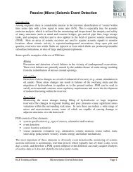
to process. Figure 45 shows the<br />
graphical output which appears<br />
once the appropriate seismic file<br />
has been selected. At the top of<br />
this figure there are four<br />
Figure 45: Main graphical interface in View -> Seismic Data<br />
software option<br />
checkboxes (Filter,<br />
Overlay, FFT and Display Pre-Trigger), and the numeric values of the time<br />
and amplitude at the current location of the graphical crosshair. Placing a check and removing a<br />
check within checkbox Display Pre-trigger will result in the display and removal of pre-trigger<br />
data, respectively. It should be noted that Display Pre-trigger should be unchecked when<br />
determining the Signal Decay Initial Time Decay as outlined in Section 3.5.<br />
If the Filter check box is selected the graphical output shown in Figure 46 appears, which shows<br />
the graphical results after specifying a bandpass of 30 to 100 Hz. The user may then overlay the<br />
unfiltered seismic trace onto the filtered trace by selecting checkbox Overlay as illustrated in<br />
Figure 47. The smoothed Fast Fourier Transform (FFT) of either the unfiltered or filtered<br />
seismic trace is derived and displayed by selecting checkbox FFT. The frequency spectrum of<br />
the filtered trace is displayed if the checkbox Filter is selected along with the FFT checkbox.<br />
Otherwise the unfiltered seismic trace’s frequency spectrum is displayed. Figure 48 shows the<br />
frequency spectrum of the unfiltered data file shown in Figure 45.<br />
Version 11.1.0 Page 29