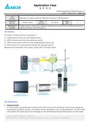
DVP-PLC Application Examples of Programming ... - Delta Electronics
DVP-PLC Application Examples of Programming ... - Delta Electronics
DVP-PLC Application Examples of Programming ... - Delta Electronics

Create successful ePaper yourself
Turn your PDF publications into a flip-book with our unique Google optimized e-Paper software.
Foreword<br />
Industrial Automation Business Unit (IABU) <strong>of</strong> <strong>Delta</strong> <strong>Electronics</strong> focuses our<br />
expertise on "Drive, Motion and Control" with our knowledge and experience in<br />
automation control. Our R&D teams continue researching and developing key<br />
technologies, producing innovative products in industrial automation; for example many<br />
OEM’s use our automation products for processing machines used in the food industry,<br />
textile industry, chemical industry, electronics industry, metal industry and plastic<br />
industry. Our automation equipment is also used in the pharmaceutical industry, printing<br />
industry, as well as for energy saving air-conditioning and water treatment facilities. In<br />
recent years, we have integrated our industrial automation products, developed<br />
industrial control networks, and <strong>of</strong>fered integration services to our clients around the<br />
world.<br />
<strong>Delta</strong>'s <strong>DVP</strong> series high-speed, stable and highly reliable <strong>PLC</strong>s are applied in various<br />
automation machines. In addition to its fast logic operations, abundant instructions,<br />
various extension cards and cost-effectiveness, <strong>DVP</strong> series <strong>PLC</strong>s support many<br />
communication protocols, seamlessly integrating the industrial automation control<br />
system as a whole.<br />
To meet users’ needs for <strong>DVP</strong>-<strong>PLC</strong> programming examples, we provide examples <strong>of</strong><br />
basic instructions including sequential/position control, timed counting and input/output<br />
control in <strong>DVP</strong>-<strong>PLC</strong> <strong>Application</strong> <strong>Examples</strong>. In addition, in this manual we also provides<br />
examples <strong>of</strong> advanced instructions including elementary arithmetic operations, data<br />
processing, high speed input/output control, network connection, and <strong>PLC</strong><br />
communication(AC motor drive / temperature controller / servo motor). <strong>DVP</strong>-<strong>PLC</strong><br />
<strong>Application</strong> <strong>Examples</strong> includes most common applications in automation control, such<br />
as parking lot entry/exit control, material mixing, stock monitoring, level monitoring,<br />
traffic lights control, and conveyer belt control. This manual explains methods for<br />
applying basic instructions as well as advanced instructions <strong>of</strong> <strong>DVP</strong>-<strong>PLC</strong> to accomplish<br />
the field application purposes. Users can easily understand how <strong>DVP</strong>-<strong>PLC</strong> features in<br />
automation applications through this manual. By referring to our <strong>DVP</strong>-<strong>PLC</strong> <strong>Application</strong><br />
Manual- 【 <strong>Programming</strong> 】 , users can also apply <strong>DVP</strong>-<strong>PLC</strong> efficiently on particular<br />
purposes and fulfill various control requirements in industrial automation.
<strong>DVP</strong>-<strong>PLC</strong> <strong>Application</strong> <strong>Examples</strong><br />
1. Basic Program Design <strong>Examples</strong><br />
CONTENTS<br />
1.1 Normally Closed Contact in Series Connection........................................ 1-1<br />
1.2 Block in Parallel Connection................................................................... 1-2<br />
1.3 Rising-edge Pulse Output for One Scan Cycle......................................... 1-3<br />
1.4 Falling-edge Pulse Output for One Scan Cycle ........................................ 1-4<br />
1.5 Latching Control Circuit.......................................................................... 1-5<br />
1.6 Interlock Control Circuit ......................................................................... 1-6<br />
1.7 Automatic Parameter Initialization When Powered Up .............................. 1-7<br />
1.8 Common Latched Circuit and SET/RST Instructions <strong>Application</strong> ............... 1-8<br />
1.9 SET/RST - Latched and Unlatched Circuit............................................... 1-9<br />
1.10 Alternate Output Circuit (With Latched Function) ................................... 1-10<br />
1.11 Conditional Control Circuit.................................................................... 1-12<br />
1.12 First-in Priority Circuit .......................................................................... 1-13<br />
1.13 Last-in Priority Circuit .......................................................................... 1-15<br />
1.14 Entry/Exit Control <strong>of</strong> the Underground Car Park..................................... 1-16<br />
1.15 Forward/Reverse Control for the Three-Phase Asynchronous Motor ....... 1-18<br />
1.16 Selective Execution <strong>of</strong> Programs .......................................................... 1-19<br />
1.17 MC/MCR - Manual/Auto Control ............................................................ 1-21<br />
1.18 STL Manual/Auto Control...................................................................... 1-24<br />
2. Counter Design <strong>Examples</strong><br />
2.1 Product Mass Packaging ........................................................................ 2-1<br />
2.2 Daily Production Record (16-bit Counting Up Latched Counter)................ 2-2<br />
2.3 Products Amount Calculation (32-bit Counting Up/Down Counter) ............ 2-4<br />
2.4 24-hour Clock Operated by 3 Counters ................................................... 2-5<br />
i
ii<br />
2.5 A B-phase Pulse High-speed Counter ..................................................... 2-6<br />
3. Timer Design <strong>Examples</strong><br />
3.1 Delay OFF Program ............................................................................... 3-1<br />
3.2 Delay ON Program................................................................................. 3-2<br />
3.3 Delay ON/OFF Program ......................................................................... 3-3<br />
3.4 Sequential Delay Output (Starting 3 Motors Sequentially) ........................ 3-4<br />
3.5 Pulse-Width Modulation ......................................................................... 3-6<br />
3.6 Artificial Fishpond Water Level Monitoring System (Flashing Circuit) ........ 3-7<br />
3.7 Burn-in Test System (Timing Extension) .................................................. 3-9<br />
3.8 Star-<strong>Delta</strong> Reduced Voltage Starter Control............................................. 3-11<br />
3.9 Automatic Door Control .......................................................................... 3-13<br />
3.10 Automatic Liquids Mixing Control System .............................................. 3-15<br />
3.11 Automatic C<strong>of</strong>fee Maker........................................................................ 3-17<br />
3.12 Automatic Urinal Flushing Control Program ........................................... 3-19<br />
3.13 Performing Accumulative Function with Normal Timer ............................ 3-21<br />
3.14 Performing Teaching Function with Normal Timer .................................. 3-23<br />
3.15 Auto Interruption Timer......................................................................... 3-25<br />
3.16 Interesting Fountain ............................................................................. 3-27<br />
3.17 Traffic Lights Control............................................................................ 3-29<br />
4. Index Registers E, F Design <strong>Examples</strong><br />
4.1 Summation <strong>of</strong> Continuous D Registers .................................................... 4-1<br />
4.2 Parameter Setting for Product Recipe ..................................................... 4-3<br />
4.3 Controlling Voltage Output <strong>of</strong> 2 <strong>DVP</strong>-04DA by 8 VRs (Variable Resistors) . 4-5<br />
5. Loop Instruction Design <strong>Examples</strong><br />
5.1 Recipe Setting by CJ Instruction............................................................. 5-1<br />
5.2 Reservoir Level Control.......................................................................... 5-3<br />
5.3 Fire Alarm in the Office (Interruption <strong>Application</strong>) .................................... 5-5<br />
5.4 Auto Lock up System in the Supermarket (FOR ~ NEXT) ......................... 5-7
6. Data Transmission and Comparison Design <strong>Examples</strong><br />
6.1 CMP - Material Mixing Machine .............................................................. 6-1<br />
6.2 ZCP - Water Level Alarm Control ............................................................ 6-3<br />
6.3 BMOV - Multiple History Data Backup ..................................................... 6-4<br />
6.4 FMOV - Single Data Broadcasting .......................................................... 6-5<br />
6.5 CML - Color Lights Flashing ................................................................... 6-7<br />
6.6 XCH - Exchanging the Upper and Lower 8 bits in a Register .................... 6-8<br />
6.7 DIP Switch Input and 7-segment Display Output...................................... 6-9<br />
7. Elementary Arithmetic Operations Design <strong>Examples</strong><br />
7.1 Accurate Pipe Flow Measurement ........................................................... 7-1<br />
7.2 INC/DEC - Fine Tuning by JOG Control................................................... 7-3<br />
7.3 NEG - Displacement Reverse Control ..................................................... 7-5<br />
8. Rotation and Shift Design <strong>Examples</strong><br />
8.1 ROL/ROR - Neon Lamp Design .............................................................. 8-1<br />
8.2 SFTL - Defective Product Detect............................................................. 8-3<br />
8.3 WSFL - Automatic Sorting Mixed Products .............................................. 8-5<br />
8.4 SFWR/SFRD - Room Service Call Control............................................... 8-8<br />
9. Data Processing Design <strong>Examples</strong><br />
9.1 ENCO/DECO - Encoding and Decoding................................................... 9-1<br />
9.2 SUM/BON - Checking and Counting the Number <strong>of</strong> “1” ............................ 9-3<br />
9.3 MEAN/SQR - Mean Value and Square Root............................................. 9-4<br />
9.4 MEMR/MEMW - File Register Access...................................................... 9-5<br />
9.5 ANS/ANR - Level Monitoring Alarm System ............................................. 9-7<br />
9.6 SORT - Sorting Acquired Data ................................................................ 9-8<br />
9.7 SER - Room Temperature Monitoring ...................................................... 9-10<br />
10. High-speed Input/Output Design <strong>Examples</strong><br />
10.1 REF/REFF - DI/DO Refreshment and DI Filter Time Setting ................... 10-1<br />
10.2 DHSCS - Cutting Machine Control ........................................................ 10-3<br />
10.3 DHSZ/DHSCR - Multi-segment Coater Control....................................... 10-4<br />
iii
iv<br />
10.4 SPD - Wheel Rotation Speed Measurement........................................... 10-6<br />
10.5 PLSY - Production Line Control Program............................................... 10-7<br />
10.6 PWM - Sprayer Valve Control Program.................................................. 10-9<br />
10.7 PLSR - Servo Motor Acceleration/Deceleration Control .......................... 10-11<br />
11. Floating Point Operation Design <strong>Examples</strong><br />
11.1 Elementary Arithmetic for Integer and Floating Point.............................. 11-1<br />
11.2 Elementary Arithmetic for Floating Point................................................ 11-4<br />
12. Communication Design <strong>Examples</strong><br />
Introduction................................................................................................. 12-1<br />
12.1 Communication between <strong>PLC</strong> and <strong>Delta</strong> VFD-M Series AC Motor Drive .. 12-5<br />
12.2 Communication between <strong>PLC</strong> and <strong>Delta</strong> VFD-B Series AC Motor Drive... 12-8<br />
12.3 Communication between <strong>PLC</strong> and <strong>Delta</strong> VFD-V Series AC Motor Drive... 12-11<br />
12.4 Communication between <strong>PLC</strong> and <strong>Delta</strong> ASD-A Series AC Servo Drive... 12-14<br />
12.5 Communication between <strong>PLC</strong> and <strong>Delta</strong> ASD-A Series AC Servo Drive... 12-18<br />
12.6 Communication between <strong>PLC</strong> and <strong>Delta</strong> DTA Temperature Controller ..... 12-22<br />
12.7 Communication between <strong>PLC</strong> and <strong>Delta</strong> DTB Temperature Controller ..... 12-25<br />
12.8 <strong>PLC</strong> LINK 16 Slaves and Read/Write 16 Data (Word)............................. 12-28<br />
12.9 <strong>PLC</strong> LINK 32 Slaves and Read/Write 100 Data (Word) ........................... 12-31<br />
12.10 LINK between <strong>PLC</strong>, <strong>Delta</strong> AC Motor Drive and AC Servo Drive ............. 12-34<br />
12.11 LINK between <strong>PLC</strong>, <strong>Delta</strong> DTA and DTB Temperature Controllers ......... 12-38<br />
12.12 Controlling START/STOP <strong>of</strong> 2 <strong>DVP</strong> <strong>PLC</strong>s through Communication ........ 12-41<br />
12.13 Communication between <strong>Delta</strong> <strong>PLC</strong> and Siemens MM420 Frequency Inverter<br />
........................................................................................................ 12-45<br />
12.14 Communication between <strong>Delta</strong> <strong>PLC</strong> and Danfoss VLT6000 Series Adjustable<br />
Frequency Drive ................................................................................ 12-50<br />
13. Real Time Calendar Time Design <strong>Examples</strong><br />
13.1 TRD/TWR/TCMP - Office Bell Timing Control......................................... 13-1<br />
13.2 TRD/TZCP - Control <strong>of</strong> Warehouse Automatic Door ............................... 13-3<br />
13.3 HOUR - Control <strong>of</strong> Switching Motors after a Long Time Running............. 13-6
14. Simple Positioning Design <strong>Examples</strong><br />
14.1 Simple positioning Demonstration System <strong>of</strong> <strong>Delta</strong> ASDA AC Servo Drive14-1<br />
14.2 Draw DELTA LOGO by 2-axis Synchronous Motion ................................ 14-6<br />
15. Handy Instruction Design <strong>Examples</strong><br />
15.1 ALT - Auto Blackboard Cleaner ............................................................. 15-1<br />
15.2 RAMP - Ramp Control <strong>of</strong> Crane ............................................................ 15-3<br />
15.3 INCD - Traffic Lights Control (Incremental Drum Sequencer) .................. 15-6<br />
15.4 ABSD - Adding Materials in Different Intervals (Absolute Drum Sequencer)15-9<br />
15.5 IST - Electroplating Process Auto Control.............................................. 15-12<br />
15.6 FTC - Fuzzy Temperature Control <strong>of</strong> the Oven....................................... 15-18<br />
15.7 PID - Oven Temperature Control (Auto-tuning for PID Temperature Control)<br />
.................................................................................................................. 15-22<br />
16. Network Connection Design <strong>Examples</strong><br />
16.1 Ethernet Connection ............................................................................ 16-1<br />
16.2 DeviceNet Connection.......................................................................... 16-6<br />
16.3 CANopen Connection ........................................................................... 16-9<br />
16.4 RTU-485 Connection............................................................................ 16-12<br />
17. Index.....................................................................................17-1<br />
v
1.1 Normally Closed Contact in Series Connection<br />
X1<br />
X0<br />
1. Basic Program Design <strong>Examples</strong><br />
Control Purpose:<br />
Detecting the standing bottles on the conveyor and pushing the fallen bottles out<br />
Devices:<br />
Control Program:<br />
Y0<br />
Device Function<br />
X0 X0 = ON when the detected input signal from the bottle-bottom is sheltered.<br />
X1 X1 = ON when the detected input signal from the bottle-neck is sheltered.<br />
Y0 Pneumatic pushing pole<br />
X0 X1<br />
Program Description:<br />
If the bottle on the conveyor belt is upstanding, the input signal from monitoring photocell at both<br />
bottle-bottom and bottle-neck will be detected. In this case, X0 = ON, and X1 = ON. The normally<br />
open (NO) contact X0 will be activated as well as the normally closed (NC) contact X1. Y0 remains<br />
OFF and pneumatic pushing pole will not perform any action.<br />
If the bottle from the conveyor belt is down, only the input signal from monitoring photocell at the<br />
bottle-bottom will be detected. In this case, X0 = ON, X1 = OFF. The state <strong>of</strong> output YO will be ON<br />
because the NO contact X0 activates and the NC contact X1 remains OFF. The pneumatic pushing<br />
pole will push the fallen bottle out <strong>of</strong> the conveyor belt.<br />
<strong>DVP</strong>-<strong>PLC</strong> <strong>Application</strong> <strong>Examples</strong> 1-1<br />
Y0
1. Basic Program Design <strong>Examples</strong><br />
1.2 Block in Parallel Connection<br />
1-2<br />
Y0<br />
Control Purpose:<br />
Setting up a lighting system for users to switch on/<strong>of</strong>f the light whether they are at the bottom or<br />
the top <strong>of</strong> the stairs.<br />
Devices:<br />
Control Program:<br />
Device Function<br />
X0 X0 turns ON when the bottom switch is turned to the right<br />
X1 X1 turns ON when the top switch is turned to the right.<br />
Y1 Stair light<br />
X0<br />
X0<br />
X1<br />
X1<br />
Program Description:<br />
If the states <strong>of</strong> the bottom switch and the top switch are the same, both ON or OFF, the light will<br />
be ON. If different, one is ON and the other is OFF, the light will be OFF.<br />
When the light is OFF, users can turn on the light by changing the state <strong>of</strong> either top switch at the<br />
bottom switch <strong>of</strong> the stairs. Likewise, when the light is ON, users can turn <strong>of</strong>f the light by<br />
changing the state <strong>of</strong> one <strong>of</strong> the two switches..<br />
X1<br />
X0<br />
Y0<br />
<strong>DVP</strong>-<strong>PLC</strong> <strong>Application</strong> <strong>Examples</strong>
1.3 Rising-edge Pulse Output for One Scan Cycle<br />
1. Basic Program Design <strong>Examples</strong><br />
Control Purpose:<br />
Creating a pulse <strong>of</strong> one program scan cycle as the condition to trigger the indicator or other devices<br />
when the switch (X0) is turned on.<br />
Devices:<br />
X0<br />
M10<br />
Y0<br />
Control Program:<br />
One scan cycle<br />
Device Function<br />
X0 Switch (OFF→ON)<br />
M10 Creating a trigger pulse for one program scan cycle<br />
Y0 Indicator<br />
X0<br />
M10<br />
Program Description:<br />
PLS<br />
M10<br />
SET Y0<br />
M10 turns on for one scan cycle<br />
When X0 is turned on (Rising-edge triggered), PLS instruction will be executed, and M10 will<br />
send a pulse for one program scan cycle.<br />
When M10 = ON, [SET Y0] instruction will be executed and Y0 will be ON. In this case, the<br />
indicator will be lighted, and other devices will be activated as well.<br />
<strong>DVP</strong>-<strong>PLC</strong> <strong>Application</strong> <strong>Examples</strong> 1-3
1. Basic Program Design <strong>Examples</strong><br />
1.4 Falling-edge Pulse Output for One Scan Cycle<br />
1-4<br />
X0<br />
Y0(Electromagnetic valve)<br />
Control Purpose:<br />
Creating a pulse <strong>of</strong> one program scan cycle as the condition to trigger the electromagnetic valve or<br />
other devices when the switch is turned <strong>of</strong>f.<br />
Devices:<br />
X0<br />
M10<br />
Y0<br />
Control Program:<br />
Program Description:<br />
One scan cycle<br />
Device Function<br />
X0 Switch(ON→OFF)<br />
M10 Creating a trigger pulse for one program scan cycle<br />
Y0 Electromagnetic valve<br />
X0<br />
M10<br />
PLF<br />
M10<br />
RST Y0<br />
M10 turns on for one scan cycle<br />
Y0 = OFF<br />
When X0 is turned on (Falling-edge triggered), PLF instruction will be executed, and M10<br />
will send a pulse for one program scan cycle.<br />
When M10 = ON, [RST Y0] instruction will be executed and Y0 will be OFF. In this case, the<br />
electromagnetic valve will be shut down.<br />
<strong>DVP</strong>-<strong>PLC</strong> <strong>Application</strong> <strong>Examples</strong>
1.5 Latching Control Circuit<br />
Control Purpose:<br />
Y0<br />
1. Basic Program Design <strong>Examples</strong><br />
X0<br />
START<br />
X1<br />
STOP<br />
X2<br />
TEST<br />
Controlling the running state <strong>of</strong> the ceiling-fan by pressing START and STOP.<br />
Checking if the ceiling-fan is running normally by pressing TEST.<br />
Devices:<br />
Control Program:<br />
Device Function<br />
X0 Press START, X0 = ON.<br />
X1 Press STO, X1 = ON.<br />
X2 Press TEST, X2 = ON.<br />
X3 Error signal<br />
Y1 Ceiling-fan motor control signal<br />
X0<br />
Y1<br />
X2<br />
X1<br />
TEST button<br />
X3<br />
Error Signal<br />
Program Description:<br />
Press START lightly and X0 = ON. The ceiling-fan will keep running if no error occurred (X3<br />
= OFF). The action can be practiced by a latching circuit which takes output Y1 as one <strong>of</strong> the<br />
input condition to keep the fan running even if the START button is not pressed.<br />
When STOP is pressed, X1 = ON and Y1 = OFF. The ceiling-fan will stop running.<br />
If error occur (X3 = ON), Y1 will be OFF and the ceiling-fan will stop running.<br />
When TEST is pressed (X2 = ON), Y1 = ON. The ceiling-fan will start running if no error<br />
occurred (X3 = OFF). On the contrary, when TEST is released, the ceiling-fan will stop<br />
running. The testing function is performed by this process.<br />
<strong>DVP</strong>-<strong>PLC</strong> <strong>Application</strong> <strong>Examples</strong> 1-5<br />
Y1
1. Basic Program Design <strong>Examples</strong><br />
1.6 Interlock Control Circuit<br />
1-6<br />
Y0<br />
X0 X1<br />
Control Purpose:<br />
The Entry/Exit <strong>of</strong> the parking lot is a single lane passage. By controlling the indicators, the program<br />
ensures that only one car can pass through the Entry/Exit so as to prevent car accident between<br />
entering and leaving cars<br />
Devices:<br />
Control Program<br />
X0<br />
Device Function<br />
X0 Car entering sensor. When a car passes through the sensor, X0 = ON.<br />
X1 Car leaving sensor. When a car passes through the sensor, X1 = ON.<br />
Y0 Entering car indicator(ON means “GO”, OFF means “STOP”)<br />
Y1 Leaving car indicator(ON means “GO”, OFF means “STOP”)<br />
Y1<br />
X1 Y0<br />
Y0<br />
Y1<br />
Entering Indicator<br />
Leaving Indicator<br />
Program Description:<br />
In the parking lot, there are two indicators individually directing the entering and leaving cars.<br />
By the interlock control circuit, only one indicator will show “GO” signal and the car accident<br />
will thus be prevented.<br />
When an entering car draws near the vehicle control barrier, X0 will be ON and so will Y0.<br />
The entering car indicator will show “GO”. At the same time, the leaving car indicator will<br />
show “STOP.” Car entering is allowed but leaving is prohibited in this case.<br />
When a leaving car draws near the vehicle control barrier, X1 will be ON and so will Y1. The<br />
leaving car indicator will show “GO” and the entering car indicator will show “STOP.”<br />
Y1<br />
<strong>DVP</strong>-<strong>PLC</strong> <strong>Application</strong> <strong>Examples</strong>
1.7 Automatic Parameter Initialization When Powered Up<br />
1. Basic Program Design <strong>Examples</strong><br />
Initialization button<br />
Control Purpose:<br />
When the machine is powered up, all the parameters will be initialized automatically and the<br />
machine will be ready. Users don’t need to set the parameters manually.<br />
Users can initialize parameters by pressing Initialization button at any time when the<br />
machine is running.<br />
Devices:<br />
Control Program:<br />
X1<br />
M1002<br />
M10<br />
Device Function<br />
X1 Initialization button. X1 will be ON when pressed<br />
M1002 Creating a pulse when <strong>PLC</strong> is powered on<br />
M10 Creating a trigger pulse for one scan cycle<br />
D1120 <strong>PLC</strong> COM2 communication protocol<br />
D1121 <strong>PLC</strong> communication address<br />
Y0 Parameter initialization completed signal<br />
PLS M10<br />
MOV H86 D1120<br />
MOV K1 D1121<br />
SET Y0<br />
Program Description:<br />
When <strong>PLC</strong> begins running, M1002 will be ON once and create a pulse with the width <strong>of</strong> one<br />
scan cycle. This action will be executed for just once during the <strong>PLC</strong> running process and is<br />
generally used to initialize devices such as D (data register), C (counter) and S (step point)<br />
By pressing X1, users can initialize parameters at any time during the program running<br />
process, that is, setting <strong>PLC</strong> Slave ID as No. 1, COM2 communication format as 9600, 7, E,<br />
1 and Y0 to be ON.<br />
<strong>DVP</strong>-<strong>PLC</strong> <strong>Application</strong> <strong>Examples</strong> 1-7<br />
X1
1. Basic Program Design <strong>Examples</strong><br />
1.8 Common Latched Circuit and SET/RST Instructions <strong>Application</strong><br />
Control Purpose:<br />
Turn on the switch, the light will be ON; turn <strong>of</strong>f the switch, the light will be OFF.<br />
Devices:<br />
Control Program:<br />
1-8<br />
Device Function<br />
X0 Switch-on button. X0 will be ON when pressed<br />
X1 Switch-<strong>of</strong>f button. X1 will be ON when pressed<br />
Y0 Indicator<br />
Common Latched Circuit<br />
X0<br />
Y0<br />
X1<br />
Latched Circuit for SET/RST Instructions<br />
X0<br />
X1<br />
Program Description:<br />
Y0<br />
SET Y0<br />
RST Y0<br />
In the above examples, when X0 goes from OFF to ON, Y0 will stay in ON state. When X1<br />
goes from OFF to ON, Y1 will stay in OFF state<br />
When X0 and X1 are enabled at the same time, it will be “Stop First”, that is, Y1 and the<br />
indicator will be OFF.<br />
<strong>DVP</strong>-<strong>PLC</strong> <strong>Application</strong> <strong>Examples</strong>
1.9 SET/RST - Latched and Unlatched Circuit<br />
X2<br />
1. Basic Program Design <strong>Examples</strong><br />
X0<br />
START<br />
Control Purpose:<br />
Press START, the pump begins to pump out the water; press STOP or when the water is<br />
empty, the pump stops working.<br />
Devices:<br />
Control Program:<br />
<strong>DVP</strong>-<strong>PLC</strong> <strong>Application</strong> <strong>Examples</strong> 1-9<br />
Y0<br />
X1<br />
STOP<br />
Device Function<br />
X0 START button. X0 will be ON when pressed<br />
X1 STOP button. X1 will be ON when pressed<br />
X2 Level detector. X2 will be ON if there is water in the container<br />
M0 Trigger pulse for one scan cycle<br />
Y0 Pump motor<br />
X0<br />
X1<br />
X2<br />
M0<br />
X2<br />
X1<br />
SET Y0<br />
PLS M0<br />
RST Y0<br />
Program Description:<br />
X2 will be ON If there is water in the container. When START is pressed, X0 = ON, and SET<br />
instruction will be executed. Y0 will be set, and the pump motor begins pumping the water.<br />
There are two situations for stopping the motor. First, when STOP is pressed, X1 = ON. PLS<br />
instruction will be executed and M0 will be ON for one scan cycle. RST instruction will thus<br />
be executed, and Y0 will be reset to stop pumping. Second, when the water in the<br />
container is empty, X2 will be OFF and PLS instruction will be executed to trigger M0 for<br />
resetting Y0. In this case, the pump motor will stop pumping as well.
1. Basic Program Design <strong>Examples</strong><br />
1.10 Alternate Output Circuit (With Latched Function)<br />
Control Purpose:<br />
Setting the light ON by pressing the switch for the 1 st time, the 3 rd time, 5 th time, etc.; setting<br />
the light OFF by pressing the switch for the 2 nd time, 4 th time, 6 th time, etc.<br />
Restoring the indicator to the state before power <strong>of</strong>f when the device is powered up again.<br />
Devices:<br />
Control Program:<br />
X1<br />
1-10<br />
M10<br />
M10<br />
Device Function<br />
X1 Light switch. X1 will be ON when the button is pressed<br />
M10 Trigger pulse for one scan cycle<br />
M512 If X1 is pressed for odd number <strong>of</strong> times, M512 ON, M513 = OFF.<br />
M513 If X1 is pressed for even number <strong>of</strong> times, M512 = OFF, M513 = ON.<br />
Y1 Indicator<br />
Y1<br />
Y1<br />
M512 M513<br />
Y1<br />
PLS M10<br />
SET<br />
RST<br />
SET<br />
RST<br />
Y1<br />
M512<br />
M513<br />
M513<br />
M512<br />
Trigger pulse for one scan cycle<br />
If X1 is pressed for odd number<br />
<strong>of</strong> times, M512=ON, M513=OFF<br />
If X1 is pressed for even number<br />
<strong>of</strong> times, M512=OFF, M513=ON<br />
Y1 will be ON/OFF if X1 is<br />
pressed for odd/even number <strong>of</strong> times<br />
Program Description:<br />
Pressing X1 for the 1 st time (or odd number <strong>of</strong> times):<br />
When the switch X1 is pressed, X1 will be ON and the [PLS M10] instruction will be<br />
executed for triggering M10 to be ON for one scan cycle. In this case, M10 is ON and Y1 is<br />
OFF, SET and RST instructions at line 2 will thus be executed. On the contrary, SET and<br />
RST instructions at line 3 will not be executed due to the open loop <strong>of</strong> Y1. At line 4, coil Y1 is<br />
ON because <strong>of</strong> the results <strong>of</strong> Line 2: M512 is ON and M513 is OFF. When the 2 nd scan cycle<br />
is started, SET/RST at both line 2 and line 3 will not be executed because M10 is OFF in this<br />
scan cycle. As a result, the light will be ON until the switch is pressed next time.<br />
Pressing X1 for the 2 nd time (or even number <strong>of</strong> times):<br />
When the switch X1 is pressed again, X1 will be ON and M10 will be ON for one scan cycle.<br />
According to the result <strong>of</strong> pressing X1 for the first time, the state <strong>of</strong> Y1 has been ON.<br />
SET/RST instructions at line 3 will thus be executed. In addition, SET/RST instructions at<br />
<strong>DVP</strong>-<strong>PLC</strong> <strong>Application</strong> <strong>Examples</strong>
1. Basic Program Design <strong>Examples</strong><br />
line 2 won’t be executed due to the open loop <strong>of</strong> Y1. In this case, M513 will be ON and M512<br />
will be OFF. When the 2 nd scan cycle is started, SET/RST at both line 2 and line 3 will not be<br />
executed because M10 is OFF in this scan cycle. As a result, the light will remain OFF until<br />
the switch is pressed next time.<br />
Alternate output(ON/OFF) function can also be performed by using API 66 ALT instruction<br />
<strong>DVP</strong>-<strong>PLC</strong> <strong>Application</strong> <strong>Examples</strong> 1-11
1. Basic Program Design <strong>Examples</strong><br />
1.11 Conditional Control Circuit<br />
1-12<br />
Oil Pump Motor<br />
Y0<br />
Y1<br />
X0<br />
X1<br />
X2<br />
START STOP<br />
Oil Pump Motor<br />
X3<br />
START STOP<br />
Main Motor<br />
Main Motor<br />
Control Purpose:<br />
Providing lube for the gear box before the lathe spindle starts to run which aims to ensure<br />
that the oil pump motor starts first and the main motor starts subsequently.<br />
Devices:<br />
Control Program:<br />
Device Content<br />
X0 Oil pump START button. X0 will be ON when pressed.<br />
X1 Main motor START button. X0 will be ON when pressed.<br />
X2 Oil pump STOP button. X2 will be ON when pressed.<br />
X3 Main motor STOP button. X3 will be ON when pressed.<br />
Y0 Oil pump motor<br />
Y1 Main motor<br />
X0<br />
Y0<br />
X1<br />
Y1<br />
X2<br />
X3 Y0<br />
Program Description:<br />
This program is a typical application <strong>of</strong> the conditional control circuit. Y0 = ON when Oil<br />
Pump START button is pressed. Therefore, the oil pump will start to provide lube for the gear<br />
box <strong>of</strong> main motor(Y1)<br />
Under the precondition <strong>of</strong> the operating state <strong>of</strong> the Oil pump, the main motor (Y1) will be<br />
ON when the Main motor START button is pressed.<br />
During the operation <strong>of</strong> main motor (Y1), oil pump (Y0) needs to provide lube continuously.<br />
The oil pump will be stopped when Oil pump STOP button X2 is activated, and the main<br />
motor will be stopped when Main motor STOP button X3 is activated.<br />
Y0<br />
Y1<br />
<strong>DVP</strong>-<strong>PLC</strong> <strong>Application</strong> <strong>Examples</strong>
1.12 First-in Priority Circuit<br />
小学生组 Pupil Group High 中学生组 School<br />
Student Group<br />
1. Basic Program Design <strong>Examples</strong><br />
X0 Y0 X1<br />
X2 Y1<br />
X3 Y2 X4<br />
主持人<br />
Control Purpose:<br />
There are 3 groups participating in the quiz game: pupils, high school students and<br />
pr<strong>of</strong>essors. If they want to get the chance <strong>of</strong> answering the question from the host, they<br />
must press the answer button on their table first. Other groups’ pressing will be invalid if any<br />
group gets the chance successfully<br />
There are 2 answer buttons for the pupil group and pr<strong>of</strong>essor group and 1 answer button for<br />
the high school student group. In order to give preferential treatment to the pupil group, Y0<br />
will be ON if any one <strong>of</strong> X0 or X1 is pressed. However, in order to limit the pr<strong>of</strong>essor group,<br />
Y2 will be ON when X3 and X4 are pressed at the same time. For the high school student<br />
group, Y1 will be ON when X2 is pressed.<br />
If the host presses X5 (Reset button), Y0, Y1 and Y2 will be OFF.<br />
Devices:<br />
Device Function<br />
<strong>DVP</strong>-<strong>PLC</strong> <strong>Application</strong> <strong>Examples</strong> 1-13<br />
X5<br />
X0 Answer button for pupil group<br />
X1 Answer button for pupil group<br />
X2 Answer button for high school student group<br />
X3 Answer button for pr<strong>of</strong>essor group<br />
X4 Answer button for pr<strong>of</strong>essor group<br />
X5 Reset button for host<br />
Y0 Indicator for pupil group<br />
Host<br />
Y1 Indicator for high school student group<br />
Y2 Indicator for pr<strong>of</strong>essor group<br />
教授组<br />
Pr<strong>of</strong>essor Group
1. Basic Program Design <strong>Examples</strong><br />
Control Program:<br />
1-14<br />
X5<br />
Reset button for the host<br />
X0<br />
X1<br />
Y0<br />
Y1 Y2<br />
X2 Y0 Y2<br />
Y1<br />
X3 X4 Y0<br />
Y2<br />
Y1<br />
MC N0<br />
Y0<br />
Y1<br />
Y2<br />
MCR<br />
Start <strong>of</strong> main control circuit<br />
Control <strong>of</strong> the pupil group<br />
Control <strong>of</strong> the high school student group<br />
Control <strong>of</strong> the pr<strong>of</strong>essor group<br />
N0<br />
End <strong>of</strong> main control circuit<br />
Program Description:<br />
If the host didn’t press the reset button X5, [MC N0] instruction will be executed and the<br />
program between MC and MCR will also be executed normally.<br />
The answer buttons are connected in parallel connection for the pupil group, and in series<br />
connection for the pr<strong>of</strong>essor group. For the high school student group, there is only one<br />
answer button. If one group presses the answer button successfully, its indicator will form a<br />
latching circuit, that is, the indicator will be ON even the button is released.<br />
Through the interlock circuit, any other button pressings will be invalid as long as one<br />
indicator is ON<br />
When the host presses the reset button, X5 = ON. [MC N0] instruction and the program<br />
between MC and MCR will not be executed. Y0, Y1 and Y2 will be out <strong>of</strong> power, and all the<br />
indicators for the 3 groups will be OFF. When the host releases the button, X5 = OFF. The<br />
program between MC and MCR will be executed normally again, and the new round will<br />
begin as well.<br />
<strong>DVP</strong>-<strong>PLC</strong> <strong>Application</strong> <strong>Examples</strong>
1.13 Last-in Priority Circuit<br />
Control Purpose:<br />
1. Basic Program Design <strong>Examples</strong><br />
There are 4 buttons corresponding to 4 indicators. The program is to turn on the indicators<br />
corresponding to pressed buttons and to turn <strong>of</strong>f the previous ON indicators.<br />
Devices:<br />
Control Program:<br />
X0<br />
X1<br />
X2<br />
X3<br />
M1000<br />
M11<br />
Device Function<br />
X0 Button 1. X0 will go from OFF to ON when pressed<br />
X1 Button 2. X1 will go from OFF to ON when pressed<br />
X2 Button 3. X2 will go from OFF to ON when pressed<br />
X3 Button 4. X3 will go from OFF to ON when pressed<br />
Y0 Indicator 1<br />
Y1 Indicator 2<br />
Y2 Indicator 3<br />
Y3 Indicator 4<br />
PLS M0<br />
PLS M1<br />
PLS M2<br />
PLS M3<br />
CMP K1M0 K0 M10<br />
MOV K1M0 K1Y0<br />
Program Description:<br />
When a button is pressed, the corresponding device X will go from OFF to ON. In this scan<br />
cycle, PLS instruction is executed, and the corresponding internal relay M is enabled as well.<br />
CMP instruction will be executed and the compared result is K1M0>0 which makes M10 ON<br />
but M11 OFF. [MOV K1M0 K1Y0] instruction will then be executed and sent out the state <strong>of</strong><br />
M to its corresponding output Y. At the same time, the previous ON indicator(Y) will be<br />
turned <strong>of</strong>f.<br />
When it comes to the 2 nd scan cycle, PLS instructions will not be executed and the value <strong>of</strong><br />
M0~M3 will be 0. Therefore, the CMP instruction will be executed and set M11 to be ON<br />
(K1M0 = 0). [MOV K1M0 K1Y0] instruction will not be executed, and the 0 state <strong>of</strong> device M<br />
will not be sent out, either. In this case, Output Y will remain its original state until any other<br />
button is pressed next time.<br />
<strong>DVP</strong>-<strong>PLC</strong> <strong>Application</strong> <strong>Examples</strong> 1-15
1. Basic Program Design <strong>Examples</strong><br />
1.14 Entry/Exit Control <strong>of</strong> the Underground Car Park<br />
Control Purpose:<br />
1-16<br />
Red Light Green Light<br />
Y1 Y2<br />
X1<br />
Entry/Exit <strong>of</strong> the Ground Floor<br />
Singa an<br />
l L e Passage<br />
Red Light Green Light<br />
Y1 Y2<br />
X2<br />
Entry/Exit <strong>of</strong> the Basement<br />
The entry/exit <strong>of</strong> the underground car park is a single lane passage which needs the traffic<br />
lights to control the cars. Red lights prohibit cars entering or leaving while green lights allow<br />
cars to enter or leave.<br />
When a car enters the passage from the entry <strong>of</strong> the ground floor, the red lights both on the<br />
ground floor and the basement will be ON, and the green lights will be OFF. Any car entering<br />
or leaving is prohibited during the process till the car passes through the passage completely.<br />
When the passage is clear, the green lights will be ON again and allow other cars entering<br />
from the ground floor or the basement.<br />
Similarly, when a car leaves the basement and enters the passage, any other car entering or<br />
leaving is prohibited till the car passes from the passage to the ground completely.<br />
When <strong>PLC</strong> runs, the initial setting <strong>of</strong> traffic lights will be green lights ON and red lights OFF.<br />
Devices:<br />
Device Function<br />
X1 Photoelectric switch at the ground floor entry/exit. X1 will be ON when a car passes.<br />
X2 Photoelectric switch at the basement entry/exit. X2 will be ON when a car passes.<br />
M1 M1 will be ON for one scan cycle when a car from the ground floor passes X1.<br />
M2 M2 will be ON for one scan cycle when a car from the basement passes X1.<br />
M3 M3 will be ON for one scan cycle when a car from the basement passes X2.<br />
M4 M4 will be ON for one scan cycle when a car from the ground floor passes X2<br />
M20 M20 = ON during the process <strong>of</strong> a car entering the passage from the ground floor.<br />
M30 M30 = ON during the process <strong>of</strong> a car entering the passage from the basement.<br />
Y1 Red lights at the entry/exit <strong>of</strong> the ground floor and the basement<br />
Y2 Green lights at the entry/exit <strong>of</strong> the ground floor and the basement<br />
<strong>DVP</strong>-<strong>PLC</strong> <strong>Application</strong> <strong>Examples</strong>
Control Program:<br />
M1002<br />
X1<br />
X2<br />
M1 M30<br />
M3 M20<br />
M4 M20<br />
M2 M30<br />
M4 M20<br />
M2 M30<br />
Program Description:<br />
RST Y1<br />
SET Y2<br />
PLS<br />
PLF M2<br />
SET M20<br />
PLS M3<br />
PLF M4<br />
SET M30<br />
SET Y1<br />
RST Y2<br />
RST Y1<br />
SET Y2<br />
RST M20<br />
RST M30<br />
1. Basic Program Design <strong>Examples</strong><br />
The green lights will be ON and<br />
the red lights will be OFF when<br />
the program is started<br />
M1 will be ON for one scan cycle<br />
when a car from the ground floor passes X1.<br />
M2 will be ON for one scan cycle<br />
when a car from the basement passes X1.<br />
M20=ON during the process <strong>of</strong> a car<br />
entering the passage from the ground floor.<br />
M3 will be ON for one scan cycle<br />
when a car from the basement passes X2.<br />
M4 will be ON for one scan cycle<br />
when a car from the ground floor passes X2.<br />
M30=ON during the process <strong>of</strong> a car<br />
entering the passage from the basement.<br />
When a car runs in the passage,<br />
the red lights will be ON and green lights will be OFF.<br />
When a car leaves the passage,<br />
the red lights will be OFF and green lights will be ON.<br />
When a car leaves the passage,<br />
M20 and M30 will be reseted.<br />
The ground floor and the basement share the same red light signal Y1 and green light signal<br />
Y2.<br />
The key <strong>of</strong> the program is to identify that the car is entering or leaving the passage at the<br />
ground floor entry/exit when M1 is ON to activate Y1 because [PLS M1] will be executed in<br />
both entering and leaving conditions. Therefore, the confirming signal M20 is required for<br />
confirming that the car is entering the passage from the ground floor.<br />
Also, it needs to identify that the car is entering or leaving the passage at the basement<br />
entry/exit when M3 is ON because [PLS M3] will be executed in both entering and leaving<br />
conditions. Therefore, the confirming signal M30 is required for confirming that the car is<br />
entering the passage from the basement.<br />
<strong>DVP</strong>-<strong>PLC</strong> <strong>Application</strong> <strong>Examples</strong> 1-17
1. Basic Program Design <strong>Examples</strong><br />
1.15 Forward/Reverse Control for the Three-Phase Asynchronous Motor<br />
Control Purpose:<br />
1-18<br />
Reverse<br />
Forward<br />
Forward<br />
Reverse<br />
Controlling the motor to run forward when Forward is pressed, run reverse when Reverse is<br />
pressed and stop when Stop is pressed.<br />
Devices:<br />
Control Program:<br />
X0<br />
Device Function<br />
Stop<br />
X0 Forward button <strong>of</strong> the motor. X0 will be ON when pressed<br />
X1 Reverse button <strong>of</strong> the motor. X1 will be ON when pressed<br />
X2 Stop button. X2 will be ON when pressed.<br />
T1 1 sec timer<br />
T2 1 sec timer<br />
Y0 Forward contactor<br />
Y1 Reverse contactor<br />
T0 X1 X2 Y1<br />
Y0<br />
X1<br />
T1 X0 X2 Y0<br />
Y1<br />
TMR T0 K10<br />
Y0<br />
TMR T1 K10<br />
Y1<br />
Program Description:<br />
X0 = ON when Forward is pressed. After 1 second, contactor Y0 will be enabled, and the<br />
motor begins to run forward. On the other hand, X1 = ON when Reverse is pressed. After 1<br />
second, contactor Y1 will be enabled, and the motor begins to run reverse. Besides, Y0 and<br />
Y1 will be disabled and the motor will stop running when X2 is pressed.<br />
The two timers in the program are used to avoid the interphase short-circuit when the motor<br />
changes its running mode. The short circuit may occur if another contactor is enabled<br />
instantly while the electric arc in the disabled contactor still exists.<br />
<strong>DVP</strong>-<strong>PLC</strong> <strong>Application</strong> <strong>Examples</strong>
1.16 Selective Execution <strong>of</strong> Programs<br />
Green<br />
X3<br />
Yellow X1 X2 Blue<br />
Control Purpose:<br />
Devices:<br />
Color Selection<br />
X0<br />
1. Basic Program Design <strong>Examples</strong><br />
Yellow Blue<br />
Y0 Y1<br />
There are pigments <strong>of</strong> 3 colors. By controlling different switches, operators can fill the cans<br />
with corresponding pigments.<br />
Device Function<br />
X0 Filling Start switch. X0 will be ON when turned on.<br />
X1 Yellow control switch. X1 will be ON when turned on.<br />
X2 Blue control switch. Turn it on, X2 will be On<br />
X3 Green (mixing <strong>of</strong> yellow and blue) control switch. X3 will be ON when turned on<br />
Y0 Yellow control valve<br />
Y1 Blue control valve<br />
<strong>DVP</strong>-<strong>PLC</strong> <strong>Application</strong> <strong>Examples</strong> 1-19
1. Basic Program Design <strong>Examples</strong><br />
Control Program<br />
1-20<br />
X1<br />
X3<br />
X0<br />
X2<br />
X3<br />
X0<br />
Program Description:<br />
MC N0<br />
Y0<br />
MCR N0<br />
MC N0<br />
Y1<br />
MCR<br />
Yellow control valve<br />
Blue control valve<br />
N0<br />
Filling yellow pigment<br />
Filling green pigment<br />
Filling blue pigment<br />
The master switch <strong>of</strong> filling control needs to be turned on (X0 = ON) before filling started.<br />
When both yellow and blue are filled at the same time, it will become green.<br />
When the switch <strong>of</strong> filling yellow pigment is turned on, X1 = ON. The first MC ~ MCR<br />
instruction will be executed. Y0 = ON, and the system begins to fill the yellow color.<br />
When the switch <strong>of</strong> filling blue pigment is turned on, X2 = ON. The second MC ~ MCR<br />
instruction will be executed. Y1 = ON, and the system begins to fill the blue color.<br />
When the switch <strong>of</strong> filling green pigment is turned on, X3 = ON, both <strong>of</strong> the two MC ~ MCR<br />
instructions will be executed, and the system begins to fill the green color.<br />
<strong>DVP</strong>-<strong>PLC</strong> <strong>Application</strong> <strong>Examples</strong>
1.17 MC/MCR - Manual/Auto Control<br />
Control Purpose:<br />
Devices:<br />
Conveyor A<br />
1. Basic Program Design <strong>Examples</strong><br />
Conveyor B<br />
<strong>DVP</strong>-<strong>PLC</strong> <strong>Application</strong> <strong>Examples</strong> 1-21<br />
Auto<br />
Manual<br />
X0<br />
X1<br />
Clip<br />
Transfer<br />
Release<br />
When the button Manual is pressed, the robotic arm will begin to execute the manual control<br />
process: pressing Clip to clip the product from conveyor A, pressing Transfer to move the<br />
product to the conveyor B, and pressing Release to release the product and send it away by<br />
conveyor B.<br />
When the button Auto is pressed, the robotic arm will begin to execute the auto control<br />
process once: clip product (keep holding this product before releasing) → transfer product<br />
(the action takes 2 sec) → release the product. Auto control process can be performed one<br />
more time if the button Auto is pressed again.<br />
Manual control process and auto control process are interlocked.<br />
Device Function<br />
X0 Auto button. X0 goes from OFF to ON when pressed.<br />
X1 Manual button. X1 goes from OFF to ON when pressed<br />
X2 Clip button. X2 will be ON when pressed.<br />
X3 Transfer button. X3 will be ON when pressed.<br />
X4 Release button. X4 will be ON when pressed.<br />
M0~M2 Auto control process<br />
M3~M5 Manual control process<br />
M10 Auto control selection<br />
M11 Manual control selection<br />
T0 2 sec timer<br />
Y0 Product clipping/releasing. Y0 is ON/OFF when clipping/releasing the product.<br />
Y1 Product transferring
1. Basic Program Design <strong>Examples</strong><br />
Control Program:<br />
1-22<br />
X0<br />
X1<br />
M10 M11<br />
M1000<br />
M1000<br />
T0<br />
M2<br />
M11<br />
X2<br />
X3<br />
X4<br />
M0<br />
M3<br />
M1<br />
M4<br />
M2<br />
M5<br />
T0<br />
M10<br />
SET<br />
RST<br />
SET<br />
RST<br />
MC<br />
M0<br />
TMR<br />
M1<br />
M2<br />
RST<br />
N0<br />
T0 K20<br />
M10<br />
MCR N0<br />
MC N0<br />
M3<br />
M4<br />
M5<br />
MCR N0<br />
SET<br />
Y1<br />
RST<br />
M10<br />
M11<br />
M11<br />
M10<br />
Y0<br />
Y0<br />
Product clipping<br />
Product Transferring<br />
Set auto control<br />
Set manual control<br />
Product releasing<br />
Auto control process<br />
Manual control process<br />
<strong>DVP</strong>-<strong>PLC</strong> <strong>Application</strong> <strong>Examples</strong>
Program Description:<br />
1. Basic Program Design <strong>Examples</strong><br />
When X0 goes from OFF to ON, the auto control process will be executed once, whereas<br />
when X1 goes from OFF to ON, the manual control process will be executed. In the manual<br />
control, the clipping and releasing actions require pressing the corresponding button for one<br />
time. However, the button Transfer should be pressed for 2 sec during the moving process<br />
till the product is moved to Conveyor B.<br />
X0 and X1 are interlocked. When the auto control process is executed, the robotic arm will<br />
perform the following actions: first “clipping”, then “transferring” (for 2 sec.), and “releasing.”<br />
When the manual control process is executed, the controlling actions will be performed by 3<br />
corresponding buttons: clipping product by turning on Y0, transferring product by pressing<br />
Y1 and releasing product by turning <strong>of</strong>f Y0.<br />
<strong>DVP</strong>-<strong>PLC</strong> <strong>Application</strong> <strong>Examples</strong> 1-23
1. Basic Program Design <strong>Examples</strong><br />
1.18 STL Manual/Auto Control<br />
Control Purpose:<br />
Devices:<br />
1-24<br />
Conveyor A<br />
Conveyor B<br />
Auto<br />
Manual<br />
X0<br />
X1<br />
Clip<br />
Transfer<br />
Release<br />
When the button Manual is pressed, the robotic arm will begin to execute the manual control<br />
process: pressing Clip to clip the product from conveyor A, pressing Transfer to move the<br />
product to the conveyor B, and pressing Release to release the product and send it away by<br />
conveyor B.<br />
When the button Auto is pressed, the robotic arm will begin to execute the auto control<br />
process once: clip product (keep holding this product before releasing) → transfer product<br />
(the action takes 2 sec) → release the product. Auto control process can be performed one<br />
more time if the button Auto is pressed again.<br />
Manual control process and auto control process are interlocked.<br />
Device Function<br />
X0 Auto button. X0 goes from OFF to ON when pressed.<br />
X1 Manual button. X1 goes from OFF to ON when pressed<br />
X2 Clip button. X2 will be ON when pressed.<br />
X3 Transfer button. X3 will be ON when pressed.<br />
X4 Release button. X4 will be ON when pressed.<br />
S0 Initial step<br />
S20 Auto control step<br />
S21 Manual control step<br />
T0 2 sec timer<br />
Y0 Product clipping/releasing. Y0 is ON/OFF when clipping/releasing the product<br />
Y1 Product transferring<br />
<strong>DVP</strong>-<strong>PLC</strong> <strong>Application</strong> <strong>Examples</strong>
Control Program:<br />
M1002<br />
S0 X0<br />
S<br />
S20<br />
S<br />
S21<br />
S<br />
Program Description:<br />
T0<br />
T0<br />
X1<br />
X2<br />
X3<br />
X4<br />
Y0<br />
1. Basic Program Design <strong>Examples</strong><br />
SET S0<br />
SET<br />
SET<br />
TMR T0 K20<br />
Y1<br />
RST<br />
S0<br />
Y1<br />
RET<br />
<strong>DVP</strong>-<strong>PLC</strong> <strong>Application</strong> <strong>Examples</strong> 1-25<br />
Y0<br />
Y0<br />
Clipping Product<br />
Transferring Product<br />
Releasing Product<br />
SET Y0 Clipping Product<br />
Transferring Product<br />
RST Y0 Releasing Product<br />
S0<br />
S20<br />
SET S21<br />
Auto Control Button<br />
Manual Control Button<br />
When X0 goes from OFF to ON, the step S20 will be set to execute auto control process one<br />
time, and the manual control process will be prohibited at the same time. Auto control<br />
process can be performed one more time if the button Auto is pressed again.<br />
The auto control process performed by the robotic arm: clipping product when X0 = ON<br />
(keep holding this product before releasing) → transferring product when Y1 = ON (the<br />
action takes 2 sec) → releasing the product when Y0 = OFF.<br />
When X1 goes from OFF to ON, the step S21 will be set to execute manual control process<br />
one time, and the auto control process will be prohibited at the same time.<br />
The manual control process performed by the robotic arm: pressing Clip(X2) to clip the<br />
product from conveyor A, pressing Transfer(X3) to move the product to the conveyor B, and<br />
pressing Release(X4) to release the product and send it away by conveyor B.
1. Basic Program Design <strong>Examples</strong><br />
1-26<br />
MEMO<br />
<strong>DVP</strong>-<strong>PLC</strong> <strong>Application</strong> <strong>Examples</strong>
2.1 Product Mass Packaging<br />
Control Purpose:<br />
Devices:<br />
Control Program:<br />
X0<br />
2. Counter Design <strong>Examples</strong><br />
Once the photoelectric sensor detects 10 products, the robotic arm will begin to pack up.<br />
When the action is completed, the robotic arm and the counter will be reset.<br />
Device Function<br />
X0 Photoelectric sensor for counting products. X0 = ON when products are detected.<br />
X1 Robotic arm action completed sensor. X1 = ON when packing is completed.<br />
C0 Counter: 16-bit counting up (general purpose)<br />
Y0 Robotic arm for packing<br />
X0<br />
C0<br />
X1<br />
Program Description:<br />
CNT C0 K10<br />
Y0<br />
RST<br />
RST<br />
<strong>DVP</strong>-<strong>PLC</strong> <strong>Application</strong> <strong>Examples</strong> 2-1<br />
Y0<br />
C0<br />
Once the photoelectric sensor detects a product, X0 will go from OFF to ON once, and C0<br />
will count for one time.<br />
When the present value in C0 reaches 10, the Normally Open contact C0 will be closed. Y0<br />
= ON, and the robotic arm will begin to pack.<br />
When the packing is completed, the robotic arm action completed sensor will be enabled. X1<br />
will go from OFF to ON and RST instruction will be executed. Y0 and C0 will be reset for the<br />
next packing task.<br />
Y0<br />
X1
2. Counter Design <strong>Examples</strong><br />
2.2 Daily Production Record (16-bit Counting Up Latched Counter)<br />
2-2<br />
X0<br />
Control Purpose:<br />
Devices:<br />
Control Program:<br />
X1<br />
Clear<br />
Daily Quantity 今日完成 Completion<br />
456<br />
The production line may be powered <strong>of</strong>f accidentally or turned <strong>of</strong>f for noon break. The<br />
program is to control the counter to retain the counted number and resume counting after<br />
the power is ON again.<br />
When the daily production reaches 500, the target completed indicator will be ON to remind<br />
the operator for keeping a record.<br />
Press the Clear button to clear the history records. The counter will start counting from 0<br />
again.<br />
X0<br />
C120<br />
X1<br />
Program Description:<br />
Device Function<br />
X0 Photoelectric sensor. Once detecting the products, X0 will be ON.<br />
X1 Clear button<br />
C120 Counter: 16-bit counting up (latched)<br />
Y0 Target completed indicator<br />
CNT C120 K500<br />
Y0<br />
RST C120<br />
The latching counter is demanded for the situation <strong>of</strong> retaining data when power-<strong>of</strong>f.<br />
When a product is completed, C120 will count for one time. When the number reaches 500,<br />
<strong>DVP</strong>-<strong>PLC</strong> <strong>Application</strong> <strong>Examples</strong>
2. Counter Design <strong>Examples</strong><br />
target completed indicator Y0 will be ON.<br />
For different series <strong>of</strong> <strong>DVP</strong>-<strong>PLC</strong>, the setup range <strong>of</strong> 16-bit latching counter is different. C112<br />
~ C127 for ES/EX/SS series, C96 ~ C199 for SA/SX/SC series and C100 ~ C199 for EH<br />
series.<br />
<strong>DVP</strong>-<strong>PLC</strong> <strong>Application</strong> <strong>Examples</strong> 2-3
2. Counter Design <strong>Examples</strong><br />
2.3 Products Amount Calculation (32-bit Counting Up/Down Counter)<br />
Control Purpose:<br />
Devices:<br />
Control Program:<br />
2-4<br />
Entry Exit<br />
This program is used for monitoring the product amount in the warehouse by photoelectric<br />
sensors at both entry and exit. When the amount reaches 40,000, the alarm will be enabled.<br />
Device Function<br />
X0<br />
Photoelectric sensors for monitoring incoming goods. X0 = ON when incoming<br />
detected.<br />
X1<br />
Photoelectric sensors for monitoring outgoing goods. X1 = ON when outgoing<br />
detected.<br />
M1216 Counting mode <strong>of</strong> C216(ON: counting down)<br />
C216 32-bit counting up/down counter<br />
X0<br />
X1<br />
X0<br />
X1<br />
C216<br />
Program Description:<br />
Y0 Alarm<br />
RST M1216<br />
SET M1216<br />
DCNT C216 K40000<br />
Y0<br />
The key <strong>of</strong> this example is using the 32-bit addition/subtraction flag M1216 to control the<br />
counting up/ down <strong>of</strong> C216. When X0 goes from OFF to ON, M1216 = OFF, and C216 will<br />
count up; when X1 goes from OFF to ON, M1216 = ON, C216 will count down.<br />
When the present value <strong>of</strong> C216 reaches 40,000, C216 = ON, and the alarm Y0 will be<br />
enabled.<br />
<strong>DVP</strong>-<strong>PLC</strong> <strong>Application</strong> <strong>Examples</strong>
2.4 24-hour Clock Operated by 3 Counters<br />
Control Purpose:<br />
Hour Minute Second<br />
2. Counter Design <strong>Examples</strong><br />
<br />
Devices:<br />
Using 3 counters together with the flag <strong>of</strong> M1013 (1s clock pulse) to operate a 24-hour clock.<br />
Device Function<br />
Control Program:<br />
M1013<br />
C0<br />
C1<br />
C2<br />
Program Description:<br />
C0 count per second<br />
C1 count per minute<br />
C2 count per hour<br />
M1013 1s clock pulse<br />
CNT C0 K60<br />
CNT C1 K60<br />
RST C0<br />
CNT C2 K24<br />
RST C1<br />
RST C2<br />
The key <strong>of</strong> operating a 24-hour clock is to use M1013 (1s clock pulse). When the program is<br />
executed, C0 will count once per second. When the counted number reaches 60(1 minute),<br />
C0 = ON. C1 will count once, and C0 will be reset at the same time; similarly, when the<br />
counted number in C1 reaches 60(1 hour), C1 = ON. C2 will count once, and C1 will be<br />
reset at the same time. Furthermore, when the present value in C2 reaches 24, C2 will be<br />
reset, and the 24-hour counting process will start again.<br />
The 24-hour clock operates by using C0 to count “second”, C1 to count “minute” and C2 to<br />
count “hour.” In this clock, the value <strong>of</strong> “second”, “minute” and “hour” can be read by C0, C1<br />
and C2 correspondingly. When the set value <strong>of</strong> C2 is 12, the clock will be a 12-hour clock.<br />
<strong>DVP</strong>-<strong>PLC</strong> <strong>Application</strong> <strong>Examples</strong> 2-5
2. Counter Design <strong>Examples</strong><br />
2.5 A B-phase Pulse High-speed Counter<br />
2-6<br />
Wiring for Differential Input(high-speed, high-noise condition)<br />
<strong>DVP</strong>32EH00M High-speed Input<br />
X0+<br />
X0-<br />
X1+<br />
X1-<br />
Wiring for Differential Output<br />
Control Purpose:<br />
Devices:<br />
<strong>PLC</strong><br />
Y0<br />
Y1<br />
Twisted Pair Cable<br />
Y0+<br />
Y0-<br />
SG0<br />
Y1+<br />
Y1-<br />
A +<br />
A -<br />
B +<br />
B -<br />
A +<br />
A -<br />
Twisted Pair Cable<br />
B +<br />
B -<br />
A<br />
B<br />
Differntial Output<br />
Servo Driver<br />
Photocouple<br />
Input Wiring<br />
Line Receiver<br />
Input Wiring<br />
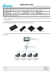
<strong>DVP</strong>32EH00M sends AB-phase pulse to control the servo at a speed <strong>of</strong> 10,000 pulses per<br />
second. The motor rotation will be encoded by the encoder and the result will be transferred to<br />
the input points (differential input) <strong>of</strong> <strong>PLC</strong> high-speed counter. If the counted value in <strong>PLC</strong><br />
high-speed counter is different from the number <strong>of</strong> pulse sent by the MPU, the alarm will be<br />
enabled.<br />
Device Function<br />
Y0 100KHz pulse output<br />
Y5 Alarm indicator<br />
M1013 1s clock pulse<br />
M1029 Pulse output completed flag<br />
D1220 Setting the first group output phase, CH0(Y0, Y1)<br />
C251 High-speed counter<br />
<strong>DVP</strong>-<strong>PLC</strong> <strong>Application</strong> <strong>Examples</strong>
Control Program:<br />
M1013<br />
M1000<br />
M1029<br />
Program Description:<br />
<strong>DVP</strong>-<strong>PLC</strong> <strong>Application</strong> <strong>Examples</strong><br />
DLD
2. Counter Design <strong>Examples</strong><br />
2-8<br />
MEMO<br />
<strong>DVP</strong>-<strong>PLC</strong> <strong>Application</strong> <strong>Examples</strong>
3.1 Delay OFF Program<br />
Control Purpose:<br />
Devices:<br />
Control Program:<br />
<strong>DVP</strong>-<strong>PLC</strong> <strong>Application</strong> <strong>Examples</strong><br />
3. Timer Design <strong>Examples</strong><br />
Enabling the indicator to be ON immediately and OFF after a 5 sec delay by the switch<br />
X1<br />
T0<br />
Y1<br />
Device Function<br />
X1 X1 = OFF when the switch is turned <strong>of</strong>f<br />
T1 5 sec timer. Time base = 100ms<br />
Y1 Output indicator<br />
X1 T1<br />
Y1<br />
X1<br />
Program Description:<br />
Y1<br />
TMR T1 K50<br />
5s<br />
Delay OFF for 5 sec<br />
X1 = ON when the switch is turned on. The NC (Normally Closed) contact X1 will be<br />
activated, and TMR instruction will not be executed. Coil T1 will be OFF and so will the NC<br />
contact T1. Because X1 = ON, the indicator Y1 will be ON and latched.<br />
X1 = OFF when the switch is turned <strong>of</strong>f. The NC contact X1 will not be activated, which<br />
makes TMR instruction executed. Indicator Y1 will remain ON by the latched circuit until T1<br />
reaches its set value.<br />
When timer T1 reaches its set value <strong>of</strong> 5 seconds, coil T1 will be ON. The NC contact T1 will<br />
be activated, which makes the indicator Y1 OFF.<br />
Delay OFF function can also be performed by using API 65 STMR instruction.<br />
3-1
3. Timer Design <strong>Examples</strong><br />
3.2 Delay ON Program<br />
Control Purpose:<br />
Devices:<br />
Control Program:<br />
3-2<br />
Enabling the indicator to be ON after a 3 sec delay and OFF immediately by the switch<br />
X1<br />
T1<br />
Program Description:<br />
X1<br />
T0<br />
Y1<br />
3s<br />
Device Function<br />
X1 X1 = ON when the switch is turned on<br />
T1 3 sec timer, time base = 100ms<br />
Y1 Output indicator<br />
TMR T1 K30 Delay ON for 3 sec<br />
Y1<br />
When X1 = ON, TMR instruction will be executed. Timer T1 will be ON and start counting for<br />
3 sec. When T1 reaches its set value, the NO (Normally Open) contact T1 will be activated<br />
and indicator YI will be ON.<br />
When X1 = OFF, TMR instruction will not be executed. Timer T1 will be OFF and so will NO<br />
contact T1. Therefore, the indicator Y1 will be OFF.<br />
<strong>DVP</strong>-<strong>PLC</strong> <strong>Application</strong> <strong>Examples</strong>
3.3 Delay ON/OFF Program<br />
Control Purpose:<br />
Devices:<br />
Control Program:<br />
<strong>DVP</strong>-<strong>PLC</strong> <strong>Application</strong> <strong>Examples</strong><br />
3. Timer Design <strong>Examples</strong><br />
Enabling the indicator to be ON after a 5 sec delay and OFF after a 3 sec delay by the<br />
switch<br />
X1<br />
X1<br />
X1<br />
Y1<br />
5s<br />
Device Function<br />
X1 X1 = ON when the switch is turned on.<br />
T0 5 sec timer, time base = 100ms<br />
T1 3 sec timer, time base = 100ms<br />
Y1 Output indicator<br />
T0 T1<br />
Y1<br />
Program Description:<br />
TMR T0 K50<br />
TMR T1 K30<br />
Y1<br />
3s<br />
Delay ON for 5 sec<br />
Delay OFF for 3 sec<br />
When X1 = ON, T0 will start counting for 5 sec. When T0 reaches its set value, the NO<br />
contact T0 will be ON while NC contact T1 will remain OFF, which makes the indicator Y1 to<br />
be ON and latched.<br />
When X1 = OFF, T1 will start counting for 3 sec. When T1 reaches its set value, the NC<br />
contact T1 will be activated while the NO contact T0 will remain OFF, which makes the<br />
indicator Y1 to be OFF.<br />
3-3
3. Timer Design <strong>Examples</strong><br />
3.4 Sequential Delay Output (Starting 3 Motors Sequentially)<br />
Control Purpose:<br />
Devices:<br />
3-4<br />
Oil Pump Motor<br />
Main motor<br />
Auxiliary Motor<br />
Y0<br />
Y1<br />
Y2<br />
START X0<br />
STOP X1<br />
Starting the oil pump motor immediately when START is pressed. The main motor will be<br />
started after a 10 sec delay and then the auxiliary motor after a 5 sec delay. In addition,<br />
stopping all motors immediately when STOP is pressed.<br />
X0<br />
X1<br />
Y0<br />
Y1<br />
Y2<br />
10s<br />
Device Function<br />
5s<br />
X0 X0 = ON when START is pressed.<br />
X1 X1 = ON when STOP is pressed.<br />
T0 10 sec timer. Time base: 100ms<br />
T1 5 sec timer. Time base: 100ms<br />
Y0 Starting the oil pump motor<br />
Y1 Starting the main motor<br />
Y2 Starting the auxiliary motor<br />
<strong>DVP</strong>-<strong>PLC</strong> <strong>Application</strong> <strong>Examples</strong>
Control Program:<br />
X0<br />
Y0<br />
T0<br />
Y1<br />
T1<br />
Y2<br />
Program Description:<br />
X1<br />
X1<br />
X1<br />
<strong>DVP</strong>-<strong>PLC</strong> <strong>Application</strong> <strong>Examples</strong><br />
Y1<br />
Y2<br />
TMR<br />
Y0<br />
TMR<br />
Y1<br />
Y2<br />
T0<br />
T1<br />
3. Timer Design <strong>Examples</strong><br />
K100<br />
Starting the oil pump motor<br />
K50<br />
Starting the main motor<br />
Starting the auxiliary motor<br />
When START is pressed, the NO contact X0 will be activated, which makes Y0 to be ON and<br />
latched. The oil pump motor will start the lube system. At the same time, [TMR T0 K100]<br />
instruction will be executed. When T0 reaches its set value <strong>of</strong> 10 sec, the NO contact T0 will<br />
be ON.<br />
When the NO contact T0 is ON, Y1 will be ON and latched, which starts the main motor and<br />
stops timer T0. At the same time, [TMR T1 K50] is executed, and the NO contact T1 will be<br />
ON when timer T1 reaches its set value.<br />
When the NO contact T1 is ON, Y2 will be ON and latched, which starts the auxiliary motor<br />
and stops T1.<br />
When STOP is pressed, the NC contact X1 will be activated, which makes Y0, Y1 and Y2<br />
OFF. The oil pump motor, main motor and auxiliary motor will stop working.<br />
3-5
3. Timer Design <strong>Examples</strong><br />
3.5 Pulse-Width Modulation<br />
Control Purpose:<br />
Devices:<br />
3-6<br />
Performing Pulse Width Modulation function by changing the set value <strong>of</strong> the timer in the<br />
program. The oscillating pulse is as below: (Y0 = ON for 1 sec. The cycle = 2 sec)<br />
Control Program:<br />
X0<br />
Program Description:<br />
X0<br />
Y0<br />
1000ms<br />
2000ms<br />
Device Function<br />
X0 X0 = ON when the switch is turned on<br />
T0 1 sec timer. Time base: 100ms<br />
T1 2 sec timer. Time base: 100ms<br />
Y0 Oscillating pulse output<br />
T0<br />
T1<br />
TMR<br />
TMR<br />
Y0<br />
ZRST<br />
T0<br />
T1<br />
T0<br />
When X0 = ON, timer T0/T1 will be activated. Y0 will be ON until timer T0 reaches its set<br />
value. When timer T1 reaches its set value, T0/T1 will be reset. Therefore, Y0 will output the<br />
above oscillating pulse continuously. When X0 = OFF, the output Y0 will be OFF as well.<br />
Pulse Width Modulation function can be modified by changing the set value <strong>of</strong> the timer in<br />
the program.<br />
Pulse Width Modulation function can also be performed by using API 144 GPWM<br />
instruction.<br />
X0<br />
GPWM K1000 K2000 Y0<br />
K10<br />
K20<br />
T1<br />
<strong>DVP</strong>-<strong>PLC</strong> <strong>Application</strong> <strong>Examples</strong>
<strong>DVP</strong>-<strong>PLC</strong> <strong>Application</strong> <strong>Examples</strong><br />
3. Timer Design <strong>Examples</strong><br />
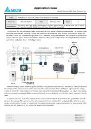
3.6 Artificial Fishpond Water Level Monitoring System (Flashing Circuit)<br />
X3<br />
X2<br />
X1<br />
X0<br />
Control Purpose:<br />
Devices:<br />
Y0<br />
Y1<br />
Y2<br />
Y3<br />
Y4<br />
X4<br />
RESET<br />
Feeding or draining water automatically when the water level <strong>of</strong> artificial fishpond is not at<br />
the normal level. In addition to feeding / draining water, enabling the alarm and alarm lamp<br />
when the water is above or below the alarm level.<br />
Stopping the alarm when RESET is pressed.<br />
X0<br />
Y3/Y4<br />
500ms<br />
500ms<br />
Device Function<br />
Alarm<br />
Alarm Lamp<br />
X0 X0 = ON when the water is above the lowest level <strong>of</strong> alarm level.<br />
X1 X1 = ON when the water is above the lowest level <strong>of</strong> normal level.<br />
X2 X2 = ON when the water is above the highest level <strong>of</strong> normal level.<br />
X3 X3 = ON when the water is above the highest level <strong>of</strong> alarm level.<br />
X4 X4 = ON when RESET is pressed.<br />
T1 500ms timer. Time base: 100ms.<br />
T2 500ms timer. Time base: 100ms.<br />
Y0 1# drainage pump<br />
Y1 Feeding pump<br />
Y2 2# drainage pump<br />
Y3 Alarm lamp<br />
Y4 Alarm<br />
3-7
3. Timer Design <strong>Examples</strong><br />
Control Program:<br />
3-8<br />
X3<br />
X1<br />
X2<br />
X0 T2<br />
X3<br />
T1<br />
X0 T1 X4<br />
X3<br />
RESET<br />
Y0<br />
Y1<br />
Y2<br />
TMR T1 K5<br />
TMR T2 K5<br />
Y3<br />
Y4<br />
Alarm Lamp<br />
Alarm<br />
Flashing Circuit<br />
Program Description:<br />
When the water is at normal level: X0 = ON, X1 = ON, X2 = OFF and X3 = OFF. Therefore,<br />
Y0 and Y2 will be OFF. Both the drainage pump and the feeding pump will not work.<br />
When the water is lower than the normal level, X0 = ON, X1 = OFF, X2 = OFF and X3 = OFF.<br />
Because X1 = OFF, Y1 will be ON. The feeding pump will start working.<br />
When the water is below the lowest <strong>of</strong> alarm level, X0 = OFF, X1= OFF, X2 = OFF and X3 =<br />
OFF. Because X1 = OFF, Y1 will be ON. The feeding pump will start working. In addition,<br />
because X0 = OFF, the flashing circuit will be activated, which makes Y3 = ON and Y4 = ON,<br />
The alarm lamp will flash and the alarm will ring.<br />
When the water is above the normal level, X0 = ON, X1 = ON, X2 = ON, X3 = OFF. Because<br />
X2 = ON, Y2 will be ON. 2# drainage pump will drain water from the fishpond.<br />
When the water is above the highest <strong>of</strong> alarm level, X0 = ON, X1 = ON, X2 = ON, X3 = ON.<br />
Because X2 = ON, Y2 will be ON. 2# drainage pump will work. In addition, because X3 = ON,<br />
Y0 will be ON. 2# drainage pump will work. Besides, the alarm circuit will be executed,<br />
which makes Y3 = ON and Y4 = ON. The alarm lamp will flash and the alarm will ring.<br />
When Reset is pressed, the NC contact X4 will be activated. Y3 = OFF and Y4 = OFF. Both<br />
the alarm and the alarm lamp will stop working.<br />
<strong>DVP</strong>-<strong>PLC</strong> <strong>Application</strong> <strong>Examples</strong>
3.7 Burn-in Test System (Timing Extension)<br />
Control Purpose:<br />
Devices:<br />
<strong>DVP</strong>-<strong>PLC</strong> <strong>Application</strong> <strong>Examples</strong><br />
Y0<br />
3. Timer Design <strong>Examples</strong><br />
Warning the operator to take out <strong>PLC</strong> from the burn-in room by the test completed indicator<br />
after 2.5 hours burn-in process.<br />
X0<br />
T0<br />
T1<br />
T2<br />
Y0<br />
3000 s<br />
3000 s<br />
3000 s<br />
(3000+3000+3000)s<br />
Device Function<br />
X0 When X0 = ON, the burn-in test starts<br />
T0 3,000 sec timer. Time base: 100ms<br />
T1 3,000 sec timer. Time base: 100ms<br />
T2 3,000 sec timer. Time base: 100ms<br />
Y0 Burn-in test completed indicator<br />
X0<br />
3-9
3. Timer Design <strong>Examples</strong><br />
Control Program:<br />
3-10<br />
X0<br />
T0<br />
T1<br />
T2<br />
Program Description:<br />
TMR<br />
TMR<br />
TMR<br />
Y0<br />
T0<br />
T1<br />
TT2<br />
K30000<br />
K30000<br />
K30000<br />
The upper bound value for a 16-bit timer is 100ms × 32767 = 3276.7s, so it needs several<br />
timers to work together for a timing extension application which is more than 1 hour (3600<br />
sec.) The total time is the sum <strong>of</strong> each timer’s set value.<br />
When the burn in test is started, X0 = ON. The timer T0 will start to count for 100ms × 30000<br />
= 3000sec. When T0 reaches its set value, the NO contact T0 will be ON and T1 will start to<br />
count for another 100ms × 30000 = 3000sec. When T1 reaches its set value, T2 will count<br />
one more 3000 sec and turn on the NO contact T2. Finally, the burn-in test completed<br />
indicator Y0 will be ON. The total time <strong>of</strong> the test is 3000s + 3000s + 3000s = 9000s =<br />
150min = 2.5h.<br />
The timing extension function can also be performed by using API 169 HOUR instruction.<br />
<strong>DVP</strong>-<strong>PLC</strong> <strong>Application</strong> <strong>Examples</strong>
3.8 Star-<strong>Delta</strong> Reduced Voltage Starter Control<br />
Control Purpose:<br />
<strong>DVP</strong>-<strong>PLC</strong> <strong>Application</strong> <strong>Examples</strong><br />
KM0<br />
KM1<br />
M<br />
3. Timer Design <strong>Examples</strong><br />
KM2<br />
Reduced Voltage Starting Main Circuit<br />
24V<br />
24G<br />
SS<br />
X0<br />
X1<br />
Y0<br />
Y1<br />
Y2<br />
COM<br />
<strong>PLC</strong> External Wiring<br />
Usually the starting current <strong>of</strong> the three-phase AC asynchronous motor is 5 ~7 times larger<br />
than the rated current. To reduce the effect <strong>of</strong> the starting current on the electrified wire<br />
fence, a star-delta reduced voltage starter should be applied.<br />
Starting process <strong>of</strong> a star-delta reduced voltage starter:<br />
When the switch is turned on, the contactors <strong>of</strong> both motor starter and “Star Reduced<br />
Voltage Starter” will be enabled first. After a 10 sec delay, the contactor <strong>of</strong> “Star Reduced<br />
Voltage Starter” will be disabled. Finally, the contactor <strong>of</strong> “<strong>Delta</strong> Reduced Voltage Starter”<br />
will be enabled after 1 sec, which operates the main motor circuit normally. The control<br />
purpose in this process is to assure the contactor <strong>of</strong> “Star Reduced Voltage Starter” is<br />
disabled completely before the contactor <strong>of</strong> “<strong>Delta</strong> Reduced Voltage Starter” is enabled.<br />
Devices:<br />
Device Function<br />
KM0<br />
KM2<br />
X0 X0 = ON when START is pressed.<br />
X1 X1 = ON when STOP is pressed.<br />
T1 10 sec timer. Time base: 100ms<br />
T2 1 sec timer. Time base: 100ms<br />
Y0 Motor starting contactor KM0<br />
Y1 “Star Reduced Voltage Starter” contactor KM1<br />
Y2 “<strong>Delta</strong> Reduced Voltage Starter” conntactor KM2<br />
3-11
3. Timer Design <strong>Examples</strong><br />
Control Program:<br />
3-12<br />
X0<br />
Y0<br />
X1<br />
Y0 T0 Y2<br />
Y1 T0<br />
T1 Y1 X1<br />
Y2<br />
Program Description:<br />
Y0<br />
TMR T0 K100<br />
Y1<br />
TMR T1 K10<br />
Y2<br />
X0 = ON when START is pressed. Y0 will be ON and latched. The motor starting contactor<br />
KM0 will be ON and the timer T0 will start to count for 10 sec. At the same time, because Y0<br />
= ON, T0 = OFF and Y2 = OFF, Y1 will be ON. The “Star Reduced Voltage Starter” contactor<br />
KM1 will be activated.<br />
When timer T0 reaches its set value, T0 will be ON and Y1 will be OFF. Timer T1 will start to<br />
count for 1 sec. After 1 sec, T1 = ON and Y2 = ON. “<strong>Delta</strong> Reduced Voltage Starter”<br />
contactor KM2 will be activated.<br />
X1 = ON when STOP is pressed. Y0, Y1 and Y2 will be OFF and the motor will stop running<br />
no matter it is in starting mode or running mode.<br />
<strong>DVP</strong>-<strong>PLC</strong> <strong>Application</strong> <strong>Examples</strong>
3.9 Automatic Door Control<br />
<strong>DVP</strong>-<strong>PLC</strong> <strong>Application</strong> <strong>Examples</strong><br />
X0(Infrared Sensor.)<br />
3. Timer Design <strong>Examples</strong><br />
X2(Opening Limit Switch) X1(Closing Limit Switch) X2(Opening Limit Switch)<br />
Control Purpose:<br />
Devices:<br />
Y0(Open the door)<br />
Y1(Close the door)<br />
When someone enters the infrared sensing field, opening motor starts working to open the<br />
door automatically till the door touches the opening limit switch<br />
If the door touches the opening limit switch for 7 sec and nobody enters the sensing field,<br />
the closing motor starts working to close the door automatically till the closing limit switch<br />
touched together.<br />
Stop the closing action immediately if someone enters the sensing field during the door<br />
closing process.<br />
Device Function<br />
X0 X0 = ON when someone enters the sensing field.<br />
X1 Closing limit switch. X1 = ON when 2 switches touched together.<br />
X2 Opening limit switch. X2 = ON when the door touched the switches.<br />
T0 7 sec timer. Time base: 100ms<br />
Y0 Opening motor<br />
Y1 Closing motor<br />
3-13
3. Timer Design <strong>Examples</strong><br />
Control Program:<br />
3-14<br />
X0 X2 Y1<br />
Y0<br />
X2 X0<br />
T0 X0 X1 Y0<br />
Y1<br />
Program Description:<br />
Y0<br />
TMR T0 K70<br />
Y1<br />
X0 = ON if someone enters the sensing field <strong>of</strong> the infrared sensor. Y0 will be ON and<br />
latched, and the door will be opened as long as the opening limit switches X2 = OFF.<br />
When the door touches the opening limit switches, X2 = ON. The timer T0 will start to count<br />
for 7 sec if no one enters the sensing field (X0 = OFF). After 7 sec., Y1 will be ON and<br />
latched and the door will be closed.<br />
During the closing process, X0 = ON if someone enters the sensing field. The NC contact<br />
X0 will be activated to turn Y1 <strong>of</strong>f. Because X0 = ON, X2 = OFF and Y1 = OFF, Y0 will be<br />
ON and the door will be opened once again.<br />
<strong>DVP</strong>-<strong>PLC</strong> <strong>Application</strong> <strong>Examples</strong>
3.10 Automatic Liquids Mixing Control System<br />
X2<br />
X1<br />
Control Purpose:<br />
Devices:<br />
<strong>DVP</strong>-<strong>PLC</strong> <strong>Application</strong> <strong>Examples</strong><br />
Y3<br />
Y0 ( Liquid A Inlet)<br />
Y1( Liquid B Inlet)<br />
Y2(Mixture Outlet)<br />
3. Timer Design <strong>Examples</strong><br />
X0<br />
START<br />
X1<br />
STOP<br />
X10<br />
EMERGENCY STOP<br />
Automatically infusing the container with liquids A and B in order when START is pressed.<br />
When it reaches the set level, mix the two liquids evenly then open the valve to let out the<br />
mixture.<br />
Device Function<br />
X0 X0 = ON when START is pressed.<br />
X1 Low level float sensor. X1 = ON when the liquid level reaches X1.<br />
X2 High level float sensor. X2 = ON when the liquid level reaches X2.<br />
X10 EMERGENCY STOP button. X10 = ON when the button is pressed.<br />
T0 60 sec timer. Time base: 100ms<br />
T1 120 sec timer. Time base: 100ms<br />
Y0 Liquid A inlet<br />
Y1 Liquid B inlet<br />
Y2 Mixture outlet<br />
Y3 Agitator<br />
3-15
3. Timer Design <strong>Examples</strong><br />
Control Program:<br />
3-16<br />
X0 X1 X10<br />
Y0<br />
X1 X2 X10<br />
Y1<br />
X2 T0 X10<br />
T0 T1 X10<br />
Y2<br />
Y2<br />
Program Description:<br />
Y0<br />
Y1<br />
Y3<br />
TMR T0 K600<br />
Y2<br />
TMR T1 K1200<br />
X0 = ON when START is pressed. Y0 will be ON and latched, and the valve will be opened<br />
for infusing liquid A until the level reaches the low-level float sensor.<br />
X1 = ON when the level reaches the low-level float sensor. Y1 will be ON and latched, and<br />
the valve will be opened for infusing liquid B until the level reaches the high-level float<br />
sensor.<br />
X2 = ON when the level reaches the high-level float sensor. Y3 will be ON and activates the<br />
agitator. Also, timer T0 will start to count for 60 sec. After 60 sec, T0 will be ON, and the<br />
agitator motor Y3 will stop working. Y2 will be ON and latched, and the mixture will drain out<br />
<strong>of</strong> the container.<br />
When Y2 = ON, timer T1 will start to count for 120 sec. After 120 sec, T1 will be ON and Y2<br />
will be OFF. The draining process will be stopped.<br />
When an error occurs, press EMERGENCY STOP button X10. The NC contact X10 will be<br />
ON to disable all the outputs. The system will then stop running.<br />
<strong>DVP</strong>-<strong>PLC</strong> <strong>Application</strong> <strong>Examples</strong>
3.11 Automatic C<strong>of</strong>fee Maker<br />
Control Purpose:<br />
Devices:<br />
Control Program:<br />
<strong>DVP</strong>-<strong>PLC</strong> <strong>Application</strong> <strong>Examples</strong><br />
X0<br />
Coin Detector<br />
Y0<br />
Paper Cup Outlet<br />
C<strong>of</strong>fee 咖啡<br />
Hot 热水 Water<br />
Y1 Y2<br />
Mixing Container<br />
X1 X2<br />
X1<br />
Y4<br />
3. Timer Design <strong>Examples</strong><br />
Making the paper cup come out <strong>of</strong> the outlet when a coin is inserted. At the same time, the<br />
c<strong>of</strong>fee pours in the mixing container. After 2 sec, the hot water pours in. 60 sec later, the<br />
ready-made c<strong>of</strong>fee will be pouring out from the c<strong>of</strong>fee outlet.<br />
X0<br />
Y0<br />
Device Function<br />
X0 Coin detector. X0 = ON when a coin is inserted.<br />
X1<br />
Pressure detector. X1 = ON when the liquid in the container reaches a certain<br />
amount <strong>of</strong> pressure.<br />
T0 2 sec timer. Time base: 100ms<br />
T1 60 sec timer. Time base: 100ms<br />
Y0 Paper cup outlet<br />
Y1 C<strong>of</strong>fee outlet<br />
Y2 Hot water outlet<br />
Y3 Agitator<br />
Y4 Ready-made c<strong>of</strong>fee outlet<br />
Y1 T0<br />
SET Y0<br />
SET Y1<br />
Y3<br />
TMR T0 K20<br />
3-17
3. Timer Design <strong>Examples</strong><br />
3-18<br />
T0<br />
X1<br />
T1<br />
X1<br />
Program Description:<br />
T1<br />
SET Y2<br />
RST<br />
RST<br />
Y0<br />
Y1<br />
RST Y2<br />
SET<br />
Y3<br />
TMR T1 K600<br />
SET Y4<br />
RST Y3<br />
RST Y4<br />
X1 = ON when a coin is inserted. Y0 and Y1 will be ON and latched. A paper cup will be sent<br />
out, and a certain amount <strong>of</strong> c<strong>of</strong>fee will be poured into the container at the same time.<br />
Y0 and Y1 will be ON for 2 sec which is the set value <strong>of</strong> timer T0. When NO contact T0 is<br />
ON, Y2 will be activated and the hot water will be poured in the container. At the same time,<br />
the outlets <strong>of</strong> both paper cup and c<strong>of</strong>fee will be closed.<br />
When the liquid in the container reaches a certain amount <strong>of</strong> pressure, X1 = ON. Therefore,<br />
the hot water outlet Y2 will be reset, and the agitator Y3 will be ON for 60 sec. After 60 sec,<br />
NO contact T1 will be ON. Y4 will be ON and latched, and Y3 will be reset at the same time.<br />
The agitator will stop working, and the ready-made c<strong>of</strong>fee will be pouring out from the outlet.<br />
When the c<strong>of</strong>fee is poured into the paper cup completely, X1 will be OFF and Y4 will be<br />
reset. The ready-made c<strong>of</strong>fee outlet will be closed.<br />
<strong>DVP</strong>-<strong>PLC</strong> <strong>Application</strong> <strong>Examples</strong>
3.12 Automatic Urinal Flushing Control Program<br />
Control Purpose:<br />
X0<br />
Y0<br />
Devices:<br />
<strong>DVP</strong>-<strong>PLC</strong> <strong>Application</strong> <strong>Examples</strong><br />
3. Timer Design <strong>Examples</strong><br />
If a user stands in front <strong>of</strong> the urinal for more than 3 sec, the flushing control device will flush<br />
the urinal for 3 sec (the first flushing). When the user leaves the urinal, flush for another 4<br />
sec then stop automatically (the second flushing).<br />
X0<br />
Y0<br />
3s<br />
Standing time<br />
3s 4s<br />
The first flushing The second flushing<br />
Stopping the first flushing and starting the second flushing if the first user leaves the urinal<br />
during the first flushing process.<br />
X0<br />
Y0<br />
The first user<br />
3s<br />
The first flushing<br />
3s<br />
4s<br />
Standing time<br />
The second flushing<br />
If the second user comes before the finishing <strong>of</strong> the 4 sec flushing, the flusher will finish the<br />
4 sec flushing process and skip the first 3 sec flushing process. When the second user<br />
leaves the urinal, the flusher will perform another 4 sec flushing.<br />
The first user The second user<br />
3s 3s 4s<br />
Standing time The first flushing The second flushing The second flushing<br />
Device Function<br />
X0 Infrared sensor. X0 = ON when a user is detected.<br />
M0 ~ M2 Internal auxiliary relay<br />
T0 3 sec timer. Time base: 100ms<br />
T1 3 sec timer. Time base: 100ms<br />
T2 4 sec timer. Time base: 100ms<br />
Y0 Flushing valve<br />
4s<br />
3-19
3. Timer Design <strong>Examples</strong><br />
Control Program:<br />
3-20<br />
X0<br />
X0 Y0<br />
T0<br />
M0 M2<br />
X0<br />
M1<br />
M0<br />
M0 T1 M2<br />
X0 M0 T2<br />
M1<br />
X0<br />
Program Description:<br />
T2<br />
TMR T0 K30<br />
SET M2<br />
SET M0<br />
TMR T1 K30<br />
M1<br />
TMR T2 K40<br />
ZRST M0 M1<br />
Y0<br />
RST M2<br />
When a user is detected, infrared sensor X0 will be ON. In this case, T0 will be ON and start<br />
to count for 3 sec. If the user leaves in 3 sec, X0 = OFF, and T0 will be OFF. No action will be<br />
performed. If the user stands for more than 3 sec, the NO contact T0 will be activated, which<br />
turns on M0. The first flushing will start (Y0 = ON).<br />
M1 is latched in this program. If the user leaves after 3 sec, which means the NO contact M0<br />
= ON and the NC contact X0 is OFF, M1 will be ON and latched. The second flushing will<br />
then be started. After 4 sec, both the NO contact and the NC contact <strong>of</strong> T2 will be activated.<br />
Therefore, Y0 will be OFF, and the flushing will be stopped. M0 and M1 will be reset.<br />
Because M1 is latched, the second flushing process will certainly be executed whether X0<br />
changes its state or not.<br />
<strong>DVP</strong>-<strong>PLC</strong> <strong>Application</strong> <strong>Examples</strong>
3.13 Performing Accumulative Function with Normal Timer<br />
X0<br />
Control Purpose:<br />
Devices:<br />
Control Program:<br />
GO<br />
Y0<br />
<strong>DVP</strong>-<strong>PLC</strong> <strong>Application</strong> <strong>Examples</strong><br />
3. Timer Design <strong>Examples</strong><br />
X1<br />
Car Washer<br />
Ensuring that the customers wash their cars for entire 5 minutes no matter how many times<br />
the sprayer valve stops. .<br />
Device Function<br />
X0 Sprayer valve switch. X0 = ON when the sprayer handle is held on tightly.<br />
X1 Coin detector. X1 = ON when an inserted coin is detected.<br />
M1 Creating a trigger pulse for one program scan cycle<br />
T1 Timer. Time base: 100ms<br />
D10 Storing present value <strong>of</strong> T1<br />
Y0 Sprayer valve<br />
X0<br />
X1<br />
M1<br />
T1<br />
PLS M1<br />
MOV D10 T1<br />
TMR T1 K3000<br />
MOV T1 D10<br />
Y0<br />
MOV K0 D10<br />
3-21
3. Timer Design <strong>Examples</strong><br />
Program Description:<br />
3-22<br />
When customers insert coins in the slot, X1 = ON. The time value <strong>of</strong> D10 will be cleared.<br />
When customers compress the sprayer handle, X0 = ON. PLS instruction will be executed.<br />
M1 will be ON for one program scan cycle, which starts T1 to count from 0 to 5 min (T1 =<br />
K3000). In this case, Y0 = ON, and the sprayer valve is open.<br />
If the sprayer handle is released, the timer will stop counting. The present value in the timer<br />
will be saved and the water spraying will be interrupted.<br />
When customers compress the sprayer handle again, the timer will start to count from the<br />
value saved in D10. Because the present value <strong>of</strong> T1 is sent to D10 and saved when T1 is<br />
working, the saved value will be sent to T1 as its present value when T1 is activated again.<br />
Therefore, even if there are some interruptions <strong>of</strong> the sprayer valve in the washing process,<br />
the program assures customers <strong>of</strong> entire 5 minutes car washing service.<br />
<strong>DVP</strong>-<strong>PLC</strong> <strong>Application</strong> <strong>Examples</strong>
3.14 Performing Teaching Function with Normal Timer<br />
Control Purpose:<br />
Devices:<br />
<strong>DVP</strong>-<strong>PLC</strong> <strong>Application</strong> <strong>Examples</strong><br />
3. Timer Design <strong>Examples</strong><br />
X0 X2 X3 X1<br />
Teach Start<br />
Manual Auto<br />
In Manual mode, the engineers should adjust stamping time according to their experience.<br />
The stamping time depends on the time <strong>of</strong> pressing Teach.<br />
In Auto mode, if Start is pressed, the machine will perform stamping process once according<br />
to the time value saved by Teach process.<br />
Device Function<br />
X0 Teach Button. X0 = ON when the button Teach is pressed.<br />
X1 Start button. X1 = ON when the button Start is pressed.<br />
X2 Manual mode<br />
X3 Auto mode<br />
M1 Start trigger in auto mode<br />
T0 Timer. Time base: 100ms<br />
T1 Timer. Time base: 100ms<br />
D0 Data register. Saving the time value <strong>of</strong> stamping<br />
Y0 Starting the punch when Teach is pressed<br />
Y1 Starting the punch when Start is pressed in Auto mode<br />
3-23
3. Timer Design <strong>Examples</strong><br />
Control Program:<br />
3-24<br />
X0<br />
X1<br />
M1<br />
T1<br />
Program Description:<br />
X2 X3<br />
X2 X3<br />
T1<br />
TMR T0 K32767<br />
TMR T0 D0<br />
Y0<br />
SET<br />
TMR T1<br />
X2 = ON when the switch is turned to Manual mode. X0 = ON when Teach is pressed. In this<br />
case, coil Y0 will be ON and start the stamping process. At the same time, T0 will be<br />
executed and its present value will be sent to D0. Release the button Teach when the<br />
stamping process is completed. Y0 will be OFF, and the stamping process will be stopped.<br />
X3 = ON when the switch is turned to Auto mode. Each time when X1 is pressed, Y1 will be<br />
ON and the stamping process will be executed. At the same time, T1 will be activated to<br />
count until it achieves the target value (the saved value in T0). When the stamping time is<br />
achieved, the NC contact T1 and the rising edge trigger T1 will be activated and enable both<br />
M1 and Y1 to be OFF. The stamping process will thus be stopped. When the button Start is<br />
pressed again, M1 will be ON and repeats the same stamping process.<br />
The timer teaching function can also be performed by using API 64 TTMR instruction.<br />
Y1<br />
RST<br />
M1<br />
M1<br />
D0<br />
<strong>DVP</strong>-<strong>PLC</strong> <strong>Application</strong> <strong>Examples</strong>
3.15 Auto Interruption Timer<br />
Control Purpose:<br />
Devices:<br />
Control Program:<br />
Production Line 1<br />
Production Line 2<br />
3. Timer Design <strong>Examples</strong><br />
In <strong>PLC</strong> production lines, an operator should be in charge <strong>of</strong> packing products on two<br />
conveyor belts into 2 boxes. For ensuring that operators have sufficient time for packing, the<br />
program is designed to control two conveyor belts to be running alternatively: stops one<br />
conveyor after 30 sec running and then starts another conveyor for 30 sec running.<br />
T0<br />
T0<br />
M0<br />
<strong>DVP</strong>-<strong>PLC</strong> <strong>Application</strong> <strong>Examples</strong> 3-25<br />
Y0<br />
Y1<br />
Device Function<br />
T0 30 sec timer. Time base: 100ms<br />
M0 Controlling the trigger circuit<br />
M1 Alternating the conveyor belt<br />
Y0 Executing the production line 1<br />
Y1 Executing the production line 2<br />
M1<br />
M0 M1<br />
M1<br />
M1<br />
TMR T0 K300<br />
M0<br />
M1<br />
Y0<br />
Y1<br />
Trigger Circuit
3. Timer Design <strong>Examples</strong><br />
Program Description:<br />
3-26<br />
This program uses the NC contact T0 as the executing condition <strong>of</strong> the timer T0. When T0<br />
reaches its set value, 30 sec, it will be activated. The trigger circuit will be executed to<br />
change the state <strong>of</strong> M1. Production line 1 will then start working.<br />
After 30 sec counting, T0 turns ON. The NC contact T0 will be activated. At the same time,<br />
timer T0 will thus be OFF, which makes the NC contact T0 to be OFF again. In the next scan<br />
period, because the NC contact T0 is OFF, timer T0 will start counting. After 30 sec counting,<br />
T0 will be activated and so will the trigger circuit. In this case, M1 changes its state again.<br />
Production line 1 will be stopped and production line 2 will start working.<br />
By using the trigger circuit to activate Y0 and Y1 alternatively, the program makes the two<br />
production lines to convey products alternatively.<br />
<strong>DVP</strong>-<strong>PLC</strong> <strong>Application</strong> <strong>Examples</strong>
3.16 Interesting Fountain<br />
Control Purpose:<br />
Devices:<br />
Control Program:<br />
3. Timer Design <strong>Examples</strong><br />
Y0 X0<br />
Keeping the Running indicator in ON state when the Start button is pressed.<br />
Enabling the following devices to start in order after Running indicator is ON for 2 sec:<br />
middle sprayer light > middle sprayer valve > surrounding lights > surrounding sprayer<br />
valves. Each <strong>of</strong> them will be ON for 2 sec.<br />
X0<br />
X0<br />
Device Function<br />
X0 X0 = ON when the Start button <strong>of</strong> the fountain is pressed.<br />
T0 2 sec timer. Time base: 100ms<br />
T1 2 sec timer. Time base: 100ms<br />
T2<br />
T3<br />
T4<br />
2 sec timer. Time base: 100ms<br />
2 sec timer. Time base: 100ms<br />
2 sec timer. Time base: 100ms<br />
Y0 Running indicator <strong>of</strong> the fountain<br />
Y1 Middle sprayer light<br />
Y2 Middle sprayer valve<br />
Y3 Surrounding lights<br />
Y4 Surrounding sprayer valves<br />
Y0 Y1 Y2 Y3 Y4<br />
T0<br />
T4<br />
Y0<br />
ZRST Y1 Y4<br />
TMR T0<br />
SET Y1<br />
Running indicator <strong>of</strong> the fountain<br />
<strong>DVP</strong>-<strong>PLC</strong> <strong>Application</strong> <strong>Examples</strong> 3-27<br />
K20<br />
The Running indicator works<br />
for 2 sec.
3. Timer Design <strong>Examples</strong><br />
3-28<br />
Y1 Y2 Y3 Y4<br />
T1<br />
Y2 Y3 Y4<br />
T2<br />
Y3 Y4<br />
T3<br />
Y4<br />
T4<br />
Program Description:<br />
TMR<br />
SET Y2<br />
RST Y1<br />
TMR<br />
SET Y3<br />
RST Y4<br />
TMR<br />
SET Y4<br />
RST Y3<br />
TMR<br />
RST Y4<br />
T1 K20<br />
T2 K20<br />
T3 K20<br />
T4 K20<br />
The middle sprayer light<br />
works for 2 sec.<br />
The middle sprayer valve<br />
works for 2 sec.<br />
The surrounding lights work for 2 sec.<br />
The surrounding sprayer valves<br />
work for 2 sec.<br />
X0 = ON when the button Start is pressed. Coil Y0 will be ON to activate the Running<br />
indicator. Y0 = ON is used as the executing condition for the timer T0. After 2 sec counting<br />
down, T0 goes from OFF to ON and executes [SET Y1] instruction. The middle sprayer light<br />
Y1 will be ON. The Running indicator Y0 will be kept in ON state through the whole working<br />
process.<br />
Likewise, Y1 = ON is used as the executing condition for the timer T1, and so does Y2 = ON<br />
for the timer T2 as well as Y3 = ON for the timer T3. The executions will be assured in the<br />
following order: Y1, Y2, Y3, and Y4.<br />
The middle sprayer light, middle sprayer valve, surrounding lights, and surrounding sprayer<br />
valves need to be started in order. Therefore, when T1, T2 and T3 go from OFF to ON and<br />
set the next execution, they also reset the present execution. In addition, the NC contacts <strong>of</strong><br />
Y1, Y2, Y3 and Y4 are used for turning <strong>of</strong>f timers T0, T1, T2 and T3.<br />
After the completion <strong>of</strong> the last execution, the rising edge switch T4 will reset Y4 and set Y1.<br />
The second round <strong>of</strong> fountain display will then be started again.<br />
When X0 = OFF, coil Y0 will be OFF to turn <strong>of</strong>f the Running indicator. In addition, ZRST<br />
instruction will be executed at the same time. Y1, Y2, Y3 and Y4 will be reset and all the<br />
valves and lights in the fountain will be stopped immediately.<br />
<strong>DVP</strong>-<strong>PLC</strong> <strong>Application</strong> <strong>Examples</strong>
3.17 Traffic Lights Control<br />
Control Purpose:<br />
3. Timer Design <strong>Examples</strong><br />
North-South Direction<br />
East-West Direction<br />
Enabling the traffic lights to work by Start button X0 and to stop by Stop button X1.<br />
Setting the time <strong>of</strong> red light in East-West direction as 60 sec and North-South direction with<br />
a heavier traffic as 30 sec.<br />
The time <strong>of</strong> red light in East-West direction equals to the time <strong>of</strong> “green light + green light<br />
flashing + yellow light” in North-south direction, and vice versa.<br />
When yellow light is ON, cars and pedestrians should not cross the road, and yellow light<br />
will last for 5 sec for the crossing cars and pedestrians to pass safely.<br />
Timing diagram <strong>of</strong> traffic lights in East-West direction:<br />
Red (Y0)<br />
Green (Y1)<br />
Yellow (Y2)<br />
60 s<br />
<strong>DVP</strong>-<strong>PLC</strong> <strong>Application</strong> <strong>Examples</strong> 3-29<br />
20 s<br />
Timing diagram <strong>of</strong> traffic lights in North-South direction:<br />
Red (Y10)<br />
Green (Y11)<br />
Yellow (Y12)<br />
30 s<br />
60 s<br />
5 s<br />
5 s<br />
5 s<br />
5 s
3. Timer Design <strong>Examples</strong><br />
Devices:<br />
Control Program:<br />
3-30<br />
Device Function<br />
X0 Start button<br />
X1 Stop button<br />
T0<br />
T1<br />
T2<br />
T10<br />
T11<br />
T12<br />
T13<br />
S0 Initial step<br />
60 sec timer. Time base: 100ms<br />
20 sec timer. Time base: 100ms<br />
5 sec timer. Time base: 100ms<br />
50 sec timer. Time base: 100ms<br />
5 sec timer. Time base: 100ms<br />
5 sec timer. Time base: 100ms<br />
30 sec timer. Time base: 100ms<br />
S10 ~ S13 Controlling the Traffic lights in East-West direction<br />
S20 ~ S23 Controlling the Traffic lights in North-South direction<br />
X0<br />
X1<br />
S0<br />
S<br />
S10<br />
S<br />
Y0 Red light in East-West direction<br />
Y1 Green light in East-West direction<br />
Y2 Yellow light in East-West direction<br />
Y10 Red light in North-South direction<br />
Y11 Green light in North-South direction<br />
Y12 Yellow light in North-South direction<br />
T0<br />
PLS<br />
PLS<br />
M0<br />
SET S0<br />
M1<br />
ZRST S0 S127<br />
SET S10<br />
SET S20<br />
Y0<br />
TMR T0<br />
SET S11<br />
K600<br />
Red light in East-West direction<br />
is ON for 60 sec.<br />
<strong>DVP</strong>-<strong>PLC</strong> <strong>Application</strong> <strong>Examples</strong>
S11<br />
S<br />
S12<br />
S<br />
Program Description:<br />
S13<br />
S<br />
Y2<br />
S20<br />
S Y11<br />
S21<br />
S<br />
S22<br />
S<br />
S23<br />
S<br />
T1<br />
M1013<br />
T2<br />
T10<br />
M1013<br />
T11<br />
T12<br />
S13 S23<br />
S S<br />
T13<br />
Y1<br />
TMR T1<br />
SET S12<br />
TMR T2<br />
Y1<br />
SET S13<br />
TMR T10<br />
SET S21<br />
TMR T11<br />
Y11<br />
SET S22<br />
Y12<br />
TMR<br />
SET<br />
Y10<br />
TMR<br />
S0<br />
RET<br />
3. Timer Design <strong>Examples</strong><br />
K500 Green light in North-South direction<br />
is ON for 50 sec.<br />
When Start is pressed, X0 = ON. PLS instruction will be executed, and M0 will create a<br />
rising-edge pulse to set T0. The program will enter the step ladder process.<br />
When Stop is pressed, X1 = ON. PLS instruction will be executed, and M1 will create a<br />
rising-edge pulse to execute [ZRST S0 S127] instruction. All steps will be reset and all traffic<br />
<strong>DVP</strong>-<strong>PLC</strong> <strong>Application</strong> <strong>Examples</strong> 3-31<br />
T12<br />
S23<br />
K200<br />
K50<br />
Yellow light in East-West direction<br />
is ON.<br />
K50<br />
K50<br />
T13 K300<br />
Green light in East-West direction<br />
is ON for 20 sec.<br />
Green light in East-West direction<br />
is flashing for 5 sec.<br />
Green light in North-South direction<br />
is flashing for 5 sec.<br />
Yellow light in North-South direction<br />
is ON for 5 sec.<br />
Red light in North-South direction<br />
is ON for 30 sec.
3. Timer Design <strong>Examples</strong><br />
3-32<br />
lights will be OFF.<br />
This example is designed by the application <strong>of</strong> the simultaneous divergence sequence. The<br />
two sequences running simultaneously are East-West direction and North-South direction.<br />
When the red light <strong>of</strong> East-West direction is ON, the corresponding state <strong>of</strong> North-South<br />
direction will be the sequence <strong>of</strong> “Green ON”, “Green Flashing” and “Yellow ON.”<br />
When the East-West direction sequence is finished (the yellow light is OFF), the<br />
North-South direction sequence will be finished as well (the red light is OFF). The program<br />
will return to the initial step S0.<br />
When a step is transferred from one sequence to another sequence, the former sequence<br />
will be reset including the step and output point Y.<br />
The time <strong>of</strong> yellow light in East-West direction (Y2) is not controlled by a timer because<br />
when the red light in North-South direction is OFF, the yellow light in North-South direction<br />
will be reset at the same time. In this case, T13 is ON to redirect the program to initial step<br />
S0, and the outputs (Y2 and Y10) corresponding to S13 and S23 will thus be reset.<br />
<strong>DVP</strong>-<strong>PLC</strong> <strong>Application</strong> <strong>Examples</strong>
4.1 Summation <strong>of</strong> Continuous D Registers<br />
Control Purpose:<br />
Devices:<br />
Control Program:<br />
4. Index Registers E, F Design <strong>Examples</strong><br />
Summing up the values <strong>of</strong> D registers from D101 to DN (the number <strong>of</strong> N is determined by<br />
users) and storing the operation result in D100. If the result < K-32768, the borrow flag = ON;<br />
if the result > K32767, the carry flag = ON.<br />
M1000<br />
M1000<br />
M1021<br />
M1022<br />
Program Description:<br />
Device Function<br />
Y0 Borrow flag indicator. When the value in D100 < K-32768, Y0 = ON<br />
Y1 Carry flag indicator. When the value in D100 > K32767, Y1 = ON<br />
E1 Index register<br />
D100 Storing the sum <strong>of</strong> all D registers<br />
D500 Storing the executing times <strong>of</strong> FOR-NEXT loop<br />
MOV K1 E1<br />
MOV K0 D100<br />
<strong>DVP</strong>-<strong>PLC</strong> <strong>Application</strong> <strong>Examples</strong> 4-1<br />
FOR<br />
INC<br />
D500<br />
ADD D100 D100E1 D100<br />
NEXT<br />
Y0<br />
Y1<br />
The key <strong>of</strong> the program is to use the index register E1 together with FOR ~ NEXT loop to<br />
vary the addend D100E1. When E1 = K1, D100E1 represents D101; when E1 = K2, D100E1<br />
represents D102. Also, when E1 = K10, D100E1 represents D110.<br />
The number <strong>of</strong> continuous D registers is determined by the execution times <strong>of</strong> FOR ~NEXT<br />
loop which is set by D500. If the value in D500 ≤ 1, the loop will execute 1 time. If the value<br />
in D500 = K10, the loop will execute 10 times first and then execute the instructions behind<br />
E1
4. Index Registers E, F Design <strong>Examples</strong><br />
4-2<br />
the loop.<br />
In the first FOR ~ NEXT loop, E1 = K1, so D100E1 represents D101. ADD instruction is<br />
executed, and the operation result <strong>of</strong> D100 plus D101 is stored in D100. Since the<br />
summand D100 = K0, the value stored in D100 equals to the value in D101. At the same<br />
time, INC instruction is executed to set E1 = K2.<br />
In the second FOR ~ NEXT loop, E1 = K2, so D100E1 represents D102. ADD instruction is<br />
executed, and the operation result <strong>of</strong> the values <strong>of</strong> D100 plus D102 is stored in D100. Since<br />
the summand D100 = D101, the value stored in D100 is the sum <strong>of</strong> the D101 and D102.<br />
According to the same process, by the 10 th FOR ~ NEXT loop the value in D100 will be the<br />
sum <strong>of</strong> D101, D102, D103, D104, D105, D106, D107, D108, D109 and D110.<br />
If the operation result < K-32768, M1021 will be ON to activate the output coil Y0. Borrow<br />
flag indicator will be ON. On the contrary, if the operation result > K32767, M1022 will be ON<br />
to activate output coil Y1. Carry flag indicator will be ON in this case.<br />
<strong>DVP</strong>-<strong>PLC</strong> <strong>Application</strong> <strong>Examples</strong>
4.2 Parameter Setting for Product Recipe<br />
Control Purpose:<br />
Devices:<br />
Control Program:<br />
4. Index Registers E, F Design <strong>Examples</strong><br />
For one product, there are 3 models which correspond to 3 sets <strong>of</strong> recipes. Each recipe<br />
includes 10 parameters. The program executes the set parameters according to the<br />
selected recipe switch.<br />
Device Function<br />
X0 Switch <strong>of</strong> the first recipe<br />
X1 Switch <strong>of</strong> the second recipe<br />
X2 Switch <strong>of</strong> the third recipe<br />
D500 ~ D509 Parameters <strong>of</strong> the first group<br />
D510 ~ D519 Parameters <strong>of</strong> the second group<br />
D520 ~ D529 Parameters <strong>of</strong> the third group<br />
D100 ~ D109 The present parameters<br />
X0<br />
X1<br />
X2<br />
X0<br />
X1<br />
X2<br />
M0<br />
M0<br />
LD>= F1 K10<br />
<strong>DVP</strong>-<strong>PLC</strong> <strong>Application</strong> <strong>Examples</strong> 4-3<br />
MOV<br />
MOV<br />
MOV<br />
RST<br />
RST<br />
FOR<br />
INC<br />
INC<br />
SET<br />
K500<br />
K510<br />
K520<br />
M0<br />
K10<br />
E1<br />
F1<br />
M0<br />
E1<br />
E1<br />
E1<br />
MOV D0E1 D100F1<br />
NEXT<br />
F1
4. Index Registers E, F Design <strong>Examples</strong><br />
Program Description:<br />
4-4<br />
The key to this program is to use index register E1, F1 together with FOR ~ NEXT loop to<br />
vary the numbers <strong>of</strong> D registers. In addition, the program transfers the parameters <strong>of</strong> the<br />
selected recipe to the register <strong>of</strong> present parameters<br />
When one recipe is selected, the corresponding switch X0, X1 or X2 will be ON. According<br />
to the selected value <strong>of</strong> E1, the number <strong>of</strong> register D0E1 would be D500, D510 or D520.<br />
[RST M0] will be executed to reset F1, and FOR ~ NEXT will be executed. Because F1 is<br />
reset as K0, D100F1 represents D100 in this case.<br />
The FOR ~ NEXT loop is executed for 10 times in this program. If the first recipe is selected,<br />
D0E1 will vary from D500 to D509 and D100F1 will vary from D100 to D109.<br />
In addition, the value <strong>of</strong> D500 will be sent to D100 in the first FOR ~ NEXT loop. The value<br />
<strong>of</strong> D501 will be sent to D101 in the second loop. By the same process, the value <strong>of</strong> D509 will<br />
be sent to D109 in the 10 th loop.<br />
When the executing time reaches its set value, which means F1 = K10, [SET M0] instruction<br />
will be executed. The Normally Closed contact M0 will be activated to stop FOR ~ NEXT<br />
loops.<br />
The program performs the transferring <strong>of</strong> 10 parameters <strong>of</strong> each recipe. The numbers <strong>of</strong><br />
parameters can easily be changed by setting the executing times <strong>of</strong> FOR ~ NEXT loop.<br />
Besides, if it requires adding more recipes, the program can also meet this requirement by<br />
adding one more MOV instruction as [MOV K530 E1].<br />
<strong>DVP</strong>-<strong>PLC</strong> <strong>Application</strong> <strong>Examples</strong>
4. Index Registers E, F Design <strong>Examples</strong><br />
4.3 Controlling Voltage Output <strong>of</strong> 2 <strong>DVP</strong>-04DA by 8 VRs (Variable Resistors)<br />
Control Purpose:<br />
Devices:<br />
Control Program:<br />
<strong>DVP</strong>-F6VR<br />
<strong>DVP</strong>-EH MPU<br />
<strong>DVP</strong>04DA<br />
<strong>DVP</strong>04DA<br />
Controlling the voltage output <strong>of</strong> 2 <strong>DVP</strong>-04DA to vary from 0 ~ 10V by adjusting 8 VRs on<br />
<strong>DVP</strong>-EH series <strong>PLC</strong> (2 VRs on the EH MPU and 6 VRs on <strong>DVP</strong>-F6VR extension unit).<br />
M1000<br />
X0<br />
Device Function<br />
X0 Start Switch <strong>of</strong> reading VR volume<br />
X1 Writing in the value <strong>of</strong> the first <strong>DVP</strong>04DA<br />
X2 Writing in the value <strong>of</strong> the second <strong>DVP</strong>04DA<br />
E0 Index register<br />
RST E0<br />
FOR<br />
INC<br />
<strong>DVP</strong>-<strong>PLC</strong> <strong>Application</strong> <strong>Examples</strong> 4-5<br />
K8<br />
VRRD K0@E0 D0E0<br />
NEXT<br />
E0<br />
Reading out values <strong>of</strong> 8<br />
VRs in order by [INC E0]<br />
and FOR ~ NEXT loop
4. Index Registers E, F Design <strong>Examples</strong><br />
4-6<br />
X0<br />
X0<br />
X0<br />
X0<br />
X0<br />
X0<br />
X0<br />
X0<br />
X0<br />
X0<br />
X0<br />
X0<br />
X0<br />
X0<br />
MOV<br />
MOV<br />
MOV<br />
MOV<br />
MOV<br />
MOV<br />
MOV<br />
MOV<br />
DMUL<br />
DDIV<br />
DMUL<br />
DDIV<br />
DMUL<br />
DDIV<br />
DMUL<br />
DDIV<br />
DMUL<br />
DDIV<br />
DMUL<br />
DDIV<br />
D0<br />
D1<br />
D2<br />
D3<br />
D4<br />
D5<br />
D6<br />
D7<br />
D10<br />
D100<br />
D20<br />
D110<br />
D30<br />
D120<br />
D40<br />
D130<br />
D50<br />
D140<br />
D60<br />
D150<br />
D10<br />
D20<br />
D30<br />
D40<br />
D50<br />
D60<br />
D70<br />
D80<br />
K4000<br />
K255<br />
K4000<br />
K255<br />
K4000<br />
K255<br />
K4000<br />
K255<br />
K4000<br />
K255<br />
K4000<br />
K255<br />
Sending the data in<br />
D0 ~ D7 to D10 ~ D80<br />
according ly<br />
D100<br />
D200<br />
D110<br />
D210<br />
D120<br />
D220<br />
D130<br />
D230<br />
D140<br />
D240<br />
D150<br />
D250<br />
Read out value<br />
processing <strong>of</strong><br />
the 1st VR<br />
Read out value<br />
processing <strong>of</strong><br />
the 2nd VR<br />
Read out value<br />
processing <strong>of</strong><br />
the 3rd VR<br />
Read out value<br />
processing <strong>of</strong><br />
the 4th VR<br />
Read out value<br />
processing <strong>of</strong><br />
the 5th VR<br />
Read out value<br />
processing <strong>of</strong><br />
the 6st VR<br />
<strong>DVP</strong>-<strong>PLC</strong> <strong>Application</strong> <strong>Examples</strong>
X0<br />
X0<br />
X1<br />
X2<br />
Program Description:<br />
4. Index Registers E, F Design <strong>Examples</strong><br />
DMUL<br />
DDIV<br />
DMUL<br />
DDIV<br />
TO<br />
TO<br />
TO<br />
TO<br />
TO<br />
TO<br />
TO<br />
TO<br />
D70<br />
D160<br />
D80<br />
D170<br />
K0<br />
K0<br />
K0<br />
K0<br />
K1<br />
K1<br />
K1<br />
K1<br />
K4000<br />
K4000<br />
<strong>DVP</strong>-<strong>PLC</strong> <strong>Application</strong> <strong>Examples</strong> 4-7<br />
K255<br />
K255<br />
K6<br />
K7<br />
K8<br />
K9<br />
K6<br />
K7<br />
K8<br />
K9<br />
D160<br />
D260<br />
D170<br />
D270<br />
D200<br />
D210<br />
D220<br />
D230<br />
D240<br />
D250<br />
D260<br />
D270<br />
Read out value<br />
processing <strong>of</strong><br />
the 7th VR<br />
Read out value<br />
processing <strong>of</strong><br />
the 8th VR<br />
K1<br />
K1<br />
K1<br />
K1<br />
K1<br />
K1<br />
K1<br />
K1<br />
Controlling<br />
0 ~10V output<br />
from 4 channels<br />
on the 1st DA<br />
module<br />
Controlling<br />
0 ~10V output<br />
from 4 channels<br />
on the 2nd DA<br />
module<br />
The program uses index register E0 and FOR ~ NEXT loop to specify the No. <strong>of</strong> VR as well<br />
as the No. <strong>of</strong> D registers which store the read out value <strong>of</strong> VR.<br />
In FOR ~ NEXT loop, E0 will change from 0 to 7 because <strong>of</strong> [INC E0] instruction. In this case,<br />
K0@E0 will change from K0 to K7 and D0E0 will change from D0 to D7. Therefore, the<br />
values <strong>of</strong> 8 VRs will be read out in order as below, VR0→D0, VR1→D1 … VR7→D7.<br />
The value range <strong>of</strong> the VR is K0 ~ K255, and the voltage range <strong>of</strong> <strong>DVP</strong>04DA is 0 ~ 10V<br />
corresponding to K0 ~ K4000. Therefore, the program is designed to convert the VR value<br />
K0 ~ K255 into the <strong>DVP</strong>04DA value K0 ~ K4000. Through this process, the target <strong>of</strong><br />
controlling 0 ~ 10V voltage output by adjusting the VR value can be achieved.<br />
The value which is converted into K0 ~ K4000 will be sent to D200, D210, D220 … D270,<br />
and will be transferred to <strong>DVP</strong>04DA by TO instruction as the voltage outputs <strong>of</strong> the<br />
corresponding channels.<br />
For the application <strong>of</strong> API85 VRRD instruction and API79 TO instruction, please refer to<br />
<strong>DVP</strong>-<strong>PLC</strong> <strong>Application</strong> Manual - programming.
4. Index Registers E, F Design <strong>Examples</strong><br />
4-8<br />
MEMO<br />
<strong>DVP</strong>-<strong>PLC</strong> <strong>Application</strong> <strong>Examples</strong>
5.1 Recipe Setting by CJ Instruction<br />
<strong>DVP</strong>12SC<br />
Control Purpose:<br />
Devices:<br />
Control Program:<br />
Y10<br />
C2<br />
Y0<br />
C0<br />
<strong>DVP</strong>-<strong>PLC</strong> <strong>Application</strong> <strong>Examples</strong><br />
Pulse Output<br />
Forward / Reverse<br />
5. Loop Instruction Design <strong>Examples</strong><br />
PLS<br />
COM-<br />
SIGN<br />
<strong>Delta</strong> ASDA Servo<br />
X1<br />
Stroke 1<br />
X2<br />
Stroke 2<br />
X3<br />
Stroke 3<br />
Controlling 3 stroke distances <strong>of</strong> <strong>Delta</strong> ASDA servo by sending pulses from <strong>Delta</strong> <strong>DVP</strong>12SC<br />
<strong>PLC</strong>. Users can choose the adequate stroke distance to meet the working requirement by<br />
pressing 3 individual switches.<br />
P1<br />
Device Function<br />
X1 X1 = ON when the switch Stroke 1 is pressed.<br />
X2 X2 = ON when the switch Stroke 2 is pressed.<br />
X3 X3 = ON when the switch Stroke 3 is pressed.<br />
X4 X4 = ON when the servo locating switch is pressed.<br />
Y0 Pulse direction control<br />
Y10 Pulse output point<br />
X1<br />
X2<br />
X3<br />
M1000<br />
M1000<br />
CJ<br />
CJ<br />
CJ<br />
CJ<br />
MOV K10000 D0<br />
CJ<br />
P1<br />
P2<br />
P3<br />
P4<br />
P4<br />
X4<br />
5-1
5. Loop Instruction Design <strong>Examples</strong><br />
5-2<br />
P2<br />
P3<br />
P4<br />
M1000<br />
M1000<br />
X4<br />
Program Description:<br />
MOV<br />
CJ<br />
MOV<br />
CJ<br />
DDRVI<br />
CJ<br />
K20000<br />
P4<br />
K30000<br />
P4<br />
D0<br />
D0<br />
D0 K100000 Y10 Y0<br />
When X1 = ON, X2 = OFF, X3 = OFF, the program will jump from [CJ P1] to P1 and store the<br />
constant K10000 in D0, which means the first stroke distance is selected. At the same time,<br />
the program will jump to address P4 and get ready to output pulses.<br />
When X2 = ON, X1 = OFF, X3 = OFF, the program will jump from [CJ P2] to P2 and store the<br />
constant K20000 in D0, which means the second stroke distance is selected. At the same<br />
time, the program will jump to address P4 and get ready to output pulses.<br />
When X3 = ON, X1 = OFF, X2 = OFF, the program will jump from [CJ P3] to P3 and store the<br />
constant K30000 in D0, which means the third stroke distance is selected. At the same time,<br />
the program will jump to address P4 and get ready to output pulses.<br />
When X1 = OFF, X2 = OFF, X3 = OFF, [CJ p4] instruction will be executed. The program will<br />
jump to pointer P4 directly and get ready to output pulses.<br />
When X4 = ON, [DDRVI D0 K10000 Y10 Y0] instruction will be executed; that is, Y10 will<br />
output a certain number <strong>of</strong> pulses with frequency <strong>of</strong> 100 KHz (the content in D0 is the<br />
number <strong>of</strong> the pulses), and Y0 will control the pulse direction. Since the operating distance<br />
<strong>of</strong> the servo motor is proportional to the number <strong>of</strong> the pulses, the object <strong>of</strong> controlling servo<br />
operating distance can be achieved by setting <strong>PLC</strong> output pulses.<br />
P4<br />
<strong>DVP</strong>-<strong>PLC</strong> <strong>Application</strong> <strong>Examples</strong>
5.2 Reservoir Level Control<br />
X0<br />
<strong>DVP</strong>-<strong>PLC</strong> <strong>Application</strong> <strong>Examples</strong><br />
X1<br />
5. Loop Instruction Design <strong>Examples</strong><br />
Y0<br />
Y10 Y11<br />
Control Purpose:<br />
Enabling the abnormal situation alarm and draining water from the reservoir when the level<br />
is above the upper bound.<br />
Enabling the abnormal situation alarm and pouring water into the reservoir when the level is<br />
below the lower bound.<br />
Enabling the mechanical failure alarm if the upper bound sensor X0 is still ON after draining<br />
water for 10 minutes.<br />
Enabling the mechanical failure alarm if the lower bound sensor X1 is still ON after pouring<br />
water for 5 minutes.<br />
Resetting all the alarms and valves when the level is in normal position.<br />
Devices:<br />
Control Program:<br />
X0<br />
X1<br />
X1<br />
Device Function<br />
X0 X0 turns ON when the level reaches the upper bound.<br />
X1 X1 turns ON when the level reaches the lower bound.<br />
Y0 Draining valve<br />
Y1 Pouring valve<br />
Y10 Abnormal situation alarm<br />
Y11 Mechanical failure alarm<br />
X1<br />
X0<br />
X0<br />
CALL<br />
CALL<br />
ZRST<br />
ZRST<br />
ZRST<br />
FEND<br />
P0<br />
P10<br />
Y0<br />
Y10<br />
T0<br />
Y1<br />
Y11<br />
T1<br />
Y1<br />
5-3
5. Loop Instruction Design <strong>Examples</strong><br />
5-4<br />
P0<br />
P10<br />
P20<br />
M1000<br />
M1000<br />
M1000<br />
Program Description:<br />
Y0<br />
T0<br />
Y1<br />
T1<br />
X0<br />
X1<br />
Y0<br />
Y10<br />
TMR<br />
CALL<br />
SRET<br />
Y1<br />
Y10<br />
TMR<br />
CALL<br />
SRET<br />
Y11<br />
SRET<br />
T0<br />
P20<br />
T1<br />
P20<br />
K6000<br />
K3000<br />
Subroutine for enabling<br />
mechanical failure alarm.<br />
Subroutine for draining<br />
water and enabling alarm<br />
when the level is above<br />
the upper bound.<br />
Subroutine for pouring<br />
water and enabing alarm<br />
when the level is below<br />
the lower bound.<br />
When the level is above the upper bound, X0 will be ON to execute [CALL P0] instruction.<br />
The abnormal situation alarm Y10 and the draining valve Y0 will start working until the level<br />
is below the upper bound.<br />
When the level is below the lower bound, X1 will be ON to execute [CALL P10] instruction.<br />
The abnormal situation alarm Y10 and the pouring valve Y1 will start working until the level<br />
is above the lower bound.<br />
CALL P20 subroutine is nested both in P0 and P10 subroutines. If the upper bound sensor is<br />
still on after draining water for 10 minutes, subroutine P20 will be executed. Coil Y11 will be<br />
ON and the mechanical failure alarm will be enabled.<br />
Likewise, if the lower bound sensor is still ON after pouring water for 5 minutes, subroutine<br />
P20 will be executed. Coil Y11 will be ON and the mechanical failure alarm will be enabled.<br />
If the level is at normal position, X0 = OFF, X1 = OFF, ZRST instruction will be executed. Y0,<br />
Y1, Y10, Y11, T0, and T1 will be reset. All valves as well as alarms will be disabled.<br />
<strong>DVP</strong>-<strong>PLC</strong> <strong>Application</strong> <strong>Examples</strong>
5.3 Fire Alarm in the Office (Interruption <strong>Application</strong>)<br />
Control Purpose:<br />
Devices:<br />
Control Program:<br />
<strong>DVP</strong>-<strong>PLC</strong> <strong>Application</strong> <strong>Examples</strong><br />
5. Loop Instruction Design <strong>Examples</strong><br />
Starting the alarm and sprayer when the temperature alarm detects high temperature.<br />
Stopping the alarm and sprayer when the alarm reset button is pressed.<br />
I001<br />
I101<br />
Device Function<br />
X0 Temperature alarm. X0 = ON when the temperature is too high.<br />
X1 Alarm reset button. X1 = ON when the button is pressed.<br />
Y0 Sprayer<br />
Y1 Fire alarm<br />
M1000<br />
M1000<br />
Program Description:<br />
Main Program<br />
EI<br />
FEND<br />
Y0<br />
Y1<br />
IRET<br />
RST Y0<br />
RST Y1<br />
IRET<br />
In the program, the interruption pointers I001, I101 correspond to the external input points<br />
X0, X1. When X0, X1 is ON, the subroutines corresponding to I001, I101 will be executed.<br />
If the temperature in the <strong>of</strong>fice is normal, X0 = OFF. The temperature alarm will not perform<br />
any action. No interruption signal is generated, and no interruption subroutine will be<br />
executed in this case.<br />
If the temperature in the <strong>of</strong>fice is too high, X0 = ON, the temperature alarm will be enabled.<br />
The <strong>PLC</strong> will stop the main program to execute the interruption subroutine I001. In this case,<br />
sprayer valve Y0 and alarm Y1 will be enabled. After the execution <strong>of</strong> I001, the program will<br />
return to the main program and resume execution from the interruption point.<br />
5-5
5. Loop Instruction Design <strong>Examples</strong><br />
5-6<br />
Press the alarm reset button if the alarm situation is cleared. X1 = ON, the <strong>PLC</strong> will stop the<br />
main program to execute the interruption subroutine I101. In this case, sprayer Y0 and<br />
alarm Y1 will be shut down. After the execution <strong>of</strong> I101, the program will return to the main<br />
program and resume execution from the interruption point.<br />
<strong>DVP</strong>-<strong>PLC</strong> <strong>Application</strong> <strong>Examples</strong>
5.4 Auto Lock up system in the Supermarket (FOR ~ NEXT)<br />
Control Purpose:<br />
Devices:<br />
Control Program:<br />
X0<br />
TOTAL: TOTALD 41: . 41.2 2 Yuan Yuan<br />
CHANGE : 8: 8.8 . 8Yuan Yuan<br />
<strong>DVP</strong>-<strong>PLC</strong> <strong>Application</strong> <strong>Examples</strong><br />
5. Loop Instruction Design <strong>Examples</strong><br />
CHANGE: 33.2Yuan<br />
TOTAL: 88.00 Yuan<br />
CHANGE: 12.00 Yuan<br />
Y0~Y17 Y20~Y37 Y40~ Y57<br />
Once fire or robbery happened in the supermarket, locking up all cash drawers until the<br />
alarm situation is cleared.<br />
M1000<br />
M1002<br />
X0<br />
X0<br />
Device Function<br />
X0 X0 = ON when the alarm is activated.<br />
D0 The number <strong>of</strong> cash drawers<br />
D10 Start address <strong>of</strong> destination register<br />
RST<br />
MOV<br />
FOR<br />
MOV<br />
INC<br />
MOV<br />
INC<br />
NEXT<br />
F1<br />
K3<br />
D0<br />
HFFFF<br />
F1<br />
H0<br />
F1<br />
D0<br />
D10F1<br />
D10F1<br />
5-7
5. Loop Instruction Design <strong>Examples</strong><br />
5-8<br />
M1000<br />
Program Description:<br />
MOV<br />
MOV<br />
MOV<br />
D10<br />
D11<br />
D12<br />
K4Y0<br />
K4Y20<br />
K4Y40<br />
The execution times <strong>of</strong> FOR~NEXT loop which decide the number <strong>of</strong> controlled cash<br />
counters can be controlled by the value in D0. Each cash counter has 16 drawers. In this<br />
program, D0 = K3, which means it can control 48 cash drawers in 3 counters.<br />
F10 = K0, D10F1 represents D10; F10 = K1, D10F1 represents D11; F0 = K2, D10F1<br />
represents D12; F0=K3, D10F1 represents D13.<br />
When the alarm rings, X0 = ON. FOR ~ NEXT loop will be executed for 3 times and HFFFF<br />
will be sent to D10 ~ D12 in order. After the execution, the value in D10 ~ D12 will be sent to<br />
the external outputs. All the outputs Y will be set to be ON in this case. The system will lock<br />
up all the cash drawers.<br />
When the alarm situation is cleared, X0 = OFF. FOR ~ NEXT loop will be executed for 3<br />
times and H0 will be sent to D10 ~ D12 in order. After the execution, the value in D10 ~ D12<br />
will be sent to the external outputs. All the outputs Y will be reset to be OFF in this case. The<br />
system will unlock all the cash drawers.<br />
In this program, the index register F1 is used for storing single value in a data stack (series<br />
D registers). According to different application situations, users can make use <strong>of</strong> the data<br />
stack for controlling timers or counters.<br />
<strong>DVP</strong>-<strong>PLC</strong> <strong>Application</strong> <strong>Examples</strong>
6. Data Transmission and Comparison Design <strong>Examples</strong><br />
6.1 CMP - Material Mixing Machine<br />
Control Purpose:<br />
Devices:<br />
Control Program:<br />
There are materials A and B in the mixing machine. Enabling the indicator(Y0) when the<br />
Power On switch is pressed. Controlling the material A outlet (Y1) to start feeding and<br />
starting the agitator Y3 by pressing the button Process(X1). When material A feeding<br />
process reaches the set time D0, enabling the material B outlet(Y2) to start feeding while the<br />
agitator keeps working. Stopping all processes when the whole mixing time(D1) is achieved.<br />
X0<br />
X1<br />
Y3<br />
M0<br />
M1<br />
M2<br />
T0<br />
Device Function<br />
X0 X0 = ON when the Power On switch is pressed.<br />
X1 X1 = ON when the button Process is pressed.<br />
Y0 Power On Indicator<br />
Y1 Material A outlet<br />
Y2 Material B outlet<br />
Y3 Agitator<br />
D0 Feeding time <strong>of</strong> material A<br />
D1 Total feeding time <strong>of</strong> material A and B<br />
<strong>DVP</strong>-<strong>PLC</strong> <strong>Application</strong> <strong>Examples</strong> 6-1<br />
Y0<br />
SET<br />
TMR<br />
CMP<br />
Y1<br />
Y2<br />
ZRST<br />
RST<br />
Y3<br />
T0<br />
D0<br />
Y1<br />
T0<br />
D1<br />
T0 M0<br />
Y3
6. Data Transmission and Comparison Design <strong>Examples</strong><br />
Program Description:<br />
6-2<br />
When the Power On switch is pressed, X0 = ON. The Power On indicator Y0 will be ON. .<br />
When Process button is pressed, X1 = ON. SET Y3 instruction will be executed so as to<br />
execute TMR instruction. Timer T0 will be activated in this case.<br />
At the same time, CMP instruction will also be executed. When the PV(present value) in T0<br />
is smaller than the SV(set value) in D0, M0 = ON. Therefore, M0 will be ON to turn on coil Y1.<br />
Material A feeding process will start. However, when the PV in T0 ≥ the SV in D0, M1 and<br />
M2 will be ON but M0 will be OFF. Y2 will be ON in this case and the material B feeding<br />
process will start while process A is stopped.<br />
When the PV in T0 reaches the SV in D1, the NO(Normally Open) contact T0 will be ON to<br />
execute ZRST and RST instructions. Y1, Y2, Y3 and T0 will be reset, and the agitator will<br />
stop until the Process button is pressed again.<br />
<strong>DVP</strong>-<strong>PLC</strong> <strong>Application</strong> <strong>Examples</strong>
6. Data Transmission and Comparison Design <strong>Examples</strong><br />
6.2 ZCP - Water Level Alarm Control<br />
Control Purpose:<br />
Devices:<br />
Control Program:<br />
Controlling the water level in water tower by using analogue level measuring instrument.<br />
When the water is at normal level, enable the normal level indicator. When there is only 25%<br />
water volume in the water tower, start the feed water valve. When the level reaches the upper<br />
bound, enable the alarm and stop the feed water valve.<br />
Device Function<br />
M1000<br />
M0<br />
M1<br />
M2<br />
Program Description:<br />
Y0 Feed water valve. ( The lower bound value = K1000)<br />
Y1 Normal level indicator<br />
Y2 Upper limit alarm. ( The upper bound value = K4000)<br />
D0 Data register <strong>of</strong> the measuring value(K0~K4000)<br />
FROM<br />
ZCP<br />
SET<br />
RST<br />
K0 K6 D0 K1<br />
K1000<br />
<strong>DVP</strong>-<strong>PLC</strong> <strong>Application</strong> <strong>Examples</strong> 6-3<br />
Y1<br />
Y2<br />
Y0<br />
Y0<br />
K4000 D0<br />
The water level is measured by analogue level measuring instrument(Voltage output <strong>of</strong><br />
0~10V). <strong>Delta</strong> <strong>DVP</strong>04AD extension module converts the measured value into the value <strong>of</strong><br />
K0~K4000 and judges the water level by the value saved in D0<br />
When the value in D0 < K1000(25% water volume), M0 = ON to set the feed water valve Y0.<br />
When the value is between K1000~K4000, M1 = ON to set the normal level indicator Y1.<br />
When the value > K4000(the level reaches the upper bound), M2 = ON to set the upper limit<br />
alarm Y2. At the same time, Y0 will be reset, and the feed water valve will be shut down.<br />
For the application <strong>of</strong> API78 FROM instruction, please refer to <strong>DVP</strong>-<strong>PLC</strong> <strong>Application</strong><br />
Manual – <strong>Programming</strong>.<br />
M0
6. Data Transmission and Comparison Design <strong>Examples</strong><br />
6.3 BMOV - Multiple History Data Backup<br />
Control Purpose:<br />
Devices:<br />
Control Program:<br />
6-4<br />
Recording the data <strong>of</strong> the DUT(Device Under Test) in register D0~D99 on the experimental<br />
test bed first, then backup the data in other registers every 30 min by <strong>DVP</strong>-<strong>PLC</strong> so that<br />
registers D0~D99 can compile new data again. The test cycle <strong>of</strong> DUT is 2 hours.<br />
Device Function<br />
X0 X0 turns ON when START is pressed.<br />
X1 X1 turns ON when RETEST is pressed.<br />
X2 X2 turns ON when STOP is pressed.<br />
D0~D99 Data compiling<br />
D100~D499 Data backup<br />
X0 X1 X2 T0<br />
T0<br />
Program Description:<br />
LD= C0 K1<br />
LD= C0 K2<br />
LD= C0 K3<br />
LD= C0 K4<br />
X1 X2<br />
TMR T0 K18000<br />
CNT C0 K4<br />
BMOVP D0 D100 K100<br />
BMOVP D0 D200 K100<br />
BMOVP D0 D300 K100<br />
BMOVP D0 D400 K100<br />
RST C0<br />
When X0 = ON, T0 starts to count up, and the NO contact T0 will be ON every 30 minutes.<br />
In the program, counter C0 is used for counting the ON times <strong>of</strong> NO contact T0. When C0 =<br />
1, the data in D0~D99 will be sent to D100~D199; when C0 = 2, the data in D0~D99 will be<br />
sent to D200~D299; when C0 = 3, the data in D0~D99 will be sent to D300~D399; when C0<br />
= 4, the data in D0~D99 will be sent to D400~D499 and the test process ends here.<br />
If the operator needs to retest the DUT, just activate X1 one more time.<br />
When X2 = ON, the test will be stopped. In this case, no data compiling will be done on DUT<br />
by <strong>PLC</strong>, and Counter C0 will be cleared as well.<br />
<strong>DVP</strong>-<strong>PLC</strong> <strong>Application</strong> <strong>Examples</strong>
6. Data Transmission and Comparison Design <strong>Examples</strong><br />
6.4 FMOV - Single Data Broadcasting<br />
Control Purpose:<br />
Devices:<br />
RS485<br />
X2<br />
30Hz<br />
X3<br />
40Hz<br />
X1<br />
0Hz<br />
X4<br />
50Hz<br />
Frequency Selection<br />
1# ACMD 2# ACMD 3# ACMD 4# ACMD<br />
Setting frequency <strong>of</strong> 4 ACMDs (AC Motor Drive) by selecting on the rotary switch.<br />
In some applications users may need to set the frequency on several ACMDs to be the same<br />
when a <strong>Delta</strong> <strong>PLC</strong> is connected through RS485 communication format. The control purpose can<br />
be achieved by controlling the value in D10~D13 which corresponds to 4 frequency <strong>of</strong> four<br />
ACMDs, and then adjusting the frequency by one external rotary switch.<br />
Device Function<br />
X1 X1 = ON when the switch is turned to “0Hz”.<br />
X2 X2 = ON when the switch is turned to “30Hz”.<br />
X3 X3 = ON when the switch is turned to “40Hz”.<br />
X4 X4 = ON when the switch is turned to “50Hz”.<br />
D10 Output frequency <strong>of</strong> 1# AC motor drive<br />
D11 Output frequency <strong>of</strong> 2# AC motor drive<br />
D12 Output frequency <strong>of</strong> 3# AC motor drive<br />
D13 Output frequency <strong>of</strong> 4# AC motor drive<br />
<strong>DVP</strong>-<strong>PLC</strong> <strong>Application</strong> <strong>Examples</strong> 6-5
6. Data Transmission and Comparison Design <strong>Examples</strong><br />
Control Program:<br />
6-6<br />
X1<br />
X2<br />
X3<br />
X4<br />
M0<br />
M1<br />
M2<br />
M3<br />
program Description:<br />
FMOV K0 D10 K4<br />
FMOV K3000 D10 K4<br />
FMOV K4000 D10 K4<br />
FMOV<br />
MODWR<br />
MODWR<br />
MODWR<br />
K5000<br />
K1<br />
K2<br />
K3<br />
D10<br />
H2001<br />
H2001<br />
H2001<br />
K4<br />
D10<br />
D11<br />
D12<br />
MODWR K4 H2001 D13<br />
Controlling the frequency<br />
<strong>of</strong> AC motor drive through<br />
RS485 communication format<br />
( Part <strong>of</strong> the whole program)<br />
When X1 = ON, K0 will be sent to D10~D13. The output frequency <strong>of</strong> ACMD will be 0Hz.<br />
When X2 = ON, K3000 will be sent to D10~D13. The output frequency <strong>of</strong> ACMD will be<br />
30Hz.<br />
When X3 =ON, K4000 will be sent to D10~D13. The output frequency <strong>of</strong> ACMD will be<br />
40Hz.<br />
When X4 = ON, K5000 will be sent to D10~D13. The output frequency <strong>of</strong> ACMD will be<br />
50Hz.<br />
The program applies MODWR instructions to set output frequency <strong>of</strong> ACMDs through<br />
RS485 communication. Please note that the 4 MODWR instructions cannot be executed at<br />
the same time due to a possible conflict in communication. For examples <strong>of</strong> multiple<br />
communication, please refer to Chapter 12 – Communication Design <strong>Examples</strong>.<br />
<strong>DVP</strong>-<strong>PLC</strong> <strong>Application</strong> <strong>Examples</strong>
6. Data Transmission and Comparison Design <strong>Examples</strong><br />
6.5 CML - Color Lights Flashing<br />
Control Purpose:<br />
Devices:<br />
Control Program:<br />
Y15<br />
Y16<br />
Y17<br />
Y0<br />
Y13<br />
Y1<br />
Y12<br />
Y11<br />
Y10<br />
Y7<br />
Y2<br />
Y3<br />
<strong>DVP</strong>-<strong>PLC</strong> <strong>Application</strong> <strong>Examples</strong> 6-7<br />
Y6<br />
Y4 Y5<br />
Turning on the even-numbered lights and odd-numbered lights alternately for 1 sec when<br />
the switch is turned ON.<br />
Turning <strong>of</strong>f all color lights when the switch is turned <strong>of</strong>f.<br />
X1<br />
X1<br />
Device Function<br />
X1 Flashing control switch. X1 = ON when the switch is turned to ON.<br />
M1013 1s clock pulse, 0.5s ON / 0.5s OFF<br />
Y0~Y17 16 color lights<br />
X1 M1013<br />
Program Description:<br />
MOV<br />
MOV<br />
CMLP<br />
H5555<br />
H0<br />
K4Y0<br />
ON<br />
OFF<br />
K4Y0<br />
K4Y0<br />
K4Y0<br />
When the switch is turned ON, K4Y0 = H5555 and the state <strong>of</strong> Y17~Y0 will be “0101 0101<br />
0101 0101,” which means the even-numbered lights will be ON. When M1013 = On, CMLP<br />
instruction will be executed to reverse the state <strong>of</strong> K4Y0. Y17~Y0 will be “1010 1010 1010<br />
1010,” which means the odd-numbered lights will be ON. The state will last for 1 sec.<br />
When M1013 is ON again, CMLP instruction will be executed and the state <strong>of</strong> K4Y0 will be<br />
reversed again. In this case, the even-numbered lights will be ON.<br />
Every time when M1013 is ON, the state <strong>of</strong> Y0~Y17 will be reversed and lasts for 1 sec. The<br />
lights will flash alternatively as this cycle.<br />
X1
6. Data Transmission and Comparison Design <strong>Examples</strong><br />
6.6 XCH - Exchanging the Upper and Lower 8 bits in a Register<br />
Control Purpose:<br />
Devices:<br />
Control Program:<br />
6-8<br />
Exchanging the data NB(Nibble)0 with NB1, NB2 with NB3 in a register every 1 sec.<br />
The data length <strong>of</strong> D register is Word (16 bits), and a Word is made up <strong>of</strong> 4 Nibbles.<br />
M1002<br />
T0<br />
T0<br />
b14 b13 B12 b11<br />
H5<br />
b14 b13 B12 b11<br />
H6<br />
Program Description:<br />
NB3<br />
NB3<br />
b10<br />
b10<br />
H5<br />
NB2<br />
H6<br />
b9<br />
NB2<br />
b9<br />
b8<br />
b8<br />
b7<br />
b7<br />
b6<br />
b6<br />
NB1<br />
H7<br />
H8<br />
b5<br />
NB1<br />
b5<br />
b4<br />
b4<br />
b3<br />
b3<br />
b2<br />
b2<br />
NB0<br />
b1<br />
H8<br />
NB0<br />
Device Function<br />
T0 1 sec timer. Time base: 100ms<br />
D0 Data register<br />
Y0~Y17 Storing 4 nibbles<br />
MOV<br />
MOV<br />
TMR<br />
XCHP<br />
XCHP<br />
MOVP<br />
H7<br />
H5678<br />
D0<br />
T0<br />
K1Y0<br />
b1<br />
K1Y10<br />
K4Y0<br />
b0<br />
b0<br />
D0=H5678 (Before exchange)<br />
D0=H6587 (After exchange)<br />
D0<br />
K4Y0<br />
K10<br />
K1Y4<br />
K1Y14<br />
First, the program will store the 16 bits ( 4 Nibbles) data in D0 to Y0~Y17. After 1 sec, the<br />
NO contact T0 will be activated to execute XCHP instruction. The data in K1Y0 will be<br />
exchanged with K1Y4 and so will K1Y10 with K1Y14. Then, these data will be sent to D0.<br />
Finally, The data exchange between NB0/NB1 and NB2/NB3 is completed.<br />
D0<br />
<strong>DVP</strong>-<strong>PLC</strong> <strong>Application</strong> <strong>Examples</strong>
6. Data Transmission and Comparison Design <strong>Examples</strong><br />
6.7 DIP Switch Input and 7-segment Display Output<br />
Control Purpose:<br />
Devices:<br />
Control Program:<br />
<strong>DVP</strong>-EH MPU<br />
<strong>DVP</strong>-F8ID<br />
8421<br />
Y7~Y4<br />
<strong>DVP</strong>-<strong>PLC</strong> <strong>Application</strong> <strong>Examples</strong> 6-9<br />
8421<br />
Y3~Y0<br />
Equivalent circuit <strong>of</strong><br />
<strong>DVP</strong>-F8ID extension card<br />
DI0<br />
DI1<br />
DI2<br />
DI3<br />
DI4<br />
DI5<br />
DI6<br />
DI7<br />
M1104<br />
M1105<br />
M1106<br />
M1107<br />
M1108<br />
M1109<br />
M1110<br />
M1111<br />
Display Range:K0~K99 Input Range:K0~K99<br />
Setting the set value <strong>of</strong> counter C0 in the range <strong>of</strong> K0~K99 by <strong>DVP</strong>-F8ID extension card and<br />
displaying the PV (K0~K99) by 7-segment decoding display.<br />
Device Function<br />
X0 Switch for starting C0<br />
M1104~M1111 Mapping ON/OFF state <strong>of</strong> the external 8 switches<br />
M1000<br />
X0<br />
X0<br />
C0<br />
Program Description:<br />
D0 Set value <strong>of</strong> C0<br />
Y0~Y7 Displaying the PV <strong>of</strong> C0<br />
Y10 Indicator. Y10 = ON when the counter reached its set value<br />
BIN<br />
BCD<br />
CNT<br />
BCD<br />
Y10<br />
K2M1104<br />
D0<br />
C0<br />
C0<br />
D0<br />
K2Y0<br />
D0<br />
K2Y0<br />
When <strong>PLC</strong> runs, ON/OFF state <strong>of</strong> the external 8 DIP switches will be mapped to <strong>PLC</strong><br />
internal auxiliary relay M1104~M1111 by <strong>DVP</strong>-F8ID extension card. 8 bits switch can<br />
perform 2 digit number input by instructions.
6. Data Transmission and Comparison Design <strong>Examples</strong><br />
6-10<br />
When the program is executed, M1000 = ON, and the set value <strong>of</strong> counter in <strong>DVP</strong>-F8ID<br />
extension card will be stored in D0.<br />
When the counter is OFF, X0 = OFF, and the 2 digit number display will show the set value<br />
<strong>of</strong> C0 because <strong>of</strong> the execution <strong>of</strong> BCD instruction.<br />
When the counter is ON, X0 = ON. C0 will start counting and BCD instruction will be<br />
executed. The 2 digit number display will show the PV <strong>of</strong> C0.<br />
If the 2 digit number display shows “34” from left to right, it means the state <strong>of</strong> DI7~DI0 on<br />
<strong>DVP</strong>-F8ID extension card is “0011 0100.”<br />
When C0 reaches its set value D0, the NO contact C0 will be activated and Y10 will be ON.<br />
<strong>DVP</strong>-<strong>PLC</strong> <strong>Application</strong> <strong>Examples</strong>
7. Elementary Arithmetic Operations Design <strong>Examples</strong><br />
7.1 Accurate Pipe Flow Measurement<br />
Control Purpose:<br />
Devices:<br />
Control Program:<br />
Measuring the flow to an accuracy <strong>of</strong> 2 decimal places.<br />
d<br />
<strong>DVP</strong>-<strong>PLC</strong> <strong>Application</strong> <strong>Examples</strong> 7-1<br />
r<br />
Cross-sectional area <strong>of</strong> the pipe<br />
2 2<br />
S=πr= π(d/2)<br />
In this example, the diameter <strong>of</strong> the pipe is measured by mm, the flow rate is measured by<br />
dm/s, and the flow is measured by cm 3 /s. The cross-sectional area <strong>of</strong> the pipe = πr 2 = π(d/2) 2 and<br />
the flow = cross-sectional area × flow rate.<br />
M1002<br />
X0<br />
Device Function<br />
X0 Starting the measurement<br />
D0 Diameter <strong>of</strong> the pipe (unit: mm; set value: 10mm)<br />
D6 Operation result <strong>of</strong> the cross-sectional area (unit: mm 2 )<br />
D10 Flow rate (unit: dm/s; set value: 25dm/s)<br />
D20 Operation result <strong>of</strong> the flow (unit: mm 3 /s)<br />
D30 Operation result <strong>of</strong> the flow (unit: cm 3 /s)<br />
MOV K10 D0<br />
MOV<br />
MUL<br />
DDIV<br />
DMUL<br />
DDIV<br />
K25<br />
K314<br />
D4<br />
D6<br />
D20<br />
D10<br />
MUL D0 D0 D2<br />
D2<br />
K4<br />
D10<br />
K1000<br />
Set value <strong>of</strong> pipe diameter<br />
and the flow rate<br />
D4<br />
D6<br />
D20<br />
D30<br />
Calculation <strong>of</strong> the<br />
cross-sectional area<br />
3<br />
Total Flow (mm /s )<br />
3<br />
Total Flow (cm /s )
7. Elementary Arithmetic Operations Design <strong>Examples</strong><br />
Program Description:<br />
7-2<br />
The floating point operation is usually applied to perform decimal calculation. However, it<br />
needs to be converted and is more complicated. Therefore, we use elementary arithmetic<br />
operation instructions to perform decimal calculation in this example.<br />
The units <strong>of</strong> mm, cm and dm are used in the program. For calculation requirement, the<br />
program sets these units into mm 3 and then converts them into cm 3 .<br />
π (π≈3.14) is required when calculating the cross-sectional area <strong>of</strong> the pipe. In order to get<br />
the calculation accuracy <strong>of</strong> 2 decimal places, the program increases π 100 times to be K314<br />
instead <strong>of</strong> increasing the unit dm/s 100 times to be mm/s.<br />
In the end, the program divides the value in D20 (unit: mm 3 /s) with 1000 so as to convert the<br />
unit into cm 3 /s. (1 cm 3 = 1 ml, 1l = 1000 ml = 1000 cm 3 = 1 dm 3 )<br />
.Assume the pipe diameter D0 is 10 mm and the flow rate D10 is 25 dm/s, the operation<br />
result <strong>of</strong> the total flow will be 196 cm 3 /s.<br />
<strong>DVP</strong>-<strong>PLC</strong> <strong>Application</strong> <strong>Examples</strong>
7. Elementary Arithmetic Operations Design <strong>Examples</strong><br />
7.2 INC/DEC - Fine Tuning by JOG Control<br />
Control Purpose:<br />
Devices:<br />
Control Program:<br />
Controlling the fine tuning by JOG left and JOG right switches.<br />
In this assumed position control system, the 1 mm fine tuning can be performed by 100<br />
pulses sent by <strong>PLC</strong>. When X0 is pressed, JOG left for 1 mm; when X1 is pressed, JOG right for 1<br />
mm.<br />
X0<br />
X1<br />
M1000<br />
M1<br />
M1029<br />
Program Description:<br />
Device Function<br />
X0 JOG left switch<br />
X1 JOG right switch<br />
D0 Target position<br />
D2 The number <strong>of</strong> pulses for target position<br />
Y0 Pulse output point<br />
Y5 Direction control signal output<br />
LD D2<br />
D4<br />
DINC<br />
DDEC<br />
MUL<br />
DMOV<br />
SET<br />
DDRVA<br />
RST<br />
RST<br />
<strong>DVP</strong>-<strong>PLC</strong> <strong>Application</strong> <strong>Examples</strong> 7-3<br />
D0<br />
D0<br />
D0<br />
D2<br />
M1<br />
D4<br />
M1<br />
M1029<br />
K100<br />
D4<br />
K50000<br />
When JOG left switch X0 is pressed, DINC instruction will execute to increase the value in<br />
D0; when JOG right switch X1 is pressed, DDEC instruction will execute to decrease the<br />
value in D0.<br />
Assume the initial value <strong>of</strong> D0 and D4 is K0. When JOG left switch is pressed, D0 will be K1<br />
D2<br />
Y0<br />
Y5
7. Elementary Arithmetic Operations Design <strong>Examples</strong><br />
7-4<br />
and then be multiplied with 100 as the pulse number. The pulse number will be stored in D2<br />
then transferred to D4 as the target value <strong>of</strong> DDRVA instruction (absolute position), and M1<br />
will be ON to execute DDRVA instruction.<br />
According to the execution result <strong>of</strong> DDRVA, Y0 will output 100 pulses with frequency 50kHz<br />
and the system will JOG to the target position (D4 = D2 = K100) from the initial position (D4<br />
= K0), which means the system will JOG left for 1 mm.<br />
If X0 is pressed again, D2 will be K200 which is different to the present value in D4 (K100).<br />
The value in D2 (K200) will be sent to D4 as the target value <strong>of</strong> the absolute position. M1 will<br />
be ON to execute DDRVA instruction. The system will JOG to the target position (D4 = D2 =<br />
K200) from the last position (D4 = K100), which means the system will JOG left for another 1<br />
mm.<br />
Likewise, the process <strong>of</strong> JOG right is similar to that <strong>of</strong> JOG left. The system will JOG right for<br />
1 mm every time the JOG right switch is pressed,<br />
<strong>DVP</strong>-<strong>PLC</strong> <strong>Application</strong> <strong>Examples</strong>
7. Elementary Arithmetic Operations Design <strong>Examples</strong><br />
7.3 NEG - Displacement Reverse Control<br />
Control Purpose:<br />
K-50000 Origin(K0) K50000<br />
(D200,D201) (D200,D201 ) (D200,D201)<br />
<strong>DVP</strong>-<strong>PLC</strong> <strong>Application</strong> <strong>Examples</strong> 7-5<br />
X1<br />
Reverse START<br />
The symmetric point in this program is the Origin (D200, D201 = K0). Controlling the<br />
displacement to shift between the left end and the right end every time X1 is pressed.<br />
Devices:<br />
Control Program:<br />
Device Function<br />
X1 Reverse START button<br />
Y0 Pulse output point<br />
Y5 Reverse direction control<br />
D200, D201 Storing the target value <strong>of</strong> the absolute position<br />
X1<br />
M0<br />
M1029<br />
Program Description:<br />
DNEG<br />
DDRVA<br />
RST<br />
D200<br />
SET M0<br />
D200<br />
M0<br />
K5000 Y0<br />
Assume the 32-bit initial value <strong>of</strong> D200 and D201 is K50000. When the Reverse START<br />
button X1 is pressed, the content in D200 and D201 will become K-50000.<br />
In addition, M0 will be ON to execute DDRVA instruction. The program will shift the present<br />
location K50000 to the target position K-50000 with frequency 5KHZ (K5000). When the<br />
target position is reached, M1029 = ON and M0 will be reset. Y0 will stop pulse sending.<br />
When X1 is pressed again, the value in D200 and D201 will change from K-50000 to<br />
K50000. M0 will be ON to execute the displacement reverse control until the absolute<br />
position is reached.<br />
As the actions above, the program will shift from the present location to the other side <strong>of</strong> the<br />
symmetric point Origin every time when X1 is pressed.<br />
Y5
7. Elementary Arithmetic Operations Design <strong>Examples</strong><br />
7-6<br />
MEMO<br />
<strong>DVP</strong>-<strong>PLC</strong> <strong>Application</strong> <strong>Examples</strong>
8.1 ROL/ROR - Neon Lamp Design<br />
Control Purpose:<br />
Devices:<br />
Control Program:<br />
Y0 Y1 Y2 Y3 Y4 Y5 Y6 Y7<br />
Y10 Y11 Y12 Y13 Y14 Y15 Y16 Y17<br />
8. Rotation and Shift Design <strong>Examples</strong><br />
X0 Right<br />
X1 Left<br />
X2 Reset<br />
Enabling the 16 neon lamps in the order: Y0~Y7, Y10~Y17 when Rotation Right button is<br />
pressed. Each lamp turns on for 200ms.<br />
Enabling the 16 neon lamps in the order: Y17~Y10, Y7~Y0 when Rotation Left button is<br />
pressed. Each lamp turns on for 200ms.<br />
The action <strong>of</strong> Reset is unnecessary when switching between Rotation Right and Rotation<br />
Left.<br />
When RESET is pressed, turn <strong>of</strong>f all working neon lamps.<br />
X0<br />
Device Function<br />
X0 Rotation Right button. X0 = ON when the button is pressed.<br />
X1 Rotation Left button. X1 = ON when the button is pressed.<br />
X2 X2 turns ON when RESET is pressed.<br />
T0/T1 200ms timer. Time base: 100ms.<br />
Y0~Y17 16 neon lamps<br />
T0 M10<br />
T0<br />
ZRST Y0 Y17<br />
ZRST M10 M11<br />
SET Y0<br />
SET<br />
RST<br />
<strong>DVP</strong>-<strong>PLC</strong> <strong>Application</strong> <strong>Examples</strong> 8-1<br />
M10<br />
TMR T0 K2<br />
ROL K4Y0 K1<br />
T0<br />
Enabling the neon lamps<br />
in the order: Y0~Y7, Y10~Y17.<br />
Each lamp for 200ms.
8. Rotation and Shift Design <strong>Examples</strong><br />
8-2<br />
X1<br />
T1<br />
T1<br />
X2<br />
Program Description:<br />
M11<br />
ZRST Y0 Y17<br />
ZRST M10 M11<br />
SET<br />
SET<br />
Y17<br />
M11<br />
TMR T1 K2<br />
ROR K4Y1 K1<br />
RST T1<br />
ZRST Y0 Y17<br />
ZRST M10 M11<br />
Enabling the neon lamps<br />
in the order: Y17~Y10, Y7~Y0.<br />
Each lamp for 200ms.<br />
Reset<br />
When Rotation Right is pressed, X0 = ON to execute ZRST and SET instructions. Y0~Y17<br />
and M10~M11 will be reset first, then Y0 and M10 will be ON. TMR instruction will be<br />
executed. After 200ms, the contact T0 will be activated once to execute ROL instruction.<br />
The ON state <strong>of</strong> Y0 will be shifted to Y1, and T0 will then be reset.<br />
In the next scan cycle, timer T0 starts counting again. After 200ms, ROL instruction will be<br />
executed one more time and the ON state <strong>of</strong> Y1 will be shifted to Y2. By the same process,<br />
Y0~Y17 will be ON for 200ms in order.<br />
The rotation left process is similar to the above process. However, the rotation right program<br />
uses ROR instruction to enable the lamps in the order: Y17~Y10, Y7~Y0<br />
When RESET is pressed, X2 = ON to reset Y0~Y17 and M10~M11. All neon lamps will be<br />
OFF. (Note: in this program, the purpose <strong>of</strong> placing ZRST instruction after the rising-edge<br />
contacts <strong>of</strong> X0 and X1 is to ensure that all the neon lamps start flashing from Y0 or Y17.)<br />
<strong>DVP</strong>-<strong>PLC</strong> <strong>Application</strong> <strong>Examples</strong>
8.2 SFTL - Defective Product Detect<br />
Control Purpose:<br />
Devices:<br />
Control Program:<br />
Photoelectric<br />
sensor X4<br />
for monitoring the cam<br />
Photoelectric sensor X0<br />
for detecting defective product<br />
8. Rotation and Shift Design <strong>Examples</strong><br />
X6<br />
RESET<br />
Electromagnetic valve<br />
pushing pole Y0<br />
Recycle box for defective product<br />
Photoelectric<br />
sensor X5<br />
for detecting the falling<br />
<strong>of</strong> defective products<br />
Detecting the defective products (taller than normal dimension) on the conveyor belt by<br />
photoelectric sensor and pushing them into the recycle box at the 5 th position.<br />
The pushing pole will be reset when the falling <strong>of</strong> defective product is detected. When errors<br />
occur, the disorder memory can be cleared and the system can be restarted by pressing RESET.<br />
X4<br />
M4<br />
X5<br />
X6<br />
Device Function<br />
X0 Photoelectric sensor for detecting defective products<br />
X4 Photoelectric sensor for monitoring the cam<br />
X5 Photoelectric sensor for detecting the falling <strong>of</strong> defective products<br />
X6 RESET<br />
Y0 Electromagnetic valve pushing pole<br />
SFTL X0 M0 K5 K1<br />
SET<br />
RST<br />
RST<br />
Y0<br />
Y0<br />
M4<br />
ZRST M0 M4<br />
<strong>DVP</strong>-<strong>PLC</strong> <strong>Application</strong> <strong>Examples</strong> 8-3
8. Rotation and Shift Design <strong>Examples</strong><br />
Program Description:<br />
8-4<br />
Every time the cam rotates once, the product will be moved from one position to another<br />
position. X4 will be activated to execute SFTL instruction once. The content in M0~M4 will<br />
be shift to left for one bit and the state <strong>of</strong> X0 will be sent to M0.<br />
When X0 = ON (defective products detected), the value “1” will be sent to M0 and achieve<br />
the 5 th position after 4 times <strong>of</strong> shift. In this case, M4 = ON and the electromagnetic valve Y0<br />
will be ON to push the defective product into the recycle box.<br />
When the falling <strong>of</strong> the defective product is detected, X5 will be activated to execute [RST<br />
Y0] and [RST M4] instructions. Y0 and M4 will be reset. The electromagnetic valve will be<br />
OFF till next defective product is detected.<br />
When RESET is pressed, X6 will be activated to reset M0~M4, so as to ensure that the<br />
system restart the detecting process when the memory which records defective products is<br />
in disorder.<br />
<strong>DVP</strong>-<strong>PLC</strong> <strong>Application</strong> <strong>Examples</strong>
8.3 WSFL - Automatic Sorting Mixed Products<br />
RESET<br />
X7<br />
X0<br />
Photoelectric sensor X6<br />
for monitoring the cam<br />
Control Purpose:<br />
Electromagnetic valve A<br />
X1<br />
Y0<br />
X2<br />
Position1<br />
8. Rotation and Shift Design <strong>Examples</strong><br />
Electromagnetic valve B<br />
Y1<br />
Position2 Position3 Position4 Position5 Position6<br />
Electromagnetic valve C<br />
Y2<br />
X3 X4 X5<br />
Container A Container B Container C<br />
Sorting different products on the conveyor belt and pushing each product into its<br />
corresponding container.<br />
1. There are three kinds <strong>of</strong> products, A, B and C and 6 positions for each product are set on the<br />
conveyor. Products will move forward for one position when the cam rotates once.<br />
2. Sorting each product by product ID (Identification) sensors. Product A will be pushed in container<br />
A at position 2. And so forth, product B in container B at position 4; product C in container C at<br />
position 6.<br />
3. When the product falling is confirmed by sensors, the electromagnetic valve will be reset. When<br />
RESET is pressed, all memory will be cleared and the system will restart the identifying and<br />
sorting process.<br />
Devices:<br />
Device Function<br />
X0 Product A ID sensor. X0 = ON when Product A is detected.<br />
X1 Product B ID sensor. X1 = ON when Product B is detected.<br />
X2 Product C ID sensor. X2 = ON when Product C is detected.<br />
X3 Product A falling sensor. X3 = ON when Product A falls in container A<br />
X4 Product B falling sensor. X4 = ON when Product B falls in container B<br />
X5 Product C falling sensor. X5 = ON when Product C falls in container C<br />
X6 Sensor for the cam. X6 activates 1 time when the cam rotates once.<br />
X7 RESET. X7 = ON when the button is pressed<br />
Y0 Electromagnetic valve A<br />
Y1 Electromagnetic valve B<br />
Y2 Electromagnetic valve C<br />
<strong>DVP</strong>-<strong>PLC</strong> <strong>Application</strong> <strong>Examples</strong> 8-5
8. Rotation and Shift Design <strong>Examples</strong><br />
Control Program:<br />
8-6<br />
X0<br />
X1<br />
X2<br />
X6<br />
M11<br />
M21<br />
M31<br />
X3<br />
X4<br />
X5<br />
X7<br />
X3<br />
X4<br />
X5<br />
Program Description:<br />
MOVP K1 D0<br />
MOVP<br />
CMP<br />
CMP<br />
RST<br />
SET<br />
SET<br />
SET<br />
RST<br />
RST<br />
RST<br />
RST<br />
RST<br />
RST<br />
K2<br />
D103<br />
D105<br />
D0<br />
Y0<br />
Y1<br />
Y2<br />
M11<br />
Y0<br />
M21<br />
Y1<br />
M31<br />
Y2<br />
D100<br />
D0<br />
K2<br />
K3<br />
D105<br />
Product A is identified<br />
Product B is identified<br />
MOVP K3 D0 Product C is identified<br />
Data in D100~D105 will shift<br />
WSFL D0 D100 K6 K1<br />
left for one register<br />
when the cam rotates once<br />
CMP D101 K1 M10<br />
Confirming product A<br />
at position 2<br />
M20<br />
M30<br />
Enable electromagnetic valve<br />
if product A is confirmed.<br />
Confirming product B<br />
at positoin 4<br />
Confirming product C<br />
at position 6<br />
Enabling electromagnetic valve B<br />
if product B is ocnfirmed.<br />
Enabling electromagnetic valve C<br />
if product C is confirmed.<br />
Reset electromagnetic valve A<br />
when falling <strong>of</strong> product A is detected.<br />
Reset electromagnetic valve B<br />
when falling <strong>of</strong> product B is detected.<br />
Reset electromagnetic valve C<br />
when falling <strong>of</strong> product C is detected.<br />
Reset the system and<br />
clear all the data memory.<br />
When product A is identified on the conveyor belt, X0 activates for one time to execute<br />
MOVP K1 D0 instruction. The value in D0 = K1. Likewise, when product B and C is on the<br />
conveyor, the value in D0 will be K2 and K3.<br />
Products will move forward for one position when the cam rotates once. X6 activated one<br />
time to execute WSFL instruction. Data in D100~D105 will shift left for one register. At the<br />
<strong>DVP</strong>-<strong>PLC</strong> <strong>Application</strong> <strong>Examples</strong>
8. Rotation and Shift Design <strong>Examples</strong><br />
same time, CMP instructions will be executed to confirm product A at position 2 (D101),<br />
product B at position 4 (D103) and product C at position 6 (D105). After each CMP<br />
instruction, RST instruction will be executed to clear D0.<br />
If product A , B or C is confirmed at position 2, 4 or 6, the corresponding M11, M21 or M31<br />
will be ON to enable electromagnetic valve A, B or C to push the products in the containers.<br />
When the falling <strong>of</strong> each product is detected by sensors, X3, X4 or X5 will be ON to reset<br />
electromagnetic valve A, B or C.<br />
When RESET is pressed, X7 = ON to execute ZRST instruction. The value in D100~D105<br />
will be 0, which means all data memory will be cleared.<br />
<strong>DVP</strong>-<strong>PLC</strong> <strong>Application</strong> <strong>Examples</strong> 8-7
8. Rotation and Shift Design <strong>Examples</strong><br />
8.4 SFWR/SFRD - Room Service Call Control<br />
Control Purpose:<br />
Devices:<br />
8-8<br />
Room NO.<br />
Amount <strong>of</strong> calling<br />
X5 X6<br />
CHECK RESET<br />
Service Counter<br />
D11<br />
D0<br />
Room 101<br />
X0<br />
Room 103 Room 104 Room 105<br />
Rooms<br />
Room102<br />
X1<br />
X2 X3 X4<br />
Recording the calling room numbers and the amount <strong>of</strong> calling then checking the numbers in<br />
first-in first-out principle, which means the room first called will be first served.<br />
Clearing all the data memory when RESET is pressed.<br />
The amount <strong>of</strong> calling will be increased by the pressing times <strong>of</strong> call buttons, and decreased by<br />
the checking times <strong>of</strong> CHECK button. If all room numbers are checked, the displayed amount <strong>of</strong><br />
calling would be 0.<br />
Device Function<br />
X0 Call button <strong>of</strong> Room 101. X0 = ON when the button is pressed<br />
X1 Call button <strong>of</strong> Room 102. X1 = ON when the button is pressed<br />
X2 Call button <strong>of</strong> Room 103. X2 = ON when the button is pressed<br />
X3 Call button <strong>of</strong> Room 104. X3 = ON when the button is pressed<br />
X4 Call button <strong>of</strong> Room 105. X4 = ON when the button is pressed<br />
X5 Check button. X5 = ON when CHECK is pressed.<br />
X6 Reset button. X6 = ON when RESET is pressed.<br />
D0 Displaying the amount <strong>of</strong> calls<br />
D1 ~ D5 Storing the room numbers under check<br />
D10 Storing the input room numbers temporarily<br />
D11 Displaying the room number (First-in first-out)<br />
<strong>DVP</strong>-<strong>PLC</strong> <strong>Application</strong> <strong>Examples</strong>
Control Program:<br />
X0<br />
X1<br />
X2<br />
X3<br />
X4<br />
X0<br />
X1<br />
X2<br />
X3<br />
X4<br />
X5<br />
X6<br />
Program Description:<br />
8. Rotation and Shift Design <strong>Examples</strong><br />
MOV K101 D10<br />
MOV K102 D10<br />
MOV K103 D10<br />
MOV K104 D10<br />
MOV K105 D10<br />
SFWR D10 D0 K6<br />
SFRD D0 D11 K6<br />
ZRST<br />
RST<br />
D0<br />
D11<br />
<strong>DVP</strong>-<strong>PLC</strong> <strong>Application</strong> <strong>Examples</strong> 8-9<br />
D5<br />
Send the Room No. 101 to D10<br />
Send the Room No. 102 to D10<br />
Send the Room No. 103 to D10<br />
Send the Room No. 104 to D10<br />
Send the Room No. 105 to D10<br />
Send the value in D10 to<br />
registers specified<br />
by D0 (D1~D5)<br />
Display the value (Room NO.)<br />
according to registers<br />
specified by D0 (D1~D5)<br />
When X6 is activated, the value<br />
in D0~D5 and D11 will be cleared.<br />
By using API38 SFWR instruction together with API39 SFRD instruction, the program<br />
performs data stack writing and reading control in FIFO(first in, first out) principle. In this<br />
example, the room number first called will be first checked.<br />
When Call buttons are pressed, the numbers <strong>of</strong> the five rooms will be stored in D10 first and<br />
then sent to data stack D1~D5 according to the time order.<br />
When CHECK is pressed, the room number first called will be read to D11 first and the<br />
amount <strong>of</strong> calling will be decreased corresponding to D0. In addition, by using <strong>Delta</strong> TP04,<br />
the system can easily monitor the value <strong>of</strong> D0 (Amount <strong>of</strong> calling) and D11 (Displaying<br />
Room No.)<br />
The program clears D0~D5 and D11 by ZRST and RST instructions, which means Amount<br />
<strong>of</strong> calling and Room number displayed on TP04 will be 0.
8. Rotation and Shift Design <strong>Examples</strong><br />
8-10<br />
MEMO<br />
<strong>DVP</strong>-<strong>PLC</strong> <strong>Application</strong> <strong>Examples</strong>
9.1 ENCO/DECO - Encoding and Decoding<br />
Control Purpose:<br />
Devices:<br />
No. 7 sub - production line<br />
X7<br />
No. 6 sub - production line<br />
X6<br />
No. 5 sub - production line<br />
X5<br />
9. Data Processing Design <strong>Examples</strong><br />
<strong>DVP</strong>-<strong>PLC</strong> <strong>Application</strong> <strong>Examples</strong> 9-1<br />
No. 4 sub - production line<br />
X4<br />
AL ARM<br />
RS-232<br />
RS-485<br />
Up<br />
Pg Up<br />
Left Right<br />
Pg Dn<br />
Down<br />
AL ARM<br />
RS-232<br />
RS-485<br />
Up<br />
Pg Up<br />
Left Right<br />
Pg Dn<br />
Down<br />
AL ARM<br />
RS-232<br />
RS-485<br />
Up<br />
Pg Up<br />
Left Right<br />
Pg Dn<br />
Down<br />
AL ARM<br />
RS-232<br />
RS-485<br />
Up<br />
Pg Up<br />
Left Right<br />
Pg Dn<br />
Down<br />
AL ARM<br />
RS-232<br />
RS-485<br />
Up<br />
Pg Up<br />
Left Right<br />
Pg Dn<br />
Down<br />
AL ARM<br />
RS-232<br />
RS-485<br />
Up<br />
Pg Up<br />
Left Right<br />
Pg Dn<br />
Down<br />
AL ARM<br />
RS-232<br />
RS-485<br />
Up<br />
Pg Up<br />
Left Right<br />
Pg Dn<br />
Down<br />
No. 3 sub - production line<br />
X3<br />
X2<br />
Main production line<br />
Monitoring the entering products from sub-production lines No.0~7 to main production line<br />
by the value in D0 and disabling certain sub-production lines by setting the value in D10 as<br />
K0~K7.<br />
Device Function<br />
X0~X7 Product detecting sensor to identify each entering product.<br />
Y0~Y7 Disabling the corresponding sub production line (No.0~7)<br />
M10 Executing ENCO instruction<br />
M11 Executing DECO instruction<br />
D0 Indicating the entering product from sub-production line No.0~7<br />
D10 Disabling the specified sub-production line<br />
No. 2 sub - production line<br />
No. 1 sub - production line<br />
X1<br />
No. 0 sub - production line<br />
X0
9. Data Processing Design <strong>Examples</strong><br />
Control Program:<br />
9-2<br />
M10<br />
M11<br />
M11<br />
LD><br />
LD<<br />
Program Description:<br />
D10<br />
K7<br />
D10 K0<br />
ENCO<br />
DECO<br />
ZRST<br />
MOV<br />
X0<br />
D10<br />
Y0<br />
HFFFF<br />
When M10 = ON, ENCO instruction will be executed. Any product entering main production<br />
line will be encoded with its sub-production line number, and the result will be saved in D0.<br />
By monitoring the value in D0, the operator can identify the type <strong>of</strong> the entering product.<br />
When M11 = ON, DECO instruction will be executed to decode the specified value in D10<br />
into Y0~Y7 so as to disable the corresponding sub-production line. For example, when D10<br />
= K5, the decoding result will be Y5 = ON. In this case, No. 5 sub-production line will be<br />
disabled. When M11 = OFF, ZRST instruction will be executed and Y0~Y7 will be OFF. All<br />
sub-production lines will operate normally.<br />
If the set value in D10 is out <strong>of</strong> the range between K0~K7, HFFFF will be written in D10, so<br />
as to prevent the production line interruption due to other written value in D10.<br />
D0<br />
Y0<br />
Y7<br />
D10<br />
K3<br />
K3<br />
<strong>DVP</strong>-<strong>PLC</strong> <strong>Application</strong> <strong>Examples</strong>
9.2 SUM/BON - Checking and Counting the Number <strong>of</strong> “1”<br />
Control Purpose:<br />
Devices:<br />
Control Program:<br />
When X0 = ON,<br />
9. Data Processing Design <strong>Examples</strong><br />
Executing SUM instruction to count active bits among Y0~Y17 and to store the value in D0.<br />
Executing BON instruction to check the ON/OFF state <strong>of</strong> LSB (Least Significant Bit) and<br />
MSB (Most Significant Bit) and to store the result in M0 and M1<br />
Indicating the value in D0 and the state <strong>of</strong> M0 and M1.<br />
X0<br />
Program Description:<br />
Device Function<br />
X0 Executing SUM and BON instructions<br />
Y0~Y17 Device for checking and counting<br />
D0 Storing the sum <strong>of</strong> active bits among Y0~Y17<br />
M0 Storing the ON/OFF state <strong>of</strong> LSB<br />
M1 Storing the ON/OFF state <strong>of</strong> MSB<br />
<strong>DVP</strong>-<strong>PLC</strong> <strong>Application</strong> <strong>Examples</strong> 9-3<br />
SUM<br />
BON<br />
BON<br />
K4Y0 D0<br />
K4Y0<br />
K4Y0<br />
When X0 = ON, the program will count the active bits (numbers <strong>of</strong> “1”) among Y0~Y10 and<br />
check the active state (“1”) <strong>of</strong> the LSB and MSB.<br />
M0<br />
M1<br />
K0<br />
K15
9. Data Processing Design <strong>Examples</strong><br />
9.3 MEAN/SQR - Mean Value and Square Root<br />
Control Purpose:<br />
Devices:<br />
Control Program:<br />
9-4<br />
When X0 = ON, calculate the mean <strong>of</strong> values in D0~D9 and store the value in D200;<br />
calculate the square root <strong>of</strong> D200 and save the value in D250.<br />
When X1 = ON, calculate the mean <strong>of</strong> values in D100~D163, store the value in D300;<br />
calculate the square root <strong>of</strong> D300 and save the value in D350.<br />
Device Function<br />
X0 Executing MEAN/SQR instruction to calculate 10 continuous data<br />
X1 Executing MEAN/SQR instruction to calculate 64 continuous data<br />
D0~D9 Storing historical data<br />
D200 Storing mean value<br />
D250 Storing square root <strong>of</strong> the mean value<br />
D100~D163 Storing historical data<br />
D300 Storing mean value<br />
D350 Storing square root <strong>of</strong> the mean value<br />
X0<br />
X1<br />
Program Description:<br />
MEAN<br />
SQR<br />
MEAN<br />
SQR<br />
D0<br />
D200<br />
D100<br />
D300<br />
D200<br />
D250<br />
D300<br />
D350<br />
If the data number falls out <strong>of</strong> the range between 1~64 in MEAN instruction, or if the SQR<br />
instruction specifies a negative value, <strong>PLC</strong> will regard it as an “instruction operation error.”<br />
K10<br />
K64<br />
<strong>DVP</strong>-<strong>PLC</strong> <strong>Application</strong> <strong>Examples</strong>
9.4 MEMR/MEMW - File Register Access<br />
D<br />
X<br />
M<br />
Y<br />
C<br />
T<br />
S<br />
File register<br />
<strong>PLC</strong> internal memory<br />
Control Purpose:<br />
Devices:<br />
Control Program:<br />
File register<br />
memory<br />
Data register<br />
memory<br />
9. Data Processing Design <strong>Examples</strong><br />
Data register<br />
memory<br />
MEMW MEMR<br />
Write Read<br />
File register<br />
memory<br />
Data register<br />
memory<br />
Sending 50 data <strong>of</strong> No.0~No.49 file registers to D4000~D4049 when <strong>PLC</strong> is power up.<br />
Writing in 100 data <strong>of</strong> D2000~D2099 into No.0~No.99 file registers when X0 = ON.<br />
Reading out 100 data in No.0~No.99 file registers to D3000~D3099 when X1 = ON.<br />
M1002<br />
X0<br />
X1<br />
Device Function<br />
X0 Write data into file registers<br />
X1 Read data in file registers<br />
SET<br />
MOV<br />
MOV<br />
MOV<br />
MEMW<br />
MEMR<br />
M1101<br />
<strong>DVP</strong>-<strong>PLC</strong> <strong>Application</strong> <strong>Examples</strong> 9-5<br />
K0<br />
K50<br />
K4000<br />
D2000<br />
K0<br />
D1101<br />
D1102<br />
D1103<br />
K0<br />
D3000<br />
K100<br />
K100<br />
Read out the data<br />
from No.0~No.49<br />
file registers to<br />
D4000~D4099 by<br />
using special D<br />
and special M when<br />
<strong>PLC</strong> is power up
9. Data Processing Design <strong>Examples</strong><br />
Program Description:<br />
The memory storing format <strong>of</strong> <strong>PLC</strong> internal file registers, Word, is the same as data registers.<br />
However, data in file registers can not be accessed by normal instructions such as MOV.<br />
Therefore, special instructions MEMW/MEMR are needed for accessing file registers.<br />
When <strong>PLC</strong> is power up (no matter RUN or STOP) and M1101 = ON, the program will read<br />
out 50 data from file register No.0~No. 49 to data register D4000~D4049. The initial register<br />
number (K0) is specified by D1101, the amount <strong>of</strong> registers to be moved (K50) by D1102,<br />
and the initial register number <strong>of</strong> target registers (D4000) by D1103. Note that the execution<br />
will be done by special M and special D only when <strong>PLC</strong> is power up.<br />
9-6<br />
<strong>DVP</strong>-<strong>PLC</strong> <strong>Application</strong> <strong>Examples</strong>
9.5 ANS/ANR - Level Monitoring Alarm System<br />
X1<br />
Control Purpose:<br />
Devices:<br />
Control Program:<br />
X0<br />
9. Data Processing Design <strong>Examples</strong><br />
Monitoring the water level <strong>of</strong> an aquaculture farm by alarm and indicator system.<br />
When the level is below the lower bound for 2 minutes, the alarm and the indicator will be<br />
ON. At the same time, the water feeding valve will start working until the level is back to normal<br />
range.<br />
M1000<br />
X0<br />
X1<br />
M1048<br />
Program Description:<br />
Device Function<br />
X0 Level lower bound sensor<br />
X1 Normal level sensor<br />
Y0 Alarm indicator<br />
Y1 Water feeding valve<br />
M1049<br />
ANS T0 K1200 S900<br />
ANRP<br />
Y0<br />
Y1<br />
M1048 will be valid o nly if M1049 = ON.<br />
When X1 = ON, the alarm will be reset.<br />
<strong>DVP</strong>-<strong>PLC</strong> <strong>Application</strong> <strong>Examples</strong> 9-7<br />
Y1<br />
Y0<br />
When X0 = ON for more<br />
than 2 minutes, the alarm<br />
S900 will be ON and latched.<br />
When M1048 = ON, the alarm indicator will be ON,<br />
and the water feeding valve will be enabled.<br />
When the level is below the lower bound (X0 = ON) for 2 minutes, Y0 and Y1 will be ON.<br />
The alarm indicator will be ON and the water feeding valve will be enabled.<br />
When the level reaches normal range (X1 = ON), Y0 and Y1 will be OFF. The alarm will be<br />
reset.
9. Data Processing Design <strong>Examples</strong><br />
9.6 SORT - Sorting Acquired Data<br />
Control Purpose:<br />
Devices:<br />
Control Program:<br />
9-8<br />
Collecting 4 voltage data (Corresponding to frequency <strong>of</strong> AC motor) by <strong>DVP</strong>04AD-S analog<br />
module and 4 temperature data by <strong>DVP</strong>04TC-S thermocouple module.<br />
Sorting the 4 channels by voltage in ascending order when M0 = ON and by temperature in<br />
ascending order when M1 = ON.<br />
Sorting the data and displaying the sorting result.<br />
Device Function<br />
M0 Sorting voltage data<br />
M1 Sorting temperature data<br />
D200~D203 Numbers <strong>of</strong> channels to be sorted<br />
D204~D207 Storing 4 voltage data<br />
D208~D211 Storing 4 temperature data<br />
D220~D231 Displaying voltage sorting result<br />
D240~D251 Displaying temperature sorting result<br />
M0<br />
M1<br />
M10<br />
M11<br />
M1013<br />
M1013<br />
SORT<br />
SET<br />
RST<br />
SET<br />
RST<br />
M10<br />
M11<br />
M11<br />
M10<br />
D200 K4 K3 D220 K2<br />
Sorting by voltage in ascending order<br />
SORT<br />
D200 K4 K3 D240 K3<br />
Sorting by temperature in ascending order<br />
<strong>DVP</strong>-<strong>PLC</strong> <strong>Application</strong> <strong>Examples</strong>
Program Description:<br />
Acquired data before sorting:<br />
9. Data Processing Design <strong>Examples</strong><br />
1 2 3<br />
Channel (CH1~CH4) Voltage (<strong>DVP</strong>04AD-S) Temp. (<strong>DVP</strong>04TC-S)<br />
1 (D200)1 (D204)57 (D208)47<br />
2 (D201)2 (D205)59 (D209)42<br />
3 (D202)3 (D206)55 (D210)46<br />
4 (D203)4 (D207)53 (D211)43<br />
1) Sorted voltage data in ascending order when M0 = ON:<br />
1 2 3<br />
Channel (CH1~CH4) Voltage (<strong>DVP</strong>04AD-S) Temp. (<strong>DVP</strong>04TC-S)<br />
1 (D220)4 (D224)53 (D228)43<br />
2 (D221)3 (D225)55 (D229)46<br />
3 (D222)1 (D226)57 (D230)47<br />
4 (D223)2 (D227)59 (D231)42<br />
The voltage sorting result is: channel 4, channel 3, channel 1, and channel 2. The<br />
minimum value is K53 and the maximum value is K59.<br />
2) Sorted temperature data in ascending order when M1 = ON:<br />
1 2 3<br />
Channel (CH1~CH4) Voltage (<strong>DVP</strong>04AD-S) Temp. (<strong>DVP</strong>04TC-S)<br />
1 (D240)4 (D244)59 (D248)42<br />
2 (D241)1 (D245)53 (D249)43<br />
3 (D242)2 (D246)55 (D250)46<br />
4 (D243)3 (D247)57 (D251)47<br />
The temperature sorting result is: channel 4, channel 1, channel 2, and channel 3. The<br />
minimum value <strong>of</strong> is K42 and the maximum value is K47.<br />
The purpose <strong>of</strong> using M1013 (1s clock pulse) after the drive contacts M10 and M11 is to<br />
assure that sorting result can be refreshed in 1s so as to prevent rising edge triggering M10<br />
and M11 when SORT instruction needs to be executed one more time.<br />
Users can monitor the sorting result and the minimum/maximum value <strong>of</strong> voltage and<br />
temperature.<br />
<strong>DVP</strong>-<strong>PLC</strong> <strong>Application</strong> <strong>Examples</strong> 9-9
9. Data Processing Design <strong>Examples</strong><br />
9.7 SER - Room Temperature Monitoring<br />
Control Purpose:<br />
Devices:<br />
Control Program:<br />
9-10<br />
X1<br />
X1<br />
Monitoring the overall temperature condition by acquiring temp. data through air condition<br />
system from 20 rooms in the building<br />
Compare the present temp. with the target value. If there are more rooms whose temp. match<br />
the target value, it indicates the air condition system functions well.<br />
Adjusting the air condition devices in rooms with the highest and lowest temp.<br />
Count the amount <strong>of</strong> rooms whose temp. match the target value so as to judge the efficiency <strong>of</strong><br />
the air condition system. In addition, search the rooms with the highest and lowest temp for<br />
adjusting immediately.<br />
Device Function<br />
X1 Executing SER instruction to search data<br />
D50~D53 Temperature data acquisition <strong>of</strong> the 1 st thermocouple module (unit: 1°C)<br />
D54~D57 Temperature data acquisition <strong>of</strong> the 2 nd thermocouple module (unit: 1°C)<br />
D58~D61 Temperature data acquisition <strong>of</strong> the 3 rd thermocouple module (unit: 1°C)<br />
D62~D65 Temperature data acquisition <strong>of</strong> the 4 th thermocouple module (unit: 1°C)<br />
D66~D69 Temperature data acquisition <strong>of</strong> the 5 th thermocouple module (unit: 1°C)<br />
D100 Storing the target value<br />
D200~D204 Storing the temperature search result<br />
MOV<br />
FROM<br />
FROM<br />
FROM<br />
FROM<br />
FROM<br />
K25<br />
K0<br />
K1<br />
K2<br />
K3<br />
K4<br />
D100<br />
K6<br />
K6<br />
K6<br />
K6<br />
K6<br />
Initialize the target value as 25 ℃<br />
D0<br />
D4<br />
D8<br />
D12<br />
D16<br />
K4<br />
K4<br />
K4<br />
K4<br />
K4<br />
Storing the Temp. data acquired from<br />
the 1st thermocouple module in D0~D3.<br />
Storing . the Temp. data acquired from<br />
the 2nd thermocouple module in D4~D7.<br />
Storing the Temp. data acquired from<br />
the 3rd thermocouple module in D8~D11.<br />
Storing the Temp. data acquired from<br />
the 4th thermocouple module in D12~D15.<br />
Storing the Temp. data acquired from<br />
the 5th thermocouple module in D16~D19.<br />
<strong>DVP</strong>-<strong>PLC</strong> <strong>Application</strong> <strong>Examples</strong>
X1<br />
Program Description:<br />
DIV<br />
DIV<br />
DIV<br />
DIV<br />
DIV<br />
DIV<br />
DIV<br />
DIV<br />
SER<br />
D0<br />
D1<br />
D2<br />
D3<br />
D16<br />
D17<br />
D18<br />
D19<br />
D50<br />
9. Data Processing Design <strong>Examples</strong><br />
K10<br />
K10<br />
K10<br />
K10<br />
Data processing for the 2nd<br />
thermocouple module<br />
Data processing for the 3rd<br />
thermocouple module<br />
Data processing for the 4th<br />
thermocouple module<br />
K10<br />
K10<br />
K10<br />
K10<br />
D100<br />
<strong>DVP</strong>-<strong>PLC</strong> <strong>Application</strong> <strong>Examples</strong> 9-11<br />
D50<br />
D51<br />
D52<br />
D53<br />
D66<br />
D67<br />
D68<br />
D69<br />
D200<br />
K20<br />
Divide the present temp. value<br />
<strong>of</strong> the first thermocouple module<br />
by 10 so as to change the unit into 1℃.<br />
The omitted data processing <strong>of</strong><br />
module 2, 3, 4 is same as module<br />
1 and module 5.<br />
Divide the present temp. value<br />
<strong>of</strong> the 5th thermocouple module<br />
by 10 so as to change the unit into 1℃.<br />
Counting the amount <strong>of</strong> rooms whose temperature is 25℃<br />
and searching the room number <strong>of</strong> the highest and lowest temp.<br />
Acquired temperature data and search result <strong>of</strong> 20 rooms:<br />
Room temp.<br />
Target<br />
value<br />
No.<br />
Compare<br />
result<br />
D50 = K24 0 -<br />
D51 = K25 1 Equal<br />
D52 = K25 2 Equal<br />
D53 = K25 3 Equal<br />
D54 = K25 4 Equal<br />
D55 = K22<br />
D100 = K25<br />
5 Lowest<br />
D56 = K25 6 Equal<br />
D57 = K25 7 Equal<br />
D58 = K25 8 Equal<br />
D59 = K25<br />
9 Equal<br />
Search result Content<br />
D200 = K16<br />
D201 = K1<br />
D202 = K19<br />
D203 = K5<br />
D204 = K11<br />
The amount <strong>of</strong> rooms with<br />
temp. <strong>of</strong> 25°C<br />
The No. <strong>of</strong> the first room<br />
with temp. <strong>of</strong> 25°C<br />
The No. <strong>of</strong> the last room<br />
with temp. <strong>of</strong> 25°C<br />
The No. <strong>of</strong> the room with<br />
lowest temp.<br />
The No. <strong>of</strong> the room with<br />
highest temp.
9. Data Processing Design <strong>Examples</strong><br />
9-12<br />
Room temp. Target value No.<br />
Compare<br />
result<br />
D60 = K25 10 Equal<br />
D61 = K27 11 Highest<br />
D62 = K25 12 Equal<br />
D63 = K25 13 Equal<br />
D64 = K26 14 -<br />
D100 = K25<br />
D65 = K25 15 Equal<br />
D66 = K25 16 Equal<br />
D67 = K25 17 Equal<br />
D68 = K25 18 Equal<br />
D69 = K25<br />
19 Equal<br />
<strong>DVP</strong>-<strong>PLC</strong> <strong>Application</strong> <strong>Examples</strong>
10. High-speed Input/Output Design <strong>Examples</strong><br />
10.1 REF/REFF - DI/DO Refreshment and DI Filter Time Setting<br />
Control Purpose:<br />
Devices:<br />
Control Program:<br />
Refreshing DI/DO status immediately and setting/displaying DI filter time.<br />
When M0 = ON, refresh the status <strong>of</strong> input points X0~X17 and send the status to D0. When<br />
M1 = ON, transmit the value in D100 to the output points Y0~Y17 and send the output state<br />
to output terminals immediately before END instruction.<br />
By controlling the value in D200 according to the interference degree, users can set the filter<br />
time <strong>of</strong> DI as 0 (actual min. value = 50µs), 10ms, 20ms and 30ms.<br />
M0<br />
M1<br />
M1002<br />
Device Function<br />
M0 Starting to refresh the status <strong>of</strong> input points X0~X17<br />
M1 Starting to refresh the status <strong>of</strong> output points Y0~Y17<br />
D200 Storing the filter time <strong>of</strong> the input points<br />
LD<<br />
LD>=<br />
LD>=<br />
LD><br />
D200<br />
D200<br />
D200<br />
D200<br />
K10<br />
K10<br />
K20<br />
K30<br />
LD<<br />
LD<<br />
<strong>DVP</strong>-<strong>PLC</strong> <strong>Application</strong> <strong>Examples</strong> 10-1<br />
D200<br />
D200<br />
K20<br />
K30<br />
REF<br />
MOV<br />
MOV<br />
REF<br />
X0<br />
K4X0<br />
D100<br />
Y0<br />
X17<br />
D0<br />
K4Y0<br />
Y17<br />
MOV K10 D200<br />
REFF<br />
REFF<br />
REFF<br />
REFF<br />
K0<br />
K10<br />
K20<br />
K30
10. High-speed Input/Output Design <strong>Examples</strong><br />
Program Description:<br />
10-2<br />
Generally the input state (X) is refreshed at the beginning <strong>of</strong> program scan cycle, and the<br />
output state (Y) is refreshed at the end <strong>of</strong> END instruction. However, the immediate state<br />
refreshing during the program execution process can be performed by Ref instruction.<br />
Due to severe operating environment, <strong>PLC</strong> DI signal is frequently interfered and error<br />
operations would thus occur. Usually, the interference will not last for a long time. We can<br />
apply a filter to DI signals so that the interference would be decreased in principle.<br />
When D200
10.2 DHSCS - Cutting Machine Control<br />
Control Purpose:<br />
10. High-speed Input/Output Design <strong>Examples</strong><br />
Cutter<br />
<strong>DVP</strong>-<strong>PLC</strong> <strong>Application</strong> <strong>Examples</strong> 10-3<br />
Y1<br />
X1<br />
X0<br />
Photoelectric sensor<br />
Counting the number <strong>of</strong> rotations and controlling the cutter according to the value in C235.<br />
X0 counts once when the axis rotates once. When C235 counts to 1000, the cutter will perform<br />
cutting process once.<br />
Devices:<br />
Control Program:<br />
M1000<br />
X1<br />
Device Function<br />
X0 Photoelectric sensor. X0 turns on once when the axis rotates once<br />
X1 Photoelectric sensor. X1 = ON when cutter is released (Y1 = OFF).<br />
Y1 Cutter<br />
C235 Counting the number <strong>of</strong> axis rotations<br />
DCNT C235 K2000<br />
DHSCS K1000 C235 Y1<br />
RST Y1<br />
RST C235<br />
When <strong>PLC</strong> runs, high-speed<br />
counter C235 will be enabled.<br />
When present value in C235<br />
changes from 999 to 1000 or<br />
1001 to 1000, Y1 will be ON<br />
and output the state immediately.<br />
When X1 = ON, the cutter Y1 will be reset<br />
and the counter C235 will be cleared.<br />
Program Description:<br />
The photoelectric sensor X0 is the external input point <strong>of</strong> C235. X0 turns on once when the<br />
axis <strong>of</strong> conveyor belt rotates once and therefore C235 counts once.<br />
During the execution <strong>of</strong> DHSCS instruction, Y1 will be ON when the value in C235 reaches<br />
1000 (Axis rotation =1000 times) and then output the state immediately to the external<br />
output terminals. Therefore, the cutter will be enabled.<br />
When the cutter is released, X1 = ON. C235 will be cleared and the cutter Y1 will be reset. In<br />
this case, X1 turns <strong>of</strong>f. C235 will restart counting and the above process will be repeated.
10. High-speed Input/Output Design <strong>Examples</strong><br />
10.3 DHSZ/DHSCR - Multi-segment Coater Control<br />
Control Purpose:<br />
10-4<br />
Green<br />
Red<br />
Yellow<br />
Photoelectric switch<br />
X1<br />
Painting the products with pigments <strong>of</strong> three colors: red, yellow and green.<br />
When the axis <strong>of</strong> conveyor rotates 1000 times, the pigment will be changed and therefore the<br />
painting process will be executed as the following order: red, yellow, green, red yellow, green…<br />
Devices:<br />
Control Program:<br />
Device Function<br />
X1 Photoelectric sensor. X1 turns on once when the axis rotates once.<br />
Y1 Painting red pigment<br />
Y2 Painting yellow pigment<br />
Y3 Painting green pigment<br />
C236 Counting the number <strong>of</strong> axis rotations<br />
M1000<br />
Y3<br />
Y3<br />
DCNT C236 K4000<br />
DHSZ K1000 K2000 C236 Y1<br />
DHSCR K3000 C236 Y3<br />
RST C236<br />
Program Description:<br />
The photoelectric sensor X1 is the external input point <strong>of</strong> C235. X1 turns on once when the<br />
axis <strong>of</strong> conveyor belt rotates once and therefore C236 counts once.<br />
When the PV (present value) in C236
10. High-speed Input/Output Design <strong>Examples</strong><br />
When K2000
10. High-speed Input/Output Design <strong>Examples</strong><br />
10.4 SPD - Wheel Rotation Speed Measurement<br />
Control Purpose:<br />
Devices:<br />
Control Program:<br />
10-6<br />
Photoelectric sensor for<br />
detecting pulses<br />
Calculating the wheel rotation speed by the equation based on the counted input pulses<br />
X7<br />
M1000<br />
Program Description:<br />
Device Function<br />
X1 Photoelectric sensor for detecting pulses<br />
X7 Executing SPD instruction<br />
SPD X1 K500 D0<br />
DMUL<br />
DDIV<br />
D0 K60000 D10<br />
D10 K50000 D20<br />
When X7 = ON, SPD instruction will be executed. D2 will calculate the high-speed input<br />
pulses by X1 and stop the calculation after 500ms. The result will be stored in D0 and D1.<br />
The following equation is for obtaining the rotation speed <strong>of</strong> the car:<br />
D0 3<br />
nt<br />
N = × 60×<br />
10 ( rpm)<br />
N: Rotation speed (unit: rpm ).<br />
n: The number <strong>of</strong> pulses produced per rotation<br />
t: Pulse receiving time (ms)<br />
If the number <strong>of</strong> pulses produced per rotation is K100 and the number <strong>of</strong> pulses within<br />
500ms is K750, the rotation speed will be:<br />
3<br />
D0<br />
3 750×<br />
60 × 10<br />
N= × 60 × 10<br />
×<br />
nt<br />
100×<br />
500<br />
The rotation speed N is stored in D20 and D21.<br />
= ( rpm)<br />
=900 rpm<br />
<strong>DVP</strong>-<strong>PLC</strong> <strong>Application</strong> <strong>Examples</strong>
10.5 PLSY - Production Line Control Program<br />
Photoelectric<br />
sensor X0<br />
Control Purpose:<br />
Devices:<br />
Control Program:<br />
Distance<br />
<strong>of</strong> 5 circles<br />
10. High-speed Input/Output Design <strong>Examples</strong><br />
Y0<br />
C2<br />
Y1<br />
C0<br />
Stamping Device Y2<br />
Stamping location<br />
<strong>DVP</strong>-<strong>PLC</strong> <strong>Application</strong> <strong>Examples</strong> 10-7<br />
Y0<br />
Pulse output<br />
Pulse direction<br />
PLS<br />
COM-<br />
SIGN<br />
<strong>Delta</strong> ASD- A Servo Drive<br />
When the photoelectric sensor detects products, the servo drive will rotates 5 circles to send<br />
the product to the stamping location and perform 2 sec stamping process.<br />
X0<br />
M0<br />
M1029<br />
Device Function<br />
X0 Photoelectric sensor. X0 = ON when sheltered.<br />
Y0 Pulse output<br />
Y1 Pulse direction<br />
Y2 Stamping<br />
T0 Setting the stamping time<br />
T0<br />
SET M0<br />
PLSY K10000 K50000 Y0<br />
Y2<br />
TMR T0 K20<br />
RST M0
10. High-speed Input/Output Design <strong>Examples</strong><br />
Program Description:<br />
10-8<br />
When a product is detected by the photoelectric sensor X0, SET instruction will be executed<br />
for setting on M0 and PLSY instruction will thus be executed to output pulses by Y1 with<br />
frequency <strong>of</strong> 10kHz<br />
When the number <strong>of</strong> the output pulses reaches 50000, which means the servo drive rotates<br />
5 circles to send the product to stamping location, M1029 will be ON to activate stamping<br />
device Y2. At the same time, timer T0 starts counting for 2 sec. After 2 sec, the NO<br />
(Normally Open) contact T0 will be activated to reset M0, which resets PLSY instruction as<br />
well as M1029 and Y2. Finally, the stamping process is completed.<br />
When X0 is triggered once again, PLSY will be executed again and Y0 will start to output<br />
pulses. The stamping process will be then repeated.<br />
Note: In this program, the timing <strong>of</strong> triggering X0 should be after the complete stamping<br />
process otherwise there would be a processing error.<br />
<strong>DVP</strong>-<strong>PLC</strong> <strong>Application</strong> <strong>Examples</strong>
10.6 PWM - Sprayer Valve Control Program<br />
Control Purpose:<br />
10. High-speed Input/Output Design <strong>Examples</strong><br />
X2 X3 X4<br />
25% 50% 100%<br />
X0 X1<br />
START STOP<br />
Controlling the sprayer valve opening degree as 25%, 50% and 100% by adjusting the ton/t<strong>of</strong>f<br />
value <strong>of</strong> PWM technique (24V).<br />
For reducing the energy lost during the gradual shut-down/start-up process, we apply the<br />
switching method which performs immediate turn-on and turn-<strong>of</strong>f <strong>of</strong> the current valve. The switching<br />
method is somewhat like cutting <strong>of</strong>f the current, and is therefore called a Clipper. However, in the<br />
practical application we apply a transistor between the power and the motor for representing the<br />
function <strong>of</strong> the clipper. Pulse signal will be applied to the base <strong>of</strong> the transistor so as to yield a pulse<br />
current between the base and the emitter. The input voltage <strong>of</strong> motor is in proportion to the ton/t<strong>of</strong>f value.<br />
Therefore, the motor voltage could be adjusted by modulating ton/t<strong>of</strong>f value. There are various methods<br />
to modulate this value and the most common one is to adjust the ON time (ton) rather than adjusting<br />
the ON times within specified time period. The method is called PWM (Pulse-Width Modulation).<br />
Devices:<br />
Device Function<br />
X0 X0 = ON when the button START is pressed<br />
X1 X1 = ON when the button STOP is pressed.<br />
X2 25% opening button.<br />
X3 50% opening button.<br />
X4 100% opening button.<br />
Y1 Controlling the opening degree <strong>of</strong> the valve<br />
D0 Storing the valve opening degrees<br />
<strong>DVP</strong>-<strong>PLC</strong> <strong>Application</strong> <strong>Examples</strong> 10-9
10. High-speed Input/Output Design <strong>Examples</strong><br />
Control Program:<br />
10-10<br />
X0<br />
M0<br />
X2 X3 X4<br />
M0 X4 X2 X3<br />
X1<br />
M1000<br />
Program Description:<br />
M0 X3 X2 X4<br />
SET<br />
MOV K200 D0<br />
MOV K333 D0<br />
MOV K500 D0<br />
RST<br />
RST<br />
M0<br />
D0<br />
M0<br />
System start<br />
PWM D0 K1000<br />
Setting the opening degree as 25%<br />
Setting the opening degree as 50%<br />
Setting the opening degree as 100%<br />
System stop (Opening degree: 0%)<br />
In this program, the sprayer valve opening degree is controlled by the value in D0. Opening<br />
degree = ton/t<strong>of</strong>f = D0 / (K1000-D0)<br />
When START is pressed, X0 will be ON to set M0. The water spraying system will be ready<br />
and will start spraying as long as the corresponding opening degree button is pressed.<br />
When the button 25% is pressed (X2 = ON), the value in D0 = K200 and D0/(K1000-D0) =<br />
0.25. The valve opening degree will be 25%.<br />
When the button 50% is pressed (X3 = ON), the value in D0 = K333 and D0/(K1000-D0) =<br />
0.50. The valve opening degree will be 50%.<br />
When the button 25% is pressed (X4 = ON), the value in D0 = K500 and D0/(K1000-D0) =<br />
1. The valve opening degree will be 100%.<br />
When STOP is pressed, X1 will be ON to clear D0 as 0 and D0/(K1000-D0) = 0. The valve<br />
opening degree = 0. At the same time, the system start flag M0 will also be reset.<br />
<strong>DVP</strong>-<strong>PLC</strong> <strong>Application</strong> <strong>Examples</strong>
10. High-speed Input/Output Design <strong>Examples</strong><br />
10.7 PLSR - Servo Motor Acceleration/Deceleration Control<br />
Control Purpose:<br />
X0<br />
Pulse output terminal Y0<br />
Cutter<br />
<strong>DVP</strong>-<strong>PLC</strong> <strong>Application</strong> <strong>Examples</strong> 10-11<br />
Y4<br />
Products under process<br />
Servo motor<br />
O<br />
F<br />
F<br />
O<br />
F<br />
F<br />
O<br />
N X1<br />
Start/Stop<br />
O<br />
N<br />
X2<br />
Pause<br />
Counting the pulses generated by servo motor and performing cutting process when<br />
specified number <strong>of</strong> pulses is counted.<br />
The multi-tooth cam shares same axis with the servo motor. Therefore, when the servo motor<br />
rotates once, the proximity switch will detect 10 pulses sent by the ten-teeth cam. When the servo<br />
motor rotates 10 times (100 pulses), the conveyor will be stopped and the system will perform cutting<br />
process for 1 sec. The program uses a servo motor as a rotation device. Because servo motor<br />
requires a bigger load, there should be an acceleration/deceleration process during the working <strong>of</strong><br />
servo motor. The time for acceleration/deceleration is set as 200ms as the below diagram:<br />
Devices:<br />
10000<br />
9000<br />
8000<br />
7000<br />
6000<br />
5000<br />
4000<br />
3000<br />
2000<br />
1000<br />
Frequency <strong>of</strong> pulse output (Hz)<br />
Acceleration time Deceleration time<br />
200ms<br />
200ms<br />
Device Function<br />
X0 Proximity switch for detecting pulses created by the teeth on cam<br />
Time
10. High-speed Input/Output Design <strong>Examples</strong><br />
Control Program:<br />
10-12<br />
Device Function<br />
X1 X1 = ON when START is pressed.<br />
X2 X2 = ON when PAUSE is pressed.<br />
Y0 High-speed pulse output<br />
Y4 Cutter<br />
C235 High-speed counter<br />
X1 M1029<br />
M1029<br />
T0<br />
M1000<br />
Y4<br />
T1<br />
X2<br />
Program Description:<br />
DPLSR K10000 K100000 K200 Y0<br />
Y0 will output pulses. Max. Frequency: 10000Hz<br />
Number <strong>of</strong> Pulses:100000<br />
Acceleration/Deceleration Time: 200ms<br />
TMR T0 K50<br />
RST M1029<br />
DCNT C235<br />
DLD>= C235 K100 RST C235<br />
K100000<br />
DHSCS K100 C235 Y4<br />
TMR T1 K10<br />
RST Y4<br />
M1334<br />
Servo motor rotates<br />
10 times then stop.<br />
M1029 = ON for 5 sec<br />
then be reset by T0.<br />
When proximity<br />
switch X0<br />
detects 100<br />
pulses,Y4 = ON<br />
and the cutter<br />
will start to cut,<br />
then content in<br />
C235 will be<br />
cleared.<br />
The cutter will perform<br />
cutting action for 1sec<br />
and then be reset..<br />
When X2 = ON, the pulse output is paused.<br />
When START is pressed (X1 = ON), the servo motor will start at the speed <strong>of</strong> 0.1 r/s (f =<br />
1000Hz) and the speed will be increased by 0.1 r/min every 20ms. After 200ms, the speed<br />
will be 1r/s (f = 10000Hz) and then remain constant. When the set value is nearly reaching,<br />
the servo motor will decelerate and stop rotating when the set value is reached.<br />
When PAUSE is pressed (X2 = ON), the servo motor will stop rotating, and the PV in C235<br />
will not be stored. When X2 = OFF, the servo motor will start rotating again and stop when<br />
set value is reached.<br />
When the servo motor rotates once, the proximity switch will detect 10 pulses. When the<br />
servo motor rotates 10 times (100 pulses), it will stop rotating and the system will perform<br />
cutting process for 1 sec.<br />
<strong>DVP</strong>-<strong>PLC</strong> <strong>Application</strong> <strong>Examples</strong>
11. Floating Point Operation Design <strong>Examples</strong><br />
11.1 Elementary Arithmetic for Integer and Floating Point<br />
Control Purpose:<br />
Devices:<br />
Proximity switch<br />
X1<br />
Product under process<br />
Motor<br />
<strong>DVP</strong>-<strong>PLC</strong> <strong>Application</strong> <strong>Examples</strong> 11-1<br />
O<br />
F<br />
F<br />
O<br />
N X0<br />
Start/Stop<br />
When the production line runs, the production control engineer needs to monitor its<br />
real-time speed. The target speed is 1.8 m/s.<br />
The motor and the multi-tooth cam rotate with the same axis. There are 10 teeth on the cam,<br />
so the proximity switch will receive 10 pulse signals when the motor rotate once and the<br />
production line will move forward for 0.325m. The equations are as follows:<br />
Motor rotation speed (r/min) = the received pulses in 1 min/10<br />
The speed <strong>of</strong> the production line = the rotation times <strong>of</strong> motor in 1s × 0.325 = (Motor rotation<br />
speed/60) × 0.325.<br />
Indicator status: Production line speed < 0.8 m/s, the Speed Low indicator will be ON. 0.8<br />
m/s ≤ production line speed ≤ 1.8m/s, the Normal indicator will be on. Production line speed<br />
>1.8m/s, the Speed High indicator will be on.<br />
Display the production line speed for production control engineers to monitor.<br />
Device Function<br />
X0 Pulse frequency detecting switch. X0 = ON when Start is switched on.<br />
X1 Proximity switch. X1 creates a pulse when a tooth on cam is detected.<br />
D0 Storing the detected pulse frequency<br />
D50 Storing the present speed <strong>of</strong> the production line
11. Floating Point Operation Design <strong>Examples</strong><br />
Control Program:<br />
11-2<br />
X0<br />
M1000<br />
Program Description:<br />
SPD X1 K1000 D0<br />
DDIV D0 K10 D10<br />
DFLT D10 D12<br />
DEDIV K315 K1000 D20<br />
DEMUL<br />
DEDIV<br />
DEDIV<br />
DEMUL<br />
INT<br />
D12<br />
K8<br />
K18<br />
D50<br />
D60<br />
D20<br />
K10<br />
K10<br />
D50<br />
DEZCP D30 D40 D50 M0<br />
K1000<br />
D70<br />
D30<br />
D40<br />
D60<br />
Detecting the number <strong>of</strong> the pulses<br />
received by the proximity switch in 1s.<br />
Calculate the production speed<br />
V= D0 X 0.325<br />
by the equation<br />
and store the result into D50, D51<br />
in binary floating point system.<br />
(Note: all parameters must be binary<br />
floating integers. If not, use FLT<br />
instruction to convert the system.)<br />
Convert the lower speed limit<br />
0.8m/s in binary floating point<br />
system.<br />
Convert the target speed<br />
1.8m/s in binary floating point<br />
system.<br />
Present speed < Lower speed limit (D31, D30), M0=ON.<br />
Lower speed limit(D31, D30) present speed arget speed (D41, D40), M1=ON.<br />
≤ ≤ Τ<br />
Present speed >Target<br />
speed (D41, D40), M2=ON.<br />
In order to show the result onTP04 screen,<br />
multiply the value in D50with 1000 then<br />
store the integer value in D70. However,<br />
the display value in TP04 will remain the<br />
value before multiplication.<br />
Calculate the motor rotation speed (r/min) by using SPD instruction to detect the pulse<br />
frequency (D0) from the proximity switch. Motor rotation speed = the receiving pulses in<br />
1min/10 = (pulse frequency × 60)/10 = (D0×60)/10.<br />
The following equation is for obtaining the production line speed through D0:<br />
v= 0.<br />
325<br />
60<br />
V:<br />
N:<br />
Production line speed<br />
(unit: m/s)<br />
Motor speed (unit: r/min)<br />
×<br />
N<br />
D0<br />
× 60<br />
=<br />
60<br />
10<br />
D0<br />
× 0.<br />
325m/s=<br />
× 0.<br />
325 m/s<br />
10<br />
D0: Pulse frequency<br />
50<br />
If the detected pulse frequency D0 = K50, the production line speed = × 0.<br />
325 m/s<br />
10<br />
=1.625m/s by the above equation<br />
The parameter <strong>of</strong> present production line speed contains decimal points during calculation,<br />
therefore the binary floating point operation instruction is needed for performing the<br />
calculation. .<br />
DEZCP instruction is used to compare the present speed with the upper/lower speed limits<br />
and the comparison results will be stored in M0~M2.<br />
<strong>DVP</strong>-<strong>PLC</strong> <strong>Application</strong> <strong>Examples</strong>
11. Floating Point Operation Design <strong>Examples</strong><br />
There are integers and floating points mixed in the operation. If the operational parameters<br />
are not binary floating point values before calculating the production line speed, they have<br />
to be converted by FLT instruction<br />
For monitoring easily, the speed value is multiplied with 1000 to obtain the integer in the end<br />
<strong>of</strong> this program<br />
<strong>DVP</strong>-<strong>PLC</strong> <strong>Application</strong> <strong>Examples</strong> 11-3
11. Floating Point Operation Design <strong>Examples</strong><br />
11.2 Elementary Arithmetic for Floating Point<br />
Control Purpose:<br />
Devices:<br />
Control Program:<br />
11-4<br />
Perform the operation (1.236+1.324)×2.5÷10.24 by <strong>Delta</strong>’s binary floating point operation<br />
instruction.<br />
X0<br />
X1<br />
Device Function<br />
X0 Initialization switch<br />
X1 Operation control switch<br />
MOVP K1236 D0<br />
MOVP K-3 D1<br />
MOVP K1324<br />
MOVP<br />
MOVP<br />
MOVP<br />
MOVP<br />
K-3<br />
K25<br />
K-1<br />
K1024<br />
D2<br />
D3<br />
D4<br />
D5<br />
D6<br />
MOVP K-2 D7<br />
DEBIN D0 D10<br />
DEBIN D2 D12<br />
DEBIN D4 D14<br />
DEBIN D6 D16<br />
DEADD D10 D12 D100<br />
DEMUL D100 D14 D102<br />
DEDIV D102 D16 D104<br />
DEBCD D104 D106<br />
The values in D1 and D0 are<br />
combined into a decimal floating<br />
point value:1.236=1236X10 -3<br />
The values in D3 and D2 are<br />
combined into a decimal floating<br />
point value:1.324=1324X10 -3<br />
The values in D5 and D4 are<br />
combined into a decimal floating<br />
point value:2.5=25X10 -1<br />
The values in D7 and D6 are<br />
combined into a decimal floating<br />
point value:10.24=1024X10 -2<br />
A decimal floating point value<br />
is converted into a binary<br />
floating point.<br />
1.236+1.324<br />
(1.236+1.324) × 2.5<br />
(1.236+1.324) × 2.5÷ 10.24<br />
A binary floating point value is<br />
converted into a decimal floating point .<br />
<strong>DVP</strong>-<strong>PLC</strong> <strong>Application</strong> <strong>Examples</strong>
Program Description:<br />
11. Floating Point Operation Design <strong>Examples</strong><br />
When X0 = ON, sent the values <strong>of</strong> decimal integers to D0~D7 to form 4 decimal floating<br />
points.<br />
When X1 = ON, elementary arithmetic operations for binary floating points will be executed.<br />
The binary operational results are not intuitively understandable. Therefore, the binary<br />
floating point value would generally be converted into decimal floating point value. In this<br />
program, the binary values in (D105, D104) are converted into decimal values in (D107,<br />
D106) D106 = K6250, D107 = K-4, so the decimal floating point value 6250×10 -4<br />
= 0.625.<br />
<strong>DVP</strong>-<strong>PLC</strong> <strong>Application</strong> <strong>Examples</strong> 11-5
11. Floating Point Operation Design <strong>Examples</strong><br />
11-6<br />
MEMO<br />
<strong>DVP</strong>-<strong>PLC</strong> <strong>Application</strong> <strong>Examples</strong>
Introduction:<br />
12. Communication Design <strong>Examples</strong><br />
The wiring principles <strong>of</strong> RS-232 / RS-485 communication are keeping the connection as short as<br />
possible and keeping away from high noise source. The RS-232 communication interface is<br />
structured by one to one connections and usually with a shorter connection, so the standard cable or<br />
the cable provided by <strong>Delta</strong> is compatible for common RS- 232 applications. However, for the<br />
high-speed RS-485 with long distance connection, high communication speed, large number <strong>of</strong><br />
stations, high signal attenuation and the possible problems <strong>of</strong> improper ground potential, mismatched<br />
terminal impedance, noise interference, and wiring methods, the inferior communication quality may<br />
occur if the above factors are not considered properly. Therefore, users should pay attention to the<br />
following notes about the wiring <strong>of</strong> RS-485 communication:<br />
The Limit for the Number <strong>of</strong> Stations:<br />
The limit for the number <strong>of</strong> stations connected to <strong>DVP</strong>-<strong>PLC</strong> is 254. For RS-485<br />
communication, its hardware interface is compatible with max.16 stations. If more than 16<br />
stations are required, a RS-485 repeater (IFD-8510) should be applied. Each repeater<br />
supports 16 more stations. Users can add stations by adding repeaters till the limit <strong>of</strong> 254.<br />
The Limit for Distance:<br />
In RS-485 communication, it is a function from the data signaling rate to the maximum cable<br />
length for transmission. The value <strong>of</strong> maximum cable length is generally influenced by the<br />
factors such as signal distortion and noise. The below graph <strong>of</strong> the function from signaling<br />
rate to cable length is measured by using 24AWG copper twisted pair telephone cable<br />
(diameter: 0.51mm) with the 52.5PF/M bypass capacitor and the 100Ω terminal load (please<br />
refer to GB11014-89 Appendix A). From the figure, suppose the max. acceptable signal loss<br />
is 6dBV, when data signaling rate is lower than 90Kbit/S, the limit for cable length will be<br />
1200m (4Kft.). However, the graph is conservative and a longer cable length is accessible in<br />
practical application. Users can get different cable length by different cable diameters. For<br />
example, if the data signaling rate is 600Kbit/S and the cable is 24AWG, the maximum cable<br />
length will be 200m. If the cable is 19AWG (diameter: 0.91mm), the maximum cable length<br />
could be longer than 200m. If the cable is 28AWG (diameter: 0.32mm), the maximum cable<br />
length can only be shorter than 200m.<br />
<strong>DVP</strong>-<strong>PLC</strong> <strong>Application</strong> <strong>Examples</strong> 12-1
12. Communication Design <strong>Examples</strong><br />
12-2<br />
The relation between the transmission speed (bps) and the transmission distance (foot) for<br />
RS-485 standard communication interface:<br />
Transmission<br />
distance (feet)<br />
The Limit for Cables :<br />
Transmission<br />
speed (bps)<br />
Users should choose shielded twisted pair cables for wiring because the quality <strong>of</strong> cables<br />
will greatly influence the transmission signal. If users use low quality cables (such as PVC<br />
twisted pair cables), the signal attenuation will be higher and the transmission distance will<br />
be significantly shortened. In addition, the communication could be interfered easily due to<br />
the poor noise immunity <strong>of</strong> low quality cables. Therefore, in situations <strong>of</strong> high transmission<br />
speed, long distance or high noise, the high quality twisted pair cable (such as Polyethylene<br />
twisted pair cable) should be used. However, in situations <strong>of</strong> low transmission speed and low<br />
noise, PVC twisted pair cable will be a compatible and cost saving choice though the signal<br />
loss <strong>of</strong> PVC cable could be 1,000 times bigger than high quality cable. If the transmission<br />
distance is too long to increase the signal attenuation, users can use RS-485 repeater<br />
(IFD-8510) to magnify the signal.<br />
Wiring Topology:<br />
For RS-485 wiring, the nodes should be near the master cable as much as possible.<br />
Generally, daisy chain topology structure is recommended for RS-485 wiring. Topology is<br />
the link structure <strong>of</strong> the connection. The topology <strong>of</strong> RS-485 must be station-by-station<br />
structure, that is, stations should be connected from 1 to 2, 2 to 3, etc. Star and ring<br />
topological structures are not permitted.<br />
Signal Grounding (SG):<br />
Though the RS-485 network can be connected by twisted cables only, it is easily to be<br />
interfered by noise and should be connected under the condition that the CMV (Common<br />
Mode Voltage) between stations should not exceed the max. allowable CMV <strong>of</strong> RS-485<br />
transmission IC. If the CMV exceeds the working voltage range <strong>of</strong> IC, RS-485 will stop<br />
working.<br />
<strong>DVP</strong>-<strong>PLC</strong> <strong>Application</strong> <strong>Examples</strong>
12. Communication Design <strong>Examples</strong><br />
However, no matter what degree the CMV is, we suggest users connect each SG <strong>of</strong> stations<br />
(please refer to “Wiring Topology”) by using shielded twisted pair cables so as to reduce the<br />
CMV. This wiring method provides the shortest circuit for communication and improves the<br />
noise immunity as well.<br />
Terminal Resistor:<br />
All cables have their own characteristic impedance (120Ω for Twisted Pair). When the signal<br />
is transferred to the terminal and the terminal impedance is different from the characteristic<br />
impedance, echo signal will occur to distort the waveform (convex or concave). This<br />
situation is not obvious for short cables but become serious when the cable length increases.<br />
In this case, a terminal resistor needs to be applied for maintaining the normal<br />
communication.<br />
Methods to Reduce the Noise:<br />
When RS-485 network is connected according to the above rules and applied with a 120Ω<br />
terminator also, most <strong>of</strong> the noise interference can be reduced. If the interference continues,<br />
that means there is a strong noise source near the network. In addition to keeping the cable<br />
away from the strong noise source (such as electromagnetic valve, AC motor drive, AC<br />
servo drive, or other power equipment and their power lines), the best way to reduce the<br />
noise is to add a noise suppressor to the noise source. The figure below is the noise<br />
suppressing methods for AC motor drive, AC servo drive, and other power equipment. (To<br />
apply X capacitors, Y capacitors, or X+Y capacitors) C = 0.22μf~0.47μf/AC630V.<br />
Generally, the RS-485 communication cable is made <strong>of</strong> twisted pair and transmits the signal<br />
by the potential difference between the twisted pair, and therefore it is called differential<br />
mode transmission. Differential mode interference is transferred between 2 cables and<br />
belongs to symmetric interference, which can be reduced by applying a stabilizing resistor to<br />
the circuit together with twisted pair cables. On the other hand, common mode interference<br />
is transferred between the communication cable and the earth, which belongs to asymmetric<br />
interference. Common mode interference can be eliminated by the following methods:<br />
1. Use shielded twisted-pair cables and ensure it is well-grounded.<br />
2. Use galvanized pipes to shelter the strong electric field.<br />
<strong>DVP</strong>-<strong>PLC</strong> <strong>Application</strong> <strong>Examples</strong> 12-3
12. Communication Design <strong>Examples</strong><br />
12-4<br />
3. Keep away from the high voltage line when wiring. Do not bond the high voltage<br />
power lines and the signal lines together.<br />
4. Use linear stabilizer circuit or high quality switching power supply (ripples <<br />
50mV).<br />
<strong>DVP</strong>-<strong>PLC</strong> <strong>Application</strong> <strong>Examples</strong>
12. Communication Design <strong>Examples</strong><br />
12.1 Communication between <strong>PLC</strong> and <strong>Delta</strong> VFD-M Series AC Motor Drive<br />
(MODRD/MODWR)<br />
Control Purpose:<br />
Repeatedly reading the master frequency and output frequency <strong>of</strong> VFD-M series AC motor<br />
drive then store them in D0 and D1 by MODRD instruction.<br />
Repeatedly setting the running direction and running frequency by MODWR instruction. For<br />
example, setting the AC motor drive to run forward in 40Hz.<br />
Parameter Settings for VFD-M Series AC Motor Drive:<br />
Devices:<br />
Control Program:<br />
Parameter Set value Explanation<br />
P00 03 Master frequency determined by RS485 com port.<br />
P01 03<br />
Operation determined by RS-485 com port, keypad STOP is<br />
effective.<br />
P88 01 Communication address: 01<br />
P89 01 Communication rate: 9600<br />
P92 01 MODBUS ASCII mode, <br />
If AC motor drive can not run normally due to improper parameters, users can set P76 = 10<br />
(factory defaults) and then set the parameters according to the above table.<br />
M1002<br />
Device Function<br />
M0 Executing MODRD instruction to read master and output frequency.<br />
M1 Executing the first MODWR instruction to set the running direction<br />
M2 Executing the second MODWR instruction to set the running frequency<br />
D10 Set value <strong>of</strong> the drive running direction.<br />
D11 Set value <strong>of</strong> the drive running frequency.<br />
LD= C0 K0 M0<br />
LD= C0 K1 M1<br />
LD= C0 K2 M2<br />
MOV H86 D1120<br />
SET M1120<br />
MOV K100 D1129<br />
RST M1143<br />
LD= C0 K3 RST C0<br />
Set communication<br />
format: 9600, 7, E,1l<br />
Retain communication setting<br />
Set receiving time-out<br />
: 100ms<br />
Select communication mode:<br />
MODBUS ASCII<br />
Execute MODRD instruction<br />
Execute the first MODWR instruction<br />
Execute the second MODWR instruction<br />
<strong>DVP</strong>-<strong>PLC</strong> <strong>Application</strong> <strong>Examples</strong> 12-5
12. Communication Design <strong>Examples</strong><br />
12-6<br />
M0<br />
M1<br />
M2<br />
M0<br />
M1<br />
M2<br />
M1127<br />
M1129<br />
M1140<br />
M1141<br />
M1000<br />
Program Description:<br />
SET M1122<br />
MODRD K1 H2102 K2<br />
MODWR K1 H2000 D10<br />
MODWR K1 H2001 D11<br />
RST M1127<br />
CNT C0 K10<br />
RST<br />
M1129<br />
CNT C0 K10<br />
C0 counts once<br />
when data receiving<br />
error occurs.<br />
RST M1140<br />
.<br />
Reset the flag M1140.<br />
CNT C0 K10<br />
C0 counts once<br />
when parameter error<br />
occurs.<br />
RST M1141<br />
.<br />
Reset the flag M1141<br />
MOV D1050 D0<br />
MOV D1051 D1<br />
Sending request<br />
Read master frequency and output frequency <strong>of</strong> AC<br />
motor drive and store them in D1050 and D1051<br />
Set the AC motor drive to run forward. D10=H12<br />
Set the master frequency <strong>of</strong> the drive: 40Hz. D11=K4000<br />
C0 counts once<br />
CNT C0 K10 when data receiving<br />
is completed.<br />
Reset the flag M1127<br />
C0 counts once<br />
when communication<br />
timeout occurs.<br />
Reset the flag M1129<br />
Send the master frequency <strong>of</strong> the drive to D0<br />
Send the output frequency <strong>of</strong> the drive to D1<br />
Initialize <strong>PLC</strong> RS-485 communication port and set the communication format as MODBUS<br />
<strong>DVP</strong>-<strong>PLC</strong> <strong>Application</strong> <strong>Examples</strong>
12. Communication Design <strong>Examples</strong><br />
ASCII, 9600, 7, E, 1. The RS-485 communication format <strong>of</strong> AC motor drive should be the<br />
same with <strong>PLC</strong>.<br />
There are only 4 situations for MODBUS communication: flag M1127 for normal<br />
communication and M1129, M1140, M1141 for communication errors. Counter C0 counts<br />
once when any <strong>of</strong> the 4 flags is ON. Therefore, the program assures the communication<br />
reliability by monitoring the On/Off status <strong>of</strong> the 4 flags and performs 3 MODBUS<br />
instructions in order by the value in counter C0.<br />
When M0 = ON, [MODRD K1 H2102 K2] instruction will be executed. <strong>PLC</strong> will read the<br />
master frequency and output frequency <strong>of</strong> AC motor drive, store them in D1073~1076 in<br />
ASCII format, and automatically convert the content in D1073~1076 into hexadecimal<br />
values to D1050 and D1051.<br />
When M1 = ON, [MODWR K1 H2000 D10] instruction will be executed. D10 = H12 and the<br />
drive will run forward. The running direction can be changed by the content in D10.<br />
When M2 = ON, [MODWR K1 H2001 D11] instruction will be executed. D11 = K4000 and<br />
the drive running frequency will be 40Hz. The frequency can be changed by the content in<br />
D11.<br />
On the bottom <strong>of</strong> this program, [MOV D1050 D0] instruction stores the master frequency <strong>of</strong><br />
the drive in D0, and [MOV D1051 D1] instruction stores the output frequency <strong>of</strong> the drive in<br />
D1.<br />
Once <strong>PLC</strong> starts running, the read/write actions for AC motor drive will be performed<br />
repeatedly according to [LD=] instructions.<br />
<strong>DVP</strong>-<strong>PLC</strong> <strong>Application</strong> <strong>Examples</strong> 12-7
12. Communication Design <strong>Examples</strong><br />
12.2 Communication between <strong>PLC</strong> and <strong>Delta</strong> VFD-B Series AC Motor Drive<br />
(MODRD/MODWR)<br />
Control Purpose:<br />
12-8<br />
Repeatedly reading the master frequency and output frequency <strong>of</strong> VFD-B series AC motor<br />
drive by MODRD instruction.<br />
Start AC motor drive in reverse direction when Start is pressed. Increase 1Hz per second<br />
until it reaches 50Hz. Maintain the frequency at 50Hz. (MODWR instruction)<br />
Stop AC motor drive by when Stop is pressed. (MODWR instruction)<br />
Parameter Settings for VFD-B Series AC Motor Drive:<br />
Devices:<br />
Control Program:<br />
Parameter Set value Explanation<br />
02-00 04 RS-485 serial communication. Last used frequency saved.<br />
02-01 03 RS-485 serial communication. Keypad STOP/RESET enabled.<br />
09-00 01 Communication address: 01<br />
09-01 02 Communication baud rate: 19200.<br />
09-04 03 MODBUS RTU mode, protocol <br />
If AC motor drive can not run normally due to improper parameters, users can set P00-02 =<br />
10 (factory defaults) and then set the parameters according to the above table.<br />
M1002<br />
Device Function<br />
X0 Start button for the drive<br />
X1 Stop button for the drive<br />
M0 Executing MODRD instruction to read master and output frequency<br />
M1 Executing the first MODWR instruction to set the running direction<br />
M2 Executing the second MODWR instruction to set the running frequency<br />
MOV H99 D1120<br />
SET M1120<br />
MOV K100 D1129<br />
SET M1143<br />
RST<br />
RST<br />
D2<br />
D10<br />
Set communication<br />
format: 19200, 8, N, 2<br />
Retain communication setting<br />
Set receiving time-out:<br />
100ms<br />
Select communication mode:<br />
MODBUS RTU<br />
Reset D2 first when <strong>PLC</strong> runs<br />
Reset D10 first when <strong>PLC</strong> runs<br />
<strong>DVP</strong>-<strong>PLC</strong> <strong>Application</strong> <strong>Examples</strong>
X0( Starting AC motor drive)<br />
X1( Stopping AC motor drive)<br />
M1013 M11<br />
M0<br />
M1<br />
M2<br />
M0<br />
M1<br />
M2<br />
M1127<br />
LD>=<br />
M10<br />
D2 K5000 M11<br />
LD= C0 K0 M0<br />
LD= C0 K1 M1<br />
LD= C0 K2 M2<br />
LD= C0 K3 RST C0<br />
12. Communication Design <strong>Examples</strong><br />
MOV H22<br />
SET M10<br />
MOV H1<br />
RST M10<br />
RST D2<br />
<strong>DVP</strong>-<strong>PLC</strong> <strong>Application</strong> <strong>Examples</strong> 12-9<br />
D10<br />
D10<br />
ADD D2 K100 D2<br />
SET M1122<br />
MODRD K1 H2102 K2<br />
MODWR K1 H2000<br />
D10<br />
MODWR K1 H2001 D2<br />
RST M1127<br />
Reset M10 to stop frequency<br />
increasing<br />
Reset D2<br />
Set the AC motor drive<br />
to run in reverse when<br />
D10 = H22<br />
Set M10 to increase frequency<br />
Stop AC motor drive<br />
when D10 = H1<br />
Increase the content in D2 with 100<br />
per second (1Hz/sec) until it reaches<br />
50Hz. Maintain the frequency at 50Hz.<br />
Execute MODRD instruction<br />
Execute the first MODWR instruction<br />
Execute the second MODWR instruction<br />
Sending request<br />
Read master frequency and output frequency <strong>of</strong> AC<br />
motor drive and store them in D1073~D1076.<br />
Set the AC motor drive to run in reverse or stop<br />
according to the content in D10<br />
Set the master frequency according to the content<br />
in D2<br />
C0 counts once<br />
CNT C0 K10 when data receiving<br />
is completed.<br />
Reset flag M1127.
12. Communication Design <strong>Examples</strong><br />
12-10<br />
M1129<br />
M1140<br />
M1141<br />
Program Description:<br />
CNT C0 K10<br />
RST<br />
RST<br />
RST<br />
M1129<br />
CNT C0 K10<br />
M1140<br />
CNT C0 K10<br />
M1141<br />
C0 counts once<br />
when communication<br />
timeout occurs.<br />
Reset the flag M1129<br />
C0 counts once<br />
when data receiving<br />
error occurs.<br />
Reset the flag M1140<br />
C0 counts once<br />
when parameter error<br />
occurs.<br />
Reset the flag M1141<br />
Initialize <strong>PLC</strong> RS-485 communication port and set the communication format as MODBUS<br />
RTU, 19200, 8, N, 2. The RS-485 communication format <strong>of</strong> AC motor drive should be the<br />
same with <strong>PLC</strong>.<br />
There are only 4 situations for MODBUS communication: flag M1127 for normal<br />
communication and M1129, M1140, M1141 for communication errors. Counter C0 counts<br />
once when any <strong>of</strong> the 4 flags is ON. Therefore, the program assures the communication<br />
reliability by monitoring the On/Off status <strong>of</strong> the 4 flags and performs 3 MODBUS<br />
instructions in order by the value in counter C0.<br />
When M0 = ON, [MODRD K1 H2102 K2] instruction will be executed. <strong>PLC</strong> will read the<br />
master frequency and output frequency <strong>of</strong> AC motor drive, store them in D1073~1076 in<br />
ASCII format, and automatically convert the content in D1073~1076 into hexadecimal<br />
values to D1050 and D1051.<br />
When M1 = ON, [MODWR K1 H2000 D10] instruction will be executed. D10 = H22 and the<br />
drive will run in reverse. If D10 = H1, the drive will be stopped.<br />
When M2 = ON, [MODWR K1 H2001 D2] instruction will be executed. The frequency can be<br />
changed by the content in D2.<br />
Once <strong>PLC</strong> starts running, the read/write actions for AC motor drive will be performed<br />
repeatedly according to [LD=] instructions.<br />
<strong>DVP</strong>-<strong>PLC</strong> <strong>Application</strong> <strong>Examples</strong>
12. Communication Design <strong>Examples</strong><br />
12.3 Communication between <strong>PLC</strong> and <strong>Delta</strong> VFD-V Series AC Motor Drive<br />
(MODRD/MODWR)<br />
Control Purpose:<br />
Repeatedly reading the master frequency and output frequency <strong>of</strong> VFD-V series AC motor<br />
drive by MODRD instruction.<br />
Setting the drive to run forward in 30Hz by MODRW instruction when X0 is pressed.<br />
Setting the drive to run in reverse in 20Hz by MODRW instruction when X1 is pressed.<br />
Stopping the drive by MODWR instruction when X2 is pressed.<br />
Parameter Settings for VFD-V Series AC Motor Drive:<br />
Devices:<br />
Control Program:<br />
Parameter Set value Explanation<br />
00-20 1 Master frequency controlled by RS-485 communication.<br />
00-21 0 Digital keypad (KPV-CE01)<br />
09-00 01 Communication address: 01<br />
09-01 9.6 Communication baud rate: 9600.<br />
09-04 02 ASCII mode. Protocol: (7, E, 1).<br />
If AC motor drive can not run normally due to improper parameters, users can set P00-02 =<br />
10 (factory defaults) and then set the parameters according to the above table.<br />
M1002<br />
Device Function<br />
X0 Forward<br />
X1 Reverse<br />
X2 Stop<br />
M0 Executing MODRD instruction to read master and output frequency<br />
M1 Executing MODWR instruction to set running direction and frequency<br />
MOV H86 D1120<br />
SET M1120<br />
MOV K200 D1129<br />
RST M1143<br />
ZRST D0 D1<br />
Set communication<br />
format: 9600, 7, E, 1<br />
Retain communication setting<br />
Set receiving time-out:<br />
200ms<br />
Select communication mode:<br />
MODBUS ASCII<br />
Reset D0 and D1 first<br />
when <strong>PLC</strong> runs.<br />
<strong>DVP</strong>-<strong>PLC</strong> <strong>Application</strong> <strong>Examples</strong> 12-11
12. Communication Design <strong>Examples</strong><br />
12-12<br />
X0<br />
X1<br />
X2<br />
M0<br />
M1<br />
M0<br />
M1<br />
M1127<br />
M1129<br />
MOV<br />
MOV<br />
MOV<br />
MOV<br />
MOV<br />
RST<br />
LD= C0 K0 M0<br />
LD= C0 K1 M1<br />
LD= C0 K2 RST C0<br />
M0<br />
H12 D0<br />
K3000 D1<br />
K22 D0<br />
K2000 D1<br />
H1 D0<br />
D1<br />
SET M1122<br />
MODRD K1 H2102 K2<br />
MODRW K1 K16 H2000 D0 K2<br />
RST M1127<br />
MOV D1050 D2<br />
MOV D1051 D3<br />
CNT C0 K10<br />
RST M1129<br />
Execute MODRD instruction<br />
Execute MODRW instruction<br />
Sending request<br />
C0 counts once<br />
when communication<br />
timeout occurs.<br />
Reset the flag M1129<br />
Run forward in 30Hz<br />
when X0 = ON<br />
Run in reverse in 20Hz<br />
when X1 = ON<br />
Stop when X2 = ON<br />
Read master frequency and output frequency <strong>of</strong> AC<br />
motor drive and store them in D1050 and D1051.<br />
Set START/STOP state and master frequency <strong>of</strong> AC motor drive<br />
C0 counts once<br />
CNT C0 K10 when data receiving<br />
is completed<br />
Reset the flag M1127<br />
Store the master frequency<br />
<strong>of</strong> AC motor drive in D2<br />
Store the master frequency<br />
<strong>of</strong> AC motor drive in D3<br />
<strong>DVP</strong>-<strong>PLC</strong> <strong>Application</strong> <strong>Examples</strong>
M1140<br />
M1141<br />
12. Communication Design <strong>Examples</strong><br />
CNT C0 K10<br />
RST M1140<br />
CNT C0 K10<br />
RST M1141<br />
C0 counts once<br />
when data receiving<br />
error occurs.<br />
Reset the flag M1140<br />
C0 counts once<br />
when parameter error<br />
occurs.<br />
Reset the flag M1141<br />
Program Description:<br />
Initialize <strong>PLC</strong> RS-485 communication port and set the communication format as MODBUS<br />
RTU, 19200, 8, N, 2. The RS-485 communication format <strong>of</strong> AC motor drive should be the<br />
same with <strong>PLC</strong>.<br />
Reset D0 and D1 when <strong>PLC</strong> is powered up so as to ensure the drive is in the Stop status<br />
When X0 is activated, the drive will run forward (D0 = H12) in 30Hz (D1 = 3000).<br />
When X1 is activated, the drive will run in reverse (D0 = H22) in 20Hz (D1 = K2000)<br />
When X2 is activated, the drive will stop. (D0 = H1, D1 = 0)<br />
There are only 4 situations for MODBUS communication: flag M1127 for normal<br />
communication and M1129, M1140, M1141 for communication errors. Counter C0 counts<br />
once when any <strong>of</strong> the 4 flags is ON. Therefore, the program assures the communication<br />
reliability by monitoring the On/Off status <strong>of</strong> the 4 flags and performs 2 MODBUS<br />
instructions in order by the value in counter C0.<br />
The master frequency and output frequency stored in D1050 and D1051 will be sent to D2<br />
and D3.<br />
Once <strong>PLC</strong> starts running, the read/write actions for AC motor drive will be performed<br />
repeatedly according to [LD=] instructions.<br />
<strong>DVP</strong>-<strong>PLC</strong> <strong>Application</strong> <strong>Examples</strong> 12-13
12. Communication Design <strong>Examples</strong><br />
12.4 Communication between <strong>PLC</strong> and <strong>Delta</strong> ASD-A Series AC Servo Drive (Positioning,<br />
MODRD/MODWR)<br />
12-14<br />
AC Servo drive control panel<br />
Power<br />
normal<br />
Wiring for <strong>Delta</strong> ASD-A Series AC Servo Drive:<br />
3 phases AC power<br />
Control Purpose:<br />
SON<br />
CTRG<br />
L1<br />
L2<br />
R<br />
S<br />
T<br />
CN1<br />
VDD 17<br />
COM+ 11<br />
DI1 9<br />
DI2 10<br />
COM- 45<br />
24V<br />
4.7K<br />
4.7K<br />
Start<br />
normal Positioning<br />
completed<br />
Servo ON Positioning enabled<br />
SON CTRG<br />
U<br />
V<br />
W<br />
Electric gear<br />
7<br />
6<br />
Error counter<br />
5<br />
4<br />
3<br />
2<br />
CN1<br />
DO1+<br />
DO1-<br />
DO2+<br />
DO2-<br />
DO3+<br />
DO3-<br />
CN2<br />
24V<br />
24V<br />
24V<br />
Encoder<br />
Power normal<br />
Start normal<br />
Positioning completed<br />
Reading the target position <strong>of</strong> AC servo drive (incremental position) by MODRD instruction.<br />
Setting the target position <strong>of</strong> AC servo drive (incremental position) by MODRW instruction.<br />
Enabling the starting and positioning actions <strong>of</strong> AC servo drive by the input points DI1~ DI2<br />
when corresponding buttons are pressed.<br />
Showing the status <strong>of</strong> AC servo drive through indicators by the output points DO1~DO3<br />
Parameter Settings for ASD-A Series AC Servo Drive:<br />
Parameter Set value Explanation<br />
P1-01 1 Control Mode and Output Direction<br />
P1-33 1 Position Control Mode (Pr)<br />
P2-10 101 Digital Input Terminal 1 (DI1)<br />
P2-11 108 Digital Input Terminal 2 (DI2)<br />
<strong>DVP</strong>-<strong>PLC</strong> <strong>Application</strong> <strong>Examples</strong>
Devices:<br />
P2-15 0 Digital Input Terminal 6 (DI6)<br />
P2-16 0 Digital Input Terminal 7 (DI7)<br />
P2-17 0 Digital Input Terminal 8 (DI8)<br />
12. Communication Design <strong>Examples</strong><br />
P2-18 101 Digital Output Terminal 1 (DO1)<br />
P2-19 102 Digital Output Terminal 2 (DO2)<br />
P2-20 105 Digital Output Terminal 3 (DO3)<br />
P3-00 1 Communication Address Setting<br />
P3-01 1 Transmission Speed, Baud rate: 9600<br />
P3-02 1 MODBUS ASCII mode. Data format: (7, E, 1)<br />
P3-03 1 Warning and stopping if communication error occurred.<br />
P3-05 2 RS-485 communication format<br />
P3-06 0 Digital Input Communication Function<br />
If AC servo drive can not run normally due to improper parameters, users can set P2-08 = 10<br />
(factory defaults) and then set the parameters according to the above table.<br />
Operation Steps:<br />
DO1<br />
DO2<br />
DO3<br />
DI1<br />
Positioning end<br />
Start normal<br />
Positioning end<br />
Positioning start Positioning start<br />
Positioning commpleted<br />
10.5 circles<br />
9 circles<br />
DI2 CTRG<br />
The first time The second time<br />
Power normal<br />
Servo ON<br />
Positioning enabled<br />
1. Set the parameters <strong>of</strong> AC servo drive then power up again. If no error occurred, “power<br />
normal” indicator (DO1) will be ON.<br />
2. When Power normal indicator is ON, turn on SON (servo ON) to enable DI1. If no error<br />
occurred, “Start normal” indicator (DO2) will be ON.<br />
3. When “Start normal” indicator in ON, turn on CTRG (positioning enabled) to trigger DI2.<br />
The servo motor will rotate for 10.5 cycles and then the “positioning completed” indicator<br />
(DO3) will be ON.<br />
Device Function<br />
M0<br />
M1<br />
Executing MODRD instruction to read rotation number and pulse number <strong>of</strong><br />
internal position 1<br />
Executing MODRW instruction to set rotation number and pulse number <strong>of</strong><br />
internal position 1<br />
<strong>DVP</strong>-<strong>PLC</strong> <strong>Application</strong> <strong>Examples</strong> 12-15
12. Communication Design <strong>Examples</strong><br />
Control Program:<br />
12-16<br />
M1002<br />
M1002<br />
M0<br />
M1<br />
M0<br />
M1<br />
M1127<br />
M1129<br />
M1140<br />
M1141<br />
LD= C0 K0 M0<br />
LD= C0 K1 M1<br />
MOV H86 D1120<br />
SET M1120<br />
MOV K500 D1129<br />
MOV<br />
MOV<br />
LD= C0 K2 RST C0<br />
SET M1122<br />
K10 D10<br />
K5000 D11<br />
Sending request<br />
MODRD K1 H10F K2<br />
MODRW K1 K16 H10F D10 K2<br />
Set communication<br />
format: 9600, 7, E, 1<br />
Retain communication setting<br />
Set pulse number <strong>of</strong><br />
internal position 1.<br />
Execute MODRD instruction<br />
Execute MODRW instruction<br />
Set receiving time-out:<br />
500ms<br />
Set rotation number <strong>of</strong><br />
internal position 1.<br />
Read the rotation number and pulse number <strong>of</strong><br />
internal position 1 then store them in D1050 and D1051<br />
Write the content in D10 and D11 into H10F and H110 <strong>of</strong> AC servo drive<br />
CNT C0 K10<br />
RST M1127<br />
RST<br />
RST<br />
RST<br />
M1129<br />
M1140<br />
M1141<br />
C0 counts each time when<br />
communication is completed.<br />
Reset the flag M1127<br />
Reset the flag M1129<br />
Reset the flag M1140<br />
Reset the flag M1141<br />
<strong>DVP</strong>-<strong>PLC</strong> <strong>Application</strong> <strong>Examples</strong>
Program Description:<br />
12. Communication Design <strong>Examples</strong><br />
Initialize <strong>PLC</strong> RS-485 communication port and set the communication format as MODBUS<br />
ASCII, 9600, 7, E, 1. The RS-485 communication format <strong>of</strong> AC servo drive should be the<br />
same with <strong>PLC</strong>.<br />
When M0 = ON, [MODRD K1 H10F K2] instruction will be executed to read the rotation<br />
number and the pulse number <strong>of</strong> internal position 1 and store them in D1050 and D1051.<br />
When M1 = ON, [MODWR K1 K16 H10F D10 K2] instruction will be executed to write the<br />
content in D10 and D11 into H10F (Rotation number <strong>of</strong> internal position1) and H10 (pulse<br />
number <strong>of</strong> internal position 1).<br />
Both the start signal and the trigger signal are controlled by switches <strong>of</strong> AC servo drive<br />
through the external wiring. For the wiring methods, please refer to the wiring diagram.<br />
There are only 4 situations for MODBUS communication: flag M1127 for normal<br />
communication and M1129, M1140, M1141 for communication errors. Counter C0 counts<br />
once when any <strong>of</strong> the 4 flags is ON. Therefore, the program assures the communication<br />
reliability by monitoring the On/Off status <strong>of</strong> the 4 flags and performs 2 MODBUS<br />
instructions in order by the value in counter C0.<br />
Once <strong>PLC</strong> starts running, the read/write actions for AC servo drive will be performed<br />
repeatedly according to [LD=] instructions.<br />
.<br />
<strong>DVP</strong>-<strong>PLC</strong> <strong>Application</strong> <strong>Examples</strong> 12-17
12. Communication Design <strong>Examples</strong><br />
12.5 Communication between <strong>PLC</strong> and <strong>Delta</strong> ASD-A Series AC Servo Drive (Speed<br />
Control, MODRD/MODRW)<br />
Wiring for <strong>Delta</strong> ASD-A Series AC Servo Drive:<br />
12-18<br />
SON<br />
SPD0<br />
SPD1<br />
Control Purpose:<br />
3 phases AC power<br />
AC servo drive control panel<br />
Power normal Start normal Speed reached<br />
CN1<br />
VDD 17<br />
COM+ 11<br />
DI1 9<br />
DI3 34<br />
D14 8<br />
COM- 45<br />
Servo ON Speed switching<br />
SON SPD0 SPD1<br />
L1<br />
<strong>Delta</strong> AC servo drive<br />
L2<br />
ASDA series<br />
R<br />
S<br />
T<br />
24V<br />
4.7K<br />
4.7K<br />
4.7K<br />
U<br />
V<br />
W<br />
Error counter<br />
Electric gear<br />
7<br />
6<br />
5<br />
4<br />
CN1<br />
DO1+<br />
DO1-<br />
DO2+<br />
DO2-<br />
CN2<br />
Servo motor<br />
24V<br />
24V<br />
Encoder<br />
Power normal<br />
Start normal<br />
Reading rotation speed <strong>of</strong> servo motor and storing it in D0 by MODRD instruction.<br />
Controlling the motor to rotate in 2 fixed speeds or specified speed by MODRW instruction<br />
together with switches SPD0 and SPD1.<br />
Definitions <strong>of</strong> the speed switches <strong>of</strong> AC servo drive:<br />
SPD0<br />
Status<br />
SPD1<br />
Status<br />
ON OFF<br />
OFF ON<br />
ON ON<br />
Function<br />
SPD0 ON: selecting the first speed set in P1-09 (determined by the<br />
content in D9, fixed as K1500 in this program. The rotation speed <strong>of</strong><br />
the motor: 1500 r/min. Direction: forward.)<br />
SPD1 ON: selecting the second speed set in P1-10 (determined by<br />
the content in D10, fixed as K-1500 in this program. The rotation<br />
speed <strong>of</strong> the motor: 1500 r/min. Direction: reverse.)<br />
SPD0 and SPD1 ON: selecting the third speed set in P1-11<br />
(determined by the content in D11. The rotation speed <strong>of</strong> the motor is<br />
specified by user with the content in D11.<br />
<strong>DVP</strong>-<strong>PLC</strong> <strong>Application</strong> <strong>Examples</strong>
12. Communication Design <strong>Examples</strong><br />
Showing the status <strong>of</strong> AC servo drive through indicators by the output points DO1~DO3.<br />
Parameter Settings for ASDA Series AC Servo Drive:<br />
Devices:<br />
Parameter Set value Explanation<br />
P1-01 2 Control Mode and Output Direction<br />
P1-39 1500 Target Motor Speed: 1500rpm.<br />
P2-10 101 Digital Input Terminal 1 (DI1)<br />
P2-12 114 DI3: the input terminal <strong>of</strong> SPD0<br />
P2-13 115 DI4: the input terminal <strong>of</strong> SPD1<br />
P2-15 0 No function<br />
P2-16 0 No function<br />
P2-17 0 No function<br />
P2-18 101 DO1 = ON if no error occurred after power up<br />
P2-19 102 DO2 = ON if no error occurred after servo started<br />
P2-20 104 DO3 = ON when target speed reached<br />
P3-00 1 Communication Address Setting<br />
P3-01 1 Transmission Speed, Baud rate: 9600<br />
P3-02 1 MODBUS ASCII mode. Data format: (7, E, 1)<br />
P3-05 2 RS-485 communication format<br />
P3-06 0 Digital Input Communication Function<br />
If AC servo drive can not run normally due to improper parameters, users can set P2-08 = 10<br />
(factory defaults) and then set the parameters according to the above table.<br />
Operation Steps:<br />
DO1<br />
DO2<br />
DI1<br />
SON<br />
Power normal<br />
Start normal<br />
Servo ON<br />
1. Set the parameters <strong>of</strong> AC servo drive then power up again. If no error occurred, “power<br />
normal” indicator (DO1) will be ON.<br />
2. When Power normal indicator is ON, turn on SON (servo ON) to enable DI1. If no error<br />
occurred, “Start normal” indicator (DO2) will be ON.<br />
3. Turn on “SPD0”, the speed set in parameter P1-09 will be enabled. Turn on “SPD1”, and<br />
the speed set in parameter P1-10 will be enabled. Turn on both “SPD0” and “SPD1”, the<br />
speed set in parameter P1-11 will be enabled.<br />
Device Function<br />
M0 Executing MODRD instruction to read the rotation speed <strong>of</strong> motor<br />
M1 Execute MODWR instruction<br />
<strong>DVP</strong>-<strong>PLC</strong> <strong>Application</strong> <strong>Examples</strong> 12-19
12. Communication Design <strong>Examples</strong><br />
Control Program:<br />
12-20<br />
M1002<br />
S0<br />
S<br />
S20<br />
S<br />
M0<br />
M1127<br />
M1129<br />
M1140<br />
M1141<br />
MOV H86 D1120<br />
SET M1120<br />
MOV K500 D1129<br />
RST M1143<br />
SET S0<br />
M0<br />
SET M1122<br />
MODRD K1 H4 K1<br />
RST M1127<br />
SET S20<br />
RST<br />
RST<br />
RST<br />
M1129<br />
M1140<br />
M1141<br />
SET S20<br />
M1<br />
MOV K1500 D9<br />
MOV K-1500 D10<br />
Retain communication setting<br />
Set receiving time-out:<br />
500ms<br />
Set communication mode:<br />
MODBUS ASCII<br />
Enter step S0<br />
Sending request<br />
Read the rotation speed <strong>of</strong> servo motor and store it in D1050<br />
MOV D1050 D0<br />
Send the content<br />
in D1050 to D0<br />
Reset M1127.<br />
Enter step S20<br />
Reset M1129<br />
Reset M1140<br />
Reset M1141<br />
Enter step S20<br />
Set the first speed to 1500 r/min<br />
in forward direction<br />
Set the second speed to 1500 r/min<br />
in reverse direction<br />
Set communication<br />
format: 9600, 7, E, 1<br />
<strong>DVP</strong>-<strong>PLC</strong> <strong>Application</strong> <strong>Examples</strong>
Program Description:<br />
M1<br />
M1127<br />
M1129<br />
M1140<br />
M1141<br />
12. Communication Design <strong>Examples</strong><br />
MOV K1000 D11<br />
Set the third speed to 1000r/min<br />
in forward direction<br />
SET M1122<br />
MODRW K1 K16 H109 D9 K3<br />
RST M1127<br />
RST<br />
RST<br />
RST<br />
RET<br />
M1129<br />
M1140<br />
M1141<br />
<strong>DVP</strong>-<strong>PLC</strong> <strong>Application</strong> <strong>Examples</strong> 12-21<br />
S0<br />
Sending request<br />
Write the content in D9, D10, D11 into H109 <strong>of</strong> AC servo drive<br />
Reset M1127.<br />
Reset M1129.<br />
Reset M1140.<br />
Reset M1441.<br />
Return to step S0<br />
Initialize <strong>PLC</strong> RS-485 communication port and set the communication format as MODBUS<br />
ASCII, 9600, 7, E, 1. The RS-485 communication format <strong>of</strong> AC servo drive should be the<br />
same with <strong>PLC</strong>.<br />
When enter into step point S0, M0 = ON, [MODRD K1 H4 K1] instruction will be executed to<br />
read the motor rotation speed and store it in D1050. Then [MOV D1050 D0] instruction will<br />
be executed for showing the rotation speed in D0.<br />
When enter into step S20, M1 = ON, [MODWR K1 K16 H109 D9 K3] instruction will be<br />
executed to write the content in D9, D10 and D11 into the H109, H10A and H10B as the<br />
parameters <strong>of</strong> communication address.<br />
The initial setting in D11 is K1000. Users can specify the value by actual application.<br />
When <strong>PLC</strong> starts, the program will enter step S0 then move to step S20 and return to S0.<br />
The read/write actions for AC servo drive will be performed repeatedly by this process.
12. Communication Design <strong>Examples</strong><br />
12.6 Communication between <strong>PLC</strong> and <strong>Delta</strong> DTA Series Temperature Controller<br />
(MODRD/MODWR)<br />
Control Purpose:<br />
12-22<br />
Reading the target value and the set value <strong>of</strong> the temperature controller (TC). (address:<br />
H4700, MODRD instruction)<br />
Setting the target temperature as 24° (address H4701, MODWR instruction)<br />
Setting the heating/cooling control cycle. (address: H4712, MODWR instruction)<br />
Setting the control mode as cooling. (address: H4718, MODWR instruction)<br />
Parameter Settings for DTA Series Temperature Controller:<br />
Parameter Function Set value<br />
C WE: Write-in function disable/enable ON<br />
C-SL: ASCII, RTU communication format selection ASCII<br />
C NO: Communication address setting 1<br />
BPS: Communication baud rate setting 9600<br />
LENGTH: Data length setting 7<br />
PARITY: Parity bit setting E<br />
STOP BIT: Stop bit setting 1<br />
UNIT: Temperature display unit °C or ℉ °C<br />
If TC can not run normally due to improper parameters, users can set the TC to factory<br />
defaults first and then set the parameters according to the above table.<br />
Steps <strong>of</strong> setting factory defaults:<br />
1. Press in the main screen to enter page. Use to select . Press<br />
to save the setting.<br />
2. Press both and for about 1s to enter default setting mode. (Other operation is<br />
prohibited in this mode, or setting error will occur, and the TC have to be sent back to<br />
factory for adjusting)<br />
3. In page, press to set as . Press to save the setting.<br />
4. Turn <strong>of</strong>f TC then power up again.<br />
5. The communication protocols <strong>of</strong> DTA series TC are as follows:<br />
Supporting MODBUS ASCII/RTU. Baud rate: 2400, 4800, 9600, 19200, 38400.<br />
Supporting function codes: 03H (read multiple words). 06H (write 1 word).<br />
Non-supporting function code: 10H (write multiple words).<br />
Non-supporting formats in ASCII mode: 7, N, 1 or 8, O, 2 or 8, E, 2.<br />
Supporting formats in RTU mode: 8, N, 1 or 8, N, 2 or 8, O, 1 or 8, E, 1.<br />
Available communication address: 1 to 255, 0 is broadcast address.<br />
<strong>DVP</strong>-<strong>PLC</strong> <strong>Application</strong> <strong>Examples</strong>
Devices:<br />
Control Program:<br />
M1002<br />
M0<br />
M1<br />
M2<br />
M3<br />
M0<br />
M1<br />
Devices Function<br />
12. Communication Design <strong>Examples</strong><br />
M0 Execute MODRD instruction to read target and current temperature.<br />
M1 Execute the first MODWR instruction to set target temperature <strong>of</strong> TC.<br />
M2 Execute the 2 nd MODWR instruction to set the heating/cooling cycle time.<br />
M3 Execute the 3 rd MODWR instruction to set the control mode as Cooling.<br />
LD= C0 K0 M0<br />
LD= C0 K1 M1<br />
LD= C0 K2 M2<br />
LD= C0 K3 M3<br />
MOV H86 D1120<br />
SET M1120<br />
MOV K500 D1129<br />
RST M1143<br />
LD= C0 K4 RST C0<br />
SET M1122<br />
MODRD K1 H4700 K2<br />
Retain communication setting<br />
MODWR K1 H4701 K240<br />
Set receiving time-out:<br />
500ms<br />
Execute the 2nd MODWR instruction<br />
Execute the 3rd MODWR instruction<br />
Sending request<br />
Set communication<br />
format: 9600, 7, E, 1<br />
Select communication mode:<br />
MODBUS ASCII<br />
Execute MODRD instruction<br />
Execute the 1st MODWR instruction<br />
Read the target value and the present value <strong>of</strong> the<br />
TC and store them in D1050 and D1051<br />
Set the TC target value as 24℃<br />
<strong>DVP</strong>-<strong>PLC</strong> <strong>Application</strong> <strong>Examples</strong> 12-23
12. Communication Design <strong>Examples</strong><br />
12-24<br />
M2<br />
M3<br />
M1127<br />
M1129<br />
M1140<br />
M1141<br />
Program Description:<br />
MODWR K1 H4712 K20<br />
Set the heating/cooling cycle time: 20s<br />
MODWR K1 H4718 K1<br />
Set temperature control mode: cooling mode<br />
CNT C0 K10<br />
RST M1127<br />
CNT C0 K10<br />
RST<br />
RST<br />
M1140<br />
CNT C0 K10<br />
M1141<br />
Reset M1127<br />
C0 counts once<br />
when data receiving<br />
is completed.<br />
C0 counts once<br />
when communication<br />
timeout occurs<br />
RST M1129 Reset M1129<br />
C0 counts once<br />
CNT C0 K10 when data receiving<br />
error occurs<br />
Reset M1140<br />
Reset M1141<br />
C0 counts once<br />
when parameter<br />
error occurs<br />
Initialize <strong>PLC</strong> RS-485 communication port and set the communication format as MODBUS<br />
ASCII, 9600, 7, E, 1. The RS-485 communication format <strong>of</strong> TC should be the same with<br />
<strong>PLC</strong>.<br />
Since DTA series TC does not support the function code 10H (Write multiple words), the<br />
program needs 3 MODWR instructions to write 3 address data.<br />
There are only 4 situations for MODBUS communication: flag M1127 for normal<br />
communication and M1129, M1140, M1141 for communication errors. Counter C0 counts<br />
once when any <strong>of</strong> the 4 flags is ON. Therefore, the program assures the communication<br />
reliability by monitoring the On/Off status <strong>of</strong> the 4 flags and performs 4 MODBUS<br />
instructions in order by the value in counter C0<br />
Once <strong>PLC</strong> starts running, the read/write actions for TC will be performed repeatedly<br />
according to [LD=] instructions.<br />
<strong>DVP</strong>-<strong>PLC</strong> <strong>Application</strong> <strong>Examples</strong>
12. Communication Design <strong>Examples</strong><br />
12.7 Communication between <strong>PLC</strong> and <strong>Delta</strong> DTB Series Temperature Controller<br />
(MODRD/MODWR/MODRW)<br />
Control Purpose:<br />
Reading as well as displaying the target value and the present value <strong>of</strong> the TC by MODRD<br />
instruction.<br />
Setting the parameters <strong>of</strong> the TC as following data by MODWR and MODRW instructions.<br />
Parameter value Communication address<br />
Target temperature 26°C 1001H<br />
Upper limit <strong>of</strong> temperature range 50°C 1002H<br />
Lower limit <strong>of</strong> temperature range 0°C 1003H<br />
Output type <strong>of</strong> alarm 1 The first alarm type 1020H<br />
Upper-limit alarm 1 5°C 1024H<br />
Lower-limit alarm 1 3°C 1025H<br />
Parameter Settings for DTB Series Temperature Controller:<br />
Devices:<br />
Parameter Function Set value<br />
C WE: Write-in function disable/enable ON<br />
C-SL: ASCII, RTU communication format selection RTU<br />
C NO: Communication address setting 1<br />
BPS: Communication baud rate setting 9600<br />
LENGTH: Data length setting 8<br />
PARITY: Parity bit setting N<br />
STOP BIT: Stop bit setting 2<br />
UNIT: Temperature display unit °C or ℉ °C<br />
If TC can not run normally due to improper parameters, users can set the TC to factory<br />
defaults first and then set the parameters according to the above table. The setting steps <strong>of</strong><br />
DTB series are the same with DTA series TC.<br />
Communication protocol <strong>of</strong> DTB series is as following:<br />
1. Supporting MODBUS ASCII/RTU communication protocol. Communication baud rate:<br />
2400, 4800, 9600, 19200, 38400.<br />
2. Supporting function code: 03H to read the contents <strong>of</strong> register. 06H to write 1 word into<br />
register. 10H to write many words into register.<br />
3. Non-supported formats in ASCII mode: 7, N, 1 or 8, O, 2 or 8, E, 2<br />
4. Formats in RTU mode: 8, N, 1 or 8, N, 2 or 8, O, 1 or 8, E, 1.<br />
5. Available communication address: 1 to 255, 0 is broadcast address.<br />
Device Function<br />
<strong>DVP</strong>-<strong>PLC</strong> <strong>Application</strong> <strong>Examples</strong> 12-25
12. Communication Design <strong>Examples</strong><br />
Control Program:<br />
12-26<br />
M1002<br />
M0<br />
M1<br />
M2<br />
M3<br />
M4<br />
Device Function<br />
M0 Executing MODRD instruction to read target and present temperature<br />
M1 Executing the 1st MODWR instruction to set target temperature <strong>of</strong> TC<br />
M2 Executing the 2nd MODWR instruction to set alarm output type<br />
M3<br />
Executing the 1st MODRW instruction to set the upper/lower limit <strong>of</strong><br />
temperature range<br />
M4 Executing the 2nd MODRW instruction to set the upper/lower limit <strong>of</strong> alarm 1<br />
LD= C0 K0 M0<br />
LD= C0 K1 M1<br />
LD= C0 K2 M2<br />
LD= C0 K3 M3<br />
LD= C0 K4 M4<br />
MOV H89 D1120<br />
SET M1120<br />
MOV K100 D1129<br />
SET M1143<br />
MOV K500 D0<br />
MOV K0 D1<br />
MOV K50 D2<br />
MOV K30 D3<br />
LD= C0 K5 RST C0<br />
SET M1122<br />
Set up communication<br />
format: 9600,8,N,2<br />
Retain communication setting<br />
Set receiving time-out:<br />
100ms<br />
Select communication mode:<br />
MODBUS RTU<br />
Upper limit <strong>of</strong> temp.<br />
Range:50℃<br />
Lower limit <strong>of</strong> temp.<br />
Range:0℃<br />
Sending request<br />
Upper-limit <strong>of</strong> the<br />
alarm: 5℃<br />
Lower-limit <strong>of</strong> the<br />
alarm:3 ℃<br />
Execute MODRD instruction<br />
Execute the 1st MODWR instruction<br />
Execute the 2nd MODWR instruction<br />
Execute the 1st MODRW instruction<br />
Execute the 2nd MODRW instruction<br />
<strong>DVP</strong>-<strong>PLC</strong> <strong>Application</strong> <strong>Examples</strong>
M0<br />
M1<br />
M2<br />
M3<br />
M4<br />
M1127<br />
M1129<br />
M1140<br />
M1141<br />
Program Description:<br />
12. Communication Design <strong>Examples</strong><br />
MODRD K1 H1000 K2<br />
Read the target value and the present value <strong>of</strong> the<br />
TC and store them in D1073~D1076<br />
MODWR K1 H1001 K260<br />
Set target value as 26℃<br />
MODWR K1 H1020 K1<br />
Set output mode <strong>of</strong> alarm 1 as the 1st alarm type<br />
MODRW K1 K16 H1002 D0 K2<br />
Set upper/lower limit <strong>of</strong> temperature range<br />
MODRW K1 K16 H1024 D2 K2<br />
Set the upper/lower limit <strong>of</strong> alarm 1<br />
C0 counts once<br />
CNT C0 K10 when data receiving<br />
is completed.<br />
RST M1127<br />
CNT C0 K10<br />
RST M1129<br />
CNT C0 K10<br />
RST M1140<br />
CNT C0 K10<br />
RST M1141<br />
Reset M1127<br />
Reset M1129<br />
Reset M1140<br />
C0 counts once<br />
when communication<br />
timeout occurs.<br />
C0 counts once<br />
when data receiving<br />
errors occurs.<br />
C0 counts once<br />
when parameter error<br />
occurs.<br />
Initialize <strong>PLC</strong> RS-485 communication port and set the communication format as MODBUS<br />
RTU, 9800, 8, N, 2. The RS-485 communication format <strong>of</strong> TC should be the same with <strong>PLC</strong>..<br />
There are only 4 situations for MODBUS communication: flag M1127 for normal<br />
communication and M1129, M1140, M1141 for communication errors. Counter C0 counts<br />
once when any <strong>of</strong> the 4 flags is ON. Therefore, the program assures the communication<br />
reliability by monitoring the On/Off status <strong>of</strong> the 4 flags and performs 5 MODBUS<br />
instructions in order by the value in counter C0.<br />
Since DTB series TC supports the function code 10H, the program uses MODRW instruction<br />
to write multiple words.<br />
Once <strong>PLC</strong> starts running, the read/write actions for TC will be performed repeatedly<br />
according to [LD=] instructions.<br />
<strong>DVP</strong>-<strong>PLC</strong> <strong>Application</strong> <strong>Examples</strong> 12-27
12. Communication Design <strong>Examples</strong><br />
12.8 <strong>PLC</strong> LINK 16 Slaves and Read/Write 16 Data (Word)<br />
Control Purpose:<br />
12-28<br />
Master <strong>PLC</strong><br />
Rs485 network<br />
Master address =K20<br />
Slave1 Slave2 Slave3<br />
Slave address<br />
=K2<br />
EH 2<br />
Slave address<br />
=K3<br />
SA SX SS<br />
Slave address<br />
=K4<br />
Performing 16 words data exchange by <strong>PLC</strong> LINK between master <strong>PLC</strong> and 3 slave <strong>PLC</strong>s.<br />
Parameter Settings for <strong>PLC</strong>:<br />
Devices:<br />
Master/Slave Station No. Communication format<br />
Master <strong>PLC</strong> K20 (D1121 = K20)<br />
Slave 1 K2 (D1121 = K2)<br />
Slave 2 K3 (D1121 = K3)<br />
Slave 3 K4 (D1121 = K4)<br />
ASCII, 9600, 7, E, 1 (D1120 = H86).<br />
Communication format <strong>of</strong> all connected<br />
<strong>PLC</strong>s must be the same.<br />
If <strong>PLC</strong> can not run normally due to improper parameters, users can set the <strong>PLC</strong> to factory<br />
defaults by clicking ”Communication (C)”> “Format <strong>PLC</strong> Memory” from the menu bar <strong>of</strong> WPL<br />
S<strong>of</strong>t and then set the parameters according to the above table.<br />
Device Function<br />
X0 Trigger on <strong>PLC</strong> LINK<br />
M1350 Enabling EASY <strong>PLC</strong> LINK<br />
M1351 Enabling auto mode on EASY <strong>PLC</strong> LINK<br />
M1352 Enabling manual mode on EASY <strong>PLC</strong> LINK<br />
M1353 Enable 32 slave unit linkage and up to 100 data length <strong>of</strong> data exchange<br />
M1354 Enable simultaneous data read/write in a polling <strong>of</strong> EASY <strong>PLC</strong> LINK<br />
<strong>DVP</strong>-<strong>PLC</strong> <strong>Application</strong> <strong>Examples</strong>
Control Program:<br />
M1002<br />
X0<br />
Program Description:<br />
12. Communication Design <strong>Examples</strong><br />
MOV K20 D1121<br />
MOV<br />
SET M1120<br />
MOV<br />
MOV<br />
H86 D1120<br />
MOV K200 D1129<br />
MOV<br />
MOV<br />
MOV<br />
MOV<br />
MOV<br />
MOV<br />
MOV<br />
MOV<br />
MOV<br />
MOV<br />
MOV<br />
SET<br />
SET<br />
K2 D1399<br />
H1064<br />
K16<br />
H10C8<br />
K16<br />
H1078<br />
K16<br />
H10DC<br />
K16<br />
H108C<br />
K16<br />
H10F0<br />
K16<br />
M1351<br />
M1350<br />
D1355<br />
D1434<br />
D1415<br />
D1450<br />
D1356<br />
D1435<br />
D1416<br />
D1451<br />
D1357<br />
D1436<br />
D1417<br />
D1452<br />
Set the Master <strong>PLC</strong><br />
communication address as K20<br />
Set <strong>PLC</strong> COM2<br />
communication protocol<br />
Retain communication setting<br />
Auto mode<br />
16 data to be written in Slave ID1<br />
Enable <strong>PLC</strong> LINK<br />
Set receiving time-out: 200ms<br />
Set starting Slave ID as K2<br />
Set starting reference for Master<br />
to read from Slave ID 1: D100. .<br />
16 data to be read from Slave ID1<br />
Set starting reference for Master<br />
to write in Slave ID 1: D200.<br />
Set starting reference as for Master<br />
to read from Slave ID 2: D120.<br />
16 data to be read from Slave ID2<br />
Set starting reference for Master<br />
to write in Slave ID 2: D220<br />
16 data to be written in Slave ID2<br />
Set starting reference for Master<br />
to read from Slave ID 3: D140.<br />
16 data to be read from Slave ID3<br />
Set starting reference for Master<br />
to write in Slave ID 3: D240<br />
16 data to be written in Slave ID3<br />
When X0 = ON, the data exchange between Master and 3 Slaves will be performed through<br />
<strong>PLC</strong> LINK by the ways explained below: the data in D100 ~ D115, D120~D135, and<br />
D140~D155 <strong>of</strong> the 3 Slaves will be read respectively into D1480 ~ D1495, D1512 ~ D1527<br />
and D1544~ D1559 <strong>of</strong> the Master, and the data in D1496 ~ D1511, D1528 ~ D1543 and<br />
<strong>DVP</strong>-<strong>PLC</strong> <strong>Application</strong> <strong>Examples</strong> 12-29
12. Communication Design <strong>Examples</strong><br />
12-30<br />
D1560~D1575 <strong>of</strong> the Master will be written respectively into D200 ~ D215, D220~D235 and<br />
D240~D255 <strong>of</strong> the 3 Slaves.<br />
Master <strong>PLC</strong> *1 Slave <strong>PLC</strong> *3<br />
Read<br />
D1480~D1495<br />
D1496~D1511<br />
Write<br />
D100~D115 <strong>of</strong> Slave ID 2#<br />
D200~D215 <strong>of</strong> Slave ID 2#<br />
D1512~D1527 Read<br />
D120~D135 <strong>of</strong> Slave ID 3#<br />
D1528~D1543 Write<br />
D220~D235 <strong>of</strong> Slave ID 3#<br />
D1544~D1559 Read<br />
D140~D155 <strong>of</strong> Slave ID 4#<br />
D1560~D1575<br />
Write<br />
D240~D255 <strong>of</strong> Slave ID 4#<br />
Assume that the data in D for data exchange between Master and Slave before <strong>PLC</strong> LINK is<br />
enabled (M1350 = OFF) are as below:<br />
Master <strong>PLC</strong> Set value Slave <strong>PLC</strong> Set value<br />
D1480~D1495 0 D100~D115 <strong>of</strong> Slave ID 2# 1<br />
D1496~D1511 100 D200~D215 <strong>of</strong> Slave ID 2# 0<br />
D1512~D1527 0 D120~D135 <strong>of</strong> Slave ID 3# 2<br />
D1528~D1543 200 D220~D235 <strong>of</strong> Slave ID 3# 0<br />
D1544~D1559 0 D140~D155 <strong>of</strong> Slave ID 4# 3<br />
D1560~D1575 300 D240~D255 <strong>of</strong> Slave ID 4# 0<br />
After EASY <strong>PLC</strong> LINK is enabled (M1350 = ON), the data in D for data exchange becomes:<br />
Master <strong>PLC</strong> Set value Slave <strong>PLC</strong> Set value<br />
D1480~D1495 1 D100~D115 <strong>of</strong> Slave ID 2# 1<br />
D1496~D1511 100 D200~D215 <strong>of</strong> Slave ID 2# 100<br />
D1512~D1527 2 D120~D135 <strong>of</strong> Slave ID 3# 2<br />
D1528~D1543 200 D220~D235 <strong>of</strong> Slave ID 3# 200<br />
D1576~D1591 3 D140~D155 <strong>of</strong> Slave ID 4# 3<br />
D1592~D1607 300 D240~D255 <strong>of</strong> Slave ID 4# 300<br />
In Master <strong>PLC</strong>, set the starting Slave ID (D1399 = K2), i.e. Slave ID 2# corresponds to<br />
Slave1, Slave ID 3# corresponds to Slave2, and Slave ID 4# corresponds to Slave3.<br />
Station No. <strong>of</strong> Slave should be continuous and different from the station No. <strong>of</strong> Master. Only<br />
the SA/SX/SC/SV/EH/EH2 series <strong>PLC</strong> can be Master, but all <strong>DVP</strong>-<strong>PLC</strong> can be Slave.<br />
When X0 = ON, <strong>PLC</strong> LINK will be enabled. If enabling action is failed, M1350/M1351 will be<br />
OFF and X0 needs to be activated again.<br />
<strong>DVP</strong>-<strong>PLC</strong> <strong>Application</strong> <strong>Examples</strong>
12.9 <strong>PLC</strong> LINK 32 Slaves and Read/Write 100 Data (Word)<br />
Control Purpose:<br />
12. Communication Design <strong>Examples</strong><br />
Master <strong>PLC</strong><br />
EH series<br />
RS485 network<br />
Slave1 Slave2<br />
Slave address<br />
=K1<br />
Master address=K10<br />
EH series EH series<br />
Slave address<br />
=K2<br />
Performing 100 words data exchange by <strong>PLC</strong> LINK between master <strong>PLC</strong> and 2 Slave <strong>PLC</strong>s.<br />
Parameter Settings for <strong>PLC</strong>:<br />
Devices:<br />
Master/Slave Station No. Communication format<br />
Master <strong>PLC</strong> K20 (D1121 = K20)<br />
Slave 1 K2 (D1121 = K2)<br />
Slave 2 K3 (D1121 = K3)<br />
RTU, 19200, 8, N, 2(D1120=H99).<br />
Communication format <strong>of</strong> all connected <strong>PLC</strong>s must<br />
be the same.<br />
If <strong>PLC</strong> can not run normally due to improper parameters, users can set the <strong>PLC</strong> to factory<br />
defaults by clicking ”Communication (C)”> “Format <strong>PLC</strong> Memory” from the menu bar <strong>of</strong> WPL<br />
S<strong>of</strong>t and then set the parameters according to the above table.<br />
Device Function<br />
X0 Trigger on <strong>PLC</strong> LINK<br />
M1350 Enabling EASY <strong>PLC</strong> LINK<br />
M1351 Enabling auto mode on EASY <strong>PLC</strong> LINK<br />
M1352 Enabling manual mode on EASY <strong>PLC</strong> LINK<br />
M1353 Enable 32 slave unit linkage and up to 100 data length <strong>of</strong> data exchange<br />
M1354 Enable simultaneous data read/write in a polling <strong>of</strong> EASY <strong>PLC</strong> LINK<br />
<strong>DVP</strong>-<strong>PLC</strong> <strong>Application</strong> <strong>Examples</strong> 12-31
12. Communication Design <strong>Examples</strong><br />
Control Program:<br />
12-32<br />
M1002<br />
X0<br />
MOV K10 D1121<br />
MOV H99 D1120<br />
SET M1120<br />
MOV K1000 D1129<br />
SET M1143<br />
MOV K1 D1399<br />
MOV H1000 D1355<br />
MOV<br />
MOV<br />
MOV H1064 D1415<br />
MOV K100 D1450<br />
MOV<br />
MOV<br />
MOV K100 D1435<br />
MOV K200 D1481<br />
MOV<br />
MOV<br />
K100 D1434<br />
K0 D1480<br />
K100 D1496<br />
H10C8 D1356<br />
H112C D1416<br />
K100 D1451<br />
Retain communication setting<br />
Set the communication format<br />
<strong>of</strong> Master <strong>PLC</strong>: MODBUS RTU<br />
100 data to be written in Slave 1<br />
Set starting reference <strong>of</strong> Master: D300<br />
MOV K300 D1497 D300~D399 <strong>of</strong> Master will be written<br />
in D300~D399 <strong>of</strong> Slave 2<br />
SET M1353<br />
Enable 32 slave unit linkage and up to 100 data<br />
length <strong>of</strong> data exchange<br />
SET<br />
SET<br />
M1351<br />
M1350<br />
Auto mode<br />
Set the Master <strong>PLC</strong> communication<br />
address as K10<br />
Enable <strong>PLC</strong> LINK<br />
Set communication time-out:<br />
1000ms<br />
Set starting Slave ID as K1<br />
Set starting reference for<br />
Master to read from Slave ID 1<br />
: D0<br />
Set starting reference to store the<br />
data read from D0~D99 <strong>of</strong> Slave 1: D0<br />
Set starting reference for<br />
Master to write in Slave 1: D100<br />
Set starting reference <strong>of</strong> Master: D100<br />
D100~D199 <strong>of</strong> Master will be written<br />
in D100~D199 <strong>of</strong> Slave 1<br />
Set starting reference for Master<br />
to read from Slave ID 2: D200<br />
100 data to be read from Slave 2<br />
Set starting reference to store the<br />
data read from D200~D299 <strong>of</strong> Slave 2: D200<br />
Set starting reference for Master<br />
to write in Slave 2: D300<br />
100 data to be written in Slave 2<br />
<strong>DVP</strong>-<strong>PLC</strong> <strong>Application</strong> <strong>Examples</strong>
Program Description:<br />
12. Communication Design <strong>Examples</strong><br />
When X0 = ON, the data exchange between Master and 3 Slaves will be performed through<br />
<strong>PLC</strong> LINK by the ways explained below: D0~D99 <strong>of</strong> Slave 1 will be read to D0~D99 <strong>of</strong><br />
Master. D100~D199 <strong>of</strong> Master will be written in D100~D199 <strong>of</strong> Slave 1. D200~D299 <strong>of</strong><br />
Slave 2 will be read to D200~D299 <strong>of</strong> Master. D300~D399 will be written to D300~D399 <strong>of</strong><br />
Slave 2.<br />
Master <strong>PLC</strong> *1 Slave <strong>PLC</strong> *2<br />
D0~D99<br />
Read<br />
D0~D99 <strong>of</strong> Slave ID 1#<br />
D100~D199<br />
D200~D299<br />
Write<br />
Read<br />
Write<br />
D100~D199 <strong>of</strong> Slave ID 1#<br />
D200~D299 <strong>of</strong> Slave ID 2#<br />
D300~D399<br />
D300~D399 <strong>of</strong> Slave ID 2#<br />
Assume that the data in D for data exchange between Master and Slave before <strong>PLC</strong> LINK is<br />
enabled (M1350 = OFF) are as below:<br />
Master <strong>PLC</strong> Set value Slave <strong>PLC</strong> Set value<br />
D0~D99 0 D0~D99 <strong>of</strong> Slave ID 1# 1<br />
D100~D199 100 D100~D199 <strong>of</strong> Slave ID 1# 0<br />
D200~D299 0 D200~D299 <strong>of</strong> Slave ID 2# 2<br />
D300~D399 200 D300~D399 <strong>of</strong> Slave ID 2# 0<br />
After EASY <strong>PLC</strong> LINK is enabled (M1350 = ON), the data in D for data exchange becomes:<br />
Master <strong>PLC</strong> Set value Slave <strong>PLC</strong> Set value<br />
D0~D99 1 D0~D99 <strong>of</strong> Slave ID 1# 1<br />
D100~D199 100 D100~D199 <strong>of</strong> Slave ID 1# 100<br />
D200~D299 2 D200~D299 <strong>of</strong> Slave ID 2# 2<br />
D300~D399 200 D300~D399 <strong>of</strong> Slave ID 2# 200<br />
In Master <strong>PLC</strong>, set the starting Slave ID (D1399 = K1), i.e. Slave ID 1# corresponds to<br />
Slave1 and Slave ID 2# corresponds to Slave2.<br />
Station No. <strong>of</strong> Slave should be continuous and different from the station No. <strong>of</strong> Master. Only<br />
the SV/EH/EH2 series <strong>PLC</strong> can be Master, but all <strong>DVP</strong>-<strong>PLC</strong> can be Slave.<br />
When X0 = ON, <strong>PLC</strong> LINK will be enabled. If enabling action is failed, M1350/M1351 will be<br />
OFF and X0 needs to be activated again.<br />
<strong>DVP</strong>-<strong>PLC</strong> <strong>Application</strong> <strong>Examples</strong> 12-33
12. Communication Design <strong>Examples</strong><br />
12.10 LINK between <strong>PLC</strong>, <strong>Delta</strong> AC Motor Drive and AC Servo Drive<br />
Wring for <strong>Delta</strong> ASD-A Series AC Servo drive:<br />
12-34<br />
3 phases AC power<br />
SON<br />
SPD0<br />
SPD1<br />
L1<br />
L2<br />
R<br />
S<br />
T<br />
CN1<br />
VDD 17<br />
COM+ 11<br />
DI1 9<br />
DI3 34<br />
COM- 45<br />
<strong>Delta</strong> AC servo drive<br />
ASDA series<br />
24V<br />
4.7K<br />
4.7K<br />
U<br />
V<br />
W<br />
Error counter<br />
Electric gear<br />
CN1<br />
CN2<br />
Servo motor<br />
Encoder<br />
<strong>DVP</strong>-<strong>PLC</strong> <strong>Application</strong> <strong>Examples</strong>
Control Purpose:<br />
12. Communication Design <strong>Examples</strong><br />
Setting and reading the frequency to control the Start/Stop and Forward/ Reverse status <strong>of</strong><br />
AC motor drive.<br />
Setting and reading the rotation speed <strong>of</strong> servo motor.<br />
Parameter Settings for AC Motor Drive:<br />
Parameter Set value Explanation<br />
02-00 04 RS-485 serial communication. Last used frequency saved.<br />
02-01 03 RS-485 serial communication. Keypad STOP/RESET enabled.<br />
09-00 01 Communication address: 01<br />
09-01 01 Communication baud rate: 9600.<br />
09-04 01 MODBUS ASCII mode, protocol <br />
If AC motor drive can not run normally due to improper parameters, users can set P00-02 =<br />
10 (factory defaults) and then set the parameters according to the above table.<br />
Parameter Settings for AC Servo Drive:<br />
Devices:<br />
Parameter Set value Explanation<br />
P0-02 6 Drive Status. Display rotation speed on servo panel<br />
P0-04 6 Status Monitor 1. Data register for current rotation speed<br />
P1-01 2 Control Mode and Output Direction<br />
P2-10 101 Digital Input Terminal 1 (DI1)<br />
P2-12 114 Digital Input Terminal 3 (DI3)<br />
P2-15~17 0 Digital Input Terminal 6 (DI6). No function<br />
P3-00 2 Communication Address Setting<br />
P3-01 1 Transmission Speed, Baud rate: 9600<br />
P3-02 1 MODBUS ASCII mode. Data format: (7, E, 1)<br />
P3-05 2 RS-485 communication format<br />
If AC servo drive can not run normally due to improper parameters, users can set P2-08 = 10<br />
(factory defaults) and then set the parameters according to the above table<br />
Device Function<br />
X0 Trigger on <strong>PLC</strong> LINK<br />
M1350 Enabling EASY <strong>PLC</strong> LINK<br />
M1351 Enabling auto mode on EASY <strong>PLC</strong> LINK<br />
M1352 Enabling manual mode on EASY <strong>PLC</strong> LINK<br />
M1353 Enable 32 slave unit linkage and up to 100 data length <strong>of</strong> data exchange<br />
M1354 Enable simultaneous data read/write in a polling <strong>of</strong> EASY <strong>PLC</strong> LINK<br />
<strong>DVP</strong>-<strong>PLC</strong> <strong>Application</strong> <strong>Examples</strong> 12-35
12. Communication Design <strong>Examples</strong><br />
Control Program:<br />
12-36<br />
M1002<br />
X0<br />
Program Description:<br />
MOV K20 D1121<br />
MOV<br />
SET M1120<br />
MOV<br />
MOV<br />
M1351<br />
M1350<br />
H86 D1120<br />
MOV K200 D1129<br />
MOV<br />
MOV<br />
MOV<br />
MOV<br />
MOV<br />
MOV<br />
MOV<br />
K1 D1399<br />
H2102<br />
K2<br />
H2000<br />
K2<br />
H0004<br />
K1<br />
H0109<br />
K1<br />
Auto mode<br />
Retain communication setting<br />
D1355<br />
D1434<br />
D1415<br />
D1450<br />
D1356<br />
D1435<br />
D1416<br />
D1451<br />
Enable <strong>PLC</strong> LINK<br />
Set Master ID: K20<br />
Set Master communication format<br />
Set receiving time-out:<br />
200ms<br />
Set staring Slave ID as K1<br />
Set starting reference for<br />
Master to read from Slave ID1:<br />
H2102<br />
2 data to be read from<br />
AC motor drive<br />
Set starting reference for Master<br />
to write in AC motor drive: H2000<br />
2 data to be written in AC motor drive<br />
Set starting reference for Master to<br />
read from AC servo drive: H0004<br />
1 data to be read from AC servo drive<br />
Set starting reference for Master<br />
to write in AC servo drive: H0109<br />
1 data to be written in AC servo drive<br />
Registers D1480~D1481 in <strong>PLC</strong> correspond to parameters H2102~H2103 <strong>of</strong> AC motor drive.<br />
When X0 = ON, <strong>PLC</strong> LINK will be enabled and the value <strong>of</strong> H2102~H2103 will be shown in<br />
D1480~D1481.<br />
Registers D1496~D1497 in <strong>PLC</strong> correspond to parameters H2000~H2001 <strong>of</strong> AC motor drive.<br />
When X0 = ON, <strong>PLC</strong> LINK will be enabled and the value in H2000~H2001 can be<br />
determined by the content in D1496~D1497.<br />
Status <strong>of</strong> AC motor drive can be controlled by setting the value in D1496. (D1496 = H12, AC<br />
<strong>DVP</strong>-<strong>PLC</strong> <strong>Application</strong> <strong>Examples</strong>
12. Communication Design <strong>Examples</strong><br />
motor drive runs forward. D1496 = H1, AC motor drive stops.)<br />
Frequency <strong>of</strong> AC motor drive can be changed by setting the value in D1497. (D1497 =<br />
K4000, the frequency <strong>of</strong> AC motor drive will be 40Hz.)<br />
Before <strong>PLC</strong> LINK is enabled between <strong>PLC</strong> and servo motor, turn on “SON” to start servo<br />
and then turn on “SPD0” to ensure the speed mode which controlled by internal registers is<br />
enabled.<br />
D1512 in <strong>PLC</strong> corresponds to communication parameter H0004 <strong>of</strong> AC servo drive. When X0<br />
= ON, <strong>PLC</strong> LINK will be enabled and the value <strong>of</strong> H0004 will be shown in D1512.<br />
D1528 in <strong>PLC</strong> corresponds to communication parameter H0109 <strong>of</strong> AC servo drive. When X0<br />
= ON, <strong>PLC</strong> LINK will be enabled and the value <strong>of</strong> H0109 can be specified in D1528.<br />
Rotation speed <strong>of</strong> servo motor can be changed by the content in D1528. (When D1528 =<br />
K3000, the rotation speed <strong>of</strong> servo motor will be 3000 rpm.<br />
Station No. <strong>of</strong> Slave should be continuous and different from the station No. <strong>of</strong> Master.<br />
SA/SX/SC/SV/EH/EH2 series <strong>PLC</strong> can be Master. ES/EX/SS series can not be Master.<br />
When X0 = ON, <strong>PLC</strong> LINK will be enabled. If enabling action is failed, M1350/M1351 will be<br />
OFF and X0 needs to be activated again..<br />
<strong>DVP</strong>-<strong>PLC</strong> <strong>Application</strong> <strong>Examples</strong> 12-37
12. Communication Design <strong>Examples</strong><br />
12.11 LINK between <strong>PLC</strong>, <strong>Delta</strong> DTA and DTB Series Temperature Controllers<br />
Control Purpose:<br />
12-38<br />
Master <strong>PLC</strong><br />
<strong>PLC</strong><br />
RS-485<br />
Slave1 Slave2<br />
Slave address<br />
=K1<br />
Master ID<br />
=K10<br />
Slave address<br />
=K2<br />
DTA Temperature Controller DTB Temperature controller<br />
Setting the target temperature and reading the present/target temperature <strong>of</strong> DTA TC.<br />
Setting the target temperature, upper/lower limit <strong>of</strong> temperature range and reading the<br />
present/target temperature <strong>of</strong> DTB TC.<br />
Parameter Settings for DTA Series Temperature Controller:<br />
Parameter Function Set value<br />
C WE: Write-in function disable/enable ON<br />
C-SL: ASCII, RTU communication format selection ASCII<br />
C NO: Communication address setting 1<br />
BPS: Communication baud rate setting 9600<br />
LENGTH: Data length setting 7<br />
PARITY: Parity bit setting E<br />
STOP BIT: Stop bit setting 1<br />
UNIT: Temperature display unit °C or ℉ °C<br />
If TC can not run normally due to improper parameters, users can set the TC to factory<br />
defaults first and then set the parameters according to the above table. DTA TC does not<br />
support writing multiple words, so the number <strong>of</strong> the written data should set to “1 “.<br />
<strong>DVP</strong>-<strong>PLC</strong> <strong>Application</strong> <strong>Examples</strong>
Parameter Settings for DTB Series Temperature Controller:<br />
Devices:<br />
Control Program:<br />
12. Communication Design <strong>Examples</strong><br />
Parameter Function Set value<br />
C WE: Write-in function disable/enable ON<br />
C-SL: ASCII, RTU communication format selection ASCII<br />
C NO: Communication address setting 2<br />
BPS: Communication baud rate setting 9600<br />
LENGTH: Data length setting 7<br />
PARITY: Parity bit setting E<br />
STOP BIT: Stop bit setting 1<br />
UNIT: Temperature display unit °C or ℉ °C<br />
If TC can not run normally due to improper parameters, users can set the TC to factory<br />
defaults first and then set the parameters according to the above table.<br />
M1002<br />
Device Function<br />
X0 Trigger on <strong>PLC</strong> LINK<br />
M1350 Enabling EASY <strong>PLC</strong> LINK<br />
M1351 Enabling auto mode on EASY <strong>PLC</strong> LINK<br />
M1352 Enabling manual mode on EASY <strong>PLC</strong> LINK<br />
M1353 Enable 32 slave unit linkage and up to 100 data length <strong>of</strong> data exchange<br />
M1354 Enable simultaneous data read/write in a polling <strong>of</strong> EASY <strong>PLC</strong> LINK<br />
MOV K10 D1121<br />
MOV<br />
SET M1120<br />
H86 D1120<br />
MOV K200 D1129<br />
MOV<br />
MOV<br />
MOV<br />
K1 D1399<br />
H4700<br />
K2<br />
D1355<br />
D1434<br />
Set the Master ID<br />
Set the Master COM2<br />
communication format<br />
Retain communication setting<br />
Set receiving time-out:<br />
200ms<br />
Set starting Slave ID as K1<br />
Set starting reference for<br />
Master to read from DTA: H4700<br />
2 data to be read from DTA<br />
<strong>DVP</strong>-<strong>PLC</strong> <strong>Application</strong> <strong>Examples</strong> 12-39
12. Communication Design <strong>Examples</strong><br />
12-40<br />
X0<br />
Program Description:<br />
MOV<br />
MOV<br />
H4701<br />
K1<br />
D1415<br />
D1450<br />
MOV H1000 D1356<br />
MOV K2 D1435<br />
MOV<br />
MOV<br />
SET<br />
SET<br />
H1001<br />
K3<br />
M1351<br />
M1350<br />
D1416<br />
D1451<br />
Auto mode<br />
Enable <strong>PLC</strong> LINK<br />
Set starting reference for Master<br />
to write in DTA: H4701<br />
1 data to be written in DTA<br />
Set starting reference for Master<br />
to read from DTB: H1000: s<br />
2 data to be read from DTB<br />
Set starting reference for Master<br />
to write in DTB: H1001<br />
3 data to be written in DTB<br />
Registers D1480~D1481 in <strong>PLC</strong> correspond to communication parameters H4700~H4701<br />
<strong>of</strong> DTA TC. When X0 = ON, <strong>PLC</strong> LINK will be enabled and the value <strong>of</strong> H4700~H4701<br />
(present and target temperature) will be shown in D1480~D1481.<br />
Register D1496 in <strong>PLC</strong> corresponds to communication parameter H4701 <strong>of</strong> DTA TC. When<br />
X0 = ON, <strong>PLC</strong> LINK will be enabled and the value <strong>of</strong> H4701 can be determined by the<br />
content in D1496.<br />
Status <strong>of</strong> DTA TC can be controlled by setting the value in D1496. (D1496 = K300, the target<br />
temperature will be 30°C.)<br />
Registers D1512~ D1513 in <strong>PLC</strong> correspond to communication parameters H1000~H1001<br />
<strong>of</strong> DTB TC. When X0 = ON, <strong>PLC</strong> LINK will be enabled and the value <strong>of</strong> H1000~ H1001<br />
(present and target temperatures) will be shown in D1512~ D1513.<br />
Registers D1528~D1530 in <strong>PLC</strong> correspond to communication parameters H1001~ H1003<br />
<strong>of</strong> DTB series temperature controller. When X0 = ON, <strong>PLC</strong> LINK will be enabled and the<br />
value <strong>of</strong> H1001~ H1003 can be determined by the content in D1528~D1530.<br />
Target temperature <strong>of</strong> DTB can be specified by the value in D1528 (D1528 = K400, the<br />
target temperature will be 40°C.)<br />
Upper/lower limit <strong>of</strong> temperature range <strong>of</strong> DTB can be specified by the value in D1529~1530.<br />
(D1529 = K500 and D1530 = K10, the upper limit will be 50°C and lower limit will be 1°C.<br />
Station No. <strong>of</strong> Slave should be continuous and different from the station No. <strong>of</strong> Master.<br />
SA/SX/SC/SV/EH/EH2 series <strong>PLC</strong> can be Master. ES/EX/SS series can not be Master.<br />
When X0 = ON, <strong>PLC</strong> LINK will be enabled. If enabling action is failed, M1350/M1351 will be<br />
OFF and X0 needs to be activated again.<br />
<strong>DVP</strong>-<strong>PLC</strong> <strong>Application</strong> <strong>Examples</strong>
12. Communication Design <strong>Examples</strong><br />
12.12 Controlling START/STOP <strong>of</strong> 2 <strong>DVP</strong> <strong>PLC</strong>s through Communication (RS Instruction)<br />
Control Purpose:<br />
Slave1<br />
ES series<br />
Master <strong>PLC</strong><br />
EH/EH2<br />
RS-485<br />
Slave address<br />
= K1<br />
Master ID<br />
= K10<br />
Slave2<br />
SS series<br />
Slave Address<br />
= K2<br />
Controlling start/stop status <strong>of</strong> 2 Slave <strong>PLC</strong>s through communication by master <strong>PLC</strong>.<br />
Parameter Settings:<br />
Devices:<br />
Master/Slave Station No. Communication format<br />
Master <strong>PLC</strong> K10 (D1121 = K10)<br />
Slave 1 K1 (D1121 = K1)<br />
Slave 2 K2 (D1121 = K2)<br />
ASCII, 9600, 7, E, 1 (D1120 = H86).<br />
Communication format <strong>of</strong> all connected<br />
Slave <strong>PLC</strong>s must be the same.<br />
If <strong>PLC</strong> can not run normally due to improper parameters, users can set the <strong>PLC</strong> to factory<br />
defaults by clicking ”Communication (C)”> “Format <strong>PLC</strong> Memory” from the menu bar <strong>of</strong> WPL<br />
S<strong>of</strong>t and then set the parameters according to the above table.<br />
Device Function<br />
X0 Start/stop Slave 1<br />
X1 Start/stop Slave 2<br />
M0 Execute the 1st RS instruction<br />
M1 Execute the 2nd RS instruction<br />
<strong>DVP</strong>-<strong>PLC</strong> <strong>Application</strong> <strong>Examples</strong> 12-41
12. Communication Design <strong>Examples</strong><br />
Control Program:<br />
12-42<br />
M1002<br />
X0<br />
X0<br />
MOV H86 D1120<br />
SET M1120<br />
MOV K300 D1129<br />
MOV<br />
MOV<br />
MOV<br />
MOV<br />
MOV<br />
MOV<br />
MOV<br />
MOV<br />
MOV<br />
PLS M0<br />
MOV<br />
MOV<br />
MOV<br />
MOV<br />
MOV<br />
MOV<br />
MOV<br />
MOV<br />
MOV<br />
PLS M1<br />
H303A D100<br />
H3031 D101<br />
H3035 D102<br />
H3343 D103<br />
H4630 D104<br />
H3046 D105<br />
H4230 D106<br />
HD46 D107<br />
HA D108<br />
H303A D100<br />
H3031 D101<br />
H3035 D102<br />
H3343 D103<br />
H3030 D104<br />
H3030 D105<br />
H4230 D106<br />
HD45 D107<br />
HA D108<br />
Set <strong>PLC</strong> COM2 communication<br />
protocol: 9600,7,E,1<br />
Retain communication setting<br />
Set receiving time-out:<br />
300ms<br />
When X0 = ON, store the<br />
data which will active<br />
Slave 1 in D100~D108<br />
When X0 = OFF, store the<br />
data which will stop<br />
Slave 1 in D100~D108<br />
<strong>DVP</strong>-<strong>PLC</strong> <strong>Application</strong> <strong>Examples</strong>
X1<br />
X1<br />
12. Communication Design <strong>Examples</strong><br />
<strong>DVP</strong>-<strong>PLC</strong> <strong>Application</strong> <strong>Examples</strong> 12-43<br />
MOV<br />
MOV<br />
MOV<br />
MOV<br />
MOV<br />
MOV<br />
MOV<br />
MOV<br />
MOV<br />
PLS M2<br />
MOV<br />
MOV<br />
MOV<br />
MOV<br />
MOV<br />
MOV<br />
MOV<br />
MOV<br />
MOV<br />
PLS M3<br />
H303A D100<br />
H3032 D101<br />
H3035 D102<br />
H3343 D103<br />
H4630 D104<br />
H3046 D105<br />
H4230 D106<br />
HD45 D107<br />
HA D108<br />
H303A D100<br />
H3032 D101<br />
H3035 D102<br />
H3343 D103<br />
H3030 D104<br />
H3030 D105<br />
H4230 D106<br />
HD44 D107<br />
HA D108<br />
When X1 is ON,<br />
store the data<br />
which will<br />
activate Slave 2<br />
in D100~D108<br />
When X1 is OFF,<br />
store the data<br />
which will<br />
stop Slave 2<br />
in D100~D108
12. Communication Design <strong>Examples</strong><br />
12-44<br />
M0<br />
M1<br />
M2<br />
M3<br />
M4<br />
M1000<br />
M1123<br />
M1129<br />
Program Description:<br />
SET M1122<br />
RS D100 K17 D120 K17<br />
RST M1123<br />
PLS M4<br />
RST M1129<br />
Sending request<br />
Send out the 17 bytes data in D100~D108 and store<br />
the received 17 bytes data in D120~D128<br />
Reset M1123<br />
Retry after receiving<br />
time-out<br />
Reset M1129<br />
Initialize <strong>PLC</strong> RS-485 communication port and set the communication format as MODBUS<br />
ASCII, 9600, 7, E, 1. The RS-485 communication format <strong>of</strong> Slave should be the same with<br />
Master <strong>PLC</strong>.<br />
There are 2 situations for RS communication: M1123 for normal communication and M1129<br />
for receiving timeout. When communication time-out occurred, M4 can be used to retry.<br />
When X0 = ON, Slave 1 will start running. When X0 = OFF, Slave 1 will stop.<br />
When X1 = ON, Slave 2 will start running. When X1 = OFF, Slave 2 will stop.<br />
<strong>DVP</strong>-<strong>PLC</strong> <strong>Application</strong> <strong>Examples</strong>
12. Communication Design <strong>Examples</strong><br />
12.13 Communication between <strong>Delta</strong> <strong>PLC</strong> and Siemens MM420 Frequency Inverter (RS<br />
Instruction)<br />
Control Purpose:<br />
Controlling the start/stop <strong>of</strong> Siemens MM420 series AC motor drive through communication<br />
by master <strong>PLC</strong>.<br />
Parameter Settings for MM420 AC Motor Drive:<br />
Devices:<br />
Control Program:<br />
Parameter Set value Function<br />
P0003 3 User access level: expert<br />
P0700 5 Selection <strong>of</strong> command source: USS on COM link (RS-485)<br />
P1000 5 Selection <strong>of</strong> frequency setpoint: USS on COM link (RS-485)<br />
P2010 6 USS baud rate: 9600bps<br />
P2011 0 USS address: 0<br />
If Siemens MM420 can not run normally due to improper parameters, users can set MM420<br />
to factory defaults: set P0010 = 30, P0970 = 1. Then set the parameters according to the<br />
above table.<br />
X0<br />
X0<br />
Device Function<br />
X0 Start/stop switch<br />
MOV H602 D100<br />
MOV H400 D101<br />
MOV H337F D102<br />
MOV H7F33 D103<br />
PLS M0<br />
MOV H602 D100<br />
MOV H400 D101<br />
MOV H7A D102<br />
MOV H7A00 D103<br />
PLS M1<br />
When X0 = ON,<br />
send the data<br />
which starts<br />
MM 420 to run<br />
forward in 40Hz<br />
to D100~D103<br />
When X0 = OFF,<br />
send the data<br />
which stops<br />
MM 420 to<br />
D100~D103<br />
<strong>DVP</strong>-<strong>PLC</strong> <strong>Application</strong> <strong>Examples</strong> 12-45
12. Communication Design <strong>Examples</strong><br />
12-46<br />
M0<br />
M1<br />
M2<br />
M1000<br />
M1123<br />
M1129<br />
Program Description:<br />
SET M1122<br />
RS D100 K8 D120 K8<br />
RST M1123<br />
PLS M2<br />
RST M1129<br />
Sending request<br />
Send out the 8 bytes data in D100~D103 and store<br />
the received data in D120~D123<br />
Reset M1123.<br />
Retry after receiving time-out<br />
Reset M1129<br />
Initialize <strong>PLC</strong> RS-485 communication port and set the communication format as 9600, 8, E,<br />
1. The RS-485 communication format <strong>of</strong> MM420 (set by P2010) should be the same with<br />
Master <strong>PLC</strong>.<br />
When X0 = ON, MM420 will be started to run forward in 40Hz.<br />
<strong>PLC</strong>MM420, <strong>PLC</strong> sends: 02 06 00 047F 3333 7F<br />
MM420<strong>PLC</strong>, <strong>PLC</strong> receives: 02 06 00 FB34 3333 CB<br />
Registers for sent data (<strong>PLC</strong> sends out message):<br />
Register DATA Explanation<br />
D100 low 02H Head. Fixed as 02H. (start <strong>of</strong> the message)<br />
D100 high 06H The number <strong>of</strong> the following bytes<br />
D101 low 00H Station No. (range: 0~31, corresponding to hex 00H~1FH)<br />
D101 high 04H<br />
D102 low 7FH<br />
D102 high 33H<br />
D103 low 33H<br />
Control word (starting MM420. Refer to Remarks for definitions.)<br />
Frequency (4000H = base frequency 50Hz, 3333H = 40Hz)<br />
D103 high 7FH Tail. (XOR result <strong>of</strong> all the bytes before this byte)<br />
Registers for received data (MM420 responds with messages):<br />
Register DATA Explanation<br />
D120 low 02H Head. Fixed as 02H (start <strong>of</strong> the message)<br />
D120 high 06H The number <strong>of</strong> the following bytes<br />
<strong>DVP</strong>-<strong>PLC</strong> <strong>Application</strong> <strong>Examples</strong>
Remarks:<br />
12. Communication Design <strong>Examples</strong><br />
Register DATA Explanation<br />
D121 low 00H Station No. (range: 0~31, corresponding to hex 00H~1FH)<br />
D121 high FBH<br />
D122 low 34H<br />
D122 high 33H<br />
D123 low 33H<br />
Status word (Refer to Remarks for definitions)<br />
Frequency (4000H = base frequency 50Hz, 3333H = 40Hz)<br />
D123 high CBH Tail. (XOR result <strong>of</strong> all the bytes before this byte)<br />
When X0 = OFF, MM420 will stop.<br />
<strong>PLC</strong>MM420,<strong>PLC</strong> sends: 02 06 00 047A 0000 7A<br />
MM420<strong>PLC</strong>,<strong>PLC</strong> receives: 02 06 00 FB11 0000 EE<br />
Register for sent data (<strong>PLC</strong> sends out message):<br />
Register DATA Explanation<br />
D100 low 02H Head. Fixed as 02H (start <strong>of</strong> the message)<br />
D100 high 06H The number <strong>of</strong> the following bytes<br />
D101 low 00H Station No. (range: 0~31, corresponding to hex 00H~1FH)<br />
D101 high 04H<br />
D102 low 7AH<br />
D102 high 00H<br />
D103 low 00H<br />
Control word (Refer to Remarks for definitions)<br />
Frequency (0000H = 0 Hz.)<br />
D103 high 7AH Tail. (XOR result <strong>of</strong> all the bytes before this byte)<br />
Register for received data (MM420 responds with messages):<br />
Register DATA Explanation<br />
D120 low 02H Head. Fixed as 02H (start <strong>of</strong> the message)<br />
D120 high 06H The number <strong>of</strong> the following bytes<br />
D121 low 00H Station No. (range: 0~31, corresponding to hex 00H~1FH)<br />
D121 high FBH<br />
D122 low 11H<br />
D122 high 00H<br />
D123 low 00H<br />
Status word (Refer to Remarks for definitions)<br />
Frequency (0000H = 0 Hz.)<br />
D123 high EEH Tail. (XOR result <strong>of</strong> all the bytes before this byte)<br />
There are 2 situations for RS communication: M1123 for normal communication and M1129<br />
for receiving timeout. When communication time-out occurred, M2 can be used to retry<br />
Siemens MM420 series AC motor drive uses USS communication protocol and allows<br />
maximum <strong>of</strong> one master connected with 31 slaves. Slave ID: 0~31<br />
The structure <strong>of</strong> the communication message:<br />
<strong>DVP</strong>-<strong>PLC</strong> <strong>Application</strong> <strong>Examples</strong> 12-47
12. Communication Design <strong>Examples</strong><br />
12-48<br />
STX LGE ADR PKW PZD<br />
BCC<br />
Data length Address Parameter data area Process data area Checksum<br />
Data area (N words)<br />
One byte One byte One byte<br />
For STX, LGE, ADR and BCC areas, the data length is fixed as 1 byte.<br />
STX is fixed as 02H, meaning the start <strong>of</strong> the message.<br />
LGE is the number <strong>of</strong> bytes between ADR area and BCC area.<br />
ADR is the USS communication address. Range: 0~31 corresponds to hex 00H ~1FH.<br />
Data area is divided into PKW area and PZD area. PKW area is used for reading/writing the<br />
parameters <strong>of</strong> AC motor drive and contains 0~4 word. (Usually 4 words, refer to the setting<br />
<strong>of</strong> P2013). PZD area is used for controlling AC motor drive including frequency setting and<br />
contains 0~4 word. (Usually 2 words, refer to the setting <strong>of</strong> P2012). The first word is control<br />
word for AC motor drive and the second is for setting the frequency <strong>of</strong> AC motor drive.<br />
PKW and PZD can be used either or both. Usually, only PZD is used for controlling the<br />
status and frequency setting <strong>of</strong> AC motor drive. This program uses PZD with the length <strong>of</strong> 2<br />
words and the structure is as follows:<br />
02 06 00 047F 3333 7F<br />
STX LGE ADR DATA(PZD) BCC<br />
In the above figure, 047FH is the control word for starting AC motor drive. 3333H is the<br />
frequency. Since H4000 corresponds to base frequency 50Hz, 3333H corresponds to 40Hz.<br />
BCC checksum: the XOR result <strong>of</strong> the bytes from STX to PZD.<br />
For example: 02H XOR 06H XOR 00H XOR 04H XOR 7FH XOR 33H XOR 33 = H7F<br />
Definition <strong>of</strong> the control word for AC motor drive in PZD area (<strong>PLC</strong> sends out messages):<br />
Bit Explanation Bit status<br />
00<br />
ON (ramp up enabled)/OFF1 (ramp down<br />
disabled)<br />
0 No (OFF1) 1 Yes (ON)<br />
01 OFF2: Coast to standstill 0 Yes 1 No<br />
02 OFF3: Quick ramp down 0 Yes 1 No<br />
03 Pulses enabled 0 No 1 Yes<br />
04 RFG (ramp function generator) enabled 0 No 1 Yes<br />
05 RFG (ramp function generator) start 0 No 1 Yes<br />
06 Set value <strong>of</strong> frequency enabled 0 No 1 Yes<br />
07 Fault acknowledge 0 No 1 Yes<br />
08 JOG right 0 No 1 Yes<br />
09 JOG left 0 No 1 Yes<br />
10 Controlled by <strong>PLC</strong> 0 No 1 Yes<br />
11 Reverse 0 No 1 Yes<br />
12 Reserved - -<br />
<strong>DVP</strong>-<strong>PLC</strong> <strong>Application</strong> <strong>Examples</strong>
12. Communication Design <strong>Examples</strong><br />
Bit Explanation Bit status<br />
13 MOP (motor potentiometer) up 0 No 1 Yes<br />
14 MOP (motor potentiometer) down 0 No 1 Yes<br />
15 Local/remote control 0 No 1 Yes<br />
Note: Among the control word from by <strong>PLC</strong> to AC motor drive, bit 10 must be set as 1. If nit<br />
10 is 0, the control word will be invalid and AC motor drive will go on running as before.<br />
Definition <strong>of</strong> the status word <strong>of</strong> AC motor drive in PZD area (AC motor drive responds with<br />
messages):<br />
Bit Explanation Bit status<br />
00 Drive ready 0 No (OFF1) 1 Yes (ON)<br />
01 Drive ready to run 0 No 1 Yes<br />
02 Drive running 0 No 1 Yes<br />
03 Drive fault active 0 No 1 Yes<br />
04 OFF2 active 0 Yes 1 No<br />
05 OFF3 enabled 0 No 1 Yes<br />
06 Switch on inhibit active 0 No 1 Yes<br />
07 Drive warning active 0 No 1 Yes<br />
08 Excessive deviation 0 Yes 1 No<br />
09 PZDI (process data) control 0 No 1 Yes<br />
10 Maximum frequency reached 0 No 1 Yes<br />
11 Over current alarm 0 Yes 1 No<br />
12 Motor holding brake enabled 0 Yes 1 No<br />
13 Motor overload 0 Yes 1 No<br />
14 Motor running forward 0 No 1 Yes<br />
15 Inverter overload 0 Yes 1 No<br />
<strong>DVP</strong>-<strong>PLC</strong> <strong>Application</strong> <strong>Examples</strong> 12-49
12. Communication Design <strong>Examples</strong><br />
12.14 Communication between <strong>Delta</strong> <strong>PLC</strong> and Danfoss VLT6000 Series Adjustable<br />
Frequency Drive (RS Instruction)<br />
Control Purpose:<br />
12-50<br />
Controlling the start/stop status and reading out the frequency <strong>of</strong> Danfoss VLT6000 series<br />
frequency drive through communication by master <strong>PLC</strong>.<br />
Parameter Settings for VLT6000 Series frequency drive:<br />
Devices:<br />
Control Program:<br />
Parameter Set value Explanation<br />
P500 0 FC protocol : Serial communication protocol<br />
P501 1 FC communication address: 1<br />
P502 5 FC communication baud rate: 9600 bps<br />
P503 1 Coasting stop controlled by serial communication<br />
P504 1 DC braking controlled by serial communication<br />
P505 1 Start controlled by serial communication<br />
If Danfoss VLT6000 frequency inverter can not run normally due to improper parameters,<br />
users can set VLT6000 to factory defaults: set P620 = 3 and press OK. Then set the<br />
parameters according to the above table.<br />
M1002<br />
DEVICE Function<br />
X0 Start/stop switch<br />
M0 Executing the 1st RS instruction<br />
M1 Executing the 2nd RS instruction<br />
MOV H87 D1120<br />
SET M1120<br />
MOV K200 D1129<br />
MOV HE02 D100<br />
MOV H1201 D101<br />
MOV H0 D102<br />
MOV H0 D103<br />
MOV H0 D104<br />
MOV H400 D105<br />
Set communication<br />
format: 9600,8,E,1<br />
Retain communication setting<br />
Set receiving timeout:<br />
200ms<br />
Start VLT6000 to run<br />
forward in 25Hz<br />
and read the running<br />
frequency in D100~D107<br />
<strong>DVP</strong>-<strong>PLC</strong> <strong>Application</strong> <strong>Examples</strong>
X0<br />
X0<br />
M0<br />
M1<br />
M2<br />
X0<br />
X1<br />
M1123<br />
M1129<br />
Program Description:<br />
12. Communication Design <strong>Examples</strong><br />
MOV H207F D106<br />
MOV H4400 D107<br />
MOV H602 D200<br />
MOV H401 D201<br />
MOV H77 D202<br />
MOV H7600 D203<br />
PLS M0<br />
PLS M1<br />
SET M1122<br />
RS D100 K16 D120 K16<br />
RS D200 K8 D220 K8<br />
RST M1123<br />
PLS M2<br />
RST M1129<br />
Execute the 1st RS instruction<br />
when M0=ON<br />
Execute the 2nd RS instruction<br />
when M1=ON<br />
Sending request<br />
Retry after receiving time-out<br />
Reset M1129<br />
Send the data which<br />
will stop VFT6000<br />
to D200~D203<br />
When M0 = ON, send out 16 bytes data in D100~D107<br />
and store the received data from slave in D120~D127<br />
When M1 = ON, send out 8 bytes data in D200~D203<br />
and store the received data from slave in D220~D223<br />
Reset M1123<br />
Initialize <strong>PLC</strong> RS-485 communication port and set the communication format as, 9600, 8, E,<br />
1. The RS-485 communication format <strong>of</strong> VLT6000 should be the same with Master <strong>PLC</strong>.<br />
When X0 = ON, VLT6000 starts to run forward in 40Hz and its output frequency will be read<br />
out.<br />
<strong>DVP</strong>-<strong>PLC</strong> <strong>Application</strong> <strong>Examples</strong> 12-51
12. Communication Design <strong>Examples</strong><br />
12-52<br />
<strong>PLC</strong>VLT6000, <strong>PLC</strong> sends: 02 0E 01 1200 0000 00000000 047F 2000 44<br />
VLT6000<strong>PLC</strong>, <strong>PLC</strong> receives: 02 0E 01 1200 0000 000000FA 0F07 1FFF 0D<br />
Register for sent data (<strong>PLC</strong> sends out messages):<br />
Register Data Explanation<br />
D100 low 02H Head, fixed as 02H (start <strong>of</strong> the message)<br />
D100 high 0EH The number <strong>of</strong> the following bytes<br />
D101 low 01H Station No. (range: 0~31, corresponding to hex 00H~1FH)<br />
D101 high 12H<br />
D102 low 00H<br />
D102 high 00H<br />
D103 low 00H<br />
D103 high 00H<br />
D104 low 00H<br />
D104 high 00H<br />
D105 low 00H<br />
D105 high 04H<br />
D106 low 7FH<br />
D106 high 20H<br />
D107 low 00H<br />
PKW area<br />
PCD1 area<br />
PCD2 area<br />
PKE<br />
IND<br />
1H: function code for reading parameters<br />
200H: parameter No. P512 (output<br />
frequency)<br />
Index area (used in indexed parameters,<br />
such as P615. Not used in this program.)<br />
PWE high Value: 1 (In read status: 0. In write status:<br />
high word will be read)<br />
PWE low Value: 2 (In read status: 0. In write status:<br />
low word will be read)<br />
Control word (starting VLT6000. For the definition,<br />
please refer to Remarks.)<br />
Frequency (4000H corresponds to base frequency<br />
50Hz and 2000H corresponds to 25Hz)<br />
D107 high 44H BCC area Tail. (XOR result <strong>of</strong> all the bytes before this byte)<br />
Register for received data (VLT6000 responds with messages):<br />
Register Data Explanation<br />
D120 low 02H Head, fixed as 02H (start <strong>of</strong> the message)<br />
D120 high 0EH The number <strong>of</strong> the following bytes<br />
D121 low 01H Station No. (range: 0~31, corresponding to hex 00H~1FH)<br />
D121 high 12H<br />
D122 low 00H<br />
D122 high 00H<br />
D123 low 00H<br />
D123 high 00H<br />
D124 low 00H<br />
D124 high 00H<br />
D125 low FAH<br />
D125 high 0FH<br />
D126 low 07H<br />
D126 high 1FH<br />
D127 low FFH<br />
PKW area<br />
PCD1 area<br />
PCD2 area<br />
PKE<br />
IND<br />
PWEhigh<br />
PWElow<br />
1H: function code for reading parameters<br />
200H: parameter No. P512 (output<br />
frequency)<br />
Index area (used in indexed parameters,<br />
such as P615. This program doesn’t use.)<br />
High word will be read<br />
Low word will be read (00FAH<br />
corresponds to the decimal value 250<br />
which means the frequency <strong>of</strong> 25Hz.<br />
Status word (For the definition, please refer to<br />
Remarks.)<br />
Frequency (4000H corresponds to the base<br />
frequency 50Hz and 1FFFHZ corresponds to 25Hz)<br />
D127 high 0DH BCC area Tail. (XOR result <strong>of</strong> all the bytes before this byte)<br />
<strong>DVP</strong>-<strong>PLC</strong> <strong>Application</strong> <strong>Examples</strong>
Remarks:<br />
12. Communication Design <strong>Examples</strong><br />
When X0 = OFF, AC motor drive will stop. (Only PCD area is applied in this message).<br />
<strong>PLC</strong>VLT6000, <strong>PLC</strong> sends: 02 06 01 0477 0000 76<br />
VLT6000<strong>PLC</strong>, <strong>PLC</strong> receives: 02 06 01 0603 0000 00<br />
Register for sent data (<strong>PLC</strong> sends out messages):<br />
Register Data Explanation<br />
D200 low 02H Head, fixed as 02H (start <strong>of</strong> the message)<br />
D200 high 06H The number <strong>of</strong> the following bytes<br />
D201 low 01H Station No. (range: 0~31, corresponding to hex 00H~1FH)<br />
D201 high 04H<br />
D202 low 77H<br />
D202 high 00H<br />
D203 low 00H<br />
Control byte (starting AC motor drive. For the definition,<br />
please refer to Remarks.)<br />
Frequency (0000H corresponding to 0Hz)<br />
D203 high 76H Tail. (XOR result <strong>of</strong> all the bytes before this byte)<br />
Register for received data (VLT6000 responds with messages):<br />
Register Data Explanation<br />
D220 low 02H Head, fixed as 02H (start <strong>of</strong> the message)<br />
D220 high 06H The number <strong>of</strong> the following bytes<br />
D221 low 01H Station No. (range: 0~31, corresponding to hex 00H~1FH)<br />
D221 high 06H<br />
D222 low 03H<br />
D222 high 00H<br />
D223 low 00H<br />
Status byte (starting AC motor drive. For the definition, please<br />
refer to Remarks.)<br />
Frequency (0000H corresponding to 0Hz)<br />
D223 high 00H Tail. (XOR result <strong>of</strong> all the bytes before this byte)<br />
There are 2 situations for RS communication: M1123 for normal communication and M1129<br />
for receiving timeout. When communication time-out occurred, M2 can be used to retry.<br />
There are 3 protocols for Danfoss VLT6000 series inverter: FC (default), Metasys N2 and LS<br />
FLN. This program uses FC protocol which is similar with USS protocol used by Siemens<br />
MM420 series inverter: allows maximum <strong>of</strong> one master connected with 31 slaves. Slave ID:<br />
0~31.<br />
The structure <strong>of</strong> the communication message:<br />
STX<br />
Head<br />
LGE<br />
Data length<br />
ADR<br />
Address<br />
PKW CH<br />
PCD<br />
BCC<br />
One byte One byte One byte One byte<br />
Parameter<br />
area<br />
Text area Process data area Checksum<br />
Data area (N words)<br />
The definitions <strong>of</strong> STX, LGE, ADR and BCC areas <strong>of</strong> FC protocol are the same as that <strong>of</strong><br />
USS protocol. Please refer to Remarks in example 12.13 for description <strong>of</strong> USS protocol.<br />
<strong>DVP</strong>-<strong>PLC</strong> <strong>Application</strong> <strong>Examples</strong> 12-53
12. Communication Design <strong>Examples</strong><br />
12-54<br />
3 kinds <strong>of</strong> messages can be used in data area:<br />
1. Includes parameter area and process area. Used for transferring parameters in<br />
master-slave system. The 6 words are as below:<br />
PKE IND PWE1 PWE2 PCD1 PCD2<br />
Parameter area(PKW)<br />
Process<br />
area( PZD)<br />
2. Only process area. Consist <strong>of</strong> control word (status word) and frequency. The 2 words are<br />
as below:<br />
PCD1 PCD2<br />
Process area (PZD)<br />
3. Text area for reading/writing text through data area (used when reading/writing<br />
parameter P621-631):<br />
PKE IND CH1 CH2 ........... CHn PCD1 PCD2<br />
Text area (PKW)<br />
Definition <strong>of</strong> the control word for AC motor drive in PZD area:<br />
Process<br />
area (PZD)<br />
Bit Bit status = 0 Bit status = 1<br />
00 - Preset ref. lsb<br />
01 - Preset ref. msb<br />
02 DC braking -<br />
03 Coasting stop -<br />
04 Quick stop -<br />
05 Freeze output frequency -<br />
06 Ramp stop Start<br />
07 - Reset<br />
08 - JOG<br />
09 No function<br />
10 Data not invalid Data valid<br />
11 - Activate relay 01<br />
12 - Activate relay 02<br />
13 - Choice <strong>of</strong> setup lsb<br />
14 - Choice <strong>of</strong> setup msb<br />
15 - Reversing<br />
<strong>DVP</strong>-<strong>PLC</strong> <strong>Application</strong> <strong>Examples</strong>
Definition <strong>of</strong> the status word for AC motor drive in PCD area<br />
12. Communication Design <strong>Examples</strong><br />
Bit Bit status = 0 Bit status = 1<br />
00 Trip Control ready<br />
01 - Drive ready<br />
02 - Stand by<br />
03 No trip Trip<br />
04 Not in use<br />
05 Not in use<br />
06 Not in use<br />
07 No warning Warning<br />
08 Speed≠reference Speed = reference<br />
09 Local operation Serial comm. control<br />
10 Out <strong>of</strong> frequency range -<br />
11 Disable operation Operation indication<br />
12 No function<br />
13 - Voltage warning high/low<br />
14 - Current limit<br />
15 - Thermal warning<br />
<strong>DVP</strong>-<strong>PLC</strong> <strong>Application</strong> <strong>Examples</strong> 12-55
12. Communication Design <strong>Examples</strong><br />
12-56<br />
MEMO<br />
<strong>DVP</strong>-<strong>PLC</strong> <strong>Application</strong> <strong>Examples</strong>
13.1 TRD/TWR/TCMP - Office Bell Timing Control<br />
Control Purpose:<br />
Devices:<br />
Control Program:<br />
13 . Real Time Calendar Time Design <strong>Examples</strong><br />
There are 4 moments the <strong>of</strong>fice bell will ring: on-duty / <strong>of</strong>f-duty time in the morning and<br />
on-duty / <strong>of</strong>f-duty time in the afternoon. When the time is reached, the bell will ring<br />
immediately and last for 1 minute. Users can set the 4 moments and adjust the current time<br />
at any time.<br />
Set the ringing time and adjust the current time.<br />
Device Function<br />
M0 Adjust current time<br />
M1 Start the <strong>of</strong>fice bell<br />
Y0 Ring the <strong>of</strong>fice bell<br />
D0~D6 Store the read Real Time Clock (RTC) data<br />
D200~D206 Store the RTC data to be written in <strong>PLC</strong><br />
D300~D311 Store the on-duty / <strong>of</strong>f-duty time<br />
M1000 Set the written data <strong>of</strong> Year/Week/<br />
FMOV K1 D200 K4 Month/Day as K1 so as to prevent<br />
M0<br />
TWR D200<br />
executing errors <strong>of</strong> TWR instruction<br />
When M0 is triggered, the contents in D200~<br />
D206 will be written into RTC built in <strong>PLC</strong><br />
M1<br />
TRD D0<br />
When M1=ON, store the current time <strong>of</strong> RTC in D0~D6.<br />
D4, D5 and D6 store the data <strong>of</strong> Hour/Minute/Second<br />
TCMP<br />
D300<br />
D301<br />
<strong>DVP</strong>-<strong>PLC</strong> <strong>Application</strong> <strong>Examples</strong> 13-1<br />
D302<br />
D4 M10<br />
When M1 = ON, compare the current time in D4~D6 with the morning<br />
on-duty time set in D300~D302. If they are equal, M11 will be ON.<br />
TCMP D303 D304 D305 D4 M13<br />
When M1 = ON, compare the current time in D4~D6 with the morning<br />
<strong>of</strong>f-duty time set in D303~D305. If they are equal, M14 will be ON.<br />
TCMP D306 D307 D308 D4 M16<br />
When M1 = ON, compare the current time in D4~D6 with the afternoon<br />
on-duty time set in D306~D308. If they are equal, M17 will be ON.<br />
TCMP D309 D310 D311 D4 M19<br />
When M1 = ON, compare the current time in D4~D6 with the afternoon<br />
<strong>of</strong>f-duty time set in D309~D311. If they are equal, M20 will be ON.
13 . Real Time Calendar Time Design <strong>Examples</strong><br />
13-2<br />
M11<br />
M14<br />
M17<br />
M20<br />
Y0<br />
T0<br />
Program Description:<br />
SET Y0<br />
TMR T0 K600<br />
RST Y0<br />
When any <strong>of</strong> M11, M14, M17 and M20 is triggered,<br />
Y0 will be ON and the bell will ring..<br />
The ring will last for 1 minute. Y0 will be<br />
reset and the bell will stop ringing.<br />
The value in D200~D206 and D300~D311 can be set by WPLS<strong>of</strong>t or HMI.<br />
To avoid the execution error <strong>of</strong> TWR instruction, the program uses [FMOV K1 D200 K4]<br />
instruction at the beginning. This program operates only the data <strong>of</strong> Hour/Minute/Second in<br />
D204~D206 but not the data <strong>of</strong> Year/Day/Month/Date in D200~D203. For TWR instruction,<br />
the setting range: 00~99 for Year, 1~7 for Day(Mon ~Sun), 1~12 for Month and 1~31 for<br />
Date. If the values in D200~D203 are out <strong>of</strong> the above range, the program will regard it as<br />
an operation error and the instruction will not be executed and the Hour/Minute/Second data<br />
can’t be written either. Therefore, the program sets the Year/Week/Month/Day to K1 to fit the<br />
above range and makes sure TWR instruction can be executed for writing in<br />
Hour/Minute/Second data.<br />
D4, D5 and D6 store the Hour/Minute/Second <strong>of</strong> the current time read form RTC.<br />
<strong>DVP</strong>-<strong>PLC</strong> <strong>Application</strong> <strong>Examples</strong>
13 . Real Time Calendar Time Design <strong>Examples</strong><br />
13.2 TRD/TZCP - Control <strong>of</strong> Warehouse Automatic Door<br />
Control Purpose:<br />
Devices:<br />
Y0/Y1<br />
<br />
X4<br />
Y2/Y3<br />
<br />
X6<br />
X7<br />
Open Close<br />
<br />
X0 X1<br />
Open Close<br />
<br />
X2 X3<br />
The opening hours <strong>of</strong> the warehouse are from 7:30~22:30, so the door should open at 7:30<br />
and close at 22:30 automatically.<br />
There are 2 sets <strong>of</strong> control buttons(Open/Close) in the control room for opening or closing<br />
the door manually for special situations.<br />
Device Function<br />
X0 Manual open button for door 1 .<br />
X1 Manual close button for door 1<br />
X2 Manual open button for door 2<br />
X3 Manual close button for door 2<br />
X4 Upper sensor <strong>of</strong> door 1.<br />
X5 Lower sensor <strong>of</strong> door 1.<br />
X6 Upper sensor <strong>of</strong> door 2.<br />
X7 Lower sensor <strong>of</strong> door 2.<br />
Y0 Motor <strong>of</strong> door 1 run forward to open the door<br />
Y1 Motor <strong>of</strong> door 1 run reverse to close the door<br />
Y2 Motor <strong>of</strong> door 2 run forward to open the door<br />
Y3 Motor <strong>of</strong> door 2 run reverse to close the door<br />
<strong>DVP</strong>-<strong>PLC</strong> <strong>Application</strong> <strong>Examples</strong> 13-3
13 . Real Time Calendar Time Design <strong>Examples</strong><br />
Control Program:<br />
13-4<br />
M1000<br />
M1000<br />
M11<br />
Y0<br />
Y2<br />
M10<br />
M12<br />
Y1<br />
Y3<br />
X0<br />
X1<br />
X2<br />
X3<br />
X4<br />
X6<br />
X5<br />
X7<br />
MOV K7 D10<br />
MOV<br />
K30<br />
D11<br />
MOV K0 D12<br />
MOV K22 D20<br />
MOV K30 D21<br />
MOV K0 D22<br />
TRD D0<br />
Set the lower limit <strong>of</strong><br />
warehouse opening<br />
hours as 7:30<br />
TZCP D10 D20 D4 M10<br />
SET Y0<br />
SET Y2<br />
RST Y0<br />
RST Y2<br />
SET Y1<br />
SET Y3<br />
RST Y1<br />
RST Y3<br />
SET Y0<br />
SET Y1<br />
SET Y2<br />
SET Y3<br />
Set the upper limit <strong>of</strong><br />
warehouse opening<br />
hours as 22:30<br />
Read the RTC <strong>of</strong> <strong>PLC</strong> and store the data<br />
in D0~D6. D4~D6 store Hour/Min/Sec data<br />
Time zone compare<br />
the set time with the<br />
read current time<br />
AM7:30~PM10:30, door 1 and door 2 executes<br />
opening action until the upper sensor is activated.<br />
PM10:30~AM7:30, door 1 and door 2 executes<br />
closing action until the lower sensor is activated<br />
Press door 1 manual open button and door 1 will<br />
be opening until the upper sensor is activated<br />
Press door 1 manual close button and door 1 will<br />
be closing until the lower sensor is activated<br />
Press door 2 manual open button and door 2 will<br />
be opening until the upper sensor is activated<br />
Press door 2 manual open button and door 2 will<br />
be closing until the lower sensor is activated<br />
<strong>DVP</strong>-<strong>PLC</strong> <strong>Application</strong> <strong>Examples</strong>
Program Description:<br />
13 . Real Time Calendar Time Design <strong>Examples</strong><br />
The program performs control <strong>of</strong> warehouse automatic door by a RTC Time Zone Compare<br />
instruction (TZCP). Through the Time Read instruction (TRD), the current time in RTC can<br />
be read in D0~D6. D4, D5 and D6 store the Hour/Min/Sec data.<br />
When Y0 = ON, the motor <strong>of</strong> door 1will run forward to execute opening action until upper<br />
sensor is activated (X4 = ON).<br />
When Y1 = ON, the motor <strong>of</strong> door 1 will run reverse to execute closing action until the lower<br />
sensor in activated (X5 = ON).<br />
The opening and closing actions <strong>of</strong> door 2 are the same with that <strong>of</strong> door 1.<br />
For some special situations, the opening and closing actions <strong>of</strong> door 1 and door 2 can also<br />
be performed by pressing manual open buttons (X0/X2) and manual close buttons (X1/X3)<br />
in the control room.<br />
<strong>DVP</strong>-<strong>PLC</strong> <strong>Application</strong> <strong>Examples</strong> 13-5
13 . Real Time Calendar Time Design <strong>Examples</strong><br />
13.3 HOUR - Control <strong>of</strong> Switching Motors after a Long Time Running<br />
Control Purpose:<br />
Devices:<br />
Control Program:<br />
13-6<br />
Controlling the automatic motor switching between main motor and auxiliary motor.<br />
In some special applications, we use several motors running by turns to protect each motor and<br />
extend their service life. In this program, there are 2 motors running by turns in the cycle: 2 days<br />
(48 hours) for the main motor, then 1 day (24 hours) for the auxiliary motor.<br />
Device Function<br />
X0 Start/Stop <strong>of</strong> the motor<br />
Y0 Starting the main motor<br />
Y1 Starting the auxiliary motor<br />
M10 M10 = ON when set time <strong>of</strong> the main motor reached<br />
M11 M11 = ON when set time <strong>of</strong> the auxiliary motor reached<br />
D0~D1 Storing the current running time <strong>of</strong> the main motor<br />
D2~D3 Storing the current running time <strong>of</strong> the auxiliary motor<br />
X0 M0<br />
M10<br />
M0<br />
HOUR K48 D0 M10<br />
When X0 = ON, M0 = OFF, the timer starts counting.<br />
Set value: 48 hr. D0~D1 store the current running time<br />
<strong>of</strong> main motor. M10 will be ON when<br />
current running time<br />
reaches the set value..<br />
Y0 When X0 = ON, M0 = OFF, Y0 will be<br />
ON and the main motor will b e started.<br />
HOUR K24 D2 M11<br />
When X0 = ON, M0 = ON, the timer starts counting.<br />
Set value: 24 hr. D2~D3 store the current running time<br />
<strong>of</strong> main motor. M10 will be ON when current running time<br />
reaches the set value.<br />
When X0 = ON and M0 = ON, Y1 will be<br />
Y1 ON and the auxiliary motor will b e started.<br />
SET M0<br />
When M10 = ON, SET M0 instruction<br />
will be executed for stopping the main<br />
motor and starting the auxiliary motor.<br />
ZRST D0 D1<br />
Clear the current running<br />
time <strong>of</strong> the main motor<br />
RST M10<br />
Reset M10<br />
<strong>DVP</strong>-<strong>PLC</strong> <strong>Application</strong> <strong>Examples</strong>
M11<br />
Program Description:<br />
13 . Real Time Calendar Time Design <strong>Examples</strong><br />
RST M0<br />
ZRST D2 D3<br />
RST M11<br />
When M11 = ON, RST M0 instruction<br />
will be executed for stopping the auxiliary<br />
motor and starting the main motor<br />
Reset M11<br />
Clear the current running<br />
time <strong>of</strong> the auxiliary motor<br />
When X0 = OFF, Y0 and Y1 = OFF, both main / auxiliary motor will not run.<br />
When X0 = ON, the running status <strong>of</strong> Y0 (main motor) and Y1 (aux. motor) will be decided<br />
by the ON/OFF status <strong>of</strong> M0 so as to control the two motors running in turns.<br />
For main motor, D0 and D1 record the current time measured in hour and the current time<br />
that is less than an hour (0~3599s). For auxiliary motor, D2 and D3 record the current time<br />
measured in hour and the current time that is less than an hour (0~3599s).<br />
16-bit instruction supports the set time up to 32,767 hours and 32-bit instruction supports<br />
the set time up to 2,147,483,647 hours.<br />
The timer will go on timing after the set time is reached. For restart timing, users need to<br />
clear the current time stored in D0~D3 and reset flag M10 and M11.<br />
<strong>DVP</strong>-<strong>PLC</strong> <strong>Application</strong> <strong>Examples</strong> 13-7
13 . Real Time Calendar Time Design <strong>Examples</strong><br />
13-8<br />
MEMO<br />
<strong>DVP</strong>-<strong>PLC</strong> <strong>Application</strong> <strong>Examples</strong>
14. Simple Positioning Design <strong>Examples</strong><br />
14.1 Simple positioning Demonstration System <strong>of</strong> <strong>Delta</strong> ASDA series AC servo Drive<br />
DOP-A series HMI<br />
WPLS<strong>of</strong>t<br />
Control Purpose:<br />
Devices:<br />
Reverse limit<br />
sensor X1<br />
EH<br />
Zero point<br />
DOG<br />
sensor X2<br />
Y0 pulse output<br />
Y1 forward/ reverse<br />
Y4 pulse clear<br />
Processing<br />
device<br />
ASDA series AC servo drive<br />
Forward limit<br />
sensor X0<br />
Servo motor<br />
Building a simple demonstrating system <strong>of</strong> position control by the application <strong>of</strong> <strong>Delta</strong> <strong>PLC</strong><br />
and <strong>Delta</strong> ASDA servo drive.<br />
Performing Zero Return, Drive to Increment and Drive to Absolute through pulse sending <strong>of</strong><br />
<strong>PLC</strong>.<br />
Device Function<br />
M0 Zero return switch<br />
M1 Switch <strong>of</strong> running forward for 10 rotations<br />
M2 Switch <strong>of</strong> running reverse for 10 rotations<br />
M3 Switch <strong>of</strong> absolute designation: 400,000<br />
M4 Switch <strong>of</strong> absolute designation: -50,000<br />
M10 Servo ON switch<br />
M11 Error reset switch<br />
M12 Switch <strong>of</strong> stopping pulse output.<br />
M13 Switch <strong>of</strong> Emergency stop<br />
X0 Forward limit sensor<br />
X1 Reverse limit sensor<br />
X2 DOG signal sensor<br />
X3 Receiving Servo Ready signal (corresponding to M20)<br />
X4 Receiving At Zero Speed signal (corresponding to M21)<br />
X5 Receiving Homing Completed signal (corresponding to M22)<br />
X6 Receiving At Positioning Completed signal (corresponding to M23)<br />
X7 Receiving Alarm Enabled signal (corresponding to M24)<br />
<strong>DVP</strong>-<strong>PLC</strong> <strong>Application</strong> <strong>Examples</strong> 14-1
14. Simple Positioning Design <strong>Examples</strong><br />
14-2<br />
Y0 Pulse output<br />
Y1 Forward / Reverse direction control<br />
Y4 Clear pulse register <strong>of</strong> servo<br />
Y6 Servo ON<br />
Y7 Error reset<br />
Y10 Forward inhibit limit<br />
Y11 Reverse inhibit limit<br />
Y12 Emergency stop<br />
M20 Servo ready<br />
M21 At zero speed<br />
M22 Homing completed<br />
M23 At positioning completed<br />
M24 Alarm enabled<br />
Parameter Settings for ASD-A AC Servo Drive:<br />
Parameter Set value Function<br />
P0-02 2 Drive Status<br />
P1-00 2 External pulse input type: Pulse+ Direction<br />
P1-01 0 Control Mode and Output Direction<br />
P2-10 101 Digital Input Terminal 1 (DI1)<br />
P2-11 104 Digital Input Terminal 2 (DI2)<br />
P2-12 102 Digital Input Terminal 3 (DI3)<br />
P2-13 122 Digital Input Terminal 4 (DI4)<br />
P2-14 123 Digital Input Terminal 5 (DI5)<br />
P2-15 121 Digital Input Terminal 6 (DI6)<br />
P2-16 0 Digital Input Terminal 7 (DI7)<br />
P2-17 0 Digital Input Terminal 8 (DI8)<br />
P2-18 101 Digital Output Terminal 1 (DO1)<br />
P2-19 103 Digital Output Terminal 2 (DO2)<br />
P2-20 109 Digital Output Terminal 3 (DO3)<br />
P2-21 105 Digital Output Terminal 4 (DO4)<br />
P2-22 107 Digital Output Terminal 5 (DO5)<br />
If AC servo drive can not run normally due to improper parameters, users can set P2-08 = 10<br />
(factory defaults) and then set the parameters according to the above table.<br />
<strong>DVP</strong>-<strong>PLC</strong> <strong>Application</strong> <strong>Examples</strong>
Wiring for <strong>PLC</strong> and AC Servo Drive:<br />
<strong>Delta</strong> <strong>PLC</strong><br />
X13<br />
X14<br />
X15<br />
X16<br />
X17<br />
14. Simple Positioning Design <strong>Examples</strong><br />
<strong>DVP</strong>32EH00T<br />
ASDA Series<br />
L<br />
220VAC<br />
220VAC<br />
3-phase<br />
R<br />
S<br />
U<br />
V<br />
N<br />
+24V<br />
Single<br />
phase<br />
power<br />
T<br />
W<br />
S/S 7 DO1+<br />
24G DO_COM<br />
6 DO1-<br />
X0 Forward limit<br />
5 DO2+<br />
X1<br />
X2<br />
X3<br />
Reverse limit<br />
DOG<br />
SRDY - Servo ready<br />
VDD 17<br />
COM+ 11<br />
24V<br />
4<br />
3<br />
2<br />
DO2-<br />
DO3+<br />
DO3-<br />
X4 ZSPD - At zero speed<br />
1 DO4+<br />
X5 HOME - Homing completed<br />
26 DO4-<br />
X6 TPOS- At positioning completed<br />
27 DO5+<br />
X7<br />
X10<br />
X11<br />
X12<br />
ALRM -Servo Alarm activated<br />
28 DO5-<br />
Y4<br />
C4<br />
Y6<br />
Y7<br />
C4<br />
Y10<br />
Y11<br />
Y12<br />
C5<br />
Y0<br />
C0<br />
Y1<br />
C1<br />
Pulse clear<br />
Servo ON<br />
Servo error reset<br />
Forward inhibit limit<br />
Reverse inhibit limit<br />
Emergency stop<br />
Pulse output<br />
Forward/Reverse direction<br />
OZ 50<br />
/OZ 24<br />
DI2<br />
COM- 45<br />
DI1 9<br />
DI3 34<br />
COM- 45<br />
DI4 8<br />
DI5 33 11<br />
DI6 32<br />
VDD 17<br />
PU-HI 35<br />
PLS 41<br />
COM- 47<br />
SIGN 37<br />
<strong>DVP</strong>-<strong>PLC</strong> <strong>Application</strong> <strong>Examples</strong> 14-3<br />
10<br />
DC24V<br />
Dleta servo drive<br />
Error<br />
counter<br />
Eletric<br />
gear<br />
1KΩ<br />
Servo<br />
motor<br />
SRDY<br />
ZSPD<br />
HOME<br />
TPOS<br />
ALRM<br />
DO_COM<br />
Encoder
14. Simple Positioning Design <strong>Examples</strong><br />
Control program:<br />
14-4<br />
M1002<br />
M10<br />
M11<br />
M0<br />
M1<br />
M2<br />
M3<br />
M4<br />
M1029<br />
X0<br />
X1<br />
M12<br />
M13<br />
X3<br />
X4<br />
X5<br />
X6<br />
X7<br />
M1<br />
M0<br />
M0<br />
M0<br />
M0<br />
M2<br />
M2<br />
M1<br />
M1<br />
M1<br />
M3 M4<br />
M3 M4<br />
M3 M4<br />
M2 M4<br />
M2 M3<br />
MOV K200 D1343<br />
Y6<br />
Y7<br />
DZRN<br />
M1346<br />
DDRVI<br />
DDRVI<br />
DDRVA K400000 K200000<br />
DDRVA<br />
ZRST<br />
Y10<br />
Y11<br />
M1334<br />
Y12<br />
M20<br />
M21<br />
M22<br />
M23<br />
M24<br />
Servo ON<br />
Error reset<br />
K10000<br />
K5000<br />
K100000 K20000<br />
K-100000 K20000<br />
K-50000 K200000<br />
X2<br />
Clear pulse register <strong>of</strong> servo<br />
M0 M4<br />
Forward inhibit limit<br />
Reverse inhibit limit<br />
Y0<br />
Y0<br />
Y0<br />
Y0<br />
Stopping pulse output<br />
Emergency stop<br />
Servo ready<br />
Servo at zero speed<br />
Servo homing completed<br />
Servo at positioning completed<br />
Error alarm<br />
Set accel/decel time to 200ms<br />
Y0<br />
Y1<br />
Y1<br />
Y1<br />
Y1<br />
Zero return<br />
Run forward for<br />
10 rotations<br />
Run reverse for<br />
10 rotations<br />
Drive to absolute<br />
designation 400,000<br />
Drive to absolute<br />
designation -50,000<br />
Reset M0~M4 after positioning<br />
is completed<br />
<strong>DVP</strong>-<strong>PLC</strong> <strong>Application</strong> <strong>Examples</strong>
Program Description:<br />
14. Simple Positioning Design <strong>Examples</strong><br />
The M devices work as switches and status display can be designed by <strong>Delta</strong> DOP-A HMI or<br />
WPLS<strong>of</strong>t program.<br />
Power up servo drive, X3 will be ON (servo ready) if there is no alarm signal. Press servo<br />
ON switch and M10 will be ON to activate Y6 (Servo ON)<br />
When zero return switch M0 = ON, servo drive will execute zero return action. When DOG<br />
signal sensor is activated, servo drive will switch the current speed to JOG speed <strong>of</strong> 5KHz.<br />
When X2 is OFF, servo motor will stop running immediately and zero return is completed.<br />
When the switch <strong>of</strong> 10 rotations forward is pressed (M1 = ON), servo motor will execute<br />
Drive to Increment instruction and stop after running forward for 10 rotations.<br />
When the switch <strong>of</strong> 10 rotations reverse is pressed (M2 = ON), servo motor will execute<br />
Drive to Increment instruction and stop after running reverse for 10 rotations.<br />
When the switch <strong>of</strong> absolute designation 40,0000 is pressed (M3 = ON), servo motor will<br />
execute Drive to Absolute instruction and stop after positioning completed.<br />
When the switch <strong>of</strong> absolute designation -50,000 is pressed (M4 = ON), servo motor will<br />
execute Drive to Absolute instruction and stop after positioning completed.<br />
If the processing device touches the forward limit sensor (X0 = ON, Y10 = ON), servo motor<br />
will stop and the alarm will be enabled (M24 = ON).<br />
If the processing device touches the reverse limit sensor (X1 = ON, Y11 = On), servo motor<br />
will stop and the alarm will be enabled (M24 = ON)..<br />
If servo alarm is enabled, press error reset switch M11 to clear the alarm. Once the alarm is<br />
cleared, the program can resume positioning actions.<br />
When the switch <strong>of</strong> stopping pulse output is ON (M12 = ON), <strong>PLC</strong> pulse output will be<br />
paused and the number <strong>of</strong> the output pulses will be stored in the register. When M12 = OFF,<br />
<strong>PLC</strong> will resume pulse output from the number <strong>of</strong> stored pulses.<br />
Press emergency stop switch (M13 = ON), and AC servo drive will stop immediately. When<br />
M13 = OFF, for positioning, servo drive will not complete remaining distance.<br />
M1346 in the program is used for clearing the pulse register after zero return is completed.<br />
When M1346 activated, Y4 <strong>of</strong> <strong>PLC</strong> will send a 20ms pulse to clear pulses so as to display 0<br />
on the servo panel (corresponding to servo parameter: P0-02, set as 0)<br />
M1029 in the program is used for resetting M0~M4 to ensure that every positioning<br />
instruction can be executed properly.<br />
<strong>DVP</strong>-<strong>PLC</strong> <strong>Application</strong> <strong>Examples</strong> 14-5
14. Simple Positioning Design <strong>Examples</strong><br />
14.2 Draw DELTA LOGO by 2-axis Synchronous Motion<br />
Control Purpose:<br />
Devices:<br />
14-6<br />
Executing Drive to Absolute (DDRVA) and 2-axis synchronous motion instructions (DPPMA<br />
and DPPMR) to draw DELTA LOGO.<br />
Executing DDRVA instruction to control the up/down movement <strong>of</strong> the pen on the 3 rd axis.<br />
The locus is as follows:<br />
P0(0,0) The origin<br />
P4(10300,-43600)<br />
P2(600,-53400) P7(23100,-53400)<br />
P1(32500,-500)<br />
P5(34400,-20500)<br />
P6(48800,-33300)<br />
P9(43000,-35800)<br />
P8(34500,-43000)<br />
Device Function<br />
P11(43000,-50800)<br />
X0 When X0 = ON, 2-axis synchronous motion is enabled.<br />
Y0 X axis pulse output device<br />
P10(50800,-43000)<br />
P3(61500,-53400)<br />
<strong>DVP</strong>-<strong>PLC</strong> <strong>Application</strong> <strong>Examples</strong>
Control Program:<br />
X0<br />
= D0 K1<br />
= D0 K2<br />
= D0 K3<br />
= D0 K4<br />
= D0 K5<br />
= D0 K6<br />
= D0 K7<br />
= D0 K8<br />
= D0 K9<br />
= D0 K10<br />
= D0 K11<br />
= D0 K12<br />
= D0 K13<br />
14. Simple Positioning Design <strong>Examples</strong><br />
Device Function<br />
Y1 X axis direction signal output device<br />
Y2 Y axis pulse output device<br />
Y3 Y axis direction signal output device<br />
Y4 The 3 rd axis pulse output device<br />
Y5 The 3 rd axis direction signal output device<br />
D0 Drawing steps<br />
D10 Parameter setting<br />
M1036<br />
M1036<br />
M1036<br />
M1036<br />
MOVP K1 D0<br />
DDRVA K5000 K10000 Y4 Y5<br />
MOVP K2 D0<br />
DPPMA K32500 K-500 K10000 Y0<br />
DDRVA K0 K10000 Y4 Y5<br />
MOVP K4 D0<br />
DPPMA K600 K-53400 K10000 Y0<br />
DPPMA K61500 K-53400 K10000 Y0<br />
DPPMA K32500 K-500 K10000 Y0<br />
DDRVA K5000 K10000 Y4 Y5<br />
MOVP K8 D0<br />
DPPMA K10300 K-43600 K10000 Y0<br />
DDRVA K0 K10000 Y4 Y5<br />
MOVP K10 D0<br />
DCIMA K34400 K-20500 D10 Y0<br />
DCIMA K48800 K-33300 D10 Y0<br />
DCIMA K23100 K-53400 D10 Y0<br />
DCIMA K10300 K-43600 D10 Y0<br />
Lift up the pen<br />
on the 3rd axis<br />
2-axis positioning<br />
from P0 to P1<br />
Put down the pen<br />
on the 3rd-axis<br />
2-axis positioning<br />
from P1 to P2<br />
2-axis positioning<br />
from P2 to P3<br />
2-axis positioning<br />
from P3 to P1<br />
Lift up the pen<br />
on the 3rd axis<br />
2-axis positioning<br />
from P1 to P4<br />
Put down the pen<br />
on the 3rd axis<br />
2-axis positioning<br />
from P4 to P5<br />
2-axis positioning<br />
from P5 to P6<br />
2-axis positioning<br />
from P6 to P7<br />
2-axis positioning<br />
from P7 to P4<br />
<strong>DVP</strong>-<strong>PLC</strong> <strong>Application</strong> <strong>Examples</strong> 14-7<br />
Draw the triangle<br />
Draw the ellipse
14. Simple Positioning Design <strong>Examples</strong><br />
14-8<br />
= D0 K15 DPPMA K34500 K-43000 K10000 Y0<br />
= D0 K16<br />
= D0 K17<br />
= D0 K18<br />
= D0 K19<br />
M1029<br />
= D0 K14<br />
= D0 K20<br />
Program Description:<br />
M1036<br />
M1036<br />
DDRVA K5000 K10000 Y4 Y5<br />
MOVP K15 D0<br />
DDRVA K0 K10000 Y4 Y5<br />
MOVP K17 D0<br />
DCIMA K43000 K-35800 D10 Y0<br />
DCIMA K50800 K-43000 D10 Y0<br />
DCIMA K43000 K-50800 D10 Y0<br />
DCIMA K34500 K-43000 D10 Y0<br />
INCP<br />
END<br />
D0<br />
Lift up the pen<br />
on the 3rd axis<br />
2-aixs positioning<br />
from P4 to P8<br />
Put down the pen<br />
on the 3rd axis<br />
2-aixs positioning<br />
from P8 to P9<br />
2-aixs positioning<br />
from P9 to P10<br />
2-aixs positioning<br />
from P10 to P11<br />
2-aixs positioning<br />
from P11 to P8<br />
When X0 = ON, the content in D0 = 1, 2-axis synchronous motion will be enabled to draw<br />
DELTA LOGO.<br />
Step 1: Lift up the pen on the 3rd-axis. Move it from P0 to P1.<br />
Step 2: Put down the pen at P1. Draw with the following locus: P1→ P2→ P3→ P1. Lift up<br />
the pen and the triangle is completed.<br />
Step 3: Move the pen from P1 to P4 and put down the pen at P4. Draw with the following<br />
locus: P4→ P5→ P6→ P7→ P4. Lift up the pen and the ellipse is completed.<br />
Step 4: Move the pen from P4 to P8 and put down the pen at P8. Draw with the following<br />
locus: P8→ P9→ P10→ P11→ P8. Lift up the pen and the circle is completed and<br />
DELTA logo is accomplished.<br />
M1036 is the flag for indicating the completion <strong>of</strong> pen movement on 3 rd axis. When M1036 =<br />
ON, the program will execute next step.<br />
M1029 is he flag for indicating the completion <strong>of</strong> pen movement on X/Y axis. When M1029 =<br />
ON, the content in D0 will increase by 1 and the program will enter next step.<br />
<strong>DVP</strong>-<strong>PLC</strong> <strong>Application</strong> <strong>Examples</strong><br />
Draw the circle
15.1 ALT - Auto Blackboard Cleaner<br />
Control Purpose:<br />
Devices:<br />
Control Program:<br />
(Left side limit switch) X1<br />
15. Handy Instruction Design <strong>Examples</strong><br />
Y0 Y1<br />
Move Left Move right<br />
(Right side limit switch) X2<br />
X0(Clean)<br />
Controlling the auto cleaner to move left / move right when Clean is pressed.<br />
When the auto cleaner touches the limit switches <strong>of</strong> left side or right side, the cleaner will<br />
stop. Next time when Clean is pressed again, the cleaner will move to the opposite direction.<br />
X0<br />
M0<br />
M0<br />
Device Function<br />
X0 X0 = ON when Clean is pressed.<br />
X1 X1 = ON when left side limit switch is touched.<br />
X2 X2 = ON when right side limit switch is touched.<br />
Y0 Move left<br />
Y1 Move right<br />
X1<br />
X2<br />
Program Description:<br />
ALT M0<br />
<strong>DVP</strong>-<strong>PLC</strong> <strong>Application</strong> <strong>Examples</strong> 15-1<br />
Y0<br />
Y1<br />
Move left<br />
Move right<br />
When Clean is pressed, X0 will be activated one time to execute ALT instruction. M0 will be<br />
ON, the cleaner will move left until it touches the left side limit switch. X1 = ON, and Y0 will
15. Handy Instruction Design <strong>Examples</strong><br />
15-2<br />
be OFF. The cleaner will stop working.<br />
When Clean is pressed again, X0 will be activated again to switch the ON status <strong>of</strong> M0 to be<br />
OFF. Therefore, Y1 will be ON and the cleaner will move right until it touches the right side<br />
limit switch. X2 = ON, and Y1 will be OFF. The cleaner will stop at the current position.<br />
Wherever the location <strong>of</strong> the cleaner is, the cleaner will move to the opposite direction every<br />
time when Clean is pressed.<br />
<strong>DVP</strong>-<strong>PLC</strong> <strong>Application</strong> <strong>Examples</strong>
15.2 RAMP - Ramp Control <strong>of</strong> Crane<br />
Control Purpose:<br />
Devices:<br />
Control Program:<br />
15. Handy Instruction Design <strong>Examples</strong><br />
X0 X1 X2<br />
Up Down Stop<br />
The load <strong>of</strong> the crane is quite big, so the motor requires ramp up and ramp down control<br />
during gradual start as well as gradual stop process.<br />
Apply <strong>Delta</strong> analog output MPU <strong>DVP</strong>10SX to generate voltages <strong>of</strong> 0~10V for controlling the<br />
frequency <strong>of</strong> AC motor drive, and the drive will output variable frequency current to control<br />
rotation speed <strong>of</strong> the crane motor.<br />
M1002<br />
Device Function<br />
X0 X0 = ON when Up is pressed.<br />
X1 X1 = ON when Down is pressed.<br />
X2 X2 = ON when Stop is pressed.<br />
Y0 Motor running forward (Lifting goods)<br />
Y1 Motor running reverse (Landing goods)<br />
SET M1039<br />
MOV K20 D1039<br />
SET M1026 Enabling RAMP mode<br />
Set the scan cycle to 20ms<br />
<strong>DVP</strong>-<strong>PLC</strong> <strong>Application</strong> <strong>Examples</strong> 15-3
15. Handy Instruction Design <strong>Examples</strong><br />
15-4<br />
X0<br />
X1<br />
X2<br />
M0<br />
M1<br />
M2<br />
M1029<br />
M1000<br />
Program Description:<br />
SET Y0<br />
RST Y1<br />
MOV K0 D0<br />
MOV K2000 D1<br />
SET M0<br />
SET Y1<br />
RST Y0<br />
MOV K0 D0<br />
MOV K2000 D1<br />
SET M1<br />
MOV K2000 D0<br />
MOV K0 D1<br />
SET M2<br />
RAMP D0 D1 D2 K100<br />
ZRST M0 M2<br />
MOV D2 D1116<br />
Motor running forward<br />
to lift the goods<br />
Executing gradual lifting<br />
Set the value <strong>of</strong> start/end<br />
ramp signal when lifting goods<br />
Motor running reverse<br />
to land the goods<br />
Set the value <strong>of</strong> start/end<br />
ramp signal when landing goods<br />
Executing gradual landing<br />
Set the value <strong>of</strong> start/end<br />
ramp signal when stopping goods<br />
At the start <strong>of</strong> lifting or landing goods, the content in D2 will<br />
increase gradually from 0 to 2,000 in 2 sec. When stopping<br />
goods, the content in D2 will decrease gradually from 2,000<br />
to 0 in 2 sec.<br />
Reset M0~M2 when Ramp process<br />
is completed.<br />
Send the content in D2 to D1116. The content in D1116 determines the output<br />
voltage and the current in the first analog output channel <strong>of</strong> <strong>DVP</strong>10SX <strong>PLC</strong><br />
This program applies to <strong>PLC</strong>s with analog output function, such as <strong>DVP</strong>20EX and <strong>DVP</strong>10SX<br />
series MPU. In <strong>DVP</strong>10SX, when the content in D1116 changes from K0 to K2000, the output<br />
voltage <strong>of</strong> the first channel will vary from 0 to 10V.<br />
The parameter <strong>of</strong> RAMP instruction is directly related to the scan cycle, so users should set<br />
the scan cycle at the start <strong>of</strong> the program first, then the duration <strong>of</strong> ramp signal can be fixed.<br />
<strong>DVP</strong>-<strong>PLC</strong> <strong>Application</strong> <strong>Examples</strong>
15. Handy Instruction Design <strong>Examples</strong><br />
In this program, the scan cycle is fixed as 20ms and the scan times <strong>of</strong> RAMP instruction are<br />
100. Therefore the ramp duration is 2s.<br />
When the button Up is pressed (M0 = ON), the crane will perform gradual start to lift goods<br />
and the voltage output will increase from 0 to 10V in 2s. When the crane reaches the target<br />
height, operator can press the button Stop (M2 = ON) to execute gradual stop. The voltage<br />
output will decrease from 10 to 0V in 2s. The process is as follows:<br />
X0<br />
M0<br />
X2<br />
M2<br />
2000<br />
(10V)<br />
M1029<br />
Gradual start Gradual stop<br />
0<br />
(0V)<br />
Scan times: 100<br />
Scan times:100<br />
The goods landing process also requires the same ramp up (gradual start) and ramp down<br />
(gradual stop) duration.<br />
The frequency <strong>of</strong> AC motor drive is in proportion to the output voltage <strong>of</strong> <strong>PLC</strong>. For example,<br />
the frequency <strong>of</strong> <strong>Delta</strong> VFD-M series AC motor drive varies from 0 to 60Hz while the output<br />
voltage <strong>of</strong> <strong>DVP</strong>10SX varies from 0 to 10V. In addition, the motor rotation speed is in<br />
proportion to the frequency <strong>of</strong> drive. Therefore, gradual start and gradual stop can be<br />
performed by controlling the variation <strong>of</strong> output voltage on <strong>DVP</strong>10SX.<br />
<strong>DVP</strong>-<strong>PLC</strong> <strong>Application</strong> <strong>Examples</strong> 15-5
15. Handy Instruction Design <strong>Examples</strong><br />
15.3 INCD - Traffic Lights Control (Incremental Drum Sequencer)<br />
Control Purpose:<br />
15-6<br />
Vertical direction<br />
Horizontal direction<br />
Performing traffic lights sequence control at the intersection. In both vertical and horizontal<br />
directions, the traffic lights are set as the following sequence: Red lights ON for 60s , Yellow<br />
lights ON for 3s and green lights ON for 52s and green lights flashing for 5s.<br />
The timing diagrams are as follows:<br />
Vertical<br />
Horizontal<br />
Red<br />
Yellow<br />
Green<br />
Red<br />
Yellow<br />
Green<br />
60s<br />
52s 5s<br />
3s<br />
60s<br />
52s 5s<br />
3s<br />
<strong>DVP</strong>-<strong>PLC</strong> <strong>Application</strong> <strong>Examples</strong>
Devices:<br />
Control Program:<br />
M1002<br />
X0<br />
M100<br />
M101<br />
M102<br />
M103<br />
M104<br />
M105<br />
15. Handy Instruction Design <strong>Examples</strong><br />
Device Function<br />
X1 Switch <strong>of</strong> the traffic lights control program<br />
Y0 Red light (vertical)<br />
Y1 Yellow light (vertical)<br />
Y2 Green light (vertical)<br />
Y10 Red light (horizontal)<br />
Y11 Yellow light (horizontal)<br />
Y12 Green light (horizontal)<br />
M1013<br />
M1013<br />
MOV K52 D500<br />
MOV K5 D501<br />
MOV K3 D502<br />
MOV K52 D503<br />
MOV K5 D504<br />
MOV K3 D505<br />
CNT C0 K1000<br />
INCD D500 C0<br />
Y2<br />
Y1<br />
Y0<br />
Vertical green light ON<br />
Vertical yellow light ON<br />
Vertical red light ON<br />
Set the ON time <strong>of</strong> vertical<br />
green light as 52s<br />
Set the ON time <strong>of</strong> vertical<br />
green light flashing as 5s<br />
Set the ON time <strong>of</strong> vertical<br />
yellow light as 3s<br />
Set the ON time <strong>of</strong> horizontal<br />
green light as 52s<br />
Set the ON time <strong>of</strong> horizontal<br />
green light flashing as 5s<br />
Set the ON time <strong>of</strong> horizontal<br />
yellow light as 3s<br />
C0 counts once every 1s<br />
M100 K6<br />
The corresponding M devices will be ON according to<br />
the set time in D500~D505<br />
<strong>DVP</strong>-<strong>PLC</strong> <strong>Application</strong> <strong>Examples</strong> 15-7
15. Handy Instruction Design <strong>Examples</strong><br />
15-8<br />
M103<br />
M104 M1013<br />
M105<br />
M100<br />
M101<br />
M102<br />
Program Description:<br />
Y12<br />
Y11<br />
Y10<br />
Horizontal green light ON<br />
Horizontal yellow light ON<br />
Horizontal red light ON<br />
“Incremental Drum Sequencer” is a concept performing repetitive step-by-step process. In<br />
this program, when present value in counter C0 reaches the set value in D 500~D505, the<br />
corresponding output devices M100~M105 will be ON and counter C0 will be reset for<br />
executing next step.<br />
In order to simplify the program, INCD (Incremental Drum Sequencer) instruction is used<br />
here to control the traffic lights.<br />
Before the execution <strong>of</strong> INCD instruction, use MOV instruction to write all the set values into<br />
D500 ~ D505 in advance.<br />
Set value Output device Set value Output device<br />
D500 = 52 M100 D503 = 52 M103<br />
D501 = 5 M101 D504 = 5 M104<br />
D502 = 3 M102 D505 = 3 M105<br />
<strong>DVP</strong>-<strong>PLC</strong> <strong>Application</strong> <strong>Examples</strong>
15. Handy Instruction Design <strong>Examples</strong><br />
15.4 ABSD - Adding Materials in Different Intervals (Absolute Drum Sequencer)<br />
Control Purpose:<br />
Devices:<br />
Control Program:<br />
Adding A, B, C materials for production during specified intervals within 60 sec.<br />
Adding material A in the intervals <strong>of</strong> 10s~20s, 30s~40s and 50~55s, material B in the interval<br />
<strong>of</strong> 0~10s, 20s~25s and 40s~50s, and material C in the interval <strong>of</strong> 20s~25s, 30s~35s and<br />
40s~45s.<br />
M1002<br />
M1002<br />
Device Function<br />
X0 Switch <strong>of</strong> material adding control program<br />
Y0 Adding material A<br />
Y1 Adding material B<br />
Y2 Adding material C<br />
MOV K10 D500<br />
MOV<br />
MOV<br />
MOV<br />
MOV<br />
MOV<br />
MOV<br />
MOV<br />
MOV<br />
MOV<br />
MOV<br />
MOV<br />
<strong>DVP</strong>-<strong>PLC</strong> <strong>Application</strong> <strong>Examples</strong> 15-9<br />
K20<br />
K30<br />
K40<br />
K50<br />
K55<br />
K0<br />
K10<br />
K20<br />
K25<br />
K40<br />
K50<br />
D501<br />
D502<br />
D503<br />
D504<br />
D505<br />
D506<br />
D507<br />
D508<br />
D509<br />
D510<br />
D511<br />
Set the time interval for<br />
adding material A<br />
Set the time interval for<br />
adding material B
15. Handy Instruction Design <strong>Examples</strong><br />
15-10<br />
M1002<br />
C0<br />
X0<br />
M100<br />
M101<br />
M102<br />
M103<br />
M104<br />
M105<br />
M106<br />
M107<br />
M108<br />
Program Description:<br />
M1013<br />
MOV K20 D512<br />
MOV K25 D513<br />
MOV<br />
MOV<br />
MOV<br />
MOV<br />
RST<br />
CNT<br />
Y0<br />
Y1<br />
Y2<br />
K30<br />
K35<br />
K40<br />
K45<br />
C0<br />
C0<br />
D514<br />
D515<br />
D516<br />
D517<br />
K60<br />
ABSD D500 C0<br />
Add material A<br />
Add material B<br />
Add material C<br />
Set the time interval for<br />
adding material C<br />
Reset C0 when one production<br />
cycle is completed<br />
M100 K9<br />
When the present value in C0 reaches time intervals<br />
for adding materials, the corresponding output devices<br />
M100~M108 will be ON.<br />
“Absolute Drum Sequencer” is a concept performing repetitive process consists <strong>of</strong> multiple<br />
steps which could be executed in the same interval. In this program, when present value in<br />
counter C0 reaches the set value in D 500~D517, the corresponding output devices<br />
M100~M108 will be ON to execute specified actions within single interval.<br />
Before the execution <strong>of</strong> ABSD instruction, use MOV instruction to write all the set values into<br />
<strong>DVP</strong>-<strong>PLC</strong> <strong>Application</strong> <strong>Examples</strong>
D500 ~ D517 in advance.<br />
15. Handy Instruction Design <strong>Examples</strong><br />
Set value Output device Set value Output device<br />
D500 = 10 M100 D509 = 25 M104<br />
D501 = 20 M100 D510 = 40 M105<br />
D502 = 30 M101 D511 = 50 M105<br />
D503 = 40 M101 D512 = 20 M106<br />
D504 = 50 M102 D513 = 25 M106<br />
D505 = 55 M102 D514 = 30 M107<br />
D506 = 0 M103 D515 = 35 M107<br />
D507 = 10 M103 D516 = 40 M108<br />
D508 = 20 M104 D517 = 45 M108<br />
<strong>DVP</strong>-<strong>PLC</strong> <strong>Application</strong> <strong>Examples</strong> 15-11
15. Handy Instruction Design <strong>Examples</strong><br />
15.5 IST - Electroplating Process Auto Control<br />
15-12<br />
Left-limit<br />
X0<br />
Control Purpose:<br />
Limit <strong>of</strong> plating<br />
tank X1<br />
Limit <strong>of</strong> recovery<br />
tank X2<br />
Limit <strong>of</strong> rinse<br />
tank X3<br />
X5.<br />
Move Left Y3<br />
Upper-limit<br />
Y2 Move Right<br />
<strong>of</strong> hook Y0 Hook up<br />
Lower-limit<br />
<strong>of</strong> hook<br />
X6<br />
Right-limit<br />
X4<br />
Clipping location Plating tank Recovery tank Rinse tank Conveyor belt<br />
Hook<br />
up<br />
X20<br />
Hook<br />
down<br />
X21<br />
Power ON<br />
Power OFF<br />
Move<br />
left<br />
Clip<br />
X22 X24<br />
Move<br />
right Release<br />
X23 X25<br />
X15. Zero return ON X16. Auto start<br />
Zero return<br />
X11<br />
Manual<br />
X10<br />
Single Step<br />
X12<br />
X17. Auto stop<br />
X13 One cycle<br />
X14 Continuous<br />
Applying <strong>PLC</strong> on auto control process <strong>of</strong> PCB electroplating. There is a traveling crane<br />
equipped with a lifting hook in the production line. The hook has a clip for clipping and<br />
releasing the workpiece. The traveling crane and the lifting hook are controlled by 2 motors<br />
and a control panel. In addition, there are plating tank, recovery tank and rinse tank in the<br />
process <strong>of</strong> plating workpiece, recycling plating solution and cleaning workpiece.<br />
Process:<br />
Clip the workpiece → Put it in the plating tank for 280 minutes → lift it to the upper-limit and<br />
stay for 28s → soak it in the recovery tank for 30 minutes → lift it to the upper-limit and stay<br />
for 15s → clean it in the rinse tank for 30s → lift it to the upper-limit and stay for 15s → put it<br />
on the conveyor belt.<br />
3 operation modes:<br />
Manual: select manual mode (X10 = ON) and enable/disable output devices by controlling<br />
corresponding switches (X20~X25).<br />
Zero return: select zero return mode (X11 = ON) and press the zero return button X15 to<br />
execute this function.<br />
<strong>DVP</strong>-<strong>PLC</strong> <strong>Application</strong> <strong>Examples</strong>
Devices:<br />
15. Handy Instruction Design <strong>Examples</strong><br />
Auto: (Single step/One cycle/Continuous)<br />
1. Single step operation: select Single step (X12 = ON). Execute one step when<br />
pushing Auto start (X16) one time.<br />
2. One cycle operation: select One cycle (X13 = ON). Press Auto start (X16) at the<br />
zero point and the program will execute one cycle <strong>of</strong> plating process. If Auto<br />
stop (X17) is pressed, the process will be stopped. The program will continue to<br />
finish the cycle if Auto start is pressed again.<br />
3. Continuous operation: select Continuous (X14 = ON). Press Auto start (X16) at<br />
the zero point and the program will perform continuous plating process for<br />
cycles until Auto stop (17) is pressed. If Auto stop is pressed, the program will<br />
finish the cycle and stop at zero point.<br />
Device Function<br />
X0 X0 = ON when the left-limit switch is activated.<br />
X1 X1 = ON when the limit switch <strong>of</strong> plating tank is activated.<br />
X2 X2 = ON when the limit switch <strong>of</strong> recovery tank is activated.<br />
X3 X3 = ON when the limit switch <strong>of</strong> rinse tank is activated.<br />
X4 X4 = ON when the right-limit switch is activated.<br />
X5 X5 = ON when the upper-limit switch <strong>of</strong> lifting hook is activated.<br />
X6 X6 = ON when the lower-limit switch <strong>of</strong> lifting hook is activated.<br />
X10 X10 = ON when Manual mode is selected<br />
X11 X11 = ON when Zero return mode is selected<br />
X12 X12 = ON when Single step mode is selected<br />
X13 X13 = ON when One cycle mode is selected<br />
X14 X14 = ON when Continuous mode is selected<br />
X15 X15 = ON when Zero return ON is pressed.<br />
X16 X16 = ON when Auto start is pressed.<br />
X17 X17 = ON when Auto stop is pressed.<br />
X20 X20 = ON when Hook up is pressed.<br />
X21 X21 = ON when Hook down is pressed.<br />
X22 X22 = ON when Move left is pressed.<br />
X23 X23 = ON when Move right is pressed.<br />
X24 X24 = ON when Clip is pressed.<br />
X25 X25 = ON when Release is pressed<br />
Y0 Hook up<br />
Y1 Hook down<br />
Y2 Move right<br />
Y3 Move left<br />
Y4 Clipping<br />
<strong>DVP</strong>-<strong>PLC</strong> <strong>Application</strong> <strong>Examples</strong> 15-13
15. Handy Instruction Design <strong>Examples</strong><br />
Control Program:<br />
15-14<br />
X0 X5<br />
M1000<br />
M1044<br />
Zero point condition<br />
IST X10 S20 S51<br />
S0 X20 Y1 X5<br />
S Y0 Hook up<br />
X21 Y0 X6<br />
Y1 Hook down<br />
X23 X5 Y3 X4<br />
Y2 Traveling crane move right<br />
X22 X5 Y2 X0<br />
Y3 Traveling crane move left<br />
X24<br />
SET Y4 Clip<br />
X25<br />
S1 X15<br />
S<br />
S10<br />
S<br />
X5<br />
RST Y4<br />
SET S10<br />
RST Y4<br />
RST Y1<br />
Y0<br />
SET S11<br />
S11<br />
S RST Y2<br />
X0<br />
Y3<br />
SET S12<br />
S12<br />
S SET M1043<br />
S2 M1041 M1044<br />
S<br />
S20<br />
S Y1<br />
X6<br />
RST S12<br />
SET S20<br />
SET S30<br />
S30<br />
S SET Y4<br />
T0<br />
TMR T0 K20<br />
SET S31<br />
Release clip<br />
Enable Zero<br />
return mode<br />
Release clip<br />
Hook down stops<br />
Hook goes up<br />
to upper limit (X5 = ON)<br />
Traveling crane<br />
move right stops<br />
Traveling crane move left<br />
to left limit (X0 = ON)<br />
Enable zero return<br />
completed flag<br />
Zero return<br />
completed<br />
Enable Auto<br />
operation mode<br />
Hook goes down<br />
to lower limit (X6 = ON)<br />
Clip and<br />
hold for 2s<br />
Manual operation mode Zero return mode<br />
<strong>DVP</strong>-<strong>PLC</strong> <strong>Application</strong> <strong>Examples</strong>
15. Handy Instruction Design <strong>Examples</strong><br />
S31<br />
S<br />
X5<br />
X5<br />
Y0<br />
Hook goes up<br />
to upper limit (X5 = ON)<br />
SET S32<br />
S32<br />
S<br />
X1<br />
X1<br />
Y2<br />
Traveling crane move right to the<br />
limit switch <strong>of</strong> plating tank (X1 = ON)<br />
SET S33<br />
S33<br />
S<br />
X6<br />
X6<br />
Y1<br />
Hook goes down<br />
to lower limit (X6 = ON)<br />
SET S34<br />
S34 T1<br />
S<br />
TMR T1 K24000<br />
T1<br />
C0<br />
CNT C0 K7<br />
Dip the workpiece in the plating<br />
tank for 280 minutes<br />
SET S35<br />
S35<br />
S<br />
X5<br />
X5<br />
Y0<br />
Hook goes up<br />
to upper limit (X5 = ON)<br />
SET S36<br />
S36<br />
S<br />
T2<br />
S37 X2<br />
S Y2<br />
X2<br />
S38 X6<br />
S Y1<br />
S39<br />
S<br />
X6<br />
T0<br />
S40 X5<br />
S Y0<br />
S41<br />
S<br />
X5<br />
T4<br />
TMR T2 K280<br />
SET S37<br />
SET S38<br />
SET S39<br />
TMR T0 K18000<br />
SET S40<br />
SET S41<br />
TMR T4 K150<br />
SET S42<br />
Hook goes down<br />
to lower limit (X6 = ON)<br />
Hook goes up<br />
to upper limit (X5 = ON)<br />
Hold the workpiece upon<br />
the plating tank for 28s<br />
Traveling crane move right to the limit<br />
switch <strong>of</strong> the recovery tank (X2 = ON)<br />
Dip the workpiece in the<br />
recovery tank for 30 minutes<br />
Hold the workpiece upon<br />
the recovery tank for 15s<br />
<strong>DVP</strong>-<strong>PLC</strong> <strong>Application</strong> <strong>Examples</strong> 15-15
15. Handy Instruction Design <strong>Examples</strong><br />
15-16<br />
S42 X3<br />
S Y2<br />
X3<br />
S43 X6<br />
S Y1<br />
S44<br />
S<br />
X6<br />
T5<br />
S45 X5<br />
S Y0<br />
S46<br />
S<br />
X5<br />
T6<br />
S47 X4<br />
S Y2<br />
X4<br />
S48 X6<br />
S Y1<br />
S49<br />
S<br />
X6<br />
SET S43<br />
SET S44<br />
TMR T5 K300<br />
SET S45<br />
SET S46<br />
TMR T6 K150<br />
SET S47<br />
SET S48<br />
SET S49<br />
TMR T7 K20<br />
T7<br />
SET S50<br />
S50 X5<br />
S Y0<br />
Hook goes up<br />
to upper limit (X5 = ON)<br />
X5<br />
SET S51<br />
S51<br />
S<br />
X0<br />
X0<br />
RST Y4<br />
Y3<br />
S2<br />
RET<br />
Traveling crane move right to the<br />
limit switch <strong>of</strong> rinse tank (X3 = ON)<br />
Hook goes down<br />
to lower limit (X6 = ON)<br />
Hook goes up<br />
to upper limit (X5 = ON)<br />
Traveling crane move right<br />
to right limit (X4 = ON)<br />
Hook goes down<br />
to lower limit (X6 = ON)<br />
Release clip<br />
Traveling crane move left<br />
to left limit (X0 = ON)<br />
Clean workpiece in<br />
rinse tank for 30s<br />
Hold the workpiece upon<br />
the rinse tank for 15s<br />
<strong>DVP</strong>-<strong>PLC</strong> <strong>Application</strong> <strong>Examples</strong>
Program Description:<br />
15. Handy Instruction Design <strong>Examples</strong><br />
The program uses Auto/Manual control instructions (IST) to perform auto control process <strong>of</strong><br />
PCB electroplating. When IST instruction is applied, S10 ~ S19 can not be used as general<br />
step points, but only can be used for zero return. When S0 ~ S9 are in use, S0 ~ S2 are<br />
specified for manual operation mode, zero return mode and auto operation mode. Therefore,<br />
the content <strong>of</strong> the 3 steps should be designed first in this program.<br />
When zero return mode is selected, no zero return action will occur if any step between S10<br />
~ S19 is ON. When auto mode is selected, no action will occur if any step in Auto mode is<br />
ON or if M1043 is ON.<br />
<strong>DVP</strong>-<strong>PLC</strong> <strong>Application</strong> <strong>Examples</strong> 15-17
15. Handy Instruction Design <strong>Examples</strong><br />
15.6 FTC - Fuzzy Temperature Control <strong>of</strong> the Oven<br />
Control Purpose:<br />
Devices:<br />
Control Program:<br />
15-18<br />
The heating environment <strong>of</strong> the oven is “fast heating environment” (D13 = K16) and the<br />
target temperature is 120℃ (D10 = K1200). In order to get the best control results, the<br />
program uses FTC together with GPWM instructions to perform fuzzy temperature control.<br />
Apply <strong>DVP</strong>04PT-S temperature measurement module for measuring the present<br />
temperature <strong>of</strong> the oven and transferring the result to <strong>DVP</strong>12SA. After execution <strong>of</strong> FTC<br />
instruction, <strong>PLC</strong> outputs the operation results in D22 to the input <strong>of</strong> GPWM instruction.<br />
GPWM instruction outputs width modulatable pulses (width determined by D22) by Y0 to<br />
control the heater and fuzzy temperature control <strong>of</strong> the oven is completed.<br />
M1002<br />
Y0<br />
D22<br />
D30<br />
Device Function<br />
M1 Enabling the execution <strong>of</strong> FTC instruction<br />
Y0 PWM Pulse output device<br />
D10 Storing the target temperature<br />
D11 Storing the present temperature<br />
D12 Storing FTC sampling time parameter<br />
D13 Storing FTC temperature control parameter<br />
D22 Storing the operation results <strong>of</strong> FTC instruction<br />
D30 Storing the pulse output cycle <strong>of</strong> GPWM instruction<br />
MOV<br />
TO<br />
MOV<br />
MOV<br />
MOV<br />
SET<br />
K1200<br />
K0<br />
K40<br />
K16<br />
K4000<br />
M1<br />
D10<br />
K2<br />
D12<br />
D13<br />
D30<br />
Set target temperature:120℃<br />
K2<br />
K1<br />
Set the average time <strong>of</strong> <strong>DVP</strong>04PT Channel 1: 2 times<br />
Set sampling time: 4s<br />
Set the heating environment<br />
to "fast heating environment<br />
Set the pulse output cycle <strong>of</strong><br />
GPWM: 4s<br />
Execute FTC and GPWM instructions<br />
<strong>DVP</strong>-<strong>PLC</strong> <strong>Application</strong> <strong>Examples</strong>
M1<br />
M1013<br />
Program Description:<br />
15. Handy Instruction Design <strong>Examples</strong><br />
FTC<br />
GPWM<br />
FROM<br />
D10<br />
D22<br />
K0<br />
<strong>DVP</strong>-<strong>PLC</strong> <strong>Application</strong> <strong>Examples</strong> 15-19<br />
D11<br />
D30<br />
K6<br />
D12<br />
Y0<br />
D11<br />
D22<br />
Store the operation result <strong>of</strong> FTC instruction in D22<br />
Y0 outputs pulses (width determined by D22)<br />
K1<br />
Sample present temp. every 1 sec and store<br />
it in D11<br />
FTC instruction is a handy instruction exclusively designed for temperature control. Unlike<br />
the large amount <strong>of</strong> parameters required by PID instruction, users only need to set a few<br />
parameters.<br />
Format <strong>of</strong> FTC instruction:<br />
FTC S1 S2 S3 D<br />
S1 → Set value (SV) (Range:1~5000, shown as 0.1°~500°)<br />
S2 → Present value (PV) (Range:1~5000, shown as 0.1°~500°)<br />
S3 → Parameter (Users need to set parameters S3 and S3+1)<br />
D → Output value (MV) (Range: 0 ~ S3*100)<br />
Setting <strong>of</strong> S3 and S3+1:<br />
Device Function Range<br />
S3 Sampling time (Ts) 1~200 (unit: 100ms)<br />
S3+1<br />
b0: temperature unit<br />
b1: filter function<br />
b2: heating environment<br />
b3~b15: reserved<br />
b0 = 0 means ℃ ; b0 = 1 means ℉<br />
b1 = 0 means without filter function;<br />
b1 = 1 means with filter function<br />
b2 = 1 Slow heating environment<br />
b3 = 1 General heating environment<br />
b4 = 1 Fast heating environment<br />
b5 = 1 High-speed heating environment<br />
In practical application, users usually need to adjust S3 and S3+1 several times to get the<br />
best control results. The basic rules are as follows:<br />
1. Sampling time should be set to 2 times more than the sampling time <strong>of</strong> the temperature<br />
sensor, generally between 2s ~6s.<br />
2. The cycle time <strong>of</strong> GPWM instruction is the same with the sampling time <strong>of</strong> FTC<br />
instruction, but the unit for GPWM cycle time is 1ms.<br />
3. Properly decrease SV <strong>of</strong> the sampling time if the control duration is too long.<br />
4. Properly increase SV <strong>of</strong> the sampling time if the fluctuations occur frequently.<br />
5. “General heating environment” (b3 = 1) is the default setting for the heating
15. Handy Instruction Design <strong>Examples</strong><br />
15-20<br />
environment (bit2~bit5 <strong>of</strong> S3+1).<br />
6. Select “slow heating environment” (b2 = 1) if the control duration is too long.<br />
7. Select “fast heating environment” (b4 = 1) if overheating or fluctuations occur.<br />
Adjustment <strong>of</strong> parameters S3 and S3+1:<br />
Assume parameters S3 and S3+1 <strong>of</strong> FTC instruction are set as D12 = K60 (6s), D13 = K8<br />
(b3 = 1) and pulse output cycle time <strong>of</strong> GPWM instruction is set as D30 = K6000 ( =<br />
D12*100), the curve for the control is shown as the below diagram:<br />
As shown in the diagram above, we can see that after about 48 minutes, the temperature is<br />
able to reach the target temperature with ±1℃ accuracy and exceed approx. 10°C <strong>of</strong> the<br />
target temperature. Due to that the temperature once exceeds the target temperature, we<br />
modify the heating environment into “fast heating environment”, i.e. D13 = K16 (b4 = 1). The<br />
results are shown in the diagram below.<br />
From the diagram above, we see that though the temperature no longer exceeds the target<br />
<strong>DVP</strong>-<strong>PLC</strong> <strong>Application</strong> <strong>Examples</strong>
15. Handy Instruction Design <strong>Examples</strong><br />
temperature, it still needs to take more than 1 hour and 15 minutes to reach the target<br />
temperature with ± 1℃ accuracy. It seems that we have chosen the right environment, but<br />
the sampling time is too long, resulting in the extension <strong>of</strong> heating time. Therefore, we modify<br />
the sampling time to 2 seconds, i.e. D12 = K20 (2s) and D30 = K2000 (= D12*100). The<br />
results are shown in the diagram below.<br />
From the diagram above, we see that the control system becomes too sensitive and leads to<br />
up and down fluctuations. Therefore, we modify the sampling time to 4s, i.e. D12 = K40 (4s)<br />
and D30 = K4000 (= D12*100). The results are shown in the diagram below.<br />
From the diagram above, we see that the overall control time has been shorten as 37<br />
minutes and no exceeding or fluctuations occur. The basic requirements <strong>of</strong> the control<br />
system are satisfied.<br />
<strong>DVP</strong>-<strong>PLC</strong> <strong>Application</strong> <strong>Examples</strong> 15-21
15. Handy Instruction Design <strong>Examples</strong><br />
15.7 PID - Oven Temperature Control (Auto-tuning for PID Temperature Control)<br />
Control Purpose:<br />
Devices:<br />
Control Program:<br />
15-22<br />
Execute auto-tuning function <strong>of</strong> PID instruction to control the temperature <strong>of</strong> the oven when<br />
the oven is in unknown temperature environment. The target temperature is 80℃.<br />
Apply <strong>DVP</strong>04PT-S temperature module for measuring the present temperature <strong>of</strong> the oven<br />
and transferring the results to <strong>PLC</strong>. The <strong>PLC</strong> will execute parameter auto-tuning function<br />
(D204 = K3) to operate the best PID parameters and automatically change the control<br />
direction as “Exclusively for the adjusted temperature control” (D204 = K4).<br />
<strong>PLC</strong> outputs the operation results (adjusted parameter) in D0 to the input <strong>of</strong> GPWM<br />
instruction. Y0 will output PWM pulses (width determined by D0) to control the heater and<br />
PID temperature control is accomplished.<br />
D0<br />
M1002<br />
Y0<br />
D20<br />
Device Function<br />
M1 Executing PID instruction<br />
Y0 Outputting adjustable pulses<br />
D0 Storing PID operation result<br />
D10 Storing the target temperature<br />
D11 Storing the present temperature<br />
D20 Storing pulse output cycle <strong>of</strong> GPWM instruction<br />
D200 Storing PID sampling time parameter<br />
MOV<br />
MOV K400<br />
MOV<br />
K800 D10<br />
K4000<br />
D200<br />
D20<br />
Set target temp: 80 ℃<br />
Set sampling time: 4s<br />
Set cycle time <strong>of</strong> GPWM<br />
instruction: 4s<br />
TO K0 K2 K2 K1<br />
Set the average time <strong>of</strong> <strong>DVP</strong>04PT<br />
Channel 1:2 times<br />
<strong>DVP</strong>-<strong>PLC</strong> <strong>Application</strong> <strong>Examples</strong>
M1013<br />
M0<br />
M1<br />
Program Description:<br />
Format <strong>of</strong> PID instruction:<br />
S1 → Set value (SV)<br />
S2 → Present value (PV)<br />
15. Handy Instruction Design <strong>Examples</strong><br />
FROM<br />
RST M0<br />
PID<br />
GPWM<br />
K0<br />
D10<br />
D0<br />
<strong>DVP</strong>-<strong>PLC</strong> <strong>Application</strong> <strong>Examples</strong> 15-23<br />
K6<br />
D11<br />
D20<br />
D11<br />
Sample PV <strong>of</strong> the oven every 1s and store it in D11<br />
MOV K3 D204<br />
Set the control direction<br />
as temperature auto-tuning<br />
D200<br />
Store PID operation result in D200<br />
Y0<br />
K1<br />
D0<br />
PID S1 S2 S3 D<br />
S3 → Parameter (Users need to set and adjust it. For the definition, refer to PID parameter<br />
table in the last part <strong>of</strong> this example)<br />
D → Output value (MV) (D has to be the data register area with latched function)<br />
There are a lot <strong>of</strong> circumstances where PID instruction can be applied; therefore, please<br />
choose the control functions appropriately. In this example, the parameter auto-tuning for<br />
temperature is only for the temperature control, users cannot use it in a speed or pressure<br />
control environment or errors could occur.<br />
Generally, adjusting control parameters <strong>of</strong> PID requires experience and repetitive tests.<br />
(except the auto-tuning function in temperature control environment) The common<br />
parameter adjusting steps are as below:<br />
Step 1: Set KI and KD as 0 and KP as 5, 10, 20 and 40. Record the SV and PV respectively<br />
and the results are as the figure below.<br />
1.5<br />
1<br />
0.5<br />
K =40<br />
P<br />
K =20<br />
P<br />
K =10<br />
P<br />
K =5<br />
P<br />
SV=1<br />
0<br />
0 0.1 0.2 0.3 0.4 0.5 0.6 0.7 0.8 0.9 1 Time (sec)
15. Handy Instruction Design <strong>Examples</strong><br />
15-24<br />
Step 2: From the figure, we can see that when KP = 40, there will be over-reaction, so we will<br />
not select it. When KP = 20, the PV reaction curve will be close to SV and there will<br />
not be over-reaction, but due to its fast start-up with big transient MV, we will<br />
consider to put it aside. When KP = 10, the PV reaction curve will get close to SV<br />
value more smoothly, so we will use it. Finally when KP = 5, we will not consider it<br />
due to the slow reaction.<br />
Step 3: Select KP = 10 and adjust KI from small to big (e.g. 1, 2, 4 to 8). KI should not be<br />
bigger than KP. Adjust KD from small to big (e.g. 0.01, 0.05, 0.1 and 0.2). KD should<br />
not exceed 10% <strong>of</strong> KP. Finally we obtain the figure <strong>of</strong> PV and SV below.<br />
1.5<br />
1<br />
0.5<br />
PV=SV<br />
K =10,K =8,K =0.2<br />
P I D<br />
0 0 0.1 0.2 0.3 0.4 0.5 0.6 0.7 0.8 0.9 1<br />
Time (sec)<br />
Note: This example is only for your reference. Please adjust your parameters to proper ones<br />
according to your actual condition <strong>of</strong> the control system.<br />
In the temperature control environment, <strong>Delta</strong> <strong>PLC</strong> provides auto-tuning on parameters <strong>of</strong><br />
PID instruction, so users can get good control results without parameter adjusting steps .<br />
See below for the auto-tuning process in this example:<br />
1. Initial adjustment. Operate the most suitable parameter for PID temperature control<br />
and store the result in D200~D219. See the reaction curve below:<br />
Auto tuning area<br />
S +4 = K3<br />
3<br />
PID control area<br />
S +4 = k4<br />
3<br />
<strong>DVP</strong>-<strong>PLC</strong> <strong>Application</strong> <strong>Examples</strong>
15. Handy Instruction Design <strong>Examples</strong><br />
2. Use the adjusted parameter in D200~D219 to control temperature. The curve becomes<br />
as below:<br />
From the figure above, we can see that the temperature control after auto-tuning is working<br />
fine and we use only approximately 20 minutes for the control.<br />
PID sampling time should be set the same with the cycle time <strong>of</strong> GPWM instruction, but its<br />
unit is 10ms, which is different from the unit 1ms <strong>of</strong> GPWM instruction.<br />
Sampling time <strong>of</strong> PV should be set to 2 times more than the sampling time <strong>of</strong> PID, generally<br />
between 2s ~6s.<br />
PID parameter table <strong>of</strong> S3 for 16-bit instruction:<br />
Device No. Function Range Explanation<br />
:<br />
+1:<br />
Sampling time (TS)<br />
(unit: 10ms)<br />
Proportional gain<br />
(KP)<br />
1~2,000<br />
(unit: 10ms)<br />
0~30,000 (%)<br />
+2: Integral gain (KI) 0~30,000 (%)<br />
+3:<br />
+4:<br />
Differential gain<br />
(KD)<br />
Control direction<br />
(DIR)<br />
-3,000~30,000<br />
(%)<br />
If TS is less than 1 program scan time,<br />
PID instruction will be executed for 1<br />
program scan time. If TS= 0, PID<br />
instruction will not be enabled. The<br />
minimum TS has to be longer than the<br />
program scan time.<br />
If SV is bigger than the max. value, the<br />
output will be the max. value.<br />
0: automatic control<br />
1: forward control (E = SV - PV)<br />
2: inverse control (E = PV - SV)<br />
3: Auto-tuning <strong>of</strong> parameter exclusively for the temperature<br />
control. The device will automatically become K4 when<br />
the auto-tuning is completed and be filled in with the<br />
appropriate parameter KP, KI and KD (not available in the<br />
32-bit instruction).<br />
4: Exclusively for the adjusted temperature control (not<br />
available in the 32-bit instruction).<br />
5: automatic control(with upper/lower bounds <strong>of</strong> integral<br />
value). Only supported by SV_V1.2 / EH2_V1.2 / SA /<br />
SA_V1.8 / SC_V1.6 or higher version <strong>PLC</strong>.<br />
<strong>DVP</strong>-<strong>PLC</strong> <strong>Application</strong> <strong>Examples</strong> 15-25
15. Handy Instruction Design <strong>Examples</strong><br />
15-26<br />
+5:<br />
+6:<br />
+7:<br />
+8:<br />
+9:<br />
The range that error<br />
value (E) doesn’t<br />
work<br />
Upper bound <strong>of</strong><br />
output value (MV)<br />
Lower bound <strong>of</strong><br />
output value (MV)<br />
Upper bound <strong>of</strong><br />
integral value<br />
Lower bound <strong>of</strong><br />
integral value<br />
+10,11: Accumulated<br />
integral value<br />
+12: The previous PV -<br />
+13:<br />
~<br />
+19:<br />
For system use only.<br />
0~32,767<br />
-32,768~ 32,767<br />
-32,768~ 32,767<br />
-32,768~ 32,767<br />
-32,768~ 32,767<br />
32-bit floating<br />
point<br />
Ex: when S3 +5 is set as 5, MV <strong>of</strong> E<br />
between -5 and 5 will be 0.<br />
Ex: if S3 +6 is set as 1,000, the output<br />
will be 1,000 when MV is bigger than<br />
1,000. S3 +6 has to be bigger or equal<br />
S3 +7; otherwise the upper bound and<br />
lower bound will switch.<br />
Ex: if S3 +7 is set as -1,000, the output<br />
will be -1,000 when MV is smaller than<br />
-1,000.<br />
Ex: if S3 +8 is set as 1,000, the output<br />
will be 1,000 when the integral value is<br />
bigger than 1,000 and the integration<br />
will stop. S3 +8 has to be bigger or<br />
equal S3 +9; otherwise the upper bound<br />
and lower bound will switch.<br />
Ex: if S3 +9 is set as -1,000, the output<br />
will be -1,000 when the integral value is<br />
smaller than -1,000 and the integration<br />
will stop.<br />
The accumulated integral value is only<br />
for reference. You can still clear or<br />
modify it (in 32-bit floating point)<br />
according to your need.<br />
The previous PV is only for reference.<br />
You can still modify it according to your<br />
need.<br />
When parameter setting exceeds its range, the upper bound and lower bound will<br />
become the setting value. However, if the motion direction (DIR) exceeds the range, it<br />
will be set to 0.<br />
The maximum error <strong>of</strong> sampling time TS = - (1 scan time + 1ms) ~ + (1 scan time).<br />
When the error affects the output, please fix the scan time or execute PID instruction in<br />
the interruption subroutine <strong>of</strong> the timer.<br />
PV <strong>of</strong> PID instruction has to be stable before the execution <strong>of</strong> PID instruction. If you are<br />
to extract the input value <strong>of</strong> <strong>DVP</strong>04AD/04DA/06XA/04PT/04TC for PID operation,<br />
please be aware <strong>of</strong> the A/D conversion time <strong>of</strong> these modules.<br />
<strong>DVP</strong>-<strong>PLC</strong> <strong>Application</strong> <strong>Examples</strong>
16.1 Ethernet Connection<br />
Control Purpose:<br />
Devices:<br />
<strong>DVP</strong>EN01<br />
POWER<br />
RS-232<br />
100M<br />
LINK<br />
RS-232<br />
LAN<br />
16. Network Connection Design <strong>Examples</strong><br />
<strong>DVP</strong>EN01<br />
<strong>DVP</strong>28SV<br />
PC Master<br />
<strong>DVP</strong>-<strong>PLC</strong> <strong>Application</strong> <strong>Examples</strong> 16-1<br />
<strong>DVP</strong>EN01<br />
P OWER<br />
RS-232<br />
100M<br />
LINK<br />
R S-232<br />
L AN<br />
<strong>DVP</strong>28SV<br />
Ethernet<br />
<strong>DVP</strong>28SV <strong>DVP</strong>EN01 <strong>DVP</strong>28SV<br />
<strong>PLC</strong>_A <strong>PLC</strong>_B<br />
Setting up network parameters <strong>of</strong> <strong>DVP</strong>EN01-SL directly on the PC<br />
(1) IP <strong>of</strong> PC executing WPLS<strong>of</strong>t: 192.168.0.3<br />
(2) Subnet mask: 255.255.255.0; Gateway: 192.168.0.1<br />
(3) Set IP <strong>of</strong> <strong>PLC</strong>_A: 192.168.0.4; <strong>PLC</strong>_B: 192.168.0.5<br />
(4) Connect the PC and <strong>DVP</strong>EN01-SL by RJ-45 cable<br />
Note: Both PC and <strong>DVP</strong>EN01-SL have to adopt static IP.<br />
Writing the time <strong>of</strong> RTC in <strong>PLC</strong>_B into D0 ~ D6 <strong>of</strong> <strong>PLC</strong>_A<br />
(1) Adopting static IP。<br />
(2) IP <strong>of</strong> <strong>PLC</strong>_A: 192.168.0.4<br />
(3) IP <strong>of</strong> <strong>PLC</strong>_B: 192.168.0.5<br />
(4) Update form <strong>PLC</strong>_B to <strong>PLC</strong>_A<br />
Device Function<br />
M1013 1s clock pulse<br />
<strong>PLC</strong>_B M1 Write the data into <strong>DVP</strong>EN01-SL module<br />
<strong>PLC</strong>_B M2 Check if data exchange is successfully executed.
16. Network Connection Design <strong>Examples</strong><br />
Settings:<br />
Select Communication Setting in WPLS<strong>of</strong>t.<br />
16-2<br />
Select Ethernet in connection setup and click OK.<br />
<strong>DVP</strong>-<strong>PLC</strong> <strong>Application</strong> <strong>Examples</strong>
16. Network Connection Design <strong>Examples</strong><br />
Click Auto-Search icon to search for all <strong>DVP</strong>EN01-SL modules in the network.<br />
Designate a <strong>DVP</strong>EN01-SL and double click to open the setup page.<br />
The setup window will appear as below.<br />
<strong>DVP</strong>-<strong>PLC</strong> <strong>Application</strong> <strong>Examples</strong> 16-3
16. Network Connection Design <strong>Examples</strong><br />
16-4<br />
Switch to Data Exchange window.<br />
Check Enable Data Exchange box. Enter IP address <strong>of</strong> <strong>PLC</strong>_A :192.168.0.4 in No. 1 Data<br />
Exchange Host IP column. Click OK to complete the setting.<br />
Control Program:<br />
Program <strong>of</strong> <strong>PLC</strong>_A:<br />
M1013<br />
FROM<br />
END<br />
K100<br />
K49<br />
D0<br />
K7<br />
The data received every one second<br />
are stored<br />
in CR#49 ~ CR#55 and written into D0 ~ D6.<br />
<strong>DVP</strong>-<strong>PLC</strong> <strong>Application</strong> <strong>Examples</strong>
Program <strong>of</strong> <strong>PLC</strong>_B:<br />
M1000<br />
M1013<br />
M1<br />
M2<br />
M2 M1<br />
= D14 K2<br />
= D14 K3<br />
16. Network Connection Design <strong>Examples</strong><br />
TRD SET<br />
TOP K100 K28 K1 K1<br />
TOP<br />
TOP<br />
END<br />
M1<br />
K100<br />
K100 K14 K0 K1<br />
<strong>DVP</strong>-<strong>PLC</strong> <strong>Application</strong> <strong>Examples</strong> 16-5<br />
K29<br />
D100 K7<br />
TOP K100 K13 K1 K1<br />
SET M2<br />
RST<br />
FROM<br />
D100<br />
M1<br />
RST M2<br />
RST M2<br />
The data exchange will be executed<br />
every one second<br />
Write the communication address <strong>of</strong> the destination <strong>PLC</strong> in CR#28<br />
Write the data in RTC into CR#29 ~ CR#35<br />
Write 1 into CR#13 to start the data exchange<br />
K100 K14 D14 K1<br />
The received data are stored in CR#14 and witten into D14<br />
CR#14 = 2 refers to<br />
exchange completed<br />
CR#14 = 3 refers to<br />
exchange failed<br />
Program Description:<br />
Program <strong>of</strong> <strong>PLC</strong>_A:<br />
(1) The received data are stored in CR#49 ~ CR#55.<br />
(2) The data received every one second are written into D0 ~ D6.<br />
Program <strong>of</strong> <strong>PLC</strong>_B:<br />
(1) The data exchange will be executed every one second.<br />
(2) Write the communication address <strong>of</strong> the destination <strong>PLC</strong> in CR#28, and <strong>DVP</strong>EN01-SL<br />
will automatically detect by the previous setting that No. 1 IP is “192.168.0.4".<br />
(3) Write the data <strong>of</strong> RTC into CR#29 ~ CR#355.<br />
(4) Write “1” into CR#13 to start the data exchange.<br />
(5) CR#14 = 2 refers to exchange completed. CR#14 = 3 refers to exchange failed.<br />
For more instructions <strong>of</strong> ethernet communication module <strong>DVP</strong>EN01-SL, please refer to<br />
<strong>DVP</strong>-<strong>PLC</strong> <strong>Application</strong> Manual: Special Modules Ⅱ
16. Network Connection Design <strong>Examples</strong><br />
16.2 DeviceNet connection<br />
16-6<br />
<strong>DVP</strong>DNET <strong>DVP</strong>28SV<br />
RUN<br />
STOP<br />
Node Address :00<br />
Node Address :02<br />
DeviceNet<br />
DNA02<br />
RS485<br />
VFD-B<br />
Control Purpose:<br />
When M0 = ON, read the contenct <strong>of</strong> DNA02: Class 1>>Instance 1>>Attribute 1.<br />
Devices:<br />
<strong>DVP</strong>DNET-SL settings:<br />
Parameter Set value Explanation<br />
Node address 00 Set the node address <strong>of</strong> <strong>DVP</strong>DNET-SL to “00”.<br />
Baud rate 500kbps Set communication speed <strong>of</strong> <strong>DVP</strong>DNET-SL and bus to 500kbps<br />
DNA02 settings:<br />
Parameter Set value Explanation<br />
Node address 02 Set the node address <strong>of</strong> DNA02 to “02".<br />
Baud rate 500kbps Set the communication speed <strong>of</strong> DNA02 and bus to 500kbps.<br />
VFD-B parameter settings:<br />
Parameter Set value Explanation<br />
02-00 04 The main frequency is operated on RS-485 interface.<br />
02-01 03<br />
RJ12<br />
The operation commands are operated on the communication<br />
interface. Operation by keys is valid.<br />
09-00 01 Communication address <strong>of</strong> VFD-B: 01<br />
09-01 03 Baud rate: 38,400<br />
09-04 03 Modbus RTU mode. Data format <br />
<strong>DVP</strong>-<strong>PLC</strong> <strong>Application</strong> <strong>Examples</strong>
Control Program:<br />
Explanations on devices:<br />
<strong>PLC</strong> Devive Content<br />
Request<br />
message<br />
editing area<br />
Response<br />
message<br />
editing area<br />
M1002<br />
M0<br />
16. Network Connection Design <strong>Examples</strong><br />
Explanation<br />
15 14 13 12 11 10 9 8 7 6 5 4 3 2 1 0<br />
D6250 0101Hex ReqID = 01Hex Command = 01Hex<br />
D6251 0005Hex Port = 00Hex Size = 05Hex<br />
D6252 0E02Hex Service Code = 0EHex MAC ID = 02Hex<br />
D6253 0001Hex High bye ot Class ID = 00Hex Low byte <strong>of</strong> Class ID = 01Hex<br />
D6254 0001Hex<br />
High byte <strong>of</strong> Instance ID =<br />
00Hex<br />
Low byte <strong>of</strong> Instance ID =<br />
01Hex<br />
D6255 0001Hex N/A Attribute ID = 01Hex<br />
D6000 0101Hex ReqID = 01Hex Status = 01Hex<br />
D6001 0002Hex Port = 00Hex Size = 02Hex<br />
D6002 8E02Hex Service Code = 8EHex MAC ID = 02Hex<br />
D6003 031FHex<br />
High byte <strong>of</strong> Service Data =<br />
03Hex<br />
<strong>PLC</strong> device Function<br />
Low byte <strong>of</strong> Service Data =<br />
1FHex<br />
M0 When M0 = ON, <strong>DVP</strong>DNET-SL will send out request message<br />
ZRST D6000 D6031<br />
ZRST D6250 D6281<br />
MOV H0101 D6250<br />
MOV H0005 D6251<br />
MOV H0E02 D6252<br />
MOV H0100 D6253<br />
MOV H0100 D6254<br />
MOV H0100 D6255<br />
Reset response message editing area<br />
& request message editing area<br />
ReqID = 01, Command = 01<br />
Port = 00, Size = 05<br />
Service Code = 0E, MAC ID = 02<br />
Class ID to be read = 01<br />
Instance ID to be read = 01<br />
Attribute ID to be read = 01<br />
Program Description:<br />
In the beginning <strong>of</strong> the program, clear the response message editing area and request<br />
message editing area.<br />
When M0 = ON, <strong>DVP</strong>DNET-SL will send out request message, reading Class 1>>Instance<br />
1>> Attribute 1 <strong>of</strong> the target equipment (node address: 02). If the communication <strong>of</strong> explicit<br />
message is successful, the slave will return with a response message.<br />
<strong>DVP</strong>-<strong>PLC</strong> <strong>Application</strong> <strong>Examples</strong> 16-7
16. Network Connection Design <strong>Examples</strong><br />
16-8<br />
When M0 = ON, <strong>DVP</strong>DNET-SL will only send out request message once. If you would like it<br />
to send out request message again, you will have to change ReqID.<br />
When the reading is successful, the message responded from the target equipment will be<br />
stored in D6000 ~ D6003.<br />
For more instructions <strong>of</strong> DeviceNet communication module <strong>DVP</strong>DNET-SL, please refer to<br />
<strong>DVP</strong>-<strong>PLC</strong> <strong>Application</strong> Manual: Special Modules Ⅱ.<br />
<strong>DVP</strong>-<strong>PLC</strong> <strong>Application</strong> <strong>Examples</strong>
16.3 CANopen Connection<br />
Node 1<br />
<strong>DVP</strong>COPM <strong>DVP</strong>28SV<br />
CAN+<br />
SHLD<br />
CAN-<br />
GND<br />
RUN<br />
STOP<br />
16. Network Connection Design <strong>Examples</strong><br />
Master<br />
Node 2<br />
COA02<br />
CANopen<br />
RS485<br />
VFD-B<br />
Control Purpose:<br />
When M0 = ON, read the content <strong>of</strong> index 2021, sub index 4 (i.e. actual output value <strong>of</strong> AC<br />
motor drive) in COA02.<br />
Devices:<br />
Settings <strong>of</strong> <strong>DVP</strong>COPM-SL:<br />
Parameter Setting Explanation<br />
Node address 01 Set the node address <strong>of</strong> <strong>DVP</strong>COPM-SL to “01”.<br />
Baud rate 1M bps<br />
Settings <strong>of</strong> COA02:<br />
<strong>DVP</strong>-<strong>PLC</strong> <strong>Application</strong> <strong>Examples</strong> 16-9<br />
RJ12<br />
Set the communication speed between <strong>DVP</strong>COPM-SL and bus to<br />
“1M bps”.<br />
Parameter Setting Explanation<br />
Node address 02 Set the node address <strong>of</strong> COA02 to “02”.<br />
Baud rate 1M bps<br />
Settings <strong>of</strong> VFD-B:<br />
Set the communication speed between COA02 and bus to “1M<br />
bps”.<br />
Parameter Setting Explanation<br />
02-00 04 The main frequency is operated by RS-485 interface.<br />
02-01<br />
03<br />
The running command is operated by communication interface.<br />
Operation by keys is valid.<br />
09-00 01 Communication address <strong>of</strong> VFD-B: 01
16. Network Connection Design <strong>Examples</strong><br />
16-10<br />
09-01 03 Baud rate: 38,400 bps<br />
09-04 03 Modbus RTU mode, format <br />
Explanation on devices:<br />
<strong>PLC</strong> device content<br />
SDO<br />
request<br />
message<br />
editing area<br />
SDO<br />
response<br />
message<br />
editing area<br />
Control Program:<br />
M1002<br />
M0<br />
Explanation<br />
15 14 13 12 11 10 9 8 7 6 5 4 3 2 1 0<br />
D6250 0101Hex ReqID = 01 Hex Command = 01 Hex<br />
D6251 0004Hex Reserved Size = 04 Hex<br />
D6252 0102Hex Type = 01 Hex MAC ID = 02 Hex<br />
D6253 2021Hex High byte <strong>of</strong> index = 20 Hex Low byte <strong>of</strong> index = 21 Hex<br />
D6254 0004Hex Reserved Sub index = 04 Hex<br />
D6000 0101Hex ReqID = 01Hex Status = 01 Hex<br />
D6001 0006Hex Reserved Size = 06 Hex<br />
D6002 4B02Hex Type = 4B Hex MAC ID = 02 Hex<br />
D6003 2021Hex High byte <strong>of</strong> index = 20 Hex Low byte <strong>of</strong> index = 21 Hex<br />
D6004 0004Hex Reserved Sub index = 04 Hex<br />
D6005 0100 Hex Datum1 = 01 Hex Datum0 = 00 Hex<br />
0100Hex in D6005 refers to the actual output frequency <strong>of</strong> the AC motor drive is 2.56Hz.<br />
<strong>PLC</strong> Device Function<br />
M0<br />
When M0 = ON, CANopen master will send out SDO request<br />
message<br />
ZRST D6000 D6031<br />
ZRST D6250 D6281<br />
MOV H0101 D6250<br />
MOV H0004 D6251<br />
MOV H0102 D6252<br />
MOV H2021 D6253<br />
MOV H0004 D6254<br />
END<br />
Reset response message editing area<br />
and request message editing area.<br />
ReqID = 01, Command = 01<br />
Size = 04<br />
Type = 01, MAC ID = 02<br />
Index = 2021<br />
Sub index = 04<br />
<strong>DVP</strong>-<strong>PLC</strong> <strong>Application</strong> <strong>Examples</strong>
16. Network Connection Design <strong>Examples</strong><br />
Program Description:<br />
The program first reset the SDO request message editing area and SDO response message<br />
editing area.<br />
When M0 = ON, CANopen master will send out SDO request message and read the<br />
contents in index 2021, sub index 4 <strong>of</strong> the target equipment (at node address 02). If the<br />
communication is successful, the slave will return with the response message.<br />
When M0 = ON, CANopen master will send out request message only once. If you would<br />
like it to send out messages again, you will have to change the ReqID.<br />
The messages returned from the target equipment are stored in D6000 ~ D6005.<br />
For more instructions <strong>of</strong> CANopen communication module <strong>DVP</strong>COPM-SL, please refer to<br />
<strong>DVP</strong>-<strong>PLC</strong> <strong>Application</strong> Manual: Special Modules Ⅱ.<br />
<strong>DVP</strong>-<strong>PLC</strong> <strong>Application</strong> <strong>Examples</strong> 16-11
16. Network Connection Design <strong>Examples</strong><br />
16.4 RTU-485 Connection<br />
16-12<br />
<strong>DVP</strong>28SV<br />
RUN<br />
STOP<br />
28SV<br />
RS485<br />
RTU-485<br />
COM2<br />
<strong>DVP</strong>-08ST<br />
<strong>DVP</strong>-16SP<br />
RTU-485 DI/DO AI/AO<br />
Control Purpose:<br />
The station No. <strong>of</strong> RTU-485 is 1. Write H’0001 into CR#6 <strong>of</strong> the 1 st special module. Max<br />
connectible special modules: 8; Max. DI/DO: 128 inputs and 128 outputs.<br />
Devices:<br />
Explanation on devices:<br />
<strong>PLC</strong> Device Function<br />
<strong>DVP</strong>-04AD<br />
M0<br />
When M0 = ON, the master device will send out a request message to<br />
RTU-485<br />
D1120 Storing COM2(RS-485) communication protocal<br />
M1120<br />
Retaining COM2(RS-485) protocol. Change <strong>of</strong> D1120 is invalid when<br />
M1120 = ON.<br />
M1122 Sending request<br />
M1127 Data receiving completed<br />
M1129 Communication timeout<br />
M1143 Selecting ASCII/RTU mode <strong>of</strong> COM2(RS-485). OFF: ASCII; ON: RTU<br />
Explanation on communication address:<br />
Communication<br />
address<br />
<strong>DVP</strong>-04TC<br />
<strong>DVP</strong>-04PT<br />
<strong>DVP</strong>-02DA<br />
Devices Attribute Data type Length<br />
H’1600 ~ H’1630 1 st special module: CR0 ~ CR48 word 49<br />
H’1640 ~ H’1670 2 nd special module: CR0 ~ CR48 word 49<br />
H’1680 ~ H’16B0 3 rd H’16C0 ~ H’16F0<br />
special module: CR0 ~ CR48<br />
4<br />
word 49<br />
th special module: CR0 ~ CR48 word 49<br />
H’1700 ~ H’1730 5 th H’1740 ~ H’1770<br />
special module: CR0 ~ CR48<br />
6<br />
word 49<br />
th Please refer to the<br />
CR attribute <strong>of</strong><br />
special module: CR0 ~ CR48<br />
each special<br />
module.<br />
word 49<br />
H’1780 ~ H’17B0 7 th special module: CR0 ~ CR48 word 49<br />
H’17C0 ~ H’17F0 8 th special module: CR0 ~ CR48<br />
word 49<br />
<strong>DVP</strong>-<strong>PLC</strong> <strong>Application</strong> <strong>Examples</strong>
16. Network Connection Design <strong>Examples</strong><br />
Note:<br />
Maximum 8 special modules are connectible to RTU-485. The first special module connected<br />
is the nearest one on the right side <strong>of</strong> RTU-485.<br />
Control Program:<br />
The station No. <strong>of</strong> RTU-485 is “1”. Write “H’0001” into CR#6 <strong>of</strong> the 1 st AI/AO special module.<br />
M1002<br />
M0<br />
M0<br />
M1127<br />
M1129<br />
M1140<br />
M1141<br />
MOV H86 D1120<br />
RST M1143<br />
SET M1120<br />
MOV K300 D1129<br />
SET M1122<br />
Set the communication<br />
protocal:<br />
9600,7,E,1,ASCII<br />
Retain communication settings<br />
MODWR K1 H1606 H0001<br />
Process received data<br />
RST M1127<br />
END<br />
Sending request<br />
Process communicaiton timeout<br />
RST M1129<br />
Reset M1127<br />
Process communication error<br />
RST M1140<br />
RST M1141<br />
Set communication<br />
timeout: 300ms<br />
Write H0001<br />
into CR#6 <strong>of</strong> the<br />
1st special module<br />
Program Description:<br />
Communication format should be set at the beginning <strong>of</strong> the program, and the protocal <strong>of</strong><br />
Master and slave should be the same: 9600,7,E,1,ASCII.<br />
When M0 = ON, the sending request flag will be ON and the master device will send out a<br />
request message to RTU-485 and write H’0001 into CR#6 <strong>of</strong> the 1 st Ai/AO special module on<br />
the right side <strong>of</strong> RTU-485.<br />
For more instructions <strong>of</strong> communication module RTU-485, please refer to <strong>DVP</strong>-<strong>PLC</strong><br />
<strong>Application</strong> Manual: Special Modules Ⅱ.<br />
<strong>DVP</strong>-<strong>PLC</strong> <strong>Application</strong> <strong>Examples</strong> 16-13
16. Network Connection Design <strong>Examples</strong><br />
16-14<br />
MEMO<br />
<strong>DVP</strong>-<strong>PLC</strong> <strong>Application</strong> <strong>Examples</strong>
Production Line Control<br />
<strong>DVP</strong>-<strong>PLC</strong> <strong>Application</strong> <strong>Examples</strong><br />
Conveyor A<br />
Index<br />
Conveyor B<br />
X0<br />
Auto<br />
X1<br />
Manual<br />
Clip<br />
Transfer<br />
Release<br />
17. Index<br />
1.17 MC/MCR - Manual/Auto Control .............................................................................. 1-21<br />
1.18 STL Manual/Auto Control ........................................................................................ 1-24<br />
2.1 Product Mass Packaging........................................................................................... 2-1<br />
2.2 Daily Production Record (16-bit Counting Up Latched Counter) ............................... 2-2<br />
3.15 Auto Interruption Timer ............................................................................................ 3-25<br />
9.1 ENCO/DECO - Encoding and Decoding.................................................................... 9-1<br />
10.2 DHSCS - Cutting Machine Control .......................................................................... 10-3<br />
10.3 DHSZ/DHSCR - Multi-segment Coater Control ....................................................... 10-4<br />
10.7 PLSR - Servo Motor Acceleration/Deceleration Control .......................................... 10-11<br />
11.1 Elementary Arithmetic for Integer and Floating Point............................................... 11-1<br />
15.5 IST - Electroplating Process Auto Control ............................................................... 15-12<br />
Production Line Control – detecting<br />
X1<br />
X0<br />
1.1 Normally Closed Contact in Series Connection ........................................................ 1-1<br />
8.2 SFTL - Defective Product Detect ............................................................................... 8-3<br />
8.3 WSFL - Automatic Sorting Mixed Products................................................................ 8-5<br />
10.5 PLSY - Production Line Control Program ................................................................ 10-7<br />
Y0<br />
17-1
17. Index<br />
Motor Control<br />
17-2<br />
Oil Pump Motor<br />
Main Motor<br />
Y0<br />
Y1<br />
X0<br />
X1<br />
X2<br />
START STOP<br />
Oil Pump Motor<br />
X3<br />
START STOP<br />
Main Motor<br />
1.9 SET/RST - Latched and Unlatched Circuit................................................................. 1-9<br />
1.11 Conditional Control Circuit........................................................................................ 1-12<br />
1.15 Forward/Reverse Control for the Three-Phase Asynchronous Motor ...................... 1-18<br />
3.4 Sequential Delay Output (Starting 3 Motors Sequentially) ......................................... 3-4<br />
3.8 Star-<strong>Delta</strong> Reduced Voltage Starter Control............................................................... 3-11<br />
13.3 HOUR - Control <strong>of</strong> Switching Motors after a Long Time Running ............................ 13-6<br />
Servo Motor Control<br />
<strong>DVP</strong>12SC<br />
Y10<br />
C2<br />
Y0<br />
C0<br />
Pulse Output<br />
Forward / Reverse<br />
PLS<br />
COM-<br />
SIGN<br />
<strong>Delta</strong> ASDA Servo<br />
X1<br />
X4<br />
Stroke 1<br />
X2<br />
Stroke 2<br />
X3<br />
Stroke 3<br />
2.5 A B-phase Pulse High-speed Counter ....................................................................... 2-6<br />
5.1 Recipe Setting by CJ Instruction................................................................................ 5-1<br />
10.7 PLSR - Servo Motor Acceleration/Deceleration Control........................................... 10-11<br />
12.4 Communication between <strong>PLC</strong> and <strong>Delta</strong> ASD-A Series AC Servo Drive................. 12-14<br />
12.5 Communication between <strong>PLC</strong> and <strong>Delta</strong> ASD-A Series AC Servo Drive................. 12-18<br />
12.10 LINK between <strong>PLC</strong>, <strong>Delta</strong> AC Motor Drive and AC Servo Drive ............................ 12-34<br />
14.1 Simple positioning Demonstration System <strong>of</strong> <strong>Delta</strong> ASDA AC Servo Drive ............. 14-1<br />
AC Motor Drive Control<br />
RS485<br />
X2<br />
30Hz<br />
X3<br />
40Hz<br />
X1<br />
0Hz<br />
X4<br />
50Hz<br />
Frequency Selection<br />
1# ACMD 2# ACMD 3# ACMD 4# ACMD<br />
6.4 FMOV - Single Data Broadcasting ............................................................................. 6-5<br />
12.1 Communication between <strong>PLC</strong> and <strong>Delta</strong> VFD-M Series AC Motor Drive ................ 12-5<br />
12.2 Communication between <strong>PLC</strong> and <strong>Delta</strong> VFD-B Series AC Motor Drive................. 12-8<br />
<strong>DVP</strong>-<strong>PLC</strong> <strong>Application</strong> <strong>Examples</strong>
<strong>DVP</strong>-<strong>PLC</strong> <strong>Application</strong> <strong>Examples</strong><br />
17. Index<br />
12.3 Communication between <strong>PLC</strong> and <strong>Delta</strong> VFD-V Series AC Motor Drive ................ 12-11<br />
12.10 LINK between <strong>PLC</strong>, <strong>Delta</strong> AC Motor Drive and AC Servo Drive............................ 12-34<br />
12.13 Communication between <strong>Delta</strong> <strong>PLC</strong> and Siemens MM420 Frequency Inverter.... 12-45<br />
12.14 Communication between <strong>Delta</strong> <strong>PLC</strong> and Danfoss VLT6000 Series Adjustable Frequency Drive<br />
.............................................................................................................................. 12-50<br />
Positioning Control<br />
7.2 INC/DEC - Fine Tuning by JOG Control .................................................................... 7-3<br />
7.3 NEG - Displacement Reverse Control ....................................................................... 7-5<br />
14.1 Simple positioning Demonstration System <strong>of</strong> <strong>Delta</strong> ASDA AC Servo Drive............. 14-1<br />
14.2 Draw DELTA LOGO by 2-axis Synchronous Motion................................................ 14-6<br />
Level Monitoring<br />
X0<br />
X1<br />
3.6 Artificial Fishpond Water Level Monitoring System (Flashing Circuit)........................ 3-7<br />
5.2 Reservoir Level Control ............................................................................................. 5-3<br />
6.2 ZCP - Water Level Alarm Control............................................................................... 6-3<br />
9.5 ANS/ANR - Level Monitoring Alarm System .............................................................. 9-7<br />
Temperature Control<br />
Master <strong>PLC</strong><br />
Slave1 Slave2<br />
Slave address<br />
=K1<br />
<strong>PLC</strong><br />
RS-485<br />
Slave address<br />
=K2<br />
DTA Temperature Controller DTB Temperature controller<br />
9.7 SER - Room Temperature Monitoring........................................................................ 9-10<br />
12.6 Communication between <strong>PLC</strong> and <strong>Delta</strong> DTA Temperature Controller ................... 12-22<br />
Master ID<br />
=K10<br />
Y0<br />
Y10 Y11<br />
Y1<br />
17-3
17. Index<br />
17-4<br />
12.7 Communication between <strong>PLC</strong> and <strong>Delta</strong> DTB Temperature Controller ................... 12-25<br />
12.11 LINK between <strong>PLC</strong>, <strong>Delta</strong> DTA and DTB Temperature Controllers ........................ 12-38<br />
15.6 FTC - Fuzzy Temperature Control <strong>of</strong> the Oven ........................................................ 15-18<br />
15.7 PID - Oven Temperature Control (Auto-tuning for PID Temperature Control) .......... 15-22<br />
Indicator Control<br />
Y15<br />
Y16<br />
Y17<br />
Y0<br />
Y13 Y12<br />
Y1<br />
Y11<br />
Y10<br />
Y7<br />
Y2<br />
Y6<br />
Y5<br />
Y4<br />
Y3<br />
1.13 Last-in Priority Circuit............................................................................................... 1-15<br />
3.1 Delay OFF Program................................................................................................... 3-1<br />
3.2 Delay ON Program..................................................................................................... 3-2<br />
3.3 Delay ON/OFF Program............................................................................................. 3-3<br />
6.5 CML - Color Lights Flashing....................................................................................... 6-7<br />
8.1 ROL/ROR - Neon Lamp Design................................................................................. 8-1<br />
Material Mixing<br />
Green<br />
X3<br />
Yellow X1 X2 Blue<br />
Color Selection<br />
X0<br />
Yellow Blue<br />
Y0 Y1<br />
1.16 Selective Execution <strong>of</strong> Programs ............................................................................. 1-19<br />
3.10 Automatic Liquids Mixing Control System ................................................................ 3-15<br />
3.11 Automatic C<strong>of</strong>fee Maker ........................................................................................... 3-17<br />
4.2 Parameter Setting for Product Recipe ....................................................................... 4-3<br />
6.1 CMP - Material Mixing Machine ................................................................................. 6-1<br />
15.4 ABSD - Adding Materials in Different Intervals (Absolute Drum Sequencer) ........... 15-9<br />
Data Processing<br />
D<br />
X<br />
M<br />
Y<br />
C<br />
T<br />
S<br />
File register<br />
<strong>PLC</strong> internal memory<br />
File register<br />
memory<br />
Data register<br />
memory<br />
Data register<br />
memory<br />
MEMW MEMR<br />
Write Read<br />
File register<br />
memory<br />
ON<br />
OFF<br />
X1<br />
Data register<br />
memory<br />
<strong>DVP</strong>-<strong>PLC</strong> <strong>Application</strong> <strong>Examples</strong>
9.2 SUM/BON - Checking and Counting the Number <strong>of</strong> “1” ............................................ 9-3<br />
9.3 MEAN/SQR - Mean Value and Square Root ............................................................. 9-4<br />
9.4 MEMR/MEMW - File Register Access ....................................................................... 9-5<br />
9.6 SORT - Sorting Acquired Data................................................................................... 9-8<br />
11.2 Elementary Arithmetic for Floating Point.................................................................. 11-4<br />
Communication<br />
<strong>DVP</strong>-<strong>PLC</strong> <strong>Application</strong> <strong>Examples</strong><br />
Master <strong>PLC</strong><br />
Rs485 network<br />
Master address =K20<br />
Slave1 Slave2 Slave3<br />
Slave address<br />
=K2<br />
EH 2<br />
Slave address<br />
=K3<br />
SA SX SS<br />
Slave address<br />
=K4<br />
17. Index<br />
Introduction...................................................................................................................... 12-1<br />
12.1 Communication between <strong>PLC</strong> and <strong>Delta</strong> VFD-M Series AC Motor Drive................ 12-5<br />
12.2 Communication between <strong>PLC</strong> and <strong>Delta</strong> VFD-B Series AC Motor Drive ................ 12-8<br />
12.3 Communication between <strong>PLC</strong> and <strong>Delta</strong> VFD-V Series AC Motor Drive ................ 12-11<br />
12.4 Communication between <strong>PLC</strong> and <strong>Delta</strong> ASD-A Series AC Servo Drive ................ 12-14<br />
12.5 Communication between <strong>PLC</strong> and <strong>Delta</strong> ASD-A Series AC Servo Drive ................ 12-18<br />
12.6 Communication between <strong>PLC</strong> and <strong>Delta</strong> DTA Temperature Controller ................... 12-22<br />
12.7 Communication between <strong>PLC</strong> and <strong>Delta</strong> DTB Temperature Controller................... 12-25<br />
12.8 <strong>PLC</strong> LINK 16 Slaves and Read/Write 16 Data (Word)............................................. 12-28<br />
12.9 <strong>PLC</strong> LINK 32 Slaves and Read/Write 100 Data (Word)........................................... 12-31<br />
12.10 LINK between <strong>PLC</strong>, <strong>Delta</strong> AC Motor Drive and AC Servo Drive............................ 12-34<br />
12.11 LINK between <strong>PLC</strong>, <strong>Delta</strong> DTA and DTB Temperature Controllers........................ 12-38<br />
12.12 Controlling START/STOP <strong>of</strong> 2 <strong>DVP</strong> <strong>PLC</strong>s through Communication ...................... 12-41<br />
12.13 Communication between <strong>Delta</strong> <strong>PLC</strong> and Siemens MM420 Frequency Inverter.... 12-45<br />
12.14 Communication between <strong>Delta</strong> <strong>PLC</strong> and Danfoss VLT6000 Series Adjustable Frequency Drive<br />
.............................................................................................................................. 12-50<br />
17-5
17. Index<br />
Network Connection<br />
17-6<br />
<strong>DVP</strong>DNET <strong>DVP</strong>28SV<br />
RUN<br />
STOP<br />
Node Address :00<br />
Node Address :02<br />
16.1 Ethernet Connection ................................................................................................ 16-1<br />
16.2 DeviceNet Connection ............................................................................................. 16-6<br />
16.3 CANopen Connection .............................................................................................. 16-9<br />
16.4 RTU-485 Connection ............................................................................................... 16-12<br />
Light Switch Control<br />
Y0<br />
1.2 Block in Parallel Connection ...................................................................................... 1-2<br />
1.8 Common Latched Circuit and SET/RST Instructions <strong>Application</strong>............................... 1-8<br />
1.10 Alternate Output Circuit (With Latched Function)..................................................... 1-10<br />
Automatic Door Control<br />
Y0/Y1<br />
<br />
X4<br />
Y2/Y3<br />
<br />
X6<br />
X7<br />
DeviceNet<br />
DNA02<br />
RS485<br />
X1<br />
X0<br />
VFD-B<br />
RJ12<br />
Open Close<br />
<br />
X0 X1<br />
Open Close<br />
<br />
X2 X3<br />
3.9 Automatic Door Control.............................................................................................. 3-13<br />
13.2 TRD/TZCP - Control <strong>of</strong> Warehouse Automatic Door................................................ 13-3<br />
<strong>DVP</strong>-<strong>PLC</strong> <strong>Application</strong> <strong>Examples</strong>
Real Time Calendar and Time Design <strong>Application</strong>s<br />
<strong>DVP</strong>-<strong>PLC</strong> <strong>Application</strong> <strong>Examples</strong><br />
Hour Minute Second<br />
2.4 24-hour Clock Operated by 3 Counters..................................................................... 2-5<br />
13.1 TRD/TWR/TCMP - Office Bell Timing Control ......................................................... 13-1<br />
Parking Lot Entry Control<br />
Y0<br />
X0 X1<br />
1.6 Interlock Control Circuit ............................................................................................. 1-6<br />
1.14 Entry/Exit Control <strong>of</strong> the Underground Car Park...................................................... 1-16<br />
Traffic Lights Control<br />
Y1<br />
Vertical direction<br />
Horizontal direction<br />
3.17 Traffic Lights Control................................................................................................ 3-29<br />
15.3 INCD - Traffic Lights Control (Incremental Drum Sequencer).................................. 15-6<br />
Product Testing Device Control<br />
Y0<br />
3.7 Burn-in Test System (Timing Extension).................................................................... 3-9<br />
6.3 BMOV - Multiple History Data Backup....................................................................... 6-4<br />
X0<br />
17. Index<br />
17-7
17. Index<br />
Alarm Control<br />
17-8<br />
X0<br />
TOTAL: TOTALD 41: . 41.2 2 Yuan Yuan<br />
CHANGE : 8: 8.8 . 8Yuan Yuan<br />
CHANGE: 33.2Yuan<br />
TOTAL: 88.00 Yuan<br />
CHANGE: 12.00 Yuan<br />
Y0~Y17 Y20~Y37 Y40~ Y57<br />
5.3 Fire Alarm in the Office (Interruption <strong>Application</strong>)....................................................... 5-5<br />
5.4 Auto Lock up System in the Supermarket (FOR ~ NEXT) ......................................... 5-7<br />
Others<br />
1.3 Rising-edge Pulse Output for One Scan Cycle .......................................................... 1-3<br />
1.4 Falling-edge Pulse Output for One Scan Cycle ......................................................... 1-4<br />
1.5 Latching Control Circuit.............................................................................................. 1-5<br />
1.7 Automatic Parameter Initialization When Powered Up............................................... 1-7<br />
1.12 First-in Priority Circuit............................................................................................... 1-13<br />
2.3 Products Amount Calculation (32-bit Counting Up/Down Counter)............................ 2-4<br />
3.5 Pulse-Width Modulation ............................................................................................. 3-6<br />
3.12 Automatic Urinal Flushing Control Program ............................................................. 3-19<br />
3.13 Performing Accumulative Function with Normal Timer............................................. 3-21<br />
3.14 Performing Teaching Function with Normal Timer ................................................... 3-23<br />
3.16 Interesting Fountain ................................................................................................. 3-27<br />
4.1 Summation <strong>of</strong> Continuous D Registers ...................................................................... 4-1<br />
4.3 Controlling Voltage Output <strong>of</strong> 2 <strong>DVP</strong>-04DA by 8 VRs (Variable Resistors)................ 4-5<br />
6.6 XCH - Exchanging the Upper and Lower 8 bits in a Register .................................... 6-8<br />
6.7 DIP Switch Input and 7-segment Display Output ....................................................... 6-9<br />
7.1 Accurate Pipe Flow Measurement ............................................................................. 7-1<br />
8.4 SFWR/SFRD - Room Service Call Control ................................................................ 8-8<br />
10.1 REF/REFF - DI/DO Refreshment and DI Filter Time Setting ................................... 10-1<br />
10.4 SPD - Wheel Rotation Speed Measurement............................................................ 10-6<br />
10.6 PWM - Sprayer Valve Control Program.................................................................... 10-9<br />
15.1 ALT - Auto Blackboard Cleaner................................................................................ 15-1<br />
15.2 RAMP - Ramp Control <strong>of</strong> Crane............................................................................... 15-3<br />
<strong>DVP</strong>-<strong>PLC</strong> <strong>Application</strong> <strong>Examples</strong>