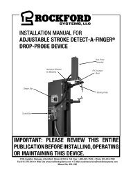
KSL-020 | Installation Manual for Detect-A-Finger Drop Probe Device for Riveters and Other Machines
Create successful ePaper yourself
Turn your PDF publications into a flip-book with our unique Google optimized e-Paper software.
INSTALLATION MANUAL FOR<br />
DETECT-A-FINGER DROP PROBE DEVICE<br />
FOR RIVETERS AND OTHER MACHINES<br />
Danger Sign<br />
Control Box<br />
Sensing <strong>Probe</strong> Clamp<br />
Sensing <strong>Probe</strong><br />
IMPORTANT: PLEASE REVIEW THIS ENTIRE<br />
PUBLICATION BEFORE INSTALLING, OPERATING<br />
OR MAINTAINING THIS DEVICE.<br />
5795 Logistics Parkway • Rock<strong>for</strong>d Systems, Illinois 61109 • Toll Free 1-800-922-7533 (USA only) • Phone (815) 874-7891<br />
Fax (815) 874-6144 • Web Site www.rock<strong>for</strong>dsystems.com • E-Mail customerservice@rock<strong>for</strong>dsystems.com<br />
<strong>Manual</strong> No. <strong>KSL</strong>-<strong>020</strong>
TABLE OF CONTENTS<br />
<strong>Detect</strong>-A-<strong>Finger</strong> <strong>Drop</strong> <strong>Probe</strong> <strong>Device</strong> - Riveter<br />
SECTION 1—IN GENERAL.........................................................2-7<br />
SECTION 4—REPLACEMENT PARTS.......................................... 19<br />
SECTION 2—INSTALLATION OF CONTROL..............................8-18<br />
Components in System / General.............................................8<br />
Preliminary Steps Be<strong>for</strong>e <strong>Installation</strong>.................................... 8-9<br />
Specifications <strong>and</strong> Operating Data...........................................9<br />
<strong>Installation</strong> of Components.............................................. 10-17<br />
<strong>Other</strong> <strong>Installation</strong> Considerations...................................... 17-18<br />
SECTION 3—OPERATION........................................................... 18<br />
SECTION 1—IN GENERAL<br />
Safety Precautions<br />
“ DANGER ”<br />
SECTION 5—TROUBLESHOOTING.............................................. 19<br />
SECTION 6—LONG-STROKE DEVICE.....................................20-24<br />
LAYOUT OF DETECT-A-FINGER SYSTEM.................................... 25<br />
SECTION 7—ORDER FORM........................................................ 26<br />
SECTION 8—RETURN AUTHORIZATION FORM........................... 27<br />
Danger is used to indicate the presence of a hazard which WILL cause SEVERE personal<br />
injury if the warning is ignored.<br />
THIS SAFETY ALERT SYMBOL IDENTIFIES IMPORTANT SAFETY MESSAGES IN THIS MANUAL. WHEN YOU<br />
SEE THIS SYMBOL , BE ALERT TO THE POSSIBILITY OF PERSONAL INJURY, AND CAREFULLY READ THE<br />
MESSAGE THAT FOLLOWS.<br />
Efficient <strong>and</strong> safe machine operation depends on the development, implementation <strong>and</strong> en<strong>for</strong>cement of a safety program. This program requires,<br />
among other things, the proper selection of point-of-operation guards <strong>and</strong> safety devices <strong>for</strong> each particular job or operation, a thorough safety<br />
training program <strong>for</strong> all machine personnel, that includes instruction on the proper operation of the machine, the point-of-operation guards <strong>and</strong><br />
safety devices on the machine, <strong>and</strong> a regularly scheduled inspection <strong>and</strong> maintenance program.<br />
Rules <strong>and</strong> procedures covering each aspect of your safety program should be developed <strong>and</strong> published both in an operator’s safety manual, as<br />
well as in prominent places throughout the plant <strong>and</strong> on each machine. Some rules or instructions which must be conveyed to your personnel <strong>and</strong><br />
incorporated into your program include:<br />
DANGER<br />
DANGER<br />
Never place your h<strong>and</strong>s or any part of your body in this machine.<br />
Never operate this machine without proper eye, face <strong>and</strong> body protection.<br />
Never operate this machine unless you are fully trained, instructed, <strong>and</strong> have read the instruction manual.<br />
Never operate this machine if it is not working properly—stop operating <strong>and</strong> advise your supervisor immediately.<br />
Never use a foot switch to operate this machine unless a point-of-operation guard or device is provided <strong>and</strong> properly<br />
maintained.<br />
Never operate this machine unless two-h<strong>and</strong> trip, two-h<strong>and</strong> control or presence sensing device is installed at the<br />
proper safety distance. Consult your supervisor should you have any questions regarding the proper safety distance.<br />
Never tamper with, rewire or bypass any control or component on this machine.<br />
A company’s safety program must involve everyone in the company, from top management to operators, since only as a group can any operational<br />
problems be identified <strong>and</strong> resolved. It is everyone’s responsibility to implement <strong>and</strong> communicate the in<strong>for</strong>mation <strong>and</strong> material contained in catalogs<br />
<strong>and</strong> instruction manuals to all persons involved in machine operation. If a language barrier or insufficient education would prevent a person from<br />
reading <strong>and</strong> underst<strong>and</strong>ing various literature available, it should be translated, read or interpreted to the person, with assurance that it is understood.<br />
For maintenance <strong>and</strong> inspection always refer to the OEM’s (Original Equipment Manufacturer’s) maintenance<br />
manual or owner’s manual. If you do not have an owner’s manual, please contact the original equipment<br />
manufacturer.<br />
© 2019 Rock<strong>for</strong>d Systems, LLC All rights reserved. Not to be reproduced in whole or in part without written permission. Litho in U.S.A.<br />
Rock<strong>for</strong>d Systems, LLC<br />
2 Call: 1-800-922-7533
Safety References<br />
OSHA’S ACT AND FEDERAL REGULATIONS<br />
Since the enclosed equipment can never overcome a mechanical<br />
deficiency, defect or malfunction in the machine itself, OSHA<br />
(Occupational Safety <strong>and</strong> Health Administration) has established certain<br />
safety regulations that the employers (users) must comply with so that<br />
the machines used in their plants, factories or facilities are thoroughly<br />
inspected <strong>and</strong> are in first-class operating condition be<strong>for</strong>e any of the<br />
enclosed equipment is installed.<br />
1. An Act – Public Law 91 - 596, 91st Congress, S. 2193,<br />
December 29, 1970<br />
Duties:<br />
Sec. 5. (a) Each employer —<br />
(1) shall furnish to each of his employees employment<br />
<strong>and</strong> a place of employment which are free from<br />
recognized hazards that are causing or are likely to cause<br />
death or serious physical harm to his employees;<br />
(2) shall comply with occupational safety <strong>and</strong> health st<strong>and</strong>ards<br />
promulgated under this Act.<br />
(b) Each employee shall comply with occupational safety <strong>and</strong><br />
health st<strong>and</strong>ards <strong>and</strong> all rules, regulations, <strong>and</strong> orders issued<br />
pursuant to this Act which are applicable to his own actions<br />
<strong>and</strong> conduct.<br />
2. OSHA’s Code of Federal Regulations, Subpart O, that an<br />
employer (user) must comply with include:<br />
Section 1910.211 Definitions<br />
Section 1910.212 (a) General Requirements <strong>for</strong> all <strong>Machines</strong><br />
Section 1910.217 Mechanical Power Presses<br />
Section 1910.219 (b)(1) Mechanical Power-Trans-mission<br />
Apparatus (Flywheel <strong>and</strong> Gear Covers)<br />
3. OSHA’s 29 Code of Federal Regulations, Subpart J 1910.147<br />
The Control of Hazardous Energy (Lockout / Tagout)<br />
4. OSHA’s Publications<br />
“General Industry Safety <strong>and</strong> Health Regulations Part 1910,” Code<br />
of Federal Regulations, Subpart O<br />
“Concepts <strong>and</strong> Techniques of Machine Safeguarding,” OSHA 3067,<br />
Revised 1992<br />
These publications can be obtained by contacting:<br />
US Department of Labor<br />
Occupational Safety <strong>and</strong> Health Administration<br />
Washington, DC 20210 (202) 219-5257<br />
SECTION 1—IN GENERAL<br />
<strong>Detect</strong>-A-<strong>Finger</strong> <strong>Drop</strong> <strong>Probe</strong> <strong>Device</strong> - Riveter<br />
ANSI SAFETY STANDARDS FOR MACHINES<br />
The most complete safety st<strong>and</strong>ards <strong>for</strong> machine tools are published<br />
in the ANSI (American National St<strong>and</strong>ards Institute) B11 series. The<br />
following is a list of each ANSI B11 St<strong>and</strong>ard available at the printing<br />
of this publication.<br />
B11.1 Mechanical Power Presses<br />
B11.2 Hydraulic Presses<br />
B11.3 Power Press Brakes<br />
B11.4 Shears<br />
B11.5 Iron Workers<br />
B11.6 Lathes<br />
B11.7 Cold Headers <strong>and</strong> Cold Formers<br />
B11.8 Drilling, Milling <strong>and</strong> Boring<br />
B11.9 Grinding <strong>Machines</strong><br />
B11.10 Sawing <strong>Machines</strong><br />
B11.11 Gear Cutting <strong>Machines</strong><br />
B11.12 Roll Forming <strong>and</strong> Roll Bending<br />
B11.13 Automatic Screw/Bar <strong>and</strong> Chucking<br />
B11.14 Coil Slitting <strong>Machines</strong><br />
B11.15 Pipe, Tube <strong>and</strong> Shape Bending<br />
B11.16 Metal Powder Compacting Presses<br />
B11.17 Horizontal Hydraulic Extrusion Presses<br />
B11.18 Coil Processing Systems<br />
B11.19 Per<strong>for</strong>mance Criteria <strong>for</strong> the Design, Construc-tion, Care<br />
<strong>and</strong> Operation of Safeguards as Referenced in the <strong>Other</strong><br />
B11 Machine Tool Safety St<strong>and</strong>ards<br />
B11.20 Safety Requirements <strong>for</strong> Manufacturing Sys-tems/Cells<br />
B11.21 Lasers<br />
B11.22 CNC Turning <strong>Machines</strong><br />
B11.23 Machining Centers<br />
B11/TR1 Ergonomic Considerations <strong>for</strong> the Design, <strong>Installation</strong><br />
<strong>and</strong> Use of Machine Tools<br />
B11/TR2 Mist Control<br />
B11/TR3 Hazard ID <strong>and</strong> Control<br />
B11/TR4 Control Reliability<br />
R15.06 Robotic Safeguarding<br />
These st<strong>and</strong>ards can be purchased by contacting:<br />
American National St<strong>and</strong>ards Institute, Inc.<br />
11 West 42nd Street<br />
New York, New York 10036<br />
(212) 642-4900<br />
OR<br />
Association of Manufacturing Technology (AMT)<br />
7901 Westpark Drive<br />
McLean, Virginia 22102-4269<br />
(703) 827-5211<br />
Rock<strong>for</strong>d Systems, LLC<br />
Call: 1-800-922-7533 3
SECTION 1—IN GENERAL<br />
<strong>Detect</strong>-A-<strong>Finger</strong> <strong>Drop</strong> <strong>Probe</strong> <strong>Device</strong> - Riveter<br />
NATIONAL SAFETY COUNCIL SAFETY MANUALS AND DATA<br />
SHEETS<br />
<strong>Other</strong> good references <strong>for</strong> safety on machine tools are the National<br />
Safety Council’s Safety <strong>Manual</strong>s <strong>and</strong> Data Sheets. These manuals <strong>and</strong><br />
data sheets are written by various committees including the Power<br />
Press, Forging <strong>and</strong> Fabricating Executive Committee. The following<br />
publications are available <strong>for</strong> all types of machines:<br />
MANUALS<br />
Power Press Safety <strong>Manual</strong> - 4th Edition<br />
Safeguarding Concept Illustrations - 6th Edition<br />
Forging Safety <strong>Manual</strong><br />
DATA SHEETS<br />
Bench <strong>and</strong> Pedestal Grinding Wheel Operations<br />
12304-0705<br />
Boring Mills, Horizontal Metal 12304-0269<br />
Boring Mills, Vertical 12304-0347<br />
Coated Abrasives 12304-0452<br />
Cold Shearing Billets <strong>and</strong> Bars in the Forging Industry<br />
12304-0739<br />
Degreasing (Liquid), Small Metal Parts 12304-0537<br />
Dies, Setup <strong>and</strong> Removal of Forging Hammer<br />
12304-0716<br />
Drill Presses, Metalworking 12304-0335<br />
Drills, Portable Reamer 12304-0497<br />
<strong>Drop</strong> Hammers, Steam 12304-0720<br />
Electrical Controls <strong>for</strong> Mechanical Power Presses<br />
12304-0624<br />
Forging Hammer Dies, Setup <strong>and</strong> Removal of<br />
12304-0716<br />
Forging Presses, Mechanical 12304-0728<br />
Gear-Hobbing <strong>Machines</strong> 12304-0362<br />
H<strong>and</strong>ling Materials in the Forging Industry 12304-0551<br />
Kick (Foot) Presses 12304-0363<br />
Lathes, Engine 12304-0264<br />
Milling <strong>Machines</strong>, Metalworking 12304-0364<br />
Planers, Metal 12304-0383<br />
Power Press (Mechanical) Point-of-Operation<br />
Safeguarding, Concepts of 12304-0710<br />
Power Press Point-of-Operation Safeguarding:<br />
Two-H<strong>and</strong> Control <strong>and</strong> Two-H<strong>and</strong> Tripping<br />
<strong>Device</strong>s 12304-0714<br />
Power Press Point-of-Operation Safeguarding: Type A<br />
<strong>and</strong> B Movable Barrier <strong>Device</strong>s 12304-0712<br />
Power Press Point-of-Operation Safeguarding:<br />
Point-of-Operation Guards 12304-0715<br />
Power Press Point-of-Operation Safeguarding:<br />
Presence Sensing <strong>Device</strong>s 12304-0711<br />
Power Press Point-of-Operation Safeguarding:<br />
Pullbacks <strong>and</strong> Restraint <strong>Device</strong>s 12304-0713<br />
Power Presses (Mechanical), Inspection <strong>and</strong><br />
Maintenance of 12304-0603<br />
Power Presses (Mechanical), Removing Pieceparts<br />
from Dies in 12304-0534<br />
Power Press, Setting Up <strong>and</strong> Removing Dies<br />
12304-0211<br />
Press Brakes 12304-0419<br />
Robots 12304-0717<br />
Saws, Metal (Cold Working) 12304-0584<br />
Shapers, Metal 12304-0216<br />
Shears, Alligator 12304-0213<br />
Shears, Squaring, Metal 12304-0328<br />
Upsetters, 12304-0721<br />
These manuals <strong>and</strong> data sheets can be purchased by contacting:<br />
National Safety Council<br />
1121 Spring Lake Drive<br />
Itasca, IL 60143-3201<br />
(708) 295-1121<br />
For additional safety in<strong>for</strong>mation <strong>and</strong> assistance in devising,<br />
implementing or revising your safety program, please contact the<br />
machine manufacturer, your state <strong>and</strong> local safety councils, insurance<br />
carriers, national trade associations <strong>and</strong> your state’s occupational<br />
safety <strong>and</strong> health administration.<br />
Warranty, Disclaimer <strong>and</strong> Limitation of Liability<br />
WARRANTY<br />
Rock<strong>for</strong>d Systems, LLC warrants that this product will be free from defects in material <strong>and</strong> workmanship <strong>for</strong> a period of 12 months from the date of shipment<br />
thereof. ROCKFORD SYSTEMS LLC’S OBLIGATION UNDER THIS WARRANTY IS EXPRESSLY AND EXCLUSIVELY LIMITED to repairing or replacing such products<br />
which are returned to it within the warranty period with shipping charges prepaid <strong>and</strong> which will be disclosed as defective upon examination by Rock<strong>for</strong>d<br />
Systems, LLC This warranty will not apply to any product which will have been subject to misuse, negligence, accident, restriction <strong>and</strong> use not in accordance<br />
with Rock<strong>for</strong>d Systems, LLC’s instructions or which will have been altered or repaired by persons other than the authorized agent or employees of Rock<strong>for</strong>d<br />
Systems, LLC Rock<strong>for</strong>d Systems, LLC’s warranties as to any component part is expressly limited to that of the manufacturer of the component part.<br />
DISCLAIMER<br />
The <strong>for</strong>egoing Warranty is made in lieu of all other warranties, expressed or<br />
implied, <strong>and</strong> of all other liabilities <strong>and</strong> obligations on the part of Rock<strong>for</strong>d<br />
Systems, LLC, including any liability <strong>for</strong> negligence, strict liability, or<br />
otherwise, <strong>and</strong> any implied warranty of merchantability or fitness <strong>for</strong> a<br />
particular purpose is expressly disclaimed.<br />
LIMITATION OF LIABILITY<br />
Under no circumstances, including any claim of negligence, strict liability, or otherwise,<br />
shall Rock<strong>for</strong>d Systems, LLC be liable <strong>for</strong> any incidental or consequential damages, or<br />
any loss or damage resulting from a defect in the product of Rock<strong>for</strong>d Systems, LLC<br />
Rock<strong>for</strong>d Systems, LLC<br />
4 Call: 1-800-922-7533
Operator Safety Precaution Pamphlet (Attachment <strong>for</strong> machine operators)<br />
SECTION 1—IN GENERAL<br />
<strong>Detect</strong>-A-<strong>Finger</strong> <strong>Drop</strong> <strong>Probe</strong> <strong>Device</strong> - Riveter<br />
Accompanying this equipment is an 8-1/2”<br />
x 11” operator safety precaution pamphlet,<br />
Part No. KSC-000, <strong>for</strong> anyone operating<br />
the machine where this equipment will be<br />
installed. This precaution pamphlet is to be<br />
given to all operators, including setup people,<br />
maintenance personnel <strong>and</strong> supervisors.<br />
This pamphlet should also be attached to<br />
the machine, readily accessible <strong>and</strong> visible<br />
to the operator. (A hole in the corner of this<br />
precaution pamphlet is provided <strong>for</strong> attaching<br />
purposes.) Additional copies of this precaution<br />
are available. Please call, e-mail, write, fax, or<br />
use the order <strong>for</strong>m found on a later page in<br />
this manual.<br />
1<br />
2<br />
3<br />
4<br />
5<br />
6<br />
7<br />
Do Not Operate This Machine<br />
Until You Read <strong>and</strong> Underst<strong>and</strong> the<br />
Following Safety Precautions.<br />
Never operate this machine until you underst<strong>and</strong> that this<br />
machine is dangerous <strong>and</strong> if you place your h<strong>and</strong>s, or any<br />
part of your body in this machine it could result in the loss of<br />
fingers, limbs or even death.<br />
Never operate this machine without the use of a guard or<br />
safety device that will always protect you from bodily injury.<br />
Never use a foot switch to operate this machine unless<br />
a point-of-operation guard or device is provided <strong>and</strong><br />
properly maintained.<br />
Never “ride” the foot pedal or foot switch. Never rest your<br />
foot on top of the foot pedal or inside the foot switch. Always<br />
remove your foot completely from the foot pedal or foot<br />
switch after each cycle <strong>and</strong> any time you are not intending<br />
to trip the machine.<br />
Always use h<strong>and</strong> tools <strong>for</strong> feeding or retrieving material<br />
from the point of operation or any other hazardous part of the<br />
machine. Never reach through or into die area <strong>for</strong> any reason.<br />
Never operate this machine unless you feel you have been<br />
fully trained <strong>and</strong> have received <strong>and</strong> underst<strong>and</strong> all operating<br />
instructions. Make sure you know how the machine works<br />
<strong>and</strong> how it is controlled.<br />
Never operate this machine until you test the machine with its<br />
guard or safety device be<strong>for</strong>e you start or restart production.<br />
Do not begin operating the machine unless you are sure the<br />
safeguarding is adjusted properly <strong>and</strong> working correctly. If you<br />
are not sure call your supervisor.<br />
Never operate this machine if it is not working properly or if<br />
you notice any unusual noise or change in the per<strong>for</strong>mance<br />
of the machine. Stop operating the machine immediately <strong>and</strong><br />
advise your supervisor.<br />
Front<br />
9<br />
10<br />
11<br />
12<br />
13<br />
14<br />
15<br />
Never operate this machine with pullbacks unless they are<br />
adjusted properly <strong>for</strong> you. Have your supervisor show you<br />
manually that when the ram descends the pullbacks will<br />
pull your fingers clear of any pinch points. Always wear your<br />
wristlets properly <strong>and</strong> securely.<br />
Never operate this machine with pullbacks without reading<br />
<strong>and</strong> underst<strong>and</strong>ing the instructions. Instructions must be kept<br />
with the pullback device at all times <strong>and</strong> made available to<br />
you. Obtain, read <strong>and</strong> follow these instructions.<br />
Never operate this machine unless two-h<strong>and</strong> trip, two-h<strong>and</strong><br />
control or presence sensing device are installed correctly <strong>and</strong><br />
at the proper safety distance. Consult your supervisor should<br />
you have any questions regarding the proper safety distance.<br />
Never tamper with, rewire or bypass any control, component<br />
or safeguard on this machine.<br />
Always wear safety glasses, ear protection <strong>and</strong> any other<br />
personal protection equipment needed when operating this<br />
machine.<br />
Be sure all persons are clear of the machine be<strong>for</strong>e it is<br />
cycled, especially when multiple operators are present. Do<br />
not operate machine unless you <strong>and</strong> every operator <strong>and</strong>/or<br />
helper are protected from injury by a guard or safety device.<br />
Always stay alert (don’t daydream) <strong>and</strong> never operate this<br />
machine while under the influence of alcohol or any other drug<br />
including prescription medications.<br />
Maintenance <strong>and</strong> Die Set-Up Personnel: Never work on<br />
this machine unless power is off, flywheel is at rest, safety<br />
blocks are used between dies, ram <strong>and</strong> bolster plate <strong>and</strong><br />
all energy (electrical, air, hydraulic, etc.) are in a zero state.<br />
When a language barrier or insufficient<br />
education prevents a person from reading or<br />
underst<strong>and</strong>ing the contents of this operator<br />
safety precaution pamphlet, you should either<br />
translate this in<strong>for</strong>mation or have it read or<br />
interpreted to the person. Make sure that the<br />
person underst<strong>and</strong>s the in<strong>for</strong>mation. To order<br />
this pamphlet in Spanish, use Part No. KSC-<br />
000S; in French, use Part No. KSC-000F.<br />
This precaution pamphlet must be reviewed daily.<br />
8<br />
16<br />
NOTICE TO EMPLOYER: A copy of this “Operator Safety Precautions” must be given to all operators (including die setup<br />
people, maintenance personnel <strong>and</strong> supervisors) of this machine. A copy should also be hung on the machine<br />
readily accessible <strong>and</strong> visible to the operator. Additional copies of this precaution are available upon request.<br />
Just call or write.<br />
IMPORTANT: Where a language barrier or insufficient schooling would prevent a person from reading <strong>and</strong> underst<strong>and</strong>ing<br />
the contents of this Operator Safety Precaution, you should either translate this in<strong>for</strong>mation or have it read or<br />
interpreted to the person, with assurance that it is understood.<br />
THIS PRECAUTION MUST BE REVIEWED DAILY.<br />
Back<br />
(Continued on next page.)<br />
Rock<strong>for</strong>d Systems, LLC<br />
Call: 1-800-922-7533 5
SECTION 1—IN GENERAL<br />
<strong>Detect</strong>-A-<strong>Finger</strong> <strong>Drop</strong> <strong>Probe</strong> <strong>Device</strong> - Riveter<br />
Danger Sign(s) to be Mounted on Machine<br />
Accompanying this equipment are two 5” x 6” polyethylene danger signs, Part Nos. KSC-054 <strong>and</strong><br />
KSC-055. These signs MUST BE PERMANENTLY MOUNTED IN A PROMINENT LOCATION on the machine<br />
where this equipment is installed. Both signs must be in a LOCATION THAT IS EASILY VISIBLE to the<br />
operator, setup person, or other personnel who work on or around this machine. ALWAYS mount<br />
these signs with bolts or rivets when installing the enclosed equipment.<br />
If any danger sign becomes destroyed or unreadable, the sign must be replaced immediately. Contact factory <strong>for</strong> replacement danger sign(s).<br />
Never operate this machine unless the danger sign(s) is in place.<br />
Front Side<br />
Reverse Side<br />
Part No. KSC-055 Danger Sign<br />
(Foot) - St<strong>and</strong>ard<br />
Part No. KSC-055S - Spanish<br />
Part No. KSC-055F - French<br />
“Mechanical Power Press Safety” Booklet<br />
A copy of Booklet No. MPPS (“Mechanical Power Press Safety”) is available upon request. This booklet is copied verbatim from the CFR (Code<br />
of Federal Regulations) <strong>and</strong> contains all relevant sections of the OSHA Regulations concerning power presses with which an employer (user)<br />
must comply. The enclosed equipment must be installed, used <strong>and</strong> maintained to meet these regulations. Specifically, any time a foot switch is<br />
used, a suitable point-of-operation safeguard or device must be used to prevent bodily injury. In addition, every press must be provided with a<br />
point-of-operation safeguard! Please review this booklet be<strong>for</strong>e installing the enclosed equipment. If you are unfamiliar with these detailed safety<br />
regulations, which include regulations on safeguarding the point of operation properly, you may want to attend our regularly scheduled machine<br />
safeguarding seminars. To obtain detailed in<strong>for</strong>mation about these training seminars, please call, e-mail, fax, or write. Our telephone <strong>and</strong> fax<br />
numbers, <strong>and</strong> addresses are on the front cover of this manual.<br />
(Continued on next page.)<br />
Rock<strong>for</strong>d Systems, LLC<br />
6 Call: 1-800-922-7533
Danger <strong>and</strong> Warning Labels Provided on Control Box<br />
The illustrated danger <strong>and</strong> warning labels are<br />
affixed to all control boxes provided. All personnel<br />
operating or working around the machine, where<br />
this control box is installed, must be required to<br />
read, underst<strong>and</strong> <strong>and</strong> adhere to all dangers <strong>and</strong><br />
warnings. If any of these labels become destroyed<br />
or unreadable, labels MUST be replaced. Contact<br />
factory immediately <strong>for</strong> replacement labels <strong>and</strong><br />
do not operate machine until danger <strong>and</strong> warning<br />
labels are all in place.<br />
SECTION 1—IN GENERAL<br />
<strong>Detect</strong>-A-<strong>Finger</strong> <strong>Drop</strong> <strong>Probe</strong> <strong>Device</strong> - Riveter<br />
Label No. KST-154<br />
FOR REPLACEMENT SIGNS CALL, E-MAIL, OR FAX FACTORY<br />
OR USE ORDER FORM TOWARDS THE BACK OF THIS MANUAL.<br />
Rock<strong>for</strong>d Systems, LLC.<br />
5795 Logistics Parkway<br />
Rock<strong>for</strong>d, Illinois 61109<br />
Toll Free: 1-800-922-7533 (USA only)<br />
Phone: (815) 874-7891<br />
Fax: (815) 874-6144<br />
Web Site: www.rock<strong>for</strong>dsystems.com<br />
E-Mail: customerservice@rock<strong>for</strong>dsystems.com<br />
(Continued on next page.)<br />
Rock<strong>for</strong>d Systems, LLC<br />
Call: 1-800-922-7533 7
SECTION 2—INSTALLATION<br />
<strong>Detect</strong>-A-<strong>Finger</strong> <strong>Drop</strong> <strong>Probe</strong> <strong>Device</strong> - Riveter<br />
Components in the System<br />
Individual packages may vary in contents. However, a packing list is always enclosed showing exactly what material was shipped on this order.<br />
Please check the components actually received against this packing list. St<strong>and</strong>ard components of this system are as follows:<br />
q Literature Folder<br />
q Control Box (Right or Left Mount)<br />
q Sensing <strong>Probe</strong> (2) (<strong>for</strong>med by user) <strong>and</strong> Sensing <strong>Probe</strong> Clamp<br />
(Sensing probe on the long-stroke devices (see pages 20-23) is <strong>for</strong>med as illustrated.)<br />
<strong>Other</strong> components that may be required <strong>for</strong> a particular application are:<br />
q Disconnect Switch<br />
q Motor Starter<br />
q Trans<strong>for</strong>mer<br />
q Air Cylinder Assembly<br />
q Solenoid Air Valve or Electric Solenoid (Pull Type)<br />
q Air Filter-Regulator-Gauge <strong>and</strong> Lubricator Assembly<br />
q Lockout Valve<br />
q Foot Switch<br />
General In<strong>for</strong>mation<br />
The purpose of the <strong>Detect</strong>-A-<strong>Finger</strong> <strong>Drop</strong> <strong>Probe</strong> <strong>Device</strong> is to effectively reduce accidents on applications where the operator’s fingers may enter<br />
the point of operation. The components of this system are (1) a “Mechanical Sensing <strong>Probe</strong>” shaped to fit over or around the workpiece <strong>and</strong> (2) a<br />
Control Box. When the operator initiates a machine cycle, the “Sensing <strong>Probe</strong>” is released <strong>and</strong> drops by gravity over or around the workpiece. If<br />
the operator’s fingers are still in the danger area, the “Sensing <strong>Probe</strong>” cannot reach its preset down position <strong>and</strong> the machine is prevented from<br />
cycling. Conversely, if no obstruction prevents the “Sensing <strong>Probe</strong>” from dropping, then as soon as it reaches its preset down position, the control<br />
unit will allow the machine to cycle.<br />
The control box is ruggedly built to provide continued successful operation under operating conditions usually found around this type of machinery.<br />
The sensing probe that operates the limit switch is tied into the control relay (in the control box) <strong>and</strong> when properly wired into the machine system<br />
prevents cycling of the machine accidentally or intentionally. This can be confirmed by moving the “Sensing <strong>Probe</strong>” manually without operating the<br />
h<strong>and</strong> or foot actuating means.<br />
Preliminary Steps Be<strong>for</strong>e <strong>Installation</strong><br />
Be<strong>for</strong>e proceeding with the installation of the enclosed equipment, the following preliminary steps should be considered:<br />
1. Read <strong>and</strong> make sure you underst<strong>and</strong> this entire <strong>Installation</strong> <strong>Manual</strong>.<br />
2. Ensure that the machine is in first-class condition. Be<strong>for</strong>e starting any installation it is essential that the machine be thoroughly inspected.<br />
Make sure all mechanical components <strong>and</strong> collateral equipment are in first-class operating condition. Your inspection should be in accordance<br />
with the machine manufacturer’s installation <strong>and</strong> maintenance instruction manual. If you have any doubts or questions concerning the condition<br />
of the machine, contact the machine manufacturer <strong>for</strong> assistance. Repair or replace all parts not operating properly be<strong>for</strong>e proceeding.<br />
Inspection <strong>and</strong> maintenance programs must be established <strong>and</strong> implemented to keep machines in<br />
first-class condition. Programs must include thorough inspections of each machine on a weekly<br />
basis <strong>and</strong> records kept of these inspections. Any part of the machine that is worn, damaged or is not<br />
operating properly must immediately be replaced or repaired be<strong>for</strong>e the machine is used.<br />
3. Verify that the machine is in first-class condition <strong>and</strong> operating properly. Shut off all power to the machine. Padlock the disconnecting means<br />
in the “off” position <strong>and</strong> do not actuate the machine again until the installation of all package components has been completed. Lockout/tagout<br />
energy isolation procedures must also be practiced <strong>and</strong> en<strong>for</strong>ced <strong>for</strong> all energy sources when installing the enclosed equipment, setting up <strong>and</strong><br />
maintaining the machine.<br />
(Continued on next page.)<br />
Rock<strong>for</strong>d Systems, LLC<br />
8 Call: 1-800-922-7533
Preliminary Steps Be<strong>for</strong>e <strong>Installation</strong> (continued)<br />
SECTION 2—INSTALLATION<br />
<strong>Detect</strong>-A-<strong>Finger</strong> <strong>Drop</strong> <strong>Probe</strong> <strong>Device</strong> - Riveter<br />
The operator must be protected from all hazards. All applicable sections of OSHA Section 1910.212, General Machine<br />
Safeguarding, <strong>and</strong> ANSI B154.1 <strong>for</strong> Rivet Setting Equipment, must be complied with on all machines where this equipment<br />
is installed.<br />
The <strong>Detect</strong>-A-<strong>Finger</strong> controls are applicable on most types of riveting, eyeletting, staking <strong>and</strong> similarly operated assembly<br />
<strong>and</strong> fastening machines. The function of the <strong>Detect</strong>-A-<strong>Finger</strong> device, when properly installed, adjusted <strong>and</strong> maintained,<br />
is to keep the operator from inadvertently cycling the machine with fingers in the point of operation. The <strong>Detect</strong>-A-<strong>Finger</strong><br />
control does not incorporate single stroke capability. This control only provides an interface between the clutch actuator<br />
<strong>and</strong> the trip control operating means which will not allow stroke initiation unless the area being probed is cleared of all<br />
unwanted obstructions. To accomplish this protection, the <strong>Detect</strong>-A-<strong>Finger</strong> must be properly installed on the machine <strong>and</strong><br />
the device must be properly maintained <strong>and</strong> adjusted by the user. A properly designed sensing probe must be used <strong>and</strong><br />
additional sensing probe safeguarding must be provided where applicable. This device does not protect the operator if<br />
fingers are placed above the sensing probe. This device cannot prevent clutch or machine malfunction or repeat strokes<br />
of the machine.<br />
Be<strong>for</strong>e starting any installation work, it is imperative that the machine’s clutch is inspected <strong>and</strong> exhibits proper operation.<br />
Run the machine in a normal operating sequence to determine proper operation. Do not install the <strong>Detect</strong>-A-<strong>Finger</strong> on<br />
a machine that does not function properly. When the machine is operating satisfactorily, shut off the power with the<br />
disconnect switch <strong>and</strong> do not operate the machine again until installation is complete. Use of a lockout device <strong>and</strong> padlock<br />
on the disconnect h<strong>and</strong>le must be used during this period.<br />
The maintenance <strong>and</strong> inspection section in this manual cannot be all-inclusive <strong>for</strong> maintaining machines. Always refer<br />
to the original machine manufacturer’s maintenance manuals or owner’s manual. If you do not have an owner’s manual,<br />
please contact the original equipment manufacturer.<br />
Specifications <strong>and</strong> Operating Data<br />
CONTROL BOX<br />
Part Number...................................................RKC-000 or RKC-001<br />
Fuse............................................................................... 313 Series,<br />
3AG, 3 Amps,...................................................................................<br />
.............................................................................. 250V, Slow Blow<br />
Input Voltage........................................ 115 + 15% VAC, 50/60 Hz<br />
Operating Current................................................ 0.8 Amps Typical<br />
Output Relay Ratings Resistive General Use<br />
10A 110VAC 7.5A 110VAC<br />
7.5A 220VAC 5A 220VAC<br />
10A 30VDC<br />
Operating Current................................................ 3.0 Amps Typical<br />
Duty Cycle..............................................25% (10 Second Maximum<br />
........................................................................Continuous On-Time)<br />
Stroke..........................Travel Adjustable to 1.75 (1-3/4) Inches Max.<br />
Mechanical Life.................................. Relay - 10 Million Operations<br />
........................................... Rotary Solenoid - 100 Million Operations<br />
Weight................................................................................3.5 Lbs.<br />
SENSING PROBE (UNFORMED)<br />
Part Number...................................................................... FCT-030<br />
Wire Size.................................................156 Dia. x 18 inches Long<br />
Materia..................................................... Aluminum Rod (St<strong>and</strong>ard)<br />
Total Weight......................................... (Including <strong>Probe</strong> <strong>and</strong> Clamp)<br />
............................................................. 0.5 lbs. Maximum Allowable<br />
Right Side Mount Control Box (Part<br />
No. RKC-000)<br />
Left Side Mount<br />
Control Box<br />
(Part No. RKC-001)<br />
Rock<strong>for</strong>d Systems, LLC<br />
Call: 1-800-922-7533 9
SECTION 2—INSTALLATION<br />
<strong>Detect</strong>-A-<strong>Finger</strong> <strong>Drop</strong> <strong>Probe</strong> <strong>Device</strong> - Riveter<br />
<strong>Installation</strong> of Control Package Components<br />
INSTALLATION MANUAL<br />
Included with every shipment is an installation manual, “Operator Safety Precaution” Pamphlet (Part No. KSC-000), danger sign(s), <strong>and</strong><br />
electrical schematics. These publications must be available <strong>and</strong> fully understood be<strong>for</strong>e any retrofit installation begins. Please notify Rock<strong>for</strong>d<br />
Systems, LLC immediately if there are any questions about the components received.<br />
FOOT SWITCH DANGER SIGN - PART NO. KSC-055<br />
If a foot switch is ordered, a 5” x 6” polyethylene danger sign, as illustrated on page 6, is supplied. It is<br />
imperative that this sign be firmly attached to the machine in a location readily visible to all personnel.<br />
Suggested mounting instructions are shown on the reverse side of this sign.<br />
Sign No. KSC-055<br />
This sign must be the first thing mounted to prevent any possibility that it might be overlooked. If<br />
this sign becomes destroyed or unreadable, it must be replaced immediately. Contact factory <strong>for</strong><br />
replacement <strong>and</strong> do not operate the machine until the danger sign is in place.<br />
CONTROL BOX (RKC-000 OR RKC-001) For part Nos. RKC-700 through RKC-701, please see pages 20 - 23.<br />
Two models are available to fit the <strong>Detect</strong>-A-<strong>Finger</strong> to various machines. Part No. RKC-000 mounts on the right side of a machine.<br />
Part No. RKC-001 mounts on the left side of a machine. The drop rod exits bottom left of Part No. RKC-000. The drop rod exits bottom right of<br />
Part No. RKC-001. The selected model should provide access to the machine <strong>for</strong> general maintenance <strong>and</strong> adjustments. It should be installed<br />
so that the sensing probe can be positioned above the point of operation without obstructing the work area. The sensing probe design should<br />
be as short <strong>and</strong> rigid as possible.<br />
Photo 2.1 - Part No. RKC-000 (Right Side Mount)<br />
Fuse Holder<br />
<strong>and</strong> Fuse<br />
“Power On”<br />
Indicator Light<br />
Bridge Rectifier<br />
Rotary Solenoid<br />
Return Spring<br />
Door<br />
Lock<br />
<strong>Drop</strong> Rod<br />
Limit Switch<br />
Relay<br />
(Continued on next page.)<br />
Rock<strong>for</strong>d Systems, LLC<br />
10 Call: 1-800-922-7533
SECTION 2—INSTALLATION<br />
<strong>Detect</strong>-A-<strong>Finger</strong> <strong>Drop</strong> <strong>Probe</strong> <strong>Device</strong> - Riveter<br />
CONTROL BOX (continued)<br />
The control box includes a “power on” indicator light, a through-the-door fuse holder <strong>for</strong> ease of fuse inspection <strong>and</strong> replacement, a relay, terminal<br />
strips, <strong>and</strong> a PC board assembly. The door of the control box can be locked to prevent unauthorized personnel from opening the control box.<br />
ALWAYS BE SURE TO DISCONNECT POWER BEFORE OPENING THE CONTROL BOX DOOR.<br />
Sensing <strong>Probe</strong><br />
The drop rod is allowed to drop by gravity when the rotary solenoid is energized. The action-arm return sprin returns this assembly when the power<br />
is removed. The DC voltage <strong>for</strong> the rotary solenoid is obtained from a full-wave bridge rectifier. The drop rod is guided in nylon bearings <strong>for</strong> long life<br />
<strong>and</strong> smooth operation. The limit switch actuates the control relay in the control box at the end of the drop rod stroke. The stroke is easily adjusted<br />
by repositioning the limit switch actuating collar. A set screw is provided to lock the collar in position.<br />
Two 18-inch pieces of 5/32 (.156) inch diameter aluminum rod are furnished with each <strong>Detect</strong>-A-<strong>Finger</strong>. <strong>Other</strong> materials or custom made<br />
configurations may also be used. The only restriction is the total weight of the probe assembly (including the clamp). The action-arm return spring<br />
is capable of returning 0.5 pounds maximum. The user must determine <strong>and</strong> <strong>for</strong>m the best shape to accommodate the particular part being run.<br />
This device must be designed, constructed <strong>and</strong> arranged to create a protected area, <strong>and</strong> to prevent engagement of the machine. In pneumatic- <strong>and</strong><br />
hydraulic-powered machines, this device must prevent energizing of the control valve when an operator’s finger or other part of the body is within<br />
the hazardous area. See Photo 2.2.<br />
Figure 2.1 - Examples of <strong>Drop</strong> <strong>Probe</strong> Rod shapes:<br />
Mounting<br />
Locate the <strong>Detect</strong>-A-<strong>Finger</strong> control box on the machine in the best<br />
location <strong>for</strong> general maintenance, adjustment, <strong>and</strong> tool changing. The<br />
bottom of the drop rod, in its full down position, should barely clear the<br />
workpiece. This location allows <strong>for</strong> final positioning. If special mounting<br />
brackets are fabricated, they must be able to support the sensing probe<br />
<strong>and</strong> withst<strong>and</strong> any shock <strong>and</strong> vibration that may be encountered during<br />
machine operation. Be sure to insulate any <strong>and</strong> all special brackets.<br />
Photos at right show typical installations.<br />
Photo 2.2<br />
The control box should also be mounted as far <strong>for</strong>ward as possible on<br />
the machine to provide <strong>for</strong> the minimum angle of the sensing probe.<br />
This position will contribute to a long mechanical life of the device since<br />
it minimizes the side loading on the drop rod bearings. See Photo 2.4.<br />
Photo 2.3 Photo 2.4<br />
Rock<strong>for</strong>d Systems, LLC<br />
Call: 1-800-922-7533 11
SECTION 2—INSTALLATION<br />
<strong>Detect</strong>-A-<strong>Finger</strong> <strong>Drop</strong> <strong>Probe</strong> <strong>Device</strong> - Riveter<br />
<strong>Other</strong> Required Components (Not part of package unless specifically ordered)<br />
MAIN POWER DISCONNECT SWITCH<br />
A main power disconnect switch may have been supplied in the package shipment. This switch is designed to disconnect the primary voltage to<br />
the machine <strong>and</strong> lock it out. Please refer to the enclosed wiring schematics <strong>for</strong> proper wiring of this switch.<br />
OSHA Regulation 1910.217 (b)(8), ANSI St<strong>and</strong>ards B11.1 <strong>and</strong> B11.3 require that:<br />
“A main power disconnect switch capable of being locked only in the Off position shall be provided with every power press control system.” If the<br />
machine already has a main power disconnect switch, it must be checked <strong>for</strong> the “locking off” <strong>and</strong> lockout feature. Some switches use construction<br />
which can be easily altered mechanically to comply with this requirement. If this is not possible, or an electrical disconnect switch is not provided,<br />
then you must obtain <strong>and</strong> install a proper disconnect switch. (To purchase a disconnect switch, please contact Rock<strong>for</strong>d Systems, LLC)<br />
MOTOR STARTER<br />
A nonreversing motor starter may have been supplied in this shipment. The main purpose of this starter is to drop out the main drive motor <strong>and</strong><br />
power to the controls when a power failure occurs. The <strong>Detect</strong>-A-<strong>Finger</strong> control must be tied into a motor starter. (For safety reasons do not run a<br />
separate line to the control. Please refer to the enclosed wiring schematics <strong>for</strong> proper wiring of this starter.)<br />
OSHA Regulation 1910.217 (b)(8) <strong>and</strong> ANSI St<strong>and</strong>ards B11.1 require that:<br />
“The motor start button shall be protected against accidental operation.”<br />
“All mechanical power press controls shall incorporate a type of drive motor starter that will disconnect the drive motor from the power source in<br />
event of control voltage or power source failure, <strong>and</strong> require operation of the motor start button to restart the motor when voltage conditions are<br />
restored to normal.”<br />
These requirements are normally met by using a magnetic motor starter. This starter (if furnished) operates with a 120 VAC coil. Refer to the<br />
electrical schematics supplied <strong>for</strong> details on wiring the starter <strong>and</strong> associated motor start/stop push buttons.<br />
TRANSFORMER PART NO. RSF-021<br />
This externally mounted trans<strong>for</strong>mer may have been supplied in this shipment. It has a 100VA, 230/460 volt primary <strong>and</strong> a 115 volt fused<br />
secondary. The fuse is 1 amp, 250 volt <strong>and</strong> is accessible from the outside of the trans<strong>for</strong>mer housing.<br />
Components Required <strong>for</strong> Typical Applications<br />
Inspect each machine where these <strong>Detect</strong>-A-<strong>Finger</strong>s will be installed. Most machines are controlled electrically, pneumatically or mechanically;<br />
however, other components may be required. Review this section <strong>for</strong> typical applications of the <strong>Detect</strong>-A-<strong>Finger</strong>. Accessory equipment <strong>and</strong><br />
components such as solenoid air valves, air cylinders, or electric solenoids are available from Rock<strong>for</strong>d <strong>for</strong> your convenience. If you require<br />
application assistance <strong>for</strong> these components, please contact the factory.<br />
All mechanically operated machines that are powered with flywheels, must incorporate single-stroke capability. Please consult factory <strong>for</strong> single<br />
stroke (single cycle) conversion packages when required.<br />
If single-stroke capability is dependent upon spring action then this feature must be inspected. This spring must be of the compression type,<br />
operating on a rod, or guided in a hole or tube, <strong>and</strong> designed to prevent interleaving of the spring coils in the event of breakage.<br />
Mechanical to Electro-Pneumatic Conversion<br />
Convert from mechanical operation by removing the h<strong>and</strong> or foot treadle <strong>and</strong> replacing it with an air cylinder. The cylinder bore <strong>and</strong> stroke (push or<br />
pull type) can be determined from actual machine measurements <strong>and</strong> the location of attachment to the linkage. The air cylinder is controlled by a<br />
three-way, normally closed, 120 VAC solenoid air valve. A filter-regulator-lubricator <strong>and</strong> pressure gauge assembly is also required. In most cases,<br />
the <strong>Detect</strong>-A-<strong>Finger</strong> controls the solenoid air valve.<br />
(Continued on next page.)<br />
Rock<strong>for</strong>d Systems, LLC<br />
12 Call: 1-800-922-7533
SECTION 2—INSTALLATION<br />
<strong>Detect</strong>-A-<strong>Finger</strong> <strong>Drop</strong> <strong>Probe</strong> <strong>Device</strong> - Riveter<br />
Mechanical to Electro-Pneumatic Conversion (continued)<br />
RCL SERIES AIR CYLINDERS (See Specification Sheet No. <strong>KSL</strong>-092)<br />
Photo 2.5<br />
One of the following pull-type air cylinders may be adequate to<br />
operate the machine:<br />
Part<br />
Number<br />
Bore<br />
(Inches)<br />
Stroke<br />
(Inches)<br />
Lbs. Pull<br />
(@ 75 PSI)<br />
Overall<br />
Length “A”<br />
Pull<br />
RCL-001<br />
RCL-002<br />
1.125<br />
1.500<br />
1.0<br />
1.0<br />
50<br />
100<br />
10.25”<br />
15.75”<br />
“A”<br />
RCL-003<br />
2.000<br />
2.0<br />
200<br />
19.75”<br />
Single-acting spring-return air cylinders are usually supplied with a swivel-clevis mount as st<strong>and</strong>ard. <strong>Other</strong> special cylinders, such as clevis mount,<br />
flange mount (either end) or foot mount are also available. They can be push type (spring inside cylinder), or pull type (spring on cylinder rod, as<br />
illustrated). The main consideration must be that the cylinder is a single-acting spring-return type (not double acting) to meet best safety practices.<br />
When mounting the cylinder, be sure it is secured in such a manner that it will not vibrate loose, bind or rub on some other part of the machine.<br />
The assembly consists of the cylinder, two mounting feet, mounting pin, drive yoke, drive pin, <strong>and</strong> yoke lock nut. This assembly is illustrated in<br />
Figure 2.3 on the next page. Locate this assembly on the machine so that the feet can be mounted to a convenient surface. The yoke should be<br />
attached to the machine linkage, <strong>and</strong> the air inlet should be oriented toward the air solenoid valve location.<br />
The air cylinder should be mounted in the most logical position to operate the machine linkage most efficiently. The main requirement in locating<br />
the cylinder assembly, is that the piston rod will have a straight, in-line pull (or push) when attached to the operating linkage. When<br />
applying an air cylinder to the machine, make sure that the cylinder rod, yoke or any moving parts will not bind after installation.<br />
Adjust so that the air cylinder bottoms at the end of each stroke. The air cylinder will operate in any position. The operating linkage may be connected<br />
to the air cylinder by any convenient means. Be sure the rod stroke is not too long because it could cause jackknifing of the cylinder. If this is<br />
a concern, shorter stroke cylinders are available. Too much air pressure may damage the operating linkage. Please consider these points when<br />
installing any air cylinder.<br />
Make certain that the drive yoke <strong>and</strong> lock nut are located approximately halfway down on the threaded portion of the piston rod in order to provide<br />
<strong>for</strong> either up or down adjustment when necessary. Attach one end of the flexible rubber hose in the threaded cylinder inlet port <strong>and</strong> tighten firmly.<br />
Note: Threaded air joints do not generally require sealant; however, “Teflon” tape may be used to prevent leakage.<br />
Photo 2.6<br />
SOLENOID AIR VALVE ASSEMBLY (See enclosed <strong>Installation</strong> Sheet No. <strong>KSL</strong>-151.)<br />
PART NO. RCD-006<br />
If furnished, the Solenoid Air Valve is a three-way, normally closed, quick- exhaust type. This<br />
assembly consists of the electric air solenoid valve, exhaust air muffler, steel mounting bracket<br />
<strong>and</strong> flexible hose.<br />
Mount the air muffler on the threaded exhaust port located on top of the valve. Assemble the<br />
mounting bracket to the base of the valve <strong>and</strong> orient this assembly so that the air outlet port<br />
(marked “1” on the valve body) points toward the air cylinder <strong>and</strong> is within reach of the flexible<br />
hose. Next attach this hose to the No. 1 port of the solenoid valve <strong>and</strong> mount the valve assembly<br />
on the machine allowing sufficient flexibility to accommodate cylinder movement. (See Figure<br />
2.3.) It is extremely important to use the rubber hose provided <strong>for</strong> the connection<br />
between the solenoid valve <strong>and</strong> the air cylinder. It provides the necessary flexibility,<br />
size <strong>and</strong> length <strong>for</strong> proper exhaust of cylinder air, all of which are required <strong>for</strong><br />
successful machine operation.<br />
(Continued on next page.)<br />
Rock<strong>for</strong>d Systems, LLC<br />
Call: 1-800-922-7533 13
SECTION 2—INSTALLATION<br />
<strong>Detect</strong>-A-<strong>Finger</strong> <strong>Drop</strong> <strong>Probe</strong> <strong>Device</strong> - Riveter<br />
SOLENOID AIR VALVE ASSEMBLY (continued)<br />
Mount the solenoid valve assembly in a vertical position. The electrical conduit fitting can be easily adjusted to face in any horizontal direction by<br />
loosening the hex nut at the top <strong>and</strong> turning the enclosure. Retighten this nut after locating the fitting. Saddle clamp-type terminals are provided<br />
on the solenoid <strong>for</strong> wiring.<br />
Exhaust air muffler must be kept clean at all times. Never operate the machine unless the muffler is clean.<br />
Figure 2.2<br />
Typical Electro-Pneumatic Application<br />
Figure 2.3<br />
Solenoid Air Valve Assembly <strong>and</strong> Air Cylinder<br />
<strong>Detect</strong>-A-<strong>Finger</strong><br />
Control Box<br />
Power<br />
120VAC<br />
Yoke Pin<br />
Drive Yoke<br />
Yoke Nut<br />
Cylinder<br />
Inlet Port<br />
Sensing <strong>Probe</strong><br />
Spring Return<br />
Air Cylinder<br />
(Clutch Actuator)<br />
Electric<br />
Foot Switch<br />
Clutch Trip<br />
Rod<br />
Regulated Air<br />
Supply<br />
Solenoid<br />
Operated Air<br />
Valve<br />
Cylinder<br />
Return<br />
Spring<br />
Provide loose<br />
ring guide in<br />
either of these<br />
areas if<br />
necessary to<br />
limit cylinder<br />
side-to-side<br />
motion<br />
Air<br />
Cylinder<br />
Mounting<br />
Feet<br />
Flexible Hose<br />
Air Outlet<br />
Port<br />
Electric<br />
Conduit<br />
Fitting<br />
1 2<br />
Exhaust Air<br />
Muffler<br />
Exhaust Port<br />
Air Solenoid<br />
Valve<br />
Air Inlet<br />
Port<br />
Solenoid<br />
Mounting<br />
Bracket<br />
FILTER-REGULATOR-GAUGE AND LUBRICATOR ASSEMBLY (FRL)<br />
(If furnished, see enclosed <strong>Installation</strong> <strong>Manual</strong> No. <strong>KSL</strong>-208. Reference page 15 <strong>for</strong> installation instructions on the lockout air valve.)<br />
Filter/Regulator<br />
Combination<br />
Lubricator<br />
Photo 2.7<br />
Part No. RCL-043 (1/4”)<br />
The filter cleans air that goes to the solenoid air valve (<strong>and</strong> air cylinder, if furnished). The regulator <strong>and</strong><br />
gauge are used to adjust air pressure. The lubricator keeps the solenoid air valve or the air cylinder (if<br />
required) properly lubricated.<br />
The filter-regulator unit with one threaded pipe plug, lubricator, gauge, mounting bracket, <strong>and</strong> a<br />
connector or nipple are shipped together.<br />
Unpack the filter-regulator unit <strong>and</strong> install the connector between the filter/regulator lubricator (see<br />
arrow <strong>for</strong> air flow direction). Tighten this assembly <strong>and</strong> position the two units with both bowls in<br />
alignment. Be sure to check air flow direction <strong>and</strong> the location of the dual valve to avoid excessive<br />
piping.<br />
Choose an appropriate location on the machine <strong>for</strong> mounting this assembly. If possible, it should be<br />
accessible from floor level.<br />
Install the pressure gauge in the threaded port opposite the mounting surface <strong>and</strong> plug the unused<br />
port. Attach the mounting bracket to the machine <strong>and</strong> then mount the FRL Assembly using the lock<br />
nut supplied.<br />
The air line run length is not critical; but the port <strong>and</strong> pipe sizes should be maintained.<br />
Fill the lubricator with a good quality lubricant (see OEM’s specifications) to the level indicated by the<br />
maximum fill line on the transparent reservoir. Do not overfill. When the machine is cycled, the lubricator drip rate may be adjusted according to<br />
the Instruction <strong>Manual</strong>. Please check the machine owner’s manual <strong>for</strong> proper specifications <strong>for</strong> oil, if required. Some clutch <strong>and</strong> brake assemblies<br />
do not require lubrication.<br />
(Continued on next page.)<br />
Rock<strong>for</strong>d Systems, LLC<br />
14 Call: 1-800-922-7533
SECTION 2—INSTALLATION<br />
<strong>Detect</strong>-A-<strong>Finger</strong> <strong>Drop</strong> <strong>Probe</strong> <strong>Device</strong> - Riveter<br />
FILTER-REGULATOR-GAUGE AND LUBRICATOR ASSEMBLY (FRL) (continued)<br />
Regulate the air pressure high enough to develop sufficient pull (or push) to operate the machine mechanically.<br />
Bring shop air supply to the machine. Connect the air supply at the threaded opening, indicated as “IN” by the direction arrow on the filter/regulator.<br />
Maintain minimum 1/4” pipe size.<br />
Never apply more than 145 PSI.<br />
The air filter must be kept clean at all times. Never operate the machine unless the air filter is clean.<br />
The lubricator must not be filled while under pressure.<br />
Important - Blow air line clear of all dirt, scale, etc., be<strong>for</strong>e connecting filter. Drain water out<br />
of filter bowl when filled. If bowl fills with water in a short period of time, install a larger filter<br />
in your main air supply line leading to the machine.<br />
It is recommended that a manual shut-off valve be installed in the main line ahead of the filter/<br />
regulator/lubricator assembly <strong>and</strong> close to the machine <strong>for</strong> convenience <strong>and</strong> lockout.<br />
LOCKOUT AIR VALVE<br />
The OSHA Regulation, under Subpart J, Section 1910.147, requires that all employers develop a complete hazardous energy control program. This<br />
regulation covers the servicing <strong>and</strong> maintenance of machines <strong>and</strong> equipment where the unexpected energization or start-up of the machines or<br />
equipment, or release of stored energy could cause injury to employees.<br />
Photo 2.8<br />
Part No. RCD-071<br />
(1/4”)<br />
Shut-Off Air Valve<br />
This valve is usually attached to the inlet end of a filter-regulator-gauge <strong>and</strong> lubricator unit. It is<br />
manually operated with a slide-type valve that opens <strong>and</strong> closes with a short one inch movement<br />
of the slide. When locking out, the downstream air is automatically exhausted. The valve slide can<br />
only be locked in the closed position.<br />
Slide-Operated Lockout Valve<br />
This valve is similar to the shut-off air valve except this valve<br />
has a larger body size <strong>for</strong> more air flow.<br />
Photo 2.9<br />
Part No. RCD-112<br />
(3/8”)<br />
FOOT SWITCH (OPTIONAL)<br />
(See enclosed <strong>Installation</strong> <strong>Manual</strong> No. <strong>KSL</strong>-001)<br />
When installing the optional foot switch, be sure that the wiring schematics are referenced <strong>for</strong> proper connections. Be sure to maintain the foot<br />
switch in first-class condition. It must always be wired properly <strong>and</strong> the protection on top <strong>and</strong> sides must always remain in place.<br />
Photo 2.10 - Part No. CTD-066 Photo 2.11 - Part No. CTD-065 Photo 2.12 - Part No. CTD-011<br />
(Continued on next page.)<br />
Rock<strong>for</strong>d Systems, LLC<br />
Call: 1-800-922-7533 15
SECTION 2—INSTALLATION<br />
<strong>Detect</strong>-A-<strong>Finger</strong> <strong>Drop</strong> <strong>Probe</strong> <strong>Device</strong> - Riveter<br />
FOOT SWITCH (continued)<br />
If you choose to use a foot control, all personnel must be warned that it is impossible <strong>for</strong> a foot switch to<br />
provide any <strong>for</strong>m of point-of-operation safeguarding. It is the responsibility of the employer (user) to always<br />
provide an appropriate guard <strong>and</strong>/or device to prevent bodily injury whenever a foot switch is used to initiate<br />
a machine cycle. (See OSHA 1910.217 paragraph (c) <strong>for</strong> safeguarding.)<br />
Never use a foot switch to operate this machine unless a point-of-operation guard or device is provided <strong>and</strong><br />
properly maintained.<br />
The mechanical guard or device must be properly installed, used <strong>and</strong> maintained. The safeguard must prevent<br />
personnel from receiving bodily injuries.<br />
Mechanical to Electrical Conversion<br />
This type of conversion uses an electric push- or pull-type solenoid to actuate the clutch in place of the mechanical treadle. This conversion may<br />
also require the addition of a spring to assist the return of the clutch actuation linkage. A typical installation is shown in Figure 2.4.<br />
<strong>Detect</strong>-A-<strong>Finger</strong><br />
Control Box<br />
Power 120VAC<br />
Sensing <strong>Probe</strong><br />
Clutch Trip Rod<br />
Junction Box<br />
Return Spring<br />
Electric Solenoid (Clutch<br />
Actuator)<br />
(See dimension<br />
chart below.)<br />
CTD-011 - Foot Switch<br />
NOTE:<br />
1 — Provided on push-type solenoids only.<br />
2 — Saddle clamp-type terminal screws are provided <strong>for</strong> wiring convenience.<br />
These terminals are not electrically connected to the solenoid coil.<br />
Figure 2.4 Figure 2.5<br />
Electric Solenoids - If a solenoid is required <strong>and</strong> was not ordered, please select one of the following solenoids. If another size is required, please<br />
consult factory.<br />
Dimension (Inches) of Electric Solenoids (See Figure 2.5)<br />
Part No. A B D E F G H K L M P<br />
CMF-001 4.33 3.98 — 2.25 0.44 3.06 1.44 3.56 2.90 3.86 1/4<br />
CMF-014 4.33 3.98 2.08 2.25 0.44 3.06 1.88 4.00 3.33 4.30 1/4<br />
Part No. of<br />
Electrical Load<br />
Pounds Developed @ Max. Stroke & 100% Volts<br />
Solenoid Assembly<br />
Maximum<br />
Volt Amps (VA)<br />
Including Operation Stroke With Gravity Against Gravity @ Max.<br />
Conduit Box Push/Pull (Inches) Force Load* Force Load* Stroke Seated Seated<br />
CMF-001 Pull 1 26.1 18.6 23.9 16.4 45 2700 130<br />
CMF-014 Push 1 30.0 21.0 26.0 17.0 50 3450 190<br />
*Maximum<br />
(Continued on next page.)<br />
Rock<strong>for</strong>d Systems, LLC<br />
Call: 1-800-922-7533 16
SECTION 2—INSTALLATION<br />
<strong>Detect</strong>-A-<strong>Finger</strong> <strong>Drop</strong> <strong>Probe</strong> <strong>Device</strong> - Riveter<br />
Mechanical to Electrical Conversion (continued)<br />
Do not remove any of the clutch operating linkage compression springs or return mechanism.<br />
The solenoid must be properly aligned with the trip-rod <strong>for</strong> a successful application. The installation must allow the<br />
solenoid plunger to travel in a straight line, perpendicular to the mounting surface. Be sure that the solenoid plunger<br />
moves freely <strong>and</strong> is fully seated when the machine clutch trips. The solenoid plunger MUST seat at the end of the stroke<br />
to prevent overheating <strong>and</strong> coil burnout. The recommended maximum stroke must never be exceeded. See Figure 2.5 <strong>for</strong><br />
mounting dimensions.<br />
The <strong>for</strong>ce required can be determined by different methods. One way is to place known weights on the treadle until the clutch is tripped. Then<br />
calculate the trip-rod <strong>for</strong>ce required by the following <strong>for</strong>mula.<br />
Measure the distances (D & D 1 ) shown at right <strong>and</strong> insert these values in the following <strong>for</strong>mula <strong>for</strong> minimum trip-rod <strong>for</strong>ce (F) required:<br />
F (Pounds) = Weight (Pounds) x D (Inches)<br />
D 1 (Inches)<br />
Another method is to use a direct reading scale (similar to those used to weigh<br />
fish) to pull the trip rod directly. This will actually measure the minimum <strong>for</strong>ce<br />
required to trip the clutch. In both methods the selected electric solenoid should<br />
be rated at least 50% more than the measured or calculated <strong>for</strong>ce.<br />
Install the solenoid so that the trip-rod movement is the same as originally required<br />
to trip the clutch. The rod may be shortened <strong>and</strong>/or <strong>for</strong>med to accommodate the<br />
solenoid when required.<br />
<strong>Other</strong> <strong>Installation</strong> Considerations<br />
PIPING<br />
A manual shut-off valve <strong>and</strong> lockout must be installed in the air line usually just be<strong>for</strong>e the filter-regulator-lubricator assembly to meet OSHA<br />
1910.147 Lockout/Tagout requirements.<br />
From the “lockout” valve, connect at the “In” threaded opening of the filter-regulator (as indicated by the cast-in arrows). Maintain an appropriate<br />
pipe size throughout.<br />
These controls require clean air. Blow all lines clean of dirt, scale, etc., be<strong>for</strong>e making final connection. Drain water from<br />
filter bowl regularly. Should this bowl refill in a short period of time, it may indicate the need <strong>for</strong> a larger filter in the main<br />
air supply line. Air filter must be kept clean at all times. Never operate the machine unless the air filter is clean <strong>and</strong> water<br />
is drained.<br />
See enclosed Filter-Regulator-Gauge & Lubricator (FRL) Assembly <strong>Manual</strong> No. <strong>KSL</strong>-208.<br />
WIRING<br />
We recommend that National Electrical Code practices be followed <strong>for</strong> wiring, especially color coding <strong>and</strong> the use of numbered wire markers on<br />
both ends of every wire. Color coding is Black <strong>for</strong> power circuits, Red <strong>for</strong> 120 VAC control circuits, White <strong>for</strong> current carrying ground (frequently<br />
referred to as the “right h<strong>and</strong> common”), <strong>and</strong> Green <strong>for</strong> any equipment grounding conductor.<br />
The following additional installation materials <strong>and</strong> equipment may be required:<br />
1. Wire - Size of wire depends on local ordinance. Number 14 str<strong>and</strong>ed copper wire with an approved insulation is recommended.<br />
Do not use solid wire.<br />
2. Conduit - Rigid, Sealtite or any tubular connection media that complies with local ordinance is satisfactory. Miscellaneous wire connectors,<br />
electrical tape, <strong>and</strong> solderless spade or ring-type terminals are also required.<br />
Weight<br />
Treadle<br />
Trip-Rod<br />
Figure 2.6 - Weights on Treadle Method<br />
D<br />
F<br />
D 1<br />
Pivot<br />
(Continued on next page.)<br />
Rock<strong>for</strong>d Systems, LLC<br />
Rock<strong>for</strong>d Systems, LLC<br />
Call: 17 1-800-922-7533 (USA) Call: 1-800-922-7533 17
SECTION 2—INSTALLATION<br />
<strong>Detect</strong>-A-<strong>Finger</strong> <strong>Drop</strong> <strong>Probe</strong> <strong>Device</strong> - Riveter<br />
WIRING (continued)<br />
Install <strong>and</strong> wire the main disconnect switch (unless one already exists) using black wire. Follow wiring instructions shown on electrical schematics.<br />
Make certain that this switch is capable of being locked in the “Off” position only.<br />
Complete wiring diagrams are provided <strong>for</strong> connecting all controls <strong>and</strong> components properly. The foot switch should be installed so it is readily<br />
available to the machine operator.<br />
Input - Bring 120 VAC three-wire service to the <strong>Detect</strong>-A-<strong>Finger</strong> control box. Ground should be connected to Terminal 1. Connect the “Hot” side of 120<br />
VAC to Terminal 2. Connect the common to Terminal 3.<br />
If 120 VAC is not available on the machine, then a trans<strong>for</strong>mer must be incorporated to step down the line voltage. This trans<strong>for</strong>mer must be rated<br />
in accordance with load requirements.<br />
The incoming power <strong>for</strong> the <strong>Detect</strong>-A-<strong>Finger</strong> should be interfaced with the motor starter circuit so that power is only applied to the <strong>Detect</strong>-A-<strong>Finger</strong><br />
control box when the motor is running. Refer to the connection diagram <strong>for</strong> an example of this interface.<br />
Output (Load) — Refer to the connection diagram. Connect the machine operating device to Terminals 4 <strong>and</strong> 5. Two jumpers may be installed, as<br />
required, to provide the ability to control 120 VAC devices. One jumper is between Terminals 7 <strong>and</strong> 8 <strong>and</strong> the other is between Terminals 3 <strong>and</strong> 4.<br />
Connect N.O. contact of foot switch to Terminals 6 <strong>and</strong> 7.<br />
It is possible to isolate the output relay contact <strong>and</strong> control an external load from a separate source. Connect the external power source to Terminals<br />
4 <strong>and</strong> 8, <strong>and</strong> the output load device to Terminals 4 <strong>and</strong> 5. DO NOT INSTALL THE JUMPERS.<br />
Note: Output relay contact is rated at 230 VAC maximum.<br />
SECTION 3—OPERATION<br />
<strong>Detect</strong>-A-<strong>Finger</strong> <strong>Drop</strong> <strong>Probe</strong> <strong>Device</strong>-Riveter<br />
PRELIMINARY CHECK<br />
1. Apply power. The power “ON” indicator should light. If not, one of the following<br />
conditions may exist:<br />
Main Disconnect is off.<br />
Fuse is open.<br />
Indicator is faulty.<br />
Improper wiring.<br />
Correct the problem <strong>and</strong> continue with the preliminary check.<br />
2. Measure the incoming voltage at Terminals 2 <strong>and</strong> 3. This should be 115 VAC ± 15%.<br />
Shut off the power <strong>for</strong> the next step.<br />
3. Adjust the limit switch actuator with the set screw provided. The sensing probe should<br />
be in position over the workpiece <strong>and</strong> <strong>for</strong>med to protect the required area. Move the drop<br />
rod manually to the point where the limit switch (in the control box) is actuated. Locate the<br />
sensing probe at 1/4 inch or less above the workpiece. Loosen the adjustment set screw<br />
on the limit switch actuator. Move the actuator (collar) to the point where the limit switch<br />
is actuated <strong>and</strong> tighten the set screw. Check this adjustment periodically <strong>and</strong> be<strong>for</strong>e every<br />
setup. Refer to Figures 3.1 <strong>and</strong> 3.2.<br />
Reapply power <strong>and</strong> start the motor. The machine should be ready to cycle. Depress the<br />
foot switch. The <strong>Detect</strong>-A-<strong>Finger</strong> rotary solenoid should energize, permitting the drop rod<br />
to drop until the limit switch is actuated. The limit switch now energizes the control relay<br />
<strong>and</strong> the relay contacts close, energizing the machine operating device (solenoid). The<br />
machine should cycle once (single stroke). For successive strokes, the foot switch must<br />
be released <strong>and</strong> depressed again.<br />
Piecepart<br />
<strong>Drop</strong> Rod<br />
Sensing <strong>Probe</strong><br />
Figure 3.1<br />
Clamp<br />
<strong>Drop</strong> Rod<br />
Guide<br />
Adjustment<br />
Set Screw<br />
Limit Switch Actuator<br />
Limit Switch<br />
Enclosure<br />
<strong>Drop</strong> Rod<br />
Loop<br />
Figure 3.2<br />
Total Travel<br />
Anvil<br />
1/4 Inch Maximum when<br />
Limit Switch is Actuated<br />
(Continued on next page.)<br />
Rock<strong>for</strong>d Systems, LLC<br />
18 Call: 1-800-922-7533
SECTION 4—REPLACEMENT PARTS<br />
<strong>Detect</strong>-A-<strong>Finger</strong> <strong>Drop</strong> <strong>Probe</strong> <strong>Device</strong> - Riveter<br />
Check mechanical moving parts <strong>for</strong> excessive wear on a regular basis. We recommend that the following components be stocked as replacement parts.<br />
Part No. Description Qty.<br />
RFC-057 Relay, 120 volt coil 1<br />
RYK-001 Rectifier, half wave 1<br />
RYK-007 Rectifier, full wave bridge 1<br />
RTY-014 Fuse, 3 amp 1<br />
CTS-013 Indicator light, red (neon) 1<br />
CMC-<strong>020</strong> Limit switch 1<br />
FTL-022 P.C. Board 1<br />
Part No. Description Qty.<br />
FCT-030 Sensing probe 2<br />
FCT-029 Clamp (nylon) 1<br />
CMF-109 Rotary solenoid (right) 1<br />
CMF-110 Rotary solenoid (left) 1<br />
FKC-101 Spring 1<br />
FCT-043 <strong>Drop</strong> rod assembly repair kit 1<br />
VOLTAGE MEASUREMENTS (120 VAC Type Machine Operating <strong>Device</strong>)<br />
SYMPTOM TEST POINTS READING PROBLEM<br />
“Power On” Indicator<br />
Will Not Light<br />
“Power On” Indicator is<br />
Lit, Rotary Solenoid<br />
Will Not Energize<br />
“Power On”<br />
Indicator is Lit,<br />
Rotary Solenoid<br />
Energizes, Machine<br />
Will Not Cycle<br />
RESISTANCE MEASUREMENTS — Power off with components not connected.<br />
Bridge Rectifier, Terminal Identification:<br />
TERMINAL<br />
From To<br />
a b<br />
b a<br />
a c<br />
c a<br />
d b<br />
b d<br />
d c<br />
c d<br />
RESISTANCE<br />
OHMS<br />
700<br />
•<br />
700<br />
•<br />
•<br />
700<br />
•<br />
700<br />
Terminal 2-3<br />
Terminal 6-3<br />
Terminal 7-3 with<br />
Foot Switch depressed<br />
Across relay coil with<br />
Foot Switch depressed<br />
Terminal 8-3 with Foot Switch<br />
depressed<br />
Terminal 8-4 with Foot Switch<br />
depressed<br />
Terminal 5-4 with Foot Switch<br />
depressed<br />
(a)<br />
(b)<br />
(c)<br />
(d)<br />
(-DC)<br />
AC<br />
AC<br />
(+DC)<br />
SECTION 5—TROUBLESHOOTING<br />
<strong>Detect</strong>-A-<strong>Finger</strong> <strong>Drop</strong> <strong>Probe</strong> <strong>Device</strong> - Riveter<br />
Rock<strong>for</strong>d Systems, LLC<br />
Call: 1-800-922-7533 19<br />
0<br />
60 VAC<br />
230 VAC<br />
115 VAC<br />
0<br />
115 VAC<br />
0<br />
115 VAC<br />
0<br />
115 VAC<br />
0<br />
115 VAC<br />
0<br />
115 VAC<br />
0<br />
115 VAC<br />
No primary power.<br />
Trans<strong>for</strong>mer wired <strong>for</strong> 460 VAC, 240 applied.<br />
Trans<strong>for</strong>mer wired <strong>for</strong> 230 VAC, 480 applied.<br />
Proper voltage applied, continue.<br />
Fuse blown, replace.<br />
Defective lamp, replace.<br />
Foot Switch defective or improperly connected,<br />
locate problem <strong>and</strong> correct.<br />
Proper voltage - bridge rectifier or rotary solenoid<br />
defective. See resistance measurement section.<br />
Limit Switch not being actuated or Limit Switch defective. Per<strong>for</strong>m<br />
adjustment procedure or replace Limit Switch.<br />
Proper voltage — relay coil open.<br />
Jumper 7-8 missing.<br />
Proper voltage, continue.<br />
Jumper 4-3 missing.<br />
Proper voltage, continue.<br />
Relay contact defective — replace relay.<br />
Proper voltage — machine operating device or wiring defective —<br />
check continuity with an ohmmeter.<br />
Readings may vary slightly from meter to meter. However, the trend<br />
established between infinity (•) <strong>and</strong> the lower readings must remain<br />
consistent throughout the test. Any unusual reading means the bridge<br />
rectifier is defective <strong>and</strong> must be replaced.<br />
Rotary Solenoid - Resistance 109 Ohms.<br />
Clutch Actuating Equipment - AC Type push or pull solenoids have<br />
DC resistances typically less than 10 Ohms. AC solenoid air valves of<br />
the type usually supplied have approximately 100 Ohms DC resistance.
SECTION 6—INSTALLATION OF LONG-STROKE DROP PROBE DEVICE<br />
<strong>Detect</strong>-A-<strong>Finger</strong> <strong>Drop</strong> <strong>Probe</strong> <strong>Device</strong> - Riveter<br />
Be<strong>for</strong>e proceeding with the installation of this device, please use page<br />
25 to make a rough sketch of the location of the enclosed equipment.<br />
Mounting (RKC-700 through RKC-707)<br />
Photo 6.1 - Combination Air <strong>and</strong> Electrical Unit<br />
<strong>Drop</strong> <strong>Probe</strong> Rod<br />
Remove the cover from the unit <strong>for</strong> access to the mounting holes.<br />
See Figure 6.1. The unit must be mounted upright so the sensing<br />
rod travels vertically. It should also be within the distance limitations<br />
shown in Figure 6.2. The cover <strong>and</strong> sensing rod should be accessible<br />
after installation <strong>for</strong> adjustments <strong>and</strong> maintenance. After the unit is<br />
mounted, replace the cover.<br />
Note: The horizontal reach of the sensing arm should be kept as short as<br />
possible <strong>for</strong> a more rigid sensing unit.<br />
Danger<br />
Signs<br />
Control Box<br />
Sensing Arm<br />
Sensing Ring<br />
Figure 6.1 Control Box Dimensions<br />
Use any two mounting<br />
holes, at least 2” apart, to<br />
install unit.<br />
Use spacers or washers to<br />
level unit as necessary.<br />
6<br />
Figure 6.2- Mounting<br />
When Mounted<br />
Above Operation<br />
1- 1 /2<br />
10- 1 /4<br />
0 to 2- 1<br />
/4 Stroke<br />
1 to 6<br />
Vert. Reach<br />
Stroke Down<br />
3 to 10<br />
1<br />
Typical<br />
Mounting<br />
Hole Pattern<br />
2- 1 /8<br />
7<br />
All Numbers In Inches<br />
0 to 2- 1<br />
/4 Stroke<br />
Horiz. Reach<br />
When Mounted<br />
Below Operation<br />
1 to 6<br />
Vert. Reach<br />
Stroke Up<br />
Fitting the Sensing Arm <strong>and</strong> Ring<br />
Figure 6.3- Exploded View of Sensing Assembly<br />
The st<strong>and</strong>ard sensing ring is a two inch (2”) circle made from a 1/16”<br />
x 1/2” aluminum strip. Figure 6.3 shows the parts that make up the<br />
sensing arm <strong>and</strong> ring unit. The arm has a series of holes at 3/4”<br />
increments. It can be cut so that the ring will adjust to encircle the<br />
hazard. An extra piece of aluminum strip is provided in case your<br />
application requires a special configuration.<br />
Sensing Ring<br />
adjustable<br />
10" Maximum Reach<br />
Sensing Rod<br />
Sensing Rod Clamp<br />
Sensing Arm<br />
(cut to length at installation)<br />
Rock<strong>for</strong>d Systems, LLC<br />
20 Call: 1-800-922-7533
SECTION 6—INSTALLATION OF LONG-STROKE DROP PROBE DEVICE<br />
Sequence of Operation <strong>and</strong> Connections<br />
These units are air or electrically operated with a foot switch. An air cylinder input module always operates the unit.<br />
AIR-OPERATED DEVICES (PART NOS. RKC-700, RKC-701, RKC-702, AND RKC-703)<br />
<strong>Detect</strong>-A-<strong>Finger</strong> <strong>Drop</strong> <strong>Probe</strong> <strong>Device</strong> - Riveter<br />
On all air-operated devices, air is used to energize the air cylinder input module on the unit. This energizes an internal mechanism which in turn<br />
causes the sensing ring to drop to its preset point. The output module is a three-way valve which opens to admit air to the cylinder that trips the<br />
clutch of the machine. (See Figure 6.5.)<br />
Input Module - When an air input is used, it requires clean, dry, lubricated air at 60 to 120 PSI. The air input module is a small bore cylinder<br />
mounted on the unit. It is positioned so that it will operate the mechanism (inside the unit) when<br />
opened. It has a flow control valve attached at its inlet port.<br />
To connect the air input, connect the outlet air line from the foot switch or control, to the flow<br />
control valve (see Figure 6.4).<br />
Note: If you do not have an air-operated foot switch, please consult factory.<br />
The air output module is a three-way valve which is mounted to the cylinder. The connection to the<br />
flow control valve will supply air <strong>for</strong> both the input cylinder <strong>and</strong> the output valve. Next, connect the<br />
foot switch inlet hose to your air supply.<br />
Check the flow control valve setting. The flow control valve is factory set at approximately 80<br />
PSI <strong>and</strong> should not need adjustment. However, the adjustment may be inadvertently disturbed or<br />
the valve may respond differently when operated at a different pressure. Figure 6.4 shows the<br />
adjusting screw on the flow control valve.<br />
If the cylinder operates too slow, the cycle time <strong>for</strong> your machine operation could be decreased.<br />
Turn the adjustment screw counterclockwise <strong>for</strong> more air <strong>and</strong> faster operation.<br />
Figure 6.4<br />
If the cylinder operates too fast, the drive assembly may be driven faster than the sensing arm can drop. This causes premature locking out of the<br />
signal to the machine clutch even though the point of operation may be clear of any interference. Turn the adjusting screw clockwise <strong>for</strong> less air<br />
<strong>and</strong> slower operation.<br />
Output Module - The air output module is a poppet type valve with 1/8” pipe size ports. It is mounted on the unit so that it will be actuated when<br />
the input module makes a complete stroke. It is interconnected with the air cylinder <strong>for</strong> its air supply. This valve is suitable <strong>for</strong> actuating small bore<br />
cylinders or pressure piloted air valves. It is not intended to feed large bore power cylinders directly.<br />
Adjusting<br />
Screw<br />
Input Cylinder<br />
Locking Nut<br />
Flow Control Valve<br />
To connect this output module, attach a new air line from the outlet port on the valve to the air cylinder. One of the air cylinders listed is required<br />
to operate the clutch tripping mechanism if the machine is not already equipped with one.<br />
Note: When installing the RKC-715 or RKC-716 cylinder, the existing spring-return mechanism or mechanical return equipment must not be removed.<br />
Input<br />
Inlet Port<br />
Air Supply<br />
Air Foot<br />
Switch<br />
Figure 6.5<br />
Typical Pneumatic <strong>Installation</strong><br />
Air Cylinder (Input<br />
Module)<br />
Sensing Ring drops to preset<br />
point<br />
3-Way Valve (Output<br />
Module)<br />
Air Cylinder<br />
(which trips clutch or<br />
operates air solenoid)<br />
If a mechanical riveter is converted to a pneumatic riveter, the following<br />
components may be required:<br />
RCD-096 All Air Foot Switch<br />
RKC-715 Air Cylinder (Pull)<br />
OR<br />
RKC-716 Air Cylinder (Push)<br />
Photo 6.2<br />
Part No. RCD-096<br />
(Continued on next page.)<br />
Rock<strong>for</strong>d Systems, LLC<br />
Call: 1-800-922-7533 21
SECTION 6—INSTALLATION OF LONG-STROKE DROP PROBE DEVICE<br />
<strong>Detect</strong>-A-<strong>Finger</strong> <strong>Drop</strong> <strong>Probe</strong> <strong>Device</strong> - Riveter<br />
ELECTRICALLY-OPERATED DEVICES (PART NOS. RKC-704, RKC-705, RKC-706, AND RKC-707)<br />
On electrically-operated devices, air is still required to operate the air cylinder input module on the unit. On these units, the air cylinder is fitted with<br />
a 115 VAC electric solenoid control valve, which is connected to the electric foot switch. Once this valve energizes the internal mechanism, the<br />
sensing ring drops to its preset point. The output module is an enclosed limit switch with capacity of 15A, 125 VAC suitable <strong>for</strong> operating a tripping<br />
solenoid or solenoid air valve. (See Figure 6.7.)<br />
Note: Different voltages are available, please consult factory.<br />
Input Module - To connect the input, attach an air<br />
line (60 to 120 PSI) from the air supply to the flow<br />
control valve on the cylinder. Refer to the air input<br />
instructions, on the previous page, if adjustments<br />
are necessary. Next, connect the foot switch so it<br />
operates the electric solenoid control valve. Please<br />
refer to the wiring diagram in Figure 6.6.<br />
Output Module - The electric output module is a<br />
limit switch, as described above, which is mounted<br />
on the unit so that it will be actuated when the input<br />
module makes a complete stroke. To connect the<br />
output module, wire the limit switch to operate the<br />
machine control as shown in Figure 6.6.<br />
L1<br />
SW-1<br />
115 VAC, 60 HZ<br />
GND<br />
1-SOL<br />
L1<br />
Figure 6.6 - Basic Wiring Diagram<br />
SW-2<br />
To Machine Control<br />
SW-1 = Foot Switch N.O. Contact<br />
SW-2 = Enclosed L.S. N.O. Contact<br />
1-SOL = Solenoid Valve (N.C. Contact)<br />
Filter-Regulator-<br />
Lubricator<br />
Figure 6.7<br />
Typical Electrical/Pneumatic <strong>Installation</strong><br />
Air Supply<br />
Electric<br />
Supply<br />
Electric Foot<br />
Switch<br />
Solenoid Control Valve (Input<br />
Module)<br />
Limit Switch<br />
(Output Module)<br />
Solenoid Air<br />
Valve<br />
Air Cylinder<br />
(which trips clutch)<br />
Air Cylinder (Input<br />
Module)<br />
OR<br />
Sensing Ring drops to<br />
preset point<br />
Electric Solenoid<br />
(which trips clutch)<br />
If a mechanical riveter is converted to an electrically-operated riveter, the following components may be required:<br />
CTD-065 Heavy-Duty Electric Foot Switch (See pages 15 - 16.)<br />
OR<br />
CTD-066 Light-Duty Electric Foot Switch (See pages 15 - 16.)<br />
RCL-040 1/4” Filter-Regulator-Lubricator (See pages 14 - 15.)<br />
RCD-006 Solenoid Air Valve Assembly (See pages 13 - 14.)<br />
Air Cylinder (Push or Pull) (See page 13.)<br />
OR<br />
Electric Solenoid (Push or Pull) (See pages 16 - 17.)<br />
Note: If different inputs or outputs are required <strong>for</strong> your application, please consult factory <strong>for</strong> pricing <strong>and</strong> part numbers.<br />
(Continued on next page.)<br />
Rock<strong>for</strong>d Systems, LLC<br />
22 Call: 1-800-922-7533
SECTION 6—INSTALLATION OF LONG-STROKE DROP PROBE DEVICE<br />
Parts Layout of Long-Stroke <strong>Device</strong><br />
<strong>Detect</strong>-A-<strong>Finger</strong> <strong>Drop</strong> <strong>Probe</strong> <strong>Device</strong> - Riveter<br />
N-10-3 N-10-2 N-10-1 N-9 N-8<br />
N-12<br />
N-11<br />
N-1-7<br />
C<br />
D<br />
N-19<br />
N-13-2<br />
N-1-8<br />
Bushings<br />
(Not Shown)<br />
N-7<br />
N-17<br />
N-5<br />
N-32<br />
N-31<br />
N-18<br />
N-13-1<br />
N-5<br />
N-16<br />
N-1-2 (RM)<br />
N-1-3 (LM)<br />
N-14 N-15<br />
N-3<br />
N-1-7<br />
A<br />
B<br />
N-1-1<br />
N-30<br />
N-29<br />
N-3<br />
Upper Cam Assembly<br />
Parts Identification<br />
N-26 Cover (Not Shown)<br />
For Air<br />
Input Only<br />
N-2-12<br />
N-32<br />
N-2-11<br />
At “C” N-15<br />
N-25<br />
When at “D”<br />
N-17<br />
N-2-10<br />
At “A”<br />
N-17<br />
N-31<br />
N-21<br />
Elect.<br />
N-24<br />
When at “B”<br />
N-20<br />
Air<br />
N-4<br />
N-6<br />
N-32<br />
N-2 N-14 N-15<br />
N-46 N-47<br />
N-29<br />
N-6<br />
N-4<br />
N-2-12<br />
Lower Cam Assembly<br />
Parts Identification<br />
Air or Electric Output<br />
(Continued on next page.)<br />
Rock<strong>for</strong>d Systems, LLC<br />
Call: 1-800-922-7533 23
SECTION 6—INSTALLATION OF LONG-STROKE DROP PROBE DEVICE<br />
<strong>Detect</strong>-A-<strong>Finger</strong> <strong>Drop</strong> <strong>Probe</strong> <strong>Device</strong> - Riveter<br />
Replacement Parts<br />
Part<br />
No.<br />
Part Name<br />
N1-1 Frame Boss<br />
N1-2 Frame — R.H.<br />
N1-3 Frame — L.H.<br />
N1-7 Drive Bushing<br />
N1-8 Cam Bushing (not shown)<br />
N2 Drive Assembly<br />
N2-10 Drive Angle<br />
N2-11 Drive Plug<br />
N3 Upper Cam<br />
N4 Lower Cam<br />
N5 Lever<br />
N6 Cam Plate<br />
N7 Test Block Assembly<br />
N8 Test Rod Clamp<br />
N9 Test Arm<br />
N10-1 Test Ring — Round<br />
N10-2 Test Ring — Square<br />
N10-3 Flanged Sensing Shield<br />
Operation<br />
Adjustments to Unit<br />
Part<br />
No.<br />
Part Name<br />
N10-4 Round — 1” I.D.,<br />
Lexan Tube — state length<br />
N10-7 Round — 1-3/4” I.D.,<br />
Lexan Tube — state length<br />
N10-8 Round — 2” I.D.,<br />
Lexan Tube — state length<br />
N11 Test Rod<br />
N12 Test Nut<br />
N13-1 Stop Assembly — Lower<br />
N13-2 Stop Assembly — Upper<br />
N14 Cam Shaft<br />
N15 Stop Shaft<br />
N16 Test Bushing<br />
N17 Cam Pin<br />
N18 Drive Spring<br />
N19 Spring Rod<br />
N20 Air Nut<br />
N21 Micro Switch Nut<br />
Once installed, the unit has three simple adjustments. The ring can be<br />
extended or retracted using screw 1 . The height <strong>and</strong> arm of the entire<br />
test ring assembly can be set by screw 2 . The stroke of the assembly<br />
can be set by screw 3 . (See Figure 6.8.)<br />
Setting the <strong>Device</strong><br />
Set the test ring so that when held down against the bottom stop 4 ,<br />
the ring just clears a properly aligned part. (See Figure 6.8.) It should<br />
be set so that no obstacle, such as a finger, will fit between the ring<br />
<strong>and</strong> the part or anvil. Set the stroke to allow easy loading <strong>and</strong> unloading<br />
of parts.<br />
Preliminary Check<br />
Apply power <strong>and</strong> start the motor. The machine should be ready to<br />
cycle. Upon the initiation of a signal <strong>for</strong> a riveting stroke, the test<br />
ring will drop to the preset position allowing the signal, internally, to<br />
be passed on to the clutch thus effecting a riveting stroke. Should<br />
something prevent the test ring from dropping to the preset position,<br />
the mechanism will lock <strong>and</strong> prevent any signal to the clutch. To<br />
accomplish this, these devices must be properly applied, installed,<br />
maintained <strong>and</strong> adjusted by the user. These devices cannot prevent<br />
clutch or machine malfunction or repeat strokes of the machine. They<br />
do not protect the operator if fingers are placed above the test ring.<br />
Please refer to page 9 <strong>for</strong> other safety messages.<br />
1<br />
Part<br />
No.<br />
N24<br />
N25<br />
N26<br />
N29<br />
N30<br />
N31<br />
N32<br />
N46<br />
N47<br />
N53<br />
N56<br />
N61<br />
N70<br />
N76<br />
3<br />
2<br />
4<br />
Part Name<br />
Actuator — Lower<br />
Actuator — Upper<br />
Cover (not shown)<br />
Cam Bolt<br />
Test Bolt<br />
Cam Nut<br />
Stop Nut<br />
Electric Limit Switch<br />
Air Valve<br />
Following Parts Not Illustrated<br />
Flow Control Valve<br />
Clutch Actuator Assembly<br />
Air Hose Assembly<br />
1/4” I.D. x 5/8” O.D.<br />
with Male <strong>and</strong> Swivel Female ends.<br />
Specify fitting size <strong>and</strong> overall length<br />
Double Arm Assembly<br />
Air Cylinder Clutch Actuator<br />
with Mounting Bracket <strong>and</strong><br />
Clutch Connector<br />
Input to Operate Mechanism<br />
Air<br />
Electric<br />
@ A or C<br />
@ A or C<br />
Output to Operate Clutch<br />
Air<br />
Electric<br />
C<br />
A<br />
Figure 6.8 - Adjustments to Unit<br />
D<br />
@ B or D<br />
@ B or D<br />
B<br />
Rock<strong>for</strong>d Systems, LLC<br />
24 Call: 1-800-922-7533
LAYOUT OF DETECT-A-FINGER SYSTEM<br />
<strong>Detect</strong>-A-<strong>Finger</strong> <strong>Drop</strong> <strong>Probe</strong> <strong>Device</strong> - Riveter<br />
MAKE YOUR SKETCH HERE FOR THE LOCATION OF THE DETECT-A-FINGER<br />
PARTS AND COMPONENTS TO BE INSTALLED ON YOUR MACHINE<br />
Rock<strong>for</strong>d Systems, LLC<br />
Call: 1-800-922-7533 25
SECTION 7—ORDER FORM FOR SIGNS AND LITERATURE<br />
<strong>Detect</strong>-A-<strong>Finger</strong> <strong>Drop</strong> <strong>Probe</strong> <strong>Device</strong> - Riveter<br />
This instruction manual references signs <strong>and</strong> literature available <strong>for</strong> your machines. This order <strong>for</strong>m is <strong>for</strong> your convenience to order additional signs<br />
<strong>and</strong>/or literature as needed. (This order <strong>for</strong>m is part of your installation manual so please make a copy of it when ordering.)<br />
Company<br />
Address<br />
City State Zip<br />
Phone<br />
Fax<br />
Name Purchase Order No. Date<br />
Part No. Description Quantity Required<br />
<strong>KSL</strong>-<strong>020</strong><br />
KSC-000<br />
KSC-000S<br />
KSC-000F<br />
<strong>Installation</strong> <strong>Manual</strong><br />
Precaution Pamphlet (English)<br />
Precaution Pamphlet (Spanish)<br />
Precaution Pamphlet (French)<br />
KSC-047 Danger (Safeguard Interlock) Tag 2” x 2-3/4”<br />
KSC-055<br />
KSC-055S<br />
KSC-055F<br />
Danger Sign (Foot Switch) 5” x 6” (English)<br />
Danger Sign (Foot Switch) 5” x 6” (Spanish)<br />
Danger Sign (Foot Switch) 5” x 6” (French)<br />
KST-136 Danger Label Tag 2-1/2” x 3”<br />
KSC-154<br />
<strong>KSL</strong>-051<br />
FAB<br />
SFM<br />
<strong>Detect</strong>-A-<strong>Finger</strong> Label (Front Cover)<br />
Booklet - “Mechanical Power Press Safety” (MPPS)<br />
Catalog - “Safeguarding Fabricating <strong>Machines</strong>”<br />
Catalog - “Shields <strong>for</strong> Machinery”<br />
For prices <strong>and</strong> delivery, please use address, phone or fax number listed on the front cover of this manual.<br />
Your Signature<br />
Date<br />
Rock<strong>for</strong>d Systems, LLC<br />
26 Call: 1-800-922-7533
SECTION 7—ORDER FORM FOR SIGNS AND LITERATURE<br />
<strong>Detect</strong>-A-<strong>Finger</strong> <strong>Drop</strong> <strong>Probe</strong> <strong>Device</strong> - Riveter<br />
To return material <strong>for</strong> any reason contact the sales department in our organization at 1-800-922-7533 <strong>for</strong> an R.M.A. Number. All returned materials<br />
shipments must be prepaid. Complete this <strong>for</strong>m <strong>and</strong> send with material to 5795 Logistics Parkway, Rock<strong>for</strong>d, IL 61109-2695. Make sure the R.M.A.<br />
Number is plainly identified on the outside of the shipping container.<br />
Company<br />
Address<br />
City State Zip<br />
Phone<br />
Contact Name<br />
Fax<br />
Representative<br />
Items Authorized To Return on R.M.A. No. Original Invoice No. Date<br />
Part No. Serial No. Description<br />
Service Requested: q Full Credit q 25% Restocking q Repair & Return q Warranty Replacement<br />
Reason <strong>for</strong> return (describe in detail):<br />
Return Materials Authorized by<br />
Rock<strong>for</strong>d Systems, LLC<br />
Call: 1-800-922-7533 27<br />
Date
DAFRIM/0619<br />
5795 Logistics Parkway<br />
Rock<strong>for</strong>d, Illinois 61109<br />
Toll Free 1-800-922-7533 (USA Only)<br />
Phone (815) 874-7891<br />
Fax (815) 874-6144<br />
Web Site: www.rock<strong>for</strong>dsystems.com<br />
E-Mail: customerservice@rock<strong>for</strong>dsystems.com


