


Create successful ePaper yourself
Turn your PDF publications into a flip-book with our unique Google optimized e-Paper software.
SOLENOID AIR VALVE ASSEMBLY INSTALLATION MANUAL<br />
Note: It is extremely important to use the rubber hose provided for the<br />
connection between the solenoid valve and the air cylinder.<br />
It provides the necessary flexibility, size, and length for proper<br />
exhaust of cylinder air. These are all required for successful<br />
machine operation for trip control on a full revolution clutch<br />
mechanical power press.<br />
This air valve requires clean air. Blow all lines clean<br />
of dirt, scale, etc., before making final connection.<br />
Part No. RCD-006<br />
Connector<br />
DESCRIPTION<br />
Part No. RCD-006 <strong>Solenoid</strong> <strong>Air</strong> <strong>Valve</strong> Assembly<br />
consists of the following parts:<br />
<strong>Solenoid</strong> <strong>Valve</strong>—Three-way normally closed, quick<br />
exhaust with 120V, 60HZ operating coil(1)<br />
Connector—90° female with 1 ⁄2” conduit hub (1)<br />
Mounting Bracket—Angle type with four drilled<br />
mounting holes (1)<br />
<strong>Valve</strong> Mounting Screws—Socket head type (2)<br />
<strong>Valve</strong> Mounting Lock Washers—External tooth type (2)<br />
Flexible Rubber Hose With Fittings—<br />
6” length (1) (When solenoids are furnished to operate gate<br />
assemblies or furnished as a replacement part, the hose is<br />
not supplied.)<br />
INSTALLATION<br />
WIRING<br />
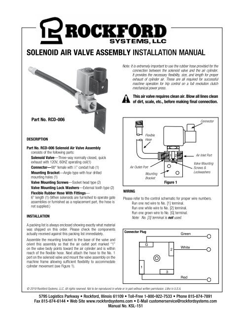
<strong>Air</strong> Outlet Port<br />
Flexible<br />
Hose<br />
Mounting<br />
Bracket<br />
Figure 1<br />
<strong>Air</strong> Inlet Port<br />
<strong>Valve</strong> Mounting<br />
Screws &<br />
Lockwashers<br />
Please refer to the control schematic for proper wire numbers.<br />
Run one red wire to No. [1] terminal.<br />
Run one white wire to No. [2] terminal.<br />
Run one green wire to No. [G] terminal.<br />
Note: No. [3] terminal is not used.<br />
A packing list is always enclosed showing exactly what material<br />
was shipped on this order. Please check the components<br />
actually received against this packing list immediately.<br />
Connector Plug<br />
Green<br />
Assemble the mounting bracket to the base of the valve and<br />
orient this assembly so that the air outlet port marked “1”<br />
on the valve body points toward the air cylinder and is within<br />
reach of the flexible hose. Next attach the hose to the No. 1<br />
port on the solenoid valve and mount the valve assembly on the<br />
machine frame allowing sufficient flexibility to accommodate<br />
cylinder movement (see Figure 1).<br />
1<br />
G<br />
3<br />
2<br />
White<br />
Red<br />
© 2019 Rockford Systems, LLC. All rights reserved. Not to be reproduced in whole or in part without written permission. Litho in U.S.A.<br />
5795 Logistics Parkway • Rockford, Illinois 61109 • Toll-Free 1-800-922-7533 • Phone 815-874-7891<br />
Fax 815-874-6144 • Web Site www.rockfordsystems.com • E-Mail customerservice@rockfordsystems.com<br />
<strong>Manual</strong> No. <strong>KSL</strong>-<strong>151</strong>
REPLACEMENT PARTS<br />
<strong>Solenoid</strong> <strong>Air</strong> <strong>Valve</strong><br />
1A<br />
1B<br />
Item Part No. Description<br />
1 RCD-047 <strong>Solenoid</strong> <strong>Valve</strong><br />
2<br />
1A — Nut - Metric Thread M20 x 1<br />
1B — WaveWasher<br />
1C RCD-004 Coil - 120V, 60Hz<br />
1D<br />
1E<br />
1F<br />
1C<br />
1D RCD-016 Plunger Repair Kit including<br />
Parts 1E - Spring and 1F -<br />
Plunger Body<br />
1E — Plunger Spring<br />
1F — Plunger Body<br />
2 RCS-037 Connector<br />
3 RCD-011 Mounting Bracket<br />
6<br />
3<br />
5<br />
4<br />
4 FSC-019 Cap Screw (2) 10-24 x 3 ⁄8”<br />
Socket Head<br />
5 FST-510 Lock Washer (2) No. 10<br />
External Tooth<br />
6 RCS-009 Hose - Flexible (6” Long)<br />
This equipment is specifically chosen for this appliction and must not be replaced except by an exact<br />
replacement. If repairs are required, use only the above referenced parts.<br />
WARRANTY, DISCLAIMER AND LIMITATION OF LIABILITY<br />
WARRANTY<br />
Rockford Systems, LLC warrants that this product will be free from defects in material and workmanship for a period of 12 months from the date of<br />
shipment thereof. ROCKFORD SYSTEMS LLC’s OBLIGATION UNDER THIS WARRANTY IS EXPRESSLY AND EXCLUSIVELY LIMITED to repairing or replacing such<br />
products which are returned to it within the warranty period with shipping charges prepaid and which will be disclosed as defective upon examination<br />
by Rockford Systems, LLC. This warranty will not apply to any product which will have been subject to misuse, negligence, accident, restriction and use<br />
not in accordance with Rockford Systems, LLC’s instructions or which will have been altered or repaired by persons other than the authorized agent or<br />
employees of Rockford Systems, LLC. Rockford Systems, LLC’s warranties as to any component part is expressly limited to that of the manufacturer of the<br />
component part.<br />
DISCLAIMER<br />
The foregoing Warranty is made in lieu of all other warranties, expressed or<br />
implied, and of all other liabilities and obligations on the part of Rockford<br />
Systems, LLC, including any liability for negligence, strict liability, or<br />
otherwise, and any implied warranty of merchantability or fitness for a<br />
particular purpose is expressly disclaimed.<br />
LIMITATION OF LIABILITY<br />
Under no circumstances, including any claim of negligence, strict liability, or otherwise,<br />
shall Rockford Systems, LLC be liable for any incidental or consequential damages, or<br />
any loss or damage resulting from a defect in the product of Rockford Systems, LLC.<br />
SAVIM/0619


