Operator Manual: #DL3100 Dualine Spray System - Bijur Delimon
Operator Manual: #DL3100 Dualine Spray System - Bijur Delimon
Operator Manual: #DL3100 Dualine Spray System - Bijur Delimon

Create successful ePaper yourself
Turn your PDF publications into a flip-book with our unique Google optimized e-Paper software.
<strong>Operator</strong>s <strong>Manual</strong><br />
DL3100<br />
<strong>Dualine</strong> ® Automatic <strong>Spray</strong> <strong>System</strong>s<br />
Installation, Operation, Parts List<br />
DL3100 r#2
<strong>Dualine</strong> series - AUTOMATIC SPRAY LUBRICATING SYSTEMS<br />
TABLE OF CONTENTS<br />
Introduction. . . . . . . . . . . . . . . . . . . . . . . . . . . . . . . . . . . . . . . . . . . . . . . . . . . . . . . . . . . . . . . . . . . . 2<br />
Typical system (Pump close to valve panel) . . . . . . . . . . . . . . . . . . . . . . . . . . . . . . . . . . . . . . . . . 3<br />
<strong>System</strong> - Sequence. . . . . . . . . . . . . . . . . . . . . . . . . . . . . . . . . . . . . . . . . . . . . . . . . . . . . . . . . . . . . . . 3<br />
Typical <strong>System</strong> (Pump remote from valve panel) . . . . . . . . . . . . . . . . . . . . . . . . . . . . . . . . . . . . 4<br />
Central Pumping Stations . . . . . . . . . . . . . . . . . . . . . . . . . . . . . . . . . . . . . . . . . . . . . . . . . . . . . . . . 5<br />
Valve Panels . . . . . . . . . . . . . . . . . . . . . . . . . . . . . . . . . . . . . . . . . . . . . . . . . . . . . . . . . . . . . . . . . . . . 6<br />
Lance Design . . . . . . . . . . . . . . . . . . . . . . . . . . . . . . . . . . . . . . . . . . . . . . . . . . . . . . . . . . . . . . . . . . . 7<br />
SC400 Controller. . . . . . . . . . . . . . . . . . . . . . . . . . . . . . . . . . . . . . . . . . . . . . . . . . . . . . . . . . . . . . . . 8<br />
Air Requirements . . . . . . . . . . . . . . . . . . . . . . . . . . . . . . . . . . . . . . . . . . . . . . . . . . . . . . . . . . . . . . . 9<br />
SC1-2 <strong>Spray</strong> Control Valves - Dimensions & Parts . . . . . . . . . . . . . . . . . . . . . . . . . . . . . . . . . . 10<br />
SC1-2 <strong>Spray</strong> Control Valves - Operation & Adjustment. . . . . . . . . . . . . . . . . . . . . . . . . . . . . . 11<br />
SC1-2 <strong>Spray</strong> Control Valves - Conversion For After Blow . . . . . . . . . . . . . . . . . . . . . . . . . . . . 12<br />
Installation Instructions . . . . . . . . . . . . . . . . . . . . . . . . . . . . . . . . . . . . . . . . . . . . . . . . . . . . . . . . . 13<br />
Location For Valve Panels And <strong>Spray</strong> Lance. . . . . . . . . . . . . . . . . . . . . . . . . . . . . . . . . . . . . . . . 14<br />
Startup And Maintenance Procedures . . . . . . . . . . . . . . . . . . . . . . . . . . . . . . . . . . . . . . . . . . . . . 15<br />
<strong>System</strong> Diagnosis. . . . . . . . . . . . . . . . . . . . . . . . . . . . . . . . . . . . . . . . . . . . . . . . . . . . . . . . . . . . . . . 16<br />
INTRODUCTION<br />
The spray systems described in this bulletin are used to lubricate large gear and pinion sets such as found on ball mills,<br />
rod mills, kilns, etc. Each systems includes an air operated pumping station, a measuring valve panel, a spray nozzle,<br />
electrical controls and a number of optional features.<br />
Gear face widths of 2" to 42" can be lubricated with nozzles and nozzle spacing designed accordingly. Since <strong>Bijur</strong><br />
<strong>Delimon</strong> gear spray systems operate intermittently they can be thought of as film maintaining devices. The<br />
electrical controls provide broad cycling flexibility as well as fault monitoring and after blow to purge the nozzles.<br />
Illustrations and specifications are not binding in detail.<br />
Designs are subject to modification and improvement without notice.<br />
2
<strong>Dualine</strong> series - AUTOMATIC SPRAY LUBRICATING SYSTEMS<br />
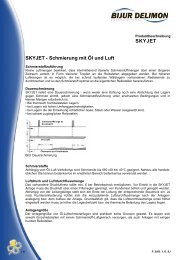
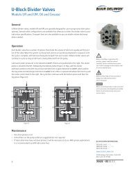
TYPICAL SYSTEM (Pump Close To Valve Panel)<br />
Figure - 1<br />
SEQUENCE OF OPERATION (<strong>System</strong> Shown in Fig.1)<br />
1. SC400 times out, opening the two solenoid air valves. The pump starts. A measured volume of lubricant<br />
discharges from each of the measuring valves to its spray nozzle. Air flows thru the air manifold to the<br />
spray nozzles, atomizing the lubricant to a penetrating spray.<br />
2. When each measuring valve has discharged once to its spray nozzle, system pressure begins to increase until<br />
at a predetermined point, it shifts the reversing valve; (Factory set @ 1500 psi)<br />
Reversing valve limit switch is operated closing the pump solenoid air valve, but a time delay device in the<br />
SC400 keeps the nozzle solenoid air valve open for a preset time period after lube flow stops. The air<br />
thoroughly cleanses the nozzles.<br />
Lube pressure in the system is relieved to reservoir by the reversing valve and alternate supply line is readied<br />
for pressurizing during next pumping cycle when the foregoing sequence is repeated.<br />
NOTE: For component part numbers, refer to fig's. 2 and 3.<br />
3
<strong>Dualine</strong> series - AUTOMATIC SPRAY LUBRICATING SYSTEMS<br />
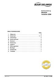
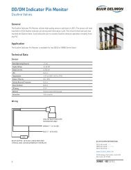
SCHEMATIC - TYPICAL SYSTEM (Pump Remote From Valve Panel)<br />
Figure - 2<br />
SYSTEM DETAILS AND PART NUMBERS<br />
ITEM # PART NUMBER QTY. DESCRIPTION<br />
1 9120 1 120lb Air Operated Barrel Pump<br />
2 DR460A 1 Reversing Valve<br />
3 LD7767CA1 1 Air Control Panel<br />
*4 U623 1 Air Pressure switch<br />
5 200275 1 Lube Supply Hose Kit (72")<br />
6 200277 1 Relief Hose Kit (72")<br />
7 200325 1 Air hose Kit (72")<br />
8 U1929D (OIL ONLY) 2 2-Way Line Checks<br />
9 BY USER 1 Supply Line Pipe or Hose to Panel<br />
*10 F1194G 1 Air Regulator<br />
11 LD12361V6 1 Valve Panel<br />
12 LD9327-XXXXX 1 <strong>Spray</strong> Lance<br />
13 SC400 1 Timer Control<br />
* Note: Items 4 & 10 sold separately<br />
Refer to Fig. 3 for pumping station details and part numbers. (Page 5)<br />
The spray system layout shown in (Fig.2) provides guidelines for installations where the pump, reversing valve and<br />
controls cannot be located close to the valve panel. To assure good pressure distribution under various operating<br />
temperature conditions, two pipe supply lines are run from the reversing calve to within 30" of the valve panel. Two<br />
36" hose assemblies are used to connect to the valve panel. The size of the piping for the supply lines can be selected<br />
from the table in page 13(Fig. 15).<br />
4
<strong>Dualine</strong> series - AUTOMATIC SPRAY LUBRICATING SYSTEMS<br />
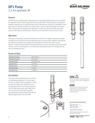
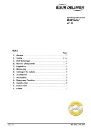
CENTRAL PUMPING STATION<br />
Figure - 3<br />
ITEM PART NO. DESCRIPTION<br />
1 9120 120 LB Air Operated Barrel Pump<br />
2 DR460A Reversing Valve<br />
3 LD7767CA1 Air Control Panel<br />
4 U623 Air Pressure Switch<br />
5 200275 Lube Supply Hose Kit (72")<br />
6 200277 Relief Hose Kit (72")<br />
7 200325 Air Hose Kit (72")<br />
8 U1929D (OIL ONLY) 2-Way Line Checks<br />
NOTE:<br />
A. The 9120 pump for 120 pound drums is recommended where solvent cut-back lubricants are used. This is to<br />
necessitate frequent drum changes to prevent drying and hardening of the lubricant. The 9400 pump for 400 pound<br />
drums is available if drying and hardening of the lubricant is not a problem.<br />
B. A U623 pressure switch (Item 4) is used to give warning of low pressure and is an optional feature.<br />
C. All Central Pumping Stations are for 120 Volts, 60 Cycle, but other voltages and frequencies are available.<br />
Electrical timing devices are described on page 8.<br />
D. The U1929D two way checks are needed only if the lubricants have fluid characteristics.<br />
5
<strong>Dualine</strong> series - AUTOMATIC SPRAY LUBRICATING SYSTEMS<br />
VALVE PANELS<br />
18<br />
1/2" NPT<br />
AIR SUPPLY<br />
7<br />
23<br />
19<br />
34.0<br />
.62 32.75<br />
3/4" DIAMETER THRU<br />
8 HOLES<br />
17.88<br />
16<br />
START<br />
20<br />
10<br />
21<br />
14 12<br />
12.88<br />
15.0<br />
15<br />
6.00<br />
1.5<br />
11<br />
2.5 APPROX.<br />
3/8" NPSF<br />
LUBE INLET<br />
24 6<br />
5<br />
24 6<br />
22<br />
9<br />
24<br />
17<br />
6<br />
24<br />
4<br />
13<br />
1/2" NPT<br />
CONDUIT CONNECTION<br />
3<br />
2<br />
FIGURE - 4<br />
VALVE PANEL LD12361V8 PARTS LIST<br />
ITEM # QTY. PART NO. DESCRIPTION<br />
1 4 201222 Hose Assembly with Adapter - 30" long<br />
2 1 201502 Kit - Air Supply Hose - 36" long<br />
3 1 201595 Valve Solenoid 2-way NC 3/4"NPT 50/60Hz<br />
4 8 U1732F Cover Indicator Stem<br />
5 4 DM62100A <strong>Dualine</strong> Valve<br />
6 4 201223 Hose Assembly with Adapter - 36" long<br />
7 1 F6024MD Filter Air Line 1/2"NPT Auto Drain<br />
8 1 LD9340V8P Plate - Mounting<br />
9 12 U81D3 Sleeve and Nut 3/8" tube x 3/8"NPT<br />
10 1 U101D2 Nipple 1/2"NPT x 1-1/8" long<br />
11 1 U101E1 Nipple 3/4"NPT x 1-3/8" long<br />
12 1 U101E19 Nipple 3/4"NPT x 7" long<br />
13 1 U11354 Elbow Reducing Pipe 3/4" x 1/2"<br />
14 1 U11654 Reducing Coupling<br />
15 4 U119CC Plug 3/8"NPT<br />
16 4 U204C15 Screw Hex Head Cap 3/8"-16 x 5/8" long<br />
17 8 U206K6 Screw Fillet Head Machine 5/16"-18 x 2-1/2" long<br />
18 4 U207G3 Screw Round Head Machine #10-24 x 1/2" long<br />
19 4 U213C Washer Lock #10<br />
20 4 U213G Washer Lock 3/8"<br />
21 2 U2685 Bracket Mounting 3/4"NPT<br />
22 .75' U424E6 Tubing Steel 3/8" O.D.<br />
23 1 LE9629B Pushbutton 'start'<br />
24 8 U1104B Ell Street 1/4"NPT<br />
Shown in Fig. 4 is a typical measuring valve panel(Panel assembly#LD12361V8). This panel has measuring valves to serve<br />
8 nozzles. Panels having from 1 to 8 measuring valves are available as shown in Table 1. All panels have outside dimensions<br />
of 34" X 15". The only variable on each panel is the number of measuring valves(one to eight). DM60 size measuring<br />
valves are standard on the panels, however, smaller capacity measuring valves can be supplied if required.<br />
6<br />
3.94<br />
.25<br />
1.81<br />
3.94<br />
3.94 1.81 3.94 1.81<br />
1.81<br />
7.63<br />
TABLE 1.<br />
AVAILABLE PANELS<br />
PANEL<br />
NUMBER<br />
NUMBER SPRAY NOZZLES<br />
LD12361V1<br />
1<br />
LD12361V2<br />
2<br />
LD12361V3<br />
3<br />
LD12361V4<br />
4<br />
LD12361V5<br />
5<br />
LD12361V6<br />
6<br />
LD12361V7<br />
7<br />
LD12361V8 8
<strong>Dualine</strong> series - AUTOMATIC SPRAY LUBRICATING SYSTEMS<br />
SPRAY LANCE - MODEL LD-9327<br />
Model LD-9327 spray lances described below include spray nozzles in which air under pressure atomizes lubricant from<br />
the valve panels and sprays it onto the gear face. Note that guard width must be exactly 3" wider than gear face width.<br />
Contact factory for special applications.<br />
A<br />
A<br />
U1078<br />
1-1/2"<br />
PIPE CAP<br />
B6519<br />
"B"<br />
"B"<br />
"B"<br />
"A"<br />
U922C U1104B U101B1<br />
"B"<br />
1-1/2" STEEL PIPE<br />
1.5" FORGED STEEL SLIP ON FLANGE<br />
(NOT FURNISHED BY BDI)<br />
U424C6<br />
GEAR GUARD<br />
3/8"OD TUBING<br />
Group 1 - Assembly Numbers and Dimensions<br />
ASSEMBLY<br />
PART #<br />
LD93271020S<br />
LD93271030S<br />
LD93271040S<br />
LD93271050S<br />
LD93271060S<br />
LD93272070S<br />
LD93272080S<br />
LD93272090S<br />
LD93272100S<br />
LD93272110S<br />
LD93273120S<br />
LD93273130S<br />
LD93273140S<br />
LD93273150S<br />
LD93273160S<br />
LD93274170S<br />
LD93274180S<br />
LD93274190S<br />
LD93274200S<br />
LD93274210S<br />
LD93275220S<br />
LD93275230S<br />
LD93275240S<br />
LD93275250S<br />
LD93276260S<br />
LD93276270S<br />
LD93276280S<br />
LD93276290S<br />
LD93276300S<br />
LD93276310S<br />
LD93277320S<br />
LD93277330S<br />
LD93277340S<br />
LD93277350S<br />
LD93277360S<br />
LD93277370S<br />
LD93278380S<br />
LD93278390S<br />
LD93278400S<br />
LD93278410S<br />
LD93278420S<br />
GEAR<br />
FACE<br />
WIDTH<br />
2"<br />
3"<br />
4"<br />
5"<br />
6"<br />
7"<br />
8"<br />
9"<br />
10"<br />
11"<br />
12"<br />
13"<br />
14"<br />
15"<br />
16"<br />
17"<br />
18"<br />
19"<br />
20"<br />
21"<br />
22"<br />
23"<br />
24"<br />
25"<br />
26"<br />
27"<br />
28"<br />
29"<br />
30"<br />
31"<br />
32"<br />
33"<br />
34"<br />
35"<br />
36"<br />
37"<br />
38"<br />
39"<br />
40"<br />
41"<br />
42"<br />
GUARD<br />
WIDTH<br />
4.5"<br />
5.5"<br />
6.5"<br />
7.5"<br />
8.5"<br />
9.5"<br />
10.5"<br />
11.5"<br />
12.5"<br />
13.5"<br />
14.5"<br />
15.5"<br />
16.5"<br />
17.5"<br />
18.5"<br />
19.5"<br />
20.5"<br />
21.5"<br />
22.5"<br />
23.5"<br />
24.5"<br />
25.5"<br />
26.6"<br />
27.5"<br />
28.5"<br />
29.5"<br />
30.5"<br />
31.5"<br />
32.5"<br />
33.5"<br />
34.5"<br />
35.5"<br />
36.5"<br />
37.5"<br />
38.5"<br />
39.5"<br />
40.5"<br />
41.5"<br />
42.5"<br />
43.5"<br />
44.5"<br />
NO. OF<br />
SPRAY<br />
NOZZLES<br />
1<br />
1<br />
1<br />
1<br />
1<br />
2<br />
2<br />
2<br />
2<br />
2<br />
3<br />
3<br />
3<br />
3<br />
3<br />
4<br />
4<br />
4<br />
4<br />
4<br />
5<br />
5<br />
5<br />
5<br />
6<br />
6<br />
6<br />
6<br />
6<br />
6<br />
7<br />
7<br />
7<br />
7<br />
7<br />
7<br />
8<br />
8<br />
8<br />
8<br />
8<br />
DIMENSIONS<br />
B C<br />
A +/- +/-<br />
1/16" 1/16"<br />
8" - 2.25<br />
10" - 2.75<br />
11" - 3.25<br />
12" - 3.75<br />
13" - 4.50<br />
14" 4.00 2.25<br />
15" 4.50 3.00<br />
16" 4.50 3.50<br />
17" 5.00 3.75<br />
18" 5.25 4.13<br />
19" 4.38 2.87<br />
20" 4.38 3.37<br />
21" 4.68 3.57<br />
22" 5.00 3.75<br />
23" 5.25 4.00<br />
24" 4.50 3.00<br />
25" 4.50 3.50<br />
26" 4.75 3.75<br />
27" 5.00 4.00<br />
28" 5.25 3.88<br />
29" 4.50 3.25<br />
30" 4.75 3.50<br />
31" 5.00 3.75<br />
32" 5.25 4.00<br />
33" 4.38 3.30<br />
34" 4.38 3.80<br />
35" 4.68 3.55<br />
36" 4.68 4.05<br />
37" 5.00 3.75<br />
38" 5.25 3.63<br />
39" 4.38 4.11<br />
40" 4.68 3.71<br />
41" 5.00 3.25<br />
42" 5.00 3.75<br />
43" 5.25 3.50<br />
44" 5.25 4.00<br />
45" 4.68 3.87<br />
46" 4.80 3.95<br />
47" 5.00 3.75<br />
48" 5.10 3.90<br />
49" 5.25 3.88<br />
7<br />
"B"<br />
8.0" 6.7"<br />
5.75"<br />
1.75"<br />
"B"<br />
B6514<br />
GEAR GUARD<br />
1.67"<br />
3.0"<br />
1.22"<br />
"C"<br />
9.0"<br />
7.75"<br />
1.0"<br />
4.75"<br />
VIEW A-A<br />
U1103B<br />
1/2”NPT<br />
AIR INLET<br />
1/4”NPT<br />
LUBE INLET<br />
LUBE HOSE - REF.<br />
60° 6.75"<br />
4.25"<br />
.625"<br />
Ø.75"(X4)<br />
NOTE:<br />
"S" series spray lances are shipped with<br />
round spray nozzles installed. Flat spray<br />
nozzle set is also included with each spray<br />
lance.
<strong>Dualine</strong> series - AUTOMATIC SPRAY LUBRICATING SYSTEMS<br />
SC400 MULTI-FUNCTION CONTROLLER/MONITOR<br />
General<br />
The SC400 Controller is a full featured lubrication control, offering “two plus one”<br />
functionality. The controller has the ability to operate a single pump and two zone valves<br />
(e.g. frequent/infrequent lubrication cycles) or two separate pumps (e.g. one oil pump &<br />
one grease pump). For single zone systems, the SC400 Controller also offers two intervals<br />
(e.g. weekday /weekend). The controller can activate a fi ll pump as needed to maintain<br />
proper fl uid levels in the oil or grease reservoir.<br />
Features<br />
+ 2 zone operation (for Progressive, Injector and <strong>Dualine</strong> Hydraulic systems).<br />
+ IP56 enclosure, constructed of molded polyester fi berglass.<br />
+ CE approved.<br />
+ Four supported languages (English, French, Spanish, German).<br />
+ Pump output may be powered externally or via control power.<br />
+ Valve A, Valve B and Fill pump may be powered exrternally or via controller.<br />
+ Critical Inputs accept PNP, NPN or mechanical switches.<br />
+ 500 mA of 24 VDC is available to power customer's accessories.<br />
+ Primary alarm inputs may be programmed for N.O. or N.C. functionality.<br />
+ Machine watchdog and cycle monitoring.<br />
+ Pause (standby), jog (manual operation).<br />
+ Accepts all BDI electric reversing valves and cycle/pressure/"end-of-line" switches. Refer to the following documents for more info:<br />
Technical Data<br />
Input Voltage 85 to 265 VAC, 50/60 Hz<br />
Output Rating (Line A & B) 8 amp (90 to 250 VAC)<br />
Enclosure Rating IP-56<br />
Idle Time Range 1 second to 100 days<br />
Machine Cycle Counts 1 to 999,999 Counts (30 counts/second at 50% duty cycle)<br />
Watchdog Timer 1 second to 60 minutes<br />
Monitor Time 1 second to 24 hours<br />
Cycle Counts On 1 to 999 counts<br />
Over Counts 0 to 9<br />
Net Weight 5 lb<br />
Length x Width x Height 12.3” x 9.2” x 5”<br />
Fault Relay Contacts 5 amp<br />
8<br />
+ Datasheet #35980: SC400 Controller
<strong>Dualine</strong> series - AUTOMATIC SPRAY LUBRICATING SYSTEMS<br />
SYSTEM AIR REQUIREMENTS<br />
A free air volume of V a cubic feet, calculated by the equation<br />
below, should be provided for each lube cycle. This is twice<br />
the theoretical air volume needed to operate both pump and<br />
nozzle. A lube cycle is defined on page 3.<br />
V a = 2V 1 (T 1 +T 2 )+2V 2 (T 1 +T 2 +T 3 )<br />
Where:<br />
V 1 = Free air volume used by the pump*.<br />
assume = 5.0 cfm.<br />
V 2 = Free air volume used by the nozzles in cu.ft. per minute<br />
see Fig. 9.<br />
T 1 = Time in minutes to compress lube in distribution lines.<br />
see Fig. 10.<br />
T 2 = Time in minutes required by a pump to discharge lube<br />
from the nozzles during one count. See Fig. 9.<br />
T 3 = Time in minutes for air to clean lube from nozzles after<br />
discharge. Allow 0.50 minutes.<br />
Example: Find the free air volume needed by the spray system shown in Fig.2. (Page<br />
4) The lance has six U922C nozzles. The valve panel has six valves - DM62 valve<br />
blocks. Distribution lines consist of 100' of 1" pipe. The system is to be operated<br />
four times an hour.<br />
V a = 2 x 5 (.18 + 0.09) + 2 x 81 (.18 + 0.09 + .5) = 127cu.ft. per lube cycle<br />
Volume of free air required for one hour is: 4 x 127 = 508 cu.ft.<br />
9<br />
NO. OF<br />
NOZZLES<br />
T2<br />
FOR DD5X FOR DM6X<br />
V2 (cfm)<br />
1 .005 .015 13.5<br />
2 .010 .030 27.0<br />
3 .015 .045 40.5<br />
4 .020 .060 54.0<br />
5 .025 .075 67.5<br />
6 .030 .090 81.0<br />
7 .035 .105 94.5<br />
8 .040 .120 108.0<br />
Fig. 9 - Values for T2 and V2 .<br />
LUBE COMPRESSION TIME “T2” IN MINUTES<br />
.80<br />
.70<br />
.60<br />
.50<br />
.40<br />
.30<br />
.20<br />
.10<br />
1-1/2” PIPE<br />
1-1/4” PIPE<br />
1” PIPE<br />
3/4” PIPE<br />
1/2” PIPE<br />
0<br />
0 50 100 150 200<br />
LENGTH OF DISTRIBUTION LINES IN FEET<br />
Fig. 10 - Lube compession time “T1”<br />
(based on 1% compressibility of lubricant).<br />
*The pump is assumed to be operating with air pressure regulator set between 80 and 100 psi and a line back pressure<br />
of 1000 psi (the line back pressure is usually much lower). Lube volume discharged by the pump is assumed to be 40<br />
cubic inches per minute.
<strong>Dualine</strong> series - AUTOMATIC SPRAY LUBRICATING SYSTEMS<br />
BDI SPRAY CONTROL VALVE & NOZZLE ASSEMBLIES<br />
APPLICATION: SC1-2 spray control valves are used on manually operated spray systems, automatic gear spray systems<br />
on shovels and drag lines, and on older gear spray panels.<br />
COMPONENT ASSEMBLIES<br />
1. SC1 Series spray control valve<br />
1-3/32”<br />
21/64”(X2)<br />
(identical for all assemblies)<br />
1-3/8”<br />
1-3/8”<br />
1/2”<br />
1”<br />
2<br />
1<br />
3/8”<br />
1” 1”<br />
2”<br />
1/2”<br />
1-3/4”<br />
1/2”<br />
2-3/4”<br />
3-27/32”<br />
11/16” TO CENTERLINE<br />
OF 1/4”NPTF LUBE UNIT<br />
HOW TO ORDER EXAMPLES:<br />
A. <strong>Spray</strong> nozzle setup if known: One SC1-2 spray control valve with spray nozzle setup.<br />
(Specify correct spray nozzle setup, whether U943A, C or F.)<br />
B. SC1-2 w/After Blow: Order P.N. SPR13241B (Order U943 separately)<br />
C. <strong>Spray</strong> nozzle setup:<br />
1. U943A - for light oil.<br />
2. U943C - for oil or grease - recommended for most spray applications.<br />
3. U943F - used when flat spray pattern is desired such as spraying wire rope.<br />
SC1-2 SPRAY CONTROL VALVE WITH<br />
U943 SPRAY NOZZLE SET-UP<br />
ITEM # PART NO. DESCRIPTION<br />
*1 N/A Valve Body<br />
*2 N/A Piston<br />
3 SC110061 Spring-Piston Stop<br />
4 SC110072 Air Check Valve Assy.<br />
**5<br />
Check Valve Body<br />
**6<br />
N/A<br />
Lock Nut<br />
**7 Spring<br />
**8 Quad Ring<br />
9 U204B6 5/16-18 x 1-3/4 Cap Scr.<br />
10 U213F 5/16 Lockwasher<br />
11 U219B 5/16-18 Hex Nut<br />
12 U230D 5/16" Check Ball<br />
19<br />
13 U943 <strong>Spray</strong> Nozzle Set Up<br />
20<br />
14 U1204D 7/16-20 Dr. Ret. Scr.<br />
13<br />
15 U1305G 7/16" Copper Washer<br />
18<br />
16 U1522D Closure Plug<br />
21<br />
17 U1526 Ball Retainer<br />
*Items 1 & 2 shown for reference only - not for resale.<br />
**Items must be purchased in item#4.<br />
U-943 SPRAY NOZZLE SET-UP<br />
10<br />
2. U943 spray nozzle setup<br />
(model selected depends on lubricant<br />
and application)<br />
NOTE:<br />
SC1-2 spray control valve and U943 spray<br />
nozzles are sold separately. Must purchase<br />
individually.<br />
ITEM<br />
U943A<br />
PART NO.<br />
U943C U943F<br />
NAME<br />
18 UX943A1 UX943C1 UX943C1 Fluid Nozzle<br />
19 UX943A2 UX943C2 UX943F2 Air Nozzle<br />
20 UX943A3 UX943A3 UX943A3 Hex Retainer<br />
21 UX943A4 UX943A4 UX943A4 Gasket<br />
5<br />
14<br />
7<br />
6 4<br />
17<br />
12<br />
8<br />
3<br />
2<br />
1<br />
15<br />
16
<strong>Dualine</strong> series - AUTOMATIC SPRAY LUBRICATING SYSTEMS<br />
BDI SPRAY CONTROL VALVE & NOZZLE ASSEMBLY<br />
HOW TO ADJUST MODEL SC1 SPRAY CONTROL VALVES<br />
SC1 valves are factory adjusted to function properly with NLGI #0 consistency lubricant. If other lubricants are used,<br />
the following adjustment may be needed to improve atomization or to eliminate nozzle burping at the start and end of<br />
the lube cycle.<br />
1. Pump to 1000 psi on the pressure gauge. Relieve system with the pump solenoid valve and then loosen locknut<br />
(item 6, page 10) at the air inlet and turn check valve body (5) clockwise until air slows thru spray nozzle (13).<br />
Finally turn check valve body counterclockwise until no air escapes.<br />
2. Repeat "1" several times if needed for good atomization. Then tighten locknut. Caution: To prevent a change in<br />
setting, hold check body firmly while tightening locknut.<br />
HOW SPRAY CONTROL VALVE & NOZZLE ASSEMBLIES OPERATE<br />
1. Lube under pressure fl ows thru port A into chamber<br />
B causing piston D to move toward ball E. this both<br />
unseats the ball and opens a port from chamber B to<br />
passage G.<br />
2. Air fl ows past ball E thru passage F and lube fl ows<br />
thru passage G. They meet in air nozzle H and produce<br />
a spray. Removal of the air nozzle will only produce a<br />
more concentrated spray.<br />
11<br />
H<br />
ASSEMBLY NOTES<br />
F<br />
G<br />
C<br />
E<br />
1/8” DIA.<br />
STEM<br />
THIS END<br />
When assembling an SC1 valve, install large (1/8" dia.) end of piston D toward ball as shown in figure.<br />
SCI PERFORMANCE DIAGNOSIS - (Valve fails to operate properly)<br />
Cause Repair<br />
1. Insuffi cient air supply. 1. Check pressure - should be 80psi minimum<br />
(not less than 60 psi during spray cycle)<br />
2. Incorrect setting of air control valve. 2. Re-adjust - see above for details.<br />
3. Clogged spray nozzle. 3. Wash with solvent and reassemble.<br />
4. Clogged spray control. 4. Remove pilot piston and clean it and the piston bore<br />
with solvent. Reassemble.<br />
D<br />
B<br />
A
<strong>Dualine</strong> series - AUTOMATIC SPRAY LUBRICATING SYSTEMS<br />
SCI CONVERSION - TO PROVIDE AFTER BLOW<br />
(FOR EXISTING SPRAY PANELS EQUIPPED WITH SC1 VALVES)<br />
STAINLESS<br />
STEEL BODY<br />
LUBRICANT<br />
SOCKET SET SCREW<br />
5/16”-18 X 5/16” LG.<br />
(LOCTITE THREADS)<br />
.257” DRILL<br />
5/16”-18 TAP<br />
AIR<br />
LUBE CROSSPORT<br />
TO NOZZLE<br />
FIGURE - 14<br />
12<br />
FLUID<br />
NOZZLE<br />
HEX<br />
RETAINER<br />
AIR NOZZLE<br />
(MUST ORDER<br />
SEPARATELY)<br />
AIR RELEASE<br />
VALVE BODY<br />
AIR ENTRY PORT<br />
TO NOZZLE<br />
JAMB<br />
NUT<br />
NOTES<br />
Existing spray panels equipped with SC1-2 spray control valves can be upgraded to incorporate after blow by employing<br />
the following procedure:<br />
1. Remove items (shown on page 10) numbers 2, 3, 8, 12, 17, 7 and 14.<br />
2. Drill piston bore .257" then tap 5/16"-18.<br />
3. Insert 5/16"-18 x 5/16" long set screw coated with Loctite thread locker.<br />
4. Insert solenoid air shut-off valve in air line to nozzles and wire in parallel with air operated barrel pump.<br />
5. Install time delay relay in control circuit to provide approximately 60 seconds after blow.<br />
CAN ORDER SC1-2 WITH AFTER BLOW FROM BDI. PART # SPR13241B. MUST ORDER AIR NOZZLE SEPARATELY(SEE PG 10)
<strong>Dualine</strong> series - AUTOMATIC SPRAY LUBRICATING SYSTEMS<br />
INSTALLATION INSTRUCTIONS<br />
INSTALLATION<br />
1. Pump Close To Valve Panel (See Page 3): In most installations of this type, hoses are used to make all air and<br />
lubricant connections. Hose lengths must be adequate to allow movement of the pump during lubricant drum<br />
changes.<br />
Clean inside of hoses thoroughly before installing to remove foreign material. Tighten all hose connections<br />
securely using a thread lubricant and sealant.<br />
2. Pump Remote From Valve Panel (See Page 4): Hoses are used to connect the air line to the pump and the pump<br />
to the reversing valve. Pipe is run from the reversing valve to within 30" of the valve panel with the final<br />
connection to the valve panel made with hose assemblies.<br />
Pipe size selection is important, as it will affect the operating pressure of the system. For guidance in selecting<br />
proper pipe size, see pipe sizing table in Figure 15.<br />
Pipe Sizing Table - Fig. 15<br />
(Pump Remote From Valve Panel)<br />
PIPE SIZE<br />
50° - 90°<br />
OPERATING TEMPERATURE (°F)<br />
32° - 50° 0° - 32°<br />
1/2 60 FT. 40 FT. 20 FT.<br />
3/4 - 60 FT. 30 FT.<br />
1 - - 40 FT.<br />
NOTE: Longer lengths and larger diameter pipe is not recommended due to the fact that the compressed volume<br />
of lubricant, within a pipe, causes the valve manifold to cycle after the pump shuts down. This can result in<br />
excessive consumption of lubricant and/or cause the SC400 control to fault.<br />
Clean pip thorougly before installation to remove all scale, chips, dirt and burrs. Install pipe in protected<br />
locations and firmly clamp in place. Pipe threads should be cut clean and free of burrs. Use a good thread<br />
lubricant and sealant. Use 3000 pound forged steel fittings and schedule 80 pipe. Pull all connections tight.<br />
3. For valve panel and spray lance locations - see page 14.<br />
4. The Lubricant: High quality open gear lubricants are readily available that can be pumped and sprayed at low<br />
temperatures without requiring heat. Be sure that the lubricant selected will remain pumpable at the minimum<br />
operating temperature that will be encountered.<br />
13
<strong>Dualine</strong> series - AUTOMATIC SPRAY LUBRICATING SYSTEMS<br />
INSTALLATION & LAYOUT<br />
INSTALLATION<br />
LOCATION FOR VALVE PANEL LD12361 AND SPRAY LANCES LD9327 AS SHOWN IN FIGS. 16 & 17.<br />
GEAR<br />
1-7/32”<br />
ANGLE OF<br />
SPRAY<br />
30° +/- 10°<br />
SPRAY LANCE LD9327<br />
8” +/- 1/2”<br />
SPRAY LANCE LD9327<br />
GEAR GUARD<br />
GEAR PITCH CIRCLE<br />
30° +/- 10°<br />
SPRAY<br />
PATTERN<br />
CENTERLINE<br />
FIGURE - 17<br />
14<br />
SPRAY LANCE LD9327<br />
FIGURE - 16<br />
PITCH CIRCLE - GEAR<br />
GEAR TOOTH<br />
CENTERLINE<br />
PITCH CIRCLE - PINION<br />
GEAR GUARD<br />
GEAR GUARD<br />
30° +/- 10°<br />
8” +/- 1/2”<br />
8” +/- 1/2”<br />
CENTERLINE<br />
SPRAY<br />
PATTERN<br />
GEAR GUARD<br />
1-7/32”
<strong>Dualine</strong> series - AUTOMATIC SPRAY LUBRICATING SYSTEMS<br />
START UP AND MAINTENANCE<br />
START UP PROCEDURE<br />
1. Program the SC400 controller in accordance with instructions given.<br />
2. Fill air line lubricator with light oil (SAE #10).<br />
3. Adjust pump air regulator to obtain 1800 psi pump line pressure.<br />
4. The DR4 reversing valve is set to reverse at 1500 psi at the factory.<br />
5. Set the air regulator for the spray nozzles to 60 - 80 psi. Re-adjust for best spray.<br />
6. To fi ll the two main supply lines to the measuring valves:<br />
a) Remove the pipe plugs from the last measuring valve.<br />
b) Start pump by pressing SC400 manual/reset button.<br />
c) Bleed (1) pint of lubrication from line 1 at the last measuring valve.<br />
d) Stop pump by pressing SC400 manual/reset button again.<br />
e) Insert pipe plug in last measuring valve (line that was purged).<br />
f) Start the pump again. Pressure will build up to operate the reversing valve.<br />
g) Follow steps c, d, and e for purging supply line 2.<br />
7. After purging both suply lines, the system is ready to operate. Cycle the system manually until the spray<br />
nozzles are operating properly and the gear face is being completly covered with lubricant.<br />
8. Coat the entire gear face (all teeth) with lubricant before starting up the mill.<br />
MAINTENANCE<br />
A. Too much water in the air fi lter drain bowl on the air control panel will make the fi lter ineffective and water will<br />
enter the pump. Empty it regularly, a drain cock is provided. If moisture in the air supply line requires frequent<br />
draining of the air fi lter we suggest installing automatic drain assembly.<br />
B. Be sure lube container has plenty of lubricant. Pumping from an empty drum may force air into system, causing<br />
diffi culty in building pressure.<br />
C. Use clean lubricant. Foreign matter might clog valve manifold.<br />
D. Keep line stainers clean. These are usually installed in the line leading to the valve manifold. Establish regular<br />
intervals for this service.<br />
E. Inspect entire system regularly including hose (replace if damaged), connections (they should be tight), and<br />
the gear (see that the teeth are being properly lubricated). Check spray pattern frequently by inserting a<br />
piece of cardboard in front of the spray nozzles while the system is operating. Complete coverage of the gear<br />
face is important.<br />
F. Completely clean the system with a fl ushing solvent every year or two to extend its life.<br />
15
<strong>Dualine</strong> series - AUTOMATIC SPRAY LUBRICATING SYSTEMS<br />
TROUBLE SHOOTING<br />
A. Pump doesn't operate*<br />
SYSTEM DIAGNOSIS<br />
CONDITION CAUSE REMEDY<br />
B. Pump operates but doesn't build<br />
pressure.<br />
C. Manifold valve indicator doesn't<br />
operate.<br />
1. Insuffi cient air supply. 1. Adjust air pressure to 40/50 psi.<br />
2. Timer control failing to operate<br />
solenoid shut-off.<br />
3. Lubricant has hardened in drum.<br />
16<br />
2. Check wiring of system timer according<br />
to instructions and SC400<br />
controller. Also check timer for<br />
proper programming.<br />
3. Use smaller sized drums - diluent<br />
in some lubricants tends to evaporate<br />
causing lubricant to harden.<br />
1. Reservoir empty.<br />
1. Check and renew lubricant supply.<br />
Purge air from lines.<br />
2. Broken line. 2. Repair or replace as necessary.<br />
3. Air in system.<br />
3. Bleed lines and valves as described<br />
on page 15.<br />
1. Lack of pressure. 1. Repair - see condition B.<br />
2. Incorrect operation of reversing<br />
valve..<br />
3. Dirt in <strong>Dualine</strong> measuring valve.<br />
2. Check valve condition by "shortcircuiting"<br />
it with two 3/8" pipe plugs<br />
installed in reversing valve discharge<br />
ports. Start air-operated barrel<br />
pump, and reversing valve will oscillate<br />
if properly adjusted for type of<br />
system. Clean any strainer in lines<br />
every six months.<br />
3. Remove inlet bore plugs and piston.<br />
Clean bore by pouring solvent through<br />
it. Clean piston and re-assemble.<br />
4. Locate obstruction, remove line<br />
4. Plugged discharge line.<br />
and blow clean, or replace faulty section.<br />
*For more information on the air operated barrel pump, see Data Sheet # 35993.
<strong>Dualine</strong> series - AUTOMATIC SPRAY LUBRICATING SYSTEMS<br />
Notes<br />
17
<strong>Dualine</strong> series - AUTOMATIC SPRAY LUBRICATING SYSTEMS<br />
Notes<br />
18
<strong>Dualine</strong> series - AUTOMATIC SPRAY LUBRICATING SYSTEMS<br />
Notes<br />
19
Series Progressive<br />
<strong>Dualine</strong><br />
Oil Recovery Unit<br />
Whatever your automatic<br />
lube requirement…<br />
We have the solution!<br />
SureFire-PDI<br />
Injectors<br />
Flowmeters<br />
Refillable Re<br />
Single Sin Point<br />
Let 80+ Years Of Experience Design Your Next Lube <strong>System</strong><br />
BDI has been a manufacturer of automatic lubricating systems for over 80 years. We offer a complete line of pumps, valves, controllers,<br />
and accessories. Our pump line includes manual, air, electric, and hydraulic actuated models. Our valve offering is the most comprehensive<br />
in the industry. We manufacture oil and grease <strong>Dualine</strong> valves, series progressive modular valves, and injectors. We also offer air/oil mixing<br />
modules, oil flow meters, and single point lubricators.<br />
BIJUR DELIMON INTERNATIONAL<br />
2685 Airport Road Kinston, NC 28504<br />
Tel. 800-227-1063 Fax: 252-527-9232<br />
Website: www.bijurdelimon.com<br />
Your local distributor:<br />
BIJUR ® DELIMON ® -DENCO FARVAL ® LUBESITE ®<br />
DL3100-R2 (10/12)