electrical data - Mitsubishi Heavy Industries
electrical data - Mitsubishi Heavy Industries
electrical data - Mitsubishi Heavy Industries

Create successful ePaper yourself
Turn your PDF publications into a flip-book with our unique Google optimized e-Paper software.
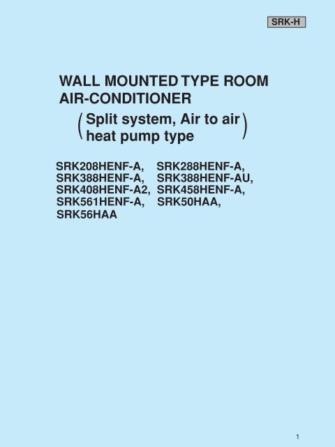
WALL MOUNTED TYPE ROOM<br />
AIR-CONDITIONER<br />
( Split system, Air to air)<br />
heat pump type<br />
SRK208HENF-A, SRK288HENF-A,<br />
SRK388HENF-A, SRK388HENF-AU,<br />
SRK408HENF-A2, SRK458HENF-A,<br />
SRK561HENF-A, SRK50HAA,<br />
SRK56HAA<br />
SRK-H<br />
1
2<br />
SRK-H<br />
CONTENTS<br />
GENERAL INFORMATION......................................................................................3<br />
Specific features ..............................................................................................3<br />
How to read the model name ..........................................................................3<br />
SELECTION DATA...specifications................................................................4 ~ 12<br />
Range of usage & limitations........................................................................13<br />
Exterior dimensions...............................................................................14 ~ 17<br />
Piping system.........................................................................................18 ~ 21<br />
ELECTRICAL DATA......................................................................................23 ~ 28<br />
OUTLINE OF OPERATION CONTROL BY MICROCOMPUTER ........................29<br />
Details of operation control .................................................................30 ~ 41<br />
APPLICATION DATA...........................................................................................42<br />
Selection of location for installation ...........................................................43<br />
Installation of indoor unit.....................................................................44 ~ 46<br />
Installation of outdoor unit...................................................................46 ~ 48<br />
Refrigerant piping.........................................................................................47<br />
Test run..........................................................................................................48<br />
Precautions for wireless remote controller installation<br />
and operation .......................................................................................49<br />
MAINTENANCE DATA.........................................................................................50<br />
Trouble shooting..........................................................................................50<br />
Servicing.......................................................................................................54<br />
Power supply remote operation..................................................................55
3.1 GENERAL INFORMATION<br />
3.1.1 Specific features<br />
The “<strong>Mitsubishi</strong> Daiya” room air conditioner: SRK series are of split and wall mounted type and the unit consists of indoor unit and<br />
outdoor unit with refrigerant precharged in factory. The indoor unit is composed of room air cooling or heating equipment with opera-<br />
tion control switch and the outdoor unit is composed of condensing unit with compressor.<br />
(1) Remote control flap<br />
The flap can be automatically controlled by operating wireless remote control.<br />
• AUTO (Natural flow) : Flap operation is automatically control.<br />
• Swing : This will swing the flap up and down.<br />
• Memory flap : Once the flap position is set, the unit memorizes the position and continues to operate at the same<br />
(2) Automatic Operation<br />
position from the next time.<br />
When the remote control switch is set on “auto”, it will either automatically decide operation mode such as cooling, heating and<br />
thermal dry, or operate in the operation mode before it has been turned to automatic control.<br />
(3) Self diagnosis Function<br />
We are constantly trying to do better service to our customers by installing such judges that show abnormality of operation as<br />
follows.<br />
TIMER lamp is<br />
light up.<br />
RUN lamp is light<br />
up.<br />
3.1.2 How to read the model name<br />
Example : SR K 50 8 H EN F - A<br />
Indoor Unit<br />
SR K 50 AA<br />
t<br />
Series No.<br />
RUN lamp is flashing.<br />
(1 Time flash.)<br />
RUN lamp is flashing.<br />
(2 Time flash.)<br />
RUN lamp is flashing.<br />
(6 Time flash.)<br />
TIMER lamp is flashing.<br />
(5 Time flash.)<br />
Product capacity<br />
Wall mounted type<br />
Split type room<br />
air-conditioner<br />
CE marking model<br />
Flare connecting<br />
Applicable power source …… See the specifications<br />
Heat pump type<br />
Series No.<br />
Product capacity<br />
Abnormality of heat<br />
exchanger thermistor.<br />
Abnormality of room<br />
temperature thermistor.<br />
Abnormality of indoor<br />
fan motor.<br />
Wall mounted type room air-conditioner<br />
Split type room air-conditioner<br />
Outdoor Unit<br />
SR C 50 H AA<br />
t<br />
t<br />
t<br />
t<br />
Abnormality of outdoor<br />
unit.<br />
Series No.<br />
Heat pump type<br />
Product capacity<br />
Outdoor unit<br />
Split type room<br />
air-conditioner<br />
SRK-H<br />
} No lamps will flashing<br />
when the unit is operating.<br />
3
SELECTION DATA<br />
Specifications<br />
Model SRK208HENF-A (Indoor unit)<br />
SRC208HENF-A (Outdoor unit)<br />
4<br />
SRK-H<br />
Item<br />
Model<br />
SRK208HENF–A SRC208HENF–A<br />
Cooling capacity (1) W 2.14<br />
Heating capacity (1) W 2050<br />
Power source 1 Phase, 240V, 50Hz<br />
Operation <strong>data</strong> (1)<br />
Cooling input kW 0.77<br />
Running current (Cooling) A 3.6<br />
Heating input kW 0.715<br />
Running current (Heating) A 3.4<br />
Inrush current A 17.3<br />
COP (In cooling) 2.78<br />
Noise level (5) (JIS) (AS1217.4) dB(A) (JIS) 37 (JIS) 47 (AS1217.4) 59<br />
Exterior dimensions<br />
Height x Width x Depth<br />
mm 275 x 790 x 174 492 x 750 x 220<br />
Color Ivory white Polar white<br />
Net weight kg 7.5 27<br />
Refrigerant equipment<br />
Compressor type & Q’ty<br />
– RM485GNE2 (Rotary type) x 1<br />
Motor kW – 0.65<br />
Starting method – Line starting<br />
Heat exchanger Louver fins & bare tubing<br />
Refrigerant control Capillary tubes<br />
Refrigerant (4) kg R22 0.62<br />
Refrigerant oil 0.35 (BARREL FREEZE 32SAM)<br />
Defrost control MC control<br />
Air handling equipment<br />
Fan type & Q’ty<br />
Tangential fan x 1 Propeller fan x 1<br />
Motor W 16 17<br />
Air flow (at High) (Cooling) 117 367<br />
l/s<br />
(Heating)<br />
125 367<br />
Air filter, Q’ty Polypropylene net (washable) x 2 –<br />
Shock & vibration absorber – Cushion rubber (for compressor)<br />
Electric heater – –<br />
Operation control<br />
Operation switch<br />
Wireless–Remote controller –<br />
Room temperature control MC. Thermostat –<br />
Pilot lamp RUN (Green), TIMER (Yellow) –<br />
Safety equipment<br />
–<br />
Dome mounted protector (for compressor)<br />
Internal thermostat (for fan motor)<br />
O D mm(in) Liquid line: ø6.35 (1/4") Gas line: ø9.52 (3/8")<br />
Refrigerant<br />
piping<br />
Connecting method Flare connecting<br />
Attached length of piping Liquid line: 0.4m<br />
Gas line : 0.35m<br />
Insulation Necessary (Both sides)<br />
Drain hose Connectable<br />
Power source cord 2.5m (3 cores with Earth)<br />
Connection Size x Core number 2.5mm 2 x 5 cores (Including earth cable)<br />
wiring<br />
Connecting method Terminal block (Screw fixing type)<br />
Accessories (included) Mounting kit<br />
Optional parts –<br />
Notes (1) The <strong>data</strong> are measured at the following conditions.<br />
Item Indoor air temperature Outdoor air temperature<br />
Operation DB WB DB WB<br />
–<br />
Standards<br />
Cooling 27ºC 19ºC 35ºC 24ºC JIS C9612, ISO-T1, AS/NZS3823.2<br />
Heating 20ºC – 7ºC 6ºC JIS C9612, ISO-T1, AS/NZS3823.2<br />
(2) The operation <strong>data</strong> are applied to 240V district only.<br />
(3) Limitation of Voltage application Minimum: 198V Maximum: 264V<br />
(4) The refrigerant quantity to be charged includes the refrigerant in 7.5m connecting piping.<br />
(Purging is not required even in the short piping.)<br />
If the piping length is longer, when it is 10 m, add 20g refrigerant per meter and when it is 10 to 15m, add 30g refrigerant per meter.<br />
(5) Expressed in sound pressure level.
Item<br />
Model SRK288HENF-A (Indoor unit)<br />
SRC288HENF-A (Outdoor unit)<br />
Model<br />
SRK288HENF-A SRC288HENF-A<br />
Cooling capacity (1) W 2360<br />
Heating capacity (1) W 2800<br />
Power source 1 Phase, 240V, 50Hz<br />
Operation <strong>data</strong> (1)<br />
Cooling input kW 1.07<br />
Running current (Cooling) A 4.6<br />
Heating input kW 0.91<br />
Running current (Heating) A 4.1<br />
Inrush current A 10.2<br />
COP (In cooling) 2.2<br />
Noise level<br />
Height x Width x Depth<br />
mm 275 x 790 x 174 542 x 795 x 255<br />
Color Off white Polar white<br />
(5) (JIS) (AS1217.4) dB(A) (JIS) 39 (JIS) 42 (AS1217.4) 54<br />
Exterior dimensions<br />
Net weight kg 7.5 33<br />
Refrigerant equipment<br />
Compressor type & Q’ty<br />
– RM5512GNE1 (Rotary type) x 1<br />
Motor kW – 0.9<br />
Starting method – Line starting<br />
Heat exchanger Louver fins & bare tubing<br />
Refrigerant control Capillary tubes<br />
Refrigerant (4) kg R22 0.88<br />
Refrigerant oil 0.35 (SUNISO Z300HDS)<br />
Defrost control MC control<br />
Air handling equipment<br />
Fan type & Q’ty<br />
Tangential fan x 1 Propeller fan x 1<br />
Motor W 16 11<br />
Air flow (at High) (Cooling) 125 383<br />
l/s<br />
(Heating)<br />
133 383<br />
Air filter, Q’ty Polypropylene net (washable) x 2 –<br />
Shock & vibration absorber – Cushion rubber (for compressor)<br />
Electric heater – –<br />
Operation control<br />
Operation switch<br />
Wireless–Remote controller –<br />
Room temperature control MC. Thermostat –<br />
Pilot lamp RUN (Green), TIMER (Yellow) –<br />
Safety equipment<br />
–<br />
Dome mounted protector (for compressor)<br />
Internal thermostat (for fan motor)<br />
O.D mm(in) Liquid line: ø6.35 (1/4") Gas line: ø9.52 (3/8")<br />
Refrigerant<br />
piping<br />
Connecting method Flare connecting<br />
Attached length of piping Liquid line: 0.4m<br />
Gas line : 0.35m<br />
Insulation Necessary (Both sides)<br />
Drain hose Connectable<br />
Power source cord 2.5m (3 cores with Earth)<br />
Connection Size x Core number 2.5mm 2 x 5 cores (Including earth cable)<br />
wiring<br />
Connecting method Terminal block (Screw fixing type)<br />
Accessories (included) Mounting kit<br />
Optional parts –<br />
Notes (1) The <strong>data</strong> are measured at the following conditions.<br />
Item Indoor air temperature Outdoor air temperature<br />
Operation DB WB DB WB<br />
Cooling 27ºC 19ºC 35ºC 24ºC<br />
Heating 20ºC – 7ºC 6ºC<br />
–<br />
SRK-H<br />
Standards<br />
JIS C9612, ISO-T1, AS/NZS3823.2<br />
JIS C9612, ISO-T1, AS/NZS3823.2<br />
(2) The operation <strong>data</strong> are applied to 240V district only.<br />
(3) Limitation of Voltage application Minimum: 198V Maximum: 264V<br />
(4) The refrigerant quantity to be charged includes the refrigerant in 7.5m connecting piping.<br />
(Purging is not required even in the short piping.)<br />
If the piping length is longer, when it is 10 m, add 20g refrigerant per meter and when it is 10 to 15m, add 30g refrigerant per<br />
meter.<br />
(5) Expressed in sound pressure level.<br />
5
SRK-H<br />
Item<br />
6<br />
Model SRK388HENF-A (Indoor unit)<br />
SRC388HENF-A(Outdoor unit)<br />
Model<br />
SRK388HENF-A SRC388HENF-A<br />
Cooling capacity (1) W 3200<br />
Heating capacity (1) W 3900<br />
Power source 1 Phase, 240V, 50Hz<br />
Operation <strong>data</strong> (1)<br />
Cooling input kW 1.30<br />
Running current (Cooling) A 5.6<br />
Heating input kW 1.38<br />
Running current (Heating) A 6.0<br />
Inrush current A 26.2<br />
COP (In cooling) 2.46<br />
Noise level<br />
Height x Width x Depth<br />
mm 295 x 900 x 168 542 x 795 x 255<br />
Color Ivory white Polar white<br />
(5) (JIS) (AS1217.4) dB(A) (JIS) 43 (JIS) 49 (AS1217.4) 61<br />
Exterior dimensions<br />
Net weight kg 8 39<br />
Refrigerant equipment<br />
Compressor type & Q’ty<br />
– RM5517GNE4 (Rotary type) x 1<br />
Motor kW – 1.3<br />
Starting method – Line starting<br />
Heat exchanger Louver fins & bare tubing<br />
Refrigerant control Capillary tubes<br />
Refrigerant (4) kg R22 1.25 (Pre-Charged up to the piping length of 5m)<br />
Refrigerant oil 0.6 (BARREL FREEZE 32SAM)<br />
Defrost control MC control<br />
Air handling equipment<br />
Fan type & Q’ty<br />
Tangential fan x 1 Propeller fan x 1<br />
Motor W 18 18<br />
Air flow (at High) (Cooling) 143 367<br />
l/s<br />
(Heating)<br />
158 367<br />
Air filter, Q’ty Polypropylene net (washable) x 2 –<br />
Shock & vibration absorber – Cushion rubber (for compressor)<br />
Electric heater – –<br />
Operation control<br />
Operation switch<br />
Wireless–Remote controller –<br />
Room temperature control MC. Thermostat –<br />
Pilot lamp RUN (Green), TIMER (Yellow) ECONO (Green) HI POWER (Orange) –<br />
Safety equipment<br />
–<br />
Dome mounted protector (for compressor)<br />
Internal thermostat (for fan motor)<br />
O.D mm(in) Liquid line: ø6.35 (1/4") Gas line: ø12.7 (1/2")<br />
Refrigerant<br />
piping<br />
Connecting method Flare connecting<br />
Attached length of piping Liquid line: 0.4m<br />
Gas line : 0.35m<br />
Insulation Necessary (Both sides)<br />
Drain hose Connectable<br />
Power source cord 2.5m (3 cores with Earth)<br />
Connection Size x Core number 2.5mm2 x 5 cores (Including earth cable)<br />
wiring<br />
Connecting method Terminal block (Screw fixing type)<br />
Accessories (included) Mounting kit<br />
Optional parts –<br />
Notes (1) The <strong>data</strong> are measured at the following conditions.<br />
Item Indoor air temperature Outdoor air temperature<br />
Operation DB WB DB WB<br />
–<br />
Standards<br />
Cooling 27ºC 19ºC 35ºC 24ºC JIS C9612, ISO-T1, AS/NZS3823.2<br />
Heating 20ºC – 7ºC 6ºC JIS C9612, ISO-T1, AS/NZS3823.2<br />
(2) The operation <strong>data</strong> are applied to 240V district only.<br />
(3) Limitation of Voltage application Minimum: 198V Maximum: 264V<br />
(4) The refrigerant quantity to be charged includes the refrigerant in 7.5m connecting piping.<br />
(Purging is not required even in the short piping.)<br />
If the piping length is longer, when it is 10 m, add 20g refrigerant per meter and when it is 10 to 15m, add 30g refrigerant per meter.<br />
(5) Expressed in sound pressure level.
Item<br />
Model SRK388HENF-AU (Indoor unit)<br />
SRC388HENF-AU(Outdoor unit)<br />
Model<br />
SRK388HENF-AU SRC388HENF-AU<br />
Cooling capacity (1) W 3600<br />
Heating capacity (1) W 4200<br />
Power source 1 Phase, 240V, 50Hz<br />
Operation <strong>data</strong> (1)<br />
Cooling input kW 1.45<br />
Running current (Cooling) A 6.5<br />
Heating input kW 1.50<br />
Running current (Heating) A 6.7<br />
Inrush current A 36.6<br />
COP (In cooling) 2.48<br />
Noise level<br />
Height x Width x Depth<br />
mm 275 x 790 x 174 542 x 795 x 255<br />
Color Ivory white Polar white<br />
(5) (JIS) (AS1217.4) dB(A) (JIS) 43 (JIS) 49 (AS1217.4) 61<br />
Exterior dimensions<br />
Net weight kg 8 39<br />
Refrigerant equipment<br />
Compressor type & Q’ty<br />
– RM5517GNE4 (Rotary type) x 1<br />
Motor kW – 1.3<br />
Starting method – Line starting<br />
Heat exchanger Louver fins & bare tubing<br />
Refrigerant control Capillary tubes<br />
Refrigerant (4) kg R22 1.25 (Pre-Charged up to the piping length of 5m)<br />
Refrigerant oil 0.6 (BARREL FREEZE 32SAM)<br />
Defrost control MC control<br />
Air handling equipment<br />
Fan type & Q’ty<br />
Tangential fan x 1 Propeller fan x 1<br />
Motor W 18 18<br />
Air flow (at High) (Cooling) 143 367<br />
l/s<br />
(Heating)<br />
158 367<br />
Air filter, Q’ty Polypropylene net (washable) x 2 –<br />
Shock & vibration absorber – Cushion rubber (for compressor)<br />
Electric heater – –<br />
Operation control<br />
Operation switch<br />
Wireless–Remote controller –<br />
Room temperature control MC. Thermostat –<br />
Pilot lamp RUN (Green), TIMER (Yellow) ECONO (Green) HI POWER (Orange) –<br />
Safety equipment<br />
–<br />
Dome mounted protector (for compressor)<br />
Internal thermostat (for fan motor)<br />
O.D mm(in) Liquid line: ø6.35 (1/4") Gas line: ø12.7 (1/2")<br />
Refrigerant<br />
piping<br />
Connecting method Flare connecting<br />
Attached length of piping Liquid line: 0.4m<br />
Gas line : 0.35m<br />
Insulation Necessary (Both sides)<br />
Drain hose Connectable<br />
Power source cord 2.5m (3 cores with Earth)<br />
Connection Size x Core number 2.5mm2 x 5 cores (Including earth cable)<br />
wiring<br />
Connecting method Terminal block (Screw fixing type)<br />
Accessories (included) Mounting kit<br />
Optional parts –<br />
Notes (1) The <strong>data</strong> are measured at the following conditions.<br />
Item Indoor air temperature Outdoor air temperature<br />
Operation DB WB DB WB<br />
–<br />
SRK-H<br />
Standards<br />
Cooling 27ºC 19ºC 35ºC 24ºC JIS C9612, ISO-T1, AS/NZS3823.2<br />
Heating 20ºC – 7ºC 6ºC JIS C9612, ISO-T1, AS/NZS3823.2<br />
(2) The operation <strong>data</strong> are applied to 240V district only.<br />
(3) Limitation of Voltage application Minimum: 198V Maximum: 264V<br />
(4) The refrigerant quantity to be charged includes the refrigerant in 7.5m connecting piping.<br />
(Purging is not required even in the short piping.)<br />
If the piping length is longer, when it is 10 m, add 20g refrigerant per meter and when it is 10 to 15m, add 30g refrigerant per meter.<br />
(5) Expressed in sound pressure level.<br />
7
SRK-H<br />
Item<br />
8<br />
Model SRK408HENF-A2 (Indoor unit)<br />
SRC408HENF-A2 (Outdoor unit)<br />
Model<br />
SRK408HENF-A2 SRC408HENF-A2<br />
Cooling capacity (1) W 3490<br />
Heating capacity (1) W 4520<br />
Power source 1 Phase, 240V, 50Hz<br />
Operation <strong>data</strong> (1)<br />
Cooling input kW 1510<br />
Running current (Cooling) A 6.6<br />
Heating input kW 1.54<br />
Running current (Heating) A 6.8<br />
Inrush current A 33.6<br />
COP (In cooling) 2.37<br />
Noise level<br />
Height x Width x Depth<br />
mm 275 x 790 x 174 542 x 795 x 255<br />
Color Ivory white Polar white<br />
(5) (JIS) (AS1217.4) dB(A) (JIS) 43 (JIS) 50 (AS1217.4)<br />
Exterior dimensions<br />
Net weight kg 8 37<br />
Refrigerant equipment<br />
Compressor type & Q’ty<br />
– RM5517GNE4 (Rotary type) x 1<br />
Motor kW – 1.3<br />
Starting method – Line starting<br />
Heat exchanger Louver fins & bare tubing<br />
Refrigerant control Capillary tubes<br />
Refrigerant (4) kg R22 1.3 (Pre cCharged up to the piping length of 7.5m)<br />
Refrigerant oil 0.6 (BARREL FREEZE 32SAM)<br />
Defrost control MC control<br />
Air handling equipment<br />
Fan type & Q’ty<br />
Tangential fan x 1 Propeller fan x 1<br />
Motor W 16 18<br />
Air flow (at High) (Cooling) 143 375<br />
l/s<br />
(Heating)<br />
158 375<br />
Air filter, Q’ty Polypropylene net (washable) x 2 –<br />
Shock & vibration absorber – Cushion rubber (for compressor)<br />
Electric heater – –<br />
Operation control<br />
Operation switch<br />
Wireless–Remote controller –<br />
Room temperature control MC. Thermostat –<br />
Pilot lamp RUN (Green), TIMER (Yellow) ECONO (Green) HI POWER (Orange) –<br />
Safety equipment<br />
–<br />
Dome mounted protector (for compressor)<br />
Internal thermostat (for fan motor)<br />
O.D mm(in) Liquid line: ø6.35 (1/4") Gas line: ø12.7 (1/2")<br />
Refrigerant<br />
piping<br />
Connecting method Flare connecting<br />
Attached length of piping Liquid line: 0.4m<br />
Gas line : 0.35m<br />
Insulation Necessary (Both sides)<br />
Drain hose Connectable<br />
Power source cord 2.5m (3 cores with Earth)<br />
Connection Size x Core number 2.5mm2 x 5 cores (Including earth cable)<br />
wiring<br />
Connecting method Terminal block (Screw fixing type)<br />
Accessories (included) Mounting kit<br />
Optional parts –<br />
Notes (1) The <strong>data</strong> are measured at the following conditions.<br />
Item Indoor air temperature Outdoor air temperature<br />
Operation DB WB DB WB<br />
–<br />
Standards<br />
Cooling 27ºC 19ºC 35ºC 24ºC JIS C9612, ISO-T1, AS/NZS3823.2<br />
Heating 20ºC – 7ºC 6ºC JIS C9612, ISO-T1, AS/NZS3823.2<br />
(2) The operation <strong>data</strong> are applied to 240V district only.<br />
(3) Limitation of Voltage application Minimum: 198V Maximum: 264V<br />
(4) The refrigerant quantity to be charged includes the refrigerant in 7.5m connecting piping.<br />
(Purging is not required even in the short piping.)<br />
If the piping length is longer, when it is 10 m, add 20g refrigerant per meter and when it is 10 to 15m, add 30g refrigerant per meter.<br />
(5) Expressed in sound pressure level.
Item<br />
Model SRK458HENF-A (Indoor unit)<br />
SRC458HENF-A (Outdoor unit)<br />
Model<br />
SRK458HENF-A SRC458HENF-A<br />
Cooling capacity (1) W 4000<br />
Heating capacity (1) W 4700<br />
Power source 1 Phase, 240V, 50Hz<br />
Operation <strong>data</strong> (1)<br />
Cooling input kW 1.70<br />
Running current (Cooling) A 7.2<br />
Heating input kW 1.85<br />
Running current (Heating) A 7.8<br />
Inrush current A 34.7<br />
COP (In cooling) 2.35<br />
Noise level<br />
Height x Width x Depth<br />
mm 295 x 900 x 168 615 x 850 x 240+30<br />
Color Ivory white Polar white<br />
(5) (JIS) (AS1217.4) dB(A) (JIS) 37 (JIS) 47 (AS1217.4) 59<br />
Exterior dimensions<br />
Net weight kg 9.5 50<br />
Refrigerant equipment<br />
Compressor type & Q’ty<br />
– RM5520GNE4 (Rotary type) x 1<br />
Motor kW – 1.5<br />
Starting method – Line starting<br />
Heat exchanger Louver fins & bare tubing<br />
Refrigerant control Capillary tubes<br />
Refrigerant (4) kg R22 1.48 (Pre-Charged up to the piping length of 10m)<br />
Refrigerant oil 0.7 (BARREL FREEZE 32SAM)<br />
Defrost control MC control<br />
Air handling equipment<br />
Fan type & Q’ty<br />
Tangential fan x 1 Propeller fan x 1<br />
Motor W 21 40<br />
Air flow (at High) (Cooling) 150 567<br />
l/s<br />
(Heating)<br />
163 567<br />
Air filter, Q’ty Polypropylene net (washable) x 2 –<br />
Shock & vibration absorber – Cushion rubber (for compressor)<br />
Electric heater – –<br />
Operation control<br />
Operation switch<br />
Wireless–Remote controller –<br />
Room temperature control MC. Thermostat –<br />
Pilot lamp RUN (Green), TIMER (Yellow) ECONO (Green) HI POWER (Orange) –<br />
Safety equipment<br />
–<br />
Dome mounted protector (for compressor)<br />
Internal thermostat (for fan motor)<br />
O.D mm(in) Liquid line: ø6.35 (1/4") Gas line: ø12.7 (1/2")<br />
Refrigerant<br />
piping<br />
Connecting method Flare connecting<br />
Attached length of piping Liquid line: 0.5m<br />
Gas line : 0.45m<br />
Insulation Necessary (Both sides)<br />
Drain hose Connectable<br />
Power source cord 2.5m (3 cores with Earth)<br />
Connection Size x Core number 2.5mm2 x 5 cores (Including earth cable)<br />
wiring<br />
Connecting method Terminal block (Screw fixing type)<br />
Accessories (included) Mounting kit<br />
Optional parts –<br />
Notes (1) The <strong>data</strong> are measured at the following conditions.<br />
Item Indoor air temperature Outdoor air temperature<br />
Operation DB WB DB WB<br />
–<br />
SRK-H<br />
Standards<br />
Cooling 27ºC 19ºC 35ºC 24ºC JIS C9612, ISO-T1, AS/NZS3823.2<br />
Heating 20ºC – 7ºC 6ºC JIS C9612, ISO-T1, AS/NZS3823.2<br />
(2) The operation <strong>data</strong> are applied to 240V district only.<br />
(3) Limitation of Voltage application Minimum: 198V Maximum: 264V<br />
(4) The refrigerant quantity to be charged includes the refrigerant in 7.5m connecting piping.<br />
(Purging is not required even in the short piping.)<br />
If the piping length is longer, when it is 10 m, add 20g refrigerant per meter and when it is 10 to 15m, add 30g refrigerant per meter.<br />
(5) Expressed in sound pressure level.<br />
9
SRK-H<br />
10<br />
Model SRK561HENF-A (Indoor unit)<br />
SRC561HENF-A (Outdoor unit)<br />
Item<br />
Model<br />
SRK561HENF–A SRC561HENF–A<br />
Cooling capacity (1) W 5000<br />
Heating capacity (1) W 6300<br />
Power source 1 Phase, 240V, 50Hz<br />
Cooling input kW 2.18<br />
Running current (Cooling) A 9.53<br />
Heating input kW 2.15<br />
Running current (Heating) A 9.95<br />
Inrush current A 48<br />
COP (In cooling) 2.29<br />
Noise level (5) dB(A) Cooling: 45 Heating: 46 Cooling: 54 Heating: 56<br />
Exterior dimensions<br />
Height x Width x Depth<br />
mm 275 790 189 615 850 290 + 30<br />
Color Ivory white Polar white<br />
Net weight kg 9 53<br />
Refrigerant equipment<br />
Compressor type & Q’ty<br />
– RM5526GNE4 (Rotary type) x 1<br />
Motor kW – 1.9<br />
Starting method – Line starting<br />
Heat exchanger Louver fins & bare tubing<br />
Refrigerant control Capillary tubes<br />
Refrigerant (4) kg R22 1.35<br />
Refrigerant oil 0.7 (BARREL FREEZE 32SAM)<br />
Defrost control MC control<br />
Air handling equipment<br />
Fan type & Q’ty<br />
Tangential fan x 1 Propeller fan x 1<br />
Motor W 23 40<br />
Air flow (at High) (Cooling)<br />
(Heating)<br />
l/s<br />
200<br />
217<br />
567<br />
567<br />
Air filter, Q’ty Polypropylene net (washable) x 2 –<br />
Shock & vibration absorber – Cushion rubber (for compressor)<br />
Electric heater – –<br />
Operation control<br />
Operation switch<br />
Wireless–Remote controller –<br />
Room temperature control MC. Thermostat –<br />
Pilot lamp RUN (Green), TIMER (Yellow),<br />
ECONO (Orange), HI POWER (Green)<br />
–<br />
Safety equipment – Dome mounted protector (for compressor)<br />
Internal thermostat (for fan motor)<br />
O.D mm(in) Liquid line: ø6.35 (1/4") Gas line: ø12.7 (1/2")<br />
Connecting method Flare connecting<br />
Attached length of piping Liquid line: 0.4m<br />
Gas line: 0.35m<br />
–<br />
Insulation Necessary (Both sides)<br />
Drain hose Connectable<br />
Power source cord 2.5m (3 cores with Earth)<br />
Connection Size x Core number 2.5mm2 x 5 cores (With Earth)<br />
wiring<br />
Connecting method Terminal block (Screw fixing type)<br />
Accessories (included) Mounting kit<br />
Optional parts –<br />
Operation <strong>data</strong> (1)<br />
Refrigerant<br />
piping<br />
Notes (1) The <strong>data</strong> are measured at the following conditions.<br />
Operation<br />
Item Indoor air temperature<br />
DB WB<br />
Outdoor air temperature<br />
DB WB<br />
Standards<br />
Cooling 27ºC 19ºC 35ºC 24ºC JIS C9612, ISO-T1, AS/NZS3823.2<br />
Heating 20ºC – 7ºC 6ºC JIS C9612, ISO-T1, AS/NZS3823.2<br />
(2) The operation <strong>data</strong> are applied to 240V district only.<br />
(3) Limitation of Voltage application Minimum: 198V Maximum: 264V<br />
(4) The refrigerant quantity to be charged includes the refrigerant in 7.5m connecting piping.<br />
(Purging is not required even in the short piping.)<br />
If the piping length is longer, (when it is 10 m, add 20g refrigerant per meter and when it is 10 to 15m, add 30g refrigerant per meter.)<br />
(5) Expressed in sound pressure level.
Item<br />
Model SRK50AA (Indoor unit)<br />
SRC50HAA (Outdoor unit)<br />
Model SRK50AA SRC50HAA<br />
Cooling capacity (1) W 4500<br />
Heating capacity (1) W 5700<br />
Power source 1 Phase, 240V, 50Hz<br />
Operation <strong>data</strong> (1)<br />
Cooling input kW 1.79<br />
Running current (Cooling) A 8.4/8.0/7.7<br />
Heating input kW 1.83<br />
Running current (Heating) A 8.5/8.1/7.9<br />
Inrush current A 39/41/42<br />
COP (In cooling) 2.51<br />
Sound level<br />
Cooling<br />
Power level<br />
Noise level<br />
Sound level<br />
Heating<br />
Power level<br />
dB<br />
Hi : 44<br />
Hi : 58<br />
Hi : 45<br />
Hi : 59<br />
Lo : 37<br />
Lo : 51<br />
Lo : 38<br />
Lo : 52<br />
51<br />
65<br />
53<br />
67<br />
Exterior dimensions<br />
Height x Width x Depth<br />
mm 298 798 203 640 850 290<br />
Color Stucco white Stucco white<br />
Net weight kg 10 45<br />
Refrigerant equipment<br />
Compressor type & Q’ty<br />
– RM5523GNE4 (Rotary type) x 1<br />
Motor kW – 1.7<br />
Starting method – Line starting<br />
Heat exchanger Louver fins & grooved tubing<br />
Refrigerant control Capillary tubes<br />
Refrigerant (3) kg R22 1.45<br />
Refrigerant oil 0.7 (BARREL FREEZE 32SAM)<br />
Defrost control MC control<br />
Air handling equipment<br />
Fan type & Q’ty<br />
Tangential fan x 1 Propeller fan x 1<br />
Motor W 23 35<br />
Air flow (at High) (Cooling) 183 650<br />
l/s<br />
(Heating)<br />
217 650<br />
Air filter, Q’ty Polypropylene net (washable) x 2 –<br />
Shock & vibration absorber – Cushion rubber (for compressor)<br />
Operation control<br />
Operation switch<br />
Wireless–Remote controller –<br />
Room temperature control MC. Thermostat –<br />
Pilot lamp RUN (Green), TIMER (Yellow),<br />
Safety equipment<br />
Refrigerant<br />
piping<br />
ECONO (Orange), HI POWER (Green)<br />
–<br />
–<br />
Dome mounted protector (for compressor)<br />
Internal thermostat (for fan motor)<br />
O.D mm(in) Liquid line: ø6.35 (1/4") Gas line: ø12.7 (1/2")<br />
Connecting method Flare connecting<br />
Attached length of piping Liquid line: 0.5m Gas line: 0.43m –<br />
Insulation Necessary (Both sides)<br />
Drain hose Connectable<br />
Power source cord 3m (3 cores with Earth)<br />
Connection Size x Core number 2.5mm 2 x 5 cores (With Earth)<br />
wiring<br />
Connecting method Terminal block (Screw fixing type)<br />
Accessories (included) Mounting kit<br />
Optional parts –<br />
Notes (1) The <strong>data</strong> are measured at the following conditions.<br />
Item Indoor air temperature Outdoor air temperature<br />
Operation DB WB DB WB<br />
SRK-H<br />
Standards<br />
Cooling 27ºC 19ºC 35ºC 24ºC JIS C9612, ISO-T1, AS/NZS3823.2<br />
Heating 20ºC – 7ºC 6ºC JIS C9612, ISO-T1, AS/NZS3823.2<br />
(2) The operation <strong>data</strong> are applied to the 240V districts only.<br />
(3) The refrigerant quantity to be charged includes the refrigerant in 7 m connecting piping. (Purging is not required even in the short piping.)<br />
If the piping length is longer. (When it is 7 to 15 m, add 20 g refrigerant per meter.)<br />
(4) When the unit is operated in cooling or dehumidification mode at the outside air temperature of 1ºC and less, there is a possibility that water leakage<br />
occurs at the indoor unit.<br />
11
SRK-H<br />
Item<br />
12<br />
Model SRK56AA (Indoor unit)<br />
SRC56HAA (Outdoor unit)<br />
Model<br />
SRK56HAA SRC56HAA<br />
Cooling capacity (1) W 5090<br />
Heating capacity (1) W 6240<br />
Power source 1 Phase, 240V, 50Hz<br />
Operation <strong>data</strong> (1)<br />
Cooling input kW 2.13<br />
Running current (Cooling) A 9.3<br />
Heating input kW 2.15<br />
Running current (Heating) A 9.3<br />
Inrush current A 44<br />
COP (In cooling) 2.39<br />
Sound level<br />
Cooling<br />
Power level<br />
Noise level<br />
Sound level<br />
Heating<br />
Power level<br />
dB<br />
Hi : 45<br />
Hi : 59<br />
Hi : 45<br />
Hi : 59<br />
Lo : 38<br />
Lo : 52<br />
Lo : 38<br />
Lo : 52<br />
51<br />
65<br />
53<br />
67<br />
Exterior dimensions<br />
Height x Width x Depth<br />
mm 298 x 798 x 203 640 x 850 x 290<br />
Color Stucco white Stucco white<br />
Net weight kg 10 45<br />
Refrigerant equipment<br />
Compressor type & Q’ty<br />
– RM5526GNE4 (Rotary type) x 1<br />
Motor kW – 1.9<br />
Starting method – Line starting<br />
Heat exchanger Louver fins & grooved tubing<br />
Refrigerant control Capillary tubes<br />
Refrigerant (3) kg R22 1.45<br />
Refrigerant oil 0.7 (BARREL FREEZE 32SAM)<br />
Defrost control MC control<br />
Air handling equipment<br />
Fan type & Q’ty<br />
Tangential fan x 1 Propeller fan x 1<br />
Motor W 23 35<br />
Air flow (at High) (Cooling) 183 650<br />
l/s<br />
(Heating)<br />
217 650<br />
Air filter, Q’ty Polypropylene net (washable) x 2 –<br />
Shock & vibration absorber – Cushion rubber (for compressor)<br />
Operation control<br />
Operation switch<br />
Wireless–Remote controller –<br />
Room temperature control MC. Thermostat –<br />
Pilot lamp RUN (Green), TIMER (Yellow),<br />
ECONO (Orange), HI POWER (Green)<br />
Safety equipment – Dome mounted protector (for compressor)<br />
Internal thermostat (for fan motor)<br />
O.D mm(in) Liquid line: ø6.35 (1/4") Gas line: ø12.7 (1/2")<br />
Refrigerant<br />
piping<br />
Connecting method Flare connecting<br />
Attached length of piping Liquid line: 0.5m Gas line: 0.43m –<br />
Insulation Necessary (Both sides)<br />
Drain hose Connectable<br />
Power source cord 3m (3 cores with Earth)<br />
Connection Size x Core number 2.5mm 2 x 5 cores (With Earth)<br />
wiring<br />
Connecting method Terminal block (Screw fixing type)<br />
Accessories (included) Mounting kit<br />
Optional parts –<br />
Notes (1) The <strong>data</strong> are measured at the following conditions.<br />
Item Indoor air temperature Outdoor air temperature<br />
Operation DB WB DB WB<br />
–<br />
Standards<br />
Cooling 27ºC 19ºC 35ºC 24ºC JIS C9612, ISO-T1, AS/NZS3823.2<br />
Heating 20ºC – 7ºC 6ºC JIS C9612, ISO-T1, AS/NZS3823.2<br />
(2) The operation <strong>data</strong> are applied to the 240V districts only.<br />
(3) The refrigerant quantity to be charged includes the refrigerant in 7 m connecting piping. (Purging is not required even in the short piping.)<br />
If the piping length is longer. (When it is 7 to 15 m, add 20 g refrigerant per meter.)<br />
(4) When the unit is operated in cooling or dehumidification mode at the outside air temperature of 1ºC and less, there is a possibility that water leakage<br />
occurs at the indoor unit.
Range of usage & limitations (SRK208, 288, 388, 458, 408, 561 HENF-A)<br />
(1) Inlet air temperature<br />
(a) Cooling operation (b) Heating operating<br />
Outdoor air temp. ºC D. B.<br />
Note: The chart is the result from the continuous<br />
operation under constant air temperature<br />
conditions, however, excludes the<br />
initial pull-down stage.<br />
(2) Total one way piping length and vertical height difference.<br />
(3) Voltage application<br />
Item<br />
Applicable temp.<br />
range<br />
JIS-Cooling<br />
Indoor air temp. ºC W. B.<br />
Item<br />
Models<br />
All models<br />
Total one way piping length (m) 15<br />
Vertical height Outdoor unit is higher 5<br />
difference (m)<br />
Outdoor unit is lower 5<br />
Models<br />
Indoor air temp. ºC D. B.<br />
All models (except SRK458HENF-W model)<br />
Minimum (V) 198<br />
Maximum (V) 264<br />
SRK458HENF-W (V) Min 187 Max 264<br />
Applicable temp. range<br />
JIS-Heating<br />
Outdoor air temp. ºC W. B.<br />
SRK-H<br />
Note: The chart is the result from the continuous<br />
operation under constant air temperature conditions,<br />
however, excludes the initial pulldown<br />
stage and any possible defrost cycles.<br />
13
SRK-H<br />
Exterior dimensions<br />
(1) Indoor unit<br />
Models SRK208HENF-A, SRK288HENF-A, SRK408HENF-A2<br />
A<br />
790<br />
14<br />
187.5 61<br />
15<br />
36<br />
67<br />
760<br />
170 450 170<br />
Piping hole<br />
(Ø65)<br />
46<br />
51<br />
Piping for Gas (Ø12.7) 390<br />
Piping for Liquid (Ø6.35) 440<br />
Drain hose 600 (Ø16)<br />
Models SRK388HENF-AU, SRK458HENF-A<br />
15<br />
Piping hole<br />
(Ø65)<br />
275<br />
9<br />
260<br />
6<br />
Room temp. sensor<br />
Terminal block<br />
60<br />
174 3<br />
49<br />
56<br />
9<br />
780<br />
VIEW A<br />
117<br />
16<br />
Piping hole right (left)<br />
62 18<br />
37<br />
Unit: mm
Models SRK561HENF-A<br />
Models SRK50HAA, SRK56HAA<br />
SRK-H<br />
15
SRK-H<br />
(2) Outdoor unit<br />
Models SRC208HENF-A<br />
Models SRC288HENF-A, SRC388HENF-AU, , SRK408HENF-A2,<br />
16x12 (Oval holes)<br />
for unit fixing<br />
2 places<br />
16<br />
14<br />
58 44<br />
272<br />
300<br />
50<br />
14<br />
58<br />
44<br />
542<br />
539<br />
15<br />
55<br />
265<br />
Drain holes<br />
795<br />
50<br />
142.5<br />
Drain holes<br />
510<br />
142.5<br />
MAX 80<br />
93<br />
32 115<br />
40<br />
33<br />
22<br />
14<br />
65<br />
255<br />
272<br />
50<br />
23<br />
14<br />
Terminal block<br />
413<br />
Unit: mm<br />
45˚<br />
45˚<br />
Service<br />
valve (Liquid) Service<br />
valve (Gas)<br />
Flare fitting Flare fitting<br />
Ø6.35 (1/4˝) Ø12.7 (1/2˝)
55<br />
Models SRC50HAA, 56HAA<br />
290<br />
640<br />
Models SRC458HENF-A, SRC561HENF-A<br />
49.6 43.5<br />
15<br />
Drain pipe<br />
286.4<br />
615<br />
25<br />
17<br />
476<br />
60<br />
Drain hole<br />
203.1 510 136.9<br />
850<br />
170<br />
15<br />
87<br />
50<br />
12<br />
510 170 Unit: mm<br />
87<br />
15<br />
Oval (M10x4) holes<br />
for Anchor bolt<br />
850<br />
14 314 12<br />
Elogated hole<br />
(2-12X16)<br />
42.7<br />
100.3<br />
328<br />
Ground<br />
terminal<br />
20˚<br />
25<br />
19<br />
70.5<br />
307<br />
345<br />
30<br />
19<br />
475<br />
20˚<br />
30<br />
Service<br />
valve (Gas)<br />
Ø12.7 (1/2˝)<br />
Service valve (Liquid)<br />
Ø6.35 (1/4˝)<br />
124 34.6<br />
100<br />
290<br />
Terminal block<br />
SRK-H<br />
Service valve (Liquide)<br />
Ø6.35 (1/4'')<br />
Service valve (Gas)<br />
Ø12.7 (1/2'')<br />
Lebel model<br />
name<br />
17
SRK-H<br />
18<br />
Piping system<br />
Model SRK208HENF-A<br />
Model SRK288HENF-A, SRK388HENF-A
Model SRK408HENF-A2<br />
Heat exchanger<br />
Models SRK388HENF-AU<br />
Indoor unit Outdoor unit<br />
Room<br />
temperature<br />
sensor<br />
Heat<br />
exchanger<br />
sensor<br />
Flare connecting<br />
Piping (Gas)<br />
Ø12.7<br />
Piping (Liquid)<br />
Ø6.35<br />
Flare connecting<br />
Check<br />
joint<br />
Strainer<br />
Service valve (Gas)<br />
High pressure switch (63H)<br />
(for fan motor control)<br />
Service valve (Liquid)<br />
Discharge<br />
Compressor Accumulator<br />
4way valve<br />
Suction<br />
Capillary tube<br />
Check valve<br />
SRK-H<br />
Cooling cycle<br />
Heating cycle<br />
Heat exchanger<br />
Defrost<br />
thermostat<br />
19
SRK-H<br />
20<br />
Models SRK458HENF-A<br />
Models SRK561HENF-A<br />
Room<br />
temperature<br />
thermistor<br />
Heat exchanger<br />
Indoor unit Outdoor unit<br />
Heat<br />
exchanger<br />
thermistor<br />
Flare connecting<br />
Piping (Gas)<br />
Ø12.7<br />
Piping (Liquid)<br />
Ø6.35<br />
Flare connecting<br />
Check<br />
joint<br />
4way valve<br />
Service valve (Gas)<br />
Muffler<br />
High pressure switch(63H)<br />
(for fan motor control)<br />
Strainer<br />
Discharge<br />
Compressor<br />
Service valve (Liquid)<br />
Accumulator<br />
Suction<br />
Cooling cycle<br />
Heating cycle<br />
Heat exchanger<br />
Deicer<br />
thermostat<br />
Capillary tube
Models SRK50HAA, 56HAA<br />
Room<br />
temperature<br />
thermistor<br />
Heat exchanger<br />
Indoor unit Outdoor unit<br />
Heat<br />
exchanger<br />
thermistor<br />
Flare connecting<br />
Piping (Gas)<br />
Ø12.7<br />
Piping (Liquid)<br />
Ø6.35<br />
Flare connecting<br />
Check<br />
joint<br />
4way valve<br />
Service valve (Gas)<br />
Muffler<br />
Strainer<br />
High pressure switch(63H)<br />
(for fan motor control)<br />
Discharge<br />
Compressor<br />
Service valve (Liquid)<br />
Accumulator<br />
Suction<br />
SRK-H<br />
Cooling cycle<br />
Heating cycle<br />
Heat exchanger<br />
Deicer<br />
thermostat<br />
Capillary tube<br />
21
SRK-H<br />
Selection chart (SRK 50, 56 HAA)<br />
Correct the cooling and heating capacity in accordance with the conditions as follows. The net cooling and heating capacity can be<br />
obtained in the following way.<br />
Net capacity = Capacity shown on specification Correction factors as follows.<br />
(1) Coefficient of cooling and heating capacity in relation to temperatures<br />
(2) Correction of cooling and heating capacity in relation to one way length of refrigerant piping<br />
It is necessary to correct the cooling and heating capacity in relation to the one way piping length between the indoor and outdoor<br />
units.<br />
(3) Correction relative to frosting on outdoor heat exchanger during heating<br />
In additions to the foregoing corrections (1), (2) the heating capacity needs to be adjusted also with respect to the frosting on the<br />
outdoor heat exchanger.<br />
How to obtain the cooling and heating capacity<br />
Example : The net cooling capacity of the model SRK50HA with the piping length of 15m, indoor wet-bulb temperature at 19.0˚C<br />
and outdoor dry-bulb temperature 35˚C is Net cooling capacity = 45000 0.975 1.0 = 4387 w<br />
22<br />
Coefficient of cooling &<br />
Heating capacity in<br />
relation to temperature<br />
Cooling operation<br />
Heating operation<br />
Outdoor air D.B.<br />
temperature<br />
C D.B.<br />
Indoor air D.B.<br />
temperature<br />
C D.B.<br />
Piping length [m]<br />
Cooling<br />
Heating<br />
1.3<br />
1.2<br />
1.1<br />
1.0<br />
0.9<br />
0.8<br />
0.7<br />
0.6<br />
43<br />
40<br />
35<br />
30<br />
25<br />
20<br />
15<br />
27<br />
25<br />
20<br />
15<br />
10<br />
Air inlet temperature of<br />
outdoor unit in ˚C WB<br />
Adjustment coefficient<br />
7<br />
1.0<br />
1.0<br />
Cooling<br />
-10 -5 0 5 1 0<br />
-10<br />
0.95<br />
Outdoor air W.B. temperature C W.B.<br />
10<br />
0.99<br />
1.0<br />
Heating<br />
Applicable range<br />
14 16 18 20 22<br />
Indoor air W.B. temperature C W.B. ISO-T1 Standard Condition<br />
-9<br />
0.94<br />
15<br />
0.975<br />
1.0<br />
-7<br />
0.93<br />
-5<br />
0.91<br />
ISO-T1 Standard Condition<br />
-3<br />
0.88<br />
-1<br />
0.86<br />
SRK50HA Length 15m Factor by air<br />
temperatures<br />
1<br />
0.87<br />
15<br />
24<br />
20<br />
3<br />
0.92<br />
5<br />
1.00
ELECTRICAL DATA<br />
Electrical wiring<br />
Models SRK208HENF-A<br />
Color symbol<br />
BK Black<br />
BL Blue<br />
BR Brown<br />
RD Red<br />
OR Orange<br />
WH White<br />
Y/GN Yellow/Green<br />
Meaning of marks<br />
Symbol Parts name Symbol Parts name<br />
Cc Capacitor for CM Th1,2 Thermistor<br />
CFI Capacitor for FMI Tr Transformer<br />
CFO Capacitor for FMo ZNR Varistor<br />
CM Compressor motor 20S 4 way valve, coil<br />
F Fuse 51C Motor protector for CM<br />
FMI Fan motor (Indoor unit) 52C Magnetic conductor for CM<br />
FMO Fan motor (Outdoor unit) 52X4,5,6 Auxiliary relay<br />
LM Louver motor 63H High pressure switch<br />
PC Photo coupler 23DH Defrost thermostat<br />
Table of relay operations<br />
Operation<br />
Relay Control<br />
symbol part<br />
52X4 20S<br />
52X5<br />
52X6<br />
FMO<br />
52C CM<br />
Cooling Heating Defrost<br />
SRK-H<br />
Notes (1) ; denotes magnetized relay : denotes demagnetized relay<br />
(2) Th1 is room temperature thermistor. Th2 (the heat exchanger thermistor) is the hot start, hot keep, and frost prevention thermistor.<br />
(for details, refer to pages 71,72,74)<br />
(3) Preset values:<br />
23DH (defroster stop thermostat): opens at over 14˚C<br />
63H (overload protection high pressure switch during heating): closes at 1.86(19.0) / opens at 2.41(24.5) [MPa(kgf/cm 2 )]<br />
23
SRK-H<br />
Models SRK288HENF-A, SRK308HENF-A, SRK308HENF-AU, SRK408HENF-A<br />
24<br />
Color symbol<br />
BK Black<br />
BL Blue<br />
BR Brown<br />
RD Red<br />
OR Orange<br />
WH White<br />
Y/GN Yellow/Green<br />
Meaning of marks<br />
Symbol Parts name Symbol Parts name<br />
Cc Capacitor for CM Th1,2 Thermistor<br />
CFI Capacitor for FMI Tr Transformer<br />
CFO Capacitor for FMo ZNR Varistor<br />
CM Compressor motor 20S 4 way valve, coil<br />
F Fuse 51C Motor protector for CM<br />
FMI Fan motor (Indoor unit) 52C Magnetic conductor for CM<br />
FMO Fan motor (Outdoor unit) 52X4,5,6 Auxiliary relay<br />
LM Louver motor 63H High pressure switch<br />
PC Photo coupler 23DH Defrost thermostat<br />
Table of relay operations<br />
Operation<br />
Relay Control<br />
symbol part<br />
52X4 20S<br />
52X5<br />
52X6<br />
FMO<br />
52C CM<br />
Cooling Heating Defrost<br />
Notes (1) ; denotes magnetized relay : denotes demagnetized relay<br />
(2) Th1 is room temperature thermistor. Th2 (the heat exchanger thermistor) is the hot start, hot keep, and frost prevention thermistor.<br />
(for details, refer to pages 71,72,74)<br />
(3) Preset values:<br />
23DH (defroster stop thermostat): opens at over 14˚ C<br />
63H (overload protection high pressure switch during heating): closes at 1.86(19.0) / opens at 2.41(24.5) [MPa(kgf/cm 2 )]
FMI<br />
LM<br />
Model SRK408HENF-A2<br />
Power source<br />
1 Phase, 240V 50Hz<br />
BR<br />
WH<br />
RD<br />
OR<br />
CNU<br />
1<br />
5<br />
3<br />
CNW<br />
CNM<br />
Y/GN<br />
BL<br />
BR<br />
CNC<br />
Tr<br />
CNB<br />
CFI<br />
Color symbol<br />
BK<br />
BK Black<br />
BL Blue<br />
BR Brown<br />
RD Red<br />
OR Orange<br />
WH White<br />
WH<br />
Y/GN Yellow/Green<br />
Meaning of marks<br />
Sh1<br />
ZNR<br />
Symbol Parts name Symbol Parts name<br />
Cc Capacitor for CM Th1,2 Thermistor<br />
CFI Capacitor for FMI Tr Transformer<br />
CFO Capacitor for FMo ZNR Varistor<br />
CM Compressor motor 20S 4 way valve, coil<br />
F Fuse 51C Motor protector for CM<br />
FMI Fan motor (Indoor unit) 52C Magnetic conductor for CM<br />
FMO Fan motor (Outdoor unit) 52X4,5,6 Auxiliary relay<br />
LM Louver motor 63H High pressure switch<br />
PC Photo coupler 23DH Defrost thermostat<br />
Table of relay operations<br />
52C3 52C4 20S 23D<br />
F<br />
250V<br />
3.15A<br />
Printed circuit board<br />
Operation<br />
Relay Control<br />
symbol part<br />
52X4 20S<br />
52X5<br />
52X6<br />
FMO<br />
52C CM<br />
52C<br />
52C<br />
52X4<br />
52X4<br />
PC<br />
CNE CND CNG<br />
Cooling Heating Defrost<br />
Indoor unit Outdoor unit<br />
1<br />
OR<br />
FMo 20S<br />
7<br />
52X5<br />
8<br />
BK<br />
7<br />
S<br />
C<br />
CM<br />
R<br />
Notes (1) ; denotes magnetized relay : denotes demagnetized relay<br />
(2) Th1 is room temperature thermistor. Th2 (the heat exchanger thermistor) is the hot start, hot keep, and frost prevention thermistor.<br />
(for details, refer to pages 19,20,22)<br />
(3) Preset values:<br />
23DH (defroster stop thermostat): opens at over 14˚C<br />
63H (overload protection high pressure switch during heating): closes at 2.02(20.5) / opens at 2.41(24.5) [MPa(kgf/cm 2 )]<br />
Y/GN<br />
Wireless<br />
R-Amp<br />
Display<br />
T2<br />
BK 1<br />
WH 2<br />
OR 3<br />
RD 4<br />
Th1<br />
Th2<br />
T1<br />
1<br />
2<br />
3<br />
4<br />
BK<br />
BK<br />
WH<br />
BL<br />
BK<br />
RD<br />
BK<br />
BK<br />
BK<br />
WH<br />
WH<br />
WH OR<br />
63H<br />
6<br />
52X5<br />
4 2<br />
2<br />
52X6<br />
6<br />
Sh2<br />
BK<br />
BK<br />
CFo<br />
BK<br />
RD<br />
WH BL<br />
RD RD RD<br />
52X6<br />
8<br />
SRK-H<br />
BK<br />
23DH 2<br />
RD<br />
WH<br />
BK BK<br />
Cc<br />
3<br />
Sh1<br />
WH<br />
51C<br />
25
26<br />
SRK-H<br />
Models SRK458HENF-A<br />
Color symbol<br />
BK Black<br />
BL Blue<br />
BR Brown<br />
RD Red<br />
OR Orange<br />
WH White<br />
Y/GN Yellow/Green<br />
Meaning of marks<br />
Symbol Parts name Symbol Parts name<br />
Cc Capacitor for CM Th1,2 Thermistor<br />
CFI Capacitor for FMI Tr Transformer<br />
CFO Capacitor for FMo ZNR Varistor<br />
CM Compressor motor 20S 4 way valve, coil<br />
F Fuse 51C Motor protector for CM<br />
FMI Fan motor (Indoor unit) 52C Magnetic conductor for CM<br />
FMO Fan motor (Outdoor unit) 52X4,5,6 Auxiliary relay<br />
LM Louver motor 63H High pressure switch<br />
PC Photo coupler 23DH Defrost thermostat<br />
Table of relay operations<br />
Operation<br />
Relay Control<br />
symbol part<br />
52X4 20S<br />
52X5<br />
52X6<br />
FMO<br />
52C CM<br />
Cooling Heating Defrost<br />
Notes (1) ; denotes magnetized relay : denotes demagnetized relay<br />
(2) Th1 is room temperature thermistor. Th2 (the heat exchanger thermistor) is the hot start, hot keep, and frost prevention thermistor.<br />
(for details, refer to pages 71,72,74)<br />
(3) Preset values:<br />
23DH (defroster stop thermostat): opens at over 14˚ C<br />
63H (overload protection high pressure switch during heating): closes at 1.86(19.0) / opens at 2.41(24.5) [MPa(kgf/cm 2 )]
FMI<br />
LM<br />
Models SRK561HENF-A<br />
Power source<br />
1 Phase 240V 50Hz<br />
BL<br />
Y<br />
WH<br />
BK<br />
RD<br />
Y/GN<br />
LB<br />
BR<br />
5<br />
4<br />
3<br />
2<br />
1<br />
CNU<br />
CNM<br />
Y/GN<br />
52C-4 G<br />
52C<br />
52C-3 S 20S<br />
Color symbol<br />
F<br />
250V<br />
3.15A<br />
( )<br />
Printed circuit board<br />
BK Black<br />
BL Blue<br />
BR Brown<br />
RD Red<br />
OR Orange<br />
WH White<br />
Y Yellow<br />
LB Light blue<br />
Y/GN Yellow/Green<br />
Meaning of marks<br />
ZNR<br />
52X1<br />
23D<br />
PC<br />
Indoor unit Outdoor unit<br />
52C<br />
52X1<br />
CNG<br />
CNH<br />
CNE<br />
OR<br />
RD<br />
WH<br />
BK<br />
4<br />
3<br />
2<br />
1<br />
TH1<br />
TH2<br />
Wireless<br />
R-Amp<br />
Display<br />
Symbol Parts name Symbol Parts name<br />
CC Capacitor for CM Th1, 2 Thermistor<br />
CFO Capacitor for FMO ZNR Varistor<br />
2<br />
1<br />
RD<br />
BL<br />
WH<br />
BK<br />
CM Compressor motor 20S 4 way valve. coil<br />
F Fuse 51C Motor protector for CM<br />
FMI Fan motor (Indoor unit) 52C Magnetic contactor for CM<br />
FMO Fan motor (Outdoor unit) 52XA, B, 1 Auxiliary relay<br />
LM Louver motor 63H High pressure switch<br />
PC Photo coupler 23DH Thermostat (Defrost)<br />
Table of relay operations<br />
Operation<br />
Relay symbol Control part<br />
52X1 20S<br />
52XA<br />
52XB<br />
FMO<br />
52C CM<br />
Cooling Heating Defrost<br />
4<br />
3<br />
WH<br />
BK<br />
WH<br />
RD 63H RD<br />
2<br />
6<br />
RD<br />
OR<br />
52XA<br />
OR<br />
52XB<br />
RD<br />
OR<br />
FM0<br />
OR<br />
BK<br />
OR CF0<br />
BK<br />
20S<br />
BL<br />
52XA<br />
WH<br />
RD<br />
RD<br />
RD<br />
23<br />
DH<br />
52XB<br />
SRK-H<br />
BK<br />
RD<br />
BK BK<br />
Notes (1) ; denotes magentized relay : denotes demagnetized relay<br />
(2) Th1 is room temperature sensor. Th2 (the heat exchanger sensor) is the hot start, hot keep, and frost prevention sensor. (for details, refer to pages 71, 72, 74)<br />
51C<br />
RD<br />
Cc<br />
BL<br />
BK<br />
CM<br />
WH<br />
27
FMI<br />
LM<br />
SRK-H<br />
28<br />
Models SRK50HAA, 56HAA<br />
Power source<br />
1 Phase 240V 50Hz<br />
BL<br />
Y<br />
WH<br />
BK<br />
RD<br />
Y/GN<br />
BL<br />
BR<br />
5<br />
4<br />
3<br />
2<br />
1<br />
CNU<br />
CNM<br />
Color symbol<br />
BK Black<br />
BL Blue<br />
BR Brown<br />
RD Red<br />
OR Orange<br />
WH White<br />
Y Yello w<br />
Y/GN Yello w/Green<br />
Meaning of marks<br />
Symbol Parts name Symbol Parts name<br />
CC Capacitor for CM Th1, 2 Thermistor<br />
CFO Capacitor for FMO ZNR Varistor<br />
CM Compressor motor 20S 4 way valve. coil<br />
F Fuse 51C Motor protector for CM<br />
FMI Fan motor (Indoor unit) 52C Magnetic contactor for CM<br />
FMO Fan motor (Outdoor unit) 52XA, B, 1 Auxiliary relay<br />
LM Louver motor 63H High pressure switch<br />
PC Photo coupler 23DH Thermostat (Defrost)<br />
Table of relay operations<br />
Operation<br />
Relay symbol Control part<br />
52X1<br />
Y/GN<br />
52C-4 G<br />
52C<br />
52C-3 S 20S<br />
F<br />
250V<br />
3.15A<br />
( )<br />
Printed circuit board<br />
20S<br />
52XA<br />
52XB<br />
FMO<br />
52C CM<br />
ZNR<br />
52X1<br />
23D<br />
PC<br />
Indoor unit Outdoor unit<br />
52C<br />
52X1<br />
CNG<br />
CNH<br />
CNE<br />
OR<br />
RD<br />
WH<br />
BK<br />
4<br />
3<br />
2<br />
1<br />
Cooling Heating Defrost<br />
Note(1) This figure shows SRK56HAA. As for<br />
SRK50HAA, 51C differs as shown in the figure<br />
below.<br />
Notes (1) ; denotes magentized relay : denotes demagnetized relay<br />
(2) Th1 is room temperature thermistor Th 2 . (the heat exchanger thermistor) is the hot start, hot k eep, and frost pre vention thermistor.<br />
(for details, refer to pages 19, 20, 22)<br />
(3) Preset values :<br />
23DH (defroster stop thermostat) : opens at over 14˚C<br />
63H (overload protection high pressure switch during heating) : closes at 1.86(19.0 )/ opens at 2.41(24.5) [MPa(kgf/cm 2 )]<br />
TH1<br />
TH2<br />
Wireless<br />
R-Amp<br />
Display<br />
Back up sw<br />
4<br />
3<br />
2<br />
1<br />
RD<br />
BL<br />
WH<br />
BK<br />
WH<br />
52XA<br />
RD 63H RD<br />
BK<br />
BK BK<br />
RD<br />
FM0<br />
WH<br />
WH<br />
OR<br />
52XB<br />
OR<br />
OR<br />
CF0<br />
OR<br />
BK<br />
BK<br />
20S<br />
BL<br />
52XA<br />
WH<br />
RD<br />
RD<br />
RD<br />
51C<br />
23<br />
DH<br />
52XB<br />
BK<br />
RD<br />
BK BK<br />
51C<br />
RD<br />
Cc<br />
BL<br />
BK<br />
CM<br />
WH
OUTLINE OF OPERATION CONTROL BY MICROCOMPUTER<br />
Table for operation control<br />
Refering page<br />
Functions Content<br />
High efficiency, low input rotary<br />
compressor<br />
Low input rotary compressor with high efficiency is equipped.<br />
All operation modes can be operated from distance place by the wire-<br />
–<br />
Wireless remote control<br />
less remote control. And also liquid crystal is used to show all kinds to<br />
operation or, off, air flow switch, operation switch, timer switch, timer<br />
set, temperature set, flap control.<br />
120<br />
Dry<br />
Defumidifies while keeping room temperature to the thermostat setting<br />
level by M.C. thermostat.<br />
126<br />
ON TIMER<br />
ON timer setting for anytime during 24 (32, 40: 12) hours can be performed.<br />
OFF timer setting for favourite time can be performed. Comfortable<br />
Cooling and Dry operation to prevent catching cold in sleep and economical<br />
operation can be performed, while raising room temperature<br />
123<br />
setting during 1 hour period in steps.<br />
OFF TIMER<br />
While COOL & DRY: When the timer is set to OFF the temperature is<br />
increased by 0.5ºC simultaneously, by 0.5ºC additionally every 30<br />
minutes and by 1.5ºC in one hour.<br />
While HEAT: When the timer is set to OFF the temperature is decreased<br />
by 1ºC simultaneously by 1ºC additionally every 30 minutes<br />
and by 3ºC in one hour. (Heat Pump type only)<br />
Room unit air volume can be automatically controlled step by step,<br />
123<br />
according to the difference between room temperature and setting tem-<br />
Automatic fan control perature.<br />
1. Shorten pull down time for cooling/heating operation<br />
2. Low noise level operation can performed by proper air volume.<br />
When heating is initiated, thermostat reset, or heating re-<br />
124<br />
HOT START sumed after defrosting, the indoor fan is automatically controlled<br />
stop to set value in accordance with the temperature of the indoor air<br />
heat exchanger to prevent the blowing out of cold air.<br />
124<br />
HOT SPURT<br />
The thermostat temperature setting is automatically increased<br />
by 2ºC when heating is initiated to provide faster stabilization<br />
of room temperature.<br />
The indoor fan is stopped depending on the temp, of the indoor heat<br />
125<br />
HOT KEEP<br />
exchanger to prevent the blowing-out of cold air when the<br />
heating operation is stopped by thermostat or defrosting<br />
operation is started.<br />
125<br />
Comfortability, Economical efficiency, Operational simplicity<br />
Micro computer control<br />
3 Hot system [Heat<br />
Pump type only] (in<br />
heating operation)<br />
Micro computer (MC)<br />
controlled timely<br />
defrosting operation<br />
(in heating)<br />
M. C. (Micro computer<br />
controlled) thermostat<br />
Remote control flap<br />
Comfort timer<br />
(Cooling & Heating)<br />
Self Diagnosis<br />
Function<br />
The change in the difference between the intake air temperature and the<br />
heat exchanger temperature causes the frost and condensation removal<br />
operation to start.<br />
M. C thermostat improves on energy saving and comfort, by controlling<br />
room temperature with high accuracy.<br />
The flap can be automatically controlled by operating wireless remote<br />
control.<br />
• AUTO (Natural flow) : Flap operation is automatically controlled.<br />
• Swing : This will swing the flap up and down.<br />
• Memory flap : Once the flap position is set, the unit memorizes<br />
the position and continues to operate at<br />
the same position from the next time.<br />
The room temperature is checked 60 minutes before the timer is at ON.<br />
Depending on the temperature at that time, the operation starets 5 to 60<br />
minutes before the timer is at ON.<br />
We are constantly trying to do better service to our customers by installing<br />
such judges that show abnormality of each function as follows:<br />
• Abnormality of outdoor unit:<br />
TIMER lamp flashing.<br />
• Abnormality of indoor fan motor:<br />
RUN lamp flashing.<br />
• Abnormality of heat exchanger thermistor:<br />
RUN lamp flashing.<br />
• Abnormality of room temperature thermistor:<br />
RUN lamp flashing.<br />
}<br />
No lamp will flashing<br />
when the unit is operating<br />
SRK-H<br />
127<br />
–<br />
120<br />
123<br />
129<br />
29
Details of operation control<br />
(1) Flap control<br />
30<br />
SRK-H<br />
Control the flap by the flap button on the wireless remote control<br />
(a) AUTO (Natural flow)<br />
The flap will be automatically set to the angle of air flow best to operation mode<br />
1) Starting time of operation<br />
In case of cooling and<br />
In case of heating<br />
sdry operation t soperation t<br />
Stops at the level<br />
position for one minute.<br />
2) When not operating<br />
(b) Memory flap<br />
Sway operation<br />
¡The flap operation as shown above<br />
will repeated.<br />
Sway operation<br />
¡ When the room temperature controller (thermostat)<br />
is activated, horizontal blowing is applied<br />
to prevent cool wind from blowing out.<br />
Air flow when flaps are used<br />
downward in heating<br />
The flap returns to the position of air flow directly below, when operation has stopped.<br />
Warm are naturally rises.<br />
Warm air is sent to the floor, creating the ideal room temperature<br />
variation is created in which the feet are warmer and<br />
the air around the head slightly cooler.<br />
While the flap is operating if the AIRFLOW button is pushed once, it stops swinging at an angle.<br />
As this angle is memorized in the microcomputer, the flap will be automatically set to the angle when next operation is<br />
started.<br />
¡ Recommendable stopping angle of the flap<br />
(c) Swing flap<br />
COOL . DRY Horizontal<br />
blowing<br />
Stops at the position<br />
for three minutes<br />
and fifty seconds<br />
Flap moves in upward and downward directions continuously.<br />
HEAT<br />
Slant forward<br />
blowing
(2) Back-up Switch<br />
When the remote controller batteries become weak, or if the remote controller is lost or malfunctioning, this switch may be used to<br />
turn the unit on and off.<br />
(a) Operation<br />
Push the switch once to place the unit in the automatic mode. Push it once more to turn the unit off.<br />
(b) Details of operation<br />
The unit will go into the automatic mode in which it automatically determines, from room temperature (as detected by<br />
sensor), whether to go into the cooling, thermal dry or heating modes.<br />
Function<br />
Operation mode<br />
Room temperature<br />
setting<br />
Fan speed Flap Timer switch<br />
Cooling About 26ºC<br />
Thermal dry About 25ºC Auto Natural flow Continuous<br />
Heating About 25ºC<br />
On operating in automatic operation mode by back-up switch, functions show in the above table are not altered, white, the other microcomputer<br />
control functions remain effective.<br />
(3) AUTOMATIC operation<br />
Temperature<br />
setting<br />
• 20, 28, 40 models • 50, 56 models<br />
ON/OFF<br />
Back-up switch<br />
(a) When starting operation after more than 1 hour since operation stops<br />
(Operation stop button ON or ON-Timer), this system operates indoor fan with Lo for 20 seconds checks room temperature<br />
and allowing decision of operating mode automatically.<br />
Room temperature
SRK-H<br />
(4) Operation control function by remote control switch<br />
¡ SRK208HENF-A SRK288HENF-A, SRK388HENF-AU models<br />
32<br />
Remote control switch<br />
S Operation section<br />
FAN SPEED button<br />
Each time the button is pushed, the •<br />
indicator is switched over in turn.<br />
TEMPERATURE button<br />
This button sets the room temperature.<br />
SET TIMER button<br />
This button sets the ON timer and OFF<br />
timer times.<br />
S Indication section<br />
TEMPERATURE Indicator<br />
Indicates set temperature.<br />
(Does not indicate temperature when<br />
operation mode is on AUTO)<br />
FAN SPEED Indicator<br />
Indicates set air flow rate with • lamp.<br />
Unit indication section<br />
TIMER RUN<br />
AUTO HI<br />
MED<br />
LO<br />
CONT<br />
ON OFF TIMER<br />
FAN / SPEED ON / OFF MODE<br />
• The above illustration shows all controls, but<br />
in practice only the relevant parts are shown.<br />
AUTO HI<br />
MED<br />
LO<br />
CONT<br />
SRK408HENF<br />
TEMP AIR FLOW<br />
SET TIMER TIMER<br />
ON OFF TIMER<br />
ACL<br />
TIMER Indicator<br />
OPERATION MOOD select button<br />
Each time the button is pushed, the •<br />
indicator is switched over in turn.<br />
ON/OFF button<br />
Press for starting operation, press again<br />
for stopping.<br />
AIRFLOW button<br />
This button changes the flap mode.<br />
When pressed, this button changes<br />
the mode in the following order:<br />
or<br />
(AUTO) (SWING)<br />
no indication<br />
(SWING STOPPED)<br />
TIMER button<br />
This button changes the selection of<br />
ON timer/OFF timer operation and<br />
normal operation.<br />
RESET switch<br />
Switch for resetting microcomputer.<br />
OPERATION MODE Indicator<br />
Indicates selected operation with • lamp.<br />
(AUTO) · (Cool) · (Heat) · (Dry)<br />
AIR FLOW Indicator<br />
Shows selected flap mode.<br />
RUN (HOT KEEP) light (green)<br />
• Illuminates during operation.<br />
•Blinks at air flow stop due to the ‘HOT<br />
KEEP’.<br />
TIMER light (yellow)<br />
Illuminates during TIMER operation.
¡ SRK388HENF-A, SRK458HENF-A, SRK561HENF-A models<br />
The diagram below shows the heat pump type. The cooling only type does not have the items relating to heating.<br />
Remote control switch<br />
Temperature indicator<br />
Indicates the set temperature. (It doesn't indicate<br />
temperature when operation mode is at AUTO)<br />
Present time and ON-TIMER indicator<br />
During ON-TIMER operation ......[START] is indicatored<br />
During normal operation time ......time only is indicatored<br />
SET TEMPERATURE button<br />
This button sets the room temperature.<br />
AIR FLOW button<br />
This button changes the flap mode.<br />
ECONOMY button<br />
This button changes the ECONOMY operation.<br />
FAN SPEED button<br />
Button for setting the air quantity.<br />
SLEEP button<br />
This button changes to SLEEP operation.<br />
Reset switch<br />
Switch for resetting microcomputer.<br />
Cover<br />
Slides up and down.<br />
• Above figure shows all indications for the purpose of<br />
explanation, but practically only the pertinent parts are<br />
indicated.<br />
Air flow indicator<br />
Indicaters the selected air flow rate.<br />
C O N T<br />
ECONO<br />
START<br />
AOUTHIMDLO<br />
HOURE<br />
SLEEP MODE<br />
ON/OFF<br />
FAN SPEED AIR FLOW HI POWER<br />
SLEEP<br />
ACL<br />
ON TIMER<br />
MODE<br />
HR MIN<br />
TIME<br />
Heat pump model: [ (Auto) · (Cool) · (Heat) · (Dry)]<br />
Cooling only model: [ (Auto) · (Cool) · (Fan) · (Dry)]<br />
Indoor unit indicator<br />
RUN HI POWER TIMER ECONO<br />
HI POWER operation indicator<br />
Indicators during HI POWER operation.<br />
ECONOMY operation indicator<br />
Indicators during ECONOMY operation.<br />
AIR FLOW indicator<br />
Indicates selected flap mode.<br />
SLEEP operation indicator<br />
Indicators during SLEEP operation.<br />
Operation switch over indicator<br />
Indicators the for the operation<br />
which has been set.<br />
ON/OFF button<br />
This button, when pressed, starts<br />
operation and stops when repressed.<br />
OPERATION MODE select button<br />
Each time the button is pushed, the<br />
indicator is switched over in turn.<br />
HI POWER button<br />
This button changesn the HI POWER<br />
operation.<br />
TIMER SET button<br />
This button sets the present time and<br />
TIMER time.<br />
Clock switch<br />
The switch for setting the clock.<br />
ON TIMER button<br />
The button selects ON TIMER operation<br />
or normal operation<br />
RUN (HOT KEEP) lamp (green) TIMER lamp (yellow)<br />
• Illuminates during operation.<br />
Illuminates during TIMER operation.<br />
• Flashing at stop blowing due to<br />
the hot keep.<br />
ECONOMY lamp (green) HI POWER lamp (orange)<br />
Illuminates during HI POWER operation. Illuminates during ECONOMY operation.<br />
SRK-H<br />
33
(1) Remote controller<br />
34<br />
SRK-H<br />
50, 56 models HI POWER operation indicator<br />
FAN SPEED indicator<br />
Indicators the for the fan speed which has<br />
been set.<br />
ON-TIMER • OFF-TIMER indicator<br />
FAN SPEED button<br />
Each time the button is pushed, the<br />
indicator is switched over in turn.<br />
HI POWER button<br />
This button changes the HI POWER<br />
operation.<br />
SET TEMPERATURE button<br />
This button sets the room temperature.<br />
ECONOMY button<br />
This button changes the ECONOMY operation.<br />
ON TIMER button<br />
This button sets the ON timer times.<br />
Above figure shows all indications for the<br />
purpose of explanation, but practically only<br />
the pertinent parts are indicated.<br />
Indoor unit indicator<br />
HI POWER light (green)<br />
Illuminates during HI POWER operation.<br />
ECONOMY light (orange)<br />
Illuminates during ECONOMY operation.<br />
AUTO HI<br />
MED<br />
LO<br />
CONT HI POWER ECONO<br />
ON OFF TIMER<br />
FAN SPEED ON/OFF MODE<br />
HI POWER<br />
TEMP AIR FLOW<br />
ECONO ON TIMER OFF CANCEL<br />
RUN TIMER<br />
HI POWER ECONO<br />
ACL<br />
Indicators during HI POWER operation.<br />
ECONOMY operation indicator<br />
Indicators during ECONOMY operation.<br />
Operation switch over indicator<br />
Indicators the for the operation which has<br />
been set.<br />
AIR FLOW indicator<br />
Indicates selected flap mode.<br />
OPERATION MODE select button<br />
Each time the button is pushed, the<br />
indicator is switched over in turn.<br />
ON/OFF button<br />
This button, when pressed, starts operation<br />
and stops when repressed.<br />
AIR FLOW button<br />
This button changes the flap mode.<br />
CANCEL button<br />
The button releases the TIMER operation.<br />
OFF TIMER button<br />
This button sets the OFF timer Times.<br />
Reset switch<br />
Switch for resetting microcomputer.<br />
Run (HOT KEEP) light (green)<br />
Illuminates during operation.<br />
Flashs at air flow stop due to the ‘HOT KEEP’<br />
TIMER light (yellow)<br />
Illuminates during TIMER operation.
(a) Comfort timer settings<br />
Temperature is checked beginning 1 hour before the set time, and the power is turned on before the timer setting as necessary to<br />
bring the temperature to the proper level by the set time.<br />
Operation mode Room temperature sensor (Th 1)<br />
Heating<br />
Cooling<br />
(b) Timer time setting<br />
Cooling, thermaldry<br />
Temperature<br />
setting (˚C)<br />
Timer operation<br />
(time)<br />
Note (1) The unit performs heating to the set time after 2.0 hours in the night time as shown right.<br />
(d) Temperature adjustment<br />
Timer operation<br />
(time)<br />
1) Temperature adjustment setting may be set between 18 and 30˚C.<br />
2) The compressor and outdoor fan and turned on and off as shown below according to the temperature setting.<br />
Cooling<br />
Compressor<br />
outdoor fan<br />
3) During the continuous mode, the compressor runs continuously in both cooling and heating. For thermal dry<br />
page 73.<br />
Start<br />
Room temp.<br />
Set temp.<br />
Operating start time (amount of time<br />
previous to set time that operation begins)<br />
Under 5˚C 60 mins.<br />
Under 10˚C 30 mins.<br />
Under 15˚C 15 mins.<br />
Over 15˚C 5 mins.<br />
Over 40˚C 60 mins.<br />
Over 35˚C 30 mins.<br />
Over 30˚C 15 mins.<br />
Under 30˚C 5 mins.<br />
The turn-off timer and turn-on timer can be set for up to 24 (32, 40: 12) hours in units of 1 hour<br />
(c) Night time turn off<br />
Placing the timer to this setting changes the temperature setting of the indoor set button as follows:<br />
Heating<br />
Temperature<br />
setting (˚C)<br />
Start<br />
Heating<br />
Compressor<br />
outdoor fan<br />
Set temp.<br />
Compressor<br />
outdoor fan<br />
Set temp. -Room temp.<br />
(deg)<br />
Room temp.<br />
SRK-H<br />
ON<br />
OFF<br />
35
Room temp.<br />
SRK-H<br />
36<br />
(e) Fan control<br />
1) Fan speed change<br />
2) Fan speed knob: AUTO<br />
• The indoor fan is automatically controlled in accordance with the difference between the room temperature (detected<br />
by the room temperature sensor) and the thermostat setting as shown below.<br />
Mode<br />
Setting<br />
temp<br />
18~30˚C<br />
Speed 4<br />
Heating Cooling Fan<br />
Speed 3<br />
Speed 2<br />
Speed 1<br />
Speed 2<br />
Speed 3<br />
Speed 4<br />
Speed 1<br />
Thermostat setting point Thermostat setting point Thermostat setting point<br />
Continuous Speed 5 Speed 4 Speed 3<br />
Note (1) Please refer to page 73 regarding dry operation.<br />
(5) 3 Hot system (Heat pump type only)<br />
+3˚C<br />
When initiating heating operation, restoring thermostat, defrosting operation, the indoor fan motor and the thermostat is controlled<br />
by micro computer in accordance with the room air temp, and temp, of the indoor heat exchanger.<br />
By this blowing of cold air is prevented and comfortable heating operation is assured.<br />
Controls of thermostat and indoor fan motor.<br />
Temp. that compressor<br />
stops in HOT<br />
SPURT operation<br />
+1˚C<br />
Fan speed knob<br />
Temp. that compressor<br />
stops in ordinary<br />
operation<br />
Thermo setting<br />
+2˚C<br />
Mode<br />
RUN (HOT KEEP)<br />
lamp flashing<br />
Room Temp.<br />
Thermostat stop<br />
A<br />
B<br />
Resume operation<br />
HOT START<br />
Indoor fan<br />
stops<br />
Expand<br />
A<br />
HOT START HOT SPURT<br />
HOT KEEP<br />
Time<br />
(a) HOT START (RUN (Hot keep) lamp flashing when the indoor fan is stopped)<br />
1) Operation timing<br />
COOL HEAT FAN<br />
AUTO See below<br />
LOW Speed 1 (Speed 1) Speed 2 (Speed 2) Speed 1 (Speed 1)<br />
MED Speed 2 (Speed 2) Speed 3 (Speed 3) Speed 2 (Speed 2)<br />
HIGH Speed 3 (Speed 4) Speed 4 (Speed 5) Speed 3 (Speed 3)<br />
Notes (1) Please refer to page 73 regarding dry operation.<br />
(2) Fan speeds shown in brackets are shown for when continuing with set temperatures.<br />
B<br />
Defrosting<br />
operation<br />
Indoor fan<br />
stops<br />
Speed 2<br />
Defrosting operation<br />
Speed 3<br />
HOT START<br />
a) When the compressor is starting. (when starting operation and resuming operation by restored thermostat)<br />
b) When the defrosting operation is switched to the heating operation.
2) Function<br />
(b) HOT SPURT<br />
a) The indoor fan motor is controlled in accordance with the temperature of the indoor heat exchanger to send warm air<br />
from the start.<br />
b) When the air flow increases at heating starting as shown below, the temperature of the indoor heat exchanger become<br />
lower since the intake air temperature is still low. By this the fan speed is decreased. In this case, in order to prevent<br />
excessively ON/OFF switching of the fan motor, the controlling temperature is made different from the controlling<br />
temperature for HOT KEEP.<br />
1) Operation timing<br />
When starting operation. (during start-up)<br />
2) Function<br />
(c) HOT KEEP<br />
Indoor fan Off<br />
Off<br />
The set temperature of the thermostat is increased by<br />
2˚C to stabilize the room temperature quickly. When starting<br />
heating, since the surrounding wall and furniture is cold, if the<br />
Note (1) When the compressor has<br />
stopped, the indoor fan will stop<br />
at 30˚C<br />
compressor is stopped by thermostat, the 3 min. delay timer operates, the temperature drops rapidly during the 3 min, and<br />
although the thermostat has to resume operation, air conditioner would not start for those 3 min. (where marked *)<br />
1) Cold draft prevention (I)<br />
a) Operation timing: While defrosting operation<br />
b) Function: The indoor fan is stopped and RUN (HOT KEEP) lamp flashing.<br />
2) Cold draft prevention (II)<br />
20 30 37 43<br />
(30) (1)<br />
Temperature of indoor heat exchanger (˚C)<br />
a) Operation timing: When thermostat is switched to “off”.<br />
b) Function: The indoor fan operates as shown<br />
below, and after the passage of a period of<br />
either 5 minutes return to thermo. Control at<br />
speed 2 operation.<br />
Speed 2<br />
Speed 2<br />
Set fan speed<br />
Set fan speed<br />
Indoor<br />
fan<br />
motor<br />
Notes (1) When the thermostat does not reset within 5 minutes, reset it by operating the indoor fan motor at speed 2.<br />
(2) Refer to above explanation of HOT START function.<br />
(3) The * marked speed 2 operation shows the case in which the thermostat is switched to off. While the defrosting operation the * marked operation<br />
are not performed.<br />
Operation of the<br />
indoor fan motor<br />
Compressor<br />
Setting temp. Room temp.<br />
*Approx 5 min (1)<br />
(Approx. 3min.)<br />
Compressor stop<br />
Stabilizing curve with<br />
conventional unit<br />
Stabilizing curve with<br />
HOT SPURT.<br />
Time<br />
*Thermostat setting is increased by 1˚C.<br />
1 min.<br />
Speed<br />
Speed HOT<br />
Set fan speed 2 Stop 2 START Set fan speed<br />
Temperature of the indoor heat exchanger (˚C )<br />
SRK-H<br />
37
SRK-H<br />
(6) DRY operation<br />
(a) Choose the appropriate operation block area by the difference between room temperature and thermo-<br />
Note (1) Thermostat operation is performed in A, B Block. When compressor and indoor fan stop by thermostat operation within 12 minutes from start, temperature<br />
check is performed by operating indoor fan at speed 1 (2) for 20 seconds before finishing 12 minutes and allowing decision of next operation block.<br />
(c) DRY operation<br />
38<br />
stat setting temperature as shown below.<br />
¡ Operation block area<br />
D Block C Block B Block A Block<br />
(b) Start up operation<br />
Compressor<br />
and<br />
outdoor fan<br />
Indoor fan<br />
ON<br />
OFF<br />
Set fan speed<br />
Speed 1<br />
OFF<br />
After finishing star t up operation described in (b) abo ve, thermal dry operation is perf ormed at 8 minutes<br />
intervals, according to the diff erence between room temperature and thermostat setting temperature as<br />
shown below.<br />
Compressor<br />
and<br />
outdoor fan<br />
Indoor fan<br />
–2 0 +3<br />
Room temp. – Setting temp.(deg)<br />
C.D Block A.B Block<br />
20<br />
seconds<br />
0 3 6 9 12 minutes<br />
Compressor<br />
and<br />
outdoor fan<br />
Indoor fan<br />
Beside, 1 cycle of this operating time consists of 8 minutes, 7 cycle operation is performed then.<br />
Compressor<br />
and<br />
outdoor fan<br />
Indoor fan<br />
OFF<br />
ON<br />
OFF<br />
OFF<br />
ON<br />
OFF<br />
Set fan speed<br />
Speed 1<br />
OFF<br />
0 12<br />
Start Temperature hec c k Start Temperature check<br />
D Block<br />
B Block<br />
0 4 8 minutes<br />
Compressor<br />
and<br />
outdoor fan<br />
Compressor<br />
and<br />
outdoor fan<br />
Indoor fan<br />
ON<br />
OFF<br />
OFF<br />
Operation block decision<br />
C Block<br />
Speed 1<br />
Speed 1<br />
OFF<br />
Indoor fan OFF<br />
20 seconds 20 seconds<br />
0 8 minutes<br />
0 3 8 minutes<br />
Speed 1<br />
Start Temperature check Start Temperature check<br />
20 seconds<br />
ON<br />
OFF<br />
Operation block decision<br />
Speed 1<br />
A Block<br />
0 8 minutes<br />
Start Temperature check Start<br />
Temperature check<br />
Operation block decision<br />
minutes
(7) Dew condensation prevention control for cooling operation<br />
This prevents dew condensation, in the indoor unit, from occurring.<br />
(a) Operating condition: when 52C is kept ON for 30 min. after the unit starts operation.<br />
(b) Operation content: forces the indoor fan to change from Speed 1 to Speed 2.<br />
(c) Resetting condition: When 52C is off, or when dew condensation prevention control has been operating continuously for<br />
30 minutes.<br />
(8) Frost prevention for indoor heat exchanger [Preventing frost accumulation on the indoor heat exchanger]<br />
During the Cooling or Dry operation in low room air temp. condition, evaporating temperature will decrease and consequently<br />
indoor heat exchanger sometimes gets clogged with frost (or ice).<br />
In order to prevent this trouble, compressor is stopped by under mentioned condition by indoor heat exchanger sensor (Th2) and<br />
timer (built into micro computer circuit) functions.<br />
Also indoor fan is changed over to Lo speed.<br />
Indoor heat exchanger<br />
temperature (˚C)<br />
Set fan<br />
speed<br />
CM, FMO stoppage condition<br />
1 Temperature of heat exchanger is<br />
0˚C or lower.<br />
2 As least 10 minutes has passed<br />
since the compressor started.<br />
(9) Microcomputer controlled timely defrosting operation (Heat pump type only)<br />
(a) Defrost Start<br />
CM, FMO re-starting condition<br />
1 Temperature of heat exchanger is<br />
7˚C or higher.<br />
2 As least 3 minutes has passed since<br />
the compressor stopped.<br />
Changes in the difference in temperature between the intake air temperature and the indoor heat exchanger temperature<br />
causes frost to build up, at which time defrosting begins. However, defrosting will not occur when the total compressor<br />
operation time or time after defrosting has ended is 40 minutes.<br />
(b) Defrost End (heat exchanger temperature or timer)<br />
1) What the heat exchanger temperature (detected by 23DH) reaches the value given below, defrosting is ended and<br />
heating operation is returned to. Preset values: 14C˚<br />
2) Operation will also return to heating operation when more then 10 minutes has passed since the starting of defrosting<br />
operation.<br />
Device operation during defrosting<br />
Indoor<br />
Outdoor<br />
Indoor Fan<br />
Operation Lamp<br />
52 C<br />
(Compressor)<br />
52 X4<br />
(4 Way Valve)<br />
Outdoor Fan<br />
ON<br />
OFF<br />
Lit<br />
Flashing<br />
ON<br />
OFF<br />
ON<br />
OFF<br />
ON<br />
OFF<br />
Hot<br />
Keep<br />
50 seconds<br />
1 minute 10 minutes or 23DH OFF 2 minutes<br />
Start Defrosting End Defrosting<br />
Hot<br />
Keep<br />
SRK-H<br />
39
SRK-H<br />
(10) Forced defrosting (Heat pump type only)<br />
To test forced defrosting in the operation test mode, the unit may be operated once in the forced defrost mode as shown below.<br />
• 20, 28, 32, 40 models<br />
Temporarily turn off the power source and then perform the following operation using the remote controller within 20 seconds<br />
after the power is turned back on.<br />
Operation : Run Air flow : Swing<br />
Fan speed : Low Timer switch : On timer ( )<br />
Operation setting : Heating On time : 3H<br />
Temperature setting : 19<br />
• 50, 56 models<br />
Turn the unit off and then on again, then perform the following operations within 20 seconds. ON-OFF: “ON”; FAN SPEED:<br />
“LO”; Operation mode switch: “HEAT”: Room temperature adjustment: “19”, Timer switch: “ON”; Airflow switch: Swing,<br />
Time: as desired; Start time: 180 minutes after present time: (Refer to note (1))<br />
(12) Three-minute forced operation<br />
When the compressor begins operating the thermal operation is not effective for three minutes, so operation continues as is in the<br />
operation mode. (After three minutes has passed the thermal operation is effective.)<br />
However, stopping the compressor via a stop signal or protection control has priority.<br />
40<br />
Note (1) Example of timer setting.<br />
• When the indoor heat exchanger<br />
temperature Is 61˚C<br />
Indoor fan<br />
Clock: AM 4:00<br />
ON time: AM 7:00<br />
• When the remote control operation is performed, forced defrosting will start for one minute after the three minute timer<br />
operation ends. After that the defrost thermostat(23DH) will either turn OFF or the operation will stop after 10 minutes.<br />
(11) High-pressure control (Heat pump type only)<br />
The indoor heat exchanger thermistor detection temperature controls the indoor fan and compressor.<br />
50 61<br />
Indoor heat exchanger temperature (˚C)<br />
• When the indoor heat exchanger<br />
temperature Is 64˚C<br />
Compressor<br />
(13) Heating operation overload protection (Heat pump type only)<br />
Indoor heat exchanger temperature (˚C)<br />
During heating operation in overload condition (room outside air temperature is considerably high), in order to protect the unit, the<br />
outdoor fan is controlled by the pressure switch (63H) and the compressor and outdoor fan are controlled by the heat exchanger<br />
sensor (Th2)<br />
Set fan<br />
Speed<br />
(a) Outdoor fan control<br />
Speed 4<br />
High pressures are prevented and extreme heat<br />
absorption controlled by turning the outdoor fan ON<br />
and OFF with the pressure switch.<br />
Outdoor fan<br />
ON<br />
Compressor<br />
OFF<br />
Outdoor fan<br />
32,40: 2.02(20.5) 2.41(24.5)<br />
50,56: 1.86(19.0)<br />
High pressure MPa (kgf/cm 2 )<br />
ON<br />
50 64<br />
OFF<br />
(b) Compressor and outdoor fan control<br />
When high pressure occurs even with the outdoor<br />
fan off, stop the compressor and outdoor fan with<br />
the indoor heat exchange sensor to protect the unit.<br />
ON<br />
50 64<br />
OFF<br />
Indoor heat exchanger temperature (°C)
(14) High power operation (Remote controller “HI POWER” button on) [50, 56 model only]<br />
The indoor unit fan rotates at speed 4 for 15 minutes, and carries out continuous cooling and heating.<br />
(15) Economy operation (Remote controller “ECONO” button on) [50, 56 model only]<br />
(a) Cooling economy operation<br />
The indoor unit fan operates 2ºC higher than the set temperature at speed 1.<br />
(b) Thermal dry economy operation<br />
Thermal dry operation carried out at 2ºC higher than the set temperature.<br />
(c) Heating economy operation<br />
The indoor unit fan operates 2ºC lower than the set temperature at speed 2.<br />
(16) Self diagnosis function<br />
When something abnormal happens on the outdoor unit, indoor unit fan motor and each sensor (heat exchanger, room tempera-<br />
ture,) it will be indicated by flashing lamps.<br />
(a) Abnormality of outdoor unit: TIMER lamp will flashing when 5 minutes after it has been operated with the compres-<br />
sor ON (52ºC ON) the temperature on heat exchanger thermistor will not go below 25ºC<br />
for more than 20 minutes for cooling and will not go over 30ºC for more than 20 minutes<br />
for heating.<br />
(The compressor will stop when cooling more than 20 minutes after flashing of the lamp,<br />
or heating above 25ºC abe below 30ºC.)<br />
(b) Abnormality of indoor fan motor: The indoor fan motor revolves at a rate under 300 rpm for 30 seconds or longer, the<br />
RUN lamp will flash.<br />
(c) Abnormality of heat exchanger thermistor: RUN lamp will flashing when the input temperature of the heat exchanger<br />
thermistor measures less than –20ºC for more than 3 seconds with the<br />
air-conditioner “OFF”. (will not flashing during operation)<br />
(d) Abnormality room temperature thermistor: RUN lamp will flashing when the input temperature of the room tem-<br />
perature thermistor measures less than –20ºC for more than 3 seconds<br />
with the air-conditioner “OFF”. (will not flashing during operation)<br />
Note (1) If the above abnormalities happen concurrently, the lamp will flashing in the order of item number (a) through (d) above.<br />
SRK-H<br />
41
SRK-H<br />
42<br />
APPLICATION DATA SAFETY PRECAUTIONS<br />
• Please read these “Safety Precautions” first then accurately execute the installation work.<br />
• Though the precautionary points indicated herein are divided under two headings, WARNING and CAUTION , those points<br />
which are related to the strong possibility of an installation done in error resulting in death or serious injury are listed in the<br />
WARNING section. However, there is also a possibility of serious consequences in relationship to the points listed in the<br />
CAUTION section as well. In either case, important safety related information is indicated, so by all means, properly observe all<br />
that is mentioned.<br />
• After completing the installation, along with confirming that no abnormalities were seen from the operation tests, please explain<br />
operating methods as well as maintenance methods to the user (customer) of this equipment, based on the owner’s manual.<br />
Moreover, ask the customer to keep this sheet together with the owner’s manual.<br />
WARNING<br />
• This system should be applied to places as households, residences and the like. Application to inferior environment<br />
such as engineering shop could cause equipment malfunction.<br />
• Please entrust installation to either the company which sold you the equipment or to a professional contractor.<br />
Defects from improper installations can be the cause of water leakage, electric shocks and fires.<br />
• Execute the installation accurately, based on following the installation manual. Again, improper installations can<br />
result in water leakage, electric shocks and fires.<br />
• For installation, confirm that the installation site can sufficiently support heavy weight. When strength is insufficient,<br />
injury can result from a falling of the unit.<br />
• For <strong>electrical</strong> work, please see that a licensed electrician executes the work while following the safety standards<br />
related to <strong>electrical</strong> equipment, and local regulations as well as the installation instructions, and that only exclusive<br />
use circuits are used.<br />
Insufficient power source circuit capacity and defective installment execution can be the cause of electric shocks<br />
and fires.<br />
• Accurately connect wiring using the proper cable, and insure that the external force of the cable is not conducted<br />
to the terminal connection part, through properly securing it improper connection or securing can result in heat<br />
generation or fire.<br />
• Take care that wiring does not rise upward, and accurately install the lid/service panel. It’s improper installation<br />
can also result in heat generation or fire.<br />
• When setting up or moving the location of the air conditioner, do not mix air etc. or anything other than the<br />
designated refrigerant (R22) within the refrigeration cycle.<br />
Rupture and injury caused by abnormal high pressure can result from such mixing.<br />
• Always use accessory parts and authorized parts for installation construction. Using parts not authorized by this<br />
company can result in water leakage, electric shock, fire and refrigerant leakage.<br />
• Ventilate the work area when refrigerant leaks during the operation.<br />
Coming in contact with fire, refrigerant could generate toxic gas.<br />
• Confirm after the foundation construction work that refrigerant does not leak.<br />
If coming in contact with fire of a fan heater, a stove or movable cooking stove, etc., refrigerant leaking in the<br />
room could generate toxic gas.<br />
CAUTION<br />
• Execute proper grounding. Do not connect the ground wire to a gas pipe, water pipe, lightning rod or a telephone<br />
ground wire.<br />
Improper placement of ground wires can result in electric shock.<br />
• The installation of an earth leakage breaker is necessary depending on the established location of the unit.<br />
No installing an earth leakage breaker may result in electric shock.<br />
• Do not install the unit where there is a concern about leakage of combustible gas.<br />
The rare event of leaked gas collecting around the unit could result in an outbreak of fire.<br />
• For the drain pipe, follow the installation manual to insure that it allows proper drainage and thermally insulate it<br />
to prevent condensation. Inadequate plumbing can result in water leakage and water damage to interior items.
(1) Indoor unit<br />
Selection of location for installation<br />
(a) Where there is no obstructions to the air flow and where the<br />
cooled air can be evenly distributed.<br />
(b) A solid place where the unit or the wall will not vibrate.<br />
(c) A place where there will be enough space for servicing. (Where<br />
space mentioned below can be secured)<br />
(d) Where wiring and the piping work will be easy to conduct.<br />
(e) The place where receiving part is not exposed to the direct rays of the sun or the strong rays of the street lighting.<br />
(2) Outdoor unit<br />
(a) A place where good air circulation can be obtained.<br />
(b) A place where the exhausted air will not be sucked in for the<br />
second time.<br />
(c) A place where the unit will not be affected by other heat sources.<br />
(When there are several units installed or another heat source)<br />
(d) Do not install the unit near the seaside, or where there is possibil-<br />
ity of chlorine gas generation.<br />
(e) A place where discharged hot and cold air or unit’s operating<br />
sound will not be nuisance to the neighbourhood.<br />
(f) A place where servicing space can be secured.<br />
(g) A place where vibration will not be enlarge.<br />
(h) In heating operation, snow deposit on the heat-exchanger of<br />
outdoor unit must be prevented for keeping the normal perform-<br />
ance capacity.<br />
(i) Snow-hood on outdoor unit as in drawing, will reduce the<br />
frequency of defrost operation.<br />
When installing the snow hood, take care so that the air<br />
outlet of the snow hood will not face directly into the most<br />
windy direction.<br />
(ii) Design the base higher than possible snow deposit.<br />
(3) Limitations for one way piping length and vertical height difference.<br />
Item<br />
Vertical height<br />
difference (H)<br />
Model<br />
All models<br />
One way piping length (R) 15<br />
Outdoor<br />
unit is lower<br />
Outdoor unit<br />
is higher<br />
5 m<br />
5 m<br />
Left<br />
side<br />
100<br />
(600)<br />
Air inlet<br />
Air inlet<br />
Air<br />
Outlet<br />
100<br />
600<br />
(800)<br />
2000<br />
(Free)<br />
( )<br />
Service<br />
space<br />
Notes (1) If the wall is higher than 1.2 m or a ceiling is<br />
present, distances larger than indicated in the<br />
above table must be provided.<br />
(2) Value in ( ) indicates 50,56 models<br />
h R<br />
Snow hood<br />
SRK-H<br />
Right<br />
side<br />
Height:<br />
Must be over the<br />
possible snow deposit<br />
height<br />
43
SRK-H<br />
44<br />
Installation of indoor unit<br />
(1) Installation if installation board<br />
(a) Fixing of installation board<br />
Lock for the inside wall structures (Intermediate support or pillar)<br />
and firmly install the unit after level surface has been checked.<br />
Bolt<br />
(M6 ¥ 12)<br />
Fixing on concrete wall<br />
Use of nut anchor Use of bolt anchor<br />
Mounting<br />
board<br />
Mating Mark for Lever Surface<br />
(Horizontally)<br />
(b) Fixing method of installation board<br />
Nut<br />
(M6)<br />
(2) Drilling the and installation of sleeve<br />
Mounting<br />
board Max. 10<br />
(a) Drill a hole with ø65 whole core drill<br />
Indoor side Outdoor side<br />
Note (1) Drill a hall with incline of 5 degree from<br />
indoor side to outdoor side.<br />
(b) Adjusting sleeve lenght (Option parts)<br />
Cut off the sleeve<br />
collar in case of<br />
drawing piping out<br />
to rear.<br />
Cut off the sleeve<br />
cooler that can be<br />
seen from beneath<br />
the unit.<br />
(c) Install the sleeve<br />
Wall thickness<br />
+ 1.5 cm<br />
(Inserting sleeve) (*Sleeve + *Inclined + *Sealing plate)<br />
Paste<br />
Indoor side Outdoor side<br />
Adjustment of the installation<br />
board in the horizontal direction<br />
is to be conducted with lour screws<br />
in a temporary tightened state.<br />
Standard hole<br />
Adjust so that board will be level<br />
by turning the board with the<br />
standard hole as the center.<br />
Turn to<br />
tighten<br />
View of sleeve when installed<br />
Sleeve<br />
Inclined<br />
flange<br />
Sealing<br />
plate<br />
Indoor side Outdoor side
(3) Preparation of indoor unit<br />
(a) Mounting of connecting wires<br />
• 32, 40 models<br />
(i) Remove lid.<br />
(ii) Remove cover, terminal block cover.<br />
(iii) Connect the connection wire securely to the terminal block.<br />
1 Affix the connection wire securely to the terminal block. If the wire<br />
is not affixed completely, contact will be poor, and it is dangerous<br />
as the terminal block may heat up and catch fire.<br />
2 Take care not to confuse the terminal numbers for indoor and out-<br />
door connections.<br />
3 Affix the connection wire using the wiring clamp.<br />
(iv) Attach the terminal back cover.<br />
(v) Attach the lid.<br />
• 50, 56 models<br />
(i) Open the suction grille, then remove the lid.<br />
(ii) Remove the wiring clamp.<br />
(iii) Pass the connecting wire to terminal block from behind of indoor<br />
unit.<br />
(iv) Connect the connecting wire securely to the terminal block.<br />
1<br />
2<br />
3<br />
Connect the connection wire securely to the terminal block. If the<br />
wire is not affixed completely, contact will be poor, and it is dan-<br />
gerous as the terminal block may heat up and catch fire.<br />
Take care not to confuse the terminal numbers for indoor and<br />
outdoor connections.<br />
Affix the connection wire using the wiring clamp.<br />
(v) Fix the connecting wire by wiring clamp.<br />
(vi) Attach the lid.<br />
(vii) Close the suction grille.<br />
Use cables for interconnection wiring to avoid loosening of the wires.<br />
CENELEC code for cables Required field cables.<br />
H05 RNR3G1.5 (Example)<br />
H Harmonized cable type<br />
05 300/500 volts<br />
R Natural-and/or synth, rubber wire insulation<br />
N Polychloroprene rubber conductors insulation<br />
R Stranded core<br />
3or5 Number of conductors<br />
G One conductor of the cable is the earth conductor<br />
(yellow/green)<br />
1.5 Section of copper wire (mm 2 )<br />
Cover<br />
Connecting Wiring<br />
Lid<br />
Earth<br />
Wiring<br />
Terminal<br />
Terminal Block<br />
Wiring Clamp<br />
Terminal Block Cover<br />
Pull the part marked while pushing<br />
its part in the direction of allow so as<br />
to dismount it. (Dismount or detach it<br />
for each side).<br />
Cooling only Heat pump<br />
type type<br />
1 BROWN<br />
2 BLUE<br />
3 BLACK –<br />
4 GREEN –<br />
YELLOW<br />
GREEN<br />
(b) Protective taping (Protect the cable with tape at the section where the cable passes through the hole opened on the wall.)<br />
(c) Forming of pipe (Holding down the pipe at the root, change the pipe direction, extend it and adjust according to the<br />
circumstance.)<br />
Terminal<br />
block<br />
Suction grille<br />
SRK-H<br />
Connecting wire<br />
Wiring clamp<br />
Lid<br />
Screw<br />
45
SRK-H<br />
46<br />
[When the pipe is extended to left and taken out from the rear center]<br />
(Drain pipe relocation procedure)<br />
1. Remove the drain pipe. 2. Remove the drain cap. 3. Insert the drain cap. 4. Connect the drain pipe.<br />
• Loosen the spring clamp to<br />
remove.<br />
• When arranging the pipe through a hole opened at the center, open the knockout<br />
hole using nippers, etc.<br />
(4) Installation of indoor unit<br />
• Remove by hand or use cutting<br />
pliers, etc.<br />
• Securely insert the drain cap<br />
removed in the step 2.<br />
Note: If it is inserted insufficiently,<br />
water leakage could result.<br />
(a) Hang the upper portion of the unit rear cover on the mounting board,<br />
and then magnet on the lower unit portion will pull to fix the unit.<br />
(b) Be sure not to leave any trap on the drain pipe.<br />
Declining slope Inverted slipe Trap<br />
Installation of outdoor unit<br />
(1) Installation of outdoor unit<br />
(a) Make sure that sufficient space for installation and service is secured.<br />
(b) Fix the leg sections of the unit on a firm base which will not play.<br />
• Loosen the spring clamp and<br />
securely insert the drain pipe.<br />
Note: If it is inserted insufficiently,<br />
water leakage could result.<br />
Note (1) It is designed to collect moisture accumulated<br />
on the rear face in the drain<br />
pan. Be sure not to accommodate the<br />
power cable, etc. above the chute.<br />
Chute<br />
Pipe accommodation space<br />
Slighty push<br />
Attach cushion pads, etc. between the unit and the mounting fixtures not to transmit vibration to the building.<br />
(c) Attach a drain elbow, etc. under the drain port of the bottom plate to guide drain water. (Drain elbow should not be used<br />
Mounting<br />
block<br />
where days when temperature drops below 0˚C continue for several days. Draining may be disturbed by frozen water.)<br />
(d) When installing the unit at a higher place or where it could be toppled with strong winds, secure the unit firmly with<br />
foundation bolts, wire, etc.<br />
(2) Connection of indoor and outdoor connecting wiring<br />
(a) Connect the wiring according to the number of the indoor terminal block. (Mis-wiring may cause the burning damage, and<br />
make sure to connect correctly.)<br />
Wiring clamp<br />
Terminal block<br />
Earth terminal<br />
Interconnecting wire<br />
Cooling only Heat pump<br />
type type<br />
1 BROWN<br />
2 BLUE<br />
3 BLACK –<br />
4 GREEN –<br />
YELLOW<br />
GREEN<br />
Wall<br />
Wall
(1) Preparation<br />
Indoor unit side Outdoor unit side<br />
(Do not<br />
turn)<br />
Refrigerant piping<br />
Keep the openings of the pipes covered with tapes etc. to prevent dust, sand, etc. from entering them.<br />
• Remove the flared nuts.<br />
(on both liquid and gas sides)<br />
Remove<br />
Press<br />
(2) Connection of refrigerant piping<br />
Indoor unit side<br />
• Connect firmly gas and liquid side<br />
pipings by Torque wrench.<br />
Spanner<br />
(for fixing<br />
the piping)<br />
Torque<br />
wrench<br />
• Specified torquing value:<br />
Remove<br />
• Remove the flared nuts.<br />
(on both liquid and gas sides)<br />
Liquid side (ø6.35) : 15.7~19.6 N·m(1.6~2.0 kgf·m)<br />
Gas side (ø12.7) : 39.2~49.0 N·m(4.0~5.0 kgf·m)<br />
Press<br />
Dimension A<br />
Liquid side<br />
(f6.35): 9-9.5 dia<br />
Gas side<br />
(f9.52): 13.2-14 dia<br />
(f12.7): 16.2-17 dia<br />
• Install the removed flared nuts to the pipes to be connected,<br />
then flare the pipes.<br />
Outdoor unit side<br />
• Connect firmly gas and liquid side<br />
pipings by Torque wrench.<br />
• Specified torquing value:<br />
• Always use a Torque wrench and back up spanner to tighten the flare nut.<br />
(3) Air purge<br />
Stop valve<br />
(Two-way valve)<br />
Service port<br />
Charge hose<br />
Liquid side (ø6.35): 15.7~19.6 N·m(1.6~2.0 kgf·m)<br />
Gas side (ø12.7) : 39.2~49.0 N·m(4.0~5.0 kgf·m)<br />
• Use one more spanner to fix the valve.<br />
(a) Tighten all flare nuts in the pipings both indoor and outside wall so as not to cause leak.<br />
(b) Connect operating valve, charge hose, manifold valve and vacuum pump as is illustrated below.<br />
(c) Open manifold valve handle Lo to its full width, and perform vacuum or evacuation.<br />
Continue the vacuum or evacuation operation for 15 minutes or more and check to see that the vacuum gauge reads<br />
– 0.1MPa (– 76cm Hg).<br />
(d) After completing vacuum operation, fully open operating valve (Both gas and liquid sides) with hexagon headed wrench.<br />
(e) Check for possible leakage of gas in the connection parts of both indoor and outdoor.<br />
Compound Pressure<br />
(Gauge)<br />
–76 cm Hg<br />
gauge<br />
Handle Lo<br />
(pressure)<br />
Stop valve<br />
(Three-way<br />
valve)<br />
Manifold<br />
valve<br />
Handle Hi<br />
(pressure)<br />
Charge hose<br />
Vacuum pump<br />
SRK-H<br />
47
(4) Insulation of connecting portion<br />
48<br />
SRK-H<br />
Additional refrigerant charge<br />
When refrigerant piping exceeds 7.5m conduct additional refrigerant charge after refrigerant sweeping.<br />
Max. 10m Additional charge amount per meter = 20g/m*<br />
10m over 15m Additional charge amount per meter = 30g/m<br />
*In case of cooling only unit charge amount is 10g/m<br />
[Example for heat pump units]<br />
How much amount of additional charge for 10m piping?<br />
(10 – 7.5)m ¥ 20g/m = 50g 50g for additional charge<br />
How much amount of additional charge for 15m piping?<br />
(10 – 7.5)m ¥ 20g/m + (15 – 10)m ¥ 30g/m = 200g 200g for additional charge<br />
1) Cover the connection portion of the refrigerant piping with<br />
the pipe cover and seal them.<br />
If neglecting to do so, moisture occurs on the piping and<br />
water will drip out.<br />
2) Finishing and fixing<br />
a) Tie up the piping with wrapping tape, and shape it so<br />
that it conforms to which the pipe is attached.<br />
b) Fix them with clamps as right figure.<br />
Test run<br />
(1) Conduct trial run after confirming that there is no gas leaks.<br />
(2) When conducting trial run set the remote controller thermostat to continuous operation position. However when the power source<br />
is cut off or when the unit’s operation switch is turned off or was turned to fan operation position, the unit will not go into operation<br />
in order to protect the compressor.<br />
(3) Insert in electric plug into the electric outlet and make sure that it is not loose.<br />
(a) When there is something wrong with the electric outlet and if the insertion of the electric plug is insufficient, there may occur<br />
a burn out.<br />
(b) It is very important to be careful of above when pulgging in the unit to an already furnished <strong>electrical</strong> outlet.<br />
(4) Explain to the customer on the correct usage of the air conditioner in simple layman’s terms.<br />
(5) Make sure that drain flows properly.<br />
(6) Standard operation <strong>data</strong><br />
Item<br />
High pressure MPa(kgf/cm 2 )<br />
Vinyl tape<br />
To cover the connecting portion with<br />
insulation materials, cut upper portion and<br />
then seal it with insulation materials.<br />
Insulation<br />
Refrigerant piping<br />
Electrical wiring<br />
Covering tape<br />
Drain hose<br />
Tapping screw<br />
Cover the exterior portion with covering<br />
tape and shape the piping so<br />
it will match the contours of the<br />
route that the piping to take. Also<br />
fix the wiring and pipings to the<br />
wall with clamps.<br />
(a) Heat pump type (240V)<br />
Low pressure MPa(kgf/cm 2 )<br />
Temp. difference between suction<br />
air and discharge air (˚C)<br />
Running current (A)<br />
Model SRK208HENF-A SRK288HENF-A<br />
Cooling – –<br />
Heating 1.5~1.7 (15 ~ 17) 1.7 ~ 1.9 (17 ~ 19)<br />
Cooling 0.45 ~ 0.55 (4.5 ~ 5.5) 0.39 ~0.49 (4 ~ 5)<br />
Heating – –<br />
Cooling 14 ~ 16 11 ~ 15<br />
Heating 16 ~ 18 18 ~ 22<br />
Cooling 3.6 4.6<br />
Heating 3.3 4.1
Item<br />
High pressure MPa(kgf/cm 2 )<br />
Low pressure MPa(kgf/cm 2 )<br />
Temp. difference between<br />
suction air and discharge air (˚C)<br />
Running current (A)<br />
Item<br />
High pressure MPa(kgf/cm 2 )<br />
Low pressure MPa(kgf/cm 2 )<br />
Temp. difference between<br />
suction air and discharge air (˚C)<br />
Running current (A)<br />
Model SRK388HENF-AU SRK408HENF-A2<br />
Cooling – –<br />
Heating 1.75~1.95 (17.5 ~ 19.5) 1.8 ~ 2.0 (18 ~ 20)<br />
Cooling 0.39 ~ 0.49 (4 ~ 5) 0.39 ~0.49 (4 ~ 5)<br />
Heating – –<br />
Cooling 13 ~ 17 12 ~ 16<br />
Heating 19 ~ 23 18 ~ 22<br />
Cooling 6.5 6.6<br />
Heating 6.7 6.8<br />
Model SRK458HENF-A SRK56HAA<br />
Cooling – –<br />
Heating 1.9 ~ 2.1 (19~21) 1.86 ~ 2.06 (19~21)<br />
(240V)<br />
Cooling 0.39 ~ 0.49 (4 ~ 5) 0.34 ~0.44 (3.5 ~ 4.5)<br />
Heating – –<br />
Cooling 13 ~ 17 12 ~ 16<br />
Heating 22 ~ 24 21 ~ 25<br />
Cooling 7.2 9.3<br />
Heating 7.8 9.3<br />
(240V)<br />
Precautions for wireless remote controller installation and operation<br />
(1) Wireless remote controller covers the following distances:<br />
(a) When operating facing the air-conditioner:<br />
Wireless remote<br />
controller<br />
6 m or less<br />
or less<br />
or<br />
less<br />
or less<br />
6 m or less<br />
(b) When manipulating the remote controller mounted on a wall:<br />
Make sure that it works normally (i.e., transmission/reception signal is<br />
audible) before mounting.<br />
Notes (1) The remote controller is correctly facing the sensing<br />
element of the air conditioner when being manipulated.<br />
(2) The typical coverage is indicated (in the left illustration).<br />
It may be more or less depending on the installation.<br />
(3) The coverage may be less or even nil. If the sensing<br />
element is exposed to strong light, such as direct sunlight,<br />
illumination, etc., or dust is deposited on it or it<br />
is used behind a curtain, etc.<br />
Receiver<br />
Remote control<br />
available in this area.<br />
SRK-H<br />
49
SRK-H<br />
50<br />
MAINTENANCE DATA<br />
Trouble shooting<br />
(1) Trouble shooting to be performed prior to exchanging PCB, (Printed circuit board) [Common to all models]<br />
All the models described in this chapter are controlled by a microcomputer When providing . maintenance service to customers it<br />
is necessary to understand the function controlled by a micro computer thoroughly, so as not to mistakenly identify correct opera-<br />
tions as mis-operations. It is also necessary to perform the following simple checks before conducting detailed checks or exchang-<br />
ing printed circuit board.<br />
Claim call from the user<br />
Ascertain the nature of the claim.<br />
Ascertain the operation status.<br />
Is this nonsense claim?<br />
No<br />
Operate the unit.<br />
Does the trouble occur again?<br />
YES<br />
Temporaril y turn off the po wer source and<br />
turn it on again in about 1 min. and turn the<br />
unit on a gain.<br />
Does the trouble occur again?<br />
YES<br />
Disconnect connectors and connect them<br />
again.<br />
Operate the unit again after confirming that the fuse<br />
and the varistor equipped on PCB does not burn out.<br />
Does the trouble occur again?<br />
YES<br />
Carr y out checks according to detailed<br />
chec k process (See later pag e )<br />
Before exchanging Printed cir cuit board<br />
YES<br />
No<br />
No<br />
No<br />
Unit did not cool, etc.<br />
• Is the power on?<br />
• Is the thermostat setting correct?<br />
(Not too high?)<br />
• Is the unit in a timer operation?<br />
• Does user understand function?<br />
etc.<br />
• Explain the function of the unit to user .<br />
No need for PCB change<br />
Check further the status when the trouble occured<br />
(such as the timer of occurence, power failures, thunder<br />
, use status of other <strong>electrical</strong> appliances, etc).<br />
Clarify the reason for the problem and explain it thor -<br />
oughly to the user .<br />
No need for PCB c hange<br />
Microcomputer runaway due to power source<br />
conditions is a possible cause.<br />
No need for PCB change<br />
The cause is defective connector contact.
(2) Indication of Self Diagnosis (Indoor unit)<br />
TIMER lamp<br />
is lights<br />
continuousl y.<br />
RUN lamp is<br />
lights<br />
contin uously.<br />
(3) Troubleshooting<br />
RUN lamp is flashing.<br />
(1 Time flash.)<br />
RUN lamp is flashing.<br />
(2 Time flash.)<br />
RUN lamp is flashing.<br />
(6 Time flash.)<br />
TIMER lamp is flashing.<br />
(5 Time flash.)<br />
Connect of Defect<br />
Abnormality of heat<br />
exchanger thermistor .<br />
Abnormality of room<br />
temperature thermistor .<br />
Abnormality of indoor<br />
fan motor .<br />
Abnormality of outdoor<br />
unit.<br />
Place of defect<br />
• Disconnection of heat exchanger thermistor .<br />
• Disconnection of room temperature<br />
thermistor .<br />
• Fan motor is defective.<br />
• Printed circuit board is defective.<br />
• Compressor is defective.<br />
• Capacitor is defective.<br />
• Gas is short.<br />
Abnormality of outdoor unit [Compressor malfunction of insufficient gas (refrigerant)]<br />
Does compressor operate?<br />
Yes<br />
Is refrigerant circulation<br />
volume normal?<br />
Yes<br />
Is abnormality the same after<br />
gas charging?<br />
Yes<br />
Clogging of capillary tube. etc.<br />
No<br />
No<br />
Insufficient gas.<br />
Abnormality of indoor fan motor (Fan motor defective, printed circuit board defective)<br />
Is the connector connection<br />
good?<br />
Yes<br />
Is voltage being applied to the<br />
fan motor?<br />
Yes<br />
The fan motor is defective.<br />
Is protective device normal?<br />
No<br />
No<br />
Yes<br />
Is capacitor normal?<br />
Yes<br />
Replace compressor .<br />
No<br />
No<br />
Repair the connector .<br />
The indoor circuit board<br />
is defective.<br />
Replace protective device.<br />
Replace capacitor .<br />
SRK-H<br />
51
SRK-H<br />
Anormality of thermistor Disconnection of thermistor and defective connection of connector<br />
52<br />
Is connection to connector<br />
good?<br />
Yes<br />
Is thermistor resistance<br />
value normal?<br />
Yes<br />
Replace PCB.<br />
No<br />
No<br />
(4) Trouble Diagnostic Procedures<br />
Unit malfunctions or<br />
does not stop.<br />
Indoor lamp of<br />
indoor unit does not<br />
illuminate.<br />
Outdoor fan does not<br />
operate.<br />
Runaway of microcomputer<br />
Check receptacle voltage.<br />
Repair connector.<br />
Replace thermistor.<br />
Check if PCB fuse is blown.<br />
Check varistor.<br />
Check transformer secondary<br />
voltage<br />
(1)<br />
Replace PCB.<br />
Check it during cooling<br />
operation.<br />
Check voltage with fan<br />
connector.<br />
No<br />
Remove 52XB(52X6)red<br />
wires to check operation.<br />
(1)<br />
Short-circuit 63H to check<br />
operation.<br />
(1)<br />
Measure voltage of 52XB<br />
(52X6) No.2 ,and terminal<br />
block 2.<br />
No<br />
(32, 40 model only)<br />
Does not operate.<br />
Does not operate.<br />
Yes<br />
Operates<br />
Operates<br />
No<br />
(Disconnection)<br />
Resistance value<br />
(Short circuit)<br />
Chart for thermistor temperature<br />
resistance characteristics<br />
(kW)<br />
Remove receptacle.<br />
Insert it after 3 min.<br />
and operate.<br />
Replace fuse.<br />
Replace varistor.<br />
Replace transformer<br />
Check capacitor.<br />
Replace fan motor.<br />
Replace 23DH.<br />
Replace 63H.<br />
Replace 52XB(52X6).<br />
No change.<br />
Normal operation.<br />
Normal<br />
Temperature ( C)<br />
Abnormal<br />
Replace PCB.<br />
Microcomputer rarely<br />
mis-starts even during<br />
times or power supply<br />
or power failure, but, it<br />
can sometimes occur<br />
during those times. If it<br />
occurs, check the operation,<br />
when the result is<br />
positive then proceed as<br />
normal.<br />
Replace capacitor.<br />
Notes (1) It is not necessary to inspect<br />
the dedicated cooling unit.<br />
(2) Value in ( ) indicates<br />
32,40models
(5) Trouble shooting chart for the room temperature thermistor (Th1), heat exchanger thermistor (Th2) and defrost thermostat (23DH)<br />
Unit Thermistor Operation<br />
Indoor unit<br />
Outdoor unit<br />
Room temperature<br />
thermistor (1) (Th1)<br />
except for “continuous”<br />
thermal setting.<br />
Heat exchanger<br />
thermistor (Th2)<br />
Defrost thermostat<br />
(23DH)<br />
Cooling<br />
Heating<br />
Cooling<br />
Heating<br />
Cooling<br />
Heating<br />
(6) How to make sure of remote controller<br />
Function<br />
Short circuit Broken connection<br />
Continuous Cooling operation<br />
• Cannot be turned ON/OFF by thermostat<br />
• When FMI is on. “AUTO” is continuously<br />
Hi<br />
Heating will not operate<br />
(CM, FMo, FMI all stopped)<br />
Cooling will not operate.<br />
Heating will not operate<br />
• Heating overload protect begins to operate<br />
• When FM is on, “AUTO’” is continuously<br />
Hi<br />
• CM, FMo are stopped<br />
Cooling will not operate<br />
• FMI : continuous operation<br />
• CM,FMo: stopped<br />
Continuous heating operation.<br />
• Cannot be turned ON/OFF by thermostat<br />
• When FMI is on. “AUTO” is continuously Hi<br />
Cooling will operate<br />
• Heat exchanger frost preventer begins to operate<br />
• Cools alternately for 10 minutes, stopping for 3<br />
minutes.<br />
Heating will not operate normally<br />
• CM, FMo are ON<br />
• FMI is OFF<br />
• Hot keep lamp illuminated<br />
No effect<br />
Heating will operate.<br />
¡ Unable to defros (2)<br />
¡ Will not operate for very long when outside air<br />
temperature is low<br />
Notes<br />
(1) When the room temperature thermistor (Th1) will not operate normally. Cooling or heating operation may be run continuously by putting the thermostat setting on<br />
“CONTINUOUS”<br />
(2) When switching to the defrost cycle, 23DH opens (broken connection), the machanism resets to heating, and defrosting will not operate.<br />
(1)<br />
Is remote<br />
controller<br />
normal?<br />
YES<br />
Again pushing<br />
operating switch<br />
Operating the<br />
unit?<br />
NO<br />
Does operating<br />
backup switch<br />
Operating the unit<br />
NO<br />
Replace the<br />
display<br />
Operating the unit<br />
NO<br />
Remote<br />
controller defects<br />
NO<br />
YES<br />
YES<br />
Remote controller<br />
defects<br />
Abnormal is not<br />
fount<br />
Is control unit<br />
normal<br />
Is it normal<br />
Cooling will not operate (blown breaker)<br />
* CM, FMI are ON<br />
• FMo is OFF<br />
Heating will not operate normally<br />
(The defrosting will operate normally, but<br />
23DH reset is not possible. De frosts for 10<br />
minutes)<br />
Note (1) How to check the remote controller<br />
• 32, 40 models<br />
(a) Press the reset switch of remote controller.<br />
(b) If the salmost normal if entire display of remote control-<br />
ler is shown after indication.<br />
• 50,56 models<br />
(a) Press the reset switch of remote controller.<br />
(b) If the setting temperature is displayed 0˚C and then<br />
the present time is displayed 12:00, there is no sig-<br />
nificant problem.<br />
SRK-H<br />
53
SRK-H<br />
(1) Evacuation<br />
54<br />
Servicing<br />
The evacuation is an procedure to purge impurities ...... noncondensable gas, air, moisture from the refrigerant equipment by using<br />
a vacuum pump. Since the refrigerant R407C is very insoluble in water, even a small amount of moisture left in the refrigerant<br />
equipment will freeze, causing what is called water clogging.<br />
• Evacuation procedure<br />
(a) Check to ensure that there is no internal pressure in the unit. If there is an internal pressure, it<br />
should be relieved through the check joint.<br />
(b) Connect the service hoses of the gauge manifold to the check joint of the gas & liquid piping.<br />
(c) Connect a vacuum pump to the charge hose A . Repeat evacuation in the following sequence.<br />
Start the vacuum pump<br />
Operate the vacuum pump for more than 15 minutes after –0.1MPa<br />
(–76 cmHg) is indicated.<br />
Close low pressure valve 1 of gauge manifold.<br />
Stop the vacuum pump.<br />
Notes (1) Do not use the refrigerant pressure to expel air.<br />
(2) Do not use the compressor for evacuation.<br />
(3) Do not operate the compressor in the vacuum condition.<br />
(2) Refrigerant charge<br />
(a) Discharge refrigerant entirely from the unit and evacuate the unit.<br />
Check joint<br />
Service hose<br />
Charge hose<br />
Vacuum<br />
pump<br />
Liquid side<br />
Gas side<br />
Note: Addition of refrigerant without evacuation is unreasonable, because it will result in low charge or overcharge.<br />
(b) Keep the gauge manifold and connect a refrigerant cylinder to the unit.<br />
Gauge<br />
manifold<br />
Refrigerant<br />
cylinder<br />
(c) Record the weight of the refrigerant cylinder on the balance. This is necessary for making sure of the charged refrigerant<br />
amount.<br />
(d) Purge air from the charge hose A .<br />
Firstly loose the connecting portion of the charge hose A at the gauge manihold side and open the valve 3 for a few seconds,<br />
and then immediately retighten it after observing that gas is blow out from the loosened portion.<br />
(e) Open the valve 1 and 3 after discharging air from the charge hose A , then the gas refrigerant begins flowing from the<br />
cylinder into the unit. Be sure to erect the refrigerant cylinder upright to let gas refrigerant flow into the unit.<br />
(f) When refrigerant has been charged into the system to some extent, refrigerant flow becomes stagnant, when that<br />
happens, start the compressor in cooling cycle until the unit is filled with gas to the specified weight.<br />
(g) Making sure of the refrigerant amount, close the valve 3.<br />
(h) Disconnect the charge hose from the unit. Cover the valve ports of the refrigerant piping with caps and tighten them securely.<br />
(i) Check for gas leakage applying a gas leak detector along the piping line.<br />
(j) Start the air conditioner and make sure of its operating condition ...... high side and low side pressures and temperature<br />
difference between suction air and outlet air.
Power supply remote operation<br />
When the remote part on indoor unit PCB is modified, the air conditioner is turned ON-OFF by power supply ON-OFF operation<br />
without using remote control switch.<br />
After the power supply remote operation, the operation contents can be modified by the remote controller.<br />
(1) Operation contents<br />
(a) Heat pump type<br />
Power supply ON<br />
(2) Modification method<br />
• 20, 28, 32,40 models<br />
3-minute timer<br />
operation<br />
(b) Cooling only type<br />
Power supply ON<br />
3-minute timer<br />
operation<br />
Start operation<br />
Start operation<br />
Solder the high-speed switching diode (manufacturer: Matsushita, Manufacture type No.: MA165) to “Remote” part on the<br />
PCB in the direction as shown in the diagram below.<br />
Operation change<br />
Set temperature<br />
Air capacity change<br />
Flap<br />
Timer<br />
Operation change<br />
Set temperature<br />
Air capacity change<br />
Flap<br />
Timer<br />
AUTO<br />
COOL: 26˚C<br />
DRY : 25˚C<br />
HEA T:25˚C<br />
AUTO<br />
AUTO<br />
Continuous<br />
AUTO<br />
COOL: 26˚C<br />
DRY: 25˚C<br />
AUTO<br />
AUTO<br />
Continuous<br />
Power supply OFF<br />
Power supply OFF<br />
SRK-H<br />
Air conditioner<br />
STOP<br />
Air conditioner<br />
STOP<br />
55
SRK-H<br />
• 50,56 models<br />
Cut the jumper wire for the “REMOTE” section on the printed circuit board.<br />
Carefully position the jumper wire so that it does not come in contact with other parts.<br />
56<br />
CUSTOM<br />
REMOTE<br />
CNM<br />
CNE<br />
23D<br />
20S<br />
CNG<br />
CNU<br />
(FMI)<br />
CNH<br />
52X1<br />
52C<br />
FUSE1<br />
(250V3, 15A)