electrical data - Mitsubishi Heavy Industries
electrical data - Mitsubishi Heavy Industries
electrical data - Mitsubishi Heavy Industries

You also want an ePaper? Increase the reach of your titles
YUMPU automatically turns print PDFs into web optimized ePapers that Google loves.
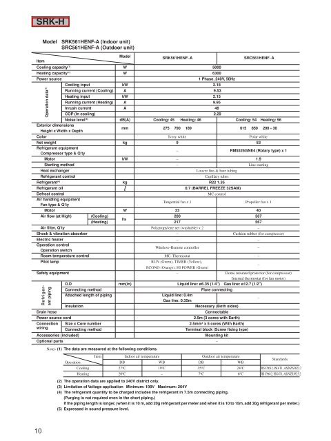
SRK-H<br />
10<br />
Model SRK561HENF-A (Indoor unit)<br />
SRC561HENF-A (Outdoor unit)<br />
Item<br />
Model<br />
SRK561HENF–A SRC561HENF–A<br />
Cooling capacity (1) W 5000<br />
Heating capacity (1) W 6300<br />
Power source 1 Phase, 240V, 50Hz<br />
Cooling input kW 2.18<br />
Running current (Cooling) A 9.53<br />
Heating input kW 2.15<br />
Running current (Heating) A 9.95<br />
Inrush current A 48<br />
COP (In cooling) 2.29<br />
Noise level (5) dB(A) Cooling: 45 Heating: 46 Cooling: 54 Heating: 56<br />
Exterior dimensions<br />
Height x Width x Depth<br />
mm 275 790 189 615 850 290 + 30<br />
Color Ivory white Polar white<br />
Net weight kg 9 53<br />
Refrigerant equipment<br />
Compressor type & Q’ty<br />
– RM5526GNE4 (Rotary type) x 1<br />
Motor kW – 1.9<br />
Starting method – Line starting<br />
Heat exchanger Louver fins & bare tubing<br />
Refrigerant control Capillary tubes<br />
Refrigerant (4) kg R22 1.35<br />
Refrigerant oil 0.7 (BARREL FREEZE 32SAM)<br />
Defrost control MC control<br />
Air handling equipment<br />
Fan type & Q’ty<br />
Tangential fan x 1 Propeller fan x 1<br />
Motor W 23 40<br />
Air flow (at High) (Cooling)<br />
(Heating)<br />
l/s<br />
200<br />
217<br />
567<br />
567<br />
Air filter, Q’ty Polypropylene net (washable) x 2 –<br />
Shock & vibration absorber – Cushion rubber (for compressor)<br />
Electric heater – –<br />
Operation control<br />
Operation switch<br />
Wireless–Remote controller –<br />
Room temperature control MC. Thermostat –<br />
Pilot lamp RUN (Green), TIMER (Yellow),<br />
ECONO (Orange), HI POWER (Green)<br />
–<br />
Safety equipment – Dome mounted protector (for compressor)<br />
Internal thermostat (for fan motor)<br />
O.D mm(in) Liquid line: ø6.35 (1/4") Gas line: ø12.7 (1/2")<br />
Connecting method Flare connecting<br />
Attached length of piping Liquid line: 0.4m<br />
Gas line: 0.35m<br />
–<br />
Insulation Necessary (Both sides)<br />
Drain hose Connectable<br />
Power source cord 2.5m (3 cores with Earth)<br />
Connection Size x Core number 2.5mm2 x 5 cores (With Earth)<br />
wiring<br />
Connecting method Terminal block (Screw fixing type)<br />
Accessories (included) Mounting kit<br />
Optional parts –<br />
Operation <strong>data</strong> (1)<br />
Refrigerant<br />
piping<br />
Notes (1) The <strong>data</strong> are measured at the following conditions.<br />
Operation<br />
Item Indoor air temperature<br />
DB WB<br />
Outdoor air temperature<br />
DB WB<br />
Standards<br />
Cooling 27ºC 19ºC 35ºC 24ºC JIS C9612, ISO-T1, AS/NZS3823.2<br />
Heating 20ºC – 7ºC 6ºC JIS C9612, ISO-T1, AS/NZS3823.2<br />
(2) The operation <strong>data</strong> are applied to 240V district only.<br />
(3) Limitation of Voltage application Minimum: 198V Maximum: 264V<br />
(4) The refrigerant quantity to be charged includes the refrigerant in 7.5m connecting piping.<br />
(Purging is not required even in the short piping.)<br />
If the piping length is longer, (when it is 10 m, add 20g refrigerant per meter and when it is 10 to 15m, add 30g refrigerant per meter.)<br />
(5) Expressed in sound pressure level.