MultilamTechnology The Multilam Principle - Multi-Contact
MultilamTechnology The Multilam Principle - Multi-Contact
MultilamTechnology The Multilam Principle - Multi-Contact

Create successful ePaper yourself
Turn your PDF publications into a flip-book with our unique Google optimized e-Paper software.
Advanced <strong>Contact</strong> Technology<br />
Kontaktlamellen<br />
<strong><strong>Multi</strong>lam</strong> <strong>Contact</strong>s<br />
<strong>Contact</strong> à lamelles<br />
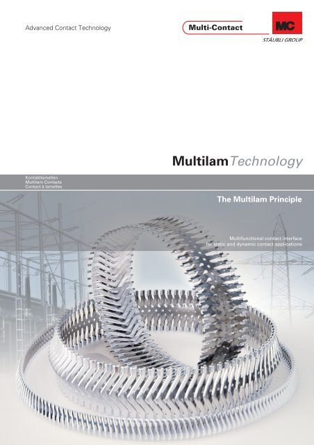
<strong><strong><strong>Multi</strong>lam</strong>Technology</strong><br />
<strong>The</strong> <strong><strong>Multi</strong>lam</strong> <strong>Principle</strong><br />
<strong>Multi</strong>functional contact interface<br />
for static and dynamic contact applications
Advanced <strong>Contact</strong> Technology<br />
Better contacts<br />
<strong>The</strong> MC <strong><strong>Multi</strong>lam</strong> brought substantial improvements in relation<br />
to conventional contact systems.<br />
Advantages<br />
<strong>The</strong> <strong><strong>Multi</strong>lam</strong> soon developed into a whole system of contact<br />
elements. Its users recognised its outstanding advantages and<br />
within a short time a wide range of new application possibilities<br />
had evolved.<br />
Basis for solutions<br />
This brochure is intended to show the principle and application<br />
of the <strong><strong>Multi</strong>lam</strong> and serves as an aid for designers and engineers<br />
in the development of high-quality and reliable contact<br />
systems.<br />
Further developments<br />
<strong>Multi</strong>-<strong>Contact</strong> uses the <strong><strong>Multi</strong>lam</strong> in all connectors in its product<br />
range, and is constantly developing new components – also in<br />
collaboration with customers.<br />
Experience<br />
<strong>Multi</strong> <strong>Contact</strong> offers total solutions because the installation and<br />
correct selection of the <strong><strong>Multi</strong>lam</strong>s require experience and<br />
know-how accumulated over many years.<br />
<strong>The</strong>re is always a solution<br />
With this extensive know-how <strong>Multi</strong>-<strong>Contact</strong> will be pleased to<br />
support you in your search for the best solution.<br />
RoHSready<br />
Directive 2002/95/EC on the restriction of the use of certain<br />
hazardous substances in electrical and electronic equipment<br />
2 www.multi-contact.com<br />
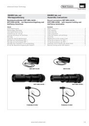
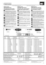
An ingenious idea<br />
<strong>The</strong> success story of <strong>Multi</strong> <strong>Contact</strong> is<br />
based on the development of specially<br />
formed hard copper strips for electrical<br />
contact, the so-called MC <strong><strong>Multi</strong>lam</strong>s.
Advanced <strong>Contact</strong> Technology<br />
<strong>Contact</strong> part A<br />
<strong><strong>Multi</strong>lam</strong> louver<br />
<strong>Contact</strong> part B <strong>The</strong> <strong><strong>Multi</strong>lam</strong> principle 4<br />
<strong>Contact</strong> part A<br />
Steel strip<br />
<strong>Contact</strong> part B<br />
Cu-louver<br />
List of terms<br />
with<br />
explanations<br />
Contents<br />
<strong>The</strong> various types of <strong><strong>Multi</strong>lam</strong>s 5<br />
Special forms of <strong><strong>Multi</strong>lam</strong> 6<br />
General contact technology 7 – 11<br />
Application range of the <strong><strong>Multi</strong>lam</strong>s, temperatures,<br />
plugging cycles, current-carrying capacity and<br />
calculation of current-carrying capacity 12 – 13<br />
Technical data and typical applications of <strong><strong>Multi</strong>lam</strong>s 14 – 19<br />
Special design features 20 – 21<br />
Glossary 22<br />
www.multi-contact.com 3
Advanced <strong>Contact</strong> Technology<br />
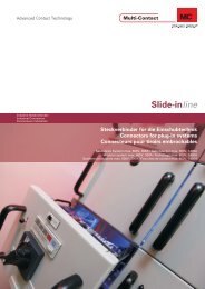
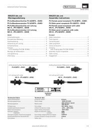
<strong>The</strong> louver contacts are produced from strips, and allow electrical<br />
contact to be made via a large number of defined, current<br />
carrying contact points.<br />
<strong>Contact</strong> part A<br />
<strong><strong>Multi</strong>lam</strong> louver<br />
<strong>Contact</strong> part B<br />
<strong>Contact</strong> arrangement with torsion spring-type <strong><strong>Multi</strong>lam</strong><br />
<strong>The</strong> <strong><strong>Multi</strong>lam</strong> <strong>Principle</strong><br />
R �R �2(R �R<br />
)<br />
k � e f<br />
Rk1 Rk2 Rk3 Rkn<br />
4 www.multi-contact.com<br />
Each louver forms an independent, spring loaded current<br />
bridge, so that the many parallel louvers substantially reduce<br />
the overall contact resistance.<br />
I<br />
<strong>Contact</strong> part B<br />
Re1 Rf1<br />
Rl Rf2 Re2<br />
<strong>The</strong> contact resistance Rk of a <strong><strong>Multi</strong>lam</strong> louver can be found by the following<br />
formula:<br />
Re 1 /Re 2 = constriction resistance<br />
R � = internal resistance of louver<br />
Rf 1 /Rf 2 = film resistance<br />
I = nominal current<br />
<strong>The</strong> contact resistance Rg of the <strong><strong>Multi</strong>lam</strong> is determined<br />
as follows: (Parallel connection of louvers)<br />
Rg<br />
1 1 1 1 1<br />
� � � �<br />
R R R R R<br />
R<br />
Rf1<br />
g k 1 k 2 k 3 kn<br />
g<br />
Rk<br />
�<br />
n<br />
Rl<br />
Re1<br />
n = number of louvers<br />
Re2<br />
Rf2<br />
<strong>Contact</strong> part A<br />
I
Advanced <strong>Contact</strong> Technology<br />
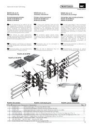
LA0 LA0-G LAIA<br />
LAIB<br />
LA-CU<br />
LAII<br />
LA-CUT/0,25/0<br />
LAI-GSR<br />
LA-CUT/0,25<br />
LAIII LAIV LAV LAVII Twisted<br />
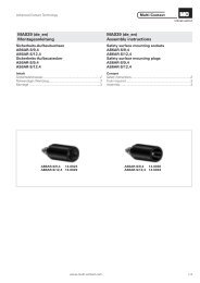
Characteristic features of the <strong><strong>Multi</strong>lam</strong>s<br />
high resistance to heat<br />
high electrical and thermal conductivity<br />
sufficiently high contact forces<br />
high number of contact cycles<br />
large operating range (LA-CUT)<br />
<strong>The</strong> various types of <strong><strong>Multi</strong>lam</strong>s<br />
MC <strong><strong>Multi</strong>lam</strong>s based on the torsion spring principle<br />
MC <strong><strong>Multi</strong>lam</strong>s based on the leaf spring principle<br />
excellent resistance to corrosion<br />
easy to process (form- and electroplate) small space requirement<br />
low cost contact elements<br />
resistance to vibration<br />
long product life<br />
www.multi-contact.com 5
Advanced <strong>Contact</strong> Technology<br />
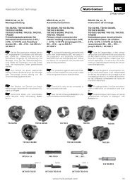
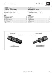
Special forms of <strong><strong>Multi</strong>lam</strong>s for special requirements<br />
LA-CUT<br />
LA-CU<br />
Functional division between spring element (steel strip) and<br />
electrical conducting element (Cu louver)<br />
Features<br />
very good electrical and thermal conductivity<br />
excellent spring characteristics<br />
low but adequate contact force keeps wear rates to an absolute<br />
minimum<br />
Functional division between spring element (steel strip) and<br />
electrical conducting element (Cu louver)<br />
Features<br />
excellent electrical conductivity<br />
high continuous current-carrying capacity<br />
high short-circuit current-carrying capacity<br />
large radial tolerance absorption<br />
6 www.multi-contact.com<br />
<strong>Contact</strong> part A<br />
Steel strip<br />
<strong>Contact</strong> part B<br />
security against excessive elongation<br />
compact width, saves space<br />
Cu-louver<br />
resistant to high tempartures (up to 180°C)<br />
Angular misalignment absorption<br />
Angular absorption +/-2° dependent on the installation mode,<br />
diameter and plug-in depth<br />
large operating range<br />
angular misalignment absorption<br />
easy to machine recess<br />
easy to install
Advanced <strong>Contact</strong> Technology<br />
<strong>The</strong> contact force<br />
General <strong>Contact</strong> Technology<br />
Connector Definitions<br />
Plug connectors are electrical connectors that must not be connected or disconnected<br />
when in use for their intended purpose (under load).<br />
Connectors: – are designed to be disconnected without load only<br />
Plug and socket devices: – are designed to be connected and disconnected under load<br />
Constant contact force<br />
over its working life<br />
Constant contact resistance<br />
over its working life<br />
Good heat dissipation<br />
during continuous operation<br />
<strong>The</strong> hardness of the contact material<br />
<strong>The</strong> service temperature<br />
Adequate contact force<br />
to break through the oxide film<br />
<strong>Contact</strong> requirements<br />
Parameters influencing the constriction resistance:<br />
the higher the contact force, the lower the constriction resistance<br />
the harder the material, the higher the constriction resistance<br />
With increasing temperature, the constriction resistance increases and then gradually<br />
breaks down when softening and melting temperatures are reached.<br />
<strong>The</strong> higher the constriction resistance increases,<br />
the higher the risk of contact welding!<br />
Low contact resistance<br />
Good thermal-shock resistance<br />
in event of short-circuit<br />
Low constriction resistance Re<br />
i.e. many and large a-spots<br />
www.multi-contact.com 7
Advanced <strong>Contact</strong> Technology<br />
Flat contact surfaces<br />
With flat contact surfaces there is no real danger of a welding effect, because the constriction resistance is spread out over many<br />
contact points. Flat contact surfaces are very susceptible to the formation of pollution films.<br />
When contact parts close, contact areas with different electrical characteristics are formed<br />
<strong>Contact</strong> parts with pollution film <strong>Contact</strong> parts closed<br />
Cu-rail under the microscope<br />
apparent contact area<br />
8 www.multi-contact.com<br />
film barrier within the supporting contact area<br />
quasi-metallic contacts<br />
effective contact area (a-spots)
Advanced <strong>Contact</strong> Technology<br />
Flat contact<br />
Current paths evenly distributed, but oxide film may not be<br />
completely broken through<br />
�<br />
R e �<br />
2�a�n<br />
Formation of contact transitions<br />
2a<br />
� = specific resistance of the contact material<br />
Re = constriction resistance<br />
n = sum of the a-spots<br />
a = radius of the effective contact areas (a-spots)<br />
Point contact<br />
Current paths restricted, oxide film is broken through but there<br />
is a high risk of welding<br />
�<br />
R e �<br />
2�a�<br />
n<br />
Assessment of contact quality<br />
<strong>The</strong> quality of a connector can be assessed by measuring the voltage drop at the rated current (DC) over the point of contact. <strong>The</strong><br />
values in the following table are based on practical experience:<br />
Class Voltage drop at rated current (DC) Assessment<br />
1 < 5mV very good<br />
2 5mV – 12mV good<br />
3 13mV – 25mV sufficient, usable<br />
4 26mV – 50mV critical unsure<br />
5 51mV – 100mV unusable<br />
6 > 100mV failed<br />
www.multi-contact.com 9<br />
2a
Advanced <strong>Contact</strong> Technology<br />
Material Electrical<br />
conductivity<br />
m<br />
2<br />
� xmm<br />
CuZn<br />
Brass<br />
CuSn6<br />
Spring bronze<br />
CuBe2<br />
Beryllium-copper<br />
CuNi18Zn20<br />
Nickel silver<br />
CuNi9Sn2<br />
Wieland L49 Ca72<br />
NiBe<br />
Nickel-Beryllium<br />
Comparison between electrical, mechanical and thermal characteristics<br />
of copper alloys and spring contact materials<br />
<strong>The</strong>rmal<br />
conductivity<br />
W<br />
m �K<br />
Vickers<br />
hardness<br />
10 www.multi-contact.com<br />
HV<br />
bending stress<br />
limit<br />
N<br />
mm 2<br />
Max. working<br />
temperature<br />
15,5 121 150 – 180 > 290 85<br />
9,5 75 160 – 220 370 125<br />
12 113<br />
max. 450<br />
hardened<br />
max. 1050<br />
hardened<br />
3,3 33 170 – 200 > 390 125<br />
6,4 48 160 – 190 > 440 125<br />
4 38<br />
440 – 510<br />
hardened<br />
max. 1600<br />
hardened<br />
°C<br />
180<br />
350<br />
Application<br />
Spring contact<br />
Plug connectors<br />
Soldering tabs<br />
Parts for switches<br />
Substrate material<br />
For relay contacts<br />
for higher<br />
temperatures<br />
Cu 57 380 – 390 60 – 120 250 – Cu-data for<br />
comparison purposes<br />
Material Thickness in µm Advantages Disadvantages<br />
Au 0,15 – 2,5<br />
Ag 5 – 10<br />
Sn 1 – 10<br />
Comparison between plating materials Au, Ag and Sn for connectors<br />
<strong>Contact</strong> requirements low contact force<br />
– good chemical stability<br />
– low contact force allowed<br />
high thermal conductivity<br />
high electrical conductivity<br />
abrasion resistant<br />
– very good electrical / thermal conductivity<br />
– DRY-CIRCUIT applications, low current and<br />
low voltage<br />
– good soldering characteristics<br />
– excellent electrical conductivity<br />
– excellent thermal conductivity<br />
– easy to form when cold<br />
– for medium and high currents<br />
– low abrasion<br />
– low cost<br />
– easy to plate<br />
– easy to tin at low temperatures<br />
– good soldering characteristics<br />
corrosion resistant<br />
suitable for plating<br />
low cost<br />
– high cost<br />
– relatively soft<br />
– diffusion barrier required<br />
– not free from pores with thin layers<br />
– subject to sulphide tarnishing<br />
– more expensive than Sn<br />
– minimum contact force<br />
– only for low no. of plugging cycles n < 100<br />
– higher plug-in and withdrawal force<br />
– higher contact force necessary 3,5N – 5N<br />
– higher abrasion<br />
– susceptible to oxidation
Advanced <strong>Contact</strong> Technology<br />
Insulation<br />
– insulating<br />
– high dielectric strength<br />
– form stable<br />
– rugged<br />
<strong>Contact</strong> element<br />
– heat resistant<br />
– elasticity<br />
Efficiency of contact<br />
– current capacity<br />
– voltage capacity<br />
– contact resistance<br />
Type of connection<br />
– soldering<br />
– clamping<br />
– AxiClamp<br />
– crimping<br />
– wrapping<br />
<strong>Contact</strong> area<br />
– plugging cycles<br />
– plating thickness<br />
– material<br />
– abrasion<br />
<strong>Contact</strong> failure<br />
– corrosion<br />
– oxide film<br />
– environment condition<br />
– misalignment<br />
Basic requirements for the design of connectors<br />
Vibration<br />
– vibration proof<br />
– shock proof<br />
plug-in force<br />
sliding force<br />
withdrawal force<br />
<strong>Contact</strong> characteristics<br />
– contact resistance<br />
– insulation resistance<br />
Standardization<br />
– assembly dimensions<br />
– contact spacing<br />
– specifications<br />
– number of poles<br />
<strong>Contact</strong> pressure<br />
– adequate<br />
– constant<br />
Frequency characteristics<br />
– capacitance<br />
– reflection factor<br />
– shield<br />
– surge impedance<br />
Price of contact<br />
– contact plating<br />
– insulation<br />
– termination type<br />
– contact elements<br />
<strong>Contact</strong> heat<br />
– thermal resistance<br />
– power dissipation<br />
– thermal conductivity<br />
<strong>Contact</strong> testing<br />
– electrical<br />
– dimensions<br />
– mechanical<br />
– thermal<br />
– climatic<br />
www.multi-contact.com 11
Advanced <strong>Contact</strong> Technology<br />
Fields of application of <strong><strong>Multi</strong>lam</strong>s<br />
<strong>The</strong>re is now a range of some 50 different <strong><strong>Multi</strong>lam</strong>s, each of<br />
which is designed for a specific application. <strong><strong>Multi</strong>lam</strong>s with a<br />
very thin � strip thickness of 0,8mm to 0,125mm are used<br />
where many plugging cycles are required. Connectors for few<br />
plugging cycles and permanent contacts for press-fitting are<br />
equipped with thicker <strong><strong>Multi</strong>lam</strong>s, e.g. 0,3mm to 0,5mm. For<br />
extreme load conditions such as in switchgear, which are characterised<br />
by a large number of plugging or sliding operations<br />
and high short-time currents, it is recommended to have the<br />
connector fitted with guide rings.<br />
Temperatures<br />
<strong>The</strong> <strong><strong>Multi</strong>lam</strong>s (Cu-Be alloy) are suitable for use at temperatures<br />
up to 180°C. In case of short circuits, temperatures up to<br />
250°C can be tolerated for a short time. <strong>The</strong> use of other alloys<br />
for <strong><strong>Multi</strong>lam</strong>s – e.g. NiBe – results in reduced current-carrying<br />
capacity and conductivity. High-temperature connectors for<br />
temperatures from 350°C – 400°C can be supplied with<br />
<strong><strong>Multi</strong>lam</strong>s made of NiBe alloy. <strong><strong>Multi</strong>lam</strong>s can also be used at<br />
extremely low temperatures. Experiments in liquid helium at<br />
4,2K have been successfully carried out.<br />
Plugging cycle<br />
<strong>The</strong> sliding forces of our connectors depend on several parameters<br />
such as the type of <strong><strong>Multi</strong>lam</strong>, plating, the base materials<br />
of the contact parts, the applied � lubricant etc. <strong>The</strong> data provided<br />
here can be regarded as typical values. <strong>The</strong> coefficients<br />
of friction typically vary around 0,35.<br />
In the technical data we state the � sliding force per louver for<br />
a mean friction coefficient of µr = 0,35. As a general rule the<br />
following equation applies:<br />
F �n���F s r k<br />
Standard high-current connectors are silver-plated to 5 – 10µm.<br />
<strong>The</strong>se platings are suitable for approximately 5,000 plugging<br />
cycles, provided they are coated with a thin film of lubricant<br />
before being used for the first time. For larger numbers of up<br />
to 30,000 plugging cycles, the <strong><strong>Multi</strong>lam</strong>s and the contact surface<br />
which slides over them can be plated with a thicker layer<br />
of silver and a thin film of lubricant applied before their first<br />
use. Plugging cycles up to 100,000 or more require special silver<br />
plating on both the <strong>Multi</strong>la’s and the contact surfaces.<br />
If more than 5,000 plugging cycles are required, MC recommends<br />
special � guide rings and “soft” (thin strip material)<br />
<strong><strong>Multi</strong>lam</strong>s. Since “soft” <strong><strong>Multi</strong>lam</strong>s have a reduced current-carrying<br />
capacity, it may be necessary to fit several <strong><strong>Multi</strong>lam</strong>s in<br />
parallel.<br />
12 www.multi-contact.com<br />
See<br />
Example<br />
See<br />
See<br />
See<br />
Example<br />
Strip thickness (Thickness of the <strong><strong>Multi</strong>lam</strong> strip)<br />
pages 14, 16, 18, 22<br />
2-pole high temperature contact for an ambient<br />
temperature of 350°C.<br />
Lubricant, page 22<br />
Sliding force per louver / medium spring deflection,<br />
pages 14, 16, 18, 22<br />
Fs = Sliding force of a contact<br />
n = Number of louvers<br />
µr = Friction coefficient<br />
Fk = <strong>Contact</strong> force per louver accord. to table<br />
pages 14, 16, 18<br />
<strong><strong>Multi</strong>lam</strong> contact with guide rings
Advanced <strong>Contact</strong> Technology<br />
Current-carrying capacity<br />
<strong>The</strong> current-carrying capacity of connections with <strong><strong>Multi</strong>lam</strong>s<br />
depends upon a number of factors which can essentially be assigned<br />
to two categories: contact resistance and environmental<br />
conditions. Below the categories are further subdivided and<br />
the relevant factors are named.<br />
1. Internal resistance of the <strong><strong>Multi</strong>lam</strong><br />
Material resistance depends on the length and the conductive<br />
cross-section<br />
Material of the louvers<br />
2. <strong>Contact</strong> resistance between the louver and<br />
the contact parts<br />
<strong>Contact</strong> force Fk<br />
Size of the contact points<br />
Coating of the <strong><strong>Multi</strong>lam</strong> and the contact parts<br />
Oxidation, pollution layers<br />
Surface roughness of the contact parts<br />
3. Resistance of the contact parts<br />
Material<br />
Cross section of the contact parts<br />
4. Environmental conditions<br />
Ambient temperature<br />
External temperature influences<br />
Environmental conditions<br />
<strong>The</strong> electrical values for <strong><strong>Multi</strong>lam</strong>s stated in the table on pages<br />
14 – 19 are based on optimum conditions. That means, for instance,<br />
that contact surfaces with a roughness of N6 must be<br />
provided with suitable and clean coatings, not oxidised or polluted.<br />
<strong>The</strong> ambient temperature is 20°C and the electrically<br />
conducting cross-sections of the contact parts must be<br />
adequate.<br />
Approximative calculation of the<br />
current-carrying capacity<br />
(Calculated with the values from tables on pages 14 – 19)<br />
Number of louvers n<br />
for round contacts:<br />
Number of louvers n<br />
for flat contacts:<br />
Total resistance Rg<br />
of a contact:<br />
n d ��<br />
�<br />
r<br />
<strong>The</strong> rated continuous current In and the short-circuit currents Ik<br />
(for 1s, 2s and 3s) and the rated peak withstand current are all<br />
calculated in the same manner with the appropriate values:<br />
R<br />
n �<br />
r<br />
�<br />
Iwhole <strong><strong>Multi</strong>lam</strong> �n�Iper louver<br />
g<br />
Rk<br />
�<br />
n<br />
Plug assembly<br />
Nominal diameter<br />
= socket diameter<br />
Socket assembly<br />
Nominal diameter<br />
= plug diameter<br />
Flat assembly<br />
n = Number of louvers<br />
d = Ø of contact<br />
� = 3,1415...<br />
r = <strong>Contact</strong> spacing<br />
(according to table pages 14,16,18)<br />
n = Number of louvers<br />
� = Length of flat contact<br />
r = <strong>Contact</strong> spacing<br />
(according to table pages 14,16,18)<br />
Rg = Overall resistance of contact assembly<br />
Rk = Average contact resistance per louver<br />
n = Number of louvers<br />
n = Number of louvers<br />
I = currents<br />
www.multi-contact.com 13
Advanced <strong>Contact</strong> Technology<br />
LA0/...<br />
LA0-G<br />
LAIA/...<br />
LAIB/...<br />
LAII/...<br />
1) <strong>The</strong> sliding force is normally determined on the end product<br />
2) see catalogue 1 Powerline<br />
Technical data and typical applications of MC <strong><strong>Multi</strong>lam</strong>s<br />
<strong><strong>Multi</strong>lam</strong> type Typical Sizes Applications Dimensions Mechanical data<br />
LA0/0,15<br />
LA0/0,20<br />
LA0/0,25<br />
LA0/0,30<br />
14 www.multi-contact.com<br />
Width of <strong><strong>Multi</strong>lam</strong><br />
mm b<br />
mm<br />
> Ø 25<br />
> Ø 25<br />
> Ø 25<br />
> Ø 25<br />
LA0-G/0,25 > Ø 25<br />
LAIA/0,08<br />
LAIA/0,10<br />
LAIA/0,125<br />
LAIA/0,15<br />
LAIA/0,20<br />
LAIA/0,25<br />
LAIA/0,30<br />
LAIA/0,40<br />
LAIA/0,50<br />
LAIB/0,08<br />
LAIB/0,10<br />
LAIB/0,125<br />
LAIB/0,15<br />
LAIB/0,20<br />
LAIB/0,25<br />
LAIB/0,30<br />
LAII/0,15<br />
LAII/0,20<br />
Ø 8 – Ø 20<br />
Ø 8 – Ø 20<br />
Ø 8 – Ø 20<br />
Ø 8 – Ø 20<br />
Ø 8 – Ø 20<br />
Ø 8 – Ø 20<br />
Ø 15 – Ø 20<br />
Ø 20 – Ø 70<br />
Ø 20 – Ø 70<br />
Ø 25 – Ø 70<br />
Ø 25 – Ø 70<br />
Ø 25 – Ø 70<br />
Ø 25 – Ø 70<br />
Ø 25 – Ø 70<br />
Ø 25 – Ø 70<br />
Ø 25 – Ø 70<br />
Ø 3,5 – Ø 20<br />
Ø 3,5 – Ø 20<br />
Switches,<br />
disconnectors<br />
earth connectors<br />
sliding and rotary<br />
connectors<br />
Switches,<br />
disconnectors<br />
earth connectors<br />
sliding contacts<br />
Round contacts<br />
as in B8N to<br />
B20N 2) ,<br />
Flat contacts,<br />
as in fork plugs<br />
Round contacts<br />
as in B25N to<br />
B40N 2) ,<br />
switches,<br />
disconnectors,<br />
earth connectors,<br />
sliding and rotary<br />
contacts<br />
Transformers<br />
and fork plugs<br />
26<br />
26<br />
26<br />
26<br />
Thickness of<br />
<strong><strong>Multi</strong>lam</strong> strip<br />
s<br />
mm<br />
0,15<br />
0,2<br />
0,25<br />
0,3<br />
<strong>Contact</strong> spacing<br />
r<br />
mm<br />
5<br />
5<br />
5<br />
5<br />
<strong>Contact</strong> force per<br />
louver with medium<br />
spring deflection<br />
Fk<br />
N<br />
3<br />
8,5<br />
15<br />
17<br />
Sliding force per<br />
louver with medium<br />
spring defl. µr =0,35<br />
Fs<br />
N<br />
1,05<br />
3<br />
5,25<br />
6<br />
25 0,25 2,5 9 3,15<br />
17,5<br />
17,5<br />
17,5<br />
17,5<br />
17,5<br />
17,5<br />
17,5<br />
17,5<br />
17,5<br />
17,6<br />
17,6<br />
17,6<br />
17,6<br />
17,6<br />
17,6<br />
17,6<br />
14<br />
14<br />
0,08<br />
0,1<br />
0,125<br />
0,15<br />
0,2<br />
0,25<br />
0,3<br />
0,4<br />
0,5<br />
0,08<br />
0,1<br />
0,125<br />
0,15<br />
0,2<br />
0,25<br />
0,3<br />
0,15<br />
0,2<br />
2,5<br />
2,5<br />
2,5<br />
2,5<br />
2,5<br />
2,5<br />
2,5<br />
2,5<br />
2,5<br />
2,5<br />
2,5<br />
2,5<br />
2,5<br />
2,5<br />
2,5<br />
2,5<br />
1,5<br />
1,5<br />
1<br />
3<br />
4<br />
7<br />
15<br />
20<br />
32,5<br />
68<br />
105<br />
1<br />
3<br />
4<br />
7<br />
15<br />
20<br />
32,5<br />
10<br />
16<br />
0,35<br />
1,05<br />
1,4<br />
2,5<br />
5,25<br />
7<br />
11,4<br />
23,8<br />
37<br />
0,35<br />
1,05<br />
1,4<br />
2,5<br />
5,25<br />
7<br />
11,4<br />
3,5<br />
5,6
Advanced <strong>Contact</strong> Technology<br />
Rated current (A)<br />
per louver<br />
l<br />
n<br />
A<br />
<strong>Contact</strong> resistance (m�)<br />
per louver<br />
R<br />
k<br />
m�<br />
Electrical data 1)<br />
Short circuit current (kA)<br />
per louver at<br />
lk11s kA<br />
( ) lk2( 2s)<br />
lk3( 3s)<br />
kA kA<br />
Rated peak withstand current (kA)<br />
per louver<br />
0 7 14 21 28 35 42 49 56 63 0 0,1 0,2 0,3 0,4 0,5 0,6 0,7 0,8 0,9 1,0 0 0,2 0,4 0,6 0,8 1,0 1,2 1,4 1,6 1,8 0 0,7 1,4 2,1 2,8 3,5 4,2 4,9 5,6 6,3<br />
1) valid for <strong><strong>Multi</strong>lam</strong>s made from hard copper, silver-plated (mating part Cu, silver-plated)<br />
www.multi-contact.com 15<br />
l<br />
p<br />
kA
Advanced <strong>Contact</strong> Technology<br />
LA-CU<br />
LA-CUT<br />
Technical data and typical applications of MC <strong><strong>Multi</strong>lam</strong>s<br />
<strong><strong>Multi</strong>lam</strong> type Typical Sizes Applications Dimensions Mechanical data <strong>The</strong>rmal data<br />
LA-CU/0,15-0,5 Ø 12 – Ø 400<br />
LA-CUT/0,25 > Ø 50<br />
LA-CUT/0,25/0 > Ø 50<br />
1) <strong>The</strong> sliding force is normally determined on the end product<br />
16 www.multi-contact.com<br />
Width of <strong><strong>Multi</strong>lam</strong><br />
mm b<br />
mm<br />
Switches<br />
disconnectors<br />
earth,<br />
connectors<br />
sliding and rotary<br />
contacts<br />
Switches<br />
disconnectors<br />
earth,<br />
connectors<br />
sliding and rotary<br />
contacts<br />
Switches<br />
disconnectors<br />
earth,<br />
connectors<br />
sliding and rotary<br />
contacts<br />
Thickness of<br />
<strong><strong>Multi</strong>lam</strong> strip<br />
s<br />
mm<br />
<strong>Contact</strong> spacing<br />
r<br />
mm<br />
<strong>Contact</strong> force per<br />
louver with medium<br />
spring deflection<br />
Fk<br />
N<br />
Sliding force per<br />
louver with medium<br />
spring defl. µr =0,35<br />
Fs<br />
N<br />
Continuous using<br />
temperature<br />
Short time<br />
temperature<br />
<strong>The</strong>rmal resistance<br />
per louver<br />
°C °C K/W<br />
12 0,15 (Cu 0,5) 3,5 7 2,5 180 250 25<br />
26 0,25 (Cu 1) 4 10 1 – 2 1) 150 250 25 – 30<br />
30 0,25 (Cu 1) 4 10 1 – 2 1) 150 250 25 – 30
Advanced <strong>Contact</strong> Technology<br />
Rated current (A)<br />
per louver<br />
l<br />
n1 l n 2<br />
A<br />
A<br />
<strong>Contact</strong> resistance (m�)<br />
per louver<br />
R<br />
k<br />
m�<br />
Electrical data 1)<br />
Short circuit current (kA)<br />
per louver at<br />
l ( s)<br />
l ( s)<br />
l ( s)<br />
k1 1<br />
kA<br />
k 2 2<br />
kA<br />
k 3 3<br />
kA<br />
Rated peak withstand current (kA)<br />
per louver<br />
0 10 20 30 40 50 60 70 80 90 0 0,1 0,2 0,3 0,4 0,5 0,6 0,7 0,8 0,9 1,0 0 0,2 0,4 0,6 0,8 1,0 1,2 1,4 1,6 0 0,6 1,2 1,8 2,4 3,0 3,6 4,2 4,8 5,4<br />
1) Valid for MC <strong><strong>Multi</strong>lam</strong> <strong>Contact</strong>s, silver-plated (mating part Cu, silver-plated)<br />
www.multi-contact.com 17<br />
l<br />
p<br />
kA
Advanced <strong>Contact</strong> Technology<br />
LAIII<br />
LAIV<br />
LAV<br />
LAVII<br />
Technical data and typical applications of MC <strong><strong>Multi</strong>lam</strong>s<br />
<strong><strong>Multi</strong>lam</strong> type Typical Sizes Applications Dimensions Mechanical data<br />
LAIII/0,125<br />
LASIII/0,15<br />
LAIII/0,20<br />
LAIII/0,30<br />
LAIV/0,10<br />
LAIV/0,125<br />
LAIV/0,15<br />
LAV/0,10<br />
LAV/0,125<br />
LAV/0,15<br />
18 www.multi-contact.com<br />
Width of <strong><strong>Multi</strong>lam</strong><br />
mm b<br />
mm<br />
Ø 2 – Ø 20<br />
Ø 2 – Ø 20<br />
Ø 2 – Ø 20<br />
Ø 2 – Ø 20<br />
Ø 0,5 – Ø 4<br />
Ø 0,5 – Ø 4<br />
Ø 0,5 – Ø 4<br />
Ø 0,5 – Ø 4<br />
Ø 0,5 – Ø 4<br />
Ø 0,5 – Ø 4<br />
Test cables,<br />
probes<br />
Test cables,<br />
probes,<br />
miniature<br />
sockets<br />
Miniature<br />
sockets<br />
12<br />
12<br />
12<br />
12<br />
8<br />
8<br />
8<br />
5<br />
5<br />
5<br />
Thickness of<br />
<strong><strong>Multi</strong>lam</strong> strip<br />
s<br />
mm<br />
0,125<br />
0,150<br />
0,200<br />
0,300<br />
0,100<br />
0,125<br />
0,150<br />
0,100<br />
0,125<br />
0,150<br />
<strong>Contact</strong> spacing<br />
r<br />
mm<br />
0,8 – 1,0<br />
0,8 – 1,0<br />
0,8 – 1,0<br />
0,8 – 1,0<br />
0,6 – 0,8<br />
0,6 – 0,8<br />
0,6 – 0,8<br />
0,6 – 0,8<br />
0,6 – 0,8<br />
0,6 – 0,8<br />
<strong>Contact</strong> force per<br />
louver with medium<br />
spring deflection<br />
LAVII/0,125 Ø 0,8 – Ø 2,36 Miniature<br />
sockets 3 0,125 0,6 – 0,8 – –<br />
1) <strong>The</strong> sliding force will be determined by the end product<br />
2) No indication of guide values possible, these values depend on the final use<br />
Fk<br />
N<br />
3,5<br />
7<br />
2)<br />
–<br />
–<br />
–<br />
10<br />
–<br />
–<br />
3<br />
Sliding force per<br />
louver with medium<br />
spring defl. µr =0,35<br />
Fs<br />
N<br />
1,25<br />
2,5<br />
2)<br />
–<br />
–<br />
–<br />
3,5<br />
–<br />
–<br />
1,05
Advanced <strong>Contact</strong> Technology<br />
Rated current (A)<br />
per louver<br />
l<br />
n1<br />
A<br />
<strong>Contact</strong> resistance (m�)<br />
per louver<br />
R<br />
k<br />
m�<br />
Electrical data 1)<br />
Short circuit current (kA)<br />
per louver at<br />
lk11s kA<br />
( ) lk2( 2s)<br />
lk3( 3s)<br />
kA kA<br />
Rated peak withstand current (kA)<br />
per louver<br />
0 1,5 3,0 4,5 6,0 7,5 9,0 10,5 12,0 13,5 0 0,1 0,2 0,3 0,4 0,5 0,6 0,7 0,8 0,9 1,0 0 0,04 0,08 0,12 0,16 0,20 0,24 0,28 0,32 0,36 0 0,1 0,2 0,3 0,4 0,5 0,6 0,7 0,8 0,9<br />
1) Valid for <strong><strong>Multi</strong>lam</strong>s made from hard copper, gold-plated<br />
2) No indication of guide values possible, these values depend on the final use<br />
www.multi-contact.com 19<br />
l<br />
p<br />
kA
Advanced <strong>Contact</strong> Technology<br />
Cylindrical contacts<br />
<strong>The</strong> <strong><strong>Multi</strong>lam</strong>s are fitted on cylindrical<br />
contact rings. Either in a socket (female),<br />
the mating part being a rigid pin,<br />
or on a pin (male) and the mating part a<br />
rigid socket. Also for dynamic applications<br />
(axial movement or rotatable).<br />
Spherical contacts<br />
Accommodate angular misalignments<br />
and axial movements (sliding).<br />
Special design features<br />
With MC <strong><strong>Multi</strong>lam</strong> technology, users have available an extremely<br />
flexible and individually adaptable contact interface.<br />
20 www.multi-contact.com<br />
Flat contacts<br />
are suitable for connecting busbars, either<br />
as a connector or a clamping unit.<br />
This allows connection and disconnection<br />
with large busbars.<br />
Fork contacts<br />
are suitable for connecting busbars to<br />
the plug-in module system. Connections<br />
to parallel busbars can easily be made<br />
with “floating” fork contacts.
Advanced <strong>Contact</strong> Technology<br />
MC <strong><strong>Multi</strong>lam</strong>s<br />
Countless applications and a basis for new developments<br />
<strong>The</strong> first step to a solution for<br />
your own contact<br />
is a simple form to be filled in online with your contact requirements<br />
You will find this form under:<br />
www.multi-contact.com > Downloads > Online Forms ><br />
Checklist / Inquiry Form<br />
Send the generated pdf-form, together with possible additions<br />
or additional requirements by mail to:<br />
basel@multi-contact.com<br />
<strong>Multi</strong>-<strong>Contact</strong><br />
www.multi-contact.com 21
Advanced <strong>Contact</strong> Technology<br />
Strip thickness s<br />
Thickness of the <strong><strong>Multi</strong>lam</strong> strip without plating.<br />
Leaf spring <strong><strong>Multi</strong>lam</strong><br />
Individual louvers have a spring action as a result of their<br />
curved shape. Leaf spring <strong><strong>Multi</strong>lam</strong> bands are usually gold or<br />
nickel plated.<br />
Torsion spring <strong><strong>Multi</strong>lam</strong><br />
MC <strong><strong>Multi</strong>lam</strong> type with individual louvers which deflect under<br />
torsion. <strong>The</strong>y are made from copper alloy and are usually silver<br />
plated.<br />
Definition In1, In2<br />
In1 = Nominal current under normal environmental conditions<br />
and good contact quality according to table, page 9. In1 is the<br />
basis for MC design.<br />
In2 = Nominal current under optimal environmental conditions<br />
and sufficient contact quality according to table, page 9.<br />
Internal resistance of the louver<br />
results from the specific resistance of the louver material, the<br />
distance the current must travel through the louver and the active<br />
cross-section.<br />
Standards<br />
IEC 61984 (VDE 0627):<br />
Safety requirements and tests for plug connectors.<br />
IEC 61010-031 (VDE 0411-031):<br />
Safety regulations and hand-held accessories for test and measurement.<br />
IEC 62271-1 (VDE 0671-1):<br />
High voltage switchgear and switch devices – general definitions.<br />
<strong>Contact</strong> force Fk<br />
is defined as the spring force of a louver at medium deflection.<br />
<strong>Contact</strong> resistance<br />
is the resistance of the point of contact between the <strong><strong>Multi</strong>lam</strong><br />
and the contact parts.<br />
<strong><strong>Multi</strong>lam</strong> recess<br />
Groove milled into the contact part for the “floating” mounting<br />
of a <strong><strong>Multi</strong>lam</strong> louver.<br />
RoHS – 2002/95/EC<br />
European Directive 2002/95/EC (“RoHS” for short) restricts the<br />
use of certain hazardous substances in household equipment.<br />
<strong><strong>Multi</strong>lam</strong> strips are component parts, and as such are not directly<br />
affected by this directive. <strong>The</strong>y also contain none of the<br />
substances which are scheduled under the directive and can<br />
therefore be safely incorporated in devices to which the<br />
directive applies.<br />
Glossary<br />
22 www.multi-contact.com<br />
<strong><strong>Multi</strong>lam</strong> louver<br />
Individual contact element of a <strong><strong>Multi</strong>lam</strong> strip; there are either<br />
� leaf spring louvers or � torsion spring louvers.<br />
<strong>Contact</strong> spacing r<br />
is the distance between the centres of two � <strong><strong>Multi</strong>lam</strong> louvers.<br />
Sliding force FS<br />
is the purely frictional force of the deflected <strong><strong>Multi</strong>lam</strong>.<br />
<strong>The</strong> stated figures are average values obtained with a thin lubricant<br />
film and after 20 – 30 mating cycles. <strong>The</strong> values are<br />
higher in new connectors. <strong>The</strong> sliding force is determined in<br />
the end product, since its value is not determined solely by the<br />
<strong><strong>Multi</strong>lam</strong>.<br />
Plug-in force FSt<br />
is the maximum force needed in order to deflect the <strong><strong>Multi</strong>lam</strong><br />
when mating the connector. It is made up of the spring force<br />
and the frictional force.<br />
<strong>The</strong> plug-in force is determined in the end product, since its<br />
value is not determined solely by the <strong><strong>Multi</strong>lam</strong>.<br />
It should be noted that the plug-in force is always greater than<br />
the sliding force. <strong>The</strong> plug-in force is usually not indicated.<br />
Force<br />
Difference between plug-in force and sliding force<br />
F St<br />
Mating way<br />
Lubricants<br />
MC recommends the following lubricants:<br />
Grease (general electrical contacts):<br />
METALON HT-1,5-50ML (73.1052)<br />
KONTASYNTH BA100 SPRAY (73.1051)*<br />
Sliding grease:<br />
in SF6-Gas: Barrierta I EL-102*<br />
Press-fitting and sealing grease:<br />
Barrierta I S-402 or Barrierta I MI-202*<br />
* from Klüber Lubrication, Munich.<br />
FS
Advanced <strong>Contact</strong> Technology<br />
www.multi-contact.com 23
Advanced <strong>Contact</strong> Technology<br />
Headquarters:<br />
<strong>Multi</strong>-<strong>Contact</strong> AG<br />
Stockbrunnenrain 8<br />
CH – 4123 Allschwil<br />
Tel. +41/61/306 55 55<br />
Fax +41/61/306 55 56<br />
mail basel@multi-contact.com<br />
www.multi-contact.com<br />
<strong>Multi</strong>-<strong>Contact</strong> Deutschland GmbH<br />
Hegenheimer Strasse 19<br />
Postfach 1606<br />
DE – 79551 Weil am Rhein<br />
Tel. +49/76 21/6 67 - 0<br />
Fax +49/76 21/6 67 - 100<br />
mail weil@multi-contact.com<br />
<strong>Multi</strong>-<strong>Contact</strong><br />
Handelsges.m.b.H. Austria<br />
Hauptplatz 8<br />
AT – 3452 Heiligeneich<br />
Tel. +43/2275/56 56<br />
Fax +43/2275/56 56 4<br />
mail austria@multi-contact.com<br />
<strong>Multi</strong>-<strong>Contact</strong> Benelux<br />
c/o Stäubli Benelux N.V.<br />
Meensesteenweg 407<br />
BE – 8501 Bissegem<br />
Tel. +32/56 36 41 00<br />
Fax +32/56 36 41 10<br />
mail benelux@multi-contact.com<br />
<strong>Multi</strong>-<strong>Contact</strong> Czech<br />
c/o Stäubli Systems, s.r.o.<br />
Hradecká 536<br />
CZ – 53009 Pardubice<br />
Tel. +420/466/616 126<br />
Fax +420/466/616 127<br />
mail connectors.cz@staubli.com<br />
<strong>Multi</strong>-<strong>Contact</strong> Española<br />
c/o Stäubli Española S.A.<br />
C/Marià Aguiló, 4 – 1°<br />
ES – 08205 Sabadell<br />
Tel. +34/93/720 65 50<br />
Fax +34/93/712 42 56<br />
mail spain@multi-contact.com<br />
Ihre <strong>Multi</strong>-<strong>Contact</strong> Vertretung:<br />
Your <strong>Multi</strong>-<strong>Contact</strong> representative:<br />
Votre représentant <strong>Multi</strong>-<strong>Contact</strong>:<br />
<strong>Multi</strong>-<strong>Contact</strong> Essen GmbH<br />
Westendstrasse 10<br />
Postfach 102 527<br />
DE – 45025 Essen<br />
Tel. +49/2 01/8 31 05 - 0<br />
Fax +49/2 01/8 31 05 - 99<br />
mail essen@multi-contact.com<br />
<strong>Multi</strong>-<strong>Contact</strong> (UK) Ltd.<br />
3 Presley Way<br />
Crownhill, Milton Keynes<br />
GB – Buckinghamshire MK8 0ES<br />
Tel. +44/1908 26 55 44<br />
Fax +44/1908 26 20 80<br />
mail uk@multi-contact.com<br />
<strong>Multi</strong>-<strong>Contact</strong> Italia<br />
c/o Stäubli Italia S.p.A.<br />
Via Rivera, 55<br />
IT – 20841 Carate Brianza (MB)<br />
Tel. +39/0362/94 45 01<br />
Fax +39/0362/94 45 80<br />
mail italy@multi-contact.com<br />
<strong>Multi</strong>-<strong>Contact</strong> Portugal<br />
c/o Stäubli Portugal<br />
Representações Lda<br />
Via Central de Milheirós, 171-A<br />
PT – 4475-330 Milheirós / Maia<br />
Tel. +351/229 783 956<br />
Fax +351/229 783 959<br />
mail portugal@multi-contact.com<br />
<strong>Multi</strong>-<strong>Contact</strong> Türkiye<br />
c/o Stäubli Sanayi Makine ve<br />
Aksesuarlari Ticaret Ltd. ¸Sti.<br />
Atatürk Mahallesi, Marmara<br />
Sanayi Sitesi, B Blok No: 28 Ikitelli<br />
TR – 34306 Istanbul<br />
Tel. +90/212/472 13 00<br />
Fax +90/212/472 12 30<br />
mail turkey@multi-contact.com<br />
<strong>Multi</strong>-<strong>Contact</strong> France SAS<br />
4 rue de l’Industrie<br />
BP 37<br />
FR – 68221 Hésingue Cedex<br />
Tel. +33/3/89 67 65 70<br />
Fax +33/3/89 69 27 96<br />
mail france@multi-contact.com<br />
<strong>Multi</strong>-<strong>Contact</strong> Russia<br />
OOO STAUBLI RUS<br />
ul.Startovaya 8a<br />
RU – 196210 Saint Petersburg<br />
Tel. +7/812/334 46 30<br />
Fax +7/812/334 46 36<br />
mail russia@multi-contact.com<br />
www.multi-contact-russia.com<br />
<strong>Multi</strong>-<strong>Contact</strong> Brazil<br />
c/o Stäubli Comércio, Importação,<br />
Exportação e Representações Ltda.<br />
Rua Henri Dunant, 137 - Conj. D<br />
BR – 04709-110 São Paulo<br />
Tel. +55/11/2348 7400<br />
Fax +55/11/5181 8334<br />
mail brazil@multi-contact.com<br />
<strong>Multi</strong>-<strong>Contact</strong> China<br />
c/o Stäubli Mechatronic Co. Ltd.<br />
Hangzhou Economic and<br />
Technological Development Zone<br />
No. 5, 4 th Street<br />
CN – 310018 Hangzhou<br />
Tel. +86/571/869 121 61<br />
Fax +86/571/869 125 22<br />
mail hangzhou@staubli.com<br />
<strong>Multi</strong>-<strong>Contact</strong> Hongkong<br />
c/o Stäubli (H.K.) Ltd.<br />
Unit 87, 12/F, HITEC<br />
No. 1 Trademart Drive<br />
Kowloon Bay<br />
HK – Hong Kong<br />
Tel. +852/2366 0660<br />
Fax +852/2311 4677<br />
mail connectors.hk@staubli.com<br />
<strong>Multi</strong>-<strong>Contact</strong> USA<br />
100 Market Street<br />
US – Windsor, CA 95492<br />
Tel. +1/707/838 - 0530<br />
Fax +1/707/838 - 2474<br />
mail usa@multi-contact.com<br />
www.multi-contact-usa.com<br />
<strong>Multi</strong>-<strong>Contact</strong> Taiwan<br />
c/o Stäubli (H.K.) Ltd.<br />
Taiwan Branch<br />
6/F-3, No. 21, Lane 583<br />
Ruiguang Road, Neihu Dist.<br />
TW – Taipei City 11466<br />
Tel. +886/2/8797 7795<br />
Fax +886/2/8797 8895<br />
mail connectors.tw@staubli.com<br />
<strong>Multi</strong>-<strong>Contact</strong> Korea<br />
c/o Stäubli Korea Co., Ltd.<br />
2F, DCCI, 107-2,<br />
Shincheon-dong, Dong-gu,<br />
ROK – 701-702 Daegu<br />
Tel. +82/53/753/0075<br />
Fax +82/53/753/0072<br />
mail korea@multi-contact.com<br />
<strong>Multi</strong>-<strong>Contact</strong><br />
(South East Asia) Pte. Ltd.<br />
215 Henderson Road #01-02<br />
Henderson Industrial Park<br />
SG – Singapore 159554<br />
Tel. +65/626 609 00<br />
Fax +65/626 610 66<br />
mail singapore@multi-contact.com<br />
<strong>Multi</strong>-<strong>Contact</strong> (Thailand) Co., Ltd.<br />
160/865-866 Silom Road<br />
ITF-Silom Palace 33 rd Floor<br />
Suriyawong, Bangrak<br />
TH – Bangkok 10500<br />
Tel. +66/2/266 78 79; 268 08 04<br />
Fax +66/2/267 76 80<br />
mail thailand@multi-contact.com<br />
Sie finden Ihren Ansprechpartner unter:<br />
You will find your local partner at:<br />
Trouvez vos contacts sous:<br />
www.multi-contact.com<br />
© <strong>Multi</strong>-<strong>Contact</strong> AG, Switzerland, 12.2009 (1) 11.2011/1000/WD – <strong><strong><strong>Multi</strong>lam</strong>Technology</strong> – Global Communications – Änderungen vorbehalten / Subject to alterations / Sous réserve de modifications.