Electrical Wiring Diagrams
Electrical Wiring Diagrams
Electrical Wiring Diagrams

Create successful ePaper yourself
Turn your PDF publications into a flip-book with our unique Google optimized e-Paper software.
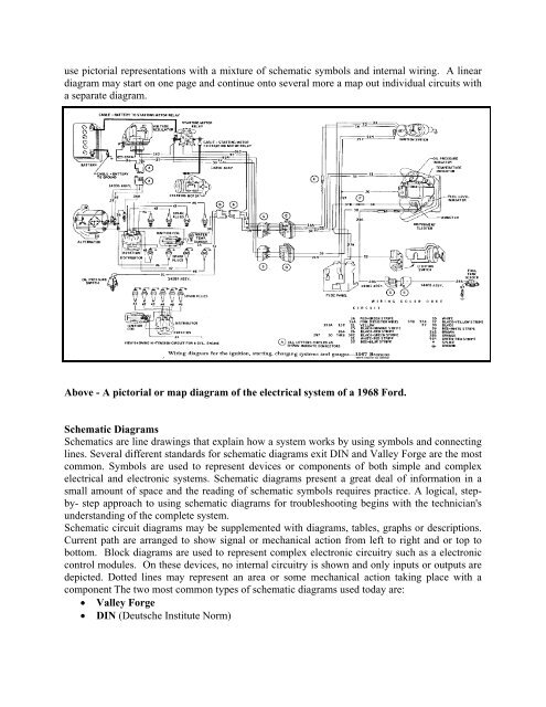
use pictorial representations with a mixture of schematic symbols and internal wiring. A linear<br />
diagram may start on one page and continue onto several more a map out individual circuits with<br />
a separate diagram.<br />
Above - A pictorial or map diagram of the electrical system of a 1968 Ford.<br />
Schematic <strong>Diagrams</strong><br />
Schematics are line drawings that explain how a system works by using symbols and connecting<br />
lines. Several different standards for schematic diagrams exit DIN and Valley Forge are the most<br />
common. Symbols are used to represent devices or components of both simple and complex<br />
electrical and electronic systems. Schematic diagrams present a great deal of information in a<br />
small amount of space and the reading of schematic symbols requires practice. A logical, stepby-<br />
step approach to using schematic diagrams for troubleshooting begins with the technician's<br />
understanding of the complete system.<br />
Schematic circuit diagrams may be supplemented with diagrams, tables, graphs or descriptions.<br />
Current path are arranged to show signal or mechanical action from left to right and or top to<br />
bottom. Block diagrams are used to represent complex electronic circuitry such as a electronic<br />
control modules. On these devices, no internal circuitry is shown and only inputs or outputs are<br />
depicted. Dotted lines may represent an area or some mechanical action taking place with a<br />
component The two most common types of schematic diagrams used today are:<br />
� Valley Forge<br />
� DIN (Deutsche Institute Norm)