Electrical Wiring Diagrams
Electrical Wiring Diagrams
Electrical Wiring Diagrams

Create successful ePaper yourself
Turn your PDF publications into a flip-book with our unique Google optimized e-Paper software.
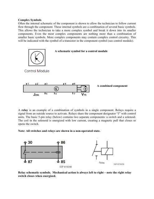
Complex Symbols<br />
Often the internal schematic of the component is shown to allow the technician to follow current<br />
flow through the component. These internal symbols are a combination of several basic symbols.<br />
This allows the technician to take a more complex symbol and break it down into its smaller<br />
components. Even the most complex components are nothing more than a combination of<br />
smaller basic symbols. More complex components may contain complex control circuitry. This<br />
will be indicated with the symbol of a transistor in the component symbol (see control module).<br />
A schematic symbol for a control module<br />
A combined component<br />
A relay is an example of a combination of symbols in a single component. Relays require a<br />
signal from an outside source to activate. Relays share the component designator “J” with control<br />
units. The basic 5-pin relay (below) contains two separate components: a switch and a solenoid.<br />
The coil in the solenoid is energized with low current, creating a magnetic pull that closes or<br />
opens the switch.<br />
Note: All switches and relays are shown in a non-operated state.<br />
Relay schematic symbols. Mechanical action is always left to right – note the right relay<br />
switch closes when energized.