stress transformation and mohr's circle - Foundation Coalition
stress transformation and mohr's circle - Foundation Coalition
stress transformation and mohr's circle - Foundation Coalition

You also want an ePaper? Increase the reach of your titles
YUMPU automatically turns print PDFs into web optimized ePapers that Google loves.
Chapter 5<br />
STRESS TRANSFORMATION<br />
AND MOHR’S CIRCLE<br />
5.1 Stress Transformations <strong>and</strong> Mohr’s Circle<br />
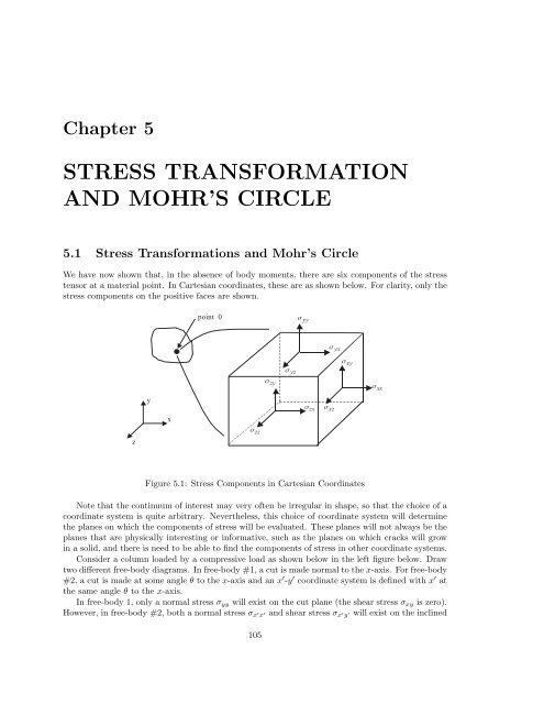
We have now shown that, in the absence of body moments, there are six components of the <strong>stress</strong><br />
tensor at a material point. In Cartesian coordinates, these are as shown below. For clarity, only the<br />
<strong>stress</strong> components on the positive faces are shown.<br />
z<br />
y<br />
x<br />
point 0<br />
σ zz<br />
σ zy<br />
σ yz<br />
σ yy<br />
σ zx<br />
σ yx<br />
σ xz<br />
σ xy<br />
Figure 5.1: Stress Components in Cartesian Coordinates<br />
Note that the continuum of interest may very often be irregular in shape, so that the choice of a<br />
coordinate system is quite arbitrary. Nevertheless, this choice of coordinate system will determine<br />
the planes on which the components of <strong>stress</strong> will be evaluated. These planes will not always be the<br />
planes that are physically interesting or informative, such as the planes on which cracks will grow<br />
in a solid, <strong>and</strong> there is need to be able to find the components of <strong>stress</strong> in other coordinate systems.<br />
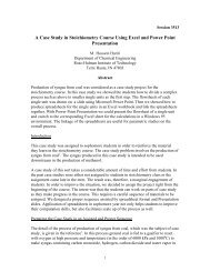
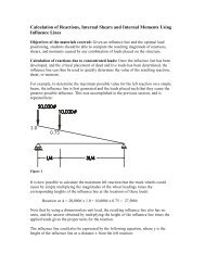
Consider a column loaded by a compressive load as shown below in the left figure below. Draw<br />
two different free-body diagrams. In free-body #1, a cut is made normal to the x-axis. For free-body<br />
#2, a cut is made at some angle θ to the x-axis <strong>and</strong> an x ′ -y ′ coordinate system is defined with x ′ at<br />
the same angle θ to the x-axis.<br />
In free-body 1, only a normal <strong>stress</strong> σyy will exist on the cut plane (the shear <strong>stress</strong> σxy is zero).<br />
However, in free-body #2, both a normal <strong>stress</strong> σx ′ x ′ <strong>and</strong> shear <strong>stress</strong> σx ′ y ′ will exist on the inclined<br />
105<br />
σ xx
106 CHAPTER 5. STRESS TRANSFORMATION AND MOHR’S CIRCLE<br />
p p<br />
y<br />
x<br />
σ x ′ y ′<br />
σ x ′ x ′<br />
column with<br />
compressive load free-body #1 free-body #2<br />
σyy<br />
Figure 5.2: Column Loaded in Compression<br />
plane (the traction vector on the inclined surface must have two components so that the resultant<br />
force equilibrates the applied load). Consequently, it is important to be able to define the <strong>stress</strong> on<br />
any plane with any orientation relative to the x-axis. In this case, no shear <strong>stress</strong> exists in the x-y<br />
coordinate system, but does exist in the x ′ -y ′ coordinate system. In free-body #2, σx ′ x ′ <strong>and</strong> σx ′ y ′<br />
must satisfy conservation of linear momentum such that the sum of the horizontal components of<br />
the forces due to the <strong>stress</strong>es are zero, while the sum of the vertical components must equal the<br />
vertical force due to the applied traction on the column.<br />
Thus, it is desirable to develop a method for determining the <strong>stress</strong>es on arbitrary planes at any<br />
point once σxx, σyy, σzz, σyz, σxz, <strong>and</strong> σxy have been determined. The process of finding these<br />
<strong>stress</strong>es in a coordinate system like x ′ -y ′ , which is rotated by some angle θ relative to the x-axis, is<br />
called <strong>stress</strong> <strong>transformation</strong>.<br />
In this text, we will consider only states of <strong>stress</strong> in which shear <strong>stress</strong>es are non-zero in at most<br />
one plane. This state of <strong>stress</strong> is termed generalized plane <strong>stress</strong>. An example of generalized<br />
plane <strong>stress</strong> in the x-y plane is shown below. Note that no shear <strong>stress</strong>es exist in the y-z or x-z<br />
planes for this example.<br />
z<br />
y<br />
σ xx<br />
x<br />
σ zz<br />
σ xy<br />
σ yx<br />
σ yy<br />
σ yy<br />
σ yx<br />
σ xy<br />
p<br />
σ zz<br />
σ xx<br />
Figure 5.3: Generalized Plane Stress in x-y Plane<br />
Principal <strong>stress</strong> is defined as the normal <strong>stress</strong> that exists on a plane (at some angle θ) where<br />
y ′<br />
θ<br />
x ′
5.1. STRESS TRANSFORMATIONS AND MOHR’S CIRCLE 107<br />
all shear <strong>stress</strong>es are equal to zero. In Figure 5.3 above, σzz is a principal <strong>stress</strong> since no shear<br />
<strong>stress</strong>es are shown on the z face (the face with unit outward normal k). Since the coordinate system<br />
is arbitrary, note that if a state of generalized plane <strong>stress</strong> exists at a point, the coordinate system<br />
can always be rotated such that the x ′ -y ′ <strong>stress</strong> state is as shown below in Figure 5.4<br />
Consider a solid body such as that shown below. Suppose that we start with the state of <strong>stress</strong><br />
defined in x-y coordinates.<br />
z<br />
y<br />
x<br />
F 1<br />
point 0<br />
F 2<br />
p<br />
σ yy<br />
σ xx<br />
σ xx<br />
σ xy<br />
σ yy<br />
σ xy<br />
σ<br />
yy ' '<br />
σ<br />
xx ' '<br />
y<br />
y ' x'<br />
Figure 5.4: Two-Dimensional Body with Applied Loads<br />
σ<br />
xy ' '<br />
x<br />
σ<br />
xy ' '<br />
σ<br />
xx ' '<br />
σ<br />
yy ' '<br />
Now pass a cutting plane through at point “0” which has a unit normal n that is rotated an<br />
angle θ counter clockwise from the x-axis as shown below. Let the x ′ -y ′ coordinate system be rotated<br />
about the z-axis by the same angle θ so that x ′ is in the direction n.<br />
σ xx<br />
σ zz<br />
σ xy<br />
σ yx<br />
σ yy<br />
σ yy<br />
σ yx<br />
σ zz<br />
σ xy<br />
z<br />
y '<br />
σ xx<br />
y<br />
σ xx<br />
σ xy<br />
x'<br />
x<br />
y '<br />
σ yx<br />
n'<br />
σ yy<br />
t<br />
( n)<br />
n<br />
x '<br />
xy ' ' = s<br />
σ τ<br />
t<br />
( n)<br />
σ σ<br />
Figure 5.5: Coordinate System for Stress Transformation<br />
xx ' ' = n
108 CHAPTER 5. STRESS TRANSFORMATION AND MOHR’S CIRCLE<br />
For the above case the unit outer normal vector n, isgiven by<br />
n = cos θi + sin θj (5.1)<br />
Therefore, application of Cauchy’s formula (t (n) = n·σ) results in the following components for t (n)<br />
(the <strong>stress</strong> tensor is assumed to be symmetric <strong>and</strong> therefore σyx = σxy):<br />
t (n)x = σxx cos θ + σyx sin θ<br />
t (n)y = σxy cos θ + σyy sin θ (5.2)<br />
t (n)z = 0<br />
However, these components are of no particular physical interest since they are neither normal nor<br />
parallel to the plane defined by n. The components of t (n) that are normal <strong>and</strong> parallel to the plane<br />
defined by n can be easily obtained through vector calculus. Note that the unit normal n <strong>and</strong> the<br />
x ′ -axis have the same direction. The component of t (n) normal to the plane is thus σx ′ x ′ <strong>and</strong> is<br />
given by the dot product of t (n) with n (note: first substitute σyx = σxy in t (n)x ):<br />
σx ′ x ′ = t (n) · n = ((σxx cos θ + σxy sin θ)i +(σxy cos θ + σyy sin θ)j) · (cos θi + sin θj) (5.3)<br />
= σxx cos 2 θ +2σxy sin θ cos θ + σyy sin 2 θ<br />
where the x ′ -y ′ axes are rotated counterclockwise from the x-axes by the angle θ.<br />
Since the x ′ axis is in the direction of n, σx ′ x ′ (<strong>stress</strong> normal to plane with unit normal n) is<br />
often denoted as σn. Equations 5.2 <strong>and</strong> 5.3 can also be combined by writing t (n) = n · σ <strong>and</strong><br />
σn = σx ′ x ′ = t (n) · n so that we have the following vector <strong>and</strong> matrix result:<br />
σn = σx ′ x ′ = n · σ · n =<br />
(1×2) (2×2) (2×1)<br />
[n]<br />
[σ]<br />
[n] (5.4)<br />
In order to obtain the component of t (n) parallel to the plane defined by n, itisfirst convenient to<br />
define the unit normal in the y ′ direction, denoted n ′ ,asfollows:<br />
n ′ = k × n = − sin θi + cos θj (5.5)<br />
The projection of t (n) on the plane n is found by taking the dot product of t (n) with n ′ ,thus yielding<br />
the shear <strong>stress</strong> component σx ′ y ′,<br />
σx ′ y ′ = t (n) · n ′ =⇒ (5.6)<br />
σx ′ y ′ = −(σxx − σyy) sin θ cos θ + σxy(cos 2 θ − sin 2 θ)<br />
In the same manner, σy ′ y ′ <strong>and</strong> σy ′ x ′ can be determined (note: this step is not necessary):<br />
σy ′ y ′ = t (n ′ ) · n ′ =⇒<br />
σy ′ y ′ = [−(−σxx sin θ + σxy cos θ) sin θ +(−σyx sin θ + σyy cos θ) cos θ]<br />
σy ′ x ′ = t (n ′ ) · n =⇒<br />
σy ′ x ′ = [(−σxx sin θ + σxy cos θ) cos θ +(−σyx sin θ + σyy cos θ) sin θ]<br />
Equations 5.3 <strong>and</strong> 5.6 can now be used to obtain the normal <strong>stress</strong>, σx ′ x ′, <strong>and</strong> shear <strong>stress</strong>, σx ′ y ′,on<br />
a plane defined by the angle θ (measured CCW from x-axis), given σxx, σyy <strong>and</strong> σxy:<br />
Stress Transformation from x-y to x ′ -y ′ Coordinates<br />
σx ′ x ′ = σxx cos 2 θ +2σxy sin θ cos θ + σyy sin 2 θ (5.7)<br />
σx ′ y ′ = −(σxx − σyy) sin θ cos θ + σxy(cos 2 θ − sin 2 θ)
5.1. STRESS TRANSFORMATIONS AND MOHR’S CIRCLE 109<br />
Although the above equations are sufficient to perform <strong>stress</strong> <strong>transformation</strong>s, they are not very<br />
convenient. This is due to the fact that we are often interested in finding the planes defined by θ on<br />
which σx ′ x ′ <strong>and</strong> σx ′ y ′ attain their maxima because failure is often initiated on these planes due to<br />
the <strong>stress</strong>es on these planes. Mathematically, an equation for the plane of maximum (or minimum)<br />
<strong>stress</strong> can be obtained from calculus by applying the following:<br />
dσx ′ x ′<br />
dθ<br />
dσx ′ y ′<br />
dθ<br />
= −(σxx − σyy) sin 2θ +2σxy cos 2θ =0 (5.8)<br />
= −2σxy sin 2θ − (σxx − σyy) cos 2θ =0<br />
Equations (5.8) can be solved for θ that maximizes/minimizes σx ′ x ′ <strong>and</strong> σx ′ y ′. Note that one obtains<br />
one value from each equation, i.e., θ defining the plane of maximum normal <strong>stress</strong> σx ′ x ′ (call it θP ),<br />
<strong>and</strong> a second θ for the maximum shear <strong>stress</strong> (call it θS). It can be shown that θS = θP ± π<br />
4 .<br />
Thus, the plane of maximum shear <strong>stress</strong> is always ±45◦ from the plane of maximum normal <strong>stress</strong>.<br />
These corresponding two values of θ may then be substituted into (5.7) to obtain the maximum <strong>and</strong><br />
minimum values of σx ′ x ′ <strong>and</strong> σx ′ y<br />
′. Because equations (5.8) are transcendental, closed form solutions<br />
for θ do not exist; however they can be solved numerically or graphically.<br />
It is important to note that numerical evaluations using equations (5.7) <strong>and</strong> (5.8) must be done<br />
with the angle θ in radians, not degrees. Furthermore, θ is positive counterclockwise from the x-axis<br />
(normal right-h<strong>and</strong> rule for an x-y coordinate system).<br />
In order to deal with the numerical difficulty associated with the nonlinear equations, Otto Mohr<br />
introduced a graphical technique that is helpful in performing <strong>stress</strong> <strong>transformation</strong>s. We shall now<br />
derive this graphical technique using equations . To accomplish this, first recall the trigonometric<br />
half angle formulas:<br />
cos 2 θ =<br />
1+cos 2θ<br />
2<br />
sin 2 θ =<br />
1 − cos 2θ<br />
2<br />
2 sin θ cos θ = sin 2θ<br />
Substituting (5.9) into (5.7) results in<br />
σx ′ x ′ = σxx<br />
σx<br />
� �<br />
+ σyy σxx − σyy<br />
+<br />
cos 2θ + σxy sin 2θ<br />
2<br />
2<br />
(5.10)<br />
′ y ′ =<br />
� �<br />
σxx − σyy<br />
−<br />
sin 2θ + σxy cos 2θ<br />
2<br />
(5.11)<br />
Otto Mohr (1870) discovered that equations (5.10) <strong>and</strong> (5.11) can be combined by squaring each side<br />
of the above two equations <strong>and</strong> adding the results together to produce the principle of Mohr’s<br />
Circle represented by the equation:<br />
� � ��2 σxx + σyy<br />
σxx −<br />
+ σ<br />
2<br />
2 x ′ � �2 σxx − σyy<br />
y ′ =<br />
+ σ<br />
2<br />
2 xy<br />
(5.12)<br />
Recall that the equation of a <strong>circle</strong> in x-y space is given by<br />
[x − a] 2 +[y − b] 2 = r 2<br />
(5.9)<br />
(5.13)<br />
where a <strong>and</strong> b are the x <strong>and</strong> y intercepts of the center of the <strong>circle</strong>, respectively, <strong>and</strong> r is the radius,<br />
as shown below:
110 CHAPTER 5. STRESS TRANSFORMATION AND MOHR’S CIRCLE<br />
y<br />
a<br />
r<br />
(x − a) 2 +(y − b) 2 = r 2<br />
Figure 5.6: Circle Used in Mohr’s Analogy<br />
Thus by analogy of (5.12) to (5.13), we may effect the following <strong>transformation</strong> of variables:<br />
r →<br />
b<br />
x<br />
x → σx ′ x ′ (normal <strong>stress</strong>)<br />
y → σx ′ y ′ = (shear <strong>stress</strong>)<br />
a → σxx + σyy<br />
2<br />
= (center of <strong>circle</strong>) (5.14)<br />
b → 0 =<br />
�<br />
�σxx<br />
�2 − σyy<br />
+ σ2 xy = (radius of <strong>circle</strong>)<br />
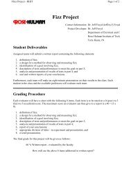
thereby producing the following diagram, denoted as Mohr’s Circle:<br />
σ x ′ y ′ (τ s)<br />
(σyy ,σxy)<br />
y − face <strong>stress</strong>es<br />
σp2<br />
�<br />
C<br />
a = σxx+σyy<br />
2<br />
r<br />
2<br />
A<br />
2θs<br />
2θp<br />
r =<br />
B<br />
�<br />
� σxx−σyy<br />
σp1<br />
Figure 5.7: Mohr’s Circle Parameters<br />
σ x ′ x ′ (σn)<br />
σp1 ,σp2 = principal <strong>stress</strong>es<br />
θ is positive counter clockwise<br />
2<br />
2<br />
+ σ 2 xy<br />
(σxx , −σyy)<br />
x − face <strong>stress</strong>es
5.1. STRESS TRANSFORMATIONS AND MOHR’S CIRCLE 111<br />
To plot Mohr’s <strong>circle</strong> given <strong>stress</strong>es σxx, σyy, σxy in the x-y coordinate system:<br />
� �<br />
σxx+σyy<br />
1. Find the center of Mohr’s <strong>circle</strong>; point A: 2 , 0 Note: σA = σxx+σyy<br />
2<br />
2. Plot <strong>stress</strong>es on x-face as point B ( σxx, −σxy ) <strong>and</strong> label as x-face. Note that point B<br />
corresponds to θ =0 ◦ in x-y plane.<br />
3. Plot <strong>stress</strong>es on y-face as point C ( σyy,σxy ) <strong>and</strong> label as y-face. Note that point C<br />
corresponds to θ =90 ◦ in x-y plane.<br />
4. Draw the <strong>circle</strong>. We note that while the x-face (θ =0 ◦ ) <strong>and</strong> the y-face (θ =90 ◦ ) are<br />
separated by 90 ◦ in the real world x-y coordinates, they appear as point B <strong>and</strong> C, respectively,<br />
in Mohr’s Circle <strong>and</strong> are 180 ◦ apart on Mohr’s Circle. Consequently, angles on Mohr’s Circle<br />
are twice that of the real x-y world. Itisalso important to note that θ =0 ◦ in the real world<br />
corresponds to the x-axis; however, in Mohr’s Circle the point θ =0 ◦ starts from the line AB<br />
since point B represents the <strong>stress</strong>es on the x-face θ =0 ◦ ). θ is positive CCW in both cases.<br />
5. Label principal <strong>stress</strong>es <strong>and</strong> maximum shear <strong>stress</strong>. Note: σP = σA±r <strong>and</strong> τSmax = ±r.<br />
There are two principal <strong>stress</strong>es σP 1 <strong>and</strong> σP 2 (planes where shear <strong>stress</strong> is zero) <strong>and</strong> two<br />
maximum shear <strong>stress</strong>es τSmax = ±r (top <strong>and</strong> bottom of <strong>circle</strong>). Note that σP 1 <strong>and</strong> σP 2 are<br />
180 ◦ apart on Mohr’s <strong>circle</strong>, but 90 ◦ in the real world. σP 1 is the normal <strong>stress</strong> in the x ′<br />
direction where x ′ is rotated by the angle θ (CCW) from the x-axis. σP 2 is in the y ′ direction.<br />
6. Identify the relative orientation between x-face (B) <strong>and</strong> the principal planes. Note<br />
that point B corresponds to the <strong>stress</strong>es on the x-face, i.e. θ =0◦ in the real world. For<br />
example, in the above 2θP = tan−1 � �<br />
σxy<br />
CCW from the x-face (from line A-B on Mohr’s<br />
σxx−σA<br />
Circle). Note: the writing of a specific formula is discouraged. It is far simpler (<strong>and</strong> usually<br />
less mistakes) to look at Mohr’s <strong>circle</strong> <strong>and</strong> apply trigonometry to calculate the angle.<br />
7. Identify the relative orientation between x-face (B) <strong>and</strong> the maximum shear planes.<br />
From Figure 5.7, 2θP +2θS =90 ◦ .ThusθS =45 ◦ − θP .From Figure 5.7, it easier to identify<br />
the principal shear <strong>stress</strong> planes as being −45 ◦ (real world) from the principal normal <strong>stress</strong><br />
plane (point B, bottom of <strong>circle</strong>) <strong>and</strong> +45 ◦ from the principal normal <strong>stress</strong> plane (top of<br />
<strong>circle</strong>). Note that the plane of max shear <strong>stress</strong> will generally have non-zero normal <strong>stress</strong>!<br />
8. Draw Free Body Diagrams with the x-face, principal plane, <strong>and</strong> the two maximum<br />
shear planes.<br />
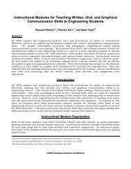
Example 5-1<br />
Consider the plane <strong>stress</strong> state given by the <strong>stress</strong> tensor:<br />
1. Determine center of <strong>circle</strong>, point A.<br />
[σ] =<br />
� 50 10<br />
10 20<br />
σA = σxx + σyy<br />
2<br />
= 50 + 20<br />
�<br />
ksi<br />
2<br />
2. Determine point B, x-face → ( σxx, −σxy )=(50, −10 )<br />
3. Determine point C, y-face → ( σyy,σxy )=(20, +10 )<br />
4. Draw Mohr’s <strong>circle</strong>:<br />
=35ksi
112 CHAPTER 5. STRESS TRANSFORMATION AND MOHR’S CIRCLE<br />
σ ( τ )<br />
xy ' '<br />
s<br />
(20,10)<br />
y-face<br />
50 ksi<br />
10 ksi<br />
(35,0)<br />
20 ksi<br />
20 ksi<br />
Figure 5.8:<br />
Figure 5.9:<br />
5. Compute principal <strong>stress</strong>es <strong>and</strong> max shear <strong>stress</strong>.<br />
r =<br />
�<br />
�σxx<br />
�2 − σyy<br />
+ σ2 xy =<br />
2<br />
10 ksi<br />
50 ksi<br />
(50,-10)<br />
x-face<br />
� �50 − 20<br />
2<br />
� 2<br />
σP = σA ± r =35± 18.03<br />
∴ σP 1 =35+18.03 =53.03 ksi<br />
σ ( τ )<br />
xx ' '<br />
n<br />
+10 2 =18.03 ksi
5.1. STRESS TRANSFORMATIONS AND MOHR’S CIRCLE 113<br />
σP 2 =35− 18.03 = 16.97 ksi<br />
τSmax = ±r = ±18.03 ksi<br />
Note that we have two principal <strong>stress</strong>es: σP 1 <strong>and</strong> σP 2. These are located 180◦ on Mohr’s<br />
<strong>circle</strong>, but 90◦ in the real world. In relation to the <strong>stress</strong> <strong>transformation</strong> equations (5.7), σP 1<br />
in the normal <strong>stress</strong> in x ′ -axis direction (which is oriented at an angle θP to the x-axis) <strong>and</strong><br />
σP 2 is the normal <strong>stress</strong> in the y ′ -axis direction. The planes of maximum shear occur 45◦ (real<br />
world) from the planes of principal <strong>stress</strong>.<br />
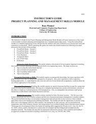
Plot the principal <strong>stress</strong>es <strong>and</strong> max shear <strong>stress</strong>es on Mohr’s Circle:<br />
σ ( τ )<br />
xy ' '<br />
σ =<br />
P2<br />
s<br />
(20,10)<br />
y-face<br />
16.97ksi<br />
τ<br />
S<br />
max<br />
τ<br />
S<br />
max<br />
= 18.03ksi<br />
(35,18.03)<br />
=<br />
(35,0)<br />
(35, 18.03)<br />
2θ S<br />
18.03ksi<br />
2θ P<br />
Figure 5.10:<br />
σ =<br />
P1<br />
(50,-10)<br />
x-face<br />
σ ( σ )<br />
xx ' '<br />
53.03ksi<br />
6. Identify orientation of planes for principal <strong>stress</strong>es relative to x-face plane.<br />
2θP = tan −1<br />
�<br />
σxy<br />
�<br />
= tan −1<br />
� �<br />
10<br />
=33.7deg 50 − 35<br />
σxx − σA<br />
∴ θP =16.85 deg CCW from x-face<br />
The plane for the second principal <strong>stress</strong> σP 2 is (θP + 90) deg CCW from x-face (real world).<br />
Note: In the above calculation, a formula was written down <strong>and</strong> used for 2θP . This is discouraged.<br />
It is far simpler (<strong>and</strong> usually less mistakes) to look at Mohr’s <strong>circle</strong> <strong>and</strong> apply<br />
trigonometry to calculate the angles.<br />
7. Identify orientation of planes for maximum shear <strong>stress</strong> (bottom of <strong>circle</strong>) relative to x-face<br />
plane.<br />
2θS =90deg − 2θP =90− 33.7 =56.3 deg<br />
n
114 CHAPTER 5. STRESS TRANSFORMATION AND MOHR’S CIRCLE<br />
∴ θS =28.15 deg CW from the x-face<br />
OR, plane of max shear <strong>stress</strong> (bottom of <strong>circle</strong>) is 45◦ CW in the real world from the principal<br />
<strong>stress</strong> plane with σP 1.<br />
Note: |σP | + |σS| =45deg (always!)<br />
Note that the plane of max shear <strong>stress</strong> will generally have non-zero normal <strong>stress</strong>! In this<br />
case, the plane of max shear <strong>stress</strong> has a normal <strong>stress</strong> σn =35ksi.<br />
8. Draw three free bodies: with the x-y <strong>stress</strong>es, with the principal <strong>stress</strong>es, <strong>and</strong> with the max<br />
shear <strong>stress</strong>es.<br />
50 ksi<br />
10<br />
ksi<br />
35 ksi<br />
18.03 ksi<br />
35 ksi<br />
Note the following:<br />
20<br />
ksi<br />
20<br />
ksi<br />
53.03 ksi<br />
35 ksi<br />
28.15 o<br />
10 ksi<br />
16.85 o<br />
50 ksi<br />
16.97 ksi<br />
o<br />
45<br />
18.03 ksi<br />
θ S =<br />
35 ksi<br />
53.03 ksi<br />
16.85 o<br />
θ =<br />
16.97 ksi<br />
28.15 o<br />
maximum shear<br />
<strong>stress</strong> planes<br />
Figure 5.11:<br />
The dark face is the<br />
original x-face as it is<br />
rotated.<br />
P<br />
principal<strong>stress</strong><br />
planes<br />
The shear <strong>stress</strong> on<br />
the rotated x-face is<br />
negative on Mohr’s<br />
<strong>circle</strong> <strong>and</strong> thus<br />
positive on the<strong>stress</strong><br />
cube. OR, negative<br />
shear <strong>stress</strong> on<br />
Mohr’s <strong>circle</strong> causes<br />
a CCW moment on<br />
the <strong>stress</strong> cube.
5.1. STRESS TRANSFORMATIONS AND MOHR’S CIRCLE 115<br />
• To obtain the orientation for principal <strong>stress</strong>es, the x-face has been rotated 16.85 deg CCW in<br />
the real world (33.7 deg on Mohr’s <strong>circle</strong>).<br />
• To obtain the orientation for maximum shear <strong>stress</strong>es, the x-face has been rotated 28.15 deg<br />
CW in the real world (56.3 deg on Mohr’s <strong>circle</strong>), OR, equivalently a rotation of 45 deg CW<br />
in the real world from the principal <strong>stress</strong> plane.<br />
Example 5-2<br />
Consider the same plane <strong>stress</strong> state given in Example 5-1:<br />
50 ksi<br />
10 ksi<br />
20 ksi<br />
20 ksi<br />
Figure 5.12:<br />
10 ksi<br />
50 ksi<br />
� �<br />
50 10<br />
[σ] =<br />
ksi<br />
10 20<br />
Values of principal <strong>stress</strong> <strong>and</strong> maximum shear <strong>stress</strong> obtain in Example 5-1 by Mohr’s <strong>circle</strong> must<br />
be identical to what would be obtained by using the <strong>stress</strong> <strong>transformation</strong> equations (5.7). This is<br />
true because Mohr’s <strong>circle</strong> is simply a graphical representation of equations (5.7). Use the <strong>stress</strong><br />
<strong>transformation</strong>s to determine the normal <strong>stress</strong> <strong>and</strong> shear <strong>stress</strong> for values of θ =16.85◦ , 106.85◦ ,<br />
−28.15◦ <strong>and</strong> verify that they correspond to the principal <strong>stress</strong> <strong>and</strong> maximum shear <strong>stress</strong> values<br />
obtained in Example 5-1.<br />
For θ =16.85◦ (same as 33.7◦ on Mohr’s <strong>circle</strong> from x-face, should equal σP 1)<br />
σx ′ x ′ = σxx cos 2 θ +2σxy sin θ cos θ + σyy sin 2 θ<br />
= (50 ksi) cos 2 16.85 ◦ + 2(10 ksi) sin 16.85 ◦ cos 16.85 ◦ + (20 ksi) sin 2 16.85 ◦ =53.03 ksi<br />
σx ′ y ′ = −(σxx − σyy) sin θ cos θ + σxy(cos 2 θ − sin 2 θ)<br />
= −(50 ksi − 20 ksi) sin 16.85 ◦ cos 16.85 ◦ +10ksi(cos 2 16.85 ◦ − sin 2 16.85 ◦ )=0ksi<br />
For θ = 106.85 ◦ (same as 213.7 ◦ on Mohr’s <strong>circle</strong> from x-face, should equal σP 2)<br />
σx ′ x ′ = σxx cos 2 θ +2σxy sin θ cos θ + σyy sin 2 θ<br />
= (50 ksi) cos 2 106.85 ◦ + 2(10 ksi) sin 106.85 ◦ cos 106.85 ◦ + (20 ksi) sin 2 106.85 ◦ =16.97 ksi<br />
σx ′ y ′ = −(σxx − σyy) sin θ cos θ + σxy(cos 2 θ − sin 2 θ)<br />
= −(50 ksi − 20 ksi) sin 106.85 ◦ cos 106.85 ◦ +10ksi(cos 2 106.85 ◦ − sin 2 106.85 ◦ )=0ksi<br />
For θ = −28.15 ◦ (same as −56.3 ◦ on Mohr’s <strong>circle</strong> from x-face, should equal τmax bottom of <strong>circle</strong>)<br />
σx ′ x ′ = (50 ksi) cos2 (−28.15 ◦ )+2(10 ksi) sin(−28.15 ◦ ) cos(−28.15 ◦ )+(20 ksi) sin 2 (−28.15 ◦ )=35ksi<br />
σx ′ y ′ = −(50 ksi − 20 ksi) sin(−28.15◦ ) cos(−28.15 ◦ )+10ksi(cos 2 (−28.15 ◦ ) − sin 2 (−28.15 ◦ )) = 18.03 ksi
116 CHAPTER 5. STRESS TRANSFORMATION AND MOHR’S CIRCLE<br />
For θ =40◦ (same as 80◦ on Mohr’s <strong>circle</strong> from x-face)<br />
σx ′ x ′ =47.45 ksi, σx ′ y ′ = −13.04 ksi (real world values). From, Mohr’s <strong>circle</strong> in Example 5-1,<br />
one obtains the same result. ⇐ Student, you should verify this! Note that this corresponds<br />
to a point 80 degrees CCW from the x-face on Mohr’s <strong>circle</strong> (or 46.3 degrees above the σn axis on<br />
Mohr’s <strong>circle</strong> ( 80, −33.7 )). Why is the sign negative on the value of σx ′ y ′ calculated from the <strong>stress</strong><br />
<strong>transformation</strong> equation? Remember that when you plot the x-face <strong>stress</strong>, a positive σxy (real world)<br />
is plotted as −σxy (point B on Mohr’s <strong>circle</strong>). Thus, a positive value of shear <strong>stress</strong> on Mohr’s <strong>circle</strong><br />
as we have for this case (θ =80◦CCW on Mohr’s <strong>circle</strong>) translates to a negative shear <strong>stress</strong> in the<br />
real world.<br />
σ ( τ )<br />
xy ' '<br />
σ =<br />
P2<br />
50 ksi<br />
s<br />
10 ksi<br />
(20,10)<br />
y-face<br />
16.97ksi<br />
20 ksi<br />
τ<br />
20 ksi<br />
S<br />
max<br />
τ<br />
10 ksi<br />
40 o<br />
= 18.03ksi<br />
(35,18.03)<br />
(35,0)<br />
35, 18.03<br />
S<br />
max<br />
=<br />
50 ksi<br />
18.03ksi<br />
22.55 ksi<br />
47.45 ksi<br />
80<br />
13.04 ksi<br />
Figure 5.13:<br />
47.45,13.04<br />
σ =<br />
P1<br />
(50,-10)<br />
x-face<br />
47.45 ksi<br />
40 o<br />
θ =<br />
σ ( σ )<br />
xx ' '<br />
13.04 ksi<br />
22.55 ksi<br />
53.03ksi<br />
n
5.1. STRESS TRANSFORMATIONS AND MOHR’S CIRCLE 117<br />
Example 5-3<br />
Consider the plane <strong>stress</strong> state given by the <strong>stress</strong> tensor:<br />
50 ksi<br />
10 ksi<br />
[σ] =<br />
1. Determine center of <strong>circle</strong>, point A.<br />
σA = σxx + σyy<br />
2<br />
20 ksi<br />
20 ksi<br />
Figure 5.14:<br />
� 50 −10<br />
−10 −20<br />
10 ksi<br />
�<br />
ksi<br />
50 ksi<br />
= 50+(−20)<br />
2<br />
=15ksi<br />
2. Determine point B, x-face → ( σxx, −σxy )=(50, −(−10) ) = ( 50, 10 )<br />
3. Determine point C, y-face → ( σyy,σxy )=(−20, −10 )<br />
4. Draw Mohr’s <strong>circle</strong>:<br />
5. Compute principal <strong>stress</strong>es <strong>and</strong> max shear <strong>stress</strong>.<br />
�<br />
�σxx<br />
�2 − σyy<br />
r =<br />
+ σ<br />
2<br />
2 �<br />
�50<br />
− (−20)<br />
xy =<br />
2<br />
σP = σA ± r =15± 36.4<br />
� 2<br />
∴ σP 1 =15+36.4 =51.4 ksi<br />
σP 2 =15− 36.4 =−21.4 ksi<br />
τSmax = ±r = ±36.4 ksi<br />
+(−10) 2 =36.4 ksi<br />
Note that we have two principal <strong>stress</strong>es: σP 1 <strong>and</strong> σP 2. These are located 180◦ on Mohr’s<br />
<strong>circle</strong>, but 90◦ in the real world. In relation to the <strong>stress</strong> <strong>transformation</strong> equations (5.7), σP 1<br />
in the normal <strong>stress</strong> in x ′ -axis direction (which is oriented at an angle θP to the x-axis) <strong>and</strong><br />
σP 2 is the normal <strong>stress</strong> in the y ′ -axis direction. The planes of maximum shear occur 45◦ (real<br />
world) from the planes of principal <strong>stress</strong>.<br />
Plot the principal <strong>stress</strong>es <strong>and</strong> max shear <strong>stress</strong>es on Mohr’s Circle:
118 CHAPTER 5. STRESS TRANSFORMATION AND MOHR’S CIRCLE<br />
σ =<br />
P2<br />
21.4ksi<br />
(-20,-10)<br />
y-face<br />
(-20,-10)<br />
y-face<br />
σ ( τ )<br />
xy ' '<br />
xy ' '<br />
(15,0)<br />
s<br />
σ ( τ )<br />
τ<br />
(15,0)<br />
s<br />
(15,36.4)<br />
(15, 36.4)<br />
S<br />
max<br />
=<br />
Figure 5.15:<br />
τ<br />
S<br />
max<br />
74.05<br />
36.4ksi<br />
(50,10)<br />
x-face<br />
= 36.4ksi<br />
15.95<br />
Figure 5.16:<br />
(50,10)<br />
x-face<br />
σ =<br />
P1<br />
σ ( σ )<br />
xx ' '<br />
51.4ksi<br />
n<br />
σ ( σ )<br />
xx ' '<br />
6. Identify orientation of planes for principal <strong>stress</strong>es relative to x-face plane.<br />
2θP = tan −1<br />
� �<br />
10<br />
=15.95 deg<br />
35<br />
n
5.2. GENERALIZED PLANE STRESS AND PRINCIPAL STRESSES 119<br />
∴ θP =7.97 deg CW from x-face<br />
The plane for the second principal <strong>stress</strong> σP 2 is (θP + 90)deg CCW from x-face (real world).<br />
7. Identify orientation of planes for maximum shear <strong>stress</strong> (bottom of <strong>circle</strong>) relative to x-face<br />
plane.<br />
2θS =90deg − 2θP =90− 15.95 = 74.05 deg<br />
∴ θS =37.03 deg CCW from the x-face<br />
or, plane of max shear <strong>stress</strong> (top of <strong>circle</strong>) is 45 ◦ CCW from plane with σP 1. Note that the<br />
plane of max shear <strong>stress</strong> will generally have non-zero normal <strong>stress</strong>! Inthis case, the plane of<br />
max shear <strong>stress</strong> has a normal <strong>stress</strong> σn =15ksi.<br />
8. Draw three free bodies: with the x-y <strong>stress</strong>es, with the principal <strong>stress</strong>es, <strong>and</strong> with the max<br />
shear <strong>stress</strong>es.<br />
Note the following:<br />
• To obtain the orientation for principal <strong>stress</strong>es, the x-face has been rotated 7.97 deg CW in<br />
the real world (15.95 deg on Mohr’s <strong>circle</strong>).<br />
• To obtain the orientation for maximum shear <strong>stress</strong>es, the x-face has been rotated 37.03 deg<br />
CCW in the real world (74.05 deg on Mohr’s <strong>circle</strong>), or, equivalently a rotation of 45 deg CCW<br />
in the real world from the principal <strong>stress</strong> plane.<br />
5.2 Generalized Plane Stress <strong>and</strong> Principal Stresses<br />
In the x-y plane, any set of <strong>stress</strong>es ( σxx,σyy,σxy ) can be represented by a Mohr’s Circle as was<br />
shown previously <strong>and</strong> as shown in Figure 5.18 below (the dark <strong>circle</strong>). Corresponding to these x-y<br />
<strong>stress</strong>es, there are two principal <strong>stress</strong>es ( σP 1,σP 2 ) which also define the same Mohr’s Circle with<br />
coordinates of ( σP 1, 0) <strong>and</strong> ( σP 2, 0). Thus, the <strong>circle</strong> is (or can be) defined by any two principal<br />
<strong>stress</strong>es as they form the diameter of the <strong>circle</strong>. It follows that the Mohr’s <strong>circle</strong> for the x-z plane<br />
would also be formed by the principal <strong>stress</strong>es in the x-z plane, in this case σP 1 <strong>and</strong> σP 3. Similarly,<br />
Mohr’s <strong>circle</strong> in the y-z plane is defined by σP 2 <strong>and</strong> σP 3. Wecan draw all three of these <strong>circle</strong>s on<br />
one diagram as shown below.<br />
If the value of the third principal <strong>stress</strong> is less than the second, or greater than the first, we<br />
obtain a larger <strong>circle</strong> than the <strong>circle</strong> obtain for the x-y plane <strong>and</strong> hence the maximum shear <strong>stress</strong><br />
is also larger. For the case in the figure above, even if the out-of-plane normal <strong>stress</strong> σzz =0,one<br />
obtains a larger maximum shear <strong>stress</strong> than was obtained from the x-y plane.<br />
Forageneral <strong>stress</strong> tensor (3-D), it can be shown that the principal <strong>stress</strong>es are defined by the<br />
following eigenvalue problem:<br />
�<br />
�<br />
�<br />
�<br />
�<br />
�<br />
|[σ] − σP [I]| =0<br />
(σxx − σP ) σxy σxz<br />
σyx (σyy − σP ) σyz<br />
σzx σzy (σzz − σP )<br />
�<br />
�<br />
�<br />
�<br />
�<br />
� =0<br />
After the 9 components of <strong>stress</strong> ( σxx,σxy,... ,σzz ) are substituted into the above, the determinant<br />
can be exp<strong>and</strong>ed to obtain a cubic polynomial in σP which will �yield<br />
the three principal <strong>stress</strong><br />
�<br />
values σP 1, σP 2, σP 3. For2-D (x-y plane), the determinant reduces to �<br />
� (σxx<br />
�<br />
− σP ) σxy �<br />
�<br />
σyx (σyy − σP ) � =<br />
0 which results in two principal <strong>stress</strong> values σP 1, σP 2.
120 CHAPTER 5. STRESS TRANSFORMATION AND MOHR’S CIRCLE<br />
50 ksi<br />
51.4 ksi<br />
10 ksi<br />
21.4 ksi<br />
20 ksi<br />
21.4 ksi<br />
20 ksi<br />
45<br />
36.4 ksi<br />
10 ksi<br />
7.97<br />
51.4 ksi<br />
50 ksi<br />
15 ksi<br />
principal<strong>stress</strong><br />
planes<br />
15 ksi<br />
36.4 ksi<br />
15 ksi 15 ksi<br />
37.03<br />
Figure 5.17:<br />
Example 5-4<br />
maximumshear<br />
<strong>stress</strong> planes<br />
Same as Example 5-1 except a z component of <strong>stress</strong> is added to make the problem a generalized<br />
plane <strong>stress</strong> problem. The generalized plane <strong>stress</strong> state is given by the <strong>stress</strong> tensor:
5.2. GENERALIZED PLANE STRESS AND PRINCIPAL STRESSES 121<br />
σ P3<br />
( σ zz ,0)<br />
σ ( τ )<br />
x'y' s<br />
τ<br />
S max<br />
( generalized plane <strong>stress</strong>)<br />
r<br />
σ σ<br />
( , − )<br />
xx xy<br />
σ P2<br />
2θ P<br />
P1<br />
( σ , σ )<br />
yy<br />
xy<br />
2θ S<br />
τ S<br />
max<br />
σ ( σ )<br />
σ xx ' ' n<br />
Figure 5.18: Mohr’s Circle for Generalized Plane Stress (plane <strong>stress</strong> in x-y plane)<br />
⎡<br />
[σ] = ⎣<br />
50 10 0<br />
10 20 0<br />
0 0 −10<br />
⎤<br />
⎦ ksi<br />
Steps 1-7 will be identical to Example 5-1 for the x-y plane (since both examples have exactly<br />
the same <strong>stress</strong> components in the x-y plane). Hence, for the x-y plane we obtain Mohr’s <strong>circle</strong>:<br />
To complete the solution we note that there are no shear <strong>stress</strong>es in the z plane <strong>and</strong> hence σzz<br />
is automatically a principal <strong>stress</strong>. Thus, σP 3 = σzz = −10. Adding the third principal <strong>stress</strong> to<br />
Mohr’s <strong>circle</strong>, we obtain:<br />
Hence, the principal <strong>stress</strong>es are σP = −10, 16.97, 53.03 ksi. The maximum shear <strong>stress</strong> is the<br />
radius of the largest Mohr’s <strong>circle</strong>. Thus, τSmax = 53.03+10<br />
2 =31.52 ksi. In order to “change” <strong>circle</strong>s,<br />
we need to be in the principal orientation, because this is the same on all three <strong>circle</strong>s. The sketches<br />
below illustrate this “changing” process. Note that when changing views, there is NOT a change in<br />
the <strong>stress</strong>es, only in the way they are viewed. If we had rotated 45◦ off the principal plane P1 − P2,<br />
we would have still been on the smaller <strong>circle</strong> <strong>and</strong> therefore could never attain the maximum shear<br />
<strong>stress</strong>.
122 CHAPTER 5. STRESS TRANSFORMATION AND MOHR’S CIRCLE<br />
σ ( τ )<br />
xy ' '<br />
σ =<br />
P2<br />
σ ( τ )<br />
xy ' '<br />
s<br />
σ =<br />
P3<br />
s<br />
(20,10)<br />
y-face<br />
16.97ksi<br />
10ksi<br />
(20,10)<br />
y-face<br />
τ<br />
S<br />
max<br />
τ<br />
σ =<br />
P2<br />
S<br />
max<br />
τ<br />
= 18.03ksi<br />
(35,18.03)<br />
=<br />
(35,0)<br />
(35, 18.03)<br />
τ<br />
S<br />
max<br />
16.97ksi<br />
S<br />
max<br />
2θ S<br />
18.03ksi<br />
16.85<br />
Figure 5.19:<br />
= 31.52ksi<br />
(35,18.03)<br />
(35,0)<br />
(35, 18.03)<br />
= 31.52ksi<br />
2θ S<br />
σ =<br />
P1<br />
(50,-10)<br />
x-face<br />
16.85<br />
Figure 5.20:<br />
Example 5-5<br />
σ =<br />
(50,-10)<br />
x-face<br />
σ ( σ )<br />
xx ' '<br />
53.03ksi<br />
P1<br />
xx ''<br />
n<br />
σ ( σ )<br />
53.03ksi<br />
Given the <strong>stress</strong> state below, use Mohr’s <strong>circle</strong> to find the principal planes <strong>and</strong> maximum shear<br />
n
5.2. GENERALIZED PLANE STRESS AND PRINCIPAL STRESSES 123<br />
50 ksi<br />
z<br />
y<br />
10 ksi<br />
P1<br />
P2<br />
<strong>stress</strong>es.<br />
Uniaxial Stress<br />
10 ksi<br />
P2<br />
x<br />
20 ksi<br />
Vie w AA:<br />
53.03 ksi<br />
-10 ksi<br />
20 ksi<br />
8.425 o<br />
53.03 ksi<br />
P1<br />
P ( inzdirection)<br />
3<br />
P3<br />
16.97 ksi<br />
53.03 ksi<br />
10<br />
ksi<br />
10 ksi<br />
45<br />
21.515 ksi<br />
50 ksi<br />
16.97 ksi<br />
-10 ksi<br />
principal<strong>stress</strong><br />
planes<br />
16.97 ksi<br />
AA<br />
21.515 ksi<br />
31.52 ksi<br />
16.97 ksi<br />
Figure 5.21:<br />
⎡<br />
[σ] = ⎣<br />
σxx 0 0<br />
0 0 0<br />
0 0 0<br />
53.03 ksi<br />
21.515 ksi<br />
⎤<br />
⎦<br />
21.515 ksi<br />
principal<strong>stress</strong><br />
planes<br />
maximumshear<br />
<strong>stress</strong> planes
124 CHAPTER 5. STRESS TRANSFORMATION AND MOHR’S CIRCLE<br />
y-face<br />
(0,0)<br />
σ x ′ y ′<br />
B<br />
C<br />
2.5<br />
5MPa<br />
x-face<br />
z<br />
2.5<br />
y<br />
2.5<br />
σ x ′ x ′<br />
Figure 5.22:<br />
• Maximum shear traction at 45 ◦ from x-axis<br />
• Maximum normal traction along x-axis<br />
Example 5-6<br />
x<br />
45<br />
C B<br />
σxx<br />
σ x ′ x ′ = σn =2.5<br />
σ x ′ y ′ = τ s =2.5<br />
Given: The state of <strong>stress</strong> at each point in a bar can be represented by the <strong>stress</strong> tensor [σ]:<br />
Required :<br />
⎡<br />
[σ] = ⎣<br />
z<br />
σxx 0 0<br />
0 0 0<br />
0 0 0<br />
y<br />
⎤ ⎡<br />
⎦ = ⎣<br />
x<br />
Figure 5.23:<br />
a) Construct Mohr’s Circle for the given <strong>stress</strong> tensor.<br />
10 kN<br />
m 2 0 0<br />
0 0 0<br />
0 0 0<br />
b) What are the traction vectors experienced each face of the cube?<br />
⎤<br />
⎦
5.2. GENERALIZED PLANE STRESS AND PRINCIPAL STRESSES 125<br />
c) What are the normal <strong>and</strong> shear components of these traction vectors?<br />
d) What is the maximum shear <strong>stress</strong> experienced by the bar?<br />
e) What is the orientation of the surface that experiences this maximum shear <strong>stress</strong>?<br />
f) What is the maximum normal <strong>stress</strong> experienced by the bar?<br />
a) Use the steps mentioned in the above text.<br />
b) ti =10i<br />
tj = 0<br />
tk = 0<br />
Maximum Normal<br />
y-face<br />
C(0,0)<br />
c) σxx =10<br />
σxy = σyz = σzz = σyy =0<br />
σ<br />
xy ' '<br />
d) 5 kN<br />
m 2 at the points ( 5, 5) <strong>and</strong> (5, −5)<br />
Solution<br />
MaximumShear<br />
(5,5)<br />
A(5,0)<br />
Figure 5.24:<br />
(5,-5)<br />
MaximumShear<br />
Maximum Normal<br />
x-face<br />
B(10,0)<br />
e) The surface is tilted at 45 ◦ to the x-axis (90 ◦ in Mohr space is 45 ◦ in real space).<br />
f) 10 kN<br />
m 2 at the points ( 10, 0) <strong>and</strong> (0, 0)<br />
Example 5-7<br />
Given: 2-D Stress State – Ignore the z components of <strong>stress</strong>.<br />
Required :<br />
⎡<br />
[σ] = ⎣<br />
σxx σxy 0<br />
σyx σyy 0<br />
0 0 0<br />
⎤ ⎡<br />
⎦ = ⎣<br />
a) Construct Mohr’s Circle for the given <strong>stress</strong> tensor.<br />
6 2 0<br />
2 6 0<br />
0 0 0<br />
σ xx ' '<br />
⎤<br />
⎦ MPa<br />
b) What is the orientation of the surface when the maximum shear <strong>stress</strong> is obtained?<br />
c) What is the maximum shear <strong>stress</strong> experienced by the bar?
126 CHAPTER 5. STRESS TRANSFORMATION AND MOHR’S CIRCLE<br />
a)<br />
b) 0 ◦<br />
z<br />
y<br />
σ xy ' '<br />
Maximum Normal<br />
c) 2 MPa at points ( 6, 2) <strong>and</strong> (6, −2)<br />
x<br />
σyy =6<br />
σyx =2<br />
Figure 5.25:<br />
Maximum Shear<br />
x-face<br />
B(6,2)<br />
A(6,0)<br />
Figure 5.26:<br />
Solution<br />
σxy =2<br />
C(6,-2)<br />
y-face<br />
Maximum Shear<br />
σxx =6<br />
Maximum normal<br />
σ xx ' '
5.2. GENERALIZED PLANE STRESS AND PRINCIPAL STRESSES 127<br />
Deep Thought
128 CHAPTER 5. STRESS TRANSFORMATION AND MOHR’S CIRCLE<br />
5.3 Questions<br />
5.1 Describe in your own words the meaning of principal <strong>stress</strong>.<br />
5.2 What is the angle between the planes of principal <strong>stress</strong> <strong>and</strong> maximum shear <strong>stress</strong> in a body?<br />
Why is it that way?<br />
5.3 What is the main point of Mohr’s <strong>circle</strong>?<br />
5.4 What does the term t (n) in Caucy’s formula physically represent?<br />
5.5 When considering Mohr’s <strong>circle</strong>, explain physically the <strong>stress</strong> state defined by the point on<br />
Mohr’s Circle that lies on the horizontal axis.<br />
5.4 Problems<br />
5.6 GIVEN :Amaterial point is known to be in a state of generalized plane <strong>stress</strong> as given by:<br />
⎡<br />
4 −2 0<br />
⎤<br />
[σ] = ⎣ −2 −5 0 ⎦ MPa<br />
0 0 −3<br />
REQUIRED: Draw all important sketches, showing planes of maximum shear as well as principal<br />
planes.<br />
5.7 GIVEN : The <strong>stress</strong> tensor as follows:<br />
REQUIRED:<br />
⎡<br />
[σ] = ⎣<br />
3 0 0<br />
0 19 0<br />
0 0 0<br />
⎤<br />
⎦ ksi<br />
(a) compute the three principal <strong>stress</strong>es <strong>and</strong> maximum shear <strong>stress</strong>;<br />
(b) indicate the maximum shear direction.<br />
5.8 The state of <strong>stress</strong> at a certain point of a body is given by<br />
⎡<br />
1 2 0<br />
⎤<br />
[σ] = ⎣ 2 7 0 ⎦ MPa<br />
0 0 0<br />
5.9<br />
Determine on which planes:<br />
i) principal <strong>stress</strong>es occur<br />
ii) shearing <strong>stress</strong> is greatest.<br />
⎡<br />
[σ] = ⎣<br />
Find maximum shear <strong>and</strong> normal <strong>stress</strong>es.<br />
5.10 (a) What is a principal plane?<br />
σxx 0 0<br />
0 0 0<br />
0 0 0<br />
⎤<br />
⎦ psi
5.4. PROBLEMS 129<br />
725 psi<br />
z<br />
Problem 5.9<br />
(b) Are the following <strong>stress</strong> tensors generalized plane <strong>stress</strong> cases? Answer in yes/no.<br />
5.11 GIVEN :<br />
⎡<br />
i) ⎣<br />
⎡<br />
iii) ⎣<br />
1 0 −3<br />
0 2 0<br />
−3 0 −5<br />
1 0 0<br />
0 0 −1<br />
0 −1 6<br />
⎡<br />
[σ] = ⎣<br />
y<br />
⎤ ⎡<br />
⎦ ii) ⎣<br />
⎤ ⎡<br />
⎦ iv) ⎣<br />
2 0 0<br />
0 −8 0<br />
0 0 10<br />
x<br />
4<br />
2<br />
2<br />
−3<br />
0<br />
1<br />
0 1 2<br />
−2 0 2<br />
0 3 7<br />
2 7 5<br />
⎤<br />
⎦ ksi<br />
(a) Write out the three principal <strong>stress</strong>es <strong>and</strong> compute the maximum shear <strong>stress</strong>.<br />
(b) What is the maximum shear direction <strong>and</strong> on what plane is it acting in?<br />
5.12 GIVEN :<br />
[σ] =<br />
� −5 −5<br />
−5 5<br />
�<br />
MPa<br />
(a) Draw the corresponding <strong>stress</strong> cube.<br />
(b) Construct the three Mohr’s <strong>circle</strong>s for the given <strong>stress</strong> state.<br />
(c) Compute the two principal <strong>stress</strong>es <strong>and</strong> maximum shear <strong>stress</strong>.<br />
(d) Using the formula given below, determine the normal <strong>stress</strong>, which acts upon a surface<br />
corresponding to a 30◦ clockwise rotation of the x-face.<br />
� �<br />
� �<br />
σxx − σyy<br />
σxx + σyy<br />
σn =<br />
cos 2θ + σxy sin 2θ +<br />
2<br />
2<br />
5.13 GIVEN :Amaterial in the following state of plane <strong>stress</strong>:<br />
⎡<br />
−2500<br />
[σ] = ⎣ 0<br />
0<br />
0<br />
0<br />
0<br />
⎤<br />
⎦ ksi<br />
0 0 0<br />
REQUIRED: Draw all important sketches, showing planes of maximum shear <strong>stress</strong> as well as<br />
principal planes.<br />
⎤<br />
⎦<br />
⎤<br />
⎦<br />
σ xx
130 CHAPTER 5. STRESS TRANSFORMATION AND MOHR’S CIRCLE<br />
5.14 Using the following 2-D <strong>stress</strong> state at a point in a body,<br />
⎡<br />
50 0<br />
⎤<br />
0<br />
[σ] = ⎣ 0 −50 0 ⎦ MPa<br />
0 0 0<br />
Find:<br />
a) tn for n = i, n = j, <strong>and</strong> n = 1<br />
2<br />
�√ 3i + j �<br />
b) If the coordinate axes were rotated 45 degrees clockwise, to x ′ -y ′ , solve for the new values<br />
of σx ′ x ′, σy ′ y ′, σx ′ y ′. Use Cauchy’s Formula.<br />
c) Construct the three Mohr’s <strong>circle</strong>s for the given <strong>stress</strong> state.<br />
5.15 The state of <strong>stress</strong> at a certain point of a body is given by<br />
⎡<br />
3 −1 4<br />
⎤<br />
[σ] = ⎣ −1 2 0 ⎦ ksi<br />
4 0 −2<br />
i) Find the traction vector on the plane whose normal is in the direction i +2j +2k<br />
ii) Find the traction vector on the plane whose normal is in the direction 4i − 3j + k<br />
iii) Determine the normal <strong>and</strong> shearing components of the traction vector on the above planes.<br />
5.16 For a <strong>stress</strong> state defined by: σxx =10MPa,σxy = σyx =40MPa,σyy =50MPa. Define:<br />
a) the value of the Principal Stress<br />
b) the maximum Shear Stress <strong>and</strong> corresponding Normal Stress<br />
5.17 GIVEN :Athin-walled cylindrical pressure vessel is subjected to internal pressure, p<br />
θ<br />
p =500psi r = 10in t =0.25in<br />
t =wall thickness<br />
r =cylinder radius<br />
x<br />
Problem 5.17<br />
It can It can be shown that the <strong>stress</strong> state is given by a hoop (circumferential) <strong>stress</strong> σθθ = pr<br />
t<br />
<strong>and</strong> an axial <strong>stress</strong> (along the axis of pressure vessel) of σxx = pr<br />
2t :<br />
REQUIRED: Draw all important sketches, showing planes of maximum shear as well as principal<br />
planes.<br />
5.18 GIVEN : Suppose that the pressure vessel of 5.17 is also subjected to an end torque, Mt.<br />
The <strong>stress</strong> state be shown by:<br />
REQURIED: Draw all important sketches, showing planes of maximum shear as well as principal<br />
planes.<br />
pr<br />
t<br />
pr<br />
2t
5.4. PROBLEMS 131<br />
M t = 1, 000, 000 lb-in<br />
3<br />
J = 2π<br />
r t<br />
M t<br />
Problem 5.18<br />
5.19 GIVEN : The following <strong>stress</strong> tensor in Cartesian coordinates<br />
⎡<br />
5 −2 0<br />
⎤<br />
[σ] = ⎣ −2 −1 0 ⎦ MPa<br />
0 0 −3<br />
REQUIRED:<br />
a) Sketch the <strong>stress</strong> cube representation<br />
b) Construct the three Mohr’s <strong>circle</strong>s<br />
c) Determine the traction vectors: t (i), t (j), t (k)<br />
d) Make a sketch of t (i), t (j), t (k) acting on the appropriate plane(s)<br />
5.20 GIVEN :Amaterial point is known to be in a state of generalized plane <strong>stress</strong> as given by:<br />
⎡<br />
−1 −2 0<br />
⎤<br />
[σ] = ⎣ −2 3 0 ⎦ ksi<br />
0 0 4<br />
REQUIRED:<br />
1) Construct the three Mohr’s <strong>circle</strong>s.<br />
2) Find the three principal <strong>stress</strong>es <strong>and</strong> the maximum shear <strong>stress</strong>.<br />
3) Draw all important sketches, showing planes of maximum shear as well as principal planes<br />
with the associated coordinate rotations labeled properly.<br />
5.21 GIVEN : The state of <strong>stress</strong> at a certain point on a body is given by:<br />
a)<br />
⎡<br />
4<br />
[σ] = ⎣ 2<br />
2<br />
−3<br />
0<br />
1<br />
⎤<br />
⎦<br />
b)<br />
0<br />
⎡<br />
−2<br />
[σ] = ⎣ 0<br />
1<br />
0<br />
3<br />
2<br />
2<br />
7<br />
⎤<br />
⎦<br />
2 7 5<br />
REQUIRED: Determine for both a) <strong>and</strong> b) on which of the three coordinate planes:<br />
1) Normal <strong>stress</strong> is greatest<br />
2) Shear <strong>stress</strong> is greatest<br />
pr<br />
t<br />
Mr t<br />
J<br />
pr<br />
2t
132 CHAPTER 5. STRESS TRANSFORMATION AND MOHR’S CIRCLE<br />
5.22 Use Cauchy’s Formula, tn = σ · n, for the following <strong>stress</strong> tensor<br />
⎡<br />
20<br />
[σ] = ⎣ 5<br />
5<br />
−6<br />
0<br />
0<br />
⎤<br />
⎦ ksi n = cos θi + sin θj +0k<br />
0 0 0<br />
REQUIRED:<br />
a) The plane at which the shear <strong>stress</strong> equals zero, i.e., the angle in the unit normal which<br />
describes the plane for the following <strong>stress</strong> tensor.<br />
b) The normal <strong>stress</strong> on the face described by the plane found in part a). What is this<br />
normal <strong>stress</strong> called?<br />
c) At what angle is the plane of maximum shear <strong>stress</strong> from the principal <strong>stress</strong> plane.<br />
d) What is the value of the maximum shear <strong>stress</strong> for the <strong>stress</strong> tensor given above.<br />
5.23 GIVEN : The state of <strong>stress</strong> at each point in a bar can be represented by the <strong>stress</strong> tensor [σ]:<br />
⎡<br />
[σ] = ⎣ σxx<br />
0<br />
0<br />
0<br />
⎤ ⎡<br />
kN<br />
0 8 m<br />
0 ⎦ = ⎣<br />
0 0 0<br />
2 0<br />
0<br />
0<br />
⎤<br />
0<br />
0 ⎦<br />
0 0 0<br />
REQUIRED:<br />
z<br />
y<br />
x<br />
σxx<br />
Problem 5.23<br />
σxx =8 � kN<br />
m2 �<br />
a) What are the traction vectors experienced by faces in other orientations?<br />
b) What are the normal <strong>and</strong> shear components of these traction vectors?<br />
c) What is the maximum shear <strong>stress</strong> experienced by the bar?<br />
d) What is the orientation of the surface that experiences this maximum shear <strong>stress</strong>?<br />
e) What is the maximum normal <strong>stress</strong> experienced by the bar?<br />
5.24 GIVEN :<br />
REQUIRED:<br />
⎡<br />
[σ] = ⎣<br />
σxx σxy 0<br />
σyx σyy 0<br />
0 0 0<br />
⎤ ⎡<br />
⎦ = ⎣<br />
3 1 0<br />
1 3 0<br />
0 0 0<br />
⎤<br />
⎦ MPa<br />
a) Construct Mohr’s <strong>circle</strong> for the given <strong>stress</strong> tensor.<br />
b) What is the orientation of the surface when the maximum shear <strong>stress</strong> is obtained?<br />
c) What is the maximum shear <strong>stress</strong> experienced by the bar?
5.4. PROBLEMS 133<br />
z<br />
y<br />
x<br />
σyy =3<br />
σyx =1<br />
Problem 5.24<br />
5.25 The state of <strong>stress</strong> at a certain point of a body is given by<br />
⎡<br />
−1<br />
[σ] = ⎣ −2<br />
−2<br />
3<br />
⎤<br />
0<br />
0 ⎦ MPa<br />
0 0 4<br />
σxy =1<br />
σxx =3<br />
a) Calculate the values of the corresponding principal <strong>stress</strong>es.<br />
b) Indicate the magnitude of the maximum shear <strong>stress</strong> in the x-y plane.<br />
c) Draw the x-y plane including 1) principal <strong>stress</strong>es <strong>and</strong> 2) max shear <strong>stress</strong>. In each case,<br />
indicate the magnitude of all <strong>stress</strong>es <strong>and</strong> the angle the element is rotated relative to the<br />
original x-face.<br />
d) Determine the magnitude of the maximum shear <strong>stress</strong> considering all planes.<br />
e) If the material’s failure criteria is given by a6MPanormal <strong>stress</strong> <strong>and</strong> 3 MPa shear <strong>stress</strong>.<br />
Indicate if the material will fail under the applied load <strong>and</strong> if so, whether it is due to<br />
shear or normal <strong>stress</strong>.<br />
5.26 Repeat problem 5.25 for:<br />
⎡<br />
[σ] = ⎣<br />
5 3 0<br />
3 2 0<br />
0 0 0<br />
⎤<br />
⎦ MPa<br />
Remember to consider the problem as a case of Generalized Plane Stress.<br />
5.27 GIVEN : <strong>stress</strong> tensors as follows<br />
⎡<br />
5 0<br />
⎤<br />
0<br />
⎡<br />
(1) ⎣ 0 2 0 ⎦ (2) ⎣<br />
0 0 0<br />
REQUIRED:<br />
4 0 0<br />
0 4 0<br />
0 0 4<br />
⎤ ⎡<br />
⎦ (3) ⎣<br />
3 −3 0<br />
−3 0 0<br />
0 0 −2<br />
(a) sketch the <strong>stress</strong> cube aligned with the coordinate axes (Cartesian coordinate system)<br />
<strong>and</strong> the values of all shear <strong>and</strong> normal <strong>stress</strong>es on its surfaces;<br />
(b) construct the three Mohr’s <strong>circle</strong>s for the <strong>stress</strong> state;<br />
(c) sketch a <strong>stress</strong> cube oriented so that it is aligned with the principal axes <strong>and</strong> indicate its<br />
angle relative to the x-face <strong>and</strong> the principal <strong>stress</strong>es which act upon it;<br />
(d) determine the maximum shear <strong>and</strong> normal <strong>stress</strong>es experienced by the material which is<br />
subjected to this <strong>stress</strong> state <strong>and</strong> for each of these <strong>stress</strong>es, indicate the orientation of the<br />
surface which experiences this <strong>stress</strong>;<br />
⎤<br />
⎦
134 CHAPTER 5. STRESS TRANSFORMATION AND MOHR’S CIRCLE<br />
(e) determine the shear <strong>and</strong> normal <strong>stress</strong>es that act upon a surface which corresponding to<br />
a30 ◦ counter-clockwise rotation of the x-face about z-axis.<br />
5.28 For the given simply supported beam as pictured below, with length L =10m,thickness<br />
h =0.1 m,cross sectional area A =0.01 m2 <strong>and</strong> a distributed load Po =10 kN<br />
m ,a<strong>stress</strong><br />
analysis indicates a <strong>stress</strong> of σxx = −2 MPa,σxy = −1 MPa,σyy =4MPaatx =5m,<br />
y =0.05 m. Repeat the <strong>stress</strong> analysis described in problem 5.27.<br />
5.29 Derive an equation for σy ′ y ′ by h<strong>and</strong>.<br />
5.30 Using Scientific Workplace:<br />
h<br />
a) evaluate σx ′ x ′, σy ′ y ′, σx ′ y ′, σy ′ x ′<br />
y<br />
L<br />
Po<br />
Problem 5.28<br />
b) verify that σx ′ y ′ = σy ′ x ′ (assume σxy = σyx)<br />
c) Graph σx ′ x ′(θ), σx ′ y ′(θ) for 0
5.4. PROBLEMS 135<br />
h<br />
2<br />
h<br />
2<br />
x<br />
REQUIRED:<br />
y<br />
y<br />
5MPa<br />
Problem 5.31<br />
L<br />
σ yy<br />
Problem 5.32<br />
3MPa<br />
σ xy<br />
10 MPa<br />
1) Verify that the conservation of angular momentum <strong>and</strong> linear momentum are satisfied<br />
under static conditions, in the absence of body forces, at every point ( x, y )onthe plate.<br />
2) Find the components of the traction vector applied on the faces: x =0,x = L, y = h<br />
2 ,<br />
y = − h<br />
2<br />
5.33 For the following structure <strong>and</strong> the applied load F, the <strong>stress</strong> state in a rectangular Cartesian<br />
coordinate system at point P is given by the specified <strong>stress</strong> tensor [σ].<br />
⎡<br />
5<br />
[σ] = ⎣ 2<br />
2<br />
−1<br />
0<br />
0<br />
⎤<br />
⎦ MPa<br />
0 0 −3<br />
a) Sketch the <strong>stress</strong> cube representation. Label all the components, planes <strong>and</strong> points of<br />
interest.<br />
b) Determine the values of the Principal Stresses.<br />
c) Specify the required rotation (in terms of the normal to the x-face) in order to achieve<br />
maximum shear <strong>stress</strong> in the xy face. Make a sketch of the xy face showing the components<br />
of <strong>stress</strong> <strong>and</strong> the angle rotated.<br />
σ xx<br />
x
136 CHAPTER 5. STRESS TRANSFORMATION AND MOHR’S CIRCLE<br />
z<br />
y<br />
P<br />
F<br />
Problem 5.33<br />
d) According to the material’s properties, the failure criteria is given by a maximum <strong>stress</strong><br />
of 4 MPa for shear <strong>and</strong> 6 MPa for normal <strong>stress</strong>. Predict if the material will fail due to<br />
the applied load. Why?<br />
x