Serial Communications Protocol Specifications - Swissvacuum.com
Serial Communications Protocol Specifications - Swissvacuum.com
Serial Communications Protocol Specifications - Swissvacuum.com

You also want an ePaper? Increase the reach of your titles
YUMPU automatically turns print PDFs into web optimized ePapers that Google loves.
0 193 129 64 1 192 128 65<br />
0 193 129 64 1 192 128 65<br />
1 192 128 65 0 193 129 64<br />
1 192 128 65 0 193 129 64<br />
0 193 129 64 1 192 128 65<br />
1 192 128 65 0 193 129 64<br />
0 193 129 64 1 192 128 65<br />
0 193 129 64 1 192 128 65<br />
1 192 128 65 0 193 129 64<br />
MICROPLC MEMORY LAYOUT VERS. 2.0<br />
- 25 -<br />
NOTE:<br />
It's very important that writing operations in microPLC are correct and right. In effect it is absolutely<br />
important that the data written to the microPLC are correct from the format point of view and from the<br />
addresses point of view.<br />
Wrong data or wrong addresses for data can be very dangeorus for the functionality of the controller.<br />
It is operator's liability to make sure that all safety conditions are guaranteed, in order to avoid damages to<br />
the chamber controller and chamber devicecs or to prevent its right functioning through wrong operations.<br />
ANGELANTONI Industrie doesn't take any liability on itself, neither directly or inderectly, about problems<br />
caused by bad functioning due to software development based on this manual.<br />
In the following section the memory layout of the chamber controller version 2.00 is shown<br />
In this version the entire area available to the user is divided in two different sections, the first of them dedicated only<br />
for reading and the second one for writing.<br />
Please, note that the microPLC controller provides a wide range of facilities and only a sub-set of these is really used<br />
to control Hygros e Challenge chambers (also called “standard chambers”).<br />
Specifically, standard chambers use 2 regulators (and so only 2 channels for measuring and setting operations).<br />
Non standard chambers could use more deeply the facilities <strong>com</strong>ing from the microPLC, according to the customer<br />
requirements. If this is the case, a manual appendix will be available together with this manual, to specify the<br />
controller memory area really used.<br />
The following section of this manual only refers to standard chambers, even if the general memory layout is shown.<br />
The PC software normally reads the reading area in order to know the status (measures, actiovations, alarms) of the<br />
chamber.<br />
When a new status for the chamber is required (for example, the user wants to change the temperature set for the<br />
chamber from 35 to 75 Celsius degree), the PC software makes a query to the microPLC, writing data into the<br />
writing area. When done, the PC software simply turn back to its normal task: reading from the chamber.<br />
According to the data sent by the PC, chamber controller will try to act in order to satisfy the user requests, if<br />
possible.<br />
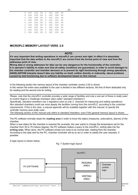
A logic layout is shown below:<br />
PC SOFTWARE<br />
Fig. 7 System logic layout<br />
microPLC<br />
READING<br />
AREA<br />
WRITING<br />
AREA<br />
Chamber<br />
control<br />
logic<br />
<strong>Serial</strong> <strong>com</strong>munications protocol vers. 2.02 Angelantoni Industrie Spa Massa Martana (PG) Italy