Eclipse Engineering Guide
Eclipse Engineering Guide
Eclipse Engineering Guide

You also want an ePaper? Increase the reach of your titles
YUMPU automatically turns print PDFs into web optimized ePapers that Google loves.
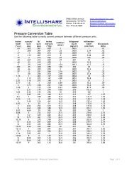
SIMPLIFIED SELECTION OF AIR, GAS AND MIXTURE PIPING SIZE<br />
Air, gas and mixture piping systems should be sized to<br />
deliver flow at a uniform pressure distribution and without<br />
excessive pressure losses in transit.<br />
Two factors cause air pressure loss and consequent pressure<br />
variations:<br />
1) Friction in piping and bends, and<br />
2) Velocity pressure losses due to changes in direction.<br />
In combustion work, piping runs are usually short (under<br />
50 ft.), but often have many bends. By assuming that all<br />
velocity pressure is lost or dissipated at each change of direction<br />
and by using a pipe size to give a very low velocity pressure,<br />
other losses can be disregarded. In general, a velocity<br />
pressure of 0.3 to 0.5″ w.c. satisfies this need. This is equivalent<br />
to air velocities of about 2200 to 2800 ft/minute. For<br />
other gases, this velocity is inversely proportional to their<br />
gravities; consequently, higher velocities can be tolerated<br />
with natural gas, but propane and butane piping should be<br />
sized for lower velocities than air.<br />
The accuracy of orifice meters is also sensitive to pipe<br />
velocity, so every effort should be made to keep velocity pressure<br />
below 0.3″ w.c. in metering runs.<br />
Pv, "wc<br />
Nat. Pro-<br />
Velocity<br />
Bu- Ft/Min<br />
Pipe Size<br />
2-1/2"<br />
1-1/2"<br />
Gas Air panetane x1000<br />
10<br />
1/4" 3/8" 1/2" 3/4" 1" 1-1/4" 2" 3"<br />
3.0 5.0<br />
4.0<br />
9<br />
8<br />
2.0<br />
1.5<br />
1.0<br />
3.0<br />
2.0<br />
1.5<br />
5.0<br />
4.0<br />
3.0<br />
2.0<br />
5.0<br />
4.0<br />
3.0<br />
7<br />
6<br />
5<br />
1.0 1.5<br />
2.0 4<br />
1.0<br />
1.5<br />
1.0<br />
3<br />
2.5<br />
0.5<br />
0.4<br />
0.3<br />
0.2<br />
0.15<br />
0.1<br />
0.5<br />
0.4<br />
0.3<br />
0.2<br />
0.15<br />
0.5<br />
0.4<br />
0.3<br />
0.2<br />
0.5<br />
0.4<br />
0.3<br />
0.1 0.15 0.2<br />
0.05<br />
0.1 0.15<br />
1<br />
Shaded Areas<br />
100<br />
Indicate Recommended<br />
Velocity Pressure<br />
Range<br />
2<br />
1.5<br />
2 3 4 6 8 1000<br />
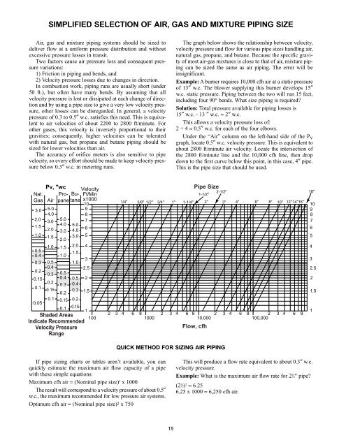
If pipe sizing charts or tables aren’t available, you can<br />
quickly estimate the maximum air flow capacity of a pipe<br />
with these simple equations:<br />
Maximum cfh air = (Nominal pipe size) 2 x 1000<br />
The result will correspond to a velocity pressure of about 0.5″<br />
w.c., the maximum recommended for low pressure air systems.<br />
Optimum cfh air = (Nominal pipe size) 2 x 750<br />
QUICK METHOD FOR SIZING AIR PIPING<br />
15<br />
The graph below shows the relationship between velocity,<br />
velocity pressure and flow for various pipe sizes handling air,<br />
natural gas, propane, and butane. Because the specific gravity<br />
of most air-gas mixtures is close to that of air, mixture piping<br />
can be sized the same as air piping. The error will be<br />
insignificant.<br />
Example: A burner requires 10,000 cfh air at a static pressure<br />
of 13″ w.c. The blower supplying this burner develops 15″<br />
w.c. static pressure. Piping between the two will run 15 feet,<br />
including four 90° bends. What size piping is required?<br />
Solution: Total pressure available for piping losses is<br />
15″ w.c. - 13 ″ w.c. = 2″ w.c.<br />
This allows a velocity pressure loss of:<br />
2 ÷ 4 = 0.5″ w.c. for each of the four elbows.<br />
Under the “Air” column on the left-hand side of the Pv<br />
graph, locate 0.5″ w.c. velocity pressure. This is equivalent to<br />
about 2800 ft/minute air velocity. Locate the intersection of<br />
the 2800 ft/minute line and the 10,000 cfh line, then drop<br />
down to the first curve below this point, in this case, 4″ pipe.<br />
This is the pipe size that should be used.<br />
12" 14" 16"<br />
2 3 4 6 8 10,000 2 3 4 6 8 100,000 2 3 4 6 8<br />
Flow, cfh<br />
4"<br />
This will produce a flow rate equivalent to about 0.3″ w.c.<br />
velocity pressure.<br />
Example: What is the maximum air flow rate for 21 ⁄ 2" pipe?<br />
(21 ⁄ 2) 2 = 6.25<br />
6.25 x 1000 = 6,250 cfh air.<br />
6"<br />
8"<br />
10"<br />
18"<br />
10<br />
9<br />
8<br />
7<br />
6<br />
5<br />
4<br />
3<br />
2.5<br />
2<br />
1.5<br />
1